KR20060107187A - Painless laser blood collection device and blood glucose measurement device using the same - Google Patents
Painless laser blood collection device and blood glucose measurement device using the sameDownload PDFInfo
- Publication number
- KR20060107187A KR20060107187AKR1020050029253AKR20050029253AKR20060107187AKR 20060107187 AKR20060107187 AKR 20060107187AKR 1020050029253 AKR1020050029253 AKR 1020050029253AKR 20050029253 AKR20050029253 AKR 20050029253AKR 20060107187 AKR20060107187 AKR 20060107187A
- Authority
- KR
- South Korea
- Prior art keywords
- laser
- blood
- glucose measurement
- blood glucose
- painless
- Prior art date
- Legal status (The legal status is an assumption and is not a legal conclusion. Google has not performed a legal analysis and makes no representation as to the accuracy of the status listed.)
- Granted
Links
Images


Classifications
- A—HUMAN NECESSITIES
- A61—MEDICAL OR VETERINARY SCIENCE; HYGIENE
- A61B—DIAGNOSIS; SURGERY; IDENTIFICATION
- A61B5/00—Measuring for diagnostic purposes; Identification of persons
- A61B5/15—Devices for taking samples of blood
- A61B5/151—Devices specially adapted for taking samples of capillary blood, e.g. by lancets, needles or blades
- A61B5/15134—Bladeless capillary blood sampling devices, i.e. devices for perforating the skin in order to obtain a blood sample but not using a blade, needle, canula, or lancet, e.g. by laser perforation, suction or pressurized fluids
- A61B5/15136—Bladeless capillary blood sampling devices, i.e. devices for perforating the skin in order to obtain a blood sample but not using a blade, needle, canula, or lancet, e.g. by laser perforation, suction or pressurized fluids by use of radiation, e.g. laser
- A—HUMAN NECESSITIES
- A61—MEDICAL OR VETERINARY SCIENCE; HYGIENE
- A61B—DIAGNOSIS; SURGERY; IDENTIFICATION
- A61B5/00—Measuring for diagnostic purposes; Identification of persons
- A61B5/145—Measuring characteristics of blood in vivo, e.g. gas concentration or pH-value ; Measuring characteristics of body fluids or tissues, e.g. interstitial fluid or cerebral tissue
- A—HUMAN NECESSITIES
- A61—MEDICAL OR VETERINARY SCIENCE; HYGIENE
- A61B—DIAGNOSIS; SURGERY; IDENTIFICATION
- A61B5/00—Measuring for diagnostic purposes; Identification of persons
- A61B5/15—Devices for taking samples of blood
- A61B5/150007—Details
- A61B5/150015—Source of blood
- A61B5/150022—Source of blood for capillary blood or interstitial fluid
- A—HUMAN NECESSITIES
- A61—MEDICAL OR VETERINARY SCIENCE; HYGIENE
- A61B—DIAGNOSIS; SURGERY; IDENTIFICATION
- A61B5/00—Measuring for diagnostic purposes; Identification of persons
- A61B5/15—Devices for taking samples of blood
- A61B5/150007—Details
- A61B5/150374—Details of piercing elements or protective means for preventing accidental injuries by such piercing elements
- A61B5/150534—Design of protective means for piercing elements for preventing accidental needle sticks, e.g. shields, caps, protectors, axially extensible sleeves, pivotable protective sleeves
- A—HUMAN NECESSITIES
- A61—MEDICAL OR VETERINARY SCIENCE; HYGIENE
- A61B—DIAGNOSIS; SURGERY; IDENTIFICATION
- A61B5/00—Measuring for diagnostic purposes; Identification of persons
- A61B5/15—Devices for taking samples of blood
- A61B5/157—Devices characterised by integrated means for measuring characteristics of blood
- G—PHYSICS
- G01—MEASURING; TESTING
- G01N—INVESTIGATING OR ANALYSING MATERIALS BY DETERMINING THEIR CHEMICAL OR PHYSICAL PROPERTIES
- G01N33/00—Investigating or analysing materials by specific methods not covered by groups G01N1/00 - G01N31/00
- G01N33/48—Biological material, e.g. blood, urine; Haemocytometers
- G01N33/50—Chemical analysis of biological material, e.g. blood, urine; Testing involving biospecific ligand binding methods; Immunological testing
- G01N33/66—Chemical analysis of biological material, e.g. blood, urine; Testing involving biospecific ligand binding methods; Immunological testing involving blood sugars, e.g. galactose
- G—PHYSICS
- G01—MEASURING; TESTING
- G01N—INVESTIGATING OR ANALYSING MATERIALS BY DETERMINING THEIR CHEMICAL OR PHYSICAL PROPERTIES
- G01N2800/00—Detection or diagnosis of diseases
- G01N2800/04—Endocrine or metabolic disorders
- G01N2800/042—Disorders of carbohydrate metabolism, e.g. diabetes, glucose metabolism
Landscapes
- Health & Medical Sciences (AREA)
- Life Sciences & Earth Sciences (AREA)
- Physics & Mathematics (AREA)
- Engineering & Computer Science (AREA)
- Molecular Biology (AREA)
- Hematology (AREA)
- Biomedical Technology (AREA)
- Pathology (AREA)
- General Health & Medical Sciences (AREA)
- Public Health (AREA)
- Medical Informatics (AREA)
- Surgery (AREA)
- Animal Behavior & Ethology (AREA)
- Heart & Thoracic Surgery (AREA)
- Biophysics (AREA)
- Veterinary Medicine (AREA)
- Optics & Photonics (AREA)
- Chemical & Material Sciences (AREA)
- Urology & Nephrology (AREA)
- Immunology (AREA)
- Microbiology (AREA)
- Cell Biology (AREA)
- Biotechnology (AREA)
- Food Science & Technology (AREA)
- Medicinal Chemistry (AREA)
- Analytical Chemistry (AREA)
- Biochemistry (AREA)
- General Physics & Mathematics (AREA)
- Diabetes (AREA)
- Dermatology (AREA)
- Measurement Of The Respiration, Hearing Ability, Form, And Blood Characteristics Of Living Organisms (AREA)
Abstract
Translated fromKoreanDescription
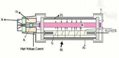
Translated fromKorean도 1은 본 발명의 일 실시예에 따른 무통 레이저 채혈장치를 나타낸 모형도.1 is a model showing a pain-free laser blood collection device according to an embodiment of the present invention.
도 2는 본 발명의 바람직한 실시예에 따른 어댑터를 나타낸 모형도.Figure 2 is a model diagram showing an adapter according to a preferred embodiment of the present invention.
도 3은 도 2의 어댑터에 접속되는 캡을 나타낸 모형도.3 is a schematic view showing a cap connected to the adapter of FIG.
도 4는 본 발명의 일 실시예에 따른 혈당측정장치를 나타낸 모형도.Figure 4 is a model showing a blood glucose measurement apparatus according to an embodiment of the present invention.
도 5는 도 4의 혈당측정장치를 더욱 상세히 나타낸 모형도.Figure 5 is a model showing the blood glucose measurement apparatus of Figure 4 in more detail.
******** 도면 부호의 설명 **************** Explanation of Reference Symbols ********
2...배터리 3...파워서플라이2
4...커패시터 5...플래시 램프4
6...Er:YAG크리스털 7...레이저 미러6 ... Er: YAG Crystal 7 ... Laser Mirror
8...포커싱렌즈 9...캡8
10...인터록 스위치 홀 11...쉴드홀더10 ...
12...커넥터 13...혈당측정회로12
14...LCD 15...모드 버튼14 ...
16...PCB16 ... PCB
본 발명은 레이저를 이용한 무통 채혈장치 및 동 채혈장치를 포함하는 혈당측정장치에 관한 것이다.The present invention relates to a blood glucose measurement apparatus including a painless blood collection device and the same blood collection device using a laser.
더욱 구체적으로, 본 발명은 의료분야에서 사용되는 Er:YAG 레이저 기술을 이용하여 무통 채혈과 혈당측정을 단일 장비에서 수행하는 혈당측정 분야의 신기술에 관한 것으로서, 물에 대한 흡수력이 강해 인체에 대한 위해가 거의 없는 파장 2,940㎚의 레이저가 방출되는 Er:YAG 레이저 헤드를 이용한 의료용 레이저 장치에 관한 것이다.More specifically, the present invention relates to a new technology in the field of blood glucose measurement using the Er: YAG laser technology used in the medical field for painless blood collection and blood glucose measurement in a single device. The present invention relates to a medical laser device using an Er: YAG laser head, which emits a laser having a wavelength of 2,940 nm with almost no light.
일반적으로 무통 채혈에 사용되는 Er:YAG 레이저 헤드는 금속체의 표면에 은이나 니켈, 구리 또는 이들의 합금 등을 여러 차례 증착하거나 도금한 후 그 표면을 가공하여 만든 리플렉터(reflector)로 상기 레이저 헤드의 외형을 형성하며, 상기 리플렉터의 내부에 고출력의 에너지를 발생하기 위한 레이저 펌핑용 플래시 램프(flash lamp)와 Er:YAG 크리스털을 각각 내장하고 있다.In general, Er: YAG laser head used for painless blood collection is a reflector made by depositing or plating silver, nickel, copper or their alloys on the surface of a metal body several times and then processing the surface. The laser pumping flash lamp and Er: YAG crystal for generating high power energy are embedded in the reflector.
상기 Er:YAG 레이저 헤드에서 방출되는 레이저의 강도는 플래시 램프의 발광량과 Er:YAG 크리스털의 체적 및 크기에 따라 달라지며, 리플렉터의 매끈한 표면에 의해 레이저의 직선성이 유지되고 반사가 방지된다.The intensity of the laser emitted from the Er: YAG laser head depends on the amount of light emitted from the flash lamp and the volume and size of the Er: YAG crystal. The smooth surface of the reflector maintains the linearity of the laser and prevents reflection.
그런데 종래 구성의 무통 레이저 채혈장치는 Er:YAG 레이저 헤드와 피부(채 혈부위) 사이의 접촉이 불량하여, 레이저에 의해 피부가 천공될 때 "퍽"하는 마찰음이 그대로 들릴 뿐 아니라 약간의 연기(살갗이 타는 연기)가 누출되며, 채혈된 피부 주위에 하얀 반점이 형성되어 환자의 심리를 불안하게 하는 단점이 있다. 또한, 플래시 램프의 섬광과 레이저가 육안으로 관찰되기 때문에, 피부에 특별히 나쁜 영향을 주지 않는다 하더라도 눈의 망막에 이롭지는 못할 것이라는 염려가 있다. 이러한 이유로, 종래의 Er:YAG 레이저 헤드를 이용한 채혈장치는 바늘형태의 란셋(lancet)과 달리 무통으로 채혈할 수 있는 좋은 점이 있음에도 채혈에 대한 다른 공포감을 조장하여 동 채혈장치의 사용의욕을 위축하는 결과를 가져왔다.However, the conventional painless laser blood collection device has poor contact between the Er: YAG laser head and the skin (blood collection area), so that when the skin is perforated by the laser, the sound of "pucking" is heard as it is, and a slight smoke ( Flesh smoke) leaks, white spots are formed around the blood collected to disturb the psychology of the patient. In addition, since the flash and the flash of the flash lamp are visually observed, there is a concern that even if it does not have a particularly bad effect on the skin, it will not be beneficial to the retina of the eye. For this reason, the conventional blood collection device using Er: YAG laser head has the advantage that blood can be collected painlessly, unlike needle-type lancets, which encourages other fears of blood collection and weakens the user's desire to use the blood collection device. Brought the result.
본 발명과 관련이 있는 산업분야로서 혈당측정에 스트립(strip)이 이용되는 기술 분야를 살펴보면 세계적으로 미국의 존슨&존슨, 애보트, 독일의 로슈 등 3대 업체가 시장을 장악하고 있고, 국내의 경우에는 올메디쿠스, 인포피아, 아이센스 등이 주사침 형태의 란셋(lancet)으로 채혈한 후 혈당을 측정하는 타입의 장비를 시판하고 있다.Looking at the technical field that strips are used to measure blood glucose as an industrial field related to the present invention, three major companies such as Johnson & Johnson, Abbott and Roche of Germany dominate the market worldwide. Olmediks, Infopia, and Eye Sense have marketed a type of device that measures blood glucose after collecting blood with a lancet in the form of a needle.
하루 2∼3회 이상 실시간으로 혈당측정을 해야 하는 인슐린 의존형 환자의 경우 주로 손가락의 끝 부분을 란셋으로 찔러 채혈하는데, 채혈 시 피부조직을 절개하는 형태로 혈액을 채취하기 때문에 고통이 심할 뿐 아니라 필요 이상으로 많은 혈액이 채혈되므로 반드시 지혈해 주어야 하고, 지혈 후에도 채혈 부위의 상처가 오랫동안 남아 AIDS나 각종 세균들로 오염될 우려가 있다.In the case of insulin-dependent patients who need to measure blood glucose in real time more than 2-3 times a day, blood is pierced with a lancet at the end of the finger, which is not only painful but also necessary because blood is collected by cutting the skin tissue. This is because a lot of blood is collected, so must be bleeding, and after the hemostasis of the blood collection site for a long time may be contaminated with AIDS or various bacteria.
이로 인하여, 당뇨환자가 혈당측정을 기피하게 되어 당뇨병의 지속적이고 체 계적인 관리가 소홀하게 되고, 그 결과로 당뇨병의 완치율이 낮고 재발률이 높아지는 원인이 되고 있다.As a result, diabetic patients avoid blood glucose measurement, and the continuous and systematic management of diabetes is neglected, and as a result, the cure rate of diabetes is low and the recurrence rate is high.
최근에는 혈당을 간접적으로 측정하는 적외선 주사 방식의 혈당측정기가 선보이기도 했지만, 직접적으로 채혈하는 방식에 비해 혈당 측정값에 대한 신뢰도가 떨어져 잘 사용되지 않는 상황이다.Recently, a blood glucose meter of infrared scanning method that measures blood glucose indirectly was introduced, but the reliability of blood glucose measurement value is less used than the method of collecting blood directly.
한편, 종래에는 상술한 채혈장치와 혈당측정장치가 각각 별개로 제작·공급됨으로써, 혈당측정을 하려면 이들 2종류의 장비가 늘 구비되어야 하므로 장비의 구입과 보관/운반 및 이용에 불편이 수반되었다.On the other hand, conventionally, since the above-described blood collection device and blood glucose measurement device are manufactured and supplied separately, these two types of equipment should always be provided in order to measure blood glucose, so that inconveniences in purchasing, storing, transporting, and using the equipment were involved.
본 발명은 이러한 종래 문제점을 개선하기 위해 안출된 것으로서, Er:YAG 레이저 헤드 부분과 피부 사이의 밀착성이 우수한 무통 레이저 채혈장치를 제공함에 목적이 있다.The present invention has been made to improve such a conventional problem, and an object of the present invention is to provide a painless laser blood collection device excellent in adhesion between the Er: YAG laser head portion and the skin.
또한, 본 발명은 국내에 20만 명 내지 30만 명 정도가 있는 것으로 추정되는 매일 2∼3회 정도의 혈당측정이 필요한 인슐린 의존형 당뇨환자가 통증 없이 적은 양의 혈액을 채취한 후 이를 이용하여 안전하게 혈당을 측정할 수 있도록, 무통 채혈과 혈당측정이 단일 장비에서 이루어지는 개인 휴대용의 혈당측정장치를 제공함에 목적이 있다.In addition, the present invention is a insulin-dependent diabetic patients needing 2-3 times daily blood glucose measurement estimated that there are about 200,000 to 300,000 people in Korea safely after using a small amount of blood collected without using it It is an object of the present invention to provide a personal hand-held blood glucose measurement device in which painless blood collection and blood glucose measurement are performed in a single device so that blood glucose can be measured.
상기의 기술적 과제를 해결하기 위한 본 발명의 무통 레이저 채혈장치는 피부와의 밀착성을 향상하기 위한 소정의 어댑터(adaptor)가 Er:YAG 레이저 헤드의 선단 부분에 취부된 것을 특징으로 한다. 보다 구체적으로는 청구항 1에 기재된 바와 같이, 레이저가 생성되어 일방향으로 조사되는 Er:YAG 레이저 헤드와, 상기 Er:YAG 레이저 헤드의 선단으로부터 소정 거리만큼 떨어져 위치되는 어댑터 및 상기 레이저가 직진할 수 있게 배치한 Er:YAG 레이저 헤드와 어댑터의 외면에 에워싸인 케이스를 포함하는 것을 특징으로 한다.The painless laser blood collection device of the present invention for solving the above technical problem is characterized in that a predetermined adapter (adaptor) for improving the adhesion to the skin is attached to the tip of the Er: YAG laser head. More specifically, as described in claim 1, a laser is generated so that the Er: YAG laser head irradiated in one direction, the adapter positioned a predetermined distance away from the tip of the Er: YAG laser head, and the laser can go straight. And a case surrounded by an outer surface of the disposed Er: YAG laser head and the adapter.
Er:YAG 레이저 헤드는 A) 내부에 수용공간이 형성된 리플렉터(reflector)와; B) 리플렉터의 수용공간에 삽입되되 양단이 수용공간의 외부로 노출되게 삽입되는 Er:YAG 크리스털과; C) Er:YAG 크리스털의 적어도 어느 일 측 단에 고정되는 레이저 미러와; D) Er:YAG 크리스털로부터 소정 거리만큼 떨어져 상기 수용공간에 내삽되는 플래시 램프를 포함할 수 있다.(도 1 참조)Er: YAG laser head A) and a reflector (reflector) formed with a receiving space inside; B) Er: YAG crystal which is inserted into the receiving space of the reflector, both ends of which are inserted so as to be exposed to the outside of the receiving space; C) a laser mirror fixed to at least one end of the Er: YAG crystal; D) Er: YAG crystal may include a flash lamp interpolated into the receiving space by a predetermined distance (see Fig. 1).
상기어댑터(adaptor)는 레이저 조사 시에 발생하는 소음, 섬광, 피부 표면에서의 연기 등을 차단할 수 있도록 폴리에스테르(polyester) 등의 재료를 고강도로 열 압착한 소재로 제작하고, 구조적으로는 채혈부위의 피부가 어댑터 안으로 약간 묻혀들어가는 구조가 되도록 제작하는 것이 바람직하다. 또한, 상기 어댑터 내에 포커싱렌즈(focusing lens)를 설치하여, 피부에 조사되는 레이저의 면적을 최소화하는 것이 바람직하다. 더욱 바람직하게는, 피부와 접촉되는 어댑터의 선단에 소정 구조의 캡을 개재하여, 채혈된 혈액이 동 어댑터와 포커싱렌즈에 묻지 않 고 채혈부위의 상처가 최소로 되게 하여, 장치가 오동작하는 것을 방지하고 피 채혈자의 심리적-실제적 통증을 감소시키는 것이 좋다. 또한 위생적인 측면에서 상기 캡은 상기 어댑터의 선단에 용이하게 탈착될 수 있도록 하여 1회용으로 사용하는 것이 바람직하다. 하기 실시예에 의한 장치의 설명에서 볼 수 있듯이, 상기 어댑터의 내부는 사용과정에서 감압이 형성되므로, 천공된 피부로부터 혈액이 용이하게 흘러나오도록 하는 역할도 하게 된다. 이는 종래기술과는 달리, 보다 적은 크기의 피부 천공으로도 필요한 만큼의 혈액을 신속하게 채취할 수 있음을 의미한다.Theadapter is made of a material, such as polyester (polyester) with a high-strength heat compression to block the noise, glare, smoke on the skin surface, etc. generated during laser irradiation, structurally collected blood It is desirable to make the structure so that the skin is slightly buried into the adapter. In addition, it is desirable to provide a focusing lens in the adapter to minimize the area of the laser irradiated to the skin. More preferably, through the cap having a predetermined structure at the tip of the adapter in contact with the skin, the blood collected is not contacted with the copper adapter and the focusing lens to minimize the wound on the blood collection site, thereby preventing the device from malfunctioning. And reduce the psycho-real pain of the blood sampler. In addition, in terms of hygiene, the cap is preferably used for one-time use so that the cap can be easily detached to the tip of the adapter. As can be seen in the description of the device according to the following examples, since the inside of the adapter is depressurized during use, it also serves to facilitate blood flow from the perforated skin. This means that, unlike the prior art, it is possible to quickly collect as much blood as needed even with a smaller size of skin perforation.
본 발명의 청구항 3은 상기 조건에 부합하는 구체적 사례로서, A) Er:YAG 레이저 헤드의 선단에 근접하여 위치되는 포커싱렌즈홀더와; B) 포커싱렌즈홀더의 내부 관통로에 삽입되는 포커싱렌즈와; C) 포커싱렌즈홀더의 선단에 접속되는 피부밀착수단을 포함하여 된 어댑터가 청구되고 있다. 또한, 본 발명의 청구항 4에는 피부와 접촉되는 부분이 곡면으로 가공되고, 사용시 발생되는 소음을 효율적으로 흡음할 수 있도록 레이저가 통과하는 내부통로의 일부가 주름진 것을 특징으로 하는 피부밀착수단이 청구되고 있다.(도 2 참조)According to a third aspect of the present invention, there is provided a specific example that satisfies the above condition, comprising: A) a focusing lens holder positioned close to the tip of an Er: YAG laser head; B) a focusing lens inserted into the through passage of the focusing lens holder; C) An adapter is claimed that includes skin contact means connected to the tip of a focusing lens holder. In addition,
또한, 청구항 5에는 곡면으로 가공된 피부밀착수단의 선단에 홈부가 형성되고 이 홈부에 소정 형상의 캡이 추가로 삽입된 무통 레이저 채혈장치가 개시되어 있고, 청구항 6에는 상기 캡과 홈부의 보다 바람직한 구조와 조립에 관한 것이 언급되어 있다. 예컨대, 상기 캡은 피부와의 밀착부위가 곡면으로 가공되되 그 중앙부에 레이저 홀이 형성되고, (하기에서 설명되듯이) 사용과정에서 감압이 작용되도록 진공 홀이 형성되어 있으며, 상기 포커싱렌즈 측으로는 채혈 시 혈액이 튀어 상기 어댑터의 내부 또는 포커싱렌즈를 오염시키는 것을 방지하기 위하여 통형상의 돌출부가 형성되고, 외주면에는 사용시 공기가 통과되지 않으면서 흔들림을 방지하기 위한 소정의 구조물이 형성될 수 있다.(도 3 참조) 또한, 상기 캡이 끼워져 고정되는 홈부는 상기 진공 홀과의 대응 부위에 진공홀더가 형성되어 그 속에 진공스위치와 진공조절버튼이 각각 추가로 설치되고, 상기 조절 포인터와의 대응 부위에 인터록 스위치 홀(10)이 형성되어 그 내부에 인터록 스위치 센서와 스프링이 추가로 설치될 수 있다. 따라서 본 발명에 의한 장치를 사용하는 과정에서 <피부-캡의 측면-캡의 외면-어댑터의 내면> 사이의 접촉부분이 밀폐되고 감압장치(예를들면 진공스위치)가 작동되어 어댑터의 내부가 감압상태로 유지되게 된다.Further, claim 5 discloses a painless laser blood collection device in which a groove is formed at the tip of the curved skin processing means, and a cap having a predetermined shape is further inserted into the groove, and in
본 발명의 혈당측정장치는 상술한 무통 레이저 채혈장치의 구성에 추가로 스트립 삽입용의 커넥터와 혈당측정회로 및 LCD 등의 표시수단이 구비됨으로써, 혈액 채취와 혈당측정이 단일 장비에서 수행되도록 한 것을 특징으로 한다.(도 4 및 도 5 참조) 바람직하게는, 각종 구성요소의 작동을 제어하기 위한 마이크로프로세서가 PCB에 탑재되고, 과거의 혈당측정결과를 기록/관리하는 프로그램이 내장되는 것이다.The blood glucose measurement apparatus of the present invention is provided with a connector for inserting a strip, a blood glucose measurement circuit, and an LCD, in addition to the configuration of the above-described painless laser blood collection apparatus, so that blood collection and blood glucose measurement can be performed in a single device. (See FIGS. 4 and 5) Preferably, a microprocessor for controlling the operation of various components is mounted on the PCB, and a program for recording / managing the blood glucose measurement results of the past is embedded.
본 발명에 의한 장치에 있어서, 장치의 운전과 조작, 상태 또는 결과의 디스플레이를 위한 입출력장치수단이 필요하고, 이를 구성하는 것은 당업자에게 있어 매우 용이한 일이다. 즉, 본 발명의 기술적 사상의 범주 내에서 예를들면 레이저의 출력에너지를 조절하는 방법이나 그 조절장치, 레이저의 초점을 조절하는 방법 이나 그 조절장치, 상태 또는 결과를 디스플레이하는 수단 등을 구성하는 것은 당업계 뿐 아니라 전자산업 분야에서 널리 알려져 있다. 따라서 본 명세서에서는 구체적인 입출력 수단에 대한 언급과 설명을 생략하였다.In the apparatus according to the present invention, input and output device means for operation and operation of the apparatus, and display of status or results are required, and it is very easy for a person skilled in the art to configure them. That is, within the scope of the technical idea of the present invention, for example, a method of adjusting the output energy of the laser, a control device thereof, a method of adjusting the focus of the laser, a control device thereof, a means of displaying a state or a result, etc. It is widely known in the electronics industry as well as in the art. Therefore, in this specification, reference to and description of specific input and output means have been omitted.
이하 첨부도면을 참조하여 본 발명의 실시예에 따른 무통 레이저 채혈장치와 혈당측정장치의 구성 및 작용을 설명한다.Hereinafter, with reference to the accompanying drawings will be described the configuration and operation of the painless laser blood collection device and blood glucose measurement device according to an embodiment of the present invention.
무통 레이저 채혈장치Painless Laser Blood Collection Device
도 1 내지 도 3은 본 발명의 바람직한 실시예에 따른 무통 레이저 채혈장치와 동 채혈장치의 주요 구성요소 중 하나인 어댑터 및 동 어댑터에 접속되는 캡을 나타낸 모형도이다.1 to 3 is a schematic diagram showing a painless laser collection device according to a preferred embodiment of the present invention and an adapter which is one of the main components of the collection device and a cap connected to the same adapter.
도면에서, 본 실시예의 주요 구성요소인 Er:YAG 레이저 헤드(18)는 내부에 수용공간이 형성된 리플렉터(reflector)(23)와, 상기 리플렉터(23)의 수용공간에 삽입되되 양단이 수용공간의 외부로 노출되게 삽입된 Er:YAG 크리스털(6)과, 이 Er:YAG 크리스털(6)의 적어도 어느 일 측 단에 고정된 레이저 미러(7) 및 상기 Er:YAG 크리스털(6)로부터 소정 거리만큼 떨어져 상기 수용공간에 내삽된 플래시 램프(Flash Lamp)(5)로 이루어져 있다.In the drawing, the main component Er:
상기Er:YAG 크리스털(crystal)(6)은 플래시 램프(5)에서 발광하는 섬광을 유도·집속하여 크리스털의 Lasing transition 4I11/2→4I13/2에 의해 0.5∼0.55 mJ의 파장(wavelength) 2,940㎚의 친수성이 강한 레이저로 발생시켜 주는 구성요소로서, 크리스털의 결정구조와 밀도 및 체적에 따라 레이저의 세기가 결정된다.TheEr:
본 실시예에서는 레이저가 일정한 방향으로 고르게 조사됨과 동시에 그 강도가 높게 유지되도록 미세한 Yttrium Aluminum Garnet(Y3Al5O12+3) 분말을 Melting Point 1870℃에서 Dopant시켜 성형하고 OH-free Special Coating으로 표면처리를 한 다음 표면의 거칠기를 1㎛ 이하로 정밀하게 가공하였다. 여기서, 상기 Er:YAG 크리스털(6)은 결정구조에 불순물이 전혀 없는 맑고 투명한 상태로 결정체가 유지되어야 하기 때문에 Dopant에 상당히 오랜 시간이 소요되며, 1㎛ 이하로 정밀하게 절단가공 및 연마가공되어야 레이저(빔)의 직선성이 유지되고 간섭 산란이 없어지므로 숙련된 기술인력에 의한 Know-how가 필요하다.In this embodiment, the fine Yttrium Aluminum Garnet (Y3Al5O12 + 3) powder is doped at Melting Point 1870 ℃ and surface-treated with OH-free Special Coating so that the laser is evenly irradiated in a certain direction and its intensity is kept high. The roughness of the surface was precisely processed to 1 μm or less. Here, the Er: YAG crystal (6) takes a very long time to the dopant because the crystal must be maintained in a clear and transparent state without any impurities in the crystal structure, and must be precisely cut and polished to less than 1㎛ laser Since the linearity of the beam is maintained and interference scattering is eliminated, a know-how by skilled technical personnel is required.
레이저 펌핑용의플래시 램프(5)는 상기 Er:YAG 크리스털(6)에 에너지를 공급하기 위해 약 100W 정도의 섬광을 발생시키는 장치로서, 본 실시예의 경우에는 진공상태의 원통형 막대 유리관 속에 400∼700mmHg의 제논가스(zenon gas)를 충전한 다음 약 40∼45㎜ 정도 간격을 두고 설치된 양 전극에 고전압의 트리거전류를 인가하여 80∼100WS 수준의 섬광이 방전되도록 유도하였다.The
Er:YAG 크리스털(6)과 플래시 램프(5)가 적당한 간격을 두고 설치되는리플렉터(23)는 Er:YAG 레이저 헤드의 외관을 형성하는 구성요소로, 플래시 램프(5)에서 발광된 섬광을 리플렉터의 내 벽면에서 180° 반사시켜 Er:YAG 크리스털(6)로 유도 집속하는 역할을 한다. 본 실시예에서는 상기 리플렉터의 제작 시, 쿼츠 글라스(quartz glass)의 표면에 1차적으로 은을 증착하여 반사율 98% 이상을 유지시 키고, 상기 은(Ag)의 산화를 방지하기 위해 니켈과 구리합금으로 코팅한 후 표면을 밀링(milling)하였다.The
부호 7로 표시된 레이저 미러(7)는 상기 Er:YAG 크리스털(6)에 의해 집속된 레이저가 일정한 방향으로 직선성을 유지하면서 조사되도록 하는 구성요소로, 레이저의 조사각도와 방향에 따라 10-9m의 편평도가 유지될 수 있게 정밀하게 연마 가공하였고, 그 표면을 폴리싱(polishing)하여 매끄럽게 하였다. 또한, 레이저가 조사되는 방향(선단)에 장착된 레이저 미러(7)는 투과율이 95% 이상으로 유지될 수 있게 가공하였고, 반대쪽(후단)에 장착된 레이저 미러(7)는 상기 Er:YAG 크리스털(6)에 집속된 레이저의 90% 이상이 180° 반대 방향으로 반사될 수 있게 가공하여 직선성을 유지시키면서 동시에 조사방향의 유도를 꾀하였다. 이는 종래 Er:YAG 레이저 기술을 한 단계 발전시킨 것으로서, Er:YAG 크리스털(6)의 양단에 상기 레이저 미러(7)를 직접으로 접속한 후 코팅 처리하여 간섭과 산란에 의한 레이저의 손실을 최소화하고 투과도와 레이저의 직선성을 향상시킨 결과를 낳았다.The
본 실시예의 어댑터(19)는 도 1 및 도 2에서 참조 되듯이 상술한 Er:YAG 레이저 헤드(18) 레이저 미러(7)의 반대쪽 선단에 장착되며, 포커싱렌즈홀더(43)와, 상기 포커싱렌즈홀더(43)의 내부 관통로에 삽입되는 포커싱렌즈(focusing Lens)(8)와, 상기 포커싱렌즈홀더(43)의 선단에 접속되는 피부밀착수단(좌측면이 곡면으로 된 대경부)으로 구성되어 있다.The
상기 포커싱렌즈(8)는 일정한 방향으로 조사되는 레이저(Laser)를 정확한 초 점으로 압축하여 채혈대상 피부 표면에 집속시켜 주는 구성요소로서, 피부 표면에 지름 0.1∼2㎜ 구멍을 0.2∼4㎜의 깊이로 천공할 수 있지만 진피조직에 있는 신경세포를 자극하여 통증을 유발하는 일이 없도록 피부 침투깊이를 0.5㎜ 이하로 하고 지름도 0.4∼0.6㎜범위가 되도록 제작하였다. 이러한 피부 침투 깊이와 천공지름을 유지하기 위해서 레이저가 조사되는 방향의 레이저 미러(7)로부터 포커싱렌즈(8)까지의 거리를 13㎜∼15㎜로 유지하였으며, 사용시 포커싱렌즈(8)에서부터 천공되는 피부표면 까지의 거리가 14㎜∼16㎜ 정도 되도록 조정하였다.The focusing
이와 같이 하면, 피부의 표피조직과 진피조직 사이에 존재하는 모세혈관의 혈액 유동을 50μsec∼500μsec까지 자극하여 혈당측정에 필요한 0.5㎕ 이상의 혈액을 용이하게 채혈할 수 있고 상처 부위의 크기와 통증을 최소화할 수 있다. 따라서, 종래 채혈 시 살갗이 타는 냄새와 "퍽"하는 둔탁한 소리의 발생을 1차로 방지하는 효과가 있다. 한편, 본 실시예에서는 상기 포커싱렌즈(8)에 대해서도 간섭과 산란 및 효율을 높이기 위해 정밀하게 가공한 다음 10-9m까지 표면을 Polishing 하였다.In this way, the blood flow of capillaries existing between the epidermal and dermal tissues of the skin is stimulated to 50 μsec to 500 μsec to easily collect 0.5 μl or more of blood required for blood glucose measurement and minimize the size and pain of the wound site. can do. Therefore, there is an effect to prevent the first generation of a burning smell and "puck" dull sound in the conventional blood collection. In the present embodiment, the focusing
상술한 본 실시예의 어댑터(19)는 종래 기술의 근본적인 문제점이었던 플래시 램프(5)에서 발생하는 섬광과 채혈 시 발생하는 소음을 차단하고 흡수하는 역할을 하며, 채혈 부위를 진공상태로 만들어 혈액의 채취가 용이하게 이루어지게 하는 구조로 형성되어 있다. 즉, 본 발명에 의한 어댑터는 일종의 “밀폐식 방폭형” 어댑터(19)라 볼 수 있다.
상기 어댑터(19)는 포커싱렌즈(8)가 내장된 포커싱렌즈홀더(43)와 일체로 되어 있으며, 기밀성 유지를 통한 소음차단 효과를 높이기 위하여 압축 Polyester 재질에 의해 내부가 주름살 형태로 제작되었다.The
아울러, 최종적인 소음과 플래시 램프(5)에서 나오는 섬광을 차단하기 위해 발포 압축형 엔지니어링 플라스틱 재질의 케이스(25)로 그 주변을 밀봉하였다.In addition, in order to block the final noise and the flash from the flash lamp (5) it was sealed around the
또한, 도면부호 9로 표시된 캡(도 3 참조)은 손가락으로 눌러 주면 상기 어댑터(19)에 쉽게 삽입되도록 구성하였다. 또한, 채혈의 용이성과 채혈 시 유발되는 통증을 없애기 위해 캡(9)과 압축된 형태로 접촉하면서 기밀성을 유지하고, 진공상태에서 채혈대상 피부를 늘리고 압착·확장하여 혈액 채취가 용이하도록 소형 실린더 형태의 진공홀더(48)를 설치하였다. (그러나 본 실시예에서는 감압장치의 한 예로 진공홀더를 설치한 것고, 감압할 수 있는 어떠한 종류의 자동-수동 장치가 이에 적용될 수 있다.) 여기서, 부호 47은 상기 진공홀더(수동 진공발생기)와 캡을 손가락으로 눌렀을 때 기밀성이 유지될 수 있도록 접촉부위를 압착시키는 누름판 형태의 진공조절버튼이며, 부호 49는 수동으로 진공을 발생시키는 회전형 진공스위치를 나타낸 것이다.In addition, the cap (see FIG. 3) indicated by
또한, 상기 어댑터에 삽입되는 캡은 채혈대상 피부와의 밀착성이 우수하도록 신축성이 있고 부드러운 재질(예를들면 Silicon Rubber)인 것이 바람직하다.In addition, the cap is inserted into the adapter is preferably made of a flexible and soft material (for example, Silicon Rubber) so as to have good adhesion to the blood to be collected.
따라서, 본 실시예의 어댑터에 삽입되는 캡에 따르면 Er:YAG 레이저로 피부 표면을 천공할 때 포커싱렌즈에 혈액이 묻어 레이저의 직선성과 투과율이 저하되는 것을 방지할 수 있으며, 채혈된 혈액이 오염되는 것을 예방할 수 있다. 아울 러, 어댑터와 함께 연결되어 채혈대상 피부와 진공상태로 접촉되므로 모세혈관에서 혈액을 쉽게 채취할 수 있으며, 진공의 효과로 통증이 경감될 수 있다. 또한, 피부와 기밀하게 접촉되므로 어댑터의 특수한 압축형 폴리에스테르 구조로 레이저 조사 시 나타나는 소음이 방음형태로 차단된다. 또한 레이저 조사시(즉, 1회라도 사용시)에 상기 폴리에틸렌 필림이 레이저에 의해 구멍나게 되므로 사용전인지 사용후인지를 보다 간편하게 확인할 수 있는 장점이 있다.Therefore, according to the cap inserted into the adapter of the present embodiment, when the surface of the skin is punctured by the Er: YAG laser, blood can be prevented from falling on the focusing lens to reduce the linearity and transmittance of the laser. It can be prevented. In addition, since it is connected with the adapter to be in contact with the blood to be collected in a vacuum state, blood can be easily collected from capillaries, and the effect of vacuum can reduce pain. In addition, since the airtight contact with the skin, the adapter's special compression polyester structure prevents noise generated during laser irradiation in the form of sound insulation. In addition, since the polyethylene film is punctured by a laser at the time of laser irradiation (that is, even at the time of use), there is an advantage that it is easier to check whether it is before use or after use.
또한, 본 실시예에서는 상기 캡이 어댑터의 홈부(도 2에 은선으로 표시된 곡면 부위)에 손쉽게 삽입·고정됨으로써 유동에 의한 흔들림이 없도록 부호 52의 조절 포인터를 외면에 돌출시켰다. 상기 어댑터(19)의 내부로 삽입되어 포커싱렌즈와 대면하게 되는 통형상의 말단 부분에는 얇은 Polyethylene 필름(54)을 부착하여 레이저 조사 시의 간섭과 산란을 방지하였으며, 상기 어댑터의 진공홀더에 밀착되어 채혈 시 진공을 유지할 수 있도록 캡의 상단에 진공 홀(53)을 형성하였다.In addition, in this embodiment, the
또한, 상기 어댑터의 홈부에 캡이 완벽하게 고정되지 않으면 잠금 상태가 계속 유지되도록 인터록 스위치 버튼과 스프링(44) 및 인터록 센서(45)가 어댑터의 대경부 내측에 삽설되어 있다. 상기 캡이 완벽하게 고정될 경우, 인터록 스위치 케이블(46)을 통하여 Control PCB(16)에서 Interlock이 해제된다.In addition, the interlock switch button, the
혈당측정장치Blood glucose meter
첨부된 도 4는 본 발명의 일 실시예에 따른 혈당측정장치를 나타낸 모형도이 고, 도 5는 도 4에 도시된 혈당측정장치의 구성원리를 보다 상세히 나타낸 것이다.4 is a model diagram illustrating a blood glucose measurement apparatus according to an embodiment of the present invention, and FIG. 5 illustrates the membership of the blood glucose measurement apparatus illustrated in FIG. 4 in more detail.
도면에서 보듯이, 본 실시예에서는 장소에 무관하게 상시 사용이 가능하면서 휴대가 용이하도록, Er:YAG 크리스털(6)의 양단에 레이저 미러(7)를 장착하고, 고출력 커패시터(4)와 초소형 트랜스포머(21,22) 등으로 이루어진 파워서플라이(3)를 사용하여 장치의 소형화 및 경량화를 도모하였다. 또한, 리튬-이온 배터리(2)를 채용함으로써 AC전원의 공급 없이도 50회 이상 채혈과 혈당측정이 가능하도록 하였으며, 마이크로프로세서가 실장된 소형 PCB(16)를 채용하였다.As shown in the figure, in this embodiment, the
부호 11의 쉴드홀더(shield holder)에는 채혈부위 이외의 다른 곳에 레이저가 조사되지 않도록 레이저 빔 스토퍼 형태의 잠금장치를 설치하여 PCB(16) 및 LCD ready 표시와 연동시켜 혈당측정에만 사용될 수 있도록 하였다.The shield holder of the
부호 12의 커넥터는 혈당정보가 내장된 스트립(24)을 삽입하기 위한 구성요소로서, 동 스트립의 혈당정보는 혈당측정회로(13)에 전달되어 LCD를 통해 수치적으로 표시되고 측정된 혈당치가 저장된다.The
본 실시예에서는 Er:YAG 레이저 방식으로 채혈된 0.5㎕ 가량의 혈액을 수집하고 전기적인 화학반응에 따라 혈당정보를 제공하는 스트립(24)으로서, 채혈된 혈액을 흡수하는 블러드 인서트(blood insert)와 상기 흡수된 혈액으로 혈당정보의 수집이 가능한 지를 판단하는 인서트 센서 및 수집된 혈당정보를 스트립에 분주한 시약과 반응시켜 전기적인 화학분석 방식에 의해 혈당측정회로에 전송하는 접촉식 스트립 커넥터로 구성되어 있다.(미도시) 따라서, 소량의 혈액으로 혈당을 정확히 측정할 수 있다.In the present embodiment, the
상기 PCB(16)는 커패시터를 통해 전기공급량을 제어하고, 플래시 램프의 발광량을 60∼100WS로 조절하여 Er:YAG 레이저의 세기를 최소 0.1 J에서부터 최대 1 J 까지 조절하며, 레이저 조사 스위치와 모드조작 및 변환 버튼(15)을 제어하고, LCD에 표시되는 out-put 정보를 제어한다. 또한, 레이저 조사에 대한 인터록과 레이저 빔의 스토핑을 제어하고, 장치 회로의 안전보호를 제어한다. 이러한 제어와 통제를 위해, 본 실시예에서는 상기 PCB(16)에 16bit 마이크로프로세서를 사용하여 제어용 소프트웨어를 내장함으로써, 구성회로를 단순화 및 소형화하여 복잡한 회로구성으로 인해 차후 발생될 수 있는 각종 고장과 오동작의 발생 및 측정오차의 발생요인을 사전에 예방하였다.The
변형예Variant
한편, 본 발명의 혈당측정장치는 상술한 구성요소에 추가하여, 채혈하는 사람의 특성에 따라 플래시 램프에 공급되는 전기량을 애노드(Anode)와 캐소드(Cathode)에 인가되는 최소 250V전압에서 최대 360V 전압으로 조절함으로써 레이저의 세기를 변화시키는 버튼을 둘 수도 있다.On the other hand, the blood glucose measurement apparatus of the present invention, in addition to the above-described components, the amount of electricity supplied to the flash lamp according to the characteristics of the person collecting blood at a maximum voltage of 360V at a minimum 250V voltage applied to the anode and the cathode There is also a button to change the intensity of the laser by adjusting.
또한, 과거의 혈당측정치나 커패시터의 충전소요시간 등이 LCD 화면에 수치나 그래프로 표시하는 소정의 프로그램을 내장할 수 있다.In addition, a predetermined program may be incorporated in which past blood glucose readings, charging time of capacitors, etc. are displayed on the LCD screen in numerical values or graphs.
이상과 같이, 본 발명은 약 0.5 ㎕ 가량의 혈액을 무통으로 채혈한 후 이를 혈당측정에 사용하므로, 인슐린 의존형 당뇨환자에게 보급할 경우 큰 효과를 볼 수 있다. 또한, 조사되는 레이저가 피부 표면을 약 1000℃로 순간가열하여 멸균하므로, 채혈부위를 별도로 소독하지 않아도 에이즈나 세균으로 인한 오염을 예방할 수 있다. 또한, 피부와의 밀착성이 우수한 어댑터와 일회용 캡을 Er:YAG 레이저 헤드의 선단에 둠으로써, 살갗이 타는 연기와 둔탁한 소음의 발생을 1차적으로 저지하는 효과가 있다. 또한, 엔지니어링 플라스틱으로 된 케이스(25)에 의해 섬광이 외부로 노출되는 것을 차단할 수 있다.As described above, the present invention, since about 0.5 μl of blood without blood collection and then used for blood glucose measurement, it can be a great effect when spread to insulin-dependent diabetes patients. In addition, since the irradiated laser sterilizes the surface of the skin by instant heating at about 1000 ° C., it is possible to prevent contamination due to AIDS or bacteria without separately disinfecting the blood collection area. In addition, by placing an adapter and disposable cap excellent in adhesion to the skin at the tip of the Er: YAG laser head, there is an effect of primarily preventing the generation of burning smoke and dull noise. In addition, the glare can be prevented from being exposed to the outside by the
Claims (8)
Translated fromKoreanPriority Applications (1)
| Application Number | Priority Date | Filing Date | Title |
|---|---|---|---|
| KR1020050029253AKR100781323B1 (en) | 2005-04-08 | 2005-04-08 | Painless laser blood collection device and blood glucose measurement device using the same |
Applications Claiming Priority (1)
| Application Number | Priority Date | Filing Date | Title |
|---|---|---|---|
| KR1020050029253AKR100781323B1 (en) | 2005-04-08 | 2005-04-08 | Painless laser blood collection device and blood glucose measurement device using the same |
Publications (2)
| Publication Number | Publication Date |
|---|---|
| KR20060107187Atrue KR20060107187A (en) | 2006-10-13 |
| KR100781323B1 KR100781323B1 (en) | 2007-11-30 |
Family
ID=37627548
Family Applications (1)
| Application Number | Title | Priority Date | Filing Date |
|---|---|---|---|
| KR1020050029253AExpired - LifetimeKR100781323B1 (en) | 2005-04-08 | 2005-04-08 | Painless laser blood collection device and blood glucose measurement device using the same |
Country Status (1)
| Country | Link |
|---|---|
| KR (1) | KR100781323B1 (en) |
Cited By (4)
| Publication number | Priority date | Publication date | Assignee | Title |
|---|---|---|---|---|
| KR100782142B1 (en)* | 2006-04-14 | 2007-12-04 | (주)아이소텍 | Er: very low bloodless blood collection device using BA laser and blood glucose measurement device using it |
| KR102430385B1 (en)* | 2021-10-21 | 2022-08-08 | 김지나 | Blood collector |
| KR20230028079A (en)* | 2021-08-20 | 2023-02-28 | 이석제 | Smart insulin injection device with blood glucose measurement |
| WO2023027250A1 (en)* | 2021-08-23 | 2023-03-02 | 이석제 | Smart insulin-injecting device capable of measuring blood sugar |
Families Citing this family (7)
| Publication number | Priority date | Publication date | Assignee | Title |
|---|---|---|---|---|
| KR100989807B1 (en)* | 2008-08-27 | 2010-10-29 | (주)아이소텍 | One touch laser blood glucose measurement device and blood glucose measurement method using the same |
| WO2011145751A1 (en)* | 2010-05-17 | 2011-11-24 | (주)아이소텍 | Laser blood glucose meter |
| KR101001182B1 (en) | 2010-06-01 | 2010-12-15 | (주)아이소텍 | strip used for blood glucose measurement device |
| KR102085069B1 (en)* | 2018-02-23 | 2020-03-05 | (주)셀레메디 | Skin penetration apparatus using laser |
| WO2025155056A1 (en)* | 2024-01-16 | 2025-07-24 | 주식회사 엠비트로 | Laser output device |
| WO2025155052A1 (en)* | 2024-01-16 | 2025-07-24 | 주식회사 엠비트로 | Laser blood collection device |
| WO2025155051A1 (en)* | 2024-01-16 | 2025-07-24 | 주식회사 엠비트로 | Laser blood collection device |
Family Cites Families (1)
| Publication number | Priority date | Publication date | Assignee | Title |
|---|---|---|---|---|
| US5947957A (en)* | 1994-12-23 | 1999-09-07 | Jmar Technology Co. | Portable laser for blood sampling |
- 2005
- 2005-04-08KRKR1020050029253Apatent/KR100781323B1/ennot_activeExpired - Lifetime
Cited By (4)
| Publication number | Priority date | Publication date | Assignee | Title |
|---|---|---|---|---|
| KR100782142B1 (en)* | 2006-04-14 | 2007-12-04 | (주)아이소텍 | Er: very low bloodless blood collection device using BA laser and blood glucose measurement device using it |
| KR20230028079A (en)* | 2021-08-20 | 2023-02-28 | 이석제 | Smart insulin injection device with blood glucose measurement |
| WO2023027250A1 (en)* | 2021-08-23 | 2023-03-02 | 이석제 | Smart insulin-injecting device capable of measuring blood sugar |
| KR102430385B1 (en)* | 2021-10-21 | 2022-08-08 | 김지나 | Blood collector |
Also Published As
| Publication number | Publication date |
|---|---|
| KR100781323B1 (en) | 2007-11-30 |
Similar Documents
| Publication | Publication Date | Title |
|---|---|---|
| KR100782142B1 (en) | Er: very low bloodless blood collection device using BA laser and blood glucose measurement device using it | |
| JP5639132B2 (en) | A system for continuous analyte monitoring. | |
| JP5027110B2 (en) | Laser drilling device | |
| US20060106373A1 (en) | Diagnostic device | |
| KR101058728B1 (en) | Blood test device and control method thereof | |
| JP5017256B2 (en) | Blood test equipment | |
| JP4996596B2 (en) | Blood test equipment | |
| EP1997431A1 (en) | Biosensor and apparatus for measuring concentration of components | |
| KR100781323B1 (en) | Painless laser blood collection device and blood glucose measurement device using the same | |
| JP2004510453A5 (en) | ||
| CN101351153A (en) | Biosensors and Component Concentration Measuring Devices | |
| KR200420950Y1 (en) | Er: very low bloodless blood collection device using BA laser and blood glucose measurement device using it | |
| JP4549995B2 (en) | Component concentration measuring device | |
| KR20110030380A (en) | Non-contact painless skin perforation device and blood glucose measurement device using same | |
| CN201308489Y (en) | Protective cover of laser hemostix |
Legal Events
| Date | Code | Title | Description |
|---|---|---|---|
| PA0109 | Patent application | St.27 status event code:A-0-1-A10-A12-nap-PA0109 | |
| P11-X000 | Amendment of application requested | St.27 status event code:A-2-2-P10-P11-nap-X000 | |
| P13-X000 | Application amended | St.27 status event code:A-2-2-P10-P13-nap-X000 | |
| A201 | Request for examination | ||
| PA0201 | Request for examination | St.27 status event code:A-1-2-D10-D11-exm-PA0201 | |
| PG1501 | Laying open of application | St.27 status event code:A-1-1-Q10-Q12-nap-PG1501 | |
| D13-X000 | Search requested | St.27 status event code:A-1-2-D10-D13-srh-X000 | |
| D14-X000 | Search report completed | St.27 status event code:A-1-2-D10-D14-srh-X000 | |
| R18-X000 | Changes to party contact information recorded | St.27 status event code:A-3-3-R10-R18-oth-X000 | |
| E902 | Notification of reason for refusal | ||
| PE0902 | Notice of grounds for rejection | St.27 status event code:A-1-2-D10-D21-exm-PE0902 | |
| E13-X000 | Pre-grant limitation requested | St.27 status event code:A-2-3-E10-E13-lim-X000 | |
| P11-X000 | Amendment of application requested | St.27 status event code:A-2-2-P10-P11-nap-X000 | |
| P13-X000 | Application amended | St.27 status event code:A-2-2-P10-P13-nap-X000 | |
| E701 | Decision to grant or registration of patent right | ||
| PE0701 | Decision of registration | St.27 status event code:A-1-2-D10-D22-exm-PE0701 | |
| GRNT | Written decision to grant | ||
| PR0701 | Registration of establishment | St.27 status event code:A-2-4-F10-F11-exm-PR0701 | |
| PR1002 | Payment of registration fee | St.27 status event code:A-2-2-U10-U11-oth-PR1002 Fee payment year number:1 | |
| R18-X000 | Changes to party contact information recorded | St.27 status event code:A-5-5-R10-R18-oth-X000 | |
| PG1601 | Publication of registration | St.27 status event code:A-4-4-Q10-Q13-nap-PG1601 | |
| G170 | Re-publication after modification of scope of protection [patent] | ||
| PG1701 | Publication of correction | St.27 status event code:A-5-5-P10-P19-oth-PG1701 Patent document republication publication date:20080415 Republication note text:Request for Correction Notice (Document Request) Gazette number:1007813230000 Gazette reference publication date:20071130 | |
| PN2301 | Change of applicant | St.27 status event code:A-5-5-R10-R13-asn-PN2301 St.27 status event code:A-5-5-R10-R11-asn-PN2301 | |
| R18-X000 | Changes to party contact information recorded | St.27 status event code:A-5-5-R10-R18-oth-X000 | |
| S20-X000 | Security interest recorded | St.27 status event code:A-4-4-S10-S20-lic-X000 | |
| R18-X000 | Changes to party contact information recorded | St.27 status event code:A-5-5-R10-R18-oth-X000 | |
| PR1001 | Payment of annual fee | St.27 status event code:A-4-4-U10-U11-oth-PR1001 Fee payment year number:4 | |
| PR1001 | Payment of annual fee | St.27 status event code:A-4-4-U10-U11-oth-PR1001 Fee payment year number:5 | |
| PN2301 | Change of applicant | St.27 status event code:A-5-5-R10-R13-asn-PN2301 St.27 status event code:A-5-5-R10-R11-asn-PN2301 | |
| FPAY | Annual fee payment | Payment date:20121123 Year of fee payment:6 | |
| PR1001 | Payment of annual fee | St.27 status event code:A-4-4-U10-U11-oth-PR1001 Fee payment year number:6 | |
| FPAY | Annual fee payment | Payment date:20131226 Year of fee payment:7 | |
| PR1001 | Payment of annual fee | St.27 status event code:A-4-4-U10-U11-oth-PR1001 Fee payment year number:7 | |
| FPAY | Annual fee payment | Payment date:20141126 Year of fee payment:8 | |
| PR1001 | Payment of annual fee | St.27 status event code:A-4-4-U10-U11-oth-PR1001 Fee payment year number:8 | |
| PR1001 | Payment of annual fee | St.27 status event code:A-4-4-U10-U11-oth-PR1001 Fee payment year number:9 | |
| PC1903 | Unpaid annual fee | St.27 status event code:A-4-4-U10-U13-oth-PC1903 Not in force date:20161127 Payment event data comment text:Termination Category : DEFAULT_OF_REGISTRATION_FEE | |
| P22-X000 | Classification modified | St.27 status event code:A-4-4-P10-P22-nap-X000 | |
| FPAY | Annual fee payment | Payment date:20170828 Year of fee payment:10 | |
| K11-X000 | Ip right revival requested | St.27 status event code:A-6-4-K10-K11-oth-X000 | |
| PC1903 | Unpaid annual fee | St.27 status event code:N-4-6-H10-H13-oth-PC1903 Ip right cessation event data comment text:Termination Category : DEFAULT_OF_REGISTRATION_FEE Not in force date:20161127 | |
| PR0401 | Registration of restoration | St.27 status event code:A-6-4-K10-K13-oth-PR0401 | |
| PR1001 | Payment of annual fee | St.27 status event code:A-4-4-U10-U11-oth-PR1001 Fee payment year number:10 | |
| R401 | Registration of restoration | ||
| PC1903 | Unpaid annual fee | St.27 status event code:A-4-4-U10-U13-oth-PC1903 Not in force date:20171127 Payment event data comment text:Termination Category : DEFAULT_OF_REGISTRATION_FEE | |
| FPAY | Annual fee payment | Payment date:20180806 Year of fee payment:11 | |
| K11-X000 | Ip right revival requested | St.27 status event code:A-6-4-K10-K11-oth-X000 | |
| PC1903 | Unpaid annual fee | St.27 status event code:N-4-6-H10-H13-oth-PC1903 Ip right cessation event data comment text:Termination Category : DEFAULT_OF_REGISTRATION_FEE Not in force date:20171127 | |
| PR0401 | Registration of restoration | St.27 status event code:A-6-4-K10-K13-oth-PR0401 | |
| PR1001 | Payment of annual fee | St.27 status event code:A-4-4-U10-U11-oth-PR1001 Fee payment year number:11 | |
| R401 | Registration of restoration | ||
| FPAY | Annual fee payment | Payment date:20181126 Year of fee payment:12 | |
| PR1001 | Payment of annual fee | St.27 status event code:A-4-4-U10-U11-oth-PR1001 Fee payment year number:12 | |
| FPAY | Annual fee payment | Payment date:20191126 Year of fee payment:13 | |
| PR1001 | Payment of annual fee | St.27 status event code:A-4-4-U10-U11-oth-PR1001 Fee payment year number:13 | |
| R18-X000 | Changes to party contact information recorded | St.27 status event code:A-5-5-R10-R18-oth-X000 | |
| PR1001 | Payment of annual fee | St.27 status event code:A-4-4-U10-U11-oth-PR1001 Fee payment year number:14 | |
| PN2301 | Change of applicant | St.27 status event code:A-5-5-R10-R11-asn-PN2301 | |
| PN2301 | Change of applicant | St.27 status event code:A-5-5-R10-R14-asn-PN2301 | |
| P14-X000 | Amendment of ip right document requested | St.27 status event code:A-5-5-P10-P14-nap-X000 | |
| P16-X000 | Ip right document amended | St.27 status event code:A-5-5-P10-P16-nap-X000 | |
| Q16-X000 | A copy of ip right certificate issued | St.27 status event code:A-4-4-Q10-Q16-nap-X000 | |
| PR1001 | Payment of annual fee | St.27 status event code:A-4-4-U10-U11-oth-PR1001 Fee payment year number:15 | |
| PR1001 | Payment of annual fee | St.27 status event code:A-4-4-U10-U11-oth-PR1001 Fee payment year number:16 | |
| PR1001 | Payment of annual fee | St.27 status event code:A-4-4-U10-U11-oth-PR1001 Fee payment year number:17 | |
| PR1001 | Payment of annual fee | St.27 status event code:A-4-4-U10-U11-oth-PR1001 Fee payment year number:18 | |
| PC1801 | Expiration of term | St.27 status event code:N-4-6-H10-H14-oth-PC1801 Not in force date:20250409 Ip right cessation event data comment text:Termination Category : EXPIRATION_OF_DURATION |