KR20060105882A - Method and apparatus for replacing the function of facet joints - Google Patents
Method and apparatus for replacing the function of facet jointsDownload PDFInfo
- Publication number
- KR20060105882A KR20060105882AKR1020067013722AKR20067013722AKR20060105882AKR 20060105882 AKR20060105882 AKR 20060105882AKR 1020067013722 AKR1020067013722 AKR 1020067013722AKR 20067013722 AKR20067013722 AKR 20067013722AKR 20060105882 AKR20060105882 AKR 20060105882A
- Authority
- KR
- South Korea
- Prior art keywords
- joint
- posterior
- attachment
- devices
- function
- Prior art date
- Legal status (The legal status is an assumption and is not a legal conclusion. Google has not performed a legal analysis and makes no representation as to the accuracy of the status listed.)
- Withdrawn
Links
- 238000000034methodMethods0.000titleclaimsabstractdescription41
- 210000002517zygapophyseal jointAnatomy0.000titleclaimsabstractdescription24
- 239000007943implantSubstances0.000claimsabstractdescription17
- 230000006835compressionEffects0.000claimsabstractdescription4
- 238000007906compressionMethods0.000claimsabstractdescription4
- 230000008569processEffects0.000claimsdescription24
- 230000007246mechanismEffects0.000claimsdescription12
- 239000013013elastic materialSubstances0.000claimsdescription9
- 238000003780insertionMethods0.000claimsdescription6
- 230000037431insertionEffects0.000claimsdescription6
- 238000002347injectionMethods0.000claimsdescription2
- 239000007924injectionSubstances0.000claimsdescription2
- 239000003381stabilizerSubstances0.000abstract1
- 230000006870functionEffects0.000description47
- 229910001285shape-memory alloyInorganic materials0.000description10
- 238000013459approachMethods0.000description9
- 238000001356surgical procedureMethods0.000description5
- 241001465754MetazoaSpecies0.000description4
- 239000000560biocompatible materialSubstances0.000description4
- 210000004394hip jointAnatomy0.000description4
- 230000008407joint functionEffects0.000description4
- 210000001519tissueAnatomy0.000description4
- 210000001503jointAnatomy0.000description3
- 238000012986modificationMethods0.000description3
- 230000004048modificationEffects0.000description3
- 229920000642polymerPolymers0.000description3
- 229920001296polysiloxanePolymers0.000description3
- 239000010936titaniumSubstances0.000description3
- 229920000049Carbon (fiber)Polymers0.000description2
- RTAQQCXQSZGOHL-UHFFFAOYSA-NTitaniumChemical compound[Ti]RTAQQCXQSZGOHL-UHFFFAOYSA-N0.000description2
- 229910001566austeniteInorganic materials0.000description2
- 210000000988bone and boneAnatomy0.000description2
- 239000004917carbon fiberSubstances0.000description2
- 230000008878couplingEffects0.000description2
- 238000010168coupling processMethods0.000description2
- 238000005859coupling reactionMethods0.000description2
- 238000010586diagramMethods0.000description2
- 208000014674injuryDiseases0.000description2
- 230000003362replicative effectEffects0.000description2
- 229910052719titaniumInorganic materials0.000description2
- 230000008733traumaEffects0.000description2
- XLYOFNOQVPJJNP-UHFFFAOYSA-NwaterSubstancesOXLYOFNOQVPJJNP-UHFFFAOYSA-N0.000description2
- 240000007817Olea europaeaSpecies0.000description1
- 229910000831SteelInorganic materials0.000description1
- 230000002159abnormal effectEffects0.000description1
- 238000004458analytical methodMethods0.000description1
- 210000003484anatomyAnatomy0.000description1
- 238000004873anchoringMethods0.000description1
- 230000002146bilateral effectEffects0.000description1
- 230000036760body temperatureEffects0.000description1
- 230000000295complement effectEffects0.000description1
- 238000013461designMethods0.000description1
- 230000002496gastric effectEffects0.000description1
- 210000001624hipAnatomy0.000description1
- 210000003035hyaline cartilageAnatomy0.000description1
- 210000000281joint capsuleAnatomy0.000description1
- 239000000463materialSubstances0.000description1
- VNWKTOKETHGBQD-UHFFFAOYSA-NmethaneChemical compoundCVNWKTOKETHGBQD-UHFFFAOYSA-N0.000description1
- 230000003278mimic effectEffects0.000description1
- 229910001000nickel titaniumInorganic materials0.000description1
- HLXZNVUGXRDIFK-UHFFFAOYSA-Nnickel titaniumChemical compound[Ti].[Ti].[Ti].[Ti].[Ti].[Ti].[Ti].[Ti].[Ti].[Ti].[Ti].[Ni].[Ni].[Ni].[Ni].[Ni].[Ni].[Ni].[Ni].[Ni].[Ni].[Ni].[Ni].[Ni].[Ni]HLXZNVUGXRDIFK-UHFFFAOYSA-N0.000description1
- 239000011148porous materialSubstances0.000description1
- 230000001737promoting effectEffects0.000description1
- 239000012781shape memory materialSubstances0.000description1
- 230000000087stabilizing effectEffects0.000description1
- 239000010959steelSubstances0.000description1
- 210000000115thoracic cavityAnatomy0.000description1
- 238000011282treatmentMethods0.000description1
Images


Classifications
- A—HUMAN NECESSITIES
- A61—MEDICAL OR VETERINARY SCIENCE; HYGIENE
- A61B—DIAGNOSIS; SURGERY; IDENTIFICATION
- A61B17/00—Surgical instruments, devices or methods
- A61B17/56—Surgical instruments or methods for treatment of bones or joints; Devices specially adapted therefor
- A61B17/58—Surgical instruments or methods for treatment of bones or joints; Devices specially adapted therefor for osteosynthesis, e.g. bone plates, screws or setting implements
- A61B17/68—Internal fixation devices, including fasteners and spinal fixators, even if a part thereof projects from the skin
- A61B17/70—Spinal positioners or stabilisers, e.g. stabilisers comprising fluid filler in an implant
- A61B17/7001—Screws or hooks combined with longitudinal elements which do not contact vertebrae
- A61B17/7035—Screws or hooks, wherein a rod-clamping part and a bone-anchoring part can pivot relative to each other
- A61B17/7037—Screws or hooks, wherein a rod-clamping part and a bone-anchoring part can pivot relative to each other wherein pivoting is blocked when the rod is clamped
- A—HUMAN NECESSITIES
- A61—MEDICAL OR VETERINARY SCIENCE; HYGIENE
- A61F—FILTERS IMPLANTABLE INTO BLOOD VESSELS; PROSTHESES; DEVICES PROVIDING PATENCY TO, OR PREVENTING COLLAPSING OF, TUBULAR STRUCTURES OF THE BODY, e.g. STENTS; ORTHOPAEDIC, NURSING OR CONTRACEPTIVE DEVICES; FOMENTATION; TREATMENT OR PROTECTION OF EYES OR EARS; BANDAGES, DRESSINGS OR ABSORBENT PADS; FIRST-AID KITS
- A61F2/00—Filters implantable into blood vessels; Prostheses, i.e. artificial substitutes or replacements for parts of the body; Appliances for connecting them with the body; Devices providing patency to, or preventing collapsing of, tubular structures of the body, e.g. stents
- A61F2/02—Prostheses implantable into the body
- A61F2/30—Joints
- A61F2/44—Joints for the spine, e.g. vertebrae, spinal discs
- A—HUMAN NECESSITIES
- A61—MEDICAL OR VETERINARY SCIENCE; HYGIENE
- A61B—DIAGNOSIS; SURGERY; IDENTIFICATION
- A61B17/00—Surgical instruments, devices or methods
- A61B17/56—Surgical instruments or methods for treatment of bones or joints; Devices specially adapted therefor
- A61B17/58—Surgical instruments or methods for treatment of bones or joints; Devices specially adapted therefor for osteosynthesis, e.g. bone plates, screws or setting implements
- A61B17/68—Internal fixation devices, including fasteners and spinal fixators, even if a part thereof projects from the skin
- A61B17/70—Spinal positioners or stabilisers, e.g. stabilisers comprising fluid filler in an implant
- A61B17/7001—Screws or hooks combined with longitudinal elements which do not contact vertebrae
- A61B17/7002—Longitudinal elements, e.g. rods
- A61B17/7011—Longitudinal element being non-straight, e.g. curved, angled or branched
- A61B17/7013—Longitudinal element being non-straight, e.g. curved, angled or branched the shape of the element being adjustable before use
- A—HUMAN NECESSITIES
- A61—MEDICAL OR VETERINARY SCIENCE; HYGIENE
- A61B—DIAGNOSIS; SURGERY; IDENTIFICATION
- A61B17/00—Surgical instruments, devices or methods
- A61B17/56—Surgical instruments or methods for treatment of bones or joints; Devices specially adapted therefor
- A61B17/58—Surgical instruments or methods for treatment of bones or joints; Devices specially adapted therefor for osteosynthesis, e.g. bone plates, screws or setting implements
- A61B17/68—Internal fixation devices, including fasteners and spinal fixators, even if a part thereof projects from the skin
- A61B17/70—Spinal positioners or stabilisers, e.g. stabilisers comprising fluid filler in an implant
- A61B17/7001—Screws or hooks combined with longitudinal elements which do not contact vertebrae
- A61B17/7002—Longitudinal elements, e.g. rods
- A61B17/7019—Longitudinal elements having flexible parts, or parts connected together, such that after implantation the elements can move relative to each other
- A61B17/7023—Longitudinal elements having flexible parts, or parts connected together, such that after implantation the elements can move relative to each other with a pivot joint
- A—HUMAN NECESSITIES
- A61—MEDICAL OR VETERINARY SCIENCE; HYGIENE
- A61B—DIAGNOSIS; SURGERY; IDENTIFICATION
- A61B17/00—Surgical instruments, devices or methods
- A61B17/56—Surgical instruments or methods for treatment of bones or joints; Devices specially adapted therefor
- A61B17/58—Surgical instruments or methods for treatment of bones or joints; Devices specially adapted therefor for osteosynthesis, e.g. bone plates, screws or setting implements
- A61B17/68—Internal fixation devices, including fasteners and spinal fixators, even if a part thereof projects from the skin
- A61B17/70—Spinal positioners or stabilisers, e.g. stabilisers comprising fluid filler in an implant
- A61B17/7062—Devices acting on, attached to, or simulating the effect of, vertebral processes, vertebral facets or ribs ; Tools for such devices
- A61B17/7064—Devices acting on, attached to, or simulating the effect of, vertebral facets; Tools therefor
- A—HUMAN NECESSITIES
- A61—MEDICAL OR VETERINARY SCIENCE; HYGIENE
- A61F—FILTERS IMPLANTABLE INTO BLOOD VESSELS; PROSTHESES; DEVICES PROVIDING PATENCY TO, OR PREVENTING COLLAPSING OF, TUBULAR STRUCTURES OF THE BODY, e.g. STENTS; ORTHOPAEDIC, NURSING OR CONTRACEPTIVE DEVICES; FOMENTATION; TREATMENT OR PROTECTION OF EYES OR EARS; BANDAGES, DRESSINGS OR ABSORBENT PADS; FIRST-AID KITS
- A61F2/00—Filters implantable into blood vessels; Prostheses, i.e. artificial substitutes or replacements for parts of the body; Appliances for connecting them with the body; Devices providing patency to, or preventing collapsing of, tubular structures of the body, e.g. stents
- A61F2/02—Prostheses implantable into the body
- A61F2/30—Joints
- A61F2/44—Joints for the spine, e.g. vertebrae, spinal discs
- A61F2/4405—Joints for the spine, e.g. vertebrae, spinal discs for apophyseal or facet joints, i.e. between adjacent spinous or transverse processes
- A—HUMAN NECESSITIES
- A61—MEDICAL OR VETERINARY SCIENCE; HYGIENE
- A61F—FILTERS IMPLANTABLE INTO BLOOD VESSELS; PROSTHESES; DEVICES PROVIDING PATENCY TO, OR PREVENTING COLLAPSING OF, TUBULAR STRUCTURES OF THE BODY, e.g. STENTS; ORTHOPAEDIC, NURSING OR CONTRACEPTIVE DEVICES; FOMENTATION; TREATMENT OR PROTECTION OF EYES OR EARS; BANDAGES, DRESSINGS OR ABSORBENT PADS; FIRST-AID KITS
- A61F2/00—Filters implantable into blood vessels; Prostheses, i.e. artificial substitutes or replacements for parts of the body; Appliances for connecting them with the body; Devices providing patency to, or preventing collapsing of, tubular structures of the body, e.g. stents
- A61F2/02—Prostheses implantable into the body
- A61F2/30—Joints
- A61F2/44—Joints for the spine, e.g. vertebrae, spinal discs
- A61F2/442—Intervertebral or spinal discs, e.g. resilient
- A—HUMAN NECESSITIES
- A61—MEDICAL OR VETERINARY SCIENCE; HYGIENE
- A61B—DIAGNOSIS; SURGERY; IDENTIFICATION
- A61B17/00—Surgical instruments, devices or methods
- A61B17/56—Surgical instruments or methods for treatment of bones or joints; Devices specially adapted therefor
- A61B17/58—Surgical instruments or methods for treatment of bones or joints; Devices specially adapted therefor for osteosynthesis, e.g. bone plates, screws or setting implements
- A61B17/68—Internal fixation devices, including fasteners and spinal fixators, even if a part thereof projects from the skin
- A61B17/70—Spinal positioners or stabilisers, e.g. stabilisers comprising fluid filler in an implant
- A61B17/7001—Screws or hooks combined with longitudinal elements which do not contact vertebrae
- A61B17/7002—Longitudinal elements, e.g. rods
- A61B17/7004—Longitudinal elements, e.g. rods with a cross-section which varies along its length
- A—HUMAN NECESSITIES
- A61—MEDICAL OR VETERINARY SCIENCE; HYGIENE
- A61B—DIAGNOSIS; SURGERY; IDENTIFICATION
- A61B17/00—Surgical instruments, devices or methods
- A61B17/56—Surgical instruments or methods for treatment of bones or joints; Devices specially adapted therefor
- A61B17/58—Surgical instruments or methods for treatment of bones or joints; Devices specially adapted therefor for osteosynthesis, e.g. bone plates, screws or setting implements
- A61B17/68—Internal fixation devices, including fasteners and spinal fixators, even if a part thereof projects from the skin
- A61B17/70—Spinal positioners or stabilisers, e.g. stabilisers comprising fluid filler in an implant
- A61B17/7001—Screws or hooks combined with longitudinal elements which do not contact vertebrae
- A61B17/7002—Longitudinal elements, e.g. rods
- A61B17/7019—Longitudinal elements having flexible parts, or parts connected together, such that after implantation the elements can move relative to each other
- A61B17/7022—Tethers, i.e. longitudinal elements capable of transmitting tension only, e.g. straps, sutures or cables
- A—HUMAN NECESSITIES
- A61—MEDICAL OR VETERINARY SCIENCE; HYGIENE
- A61B—DIAGNOSIS; SURGERY; IDENTIFICATION
- A61B17/00—Surgical instruments, devices or methods
- A61B17/56—Surgical instruments or methods for treatment of bones or joints; Devices specially adapted therefor
- A61B17/58—Surgical instruments or methods for treatment of bones or joints; Devices specially adapted therefor for osteosynthesis, e.g. bone plates, screws or setting implements
- A61B17/68—Internal fixation devices, including fasteners and spinal fixators, even if a part thereof projects from the skin
- A61B17/70—Spinal positioners or stabilisers, e.g. stabilisers comprising fluid filler in an implant
- A61B17/7001—Screws or hooks combined with longitudinal elements which do not contact vertebrae
- A61B17/7002—Longitudinal elements, e.g. rods
- A61B17/7019—Longitudinal elements having flexible parts, or parts connected together, such that after implantation the elements can move relative to each other
- A61B17/7026—Longitudinal elements having flexible parts, or parts connected together, such that after implantation the elements can move relative to each other with a part that is flexible due to its form
- A61B17/7028—Longitudinal elements having flexible parts, or parts connected together, such that after implantation the elements can move relative to each other with a part that is flexible due to its form the flexible part being a coil spring
- A—HUMAN NECESSITIES
- A61—MEDICAL OR VETERINARY SCIENCE; HYGIENE
- A61B—DIAGNOSIS; SURGERY; IDENTIFICATION
- A61B17/00—Surgical instruments, devices or methods
- A61B17/56—Surgical instruments or methods for treatment of bones or joints; Devices specially adapted therefor
- A61B17/58—Surgical instruments or methods for treatment of bones or joints; Devices specially adapted therefor for osteosynthesis, e.g. bone plates, screws or setting implements
- A61B17/68—Internal fixation devices, including fasteners and spinal fixators, even if a part thereof projects from the skin
- A61B17/70—Spinal positioners or stabilisers, e.g. stabilisers comprising fluid filler in an implant
- A61B17/7001—Screws or hooks combined with longitudinal elements which do not contact vertebrae
- A61B17/7032—Screws or hooks with U-shaped head or back through which longitudinal rods pass
- A—HUMAN NECESSITIES
- A61—MEDICAL OR VETERINARY SCIENCE; HYGIENE
- A61F—FILTERS IMPLANTABLE INTO BLOOD VESSELS; PROSTHESES; DEVICES PROVIDING PATENCY TO, OR PREVENTING COLLAPSING OF, TUBULAR STRUCTURES OF THE BODY, e.g. STENTS; ORTHOPAEDIC, NURSING OR CONTRACEPTIVE DEVICES; FOMENTATION; TREATMENT OR PROTECTION OF EYES OR EARS; BANDAGES, DRESSINGS OR ABSORBENT PADS; FIRST-AID KITS
- A61F2/00—Filters implantable into blood vessels; Prostheses, i.e. artificial substitutes or replacements for parts of the body; Appliances for connecting them with the body; Devices providing patency to, or preventing collapsing of, tubular structures of the body, e.g. stents
- A61F2/02—Prostheses implantable into the body
- A61F2/30—Joints
- A61F2002/30001—Additional features of subject-matter classified in A61F2/28, A61F2/30 and subgroups thereof
- A61F2002/30003—Material related properties of the prosthesis or of a coating on the prosthesis
- A61F2002/3006—Properties of materials and coating materials
- A61F2002/30092—Properties of materials and coating materials using shape memory or superelastic materials, e.g. nitinol
- A—HUMAN NECESSITIES
- A61—MEDICAL OR VETERINARY SCIENCE; HYGIENE
- A61F—FILTERS IMPLANTABLE INTO BLOOD VESSELS; PROSTHESES; DEVICES PROVIDING PATENCY TO, OR PREVENTING COLLAPSING OF, TUBULAR STRUCTURES OF THE BODY, e.g. STENTS; ORTHOPAEDIC, NURSING OR CONTRACEPTIVE DEVICES; FOMENTATION; TREATMENT OR PROTECTION OF EYES OR EARS; BANDAGES, DRESSINGS OR ABSORBENT PADS; FIRST-AID KITS
- A61F2/00—Filters implantable into blood vessels; Prostheses, i.e. artificial substitutes or replacements for parts of the body; Appliances for connecting them with the body; Devices providing patency to, or preventing collapsing of, tubular structures of the body, e.g. stents
- A61F2/02—Prostheses implantable into the body
- A61F2/30—Joints
- A61F2002/30001—Additional features of subject-matter classified in A61F2/28, A61F2/30 and subgroups thereof
- A61F2002/30316—The prosthesis having different structural features at different locations within the same prosthesis; Connections between prosthetic parts; Special structural features of bone or joint prostheses not otherwise provided for
- A61F2002/30329—Connections or couplings between prosthetic parts, e.g. between modular parts; Connecting elements
- A61F2002/30433—Connections or couplings between prosthetic parts, e.g. between modular parts; Connecting elements using additional screws, bolts, dowels, rivets or washers e.g. connecting screws
- A—HUMAN NECESSITIES
- A61—MEDICAL OR VETERINARY SCIENCE; HYGIENE
- A61F—FILTERS IMPLANTABLE INTO BLOOD VESSELS; PROSTHESES; DEVICES PROVIDING PATENCY TO, OR PREVENTING COLLAPSING OF, TUBULAR STRUCTURES OF THE BODY, e.g. STENTS; ORTHOPAEDIC, NURSING OR CONTRACEPTIVE DEVICES; FOMENTATION; TREATMENT OR PROTECTION OF EYES OR EARS; BANDAGES, DRESSINGS OR ABSORBENT PADS; FIRST-AID KITS
- A61F2/00—Filters implantable into blood vessels; Prostheses, i.e. artificial substitutes or replacements for parts of the body; Appliances for connecting them with the body; Devices providing patency to, or preventing collapsing of, tubular structures of the body, e.g. stents
- A61F2/02—Prostheses implantable into the body
- A61F2/30—Joints
- A61F2002/30001—Additional features of subject-matter classified in A61F2/28, A61F2/30 and subgroups thereof
- A61F2002/30316—The prosthesis having different structural features at different locations within the same prosthesis; Connections between prosthetic parts; Special structural features of bone or joint prostheses not otherwise provided for
- A61F2002/30535—Special structural features of bone or joint prostheses not otherwise provided for
- A61F2002/30563—Special structural features of bone or joint prostheses not otherwise provided for having elastic means or damping means, different from springs, e.g. including an elastomeric core or shock absorbers
- A—HUMAN NECESSITIES
- A61—MEDICAL OR VETERINARY SCIENCE; HYGIENE
- A61F—FILTERS IMPLANTABLE INTO BLOOD VESSELS; PROSTHESES; DEVICES PROVIDING PATENCY TO, OR PREVENTING COLLAPSING OF, TUBULAR STRUCTURES OF THE BODY, e.g. STENTS; ORTHOPAEDIC, NURSING OR CONTRACEPTIVE DEVICES; FOMENTATION; TREATMENT OR PROTECTION OF EYES OR EARS; BANDAGES, DRESSINGS OR ABSORBENT PADS; FIRST-AID KITS
- A61F2/00—Filters implantable into blood vessels; Prostheses, i.e. artificial substitutes or replacements for parts of the body; Appliances for connecting them with the body; Devices providing patency to, or preventing collapsing of, tubular structures of the body, e.g. stents
- A61F2/02—Prostheses implantable into the body
- A61F2/30—Joints
- A61F2002/30001—Additional features of subject-matter classified in A61F2/28, A61F2/30 and subgroups thereof
- A61F2002/30621—Features concerning the anatomical functioning or articulation of the prosthetic joint
- A61F2002/30624—Hinged joint, e.g. with transverse axle restricting the movement
- A—HUMAN NECESSITIES
- A61—MEDICAL OR VETERINARY SCIENCE; HYGIENE
- A61F—FILTERS IMPLANTABLE INTO BLOOD VESSELS; PROSTHESES; DEVICES PROVIDING PATENCY TO, OR PREVENTING COLLAPSING OF, TUBULAR STRUCTURES OF THE BODY, e.g. STENTS; ORTHOPAEDIC, NURSING OR CONTRACEPTIVE DEVICES; FOMENTATION; TREATMENT OR PROTECTION OF EYES OR EARS; BANDAGES, DRESSINGS OR ABSORBENT PADS; FIRST-AID KITS
- A61F2210/00—Particular material properties of prostheses classified in groups A61F2/00 - A61F2/26 or A61F2/82 or A61F9/00 or A61F11/00 or subgroups thereof
- A61F2210/0014—Particular material properties of prostheses classified in groups A61F2/00 - A61F2/26 or A61F2/82 or A61F9/00 or A61F11/00 or subgroups thereof using shape memory or superelastic materials, e.g. nitinol
- A—HUMAN NECESSITIES
- A61—MEDICAL OR VETERINARY SCIENCE; HYGIENE
- A61F—FILTERS IMPLANTABLE INTO BLOOD VESSELS; PROSTHESES; DEVICES PROVIDING PATENCY TO, OR PREVENTING COLLAPSING OF, TUBULAR STRUCTURES OF THE BODY, e.g. STENTS; ORTHOPAEDIC, NURSING OR CONTRACEPTIVE DEVICES; FOMENTATION; TREATMENT OR PROTECTION OF EYES OR EARS; BANDAGES, DRESSINGS OR ABSORBENT PADS; FIRST-AID KITS
- A61F2220/00—Fixations or connections for prostheses classified in groups A61F2/00 - A61F2/26 or A61F2/82 or A61F9/00 or A61F11/00 or subgroups thereof
- A61F2220/0025—Connections or couplings between prosthetic parts, e.g. between modular parts; Connecting elements
- A61F2220/0041—Connections or couplings between prosthetic parts, e.g. between modular parts; Connecting elements using additional screws, bolts, dowels or rivets, e.g. connecting screws
Landscapes
- Health & Medical Sciences (AREA)
- Orthopedic Medicine & Surgery (AREA)
- Neurology (AREA)
- Life Sciences & Earth Sciences (AREA)
- Engineering & Computer Science (AREA)
- Biomedical Technology (AREA)
- Surgery (AREA)
- General Health & Medical Sciences (AREA)
- Veterinary Medicine (AREA)
- Heart & Thoracic Surgery (AREA)
- Public Health (AREA)
- Animal Behavior & Ethology (AREA)
- Molecular Biology (AREA)
- Medical Informatics (AREA)
- Nuclear Medicine, Radiotherapy & Molecular Imaging (AREA)
- Cardiology (AREA)
- Oral & Maxillofacial Surgery (AREA)
- Transplantation (AREA)
- Vascular Medicine (AREA)
- Prostheses (AREA)
- Surgical Instruments (AREA)
Abstract
Translated fromKoreanDescription
Translated fromKorean본 명세서는 척추(spinal) 장치 및 방법에 관계하며, 보다 상세하게는, 위척추(superior vertebra) 및 아래척추(inferior vertebra) 사이에서 해부학적 임플란트(anatomical implant)를 반드시 필요로 하지 않으면서 후관절(facet joint)의 기능을 대체하는 시스템 및 방법에 관계한다.The present disclosure relates to spinal devices and methods, and more particularly, to posterior joints without necessarily requiring an anatomical implant between the superior vertebra and the inferior vertebra. (systems and methods for replacing the function of facet joints).
척추(vertebra)는 척추체(vertebral body) 및 척추경(pedicles), 척추궁(lamina), 관절돌기(articular processes), 및 가시돌기(spinous process)를 포함하는 후방으로 돌출된 구조물들(posteriorly extending structures)을 포함한다. 상기 관절돌기들은 인접한 척추와 연결되어 돌기사이관절(zygapophyseal), 즉 후관절을 형성하는 위 및 아래관절돌기(superior and inferior articular process)를 포함한다. 후관절은 인접한 척추의 관절돌기에 의하여 형성된다.--척추의 아래관절돌기(inferior articular process)는 아래쪽 척추의 위관절돌기(superior articular process)와 접합한다. 후관절은 척추(spine)를 안정시키고 척추에 가해지는 약 20%의 가압 부하(compressive load)를 감당하는 것을 포함하는 몇몇의 기 능을 수행한다. 따라서, 그의 해부적 위치 및 방향(orientation)은 각 척추 부위(spinal region)의 움직임(mobility)에 영향을 미친다. 예를 들어, 목부위(cervical region)에서, 후관절은 관상면(coronal plane)으로 향하고 6도의 자유도(degrees of freedom) 내의 상당한 범위의 운동(motion)을 할 수 있다. 허리 영역(lumber area)에서는, 후관절은 수평방향 시상면(oriented parasagittal)이며 그로 인해 회전이 제한된다.The vertebra is posteriorly extending structures, including the vertebral body and pedicles, the lamina, the articular processes, and the spinous process. ). The articular processes include a superior and inferior articular process connected to adjacent vertebrae to form a zygapophyseal, ie, a posterior joint. The posterior joint is formed by the articular process of the adjacent vertebrae-the inferior articular process of the spine joins the superior articular process of the lower spine. The hip joint performs several functions, including stabilizing the spine and bearing about 20% of the compressive load on the spine. Thus, its anatomical position and orientation affects the mobility of each spinal region. For example, in the cervical region, the facet joint can be directed to the coronal plane and perform a significant range of motion within six degrees of freedom. In the lumbar area, the posterior joint is an oriented parasagittal, thereby limiting rotation.
큰 외상(Major trauma) 또는 반복적인 경미한 외상(minor trauma)으로 인해 후관절이 손상되거나 퇴화된다. 그 결과, 상기 관절을 잇는 유리연골(hyaline cartilage)은 수분함량을 잃고, 결국 손상되게 된다. 이런 증세가 나타날 경우, 관절돌기는 관절낭(joint capsules)이 잡아당겨지면서 서로 겹쳐지기 시작하여, 관절의 치열부정(malalignment) 및 운동 분절(motion segment)의 비정상의 생체역학적(biomechanical) 기능을 가져온다.Major trauma or repeated minor trauma damages or degenerates the hip joint. As a result, the hyaline cartilage connecting the joints loses water content and eventually becomes damaged. When this condition occurs, the articular projections begin to overlap each other as the joint capsules are pulled, resulting in abnormal biomechanical functions of the joint's malalignment and motion segments.
퇴화되거나 손상된 후관절에 대한 현재의 치료 방법은 인공 후관절(prosthetic facet joint)을 제공하는 것이다. 상기 인공 후관절은 본래의 후관절과 유사하게 형성되고 위치하게 되며, 본래의 후관절에 요구되는 운동(movement) 및 체중 지탱(weight handling) 기능을 견디도록 고안되어야 한다. 그러한 요건을 신뢰성 및 내구성의 요건을 동시에 충족시키면서 성취하는 것은 어렵다. 필요한 것은 해부학적 인공 후관절의 필요성을 감소시키고/감소시키거나 제거하는 시스템 및 방법이다.Current treatments for degenerated or damaged facet joints provide a prosthetic facet joint. The artificial facet joint is formed and positioned similarly to the original facet joint and should be designed to withstand the movement and weight handling functions required for the original facet joint. It is difficult to achieve such requirements while simultaneously meeting the requirements of reliability and durability. What is needed is a system and method for reducing and / or eliminating the need for anatomical artificial facet joints.
< 발명의 요약 >Summary of the Invention
본 발명은 위척추 및 아래척추 사이에서 해부학적 임플란트를 반드시 필요로 하지 않으면서 후관절의 기능을 대체하는 시스템 및 방법을 제공한다.The present invention provides a system and method for replacing the function of the posterior joint without necessarily requiring an anatomical implant between the upper and lower vertebrae.
하나의 구현예에서, 인접한 척추 사이에서 후관절의 기능을 대체하는 외과용 임플란트를 제공한다. 상기 외과용 임플란트는 위척추의 제 1 척추경에 부착하는 제 1 생체적합성 부착 장치(biocompatible attachment device) 및 아래척추의 제 2 척추경에 부착하는 제 2 생체적합성 부착 장치를 포함한다. 또한 상기 외과용 임플란트는 상기 제 1 및 제 2 생체적합성 부착 장치에 부착된 가요성 부재(flexible member)를 포함한다. 상기 제 1 및 제 2 생체적합성 부착 장치가 위치되고, 상기 가요성 부재가 조정되어, 상기 외과용 임플란트는 상기 위척추 및 아래척추 사이에서 상기 제 1 및 제 2 척추경을 소정의 거리로 선택적으로 유지하기에 충분한 분산력(distracting force)을 가한다.In one embodiment, a surgical implant is provided that replaces the function of the posterior joint between adjacent vertebrae. The surgical implant includes a first biocompatible attachment device that attaches to the first pedicle of the gastric vertebra and a second biocompatible attachment device that attaches to the second pedicle of the lower spine. The surgical implant also includes a flexible member attached to the first and second biocompatible attachment devices. The first and second biocompatible attachment devices are positioned and the flexible member is adjusted such that the surgical implant selectively selects the first and second pedicles at a predetermined distance between the upper and lower vertebrae. Apply sufficient distracting force to maintain.
다른 구현예에서, 후관절 대체(facet replacement) 시스템이 제공된다. 상기 후관절 대체 시스템은 제 1 및 제 2 부착 메카니즘 및 그들 사이에 연결된 내압축성(compression-resistant) 부재를 가지는 제 1 후방장치(posterior device) 및 제 1 및 제 2 부착 메카니즘 및 그들 사이에 연결된 내팽창성(expansion-resistant) 부재를 가지는 제 2 후방장치를 포함한다. 상기 제 1 부착 메카니즘은 위가시돌기의 각각의 부분에 연결하도록 되어 있으며, 상기 제 2 부착 메카니즘은 아래가시돌기의 각각의 부분에 연결하도록 되어 있다.In another embodiment, a facet replacement system is provided. The posterior joint replacement system includes a first posterior device and a first and second attachment mechanism having internal and first compression mechanisms and a compression-resistant member connected therebetween. And a second rear device having an expansion-resistant member. The first attachment mechanism is adapted to connect to each part of the upper spinous process, and the second attachment mechanism is adapted to connect to each part of the lower spinous process.
다른 구현예에서는, 인접한 척추 사이에서 후관절의 기능을 대체하는 방법을 제공한다. 상기 방법은: 상기 후관절의 주기능을 대체하기 위한 하나 이상의 가요성 후방장치를 제공하는 단계; 및 제 1 척추경에 대한 제 1 부착(a first attachment), 및 제 2 척추경에 대한 제 2 부착(a second attachment)을 위한 하나 이상의 후방장치 중에서 첫 번째 것을 조정(adapting)하는 단계를 포함한다.In another embodiment, a method is provided that replaces the function of the posterior joint between adjacent vertebrae. The method comprises the steps of: providing one or more flexible posterior devices for replacing the primary function of the posterior joint; And adapting the first of the one or more posterior devices for a first attachment to the first pedicle, and a second attachment to the second pedicle. .
다른 구현예에서, 인접한 척추 사이에서 후관절의 기능을 대체하는 인공장치(prosthetic device)는: 상기 후관절의 주기능을 대체하기 위한 하나 이상의 가요성 후방장치를 제공하는 수단; 및 제 1 횡돌기(transverse process)에 대한 제 1 부착, 및 제 2 횡돌기에 대한 제 2 부착을 위한 하나 이상의 후방장치 중에서 첫 번째 것을 조정하는 수단을 포함한다.In another embodiment, a prosthetic device that replaces the function of the posterior joint between adjacent vertebrae comprises: means for providing one or more flexible posterior devices for replacing the primary function of the posterior joint; And means for adjusting the first of the one or more rearward devices for the first attachment to the first transverse process and the second attachment to the second transverse process.
다른 구현예에서, 인접한 척추 사이에서 후관절의 기능을 대체하는 방법은: 상기 후관절의 주기능을 대체하기 위한 하나 이상의 가요성 후방장치를 제공하는 단계; 및 제 1 관절돌기에 대한 제 1 부착, 및 제 2 관절돌기에 대한 제 2 부착을 위한 하나 이상의 후방장치 중에서 첫 번째 것을 조정하는 단계를 포함한다.In another embodiment, a method for replacing the function of the facet joints between adjacent vertebrae comprises the steps of: providing one or more flexible posterior devices for replacing the major function of the facet joints; And adjusting the first of the one or more rearward devices for the first attachment to the first articular protrusion and the second attachment to the second articular protrusion.
다른 구현예에서, 인접한 척추 사이에서 후관절의 기능을 대체하는 방법은: 상기 후관절의 주기능을 대체하기 위한 하나 이상의 가요성 후방장치를 제공하는 단계; 및 제 1 가시돌기에 대한 제 1 부착, 및 제 2 가시돌기에 대한 제 2 부착을 위한 하나 이상의 후방장치 중에서 첫 번째 것을 조정하는 단계를 포함한다.In another embodiment, a method for replacing the function of the facet joints between adjacent vertebrae comprises the steps of: providing one or more flexible posterior devices for replacing the major function of the facet joints; And adjusting the first of the one or more rearward devices for the first attachment to the first spinous process and the second attachment to the second spinous process.
다른 구현예에서, 인접한 척추 사이에서 후관절의 기능을 대체하는 방법은: 상기 후관절의 주기능을 대체하기 위한 하나 이상의 가요성 후방장치를 제공하는 단계; 및 제 1 척추궁에 대한 제 1 부착, 및 제 2 척추궁에 대한 제 2 부착을 위한 하나 이상의 후방장치 중에서 첫 번째 것을 조정하는 단계를 포함한다.In another embodiment, a method for replacing the function of the facet joints between adjacent vertebrae comprises the steps of: providing one or more flexible posterior devices for replacing the major function of the facet joints; And adjusting the first of the one or more rearward devices for the first attachment to the first spinal arch and the second attachment to the second spinal arch.
다른 구현예에서, 인접한 척추 사이에서 후관절의 기능을 대체하는 방법은: 어떠한 해부학적 후관절 임플란트도 이용하지 않고서 상기 후관절의 주기능을 대체하기 위한 하나 이상의 후방장치를 부착시키는 단계를 포함한다.In another embodiment, a method of replacing the function of the facet joints between adjacent vertebrae includes: attaching one or more posterior devices to replace the main function of the facet joints without using any anatomical facet implants. .
다른 구현예에서, 후관절의 기능을 대체하는 후방장치는: 긴 본체(elongated body); 및 탄성 재료(elastic material)를 포함하는 제 1 개구부(opening)를 가지는 제 1 조인트를 포함하는 제 1 요소(a first component); 긴 본체; 및 제 2 개구부를 가지는 제 2 조인트를 포함하는 제 2 요소(a second component)로서: 여기서 상기 제 2 조인트는 상기 제 1 조인트와 결합되며, 상기 제 2 개구부는 탄성 재료를 포함하는 제 2 요소; 상기 제 1 조인트 및 상기 제 2 조인트를 덮고 탄성 재료를 포함하는 커낵터(connector)를 포함한다.In another embodiment, the posterior device replacing the function of the posterior joint comprises: an elongated body; And a first component comprising a first joint having a first opening comprising an elastic material; Long body; And a second component having a second joint having a second opening, wherein the second joint is coupled with the first joint, the second opening comprising an elastic material; And a connector covering the first joint and the second joint and comprising an elastic material.
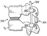
도 1은 본 발명의 하나의 구현예에 따른 후관절의 기능을 대체하는 후방장치 및 전방장치를 도시한다.1 shows a rear and anterior device for replacing the function of the posterior joint according to one embodiment of the present invention.
도 2A는 본 발명의 하나의 구현예에 따른 후관절의 기능을 대체하는 후방장치 및 전방장치를 도시한다.2A shows a rear and anterior device replacing the function of the posterior joint according to one embodiment of the present invention.
도 2B 및 2C는 일례의 후방장치를 도시한다.2B and 2C show an example rear device.
도 3은 본 발명의 하나의 구현예에 따른 후관절의 기능을 대체하는 후방장치 및 전방장치를 도시한다.3 shows a rear and anterior device for replacing the function of the posterior joint according to one embodiment of the present invention.
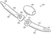
도 4는 본 발명의 하나의 구현예에 따른 후관절의 기능을 대체하는 후방장치의 요소를 도시한다.4 illustrates elements of the posterior device that replaces the function of the posterior joint according to one embodiment of the present invention.
도 5는 도 4의 조립된 후방장치를 도시한다.5 shows the assembled rear device of FIG. 4.
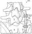
도 6 내지 8은 도 5의 후방장치의 사용방법의 일례를 도시한다.6 to 8 show an example of a method of using the rear device of FIG.
본 발명의 원리에 대한 이해를 증진시키기 위한 목적으로, 도면으로 도시된 구현예들, 즉 실시예들에 참조 부호를 붙이고, 이러한 것을 설명하기 위해 특수한 용어를 사용할 것이다. 그럼에도 불구하고 본 발명의 범위가 그것에 의해 한정되지 않는 것으로 이해되어야 한다. 추가로, 참조 부호들은 단일성을 위하여 반복되어 사용되며, 단독으로는, 다른 구현예에서 언급된 요소의 어떠한 조합도 나타내지 않는다. 설명된 구현예에서 임의의 변경 및 추가 변형, 및 본원에서 설명된 것과 같이 본 발명의 원리의 임의의 추가 적용들은 본 발명과 관계된 당해 기술 분야의 당업자에게 통상적으로 일어날 수 있는 것으로 예상될 수 있다.For the purpose of promoting an understanding of the principles of the present invention, reference is made to the embodiments illustrated in the drawings, i. Nevertheless, it should be understood that the scope of the present invention is not limited thereto. In addition, the reference signs are used repeatedly for the sake of unity and, alone, do not represent any combination of the elements mentioned in the other embodiments. Any modifications and additional variations in the described embodiments, and any further applications of the principles of the invention as described herein, can be expected to occur conventionally to one skilled in the art related to the invention.
하나의 실시예에서, 도 1을 참조하면, 두 개의 인접한 척추 V1 및 V2은 손상되거나 퇴화된 후관절(110)과 함께 도시된다. 본 구현예는 인공 후관절 장치와 같은 해부학적 임플란트를 반드시 필요로 하지 않으면서 상기 후관절(110)의 기능들(또는 몇몇의 기능)을 복제하고자 한다. 그러나, 해부학적 임플란트는 필요할 경우, 몇몇의 구현예에서 여전히 사용될 수 있음이 이해되어야 한다. 상기 후관절(110)의 기능을 대체하기 위하여, 후방장치(100) 및/또는 전방장치(120)가 이용된다. 상기 후방장치(100)는 상기 후관절(110)의 기능을 복제하기 위하여 상기 전방장치(120)와 함께 또는 단독으로 이용될 수 있다. 반대로, 전방장치(후방장치 없이)와 함께 스탠드(stand)가 상기 후관절의 기능을 복제하기 위해 사용될 수 있다.In one embodiment, referring to FIG. 1, two adjacent vertebrae V1 and V2 are shown with injured or degenerated
상기 후방장치(100) 및/또는 상기 전방장치(120)로 상기 후관절(110)의 기능을 수행하기 위하여, 상기 후관절(110)의 기능적 요건을 수치화하는 많은 방법들이 사용될 수 있다. 예를 들어, 상기 후관절(110)에 의하여 전달되는 척추 부하(spinal load)가 측정될 수 있다. 대안으로 또는 추가로, 상기 후관절(110)의 운동을 재현하는 설계 장치(design devices)를 이용하는 운동 분석 방법들이 이용될 수도 있다.Many methods of quantifying the functional requirements of the
상기 후관절(110)의 기능적 요건이 수치화되면, 상기 후방장치(100)의 구성물은 이러한 요건을 충족시키기 위해 선택될 수 있다. 예들은 형상 기억 합금(shape memory alloy), 케이블, 또는 스프링으로 구성된 장치와 같은 가요성 생체적합성 장치들을 포함한다. 도 1의 도면에서, 상기 후방장치(100)는 가요성 케이블이다. 본 구현예에서, 상기 후방장치(100)는 다양한 물리적 위치에 존재하며, 이로 인해 상기 장치가 상기 후관절(110)의 공간 및 형상 요건을 충족시키는 대신에 상기 기능적 요건을 충족시키는 크기로 만들어지도록 할 수 있다. 도 1의 이러한 도면에서, 상기 후방장치(100)는 척추경 나사(pedicle screws)와 같은 생체적합성 부착 장치(102 및 104)에 의하여 상기 척추 V1 및 V2의 척추경에 부착된다. 부착 장치들의 다른 실시예들은 스테이플(staples), 리벳(rivets), 상기 장치(100)의 고정 부분을 수용하는 척추에서 형성되는 고정 홈(locking grooves)을 포함한다. 또한 상기 후방장치(100)는 관절돌기, 횡돌기, 가시돌기, 또는 척추궁과 같은 상기 척추 V1 및 V2의 다른 부분에 부착될 수 있음을 예상할 수 있다. 테더(tethers), 스테이플, 및 다른 고정(anchoring) 장치들이 사용될 수 있음을 추가로 예상할 수 있다.Once the functional requirements of the
상기 후방장치(100)는 형상 기억 물질로 만들어진 가요성 케이블이 될 수 있으며, 그것은 고분자계(polymer-based) 또는 니티놀(Nitinol)이 될 수 있다. 예를 들어, 상기 후방장치(100)는 약 Ni 절반 및 Ti 절반을 포함할 수 있으며, 뜨거운 공기로 처리되고 나서 찬물로 처리되어 인체의 온도 범위보다 낮은 오스테나이트 마감 온도(austenite finish temperature)를 형성할 수 있다. 이러한 실시예에서, 상기 후방장치(100)는 약 34℃의 오스테나이트 마감 온도를 가질 수 있다. 따라서, 34℃ 위에서는, 상기 후방장치(100)는 초탄성(superelastic)이 된다.The
상기 후방장치(100)를 인체 내에 삽입하기에 앞서, 그것은 용이한 삽입을 위한 소정의 형상을 유지하도록 34℃ 아래로 냉각될 수 있다. 대안으로, 34℃ 보다 높은 온도로 유지되면, 그로 인해 그것의 초탄성이 삽입을 도울 수 있다. 상기 전방장치(120)는 상기 척추 V1 및 V2 사이의 디스크 공간으로 삽입될 수 있다. 도 1의 도면에서, 상기 전방장치(120)는 미국특허 제6,402,785호(SDGI Holdings, Inc.에 양도되고, 참조에 의하여 본원에 편입된)에 공개된 것 같은 디스크 대체 장치(disc replacement device)이다. 전방장치들(120)의 다른 예들은 형상 기억 합금으로 만들어진 케이블, 스프링, 또는 장치와 같은 가요성 생체적합성 장치들을 포함한다.Prior to inserting the
상기 후관절(110)의 상태에 따라, 그것은 외과 수술에 의해 제거되거나 제거되지 않을 수 있다. 예를 들어, 상기 후관절(110)이 심각한 고통을 일으킨다면, 그것은 반드시 제거될 것이다. 상기 후관절(110)은 원위치에 남을 수도 있으며 심지어 제한된 한도까지 이용될 수 있다.Depending on the condition of the posterior joint 110, it may or may not be removed by surgery. For example, if the hip joint 110 causes severe pain, it will necessarily be removed. The posterior joint 110 may remain in place and may even be used to a limited extent.
도 2A를 참조하면, 다른 구현예에서, 척추 V3 및 V4 사이의 후관절(204)은 손상되거나 퇴화될 수 있다. 그 결과, 단독으로, 또는 전방장치(202)와 함께 사용될 수 있는 후방장치(200)는, 상기 후관절(204)의 기능(또는 주기능)을 대체할 수 있다.Referring to FIG. 2A, in other embodiments, the posterior joint 204 between the vertebrae V3 and V4 may be damaged or degenerated. As a result, the
도 2B를 참조하면, 하나의 구현예에서, 상기 후방장치(200)는 한 쌍의 부착 장치(206 및 208), 바이어스(bias) 부재(210) 및 부착 하우징(housing attachment)(212)를 포함하는 생체적합성 스프링이 될 수 있다.Referring to FIG. 2B, in one embodiment, the
상기 부착 장치(206 및 208)는 코터(cotters), 리벳, 스파이크(spikes), 키(keys), 커플링(couplings), 또는 부싱(bushings)과 같은 임의의 종래 부착 장치를 포함할 수 있다. 이 도면에서, 상기 부착 장치(206 및 208)는 상기 후방장치(200)를 고정하기 위하여 상기 척추 V3 및 V4에 삽입될 수 있는 생체적합성 나사이다.The
상기 바이어스 부재(210)는 척추 운동에 따라 재형성될 수 있다. 종래의 스프링의 기능에 유사하게, 상기 바이어스 부재(210)는 상기 후관절(204)의 기능을 복제함으로써 척추 운동에 반응할 수 있다. 예를 들어, 상기 바이어스 부재(210)는 척추에 부과되는 부하만큼 가압될 수 있으나, 굴곡(flexion) 운동을 하는 동안 연장될 수 있다. 상기 바이어스 부재(210)는 선택된 물질 및 구조에 따라 결정되는 탄성 범위(elastic range) 내에서 작동할 수 있음을 예상할 수 있다. 상기 바이어스 부재(210)가 티타늄, 카본 파이버(carbon fiber), 중합체(polymers), 또는 형상 기억 합금과 같은 임의의 생체적합성 물질을 포함할 수 있음을 추가로 예상할 수 있다.The
상기 부착 하우징(212)은 주변 조직의 간섭으로부터 상기 바이어스 부재(210)를 보호하기 위하여 사용될 수 있으며, 그로 인해 상기 조직들이 우연히 상기 바이어스 부재(210)를 방해할 수 없으며 적절한 기능을 방해할 수 없다. 상기 부착 하우징(212)은 고무 또는 형상 기억 합금과 같은 임의의 생체적합성 물질을 포함할 수 있음을 예상할 수 있다.The
상기 후방장치(200) 및 그 요소는 도 2C에 도시된 것과 같은 다양한 형상을 포함할 수 있음을 예상할 수 있다. 상기 후방장치(200)가 다수의 바이어스 부재들을 포함할 수 있거나, 단순히 종래의 스프링임을 추가로 예상할 수 있다. 또한 상기 후방장치(200)가 형상 기억 합금으로 만들어진 케이블, 또는 장치와 같은 임의의 가요성 생체적합성 장치임을 예상할 수 있다.It is envisioned that the
상기 후방장치(200)는 핀(pins), 커낵터, 코터, 리벳, 스파이크, 키, 커플링, 부싱, 와셔(washers), 또는 다른 고정 장치와 같은 임의의 종래의 생체적합성 부착 장치들에 의하여 상기 척추 V3 및 V4의 횡돌기에 부착될 수 있다. 또한 상기 후방장치(200)는 상기 척추 V3 및 V4의 척추경, 관절돌기, 가시돌기, 또는 척추궁에 부착될 수 있음을 예상할 수 있다.The
핵 장치(nucleus device)가 될 수 있는 상기 전방장치(202)는 상기 척추 V3 및 V4 사이의 디스크 공간으로 삽입될 수 있으며, 상기 후관절(204)의 기능을 대체하기 위하여 상기 후방장치(200)와 함께 작동할 수 있다. 상기 전방장치(202)는 임의의 종래 핵 대체 장치(nucleus replacement devices)를 포함할 수 있다. 그것은 형상 기억 합금으로 만들어진 케이블, 스프링, 또는 장치와 같은 임의의 가요성 생체적합성 장치를 포함할 수도 있다. 종래 핵 대체 장치들은 본 발명이 속하는 기술분야에서 알려져 있으므로, 본원에서 추가로 설명하지 않을 것임이 이해되어야 한다.The
디스크 관절(204)의 상태에 따라, 디스크 관절은 외과 수술에 의해 제거되거나 제거되지 않을 수 있다. 예를 들어, 상기 디스크 관절(204)이 심각한 고통을 일으킨다면, 그것은 외과 수술에 의해 제거될 수 있다. 실질적으로 그의 기능에 의존함 없이, 그것은 동물체(animal body)에 남을 수도 있다.Depending on the state of the disc joint 204, the disc joint may or may not be removed by surgical surgery. For example, if the disc joint 204 causes severe pain, it can be removed by surgical surgery. Indeed, depending on its function, it may remain in the animal body.
도 3을 참조하면, 또 다른 구현예에서는, 후방장치(302) 및 후방장치(304)의 조합이 척추 V5 및 V6 사이의 손상된 후관절(보이지 않음)의 기능들(또는 주기능)을 대체하기 위하여 사용될 수 있다. 또한 앞서 설명된 장치(108 또는 202)과 유사한 전방장치(310)는 후관절 기능을 대체하기 위하여 상기 후방장치(302 및 304)와 함께 기능할 수 있음을 예상할 수 있다.Referring to FIG. 3, in another embodiment, the combination of the
상기 후방장치(302) 및 상기 후방장치(304)는 상기 후관절의 기능을 복제함에 있어 서로 상보적인 기능을 할 수 있다. 예를 들어, 상기 후방장치(302)는 대체된 후관절 기능의 능력을 조절하는 생체적합성 스프링이 될 수 있는 반면에, 상기 후방장치(304)는 대체된 후관절 기능의 움직임을 조절하는 댐퍼(damper)가 될 수 있다. 상기 후방장치(302)는 앞서 설명된 후방장치(100 또는 200) 중 어느 하나, 또는 생체적합성 댐퍼가 될 수 있다. 이와 마찬가지로, 상기 후방장치(304)는 앞서 설명된 후방장치(100 또는 200) 중 어느 하나가 될 수 있다. 하나의 실시예에서, 상기 후방장치(304)는 발명의 명칭이 "충격흡수장치(Shock-Absorbing Device)"인 미국특허 제2,235,488호에 공개된 구현예와 동일하거나 유사한 댐퍼(damper)가 될 수 있는데, 이것은 참조에 의하여 본원에 편입된다.The
이러한 실시예에서, 상기 후방장치(302)는 척추경 나사에 의해서 척추경에 부착될 수 있는 반면, 상기 후방장치(304)는 상기 척추 V5 및 V6의 횡돌기에 부착될 수 있다. 각각의 상기 후방장치들(302 및 304)은 상기 척추 V5 및 V6의 임의의 관절돌기, 횡돌기, 가시돌기, 척추궁, 또는 척추경에 부착될 수도 있다. 하나 이상의 추가적인 후방장치들이 상기 후방장치들(302 및 304)에 추가될 수 있으며, 모든 것들이 후관절 기능을 대체하기 위해 함께 작용할 수 있음을 예상할 수 있다.In this embodiment, the
비록 상기 구현예들이 단일 후관절의 기능을 대체하는 것에 관한 것일지라도, 본 발명은 다수의 후관절의 기능을 대체하기 위하여 적용될 수 있음이 예상할 수 있다. 예를 들어, 양쪽 접근(bilateral approach)은 디스크의 양 측면에서 손상된 후관절을 대체하기 위해 채용될 수 있다.Although the above embodiments relate to replacing the function of a single facet, it can be expected that the present invention can be applied to replace the function of multiple facet joints. For example, a bilateral approach can be employed to replace a damaged facet joint on both sides of the disc.
도 4를 참조하면, 다른 구현예에서, 후방장치(400)는 커낵터(418), 제 1 요소(420), 및 제 2 요소(422)를 포함할 수 있다. 상기 후방장치(400)는 어떠한 해부학적 후관절 임플란트의 사용 없이 후관절의 기능을 대체하기 위하여 단독으로, 또는 앞에서 설명된 하나 이상의 부가적인 후방 및/또는 전방장치들과 함께 사용될 수 있다. 상기 후방장치(400)는 앞서 설명된 구현예들에서 임의의 상기 후방장치들(100, 200, 302 또는 304)을 대체하기 위하여 사용될 수 있음을 예상할 수 있다.Referring to FIG. 4, in another embodiment, the
상기 커낵터(418)는 후관절의 기능을 모방하는 운동을 허용하기 위하여 상기 후방장치(400)에 탄성(elasticity)을 제공한다. 상기 커낵터(418)는, 고무, 실리콘 또는 형상 기억 합금과 같은 임의의 탄성의 생체적합성 물질을 포함할 수 있다. 그것은 임의의 적절한 형상을 포함할 수 있는데, 그것은 속이 빈 올리브 또는 불완전한 구(partial sphere)가 될 수 있다.The
상기 제 1 요소(420)는 팁(408), 로드(rod) 또는 샤프트(shaft)가 될 수 있는 긴 본체(406), 및 조인트(402)를 포함할 수 있다. 상기 팁(408)은 뾰족하여, 상기 후방장치(400)의 경피주입(percutaneous insertion)에 적합한데, 그것은 동물체의 조직을 통과하여 상기 후방장치(400)를 밀어 넣을 수 있게 할 수 있다. 상기 조인트(402)는 개구부(404)를 포함하는데, 상기 후방장치(400)의 운동을 촉진시키기 위하여 고무, 실리콘 또는 형상 기억 합금과 같은 임의의 생체적합성 탄성 재료를 포함할 수 있다.The
상기 제 2 요소(422)는 상기 제 1 요소(420)의 구조와 동일하거나 유사한 구조를 가질 수 있다. 이 도면에서, 상기 제 2 요소(422)는 팁(416), 로드 또는 샤프트가 될 수 있는 긴 본체(414), 및 조인트(410)를 포함할 수 있다. 상기 팁(416)은 뾰족하여, 상기 후방장치(400)의 경피주입에 적합한데, 그것은 동물체의 조직을 통과하여 상기 후방장치(400)를 밀어 넣을 수 있게 할 수 있다. 상기 조인트(410)는 개구부(412)를 포함하는데, 상기 후방장치(400)의 운동을 촉진시키기 위하여 고무, 실리콘 또는 형상 기억 합금과 같은 임의의 생체적합성 탄성 재료를 포함할 수 있다. 상기 개구부(412)는 상기 개구부(404)와 결합되어, 두 개구부(404 및 412)를 통하여 탄성 재료를 흐르게 하여 상기 후방장치(400)의 기능을 촉진하기 할 수 있다. 또한 상기 제 2 요소(422)는 상기 제 1 요소(420)의 구조와 다른 구조를 가질 수 있음을 예상할 수 있다.The
상기 제 1 및 제 2 요소(420 및 422)는 그들의 각각의 조인트(402 및 410)를 통하여 함께 만들어지거나 나사로 고정되는 것과 같은 임의의 종래 수단에 의하여 함께 결합되어, 하나의 유닛을 형성할 수 있다. 추가로, 그것들은 후관절의 본래의 해부학적 구조와 유사하게 하기 위하여 다른 각도로 결합될 수 있다. 예를 들어, 목부위에서 후관절의 기능을 대체하기 위하여, 상기 제 1 및 제 2 요소(420 및 422)는 자연 후관절의 방향을 모의하기 위하여 수평에 대해 약 45°에서 결합될 수 있다. 다른 실시예에서, 흉부위(thoracic region)에서 후관절의 기능을 대체하기 위하여, 상기 제 1 및 제 2 요소(420 및 422)는 인체의 축면(axial plane)에 대해 약 60° 및 관상면(frontal plane)에 대해 20°의 각도로 결합될 수 있다. 허리영역에서, 상기 제 1 및 제 2 요소(420 및 422)는 인체의 축면에 대해 약 90° 및 관상면에 대해 45°의 각도로 연결될 수 있다.The first and
각각의 상기 제 1 및 제 2 요소(420 및 422)는 강철, 티타늄, 형상 기억 합금, 중합체, 카본 파이버, 및 다공성 물질(porous material)과 같은 임의의 생체적합성 물질을 포함할 수 있다. 상기 후방장치(400)는 척추의 임의의 척추경, 관절돌기, 횡돌기, 가시돌기, 또는 척추궁에 부착될 수 있음을 예상할 수 있다.Each of the first and
도 5를 참조하면, 상기 후방장치(400)는 후방 또는 외측 접근법(lateral approach)과 같은 임의의 종래 접근법에 의해 척추부위에 하나의 유닛으로 삽입될 수 있다. 또한 상기 후방장치(400)는 미국특허 제6,530,929호(SDGI Holdings, Inc.에 양도된)에 공개된 접근법에 의하여 척추부위에 삽입될 수 있음을 예상할 수 있다.Referring to FIG. 5, the
상기 후방장치들(100, 200, 302, 304 및 400)의 이용에 대해 설명한다. 상기 후방장치(들)는 후방 또는 외측 접근법과 같은 임의의 종래 접근법에 의해 척추부위에 삽입될 수 있다. 예를 들어, 후방에서 접근하기에 유용한 과정들 및 장치들은 미국특허 제6,241,729호(SDGI Holdings, Inc.에 양도된), 및 "후방 접근용 뼈 접합 기구(Bone Dowel Instrumentation)를 사용하는 수술 기법"이라는 명칭의 Sofamor Danekⓒ1996에 의한 문헌에 공개되어 있으며, 각각은 전부 참조에 의하여 본원에 편입된다. 또한 임의의 상기 후방장치들(100, 200, 302, 304, 및 400)은 미국특허 제6,530,929호(SDGI Holdings, Inc.에 양도되며, 참조에 의하여 본원에 편입된)에 공개된 접근법에 의하여 척추부위에 삽입될 수 있음을 예상할 수 있다.The use of the
상기 전방장치들(120, 202 및 303)은 전방, 후방 또는 외측 접근법과 같은 임의의 종래 접근법에 의하여 척추부위에 삽입될 수 있다. 예를 들어, 전방에서 접근하기에 유용한 과정들 및 장치들은 미국특허 제6,428,541호 (SDGI Holdings, Inc.에 양도된), 및 "전방 접근용 뼈 접합 기구(Bone Dowel Instrumentation)를 사용하는 수술 기법"이라는 명칭의 Sofamor Danekⓒ1996에 의한 문헌에 공개되어 있으며, 각각은 전부 참조에 의하여 본원에 편입된다.The
도 6 내지 8은 동물체의 척추에 부착된 상태의 상기 후방장치(400)의 사용방법의 일례를 도시한다. 예를 들어, 도 6을 참조하면, 본 발명의 하나의 구현예에 따른 두 개의 다축나사(multi-axial screws)(602 및 604)에 의해 척추 V7, V8 사이에 위치하는 상기 후방장치(400)를 보여준다. 사용될 수 있는 부착 메카니즘의 추가적인 예들은 미국특허 제6,280,442호, 제5,891,145호, 제6,485,491호, 및 제6,520,963호에 공개되어 있으며, 각각은 참조에 의하여 본원에 편입된다. 도 7 및 8은 본 발명의 하나의 구현예에 따른 상기 후방장치(400)의 구현을 보여주기 위한 다른 각도로부터 도 6의 사시도를 도시한다.6 to 8 show an example of how to use the
비록 오직 몇 가지의 전형적인 본 발명의 구현예들은 위에서 상세하게 설명되었지만, 본 발명의 신규한 공지 및 이점들로부터 현저히 벗어남 없이 전형적인 구현예들에서 많은 변형들이 가능함을 본 발명이 속하는 기술 분야의 당업자들은 쉽게 이해할 수 있다. 또한, 몇몇의 구현예들과 관련해서 위에서 도시되고 설명된 특징들은 다른 구현예들과 관련해서 위에서 도시되고 설명된 특징들과 결합될 수 있다. 예를 들어, 척추돌기(spinal process)에 고정되는 부착 메카니즘들은 필요할 경우, 척추경 또는 척추궁에 고정될 수도 있다. 따라서, 모든 그러한 변형 및 대안은 청구된 발명의 범위 내에 포함되는 것으로 의도된다.Although only a few typical embodiments of the present invention have been described in detail above, those skilled in the art to which the present invention pertains can make many modifications to the exemplary embodiments without departing from the novel disclosure and advantages of the present invention. It is easy to understand. In addition, the features shown and described above in connection with some embodiments may be combined with the features shown and described above in connection with other embodiments. For example, attachment mechanisms that are secured to the spinal process may be secured to the pedicle or spinal arch as needed. Accordingly, all such modifications and alternatives are intended to be included within the scope of the claimed invention.
Claims (22)
Translated fromKoreanApplications Claiming Priority (2)
| Application Number | Priority Date | Filing Date | Title |
|---|---|---|---|
| US10/733,554US7553320B2 (en) | 2003-12-10 | 2003-12-10 | Method and apparatus for replacing the function of facet joints |
| US10/733,554 | 2003-12-10 |
Publications (1)
| Publication Number | Publication Date |
|---|---|
| KR20060105882Atrue KR20060105882A (en) | 2006-10-11 |
Family
ID=34653116
Family Applications (1)
| Application Number | Title | Priority Date | Filing Date |
|---|---|---|---|
| KR1020067013722AWithdrawnKR20060105882A (en) | 2003-12-10 | 2004-12-01 | Method and apparatus for replacing the function of facet joints |
Country Status (8)
| Country | Link |
|---|---|
| US (2) | US7553320B2 (en) |
| EP (1) | EP1703868A1 (en) |
| JP (1) | JP2007513694A (en) |
| KR (1) | KR20060105882A (en) |
| CN (1) | CN1921808A (en) |
| AU (1) | AU2004305548A1 (en) |
| CA (1) | CA2548911A1 (en) |
| WO (1) | WO2005060879A1 (en) |
Families Citing this family (190)
| Publication number | Priority date | Publication date | Assignee | Title |
|---|---|---|---|---|
| US7833250B2 (en) | 2004-11-10 | 2010-11-16 | Jackson Roger P | Polyaxial bone screw with helically wound capture connection |
| US7862587B2 (en) | 2004-02-27 | 2011-01-04 | Jackson Roger P | Dynamic stabilization assemblies, tool set and method |
| US8292926B2 (en) | 2005-09-30 | 2012-10-23 | Jackson Roger P | Dynamic stabilization connecting member with elastic core and outer sleeve |
| US8353932B2 (en) | 2005-09-30 | 2013-01-15 | Jackson Roger P | Polyaxial bone anchor assembly with one-piece closure, pressure insert and plastic elongate member |
| US10729469B2 (en) | 2006-01-09 | 2020-08-04 | Roger P. Jackson | Flexible spinal stabilization assembly with spacer having off-axis core member |
| US10258382B2 (en) | 2007-01-18 | 2019-04-16 | Roger P. Jackson | Rod-cord dynamic connection assemblies with slidable bone anchor attachment members along the cord |
| US8876868B2 (en) | 2002-09-06 | 2014-11-04 | Roger P. Jackson | Helical guide and advancement flange with radially loaded lip |
| US7101398B2 (en)* | 2002-12-31 | 2006-09-05 | Depuy Acromed, Inc. | Prosthetic facet joint ligament |
| US20050055096A1 (en)* | 2002-12-31 | 2005-03-10 | Depuy Spine, Inc. | Functional spinal unit prosthetic |
| US7621918B2 (en) | 2004-11-23 | 2009-11-24 | Jackson Roger P | Spinal fixation tool set and method |
| US8652175B2 (en)* | 2003-05-02 | 2014-02-18 | Rachiotek, Llc | Surgical implant devices and systems including a sheath member |
| US7377923B2 (en) | 2003-05-22 | 2008-05-27 | Alphatec Spine, Inc. | Variable angle spinal screw assembly |
| US7766915B2 (en) | 2004-02-27 | 2010-08-03 | Jackson Roger P | Dynamic fixation assemblies with inner core and outer coil-like member |
| US8926670B2 (en) | 2003-06-18 | 2015-01-06 | Roger P. Jackson | Polyaxial bone screw assembly |
| US7776067B2 (en) | 2005-05-27 | 2010-08-17 | Jackson Roger P | Polyaxial bone screw with shank articulation pressure insert and method |
| US7967850B2 (en) | 2003-06-18 | 2011-06-28 | Jackson Roger P | Polyaxial bone anchor with helical capture connection, insert and dual locking assembly |
| US8366753B2 (en) | 2003-06-18 | 2013-02-05 | Jackson Roger P | Polyaxial bone screw assembly with fixed retaining structure |
| US7588590B2 (en) | 2003-12-10 | 2009-09-15 | Facet Solutions, Inc | Spinal facet implant with spherical implant apposition surface and bone bed and methods of use |
| US20050131406A1 (en)* | 2003-12-15 | 2005-06-16 | Archus Orthopedics, Inc. | Polyaxial adjustment of facet joint prostheses |
| US11419642B2 (en) | 2003-12-16 | 2022-08-23 | Medos International Sarl | Percutaneous access devices and bone anchor assemblies |
| US7527638B2 (en) | 2003-12-16 | 2009-05-05 | Depuy Spine, Inc. | Methods and devices for minimally invasive spinal fixation element placement |
| US7179261B2 (en) | 2003-12-16 | 2007-02-20 | Depuy Spine, Inc. | Percutaneous access devices and bone anchor assemblies |
| US8029548B2 (en) | 2008-05-05 | 2011-10-04 | Warsaw Orthopedic, Inc. | Flexible spinal stabilization element and system |
| US9451990B2 (en)* | 2004-02-17 | 2016-09-27 | Globus Medical, Inc. | Facet joint replacement instruments and methods |
| US8562649B2 (en) | 2004-02-17 | 2013-10-22 | Gmedelaware 2 Llc | System and method for multiple level facet joint arthroplasty and fusion |
| US8333789B2 (en) | 2007-01-10 | 2012-12-18 | Gmedelaware 2 Llc | Facet joint replacement |
| JP2007525274A (en) | 2004-02-27 | 2007-09-06 | ロジャー・ピー・ジャクソン | Orthopedic implant rod reduction instrument set and method |
| US8152810B2 (en) | 2004-11-23 | 2012-04-10 | Jackson Roger P | Spinal fixation tool set and method |
| US11241261B2 (en) | 2005-09-30 | 2022-02-08 | Roger P Jackson | Apparatus and method for soft spinal stabilization using a tensionable cord and releasable end structure |
| US7160300B2 (en) | 2004-02-27 | 2007-01-09 | Jackson Roger P | Orthopedic implant rod reduction tool set and method |
| US8523904B2 (en) | 2004-03-09 | 2013-09-03 | The Board Of Trustees Of The Leland Stanford Junior University | Methods and systems for constraint of spinous processes with attachment |
| US7458981B2 (en)* | 2004-03-09 | 2008-12-02 | The Board Of Trustees Of The Leland Stanford Junior University | Spinal implant and method for restricting spinal flexion |
| US7507242B2 (en) | 2004-06-02 | 2009-03-24 | Facet Solutions | Surgical measurement and resection framework |
| US7854752B2 (en) | 2004-08-09 | 2010-12-21 | Theken Spine, Llc | System and method for dynamic skeletal stabilization |
| WO2006016371A2 (en)* | 2004-08-13 | 2006-02-16 | Mazor Surgical Technologies Ltd | Minimally invasive spinal fusion |
| US7651502B2 (en) | 2004-09-24 | 2010-01-26 | Jackson Roger P | Spinal fixation tool set and method for rod reduction and fastener insertion |
| US8267969B2 (en) | 2004-10-20 | 2012-09-18 | Exactech, Inc. | Screw systems and methods for use in stabilization of bone structures |
| US7935134B2 (en) | 2004-10-20 | 2011-05-03 | Exactech, Inc. | Systems and methods for stabilization of bone structures |
| US8162985B2 (en) | 2004-10-20 | 2012-04-24 | The Board Of Trustees Of The Leland Stanford Junior University | Systems and methods for posterior dynamic stabilization of the spine |
| US8226690B2 (en)* | 2005-07-22 | 2012-07-24 | The Board Of Trustees Of The Leland Stanford Junior University | Systems and methods for stabilization of bone structures |
| US8025680B2 (en)* | 2004-10-20 | 2011-09-27 | Exactech, Inc. | Systems and methods for posterior dynamic stabilization of the spine |
| AU2005302633A1 (en)* | 2004-10-28 | 2006-05-11 | Axial Biotech, Inc. | Apparatus and method for concave scoliosis expansion |
| US8926672B2 (en) | 2004-11-10 | 2015-01-06 | Roger P. Jackson | Splay control closure for open bone anchor |
| US9216041B2 (en) | 2009-06-15 | 2015-12-22 | Roger P. Jackson | Spinal connecting members with tensioned cords and rigid sleeves for engaging compression inserts |
| US9168069B2 (en) | 2009-06-15 | 2015-10-27 | Roger P. Jackson | Polyaxial bone anchor with pop-on shank and winged insert with lower skirt for engaging a friction fit retainer |
| WO2006057837A1 (en) | 2004-11-23 | 2006-06-01 | Jackson Roger P | Spinal fixation tool attachment structure |
| US8444681B2 (en) | 2009-06-15 | 2013-05-21 | Roger P. Jackson | Polyaxial bone anchor with pop-on shank, friction fit retainer and winged insert |
| US7901437B2 (en) | 2007-01-26 | 2011-03-08 | Jackson Roger P | Dynamic stabilization member with molded connection |
| WO2006116119A2 (en)* | 2005-04-21 | 2006-11-02 | Spine Wave, Inc. | Dynamic stabilization system for the spine |
| US20060264937A1 (en)* | 2005-05-04 | 2006-11-23 | White Patrick M | Mobile spine stabilization device |
| JP4907908B2 (en)* | 2005-06-29 | 2012-04-04 | ルネサスエレクトロニクス株式会社 | Driving circuit and display device |
| US8147521B1 (en)* | 2005-07-20 | 2012-04-03 | Nuvasive, Inc. | Systems and methods for treating spinal deformities |
| US8523865B2 (en) | 2005-07-22 | 2013-09-03 | Exactech, Inc. | Tissue splitter |
| FR2889438B1 (en)* | 2005-08-04 | 2008-06-06 | Scient X Sa | DOUBLE-SHAPED INTERVERTEBRAL IMPLANT |
| US7799057B2 (en)* | 2005-09-02 | 2010-09-21 | Zimmer Spine, Inc. | Translaminar facet augmentation and flexible spinal stabilization |
| US7993376B2 (en)* | 2005-09-29 | 2011-08-09 | Depuy Spine, Inc. | Methods of implanting a motion segment repair system |
| US8105368B2 (en) | 2005-09-30 | 2012-01-31 | Jackson Roger P | Dynamic stabilization connecting member with slitted core and outer sleeve |
| US20070093813A1 (en)* | 2005-10-11 | 2007-04-26 | Callahan Ronald Ii | Dynamic spinal stabilizer |
| US20070093815A1 (en)* | 2005-10-11 | 2007-04-26 | Callahan Ronald Ii | Dynamic spinal stabilizer |
| US20070093814A1 (en)* | 2005-10-11 | 2007-04-26 | Callahan Ronald Ii | Dynamic spinal stabilization systems |
| EP1943987B1 (en)* | 2005-10-26 | 2012-04-18 | BIEDERMANN MOTECH GmbH | Implant with one-piece swivel joint |
| US8357181B2 (en) | 2005-10-27 | 2013-01-22 | Warsaw Orthopedic, Inc. | Intervertebral prosthetic device for spinal stabilization and method of implanting same |
| WO2007061960A2 (en) | 2005-11-18 | 2007-05-31 | Life Spine, Inc. | Dynamic spinal stabilization devices and systems |
| US20070198091A1 (en)* | 2005-12-06 | 2007-08-23 | Boyer Michael L | Facet joint prosthesis |
| DE102005061368B3 (en)* | 2005-12-13 | 2007-07-12 | Aesculap Ag & Co. Kg | Implantable connecting element and surgical fixation system |
| US20070168038A1 (en)* | 2006-01-13 | 2007-07-19 | Sdgi Holdings, Inc. | Materials, devices and methods for treating multiple spinal regions including the interbody region |
| US20070173822A1 (en)* | 2006-01-13 | 2007-07-26 | Sdgi Holdings, Inc. | Use of a posterior dynamic stabilization system with an intradiscal device |
| US20070173820A1 (en)* | 2006-01-13 | 2007-07-26 | Sdgi Holdings, Inc. | Materials, devices, and methods for treating multiple spinal regions including the anterior region |
| US20070168041A1 (en)* | 2006-01-17 | 2007-07-19 | Sudhakar Kadiyala | Method and instruments for intervertebral disc augmentation through a pedicular approach |
| CN100534398C (en)* | 2006-02-09 | 2009-09-02 | 邹德威 | Coupling full intervertebral joints system |
| US20070213718A1 (en)* | 2006-02-14 | 2007-09-13 | Sdgi Holdings, Inc. | Treatment of the vertebral column |
| US20070227547A1 (en)* | 2006-02-14 | 2007-10-04 | Sdgi Holdings, Inc. | Treatment of the vertebral column |
| US7520888B2 (en)* | 2006-02-14 | 2009-04-21 | Warsaw Orthopedic, Inc. | Treatment of the vertebral column |
| US20070233091A1 (en)* | 2006-02-23 | 2007-10-04 | Naifeh Bill R | Multi-level spherical linkage implant system |
| US8025681B2 (en) | 2006-03-29 | 2011-09-27 | Theken Spine, Llc | Dynamic motion spinal stabilization system |
| US20070270959A1 (en)* | 2006-04-18 | 2007-11-22 | Sdgi Holdings, Inc. | Arthroplasty device |
| US8012179B2 (en)* | 2006-05-08 | 2011-09-06 | Warsaw Orthopedic, Inc. | Dynamic spinal stabilization members and methods |
| US20080058808A1 (en) | 2006-06-14 | 2008-03-06 | Spartek Medical, Inc. | Implant system and method to treat degenerative disorders of the spine |
| US7766942B2 (en)* | 2006-08-31 | 2010-08-03 | Warsaw Orthopedic, Inc. | Polymer rods for spinal applications |
| US11195163B2 (en) | 2006-09-01 | 2021-12-07 | Mastercard International Incorporated | Methods, systems and computer readable media for over the air (OTA) provisioning of soft cards on devices with wireless communications capabilities |
| FR2913329B3 (en)* | 2006-10-06 | 2009-05-08 | Henry Graf | INTERVERTEBRAL STABILIZATION ASSEMBLY |
| US8029541B2 (en)* | 2006-10-19 | 2011-10-04 | Simpirica Spine, Inc. | Methods and systems for laterally stabilized constraint of spinous processes |
| ES2364417T3 (en)* | 2006-10-19 | 2011-09-01 | The Board Of Trustees Of The Leland Stanford Junior University | SYSTEMS FOR THE LIMITATION OF SPINE APOPHYSIS WITH CLAMPS. |
| US8187307B2 (en)* | 2006-10-19 | 2012-05-29 | Simpirica Spine, Inc. | Structures and methods for constraining spinal processes with single connector |
| US8162982B2 (en)* | 2006-10-19 | 2012-04-24 | Simpirica Spine, Inc. | Methods and systems for constraint of multiple spine segments |
| US8096996B2 (en) | 2007-03-20 | 2012-01-17 | Exactech, Inc. | Rod reducer |
| US20080140202A1 (en)* | 2006-12-08 | 2008-06-12 | Randall Noel Allard | Energy-Storing Spinal Implants and Methods of Use |
| CA2670988C (en) | 2006-12-08 | 2014-03-25 | Roger P. Jackson | Tool system for dynamic spinal implants |
| US8075596B2 (en)* | 2007-01-12 | 2011-12-13 | Warsaw Orthopedic, Inc. | Spinal prosthesis systems |
| US8475498B2 (en) | 2007-01-18 | 2013-07-02 | Roger P. Jackson | Dynamic stabilization connecting member with cord connection |
| US8366745B2 (en) | 2007-05-01 | 2013-02-05 | Jackson Roger P | Dynamic stabilization assembly having pre-compressed spacers with differential displacements |
| US7931676B2 (en)* | 2007-01-18 | 2011-04-26 | Warsaw Orthopedic, Inc. | Vertebral stabilizer |
| US20090105762A1 (en)* | 2007-10-23 | 2009-04-23 | Jackson Roger P | Dynamic stabilization member with fin supported segment |
| US8097022B2 (en)* | 2007-02-20 | 2012-01-17 | Warsaw Orthopedic, Inc. | Flexible coupling members for spinal stabilization members |
| US7842074B2 (en) | 2007-02-26 | 2010-11-30 | Abdou M Samy | Spinal stabilization systems and methods of use |
| FR2913328A1 (en)* | 2007-03-09 | 2008-09-12 | Henry Graf | Intervertebral dynamic stabilization assembly for arthrodesis of adjacent vertebrae, has elastic units interacting until equilibrium point is found, where point is controlled by external forces e.g. patient weight of and muscle contraction |
| US20080269805A1 (en) | 2007-04-25 | 2008-10-30 | Warsaw Orthopedic, Inc. | Methods for correcting spinal deformities |
| US10383660B2 (en) | 2007-05-01 | 2019-08-20 | Roger P. Jackson | Soft stabilization assemblies with pretensioned cords |
| US8979904B2 (en) | 2007-05-01 | 2015-03-17 | Roger P Jackson | Connecting member with tensioned cord, low profile rigid sleeve and spacer with torsion control |
| US8048128B2 (en) | 2007-06-05 | 2011-11-01 | Spartek Medical, Inc. | Revision system and method for a dynamic stabilization and motion preservation spinal implantation system and method |
| US8092501B2 (en) | 2007-06-05 | 2012-01-10 | Spartek Medical, Inc. | Dynamic spinal rod and method for dynamic stabilization of the spine |
| US8048123B2 (en) | 2007-06-05 | 2011-11-01 | Spartek Medical, Inc. | Spine implant with a deflection rod system and connecting linkages and method |
| US8109970B2 (en) | 2007-06-05 | 2012-02-07 | Spartek Medical, Inc. | Deflection rod system with a deflection contouring shield for a spine implant and method |
| US8114134B2 (en) | 2007-06-05 | 2012-02-14 | Spartek Medical, Inc. | Spinal prosthesis having a three bar linkage for motion preservation and dynamic stabilization of the spine |
| US8083772B2 (en) | 2007-06-05 | 2011-12-27 | Spartek Medical, Inc. | Dynamic spinal rod assembly and method for dynamic stabilization of the spine |
| US8052722B2 (en) | 2007-06-05 | 2011-11-08 | Spartek Medical, Inc. | Dual deflection rod system for a dynamic stabilization and motion preservation spinal implantation system and method |
| US8048115B2 (en) | 2007-06-05 | 2011-11-01 | Spartek Medical, Inc. | Surgical tool and method for implantation of a dynamic bone anchor |
| US8021396B2 (en) | 2007-06-05 | 2011-09-20 | Spartek Medical, Inc. | Configurable dynamic spinal rod and method for dynamic stabilization of the spine |
| US20110172708A1 (en)* | 2007-06-22 | 2011-07-14 | Simpirica Spine, Inc. | Methods and systems for increasing the bending stiffness of a spinal segment with elongation limit |
| EP2182864B1 (en)* | 2007-06-22 | 2016-06-08 | Empirical Spine, Inc. | Devices for controlled flexion restriction of spinal segments |
| US20100036424A1 (en) | 2007-06-22 | 2010-02-11 | Simpirica Spine, Inc. | Methods and systems for increasing the bending stiffness and constraining the spreading of a spinal segment |
| US8080038B2 (en)* | 2007-08-17 | 2011-12-20 | Jmea Corporation | Dynamic stabilization device for spine |
| US20090088803A1 (en)* | 2007-10-01 | 2009-04-02 | Warsaw Orthopedic, Inc. | Flexible members for correcting spinal deformities |
| JP5188792B2 (en)* | 2007-12-04 | 2013-04-24 | 株式会社ニデック | Visual reproduction assist device |
| US9232968B2 (en) | 2007-12-19 | 2016-01-12 | DePuy Synthes Products, Inc. | Polymeric pedicle rods and methods of manufacturing |
| WO2009092961A2 (en)* | 2008-01-15 | 2009-07-30 | Henry Graf | Intervertebral stabilization assembly for arthrodesis, comprising an impaction cage body, and an ancillary device for implanting same |
| US8088163B1 (en) | 2008-02-06 | 2012-01-03 | Kleiner Jeffrey B | Tools and methods for spinal fusion |
| US8211155B2 (en) | 2008-02-26 | 2012-07-03 | Spartek Medical, Inc. | Load-sharing bone anchor having a durable compliant member and method for dynamic stabilization of the spine |
| US8337536B2 (en) | 2008-02-26 | 2012-12-25 | Spartek Medical, Inc. | Load-sharing bone anchor having a deflectable post with a compliant ring and method for stabilization of the spine |
| US8083775B2 (en) | 2008-02-26 | 2011-12-27 | Spartek Medical, Inc. | Load-sharing bone anchor having a natural center of rotation and method for dynamic stabilization of the spine |
| US8267979B2 (en) | 2008-02-26 | 2012-09-18 | Spartek Medical, Inc. | Load-sharing bone anchor having a deflectable post and axial spring and method for dynamic stabilization of the spine |
| US8007518B2 (en) | 2008-02-26 | 2011-08-30 | Spartek Medical, Inc. | Load-sharing component having a deflectable post and method for dynamic stabilization of the spine |
| US8333792B2 (en) | 2008-02-26 | 2012-12-18 | Spartek Medical, Inc. | Load-sharing bone anchor having a deflectable post and method for dynamic stabilization of the spine |
| US8097024B2 (en) | 2008-02-26 | 2012-01-17 | Spartek Medical, Inc. | Load-sharing bone anchor having a deflectable post and method for stabilization of the spine |
| US8048125B2 (en) | 2008-02-26 | 2011-11-01 | Spartek Medical, Inc. | Versatile offset polyaxial connector and method for dynamic stabilization of the spine |
| US8057517B2 (en) | 2008-02-26 | 2011-11-15 | Spartek Medical, Inc. | Load-sharing component having a deflectable post and centering spring and method for dynamic stabilization of the spine |
| CA2717610A1 (en)* | 2008-03-06 | 2009-09-11 | Synthes Usa, Llc | Facet interference screw |
| US20090259257A1 (en)* | 2008-04-15 | 2009-10-15 | Warsaw Orthopedic, Inc. | Pedicule-Based Motion- Preserving Device |
| US8430912B2 (en)* | 2008-05-05 | 2013-04-30 | Warsaw Orthopedic, Inc. | Dynamic stabilization rod |
| US20210378834A1 (en) | 2008-05-22 | 2021-12-09 | Spinal Surgical Strategies, Inc., A Nevada Corporation D/B/A Kleiner Device Labs | Spinal fusion cage system with inserter |
| WO2009149414A1 (en)* | 2008-06-06 | 2009-12-10 | Simpirica Spine, Inc. | Methods and apparatus for locking a band |
| WO2009149399A1 (en)* | 2008-06-06 | 2009-12-10 | Simpirica Spine, Inc. | Methods and apparatus for deploying spinous process constraints |
| AU2010260521C1 (en) | 2008-08-01 | 2013-08-01 | Roger P. Jackson | Longitudinal connecting member with sleeved tensioned cords |
| USD853560S1 (en) | 2008-10-09 | 2019-07-09 | Nuvasive, Inc. | Spinal implant insertion device |
| US8864654B2 (en) | 2010-04-20 | 2014-10-21 | Jeffrey B. Kleiner | Method and apparatus for performing retro peritoneal dissection |
| US9717403B2 (en) | 2008-12-05 | 2017-08-01 | Jeffrey B. Kleiner | Method and apparatus for performing retro peritoneal dissection |
| US8366748B2 (en) | 2008-12-05 | 2013-02-05 | Kleiner Jeffrey | Apparatus and method of spinal implant and fusion |
| WO2010070444A1 (en) | 2008-12-18 | 2010-06-24 | Medtech Research Sa | Articulated intervertebral stabilisation system |
| US9247943B1 (en) | 2009-02-06 | 2016-02-02 | Kleiner Intellectual Property, Llc | Devices and methods for preparing an intervertebral workspace |
| USD656610S1 (en) | 2009-02-06 | 2012-03-27 | Kleiner Jeffrey B | Spinal distraction instrument |
| WO2010104975A1 (en)* | 2009-03-10 | 2010-09-16 | Simpirica Spine, Inc. | Surgical tether apparatus and methods of use |
| WO2010104935A1 (en)* | 2009-03-10 | 2010-09-16 | Simpirica Spine, Inc. | Surgical tether apparatus and methods of use |
| EP2405840B1 (en) | 2009-03-10 | 2024-02-21 | Empirical Spine, Inc. | Surgical tether apparatus |
| US8668719B2 (en)* | 2009-03-30 | 2014-03-11 | Simpirica Spine, Inc. | Methods and apparatus for improving shear loading capacity of a spinal segment |
| US8202301B2 (en)* | 2009-04-24 | 2012-06-19 | Warsaw Orthopedic, Inc. | Dynamic spinal rod and implantation method |
| US8292927B2 (en)* | 2009-04-24 | 2012-10-23 | Warsaw Orthopedic, Inc. | Flexible articulating spinal rod |
| US8998959B2 (en) | 2009-06-15 | 2015-04-07 | Roger P Jackson | Polyaxial bone anchors with pop-on shank, fully constrained friction fit retainer and lock and release insert |
| CN103826560A (en) | 2009-06-15 | 2014-05-28 | 罗杰.P.杰克逊 | Polyaxial Bone Anchor with Socket Stem and Winged Inserts with Friction Fit Compression Collars |
| US9668771B2 (en) | 2009-06-15 | 2017-06-06 | Roger P Jackson | Soft stabilization assemblies with off-set connector |
| US11229457B2 (en) | 2009-06-15 | 2022-01-25 | Roger P. Jackson | Pivotal bone anchor assembly with insert tool deployment |
| US9320543B2 (en) | 2009-06-25 | 2016-04-26 | DePuy Synthes Products, Inc. | Posterior dynamic stabilization device having a mobile anchor |
| USD750249S1 (en) | 2014-10-20 | 2016-02-23 | Spinal Surgical Strategies, Llc | Expandable fusion cage |
| US20170238984A1 (en) | 2009-09-18 | 2017-08-24 | Spinal Surgical Strategies, Llc | Bone graft delivery device with positioning handle |
| USD723682S1 (en) | 2013-05-03 | 2015-03-03 | Spinal Surgical Strategies, Llc | Bone graft delivery tool |
| US9186193B2 (en) | 2009-09-18 | 2015-11-17 | Spinal Surgical Strategies, Llc | Fusion cage with combined biological delivery system |
| US9629729B2 (en) | 2009-09-18 | 2017-04-25 | Spinal Surgical Strategies, Llc | Biological delivery system with adaptable fusion cage interface |
| US8685031B2 (en) | 2009-09-18 | 2014-04-01 | Spinal Surgical Strategies, Llc | Bone graft delivery system |
| US9173694B2 (en) | 2009-09-18 | 2015-11-03 | Spinal Surgical Strategies, Llc | Fusion cage with combined biological delivery system |
| US9060877B2 (en) | 2009-09-18 | 2015-06-23 | Spinal Surgical Strategies, Llc | Fusion cage with combined biological delivery system |
| US10973656B2 (en) | 2009-09-18 | 2021-04-13 | Spinal Surgical Strategies, Inc. | Bone graft delivery system and method for using same |
| US8906028B2 (en) | 2009-09-18 | 2014-12-09 | Spinal Surgical Strategies, Llc | Bone graft delivery device and method of using the same |
| US10245159B1 (en) | 2009-09-18 | 2019-04-02 | Spinal Surgical Strategies, Llc | Bone graft delivery system and method for using same |
| EP2485654B1 (en) | 2009-10-05 | 2021-05-05 | Jackson P. Roger | Polyaxial bone anchor with non-pivotable retainer and pop-on shank, some with friction fit |
| CN102695465A (en) | 2009-12-02 | 2012-09-26 | 斯帕泰克医疗股份有限公司 | Low profile spinal prosthesis incorporating a bone anchor having a deflectable post and a compound spinal rod |
| US9445844B2 (en) | 2010-03-24 | 2016-09-20 | DePuy Synthes Products, Inc. | Composite material posterior dynamic stabilization spring rod |
| US20110307015A1 (en) | 2010-06-10 | 2011-12-15 | Spartek Medical, Inc. | Adaptive spinal rod and methods for stabilization of the spine |
| US8986355B2 (en) | 2010-07-09 | 2015-03-24 | DePuy Synthes Products, LLC | Facet fusion implant |
| AU2011299558A1 (en) | 2010-09-08 | 2013-05-02 | Roger P. Jackson | Dynamic stabilization members with elastic and inelastic sections |
| US9358122B2 (en) | 2011-01-07 | 2016-06-07 | K2M, Inc. | Interbody spacer |
| JP5663674B2 (en) | 2011-03-11 | 2015-02-04 | エフビーシー デバイス エーピーエス | Spine implant, pretreatment instrument and method of use |
| US8828059B2 (en) | 2011-04-25 | 2014-09-09 | Warsaw Orthopedic, Inc. | Elongated connecting elements for minimally invasive surgical procedures |
| US9144506B2 (en)* | 2011-08-11 | 2015-09-29 | Jeff Phelps | Interbody axis cage |
| US20130090690A1 (en)* | 2011-10-06 | 2013-04-11 | David A. Walsh | Dynamic Rod Assembly |
| US8911479B2 (en) | 2012-01-10 | 2014-12-16 | Roger P. Jackson | Multi-start closures for open implants |
| US8430916B1 (en) | 2012-02-07 | 2013-04-30 | Spartek Medical, Inc. | Spinal rod connectors, methods of use, and spinal prosthesis incorporating spinal rod connectors |
| US8911478B2 (en) | 2012-11-21 | 2014-12-16 | Roger P. Jackson | Splay control closure for open bone anchor |
| US10058354B2 (en) | 2013-01-28 | 2018-08-28 | Roger P. Jackson | Pivotal bone anchor assembly with frictional shank head seating surfaces |
| US8852239B2 (en) | 2013-02-15 | 2014-10-07 | Roger P Jackson | Sagittal angle screw with integral shank and receiver |
| US9717531B2 (en) | 2013-10-18 | 2017-08-01 | Warsaw Orthopedic, Inc. | Spinal correction method and system |
| US9566092B2 (en) | 2013-10-29 | 2017-02-14 | Roger P. Jackson | Cervical bone anchor with collet retainer and outer locking sleeve |
| EP3068316B1 (en) | 2013-11-13 | 2019-08-07 | Thixos LLC | Devices and kits for treatment of facet joints |
| US9717533B2 (en) | 2013-12-12 | 2017-08-01 | Roger P. Jackson | Bone anchor closure pivot-splay control flange form guide and advancement structure |
| US9451993B2 (en) | 2014-01-09 | 2016-09-27 | Roger P. Jackson | Bi-radial pop-on cervical bone anchor |
| US10758274B1 (en) | 2014-05-02 | 2020-09-01 | Nuvasive, Inc. | Spinal fixation constructs and related methods |
| US9597119B2 (en) | 2014-06-04 | 2017-03-21 | Roger P. Jackson | Polyaxial bone anchor with polymer sleeve |
| US10064658B2 (en) | 2014-06-04 | 2018-09-04 | Roger P. Jackson | Polyaxial bone anchor with insert guides |
| USD797290S1 (en) | 2015-10-19 | 2017-09-12 | Spinal Surgical Strategies, Llc | Bone graft delivery tool |
| US10335207B2 (en) | 2015-12-29 | 2019-07-02 | Nuvasive, Inc. | Spinous process plate fixation assembly |
| CN105708583B (en)* | 2016-01-12 | 2017-06-13 | 南方医科大学 | A kind of artificial Facet Joints system |
| CN119385727B (en)* | 2025-01-06 | 2025-03-21 | 昆明医科大学第一附属医院(云南省皮肤病医院) | A minimally invasive spinal interlaminar fusion device and a non-rigid fixation device thereof |
Family Cites Families (31)
| Publication number | Priority date | Publication date | Assignee | Title |
|---|---|---|---|---|
| US2235488A (en) | 1936-12-22 | 1941-03-18 | Mercier Jean | Shock-absorbing device |
| US3648691A (en)* | 1970-02-24 | 1972-03-14 | Univ Colorado State Res Found | Method of applying vertebral appliance |
| SU848009A1 (en) | 1979-10-08 | 1981-07-23 | Научно-Исследовательский Институт Трав-Матологии И Ортопедии | Distraction apparatus for spinal column |
| FR2676911B1 (en)* | 1991-05-30 | 1998-03-06 | Psi Ste Civile Particuliere | INTERVERTEBRAL STABILIZATION DEVICE WITH SHOCK ABSORBERS. |
| US5425773A (en)* | 1992-01-06 | 1995-06-20 | Danek Medical, Inc. | Intervertebral disk arthroplasty device |
| US5456722A (en)* | 1993-01-06 | 1995-10-10 | Smith & Nephew Richards Inc. | Load bearing polymeric cable |
| US5415661A (en)* | 1993-03-24 | 1995-05-16 | University Of Miami | Implantable spinal assist device |
| FR2709247B1 (en)* | 1993-08-27 | 1995-09-29 | Martin Jean Raymond | Device for anchoring spinal instrumentation on a vertebra. |
| US5571191A (en)* | 1995-03-16 | 1996-11-05 | Fitz; William R. | Artificial facet joint |
| FR2751864B1 (en) | 1996-08-01 | 1999-04-30 | Graf Henry | DEVICE FOR MECHANICALLY CONNECTING AND ASSISTING VERTEBRES BETWEEN THEM |
| FR2755844B1 (en)* | 1996-11-15 | 1999-01-29 | Stryker France Sa | OSTEOSYNTHESIS SYSTEM WITH ELASTIC DEFORMATION FOR SPINE |
| EP0873145A2 (en)* | 1996-11-15 | 1998-10-28 | Advanced Bio Surfaces, Inc. | Biomaterial system for in situ tissue repair |
| FR2774581B1 (en)* | 1998-02-10 | 2000-08-11 | Dimso Sa | INTEREPINOUS STABILIZER TO BE ATTACHED TO SPINOUS APOPHYSIS OF TWO VERTEBRES |
| US6652527B2 (en)* | 1998-10-20 | 2003-11-25 | St. Francis Medical Technologies, Inc. | Supplemental spine fixation device and method |
| CA2425951C (en)* | 1999-08-18 | 2008-09-16 | Intrinsic Therapeutics, Inc. | Devices and method for nucleus pulposus augmentation and retention |
| US6238396B1 (en)* | 1999-10-07 | 2001-05-29 | Blackstone Medical, Inc. | Surgical cross-connecting apparatus and related methods |
| MXPA02004117A (en) | 1999-12-20 | 2002-10-17 | Synthes Ag | Device for the stabilisation of two adjacent verterbral bodies of the spine. |
| US6402750B1 (en) | 2000-04-04 | 2002-06-11 | Spinlabs, Llc | Devices and methods for the treatment of spinal disorders |
| US6899713B2 (en)* | 2000-06-23 | 2005-05-31 | Vertelink Corporation | Formable orthopedic fixation system |
| FR2812186B1 (en)* | 2000-07-25 | 2003-02-28 | Spine Next Sa | FLEXIBLE CONNECTION PIECE FOR SPINAL STABILIZATION |
| US6579319B2 (en) | 2000-11-29 | 2003-06-17 | Medicinelodge, Inc. | Facet joint replacement |
| US6419703B1 (en) | 2001-03-01 | 2002-07-16 | T. Wade Fallin | Prosthesis for the replacement of a posterior element of a vertebra |
| US6565605B2 (en) | 2000-12-13 | 2003-05-20 | Medicinelodge, Inc. | Multiple facet joint replacement |
| US6972019B2 (en)* | 2001-01-23 | 2005-12-06 | Michelson Gary K | Interbody spinal implant with trailing end adapted to receive bone screws |
| FR2828398B1 (en)* | 2001-08-08 | 2003-09-19 | Jean Taylor | VERTEBRA STABILIZATION ASSEMBLY |
| IL162363A0 (en)* | 2001-12-07 | 2005-11-20 | Mathys Medizinaltechnik Ag | Damping element |
| US7070599B2 (en)* | 2002-07-24 | 2006-07-04 | Paul Kamaljit S | Bone support assembly |
| EP1364622B1 (en)* | 2002-05-21 | 2005-07-20 | Spinelab GmbH | Elastical system for stabilising the spine |
| US20030220643A1 (en)* | 2002-05-24 | 2003-11-27 | Ferree Bret A. | Devices to prevent spinal extension |
| DE10320417A1 (en) | 2003-05-07 | 2004-12-02 | Biedermann Motech Gmbh | Dynamic anchoring device and dynamic stabilization device for bones, in particular for vertebrae, with such an anchoring device |
| US7083622B2 (en)* | 2003-11-10 | 2006-08-01 | Simonson Peter M | Artificial facet joint and method |
- 2003
- 2003-12-10USUS10/733,554patent/US7553320B2/ennot_activeExpired - Fee Related
- 2004
- 2004-12-01WOPCT/US2004/040351patent/WO2005060879A1/enactiveApplication Filing
- 2004-12-01JPJP2006543891Apatent/JP2007513694A/enactivePending
- 2004-12-01CNCNA2004800408566Apatent/CN1921808A/enactivePending
- 2004-12-01CACA002548911Apatent/CA2548911A1/ennot_activeAbandoned
- 2004-12-01EPEP04812794Apatent/EP1703868A1/ennot_activeWithdrawn
- 2004-12-01AUAU2004305548Apatent/AU2004305548A1/ennot_activeAbandoned
- 2004-12-01KRKR1020067013722Apatent/KR20060105882A/ennot_activeWithdrawn
- 2009
- 2009-05-22USUS12/470,556patent/US20090287250A1/ennot_activeAbandoned
Also Published As
| Publication number | Publication date |
|---|---|
| CN1921808A (en) | 2007-02-28 |
| US20090287250A1 (en) | 2009-11-19 |
| WO2005060879A1 (en) | 2005-07-07 |
| JP2007513694A (en) | 2007-05-31 |
| EP1703868A1 (en) | 2006-09-27 |
| US7553320B2 (en) | 2009-06-30 |
| CA2548911A1 (en) | 2005-07-07 |
| AU2004305548A1 (en) | 2005-07-07 |
| US20050131405A1 (en) | 2005-06-16 |
Similar Documents
| Publication | Publication Date | Title |
|---|---|---|
| KR20060105882A (en) | Method and apparatus for replacing the function of facet joints | |
| EP1585427B1 (en) | Dynamic fixation device | |
| US7985244B2 (en) | Posterior dynamic stabilizer devices | |
| US7351261B2 (en) | Multi-joint implant | |
| US7927358B2 (en) | Spinal stabilization device | |
| US20080097441A1 (en) | Systems and methods for posterior dynamic stabilization of the spine | |
| JP2007537772A (en) | Spine stabilization system | |
| US7947063B2 (en) | Posterior-medial facet support assembly | |
| Anderson et al. | THORACIC AND LUMBAR SPINE INSTRUMENTATION |
Legal Events
| Date | Code | Title | Description |
|---|---|---|---|
| PA0105 | International application | Patent event date:20060707 Patent event code:PA01051R01D Comment text:International Patent Application | |
| N231 | Notification of change of applicant | ||
| PN2301 | Change of applicant | Patent event date:20060919 Comment text:Notification of Change of Applicant Patent event code:PN23011R01D | |
| PG1501 | Laying open of application | ||
| PC1203 | Withdrawal of no request for examination | ||
| WITN | Application deemed withdrawn, e.g. because no request for examination was filed or no examination fee was paid |