KR20060102637A - Electronic lock - Google Patents
Electronic lockDownload PDFInfo
- Publication number
- KR20060102637A KR20060102637AKR1020050024458AKR20050024458AKR20060102637AKR 20060102637 AKR20060102637 AKR 20060102637AKR 1020050024458 AKR1020050024458 AKR 1020050024458AKR 20050024458 AKR20050024458 AKR 20050024458AKR 20060102637 AKR20060102637 AKR 20060102637A
- Authority
- KR
- South Korea
- Prior art keywords
- key
- input socket
- key head
- electronic lock
- head
- Prior art date
- Legal status (The legal status is an assumption and is not a legal conclusion. Google has not performed a legal analysis and makes no representation as to the accuracy of the status listed.)
- Withdrawn
Links
Images


Classifications
- G—PHYSICS
- G07—CHECKING-DEVICES
- G07C—TIME OR ATTENDANCE REGISTERS; REGISTERING OR INDICATING THE WORKING OF MACHINES; GENERATING RANDOM NUMBERS; VOTING OR LOTTERY APPARATUS; ARRANGEMENTS, SYSTEMS OR APPARATUS FOR CHECKING NOT PROVIDED FOR ELSEWHERE
- G07C9/00—Individual registration on entry or exit
- G07C9/00174—Electronically operated locks; Circuits therefor; Nonmechanical keys therefor, e.g. passive or active electrical keys or other data carriers without mechanical keys
- G07C9/00944—Details of construction or manufacture
- E—FIXED CONSTRUCTIONS
- E05—LOCKS; KEYS; WINDOW OR DOOR FITTINGS; SAFES
- E05B—LOCKS; ACCESSORIES THEREFOR; HANDCUFFS
- E05B47/00—Operating or controlling locks or other fastening devices by electric or magnetic means
- E—FIXED CONSTRUCTIONS
- E05—LOCKS; KEYS; WINDOW OR DOOR FITTINGS; SAFES
- E05B—LOCKS; ACCESSORIES THEREFOR; HANDCUFFS
- E05B19/00—Keys; Accessories therefor
- E—FIXED CONSTRUCTIONS
- E05—LOCKS; KEYS; WINDOW OR DOOR FITTINGS; SAFES
- E05B—LOCKS; ACCESSORIES THEREFOR; HANDCUFFS
- E05B35/00—Locks for use with special keys or a plurality of keys ; keys therefor
- E05B35/008—Locks for use with special keys or a plurality of keys ; keys therefor for simple tool-like keys
- E—FIXED CONSTRUCTIONS
- E05—LOCKS; KEYS; WINDOW OR DOOR FITTINGS; SAFES
- E05B—LOCKS; ACCESSORIES THEREFOR; HANDCUFFS
- E05B47/00—Operating or controlling locks or other fastening devices by electric or magnetic means
- E05B47/06—Controlling mechanically-operated bolts by electro-magnetically-operated detents
- E05B47/0611—Cylinder locks with electromagnetic control
- G—PHYSICS
- G07—CHECKING-DEVICES
- G07C—TIME OR ATTENDANCE REGISTERS; REGISTERING OR INDICATING THE WORKING OF MACHINES; GENERATING RANDOM NUMBERS; VOTING OR LOTTERY APPARATUS; ARRANGEMENTS, SYSTEMS OR APPARATUS FOR CHECKING NOT PROVIDED FOR ELSEWHERE
- G07C9/00—Individual registration on entry or exit
- G07C9/00174—Electronically operated locks; Circuits therefor; Nonmechanical keys therefor, e.g. passive or active electrical keys or other data carriers without mechanical keys
- G07C9/00658—Electronically operated locks; Circuits therefor; Nonmechanical keys therefor, e.g. passive or active electrical keys or other data carriers without mechanical keys operated by passive electrical keys
- G07C9/00706—Electronically operated locks; Circuits therefor; Nonmechanical keys therefor, e.g. passive or active electrical keys or other data carriers without mechanical keys operated by passive electrical keys with conductive components, e.g. pins, wires, metallic strips
- G—PHYSICS
- G07—CHECKING-DEVICES
- G07C—TIME OR ATTENDANCE REGISTERS; REGISTERING OR INDICATING THE WORKING OF MACHINES; GENERATING RANDOM NUMBERS; VOTING OR LOTTERY APPARATUS; ARRANGEMENTS, SYSTEMS OR APPARATUS FOR CHECKING NOT PROVIDED FOR ELSEWHERE
- G07C9/00—Individual registration on entry or exit
- G07C9/00174—Electronically operated locks; Circuits therefor; Nonmechanical keys therefor, e.g. passive or active electrical keys or other data carriers without mechanical keys
- G07C2009/00753—Electronically operated locks; Circuits therefor; Nonmechanical keys therefor, e.g. passive or active electrical keys or other data carriers without mechanical keys operated by active electrical keys
- G07C2009/00761—Electronically operated locks; Circuits therefor; Nonmechanical keys therefor, e.g. passive or active electrical keys or other data carriers without mechanical keys operated by active electrical keys with data transmission performed by connected means, e.g. mechanical contacts, plugs, connectors
- Y—GENERAL TAGGING OF NEW TECHNOLOGICAL DEVELOPMENTS; GENERAL TAGGING OF CROSS-SECTIONAL TECHNOLOGIES SPANNING OVER SEVERAL SECTIONS OF THE IPC; TECHNICAL SUBJECTS COVERED BY FORMER USPC CROSS-REFERENCE ART COLLECTIONS [XRACs] AND DIGESTS
- Y10—TECHNICAL SUBJECTS COVERED BY FORMER USPC
- Y10T—TECHNICAL SUBJECTS COVERED BY FORMER US CLASSIFICATION
- Y10T70/00—Locks
- Y10T70/70—Operating mechanism
- Y10T70/7051—Using a powered device [e.g., motor]
- Y10T70/7062—Electrical type [e.g., solenoid]
- Y10T70/7136—Key initiated actuation of device
Landscapes
- Physics & Mathematics (AREA)
- General Physics & Mathematics (AREA)
- Engineering & Computer Science (AREA)
- Manufacturing & Machinery (AREA)
- Electromagnetism (AREA)
- Lock And Its Accessories (AREA)
Abstract
Translated fromKoreanDescription
Translated fromKorean도 1은 종래기술에 의한 전자식 록장치의 사시도,1 is a perspective view of an electronic lock device according to the prior art,
도 2는 본 발명에 의한 전자식 록장치의 사시도,2 is a perspective view of an electronic lock device according to the present invention;
도 3은 본 발명에 의한 전자식 록장치의 키의 정면도,3 is a front view of a key of the electronic lock device according to the present invention;
도 4는 도 3에 도시된 IV-IV선에 의한 단면도,4 is a cross-sectional view taken along line IV-IV shown in FIG. 3;
도 5는 본 발명에 의한 전자식 록장치 키 헤드의 분해 사시도,5 is an exploded perspective view of an electronic lock device key head according to the present invention;
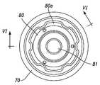
도 6은 본 발명에 의한 전자식 록장치 입력소켓의 정면도,6 is a front view of an electronic lock device input socket according to the present invention;
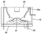
도 7은 도 6에 도시된 VI-VI선에 의한 단면도이다.FIG. 7 is a cross-sectional view taken along line VI-VI of FIG. 6.
<도면의 주요 부분에 관한 부호의 설명><Explanation of symbols on main parts of the drawings>
50 : 키 60 : 키 헤드50: key 60: key head
60a : 돌출부 61 : 이너 단자60a: protrusion 61: inner terminal
62 : 아웃터 단자 63 : PCB62: outer terminal 63: PCB
64 : 칩 70 : 입력소켓64: chip 70: input socket
본 발명은 전자식 록장치에 관한 것으로서, 특히 칩이 설치된 키의 헤드부에 일정각도마다 돌기를 형성하고 상기 키 헤드가 삽입되는 록장치의 입력소켓에 상기 돌기들이 걸릴 수 있도록 홈을 형성하여 키를 입력소켓에 꽂은 상태에서 회전시킬 수 있도록 구성된 전자식 록장치에 관한 것이다.The present invention relates to an electronic lock device, and in particular, a protrusion is formed at a predetermined angle in a head portion of a key in which a chip is installed, and a groove is formed so that the protrusions can be caught in an input socket of the lock device in which the key head is inserted. The present invention relates to an electronic lock configured to rotate while plugged into an input socket.
전자식 록장치는 칩이 설치된 키와 상기 키의 헤드와 접촉하여 칩에 입력된 전자코드를 읽어 이것이 미리 입력된 것과 동일하면 록을 해제하도록 전자적 동작을 수행하는 입력소켓으로 구성된다.The electronic lock apparatus is composed of a key in which a chip is installed and an input socket which reads an electronic code input to the chip in contact with the head of the key and performs an electronic operation to release the lock if it is the same as that previously input.
본 발명은 이러한 록장치에서 키의 헤드와 헤드가 접촉하게 되는 입력소켓에 관한 것이다.The present invention relates to an input socket in which the head of the key is in contact with the lock in such a lock device.
종래의 록장치는 도 1에 도시된 바와 같이 손으로 잡을 수 있도록 키(10)의 모양이 형성되어 있고 키(10)의 전방에는 키 헤드(20)가 설치되어 있다. 키 헤드(20)에는 전술한 바와 같이 칩이 설치되어 있고 칩에는 전자코드가 기억되어져 있다. 칩은 두 개의 단자에 연결되어 있고 두 개의 단자가 상기한 키 헤드(20)까지 연장되어 있으며, 그 키 헤드(20)는 입력소켓(30)의 홈(40)에 삽입되어 접촉된다. 이때 입력소켓(30)에 연장된 두 개의 단자에 키 헤드(20)의 두 개의 단자가 접촉하여 키 헤드(20)의 칩에 입력된 전자코드가 입력소켓(30)으로 읽히게 되고 그 정보는 입력소켓(30) 쪽의 PCB에 전달되어 그 코드가 맞는지 여부를 결정하게 된다. 물 론 그 코드가 맞으면 록을 해제하도록 동작된다.In the conventional lock apparatus, as shown in FIG. 1, the shape of a
이러한 구조의 록장치는 록을 해제하기 위해 키(10)에 돌출된 돌출부(10a)를 형성하고 그 돌출부(10a)가 록장치의 한 부분에 끼워지도록 한 다음 코드가 맞는 경우에 한하여 회전이 가능토록 하여 록을 해제하게 되는 구조를 갖는다. 따라서 이 돌출부(10a)를 키(10)에 형성해야 하기 때문에 어느 정도의 키(10)의 크기는 꼭 유지해야하고 또 돌출부(10a)가 끼워져 맞물리게 되는 부분을 입력소켓부분에 형성하여야 하기 때문에 입력소켓의 크기를 줄이는데도 문제점이 있다.The lock device of this structure forms a
본 발명은 상기한 종래 기술의 문제점을 해결하기 위하여 안출된 것으로서, 록장치의 키 헤드에 일정각도마다 돌출부를 형성하고 입력소켓에는 이에 대응하는 홈을 형성하여 키를 돌림으로써 입력소켓을 회전시킬 수 있는 구조를 갖는 소형화된 키 헤드를 갖는 전자식 록장치를 제공하는데 그 목적이 있다.The present invention has been made in order to solve the above problems of the prior art, by forming a protrusion at a predetermined angle in the key head of the locking device and by forming a groove corresponding to the input socket to rotate the input socket by turning the key. It is an object of the present invention to provide an electronic lock apparatus having a miniaturized key head having a structure in which the present invention is constructed.
본 발명에 의한 전자식 록장치는 반구형 모양으로 이너 단자가 아웃터 단자가 설치된 키 헤드를 갖는 키와, 상기 키 헤드가 삽입되어 키 헤드의 이너 단자와 아웃터 단자와 접촉하게 되는 단자들이 설치된 홈을 갖는 입력소켓을 포함하는 전자식 록장치에 있어서, 상기 키 헤드 둘레에는 돌출된 돌출부가 형성되고, 상기 입력소켓의 홈에는 상기 돌출부 각각이 삽입되어 걸리게 되는 홈들이 형성되어, 키 헤드를 입력소켓에 삽입한 상태에서 키를 회전시키면 입력소켓도 회전되도록 구성된 것을 특징으로 한다.The electronic locking device according to the present invention has a hemispherical shape and an input having a key having an inner terminal having a key head provided with an outer terminal, and a groove provided with terminals in which the key head is inserted into contact with the inner terminal and the outer terminal of the key head. An electronic lock device comprising a socket, wherein a protruding protrusion is formed around the key head, and grooves in which the protrusions are inserted and engaged are formed in grooves of the input socket so that the key head is inserted into the input socket. Rotating the key is characterized in that the input socket is also configured to rotate.
여기서, 상기 돌출부는 60도 마다 형성된 것을 특징으로 한다.Here, the protrusion is characterized in that formed every 60 degrees.
또, 상기 키 헤드는 PCB에 칩이 결합되고, 아웃터 단자와 이너 단자가 모두 연결된 상태에서 인서트 사출에 의해 제작된 것을 특징으로 한다.In addition, the key head is characterized in that the chip is coupled to the PCB, it is produced by insert injection in the state that both the outer terminal and the inner terminal is connected.
또, 상기 이너 단자는 중앙 정면으로 돌출되고, 아웃터 단자는 이너 단자와 이격되어 측면에 돌출되어 있도록 구성된 것을 특징으로 한다.In addition, the inner terminal protrudes toward the front of the center, the outer terminal is characterized in that it is configured to protrude to the side spaced apart from the inner terminal.
이하, 본 발명의 실시 예를 참조된 도면을 참조하여 설명하면 다음과 같다.Hereinafter, embodiments of the present invention will be described with reference to the accompanying drawings.
우선 참조된 도면, 도 1은 종래기술에 의한 전자식 록장치의 사시도, 도 2는 본 발명에 의한 전자식 록장치의 사시도, 도 3은 본 발명에 의한 전자식 록장치의 키의 정면도, 도 4는 도 3에 도시된 IV-IV선에 의한 단면도, 도 5는 본 발명에 의한 전자식 록장치 키 헤드의 분해 사시도, 도 6은 본 발명에 의한 전자식 록장치 입력소켓의 정면도, 도 7은 도 6에 도시된 VI-VI선에 의한 단면도이다.1 is a perspective view of an electronic lock apparatus according to the prior art, FIG. 2 is a perspective view of an electronic lock apparatus according to the present invention, FIG. 3 is a front view of a key of the electronic lock apparatus according to the present invention, and FIG. 3 is an exploded perspective view of the electronic lock device key head according to the present invention, FIG. 6 is a front view of the electronic lock device input socket according to the present invention, and FIG. It is sectional drawing by the VI-VI line shown in the figure.
본 발명에 의한 전자식 록장치는 도 2에 도시된 바와 같이 키(50) 본체의 전방에 키 헤드(60)가 설치되어 있고, 키 헤드(60)는 반구형태의 모양으로 형성되어 있다. 키 헤드(60)의 후방에는 60도마다 돌출부(60a)가 형성되어 있다. 그 돌출부(60a)는 일정한 두께를 갖도록 형성되어 있고, 그 최전방은 뾰족하게 형성되어 있다. 상기 키 헤드(60)에 접촉하게 되는 입력소켓(70)은 키 헤드(60)가 삽입되는 반구형의 홈(80)이 형성되어 있고, 그 홈(80)에 상기 돌출부(60a)들이 삽입될 수 있도록 각각 대응하는 위치에 홈(80a)이 형성되어 있다. 물론 이 홈(80a)들은 돌출부(60)보다 그 너비가 길게 형성되어 유격을 갖도록 되어 있다. 따라서 사용자는 키(50)를 손으로 잡고 입력소켓(70)의 홈(80)에 키 헤드(60)가 들어가도록 밀어 넣은 다음 돌리게 되면 돌출부(60a)가 홈(80a)에 걸리게 되기 때문에 키 헤드(60)의 회전을 따라 입력소켓(70)이 돌게 된다. 물론 키 헤드(60)의 칩에 입력된 전자코드가 맞는 경우에 한하여 회전될 수 있다.In the electronic locking device according to the present invention, as shown in FIG. 2, a
도 3은 키 헤드(60)의 정면을 바라본 도면으로서, 가운데 중앙에는 이너 단자(61)가 외부로 돌출되어 있고, 그 둘레에 절연물이 형성되어 있고, 그 절연물 주위에 아웃터 단자(62)가 설치되어 있다.FIG. 3 is a view of the front of the
도 4의 단면도에서 이러한 단자들의 연결구조를 잘 볼 수 있다. 키 헤드(60)의 중앙에 PCB(63)가 설치되어 있고 그 하부에 IC 칩(64)이 설치되어 있다. 또 이너 단자(61)는 중앙을 거쳐 PCB(63)에 연결되어 있고 아웃터 단자(62)도 주변부에 돌출된 다음 PCB(63)에 전기적으로 연결되어 있다. 따라서 각각의 이너 단자(61)와 아웃터 단자(62)가 각각 입력 소켓(70)의 이너 단자(81,83)와 아웃터 단자(82)에 제대로 접촉해야만 입력소켓(70)을 돌려 록을 해제할 수 있는 것이다.In the cross-sectional view of Figure 4 it can be seen well connected structure of these terminals. The PCB 63 is provided in the center of the
도 5의 분해 사시도를 보면 키 헤드(60)의 제작과정을 알 수 있다, PCB(63)에 이너 단자(61)가 접촉되어 결합된 상태에서 아웃터 단자(62)를 역시 PCB(63)에 연결한다. 이와 같이 조합된 어셈블리를 금형에 넣고 절연체를 이루는 물질인 플라스틱을 공급하여 인서트 사출하게 되는 것이다. 이렇게 소형의 칩(64)이 개발되어 헤드(60)에 모든 부품을 넣어 인서트 사출함으로써 키를 더욱 소형화할 수 있는 길을 열었다.5, the manufacturing process of the
도 6 및 도 7에 입력소켓(70)이 도시되어 있다. 도 6은 홈(80)의 내부가 잘 보이도록 도시한 입력소켓(70)의 정면도이다. 입력소켓(70)에 키 헤드(60)가 삽입 될 수 있도록 반구형의 큰 홈(80)이 형성되어 있고 그 홈(80)에 또 키 헤드(60)의 돌출부(60a)가 삽입되어 걸릴 수 있도록 6개의 홈(80a)이 60도마다 형성되어 있다.6 and 7 the
도 7을 참조하면, 입력소켓(70)의 홈 중앙에 이너 단자(83)에 연결된 판스프링 구조의 접촉부재(81)가 이너 단자(83)에 부착되어 있고, 이너 단자(83)는 하부로 연장되어 PCB(84)에 전기적으로 접촉된 구조를 갖는다. 아웃터 단자(82)는 판스프링의 접촉부재(81)로부터 이격되어 입력소켓(70)의 홈(80)의 측면으로 연장되어 설치되어 있으며, 물론 그 끝단은 PCB(84)에 연결되어 있다. 따라서 판스프링 구조의 이너 단자(81,83)에 키 헤드(60)가 삽입되어 접촉하게 되면 스프링의 탄성력에 의해 접촉감을 더욱 부드럽게 할 수 있다.Referring to FIG. 7, a
상기와 같이 구성된 전자식 록장치에서 키 헤드(60)를 입력소켓(70)의 홈(80)에 밀어 넣어 단자들이 접촉하게 되면 PCB(84)에서 코드를 확인하여 그 코드가 맞는 경우에 한하여 키 헤드(60)가 입력소켓(70)을 회전시킬 수 있도록 되어 있다. 물론 이때에는 키 헤드(60)의 돌출부(60a)가 입력소켓(70)의 홈(80a)에 걸려 있기 때문에 입력소켓(70)이 키 헤드(60)의 회전을 따라 회전하게 된다.In the electronic lock device configured as described above, when the terminals of the
이와 같이, 본 발명에 의한 전자식 록장치는 키 헤드에 돌출부를 형성하고 입력소켓에 상기 돌출부가 걸리는 홈을 형성하여 키 헤드를 넣어 전기적으로 록을 해제한 상태에서 키를 돌려 입력소켓을 회전시킴으로써 기구적으로도 록이 해제되도록 구성할 수 있는 효과를 제공한다.As described above, the electronic lock apparatus according to the present invention forms a protrusion in the key head, and a groove in which the protrusion is engaged in the input socket, and rotates the input socket by turning the key while the key head is inserted to release the lock. It also provides an effect that can be configured to unlock.
또, 키 헤드가 아닌 키 자체에 큰 돌출부를 형성하지 않아도 되기 때문에 키 의 모양을 디자인하기 유리할 뿐만 아니라 크기를 작게 할 수 있는 효과를 제공한다.In addition, since it is not necessary to form a large protrusion on the key itself rather than the key head, it is advantageous not only to design the shape of the key but also to reduce the size.
또, 본 발명에 의한 전자식 록장치는 키 헤드에 PCB와 칩이 모두 삽입된 상태에서 인서트 사출되어 제작되기 때문에 키를 소형화할 수 있는 효과를 제공한다.In addition, since the electronic lock device according to the present invention is manufactured by insert injection molding in a state in which both the PCB and the chip are inserted into the key head, the key provides a miniaturization of the key.
본 발명은 상기 실시 예에 한정되지 않고 본 발명의 기술적 요지를 벗어나지 않는 범위 내에서 당해 기술분야의 통상의 지식을 가진 자에 의해 다양하게 변형 실시될 수 있다.The present invention is not limited to the above embodiments and may be variously modified and implemented by those skilled in the art without departing from the technical gist of the present invention.
Claims (4)
Translated fromKoreanPriority Applications (6)
| Application Number | Priority Date | Filing Date | Title |
|---|---|---|---|
| KR1020050024458AKR20060102637A (en) | 2005-03-24 | 2005-03-24 | Electronic lock |
| EP06716503AEP1861570A4 (en) | 2005-03-24 | 2006-03-23 | Electrical lock apparatus |
| US11/909,443US20090235703A1 (en) | 2005-03-24 | 2006-03-23 | Electrical lock apparatus |
| JP2008502911AJP2008538394A (en) | 2005-03-24 | 2006-03-23 | Electronic locking device |
| CNA2006800095768ACN101146974A (en) | 2005-03-24 | 2006-03-23 | Electronic lock device |
| PCT/KR2006/001054WO2006112615A1 (en) | 2005-03-24 | 2006-03-23 | Electrical lock apparatus |
Applications Claiming Priority (1)
| Application Number | Priority Date | Filing Date | Title |
|---|---|---|---|
| KR1020050024458AKR20060102637A (en) | 2005-03-24 | 2005-03-24 | Electronic lock |
Publications (1)
| Publication Number | Publication Date |
|---|---|
| KR20060102637Atrue KR20060102637A (en) | 2006-09-28 |
Family
ID=37115303
Family Applications (1)
| Application Number | Title | Priority Date | Filing Date |
|---|---|---|---|
| KR1020050024458AWithdrawnKR20060102637A (en) | 2005-03-24 | 2005-03-24 | Electronic lock |
Country Status (6)
| Country | Link |
|---|---|
| US (1) | US20090235703A1 (en) |
| EP (1) | EP1861570A4 (en) |
| JP (1) | JP2008538394A (en) |
| KR (1) | KR20060102637A (en) |
| CN (1) | CN101146974A (en) |
| WO (1) | WO2006112615A1 (en) |
Family Cites Families (16)
| Publication number | Priority date | Publication date | Assignee | Title |
|---|---|---|---|---|
| US4326125A (en)* | 1980-06-26 | 1982-04-20 | Datakey, Inc. | Microelectronic memory key with receptacle and systems therefor |
| US5819563A (en)* | 1991-10-21 | 1998-10-13 | Bianco; James S. | Intelligent lock system |
| US5281945A (en)* | 1992-02-21 | 1994-01-25 | Magicorp, Inc. | Control apparatus particularly adapted for handicapped persons |
| US5322992A (en)* | 1992-06-22 | 1994-06-21 | Lynx Systems, Inc. | Implement for controlling an electronic lock mechanism |
| US5437174A (en)* | 1992-11-17 | 1995-08-01 | David Sokol | Retrofittable electronic and mechanical door lock system |
| US5385039A (en)* | 1993-01-21 | 1995-01-31 | Steelcase Inc. | Electronic lock |
| US5749253A (en)* | 1994-03-30 | 1998-05-12 | Dallas Semiconductor Corporation | Electrical/mechanical access control systems and methods |
| US5848541A (en)* | 1994-03-30 | 1998-12-15 | Dallas Semiconductor Corporation | Electrical/mechanical access control systems |
| US5473236A (en)* | 1994-07-14 | 1995-12-05 | Harrow Products, Inc. | Electronic lock system for door latch assembly |
| US5689985A (en)* | 1995-09-29 | 1997-11-25 | Schlage Lock Company | Electronic touch key providing a tactile pressure signal for an electronic lock |
| US5923264A (en)* | 1995-12-22 | 1999-07-13 | Harrow Products, Inc. | Multiple access electronic lock system |
| DE19644308C2 (en)* | 1996-10-24 | 1998-11-12 | Keso Gmbh | Flat key |
| DE19839347C1 (en)* | 1998-08-28 | 1999-12-02 | Daimler Chrysler Ag | Ignition lock system for motor vehicle developed to enable reliable detection of manipulation of the system |
| US6386007B1 (en)* | 1999-06-14 | 2002-05-14 | Siemens Automotive Corporation | Key fob with valet and car locator feature |
| US6474122B2 (en)* | 2000-01-25 | 2002-11-05 | Videx, Inc. | Electronic locking system |
| US8256254B2 (en)* | 2007-12-27 | 2012-09-04 | Utc Fire & Security Americas Corporation, Inc. | Lock portion with solid-state actuator |
- 2005
- 2005-03-24KRKR1020050024458Apatent/KR20060102637A/ennot_activeWithdrawn
- 2006
- 2006-03-23WOPCT/KR2006/001054patent/WO2006112615A1/enactiveApplication Filing
- 2006-03-23JPJP2008502911Apatent/JP2008538394A/enactivePending
- 2006-03-23EPEP06716503Apatent/EP1861570A4/ennot_activeWithdrawn
- 2006-03-23CNCNA2006800095768Apatent/CN101146974A/enactivePending
- 2006-03-23USUS11/909,443patent/US20090235703A1/ennot_activeAbandoned
Also Published As
| Publication number | Publication date |
|---|---|
| CN101146974A (en) | 2008-03-19 |
| JP2008538394A (en) | 2008-10-23 |
| WO2006112615A1 (en) | 2006-10-26 |
| EP1861570A4 (en) | 2010-07-21 |
| US20090235703A1 (en) | 2009-09-24 |
| EP1861570A1 (en) | 2007-12-05 |
Similar Documents
| Publication | Publication Date | Title |
|---|---|---|
| US8961207B2 (en) | Card connector | |
| US7095617B1 (en) | Portable computer peripheral apparatus with reinforced connecting ring | |
| JP5148479B2 (en) | Electromechanical locking device | |
| US7578689B2 (en) | Card edge connector with latch | |
| US7341467B2 (en) | Card edge connector with ejecting means | |
| US7435113B2 (en) | Electric connector | |
| JP3109992U (en) | Outlet with safety mechanism | |
| CN111033915B (en) | Locking device for plug connection | |
| US7500876B2 (en) | Shielded Receptacle Connector | |
| TW201725814A (en) | Rotary socket | |
| US10707457B2 (en) | Battery case and robot having the same | |
| US20180212362A1 (en) | Card edge connector having metallic member formed integrally with insulative housing | |
| US20170110816A1 (en) | Clip and electrical connector assembly | |
| JP2005340077A (en) | Card connector | |
| SG187293A1 (en) | Card connector | |
| KR20060102637A (en) | Electronic lock | |
| US6527577B1 (en) | CPU socket having separate retention member | |
| US6508659B1 (en) | Electrical socket having a backup means | |
| JP2004220787A (en) | Connector for card | |
| JP2008108467A (en) | Lever type mating connector | |
| KR101255214B1 (en) | Electronic device comprising battery opening/closing structure | |
| KR100755816B1 (en) | Structure for mounting antenna | |
| JP4355666B2 (en) | connector | |
| JP4527887B2 (en) | Card connector erroneous insertion prevention device | |
| KR101638179B1 (en) | Flexible Cable Connector System with Double Combining Structure |
Legal Events
| Date | Code | Title | Description |
|---|---|---|---|
| PA0109 | Patent application | Patent event code:PA01091R01D Comment text:Patent Application Patent event date:20050324 | |
| PG1501 | Laying open of application | ||
| N231 | Notification of change of applicant | ||
| PN2301 | Change of applicant | Patent event date:20081124 Comment text:Notification of Change of Applicant Patent event code:PN23011R01D | |
| PC1203 | Withdrawal of no request for examination | ||
| WITN | Application deemed withdrawn, e.g. because no request for examination was filed or no examination fee was paid |