KR20060101821A - Electrical contact sensor and human interface device using the same - Google Patents
Electrical contact sensor and human interface device using the sameDownload PDFInfo
- Publication number
- KR20060101821A KR20060101821AKR1020050023382AKR20050023382AKR20060101821AKR 20060101821 AKR20060101821 AKR 20060101821AKR 1020050023382 AKR1020050023382 AKR 1020050023382AKR 20050023382 AKR20050023382 AKR 20050023382AKR 20060101821 AKR20060101821 AKR 20060101821A
- Authority
- KR
- South Korea
- Prior art keywords
- contact
- signal
- generating
- signal generator
- reference signal
- Prior art date
- Legal status (The legal status is an assumption and is not a legal conclusion. Google has not performed a legal analysis and makes no representation as to the accuracy of the status listed.)
- Granted
Links
Images


Classifications
- G—PHYSICS
- G06—COMPUTING OR CALCULATING; COUNTING
- G06F—ELECTRIC DIGITAL DATA PROCESSING
- G06F3/00—Input arrangements for transferring data to be processed into a form capable of being handled by the computer; Output arrangements for transferring data from processing unit to output unit, e.g. interface arrangements
- G06F3/01—Input arrangements or combined input and output arrangements for interaction between user and computer
- G06F3/03—Arrangements for converting the position or the displacement of a member into a coded form
- G06F3/033—Pointing devices displaced or positioned by the user, e.g. mice, trackballs, pens or joysticks; Accessories therefor
- G06F3/0354—Pointing devices displaced or positioned by the user, e.g. mice, trackballs, pens or joysticks; Accessories therefor with detection of 2D relative movements between the device, or an operating part thereof, and a plane or surface, e.g. 2D mice, trackballs, pens or pucks
- G06F3/03543—Mice or pucks
- G—PHYSICS
- G06—COMPUTING OR CALCULATING; COUNTING
- G06F—ELECTRIC DIGITAL DATA PROCESSING
- G06F3/00—Input arrangements for transferring data to be processed into a form capable of being handled by the computer; Output arrangements for transferring data from processing unit to output unit, e.g. interface arrangements
- G06F3/01—Input arrangements or combined input and output arrangements for interaction between user and computer
- G06F3/03—Arrangements for converting the position or the displacement of a member into a coded form
- G06F3/033—Pointing devices displaced or positioned by the user, e.g. mice, trackballs, pens or joysticks; Accessories therefor
- G06F3/0354—Pointing devices displaced or positioned by the user, e.g. mice, trackballs, pens or joysticks; Accessories therefor with detection of 2D relative movements between the device, or an operating part thereof, and a plane or surface, e.g. 2D mice, trackballs, pens or pucks
- G06F3/03547—Touch pads, in which fingers can move on a surface
- G—PHYSICS
- G06—COMPUTING OR CALCULATING; COUNTING
- G06F—ELECTRIC DIGITAL DATA PROCESSING
- G06F3/00—Input arrangements for transferring data to be processed into a form capable of being handled by the computer; Output arrangements for transferring data from processing unit to output unit, e.g. interface arrangements
- G06F3/01—Input arrangements or combined input and output arrangements for interaction between user and computer
- G06F3/03—Arrangements for converting the position or the displacement of a member into a coded form
- G06F3/033—Pointing devices displaced or positioned by the user, e.g. mice, trackballs, pens or joysticks; Accessories therefor
- G06F3/038—Control and interface arrangements therefor, e.g. drivers or device-embedded control circuitry
- G06F3/0383—Signal control means within the pointing device
- G—PHYSICS
- G06—COMPUTING OR CALCULATING; COUNTING
- G06F—ELECTRIC DIGITAL DATA PROCESSING
- G06F2203/00—Indexing scheme relating to G06F3/00 - G06F3/048
- G06F2203/033—Indexing scheme relating to G06F3/033
- G06F2203/0339—Touch strips, e.g. orthogonal touch strips to control cursor movement or scrolling; single touch strip to adjust parameter or to implement a row of soft keys
Landscapes
- Engineering & Computer Science (AREA)
- General Engineering & Computer Science (AREA)
- Theoretical Computer Science (AREA)
- Human Computer Interaction (AREA)
- Physics & Mathematics (AREA)
- General Physics & Mathematics (AREA)
- Electronic Switches (AREA)
- Measurement Of Length, Angles, Or The Like Using Electric Or Magnetic Means (AREA)
Abstract
Translated fromKoreanDescription
Translated fromKorean도 1a는 종래의 기술에 따른 전기적 접촉센서의 회로도를 도시한 도면.Is a circuit diagram of an electrical contact sensor according to the prior art;
도 1b는 도 1a의 전기적 접촉센서에 있어서, 접촉 물체가 접촉하지 않았을 경우의 동작 회로도.FIG. 1B is an operation circuit diagram when the contact object is not in contact with the electrical contact sensor of FIG.
도 1c는 도 1a의 전기적 접촉센서에 있어서, 접촉 물체가 접촉한 경우의 동작 회로도.1C is an operation circuit diagram when a contact object is touched in the electrical contact sensor of FIG. 1A;
도 2는 도 1a의 전기적 접촉센서에 있어서, 접촉 물체가 접촉된 경우와 접촉되지 않은 경우의 전기적 접촉센서의 출력 레벨 변화를 도시한 도면.2 is a view showing a change in the output level of the electrical contact sensor in the electrical contact sensor of FIG.
도 3은 본 발명의 기술에 따른 전기적 접촉센서의 블록도3 is a block diagram of an electrical contact sensor in accordance with the techniques of the present invention.
도 4는 본 발명의 기술에 따른 전기적 접촉센서의 회로도를 도시한 도면.4 shows a circuit diagram of an electrical contact sensor in accordance with the teachings of the present invention.
도 5a는 도 4의 전기적 접촉센서에 있어서, 접촉 물체가 접촉하지 않았을 경우의 동작 회로도.FIG. 5A is an operation circuit diagram when the contact object is not in contact with the electrical contact sensor of FIG. 4. FIG.
도 5b는 도 4의 전기적 접촉센서에 있어서, 접촉 물체가 접촉하지 않은 경우의 신호 파형도를 도시한 도면.FIG. 5B is a diagram illustrating signal waveforms when the contact object is not in contact with the electrical contact sensor of FIG. 4; FIG.
도 5c는 도 4의 전기적 접촉센서에 있어서, 접촉 물체가 접촉한 경우의 동작 회로도.FIG. 5C is an operation circuit diagram when a contact object contacts the electrical contact sensor of FIG. 4. FIG.
도 5d는 도 4의 전기적 접촉센서에 있어서, 접촉 물체가 접촉한 경우의 신호 파형도를 도시한 도면.FIG. 5D illustrates a signal waveform diagram when a contact object contacts the electrical contact sensor of FIG. 4. FIG.
도 6은 본 발명의 전기적 접촉센서를 이용하는 마우스의 제 1 실시예를 도시한 도면.Figure 6 shows a first embodiment of a mouse using the electrical contact sensor of the present invention.
도 7은 도 6의 마우스의 동작 전원 제어 방법을 도시한 도면.7 is a diagram illustrating a method of controlling operation power of the mouse of FIG. 6.
도 8a은 본 발명의 전기적 접촉센서를 이용하는 마우스의 제 2 실시예를 도시한 도면.Fig. 8A shows a second embodiment of a mouse using the electrical contact sensor of the present invention.
도 8b은 도 8a의 전기적 접촉센서에 연결되는 접촉 패드들의 배치구조를 도시한 도면.FIG. 8B illustrates an arrangement of contact pads connected to the electrical contact sensor of FIG. 8A. FIG.
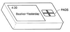
도 9a는 본 발명의 전기적 접촉센서를 이용하는 휴대 장치의 제 1 실시예를 도시한 도면.Fig. 9A shows a first embodiment of a portable device using the electrical contact sensor of the present invention.
도 9b는 본 발명의 전기적 접촉센서를 이용하는 휴대 장치의 제 2 실시예를 도시한 도면.Fig. 9B shows a second embodiment of a portable device using the electrical contact sensor of the present invention.
본 발명은 접촉센서에 관한 것으로, 특히 접촉 물체의 접촉 유무를 전기적으로 감지하여 통보하는 전기적 접촉센서 및 이를 이용하는 휴먼 인터페이스 장치에 관한 것이다.BACKGROUND OF THE
일반적으로 접촉센서는 크게 기구적 방법으로 동작하는 푸시버튼과 비기구적 방법으로 동작하는 전기적 접촉센서로 나뉜다.In general, the touch sensor is divided into a push button operating in a mechanical manner and an electrical contact sensor operating in a non-mechanical manner.
푸시버튼은 제품의 생산 비용이 저렴한 반면에 접촉 물체의 선택을 감지하기 위한 기구적 접점과 버튼의 복원력을 위한 스프링 장치를 필요로 하게 되어, 제품의 소형화가 어려울 뿐만 아니라 구조도 복잡한 단점이 있으며, 전기적 접촉센서는 제품의 생산 비용은 푸시 버튼에 비해 많이 소요되나 소형화에 더 유리한 장점을 제공한다.While the pushbuttons are inexpensive to produce, they require mechanical contacts to detect the selection of contact objects and spring devices for the resiliency of the buttons. Electrical contact sensors offer higher production costs than pushbuttons, but offer advantages over miniaturization.
본 발명에서 특히 관심을 가지는 분야는 전기적 접촉센서에 관한 것이다.Of particular interest in the present invention relates to electrical contact sensors.
도 1a 내지 도 1c는 종래의 기술에 따른 전기적 접촉센서의 회로도를 도시한 도면이다.1A to 1C are circuit diagrams of an electrical contact sensor according to the related art.
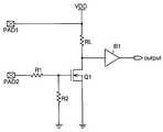
도 1a는 전기적 접촉센서의 기본 회로도이고, 도 1b는 접촉 물체가 접촉하지 않았을 경우의 전기적 접촉센서의 동작 회로도이고, 도 1c는 접촉 물체가 접촉한 경우의 전기적 접촉센서의 동작 회로도이다.FIG. 1A is a basic circuit diagram of an electrical contact sensor, FIG. 1B is an operation circuit diagram of the electrical contact sensor when the contact object is not in contact, and FIG. 1C is an operation circuit diagram of the electrical contact sensor when the contact object is in contact.
계속하여 도 1a를 참조하면, 전기적 접촉센서는 접촉 물체가 접촉되는 두개의 접촉 패드들(또는 접촉 핀들)(PAD1, PAD2)과, 접촉물체로부터 전달되는 정전기로부터 내부 회로를 보호하기 위한 제 1 저항(R1)과, 능동 소자 N형 FET(Q1)와, N형 FET(Q1)의 바이어스 전압 설정을 위한 제 2 저항(R2)과, N형 FET(Q1)의 부하(load)가 되는 제 3 저항(RL)과, N형 FET(Q1)의 출력 전압을 버퍼하는 출력 버퍼(B1)를 구비한다.With continued reference to FIG. 1A, the electrical contact sensor includes two contact pads (or contact pins) PAD1 and PAD2 with which a contact object is contacted, and a first resistor for protecting the internal circuit from static electricity transmitted from the contact object. (R1), the active element N-type FET Q1, the second resistor R2 for setting the bias voltage of the N-type FET Q1, and the third to be a load of the N-type FET Q1. A resistor RL and an output buffer B1 for buffering the output voltage of the N-type FET Q1 are provided.
이와 같은 전기적 접촉센서에 접촉 물체가 접촉하지 않으면, 도 1b의 회로도와 같이, 접촉 패드들(PAD1, PAD2)은 개방상태가 되며, 이에 따라 N형 FET(Q1)의 게이트는 제 2 저항(R2)을 통해 접지전압과 연결된다.If a contact object does not contact such an electrical contact sensor, as shown in the circuit diagram of FIG. 1B, the contact pads PAD1 and PAD2 are opened, so that the gate of the N-type FET Q1 is connected to the second resistor R2. Is connected to ground voltage.
접지 전압과 게이트가 연결된 N형 FET(Q1)는 오프가 되고, N형 FET(Q1) 및 제 3 저항(RL)을 통한 전류의 흐름은 없게 된다. 이에 N형 FET(Q1)의 드레인에는 전원 전압(VDD)이 인가되고, 출력 버퍼(B1)는 N형 FET(Q1)의 드레인에 인가된 전원 전압(VDD)을 입력 받아 "H" 신호를 발생하여 출력한다.The N-type FET Q1 connected with the ground voltage and the gate is turned off, and there is no flow of current through the N-type FET Q1 and the third resistor RL. The power supply voltage VDD is applied to the drain of the N-type FET Q1, and the output buffer B1 receives the power supply voltage VDD applied to the drain of the N-type FET Q1 to generate a "H" signal. To print.
반면에 전기적 접촉센서에 접촉 물체가 접촉하게 되면, 전기적 접촉센서는 도 1c의 동작 회로도를 가지게 된다.On the other hand, when the contact object is in contact with the electrical contact sensor, the electrical contact sensor has the operation circuit diagram of Figure 1c.
이때의 접촉 물체는 일반적으로 전도성이 있는 저항체인 사람의 손가락이 된다.The contact object at this time becomes a human finger which is generally a conductive resistor.
계속하여 도 1c를 참조하면, 두개의 접촉 패드들(PAD1, PAD2)은 저항체(RH)를 통해 연결되며, 저항체(RH)를 통해서 전원 전압(VDD)과 접지 전압(VGND)의 전압차에 의해 발생된 전류가 흐르게 된다. 이하에서는 접촉 패드에 접속된 사람의 저항체(RH)를 제 4 저항(RH)으로 칭하기로 한다.Referring to FIG. 1C, two contact pads PAD1 and PAD2 are connected through a resistor RH and are connected by a voltage difference between the power supply voltage VDD and the ground voltage VGND through the resistor RH. The generated current flows. Hereinafter, the resistor RH of a person connected to the contact pad will be referred to as a fourth resistor RH.
그러면 N형 FET(Q1)의 게이트에는 "전원 전압(VDD) × 제 2 저항(R2)/(제 1 저항(R1) + 제 4 저항(RH))"의 전압이 인가되게 된다.Then, a voltage of "power supply voltage VDD x second resistor R2 / (first resistor R1 + fourth resistor RH)" is applied to the gate of the N-type FET Q1.
그리고 N형 FET(Q1)의 게이트에 인가되는 전압이 N형 FET(Q1)의 문턱 전압(Threshold Voltage ; 이하 Vth)보다 크게 되면, N형 FET(Q1)는 온이 되어 N형 FET(Q1)와 제 3 저항(RL)을 통해서 "A × (VG - Vth)2"의 드레인 전류(IL)가 흐르게 된다. 이때 A는 각 FET의 고유 상수값이고, Vth는 각 FET의 문턱 전압값이다.When the voltage applied to the gate of the N-type FET Q1 is greater than the threshold voltage (Vth) of the N-type FET Q1, the N-type FET Q1 is turned on and the N-type FET Q1 is turned on. The drain current IL of "A x (VG-Vth) 2" flows through the third resistor RL. Where A is the intrinsic constant value of each FET and Vth is the threshold voltage value of each FET.
즉, N형 FET(Q1)의 드레인에는 "전원 전압(VDD) - 드레인 전류(IL) × 제 3 저항(RL)"의 전압(VD)이 인가되게 된다.That is, the voltage VD of "power supply voltage VDD-drain current IL x third resistor RL" is applied to the drain of the N-type FET Q1.
특히, N형 FET(Q1)의 게이트에 "드레인 전류(IL) × 제 3 저항(RL) > 전원 전압(VDD)"으로 계산되는 드레인 전류(IL)를 흐르게 하는 전압이 인가되면, N형 FET(Q1)의 드레인 전압은 "0"이 된다.In particular, when a voltage is applied to the gate of the N-type FET Q1, a drain current IL, which is calculated as "drain current IL x third resistor RL> power supply voltage VDD," is applied. The drain voltage of (Q1) becomes "0".
이상에서 살펴본 바와 같이 두개의 접촉 패드들(PAD1, PAD2)에 충분히 작은 저항값을 가지는 접촉 물체가 접촉하게 되면, N형 FET(Q1)의 드레인에는 "0"에 근접한 값을 가지는 드레인 전압이 발생하게 되고, 드레인 전압은 출력 버퍼(B1)를 거쳐서 "L" 신호로 출력된다.As described above, when two contact pads PAD1 and PAD2 come into contact with a sufficiently small resistance value, a drain voltage having a value close to "0" is generated in the drain of the N-type FET Q1. The drain voltage is output as an "L" signal via the output buffer B1.
이와 같이 종래의 전기적 접촉센서는 두개의 접촉 패드를 구비하고, 전도성 이 있는 접촉 물체가 동시에 두 접촉 패드에 접촉되면 이를 전기적으로 감지하고, 이에 따른 신호를 발생하여 출력하여 주었다.As described above, the conventional electrical contact sensor includes two contact pads, and when a conductive contact object contacts the two contact pads at the same time, it electrically detects and generates and outputs a signal accordingly.
종래의 전기적 접촉센서는 기구적 구성없이 순수하게 전기적 접촉으로만 접촉 사실을 전기적 신호로 변환하여 각종 전기 전자 기기에 응용할 수 있도록 하였으나, 접촉 물체의 접촉을 감지하기 위해서는 반드시 두개의 접촉 패드를 필요로 하였다.Conventional electrical contact sensors can be applied to various electrical and electronic devices by converting the contact facts into electrical signals with pure electrical contact without any mechanical configuration, but two contact pads are required to detect the contact of the contact object. It was.
이에 종래의 전기적 접촉센서는 두개의 접촉 패드를 반드시 구비해야 함에 따라 소형화의 한계가 있었다.Accordingly, the conventional electrical contact sensor has to be provided with two contact pads, so there is a limit of miniaturization.
또한 종래의 전기적 접촉센서는 인간의 신체에서 발생하는 저항 성분을 이용하여 접촉 여부를 감지하므로, 두개의 접촉 패드에 접촉되는 접촉 물체도 반드시 일정한 저항 성분을 을 가진 물체여야 하는 제약을 가진다.In addition, the conventional electrical contact sensor detects the contact by using a resistance component generated in the human body, and therefore, a contact object contacting two contact pads must be an object having a constant resistance component.
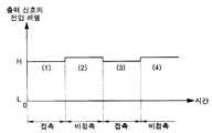
이에 사람의 손가락이 전기적 접촉 패드에 접촉되었으나, 사람이 비전도성을 가지는 장갑을 끼거나, 맨손이라 할지라도 손의 표면이 건조하여 충분한 전도성을 가지게 못하게 되면, 전기적 접촉센서는 도 2에 도시된 바와 같은 출력신호를 발생하게 된다.When a person's finger is in contact with the electrical contact pad, but the person wears a non-conductive glove or the bare surface is dry and does not have sufficient conductivity, the electrical contact sensor is shown in FIG. 2. The same output signal is generated.
즉, 접촉 패드들(PAD1, PAD2)에 접촉 물체가 접촉되었음(구간 (1), 구간 (3))에도 불구하고 접촉 물체가 충분한 전도성을 가지지 못하게 되면, 접촉 패드들(PAD1, PAD2)에는 매우 높은 저항값을 가지는 저항이 연결되는 것과 같은 상태가 된다. 이에 N형 FET(Q1)에는 미소한 전류만이 인가되어 전기적 접촉센서는 "H" 신호를 발생하게 된다.That is, when the contact object does not have sufficient conductivity despite the contact object contacting the contact pads PAD1 and PAD2 (
이와 같이 종래의 전기적 접촉센서의 경우, 접촉 물체가 접촉되었음에도 불구하고, 접촉 물체가 충분한 전도성을 가지게 못하게 되면, 전기적 접촉센서는 이를 감지하지 못하여 오동작되는 경우가 있었다.As described above, in the case of the conventional electrical contact sensor, even though the contact object is in contact, when the contact object does not have sufficient conductivity, the electrical contact sensor may not detect this and malfunction.
본 발명의 목적은 전도성이 충분하지 않은 접촉 물체가 접촉되어도 접촉을 감지할 수 있도록 하는 전기적 접촉센서를 제공하는 것이다.SUMMARY OF THE INVENTION An object of the present invention is to provide an electrical contact sensor that can detect a contact even when a contact object having insufficient conductivity is touched.
본 발명의 다른 목적은 하나의 접촉 패드만으로도 접촉 물체의 접촉 유무를 감지할 수 있도록 하는 전기적 접촉센서를 제공하는 것이다.Another object of the present invention is to provide an electrical contact sensor capable of detecting the presence or absence of contact of a contact object with only one contact pad.
본 발명의 또 다른 목적은 전기적 접촉센서를 이용하는 휴먼 인터페이스 장치를 제공하는 것이다.Still another object of the present invention is to provide a human interface device using an electrical contact sensor.
상기 목적 및 다른 목적을 달성하기 위한 본 발명의 전기적 접촉센서는 기준 신호를 생성하는 기준 신호 발생부와, 상기 기준 신호를 지연하여 제 1 신호를 발생하는 제 1 신호 발생부와, 접촉 패드를 구비하고, 상기 접촉 패드의 접촉시에는 상기 기준 신호를 상기 제 1 신호보다 더 많이 지연하고, 비접촉시에는 상기 기준 신호를 상기 제 1 신호보다 작게 지연하여 제 2 신호를 발생하는 제 2 신호 발생부와, 상기 제 1 신호에 동기되어 상기 제 2 신호를 수신하여 접촉 신호를 발생하는 접촉 신호 발생부를 구비하는 것을 특징으로 한다.The electrical contact sensor of the present invention for achieving the above and other objects has a reference signal generator for generating a reference signal, a first signal generator for delaying the reference signal to generate a first signal, and a contact pad And a second signal generator for delaying the reference signal more than the first signal when the contact pad is in contact, and generating the second signal by delaying the reference signal smaller than the first signal when not in contact. And a contact signal generator for receiving the second signal in synchronization with the first signal and generating a contact signal.
상기 또 다른 목적을 달성하기 위한 본 발명의 제 1 형태에 따른 휴먼 인터페이스 장치는 접촉 패드를 구비하고, 상기 접촉 패드의 접촉 여부에 따라 접촉 신호를 각각 발생하는 적어도 하나 이상의 전기적 접촉 센서와, 상기 접촉 신호에 응답하여 전력 제어 동작을 수행하는 제어부를 구비하고, 상기 전기적 접촉 센서는 기준 신호를 생성하는 기준 신호 발생부와, 상기 기준 신호를 지연하여 제 1 신호를 발생하는 제 1 신호 발생부와, 상기 접촉 패드를 구비하고, 상기 접촉 패드의 접촉시에는 상기 기준 신호를 상기 제 1 신호보다 더 많이 지연하고, 비접촉시에는 상기 기준 신호를 상기 제 1 신호보다 작게 지연하여 제 2 신호를 발생하는 제 2 신호 발생부와, 상기 제 1 신호에 동기되어 상기 제 2 신호를 수신하여 상기 접촉 신호를 발생하는 접촉 신호 발생부를 구비하는 것을 특징으로 한다.According to another aspect of the present invention, there is provided a human interface device including a contact pad, at least one electrical contact sensor for generating a contact signal according to whether the contact pad is in contact, and the contact. And a control unit configured to perform a power control operation in response to a signal, wherein the electrical contact sensor comprises: a reference signal generator for generating a reference signal, a first signal generator for delaying the reference signal and generating a first signal; And a contact pad having the contact pad and delaying the reference signal more than the first signal when the contact pad is in contact, and generating the second signal by delaying the reference signal smaller than the first signal when not in contact. A second signal generator and a touch signal generator for receiving the second signal in synchronization with the first signal to generate the contact signal; Characterized by comprising a.
상기 또 다른 목적을 달성하기 위한 본 발명의 제 2 형태에 따른 휴먼 인터페이스 장치는 데이터를 화면에 디스플레이하는 디스플레이부와 소정의 패턴으로 배치된 복수개의 접촉 패드들을 구비하고, 접촉 물체가 상기 복수개의 접촉 패드들 중 적어도 하나 이상의 접촉 패드에 접촉됨에 따라 적어도 하나 이상의 접촉 신호 들을 발생하는 전기적 스크롤 장치와, 상기 접촉 신호들을 분석하여 상기 접촉 물체가 접촉된 상기 접촉 패드들의 위치를 파악하고, 상기 접촉 패드들의 위치에 대응되는 방향으로 상기 화면을 스크롤 하는 제어부를 구비하고, 상기 전기적 스크롤 장치는 상기 접촉 패드를 구비하고, 상기 접촉 패드에 상기 접촉 물체가 접촉됨에 따라 상기 접촉 신호를 각각 발생하는 복수개의 전기적 접촉 센서들을 구비하는 것을 특징으로 한다.According to a second aspect of the present invention, there is provided a human interface device including a display unit for displaying data on a screen, and a plurality of contact pads arranged in a predetermined pattern, and a contact object contacts the plurality of contacts. An electrical scroll device that generates at least one or more touch signals upon contact with at least one of the pads, and analyzes the touch signals to determine the location of the contact pads that the contact object contacts, And a control unit for scrolling the screen in a direction corresponding to a position, wherein the electric scroll device includes the contact pad, and a plurality of electrical contacts respectively generating the contact signal as the contact object contacts the contact pad. And sensors.
이하, 첨부한 도면을 참고로 하면 본 발명의 전기적 접촉센서 및 이를 이용하는 휴먼 인터페이스 장치를 설명하면 다음과 같다.Hereinafter, referring to the accompanying drawings, an electrical contact sensor and a human interface device using the same will be described.
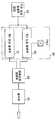
도 3은 본 발명의 기술에 따른 전기적 접촉센서의 블럭도를 도시한 도면이다.3 is a block diagram of an electrical contact sensor in accordance with the teachings of the present invention.
도면에 도시된 바와 같이, 본 발명의 전기적 접촉센서는 기준 신호 발생부(10)와, 제 1 신호 발생부(21)와, 제 2 신호 발생부(22)와, 접촉 신호 발생부(30)와, 필터부(40)를 구비한다.As shown in the figure, the electrical contact sensor of the present invention, the
이하 각 구성요소의 기능을 살펴보면 다음과 같다.Looking at the function of each component as follows.
기준 신호 발생부(10)는 AC(Alternate Current) 신호 또는 클럭 신호를 기준 신호(ref_sig)로서 발생하여 제 1 신호 발생부(21)와 제 2 신호 발생부(22)에 각각 인가한다.The
제 1 신호 발생부(21)는 접촉 물체의 접촉 여부에 상관없이 항상 기준 신호(ref_sig)를 항상 제 1 시간 지연하여 제 1 신호(sig1)를 발생한다.The
제 2 신호 발생부(22)는 접촉 물체가 접촉되는 접촉 패드(PAD)를 구비하고, 접촉 패드(PAD)에 접촉 물체가 접촉되지 않으면 기준 신호(ref_sig)를 지연하지 않고, 접촉 패드(PAD)에 접촉 물체가 접촉되면 기준 신호(ref_sig)를 제 1 시간 보다 더 많이 지연하여 제 2 신호(sig2)를 발생한다.The
즉, 제 2 신호 발생부(22)는 접촉 물체의 비접촉시에는 제 1 신호(sig1)의 위상보다 빠른 위상을 가지는 제 2 신호(sig2)를 생성하고, 접촉시에는 제 1 신호(sig1)의 위상보다 느린 위상을 가지는 제 2 신호(sig2)를 생성한다.That is, the
본 발명에서의 접촉 물체는 소정의 정전 용량을 가지는 모든 물체가 적용될 수 있으며, 대표적인 예로 많은 량의 전하를 축적할 수 있는 사람의 인체가 있다.In the present invention, any object having a predetermined capacitance may be applied to the contact object, and a representative example is a human body capable of accumulating a large amount of electric charge.
접촉 신호 발생부(30)는 제 1 신호(sig1)에 동기되어 제 2 신호(sig2)를 샘플링 및 래치하여 접촉 신호(con_sig)를 발생한다.The
그리고 필터부(40)는 접촉 신호(con_sig)를 수신하고, 접촉 신호 발생부(30)의 접촉 물체가 접촉 패드에 접촉하는 순간 또는 접촉 물체의 불안정하게 접촉하는 순간에 발생하는 각종 노이즈 신호를 제거하고, 안정화 및 평활화하여 출력 신호(out_sig)를 발생한다.The
도 4는 도 3의 전기적 접촉센서의 일실시예에 따른 회로도로, 도면을 참조하면, 제 1 신호 발생부(21)는 기준 신호 발생부(10)와 접촉 신호 발생부(30) 사이에 위치하는 제 1 저항(R11)과, 제 1 저항(R11)과 접촉 신호 발생부(30)의 사이에 위치하며 접지 전압(VSS)과 연결되는 캐패시터(CAP)를 포함하고, 제 2 신호 발생부(22)는 기준 신호 발생부(10)와 접촉 신호 발생부(30) 사이에 위치하는 제 2 저항 (R12)과, 제 2 저항(R12)과 접촉 신호 발생부(30)의 사이에 위치하여 정전용량을 가지는 접촉물체가 접촉되도록 하는 접촉 패드(PAD)를 포함한다.4 is a circuit diagram according to an embodiment of the electrical contact sensor of FIG. 3. Referring to the drawings, the
이때 제 1 및 제 2 저항(R11, R12)은 기준 신호 발생부(10)와 캐패시터(CAP)간의 지연 성분과 기준 신호 발생부(10)와 접촉 패드(PAD)간의 지연 성분을 동일하도록 하는 저항으로, 극히 미약한 지연 성분을 가진다.In this case, the first and second resistors R11 and R12 are resistors such that the delay component between the
이때 캐패시터(CAP)는 접촉물체의 정전용량 보다 작은 정전용량을 가지도록 한다. 즉, 사람의 인체가 평균적으로 가지는 정전용량 보다 작은 정전용량을 가지도록 한다.At this time, the capacitor CAP has a capacitance smaller than that of the contact object. That is, to have a smaller capacitance than the average human body has a capacitance.
그리고 접촉 신호 발생부(30)는 디플립플롭(D-flipflop)으로 구현하고, 필터부(40)는 로우 패스 필터(low pass filter)로 구현한다.The
이하에서는 도 5를 참조하여 도 4의 전기적 접촉센서의 동작을 살펴보도록 한다.Hereinafter, the operation of the electrical contact sensor of FIG. 4 will be described with reference to FIG. 5.
도 5a는 접촉 물체의 비접촉시의 전기적 접촉센서(40)의 동작 회로도이고, 도 5b는 도 5a의 전기적 접촉센서(40)의 신호 파형도이고, 도 5c는 접촉 물체의 접촉시의 전기적 접촉센서(40)의 동작 회로도이고, 도 5d는 도 5c의 전기적 접촉센서(40)의 신호 파형도이다.5A is an operation circuit diagram of the
먼저, 도 5a 및 도 5b를 참조하여 접촉 물체의 비접촉시에 수행되는 전기적 접촉 센서(40)의 동작을 설명하기로 한다.First, an operation of the
도 5a를 참조하면, 접촉 물체의 비접촉시에 제 1 신호 발생부(21)의 지연 성분은 제 1 저항(R11)과 제 1 캐패시터(CAP1)가 되고, 제 2 신호 발생부(22)의 지연 성분은 제 2 저항(R12)이 된다.Referring to FIG. 5A, the delay component of the
여기서, 제 1 저항(R11), 제 2 저항(R12), 및 제 1 캐패시터(CAP1)은 도 4의 제 1 저항(R11), 제 2 저항(R12), 및 캐패시터(CAP1)와 동일한 값을 가진다. 그리고 이때의 제 1 저항(R11) 및 제 2 저항(R12)은 매우 작은 지연 성분을 가지므로, 이하에서는 제 1 및 제 2 저항(R11, R12)에 따른 지연 시간은 무시하기로 한다.Here, the first resistor R11, the second resistor R12, and the first capacitor CAP1 have the same value as the first resistor R11, the second resistor R12, and the capacitor CAP1 of FIG. 4. Have In this case, since the first and second resistors R11 and R12 have very small delay components, the delay times according to the first and second resistors R11 and R12 will be ignored.
이에 도 5b에 도시된 바와 같이 제 1 신호 발생부(21)는 제 1 캐패시터(CAP1)에 따라 기준 신호(ref_sig)를 제 1 시간 만큼 지연시킨 제 1 신호(sig1)를, 제 2 신호 발생부(22)는 기준 신호(ref_sig)와 동일한 위상을 가지는 제 2 신호(sig2)를 각각 발생한다.As shown in FIG. 5B, the
즉, 제 2 신호(sig2)의 위상은 제 1 신호(sig1)의 위상보다 빨라져, 제 2 신호(sig2)의 상승 에지 또는 하강 에지가 발생하고, 제 1 시간이 경과해야 제 1 신호(sig1)의 상승 에지 또는 하강 에지가 발생한다.That is, the phase of the second signal sig2 is faster than the phase of the first signal sig1, so that the rising edge or the falling edge of the second signal sig2 occurs, and the first signal sig1 must pass after a first time elapses. Rising edge or falling edge of occurs.
그러면 디플립플롭(30)은 제 1 신호(sig1)의 하강 에지에 동기되어 제 2 신호(sig2)의 로우 레벨을 획득하고, 로우 레벨을 가지는 접촉 신호(con_sig)를 발생하고, 로우 패스 필터(40)는 접촉 신호(con_sig)를 필터링하여 로우 레벨을 가지는 출력 신호(out_sig)를 발생한다.Then, the flip-
이어서, 도 5c 및 도 5d를 참조하여 접촉 물체의 접촉시에 수행되는 전기적 접촉 센서(40)의 동작을 설명하기로 한다.Next, the operation of the
계속하여 도 5c를 참조하면, 접촉 물체의 접촉시에 제 1 신호 발생부(21)의 지연 성분은 도 5a와 동일하나 제 2 신호 발생부(22)의 지연 성분은 접촉 물체의 정전용량(CAP2) 만큼 더 증가됨을 알 수 있다.5C, the delay component of the
이에 도 5d에 도시된 바와 같이, 제 1 신호 발생부(21)는 제 1 캐패시터(CAP1)에 따라 기준 신호(ref_sig)를 제 1 시간 만큼 지연시킨 제 1 신호(sig1)를, 제 2 신호 발생부(22)는 접촉 물체의 정전용량(CAP2)에 따라 제 1 시간 보다 더 지연시킨 제 2 신호(sig2)를 각각 발생한다.As shown in FIG. 5D, the
즉, 제 1 신호(sig1)의 위상은 제 2 신호(sig2)의 위상보다 빨라져, 제 1 신호(sig1)의 상승 에지 또는 하강 에지가 먼저 발생되고, 제 2 신호(sig2)의 상승 에지 또는 하강 에지가 나중에 발생된다.That is, the phase of the first signal sig1 is faster than the phase of the second signal sig2, so that the rising edge or falling edge of the first signal sig1 is generated first, and the rising edge or falling edge of the second signal sig2 is generated. Edges are generated later.
그러면 디플립플롭(30)은 제 1 신호(sig1)의 하강 에지에 동기되어 제 2 신호(sig2)의 하이 레벨을 획득하고, 하이 레벨을 가지는 접촉 신호(con_sig)를 발생하고, 로우 패스 필터(40)는 접촉 신호(con_sig)를 필터링하여 하이 레벨을 가지는 출력 신호(out_sig)를 발생한다.Then, the flip-
이상과 같이 본 발명의 전기적 접촉센서는 접촉 물체가 정전용량을 가지고, 접촉 물체의 정전용량에 따라 접촉 신호의 위상이 변경되는 원리를 이용하여 하나의 접촉 패드(PAD) 만으로도 접촉 물체의 접촉여부를 전기적으로 감지할 수 있도록 한다.As described above, the electrical contact sensor of the present invention uses the principle that the contact object has capacitance and the phase of the contact signal is changed according to the capacitance of the contact object. Allow electrical detection.
이에 접촉 물체가 전도성이 없는 부도체라 할지라도 소정량 이상의 정전용량을 보유한 물체이면 접촉 물체의 접촉여부를 전기적으로 감지할 수 있도록 한다.Therefore, even if the contact object is a non-conductive insulator, if the object has a predetermined amount or more of capacitance, the contact object can be electrically detected.
그리고 도 4의 접촉 신호 발생부(30)를 제 1 신호(sig1)의 하강 에지에 동기되어 동작되는 디플립플롭(30)으로 한정하여 설명하였으나, 실제의 적용예에서는 제 1 신호의 상승 에지 또는 제 2 신호(sig2)의 상승 에지에 동기되어 동작을 수행하여도 동일한 효과를 제공할 수 있음은 당연하다. 또한 디플립플롭 이외에도 제 1 신호에 동기되어 접촉 신호를 획득 및 래치할 수 있는 JK 플립플롭 및 래치회로등으로도 접촉 신호 발생부(30)를 구현 할 수 있음은 당연하다.In addition, although the
또한 도 4의 필터부(30)를 로우 패스 필터로 한정하였으나, 로우 패스 필터와 동일한 기능을 수행할 수 있는 각종 필터를 통해서도 도 4의 필터부(30)를 구현할 수 있음은 당연하다.In addition, although the
이하 도 6과 도 8a는 도 3의 전기적 접촉센서를 이용하는 마우스의 실시예들을 도시한 도면으로, 도 6의 마우스는 접촉 센서를 이용하여 전력 제어를 수행하는 마우스이고, 도 8a의 마우스는 다수개의 접촉 센서를 이용하여 스크롤 동작을 수행하는 마우스이다.6 and 8A illustrate embodiments of a mouse using the electrical contact sensor of FIG. 3, wherein the mouse of FIG. 6 is a mouse performing power control using the touch sensor, and the mouse of FIG. A mouse that scrolls using a touch sensor.
먼저, 도 6을 참조하면, 마우스(60)는 마우스의 상부면에 설치된 접촉패드(PAD)에 연결되어 접촉 물체의 접촉을 감지 및 통보하는 전기적 접촉센서(61)와, 접촉패드(PAD)에 접촉 물체가 접촉함을 통보받은 경우에만 마우스 및 전원 공급부(64)의 동작을 활성화하는 MCU(micro controller unit)(62)와, 획득된 피사체의 이미지를 이미지 프로세싱하여 마우스의 움직임 값을 계산하는 이미지 센서(63)와, 마우스의 동작 전원을 발생하는 전원 공급부(64)와, MCU(62)와 컴퓨터간의 데이터를 인터페이싱하는 무선 통신 인터페이스부(65)와, 키버튼(66)과, 스크롤 장치(67)를 구비한다.First, referring to FIG. 6, the
사용자는 마우스(90)를 사용하기 위해 반드시 마우스(60)의 상부면에 손을 접촉하여야 한다.The user must touch the hand to the upper surface of the
이에 도 6의 MCU(62)는 도 7의 구간(2) 및 구간(4)와 같이 전기적 접촉센서(61)를 통해 마우스의 상부면에 사람의 손이 접촉되지 않았음을 감지하면, 전원 공급부(64)의 동작을 비활성화시켜, 각 구성 요소(63, 65, 66, 67)로의 동작 전원을 공급을 차단하여 마우스의 동작을 비활성화한다.Accordingly, when the
반면에 MCU(62)는 도 7의 구간(1) 및 구간(3)과 같이 전기적 접촉센서(61)를 마우스의 상부면에 사람의 손이 접촉되었음을 감지하면, 전원 공급부(64)의 동작을 활성화시켜, 각 구성 요소(63, 65, 66, 67)에 동작 전원을 공급하여 마우스의 동작을 활성화한다.On the other hand, when the
이에 도 6의 마우스는 사람이 마우스를 사용하기 위해 마우스의 상부면에 접촉되는 경우에만 마우스의 동작을 활성화하여, 이미지 센서(63)를 통해 계산된 움직임 값을 무선 통신 인터페이스부(65)를 통해 컴퓨터에 제공하여 준다.Accordingly, the mouse of FIG. 6 activates the operation of the mouse only when a person comes into contact with the upper surface of the mouse to use the mouse, and transmits the motion value calculated through the
도 6의 마우스(60)가 무선 마우스이면 충전지 또는 건전지를 전력원으로 사용하여 사용시간의 제약을 받기 때문에 최대한으로 사용시간을 늘리는 것이 무엇보다도 중요하다.If the
따라서 본 발명의 마우스(60)는 상기에서와 같이 사람이 마우스(60)를 사용하기 위해 접촉한 경우에만 각 구성요소에 동작 전원을 제공하여 마우스(60)의 동작을 활성화함으로써, 전력원의 낭비를 방지하고 이에 따라 무선 마우스(60)의 사용시간을 획기적으로 늘려 줄 수 있다.Therefore, the
이상에서는 전기적 접촉센서를 이용하는 장치로 마우스를 한정하여 설명하였 지만, 전력 소모의 감소를 위해 사람이 접촉한 경우에만 동작될 필요가 있는 모든 종류의 휴먼 인터페이스 장치는 상기의 방법을 채택하여 줄 수 있다.In the above, the mouse is limited to a device using an electrical contact sensor. However, all kinds of human interface devices that need to be operated only when a person comes into contact with each other to reduce power consumption can adopt the above method. .
이어서 도 8a를 참조하면, 마우스(70)는 도 6에서와 같이 이미지 센서(63)와, 전원 공급부(64)와, 무선 통신 인터페이스부(65)와, 키버튼(66)를 구비하되, 도 6의 스크롤 장치(67)와 MCU(62)를 복수개의 전기적 접촉센서들(71)와 MCU(72)로 대체한다.8A, the
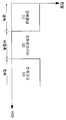
복수개의 전기적 접촉센서들(71)는 도 8b와 같이 소정의 패턴을 가지며 마우스 상부면에 배치되는 복수개의 접촉 패드들(PADS)에 각각 연결되어 전기적 스크롤 장치를 구현한다. 이때 전기적 접촉센서들(71) 각각은 도 6의 전기적 접촉센서(61)에 같이 접촉패드(PAD)에 대한 접촉 물체의 접촉을 감지 및 통보한다.The plurality of
MCU(72)는 복수개의 전기적 접촉 센서들(71)로부터 전송되는 신호들을 조합하여 스크롤 방향을 파악하고, 해당 방향으로 컴퓨터의 디스플레이 화면을 스크롤 할 수 있도록 하는 스크롤 데이터를 발생하여 컴퓨터에 전송한다.The
이에 도 8a의 마우스는 복수개의 전기적 접촉센서들(71)를 통해 사용자의 접촉 위치를 파악하고, MCU(72)를 통해 사용자의 접촉 위치에 대응되는 스크롤 방향을 파악하여, 사용자가 필요로 하는 방향으로 컴퓨터의 디스플레이 화면을 스크롤 하도록 하는 스크롤 데이터를 발생한다.Accordingly, the mouse of FIG. 8A detects the contact position of the user through the plurality of
예를 들어, 사용자가 도 8b와 같이 상하로 일렬 배치된 복수개의 접촉 패드들(PADS) 중 하측에 배치된 일부 접촉 패드들(P5, P6)에만 접촉하면, 이 일부 접촉 패드들(P5, P6)에 대응되는 일부 접촉 센서들만이 하이 레벨을 가지는 출력 신호를 발생한다. 이에 MCU(72)는 복수개의 접촉 패드들(P1~P6) 중 하측에 배치된 일부 접촉 패드들(P5, P6)이 접촉되었음을 감지하고 디스플레이 화면을 아래쪽으로 스크롤 하기 위한 스크롤 데이터를 발생하여 준다.For example, when the user contacts only some of the contact pads P5 and P6 disposed below the plurality of contact pads PADS arranged up and down as shown in FIG. 8B, the partial contact pads P5 and P6 are disposed. Only some contact sensors corresponding to) generate an output signal having a high level. The
도 8a의 마우스 장치는 종래의 기계적 스크롤 장치가 차지하는 공간을 감소시킬 수 있어, 아주 얇은 두께의 마우스 장치의 구현이 가능하고 마모성이 강한 기계적 장치를 제거함으로 장치의 내구성을 증대한다.The mouse device of FIG. 8A can reduce the space occupied by the conventional mechanical scroll device, thereby enabling the implementation of a very thin mouse device and increasing the durability of the device by eliminating the highly wearable mechanical device.
이외에도 도 9a와 도 9b에서와 같이, 도 3의 복수개의 전기적 접촉 센서는 각 전기적 접촉 센서와 연결되는 접촉 패드들(PADS)을 휴대 단말기 또는 MP3 플레이어의 문자 배열판에 소정의 패턴으로 배치하고, 스크롤 장치 또는 위치 추적 장치 또는 위치 입력 장치로써 이용할 수 도 있다.In addition, as shown in FIGS. 9A and 9B, the plurality of electrical contact sensors of FIG. 3 arrange contact pads PADS connected to each electrical contact sensor in a predetermined pattern on a character arrangement board of a mobile terminal or an MP3 player. It can also be used as a scrolling device, a location tracking device, or a location input device.
즉, 사용자가 소정의 패턴으로 배치된 접촉 패드들을 위에서 손가락을 이동시키면 디스플레이 화면에 이 이동을 표시하거나 디스플레이 화면에 표시된 특정 항목을 선택하는 위치 입력 장치로서 이용할 수 도 있다.That is, when the user moves a finger on the contact pads arranged in a predetermined pattern, the touch pad may be used as a position input device that displays the movement on the display screen or selects a specific item displayed on the display screen.
이와 같이 본 발명의 전기적 접촉 센서는 하나의 접촉 패드만을 구비하고, 그 구성이 간단하여 접촉 유무 또는 접촉 위치의 변화를 활용하는 어떠한 장치에 손쉽게 응용될 수 있다.As described above, the electrical contact sensor of the present invention includes only one contact pad, and its configuration is simple, so that it can be easily applied to any device that utilizes the presence or absence of a contact or a change in contact position.
상기에서는 본 발명의 바람직한 실시 예를 참조하여 설명하였지만, 해당 기술 분야의 숙련된 당업자는 하기의 특허 청구의 범위에 기재된 본 발명의 사상 및 영역으로부터 벗어나지 않는 범위 내에서 본 발명을 다양하게 수정 및 변경시킬 수 있음을 이해할 수 있을 것이다.Although the above has been described with reference to a preferred embodiment of the present invention, those skilled in the art will be variously modified and changed within the scope of the invention without departing from the spirit and scope of the invention described in the claims below. I can understand that you can.
따라서 본 발명의 전기적 접촉센서는 전도성이 충분하지 않더라도 일정이상의 전하 축적 능력을 가진 접촉 물체이면 접촉 유무를 정확하게 판단할 수 있도록 하여 동작의 신뢰성을 제공하여 준다. 이는 특히, 날씨의 습도 유무와 사람간이 전도성 차이나 장갑 등의 피복 착용 유무에 상관없이 전기적 접촉센서가 안정적으로 동작 될 수 있도록 하여 준다.Therefore, the electrical contact sensor of the present invention provides a reliability of operation by allowing the contact object to accurately determine the presence or absence of contact, even if the conductivity is not sufficient, even if the contact object has a predetermined charge accumulation capability. This makes it possible to operate the electrical contact sensor stably regardless of the humidity of the weather and the presence or absence of a conductive gap between people or wearing a glove.
또한 전기적 접촉센서는 하나의 접촉 패드만으로도 접촉 물체의 접촉 유무를 판단할 수 있도록 하여 제품의 레이아웃을 감소시켜 줄 수 있다.In addition, the electrical contact sensor can reduce the layout of the product by determining whether the contact object is in contact with only one contact pad.
또한 본 발명의 휴먼 인터페이스 장치는 전기적 접촉 센서를 이용하여 전력 공급을 제어하거나 스크롤 동작하는 것과 같이 보다 향상되고 다양해진 기능을 제공하여 줄 수 있다.In addition, the human interface device of the present invention can provide more improved and various functions, such as controlling a power supply or scrolling using an electrical contact sensor.
Claims (14)
Translated fromKoreanPriority Applications (4)
| Application Number | Priority Date | Filing Date | Title |
|---|---|---|---|
| KR20050023382AKR100666699B1 (en) | 2005-03-21 | 2005-03-21 | Electrical contact sensor and human interface device using the same |
| TW094117777ATWI272539B (en) | 2004-06-03 | 2005-05-31 | Electrical touch sensor and human interface device using the same |
| CN2005100752108ACN1705232B (en) | 2004-06-03 | 2005-06-03 | Electric contact sensor and man-machine interface device using the same |
| US11/145,332US7605805B2 (en) | 2004-06-03 | 2005-06-03 | Electrical touch sensor and human interface device using the same |
Applications Claiming Priority (1)
| Application Number | Priority Date | Filing Date | Title |
|---|---|---|---|
| KR20050023382AKR100666699B1 (en) | 2005-03-21 | 2005-03-21 | Electrical contact sensor and human interface device using the same |
Publications (2)
| Publication Number | Publication Date |
|---|---|
| KR20060101821Atrue KR20060101821A (en) | 2006-09-26 |
| KR100666699B1 KR100666699B1 (en) | 2007-01-09 |
Family
ID=37632783
Family Applications (1)
| Application Number | Title | Priority Date | Filing Date |
|---|---|---|---|
| KR20050023382AExpired - Fee RelatedKR100666699B1 (en) | 2004-06-03 | 2005-03-21 | Electrical contact sensor and human interface device using the same |
Country Status (1)
| Country | Link |
|---|---|
| KR (1) | KR100666699B1 (en) |
Cited By (4)
| Publication number | Priority date | Publication date | Assignee | Title |
|---|---|---|---|---|
| WO2010047445A1 (en)* | 2008-10-24 | 2010-04-29 | 주식회사 애트랩 | Touch sensor device |
| KR100982282B1 (en)* | 2008-09-19 | 2010-09-15 | 주식회사 애트랩 | Sensor, sensor sensing method, and sensor filter |
| US8384695B2 (en) | 2007-06-28 | 2013-02-26 | Atlab Inc. | Automatic impedance adjuster and control method thereof |
| US8456434B2 (en) | 2006-06-22 | 2013-06-04 | Atlab Inc. | Touch sensor and operating method thereof |
Family Cites Families (3)
| Publication number | Priority date | Publication date | Assignee | Title |
|---|---|---|---|---|
| GB9209364D0 (en)* | 1992-04-30 | 1992-06-17 | Varitronix Ltd | A touch sensitive device |
| KR100403680B1 (en)* | 2000-06-24 | 2003-11-01 | 문종섭 | A touch type mouse |
| KR100642497B1 (en)* | 2004-06-03 | 2006-11-02 | 주식회사 애트랩 | Electrical contact sensor |
- 2005
- 2005-03-21KRKR20050023382Apatent/KR100666699B1/ennot_activeExpired - Fee Related
Cited By (5)
| Publication number | Priority date | Publication date | Assignee | Title |
|---|---|---|---|---|
| US8456434B2 (en) | 2006-06-22 | 2013-06-04 | Atlab Inc. | Touch sensor and operating method thereof |
| US8384695B2 (en) | 2007-06-28 | 2013-02-26 | Atlab Inc. | Automatic impedance adjuster and control method thereof |
| KR100982282B1 (en)* | 2008-09-19 | 2010-09-15 | 주식회사 애트랩 | Sensor, sensor sensing method, and sensor filter |
| WO2010047445A1 (en)* | 2008-10-24 | 2010-04-29 | 주식회사 애트랩 | Touch sensor device |
| US8581867B2 (en) | 2008-10-24 | 2013-11-12 | Atlab Inc. | Touch sensor device |
Also Published As
| Publication number | Publication date |
|---|---|
| KR100666699B1 (en) | 2007-01-09 |
Similar Documents
| Publication | Publication Date | Title |
|---|---|---|
| US7605805B2 (en) | Electrical touch sensor and human interface device using the same | |
| US12181943B2 (en) | Reducing sleep current in a capacitance sensing system | |
| JP4014660B2 (en) | Portable computer devices | |
| KR102093021B1 (en) | Electrical device having multi-functional human interface | |
| US8314780B2 (en) | Touch device | |
| US8749523B2 (en) | Methods and apparatus for capacitive sensing | |
| US8860683B2 (en) | Integrated button activation sensing and proximity sensing | |
| US7583092B2 (en) | Capacitive sensing apparatus that uses a combined guard and sensing electrode | |
| US8624609B2 (en) | Two-dimensional position sensor | |
| KR101105279B1 (en) | Touch sensor IC | |
| US20060232559A1 (en) | Capacitive touchpad with physical key function | |
| WO2005043595A3 (en) | Electric field proximity keyboards and detection systems | |
| JPH11511580A (en) | Pressure-sensitive scroll bar function | |
| KR20220145425A (en) | Capacitive sensor and method for determining a touch input stimulus | |
| KR100642497B1 (en) | Electrical contact sensor | |
| KR100666699B1 (en) | Electrical contact sensor and human interface device using the same | |
| KR100949179B1 (en) | Garment type wireless M eye device using conductive fiber | |
| KR20050115704A (en) | Apparatus of generating scroll signal for mouse and mouse using it | |
| US7667693B2 (en) | Touch sensing apparatus using varying signal delay input to a flip-flop | |
| JP2004020210A (en) | Electrostatic capacitance sensor |
Legal Events
| Date | Code | Title | Description |
|---|---|---|---|
| PA0109 | Patent application | St.27 status event code:A-0-1-A10-A12-nap-PA0109 | |
| A201 | Request for examination | ||
| PA0201 | Request for examination | St.27 status event code:A-1-2-D10-D11-exm-PA0201 | |
| D13-X000 | Search requested | St.27 status event code:A-1-2-D10-D13-srh-X000 | |
| D14-X000 | Search report completed | St.27 status event code:A-1-2-D10-D14-srh-X000 | |
| E902 | Notification of reason for refusal | ||
| PE0902 | Notice of grounds for rejection | St.27 status event code:A-1-2-D10-D21-exm-PE0902 | |
| E13-X000 | Pre-grant limitation requested | St.27 status event code:A-2-3-E10-E13-lim-X000 | |
| P11-X000 | Amendment of application requested | St.27 status event code:A-2-2-P10-P11-nap-X000 | |
| P13-X000 | Application amended | St.27 status event code:A-2-2-P10-P13-nap-X000 | |
| PG1501 | Laying open of application | St.27 status event code:A-1-1-Q10-Q12-nap-PG1501 | |
| E701 | Decision to grant or registration of patent right | ||
| PE0701 | Decision of registration | St.27 status event code:A-1-2-D10-D22-exm-PE0701 | |
| GRNT | Written decision to grant | ||
| PR0701 | Registration of establishment | St.27 status event code:A-2-4-F10-F11-exm-PR0701 | |
| PR1002 | Payment of registration fee | St.27 status event code:A-2-2-U10-U11-oth-PR1002 Fee payment year number:1 | |
| PG1601 | Publication of registration | St.27 status event code:A-4-4-Q10-Q13-nap-PG1601 | |
| R18-X000 | Changes to party contact information recorded | St.27 status event code:A-5-5-R10-R18-oth-X000 | |
| PR1001 | Payment of annual fee | St.27 status event code:A-4-4-U10-U11-oth-PR1001 Fee payment year number:4 | |
| PR1001 | Payment of annual fee | St.27 status event code:A-4-4-U10-U11-oth-PR1001 Fee payment year number:5 | |
| PR1001 | Payment of annual fee | St.27 status event code:A-4-4-U10-U11-oth-PR1001 Fee payment year number:6 | |
| FPAY | Annual fee payment | Payment date:20121228 Year of fee payment:7 | |
| PR1001 | Payment of annual fee | St.27 status event code:A-4-4-U10-U11-oth-PR1001 Fee payment year number:7 | |
| FPAY | Annual fee payment | Payment date:20131227 Year of fee payment:8 | |
| PR1001 | Payment of annual fee | St.27 status event code:A-4-4-U10-U11-oth-PR1001 Fee payment year number:8 | |
| R18-X000 | Changes to party contact information recorded | St.27 status event code:A-5-5-R10-R18-oth-X000 | |
| R17-X000 | Change to representative recorded | St.27 status event code:A-5-5-R10-R17-oth-X000 | |
| FPAY | Annual fee payment | Payment date:20150316 Year of fee payment:9 | |
| PR1001 | Payment of annual fee | St.27 status event code:A-4-4-U10-U11-oth-PR1001 Fee payment year number:9 | |
| FPAY | Annual fee payment | Payment date:20151230 Year of fee payment:10 | |
| PR1001 | Payment of annual fee | St.27 status event code:A-4-4-U10-U11-oth-PR1001 Fee payment year number:10 | |
| PN2301 | Change of applicant | St.27 status event code:A-5-5-R10-R11-asn-PN2301 | |
| PN2301 | Change of applicant | St.27 status event code:A-5-5-R10-R11-asn-PN2301 | |
| R18-X000 | Changes to party contact information recorded | St.27 status event code:A-5-5-R10-R18-oth-X000 | |
| P22-X000 | Classification modified | St.27 status event code:A-4-4-P10-P22-nap-X000 | |
| PN2301 | Change of applicant | St.27 status event code:A-5-5-R10-R11-asn-PN2301 | |
| FPAY | Annual fee payment | Payment date:20161229 Year of fee payment:11 | |
| PN2301 | Change of applicant | St.27 status event code:A-5-5-R10-R14-asn-PN2301 | |
| PR1001 | Payment of annual fee | St.27 status event code:A-4-4-U10-U11-oth-PR1001 Fee payment year number:11 | |
| FPAY | Annual fee payment | Payment date:20171228 Year of fee payment:12 | |
| PR1001 | Payment of annual fee | St.27 status event code:A-4-4-U10-U11-oth-PR1001 Fee payment year number:12 | |
| FPAY | Annual fee payment | Payment date:20181227 Year of fee payment:13 | |
| PR1001 | Payment of annual fee | St.27 status event code:A-4-4-U10-U11-oth-PR1001 Fee payment year number:13 | |
| FPAY | Annual fee payment | Payment date:20200103 Year of fee payment:14 | |
| PR1001 | Payment of annual fee | St.27 status event code:A-4-4-U10-U11-oth-PR1001 Fee payment year number:14 | |
| PR1001 | Payment of annual fee | St.27 status event code:A-4-4-U10-U11-oth-PR1001 Fee payment year number:15 | |
| PR1001 | Payment of annual fee | St.27 status event code:A-4-4-U10-U11-oth-PR1001 Fee payment year number:16 | |
| PC1903 | Unpaid annual fee | St.27 status event code:A-4-4-U10-U13-oth-PC1903 Not in force date:20230104 Payment event data comment text:Termination Category : DEFAULT_OF_REGISTRATION_FEE | |
| PN2301 | Change of applicant | St.27 status event code:A-5-5-R10-R13-asn-PN2301 St.27 status event code:A-5-5-R10-R11-asn-PN2301 | |
| P22-X000 | Classification modified | St.27 status event code:A-4-4-P10-P22-nap-X000 | |
| PC1903 | Unpaid annual fee | St.27 status event code:N-4-6-H10-H13-oth-PC1903 Ip right cessation event data comment text:Termination Category : DEFAULT_OF_REGISTRATION_FEE Not in force date:20230104 |