KR20060099520A - Medical Skin Mounting Device - Google Patents
Medical Skin Mounting DeviceDownload PDFInfo
- Publication number
- KR20060099520A KR20060099520AKR1020067008119AKR20067008119AKR20060099520AKR 20060099520 AKR20060099520 AKR 20060099520AKR 1020067008119 AKR1020067008119 AKR 1020067008119AKR 20067008119 AKR20067008119 AKR 20067008119AKR 20060099520 AKR20060099520 AKR 20060099520A
- Authority
- KR
- South Korea
- Prior art keywords
- reservoir
- unit
- transdermal device
- drug
- transdermal
- Prior art date
- Legal status (The legal status is an assumption and is not a legal conclusion. Google has not performed a legal analysis and makes no representation as to the accuracy of the status listed.)
- Withdrawn
Links
- 239000012530fluidSubstances0.000claimsabstractdescription139
- 239000003814drugSubstances0.000claimsabstractdescription98
- 229940079593drugDrugs0.000claimsabstractdescription96
- 238000004891communicationMethods0.000claimsabstractdescription57
- 230000008878couplingEffects0.000claimsabstractdescription22
- 238000010168coupling processMethods0.000claimsabstractdescription22
- 238000005859coupling reactionMethods0.000claimsabstractdescription22
- 238000003780insertionMethods0.000claimsdescription26
- 230000037431insertionEffects0.000claimsdescription26
- 238000003860storageMethods0.000claimsdescription22
- 238000000034methodMethods0.000claimsdescription13
- 239000007788liquidSubstances0.000claimsdescription7
- 238000007789sealingMethods0.000claimsdescription4
- 230000000903blocking effectEffects0.000claimsdescription2
- 230000002427irreversible effectEffects0.000claimsdescription2
- 230000001419dependent effectEffects0.000claims1
- 230000032258transportEffects0.000abstract1
- 239000012528membraneSubstances0.000description30
- 238000001802infusionMethods0.000description25
- 238000002347injectionMethods0.000description21
- 239000007924injectionSubstances0.000description21
- 239000000853adhesiveSubstances0.000description15
- 230000001070adhesive effectEffects0.000description15
- 238000012377drug deliveryMethods0.000description15
- NOESYZHRGYRDHS-UHFFFAOYSA-NinsulinChemical compoundN1C(=O)C(NC(=O)C(CCC(N)=O)NC(=O)C(CCC(O)=O)NC(=O)C(C(C)C)NC(=O)C(NC(=O)CN)C(C)CC)CSSCC(C(NC(CO)C(=O)NC(CC(C)C)C(=O)NC(CC=2C=CC(O)=CC=2)C(=O)NC(CCC(N)=O)C(=O)NC(CC(C)C)C(=O)NC(CCC(O)=O)C(=O)NC(CC(N)=O)C(=O)NC(CC=2C=CC(O)=CC=2)C(=O)NC(CSSCC(NC(=O)C(C(C)C)NC(=O)C(CC(C)C)NC(=O)C(CC=2C=CC(O)=CC=2)NC(=O)C(CC(C)C)NC(=O)C(C)NC(=O)C(CCC(O)=O)NC(=O)C(C(C)C)NC(=O)C(CC(C)C)NC(=O)C(CC=2NC=NC=2)NC(=O)C(CO)NC(=O)CNC2=O)C(=O)NCC(=O)NC(CCC(O)=O)C(=O)NC(CCCNC(N)=N)C(=O)NCC(=O)NC(CC=3C=CC=CC=3)C(=O)NC(CC=3C=CC=CC=3)C(=O)NC(CC=3C=CC(O)=CC=3)C(=O)NC(C(C)O)C(=O)N3C(CCC3)C(=O)NC(CCCCN)C(=O)NC(C)C(O)=O)C(=O)NC(CC(N)=O)C(O)=O)=O)NC(=O)C(C(C)CC)NC(=O)C(CO)NC(=O)C(C(C)O)NC(=O)C1CSSCC2NC(=O)C(CC(C)C)NC(=O)C(NC(=O)C(CCC(N)=O)NC(=O)C(CC(N)=O)NC(=O)C(NC(=O)C(N)CC=1C=CC=CC=1)C(C)C)CC1=CN=CN1NOESYZHRGYRDHS-UHFFFAOYSA-N0.000description10
- 239000010410layerSubstances0.000description8
- 238000005192partitionMethods0.000description8
- 102000004877InsulinHuman genes0.000description5
- 108090001061InsulinProteins0.000description5
- 229940125396insulinDrugs0.000description5
- 230000009471actionEffects0.000description4
- 239000000463materialSubstances0.000description4
- 230000003204osmotic effectEffects0.000description4
- 230000004888barrier functionEffects0.000description3
- 230000008901benefitEffects0.000description3
- 206010012601diabetes mellitusDiseases0.000description3
- 230000000149penetrating effectEffects0.000description3
- 230000008569processEffects0.000description3
- 238000007920subcutaneous administrationMethods0.000description3
- 239000000126substanceSubstances0.000description3
- WQZGKKKJIJFFOK-GASJEMHNSA-NGlucoseNatural productsOC[C@H]1OC(O)[C@H](O)[C@@H](O)[C@@H]1OWQZGKKKJIJFFOK-GASJEMHNSA-N0.000description2
- 229910000831SteelInorganic materials0.000description2
- 239000004809TeflonSubstances0.000description2
- 229920006362Teflon®Polymers0.000description2
- 208000027418Wounds and injuryDiseases0.000description2
- 230000004913activationEffects0.000description2
- 238000003491arrayMethods0.000description2
- 230000000712assemblyEffects0.000description2
- 238000000429assemblyMethods0.000description2
- 230000000740bleeding effectEffects0.000description2
- 239000003795chemical substances by applicationSubstances0.000description2
- 230000006378damageEffects0.000description2
- 238000001514detection methodMethods0.000description2
- 230000006870functionEffects0.000description2
- 239000000499gelSubstances0.000description2
- 239000008103glucoseSubstances0.000description2
- 229940088597hormoneDrugs0.000description2
- 239000005556hormoneSubstances0.000description2
- 208000014674injuryDiseases0.000description2
- 238000005259measurementMethods0.000description2
- 239000002184metalSubstances0.000description2
- 108090000623proteins and genesProteins0.000description2
- 239000004576sandSubstances0.000description2
- 239000010959steelSubstances0.000description2
- 230000001954sterilising effectEffects0.000description2
- 238000004659sterilization and disinfectionMethods0.000description2
- 238000011144upstream manufacturingMethods0.000description2
- XLYOFNOQVPJJNP-UHFFFAOYSA-NwaterSubstancesOXLYOFNOQVPJJNP-UHFFFAOYSA-N0.000description2
- 241001631457CannulaSpecies0.000description1
- 210000001015abdomenAnatomy0.000description1
- 239000013543active substanceSubstances0.000description1
- 239000012790adhesive layerSubstances0.000description1
- 230000003466anti-cipated effectEffects0.000description1
- 239000008280bloodSubstances0.000description1
- 210000004369bloodAnatomy0.000description1
- 230000008859changeEffects0.000description1
- 239000000470constituentSubstances0.000description1
- 238000010276constructionMethods0.000description1
- 230000009849deactivationEffects0.000description1
- 238000013461designMethods0.000description1
- 238000012938design processMethods0.000description1
- 238000010586diagramMethods0.000description1
- 238000006073displacement reactionMethods0.000description1
- 238000001962electrophoresisMethods0.000description1
- 230000009969flowable effectEffects0.000description1
- 230000014509gene expressionEffects0.000description1
- 238000009434installationMethods0.000description1
- 230000007774longtermEffects0.000description1
- 235000012054mealsNutrition0.000description1
- 230000007246mechanismEffects0.000description1
- 238000012544monitoring processMethods0.000description1
- 235000016709nutritionNutrition0.000description1
- 206010033675panniculitisDiseases0.000description1
- 230000037368penetrate the skinEffects0.000description1
- 238000002360preparation methodMethods0.000description1
- 238000003825pressingMethods0.000description1
- 102000004196processed proteins & peptidesHuman genes0.000description1
- 108090000765processed proteins & peptidesProteins0.000description1
- 230000001681protective effectEffects0.000description1
- 102000004169proteins and genesHuman genes0.000description1
- 238000005086pumpingMethods0.000description1
- 230000000241respiratory effectEffects0.000description1
- 239000012266salt solutionSubstances0.000description1
- 238000004904shorteningMethods0.000description1
- 239000007787solidSubstances0.000description1
- 239000000243solutionSubstances0.000description1
- 229910001220stainless steelInorganic materials0.000description1
- 239000010935stainless steelSubstances0.000description1
- 210000004304subcutaneous tissueAnatomy0.000description1
- 238000002560therapeutic procedureMethods0.000description1
- 230000037317transdermal deliveryEffects0.000description1
- 230000000007visual effectEffects0.000description1
- 238000003466weldingMethods0.000description1
Images


Classifications
- A—HUMAN NECESSITIES
- A61—MEDICAL OR VETERINARY SCIENCE; HYGIENE
- A61M—DEVICES FOR INTRODUCING MEDIA INTO, OR ONTO, THE BODY; DEVICES FOR TRANSDUCING BODY MEDIA OR FOR TAKING MEDIA FROM THE BODY; DEVICES FOR PRODUCING OR ENDING SLEEP OR STUPOR
- A61M5/00—Devices for bringing media into the body in a subcutaneous, intra-vascular or intramuscular way; Accessories therefor, e.g. filling or cleaning devices, arm-rests
- A61M5/14—Infusion devices, e.g. infusing by gravity; Blood infusion; Accessories therefor
- A61M5/142—Pressure infusion, e.g. using pumps
- A61M5/14244—Pressure infusion, e.g. using pumps adapted to be carried by the patient, e.g. portable on the body
- A61M5/14248—Pressure infusion, e.g. using pumps adapted to be carried by the patient, e.g. portable on the body of the skin patch type
- A—HUMAN NECESSITIES
- A61—MEDICAL OR VETERINARY SCIENCE; HYGIENE
- A61M—DEVICES FOR INTRODUCING MEDIA INTO, OR ONTO, THE BODY; DEVICES FOR TRANSDUCING BODY MEDIA OR FOR TAKING MEDIA FROM THE BODY; DEVICES FOR PRODUCING OR ENDING SLEEP OR STUPOR
- A61M5/00—Devices for bringing media into the body in a subcutaneous, intra-vascular or intramuscular way; Accessories therefor, e.g. filling or cleaning devices, arm-rests
- A61M5/14—Infusion devices, e.g. infusing by gravity; Blood infusion; Accessories therefor
- A61M5/142—Pressure infusion, e.g. using pumps
- A61M5/14244—Pressure infusion, e.g. using pumps adapted to be carried by the patient, e.g. portable on the body
- A61M5/14248—Pressure infusion, e.g. using pumps adapted to be carried by the patient, e.g. portable on the body of the skin patch type
- A61M2005/14252—Pressure infusion, e.g. using pumps adapted to be carried by the patient, e.g. portable on the body of the skin patch type with needle insertion means
- A—HUMAN NECESSITIES
- A61—MEDICAL OR VETERINARY SCIENCE; HYGIENE
- A61M—DEVICES FOR INTRODUCING MEDIA INTO, OR ONTO, THE BODY; DEVICES FOR TRANSDUCING BODY MEDIA OR FOR TAKING MEDIA FROM THE BODY; DEVICES FOR PRODUCING OR ENDING SLEEP OR STUPOR
- A61M5/00—Devices for bringing media into the body in a subcutaneous, intra-vascular or intramuscular way; Accessories therefor, e.g. filling or cleaning devices, arm-rests
- A61M5/14—Infusion devices, e.g. infusing by gravity; Blood infusion; Accessories therefor
- A61M5/142—Pressure infusion, e.g. using pumps
- A61M5/14244—Pressure infusion, e.g. using pumps adapted to be carried by the patient, e.g. portable on the body
- A61M2005/14268—Pressure infusion, e.g. using pumps adapted to be carried by the patient, e.g. portable on the body with a reusable and a disposable component
- A—HUMAN NECESSITIES
- A61—MEDICAL OR VETERINARY SCIENCE; HYGIENE
- A61M—DEVICES FOR INTRODUCING MEDIA INTO, OR ONTO, THE BODY; DEVICES FOR TRANSDUCING BODY MEDIA OR FOR TAKING MEDIA FROM THE BODY; DEVICES FOR PRODUCING OR ENDING SLEEP OR STUPOR
- A61M5/00—Devices for bringing media into the body in a subcutaneous, intra-vascular or intramuscular way; Accessories therefor, e.g. filling or cleaning devices, arm-rests
- A61M5/14—Infusion devices, e.g. infusing by gravity; Blood infusion; Accessories therefor
- A61M5/142—Pressure infusion, e.g. using pumps
- A61M5/145—Pressure infusion, e.g. using pumps using pressurised reservoirs, e.g. pressurised by means of pistons
- A61M2005/14506—Pressure infusion, e.g. using pumps using pressurised reservoirs, e.g. pressurised by means of pistons mechanically driven, e.g. spring or clockwork
- A—HUMAN NECESSITIES
- A61—MEDICAL OR VETERINARY SCIENCE; HYGIENE
- A61M—DEVICES FOR INTRODUCING MEDIA INTO, OR ONTO, THE BODY; DEVICES FOR TRANSDUCING BODY MEDIA OR FOR TAKING MEDIA FROM THE BODY; DEVICES FOR PRODUCING OR ENDING SLEEP OR STUPOR
- A61M5/00—Devices for bringing media into the body in a subcutaneous, intra-vascular or intramuscular way; Accessories therefor, e.g. filling or cleaning devices, arm-rests
- A61M5/14—Infusion devices, e.g. infusing by gravity; Blood infusion; Accessories therefor
- A61M5/142—Pressure infusion, e.g. using pumps
- A61M5/145—Pressure infusion, e.g. using pumps using pressurised reservoirs, e.g. pressurised by means of pistons
- A61M2005/14513—Pressure infusion, e.g. using pumps using pressurised reservoirs, e.g. pressurised by means of pistons with secondary fluid driving or regulating the infusion
- A—HUMAN NECESSITIES
- A61—MEDICAL OR VETERINARY SCIENCE; HYGIENE
- A61M—DEVICES FOR INTRODUCING MEDIA INTO, OR ONTO, THE BODY; DEVICES FOR TRANSDUCING BODY MEDIA OR FOR TAKING MEDIA FROM THE BODY; DEVICES FOR PRODUCING OR ENDING SLEEP OR STUPOR
- A61M5/00—Devices for bringing media into the body in a subcutaneous, intra-vascular or intramuscular way; Accessories therefor, e.g. filling or cleaning devices, arm-rests
- A61M5/14—Infusion devices, e.g. infusing by gravity; Blood infusion; Accessories therefor
- A61M5/158—Needles for infusions; Accessories therefor, e.g. for inserting infusion needles, or for holding them on the body
- A61M2005/1585—Needle inserters
- A—HUMAN NECESSITIES
- A61—MEDICAL OR VETERINARY SCIENCE; HYGIENE
- A61M—DEVICES FOR INTRODUCING MEDIA INTO, OR ONTO, THE BODY; DEVICES FOR TRANSDUCING BODY MEDIA OR FOR TAKING MEDIA FROM THE BODY; DEVICES FOR PRODUCING OR ENDING SLEEP OR STUPOR
- A61M5/00—Devices for bringing media into the body in a subcutaneous, intra-vascular or intramuscular way; Accessories therefor, e.g. filling or cleaning devices, arm-rests
- A61M5/14—Infusion devices, e.g. infusing by gravity; Blood infusion; Accessories therefor
- A61M5/142—Pressure infusion, e.g. using pumps
- A61M5/14212—Pumping with an aspiration and an expulsion action
- A61M5/14216—Reciprocating piston type
- A—HUMAN NECESSITIES
- A61—MEDICAL OR VETERINARY SCIENCE; HYGIENE
- A61M—DEVICES FOR INTRODUCING MEDIA INTO, OR ONTO, THE BODY; DEVICES FOR TRANSDUCING BODY MEDIA OR FOR TAKING MEDIA FROM THE BODY; DEVICES FOR PRODUCING OR ENDING SLEEP OR STUPOR
- A61M5/00—Devices for bringing media into the body in a subcutaneous, intra-vascular or intramuscular way; Accessories therefor, e.g. filling or cleaning devices, arm-rests
- A61M5/14—Infusion devices, e.g. infusing by gravity; Blood infusion; Accessories therefor
- A61M5/142—Pressure infusion, e.g. using pumps
- A61M5/14212—Pumping with an aspiration and an expulsion action
- A61M5/14224—Diaphragm type
- A—HUMAN NECESSITIES
- A61—MEDICAL OR VETERINARY SCIENCE; HYGIENE
- A61M—DEVICES FOR INTRODUCING MEDIA INTO, OR ONTO, THE BODY; DEVICES FOR TRANSDUCING BODY MEDIA OR FOR TAKING MEDIA FROM THE BODY; DEVICES FOR PRODUCING OR ENDING SLEEP OR STUPOR
- A61M5/00—Devices for bringing media into the body in a subcutaneous, intra-vascular or intramuscular way; Accessories therefor, e.g. filling or cleaning devices, arm-rests
- A61M5/14—Infusion devices, e.g. infusing by gravity; Blood infusion; Accessories therefor
- A61M5/142—Pressure infusion, e.g. using pumps
- A61M5/145—Pressure infusion, e.g. using pumps using pressurised reservoirs, e.g. pressurised by means of pistons
- A61M5/1452—Pressure infusion, e.g. using pumps using pressurised reservoirs, e.g. pressurised by means of pistons pressurised by means of pistons
- A61M5/14526—Pressure infusion, e.g. using pumps using pressurised reservoirs, e.g. pressurised by means of pistons pressurised by means of pistons the piston being actuated by fluid pressure
- A—HUMAN NECESSITIES
- A61—MEDICAL OR VETERINARY SCIENCE; HYGIENE
- A61M—DEVICES FOR INTRODUCING MEDIA INTO, OR ONTO, THE BODY; DEVICES FOR TRANSDUCING BODY MEDIA OR FOR TAKING MEDIA FROM THE BODY; DEVICES FOR PRODUCING OR ENDING SLEEP OR STUPOR
- A61M5/00—Devices for bringing media into the body in a subcutaneous, intra-vascular or intramuscular way; Accessories therefor, e.g. filling or cleaning devices, arm-rests
- A61M5/14—Infusion devices, e.g. infusing by gravity; Blood infusion; Accessories therefor
- A61M5/142—Pressure infusion, e.g. using pumps
- A61M5/145—Pressure infusion, e.g. using pumps using pressurised reservoirs, e.g. pressurised by means of pistons
- A61M5/148—Pressure infusion, e.g. using pumps using pressurised reservoirs, e.g. pressurised by means of pistons flexible, e.g. independent bags
- A61M5/1483—Pressure infusion, e.g. using pumps using pressurised reservoirs, e.g. pressurised by means of pistons flexible, e.g. independent bags using flexible bags externally pressurised by fluid pressure
- A61M5/1486—Pressure infusion, e.g. using pumps using pressurised reservoirs, e.g. pressurised by means of pistons flexible, e.g. independent bags using flexible bags externally pressurised by fluid pressure the bags being substantially completely surrounded by fluid
Landscapes
- Health & Medical Sciences (AREA)
- Heart & Thoracic Surgery (AREA)
- Life Sciences & Earth Sciences (AREA)
- Engineering & Computer Science (AREA)
- Anesthesiology (AREA)
- Biomedical Technology (AREA)
- Veterinary Medicine (AREA)
- Hematology (AREA)
- Vascular Medicine (AREA)
- Animal Behavior & Ethology (AREA)
- General Health & Medical Sciences (AREA)
- Public Health (AREA)
- Dermatology (AREA)
- Infusion, Injection, And Reservoir Apparatuses (AREA)
- Media Introduction/Drainage Providing Device (AREA)
Abstract
Translated fromKoreanDescription
Translated fromKorean본 발명은 일반적으로, 피험자의 피부를 통해 유체를 도입하기 위한 경피 장치를 포함하는, 피험자의 피부 표면에 도포하도록 적합하게 되어 있는 장치에 관한 것이다. 특정한 양태로서, 그러한 장치는 유체 약물을 함유하도록 적합하게 된 저장소, 및 저장소로부터 경피 장치를 거쳐 피험자의 피부를 통해 유체 약물을 방출하는 방출 수단을 포함할 수 있다.The present invention generally relates to a device adapted to be applied to a skin surface of a subject, including a transdermal device for introducing a fluid through the skin of the subject. In certain embodiments, such a device may comprise a reservoir adapted to contain a fluid drug, and a release means for releasing the fluid drug from the reservoir via the transdermal device through the subject's skin.
본 발명의 설명에서는, 대부분 인슐린의 주사 또는 주입에 의한 당뇨병의 치료에 관해 언급되지만, 이것은 단지 본 발명의 예시적인 사용일 뿐이다.In the description of the present invention, reference is made mostly to the treatment of diabetes by injection or infusion of insulin, but this is merely exemplary use of the present invention.
환자에게 약물을 송달하기 위한 휴대용 약물송달 장치가 잘 알려져 있으며, 이것은 일반적으로 중공 주입 바늘과 유체연통된 출구를 갖는 액체 약물을 함유하도록 적합하게 된 저장소와, 뿐만 아니라 저장소로부터 중공 바늘을 거쳐 피험자의 피부를 통해 약물을 방출하는 방출 수단을 포함한다. 그러한 장치는 주로 주입 펌프라고 명명된다.Portable drug delivery devices for drug delivery to a patient are well known, which generally is adapted to contain a liquid drug having an outlet in fluid communication with the hollow injection needle, as well as via a hollow needle from the reservoir, Release means for releasing the drug through the skin. Such a device is mainly named an infusion pump.
기본적으로, 주입 펌프는 두 부류로 분류될 수 있다. 제 1 부류는 3-4년 동안 사용하도록 된 비교적 고가의 펌프인 주입 펌프를 포함하는데, 이 때문에 그러한 펌프에 대한 초기 비용은 종종 이 종류의 치료법에 대한 장벽이 되고 있다. 종 래의 주사기 및 펜보다 더욱 복잡함에도 불구하고, 이 펌프는 인슐린의 연속 주입, 투약 분량의 정확성 및 선택적으로는 식사와 관련하여 프로그래밍 가능한 송달 프로파일 및 사용자에 의해 가동되는 볼루스 주입이라는 이점을 제공한다.Basically, infusion pumps can be classified into two classes. The first class includes infusion pumps, which are relatively expensive pumps intended to be used for 3-4 years, so the initial cost for such pumps is often a barrier to this type of therapy. Despite being more complex than conventional syringes and pens, this pump offers the advantages of continuous infusion of insulin, accuracy of dosage volume and, optionally, a delivery profile programmable by the user in relation to meals and a bolus infusion operated by the user. do.
상기 문제를 다루는데 있어서, 비용이 저렴하고 사용하기 편리한 제 2 부류의 약물주입 장치를 제공하기 위한 몇몇 시도가 행해졌다. 이들 장치의 일부는 부분적으로 또는 완전히 일회용이도록 의도되며, 부수적인 비용 및 불편함 없이 주입 펌프에 관련된 대부분의 이점을 제공할 수 있는데, 예를 들어 이 펌프는 사전-충전됨으로써 약물 저장소를 충전하거나 재충전해야 하는 필요를 피할 수 있다. 이 종류의 주입 장치의 예들은, US 특허 4,340,048 및 4,552,561(삼투 펌프에 기초함), US 특허 5,858,001(피스톤 펌프에 기초함), US 특허 6,280,148(멤브레인 펌프에 기초함), US 특허 5,957,895(유량제한기 펌프(블리딩 홀 펌프라고도 한다)에 기초함), US 특허 5,527,288(가스 발생 펌프에 기초함), 또는 US 특허 5,814,020(팽창성 젤에 기초함)에 공지되어 있는데, 이들은 전부 지난 십 년간, 저렴한, 주로 일회용의 약물주입 장치에서 사용하는 것이 제안되었으며, 인용된 문헌들은 참고자료로서 포함된다. US 특허 6,364,865는 2개의 바이알-형 용기가 연결되어 있고 이 용기들 중 하나에 압력을 가함으로써 이 용기에 함유된 약물이 방출되는 손에 쥐어지는 주입 장치를 개시한다.In addressing this problem, several attempts have been made to provide a second class of infusion device which is inexpensive and easy to use. Some of these devices are intended to be partially or fully disposable and can provide most of the benefits associated with infusion pumps without the associated cost and inconvenience, for example, they may be pre-filled to fill or refill the drug reservoir. The need to dodge can be avoided. Examples of injection devices of this kind include US Pat. Nos. 4,340,048 and 4,552,561 (based on osmotic pumps), US Pat. No. 5,858,001 (based on piston pumps), US Pat. 6,280,148 (based on membrane pumps), US Pat. Air pumps (based on bleeding hole pumps), US Pat. No. 5,527,288 (based on gas generating pumps), or US Pat. No. 5,814,020 (based on expandable gels), all of which have been inexpensive over the past decade, It has been proposed to use mainly in single use infusion devices, and the cited references are incorporated by reference. US Pat. No. 6,364,865 discloses an infusion device in which two vial-type containers are connected and which are pressurized to one of these containers to release the drug contained therein.
일회용 펌프는 일반적으로 접착 수단에 의해 피험자의 피부에 도포하도록 적합하게 된 피부-접촉 장착 표면을 포함하며, 주입 바늘이 사용시에 장착 표면으로부터 나와서 피험자의 피부를 관통하도록 배치되고, 이로써 바늘이 피부를 관통한 장소는 기구를 사용하고 있는 동안 덮여지게 된다. US 특허 2,605,765, 4,340,048 및 EP 1 177 802에 개시된 대로, 주입 바늘은 장착 표면으로부터 영구히 나와 있는 상태로 배치되어 주입 펌프의 도포와 동시에 바늘이 삽입되거나, 또는 US 특허 5, 858,001 및 5,814,020에 개시된 대로, 바늘은 들어간 상태에서, 즉 바늘의 말단의 뾰족한 끝이 펌프 장치 내부에 "숨겨진" 채 장치에 공급될 수 있는데, 이것은 바늘을 관찰해야할 가능성 없이 사용자가 피부 위에 펌프 장치를 놓는 것을 허용한다. 펌프에 더하여, 예를 들어 하기 논의된 이온영동법 등의, 유체 약물을 수송하기 위한 다른 수단도 사용될 수 있다.Disposable pumps generally comprise a skin-contact mounting surface adapted to be applied to the subject's skin by means of adhesion, wherein the injection needle is disposed to penetrate the subject's skin out of the mounting surface in use, thereby allowing the needle to The penetrating site is covered while using the instrument. As disclosed in US Pat. Nos. 2,605,765, 4,340,048 and
상기 설명된 제 2 부류의 완전히 또는 부분적으로 일회용인 주입 장치는 종래의 항구적 주입 펌프보다 상당히 저렴하게 제조될 수 있다는 것이 예상될 수 있지만, 이들은 여전히 매일 사용하기 위한 종래의 주입 펌프에 대한 현실적 대안으로서 사용하기에는 너무 고가인 것으로 여겨지고 있다.It can be expected that the second class of fully or partially disposable infusion devices described above can be manufactured significantly cheaper than conventional permanent infusion pumps, but they are still a viable alternative to conventional infusion pumps for daily use. It is considered too expensive to use.
본 발명의 설명으로 돌아가기 전에, 바늘 또는 바늘-형 구조의 삽입에 의존하는 다른 종류의 장치를 설명할 것이다.Before returning to the description of the present invention, another kind of device that relies on the insertion of a needle or needle-like structure will be described.
일회용이든 항구적인 것이든, 약물주입 펌프는 사용의 편리함 및 개선된 치료 제어를 제공할 수 있음에도, 폐-루프 제어에 의존하는, 즉 어느 정도 완전히 자동인, 예를 들어 당뇨병의 치료를 위한 약물주입 시스템을 제공하려는 목적을 오랫동안 가졌으며, 그러한 시스템은, 예를 들어 당뇨병의 인슐린 치료의 경우에 혈중 글루코스 수준 등의, 치료된 상태를 표시하는 값의 측정에 기초하고 있다.Whether disposable or permanent, the infusion pump can provide ease of use and improved treatment control, but relies on pulmonary-loop control, ie to some extent fully automatic, eg for the treatment of diabetes It has long been aimed at providing a system, which system is based on the measurement of values indicative of the treated state, such as, for example, blood glucose levels in the case of insulin treatment of diabetes.
주어진 물질의 농도를 측정하기 위한 제공되는 모니터 시스템은 침습성 또는 비-침습성 측정 원리에 기초할 수 있다. 후자의 예는 근-IR 분광기를 사용하는 환자의 피부 표면에 배치된 비-침습성 글루코스 모니터인데, 그러나 본 발명은 주로 바늘-형 센서 요소와 같은 경피 장치를 포함하는 장치에 관한 것이다.Provided monitor systems for measuring the concentration of a given substance may be based on invasive or non-invasive measurement principles. An example of the latter is a non-invasive glucose monitor disposed on the skin surface of a patient using a near-IR spectrometer, but the present invention relates primarily to devices comprising transdermal devices such as needle-like sensor elements.
센서는 배선에 의해 외부 장치와 연결되어 피하에 놓일 수 있거나, 또는 분석될 물질(예를 들어, 유체)이 외부 센서 요소로 수송될 수 있는데, 두 배치 모두 피하 구성요소(예를 들어, 작은 카테테르 또는 배관)의 설치를 요하며, 본 발명은 이 두 배치를 모두 다룬다. 그러나, 간단히 하기 위해서, 용어 "센서"는 이후 피험자로 도입되는 두 종류의 요소 모두에 대해 사용된다.The sensor may be connected subcutaneously and placed subcutaneously with an external device by wiring, or the material to be analyzed (eg, fluid) may be transported to an external sensor element, both arrangements of subcutaneous components (eg, small catheters). Installation of a terminator or tubing), and the present invention addresses both arrangements. However, for the sake of simplicity, the term "sensor" is used for both types of elements which are subsequently introduced into the subject.
상기 확인된 문제와 관련하여, 본 발명의 목적은 피부-장착형 약물송달 장치 또는 시스템과 그에 따른 구성요소들을 제공하는 것이며, 그러한 장치 또는 시스템은 편리하게 비용-효과적인 방식으로 사용될 수 있다. 시스템의 구성 및 그에 따른 구성요소들은, 손쉽고 신속한 작동을 허용하며, 또한 사용시 신뢰할 만한, 의료용 송달 수단을 제공하는데 기여해야 한다.In connection with the problem identified above, it is an object of the present invention to provide a skin-mounted drug delivery device or system and its components, which device or system can be conveniently used in a cost-effective manner. The configuration of the system, and thus the components, should allow for easy and quick operation and also contribute to providing a reliable medical delivery means in use.
본 발명의 설명에서, 구체예 및 양태들이 설명될 것인데, 이들은 상기 목적 중 하나 이상을 다루거나, 또는 하기 설명 및 예시적인 구체예의 설명으로부터 명백한 목적들을 다룰 것이다.In the description of the invention, embodiments and aspects will be described, which will address one or more of the above objects, or will address the objects that are apparent from the following description and the description of exemplary embodiments.
이에 따라, 제 1 양태에 상응하여, 경피 유닛 및 저장소 유닛을 포함하는 의료 장치가 제공되며, 여기서 경피 유닛은 피험자의 피부 부분을 통해 유체를 송달하는 경피 수단, 및 피험자의 피부에 도포하도록 적합하게 된 장착 표면을 포함한다. 저장소 유닛은 유체 약물을 함유하도록 적합하게 된 저장소, 및 사용시에 저장소로부터 경피 수단을 거쳐 피험자의 피부를 통해 유체 약물을 방출하는 방출 수단을 포함하며, 상기 저장소는 경피 수단이 저장소의 내부와 유체연통하여 배치되도록 하는 출구를 포함한다. 경피 유닛 및 저장소 유닛은 사용시에 저장소 유닛이 경피 유닛에 고정되도록 하는 결합 수단을 더 포함할 수 있다.Accordingly, in accordance with the first aspect, there is provided a medical device comprising a transdermal unit and a reservoir unit, wherein the transdermal unit is suitably adapted for application to transdermal means for delivering fluid through a skin portion of a subject and to the subject's skin Included mounting surface. The reservoir unit includes a reservoir adapted to contain a fluid drug, and a release means for use to release the fluid drug from the reservoir via the transdermal means through the skin of the subject, wherein the reservoir is in fluid communication with the interior of the reservoir. An outlet to be disposed through. The transdermal unit and the reservoir unit may further comprise coupling means for securing the reservoir unit to the transdermal unit in use.
용어 "경피"는, 예를 들어 피내 또는 피하 투여 등의, 피부의 일부분을 통해 유체가 수송되는 모든 형태의 투여를 아우른다. 경피 수단은 경피 장치, 분사 주사 수단, 또는 이온영동법의 원리를 사용하여 피험자의 피부 표면의 정해진 부위에서 피하 조직으로 이온 제제가 침투하도록 하는 전극의 형태일 수 있다. 이온영동법에 대한 더 철저한 논의는 본원에 참고자료로서 포함된 US 특허 6,622,037에 언급된다. 경피 수단의 성질에 의존하여, 방출 수단은 상이한 구성 및 성질을 가질 수 있다. 예를 들어, 하나 이상의 중공 주입 바늘이나 캐뉼러가 사용될 때, 방출 수단은 저장소로부터 유체 약물을 강제로 밀어내거나 빨아내도록 배치될 수 있고, 한편 전기영동법의 경우에 방출 수단은 전극 셋트에 전류를 인가하는 수단, 즉 "구동" 수단일 수 있다.The term "transdermal" encompasses all forms of administration in which fluid is transported through portions of the skin, such as, for example, intradermal or subcutaneous administration. Transdermal means may be in the form of transdermal devices, jet injection means, or electrodes that allow ionic agents to penetrate into subcutaneous tissue at defined sites on the subject's skin surface using the principles of iontophoresis. A more thorough discussion of iontophoresis is mentioned in US Pat. No. 6,622,037, incorporated herein by reference. Depending on the nature of the transdermal means, the release means can have different configurations and properties. For example, when one or more hollow injection needles or cannulas are used, the release means may be arranged to forcibly push or suck out the fluid drug from the reservoir, while in the case of electrophoresis the release means applies a current to the electrode set. Means, ie "drive" means.
추가 양태에 상응하여, 경피 장치 유닛 및 저장소 유닛을 포함하는 의료 장치가 제공되며, 여기서 경피 장치 유닛은 경피 장치, 및 피험자의 피부에 도포하도록 적합하게 된 장착 표면을 포함한다. 저장소 유닛은 유체 약물을 함유하도록 적합하게 된 저장소, 및 저장소와 협력하여 저장소로부터 경피 장치를 거쳐 피험자의 피부를 통해 유체 약물을 방출하도록 적합하게 된 방출 조립체를 포함한다. 더 나아가, 경피 장치 유닛 및 저장소 유닛은 사용시에 서로 고정되도록 적합하게 되며, 이로써 저장소와 경피 장치 간에 유체연통이 확립되는 것을 허용한다. 경피 장치 유닛 및 저장소 유닛은 사용시에 저장소 유닛이 경피 장치 유닛에 고정되도록 하는 해제가능한 결합 수단을 포함할 수 있다. 2개의 유닛을 포함하는 그러한 의료 장치는 또한 의료 시스템으로 간주될 수 있다. 경피 장치 유닛 및 저장소 유닛은 그 내부에 경피 장치 및 저장소 및 방출 조립체가 각각 배치되는 하우징을 각각 포함할 수 있다.According to a further aspect, there is provided a medical device comprising a transdermal device unit and a reservoir unit, wherein the transdermal device unit comprises a transdermal device and a mounting surface adapted to be applied to the subject's skin. The reservoir unit includes a reservoir adapted to contain the fluid drug and a release assembly adapted to cooperate with the reservoir to release the fluid drug from the reservoir via the transdermal device and through the skin of the subject. Furthermore, the transdermal device unit and the reservoir unit are adapted to be secured to each other in use, thereby allowing fluid communication to be established between the reservoir and the transdermal device. The transdermal device unit and the reservoir unit may comprise releasable engagement means to secure the reservoir unit to the transdermal device unit in use. Such a medical device comprising two units may also be considered a medical system. The transdermal device unit and the reservoir unit may each include a housing in which the transdermal device and the reservoir and discharge assembly are respectively disposed.
용어 "방출 조립체"는 조합된 상태에서 유체가 저장소로부터 방출될 수 있는 것을 제공하는 구성요소들 또는 구조들의 집합체를 아우른다. 방출 조립체는, 예를 들어 전기 제어식 가동 수단과 조합된 기계적 펌프(예를 들어, 멤브레인 펌프, 피스톤 펌프 또는 롤러 펌프), 기계적 구동 펌프(예를 들어, 스프링에 의한 구동), 가스 구동 펌프 또는 삼투 엔진에 의해 구동되는 펌프일 수 있다. 또한, 방출 조립체는, 방출 조립체가 방출 조립체 외부의 컨트롤러에 의해 제어되거나 구동될 때, 조합된 상태에서 유체가 저장소로부터 방출될 수 있는 것을 제공하는 구성요소들 또는 구조들의 집합체의 형태일 수 있다.The term "release assembly" encompasses a collection of components or structures that provide that the fluid can be released from the reservoir in a combined state. The discharge assembly can be, for example, a mechanical pump (eg membrane pump, piston pump or roller pump), mechanically driven pump (eg driven by spring), gas driven pump or osmosis in combination with electrically controlled actuation means. It may be a pump driven by an engine. Further, the release assembly may be in the form of a collection of components or structures that provide that fluid can be released from the reservoir in a combined state when the release assembly is controlled or driven by a controller external to the release assembly.
경피 장치(이 용어는 또한 본 기술분야에서 종래부터 사용되는 유사한 용어인 경피적 접근 장치 및 경피적 접근 도구를 아우른다)는 첨형 중공 주입 바늘, 미세바늘 어레이, 또는 비교적 유연한 그 자체는 굵은 캐뉼러와 첨형 경피 장치를 제공할 수 있는 첨형 삽입 바늘의 조합일 수 있으며, 이 삽입 바늘은 경피 장치의 굵은 부분의 삽입 후에 후퇴될 수 있다. 후자의 경우, 피험자에게 실제로 놓여진 다음 본원에 설명된 후퇴 수단에 의해 후퇴되는 경피 장치의 부분은, 조합된 경피 장치가 피부를 통해 삽입되는 것을 허용하는 첨형 단부를 반드시 포함하는 것은 아니며, 그러한 첨형 단부는 경피 장치의 삽입 동안에 뒤로 물러난다. 캐뉼러는 전형적으로 단단한 스틸 바늘인 삽입 바늘에 비해 부드럽고 유연한 것이 유리하다. 본 발명의 설명 및 예시적인 구체예의 설명에서는 대부분 주입 바늘의 형태인 경피 장치에 관해 언급될 것이다. 경피 장치의 길이는 실제 용도에 따라서 선택될 수 있는데, 예를 들어 피부 표면에 대해 실질적으로 직각으로 삽입될 수 있는 중공 스틸 바늘은 2-8mm, 바람직하게 3-5mm의 삽입 길이를 가질 수 있는 반면, 또한 피부 표면에 대해 사각으로 삽입될 수 있는 캐뉼러는, 예를 들어 4-20mm로 다소 더 길 수 있다.Percutaneous devices (the term also encompasses percutaneous access devices and percutaneous access tools, similar terms conventionally used in the art) are pointed hollow injection needles, microneedle arrays, or relatively flexible by themselves thick cannula and pointed transdermal It may be a combination of cusp insertion needles that may provide the device, which may be retracted after insertion of the thick portion of the transdermal device. In the latter case, the portion of the transdermal device that is actually placed on the subject and then retracted by the retraction means described herein does not necessarily include a sharp end that allows the combined transdermal device to be inserted through the skin, and such a sharp end Retracts during insertion of the transdermal device. The cannula is advantageously soft and flexible compared to the insertion needle, which is typically a rigid steel needle. In the description of the invention and in the description of the exemplary embodiments, reference will be made to transdermal devices, which are mostly in the form of injection needles. The length of the transdermal device can be selected according to the actual application, for example a hollow steel needle that can be inserted substantially perpendicular to the skin surface can have an insertion length of 2-8 mm, preferably 3-5 mm, The cannula, which can also be inserted square to the skin surface, can be somewhat longer, for example 4-20 mm.
장착 표면은 피험자(예를 들어, 사용자 또는 환자)의 피부에 대해 도포하도록 적합하게 되어 있으며, 장착 표면 외부의 부착 수단(예를 들어, 의료 장치가 피부 장착 장치와 결합되는 것을 허용하는 결합 수단, 또는 접착식 반창고나 붕대)에 의해 또는 장착 표면에 제공된 접착 수단에 의해 피부와 접촉된 상태로 고정될 수 있다. 또, 장착 표면은 피부 장착 장치의 개재된 구성요소에 의해서 피부를 향해 장착되도록 적합하게 될 수 있는데, 예를 들어 피부 장착 장치는 의료 장치가 부착되는 수용부를 포함할 수 있고, 경피 장치가 이 수용부에 있는 구멍을 통해 피부에 삽입된다.The mounting surface is adapted to apply to the skin of a subject (eg a user or a patient), the attachment means external to the mounting surface (eg, coupling means to allow the medical device to engage the skin mounting device, Or adhesive bandages or bandages) or by means of adhesion provided on the mounting surface. In addition, the mounting surface may be adapted to be mounted toward the skin by intervening components of the skin mounting device, for example the skin mounting device may comprise a receptacle to which the medical device is attached, wherein the transdermal device is adapted to receive this. It is inserted into the skin through a hole in the department.
상기 배치에 의해 상이한 구상들이 실현될 수 있다. 예를 들어, 유닛의 하나를 적어도 2개의 상이한 종류로 제공함으로써, 2가지 이상의 조합을 제공하는 것이 가능할 것이며, 여기서 조립체를 제공하는 경피 장치 유닛과 저장소 유닛의 각 조합은 하기 더 상세히 논의된 것처럼 상이한 능력을 가질 것이다. 유닛들이 해제가능한 결합 수단과 함께 제공되는 경우에, 유닛 중 하나는 나머지 유닛이 재사용되는 것을 여전히 허용하면서 새로운 또는 상이한 유닛으로 교환될 수 있으며, 이로써 재사용되는 유닛의 작동수명이 연장된다. 이와 같이, 예시적인 구체예에서, 본 발명은 사용자와의 인터페이스를 제공하는 구성요소는 제 1 유닛에 통합되는 한편, 그 자체가 약물송달을 제공하는 구성요소는 제 2 유닛에 통합된 장치를 제공하며, 이것은 조합되는 구성요소들이 간단하고 신뢰할 수 있고 사용하기 쉬운 방식으로 조합되거나 교환되는 것을 허용한다.Different arrangements can be realized by this arrangement. For example, by providing one of the units in at least two different types, it would be possible to provide two or more combinations, where each combination of transdermal device unit and reservoir unit providing the assembly is different as discussed in more detail below. Will have the ability. If the units are provided with releasable coupling means, one of the units can be exchanged for a new or different unit while still allowing the other unit to be reused, thereby extending the operational life of the reused unit. As such, in an exemplary embodiment, the present invention provides an apparatus in which a component providing an interface with a user is integrated in a first unit while a component in itself providing drug delivery is integrated in a second unit. This allows the components to be combined to be combined or exchanged in a simple, reliable and easy to use manner.
예를 들어, 저장소 유닛은 어떤 양의 약물 및 예를 들어 10일에 걸쳐 약물이 송달되도록 하는 에너지원을 포함하는 송달 펌프와 함께 제공될 수 있고, 한편 경피 장치 유닛은 경피 장치 및 2일의 예상된(또는 권장된) 작동수명을 갖는 장착 표면상의 접착면과 함께 제공될 수 있고, 이것은 저장소 유닛이 10일의 기간에 걸쳐 5개의 경피 장치 유닛과 함께 사용되는 것을 허용하며, 이 조합된 장치를 사용하여 총 비용이 상당히 저하된다. 저장소는 사전-충전되거나, 또는 1회 이상 충전되도록 적합하게 될 수 있다.For example, the reservoir unit may be provided with a delivery pump that contains a certain amount of drug and an energy source that allows the drug to be delivered, for example, over 10 days, while the transdermal device unit is a transdermal device and 2 days anticipated It may be provided with an adhesive surface on a mounting surface having a recommended (or recommended) operating life, which allows the reservoir unit to be used with five transdermal device units over a period of 10 days, The total cost of use is significantly reduced. The reservoir may be pre-filled or adapted to be filled one or more times.
한편, 경피 장치 유닛은, 예를 들어 바늘 또는 소프트 캐뉼러, 및 바늘 유닛이 장착되고 연장된 시간 기간에 걸쳐 사용되는 것을 허용하는 접착 수단(예를 들어, 콜로스토미 백을 부착하는데 사용되는 종류의)과 함께 제공될 수 있으며, 저장소 유닛은, 예를 들어 비교적 다량의 약물이 주입되어야 할 때는 단축된 예상된 작동수명을 가진다. 또는 달리, 상이한 종류의 약물을 갖는 상이한 저장소 유닛들이 그러한 "장기" 장착된 바늘 유닛과 조합하여 사용될 수 있다.On the other hand, the transdermal device unit may be, for example, of a needle or soft cannula, and of adhesive means (e.g., used to attach a collotomy bag) that allows the needle unit to be mounted and used over an extended period of time. ), The reservoir unit has a shortened expected life expectancy, for example when a relatively large amount of drug has to be injected. Alternatively, different reservoir units with different kinds of drugs can be used in combination with such "long-term" mounted needle units.
사용의 용이함을 위해서, 바늘 유닛과 저장소 유닛이 서로 고정된 때 바늘과 저장소 간의 유체연통이 확립될 수 있으며, 마찬가지로 바늘 유닛과 저장소 유닛이 서로 고정된 때 방출 수단이 활성화되고, 유닛들이 서로 해제될 때 비활성화될 수 있다. 실제로, 또, 이 작동법들 중 하나 또는 모두는 사용자에 의해 수동으로 수행될 수 있다.For ease of use, fluid communication between the needle and the reservoir can be established when the needle unit and the reservoir unit are fixed to each other, likewise when the needle unit and the reservoir unit are fixed to each other, the ejection means are activated and the units are released from each other. Can be deactivated. Indeed, again, one or both of these operations can be performed manually by the user.
예시적인 구체예에서, 방출 조립체는 저장소의 출구와 유체연통하여 배치되도록 적합하게 된 입구, 및 경피 장치와 유체연통하여 배치되도록 적합하게 된 출구를 포함하며, 이로써 경피 장치는 저장소의 내부와 유체연통하여 배치되게 된다. 그러한 배치에 의해, 펌프는 저장소로부터 약물을 빼내는 흡입 펌프로서 작용할 것이고, 따라서 저장소는 접을 수 있거나, 접을 수 없는 저장소가 사용되는 경우에는 통풍구가 있어야 할 것이다. 또한, 방출 조립체는 저장소를 가압하도록 적합하게 된 배치, 예를 들어 위치변환 가능한 피스톤을 포함하는 저장소 내의 피스톤을 구동시키는 배치의 형태일 수 있다. 저장소 유닛은 1개 이상의 저장소 및 1개 이상의 방출 조립체를 포함할 수 있다. 예를 들어, 단일 방출 조립체를 사용하여, 동시에 약물을 혼합하면서, 또는 교대로, 1개 이상의 저장소로부터 약물을 방출할 수 있거나, 또는 각 저장소는 공통 경피 장치 또는 별도의 경피 장치와 연결될 수 있는 방출 조립체와 함께 제공될 수 있는데, 예를 들어 경피 장치 유닛은 방출 조립체와 연결되도록 적합하게 된 1개 이상의 경피 장치를 포함할 수 있다.In an exemplary embodiment, the discharge assembly includes an inlet adapted to be placed in fluid communication with the outlet of the reservoir, and an outlet adapted to be placed in fluid communication with the transdermal device, such that the transdermal device is in fluid communication with the interior of the reservoir. Will be placed through. By such an arrangement, the pump will act as an intake pump to withdraw the drug from the reservoir, so that the reservoir will be collapsible or there must be a vent if the non-collapsible reservoir is used. In addition, the release assembly may be in the form of an arrangement adapted to pressurize the reservoir, for example, an arrangement for driving a piston in the reservoir including a repositionable piston. The reservoir unit may comprise one or more reservoirs and one or more discharge assemblies. For example, a single release assembly may be used to release drugs from one or more reservoirs while simultaneously mixing the drugs, or alternately, or each reservoir may be associated with a common transdermal device or a separate transdermal device. It may be provided with the assembly, for example the transdermal device unit may comprise one or more transdermal devices adapted to be connected with the release assembly.
펌프를 통한 초기 멸균 유동 경로를 제공하기 위해서, 유동 경로가 입구와 출구 사이에 배치될 수 있으며, 이로써 입구와 출구가 펌프의 내부를 밀봉함으로써 유동 경로를 초기 멸균 상태로 밀봉한다. 이 배치에 의해서, 완전히 멸균된 유닛으로서 저장소 유닛을 제공하는 것은 불필요할 것이다 - 실제로 약물은 멸균 상태로 제공되어야 할 것이다.To provide an initial sterile flow path through the pump, a flow path can be disposed between the inlet and the outlet, whereby the inlet and the outlet seal the interior of the pump to seal the flow path to the initial sterile state. With this arrangement, it would be unnecessary to provide the reservoir unit as a fully sterilized unit-in fact the drug would have to be provided sterile.
예시적인 구체예에서, 저장소 유닛은 펌프와 저장소 간에 유체연통되어 있지 않은 초기 상태에서, 펌프 유닛이 최초로 바늘 유닛에 고정된 때 펌프의 입구 수단과 저장소의 출구 수단 간에 유체연통이 확립된 비가역적 작동 상태로 변형가능하다. 이 배치에 의해서, 펌프와 저장소 사이의 재-연결 동안 바람직하지 않은 물질이 저장소로 도입되는 것이 피해진다.In an exemplary embodiment, in an initial state where the reservoir unit is not in fluid communication between the pump and the reservoir, irreversible operation in which fluid communication is established between the inlet means of the pump and the outlet means of the reservoir when the pump unit is first secured to the needle unit It can be transformed into a state. This arrangement avoids the introduction of undesirable substances into the reservoir during the re-connection between the pump and the reservoir.
펌프와 저장소 사이의 완전한 연결을 확보하기 위해서, 초기 상태에서 펌프의 내부에 별도의 유체연결장치가 배치될 수 있다. 그러한 유체연결장치는 첨형 입구 단부 및 출구를 포함할 수 있고, 한편 펌프의 입구 및 저장소의 출구는 2개의 바늘-관통가능한 격벽의 형태일 수 있다. 이 배치에 의해서, 유체연결장치의 첨형 단부, 예를 들어 연결 바늘은 2개의 격벽을 통과함으로써, 초기 상태와 유체연결장치에 의해 저장소의 내부와 펌프의 외부 간에 유체연통이 확립된 작동 상태 사이에서 이동될 수 있으며, 유체연결장치의 출구는 유동 경로에 배치된다. 유리하게는, 저장소 유닛이 최초로 경피 장치 유닛에 연결되었을 때, 유체연결장치가 그것의 두 위치 사이에서 이동된다. 상응하여, 그러한 최초 연결 동안 2개의 유체연통이 확립될 것이고(경피 장치의 경피 장치와 펌프 사이, 그리고 펌프와 저장소 사이), 후속 연결 동안에는 단지 1개의 새로운 유체연통이 확립될 것이다(경피 장치 유닛의 경피 장치와 펌프 사이에).To ensure a complete connection between the pump and the reservoir, a separate fluid connection can be arranged inside the pump in its initial state. Such a fluid connection device may comprise a sharp inlet end and an outlet, while the inlet of the pump and the outlet of the reservoir may be in the form of two needle-penetrating bulkheads. With this arrangement, the sharp end of the fluidic connection, for example the connection needle, passes through two bulkheads, thereby providing a connection between the initial state and an operating state in which fluid communication is established between the interior of the reservoir and the outside of the pump by the fluidic connection. It can be moved, and the outlet of the fluidic connector is disposed in the flow path. Advantageously, when the reservoir unit is first connected to the transdermal device unit, the fluid connection device is moved between its two positions. Correspondingly, during such initial connection two fluid communication will be established (between the transdermal device and the pump of the transdermal device and between the pump and the reservoir) and only one new fluid communication will be established during the subsequent connection (of the transdermal device unit). Between the transdermal device and the pump).
예시적인 구체예에서, 경피 장치는 첨형 원단부를 갖는 제 1 부분, 및 제 1 부분과 유체연통되고 제 2 단부를 갖는 제 2 부분을 포함한다. 유리하게는, 경피 장치의 제 2 단부는 첨형이고, 펌프의 출구 수단은, 바람직하게는 두 유닛이 서로 연결되었을 때, 경피 장치의 제 2 단부와 펌프의 내부 간에 유체연통이 확립되도록 허용하는 바늘-관통가능한 격벽을 포함한다.In an exemplary embodiment, the transdermal device includes a first portion having a sharp distal end and a second portion in fluid communication with the first portion and having a second end. Advantageously, the second end of the transdermal device is sharp, and the outlet means of the pump preferably has a needle which allows fluid communication to be established between the second end of the transdermal device and the interior of the pump when the two units are connected to each other. A penetrating bulkhead.
상응하여, 추가의 양태로서, 본 발명은 유체 공급원과 유체연통하여 배치되도록 적합하게 된 입구 수단, 및 출구 수단을 갖는 펌프를 제공하며, 펌프는 입구 수단과 출구 수단 사이에 배치된 내부 유동 경로를 포함하고, 입구 및 출구 수단이 펌프의 내부를 밀봉함으로써 유동 경로를 초기 멸균 상태로 밀봉하며, 여기서 유체 연결 수단은 초기 상태에서 펌프의 내부에 배치되고, 유체 연결 수단은 입구 단부 및 출구를 포함하는데, 이에 따라 유체 연결 수단은 초기 상태와 입구 단부가 펌프 입구 수단으로부터 나와 있는 작동 상태 사이에서 이동되도록 배치되고, 따라서 유체 연결 수단을 거쳐 유체 공급원과 펌프 내부 간에 유체연통이 확립될 수 있으며, 유체 연결 수단의 출구는 유동 경로에 배치된다.Correspondingly, as a further aspect, the present invention provides a pump having an inlet means and an outlet means adapted to be placed in fluid communication with a fluid source, the pump comprising an internal flow path disposed between the inlet means and the outlet means. Wherein the inlet and outlet means seal the flow path in an initial sterile state by sealing the interior of the pump, wherein the fluid connection means are disposed inside the pump in the initial state, the fluid connection means comprising an inlet end and an outlet Thus, the fluid connection means are arranged such that the initial state and the inlet end are moved between the operating state exiting the pump inlet means, so that fluid communication can be established between the fluid source and the pump interior via the fluid connection means, and fluid connection The outlet of the means is arranged in the flow path.
경피 장치 유닛은, 예를 들어 장착 표면으로부터 나와 있는 바늘과 함께 공급될 수 있지만, 우연한 바늘에 의한 상처의 위험을 제한하기 위해서, 경피 장치의 첨형 단부는 첨형 단부가 장착 표면에 대하여 들어가 있는 초기 위치와 첨형 단부가 장착 표면에 대하여 나와 있는 뻗어나간 위치 사이에서 이동가능한 것이 유리하다. 사용자에게 장치를 장착하는 의도된 방법에 의존하여, 경피 장치는 두 유닛이 서로 연결되었을 때 두 위치 사이에서 이동될 수 있고, 마찬가지로 경피 장치 유닛이 사용자의 피부 위에 장착된 후 저장소 유닛이 연결되는 경우도 적합할 것이다. 그러나, 두 유닛이 서로 연결된 후에 조립된 유닛이 사용자의 피부 위에 장착되도록 의도된 경우에는, 경피 장치 유닛은 초기 위치와 뻗어나간 위치 사이에서 경피 장치의 첨형 단부를 이동시키는 사용자-가동가능한 가동 수단을 포함하는 것이 유리하다.The transdermal device unit may, for example, be supplied with a needle emerging from the mounting surface, but in order to limit the risk of injury by accidental needles, the cusp end of the transdermal device may be placed in an initial position with the cusp end entering the mounting surface. It is advantageous for the cusp end to be movable between the extended position with respect to the mounting surface. Depending on the intended method of mounting the device to the user, the transdermal device may be moved between two positions when the two units are connected to each other, likewise when the storage unit is connected after the transdermal device unit is mounted on the user's skin Would also be suitable. However, in the case where the assembled unit is intended to be mounted on the user's skin after the two units are connected to each other, the transdermal device unit may have user-operable movable means for moving the cusp end of the transdermal device between the initial position and the extended position. It is advantageous to include.
두 유닛이 조립되기 전에 경피 장치가 우연히 가동되는 것을 방지하기 위해서, 경피 장치 유닛은 가동 수단을 차단하는 수단을 포함할 수 있으며, 차단 수단은 경피 장치 유닛과 저장소 유닛이 서로 고정된 때 해제됨으로써 가동 수단이 가동되게 된다.In order to prevent the transdermal device from inadvertently running before the two units are assembled, the transdermal device unit may comprise means for shutting off the actuating means, the blocking means being actuated by being released when the transdermal device and the reservoir unit are fixed to each other. The means is activated.
더 이상으로, 경피 장치 상처의 가능성을 줄이기 위해서, 경피 장치의 첨형 단부는, 첨형 단부가 장착 표면에 대하여 나와 있는 뻗어나간 위치와, 첨형 단부가 장착 표면에 대하여 들어가 있는 후퇴 위치 사이에서 이동가능할 수 있다. 상응하여, 조합된 장치는 뻗어나간 위치와 후퇴 수단이 가동된 때의 후퇴 위치 사이에서 경피 장치의 첨형 단부를 이동시키는 사용자-가동가능한 후퇴 수단을 포함할 수 있다. 경피 장치의 재-사용을 방지하기 위해서, 경피 장치는 그것의 후퇴된 위치에서 영구적으로 고정된다.Further, to reduce the likelihood of transdermal device injuries, the cusp end of the transdermal device may be movable between an extended position where the cusp end emerges relative to the mounting surface and a retracted position where the cusp end enters against the mounting surface. have. Correspondingly, the combined device may comprise user-operable retracting means for moving the cusp end of the transdermal device between the extended position and the retracted position when the retracting means are actuated. To prevent re-use of the transdermal device, the transdermal device is permanently fixed in its retracted position.
사용자에 의한 실수를 방지하기 위해서, 경피 장치를 도입하기 위한 가동 수단은 초기 상태에서 후퇴 수단을 덮고 있을 수 있고, 가동 수단의 가동이 후퇴 수단을 노출시킨다. 예를 들어, 가동 수단은 잡는 수단(예를 들어, 스트립)의 형태일 수 있으며, 이것이 장치로부터 제거됨으로써 경피 장치 삽입을 개시하는 동시에 경피 장치를 뒤로 물러나게 하는 후퇴 수단을 노출시킨다.In order to prevent mistakes by the user, the movable means for introducing the transdermal device may be covering the retracting means in an initial state, and the operation of the movable means exposes the retracting means. For example, the movable means may be in the form of a grasping means (eg, a strip), which is removed from the device to initiate the transdermal device insertion and at the same time expose the retracting means to withdraw the transdermal device.
상기 설명된 대로, 방출 조립체는 두 유닛이 조립 및 해체되는 때 활성화 및 비활성화될 수 있지만, 또한 가동 및 후퇴 수단을 사용하여 방출 조립체를 활성화 및 비활성화시킬 수도 있다. 마찬가지로, 펌프와 저장소 사이의 초기 연결에 대해서, 방출 조립체의 초기 활성화는 전자적 제어 수단을 활성화시켜 펌프 작용을 시작시킬 수 있고, 한편 이어지는 비활성화는, 제어 수단은 여전히 활성인 상태(예를 들어, 제어 수단의 초기 활성화 이후의 시간을 카운트하는 것)로 실제 펌프 작용만을 비활성화할 것이다.As described above, the release assembly may be activated and deactivated when both units are assembled and disassembled, but may also be activated and deactivated using the actuation and retraction means. Likewise, for the initial connection between the pump and the reservoir, the initial activation of the discharge assembly may activate the electronic control means to initiate the pump action, while subsequent deactivation may result in the control means being still active (e.g., control Counting the time since the initial activation of the means) will only deactivate the actual pumping action.
본 발명의 상기 설명에서, 2개 유닛은 주로 "단일" 유닛으로 설명되었지만, 이것은 단지 예시적인 구성일 뿐이며, 만일의 경우 이들 2개의 "주" 유닛은 더 이상의 유닛들로 세분되는 것이 바람직할 수 있다고 생각될 수 있다. 예를 들어, 저장소 유닛은 교환가능한 제어 유닛과 함께 제공될 수 있으며, 이것은 상이한 종류의 제어 유닛들이 저장소 유닛 자체에 연결되는 것을 허용하는데, 예를 들어 제 1 종류의 제어 유닛이 한 송달 프로파일을 제공하고, 제 2 제어 유닛은 송달 패턴을 변경하도록 프로그래밍될 수 있거나, 또는 제 3 제어 유닛은 제어 유닛이 외부 수단과 연통되도록 하는 수단을 포함할 수 있다. 후자의 경우, 제어 유닛은 전지식 리모트 컨트롤을 사용하여 제어될 수 있다. 상응하여, 저장소는 상이한 크기의 저장소들 또는 상이한 종류의 약물들이 사용될 수 있도록 교환가능할 수 있다.In the above description of the invention, the two units have been described primarily as "single" units, but this is only an exemplary configuration, in which case it may be desirable for these two "main" units to be subdivided into further units. It can be thought of. For example, the storage unit may be provided with an exchangeable control unit, which allows different kinds of control units to be connected to the storage unit itself, for example the first kind of control unit provides a delivery profile. In addition, the second control unit can be programmed to change the delivery pattern, or the third control unit can comprise means for causing the control unit to communicate with external means. In the latter case, the control unit can be controlled using the battery remote control. Correspondingly, the reservoirs may be exchangeable so that different sized reservoirs or different kinds of drugs may be used.
본 발명의 추가의 양태로서, 경피 장치 유닛이 상기 설명된 대로 제공되며, 상기 개시된 저장소 유닛과 조합하여 사용되도록 적합하게 된다. 상응하여, 본 발명은 또한 상기 개시된 저장소 유닛을 제공하며, 이 저장소 유닛은 상기 개시된 경피 장치 유닛과 조합하여 사용되도록 적합하게 된다. 예시적인 구체예에서, 그러한 경피 장치 유닛은, 피험자의 피부를 관통하도록 적합하게 된 출구 개구를 갖는 첨형 원단부, 및 유체 입구 수단을 형성하는 입구 개구를 갖는 첨형 근단부를 포함하는 중공 바늘과 함께 제공될 수 있으며, 유체 입구 수단은 유체 공급원과 유체연통하여 배치되도록 적합하게 되어 있다. 이 배치에 의해서, 바늘은 바늘 입구 개구와 출구 개구(예를 들어, 금속으로 제조된) 사이에 유압 강직 유체연통을 제공하며, 이것은 압력이 가해지는 바늘의 상류를 모니터함에 의한 초기 폐색 검출을 허용한다.In a further aspect of the invention, a transdermal device unit is provided as described above and is adapted to be used in combination with the reservoir unit disclosed above. Correspondingly, the present invention also provides a reservoir unit as described above, which reservoir unit is adapted to be used in combination with the disclosed transdermal device unit. In an exemplary embodiment, such transdermal device unit is provided with a hollow needle comprising a sharp distal end with an outlet opening adapted to penetrate the subject's skin, and a sharp proximal end with an inlet opening forming a fluid inlet means. And the fluid inlet means is adapted to be placed in fluid communication with the fluid source. By this arrangement, the needle provides hydraulic rigid fluid communication between the needle inlet opening and the outlet opening (eg, made of metal), which allows for initial occlusion detection by monitoring the upstream of the needle under pressure. do.
또 추가의 양태로서, 적어도 1개의 추가의 상기 개시된 바늘 유닛 및 저장소 유닛과 조합된 상기 개시된 제 1 바늘 유닛 및 제 1 저장소 유닛을 포함하는 시스템이 제공되며, 상기 추가의 유닛(들)은 제 1 유닛과는 상이한 능력을 가진다. 상이한 능력은 유닛의 어떤 구성적 특징, 예를 들어 바늘의 종류, 사용자-가동가능한 수단의 종류, 송달/펌프 수단의 종류, 또는 저장소/약물의 종류에 관한 것일 수 있다.In a still further aspect, there is provided a system comprising the disclosed first needle unit and first reservoir unit in combination with at least one further disclosed needle unit and reservoir unit, wherein the additional unit (s) is provided in a first manner. It has different abilities than units. The different capabilities may relate to certain constituent features of the unit, such as the type of needle, type of user-operable means, type of delivery / pump means, or type of reservoir / drug.
더 구체적으로, 예시적인 구체예에서, 상기 개시된 경피 장치 유닛, 및 복수 개의 저장소 유닛을 포함하는 시스템이 제공되며, 저장소 유닛 각각은 유체 약물을 함유하는 저장소, 및 저장소로부터 유체 약물을 방출하는 방출 조립체를 포함한다. 경피 장치 유닛 및 저장소 유닛은, 저장소 유닛을 경피 장치 유닛에 고정시켜 저장소와 경피 장치 간에 유체연통이 제공되도록 하는 맞물리는 결합 수단을 포함하며, 여기서 경피 장치 유닛과 저장소 유닛의 각 조합은 상이한 능력을 갖는 조립체를 제공한다. 상이한 능력은, 예를 들어 동일한 약물의 상이한 양을 갖는 저장소 유닛, 상이한 약물들 또는 주어진 약물의 변형체를 갖는 저장소 유닛, 상이한 사전-설정된 속도로 약물을 방출하도록 적합하게 된 저장소 유닛, 고정되고 선택가능한 속도로 방출하도록 적합하게 된 저장소 유닛을 제공하여 실현될 수 있다. 저장소 유닛 중 1개는 방출 조립체를 제어하는 프로세서 및 별도의 제어 장치로부터 유동 명령을 수신하고 이 유동 명령을 프로세서로 송달하는 컨트롤러와 짝을 이루어 작동될 수 있는 수신기와 함께 제공될 수 있다. 수신기는 무선 수신기일 수 있다. 추가로, 저장소 유닛은 상이한 투입 수단(예를 들어, 무선 또는 유선 연결, 또는 수동 투입을 위한), 또는 상이한 배출 수단(예를 들어, 무선 또는 유선 연결, 상이한 디스플레이 수단, 또는 상이한 알람 수단을 위한)과 함께 제공될 수 있다.More specifically, in an exemplary embodiment, a system is provided that includes the transdermal device unit disclosed above, and a plurality of reservoir units, each reservoir unit containing a fluid drug, and a release assembly that releases the fluid drug from the reservoir. It includes. The transdermal device unit and the reservoir unit include interlocking coupling means for securing the reservoir unit to the transdermal device unit so that fluid communication is provided between the reservoir and the transdermal device, wherein each combination of the transdermal device unit and the reservoir unit has different capabilities. It provides an assembly having. Different capacities are, for example, reservoir units with different amounts of the same drug, reservoirs with different drugs or variants of a given drug, reservoir units adapted to release the drug at different pre-set rates, fixed and selectable It can be realized by providing a storage unit adapted to release at a rate. One of the reservoir units may be provided with a processor that controls the discharge assembly and a receiver that can be operated in pairs with a controller that receives a flow command from a separate control device and delivers the flow command to the processor. The receiver may be a wireless receiver. In addition, the storage unit may be configured for different input means (eg for a wireless or wired connection, or for manual input), or for different discharge means (eg for a wireless or wired connection, for different display means, or for different alarm means. ) May be provided together.
추가의 예시적인 구체예에서, 복수 개의 상기 설명된 경피 장치 유닛, 및 유체 약물을 함유하는 저장소, 및 저장소로부터 유체 약물을 방출하는 방출 조립체를 포함하는 저장소 유닛을 포함하는 시스템이 제공된다. 경피 장치 유닛 및 저장소 유닛은 경피 장치 유닛을 저장소 유닛에 고정시켜 저장소와 경피 장치 간에 유체연통이 제공되도록 하는 맞물리는 결합 수단을 포함하며, 여기서 경피 장치 유닛과 저장소 유닛의 각 조합은 상이한 능력을 갖는 조립체를 제공한다. 상이한 능력은 중공 피하용 바늘, 캐뉼러와 삽입 바늘 조립체, 및 미세바늘 어레이와 같은 상이한 경피 장치를 갖는 경피 장치 유닛을 제공함으로써, 상이한 접착제를 제공함으로써, 상이한 삽입 또는 후퇴 수단을 제공함으로써, 또는 상이한 결합 수단을 제공함으로써 실현될 수 있다.In a further exemplary embodiment, a system is provided that includes a plurality of the transdermal device units described above, and a reservoir containing a fluid drug, and a reservoir unit that releases the fluid drug from the reservoir. The transdermal device unit and the reservoir unit include interlocking coupling means for securing the transdermal device unit to the reservoir unit such that fluid communication is provided between the reservoir and the transdermal device, wherein each combination of the transdermal device unit and the reservoir unit has different capabilities. Provide an assembly. Different capabilities may be achieved by providing transdermal device units with different transdermal devices such as hollow hypodermic needles, cannula and insertion needle assemblies, and microneedle arrays, by providing different adhesives, by providing different insertion or retraction means, or by different It can be realized by providing a coupling means.
또 다른 예시적인 구체예에서, 경피 장치 및 피험자의 피부에 도포하도록 적합하게 된 장착 표면을 포함하는 경피 장치 유닛, 유체 약물을 함유하는 저장소 및 저장소로부터 유체 약물을 방출하는 방출 조립체의 적어도 일부분을 포함하는 저장소 유닛, 및 복수 개의 제어 유닛을 포함하는 시스템이 제공되며, 제어 유닛 각각은 방출 조립체를 제어하는 컨트롤러를 포함하고, 상이한 능력을 가진다. 경피 장치 유닛 및 저장소 유닛은 저장소 유닛을 경피 장치 유닛에 고정시켜 저장소와 경피 장치 간에 유체연통이 제공되도록 하는 맞물리는 결합 수단을 포함하고, 컨트롤러 유닛 및 저장소 유닛은 컨트롤러 유닛을 저장소 유닛에 고정시켜 방출 조립체를 제어하도록 하는 맞물리는 결합 수단을 포함하며, 이로써 경피 장치 유닛, 저장소 유닛 및 제어 유닛의 각 조합은 상이한 능력을 갖는 조립체를 제공한다. 제어 유닛은 복수 개의 저장소 유닛을 포함하는 시스템에 관하여 상기 설명된 것과 마찬가지로 상이한 제어 기능을 가질 수 있다. 다른 구성에서는, 저장소 유닛과 경피 장치 유닛이 제어 유닛과 협력하도록 적합하게 된 단일 구조로서 제공될 수 있다.In another exemplary embodiment, a transdermal device unit comprising a transdermal device and a mounting surface adapted to be applied to the subject's skin, a reservoir containing the fluid drug and at least a portion of the release assembly for releasing the fluid drug from the reservoir There is provided a system comprising a storage unit, and a plurality of control units, each of the control units including a controller for controlling the discharge assembly, and having different capabilities. The transdermal device unit and the storage unit include interlocking coupling means for securing the storage unit to the transdermal device unit to provide fluid communication between the reservoir and the transdermal device, wherein the controller unit and the storage unit secure the controller unit to the storage unit to discharge. Interlocking coupling means for controlling the assembly, whereby each combination of transdermal device unit, reservoir unit and control unit provides an assembly with different capabilities. The control unit can have different control functions as described above with respect to a system comprising a plurality of storage units. In other arrangements, the reservoir unit and the transdermal device unit may be provided as a single structure adapted to cooperate with the control unit.
또한, 본 발명은 경피 장치와 장착 표면을 포함하는 경피 장치 유닛을 제공하는 단계, 유체 약물을 함유하도록 적합하게 된 저장소와 저장소로부터 유체 약물을 방출하는 방출 조립체를 포함하는 저장소 유닛을 제공하는 단계를 포함하는 방법을 제공하며, 이 방법은 경피 장치 유닛과 저장소 유닛을 조립하여 저장소와 경피 장치 사이에 유체연통을 제공하는 단계를 더 포함한다. 경피 장치와 저장소 간의 유체연통은 두 유닛이 조립된 때 확립될 수 있거나, 또는 조립된 장치가 가동된 때 또한 확립될 수 있으며, 두 옵션 모두 상기 정의에 의해 포함된다. 상기 방법은 피험자의 피부 표면에 장착 표면을 장착하는 단계와, 피험자의 피부 표면에 장착 표면을 장착한 후, 경피 장치를 가동시켜 저장소와 피험자 간에 유체연통을 확립하는 단계를 더 포함할 수 있다.The present invention also provides a transdermal device unit comprising a transdermal device and a mounting surface, a reservoir unit comprising a reservoir adapted to contain a fluid drug and a release assembly for releasing the fluid drug from the reservoir. And a method for assembling the transdermal device unit and the reservoir unit to provide fluid communication between the reservoir and the transdermal device. Fluid communication between the transdermal device and the reservoir can be established when both units are assembled, or can also be established when the assembled device is activated, both options being covered by the above definition. The method may further comprise mounting the mounting surface to the subject's skin surface, and after mounting the mounting surface to the subject's skin surface, operating the transdermal device to establish fluid communication between the reservoir and the subject.
더 이상의 방법은 사전-설정된 속도로 약물을 분배하는 약물송달 장치를 제공하며, 이 방법은 경피 장치 및 피험자의 피부에 도포하도록 적합하게 된 장착 표면을 포함하는 경피 장치 유닛을 포함하고, 복수 개의 저장소 유닛을 더 포함하는 시스템을 제공하는 단계, 원하는 사전-설정된 속도를 갖는 저장소 유닛을 선택하는 단계, 및 경피 장치 유닛과 선택된 저장소 유닛을 조립하여 저장소와 경피 장치 간에 유체연통을 제공하는 단계를 포함하며, 상기 저장소 유닛 각각은 유체 약물을 함유하는 저장소, 및 사전-설정된 속도로 저장소로부터 유체 약물을 방출하는 방출 조립체를 포함한다.A further method provides a drug delivery device for dispensing a drug at a pre-set rate, the method comprising a transdermal device unit comprising a transdermal device and a mounting surface adapted to be applied to the subject's skin, the plurality of reservoirs Providing a system further comprising a unit, selecting a reservoir unit having a desired preset speed, and assembling the transdermal device unit and the selected reservoir unit to provide fluid communication between the reservoir and the transdermal device; Each of the reservoir units includes a reservoir containing the fluid drug, and a release assembly that releases the fluid drug from the reservoir at a pre-set rate.
상기 설명에서, 본 발명은 약물송달 장치에 관하여 설명되었지만, 본 발명의 개념은 많은 이점을 제공하는 모듈형 시스템으로 간주될 수 있다. 따라서, 또한, 경피 장치 유닛은 바늘 센서의 형태일 수 있고, 상응하여 "저장소 유닛"은 센서에 의해 획득된 데이터를 전송 및/또는 처리하도록 적합하게 된 장치의 형태일 수 있다.In the above description, the present invention has been described with respect to a drug delivery device, but the concept of the present invention can be regarded as a modular system that provides many advantages. Thus, the transdermal device unit may also be in the form of a needle sensor, and the corresponding “storage unit” may be in the form of a device adapted to transmit and / or process data obtained by the sensor.
본원에 사용된 용어 "약물"은, 액체, 용액, 젤 또는 미세 현탁액과 같은, 제어된 방식으로 중공 바늘과 같은 송달 수단을 통해 지나갈 수 있는 어떤 약물-함유 유동성 의약을 포함하도록 의도된다. 대표적인 약물은 펩티드, 단백질, 및 호르몬 등의 제약, 생물학적으로 유래된 또는 활성인 제제, 호르몬 및 유전자 기반 제제, 영양식 및 고체(조제된) 또는 액체 형태의 다른 물질들을 포함한다. 예시적인 구체예의 설명에서는 인슐린의 사용에 관해 언급될 것이다. 상응하여, 용어 "피하" 주입은 피험자에게 경피 송달하는 어떤 방법을 포함하도록 의도된다. 더 나아가, 용어 "바늘"(달리 명시되지 않았을 때)은 피험자의 피부를 관통하도록 적합하게 된 관통 부재를 정의한다.As used herein, the term “drug” is intended to include any drug-containing flowable medicament that can pass through a delivery means such as a hollow needle in a controlled manner, such as a liquid, solution, gel or microsuspension. Representative drugs include pharmaceuticals such as peptides, proteins, and hormones, biologically derived or active agents, hormones and gene based agents, nutritional and other substances in solid (formulated) or liquid form. In the description of exemplary embodiments, reference will be made to the use of insulin. Correspondingly, the term "subcutaneous" infusion is intended to include any method of transdermal delivery to a subject. Further, the term "needle" (unless otherwise specified) defines a penetrating member adapted to penetrate the subject's skin.
다음에, 본 발명은 도면을 참조하여 더 설명될 것이다.Next, the present invention will be further described with reference to the drawings.
도 1-11은 약물송달 장치의 제 1 구체예의 사용 순서의 투시도를 나타낸다.1-11 show perspective views of the order of use of the first embodiment of the drug delivery device.
도 12는 저장소 유닛의 추가 구체예를 나타낸다.12 shows a further embodiment of the storage unit.
도 13은 약물송달 장치의 추가 구체예에서 바늘 유닛과 저장소 유닛의 비-조립 상태를 나타낸다.FIG. 13 shows the non-assembled state of the needle unit and the reservoir unit in a further embodiment of the drug delivery device.
도 14는 도 13의 바늘 유닛의 분해조립도를 나타낸다.FIG. 14 shows an exploded view of the needle unit of FIG. 13.
도 15는 도 13의 바늘 유닛의 제 1 상태의 투시도를 나타낸다.FIG. 15 shows a perspective view of the first state of the needle unit of FIG. 13.
도 16은 도 14의 바늘 캐리어의 투시도를 나타낸다.FIG. 16 shows a perspective view of the needle carrier of FIG. 14.
도 17은 도 13의 바늘 유닛의 제 2 상태의 투시도를 나타낸다.17 shows a perspective view of a second state of the needle unit of FIG. 13.
도 18은 도 13의 바늘 유닛의 측면도를 나타낸다.18 shows a side view of the needle unit of FIG. 13.
도 19는 도 13의 바늘 유닛의 추가의 투시도를 나타낸다.FIG. 19 shows a further perspective view of the needle unit of FIG. 13.
도 20은 도 13의 저장소 유닛의 내부의 투시도를 나타낸다.20 shows a perspective view of the interior of the storage unit of FIG. 13.
도 21은 추가의 저장소 유닛의 분해조립도를 나타낸다.21 shows an exploded view of a further reservoir unit.
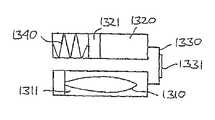
도 22A는 저장소에 연결된 펌프의 도식적 개략도를 나타낸다.22A shows a schematic schematic of a pump connected to a reservoir.
도 22B는 펌프 조립체의 분해조립도를 나타낸다.22B shows an exploded view of the pump assembly.
도 22C는 도 22C의 펌프 조립체의 단면도를 나타낸다.22C shows a cross-sectional view of the pump assembly of FIG. 22C.
도 22D 및 22E는 도 22C의 펌프 조립체의 부분적 단면도를 나타낸다.22D and 22E show partial cross-sectional views of the pump assembly of FIG. 22C.
도 23A 및 23B는 캐뉼러와 삽입 바늘 조합의 형태의 경피 장치를 도식적으로 나타낸다.23A and 23B schematically illustrate the transdermal device in the form of a cannula and insertion needle combination.
도 24는 추가 약물송달 장치의 투시도를 나타낸다.24 shows a perspective view of a further drug delivery device.
도 25A-25D는 본 발명과 함께 사용하기에 적합한 상이한 방출 수단들을 나타낸다.25A-25D show different release means suitable for use with the present invention.
도 26은 모듈형 저장소 유닛을 구비한 의료 장치를 나타낸다.26 shows a medical device with a modular reservoir unit.
도 27은 의료 장치용의 모듈형 시스템을 나타낸다.27 shows a modular system for a medical device.
도면에서 같은 구조는 같은 부재번호에 의해 주로 나타낸다.In the drawings, the same structure is mainly indicated by the same member number.
예시적인 구체예의 설명Description of Exemplary Embodiments
다음에 "상부" 및 "하부", "우측" 및 "좌측", "수평" 및 "수직"과 같은 용어나 유사한 관련 표현들이 사용될 때, 이들은 단지 첨부된 도면에 관한 것이며 실제 사용 상황에 관한 것이 아니다. 나타낸 도면들은 도식적 표현이며, 이 때문에 상이한 구조들의 구성뿐만 아니라 그것의 상대적 치수는 단지 예시적인 목적으로 사용되도록 의도된다.Next, when terms such as "upper" and "lower", "right" and "left", "horizontal" and "vertical" or similar related expressions are used, they are only with reference to the accompanying drawings and that they relate to the actual use situation. no. The figures shown are schematic representations, whereby the construction of different structures as well as their relative dimensions are intended to be used only for illustrative purposes.
먼저, 도 1-12를 참조하여, 직접적으로 사용자 지향적인 특징들에 주로 초점을 맞춘 약물송달 장치의 구체예가 설명될 것이다. 이 경피 장치 유닛(2)은 중공 주입 바늘 형태의 경피 장치를 포함하며, 따라서 이후 바늘 유닛으로 칭해질 것이지만, 이 바늘은 유체 약물의 송달에 적합한 어떤 바람직한 경피 장치로 교체될 수도 있다.First, referring to FIGS. 1-12, an embodiment of a drug delivery device focusing primarily on user-oriented features will be described. This
더 구체적으로, 도 1은 패치-형 바늘 유닛(2)과 저장소 유닛(5)을 포함하는 모듈형 피부-장착형 약물송달 장치(1) 형태의 의료 장치의 투시도를 나타낸다. 사용자에게 공급될 때, 각 유닛은 그 자신의 밀봉 패키지(도시하지 않음) 내에 넣어지는 것이 바람직하다.More specifically, FIG. 1 shows a perspective view of a medical device in the form of a modular skin-mounted
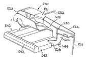
바늘 유닛은 사용자의 피부에 도포하도록 적합하게 된 하부 장착 표면을 갖는 기저부(10), 및 그 내부에 중공 주입 바늘(도시하지 않음)이 배치되는 하우징부(20)를 포함한다. 바늘은 사용자의 피부를 관통하도록 적합하게 된 첨형 원단부를 갖는 제 1 바늘 부분, 및 저장소 유닛과 유체연통하여 배치되도록 적합하게 된 제 2 첨형 단부를 포함한다. 나타낸 구체예에서, 바늘의 첨형 단부는 첨형 단부가 장착 표면에 대하여 들어가 있는 초기 위치와 첨형 단부가 장착 표면에 대하여 나와 있는 뻗어나간 위치 사이에서 이동가능하다. 더 나아가, 바늘은 첨형 단부가 장착 표면에 대하여 나와 있는 뻗어나간 위치와 첨형 단부가 장착 표면에 대하여 들어가 있는 후퇴 위치 사이에서 이동가능하다. 더 이상으로, 바늘 유닛은, 가동 수단이 가동된 때 초기 위치와 제 2 위치 사이에서 바늘의 첨형 단부를 이동시키는 제 1 스트립-부재(21) 형태의 사용자가 잡을 수 있는 가동 수단, 및 후퇴 수단이 가동된 때 뻗어나간 위치와 후퇴 위치 사이에서 바늘의 첨형 단부를 이동시키는 제 2 스트립-부재(22) 형태의 사용자가 잡을 수 있는 후퇴 수단을 포함한다. 보여진 대로, 제 2 스트립은 초기에는 제 1 스트립에 의해 덮여있다. 더 나아가, 하우징은 저장소 유닛 상의 상응하는 암 결합 수단과 협력하도록 적합하게 된 한 쌍의 탄력적으로 배치된 후크 부재 형태의 사용자-가동가능한 수 결합 수단(40)을 포함하며, 이것은 사용시에 저장소 유닛이 바늘 유닛에 해제가능한 식으로 고정되는 것을 허용한다. 나타낸 구체예에서, 기저부는 장착 표면 자체를 제공하는 하부 접착 표면을 갖는 보다 유연한 접착 시트 부재(12)에 부착된 상대적으로 단단한 상부 부분(11)을 포함하며, 접착 표면은 박리가능한 보호 시트와 함께 공급된다. 또한, 기저부는 저장소 유닛 상의 상응하는 홈과 맞물리도록 적합하게 된 릿지 부재(13)를 포함한다.The needle unit includes a base 10 having a lower mounting surface adapted to be applied to a user's skin, and a
저장소 유닛(5)은 액체 약물 조제물(예를 들어, 인슐린)을 함유하는 사전-충전 저장소 및 사용시에 바늘을 통해 저장소로부터 약물을 방출하는 전자 제어식 펌프 형태의 방출 수단을 포함한다. 저장소 유닛은 일반적으로 기저부의 상부 표면 위에 장착되도록 적합하게 된 평평한 하부 표면을 가지며, 하우징부(20)의 상응하는 공동 내에 수용되도록 적합하게 된 돌출부(50)와, 뿐만 아니라 바늘 유닛 상의 상응하는 후크 부재(31)와 맞물리도록 적합하게 된 암 결합 수단(51)을 포함한다. 돌출부는 두 유닛 간의 인터페이스를 제공하며, 펌프 출구 및 두 유닛이 조립된 때 펌프가 시동되도록 하는 접촉 수단(도시하지 않음)을 포함한다. 또한, 하부 표면은 사용자가 저장소의 내용물을 시각적으로 제어하도록 허용하는 창(도시하지 않 음)을 포함한다.The
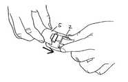
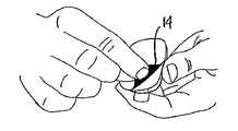
장착 과정의 제 1 단계는 바늘 유닛과 맞물리도록 저장소 유닛을 단순히 미끄러트려 넣음으로써 두 유닛을 조립하는 것이다(도 2). 후크 부재가 저장소 유닛과 적합하게 맞물렸을 때 두 유닛이 적합하게 조립되었다는 것을 사용자에게 알리는 "찰칵"하는 소리가 들린다(도 3). 또, 바람직하다면 시각 또는 청각 신호가 발생될 수 있다. 그 다음 사용자는 박리가능한 시트(14)를 제거하여 접착 표면을 노출시키고(도 4), 그 후 장치는 사용자의 피부 표면에, 전형적으로는 복부에 부착될 수 있다(도 5). 약물의 주입은 화살표로 표시한 대로 가동 스트립(21)을 잡고 그것을 잡아당김으로써 시작되는데, 이로써 바늘이 삽입되고 이어서 주입이 자동으로 시작된다(도 6). 바늘 삽입 메커니즘은 사전-압박된 상태에서 공급되고 그 다음에 가동 수단에 의해 해제될 수 있거나, 또는 바늘 삽입은 사용자에 의해 "활성화"될 수 있다. "발신음" 신호가 장치가 작동중이며 약물이 주입되고 있다는 것을 확인시킨다. 저장소 유닛은, 예를 들어 폐색, 펌프 장애 또는 내용물이 종료된 경우 사용자에게 청각적 알람 신호를 제공하는 신호 수단 및 검출 수단과 함께 제공되는 것이 바람직하다.The first step in the mounting process is to assemble both units by simply sliding the reservoir unit into engagement with the needle unit (FIG. 2). When the hook member is properly engaged with the storage unit, a "click" is heard to inform the user that the two units are properly assembled (Figure 3). Again, a visual or auditory signal can be generated if desired. The user then removes the peelable sheet 14 to expose the adhesive surface (FIG. 4), after which the device can be attached to the skin surface of the user, typically the abdomen (FIG. 5). Injection of the drug is started by grasping the
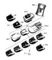
장치는 바늘 유닛의 사용에 알맞은 권장된 시간 기간(예를 들어, 48시간) 동안 제자리에 놓여 있은 다음에, - 또는 저장소가 비는 경우나 다른 이유 때문에 - 바늘 유닛이 화살표로 표시한 대로 후퇴 수단(22)을 잡고(도 7) 그것을 잡아당김(도 8)으로써 피부로부터 제거되는데, 이로써 바늘은 후퇴하게 되고 이어서 약물 주입이 자동으로 중지되며, 그 후 접착 패치에 부착된 스트립을 사용하여 피부 표면 으로부터 장치를 제거한다(도 9).The device is left in place for a recommended time period (e.g. 48 hours) suitable for the use of the needle unit, and-or if the reservoir is empty or for other reasons-as retracting means as indicated by the needle unit as indicated by the arrow. (22) is removed from the skin by holding it (FIG. 7) and pulling it (FIG. 8), which causes the needle to retract and then the drug injection is automatically stopped and then the skin surface using a strip attached to the adhesive patch. Remove the device from (FIG. 9).
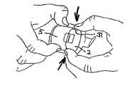
장치가 제거되었을 때, 두 유닛은 화살표로 표시한 대로(도 10) 2개의 후크 부재(31)를 동시에 누름으로써 연결이 풀어지는데, 이로써 화살표로 표시한 대로(도 11) 저장소 유닛(5)은 바늘 유닛(2)과의 맞물린 상태로부터 잡아 당겨져 나오게 되고, 바늘 유닛은 그 다음에 폐기될 수 있다. 그 후, 저장소 유닛은 그것이 빌 때까지 새로운 바늘 유닛과 함께 다시 사용될 수 있다.When the device is removed, the two units are disconnected by simultaneously pressing the two
저장소 유닛은 고정된 기초 주입 속도를 갖도록 공급될 수 있거나, 또는 의사 및/또는 사용자/환자에 의해 주입 속도가 설정되도록 하는 조절 수단(55)을 구비한 조절가능한 유닛(도 12)으로서 공급될 수 있다. 또한, 저장소 유닛은 제어 수단이 전자적으로 프로그래밍되거나 설정되도록 하는 수단과 함께 제공될 수 있다(도시하지 않음).The reservoir unit may be supplied with a fixed basal infusion rate or may be supplied as an adjustable unit (FIG. 12) with an adjusting means 55 to allow the infusion rate to be set by the physician and / or user / patient. have. The storage unit may also be provided with means for causing the control means to be electronically programmed or set up (not shown).
또한, 도 1-11을 참조하여 설명된 장치는 다른 방식으로 사용될 수도 있다. 예를 들어, 바늘 유닛이 피부에 장착된 후에 저장소가 부착될 수 있다. 바늘 유닛의 구성에 의존하여, 저장소 유닛이 부착되기 전에 바늘이 도입되는 것이 가능하거나 또는 방지될 수 있다.Also, the apparatus described with reference to FIGS. 1-11 may be used in other ways. For example, the reservoir may be attached after the needle unit is mounted to the skin. Depending on the configuration of the needle unit, it may be possible or prevented that the needle is introduced before the reservoir unit is attached.
도 13은 도 1의 구체예에 실질적으로 상응하는 의료 장치(500)의 더 이상의 구체예를 나타내는데, 이 장치는 패치-형 바늘 유닛(502)과 거기에 부착가능한 저장소 유닛(505)을 포함한다.FIG. 13 shows a further embodiment of the medical device 500 substantially corresponding to the embodiment of FIG. 1, which includes a patch-
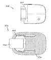
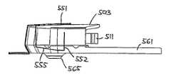
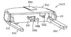
도 14는 상부 하우징부(510), 바늘 캐리어(520)와 거기에 장착되는 주입 바늘(530), 가동 부재(540), 해제 부재(550), 하부 하우징부(560) 및 시트 부재(570) 를 포함하는 바늘 유닛의 분해조립투시도를 나타낸다. 가동 부재는 사용자가 잡을 수 있는 부분(541)과 바늘 가동부(542)를 포함하고, 해제 부재는 사용자가 잡을 수 있는 부분(551)과 바늘 후퇴부(552)를 포함한다. 도 15에 나타낸 조립 상태에서, 상부 및 하부 하우징부는 그 안에 바늘 및 바늘 캐리어가 장착되는 하우징(503)을 형성하고, 가동 및 해제 부재가 바늘 캐리어에 연결되어 작동될 수 있으며, 사용자가 잡을 수 있는 부분은 하우징의 바깥쪽으로 배치된다. 도 1의 구체예와 반대로, 바늘 유닛은 기저 판부를 포함하지 않지만, 대신에 2개의 릿지 부재(561)가 하우징으로부터 뻗어있고, 이 릿지 부재 및 하우징의 하부 표면이 유연한 시트 부재 상에 장착되고, 이 시트 부재는 바늘 유닛이 피험자의 피부 부위에 부착되도록 하는 그것의 하부 표면 상의 하부 접착층(571)과 함께 제공된다. 시트 부재는 경피 장치의 출구 구멍 주위에 제공된 하부 돌출부(565)를 갖는 레지스터 내에 배치되는 개구(572)를 더 포함하고, 마찬가지로 시트는 시트를 통한 호흡력을 개선하기 위해서 다수의 작은 바늘구멍들과 함께 제공된다. 하우징(503)은 저장소 유닛이 바늘 유닛(505)에 부착되고 그것으로부터 해제되는 것을 허용하는 사용자-가동가능한 결합 수단(511)과 함께 제공되고, 저장소 유닛은 상응하는 맞물리는 결합 수단(506) 및 디스플레이(587)을 포함한다. 디스플레이는, 예를 들어 적합한 유닛 기능, 저장소 내의 약물량 또는 상이한 오차 상태를 나타낼 수 있다.14 shows the
보여진 대로, 해제 부재의 사용자가 잡을 수 있는 부분(551)은 초기에 가동 부재의 일부분에 의해 덮여있는데, 이것은 사용자가 실수로 가동 부재 대신에 해제 부재를 사용할 가능성을 줄인다. 더 나아가, 가동 및 해제 부재(또는 그것의 일부 분)는 사용자가 장치를 정확히 사용하도록 더 보조하기 위해 색으로 표시될 수 있다. 예를 들어, 가동 부재는 "시작"을 나타내는 녹색일 수 있고, 한편 해제 부재는 "중지"를 나타내는 적색일 수 있다.As can be seen, the
도 16은 바늘(530)을 갖는 바늘 캐리어(520) 및 가동 부재(540)의 바늘 가동부(542)의 투시도를 나타낸다. 바늘 가동부는 그것이 하우징에 대해 미끄러져 들어가도록 허용하는 2개의 다리(543)를 포함하며, 이 다리는 하우징의 각 개구(563)를 통하여 배치된다. 바늘 캐리어는 하부 하우징부의 힌지 부재(562)에 연결되도록 적합하게 되어 있고, 이로써 바늘 캐리어와 바늘이 힌지에 의해 한정된 선회축을 따라 선회하게 된다. 나타낸 구체예에서, 바늘 캐리어는 구부러진 시트형 금속 부재의 형태이며, 캐리어는 힌지부(523)에 의해 서로 연결된 상부 암(521) 및 하부 암(522)을 포함하고, 힌지부는 하부 암이 상부 암에 대하여 선회축을 따라 선회하도록 허용한다. 하부 암은 그 안에 중공 주입 바늘(530)이 장착(예를 들어, 용접이나 접착제에 의해)되는 트레이를 형성하고, 바늘은 피험자의 피부를 관통하도록 적합하게 된 첨형 원단부(531), 및 실질적으로 선회축을 따라 배치되고 유체 공급원과 맞물리도록 적합하게 되어 있는 근단부(532)를 가지며, 상기 원단부는 일반적으로 바늘 유닛의 장착 표면에 대해 직각으로 뻗어있다. 따라서, 상부 암의 일부가 하우징 안에 장착된 때, 하부 암은 바늘의 원단부가 하우징 내부로 들어가 있는 제 1 후퇴 위치와 원단부가 장착 표면에 대하여 나와 있는 제 2 뻗어나간 위치 사이에서 선회할 수 있다. 나타낸 구체예에서, 바늘 캐리어는 두 위치 사이에서 하부 암을 이동시키기 위한 구동 수단을 제공한다. 본 구체예에서와 마찬가지로, 이 것은 힌지부를 따르는 시트 재료 자체의 탄성에 의해 제공될 수 있거나, 또는 달리 추가의 스프링이 두 암 사이에 제공될 수 있으며, 이로써 이들은 따로따로 추진된다. 하부 부분을 활성화된 해제가능한 제 1 위치에 끼워 맞추기 위해서, 상부 암은 하부 암을 그것의 제 1의 아래쪽으로 기울어진 위치에서 지지 및 억류하는 고리(527), 및 바늘 가동부(542)의 램프 표면(544)과 맞물려 있는 해제부(528)를 포함하는 유연한 해제 암(526)과 함께 제공되며, 아래에 더 상세히 설명된 것과 마찬가지로, 고리는 후자가 그것의 뻗어나간 위치에서 후퇴된 위치로 이동될 때 하부 암과 맞물리도록 적합하게 된 경사 엣지부(529)를 더 포함한다.16 shows a perspective view of the
바늘을 가동하기 위해서, 사용자는 사용자가 잡을 수 있는 부분(541)(이것은 바람직하게는 그것의 나타낸 접혀진 초기 위치에 그것을 고정시키는 접착부를 포함한다)을 형성하는 유연한 스트립을 잡고 바늘 가동부(542)를 하우징으로부터 잡아당기며, 이로써 가동 부재(540)는 하우징과의 연결이 완전히 풀어진다. 더 구체적으로는, 램프 표면(544)이 이동된 때, 그것은 하부 암으로부터 걸쇠(527)를 강제로 밀어내어 그것을 해제시키고, 그 후 해제부(528)는 램프와의 연결이 풀리며, 이로써 2개의 다리가 하우징 밖으로 잡아 당겨져 나오게 된다. 도 17에 나타낸 대로, 가동 부재가 제거된 때 해제 부재의 사용자가 잡을 수 있는 부분(551)이 노출된다. 가동 부재에 관해서, 해제 부재의 사용자가 잡을 수 있는 부분은 바람직하게는 그것의 나타낸 접혀진 초기 위치에 그것을 고정시키는 접착부를 포함한다.In order to actuate the needle, the user grasps the needle
나타낸 구체예에서, 해제 부재는 유연한 재료로 형성된 내부 및 외부 단부를 갖는 스트립의 형태이고, 스트립은 하우징의 개구(512)를 통해 끼워 넣어지며, 이 로써 스트립은 사용자가 잡을 수 있는 부분(551) 및 바늘 후퇴부(552)를 형성하고, 스트립의 내부 단부는 하우징에 부착되고, 외부 단부는 시트 부재(570)의 외주부에, 또는 달리 하우징의 외주부에 부착된다. 도 18에 나타낸 투시도에서, 해제 부재는 그것의 초기 위치에서 나타내었고, 루프(555)를 형성하는 후퇴부는 바늘 캐리어의 하부 암의 밑에 배치되는데, 이 위치는 하부 암이 그것의 가동된 위치까지 이동되고, 이로써 바늘이 그것의 뻗어나간 위치까지 이동되는 것을 허용한다.In the embodiment shown, the release member is in the form of a strip having an inner and an outer end formed of a flexible material, the strip being sandwiched through the
사용자가 피부로부터 바늘 유닛을 제거하기로 결정한 때, 사용자는 사용자가 잡을 수 있는 부분(551)을 잡고 그것을 하우징으로부터 들어올려 위쪽으로 잡아당기며, 이로써 루프가 단축됨으로써 하부 암이 위쪽으로 밀려 올라가는데, 이 위치는 중간 해제 상태에 해당한다. 이 작용에 의해서, 하부 암은 고리(527)의 경사 엣지부(529)와 맞물리고, 이로써 그것은 도 16에 나타낸 위치에 상응하는 하부 암 아래에서 찰칵 걸릴 때까지 바깥쪽으로 밀려나가게 된다. 바늘 유닛으로부터 가동 부재(540)가 제거된 채로 바늘 캐리어는 후퇴 위치에 비가역적으로 끼워 맞춰진다. 사용자가 해제 부재를 더 잡아당길 때, 해제 부재가 부착된 시트 부재의 외주부가 피부로부터 들어올려질 것이며, 이로써 바늘 유닛이 그것의 부착된 저장소 유닛과 함께 피부로부터 제거될 수 있는데, 이것은 도 7-9를 참조하여 나타내고 설명된 것과 마찬가지이다.When the user decides to remove the needle unit from the skin, the user grasps the
유리하게는, 가동 및 해제 부재는 저장소 유닛(도시하지 않음)과 연통되도록 형성 및 배치될 수 있다. 예를 들어, 가동 부재의 다리 중 하나는 그것의 초기 위치에서 하우징을 통하여 돌출되어 있음으로써 저장소 유닛 상의 상응하는 접촉부와 맞물릴 수 있으며, 이것은 저장소 유닛에 바늘 유닛이 부착된 것을 나타내고, 한편 가동 부재의 제거는 바늘이 삽입되었고 따라서 약물 주입이 시작될 수 있음을 나타낼 것이다. 상응하여, 해제 부재의 가동은 펌프를 중지시키기 위해 사용될 수 있다.Advantageously, the actuating and releasing member can be formed and arranged to be in communication with a reservoir unit (not shown). For example, one of the legs of the movable member can engage a corresponding contact on the reservoir unit by protruding through the housing in its initial position, indicating that the needle unit is attached to the reservoir unit, while Removal will indicate that the needle has been inserted and thus drug infusion can begin. Correspondingly, actuation of the release member can be used to stop the pump.
도 19에 저장소 유닛과 연결된 바늘 유닛(502)의 측면을 나타낸다. 2개의 릿지 부재(561) 및 사용자-가동가능한 결합 수단(511)에 더하여, 바늘 유닛은 저장소 유닛과 연결 및/또는 맞물림으로써 저장소 유닛과의 기능적 인터페이스를 제공하는 구조를 더 포함한다. 더 구체적으로, 바늘 유닛은, 바늘 유닛으로부터 나와 있고 저장소 유닛의 유체 출구와 맞물리도록 적합하게 된 바늘의 첨형 근단부(532)에 의해 제공된 유체 입구, 바늘 유닛으로부터 나와 있고 저장소 유닛 내의 유체연결장치와 맞물려 가동되도록 적합하게 된 가동장치(515)(아래 참조), 및 저장소 유닛 상의 상응하는 접촉부와 맞물리도록 적합하게 된 제 1 및 제 2의 접촉 가동장치(548, 558)를 포함한다. 제 1 접촉 가동장치는 하우징의 개구를 통하여 나와 있는 바늘 가동장치의 다리(543) 중 하나의 원단부에 의해 제공되고, 제 2 접촉 가동장치는 해제 부재(550)의 바늘 후퇴부(552)에 연결된 하우징의 힌지부에 의해 제공된다. 바늘 유닛이 저장소 유닛과 먼저 연결된 때, 두 접촉 가동장치는 하우징으로부터 돌출하여 저장소 유닛 상의 상응하는 접촉부와 맞물리고, 이로써 바늘 유닛이 연결된 것을 나타낸다. 바늘이 가동된 때, 제 1 접촉 가동장치는 철수되고, 이로써 저장소 유닛 상의 상응하는 접촉부와의 연결이 풀림으로써 펌프 가동이 시작된다. 바늘이 후퇴된 때, 제 2 접촉 가동장치는 선회하여 저장소 유닛 상의 상응하 는 접촉부와의 연결이 풀림으로써 펌프 가동이 중지될 것이다.19 shows the side of a
도 20은 하우징의 상부 부분이 제거된 저장소 유닛을 나타낸다. 저장소 유닛은 저장소(760) 및 펌프 조립체(300)와 그에 따른 제어 및 가동 수단(580, 581)을 포함하는 방출 조립체를 포함한다. 펌프 조립체는 경피 접근 장치(예를 들어, 바늘)와의 연결을 위한 출구(322)와 내부 유체연결장치가 가동되도록 허용하는 개구(323)를 포함하며, 이것은 아래를 참조한다. 저장소(560)는 펌프 조립체와 유체연통하여 배치되도록 적합하게 된 바늘-관통가능한 격벽을 포함하는 사전-충전된 유연하고 접을 수 있는 파우치의 형태이며, 이것은 아래를 참조한다. 나타낸 펌프 조립체는 기계적으로 가동되는 멤브레인 펌프이지만, 저장소 및 방출 수단은, 예를 들어 도 25A-25D를 참조하여 개시된 것과 마찬가지로, 어떤 적합한 구성을 취할 수 있다.20 shows the reservoir unit with the upper part of the housing removed. The reservoir unit comprises a discharge assembly comprising a
제어 및 가동 수단은 멤브레인 펌프의 피스톤을 가동하도록 배치된 코일 가동장치(581) 형태의 펌프 가동 부재, 특히 펌프 가동을 제어하기 위한 마이크로프로세서(583)가 연결되는 PCB 또는 플렉스-프린트, 바늘 유닛 상의 접촉 가동장치와 협력하는 접촉부(588, 589), 청각 및/또는 촉각 신호를 발생시키는 신호 발생 수단(585), 디스플레이(도시하지 않음) 및 에너지원(586)을 포함한다. 접촉부는 하우징의 유연한 부분에 의해 형성될 수 있는 멤브레인에 의해 보호되는 것이 바람직하다.The control and actuation means are on a PCB or flex-print, needle unit to which a pump movable member in the form of a
도 21에 도 13의 저장소 유닛(505)의 분해조립도가 나타나 있으며, 이 유닛은 상부 하우징 부재(507), 투명영역(509) 및 바늘 유닛으로부터 뻗어있는 릿지 부 재(561)를 수용하기 위한 홈(504)을 갖는 하부 하우징 부재(508), 그 위에 격벽 부재(761)가 장착되는 라운드형 엣지부(762)를 갖는 유연한 저장소(760), 가동장치를 구비한 펌프 조립체(300) 및 저장소 위에 배치되고 펌프의 가동을 제어하기 위한 전자 구성요소들을 포함하는 회로판(도시하지 않음)을 포함한다. 상부 및 하부 하우징 부재는 하우징 내의 저장소와 맞물려 장착되도록 적합하게 된 상부 및 하부 릿지부(780)(하부는 보이지 않음)가 마주하고 있는 형태의 저장소 장착 수단을 포함한다. 각 릿지부는 하우징 부재가 조립됨으로써 저장소가 하우징 내의 제자리에 끼워 맞춰졌을 때 그것의 마주한 표면 상에서 격벽 부재와 맞물리도록 적합하게 된 중앙 컷-아웃 부분(781)을 포함한다. 끼워 맞춰지는 정도는 격벽 부재 상에 발휘되는 압력, 격벽 부재의 탄성 및 릿지와 격벽 부재 사이의 마찰에 의해 결정될 것이다. 컷-아웃 부분의 각 측면에서 릿지부는, 하우징 내에 저장소를 장착하는 것을 보조할 수 있는 일직선 부분(782)을 포함한다. 일직선 부분은 초기에 사전-충전된 저장소와 맞물려 그것을 제자리에 끼워 맞춰 고정할 수 있지만, 저장소가 비어서 납작해짐에 따라, 이런 죄어짐은 줄어들 수 있다. 반대로, 격벽과의 맞물림은 저장소가 빔에 따라서 저장소를 제자리에 적합하게 고정하도록 적합하게 된다. 추가의 장착 수단(도시하지 않음)이 다른 위치에서, 예를 들어 용접된 엣지(765)를 따라 저장소와 맞물려 저장소를 죌 수 있다.FIG. 21 shows an exploded view of the
도 22A를 참조하면, 저장소에 연결된 펌프의 도식적 도면이 나타나 있으며, 이 펌프는 다음의 일반적 특징들: 저장소(390)에 저장하기 위한 유체 연결부(391), 안전 밸브(392), 입구 및 출구 밸브(393, 394), 피스톤(396)이 결합되어 있는 펌프 챔버(395), 및 출구(397)를 포함한다. 화살표는 각 구성요소들 간의 유동 방향을 나타낸다. 피스톤이 아래쪽으로(도면에서) 이동될 때, 상대적으로 음의 압력이 펌프 챔버 내부에 가해질 것이며, 이것은 입구 밸브를 개방시킬 것이고, 이어서 유체가 저장소로부터 안전 밸브의 개방된 제 1 측을 통해 흘러나올 것이다. 피스톤이 위쪽으로(도면에서) 이동될 때는, 상대적으로 과압이 펌프 챔버에 가해질 것이며, 이것은 입구 밸브를 폐쇄하고 출구 밸브와 안전 밸브를 개방시키고, 이로써 유체는 펌프 챔버로부터 출구 밸브 및 안전 밸브의 제 2 측을 통해 출구까지 흐를 것이다. 나타낸 대로, 정상 작동시 안전 밸브는 유체의 흡입 및 방출 동안 유체 통과를 허용하며, 따라서 정상 작동 동안에는 "피동적"이다. 그러나, 저장소가 가압된 경우(유연한 저장소에서 일어날 수 있는 것처럼), 저장소 내의 상승된 압력은 안전 밸브의 제 1 측과 펌프 챔버를 통하여 안전 밸브의 제 2 측에까지 모두 전달될 것이며, 이 경우 안전 밸브의 제 1 측에서의 압력이 제 2 측이 개방되는 것을 막을 것이다.Referring to FIG. 22A, there is shown a schematic diagram of a pump connected to a reservoir, the pump having the following general features:
도 22B에 도 22A에 묘사된 펌프 원리를 이용하는 펌프 조립체(300)의 분해조립도가 나타나 있으며, 이 펌프 조립체(이후 펌프라고도 한다)는 도 1-13의 저장소 유닛과 함께 사용하기에 적합하다. 펌프는 유동-제어식 입구 및 출구 밸브를 구비한 피스톤-가동식 펌프 멤브레인을 포함하는 멤브레인 펌프이다. 펌프는 제 1, 제 2 및 제 3 멤브레인(301, 302, 303)을 포함하는 일반적인 층상 구성을 가지며, 멤브레인들 사이에 제 1 및 제 2 멤브레인 층(311, 312)이 삽입됨으로써, 제 1 멤브레인 층과 조합된 제 1 및 제 2 멤브레인에 의해 펌프 챔버(341)가 형성되고, 제 1 멤브레인 층과 조합된 제 1 및 제 3 멤브레인에 의해 안전 밸브(345)가 형성되고, 제 2 멤브레인 층과 조합된 제 2 및 제 3 멤브레인에 의해 입구 및 출구 밸브(342, 343)가 형성된다(도 22C 참조). 층들은 외부 클램프(310)에 의해 적층 배치 상태로 고정된다. 펌프는 입구(321) 및 출구(322), 뿐만 아니라 연결 개구(323)를 더 포함하며, 이 3가지는 모두 각 멤브레인(331, 332, 333)에 의해 덮여있고, 이로써 초기 멸균 상태로 펌프의 내부가 밀봉된다. 멤브레인은 주어진 밀봉부를 통해 도입되는 바늘이나 다른 부재에 의해 관통가능하거나 파괴가능하다(예를 들어, 종이로 만들어짐). 출구는 펌프가 출구 바늘에 연결되도록 허용하는 자체-밀봉식 바늘-관통가능한 격벽(334)(예를 들어, 고무-형 재료로 된)을 더 포함한다. 도 22C에 나타낸 대로, 유체 경로(진한 선으로 표시됨)가 안전 밸브(345)의 제 1 측을 통해 입구(321)(아래 참조)와 입구 밸브(342) 사이에, 입구 밸브, 펌프 챔버(345) 및 출구 밸브(343) 사이에, 그리고 안전 밸브의 제 2 측을 통해 출구 밸브와 출구(322) 사이에 형성되며, 이 유체 경로는 상이한 층들 내에 또는 층들 사이에서 형성된다. 또한, 펌프는 펌프 멤브레인을 가동시키기 위한 피스톤(340)을 포함하며, 피스톤은 외부 구동 수단(도시하지 않음)에 의해 구동된다.22B shows an exploded view of a
펌프는 연결 개구 뒤에 배치된 바늘 챔버(360) 내에 미끄러져 들어가 위치되는 중공 연결 바늘(350) 형태의 유체연결장치를 더 포함하고, 이것은 도 22D를 참조한다. 바늘 챔버는 펌프의 층들을 통해 형성되고, 내부 밀봉 격벽(315)을 포함하는데, 이것을 통해 바늘이 미끄러져 들어가 배치되며, 이 격벽은 제 1 멤브레인 층에 의해 형성된다. 바늘은 첨형 원단부(351), 그 위에 바늘 피스톤(352)이 배치 되는 근단부 및 원단부와 유체연통되어 있는 근단부 쪽 개구(353)를 포함하며, 바늘 및 피스톤은 내부 격벽 및 챔버에 대하여 미끄러져 들어가 배치된다. 도 22D로부터 인정될 수 있는 대로, 바늘 피스톤은 그것의 초기 위치에서 1개 이상의 방사상으로 놓인 홈(359)에 의해 우회된다. 이들은 증기멸균을 허용하고, 유체연결장치가 바늘 챔버 내에서 앞으로 이동될 때 가둬진 공기를 배출하기 위해 제공된다.The pump further includes a fluid connection in the form of a
상기 설명된 펌프 조립체는 도 1-20에 나타낸 종류의 약물송달 장치에 제공될 수 있다. 사용시에 저장소 유닛이 바늘 유닛에 부착되는 경우, 주입 바늘의 근단부(532)가 펌프의 출구 밀봉부 및 격벽(334)을 통해 도입되고, 가동장치(515)(도 19 참조)가 연결 멤브레인(333)을 통해 도입된다. 이 작용에 의해서, 연결 바늘은 도 22D에 나타낸 그것의 초기 위치에서 도 22E에 나타낸 가동 위치로 밀려나오며, 이 때 원단부가 입구 멤브레인(331)을 통해 더 나아가 근처에 위치된 저장소의 바늘-관통가능한 격벽을 통해 이동되고, 이로써 바늘의 근단부 개구(353)를 통해 저장소와 입구 밸브 사이에 유동 경로가 확립된다. 이 위치에서 밀봉부가 바늘 피스톤과 바늘 챔버 사이에 형성된다.The pump assembly described above may be provided in a drug delivery device of the type shown in FIGS. 1-20. In use, when the reservoir unit is attached to the needle unit, the
나타낸 대로, 두 유닛이 해체된 때, 주입 바늘의 근단부(532)는 펌프 출구로부터 철수되고, 한편 연결 바늘은 펌프와 저장소 사이의 유체연통을 영구적으로 제공한다.As shown, when the two units are dismantled, the
상기 설명된 구체예에서, 경피 장치는 단일 바늘 장치(예를 들어, 나타낸 주입 바늘 또는 바늘 센서(도시하지 않음))의 형태였지만, 경피 장치는 또한 삽입 후 철수되는 삽입 바늘과 조합된 캐뉼러 또는 센서의 형태일 수 있다. 예를 들어, 제 1 바늘 부분은 (비교적 부드러운) 주입 캐뉼러(예를 들어, Teflon
이와 같이, 도 23A 및 23B는 주어진 의료 장치(600)(부분적으로 도시됨), 예를 들어 주입 장치 또는 주입 세트의 하우징(601) 내부에 캐뉼러와 삽입 바늘 조합이 어떻게 배치될 수 있는지를 도식적으로 나타낸다. 더 구체적으로, 의료 장치는 하부 부재(653)에 의해 지탱된 비교적 부드러운 캐뉼러(651)(이것은, 예를 들어 소프트 "Teflon
사용시에 조립체는 수동으로 또는 해제가능한 삽입 보조기구, 예를 들어 하우징의 개구를 통해 작용하는 스프링 장착 부재에 의해서 아래쪽으로 이동되며(도시하지 않음), 이로써 삽입 바늘이 나와 있는 캐뉼러가 피험자의 피부를 통해 삽입된다. 이 위치에서 하부 부재가 결합 부재(657)와 맞물림으로써 그것의 뻗어나간 위치에서 캐뉼러와 끼워 맞춰지고, 마찬가지로 결합 부재(667)가 해제 부재(622)에 의해 해제되며, 이로써 상부 부재가 제 1 스프링에 의해 그것의 초기 위치로 되돌아 가는 것이 허용된다.In use, the assembly is moved downwards (not shown) by a manual or releasable insertion aid, for example a spring loaded member acting through an opening in the housing, thereby allowing the cannula with the insertion needle to exit the subject's skin. Is inserted through. In this position, the lower member engages with the cannula in its extended position by engaging the
사용자가 피부 표면으로부터 송달장치를 제거하고자 할 때, 사용자는 탭의 잡는 부분을 잡고 그것을 실질적으로 피부 표면과 평행한 제 1 방향으로 잡아당기며, 이 작용에 의해서 유연한 스트립(677)이 하부 부재로부터 결합 부재(657)를 해제시키고, 이로써 하부 부재와 이에 따른 캐뉼러가 제 2 스프링에 의해 후퇴된다. 캐뉼러가 피부로부터 철수된 때, 사용자는 이제 펼쳐진 탭을 사용하여, 예를 들어 피부 표면으로부터 멀어지는 방향으로 탭을 잡아당김으로써, 전체 송달장치를 피부 표면으로부터 잡아당긴다.When the user wishes to remove the delivery device from the skin surface, the user grasps the catch of the tab and pulls it in a first direction substantially parallel to the skin surface, whereby the
도 24에 도 1-12를 참조하여 설명된 후자의 장착 과정에 적합하게 된 장치의 구체예가 나타나 있다(즉, 먼저 바늘 유닛을 장착하는).24 shows an embodiment of the device adapted for the latter mounting procedure described with reference to FIGS. 1-12 (ie, first mounting the needle unit).
더 구체적으로, 도 24는 바늘 하우징(110), 피험자의 피부에 도포하도록 적합하게 된 하부 장착 표면(133)을 갖는 기저 부재(130), 및 별도의 펌프 유닛(150)을 포함하는 약물송달 장치(100) 형태의 의료 장치의 투시도를 나타낸다. 나타낸 구체예에서, 기저 부재는 장착 표면 자체를 제공하는 하부 접착 표면을 갖는 보다 유연한 접착 패치 부재(132)에 부착된 상대적으로 단단한 상부 부분(131)을 포함한다. 바늘 하우징은 기저 부재와 통합식으로 형성될 수 있거나, 또는 별도의 유닛으로서 거기에 부착될 수 있으며, 이 두 요소는 조합되어 플랫폼 유닛을 형성한다. 나타낸 구체예에서, 바늘 유닛은 그 내부에 중공 바늘(112)이 추축식으로 배치되는 하우징(111)을 포함한다.More specifically, FIG. 24 illustrates a drug delivery device comprising a
하우징은 제 1 및 제 2 커버 수단에 의해 덮여진 제 1 및 제 2 개구(또는 창)를 포함한다. 나타낸 구체예에서, 제 1 커버 수단은 바늘-관통가능한 고무 멤브레인(121)의 형태이고, 제 2 커버 수단은 구성요소들이 하우징의 내부로 도입되는 것을 허용하는 파괴가능한 종이 시트의 형태이다. 종이 시트는 멸균 가스를 통과시킬 수 있고, 종이 시트, 고무 멤브레인 및 하우징은 조합되어 캡슐화된 바늘 부분에 대한 멸균 장벽을 제공한다.The housing comprises first and second openings (or windows) covered by the first and second cover means. In the embodiment shown, the first cover means is in the form of a needle-penetrating
바늘은 피험자의 피부를 관통하도록 적합하게 된 제 1 첨형 단부를 갖는 제 1 바늘 부분(113) 및 중간 바늘 부분(115)을 통해 제 1 바늘 부분과 유체연통하여 있고 제 2 첨형 단부를 갖는 제 2 바늘 부분(114)을 포함하며, 상기 제 1 바늘 부 분은 일반적으로 장착 표면에 대해 직각으로 뻗어있고, 상기 제 2 바늘 부분은 장착 표면과 실질적으로 평행하게 배치된다. 바늘은 장착 부재(117)에 의해 하우징에 연결되며, 이것은 바늘이 제 2 바늘 부분에 의해 한정된 축을 따라 선회하는 것을 허용하고, 이로써 바늘은 제 1 바늘 부분이 장착 표면에 대하여 들어가 있는 초기 멸균 위치와 제 1 바늘 부분의 첨형 단부가 고무 격벽을 통해 장착 표면에 대하여 나와 있는 제 3 위치 사이에서 이동될 수 있다. 또, 하우징은 초기 위치를 향해 바늘을 기울어지게 하는 사형 멤브레인(118)을 포함한다. 종종, 바늘의 하류 부분(본원에서: 제 1 부분)은 원단부라고 언급되고, 바늘의 "상류" 부분(본원에서: 제 2 부분)은 근단부라고 언급된다.The needle is in fluid communication with the first needle portion via a
저장소(또는 펌프) 유닛(150)은 그 안에 저장소 및 방출 수단이 배치되는 하우징을 포함한다. 저장소는 액체 약물을 함유하도록 적합하게 되고(예를 들어, 사전-충전식 또는 사용자에 의해 충전되도록 적합하게 된), 제 2 바늘 부분과 유체연통하여 배치되도록 적합하게 된 돌출한 바늘-관통가능한 격벽(155) 형태의 출구 수단을 포함한다. 방출 수단(도시하지 않음)은 사용시에 저장소로부터 중공 바늘에 의해 피험자의 피부를 통해 약물을 방출하도록 적합하게 된다. 펌프 유닛은 저장소 출구 옆에 배치된 램프 부재(156)를 더 포함한다. 저장소 및 방출 수단은, 예를 들어 도 25A-25D를 참조하여 개시된 것과 마찬가지로, 어떤 적합한 구성을 가질 수 있다.The reservoir (or pump)
장착 플랫폼은 수용부를 포함하며, 수용부 및 펌프 유닛은 펌프 유닛이 플랫폼 유닛에 고정되도록 하는 맞물리는 결합 수단(160)을 포함한다. 맞물리는 결합 수단은 해제될 수 있으며, 이로써 항구적인 또는 다기능 펌프 유닛이 일회용 플랫폼 유닛에 여러 번 부착되는 것을 허용한다.The mounting platform comprises a receptacle, and the receptacle and the pump unit comprise interlocking coupling means 160 which allow the pump unit to be fixed to the platform unit. The interlocking engagement means can be released, thereby allowing the permanent or multifunctional pump unit to be attached to the disposable platform unit multiple times.
사용시에, 플랫폼 유닛은 사용자의 피부 상에 장착되고(예를 들어, 장착 표면 상에 배치된 접착 수단에 의해), 펌프 유닛은 장착 표면과 실질적으로 평행하게 그와 함께 맞물리도록 미끄러져 집어넣음으로써 플랫폼 유닛에 부착되어 끼워 맞춰진다. 후자의 작동 동안에 돌출한 격벽 및 램프 부재는 바늘과 맞물리도록 이동되고, 이로써 종이 장벽 커버(122)가 파괴되며, 이 작동 동안 유체연통이 제 2 바늘 부분과 저장소 사이에 확립되고, 마찬가지로 바늘은 그것의 초기 위치에서 그것의 제 2 위치로 선회되고, 이에 따라 제 1 첨형 바늘 단부가 고무 멤브레인 및 사용자의 피부를 관통한다.In use, the platform unit is mounted on the user's skin (eg by means of an adhesive means disposed on the mounting surface) and the pump unit slides in to engage with it substantially parallel to the mounting surface. Attached to the platform unit and fitted. During the latter operation, the protruding partition and lamp member are moved to engage the needle, thereby destroying the
펌프 유닛이 연결되고 바늘이 피하로 도입된 후 펌프가 시동될 수 있다. 이것은 두 유닛이 연결됨에 따라 자동으로, 또는 별도의 사용자-가동가능한 시동 수단, 예를 들어 스타트 버튼(도시하지 않음)에 의해 일어날 수 있다.The pump can be started after the pump unit is connected and the needle is introduced subcutaneously. This can occur automatically as the two units are connected, or by separate user-operable starting means, for example a start button (not shown).
다른 구체예에서(도시하지 않음), 제 2 바늘 부분은 장착 부재(117)에 고정적으로(즉, 비-회전식) 부착될 수 있고, 중간 바늘 부분(115)은 그것이 램프 부재(156)에 의해 아래쪽으로 밀려나감에 따라 탄성적으로 구부러진다. 그러한 배치에서 사형 부재(118)는 불필요하게 될 수 있다.In another embodiment (not shown), the second needle portion may be fixedly (ie, non-rotating) attached to the mounting
상기 설명된 구체예에서, 방출 수단의 예와 조합된 유연한 저장소를 포함하는 송달 장치가 설명되었다. 그러나, 저장소 및 방출 수단은 피부-장착형 약물송달 장치 내부에 배치하는데 적합한 어떤 종류일 수 있다. 더 이상으로, 본 발명의 바늘은 바늘 센서의 형태일 수도 있기 때문에, 의료 장치의 내부는 바늘 센서와 협력하도록 적합하게 된 센서 수단을 포함할 수 있다.In the embodiment described above, a delivery device comprising a flexible reservoir combined with an example of a release means has been described. However, the reservoir and release means may be of any kind suitable for placement inside the skin-mounted drug delivery device. Further, since the needle of the present invention may be in the form of a needle sensor, the interior of the medical device may comprise sensor means adapted to cooperate with the needle sensor.
도 25A-25E에 본 발명에 사용하기에 적합한 방출 수단의 예가 도식적으로 나타나 있지만, 이들은 단순한 예일 뿐이며, 마찬가지로 개별 구성요소들에 대해 나타낸 배치가 상기 나타낸 송달 장치에서의 직접적 적용에 반드시 적합한 것은 아니다. 더 구체적으로, 도 25A는 저장소를 형성하고 바늘이 연결되는 것을 허용하는 원단부 폐쇄 부재(1011)를 갖는 약물-함유 카트리지(1010) 및 그 안에 미끄러져 들어가 배치된 피스톤(1015), 유연한 톱니모양 피스톤 로드(1020)(예를 들어, US 특허 6,302,869에 개시된 것과 같은), 웜-기어 배치(1031)를 통해 피스톤 로드를 구동시켜 카트리지로부터 약물을 방출하는 전기 모터(1030)를 포함하며, 모터는 제어 수단(1040)에 의해 제어되고, 제어 수단 및 모터용 에너지는 배터리(1050)에 의해 제공되는 펌프 배치를 나타낸다. 펌프는 바늘이 삽입되었을 때(도시되지 않은 수단에 의해), 또는 삽입장치가 송달 장치로부터 분리된 후에는 별도의 사용자-가동가능한 수단(도시하지 않음)에 의해 활성화될 수 있다.Although examples of suitable release means for use in the present invention are shown in Figures 25A-25E, these are merely examples, and likewise the arrangements shown for the individual components are not necessarily suitable for direct application in the delivery device shown above. More specifically, FIG. 25A illustrates a drug-containing cartridge 1010 having a
도 25B는 원단부 및 근단부 폐쇄 부재(1111, 1112)를 갖는 약물-함유 카트리지(1110) 및 그 안에 미끄러져 들어가 배치된 피스톤(1115), 피스톤을 구동시켜 카트리지로부터 약물을 방출시키는 도관(1121)을 통해 카트리지의 내부와 유체연통된 가스 발생 수단(1120)을 포함하며, 가스 발생 수단은 제어 수단(1140)에 의해 제어되고, 제어 수단 및 가스 발생용 에너지는 배터리(1150)에 의해 제공되는 펌프 배치를 나타낸다. 이 펌프는 상기 나타낸 대로 활성화될 수 있다. 약물송달 장치용 의 그러한 가스 발생 수단에 대한 상세한 설명은, 예를 들어 US 특허 5,858,001에서 찾을 수 있다.25B shows a drug-containing
도 25C는 원단부 및 근단부 폐쇄 부재(1211, 1212)를 갖는 약물-함유 카트리지(1210) 및 그 안에 미끄러져 들어가 배치된 피스톤(1215), 피스톤을 구동시켜 카트리지로부터 약물을 방출시키는 도관(1212)을 통해 카트리지의 내부와 유체연통된 삼투 엔진(1220)을 포함하는 펌프 배치를 나타낸다. 삼투 엔진은 염-용액을 함유하는 단단한 제 1 저장소(1225) 및 물을 함유하는 접을 수 있는 제 2 저장소(1226)을 포함하며, 두 저장소는 반투과성 멤브레인(1227)에 의해 분리되어 있다. 사용자에게 공급될 때, 제 2 저장소와 멤브레인 사이의 유체 연결(1228)은 사용자-절단가능한 멤브레인(예를 들어, 약한 용접)에 의해 폐쇄되어 있는데, 이것은 절단되었을 때 물이 제 2 저장소로부터 멤브레인을 통해 제 1 저장소로 흘러나옴에 따라 삼투 과정이 시작되는 것을 허용할 것이다. 펌프는 상기 나타낸 바와 같이 활성화될 수 있다. 삼투 구동 원리의 상세한 설명은, 예를 들어 US 특허 5,169,390에서 찾을 수 있다.25C shows a drug-containing
도 25D는 유량제한기(1331)을 포함하는 도관(1330)을 통해 제1 저장소(1320)와 유체연통된 단단한 유체-충전된 제 2 저장소(1311) 내에 배치된 약물-함유 유연한 저장소(1310)을 포함하는 펌프 배치를 나타낸다. 제 1 저장소는 이동식 피스톤(1321)을 구비한 카트리지의 형태이고, 점성의 구동 유체를 함유한다. 제 1 저장소로부터 제 2 저장소로 유체를 보냄으로써, 유연한 저장소가 주입 바늘(도시하지 않음)에 연결된 때 유연한 저장소로부터 약물을 방출하기 위해, 스프링(1340)이 피 스톤 상에서 작용하도록 배치된다. 유속은 구동 유체의 스프링에 의해 발생된 압력, 구동 유체의 점도 및 유량제한기 내의 유동 저항(즉, 블리딩 홀 원리)에 의해 결정될 것이다. 펌프는 바늘이 삽입된 때는(도시되지 않은 수단에 의해) 스프링을 팽팽하게 하거나 사전-압박된 스프링을 해제함에 의해서, 또는 삽입장치가 송달 장치로부터 분리된 후에는 별도의 사용자-가동가능한 수단(도시하지 않음)에 의해서 활성화될 수 있다. 약물 주입에 사용되는 이 원리의 예는 DE 25 52 446에 공지되어 있다. 다른 구성에서, 약물 저장소는, 예를 들어 US 특허 6,074,369에 개시된 대로, 직접 가압되어 유량제한기를 통해 약물을 방출할 수 있다.FIG. 25D illustrates a drug-containing
도 26에 도 1-11의 구체예에 상응하는 의료 장치(900)가 나타나 있지만, 저장소 유닛은 저장소 및 접촉부(921)를 통해 제어 유닛에 의해 제어될 수 있는 방출 조립체를 포함하는 저장소 유닛(920) 상에 장착되도록 적합하게 된 "항구적" 제어 유닛(910)을 포함하는 모듈형 디자인을 가진다. 경피 장치 유닛(930)은 도 1-11의 것과 동일할 수 있다. 경피 장치 유닛과 저장소 유닛은 맞물리는 결합 수단(931)을 포함하는데, 이것은 저장소 유닛을 경피 장치 유닛에 고정시켜서 저장소와 경피 장치 사이에 유체연통을 제공하고, 컨트롤러 유닛과 저장소 유닛은 맞물리는 결합 수단(917, 921)을 포함하는데, 이것은 컨트롤러 유닛을 저장소 유닛에 고정시켜서 방출 조립체를 제어하도록 한다. 제어 유닛은 다음의 특징들: 진동기, RF 송신기, RF 수신기, 디스플레이, 볼루스 버튼(918)(도시된 대로의) 또는 다른 사용자 입력 수단, 백업 배터리, 메모리 중 하나 이상을 포함할 수 있다. 더 나아가, 제어 유닛은 고정된 유속을 제공하도록 적합하게 될 수 있거나, 또는 그것은 주어진 속도 또는 주어진 프로파일을 제공하도록 프로그래밍될 수 있다(예를 들어, 리모트 컨트롤에 의해). 또한, 상이한 제어 유닛이 상이한 저장소 유닛(예를 들어, 상이한 약물 또는 상이한 양의 약물을 포함하는)과 함께, 또는 상이한 바늘 유닛(예를 들어, 바늘 또는 소프트 캐뉼러를 포함하는)과 함께 사용될 수 있다. 상기 말한 바와 같이, 컨트롤러는 사용자에 의해 항구적 장치로서 사용될 수 있지만, (더욱 단순한) 버전의 컨트롤러는 저장소 유닛에 사전-부착되어 있을 수 있고, 다양한 일회용 장치를 제공하기 위한 수단으로서 사용될 수 있다.While FIG. 26 shows a
도 27은 기본 바늘 패치 유닛(930) 및 기본 저장소 유닛(920)에 더하여 다수의 상이한 종류의 제어 유닛을 포함하는 모듈형 시스템을 나타낸다. 제어 유닛의 일부와 조합된 리모트 컨트롤러(940)가 사용될 수 있다. 제어 유닛은 리모터 컨트롤러로부터만 제어될 수 있는 원격 제어가능한 유닛(911)의 형태일 수 있다. 이들의 변형(912)은 사용자가 리모트 컨트롤러를 사용할 필요 없이 약물의 볼루스를 취하는 것을 허용하는 볼루스 버튼이 부가될 수 있다. 제어 유닛은 다양한 사전-프로그램된 제어 유닛(913)으로서 제공될 수 있으며, 각각은 유닛 상에 표시된 고정된 유속을 제공한다. 그러한 유닛은 리모트 컨트롤러 없이 사용되도록 의도되며, 도시된 바와 같은 디스플레이(919)를 포함할 수 있다.FIG. 27 shows a modular system including a number of different kinds of control units in addition to the basic
또한, 프로그래밍 가능한 제어 유닛(914)이 제공될 수 있는데, 이것은, 예를 들어 의사가 제어 유닛을 각 환자에 알맞게 프로그래밍하는 것을 허용한다. 견본(915)은 저장소 유닛 및 바늘 유닛과 조합된 개시된 제어 유닛 중 어느 것을 나타낸다.In addition, a
바람직한 구체예의 상기 설명에서, 상이한 구성요소들에 대해 설명된 기능성을 제공하는 상이한 구조 및 수단이 본 발명의 개념이 당업자에게 명백할 수 있을 정도로 설명되었다. 상이한 구성요소들에 대한 상세한 구성 및 세부사항은 본 명세서에 의해 제시된 윤곽에 따라 당업자에 의해 수행되는 통상의 디자인 과정의 목적이 고려된다.In the foregoing description of the preferred embodiments, different structures and means of providing the described functionality for the different components have been described such that the concept of the invention may be apparent to those skilled in the art. Detailed configuration and details of the different components are contemplated for the purpose of a conventional design process performed by those skilled in the art in accordance with the contours set forth herein.
Claims (47)
Translated fromKoreanApplications Claiming Priority (9)
| Application Number | Priority Date | Filing Date | Title |
|---|---|---|---|
| DKPA200301545 | 2003-10-21 | ||
| EP03024276AEP1525873A1 (en) | 2003-10-23 | 2003-10-23 | Container with septum member |
| EP03024626.8 | 2003-10-27 | ||
| EP03024626AEP1527792A1 (en) | 2003-10-27 | 2003-10-27 | Medical injection device mountable to the skin |
| DKPA200301590 | 2003-10-28 | ||
| US51883203P | 2003-11-10 | 2003-11-10 | |
| US51883603P | 2003-11-10 | 2003-11-10 | |
| US51888103P | 2003-11-10 | 2003-11-10 | |
| US60/518,836 | 2003-11-10 |
Publications (1)
| Publication Number | Publication Date |
|---|---|
| KR20060099520Atrue KR20060099520A (en) | 2006-09-19 |
Family
ID=46062839
Family Applications (1)
| Application Number | Title | Priority Date | Filing Date |
|---|---|---|---|
| KR1020067008119AWithdrawnKR20060099520A (en) | 2003-10-21 | 2004-10-21 | Medical Skin Mounting Device |
Country Status (2)
| Country | Link |
|---|---|
| US (2) | US20070021733A1 (en) |
| KR (1) | KR20060099520A (en) |
Cited By (1)
| Publication number | Priority date | Publication date | Assignee | Title |
|---|---|---|---|---|
| CN110958893A (en)* | 2017-07-28 | 2020-04-03 | 欧文蒙福德有限公司 | drug delivery device |
Families Citing this family (257)
| Publication number | Priority date | Publication date | Assignee | Title |
|---|---|---|---|---|
| AU2002241567A1 (en) | 2000-11-30 | 2002-07-24 | Biovalve Technologies, Inc. | Fluid delivery and measurement systems and methods |
| CN101380492B (en)* | 2002-02-18 | 2013-05-22 | 瑟丘尔股份有限公司 | Device for administering of medication in fluid form |
| US20080172026A1 (en) | 2006-10-17 | 2008-07-17 | Blomquist Michael L | Insulin pump having a suspension bolus |
| WO2004094823A2 (en) | 2003-04-23 | 2004-11-04 | Biovalve Technologies, Inc. | Hydraulically actuated pump for long duration medicament administration |
| JP4509100B2 (en)* | 2003-05-08 | 2010-07-21 | ノボ・ノルデイスク・エー/エス | Infusion device attachable to skin with removable needle insertion actuation |
| EP1475113A1 (en)* | 2003-05-08 | 2004-11-10 | Novo Nordisk A/S | External needle inserter |
| ATE392223T1 (en)* | 2003-05-08 | 2008-05-15 | Novo Nordisk As | INTERNAL NEEDLE INTRODUCER |
| EP1502613A1 (en)* | 2003-08-01 | 2005-02-02 | Novo Nordisk A/S | Needle device with retraction means |
| US7309326B2 (en)* | 2003-11-18 | 2007-12-18 | Icu Medical, Inc. | Infusion set |
| MXPA06010784A (en) | 2004-03-26 | 2006-12-15 | Unomedical As | Injector device for infusion set. |
| CN100586495C (en)* | 2004-03-30 | 2010-02-03 | 诺和诺德公司 | Actuator system comprising lever mechanism |
| US7872396B2 (en) | 2004-06-14 | 2011-01-18 | Massachusetts Institute Of Technology | Electrochemical actuator |
| US7999435B2 (en)* | 2004-06-14 | 2011-08-16 | Massachusetts Institute Of Technology | Electrochemical actuator |
| WO2005124918A2 (en) | 2004-06-14 | 2005-12-29 | Massachusetts Institute Of Technology | Electrochemical actuating methods, devices and structures |
| US7994686B2 (en)* | 2004-06-14 | 2011-08-09 | Massachusetts Institute Of Technology | Electrochemical methods, devices, and structures |
| US8247946B2 (en) | 2004-06-14 | 2012-08-21 | Massachusetts Institute Of Technology | Electrochemical actuator |
| US9089636B2 (en) | 2004-07-02 | 2015-07-28 | Valeritas, Inc. | Methods and devices for delivering GLP-1 and uses thereof |
| US8062250B2 (en) | 2004-08-10 | 2011-11-22 | Unomedical A/S | Cannula device |
| WO2006032689A1 (en)* | 2004-09-22 | 2006-03-30 | Novo Nordisk A/S | Medical device with transcutaneous cannula device |
| EP1804859A1 (en)* | 2004-09-22 | 2007-07-11 | Novo Nordisk A/S | Medical device with cannula inserter |
| EP1824536B1 (en)* | 2004-12-06 | 2009-08-26 | Novo Nordisk A/S | Ventilated skin mountable device |
| US9259175B2 (en) | 2006-10-23 | 2016-02-16 | Abbott Diabetes Care, Inc. | Flexible patch for fluid delivery and monitoring body analytes |
| US8167841B2 (en) | 2005-01-24 | 2012-05-01 | Novo Nordisk A/S | Transcutaneous device assembly |
| US7628590B2 (en)* | 2005-02-16 | 2009-12-08 | Sterling Investments Lc | Method and apparatus for reducing free flow risk |
| US7985199B2 (en) | 2005-03-17 | 2011-07-26 | Unomedical A/S | Gateway system |
| US8840586B2 (en) | 2006-08-23 | 2014-09-23 | Medtronic Minimed, Inc. | Systems and methods allowing for reservoir filling and infusion medium delivery |
| US20080097291A1 (en) | 2006-08-23 | 2008-04-24 | Hanson Ian B | Infusion pumps and methods and delivery devices and methods with same |
| US8137314B2 (en) | 2006-08-23 | 2012-03-20 | Medtronic Minimed, Inc. | Infusion medium delivery device and method with compressible or curved reservoir or conduit |
| US8277415B2 (en) | 2006-08-23 | 2012-10-02 | Medtronic Minimed, Inc. | Infusion medium delivery device and method with drive device for driving plunger in reservoir |
| US8512288B2 (en) | 2006-08-23 | 2013-08-20 | Medtronic Minimed, Inc. | Infusion medium delivery device and method with drive device for driving plunger in reservoir |
| US7699833B2 (en) | 2005-05-06 | 2010-04-20 | Moberg Sheldon B | Pump assembly and method for infusion device |
| US7905868B2 (en) | 2006-08-23 | 2011-03-15 | Medtronic Minimed, Inc. | Infusion medium delivery device and method with drive device for driving plunger in reservoir |
| CN101175516B (en)* | 2005-05-13 | 2011-02-16 | 诺和诺德公司 | Medical device suitable for detecting detachment of a percutaneous device |
| EP1762259B2 (en) | 2005-09-12 | 2025-01-01 | Unomedical A/S | Inserter for an infusion set with a first and second spring units |
| US20150057615A1 (en)* | 2005-11-08 | 2015-02-26 | Asante Solutions | Infusion Pump System |
| DK1962926T3 (en) | 2005-12-23 | 2009-09-28 | Unomedical As | injection device |
| US7892216B2 (en)* | 2006-02-07 | 2011-02-22 | Icu Medical, Inc. | Infusion set |
| EP3165247B1 (en)* | 2006-02-09 | 2020-10-28 | DEKA Products Limited Partnership | Pumping fluid delivery systems and methods using force application assembley |
| WO2007098771A2 (en) | 2006-02-28 | 2007-09-07 | Unomedical A/S | Inserter for infusion part and infusion part provided with needle protector |
| EP1997233B1 (en)* | 2006-03-13 | 2014-03-05 | Novo Nordisk A/S | Secure pairing of electronic devices using dual means of communication |
| CN101401314B (en)* | 2006-03-13 | 2013-04-24 | 诺沃-诺迪斯克有限公司 | Medical system with dual purpose communication device comprising first and second units |
| US8114064B2 (en)* | 2006-03-16 | 2012-02-14 | Calibra Medical, Inc. | Infusion device with piston pump |
| WO2007115039A2 (en) | 2006-03-30 | 2007-10-11 | Valeritas, Llc | Multi-cartridge fluid delivery device |
| CN101426542A (en)* | 2006-04-26 | 2009-05-06 | 诺沃-诺迪斯克有限公司 | Skin-mountable device in packaging comprising coated seal member |
| US20070282269A1 (en)* | 2006-05-31 | 2007-12-06 | Seattle Medical Technologies | Cannula delivery apparatus and method for a disposable infusion device |
| EP2032188A1 (en)* | 2006-06-06 | 2009-03-11 | Novo Nordisk A/S | Assembly comprising skin-mountable device and packaging therefore |
| CA2653631A1 (en) | 2006-06-07 | 2007-12-13 | Unomedical A/S | Inserter |
| DK2026862T3 (en)* | 2006-06-08 | 2019-10-21 | Hoffmann La Roche | System for detecting an occlusion in a tube |
| CA2653764A1 (en) | 2006-06-09 | 2007-12-13 | Unomedical A/S | Mounting pad |
| JP2009545341A (en)* | 2006-08-02 | 2009-12-24 | ウノメディカル アクティーゼルスカブ | Cannula and delivery device |
| CA2659077A1 (en)* | 2006-08-02 | 2008-02-07 | Unomedical A/S | Insertion device |
| US7682338B2 (en) | 2006-08-23 | 2010-03-23 | Medtronic Minimed, Inc. | Infusion medium delivery system, device and method with needle inserter and needle inserter device and method |
| US7811262B2 (en) | 2006-08-23 | 2010-10-12 | Medtronic Minimed, Inc. | Systems and methods allowing for reservoir filling and infusion medium delivery |
| US7828764B2 (en) | 2006-08-23 | 2010-11-09 | Medtronic Minimed, Inc. | Systems and methods allowing for reservoir filling and infusion medium delivery |
| US7794434B2 (en) | 2006-08-23 | 2010-09-14 | Medtronic Minimed, Inc. | Systems and methods allowing for reservoir filling and infusion medium delivery |
| EP1917990A1 (en) | 2006-10-31 | 2008-05-07 | Unomedical A/S | Infusion set |
| DK3632488T3 (en)* | 2006-12-22 | 2023-06-06 | Hoffmann La Roche | Device for continuous administration of a therapeutic fluid |
| US7734323B2 (en)* | 2007-01-24 | 2010-06-08 | Smiths Medical Asd, Inc. | Correction factor testing using frequent blood glucose input |
| KR20090117749A (en)* | 2007-02-02 | 2009-11-12 | 우노메디컬 에이/에스 | Drug supply |
| WO2008092782A1 (en)* | 2007-02-02 | 2008-08-07 | Unomedical A/S | Injection site for injecting medication |
| JP2010520409A (en)* | 2007-03-06 | 2010-06-10 | ノボ・ノルデイスク・エー/エス | Pump assembly with actuator system |
| US20080228056A1 (en)* | 2007-03-13 | 2008-09-18 | Michael Blomquist | Basal rate testing using frequent blood glucose input |
| ES2973440T3 (en)* | 2007-04-10 | 2024-06-20 | Hoffmann La Roche | Apparatus and procedure for pumping fluid |
| US8613725B2 (en) | 2007-04-30 | 2013-12-24 | Medtronic Minimed, Inc. | Reservoir systems and methods |
| US7963954B2 (en) | 2007-04-30 | 2011-06-21 | Medtronic Minimed, Inc. | Automated filling systems and methods |
| US8434528B2 (en) | 2007-04-30 | 2013-05-07 | Medtronic Minimed, Inc. | Systems and methods for reservoir filling |
| US8323250B2 (en) | 2007-04-30 | 2012-12-04 | Medtronic Minimed, Inc. | Adhesive patch systems and methods |
| US8597243B2 (en) | 2007-04-30 | 2013-12-03 | Medtronic Minimed, Inc. | Systems and methods allowing for reservoir air bubble management |
| US7959715B2 (en) | 2007-04-30 | 2011-06-14 | Medtronic Minimed, Inc. | Systems and methods allowing for reservoir air bubble management |
| JP5102350B2 (en) | 2007-04-30 | 2012-12-19 | メドトロニック ミニメド インコーポレイテッド | Reservoir filling / bubble management / infusion medium delivery system and method using the system |
| US9138534B2 (en) | 2007-05-11 | 2015-09-22 | Roche Diabetes Care, Inc. | Positive displacement pump |
| EP2150298A1 (en)* | 2007-05-22 | 2010-02-10 | Koninklijke Philips Electronics N.V. | Wearable drug delivery device |
| WO2008142636A2 (en)* | 2007-05-22 | 2008-11-27 | Koninklijke Philips Electronics N.V. | Wearable drug delivery device |
| US7751907B2 (en) | 2007-05-24 | 2010-07-06 | Smiths Medical Asd, Inc. | Expert system for insulin pump therapy |
| US8221345B2 (en) | 2007-05-30 | 2012-07-17 | Smiths Medical Asd, Inc. | Insulin pump based expert system |
| EP2155311B1 (en) | 2007-06-20 | 2013-01-02 | Unomedical A/S | A method and an apparatus for making a catheter |
| AU2008270327A1 (en) | 2007-07-03 | 2009-01-08 | Unomedical A/S | Inserter having bistable equilibrium states |
| DE602008005153D1 (en) | 2007-07-10 | 2011-04-07 | Unomedical As | INSERT WITH TWO SPRINGS |
| AU2008277763B2 (en) | 2007-07-18 | 2011-11-10 | Unomedical A/S | Insertion device with pivoting action |
| EP2178584A2 (en)* | 2007-07-26 | 2010-04-28 | Entra Pharmaceuticals Inc. | Skin-patch pump comprising a changing-volume electrochemical actuator |
| ES2644639T3 (en)* | 2007-09-28 | 2017-11-29 | Calibra Medical, Inc. | Disposable infusion device with dual valve system |
| US8226607B2 (en)* | 2007-09-28 | 2012-07-24 | Calibra Medical, Inc. | Disposable infusion device with dual valve system |
| BRPI0817907B8 (en) | 2007-10-02 | 2021-06-22 | Lamodel Ltd | apparatus for administering a substance to an individual |
| US7967795B1 (en) | 2010-01-19 | 2011-06-28 | Lamodel Ltd. | Cartridge interface assembly with driving plunger |
| US10420880B2 (en) | 2007-10-02 | 2019-09-24 | West Pharma. Services IL, Ltd. | Key for securing components of a drug delivery system during assembly and/or transport and methods of using same |
| US9345836B2 (en) | 2007-10-02 | 2016-05-24 | Medimop Medical Projects Ltd. | Disengagement resistant telescoping assembly and unidirectional method of assembly for such |
| US9656019B2 (en) | 2007-10-02 | 2017-05-23 | Medimop Medical Projects Ltd. | Apparatuses for securing components of a drug delivery system during transport and methods of using same |
| EP2195048B1 (en)* | 2007-10-11 | 2018-12-12 | Roche Diabetes Care GmbH | Carrier for an infusion system |
| DE102007049446A1 (en) | 2007-10-16 | 2009-04-23 | Cequr Aps | Catheter introducer |
| CN101888859B (en)* | 2007-10-31 | 2014-09-17 | 诺沃-诺迪斯克有限公司 | Non-porous material as sterilization barrier |
| US20090177147A1 (en) | 2008-01-07 | 2009-07-09 | Michael Blomquist | Insulin pump with insulin therapy coaching |
| US20090177142A1 (en) | 2008-01-09 | 2009-07-09 | Smiths Medical Md, Inc | Insulin pump with add-on modules |
| US8986253B2 (en) | 2008-01-25 | 2015-03-24 | Tandem Diabetes Care, Inc. | Two chamber pumps and related methods |
| US20090204077A1 (en)* | 2008-02-13 | 2009-08-13 | Hasted Soren B | Moulded Connection Between Cannula and Delivery Part |
| ATE522240T1 (en) | 2008-02-13 | 2011-09-15 | Unomedical As | SEAL BETWEEN A CANNULAR PART AND A FLUID PATH |
| US9566384B2 (en) | 2008-02-20 | 2017-02-14 | Unomedical A/S | Insertion device with horizontally moving part |
| CA2930329A1 (en)* | 2008-08-18 | 2010-02-25 | Calibra Medical, Inc. | Drug infusion system with reusable and disposable components |
| US7959598B2 (en) | 2008-08-20 | 2011-06-14 | Asante Solutions, Inc. | Infusion pump systems and methods |
| US9393369B2 (en) | 2008-09-15 | 2016-07-19 | Medimop Medical Projects Ltd. | Stabilized pen injector |
| US12097357B2 (en) | 2008-09-15 | 2024-09-24 | West Pharma. Services IL, Ltd. | Stabilized pen injector |
| US8408421B2 (en) | 2008-09-16 | 2013-04-02 | Tandem Diabetes Care, Inc. | Flow regulating stopcocks and related methods |
| CA2737461A1 (en) | 2008-09-19 | 2010-03-25 | Tandem Diabetes Care, Inc. | Solute concentration measurement device and related methods |
| CN101745177A (en)* | 2008-11-28 | 2010-06-23 | 上海百星药业有限公司 | Disposable drug delivery device with own power |
| AU2009331635A1 (en) | 2008-12-22 | 2011-06-23 | Unomedical A/S | Medical device comprising adhesive pad |
| US8152779B2 (en) | 2008-12-30 | 2012-04-10 | Medimop Medical Projects Ltd. | Needle assembly for drug pump |
| US9375529B2 (en) | 2009-09-02 | 2016-06-28 | Becton, Dickinson And Company | Extended use medical device |
| EP3384942B1 (en) | 2009-01-12 | 2025-09-17 | Becton, Dickinson and Company | Infusion set and/or patch pump having at least one of an in-dwelling rigid catheter with flexible features and/or a flexible catheter attachment |
| US20100217233A1 (en)* | 2009-02-20 | 2010-08-26 | Ranft Elizabeth A | Method and device to anesthetize an area |
| US8667996B2 (en)* | 2009-05-04 | 2014-03-11 | Valeritas, Inc. | Fluid transfer device |
| US8996089B2 (en) | 2009-06-30 | 2015-03-31 | Arkray, Inc. | Continuous analysis device and sample component control system |
| US8939928B2 (en)* | 2009-07-23 | 2015-01-27 | Becton, Dickinson And Company | Medical device having capacitive coupling communication and energy harvesting |
| AU2010277755A1 (en) | 2009-07-30 | 2012-02-02 | Unomedical A/S | Inserter device with horizontal moving part |
| EP2724739B1 (en) | 2009-07-30 | 2015-07-01 | Tandem Diabetes Care, Inc. | Portable infusion pump system |
| KR20120047896A (en) | 2009-08-07 | 2012-05-14 | 우노메디컬 에이/에스 | Delivery device with sensor and one or more cannulas |
| US8672873B2 (en) | 2009-08-18 | 2014-03-18 | Cequr Sa | Medicine delivery device having detachable pressure sensing unit |
| US8547239B2 (en) | 2009-08-18 | 2013-10-01 | Cequr Sa | Methods for detecting failure states in a medicine delivery device |
| US10092691B2 (en) | 2009-09-02 | 2018-10-09 | Becton, Dickinson And Company | Flexible and conformal patch pump |
| US8157769B2 (en) | 2009-09-15 | 2012-04-17 | Medimop Medical Projects Ltd. | Cartridge insertion assembly for drug delivery system |
| US10071198B2 (en) | 2012-11-02 | 2018-09-11 | West Pharma. Servicees IL, Ltd. | Adhesive structure for medical device |
| US10071196B2 (en) | 2012-05-15 | 2018-09-11 | West Pharma. Services IL, Ltd. | Method for selectively powering a battery-operated drug-delivery device and device therefor |
| US9101706B2 (en)* | 2009-10-13 | 2015-08-11 | Valeritas, Inc. | Fluid delivery device |
| US8882701B2 (en) | 2009-12-04 | 2014-11-11 | Smiths Medical Asd, Inc. | Advanced step therapy delivery for an ambulatory infusion pump and system |
| DK2781228T3 (en) | 2009-12-16 | 2016-03-21 | Becton Dickinson Co | A device for self-injection |
| JP5650755B2 (en) | 2009-12-16 | 2015-01-07 | ベクトン・ディキンソン・アンド・カンパニーBecton, Dickinson And Company | Self injection device |
| DK2512560T3 (en) | 2009-12-16 | 2018-07-16 | Becton Dickinson Co | Even injector device |
| WO2011075103A1 (en) | 2009-12-16 | 2011-06-23 | Becton, Dickinson And Company | Self-injection device |
| JP5650241B2 (en) | 2009-12-16 | 2015-01-07 | ベクトン・ディキンソン・アンド・カンパニーBecton, Dickinson And Company | Self injection device |
| CN102753221B (en) | 2009-12-16 | 2017-04-26 | 贝克顿·迪金森公司 | self-injection device |
| US8348898B2 (en) | 2010-01-19 | 2013-01-08 | Medimop Medical Projects Ltd. | Automatic needle for drug pump |
| KR20130018783A (en) | 2010-03-30 | 2013-02-25 | 우노메디컬 에이/에스 | Medical device |
| WO2011140359A2 (en) | 2010-05-05 | 2011-11-10 | Springleaf Therapeutics, Inc. | Systems and methods for delivering a therapeutic agent |
| EP2569031B1 (en) | 2010-05-10 | 2017-10-11 | Medimop Medical Projects Ltd. | Low volume accurate injector |
| CN103153360B (en) | 2010-09-02 | 2016-04-06 | 贝克顿·迪金森公司 | Have band activate interceptor pin lid from injection device |
| US9498573B2 (en) | 2010-09-24 | 2016-11-22 | Perqflo, Llc | Infusion pumps |
| US9216249B2 (en) | 2010-09-24 | 2015-12-22 | Perqflo, Llc | Infusion pumps |
| US8915879B2 (en) | 2010-09-24 | 2014-12-23 | Perqflo, Llc | Infusion pumps |
| US9381300B2 (en) | 2010-09-24 | 2016-07-05 | Perqflo, Llc | Infusion pumps |
| EP2433663A1 (en) | 2010-09-27 | 2012-03-28 | Unomedical A/S | Insertion system |
| EP2436412A1 (en) | 2010-10-04 | 2012-04-04 | Unomedical A/S | A sprinkler cannula |
| US9211378B2 (en) | 2010-10-22 | 2015-12-15 | Cequr Sa | Methods and systems for dosing a medicament |
| US8905972B2 (en) | 2010-11-20 | 2014-12-09 | Perqflo, Llc | Infusion pumps |
| US8795230B2 (en) | 2010-11-30 | 2014-08-05 | Becton, Dickinson And Company | Adjustable height needle infusion device |
| US9950109B2 (en) | 2010-11-30 | 2018-04-24 | Becton, Dickinson And Company | Slide-activated angled inserter and cantilevered ballistic insertion for intradermal drug infusion |
| US8814831B2 (en) | 2010-11-30 | 2014-08-26 | Becton, Dickinson And Company | Ballistic microneedle infusion device |
| WO2012083174A2 (en) | 2010-12-17 | 2012-06-21 | Massachusetts Institute Of Technology | Electrochemical actuators |
| FR2972132B1 (en) | 2011-03-02 | 2014-05-09 | Gen Electric | DEVICE FOR ASSISTING THE HANDLING OF AN INSTRUMENT OR TOOL |
| USD702834S1 (en) | 2011-03-22 | 2014-04-15 | Medimop Medical Projects Ltd. | Cartridge for use in injection device |
| US8636696B2 (en) | 2011-06-10 | 2014-01-28 | Kimberly-Clark Worldwide, Inc. | Transdermal device containing microneedles |
| WO2013050277A1 (en) | 2011-10-05 | 2013-04-11 | Unomedical A/S | Inserter for simultaneous insertion of multiple transcutaneous parts |
| DK3045187T3 (en) | 2011-10-14 | 2019-06-11 | Amgen Inc | INJECTOR AND COLLECTION PROCEDURE |
| EP2583715A1 (en) | 2011-10-19 | 2013-04-24 | Unomedical A/S | Infusion tube system and method for manufacture |
| US9440051B2 (en) | 2011-10-27 | 2016-09-13 | Unomedical A/S | Inserter for a multiplicity of subcutaneous parts |
| EP2591815A1 (en)* | 2011-11-10 | 2013-05-15 | Debiotech S.A. | Patch kit and infusion set |
| EP2809375B1 (en) | 2012-01-31 | 2021-08-11 | Medimop Medical Projects Ltd. | Time dependent drug delivery apparatus |
| CN204910157U (en) | 2012-03-05 | 2015-12-30 | 贝克顿·迪金森公司 | System for be used for at body liquid conveying |
| US10668213B2 (en) | 2012-03-26 | 2020-06-02 | West Pharma. Services IL, Ltd. | Motion activated mechanisms for a drug delivery device |
| US9072827B2 (en) | 2012-03-26 | 2015-07-07 | Medimop Medical Projects Ltd. | Fail safe point protector for needle safety flap |
| US9463280B2 (en) | 2012-03-26 | 2016-10-11 | Medimop Medical Projects Ltd. | Motion activated septum puncturing drug delivery device |
| US9180242B2 (en) | 2012-05-17 | 2015-11-10 | Tandem Diabetes Care, Inc. | Methods and devices for multiple fluid transfer |
| US9555186B2 (en) | 2012-06-05 | 2017-01-31 | Tandem Diabetes Care, Inc. | Infusion pump system with disposable cartridge having pressure venting and pressure feedback |
| US9238100B2 (en) | 2012-06-07 | 2016-01-19 | Tandem Diabetes Care, Inc. | Device and method for training users of ambulatory medical devices |
| US9907967B2 (en) | 2012-07-26 | 2018-03-06 | Adi Mashiach | Transcutaneous power conveyance device |
| EP2877239B1 (en) | 2012-07-26 | 2023-06-21 | Nyxoah SA | Electrical contacts on a medical device patch |
| US9421323B2 (en) | 2013-01-03 | 2016-08-23 | Medimop Medical Projects Ltd. | Door and doorstop for portable one use drug delivery apparatus |
| US9861801B2 (en) | 2013-02-28 | 2018-01-09 | Kimberly-Clark Worldwide, Inc. | Drug delivery device |
| AU2014222308B2 (en) | 2013-02-28 | 2018-11-08 | Vivasor, Inc. | Transdermal drug delivery device |
| US10357606B2 (en) | 2013-03-13 | 2019-07-23 | Tandem Diabetes Care, Inc. | System and method for integration of insulin pumps and continuous glucose monitoring |
| US9173998B2 (en) | 2013-03-14 | 2015-11-03 | Tandem Diabetes Care, Inc. | System and method for detecting occlusions in an infusion pump |
| US9421329B2 (en) | 2013-03-15 | 2016-08-23 | Tandem Diabetes Care, Inc. | Infusion device occlusion detection system |
| US10016561B2 (en) | 2013-03-15 | 2018-07-10 | Tandem Diabetes Care, Inc. | Clinical variable determination |
| SG11201507878SA (en) | 2013-03-22 | 2015-10-29 | Amgen Inc | Injector and method of assembly |
| US9011164B2 (en) | 2013-04-30 | 2015-04-21 | Medimop Medical Projects Ltd. | Clip contact for easy installation of printed circuit board PCB |
| US9889256B2 (en) | 2013-05-03 | 2018-02-13 | Medimop Medical Projects Ltd. | Sensing a status of an infuser based on sensing motor control and power input |
| US9561324B2 (en) | 2013-07-19 | 2017-02-07 | Bigfoot Biomedical, Inc. | Infusion pump system and method |
| US10404624B2 (en)* | 2013-09-17 | 2019-09-03 | Avago Technologies International Sales Pte. Limited | Lossless switching of traffic in a network device |
| BR112016008946B1 (en) | 2013-10-24 | 2022-12-27 | Amgen Inc | INJECTORS AND METHOD FOR ASSEMBLING THE INJECTORS |
| US10569015B2 (en) | 2013-12-02 | 2020-02-25 | Bigfoot Biomedical, Inc. | Infusion pump system and method |
| US10004845B2 (en) | 2014-04-18 | 2018-06-26 | Becton, Dickinson And Company | Split piston metering pump |
| CN106470717B (en)* | 2014-06-03 | 2020-09-11 | 安姆根有限公司 | Drug delivery system and method of use |
| US9416775B2 (en) | 2014-07-02 | 2016-08-16 | Becton, Dickinson And Company | Internal cam metering pump |
| US9669160B2 (en) | 2014-07-30 | 2017-06-06 | Tandem Diabetes Care, Inc. | Temporary suspension for closed-loop medicament therapy |
| US11464899B2 (en) | 2014-08-28 | 2022-10-11 | Becton, Dickinson And Company | Wireless communication for on-body medical devices |
| WO2016040423A1 (en) | 2014-09-10 | 2016-03-17 | Becton, Dickinson And Company | Activation system and method for on-body medical devices |
| CN106999651B (en)* | 2014-09-15 | 2020-12-25 | 赛诺菲 | Tapping a skin-attached drug injection device housing triggers an injection status information display |
| US12178992B2 (en) | 2014-09-30 | 2024-12-31 | Medtronic Minimed, Inc. | Different disposable assemblies for the same reusable assembly |
| US10159786B2 (en) | 2014-09-30 | 2018-12-25 | Perqflo, Llc | Hybrid ambulatory infusion pumps |
| US10737016B2 (en) | 2015-02-18 | 2020-08-11 | Medtronic Minimed, Inc. | Ambulatory infusion pumps and reservoir assemblies for use with same |
| US10251813B2 (en) | 2015-03-04 | 2019-04-09 | West Pharma. Services IL, Ltd. | Flexibly mounted cartridge alignment collar for drug delivery device |
| US9795534B2 (en) | 2015-03-04 | 2017-10-24 | Medimop Medical Projects Ltd. | Compliant coupling assembly for cartridge coupling of a drug delivery device |
| IL295010B1 (en) | 2015-03-10 | 2025-06-01 | Regeneron Pharma | Pollution-free piercing system and method |
| US10293120B2 (en) | 2015-04-10 | 2019-05-21 | West Pharma. Services IL, Ltd. | Redundant injection device status indication |
| US9744297B2 (en) | 2015-04-10 | 2017-08-29 | Medimop Medical Projects Ltd. | Needle cannula position as an input to operational control of an injection device |
| US9878097B2 (en) | 2015-04-29 | 2018-01-30 | Bigfoot Biomedical, Inc. | Operating an infusion pump system |
| US9993595B2 (en) | 2015-05-18 | 2018-06-12 | Tandem Diabetes Care, Inc. | Patch pump cartridge attachment |
| US10149943B2 (en) | 2015-05-29 | 2018-12-11 | West Pharma. Services IL, Ltd. | Linear rotation stabilizer for a telescoping syringe stopper driverdriving assembly |
| CN113181477B (en) | 2015-06-04 | 2023-07-14 | 麦迪麦珀医疗工程有限公司 | Cartridge insertion for drug delivery device |
| US10576207B2 (en) | 2015-10-09 | 2020-03-03 | West Pharma. Services IL, Ltd. | Angled syringe patch injector |
| US9987432B2 (en) | 2015-09-22 | 2018-06-05 | West Pharma. Services IL, Ltd. | Rotation resistant friction adapter for plunger driver of drug delivery device |
| US10086145B2 (en) | 2015-09-22 | 2018-10-02 | West Pharma Services Il, Ltd. | Rotation resistant friction adapter for plunger driver of drug delivery device |
| US11065381B2 (en) | 2015-10-05 | 2021-07-20 | E3D A.C.A.L. | Infusion pump device and method for use thereof |
| US11318254B2 (en) | 2015-10-09 | 2022-05-03 | West Pharma. Services IL, Ltd. | Injector needle cap remover |
| USD801346S1 (en)* | 2015-12-04 | 2017-10-31 | Hand Held Products, Inc. | Wearable module |
| US10569016B2 (en) | 2015-12-29 | 2020-02-25 | Tandem Diabetes Care, Inc. | System and method for switching between closed loop and open loop control of an ambulatory infusion pump |
| AU2016385454B2 (en) | 2016-01-05 | 2021-12-16 | Bigfoot Biomedical, Inc. | Operating multi-modal medicine delivery systems |
| HK1256995A1 (en) | 2016-01-14 | 2019-10-11 | Bigfoot Biomedical, Inc. | Occlusion resolution in medication delivery devices, systems, and methods |
| USD805631S1 (en) | 2016-01-21 | 2017-12-19 | Becton, Dickinson And Company | Drug delivery device with insertion mechanism button safety |
| EP3711793B1 (en) | 2016-01-21 | 2021-12-01 | West Pharma Services IL, Ltd. | A method of connecting a cartridge to an automatic injector |
| US10646643B2 (en) | 2016-01-21 | 2020-05-12 | West Pharma. Services IL, Ltd. | Needle insertion and retraction mechanism |
| JP6885960B2 (en) | 2016-01-21 | 2021-06-16 | ウェスト ファーマ サービシーズ イスラエル リミテッド | Drug delivery device with visual indicators |
| USD829889S1 (en) | 2016-01-21 | 2018-10-02 | Becton, Dickinson And Company | Wearable drug delivery device with adhesive |
| USD829894S1 (en) | 2016-01-21 | 2018-10-02 | Becton, Dickinson And Company | Wearable drug delivery device baseplate |
| USD806232S1 (en) | 2016-01-21 | 2017-12-26 | Becton, Dickinson And Company | Drug delivery device with insertion mechanism |
| USD857191S1 (en) | 2016-01-21 | 2019-08-20 | Becton, Dickinson And Company | Wearable drug delivery device |
| USD830547S1 (en) | 2016-01-21 | 2018-10-09 | Becton, Dickinson And Company | Adhesive liner for wearable drug delivery device |
| USD830537S1 (en) | 2016-01-21 | 2018-10-09 | Becton, Dickinson And Company | Wearable drug delivery device with adhesive and liner |
| USD826396S1 (en)* | 2016-02-10 | 2018-08-21 | Amgen Inc. | On-body injector for drug delivery |
| EP3413954B1 (en) | 2016-02-12 | 2025-09-03 | Medtronic MiniMed, Inc. | Ambulatory infusion pump and assemblies for use with same |
| US11389597B2 (en) | 2016-03-16 | 2022-07-19 | West Pharma. Services IL, Ltd. | Staged telescopic screw assembly having different visual indicators |
| US10376647B2 (en) | 2016-03-18 | 2019-08-13 | West Pharma. Services IL, Ltd. | Anti-rotation mechanism for telescopic screw assembly |
| CN109310831B (en) | 2016-06-02 | 2021-11-23 | 西医药服务以色列有限公司 | Three position needle retraction |
| JP7059251B2 (en) | 2016-08-01 | 2022-04-25 | ウェスト ファーマ サービシーズ イスラエル リミテッド | A spring that prevents the door from closing halfway |
| US11338090B2 (en) | 2016-08-01 | 2022-05-24 | West Pharma. Services IL, Ltd. | Anti-rotation cartridge pin |
| KR101910932B1 (en)* | 2016-08-31 | 2018-10-23 | 이오플로우(주) | Electoosmotic pump |
| USD805190S1 (en) | 2016-09-26 | 2017-12-12 | West Pharmaceutical Services, Inc. | Injector device |
| USD805186S1 (en) | 2016-09-26 | 2017-12-12 | West Pharmaceutical Services, Inc. | Injector device |
| USD851244S1 (en) | 2016-09-26 | 2019-06-11 | West Pharma. Services IL, Ltd. | Syringe barrel |
| USD804650S1 (en) | 2016-09-26 | 2017-12-05 | West Pharmaceutical Services, Inc. | Injector device |
| USD805187S1 (en) | 2016-09-26 | 2017-12-12 | West Pharmaceutical Services, Inc. | Injector device |
| USD805188S1 (en) | 2016-09-26 | 2017-12-12 | West Pharmaceutical Services, Inc. | Injector device |
| USD805189S1 (en) | 2016-09-26 | 2017-12-12 | West Pharmaceutical Services, Inc. | Injector device |
| USD838367S1 (en) | 2016-09-26 | 2019-01-15 | West Pharma. Services IL, Ltd. | Syringe barrel |
| USD804019S1 (en) | 2016-09-26 | 2017-11-28 | West Pharmaceutical Services, Inc. | Injector device |
| USD806235S1 (en) | 2016-10-26 | 2017-12-26 | West Pharmaceutical Services, Inc. | Injector device |
| USD807499S1 (en) | 2016-10-26 | 2018-01-09 | West Pharmaceutical Services, Inc. | Injector device |
| USD806234S1 (en) | 2016-10-26 | 2017-12-26 | West Pharmaceutical Services, Inc. | Injector device |
| USD808011S1 (en) | 2016-10-26 | 2018-01-16 | West Pharmaceutical Services, Inc. | Injector device |
| USD805633S1 (en) | 2016-10-26 | 2017-12-19 | West Pharmaceutical Services, Inc. | Injector device |
| USD806863S1 (en) | 2016-10-26 | 2018-01-02 | West Pharmaceutical Services, Inc. | Injector device |
| USD878557S1 (en) | 2016-10-26 | 2020-03-17 | West Pharmaceutical Services, Inc. | Injector device |
| USD805632S1 (en) | 2016-10-26 | 2017-12-19 | West Pharmaceutical Services, Inc. | Injector device |
| USD882765S1 (en) | 2016-10-26 | 2020-04-28 | West Pharmaceutical Services, Inc. | Injector device |
| USD878556S1 (en) | 2016-10-26 | 2020-03-17 | West Pharmaceutical Services, Inc. | Injector device |
| USD878555S1 (en) | 2016-10-26 | 2020-03-17 | West Pharmaceutical Services, Inc. | Injector device |
| ES2985905T3 (en) | 2016-11-22 | 2024-11-07 | Lts Device Tech Ltd | Apparatus for delivering a therapeutic substance |
| CA3050214A1 (en)* | 2017-01-15 | 2018-07-19 | E3D Agricultural Cooperative Association Ltd | Transfusion pump |
| CN119950880A (en) | 2017-05-05 | 2025-05-09 | 里珍纳龙药品有限公司 | Auto-injectors and related methods of use |
| EP3630226A1 (en) | 2017-05-30 | 2020-04-08 | West Pharma. Services Il, Ltd. | Modular drive train for wearable injector |
| MA49897A (en)* | 2017-08-18 | 2020-06-24 | Amgen Inc | ON-BODY INJECTOR WITH STERILE ADHESIVE PATCH |
| WO2019099568A1 (en)* | 2017-11-14 | 2019-05-23 | Bexson Biomedical, Inc. | Systems, devices, formulations and methods for controlled drug delivery |
| JP7402799B2 (en) | 2017-12-22 | 2023-12-21 | ウェスト ファーマ サービシーズ イスラエル リミテッド | Syringes available with different cartridge sizes |
| US11872368B2 (en) | 2018-04-10 | 2024-01-16 | Tandem Diabetes Care, Inc. | System and method for inductively charging a medical device |
| ES2986346T3 (en) | 2018-10-05 | 2024-11-11 | Lts Device Tech Ltd | Activation sequence |
| USD1007676S1 (en) | 2021-11-16 | 2023-12-12 | Regeneron Pharmaceuticals, Inc. | Wearable autoinjector |
| USD1090862S1 (en) | 2022-08-26 | 2025-08-26 | Deka Products Limited Partnership | Adhering assembly for medical devices and the like |
| USD1057941S1 (en) | 2022-08-26 | 2025-01-14 | Deka Products Limited Partnership | Patient care assembly component |
| USD1043976S1 (en) | 2022-08-26 | 2024-09-24 | Deka Products Limited Partnership | Fluid transfer connector |
| WO2025160363A1 (en)* | 2024-01-24 | 2025-07-31 | Dyme Medical Inc. | Fluid delivery system |
Family Cites Families (167)
| Publication number | Priority date | Publication date | Assignee | Title |
|---|---|---|---|---|
| US401678A (en)* | 1889-04-16 | Car for live stock | ||
| US6241704B1 (en)* | 1901-11-22 | 2001-06-05 | Sims Deltec, Inc. | Drug pump systems and methods |
| US2605765A (en)* | 1947-06-05 | 1952-08-05 | Kollsman Paul | Automatic syringe |
| US2980032A (en)* | 1959-02-27 | 1961-04-18 | Brown Engine Products Inc | Fuel pump |
| US3406686A (en) | 1965-01-15 | 1968-10-22 | Becton Dickinson Co | Prefilled syringe |
| US4201207A (en) | 1973-03-26 | 1980-05-06 | Alza Corporation | Bladder for liquid dispenser |
| US4245634A (en)* | 1975-01-22 | 1981-01-20 | Hospital For Sick Children | Artificial beta cell |
| DE2552446C3 (en) | 1975-03-26 | 1980-03-13 | Siemens Ag, 1000 Berlin Und 8000 Muenchen | Device for infusing liquids into the human or animal body |
| DE2513467C3 (en)* | 1975-03-26 | 1979-10-31 | Siemens Ag, 1000 Berlin Und 8000 Muenchen | Device for infusing liquids into the human or animal body |
| US4140117A (en) | 1975-05-12 | 1979-02-20 | Alza Corporation | Cartridge for liquid infusion apparatus |
| US4137020A (en)* | 1976-12-26 | 1979-01-30 | Nippondenso Co., Ltd. | Diaphragm type air pump |
| US4262824A (en)* | 1978-02-17 | 1981-04-21 | Baxter Travenol Laboratories, Inc. | Low-current E-frame electronic magnet with a permanent magnet armature for an I. V. valving controller |
| DE2929813A1 (en)* | 1979-07-23 | 1981-01-29 | Hoelzle & Chelius Kg | METHOD FOR DISMOUNTING FLOWABLE MEDIA AND DEVICE FOR IMPLEMENTING THE METHOD |
| US4340048A (en)* | 1981-03-28 | 1982-07-20 | Alza Corporation | Self-driven hypodermic injector |
| US4468221A (en) | 1981-04-10 | 1984-08-28 | Parker-Hannifin Corporation | Medication infusion pump |
| US4399824A (en)* | 1981-10-05 | 1983-08-23 | Air-Shields, Inc. | Apparatus for detecting probe dislodgement |
| US4378015A (en)* | 1981-12-21 | 1983-03-29 | Wardlaw Stephen C | Automatic injecting syringe |
| US4529401A (en)* | 1982-01-11 | 1985-07-16 | Cardiac Pacemakers, Inc. | Ambulatory infusion pump having programmable parameters |
| US4753651A (en)* | 1982-08-30 | 1988-06-28 | Alza Corporation | Self-driven pump |
| US4519792A (en)* | 1982-12-06 | 1985-05-28 | Abbott Laboratories | Infusion pump system |
| US4552561A (en)* | 1982-12-23 | 1985-11-12 | Alza Corporation | Body mounted pump housing and pump assembly employing the same |
| US4562751A (en)* | 1984-01-06 | 1986-01-07 | Nason Clyde K | Solenoid drive apparatus for an external infusion pump |
| US4685903A (en)* | 1984-01-06 | 1987-08-11 | Pacesetter Infusion, Ltd. | External infusion pump apparatus |
| CA1221596A (en)* | 1984-03-09 | 1987-05-12 | David Evans | Surgical needle |
| US4657490A (en)* | 1985-03-27 | 1987-04-14 | Quest Medical, Inc. | Infusion pump with disposable cassette |
| US4734902A (en)* | 1985-05-08 | 1988-03-29 | James T. Dennis | Record player |
| US4755173A (en)* | 1986-02-25 | 1988-07-05 | Pacesetter Infusion, Ltd. | Soft cannula subcutaneous injection set |
| US5211201A (en)* | 1986-03-04 | 1993-05-18 | Deka Products Limited Partnership | Intravenous fluid delivery system with air elimination |
| CA1283827C (en) | 1986-12-18 | 1991-05-07 | Giorgio Cirelli | Appliance for injection of liquid formulations |
| US4811845A (en)* | 1987-10-06 | 1989-03-14 | Baggett Jobeth | Medication compliance packaging system and procedure |
| US4994078A (en)* | 1988-02-17 | 1991-02-19 | Jarvik Robert K | Intraventricular artificial hearts and methods of their surgical implantation and use |
| US4894054A (en)* | 1988-06-20 | 1990-01-16 | Miskinyar Shir A | Preloaded automatic disposable syringe |
| US4928528A (en)* | 1988-07-25 | 1990-05-29 | Cordis Corporation | Arterial/venous simulator |
| US4898582A (en) | 1988-08-09 | 1990-02-06 | Pharmetrix Corporation | Portable infusion device assembly |
| US5008110A (en)* | 1988-11-10 | 1991-04-16 | The Procter & Gamble Company | Storage-stable transdermal patch |
| CA2033181C (en)* | 1989-06-14 | 2000-10-24 | Harald T. G. Van Lintel | Two valve micropump with improved outlet |
| US5716343A (en) | 1989-06-16 | 1998-02-10 | Science Incorporated | Fluid delivery apparatus |
| US5122116A (en)* | 1990-04-24 | 1992-06-16 | Science Incorporated | Closed drug delivery system |
| US5169390A (en)* | 1990-05-21 | 1992-12-08 | Athayde Amulya L | Osmotic infusion device |
| US5527288A (en)* | 1990-12-13 | 1996-06-18 | Elan Medical Technologies Limited | Intradermal drug delivery device and method for intradermal delivery of drugs |
| US5256157A (en) | 1991-01-31 | 1993-10-26 | Baxter International Inc. | Automated infusion pump with replaceable memory cartridges |
| US5984894A (en) | 1991-04-18 | 1999-11-16 | Novo Nordisk A/S | Infuser |
| DE4120267A1 (en) | 1991-06-19 | 1992-12-24 | Bader & Partner Medizintechnik | METHOD FOR OPERATING A DEVICE FOR DELIVERING A LIQUID MEDICAL TREATMENT SUBSTANCE TO A BODY TO BE TREATED, AND DEVICE FOR IMPLEMENTING THE METHOD |
| US5122201A (en)* | 1991-11-19 | 1992-06-16 | International Business Machines Corporation | Water-soluble solder flux |
| US5223433A (en)* | 1991-12-13 | 1993-06-29 | Diametrics Medical Inc. | Temperature stabilized fluid calibration system |
| US6251098B1 (en)* | 1992-01-24 | 2001-06-26 | I-Flow, Corp. | Fluid container for use with platen pump |
| DE4336336A1 (en)* | 1992-11-23 | 1994-05-26 | Lang Volker | Cassette infusion system |
| US5257980A (en) | 1993-04-05 | 1993-11-02 | Minimed Technologies, Ltd. | Subcutaneous injection set with crimp-free soft cannula |
| US5336052A (en)* | 1993-04-28 | 1994-08-09 | Abel Pumpen Gmbh & Co. Kg | Viscous material pump |
| US5391950A (en)* | 1993-06-24 | 1995-02-21 | Unisys Corporation | Circuit to eliminate signal chatter in the output of a fiber-optic receiver |
| US5997501A (en) | 1993-11-18 | 1999-12-07 | Elan Corporation, Plc | Intradermal drug delivery device |
| US5485917A (en)* | 1993-12-06 | 1996-01-23 | Ethicon-Endo-Surgery | Quick release package for surgical instrument |
| US5390671A (en)* | 1994-03-15 | 1995-02-21 | Minimed Inc. | Transcutaneous sensor insertion set |
| US5514095A (en)* | 1994-04-04 | 1996-05-07 | Haemonetics Corporation | Apparatus for heating, filtering and eliminating gas from biological fluids |
| US5482473A (en)* | 1994-05-09 | 1996-01-09 | Minimed Inc. | Flex circuit connector |
| US5494415A (en)* | 1994-09-12 | 1996-02-27 | Morita; Yoshimitsu | Magnetically-driven pump |
| CA2159052C (en)* | 1994-10-28 | 2007-03-06 | Rainer Alex | Injection device |
| IE72524B1 (en) | 1994-11-04 | 1997-04-23 | Elan Med Tech | Analyte-controlled liquid delivery device and analyte monitor |
| US5568806A (en)* | 1995-02-16 | 1996-10-29 | Minimed Inc. | Transcutaneous sensor insertion set |
| US5647853A (en)* | 1995-03-03 | 1997-07-15 | Minimed Inc. | Rapid response occlusion detector for a medication infusion pump |
| US5487738A (en)* | 1995-03-31 | 1996-01-30 | Sciulli; Eugene B. | Apparatus for drawing fluids into a hypodermic syringe |
| US5665065A (en)* | 1995-05-26 | 1997-09-09 | Minimed Inc. | Medication infusion device with blood glucose data input |
| CA2151407A1 (en)* | 1995-06-09 | 1996-12-10 | Duncan Newman | Injection device |
| IE77523B1 (en)* | 1995-09-11 | 1997-12-17 | Elan Med Tech | Medicament delivery device |
| US5776103A (en)* | 1995-10-11 | 1998-07-07 | Science Incorporated | Fluid delivery device with bolus injection site |
| ZA9610374B (en)* | 1995-12-11 | 1997-06-23 | Elan Med Tech | Cartridge-based drug delivery device |
| US5860952A (en)* | 1996-01-11 | 1999-01-19 | C. R. Bard, Inc. | Corporeal access tube assembly and method |
| DE19601757A1 (en)* | 1996-01-19 | 1997-07-24 | Hydraulik Ring Gmbh | Actuating device for braking a vehicle, preferably a motor vehicle |
| US5720391A (en)* | 1996-03-29 | 1998-02-24 | St. Jude Medical, Inc. | Packaging and holder for heart valve prosthesis |
| US5910138A (en)* | 1996-05-13 | 1999-06-08 | B. Braun Medical, Inc. | Flexible medical container with selectively enlargeable compartments and method for making same |
| HUP9904152A3 (en)* | 1996-07-05 | 2000-05-29 | Novo Nordisk As | Flexible piston rod |
| US5776109A (en)* | 1996-08-23 | 1998-07-07 | Urrutia; Hector | Drip chamber for intravenous fluid delivery system |
| DE19802367C1 (en) | 1997-02-19 | 1999-09-23 | Hahn Schickard Ges | Microdosing device array and method for operating the same |
| US5928194A (en)* | 1997-04-07 | 1999-07-27 | Maget; Henri J. R. | Self-contained liquid microdispenser |
| US6530900B1 (en)* | 1997-05-06 | 2003-03-11 | Elan Pharma International Limited | Drug delivery device |
| US5913856A (en)* | 1997-05-19 | 1999-06-22 | Irvine Biomedical, Inc. | Catheter system having a porous shaft and fluid irrigation capabilities |
| US6558351B1 (en)* | 1999-06-03 | 2003-05-06 | Medtronic Minimed, Inc. | Closed loop system for controlling insulin infusion |
| US6500150B1 (en)* | 1997-06-16 | 2002-12-31 | Elan Pharma International Limited | Pre-filled drug-delivery device and method of manufacture and assembly of same |
| US6200293B1 (en) | 1997-08-27 | 2001-03-13 | Science Incorporated | Fluid delivery device with temperature controlled energy source |
| US5961492A (en) | 1997-08-27 | 1999-10-05 | Science Incorporated | Fluid delivery device with temperature controlled energy source |
| US6716192B1 (en)* | 1997-09-30 | 2004-04-06 | Charles F. Schroeder | Medical needle having a visibly marked tip |
| WO1999021596A1 (en)* | 1997-10-23 | 1999-05-06 | Mernoee Morten | An infusion pump system and an infusion pump unit |
| US6045534A (en)* | 1997-10-27 | 2000-04-04 | Sarcos, Inc. | Disposable fluid injection module |
| ATE302041T1 (en)* | 1997-12-11 | 2005-09-15 | Alza Corp | DEVICE FOR INCREASE THE TRANSDERMAL FLOW OF ACTIVE INGREDIENTS |
| US6039718A (en)* | 1998-01-20 | 2000-03-21 | Bracco Research Usa | Multiple use universal connector |
| US5896989A (en) | 1998-02-20 | 1999-04-27 | Bracco Research Usa | Flexible medical container packaging |
| US5957895A (en)* | 1998-02-20 | 1999-09-28 | Becton Dickinson And Company | Low-profile automatic injection device with self-emptying reservoir |
| US6554798B1 (en)* | 1998-08-18 | 2003-04-29 | Medtronic Minimed, Inc. | External infusion device with remote programming, bolus estimator and/or vibration alarm capabilities |
| CA2345043C (en) | 1998-10-08 | 2009-08-11 | Minimed, Inc. | Telemetered characteristic monitor system |
| US6358731B1 (en)* | 1999-10-20 | 2002-03-19 | Wei K. Hsu | Sterilizable cultivation system with separately attachable microfiltration membrane |
| US6248093B1 (en) | 1998-10-29 | 2001-06-19 | Minimed Inc. | Compact pump drive system |
| CA2345439C (en)* | 1998-10-29 | 2005-08-09 | Minimed, Inc. | Compact pump drive system |
| US6800071B1 (en) | 1998-10-29 | 2004-10-05 | Medtronic Minimed, Inc. | Fluid reservoir piston |
| WO2000029049A1 (en) | 1998-11-13 | 2000-05-25 | Elan Pharma International Limited | Drug delivery systems and methods |
| DE19908438C2 (en)* | 1999-02-26 | 2003-05-15 | Cochlear Ltd | Device and method for supporting the positioning of an external transmitting part with respect to an implantable receiving part of a charging system of an implantable medical device |
| US6099512A (en)* | 1999-05-10 | 2000-08-08 | Urrutia; Hector | Limited flow rate drip chamber for intravenous fluid delivery system |
| US6290678B1 (en)* | 1999-06-01 | 2001-09-18 | A. Susan Aydelotte | High contrast syringe |
| US6554791B1 (en)* | 1999-09-29 | 2003-04-29 | Smisson-Cartledge Biomedical, Llc | Rapid infusion system |
| US6577899B2 (en)* | 2000-01-21 | 2003-06-10 | Medtronic Minimed, Inc. | Microprocessor controlled ambulatory medical apparatus with hand held communication device |
| JP2001288309A (en)* | 2000-01-26 | 2001-10-16 | Tokuyama Corp | Flame retardant polyolefin composition |
| US20030014014A1 (en) | 2000-02-10 | 2003-01-16 | Zvi Nitzan | Drug delivery device and method |
| US6485471B1 (en) | 2000-03-03 | 2002-11-26 | Roche Diagnostics Corporation | Bellowed fluid delivery apparatus |
| US6461329B1 (en)* | 2000-03-13 | 2002-10-08 | Medtronic Minimed, Inc. | Infusion site leak detection system and method of using the same |
| JP2001286569A (en)* | 2000-04-05 | 2001-10-16 | Polytronics Ltd | Endermism device |
| WO2001081640A1 (en) | 2000-04-21 | 2001-11-01 | Nippon Steel Corporation | Steel plate having excellent burring workability together with high fatigue strength, and method for producing the same |
| DE10029453C2 (en)* | 2000-06-21 | 2002-06-13 | Roche Diagnostics Gmbh | Pump for very low flow rates |
| US7530964B2 (en)* | 2000-06-30 | 2009-05-12 | Elan Pharma International Limited | Needle device and method thereof |
| US6589229B1 (en)* | 2000-07-31 | 2003-07-08 | Becton, Dickinson And Company | Wearable, self-contained drug infusion device |
| CA2421133C (en)* | 2000-09-08 | 2012-06-26 | Insulet Corporation | Devices, systems and methods for patient infusion |
| US6669669B2 (en)* | 2001-10-12 | 2003-12-30 | Insulet Corporation | Laminated patient infusion device |
| EP1332440B1 (en)* | 2000-10-04 | 2012-04-11 | Insulet Corporation | Data collection assembly for patient infusion system |
| ES2281457T3 (en) | 2000-11-09 | 2007-10-01 | Insulet Corporation | TRANSCUTANEOUS SUPPLY MEDIA. |
| WO2002041999A1 (en) | 2000-11-24 | 2002-05-30 | Novo Nordisk A/S | Decondenser unit |
| CA2327012C (en)* | 2000-11-28 | 2006-09-26 | Duncan Wade | Diaphragm for a diaphragm pump |
| AU2002241567A1 (en)* | 2000-11-30 | 2002-07-24 | Biovalve Technologies, Inc. | Fluid delivery and measurement systems and methods |
| US7052483B2 (en)* | 2000-12-19 | 2006-05-30 | Animas Corporation | Transcutaneous inserter for low-profile infusion sets |
| DE10063242C2 (en)* | 2000-12-19 | 2003-02-20 | Siemens Ag | Communication terminal with antenna |
| EP1381408A4 (en)* | 2001-02-22 | 2007-06-13 | Insulet Corp | Modular infusion device and method |
| EP1383560B2 (en)* | 2001-04-06 | 2023-04-26 | F. Hoffmann-La Roche AG | Infusion set |
| WO2002083209A1 (en)* | 2001-04-13 | 2002-10-24 | Nipro Diabetes Systems | Drive system for an infusion pump |
| EP1815879A3 (en) | 2001-05-18 | 2007-11-14 | Deka Products Limited Partnership | Infusion set for a fluid pump |
| US6550493B2 (en)* | 2001-06-13 | 2003-04-22 | Baxter International Inc. | Vacuum demand valve |
| DE60230888D1 (en) | 2001-09-26 | 2009-03-05 | Novo Nordisk As | MODULAR DEVICE FOR THE ADMINISTRATION OF MEDICAMENTS |
| US20030088238A1 (en)* | 2001-09-26 | 2003-05-08 | Poulsen Jens Ulrik | Modular drug delivery system |
| US6830562B2 (en)* | 2001-09-27 | 2004-12-14 | Unomedical A/S | Injector device for placing a subcutaneous infusion set |
| US6613015B2 (en)* | 2001-10-04 | 2003-09-02 | Deltec, Inc. | Right angle safety needle |
| US6582752B2 (en) | 2001-11-02 | 2003-06-24 | Nestec, Ltd | Methods and compositions for a gender specific diet for puppies |
| US8066678B2 (en)* | 2001-12-17 | 2011-11-29 | Bard Access Systems, Inc. | Safety needle with collapsible sheath |
| US6703252B2 (en)* | 2002-01-31 | 2004-03-09 | Hewlett-Packard Development Company, L.P. | Method of manufacturing an emitter |
| US7041082B2 (en) | 2002-02-28 | 2006-05-09 | Smiths Medical Md, Inc. | Syringe pump control systems and methods |
| US6878136B2 (en)* | 2002-02-28 | 2005-04-12 | Medical Product Specialists | Huber needle with anti-rebound safety mechanism |
| US6692457B2 (en)* | 2002-03-01 | 2004-02-17 | Insulet Corporation | Flow condition sensor assembly for patient infusion device |
| ES2426255T3 (en)* | 2002-06-28 | 2013-10-22 | Boston Scientific Neuromodulation Corporation | Microstimulator that has a built-in power source and a two-way telemetry system |
| CN100479875C (en) | 2002-07-22 | 2009-04-22 | 贝克顿·迪金森公司 | Patch-like infusion device |
| US20040068230A1 (en)* | 2002-07-24 | 2004-04-08 | Medtronic Minimed, Inc. | System for providing blood glucose measurements to an infusion device |
| US20040059316A1 (en)* | 2002-07-31 | 2004-03-25 | Smedegaard Jorgen K. | Medical delivery device |
| US20040116905A1 (en)* | 2002-09-09 | 2004-06-17 | Pedersen Per Elgard | Flow restrictor with safety feature |
| EP1396275A1 (en) | 2002-09-09 | 2004-03-10 | Novo Nordisk A/S | Visual indicator means for delivery device |
| EP1403519A1 (en)* | 2002-09-27 | 2004-03-31 | Novo Nordisk A/S | Membrane pump with stretchable pump membrane |
| EP1556103A1 (en)* | 2002-10-07 | 2005-07-27 | Novo Nordisk A/S | Needle device comprising a plurality of needles |
| WO2004056412A2 (en) | 2002-12-23 | 2004-07-08 | M2 Medical A/S | A disposable, wearable insulin dispensing device, a combination of such a device and a programming controller and a method of controlling the operation of such a device |
| DE10255817A1 (en)* | 2002-11-29 | 2004-06-17 | Disetronic Licensing Ag | Catheter head with lockable sealing element |
| US20040122353A1 (en)* | 2002-12-19 | 2004-06-24 | Medtronic Minimed, Inc. | Relay device for transferring information between a sensor system and a fluid delivery system |
| US7070580B2 (en)* | 2003-04-01 | 2006-07-04 | Unomedical A/S | Infusion device and an adhesive sheet material and a release liner |
| WO2004093648A2 (en)* | 2003-04-18 | 2004-11-04 | Insulet Corporation | User interface for infusion pump remote controller and method of using the same |
| JP4509100B2 (en)* | 2003-05-08 | 2010-07-21 | ノボ・ノルデイスク・エー/エス | Infusion device attachable to skin with removable needle insertion actuation |
| ATE392223T1 (en)* | 2003-05-08 | 2008-05-15 | Novo Nordisk As | INTERNAL NEEDLE INTRODUCER |
| DE10327254B4 (en) | 2003-06-17 | 2010-01-28 | Disetronic Licensing Ag | Modular infusion pump |
| DE602004005597T2 (en) | 2003-07-08 | 2008-02-14 | Novo Nordisk A/S | PORTABLE MEDICAMENT DISPENSER WITH AN ENCAPSULATED NEEDLE |
| EP1502613A1 (en) | 2003-08-01 | 2005-02-02 | Novo Nordisk A/S | Needle device with retraction means |
| US20050065760A1 (en)* | 2003-09-23 | 2005-03-24 | Robert Murtfeldt | Method for advising patients concerning doses of insulin |
| US7097690B2 (en)* | 2003-10-10 | 2006-08-29 | Scimed Life Systems, Inc. | Apparatus and method for removing gasses from a liquid |
| WO2005037350A2 (en) | 2003-10-21 | 2005-04-28 | Novo Nordisk A/S | Internal fluid connector for establishing a fluid connection |
| EP1527792A1 (en) | 2003-10-27 | 2005-05-04 | Novo Nordisk A/S | Medical injection device mountable to the skin |
| PL1682203T3 (en) | 2003-10-23 | 2010-06-30 | Novo Nordisk As | Medical injection device mountable to the skin |
| US7699808B2 (en)* | 2003-11-10 | 2010-04-20 | Smiths Medical Asd, Inc. | Subcutaneous infusion device and method |
| US7309326B2 (en)* | 2003-11-18 | 2007-12-18 | Icu Medical, Inc. | Infusion set |
| WO2005072795A2 (en) | 2004-01-29 | 2005-08-11 | M 2 Medical A/S | Disposable medicine dispensing device |
| US20050177108A1 (en) | 2004-02-10 | 2005-08-11 | Animas Corporation | External infusion device having a casing with multiple cross-vented hermetically-sealed housings |
| CN100586495C (en)* | 2004-03-30 | 2010-02-03 | 诺和诺德公司 | Actuator system comprising lever mechanism |
| JP2007530860A (en)* | 2004-03-30 | 2007-11-01 | ノボ・ノルデイスク・エー/エス | Actuator system having detection means |
| US20050277884A1 (en) | 2004-05-26 | 2005-12-15 | Kriesel Marshall S | Fluid delivery apparatus with bellows reservoir |
| US7289855B2 (en)* | 2004-06-09 | 2007-10-30 | Medtronic, Inc. | Implantable medical device package antenna |
| US7265676B2 (en)* | 2004-07-20 | 2007-09-04 | Medtronic, Inc. | Alert system and method for an implantable medical device |
| WO2006057636A1 (en) | 2004-11-22 | 2006-06-01 | Intelliject, Llc | Devices, systems, and methods for medicament delivery |
| US7534226B2 (en)* | 2005-09-26 | 2009-05-19 | M2 Group Holdings, Inc. | Dispensing fluid from an infusion pump system |
| CN101426542A (en)* | 2006-04-26 | 2009-05-06 | 诺沃-诺迪斯克有限公司 | Skin-mountable device in packaging comprising coated seal member |
- 2004
- 2004-10-21KRKR1020067008119Apatent/KR20060099520A/ennot_activeWithdrawn
- 2006
- 2006-04-20USUS11/407,647patent/US20070021733A1/ennot_activeAbandoned
- 2006-04-25USUS11/411,081patent/US8062253B2/ennot_activeExpired - Fee Related
Cited By (2)
| Publication number | Priority date | Publication date | Assignee | Title |
|---|---|---|---|---|
| CN110958893A (en)* | 2017-07-28 | 2020-04-03 | 欧文蒙福德有限公司 | drug delivery device |
| CN110958893B (en)* | 2017-07-28 | 2022-10-14 | 欧文蒙福德有限公司 | drug delivery device |
Also Published As
| Publication number | Publication date |
|---|---|
| US20060264835A1 (en) | 2006-11-23 |
| US8062253B2 (en) | 2011-11-22 |
| US20070021733A1 (en) | 2007-01-25 |
Similar Documents
| Publication | Publication Date | Title |
|---|---|---|
| KR20060099520A (en) | Medical Skin Mounting Device | |
| CN1874809B (en) | Skin mountable medical device | |
| JP4658951B2 (en) | Medical device that can be worn on the skin | |
| US8747363B2 (en) | Medical skin mountable device and system | |
| US7955297B2 (en) | Retraction means for transcutaneous device | |
| US20100100048A1 (en) | Medical Skin Mountable Device | |
| US8740851B2 (en) | Integrated package | |
| US20090118592A1 (en) | Medical System Comprising a Sensor Device | |
| EP1682203B1 (en) | Medical injection device mountable to the skin | |
| US20080188810A1 (en) | Pump Assembly With Safety Valve | |
| WO2007122207A1 (en) | Skin-mountable device in packaging comprising coated seal member | |
| WO2007141210A1 (en) | Assembly comprising skin-mountable device and packaging therefore | |
| CN1871042A (en) | Internal fluid connector |
Legal Events
| Date | Code | Title | Description |
|---|---|---|---|
| PA0105 | International application | Patent event date:20060427 Patent event code:PA01051R01D Comment text:International Patent Application | |
| PG1501 | Laying open of application | ||
| A201 | Request for examination | ||
| PA0201 | Request for examination | Patent event code:PA02012R01D Patent event date:20091008 Comment text:Request for Examination of Application | |
| E902 | Notification of reason for refusal | ||
| PE0902 | Notice of grounds for rejection | Comment text:Notification of reason for refusal Patent event date:20110418 Patent event code:PE09021S01D | |
| PC1202 | Submission of document of withdrawal before decision of registration | Comment text:[Withdrawal of Procedure relating to Patent, etc.] Withdrawal (Abandonment) Patent event code:PC12021R01D Patent event date:20110816 | |
| WITB | Written withdrawal of application |