KR20060092798A - Clip with reinforced gripping arrangement - Google Patents
Clip with reinforced gripping arrangementDownload PDFInfo
- Publication number
- KR20060092798A KR20060092798AKR1020050043488AKR20050043488AKR20060092798AKR 20060092798 AKR20060092798 AKR 20060092798AKR 1020050043488 AKR1020050043488 AKR 1020050043488AKR 20050043488 AKR20050043488 AKR 20050043488AKR 20060092798 AKR20060092798 AKR 20060092798A
- Authority
- KR
- South Korea
- Prior art keywords
- clip
- diamond
- shaped
- generally
- surgical clip
- Prior art date
- Legal status (The legal status is an assumption and is not a legal conclusion. Google has not performed a legal analysis and makes no representation as to the accuracy of the status listed.)
- Granted
Links
Images


Classifications
- A—HUMAN NECESSITIES
- A61—MEDICAL OR VETERINARY SCIENCE; HYGIENE
- A61B—DIAGNOSIS; SURGERY; IDENTIFICATION
- A61B17/00—Surgical instruments, devices or methods
- A61B17/12—Surgical instruments, devices or methods for ligaturing or otherwise compressing tubular parts of the body, e.g. blood vessels or umbilical cord
- A61B17/122—Clamps or clips, e.g. for the umbilical cord
- A—HUMAN NECESSITIES
- A61—MEDICAL OR VETERINARY SCIENCE; HYGIENE
- A61B—DIAGNOSIS; SURGERY; IDENTIFICATION
- A61B17/00—Surgical instruments, devices or methods
- A61B17/12—Surgical instruments, devices or methods for ligaturing or otherwise compressing tubular parts of the body, e.g. blood vessels or umbilical cord
- A—HUMAN NECESSITIES
- A61—MEDICAL OR VETERINARY SCIENCE; HYGIENE
- A61B—DIAGNOSIS; SURGERY; IDENTIFICATION
- A61B17/00—Surgical instruments, devices or methods
- A61B2017/00831—Material properties
- A61B2017/00858—Material properties high friction or non-slip
Landscapes
- Health & Medical Sciences (AREA)
- Surgery (AREA)
- Life Sciences & Earth Sciences (AREA)
- Heart & Thoracic Surgery (AREA)
- Nuclear Medicine, Radiotherapy & Molecular Imaging (AREA)
- Vascular Medicine (AREA)
- Engineering & Computer Science (AREA)
- Biomedical Technology (AREA)
- Reproductive Health (AREA)
- Medical Informatics (AREA)
- Molecular Biology (AREA)
- Animal Behavior & Ethology (AREA)
- General Health & Medical Sciences (AREA)
- Public Health (AREA)
- Veterinary Medicine (AREA)
- Surgical Instruments (AREA)
Abstract
Translated fromKoreanDescription
Translated fromKorean도 1은 본 발명의 제1실시예에 따른, 강화된 조직 맞물림면을 갖는 외과용 클립의 사시도이다.1 is a perspective view of a surgical clip having an enhanced tissue engaging surface in accordance with a first embodiment of the present invention.
도 2는 본 발명의 실시형태에 따른, 도 1에 도시된 외과용 클립의 평면도이다.FIG. 2 is a top view of the surgical clip shown in FIG. 1, in accordance with an embodiment of the present invention. FIG.
도 3은 본 발명의 실시형태에 따른, 도 2의 A-A선을 따라 취하여 본 외과용 클립의 단면도이다.3 is a cross-sectional view of the surgical clip taken along line A-A of FIG. 2, in accordance with an embodiment of the present invention.
도 4는 본 발명의 실시형태에 따른, 도 1에 도시된 외과용 클립의 평면도이다.4 is a top view of the surgical clip shown in FIG. 1, in accordance with an embodiment of the present invention.
도 5는 본 발명의 실시형태에 따른, 도 2의 B-B선을 따라 취하여 본 외과용 클립의 도면이다.FIG. 5 is a view of the surgical clip taken along line B-B in FIG. 2, in accordance with an embodiment of the invention. FIG.
도 6은 본 발명의 실시형태에 따른, 도 1에 도시된 외과용 클립의 저면도이다.6 is a bottom view of the surgical clip shown in FIG. 1, in accordance with an embodiment of the present invention.
도 7은 본 발명의 실시형태에 따른, 강화된 조직 맞물림면이 클립의 내면의 일부에만 제공된 외과용 클립의 사시도이다.7 is a perspective view of a surgical clip in which an enhanced tissue engagement surface is provided only to a portion of the inner surface of the clip, in accordance with an embodiment of the present invention.
도 8은 본 발명의 제2실시예에 따른, 널(knurl)을 갖는 외과용 클립의 레그 섹션의 사시도이다.8 is a perspective view of a leg section of a surgical clip with a knurl, in accordance with a second embodiment of the present invention.
도 9는 본 발명의 제3실시예에 따른, 외과용 클립의 레그 부분 상에 형성된 널 패턴의 사시도이다.9 is a perspective view of a null pattern formed on the leg portion of a surgical clip, in accordance with a third embodiment of the present invention.
도 10은 본 발명의 제4실시예에 따른, 외과용 클립의 널 부분의 평면도이다.10 is a plan view of a null portion of a surgical clip, in accordance with a fourth embodiment of the present invention.
도 11은 본 발명의 실시형태에 따른, 도 10에 도시된 외과용 클립의 면의 사시도이다.FIG. 11 is a perspective view of the face of the surgical clip shown in FIG. 10, in accordance with an embodiment of the present invention. FIG.
도 12는 본 발명의 제5실시예에 따른, 외과용 클립의 레그 일부분의 사시도이다.12 is a perspective view of a leg portion of a surgical clip, in accordance with a fifth embodiment of the present invention.
도 13은 본 발명의 제6실시예에 따른, 외과용 클립의 레그의 내면 상에 배열된 십자형 디프레션 어레인지먼트의 사시도이다.13 is a perspective view of a cruciform depression arrangement arranged on an inner surface of a leg of a surgical clip, according to a sixth embodiment of the present invention.
도 14는 본 발명의 제7실시예에 따른, 외과용 클립의 이너 사이드 상에 배열된 다이아몬드 형상 페이스가 십자형으로 정렬한 평면도이다.14 is a plan view of a diamond-shaped face arranged on the inner side of a surgical clip crosswise aligned in accordance with a seventh embodiment of the present invention.
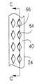
도 15는 본 발명의 실시형태에 따른, 도 14의 C-C선을 취하여 본 외과용 클립의 내면 상에 배열된 다이아몬드 형상 페이스가 십자형으로 정렬한 도이다.FIG. 15 is a cross-sectional view of diamond-like faces arranged on the inner surface of the present surgical clip, taken along line C-C of FIG. 14, according to an embodiment of the invention.
도 16은 본 발명의 제8실시예에 따른, 외과용 클립의 내면 상에 배열된 다이아몬드 형상 디프레션 페이스의 정렬을 도시한 평면도이다.16 is a plan view illustrating the alignment of a diamond shaped depression face arranged on the inner surface of a surgical clip, according to an eighth embodiment of the present invention.
도 17은 본 발명의 실시형태에 따른, 도 16의 D-D선을 취하여 본 외과용 클립의 내면 상에 배열된 다이아몬드 형상 페이스의 정렬을 도시한 도이다.FIG. 17 is a diagram illustrating the alignment of a diamond shaped face arranged on the inner surface of the surgical clip taken along line D-D of FIG. 16, according to an embodiment of the invention.
도 18은 본 발명의 실시형태에 따른, 외과용 클립을 형성하는 와이어의 사이드부 주변에 적어도 일 부분에 뻗어있는 널 패턴을 도시하는 외과용 클립의 레그 상의 널 패턴을 도시한 사시도이다.18 is a perspective view illustrating a null pattern on a leg of a surgical clip showing a null pattern extending at least in part around a side portion of a wire forming a surgical clip, in accordance with an embodiment of the present invention.
관련 출원 참조 문헌Related application references
본 출원은 2004년 6월 2일자에 출원된 미국 가출원 번호 제 60/576,332호의 이익을 청구하며, 상기 가출원의 명세서는 특히 전체로서 참조하여 병합된다.This application claims the benefit of US Provisional Application No. 60 / 56,3,32, filed June 2, 2000, the disclosure of which is specifically incorporated by reference in its entirety.
본 발명은 일반적으로 신체 조직을 고정(secure)하기 위한 외과용 결찰 클립(surgical ligation clip)에 관한 것이며, 상기 외과용 결찰 클립은 강화된 그립핑 특성을 가지고 있다. 2004년 6월 1일자에 출원된 미국특허출원번호 제29/206,622호의 명세서는 특히 전체로서 참조하여 병합된다.FIELD OF THE INVENTION The present invention generally relates to surgical ligation clips for securing body tissues, wherein the surgical ligation clips have enhanced gripping properties. The specification of US patent application Ser. No. 20 / 2012,622, filed June 1, 2000, is specifically incorporated by reference in its entirety.
외과용 클립은, 조직을 서로 봉합(bine)하는, 예컨대 신체 조직을 적절한 시간 동안 클로우즈(close)하거나 홀드(hold)하는 수술 절차에 사용된다.Surgical clips are used in surgical procedures that bind tissue together, such as closing or holding body tissue for a suitable time.
외과용 클립은 제자리에 위치하고 있어야, 바람직하지 못한 방식으로 이동하거나 떨어지지 않지, 그렇지 않으면 느슨해진다. 오늘날 사용되는 현존 외과용 클립들은 어느 정도의 마찰을 일으켜 신체 조직을 고정하는 세레이션(serration) 또는 인덴테이션(indentation)을 가지고 있다. 현존 외과용 클립은 공교롭게도 느슨해서, 신체 조직에 있어 불안정하다고 공지되어 있다. 물론, 이러한 유형의 일은 환자에게 치명적인 결과를 초래할 수 있다.Surgical clips must be in place so that they do not move or fall in undesired ways, otherwise they will loosen. Existing surgical clips used today have serrations or indentations that cause some friction to fix body tissue. Existing surgical clips are known to be loose and unstable in body tissue. Of course, this type of work can have fatal consequences for the patient.
그러므로, 외과용 클립의 적어도 일부에 강화된 그립핑 면을 갖는 외과용 클립을 제공함으로써, 종래의 단점을 극복할 수 있는 외과용 클립을 제공하는 것이 바람직하다.Therefore, it is desirable to provide a surgical clip that can overcome conventional drawbacks by providing a surgical clip having an enhanced gripping surface on at least a portion of the surgical clip.
본 발명은 클립, 예를 들면 신체 조직을 홀드하고 고정하는데 사용되는 외과용 클립에 특징이 있다. 상기 외과용 클립은, 조직의 추가적인 맞물림을 제공하기 위해, 상기 외과용 클립의 적어도 일부 내면 상에 강화된 그립핑 면을 갖는다.The invention is characterized by a clip, for example a surgical clip used to hold and secure body tissue. The surgical clip has a reinforced gripping surface on at least some inner surface of the surgical clip to provide additional engagement of the tissue.
본 발명의 일 특징에 따르면, 클립은 그립핑 면을 제공하고, 이 클립은 일반적으로 U자 형상이고, 일반적으로 V자 형상의 브리지 부재와 한 쌍의 레그 부재를 가지며, 각 레그 부재는 상기 일반적으로 V자형상의 브리지 부재의 대향 엔드로부터 뻗어있고, 상기 한 쌍의 레그 부재의 적어도 일부 내면과 상기 브리지 부재의 적어도 일부 내면에는 대각선 널(knurled) 패턴을 갖는다. 상기 널 패턴은 복수의 십자형 홈을 포함한다. 상기 널 패턴은 상기 레그의 적어도 일부 측벽 상에 형성된다. 상기 널 패턴은 복수의 돌기(protuberance) 및/또는 인덴테이션(indentation)으로부터 형성될 수 있다. 게다가, 상기 널 패턴은 복수의 다이아몬드 형상의 홈을 형성하는 복수의 홈을 포함할 수 있고, 상기 다이아몬드 형상의 홈 각각은 장축과 단축을 갖는다. 상기 다이아몬드 형상의 홈의 단축은 상기 레그 부재의 종축과 평행하거나, 상기 다이아몬드 형상의 홈의 장축은 상기 레그 부재의 종축과 평행하다. 여하튼, 상기 다이아몬드 형상의 홈은 인덴테이션으로 형성되거 나, 상기 다이아몬드 형상은 돌기일 수 있다.According to one feature of the invention, the clip provides a gripping surface, which clip is generally U-shaped, generally having a U-shaped bridge member and a pair of leg members, each leg member having said general And extending from opposite ends of the U-shaped bridge member, the at least some inner surface of the pair of leg members and the at least some inner surface of the bridge member having a diagonal knurled pattern. The null pattern includes a plurality of cross grooves. The null pattern is formed on at least some sidewall of the leg. The null pattern may be formed from a plurality of protuberances and / or indentations. In addition, the null pattern may include a plurality of grooves forming a plurality of diamond-shaped grooves, each of the diamond-shaped grooves having a long axis and a short axis. The short axis of the diamond-shaped groove is parallel to the longitudinal axis of the leg member, or the long axis of the diamond-shaped groove is parallel to the longitudinal axis of the leg member. In any case, the diamond-shaped groove may be formed by indentation, or the diamond-shaped groove may be a protrusion.
본 발명의 다른 특징은, 2개의 엔드를 갖는 연결부재와, 상기 연결부재의 각 엔드로부터 뻗어있는 한 쌍의 레그와, 상기 연결부재와 상기 한 쌍의 레그 중 적어도 하나의 내면의 적어도 일부에 형성되는 복수의 일반적인 다이아몬드 형상의 패턴을 포함하는 외과용 클립을 제공하는 것이다. 상기 복수의 일반적으로 다이아몬드 형상의 패턴은 리세스(recess) 또는 융기(raise)일 수 있다. 상기 복수의 일반적으로 다이아몬드 형상의 패턴은 상기 연결부재와 상기 한 쌍의 레그의 전체 내면 상에 형성될 수 있다. 게다가, 상기 복수의 일반적으로 다이아몬드 형상의 패턴은 상기 레그의 적어도 일부의 측벽 상에 형성될 수 있다. 또한, 상기 복수의 일반적으로 다이아몬드 형상의 패턴 각각은 장축과 단축을 갖는다. 상기 복수의 일반적으로 다이아몬드 형상의 패턴의 단축은 상기 레그의 종축과 평행하고 및/또는 상기 복수의 일반적으로 다이아몬드 형상의 패턴의 장축은 상기 레그의 종축과 평행하다. 또한, 상기 연결부재는 일반적으로 V자 형상일 수 있다. 또한, 상기 일반적으로 다이아몬드 형상의 패턴은 일반적으로 수직한 대각 홈으로 형성될 수 있다.Another feature of the invention is formed on at least part of an inner surface of at least one of a connecting member having two ends, a pair of legs extending from each end of the connecting member, and at least one of the connecting member and the pair of legs. It is to provide a surgical clip comprising a plurality of general diamond-shaped pattern. The plurality of generally diamond-shaped patterns may be recesses or rises. The plurality of generally diamond-shaped patterns may be formed on the entire inner surface of the connecting member and the pair of legs. In addition, the plurality of generally diamond shaped patterns may be formed on sidewalls of at least a portion of the leg. Further, each of the plurality of generally diamond-shaped patterns has a long axis and a short axis. The short axis of the plurality of generally diamond-shaped patterns is parallel to the longitudinal axis of the leg and / or the long axis of the plurality of generally diamond-shaped patterns is parallel to the longitudinal axis of the leg. In addition, the connecting member may be generally U-shaped. In addition, the generally diamond-shaped pattern may be formed in a generally vertical diagonal groove.
본 발명의 또 다른 특징에 따르면, 2개의 엔드를 갖는 연결부재와, 상기 연결부재의 각 엔드로부터 뻗어있는 한 쌍의 레그와, 상기 연결부재와 상기 한 쌍의 레그 중 적어도 하나의 내면 일부에 형성되는 복수의 교차 홈을 포함하는 외과용 클립이 제공된다. 상기 복수의 교차 홈은 일반적으로 수직하다.According to still another feature of the present invention, a connecting member having two ends, a pair of legs extending from each end of the connecting member, and a portion of an inner surface of at least one of the connecting member and the pair of legs are formed. A surgical clip is provided that includes a plurality of intersecting grooves. The plurality of intersecting grooves is generally vertical.
본 발명의 다른 예시적 실시예와 장점은 본 명세서와 첨부한 도면을 참조함으로서 확인될 수 있다.Other exemplary embodiments and advantages of the invention may be identified by reference to the specification and the accompanying drawings.
본 발명은 본 발명의 어떤 실시예의 비-제한 예에 의해 중요한 복수의 도면을 참조하여 더욱 상세히 기재되고, 몇 개의 도면을 통해 같은 도면부호는 같은 요소를 나타낸다.The invention is described in more detail with reference to a plurality of figures, which are important by means of non-limiting examples of certain embodiments of the invention, wherein like reference numerals designate like elements throughout the several views.
여기에 기재된 명세서는 본 발명의 실시예의 예로서 그리고 예시적 토론의 목적만을 위해서이고, 본 발명의 원리와 개념적 실시형태의 가장 유용하고 쉽게 이해되는 기술이라는 사실을 제공하기 위하여 제시된다. 이 점에서, 본 발명의 기본적 이해에 필요한 것보다 더 상세히 본 발명의 구조적 상세한 설명을 보여주기 위한 시도가 더 이상 이루어지지 않고, 상기 기술은 당업자가 본 발명의 형태가 실제로 어떻게 구현되지 명백히 하는 도면을 취하고 있다.The specification set forth herein is presented as an example of an embodiment of the invention and for the purpose of illustrative discussion only, and to provide the fact that it is the most useful and easily understood technique of the principles and conceptual embodiments of the invention. In this regard, no further attempts are made to show structural details of the invention in more detail than is necessary for a basic understanding of the invention, and the above description is a diagram for a person skilled in the art to clarify how the form of the invention is actually implemented. Is taking.
본 발명은, 신체의 내장 기관뿐 아니라 지방 조직, 근육, 근막(fascia)에 구현되는, 혈관, 림프관 및 이들 조합과 같은 신체 조직의 혈관폐색(occlusion) 또는 결찰(ligation)에 사용되는 외과용 클립에 관한 것이다. 이 외과용 클립은, 복강경 수술과 같은 보다 개선된 외과 수술뿐 아니라, 종래의 외과 수술에 사용하는데 적합하다.The present invention is a surgical clip used for occlusion or ligation of body tissues such as blood vessels, lymphatic vessels, and combinations thereof, which are implemented not only in the internal organs of the body but also in adipose tissue, muscle, fascia. It is about. This surgical clip is suitable for use in conventional surgical procedures as well as more advanced surgical procedures such as laparoscopic surgery.
도 1은 본 발명의 제1실시예에 따른 외과용 클립을 도시한 사시도이다. 외과용 클립(20)은, 위에서 기술된 다양한 조직은 포함하지만 한정되지 않는 신체 조직“T”를 홀딩 및 고정하기 위해 제공된다. 본 발명의 전형적인 외과용 클립은, 그 길이가 특정한 어플리케이션에 따라, 다른 길이도 가능하지만, 대략 1/4㎝ 내지 1/2㎝ 이다.1 is a perspective view showing a surgical clip according to a first embodiment of the present invention.
도 2는 본 발명의 실시형태에 따른 도 1에 도시한 외과용 클립의 평면도이 다. 도 1 및 도 2를 참조하면, 외과용 클립(20)은 한 쌍의 레그(24 및 26)를 갖는 통상 U자형 와이어(22)로 형성되며, 각 레그(24 및 26)는 통상 V자형 브리지(즉, 연결)부(32)의 일단으로부터 연장된다. 따라서, 외과용 클립(20)의 일단은 개방되고, 타단은 브리지부(32)에 의해 폐쇄 즉 연결되어 있다.2 is a plan view of the surgical clip shown in FIG. 1 in accordance with an embodiment of the present invention. 1 and 2, the
레그(24 및 26)를 형성하는 와이어(22)의 단면은 예컨대 도 1, 도 3 및 도 4에 도시한 바와 같이 일반적으로 직사각형이고, 약간 둥근 상면과 하면을 갖는다. 그러나, 주목할 점은, 임의의 적당한 단면 형상이 본 발명의 사상 내에서 사용될 수 있다는 것이다. 이 점에 있어서는, 와이어의 용어가 사용되지만, 임의의 적당한 스톡(stock)이 사용될 수 있음은 물론이다. 더욱이, 외과용 클립(20)은, 금속, 복합물, 플라스틱, 수지 재질, 및/또는 합성물을 포함하지만 한정되지 않는 임의의 적당한 재질, 또는 재질의 조합으로 형성될 수 있음은 알 수 있다.The cross section of the
외과용 클립(20)을 형성하는 와이어(22)는 도 1에 도시한 바와 같이, 종축“L”를 갖는다. 일 실시예에 있어서, 외과용 클립의 안쪽 정면(40)에는, 도 1, 도 3 및 도 5의 예에서 도시한 바와 같이, 제1복수의 일정 간격 떨어진 대각선으로 배열된 홈, 범프(bumps) 또는 컷(cuts)(44)이 있는 표면을 갖는다. 내면(40)은 또한 제2복수의 일정 간격 떨어진 대각선으로 배열된 홈, 범프 또는 컷(45)을 가지며, 이것은 일반적으로, 제1복수의 대각선으로 배열된 홈(44)과 수직하다. 결과적으로, 내면(40) 상에 형성된 제1 및 제2복수의 대각선으로 배열된 홈(44 및 45)은 일련의 교차형 홈으로 이루어지고, 동시에 외과용 클립(20)의 내면(40) 상에 통상의 다이아몬드와 같은 패턴, 예컨대 도 8 및 도 9에 도시한 바와 같은 조직-맞물림면 (tissue-engaging surface)(46)를 형성한다.The
대각선 교차형 홈은 외과용 클립(20)의 내면(40)에 의해 조직의 복수 그립핑 각도를 제공한다. 다이아몬드-형태의 조직-맞물림면(46)은, 조직“T”에서 외과용 클립(20)으로 우수한 조직 맞물림을 위해, 대향되는 코너에 예각을 제공하고, 교대하는 대향 코너에 둔각을 제공한다. 결과적으로, 외과용 클립(20) 내에서 조직“T”의 이동 또는 미끄러짐은 최소화된다.The diagonal cross grooves provide a plurality of gripping angles of tissue by the
도 3은 도 2의 A-A선을 따라 취하여 본 외과용 클립의 단면도이다. 외과용 클립(20)의 내면(40) 상에, 제1복수의 일정 간격 떨어진 대각선으로 배열된 홈(44)은 제2복수의 일정 간격 떨어진 대각선으로 배열된 홈(45)과 일반적으로 수직하다. 도시된 바와 같이, 브리지 부재(32)의 내면(40)에는 또한 복수의 홈이 제공된다.3 is a cross-sectional view of the surgical clip taken along line A-A of FIG. On the
도 4는 도 1에 도시된 외과용 클립의 평면도이다. 브리지 부재(32)와 레그(26)의 외면에는 본 실시예에서 임의의 홈 없이 도시되어 있다. 그러나, 선택적인 실시예에 있어서, 예컨대, 브리지 부재 및 레그의 외면 중 적어도 하나에 도 3에 도시한 바와 같은 유사한 패턴의 홈을 제공하는 것은 가능하다.4 is a plan view of the surgical clip shown in FIG. The outer surfaces of the
도 5는 도 2의 B-B선을 따라 취하여 본 외과용 클립의 도면이다. 외과용 클립(20)의 내면(40) 상에, 제1복수의 일정 간격 떨어진 대각선으로 배열된 홈(44)은 제2복수의 일정 간격 떨어진 대각선으로 배열된 홈(45)과 일반적으로 수직하다. 도시된 바와 같이, 레그(24)와 레그(26) 사이의 브리지 부재(32)의 내면(40)에는 또한 복수의 홈이 제공된다.5 is a view of the surgical clip taken along line B-B of FIG. On the
도 6은 도 1에 도시된 바와 같이 외과용 클립의 저면도이다. 도시된 바와 같 이, 브리지 부재(32)는 둥근 에지와 코너를 갖는 일반적으로 직사각형이다.6 is a bottom view of the surgical clip as shown in FIG. 1. As shown, the
도 7은 강화된 조직 맞물림면이 클립의 내면의 일부에만 제공된 외과용 클립의 사시도이다. 도시된 바와 같이, 강화된 조직 맞물림면은 외과용 클립(20)의 전체 내면(40)에 뻗어 있지 않다. 이 실시예에 있어서, 강화된 조직-맞물림면은 외과용 클립(20)의 양쪽 레그(24, 26)의 내면과, 브리지 부재(32) 내면의 일부를 따라 뻗어있다. 도 7에 관해 기술된 일부분 강화 조직 맞물림면은 임의의 다른 배치 및/또는 여기서 기술된 패턴으로 사용될 수 있다. 다른 선택적 실시예에 있어서, 강화 조직 맞물림면은, 반복적인 스타트 및 스톱 패턴으로, 외과용 클립(20)의 전체 내면(40)을 따라 불연속 단속적 방식으로 뻗어 있을 수 있다. 또 다른 실시예에 있어서, 조직-맞물림면은 레그(24 및 26)의 끝까지 뻗어있지 않을 수 있다.7 is a perspective view of a surgical clip in which a reinforced tissue engagement surface is provided only to a portion of the inner surface of the clip. As shown, the reinforced tissue engaging surface does not extend to the entire
도 8은 본 발명의 제2실시예에 따른, 널(knurl)을 갖는 외과용 클립의 레그 단면의 사시도이다. 도시된 바와 같이, 레그(24)는 일반적으로 다이아몬드와 같은 패턴의 조직 맞물림면(46)을 포함하며, 이 조직 맞물림면은 외과용 클립의 내면 상에 형성된다. 그립핑 널과 유사한 조직 맞물림면은, 임의의 추가적인 조직 외상을 초래함이 없이, 추가적인 강도와 외과용 클립 고정성을 제공한다. 게다가, 평행과 수직의 비교 풀-오프(pull-off) 테스트를 통해, 일반적으로 다이아몬드와 같은 패턴의 조직 맞물림면(40)은 종래 외과용 클립 디자인에 비하여, 조직 표면에 손상을 주지 않고 전체적인 그립핑 및 맞물림(occlusion)의 힘을 향상시킨다는 사실을 증명하였다.8 is a perspective view of a leg cross section of a surgical clip with a knurl, in accordance with a second embodiment of the present invention. As shown,
도 9는 본 발명의 제3실시예에 따른, 외과용 클립의 레그 부분 상에 형성된 널 패턴의 사시도이다. 도시된 바와 같이, 다이아몬드와 같은 패턴의 조직 맞물림면(46)은 도 8의 다이아몬드와 같은 패턴의 조직 맞물림면보다 더 얕다. 더욱이, 도 9의 다이아몬드와 같은 패턴의 조직 맞물림면(46)은 도 8의 다이아몬드와 같은 패턴의 조직 맞물림면보다 더 넓은 페이스면(face surfaces)을 포함한다. 여하튼, 본 발명의 사상에서 벗어남이 없이 다이아몬드와 같은 패턴의 조직 맞물림면의 정확한 형상으로 변형될 수 있다.9 is a perspective view of a null pattern formed on the leg portion of a surgical clip, in accordance with a third embodiment of the present invention. As shown, the
도 10은 본 발명의 제4실시예에 따른, 외과용 클립의 널 부분의 평면도이다. 도시된 바와 같이, 강화 조직 맞물림면(46)은 장축(50)과 단축(52)을 갖는다. 장축(50)은 외과용 클립(20)을 형성하는 와이어(22)의 종축“L”에 일반적으로 평행하다.10 is a plan view of a null portion of a surgical clip, in accordance with a fourth embodiment of the present invention. As shown, the reinforcing
이러한 배열은 또한 도 11에 도시되어 있고, 이 도 11은 도 10에 도시된 외과용 클립의 면의 사시도이다. 강화 조직 맞물림면(46)은 장축(50)과 단축(52)을 갖는다. 장축(50)은 외과용 클립(20)을 형성하는 와이어(22)의 종축“L”에 일반적으로 평행하다.This arrangement is also shown in FIG. 11, which is a perspective view of the face of the surgical clip shown in FIG. 10. The reinforcing
도 12는 본 발명의 제5실시예에 따른, 외과용 클립의 레그 일부분의 사시도이다. 도시된 바와 같이, 레그(24)의 내면 상의 강화 조직 맞물림면(46)은 외과용 클립(20)의 와이어(22)의 종축“L”에 대해 횡으로 걸치는 장축(50)을 갖는다.12 is a perspective view of a leg portion of a surgical clip, in accordance with a fifth embodiment of the present invention. As shown, the reinforcing
본 발명의 다른 실시예에 있어서, 일반적으로 다이아몬드 형상 면은 외과용 클립(20)의 이너 사이드(40)에 형성된 디프레션(depression) 또는 리세스(54) 내에 존재한다. 더욱이, 십자형 융기부(ridges)(56)는, 도 13 내지 도 17에 도시된 바와 같이, 위쪽을 향해 방사상으로 일정 간격 유지한 채 외과용 클립(20)의 다이아몬드 형상 면으로부터 위쪽으로 뻗어있다.In another embodiment of the present invention, the diamond-shaped face generally resides in a depression or
도 13은 본 발명의 제6실시예에 따른, 외과용 클립의 레그의 내면 상에 배열된 십자형 디프레션 어레인지먼트의 사시도이다. 도시된 바와 같이, 디프레션 또는 리세스(54) 내의 일반적으로 다이아몬드 형상 면이, 외과용 클립의 내면(40)에 형성되어 있다. 더욱이, 십자형 융기부(56)는, 외과용 클립(20)의 다이아몬드 형상 면으로부터 위쪽으로 뻗어있다.13 is a perspective view of a cruciform depression arrangement arranged on an inner surface of a leg of a surgical clip, according to a sixth embodiment of the present invention. As shown, generally diamond-shaped surfaces within depressions or recesses 54 are formed in the
도 14는 본 발명의 제7실시예에 따른, 외과용 클립의 이너 사이드 상에 배열된 다이아몬드 형상 페이스가 십자형으로 정렬한 평면도이다. 도시된 바와 같이, 외과용 클립의 이너 사이드 상에 배열된 다이아몬드 형상 페이스는, 이너 사이드(40)의 리세스(54) 내에 형성되어 있다. 도 15는 도 14의 C-C선을 취하여 본 외과용 클립의 내면 상에 배열된 다이아몬드 형상 페이스가 십자형으로 정렬한 도이다. 도시된 바와 같이, 리세스(54)와 십자형 융기부(56)가 결합하여, 추가적인 조직 맞물림 특성을 제공한다.14 is a plan view of a diamond-shaped face arranged on the inner side of a surgical clip crosswise aligned in accordance with a seventh embodiment of the present invention. As shown, a diamond shaped face arranged on the inner side of the surgical clip is formed in the
도 16은 본 발명의 제8실시예에 따른, 외과용 클립의 내면 상에 배열된 다이아몬드 형상 디프레션 페이스의 정렬을 도시한 평면도이다. 도시된 바와 같이, 외과용 클립의 이너 사이드 상에 배열된 다이아몬드 형상 페이스는, 리세스(54) 내에 형성되어 있지만, 리세스(54)는 서로 엇갈린 방식으로 배열되어 있다. 도 17은 도 16의 D-D선을 취하여 본 외과용 클립의 내면 상에 배열된 다이아몬드 형상 페이스의 정렬을 도시한 도이다. 따라서, 본 발명에 의하면, 여기서 기술된 다이아몬드 형상 패턴의 특정 어레인지먼트는 균일한 열, 엇갈림, 또는 임의의 다른 적당한 어레인지먼트로 배열될 수 있다.16 is a plan view illustrating the alignment of a diamond shaped depression face arranged on the inner surface of a surgical clip, according to an eighth embodiment of the present invention. As shown, the diamond shaped faces arranged on the inner side of the surgical clip are formed in the
도 18은 본 발명의 실시형태에 따른, 외과용 클립을 형성하는 와이어의 사이드부 주위에 적어도 일 부분에 뻗어있는 널 패턴을 도시하는 외과용 클립의 레그 상의 널 패턴을 도시한 사시도이다. 도시된 바와 같이, 강화 조직 맞물림면(60)은 외과용 클립(20)을 형성하는 와이어(65)의 사이드부(62) 주위에 적어도 일부분에 뻗었다. 사이드부(62)에는 널이나 홈이 형성되거나 내면(40)으로 취급되고, 이것은 조직에 더 맞물리고, 관련 조직 미끄러짐의 가능성을 더 최소화시킬 수 있다. 바꾸어 말하면, 임의의 전술한 실시예 및/또는 실시형태는 도 18에 도시된 구성이 사용될 수 있다.18 is a perspective view illustrating a null pattern on a leg of a surgical clip showing a null pattern extending at least in part around a side portion of a wire forming a surgical clip, in accordance with an embodiment of the present invention. As shown, the reinforcing
실시예에서 더 긴 제1축과 더 짧은 제2축을 갖는 다이아몬드 형상을 구비한 대각선으로 배열된 디프레션, 범프 또는 돌기(protuberances)의 어레인지먼트는, 외과용 클립(20)이 제거된다면, 조직으로부터 개선된 수직한 풀-오프를 허용한다. 십자형 디자인은 또한 외과용 클립(20)이 제거된다면, 외과용 클립(20)의 더 낳은 평행한 풀-오프를 제공하고, 외과용 클립(20)에 의해 봉합된 조직의 우수한 맞물림을 제공한다.In an embodiment the arrangement of diagonally arranged depressions, bumps or protuberances with a diamond shape having a longer first axis and a shorter second axis is improved from the tissue if the
비록, 본 발명은 예시적 실시예를 참고하여 기술되었지만, 사용되어진 용어는 제한적이라기 보다는 오히려 기술 및 예증의 용어임은 자명하다 할 것이다. 본 실시형태에서 본 발명의 사상과 범주를 벗어남이 없이, 첨부한 청구항의 범위 내에 서, 현재와 같이 수정하여 변형이 이루어질 수 있다. 비록 본 발명이 특정한 수단, 재질 및 실시예를 참조하여 여기에 기술되었지만, 본 발명은 여기서 기술된 명세서에 제한되게 의도된 것은 아니다. 대신에, 본 발명은, 첨부한 청구항의 범주 내에서와 같이, 기능적으로 균등한 구조, 방법 및 용도 모두에 미친다.Although the invention has been described with reference to exemplary embodiments, it is to be understood that the terminology which has been used is intended to be in the nature of words of description and illustration rather than of limitation. In the present embodiment, modifications may be made without departing from the spirit and scope of the present invention, as modified by the present invention, within the scope of the appended claims. Although the present invention has been described herein with reference to specific means, materials and embodiments, the present invention is not intended to be limited to the description herein. Instead, the invention extends to all functionally equivalent structures, methods and uses, as are within the scope of the appended claims.
Claims (25)
Translated fromKoreanApplications Claiming Priority (4)
| Application Number | Priority Date | Filing Date | Title |
|---|---|---|---|
| US57633204P | 2004-06-02 | 2004-06-02 | |
| US60/576,332 | 2004-06-02 | ||
| US11/088,752US20050273122A1 (en) | 2004-06-02 | 2005-03-25 | Clip with enhanced gripping arrangement |
| US11/088,752 | 2005-03-25 |
Publications (2)
| Publication Number | Publication Date |
|---|---|
| KR20060092798Atrue KR20060092798A (en) | 2006-08-23 |
| KR100703962B1 KR100703962B1 (en) | 2007-04-04 |
Family
ID=34936998
Family Applications (1)
| Application Number | Title | Priority Date | Filing Date |
|---|---|---|---|
| KR1020050043488AExpired - Fee RelatedKR100703962B1 (en) | 2004-06-02 | 2005-05-24 | Clip with reinforced gripping arrangement |
Country Status (4)
| Country | Link |
|---|---|
| US (1) | US20050273122A1 (en) |
| EP (1) | EP1602335A1 (en) |
| JP (1) | JP2005342521A (en) |
| KR (1) | KR100703962B1 (en) |
Cited By (1)
| Publication number | Priority date | Publication date | Assignee | Title |
|---|---|---|---|---|
| KR20220063493A (en)* | 2020-11-10 | 2022-05-17 | 이승원 | Surgical clip |
Families Citing this family (117)
| Publication number | Priority date | Publication date | Assignee | Title |
|---|---|---|---|---|
| EP1608272B1 (en) | 2003-03-11 | 2017-01-25 | Covidien LP | Clip applying apparatus with angled jaw |
| US7819886B2 (en) | 2004-10-08 | 2010-10-26 | Tyco Healthcare Group Lp | Endoscopic surgical clip applier |
| US8409222B2 (en) | 2004-10-08 | 2013-04-02 | Covidien Lp | Endoscopic surgical clip applier |
| US9763668B2 (en) | 2004-10-08 | 2017-09-19 | Covidien Lp | Endoscopic surgical clip applier |
| EP2641548B1 (en) | 2004-10-08 | 2015-08-19 | Covidien LP | Endoscopic surgical clip applier |
| CA2809110A1 (en) | 2004-10-08 | 2006-04-20 | Tyco Healthcare Group Lp | Apparatus for applying surgical clips |
| US9326776B2 (en) | 2005-09-29 | 2016-05-03 | Applied Medical Resources Corporation | Manually actuated surgical clip applier |
| US20070173866A1 (en) | 2006-01-23 | 2007-07-26 | Tyco Healthcare Group, Lp | Surgical hemostatic clip |
| EP2015681B1 (en) | 2006-05-03 | 2018-03-28 | Datascope Corp. | Tissue closure device |
| CA2605135C (en) | 2006-10-17 | 2014-12-30 | Tyco Healthcare Group Lp | Apparatus for applying surgical clips |
| EP2157920B1 (en) | 2007-03-26 | 2017-09-27 | Covidien LP | Endoscopic surgical clip applier |
| CN102327136B (en) | 2007-04-11 | 2014-04-23 | 柯惠Lp公司 | Surgical clip applier |
| US20090187198A1 (en)* | 2008-01-22 | 2009-07-23 | Barry Weitzner | Resolution Clip |
| US8465502B2 (en) | 2008-08-25 | 2013-06-18 | Covidien Lp | Surgical clip applier and method of assembly |
| US20110208212A1 (en) | 2010-02-19 | 2011-08-25 | Zergiebel Earl M | Surgical clip applier |
| US8056565B2 (en) | 2008-08-25 | 2011-11-15 | Tyco Healthcare Group Lp | Surgical clip applier and method of assembly |
| US8409223B2 (en) | 2008-08-29 | 2013-04-02 | Covidien Lp | Endoscopic surgical clip applier with clip retention |
| US8585717B2 (en) | 2008-08-29 | 2013-11-19 | Covidien Lp | Single stroke endoscopic surgical clip applier |
| US8267944B2 (en) | 2008-08-29 | 2012-09-18 | Tyco Healthcare Group Lp | Endoscopic surgical clip applier with lock out |
| US9358015B2 (en) | 2008-08-29 | 2016-06-07 | Covidien Lp | Endoscopic surgical clip applier with wedge plate |
| US8734469B2 (en) | 2009-10-13 | 2014-05-27 | Covidien Lp | Suture clip applier |
| US9186136B2 (en) | 2009-12-09 | 2015-11-17 | Covidien Lp | Surgical clip applier |
| US8545486B2 (en) | 2009-12-15 | 2013-10-01 | Covidien Lp | Surgical clip applier |
| US8403945B2 (en) | 2010-02-25 | 2013-03-26 | Covidien Lp | Articulating endoscopic surgical clip applier |
| WO2011112877A1 (en)* | 2010-03-10 | 2011-09-15 | Menn Pavel | Surgical clips for laparoscopic procedures |
| US8968337B2 (en) | 2010-07-28 | 2015-03-03 | Covidien Lp | Articulating clip applier |
| US8403946B2 (en) | 2010-07-28 | 2013-03-26 | Covidien Lp | Articulating clip applier cartridge |
| US9011464B2 (en) | 2010-11-02 | 2015-04-21 | Covidien Lp | Self-centering clip and jaw |
| US9186153B2 (en) | 2011-01-31 | 2015-11-17 | Covidien Lp | Locking cam driver and jaw assembly for clip applier |
| USD769445S1 (en)* | 2011-03-10 | 2016-10-18 | Conmed Corporation | Surgical clip |
| US9775623B2 (en) | 2011-04-29 | 2017-10-03 | Covidien Lp | Surgical clip applier including clip relief feature |
| US8485853B2 (en)* | 2011-11-03 | 2013-07-16 | Delphi Technologies, Inc. | Electrical contact having knurl pattern with recessed rhombic elements that each have an axial minor distance |
| US8622774B2 (en) | 2011-11-07 | 2014-01-07 | Delphi Technologies, Inc. | Electrical contact having channel with angled sidewalls and romboid knurl pattern |
| US20130131697A1 (en) | 2011-11-21 | 2013-05-23 | Covidien Lp | Surgical clip applier |
| US9364239B2 (en) | 2011-12-19 | 2016-06-14 | Covidien Lp | Jaw closure mechanism for a surgical clip applier |
| US9364216B2 (en) | 2011-12-29 | 2016-06-14 | Covidien Lp | Surgical clip applier with integrated clip counter |
| US9408610B2 (en) | 2012-05-04 | 2016-08-09 | Covidien Lp | Surgical clip applier with dissector |
| US9532787B2 (en) | 2012-05-31 | 2017-01-03 | Covidien Lp | Endoscopic clip applier |
| CN103006288B (en)* | 2012-12-19 | 2014-06-18 | 杭州铭众生物科技有限公司 | V-shaped vessel ligature clamp with single-layer structure and method for preparing V-shaped vessel ligature clamp |
| US9968362B2 (en) | 2013-01-08 | 2018-05-15 | Covidien Lp | Surgical clip applier |
| US9113892B2 (en) | 2013-01-08 | 2015-08-25 | Covidien Lp | Surgical clip applier |
| US9750500B2 (en) | 2013-01-18 | 2017-09-05 | Covidien Lp | Surgical clip applier |
| US9775624B2 (en) | 2013-08-27 | 2017-10-03 | Covidien Lp | Surgical clip applier |
| WO2015077356A1 (en) | 2013-11-19 | 2015-05-28 | Wheeler William K | Fastener applicator with interlock |
| US10702278B2 (en) | 2014-12-02 | 2020-07-07 | Covidien Lp | Laparoscopic surgical ligation clip applier |
| US9931124B2 (en) | 2015-01-07 | 2018-04-03 | Covidien Lp | Reposable clip applier |
| CN107205747B (en) | 2015-01-15 | 2020-09-08 | 柯惠有限合伙公司 | Reusable endoscopic surgical clip applier |
| US10292712B2 (en) | 2015-01-28 | 2019-05-21 | Covidien Lp | Surgical clip applier with integrated cutter |
| US10159491B2 (en) | 2015-03-10 | 2018-12-25 | Covidien Lp | Endoscopic reposable surgical clip applier |
| CN108348259B (en) | 2015-11-03 | 2020-12-11 | 柯惠有限合伙公司 | Endoscopic Surgical Fixture Applicator |
| US10390831B2 (en) | 2015-11-10 | 2019-08-27 | Covidien Lp | Endoscopic reposable surgical clip applier |
| US10905425B2 (en) | 2015-11-10 | 2021-02-02 | Covidien Lp | Endoscopic reposable surgical clip applier |
| US10702280B2 (en) | 2015-11-10 | 2020-07-07 | Covidien Lp | Endoscopic reposable surgical clip applier |
| CN108472044B (en) | 2016-01-11 | 2021-04-16 | 柯惠有限合伙公司 | endoscope-reserved surgical clip applier |
| AU2016388454A1 (en) | 2016-01-18 | 2018-07-19 | Covidien Lp | Endoscopic surgical clip applier |
| CA2958160A1 (en) | 2016-02-24 | 2017-08-24 | Covidien Lp | Endoscopic reposable surgical clip applier |
| WO2018027788A1 (en) | 2016-08-11 | 2018-02-15 | Covidien Lp | Endoscopic surgical clip applier and clip applying systems |
| CN109640844B (en) | 2016-08-25 | 2021-08-06 | 柯惠Lp公司 | Endoscopic Surgical Clip Appliers and Applicator Systems |
| US10660651B2 (en) | 2016-10-31 | 2020-05-26 | Covidien Lp | Endoscopic reposable surgical clip applier |
| US10639044B2 (en) | 2016-10-31 | 2020-05-05 | Covidien Lp | Ligation clip module and clip applier |
| US10426489B2 (en) | 2016-11-01 | 2019-10-01 | Covidien Lp | Endoscopic reposable surgical clip applier |
| US10610236B2 (en) | 2016-11-01 | 2020-04-07 | Covidien Lp | Endoscopic reposable surgical clip applier |
| US10492795B2 (en) | 2016-11-01 | 2019-12-03 | Covidien Lp | Endoscopic surgical clip applier |
| US10709455B2 (en) | 2017-02-02 | 2020-07-14 | Covidien Lp | Endoscopic surgical clip applier |
| US10201353B2 (en)* | 2017-02-03 | 2019-02-12 | Pavel Menn | Ligation clip |
| US11116514B2 (en) | 2017-02-06 | 2021-09-14 | Covidien Lp | Surgical clip applier with user feedback feature |
| US10758244B2 (en) | 2017-02-06 | 2020-09-01 | Covidien Lp | Endoscopic surgical clip applier |
| US10660725B2 (en) | 2017-02-14 | 2020-05-26 | Covidien Lp | Endoscopic surgical clip applier including counter assembly |
| US10603038B2 (en) | 2017-02-22 | 2020-03-31 | Covidien Lp | Surgical clip applier including inserts for jaw assembly |
| US11583291B2 (en) | 2017-02-23 | 2023-02-21 | Covidien Lp | Endoscopic surgical clip applier |
| US10548602B2 (en) | 2017-02-23 | 2020-02-04 | Covidien Lp | Endoscopic surgical clip applier |
| US10675043B2 (en) | 2017-05-04 | 2020-06-09 | Covidien Lp | Reposable multi-fire surgical clip applier |
| US10722235B2 (en) | 2017-05-11 | 2020-07-28 | Covidien Lp | Spring-release surgical clip |
| CA3068282C (en) | 2017-06-22 | 2022-06-28 | Teleflex Medical Incorporated | Surgical clip |
| US10639032B2 (en) | 2017-06-30 | 2020-05-05 | Covidien Lp | Endoscopic surgical clip applier including counter assembly |
| US10660723B2 (en) | 2017-06-30 | 2020-05-26 | Covidien Lp | Endoscopic reposable surgical clip applier |
| US10675112B2 (en) | 2017-08-07 | 2020-06-09 | Covidien Lp | Endoscopic surgical clip applier including counter assembly |
| US10863992B2 (en) | 2017-08-08 | 2020-12-15 | Covidien Lp | Endoscopic surgical clip applier |
| US10932790B2 (en) | 2017-08-08 | 2021-03-02 | Covidien Lp | Geared actuation mechanism and surgical clip applier including the same |
| US10786262B2 (en) | 2017-08-09 | 2020-09-29 | Covidien Lp | Endoscopic reposable surgical clip applier |
| US10786263B2 (en) | 2017-08-15 | 2020-09-29 | Covidien Lp | Endoscopic reposable surgical clip applier |
| US10835341B2 (en) | 2017-09-12 | 2020-11-17 | Covidien Lp | Endoscopic surgical clip applier and handle assemblies for use therewith |
| US10835260B2 (en) | 2017-09-13 | 2020-11-17 | Covidien Lp | Endoscopic surgical clip applier and handle assemblies for use therewith |
| US10653429B2 (en) | 2017-09-13 | 2020-05-19 | Covidien Lp | Endoscopic surgical clip applier |
| US10758245B2 (en) | 2017-09-13 | 2020-09-01 | Covidien Lp | Clip counting mechanism for surgical clip applier |
| US11376015B2 (en) | 2017-11-03 | 2022-07-05 | Covidien Lp | Endoscopic surgical clip applier and handle assemblies for use therewith |
| US10828036B2 (en) | 2017-11-03 | 2020-11-10 | Covidien Lp | Endoscopic surgical clip applier and handle assemblies for use therewith |
| US10932791B2 (en) | 2017-11-03 | 2021-03-02 | Covidien Lp | Reposable multi-fire surgical clip applier |
| US10945734B2 (en) | 2017-11-03 | 2021-03-16 | Covidien Lp | Rotation knob assemblies and surgical instruments including the same |
| US11116513B2 (en) | 2017-11-03 | 2021-09-14 | Covidien Lp | Modular surgical clip cartridge |
| ES2981210T3 (en) | 2017-11-14 | 2024-10-07 | Teleflex Medical Inc | Surgical clip |
| US10722236B2 (en) | 2017-12-12 | 2020-07-28 | Covidien Lp | Endoscopic reposable surgical clip applier |
| US10743887B2 (en) | 2017-12-13 | 2020-08-18 | Covidien Lp | Reposable multi-fire surgical clip applier |
| US10849630B2 (en) | 2017-12-13 | 2020-12-01 | Covidien Lp | Reposable multi-fire surgical clip applier |
| US10959737B2 (en) | 2017-12-13 | 2021-03-30 | Covidien Lp | Reposable multi-fire surgical clip applier |
| US11051827B2 (en) | 2018-01-16 | 2021-07-06 | Covidien Lp | Endoscopic surgical instrument and handle assemblies for use therewith |
| JP7348199B2 (en) | 2018-03-28 | 2023-09-20 | データスコープ コーポレイション | Device for atrial appendage exclusion |
| US10993721B2 (en) | 2018-04-25 | 2021-05-04 | Covidien Lp | Surgical clip applier |
| US10786273B2 (en) | 2018-07-13 | 2020-09-29 | Covidien Lp | Rotation knob assemblies for handle assemblies |
| US10531883B1 (en) | 2018-07-20 | 2020-01-14 | Syntheon 2.0, LLC | Aspiration thrombectomy system and methods for thrombus removal with aspiration catheter |
| US11259887B2 (en) | 2018-08-10 | 2022-03-01 | Covidien Lp | Feedback mechanisms for handle assemblies |
| US11344316B2 (en) | 2018-08-13 | 2022-05-31 | Covidien Lp | Elongated assemblies for surgical clip appliers and surgical clip appliers incorporating the same |
| US11033256B2 (en) | 2018-08-13 | 2021-06-15 | Covidien Lp | Linkage assembly for reusable surgical handle assemblies |
| US11278267B2 (en) | 2018-08-13 | 2022-03-22 | Covidien Lp | Latch assemblies and surgical instruments including the same |
| US11219463B2 (en) | 2018-08-13 | 2022-01-11 | Covidien Lp | Bilateral spring for surgical instruments and surgical instruments including the same |
| US11246601B2 (en) | 2018-08-13 | 2022-02-15 | Covidien Lp | Elongated assemblies for surgical clip appliers and surgical clip appliers incorporating the same |
| US11253267B2 (en) | 2018-08-13 | 2022-02-22 | Covidien Lp | Friction reduction mechanisms for handle assemblies |
| US11051828B2 (en) | 2018-08-13 | 2021-07-06 | Covidien Lp | Rotation knob assemblies and surgical instruments including same |
| US11147566B2 (en) | 2018-10-01 | 2021-10-19 | Covidien Lp | Endoscopic surgical clip applier |
| KR102240609B1 (en) | 2018-12-04 | 2021-04-15 | 최교창 | surgical clip |
| US11524398B2 (en) | 2019-03-19 | 2022-12-13 | Covidien Lp | Gear drive mechanisms for surgical instruments |
| EP4076216A1 (en) | 2019-12-19 | 2022-10-26 | Teleflex Medical Incorporated | Surgical clip |
| US11779340B2 (en) | 2020-01-02 | 2023-10-10 | Covidien Lp | Ligation clip loading device |
| US11723669B2 (en) | 2020-01-08 | 2023-08-15 | Covidien Lp | Clip applier with clip cartridge interface |
| WO2021192168A1 (en)* | 2020-03-26 | 2021-09-30 | 日本ライフライン株式会社 | Catheter |
| US12114866B2 (en) | 2020-03-26 | 2024-10-15 | Covidien Lp | Interoperative clip loading device |
| US12419648B2 (en) | 2022-09-26 | 2025-09-23 | Covidien Lp | Two-part fasteners for surgical clip appliers and surgical clip appliers for deploying the same |
Family Cites Families (18)
| Publication number | Priority date | Publication date | Assignee | Title |
|---|---|---|---|---|
| US4242902A (en)* | 1978-05-11 | 1981-01-06 | United States Surgical Corporation | Surgical clip applicator |
| US4299224A (en)* | 1979-06-06 | 1981-11-10 | United States Surgical Corporation | Disposable clip applier |
| US4449530A (en)* | 1981-07-15 | 1984-05-22 | Ethicon, Inc. | Hemostatic clips and method of manufacture |
| US4509518A (en)* | 1982-02-17 | 1985-04-09 | United States Surgical Corporation | Apparatus for applying surgical clips |
| US4976722A (en)* | 1989-05-22 | 1990-12-11 | Ethicon, Inc. | Surgical hemostatic clips |
| US5984939A (en)* | 1989-12-05 | 1999-11-16 | Yoon; Inbae | Multifunctional grasping instrument with cutting member and operating channel for use in endoscopic and non-endoscopic procedures |
| US5171253A (en)* | 1991-03-22 | 1992-12-15 | Klieman Charles H | Velcro-like closure system with absorbable suture materials for absorbable hemostatic clips and surgical strips |
| US5201746A (en)* | 1991-10-16 | 1993-04-13 | United States Surgical Corporation | Surgical hemostatic clip |
| US5330442A (en)* | 1992-10-09 | 1994-07-19 | United States Surgical Corporation | Suture retaining clip |
| CA2120828C (en)* | 1993-04-16 | 1999-11-02 | Paul J. Phillips | Surgical hemostatic clip |
| US5620452A (en)* | 1994-12-22 | 1997-04-15 | Yoon; Inbae | Surgical clip with ductile tissue penetrating members |
| DE29509079U1 (en)* | 1995-06-01 | 1995-08-17 | Aesculap Ag, 78532 Tuttlingen | Surgical clip |
| US6077280A (en)* | 1995-06-29 | 2000-06-20 | Thomas Jefferson University | Surgical clamp |
| US6015417A (en)* | 1996-01-25 | 2000-01-18 | Reynolds, Jr.; Walker | Surgical fastener |
| DE19832739A1 (en)* | 1998-07-21 | 2000-02-03 | Aesculap Ag & Co Kg | Surgical clip in U or V form for clamping hollow organs e.g. arteries |
| US6165204A (en)* | 1999-06-11 | 2000-12-26 | Scion International, Inc. | Shaped suture clip, appliance and method therefor |
| US6610073B1 (en)* | 1999-10-19 | 2003-08-26 | Scion International, Inc. | Surgical clip, clip applicator and method therefor |
| US6695854B1 (en)* | 1999-11-29 | 2004-02-24 | General Surgical Innovations, Inc. | Blood vessel clip and applicator |
- 2005
- 2005-03-25USUS11/088,752patent/US20050273122A1/ennot_activeAbandoned
- 2005-05-24KRKR1020050043488Apatent/KR100703962B1/ennot_activeExpired - Fee Related
- 2005-05-27EPEP05011488Apatent/EP1602335A1/ennot_activeWithdrawn
- 2005-06-02JPJP2005162545Apatent/JP2005342521A/enactivePending
Cited By (1)
| Publication number | Priority date | Publication date | Assignee | Title |
|---|---|---|---|---|
| KR20220063493A (en)* | 2020-11-10 | 2022-05-17 | 이승원 | Surgical clip |
Also Published As
| Publication number | Publication date |
|---|---|
| KR100703962B1 (en) | 2007-04-04 |
| EP1602335A1 (en) | 2005-12-07 |
| US20050273122A1 (en) | 2005-12-08 |
| JP2005342521A (en) | 2005-12-15 |
Similar Documents
| Publication | Publication Date | Title |
|---|---|---|
| KR100703962B1 (en) | Clip with reinforced gripping arrangement | |
| CN107708580B (en) | Anti-migration surgical ligation clip | |
| US7695472B2 (en) | Locking bone plate | |
| US5201746A (en) | Surgical hemostatic clip | |
| JP4979972B2 (en) | Surgical clip | |
| CA1170536A (en) | Surgical staples | |
| EP2819592B1 (en) | Surgical staple for insertion into bones | |
| US8728119B2 (en) | Surgical staple | |
| JP4855634B2 (en) | Surgical forceps pad with surface coating | |
| CA1288653C (en) | Surgical fastening systems made from polymeric materials | |
| US6485503B2 (en) | Multi-point tissue tension distribution device, a brow and face lift variation, and a method of tissue approximation using the device | |
| JP2002541970A5 (en) | ||
| US20050197699A1 (en) | Tissue repair apparatus and method | |
| US20110313437A1 (en) | Vascular clamp structure | |
| SU1666080A1 (en) | Surgical forceps | |
| WO2004066849A1 (en) | Surgical clips without protusions | |
| JP2007530229A (en) | Suture clip with stop rib and its manufacturing method | |
| KR20100080539A (en) | Surgical implants with protruding features | |
| US20170281158A1 (en) | Surgical staples | |
| JP2010502281A (en) | Spinal fusion implant | |
| KR20160115163A (en) | Surgical clips | |
| WO1999038448A1 (en) | A fixation device for a bone fracture | |
| KR102307404B1 (en) | Suture for surgical and facial lift | |
| JP4078031B2 (en) | Fracture fixation device | |
| US10736640B2 (en) | Tourniquet with patterns of cavities and ridges on surfaces |
Legal Events
| Date | Code | Title | Description |
|---|---|---|---|
| PA0109 | Patent application | St.27 status event code:A-0-1-A10-A12-nap-PA0109 | |
| A201 | Request for examination | ||
| PA0201 | Request for examination | St.27 status event code:A-1-2-D10-D11-exm-PA0201 | |
| N231 | Notification of change of applicant | ||
| PN2301 | Change of applicant | St.27 status event code:A-3-3-R10-R13-asn-PN2301 St.27 status event code:A-3-3-R10-R11-asn-PN2301 | |
| P11-X000 | Amendment of application requested | St.27 status event code:A-2-2-P10-P11-nap-X000 | |
| P13-X000 | Application amended | St.27 status event code:A-2-2-P10-P13-nap-X000 | |
| PG1501 | Laying open of application | St.27 status event code:A-1-1-Q10-Q12-nap-PG1501 | |
| E902 | Notification of reason for refusal | ||
| PE0902 | Notice of grounds for rejection | St.27 status event code:A-1-2-D10-D21-exm-PE0902 | |
| P11-X000 | Amendment of application requested | St.27 status event code:A-2-2-P10-P11-nap-X000 | |
| P13-X000 | Application amended | St.27 status event code:A-2-2-P10-P13-nap-X000 | |
| E701 | Decision to grant or registration of patent right | ||
| PE0701 | Decision of registration | St.27 status event code:A-1-2-D10-D22-exm-PE0701 | |
| GRNT | Written decision to grant | ||
| PR0701 | Registration of establishment | St.27 status event code:A-2-4-F10-F11-exm-PR0701 | |
| PR1002 | Payment of registration fee | St.27 status event code:A-2-2-U10-U11-oth-PR1002 Fee payment year number:1 | |
| PG1601 | Publication of registration | St.27 status event code:A-4-4-Q10-Q13-nap-PG1601 | |
| LAPS | Lapse due to unpaid annual fee | ||
| PC1903 | Unpaid annual fee | St.27 status event code:A-4-4-U10-U13-oth-PC1903 Not in force date:20100330 Payment event data comment text:Termination Category : DEFAULT_OF_REGISTRATION_FEE | |
| PC1903 | Unpaid annual fee | St.27 status event code:N-4-6-H10-H13-oth-PC1903 Ip right cessation event data comment text:Termination Category : DEFAULT_OF_REGISTRATION_FEE Not in force date:20100330 |