KR20060062171A - Precision thrust measurement device for thrust measurement of low thrust engine - Google Patents
Precision thrust measurement device for thrust measurement of low thrust engineDownload PDFInfo
- Publication number
- KR20060062171A KR20060062171AKR1020040100926AKR20040100926AKR20060062171AKR 20060062171 AKR20060062171 AKR 20060062171AKR 1020040100926 AKR1020040100926 AKR 1020040100926AKR 20040100926 AKR20040100926 AKR 20040100926AKR 20060062171 AKR20060062171 AKR 20060062171A
- Authority
- KR
- South Korea
- Prior art keywords
- thrust
- plate
- engine
- pneumatic
- flow
- Prior art date
- Legal status (The legal status is an assumption and is not a legal conclusion. Google has not performed a legal analysis and makes no representation as to the accuracy of the status listed.)
- Granted
Links
Images

Classifications
- G—PHYSICS
- G01—MEASURING; TESTING
- G01L—MEASURING FORCE, STRESS, TORQUE, WORK, MECHANICAL POWER, MECHANICAL EFFICIENCY, OR FLUID PRESSURE
- G01L5/00—Apparatus for, or methods of, measuring force, work, mechanical power, or torque, specially adapted for specific purposes
- G01L5/12—Apparatus for, or methods of, measuring force, work, mechanical power, or torque, specially adapted for specific purposes for measuring axial thrust in a rotary shaft, e.g. of propulsion plants
- F—MECHANICAL ENGINEERING; LIGHTING; HEATING; WEAPONS; BLASTING
- F02—COMBUSTION ENGINES; HOT-GAS OR COMBUSTION-PRODUCT ENGINE PLANTS
- F02K—JET-PROPULSION PLANTS
- F02K9/00—Rocket-engine plants, i.e. plants carrying both fuel and oxidant therefor; Control thereof
- F02K9/80—Rocket-engine plants, i.e. plants carrying both fuel and oxidant therefor; Control thereof characterised by thrust or thrust vector control
- F—MECHANICAL ENGINEERING; LIGHTING; HEATING; WEAPONS; BLASTING
- F02—COMBUSTION ENGINES; HOT-GAS OR COMBUSTION-PRODUCT ENGINE PLANTS
- F02K—JET-PROPULSION PLANTS
- F02K9/00—Rocket-engine plants, i.e. plants carrying both fuel and oxidant therefor; Control thereof
- F02K9/96—Rocket-engine plants, i.e. plants carrying both fuel and oxidant therefor; Control thereof characterised by specially adapted arrangements for testing or measuring
- G—PHYSICS
- G01—MEASURING; TESTING
- G01L—MEASURING FORCE, STRESS, TORQUE, WORK, MECHANICAL POWER, MECHANICAL EFFICIENCY, OR FLUID PRESSURE
- G01L25/00—Testing or calibrating of apparatus for measuring force, torque, work, mechanical power, or mechanical efficiency
Landscapes
- Engineering & Computer Science (AREA)
- Chemical & Material Sciences (AREA)
- Combustion & Propulsion (AREA)
- Physics & Mathematics (AREA)
- General Physics & Mathematics (AREA)
- Mechanical Engineering (AREA)
- General Engineering & Computer Science (AREA)
- Testing Of Engines (AREA)
Abstract
Translated fromKoreanDescription
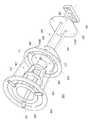
Translated fromKorean도 1은 본 발명에 따른 저추력엔진의 추력측정을 위한 정밀추력측정장치의 구성을 나타낸 사시도,1 is a perspective view showing the configuration of a precision thrust measuring device for the thrust measurement of a low thrust engine according to the present invention,
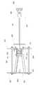
도 2는 본 발명에 따른 저추력엔진의 추력측정을 위한 정밀추력측정장치의 구성을 나타낸 부분 측단면도,Figure 2 is a partial side cross-sectional view showing the configuration of a precision thrust measuring device for the thrust measurement of the low thrust engine according to the present invention,
도 3은 본 발명에 따른 저추력엔진의 추력측정을 위한 정밀추력측정장치가 테스트 스탠드에 설치된 모습을 나타낸 측단면도.Figure 3 is a side cross-sectional view showing a state in which a precision thrust measuring device for measuring the thrust of the low thrust engine according to the present invention is installed on the test stand.
<도면의 주요 부분에 관한 부호의 설명><Explanation of symbols on main parts of the drawings>
10 : 엔진101 : 테스트 스탠드10: engine 101: test stand
110 : 공압 부재120, 130 : 제 1, 2고정 플레이트110:
140 : 고정 빔150, 160 : 제 1, 2유동 플레이트140:
170 : 프레임171 : 공압 부재 수납 프레임170: frame 171: pneumatic member storage frame
180 : 추력 전달용 빔 부재181, 183 : 제 1, 2추력 전달 빔180 thrust
185 : 로드190 : 압축형 로드셀185: Load 190: Compression Load Cell
200 : 압력 센서210 : 변위 센서200: pressure sensor 210: displacement sensor
본 발명은 정밀추력측정장치에 관한 것으로서, 상세하게는 공압장치를 이용하여 로드셀에 일정한 힘을 가하여 초기 상태에서 연소 시험동안 일정하게 힘을 유지하도록 한 상태에서 실제 연소시 발생하는 추력을 측정할 수 있도록 하는 저추력엔진의 추력측정을 위한 정밀추력측정장치에 관한 것이다.The present invention relates to a precision thrust measurement device, and in particular, by applying a constant force to the load cell using a pneumatic device can measure the thrust generated during actual combustion in a state to maintain a constant force during the combustion test in the initial state. The present invention relates to a precision thrust measurement device for thrust measurement of a low thrust engine.
일반적으로 로켓은 연료를 태워서 만드는 고압가스를 내뿜어 추진력을 얻는 장치이며, 이와 같은 방식의 엔진을 로켓엔진이라 한다. 로켓엔진은 크기에 비해 가장 큰 힘을 내는 엔진으로서, 같은 크기의 자동차 엔진보다 3,000배 이상의 힘을 낸다. 로켓은 매우 큰 힘을 내는 만큼 연료를 빨리 태우므로 짧은 시간 동안에 많은 연료를 소모하고, 높은 온도를 발생시킨다. 따라서 로켓기관은 높은 온도와 높은 압력, 그리고 강한 힘에 견디면서도 가벼워야 하기 때문에 매우 복잡하고 어려운 기술이 필요하다.In general, a rocket is a device that obtains propulsion by exhaling high-pressure gas produced by burning fuel, and such an engine is called a rocket engine. Rocket engines are the most powerful engines of their size, producing 3,000 times more power than engines of the same size. Rockets burn fuel as quickly as they can, consuming a lot of fuel in a short time and generating high temperatures. Therefore, rocket engines need to be very complex and difficult because they have to withstand high temperatures, high pressures and strong forces.
로켓의 작동 원리는 작용-반작용의 법칙으로, 물체에 어떤 힘이 가해져서 작용이 생기면 크기는 같지만 방향이 반대인 반작용이 생기는 것을 이용하여 강력한 로켓이 앞으로 나아갈 수 있도록 하는 것이다. 로켓의 연소실에서 특수 연료가 연소되면 매우 빠르게 팽창하는 가스가 만들어지며, 이 팽창가스의 압력은 로켓 안의 모든 방향으로 똑같이 작용하고, 어떤 한 방향으로 가해지는 압력은 그 반대 방향으로 가해지는 압력과 균형을 이룬다. 하지만 로켓 뒤쪽으로 흐르는 가스는 노즐을 통해 내뿜어져 로켓 앞쪽의 압력과 균형을 이루지 못하게 되어, 이 때 생기는 압력 차로 로켓이 앞으로 나아간다. 노즐을 통해 내뿜어지는 가스가 뉴턴의 운동 법칙에서 말하는 '작용'이고, 내뿜어지는 가스의 반대쪽인 앞쪽으로 로켓을 미는 추진력이 '반작용'이다.The working principle of a rocket is the law of action-reaction, which allows a powerful rocket to move forward by using reactions of the same magnitude but opposite direction when a force is applied to an object. The combustion of special fuel in the rocket's combustion chamber produces a gas that expands very quickly, the pressure of which is equally effective in all directions within the rocket, and the pressure in one direction is balanced against the pressure in the opposite direction. To achieve. However, the gas flowing behind the rocket is blown out through the nozzle and out of balance with the pressure in front of the rocket, which causes the rocket to move forward. The gas exhaled through the nozzle is the 'action' in Newton's law of motion, and the propulsion to push the rocket forward is the opposite.
로켓은 의한 추진 방식에 따라 액체 연료에 의한 방법과 고체 연료에 의한 방법 크게 두 가지로 나뉜다. 액체 연료에 의한 추진방법은, 기체 내에 채워져 있는 연료와 산화제의 연소에 의해서 생기는 가스를 기체 후방으로 고속 분출시켜 그 반동력으로 전진을 하며, 고체 연료에 의한 추진방법은, 기체 내에 채워져 있는 연료의 연소에 의해서 그 추진력을 이용하여 전진하게 된다. 상기 두 가지 추진방법중 비추력(단위 질량 추진제로 낼 수 있는 비거리)이 고체 로켓은 240㎞/㎏ 가량이지만 액체 로켓의 경우 이보다 훨씬 큰 450㎞/㎏ 가량까지 낼 수 있어 우주산업에서는 대부분 액체 추진제를 사용한다.The rocket is divided into two methods, a liquid fuel method and a solid fuel method. The liquid fuel propulsion method forwards the gas generated by the combustion of the fuel and oxidant filled in the gas to the rear of the gas at high speed and advances it with the reaction force. The solid fuel propulsion method uses the combustion of the fuel filled in the gas. By using its propulsion to move forward. Of these two propulsion methods, the non-thrust (flying distance that can be used as a unit mass propellant) is about 240 km / kg for solid rockets, but can be up to 450 km / kg for liquid rockets. use.
모든 시스템이 로켓 내부에 장착되어 있는 고체 로켓과는 달리, 액체 로켓은 외부에서 추진제 공급배관 및 제어장치들이 부착되어 있기 때문에 로드셀에서 나타나는 추력과 실제 추력과는 상당한 차이가 있다. 더욱이 저추력의 로켓일 경우 외부요소들에 의한 영향은 더욱 크기 때문에 이러한 오차를 최소화할 수 있도록 하여야 한다.Unlike solid rockets in which all systems are mounted inside the rocket, liquid rockets are significantly different from the thrust seen in the load cell and the actual thrust due to the external attachment of propellant supply lines and controls. Moreover, in case of low thrust rocket, the influence by external factors is much greater, so this error should be minimized.
그러나, 국내에 기 발표된 시스템이 없는 현실에서 기본적인 개념은 고체 로켓의 것을 참고했으나, 필연적으로 시스템 구조적 차이로 액체 로켓은 고체 로켓과는 다른 관점에서 접근해야 할 필요가 있다. 액체 로켓은 추진제 공급장치, 기타 측정 및 제어장치들이 엔진 외부에 부착되어 있는 형태로, 이들의 영향을 무시하고 얻는 추력은 무의미하다고 할 수 있다. 미리 추력측정시스템에 일정한 힘을 가해 추력손실을 가져오는 요소들을 상쇄한 상태에서 연소시험을 실시하여야만 액체 로켓 엔진의 정확한 추력을 얻을 수 있다.However, in the reality that there is no system announced in Korea, the basic concept refers to the solid rocket, but inevitably, the liquid structure rocket needs to be approached from a different point of view than the solid rocket. Liquid rockets are propellant supplies and other measurement and control devices attached to the outside of the engine, and the thrust gains are negligible. Accurate thrust of a liquid rocket engine can be obtained only by performing a combustion test with a certain force applied to the thrust measurement system in advance to compensate for the thrust loss.
따라서, 본 발명은 상기와 같은 문제점을 해결하기 위한 것으로, 추력 측정시 공압을 이용하여 로드셀에 일정한 힘을 유지시켜 추력 손실의 요소를 상쇄시킴으로써 정확히 추력을 측정할 수 있고, 추력 측정시에도 공압을 제어하여 추력을 보정할 수 있도록 하는 저추력엔진의 추력측정을 위한 정밀추력측정장치를 제공하는데 그 목적이 있다.Accordingly, the present invention is to solve the above problems, it is possible to accurately measure the thrust by maintaining a constant force in the load cell by using the pneumatic pressure during the thrust measurement to offset the element of the thrust loss, the pneumatic pressure in the thrust measurement It is an object of the present invention to provide a precision thrust measuring device for thrust measurement of a low thrust engine to control the thrust correction.
상기와 같은 목적을 달성하기 위한 본 발명의 특징은, 공압에 의해 피스톤이 돌출되는 공압 부재와; 판형태의 링형으로 형성된 한쌍의 제 1, 2고정 플레이트와; 상기 제 1, 2고정 플레이트에 각각 연결되어 이들을 수평하게 고정시키는 복수의 고정 빔과; 상기 제 1, 2고정 플레이트의 내주면에서 일정 간격 이격되어 플렉서블 플레이트에 의해 좌우로 유동 가능하게 고정되며, 판형태의 링형으로 형성된 한쌍의 제 1, 2유동 플레이트와; 상기 제 1, 2유동 플레이트에 각각 연결되어 이들이 연동되도록 연결시키는 프레임과; 상기 제 2유동 플레이트와 연결되어 이의 유동에 따라 좌우로 이동되는 추력 전달용 빔 부재; 및 상기 추력 전달용 빔 부재에 전달되는 추력을 측정하는 압축형 로드셀을 포함하는 것을 특징으로 한다.Features of the present invention for achieving the above object, the pneumatic member for projecting the piston by pneumatic; A pair of first and second fixing plates formed in a ring shape in a plate shape; A plurality of fixed beams connected to the first and second fixing plates, respectively for horizontally fixing them; A pair of first and second flow plates which are spaced apart from each other on the inner circumferential surfaces of the first and second fixing plates so as to be movable from side to side by the flexible plate and are formed in a plate-like ring shape; A frame connected to each of the first and second flow plates so as to be linked to each other; A thrust transmission beam member connected to the second flow plate and moved left and right according to the flow thereof; And it characterized in that it comprises a compression type load cell for measuring the thrust transmitted to the thrust transmission beam member.
여기에서, 상기 제 1유동 플레이트는 엔진이 결합되고, 상기 제 2유동 플레 이트는 공압 부재가 결합되되 피스톤이 돌출되도록 형성된다.Here, the first flow plate is coupled to the engine, the second flow plate is formed so that the piston is coupled to the pneumatic member is coupled.
여기에서 또한, 상기 프레임은 상기 공압 부재를 내부에 수납이 가능하도록 일단이 개구된 원통형으로 형성되며, 상기 제 2유동 플레이트와 결합되는 공압 부재 수납 프레임과; 상기 공압 부재 수납 프레임과 결합되고, 상기 제 1유동 프레임에 연결되는 연결 프레임으로 구성된다.The frame may further include a pneumatic member accommodating frame having a cylindrical shape, one end of which may be opened to accommodate the pneumatic member therein, and coupled to the second flow plate; It is coupled to the pneumatic member receiving frame, it is composed of a connecting frame connected to the first flow frame.
여기에서 또, 상기 추력 전달 빔 부재는 테스트 스탠드를 관통하여 상기 제 2유동 플레이트에서 서로 대칭되도록 각각 고정되는 한쌍의 제 1, 2추력 전달 빔과; 상기 제 1, 2추력 전달 빔의 이동에 따라 상기 압축형 로드셀에 추력을 전달하도록 상기 제 1, 2추력 전달 빔의 끝단에 결합되는 로드와; 상기 제 1, 2추력 전달 빔이 관통되는 관통홀이 형성되고, 상기 로드와 대응되는 위치인 상기 테스트 스탠드의 일면에 고정되며, 상기 압축형 로드셀이 장착 고정되는 제 1지지 플레이트; 및 상기 제 1, 2추력 전달 빔이 관통되는 관통홀이 형성되고, 상기 제 2유동 플레이트와 대응되는 위치인 상기 테스트 스탠드의 타면에 고정되어 상기 공압 부재의 피스톤을 지지하는 제 2지지 플레이트를 포함한다.Here, the thrust transmission beam member includes a pair of first and second thrust transmission beams respectively penetrated through the test stand to be symmetrical with each other in the second flow plate; A rod coupled to the ends of the first and second thrust transmission beams so as to transmit thrust to the compressed load cell in accordance with the movement of the first and second thrust transmission beams; A first support plate having a through hole through which the first and second thrust transmission beams penetrate, and fixed to one surface of the test stand at a position corresponding to the rod, and to which the compressed load cell is mounted and fixed; And a second support plate having a through hole through which the first and second thrust transmission beams pass, and fixed to the other surface of the test stand at a position corresponding to the second flow plate to support the piston of the pneumatic member. do.
여기에서 또, 상기 저추력엔진의 추력측정을 위한 정밀추력측정장치는 상기 공압 부재에 가해지는 압력을 측정하는 압력 센서와; 상기 제 1, 2유동 플레이트의 변위를 측정하는 변위 센서를 더 포함하며, 상기 압축형 로드셀과, 압력 센서 및 변위 센서로부터 측정되는 신호를 이용하여 추력을 측정하고, 추력의 크기에 따라 단계적으로 상기 공압 부재에 공압을 가하면서 추력을 보정한다.Here, the precision thrust measuring device for the thrust measurement of the low thrust engine and a pressure sensor for measuring the pressure applied to the pneumatic member; Further comprising a displacement sensor for measuring the displacement of the first flow plate, the second flow plate, and measuring the thrust by using the signals measured from the compression type load cell, the pressure sensor and the displacement sensor, step by step according to the magnitude of the thrust The thrust is corrected while applying air pressure to the pneumatic member.
여기에서 또, 상기 압축형 로드셀은 상기 공압 부재에 공압이 가해져 일정 크기 이상의 추력이 가해진 상태에서 상기 엔진에 의해 발생되는 추력에 의해 떨어지는 추력을 측정한다.Here, the compression type load cell measures the thrust dropped by the thrust generated by the engine in a state in which pneumatic pressure is applied to the pneumatic member and a thrust of a predetermined magnitude or more is applied thereto.
이하, 본 발명에 따른 저추력엔진의 추력측정을 위한 정밀추력측정장치의 구성을 첨부된 도면을 참조하여 상세하게 설명하면 다음과 같다.Hereinafter, with reference to the accompanying drawings the configuration of a precision thrust measuring device for the thrust measurement of the low thrust engine according to the present invention will be described in detail.
도 1은 본 발명에 따른 저추력엔진의 추력측정을 위한 정밀추력측정장치의 구성을 나타낸 사시도이고, 도 2는 본 발명에 따른 저추력엔진의 추력측정을 위한 정밀추력측정장치의 구성을 나타낸 부분 측단면도이며, 도 3은 본 발명에 따른 저추력엔진의 추력측정을 위한 정밀추력측정장치가 테스트 스탠드에 설치된 모습을 나타낸 측단면도이다.1 is a perspective view showing the configuration of a precision thrust measuring device for the thrust measurement of a low thrust engine according to the present invention, Figure 2 is a part showing the configuration of a precision thrust measuring device for the thrust measurement of a low thrust engine according to the present invention 3 is a side cross-sectional view showing a state in which a precision thrust measuring device for thrust measurement of a low thrust engine according to the present invention is installed in a test stand.
도 1 내지 도 3을 참조하면, 본 발명에 따른 저추력엔진의 추력측정을 위한 정밀추력측정장치(100)는, 공압 부재(110)와, 제 1고정 플레이트(120)와, 제 2고정 플레이트(130)와, 고정 빔(140)과, 제 1유동 플레이트(150)와, 제 2유동 플레이트(160)와, 프레임(170)과, 추력 전달용 빔 부재(180)와, 압축형 로드셀(190)과, 압력 센서(200) 및 변위 센서(210)로 구성된다.1 to 3, the precision
먼저, 공압 부재(110)는 외부로부터 공급되는 질소 가스에 의해 피스톤(111)이 돌출되고, 공압이 가해지면 스프링(113)에 의해 피스톤(111)이 복원되도록 구성된다.First, the
그리고, 제 1고정 플레이트(120)는 판형태의 링형으로 형성된다.In addition, the
또한, 제 2고정 플레이트(130)는 제 1고정 플레이트(120)와 동일한 형태인 판형태의 링형으로 형성된다.In addition, the
또, 고정 빔(140)은 제 1고정 플레이트(120) 및 제 2고정 플레이트(130)에서 각각 연결되되, 3개가 서로 대칭되도록 고정되어 제 1고정 플레이트(120)와, 제 2고정 플레이트(130)를 수평하게 고정시킨다.In addition, the
한편, 제 1유동 플레이트(150)는 제 1고정 플레이트(120)의 내주면에서 일정 간격 이격되어 서로 대칭되는 3개의 플렉서블 플레이트(151)에 의해 좌우로 유동 가능하게 고정되며, 판형태의 링형으로 형성되고, 엔진(10)이 결합된다.Meanwhile, the
그리고, 제 2유동 플레이트(160)는 제 2고정 플레이트(130)의 내주면에서 일정 간격 이격되어 서로 대칭되는 3개의 플렉서블 플레이트(151)에 의해 좌우로 유동 가능하게 고정되며, 판형태의 링형으로 형성되고, 공압 부재(110)가 결합되되, 피스톤(111)이 돌출되도록 형성된다.In addition, the
또한, 프레임(170)은 공압 부재 수납 프레임(171)과, 연결 프레임(173)으로 구성된다.The
공압 부재 수납 프레임(171)은 제 1유동 플레이트(150)와, 제 2유동 플레이트(160)를 연동시키도록 공압 부재(110)를 내부에 수납이 가능하도록 일단이 개구된 원통형으로 형성되며, 제 2유동 플레이트(160)와 용접에 의해 결합된다. 여기에서, 공압 부재 수납 프레임(171)은 공압 부재(110)의 피스톤(111)으로 질소 가스를 배관을 통해 공급할 수 있도록 가스 공급홀(도시 생략)이 측면에 형성된다.The pneumatic
연결 프레임(173)은 공압 부재 수납 프레임(171)과 결합되고, 제 1유동 플레이트(150)에 용접에 의해 결합된다.The connecting
또, 추력 전달용 빔 부재(180)는 제 1추력 전달 빔(181)과, 제 2추력 전달 빔(183)과, 로드(185)와, 제 1지지 플레이트(187) 및 제 2지지 플레이트(189)로 구성된다.The thrust
제 1추력 전달 빔(181) 및 제 2추력 전달 빔(183)은 테스트 스탠드(101)를 관통하여 제 2유동 플레이트(160)에서 서로 대칭되도록 각각 고정된다.The first
로드(185)는 제 1추력 전달 빔(181)과 제 2추력 전달 빔(183)의 좌, 우이동에 따라 압축형 로드셀(190)에 추력을 전달하도록 제 1추력 전달 빔(181)과 제 2추력 전달 빔(183)의 끝단에 결합된다.The
제 1지지 플레이트(187)는 제 1추력 전달 빔(181)과 제 2추력 전달 빔(183)이 관통되는 관통홀(187-1)이 형성되고, 로드(185)와 대응되는 위치인 테스트 스탠드(101)의 일면에 고정되며, 압축형 로드셀(190)이 장착 고정된다.The
제 2지지 플레이트(189)는 제 1추력 전달 빔(181)과 제 2추력 전달 빔(183)이 관통되는 관통홀(189-1)이 형성되고, 제 2유동 플레이트(160)와 대응되는 위치인 테스트 스탠드(101)의 타면에 고정되어 공압 부재(110)의 피스톤(111)을 지지한다.The second supporting
그리고, 압축형 로드셀(190)은 로드(185)에서 가해지는 추력을 측정하도록 제 1지지 플레이트(187)에 고정되어 로드(185)에 대응된다.In addition, the
압력 센서(200)는 질소를 공급하는 배관에 설치되어 공압 부재(110)에 가해지는 압력을 측정한다.The
변위 센서(210)는 제 1유동 플레이트(150)와 제 2유동 플레이트(160)의 일측에 설치되어 이들의 변위를 측정한다.The
이하, 본 발명에 따른 저추력엔진의 추력측정을 위한 정밀추력측정장치의 동작 및 작용을 첨부된 도면을 참조하여 상세하게 설명하면 다음과 같다.Hereinafter, with reference to the accompanying drawings the operation and action of the precision thrust measuring device for the thrust measurement of the low thrust engine according to the present invention will be described.
먼저, 니은자 형태의 콘크리트를 이용하여 테스트 스탠드(101)를 형성하는 데, 측벽에 제 1추력 전달 빔(181)과 제 2추력 전달 빔(183)이 관통될 수 있는 홀(101-1)을 형성한다.First, the
그런 다음, 테스트 스탠드(101) 측벽의 외벽에 제 1지지 플레이트(187)를 고정시키고, 내벽에 제 2지지 플레이트(189)를 고정 설치하는 데, 이때 제 1지지 플레이트(187)의 관통홀(187-1)과, 제 2지지 플레이트(189)의 관통홀(189-1) 및 측벽에 형성된 홀(101-1)을 일치시켜 고정시킨다.Then, the
그리고, 테스트 스탠드(101)의 외벽에 형성된 제 1지지 플레이트(187)에 압축형 로드셀(190)을 고정시킨다.Then, the compression
한편, 제 1유동 플레이트(150)와 제 2유동 플레이트(160)에 프레임(170)을 고정시킨 상태에서 제 1고정 플레이트(120)와 제 2고정 플레이트(130)를 고정 빔(140)으로 서로 고정한 후, 제 1유동 플레이트(150)와 제 2유동 플레이트(160)를 플렉서블 플레이트(151)를 이용하여 제 1고정 플레이트(120)와 제 2고정 플레이트(130)에 결합시킨다.Meanwhile, the
그런 다음, 프레임(170)의 공압 부재 수납 프레임(171)에 공압 부재(110)를 수납하여 고정시키고, 공압 부재(110)의 피스톤(111)이 제 2지지 플레이트(189)와 접촉되도록 한 상태가 되도록 테스트 스탠드(101)의 수평면에 제 1고정 플레이트(120)와 제 2고정 플레이트(130)를 안착시킨다. 이때, 제 1고정 플레이트(120)와 제 2고정 플레이트(130)는 유동이 방지되도록 지지판 및 볼트에 의해 테스트 스탠드(101)에 고정 설치되는 것이 바람직하다.Then, the
이러한 상태에서 로드(185)가 끝단에 결합된 제 1추력 전달 빔(181)과 제 2추력 전달 빔(183)을 테스트 스탠드(101)의 외벽에서 내벽으로 삽입한 후 제 2유동 플레이트(160)에 결합 고정시킨다. 이때, 로드(185)는 압축형 로드셀(190)과 대응되도록 한다.In this state, the
그런 다음, 제 1유동 플레이트(150)에 엔진(10)을 장착하고, 엔진(10)과 관련된 모든 배관 등의 장치를 모두 설치한 다음, 압력 센서(200)와 변위 센서(210)를 해당 위치에 각각 설치하여 측정 준비를 완료한다.Then, the
이하, 추력 측정 과정을 설명하면, 추력 측정을 위해서는 다음과 같은 요소의 측정이 선행되어야한다.In the following, the thrust measurement process will be described. In order to measure the thrust, the following elements should be measured.
먼저, 공압 부재(110)에 질소 가스를 이용하여 압력(Pa,i)을 단계적으로 가하면 외부에 힘(Fa,i)으로 작용하여 아래의 수학식 1과 같은 힘 평형을 이룬다.First, when pressure Pa, i is gradually applied to the

그리고, 로드(185)의 힘 T1, T2(반력)는 아래의 수학식 2와 같은 조건을 만족한다.In addition, the forces T1 and T 2 (reaction force) of the

한편, 구조적 연결에 의한 반작용은 아래의 수학식 3과 같다.On the other hand, the reaction by the structural connection is shown in Equation 3 below.

또한, 지지에 의한 반작용은 아래의 수학식 4와 같다.In addition, the reaction by the support is shown in Equation 4 below.

따라서, 힘(Fa,i)은 아래의 수학식 5와 같이 구해진다.Therefore, the forcesFa and i are obtained as shown in Equation 5 below.

그리고, 상기의 수학식으로부터 아래의 수학식 6을 얻을 수 있다.The following equation (6) can be obtained from the above equation.


한편, 실험 시작전에 위의 표 1에 나타난 바와 같이 제 1유동 플레이트(150)와, 제 2유동 플레이트(160)가 평행한 상태인 초기상태(a)에서 공압 부재(110)에 일정한 압력(Pa,max)을 공급하여 가압 상태(b)로 변경한다.On the other hand, as shown in Table 1 above before the experiment, the
이러한 상태에서 엔진(10)의 연소가 시작되면 추가적인 힘(Freal(t))이 제 1유동 플레이트(150)와, 제 2유동 플레이트(160)에 작용하기 시작한다.In this state, when the combustion of the
이 힘(Freal(t))은 대략 x축선 상의 추력과 같다. 제 1유동 플레이트(150)와, 제 2유동 플레이트(160)는 ΔX(t)만큼 이동하고, 로드(185)와 로드셀(190)의 반력은 줄어들게 된다.This force Freal (t) is approximately equal to the thrust on the x-axis. The
이 상태에서 표 1에 나타난 바와 같이 연소 시험(c)이 진행되면, 아래의 수학식 7과 같은 관계식이 세워진다.In this state, when the combustion test (c) proceeds as shown in Table 1, a relational expression as shown in Equation 7 below is established.

따라서, 압력 센서(200)와, 로드셀(190)과, 변위 센서(210)를 이용하여 Pa(t), Froadsell(t), ΔX(t)를 동시에 측정하면, 수학식 7을 이용하여 실제 추력(Freal(t))을 계산할 수가 있게 된다.Therefore, when Pa (t), Froadsell (t), and ΔX (t) are simultaneously measured using the
또한, 측정시에도 공압 부재(110)에 가해지는 질소 가스의 압력을 조절하여 저추력엔진의 지상 연소시 추력에 영향을 미칠 수 있는 요소들을 보정할 수 있다.In addition, during the measurement, the pressure of the nitrogen gas applied to the
상기와 같이 구성되는 본 발명인 저추력엔진의 추력측정을 위한 정밀추력측정장치에 따르면, 추력 측정시 공압을 이용하여 로드셀에 일정한 힘을 유지시켜 추력 손실의 요소를 상쇄시킴으로써 정확히 추력을 측정할 수 있고, 추력 측정시에도 공압을 제어하여 추력을 보정할 수 있다.According to the precise thrust measuring device for the thrust measurement of the low thrust engine of the present invention configured as described above, it is possible to accurately measure the thrust by offsetting the elements of the thrust loss by maintaining a constant force in the load cell using pneumatic pressure during thrust measurement In thrust measurement, thrust can be compensated by controlling the pneumatic pressure.
Claims (6)
Translated fromKoreanPriority Applications (1)
| Application Number | Priority Date | Filing Date | Title |
|---|---|---|---|
| KR1020040100926AKR100758703B1 (en) | 2004-12-03 | 2004-12-03 | Precision thrust measurement device for thrust measurement of low thrust engine |
Applications Claiming Priority (1)
| Application Number | Priority Date | Filing Date | Title |
|---|---|---|---|
| KR1020040100926AKR100758703B1 (en) | 2004-12-03 | 2004-12-03 | Precision thrust measurement device for thrust measurement of low thrust engine |
Publications (2)
| Publication Number | Publication Date |
|---|---|
| KR20060062171Atrue KR20060062171A (en) | 2006-06-12 |
| KR100758703B1 KR100758703B1 (en) | 2007-09-14 |
Family
ID=37158370
Family Applications (1)
| Application Number | Title | Priority Date | Filing Date |
|---|---|---|---|
| KR1020040100926AExpired - Fee RelatedKR100758703B1 (en) | 2004-12-03 | 2004-12-03 | Precision thrust measurement device for thrust measurement of low thrust engine |
Country Status (1)
| Country | Link |
|---|---|
| KR (1) | KR100758703B1 (en) |
Cited By (7)
| Publication number | Priority date | Publication date | Assignee | Title |
|---|---|---|---|---|
| KR100830055B1 (en)* | 2007-04-24 | 2008-05-19 | 국방과학연구소 | Thrust Test Bench |
| KR101297583B1 (en)* | 2011-12-23 | 2013-08-19 | 한국항공우주연구원 | Micro thrust measurement equipment for satellite thruster |
| CN106595935A (en)* | 2016-12-14 | 2017-04-26 | 中国燃气涡轮研究院 | Aero-engine vector force test stand capable of realizing self-decoupling |
| KR101965579B1 (en)* | 2017-10-31 | 2019-04-04 | 주식회사 한화 | Conbustion test apparatus of rocket engine and thrust measurement method of rocket engine using the same |
| CN110259607A (en)* | 2019-07-31 | 2019-09-20 | 西安航天动力研究所 | A kind of variable thrust rocket engine or motor power room performance testing device |
| CN111559517A (en)* | 2020-06-17 | 2020-08-21 | 安徽九州云箭航天技术有限公司 | A cold air engine thrust measurement device |
| PL442440A1 (en)* | 2022-10-04 | 2024-04-08 | Politechnika Warszawska | Measuring station for measuring engine thrust |
Families Citing this family (3)
| Publication number | Priority date | Publication date | Assignee | Title |
|---|---|---|---|---|
| KR101054734B1 (en) | 2008-12-31 | 2011-08-08 | 한국항공우주연구원 | Thrust measuring device and method |
| KR101851074B1 (en)* | 2016-10-17 | 2018-04-20 | 주식회사 한화 | Ground fire testing device and method for thrust measurement of solid rocket motor using canted nozzle |
| KR102862825B1 (en) | 2023-05-17 | 2025-09-22 | 충남대학교산학협력단 | Vertical thrust measurement devices |
Family Cites Families (7)
| Publication number | Priority date | Publication date | Assignee | Title |
|---|---|---|---|---|
| JPS61195325A (en)* | 1985-02-26 | 1986-08-29 | Mitsubishi Heavy Ind Ltd | Thrust loading device for rotary shaft |
| US4788855A (en)* | 1987-03-03 | 1988-12-06 | The Boeing Company | Test apparatus for measuring jet engine thrust |
| JP2856277B2 (en)* | 1996-07-04 | 1999-02-10 | 防衛庁技術研究本部長 | Jet engine thrust measurement device |
| US6032545A (en)* | 1998-04-17 | 2000-03-07 | California Polytechnic State University Foundation | Nozzle flow thrust vector measurement |
| KR100408093B1 (en)* | 2000-07-14 | 2003-12-01 | 한국항공우주연구원 | Measurement Method of Horizontal Six-Component Thrust |
| KR20020028065A (en)* | 2000-10-05 | 2002-04-16 | 김지석 | Apparatus for measuring thrust force of linear pulse motor |
| US6895756B2 (en)* | 2002-09-13 | 2005-05-24 | The Boeing Company | Compact swirl augmented afterburners for gas turbine engines |
- 2004
- 2004-12-03KRKR1020040100926Apatent/KR100758703B1/ennot_activeExpired - Fee Related
Cited By (9)
| Publication number | Priority date | Publication date | Assignee | Title |
|---|---|---|---|---|
| KR100830055B1 (en)* | 2007-04-24 | 2008-05-19 | 국방과학연구소 | Thrust Test Bench |
| KR101297583B1 (en)* | 2011-12-23 | 2013-08-19 | 한국항공우주연구원 | Micro thrust measurement equipment for satellite thruster |
| CN106595935A (en)* | 2016-12-14 | 2017-04-26 | 中国燃气涡轮研究院 | Aero-engine vector force test stand capable of realizing self-decoupling |
| CN106595935B (en)* | 2016-12-14 | 2019-10-18 | 中国燃气涡轮研究院 | Rack can be measured from uncoupled aero-engine vectorial force |
| KR101965579B1 (en)* | 2017-10-31 | 2019-04-04 | 주식회사 한화 | Conbustion test apparatus of rocket engine and thrust measurement method of rocket engine using the same |
| CN110259607A (en)* | 2019-07-31 | 2019-09-20 | 西安航天动力研究所 | A kind of variable thrust rocket engine or motor power room performance testing device |
| CN110259607B (en)* | 2019-07-31 | 2021-11-16 | 西安航天动力研究所 | Engine thrust chamber performance testing device for variable thrust rocket engine |
| CN111559517A (en)* | 2020-06-17 | 2020-08-21 | 安徽九州云箭航天技术有限公司 | A cold air engine thrust measurement device |
| PL442440A1 (en)* | 2022-10-04 | 2024-04-08 | Politechnika Warszawska | Measuring station for measuring engine thrust |
Also Published As
| Publication number | Publication date |
|---|---|
| KR100758703B1 (en) | 2007-09-14 |
Similar Documents
| Publication | Publication Date | Title |
|---|---|---|
| KR100758703B1 (en) | Precision thrust measurement device for thrust measurement of low thrust engine | |
| KR101059777B1 (en) | Thrust measurement and correction device of rocket engine and its method | |
| US5431010A (en) | High speed, amplitude variable thrust control method | |
| RU2554668C1 (en) | Rack for measurement of axial force of rocket engine traction | |
| CN105486441A (en) | Attitude-control engine vector thrust measurement and calibration integrated device and measurement method | |
| CN113928605B (en) | Micro-low gravity environment simulation device and method for variable mass load | |
| CN110702293B (en) | Air inlet thrust measuring device of supersonic engine test bed and using method | |
| CN109374166B (en) | Distributed measuring device and method | |
| Jain et al. | Design and analysis of 2-axis rocket motor stand for thrust vectoring | |
| KR101533963B1 (en) | Thrust measuring device for measuring roll moment of side jet thruster for guided missile | |
| Gram et al. | Laboratory simulation of blast loading on building and bridge structures | |
| Kobald et al. | The HyEnD stern hybrid sounding rocket project | |
| US11802803B2 (en) | Internal force transducer balance system for measuring aerodynamic interference forces | |
| KR20060011054A (en) | Abrasion property tester of material | |
| RU2667687C1 (en) | Gas dynamic aerospace chamber | |
| KR102862825B1 (en) | Vertical thrust measurement devices | |
| KR20200057471A (en) | Rocket thrust measuring device | |
| Groenig et al. | Experimental Hypersonic Flow Researc in Europe | |
| RU2770320C1 (en) | Gas-dynamic pressure chamber | |
| Vemula | Thrust Measurements on a Rocket Nozzle Using Flow-Field Diagnostics | |
| Brophy et al. | Effects of non-uniform mixture distributions on pulse detonation engine performance | |
| KR101441414B1 (en) | A ground test apparatus for variable nozzles in jet engine | |
| WHITEHEAD et al. | Pumped hydrazine miniaturized propulsion system | |
| LENG et al. | A detonation tube technique for simulating rocket plumes in a space environment. | |
| KR102336543B1 (en) | Apparatus for measuring thrust |
Legal Events
| Date | Code | Title | Description |
|---|---|---|---|
| A201 | Request for examination | ||
| PA0109 | Patent application | St.27 status event code:A-0-1-A10-A12-nap-PA0109 | |
| PA0201 | Request for examination | St.27 status event code:A-1-2-D10-D11-exm-PA0201 | |
| R17-X000 | Change to representative recorded | St.27 status event code:A-3-3-R10-R17-oth-X000 | |
| R17-X000 | Change to representative recorded | St.27 status event code:A-3-3-R10-R17-oth-X000 | |
| R17-X000 | Change to representative recorded | St.27 status event code:A-3-3-R10-R17-oth-X000 | |
| E902 | Notification of reason for refusal | ||
| PE0902 | Notice of grounds for rejection | St.27 status event code:A-1-2-D10-D21-exm-PE0902 | |
| P11-X000 | Amendment of application requested | St.27 status event code:A-2-2-P10-P11-nap-X000 | |
| P13-X000 | Application amended | St.27 status event code:A-2-2-P10-P13-nap-X000 | |
| R18-X000 | Changes to party contact information recorded | St.27 status event code:A-3-3-R10-R18-oth-X000 | |
| PG1501 | Laying open of application | St.27 status event code:A-1-1-Q10-Q12-nap-PG1501 | |
| E902 | Notification of reason for refusal | ||
| PE0902 | Notice of grounds for rejection | St.27 status event code:A-1-2-D10-D21-exm-PE0902 | |
| P11-X000 | Amendment of application requested | St.27 status event code:A-2-2-P10-P11-nap-X000 | |
| P13-X000 | Application amended | St.27 status event code:A-2-2-P10-P13-nap-X000 | |
| E701 | Decision to grant or registration of patent right | ||
| PE0701 | Decision of registration | St.27 status event code:A-1-2-D10-D22-exm-PE0701 | |
| GRNT | Written decision to grant | ||
| PR0701 | Registration of establishment | St.27 status event code:A-2-4-F10-F11-exm-PR0701 | |
| PR1002 | Payment of registration fee | Fee payment year number:1 St.27 status event code:A-2-2-U10-U11-oth-PR1002 | |
| PG1601 | Publication of registration | St.27 status event code:A-4-4-Q10-Q13-nap-PG1601 | |
| PN2301 | Change of applicant | St.27 status event code:A-5-5-R10-R11-asn-PN2301 St.27 status event code:A-5-5-R10-R13-asn-PN2301 | |
| FPAY | Annual fee payment | Payment date:20100903 Year of fee payment:4 | |
| PR1001 | Payment of annual fee | Fee payment year number:4 St.27 status event code:A-4-4-U10-U11-oth-PR1001 | |
| LAPS | Lapse due to unpaid annual fee | ||
| PC1903 | Unpaid annual fee | Not in force date:20110908 Payment event data comment text:Termination Category : DEFAULT_OF_REGISTRATION_FEE St.27 status event code:A-4-4-U10-U13-oth-PC1903 | |
| PC1903 | Unpaid annual fee | Ip right cessation event data comment text:Termination Category : DEFAULT_OF_REGISTRATION_FEE Not in force date:20110908 St.27 status event code:N-4-6-H10-H13-oth-PC1903 | |
| P22-X000 | Classification modified | St.27 status event code:A-4-4-P10-P22-nap-X000 | |
| PN2301 | Change of applicant | St.27 status event code:A-5-5-R10-R11-asn-PN2301 St.27 status event code:A-5-5-R10-R13-asn-PN2301 | |
| PN2301 | Change of applicant | St.27 status event code:A-5-5-R10-R11-asn-PN2301 St.27 status event code:A-5-5-R10-R13-asn-PN2301 |