KR20060058830A - Separation method by multichannel electrophoresis device without individual sample inlet - Google Patents
Separation method by multichannel electrophoresis device without individual sample inletDownload PDFInfo
- Publication number
- KR20060058830A KR20060058830AKR1020040097820AKR20040097820AKR20060058830AKR 20060058830 AKR20060058830 AKR 20060058830AKR 1020040097820 AKR1020040097820 AKR 1020040097820AKR 20040097820 AKR20040097820 AKR 20040097820AKR 20060058830 AKR20060058830 AKR 20060058830A
- Authority
- KR
- South Korea
- Prior art keywords
- sample
- channel
- electrophoretic
- separation
- chip
- Prior art date
- Legal status (The legal status is an assumption and is not a legal conclusion. Google has not performed a legal analysis and makes no representation as to the accuracy of the status listed.)
- Ceased
Links
- 238000000926separation methodMethods0.000titleclaimsabstractdescription51
- 238000001962electrophoresisMethods0.000titleclaimsabstractdescription39
- 239000012454non-polar solventSubstances0.000claimsabstractdescription20
- 238000003860storageMethods0.000claimsabstractdescription11
- 108090000623proteins and genesProteins0.000claimsabstractdescription10
- 102000004169proteins and genesHuman genes0.000claimsabstractdescription6
- 238000000034methodMethods0.000claimsdescription21
- 239000000126substanceSubstances0.000claimsdescription8
- XUIMIQQOPSSXEZ-UHFFFAOYSA-NSiliconChemical compound[Si]XUIMIQQOPSSXEZ-UHFFFAOYSA-N0.000claimsdescription6
- 239000003921oilSubstances0.000claimsdescription6
- 229910052710siliconInorganic materials0.000claimsdescription6
- 239000010703siliconSubstances0.000claimsdescription6
- 229920002545silicone oilPolymers0.000claimsdescription5
- VYPSYNLAJGMNEJ-UHFFFAOYSA-NSilicium dioxideChemical compoundO=[Si]=OVYPSYNLAJGMNEJ-UHFFFAOYSA-N0.000claimsdescription4
- 239000002184metalSubstances0.000claimsdescription4
- 239000002480mineral oilSubstances0.000claimsdescription4
- 235000010446mineral oilNutrition0.000claimsdescription4
- 229920000098polyolefinPolymers0.000claimsdescription3
- 239000011347resinSubstances0.000claimsdescription3
- 229920005989resinPolymers0.000claimsdescription3
- 239000000377silicon dioxideSubstances0.000claimsdescription2
- 208000036829Device dislocationDiseases0.000claims1
- 238000003825pressingMethods0.000claims1
- 238000009792diffusion processMethods0.000abstractdescription9
- 238000004519manufacturing processMethods0.000abstractdescription6
- 238000005070samplingMethods0.000abstractdescription2
- 239000002904solventSubstances0.000abstractdescription2
- 150000001875compoundsChemical class0.000abstract1
- 238000002347injectionMethods0.000description11
- 239000007924injectionSubstances0.000description11
- 230000005684electric fieldEffects0.000description7
- 238000004458analytical methodMethods0.000description6
- 239000000872bufferSubstances0.000description6
- 238000005516engineering processMethods0.000description4
- 239000000243solutionSubstances0.000description4
- 239000007853buffer solutionSubstances0.000description3
- 238000005520cutting processMethods0.000description2
- 230000000694effectsEffects0.000description2
- 238000012252genetic analysisMethods0.000description2
- 238000002360preparation methodMethods0.000description2
- OSBLTNPMIGYQGY-UHFFFAOYSA-N2-amino-2-(hydroxymethyl)propane-1,3-diol;2-[2-[bis(carboxymethyl)amino]ethyl-(carboxymethyl)amino]acetic acid;boric acidChemical compoundOB(O)O.OCC(N)(CO)CO.OC(=O)CN(CC(O)=O)CCN(CC(O)=O)CC(O)=OOSBLTNPMIGYQGY-UHFFFAOYSA-N0.000description1
- 229920000178Acrylic resinPolymers0.000description1
- 239000004925Acrylic resinSubstances0.000description1
- KCXVZYZYPLLWCC-UHFFFAOYSA-NEDTAChemical compoundOC(=O)CN(CC(O)=O)CCN(CC(O)=O)CC(O)=OKCXVZYZYPLLWCC-UHFFFAOYSA-N0.000description1
- 239000008051TBE bufferSubstances0.000description1
- 230000015572biosynthetic processEffects0.000description1
- 230000000903blocking effectEffects0.000description1
- 239000003795chemical substances by applicationSubstances0.000description1
- 238000009833condensationMethods0.000description1
- 230000005494condensationEffects0.000description1
- 230000008021depositionEffects0.000description1
- 238000013461designMethods0.000description1
- 238000001514detection methodMethods0.000description1
- 238000001035dryingMethods0.000description1
- 229920001971elastomerPolymers0.000description1
- 239000000806elastomerSubstances0.000description1
- 239000003822epoxy resinSubstances0.000description1
- 230000005284excitationEffects0.000description1
- 239000012530fluidSubstances0.000description1
- 238000009434installationMethods0.000description1
- 150000002500ionsChemical class0.000description1
- 239000000463materialSubstances0.000description1
- 239000000203mixtureSubstances0.000description1
- 239000000178monomerSubstances0.000description1
- 239000005011phenolic resinSubstances0.000description1
- 239000004033plasticSubstances0.000description1
- 229920003023plasticPolymers0.000description1
- 229920000647polyepoxidePolymers0.000description1
- 229920000642polymerPolymers0.000description1
- 229920001296polysiloxanePolymers0.000description1
- 238000012545processingMethods0.000description1
- 238000011160researchMethods0.000description1
- 229920002050silicone resinPolymers0.000description1
- 238000012360testing methodMethods0.000description1
- 229920002803thermoplastic polyurethanePolymers0.000description1
- 239000002699waste materialSubstances0.000description1
Images


Classifications
- G—PHYSICS
- G01—MEASURING; TESTING
- G01N—INVESTIGATING OR ANALYSING MATERIALS BY DETERMINING THEIR CHEMICAL OR PHYSICAL PROPERTIES
- G01N27/00—Investigating or analysing materials by the use of electric, electrochemical, or magnetic means
- G01N27/26—Investigating or analysing materials by the use of electric, electrochemical, or magnetic means by investigating electrochemical variables; by using electrolysis or electrophoresis
- G01N27/416—Systems
- G01N27/447—Systems using electrophoresis
- G01N27/44756—Apparatus specially adapted therefor
- G01N27/44782—Apparatus specially adapted therefor of a plurality of samples
- B—PERFORMING OPERATIONS; TRANSPORTING
- B01—PHYSICAL OR CHEMICAL PROCESSES OR APPARATUS IN GENERAL
- B01L—CHEMICAL OR PHYSICAL LABORATORY APPARATUS FOR GENERAL USE
- B01L9/00—Supporting devices; Holding devices
- B01L9/52—Supports specially adapted for flat sample carriers, e.g. for plates, slides, chips
- B01L9/527—Supports specially adapted for flat sample carriers, e.g. for plates, slides, chips for microfluidic devices, e.g. used for lab-on-a-chip
- G—PHYSICS
- G01—MEASURING; TESTING
- G01N—INVESTIGATING OR ANALYSING MATERIALS BY DETERMINING THEIR CHEMICAL OR PHYSICAL PROPERTIES
- G01N27/00—Investigating or analysing materials by the use of electric, electrochemical, or magnetic means
- G01N27/26—Investigating or analysing materials by the use of electric, electrochemical, or magnetic means by investigating electrochemical variables; by using electrolysis or electrophoresis
- G01N27/416—Systems
- G01N27/447—Systems using electrophoresis
- G01N27/44704—Details; Accessories
- G01N27/44717—Arrangements for investigating the separated zones, e.g. localising zones
- G01N27/4473—Arrangements for investigating the separated zones, e.g. localising zones by electric means
- G—PHYSICS
- G01—MEASURING; TESTING
- G01N—INVESTIGATING OR ANALYSING MATERIALS BY DETERMINING THEIR CHEMICAL OR PHYSICAL PROPERTIES
- G01N33/00—Investigating or analysing materials by specific methods not covered by groups G01N1/00 - G01N31/00
- G01N33/0004—Gaseous mixtures, e.g. polluted air
- G01N33/0009—General constructional details of gas analysers, e.g. portable test equipment
- G01N33/0022—General constructional details of gas analysers, e.g. portable test equipment using a number of analysing channels
- G—PHYSICS
- G01—MEASURING; TESTING
- G01N—INVESTIGATING OR ANALYSING MATERIALS BY DETERMINING THEIR CHEMICAL OR PHYSICAL PROPERTIES
- G01N27/00—Investigating or analysing materials by the use of electric, electrochemical, or magnetic means
- G01N27/26—Investigating or analysing materials by the use of electric, electrochemical, or magnetic means by investigating electrochemical variables; by using electrolysis or electrophoresis
- G01N27/416—Systems
- G01N27/447—Systems using electrophoresis
- G01N27/44756—Apparatus specially adapted therefor
- G01N27/44791—Microapparatus
Landscapes
- Health & Medical Sciences (AREA)
- Chemical & Material Sciences (AREA)
- Life Sciences & Earth Sciences (AREA)
- Molecular Biology (AREA)
- Analytical Chemistry (AREA)
- Chemical Kinetics & Catalysis (AREA)
- Physics & Mathematics (AREA)
- Biochemistry (AREA)
- General Health & Medical Sciences (AREA)
- General Physics & Mathematics (AREA)
- Immunology (AREA)
- Pathology (AREA)
- Electrochemistry (AREA)
- Dispersion Chemistry (AREA)
- Clinical Laboratory Science (AREA)
- Engineering & Computer Science (AREA)
- Medicinal Chemistry (AREA)
- Food Science & Technology (AREA)
- Combustion & Propulsion (AREA)
- Sampling And Sample Adjustment (AREA)
- Apparatus Associated With Microorganisms And Enzymes (AREA)
Abstract
Translated fromKoreanDescription
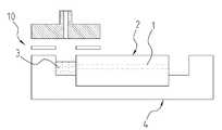
Translated fromKorean도 1은 본 발명이 적용하는 개별 시료 주입구가 생략된 다중채널 초소형 전기영동장치.1 is a multi-channel microelectrophoresis apparatus is omitted, the individual sample inlet is applied to the present invention.
도 2는 종래의 시료도입 기술에서 요구되는 개별 시료투입구 및 십자유로 형성용 가지관을 구비한 전기영동칩 상의 전형적인 시료주입용 십자유로.Figure 2 is a typical sample injection cross flow path on an electrophoretic chip having a separate sample inlet and branch pipe for forming a cross flow path required in the conventional sample introduction technology.
도3은 본 발명에 따른 전기영동칩을 고정하는 장치.Figure 3 is an apparatus for fixing an electrophoretic chip according to the present invention.
도4는 본 발명에 따른 자동간격 조정형 시료흡입 및 토출기구.Figure 4 is an automatic spacing adjustable sample suction and discharge mechanism according to the present invention.
도5는 본 발명의 비극성 용매 내에서 시료가 토출되는 동안 확산되거나 흩어지지 않음을 보이는 사진.5 is a photograph showing that the sample is not diffused or scattered while being discharged in the nonpolar solvent of the present invention.
도6은 본 발명의 전기장의 인가에 따라 시료가 분리관 안으로 도입되는 과정을 나타내는 사진.Figure 6 is a photograph showing a process in which the sample is introduced into the separation tube in accordance with the application of the electric field of the present invention.
도7은 본 발명에 따른 시료주입에서 먼저 도입된 DNA가 후속되는 이웃 분리관에 시료를 주입하는 것에 영향을 받지 않음을 나타내 보이는 사진.Figure 7 is a photograph showing that the DNA introduced in the sample injection according to the present invention is not affected by the injection of the sample into the subsequent neighboring separation tube.
도8은 본 발명의 전기장으로 주입된 시료가 계속되는 전기영동을 통해 성공 적으로 분리되는 과정을 나타내 보인 사진.Figure 8 is a photograph showing a process in which the sample injected into the electric field of the present invention is successfully separated through continuous electrophoresis.
- 도면의 부호설명 - -Explanation of Codes on Drawings-
1 : 모세분리관 2: 전기영동칩 3: 저장조1 capillary separation tube 2: electrophoretic chip 3: storage tank
4 : 고정판 5: 좌축고정장치 6: 우측고정장치4: fixing plate 5: left shaft fixing device 6: right fixing device
7: 탄성체판(실리콘판) 8: 전기영동채널 10: 전기영동장치7: Elastomer plate (silicon plate) 8: Electrophoresis channel 10: Electrophoresis device
본 발명은 초소화 다중채널 전기영동장치를 이용하여 전기영동 분석을 수행하는 기술에 관한 것이다.The present invention relates to a technique for performing electrophoretic analysis using a miniaturized multichannel electrophoretic apparatus.
초소화 다중채널 전기영동장치 기술은 화학물질, 유전자, 또는 단백질 등의 고속 전기영동분석을 빠르고 간편하게 수행할 수 있도록 하는 유용한 분석도구로 개발되고 있다.Miniaturized multichannel electrophoresis technology is being developed as a useful analytical tool that enables quick and easy high-speed electrophoresis analysis of chemicals, genes, or proteins.
종래의 전기영동칩은 도2와 같이 시료주입을 위한 별도의 시료투입구를 두고 이 시료투입구와 분리관 사이의 연결부의 십자로를 이용, 정교하게 시료를 분리관으로 주입하는 방식을 사용한다. [Seiler, K., etc., Anal. Chem. 1993, 65,1481-1488]. 시료도입용 십자유로를 사용한 종래의 시료주입 기술은 개별 시료주입구와 십자로의 형성을 요구하기 때문에 분리관의 배열이 복잡해지고 나아가 분리관의 배 열밀도를 높이는데 제약을 가한다. 이러한 이유로 현재 시판되고 있는 Agilent사의 DNA/RNA 전기영동칩의 경우, 칩 당 분리관은 하나 밖에 없으며, 시료도입구가 12개 설치되어 단일분리관을 사용해 12개의 시료가 차례로 분석된다. 최근 B. M. Paegel 등이 96채널 전기영동 칩을 발표한 바 있으나 [Paegel,P.M., etc., PNAS 2002, 99,574~579] 이 경우에도 각 채널에 요구되는 개별 시료투입구와 십자유로 때문에 칩의 구조가 방사형으로 설계되었다. 방사형 설계는 칩의 제조 및 절단에 기술적 어려움 또는 비경제성을 더할 뿐 아니라 회전하면서 동작하는 고도의 검출기술이 요구된다.The conventional electrophoretic chip uses a method of injecting a sample into the separation tube precisely by using a cross between the sample inlet and the separation tube having a separate sample inlet for sample injection as shown in FIG. Seiler, K., etc., Anal. Chem. 1993, 65,1481-1488. The conventional sample injection technique using the cross flow path for sample introduction requires the formation of individual sample inlets and crosses, which complicates the arrangement of the separation tube and further restricts the arrangement density of the separation tube. For this reason, Agilent's currently available DNA / RNA electrophoretic chip has only one separation tube per chip, and 12 sample inlets are installed to analyze 12 samples in sequence using a single separation tube. Recently, BM Paegel et al. Announced 96-channel electrophoresis chip [Paegel, PM, etc., PNAS 2002, 99,574 ~ 579]. In this case, the structure of the chip is radial due to the individual sample inlet and cross flow path required for each channel. Was designed as. Radial design not only adds technical difficulties or economics to the manufacture and cutting of chips, but also requires a high degree of detection technology that operates while rotating.
상기와 같은 문제점을 해결하고자, 이러한 시료도입용 십자유로를 제거하고 분리관 상에 시료저장조를 직접 설치하는 기존의 십자유로를 제거한 다중채널 칩들이 발표된 바 있으나 [Backhouse,J.W., etc., Electrophoresis 2000, 21, 150~156, Simpson,J.W., etc., Electrophoresis 2000, 21, 135~149], 이 경우에도 분리관 보다 상대적으로 매우 큰 개별 시료투입구가 분리관 상에 설치되기 때문에 분리관 간의 간격이 넓어지고, 또한 투입구의 가공이 비용이 많이 들고 기술적으로 쉽지 않은 문제점들이 지적될 수 있다.In order to solve the above problems, the multi-channel chips have been released to remove the cross-channel for the sample introduction and remove the existing cross-channel to install the sample reservoir directly on the separation pipe [Backhouse, JW, etc.,
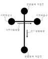
본 연구그룹에서는 선행연구에서 이러한 문제점을 극복하기 위해 도 1과 같이 개별 시료저장조가 제거된 하나의 시료저장조로만 된 단순구조의 전기영동장치가 제안되었는데 [한국특허출원번호 2004-40408], 이 경우 시료를 투입할 경우 하나의 시료저장조에서 시료를 투입할 때, 시료의 확산에 의해 다른 모세관으로 시료가 흘러들어가서 전기영동 되는 현상이 발생하여 분석의 정확도를 저해할 수 있는 문제점이 있었다.In order to overcome this problem in the previous research group, the electrophoretic device having a simple structure consisting of a single sample reservoir in which individual sample reservoirs are removed is proposed as shown in FIG. 1 [Korean Patent Application No. 2004-40408]. In this case, when the sample is added, when the sample is added from one sample reservoir, the sample flows into another capillary tube by electrophoresis and electrophoresis occurs, which may hamper the accuracy of the analysis.
본 발명은 상기한 바와 같은 문제점을 해결하고자 하는 것으로, 본 발명의 목적은 개별 시료주입구나 시료도입용 십자로가 원천적으로 제거된 단순한 구조의 초소화 다중채널 전기영동장치를 실용화하는데 필요한 독창적 시료도입기술을 구현하는 방법을 제공하는 것이다.The present invention is to solve the problems as described above, the object of the present invention is the original sample introduction technology required for the practical use of a miniaturized multi-channel electrophoresis apparatus of a simple structure in which the individual sample injection or the sample introduction cross is essentially removed. To provide a way to implement it.
또한, 본 발명은 본 발명자가 기 발명하여 출원한 선행발명[한국특허출원번호 2004-40408]에 따른 고밀도의 분리관을 설치가능하고, 저렴한 비용으로 장치를 제작될 수 있는 단순한 구조의 전기영동장치를 이용하여 시료를 더욱 효과적으로 주입할 수 있는 방법을 제공하는 것이다.In addition, the present invention can install a high-density separation tube according to the prior invention [Korea Patent Application No. 2004-40408] filed by the inventor of the present invention, an electrophoretic device of a simple structure that can be manufactured at low cost It is to provide a method that can be injected more effectively using the sample.
또한, 본 발명은 분리관이 평행직선형으로 배열되는 장점을 살려 칩의 길이를 필요에 따라 다양하게 변화시킬 수 있도록 하는 시료의 효과적 분리방법 및 그 장치를 제공하고자 한다.In addition, the present invention is to provide an effective separation method and apparatus for separating the sample to vary the length of the chip as needed by taking advantage of the parallel arrangement of the separation tube.
본 발명의 또 다른 목적은 상기와 같이 조절가능한 칩을 사용하고, 효과적 주입방법을 개발하는 것에 따라, 서로 다른 분리능을 요구하는 다양한 종류의 유전자분석에 모두 적용될 수 있는 전기영동장치를 제공하고자 한다.
Still another object of the present invention is to provide an electrophoretic apparatus that can be applied to all kinds of genetic analysis requiring different resolutions by using an adjustable chip as described above and developing an effective injection method.
본 발명은 상기와 같이 하나의 시료저장조로만 된 단순구조의 전기영동장치 에서 확산에 의해 야기되는 분리의 정확도를 저해하는 현상을 방지하기 위하여, 비극성 용매를 시료저장조에 저장하여 투입하고, 해당 시료토출관에 의해 시료를 비극성용매 중에 투입하고 해당 분리관 전면에 토출된 각 시료들은 각 토출관의 종단부 금속부에 걸리는 음의 전장 (또는 양의 전장)에 의해 해당분리관으로 도입하여 전기영동함으로써 본 발명을 완성하게 되었다.In the present invention, in order to prevent the phenomenon of impairing the accuracy of separation caused by diffusion in the electrophoretic apparatus having a simple structure consisting of only one sample storage tank, the non-polar solvent is stored in the sample storage tank and added to the sample. The sample is introduced into the non-polar solvent by the discharge tube, and each sample discharged to the front of the separator tube is introduced into the separator tube by a negative electric field (or positive electric field) applied to the metal part of the end of each discharge tube and subjected to electrophoresis. Thus, the present invention has been completed.
즉, 본 발명은 시료저장조에 비극성용매를 저장하고, 이 비극성 용매 저장조에 시료를 투입하여 확산을 방지하는 단계를 포함하는 것을 본 발명의 하나의 특징부로 한다. 본 발명에 사용한 비극성 용매는 점도를 가지는 실리콘오일, 광유 등의 비극성 오일을 사용하는 것이 바람직하며, 좋게는 실리콘오일을 사용하는 것이 가장 좋다. 사용하는 비극성 용매의 점도는 크게 제한을 받지 않으므로 적절히 선택하여 사용할 수 있다.That is, the present invention includes one step of storing a nonpolar solvent in a sample storage tank and adding a sample to the nonpolar solvent storage tank to prevent diffusion. As the nonpolar solvent used in the present invention, it is preferable to use nonpolar oils such as silicone oil and mineral oil having a viscosity, and preferably silicon oil. Since the viscosity of the nonpolar solvent to be used is not particularly limited, it can be appropriately selected and used.
이하는 본 발명에 따른 유전자 또는 단백질 등을 고속으로 분리가능한 다중채널 전기영동장치를 이용한 분리단계에 대하여 구체적으로 설명한다.Hereinafter will be described in detail for the separation step using a multi-channel electrophoresis apparatus capable of separating genes or proteins according to the present invention at high speed.
1) 다중채널 전기영동칩의 구조 및 설치1) Structure and installation of multichannel electrophoretic chip
다중채널 전기영동칩의 제작은 본 출원인이 출원한 한국특허출원번호 2004-40408호에 기재된 방식으로 제조할 수 있다. 이를 간략히 설명하면, 본 발명은 도 1에서 도식한 바와 같이, 내경 10 ~ 200㎛, 외경이 300 ~ 400㎛의 용융실리카 모세관이 상기 모세관을 배열할 수 있는 길이방향으로 적당한 폭과 깊이로 홈이 형성된 플라스틱기저판의 홈에 여러 줄의 모세관을 배열하고 에폭시수지, 우레탄수지, 페 놀수지, 실리콘수지 또는 아크릴수지와 같은 침적용 수지를 경화제에 의해 경화하여 생성할 수 있는 단량체 또는 올리고머를 충진하여 상기 수지가 형성되도록 경화하여 제조한 다중채널 전기영동칩(2)을 전기영동장치(10)의 저면에 삽입함으로써 비극성용매가 저장되는 저장조(3)를 형성하는 다중채널전기영동칩(2)을 설치한 전기영동장치(10)를 완성한다.The fabrication of the multichannel electrophoretic chip can be manufactured in the manner described in Korean Patent Application No. 2004-40408 filed by the present applicant. Briefly, the present invention, as shown in Figure 1, the
본 발명의 다중채널 전기영동칩은 실제 응용에 맞게 칩의 길이를 알맞게 다이아몬드-휠 톱으로 절단하여 길이를 가변 할 수 있도록 하여 제작할 수 있다. 따라서, 분리할 시료에 따라 다중채널전기영동칩의 길이가 서로 상이한 것을 채택하여 사용하기도 한다.Multi-channel electrophoretic chip of the present invention can be produced by cutting the length of the chip with a diamond-wheel saw according to the actual application to vary the length. Therefore, different lengths of multichannel electrophoretic chips may be used depending on the sample to be separated.
이를 더욱 구체적으로 설명하면, 상기의 전기영동장치(10)는 도 3과 같이 방식으로 다중모세분리관(1)이 형성된 전기영동 칩(2)을 시료의 도입 및 전기영동을 위해 좌우측 고정장치(5,6)의 저면에 올려놓고, 좌우측 고정장치(5,6)의 간격을 줄이면서 칩(2)을 압박하면 칩이 저면에 수직인 단부에 적층되어 있는 탄성 실리콘(7)에 압착되어 단단하게 고정됨과 동시에 새지 않는 두개의 완충용액 저장조가 형성된다.In more detail, the
2) 전기영동 채널의 준비2) Preparation of electrophoretic channels
칩 상의 모세분리관(1)인 전기영동채널(8)은 사용 전 전기영동용 완충용액 또는 분리용 매질로 미리 채워진다. 한 쪽 저장조(3)에 충진할 용액 또는 매질을 채우고 반대쪽 저장조에서 음의 압력을 가하여 채널내로 용액 또는 분리매질을 빨아들인다. 또는 이와 반대로 양의 압력을 가하여 밀어 넣는 방식으로 채널들을 채 울 수도 있다. 채워진 채널에서 충진물질이 마르는 것을 막기 위해 충진 직후 양쪽 저장조를 적절한 용액으로 채운다.The
3) 모세관 시료전달 장치3) capillary sample delivery device
전기영동될 시료는 시료채취용 관 세트에 의해 보통 96-well 형태의 저정조에 보관된 시료용기로부터 음의 압력에 의해 빨아들여졌다가 각각의 해당 분리관 앞으로 이송된 후 양압에 의해 소량 (1 μL 이하) 토출되게 된다. 이 분리관 세트는 본 출원인이 선 출한한 우리나라 특허출원2004-28405호에서 고안된 자동간격조정형시료흡입/토출기구(도4)에 탑재될 수 있다.Samples to be electrophoresed are drawn by negative pressure from a sample vessel, usually stored in a 96-well reservoir, by a sampling tube set, transferred to each of the corresponding separation tubes, and μL or less). This separator tube set can be mounted in the automatic interval adjustable sample suction / discharge mechanism (FIG. 4) devised in Korean Patent Application No. 2004-28405, which was selected by the applicant.
4) 시료확산 방지를 위한 비극성용매의 사용4) Use of nonpolar solvent to prevent sample diffusion
이렇게 토출된 시료들이 분리관으로의 시료도입 과정에서 분산되는 것을 막기 위해 시료도입부 측의 완충용액 저장조는 사전에 비극성 용매(예: 실리콘 유, 광유, 폴리올레핀올리고머 등)로 채워진다. 비극성 용매를 사용하는 경우에는 단백질이나 DNA의 분리 시 이들이 저장조 내의 용매에서 시간의 경과에 따라 확산되지 않는 사실을 발견하고, 이러한 사실은 기존의 복잡한 십자유로나 개별 저장조와 같은 시료주입장치가 불필요하게 되고, 또한 그 개별 저장조 내의 확산과 같은 문제를 원천적으로 차단함으로써 시료의 분리를 더욱 정밀하게 하는 장점이 있는 놀라운 효과를 얻을 수 있었다. 도5는 본 발명에 따라 토출된 시료가 시간이 경과해도 분산되지 않고 그 모습을 유지하는 것을 보여 주는 일례를 든 것이다. 도 5에서 나타난 바와 같이, 토출된 시료는 시간의 경과에 따라 전혀 확산되거나 그 형태의 변화가 없는 것을 알 수 있어 본 발명의 실리콘 유 등의 비극성용매를 사용한 경우 매우 정밀한 분리작업이 가능한 것임을 알 수 있다.In order to prevent the discharged samples from being dispersed in the sample introduction process to the separation tube, the buffer solution tank on the sample introduction side is filled with a nonpolar solvent (eg, silicone oil, mineral oil, polyolefin oligomer, etc.) in advance. When nonpolar solvents are used, they find that proteins or DNAs do not diffuse over time in the solvents in the reservoir, which eliminates the need for sample injection devices, such as existing complex cross flow paths or individual reservoirs. In addition, it was possible to obtain a surprising effect with the advantage of more precise separation of the sample by fundamentally blocking problems such as diffusion in the individual reservoir. Figure 5 shows an example showing that the sample discharged according to the present invention is not dispersed even over time and maintains its appearance. As shown in Figure 5, the discharged sample can be seen that there is no diffusion or change in form at all over time, it can be seen that a very precise separation operation is possible when using a non-polar solvent such as the silicone oil of the present invention. have.
5) 시료 토출관 종단부를 전극으로한 시료의 전기적 주입5) Electrical injection of the sample using the electrode of the sample discharge tube
해당 분리관 전면에 토출된 각 시료들은 각 토출관의 종단부 금속부에 걸리는 음의 전장 (또는 양의 전장)에 의해 해당분리관으로 도입된다. 토출된 시료가 분리관 입구와 직접 닿았을 경우, 시료가 원활히 도입된다. 도6은 시료가 도입되는 과정을 보인 것이다. 특정시료가 토출되는 과정에서 확산등에 의하여 이웃하는 분리관에 주입되지 않음을 명백히 알 수 있다. 도 7은 시료를 순차적으로 이웃하는 분리관으로 도입하는 것을 보여주는 사진이다. 먼저 주입된 시료가 이웃 분리관에의 시료도입에 의해 영향 받지 않고 각각이 간섭없이 매우 정확하게 시료의 분리관으로 시료가 도입되는 것임을 알 수 있다.Each sample discharged in front of the separator tube is introduced into the separator tube by a negative electric field (or positive electric field) applied to the metal part of the end of each discharge tube. When the discharged sample is in direct contact with the inlet of the separator, the sample is introduced smoothly. 6 shows a process in which a sample is introduced. It can be clearly seen that the specific sample is not injected into the neighboring separation pipe by diffusion or the like during the discharge of the specific sample. 7 is a photograph showing the introduction of samples sequentially into neighboring separation tubes. It can be seen that the first injected sample is not affected by the sample introduction into the neighboring separation tube and each sample is introduced into the separation tube of the sample very accurately without interference.
6) 시료의 자동응축 및 전기영동6) Sample auto condensation and electrophoresis
위 5)의 방법으로 시료를 분리관에 도입한 후, 비극성 용매를 전기영동 완충용액으로 교체하고 고정장치에 부착된 선형전극에 전장을 가해 전기영동을 시작하면 도8에 보인 바와 같이 일단 시료밴드가 자동으로 응축되다가, 이어 전기영동에 의한 DNA 밴드의 분리가 시작된다. 도8은 혼합된 8종의 DNA가 모두 잘 분리됨을 보이고 있다.After introducing the sample into the separation tube in the method of 5), replace the non-polar solvent with the electrophoretic buffer solution and start the electrophoresis by applying the electric field to the linear electrode attached to the fixing device once the sample band as shown in Figure 8 Is automatically condensed, followed by separation of the DNA band by electrophoresis. 8 shows that the mixed eight kinds of DNA are well separated.
7) 후속 전기영동을 위한 준비7) Preparation for subsequent electrophoresis
위와 같이 전기영동이 끝나면 후속되는 DNA분석을 위해 완충용액, 분리용 폴리머매질, 비극성용매 등이 바꾸어 채워지는데, 이 조작은 이러한 용액의 각 저장용기, 저장조, 그리고 폐액 저장용기 사이를 이동하는 파이펫에 의해 자동으로 이 루어진다.After the electrophoresis, the buffer, separation polymer medium, nonpolar solvent, and the like are changed and filled for subsequent DNA analysis. This operation involves pipettes moving between each reservoir, reservoir, and waste reservoir of the solution. This is done automatically by
8) 분석시스템의 운영8) Operation of Analysis System
이상의 일련의 조작은 유체역학과 로보틱스 조작에 의해 프로그램에 정해진 순서대로 자동으로 이루어진다.The above series of operations are automatically performed in the order determined by the program by the fluid dynamics and robotics operations.
이하에서는 본 발명에 따른 실시예를 통하여 본 발명을 구체적으로 설명하며, 본 발명은 그 기술사상의 범위 내로서 하기의 실시예에만 한정되는 것은 아니다.Hereinafter, the present invention will be described in detail through examples according to the present invention, and the present invention is not limited only to the following examples within the scope of the technical idea.
[실시예]EXAMPLE
다중채널 전기영동장치를 사용한 DNA시료의 주입 및 분리Injection and Separation of DNA Samples Using Multichannel Electrophoresis Devices
다음의 조건을 적용하여 이상에서 기술된 방법들의 실현가능성을 실험하였다.The following conditions were applied to test the feasibility of the methods described above.
전기영동 칩은24개의 모세관채널을 가지는 칩으로서, 내경이 100 ㎛이고 채널의 길이는 30 mm의 모세관을 가지는 전기영동칩을 사용하였으며, 채널내에는 먼저 3% PEO (polyethylene oxide, Aldrich co.)로 충진하였다.The electrophoretic chipis a chiphaving 24 capillary channels. An electrophoretic chiphaving a capillary tube having an inner diameter of 100 μm and a channel length of 30 mm was used. Filled with.
전기영동 완충액은 통상의 완충액에 해당하는 0.5 X TBE buffer (45 mM Tris-borate, 1mM EDTA, pH 8.0)를 사용하였으며, 분리될 시료는 100, 200, 300, 400, 500, 600, 800 및 1000 bp DNA혼합액을 사용하였다.Electrophoresis buffer was used 0.5 X TBE buffer (45 mM Tris-borate, 1 mM EDTA, pH 8.0) corresponding to the conventional buffer, samples to be separated 100, 200, 300, 400, 500, 600, 800 and 1000 bp DNA mixture was used.
전기영동장치의 저장조에는 비극성용매로 실리콘오일을 주입하였으며, 시료의 주입은 시료의 토출관끝에 200 V를 가하여 20 초 간 인가하여 시료를 분석관인 모세관으로 시료를 주입하였다. 시료를 주입한 후, 전기영동장치의 저장조에 있는 실리콘 오일을 완충용액으로 바꾼 후, 200 V의 전압을 인가하여 전기영동하여 시료를 분리하였다. 분리된 DNA는 10 x SybrGreen I과 혼합된 DNA를 Ar ion laser의 488 nm로 여기시켜 나온 형광을 현미경에 장착된 디지털 카메라로 촬영하여 DNA밴드를 검출하여 분리하였다.Silicon oil was injected into the storage tank of the electrophoretic device, and the sample was injected for 20 seconds by adding 200 V to the end of the discharge tube of the sample, and the sample was injected into the capillary tube as the analysis tube. After injecting the sample, the silicone oil in the reservoir of the electrophoretic apparatus was changed to a buffer solution, and then electrophoresed by applying a voltage of 200 V to separate the sample. The separated DNA was separated by detecting a DNA band by photographing the fluorescence generated by excitation of DNA mixed with 10 x SybrGreen I with 488 nm of an Ar ion laser using a digital camera mounted on a microscope.
그 결과를 도 7 및 도 8에 기재하였다. 도 7과 같이 이웃하는 분리관에 투입된 시료에 간섭없이 순차적인 투입에 의해서도 분리관으로 용이하게 확산 없이 시료가 잘 투입되었으며, 도 8에서와 같이 투입된 시료가 잘 분리되어 검출됨을 확인할 수 있었다.The results are shown in FIGS. 7 and 8. As shown in FIG. 7, the sample was well injected without diffusion into the separator by sequential addition without interference to the sample introduced into the neighboring separator, and the sample injected as shown in FIG. 8 was well separated and detected.
본 발명은 기존의 전기영동장치에서 분리관마다 별도의 시료투입저장조의 필요 없이 버퍼 저장조에 비극성용매를 투입하여 시료를 분리관으로 주입함으로서, 시료의 확산에 의한 간섭없이 복수의 시료를 분리관으로 유도할 수 있어, 초소형 다중채널 전기영동장치를 간단하게 제작하여 실용화할 수 있고, 그 구조의 단순화로 인하여 칩 제조가 용이하며 제조비용을 절감할 수 있다.In the present invention, a non-polar solvent is introduced into a buffer reservoir to inject a sample into a separation tube without the need for a separate sample input storage tank for each separation tube in the existing electrophoretic apparatus, thereby allowing a plurality of samples to be separated into the separation tube without interference from the diffusion of the sample. It can be induced, it is possible to simply manufacture a miniature multi-channel electrophoresis device and put it to practical use, it is easy to manufacture the chip due to the simplification of the structure and can reduce the manufacturing cost.
또한, 칩 구조에서 기존의 개별 시료투입구와 시료 주입용 가지채널을 제거함으로서, 전기영동 채널의 고밀도화를 실현할 수 있고, 길이 가변형 칩 개념의 도입으로 다중채널 전기영동 칩 기반 유전자 분석시스템의 적용범위를 확장가능하게 하였다.In addition, by removing the existing individual sample inlet and the branch channel for the sample injection in the chip structure, it is possible to realize the high density of the electrophoretic channel, and the introduction of the variable-length chip concept to extend the scope of application of the multi-channel electrophoretic chip-based genetic analysis system It was made extensible.
본 발명의 또 다른 효과는, 본 발명의 거리 가변형 다중채널 시료 흡입/토출 장치의 실용화에 있어서 위치설정 상에 다소의 여유를 준다. 즉 토출된 시료가 퍼지지 않을 뿐 아니라 해당 분리관을 향해 전기적으로 유도, 도입되므로 토출관의 분리관에 대한 상대적 위치가 다소 불균질한 경우에도 시료를 정확히 주입할 수 있도록 하며, 이러한 시료도입기술은 시스템의 자동운영에 적합하여 분석시스템이 전체적으로 완전자동화 될 수 있도록 하는 기능을 할 수도 있다.Another effect of the present invention is to give some margin on positioning in the practical use of the variable distance multi-channel sample suction / ejection apparatus of the present invention. In other words, the discharged sample does not spread and is electrically guided and introduced to the separation tube, so that the sample can be accurately injected even when the relative position of the discharge tube to the separation tube is somewhat heterogeneous. It can also function to automate the operation of the system so that the analysis system can be fully automated.
Claims (13)
Translated fromKoreanPriority Applications (4)
| Application Number | Priority Date | Filing Date | Title |
|---|---|---|---|
| KR1020040097820AKR20060058830A (en) | 2004-11-26 | 2004-11-26 | Separation method by multichannel electrophoresis device without individual sample inlet |
| US11/791,509US7993507B2 (en) | 2004-11-26 | 2005-11-16 | Separation method for multi channel electrophoresis device having no individual sample wells |
| PCT/KR2005/003870WO2006057494A1 (en) | 2004-11-26 | 2005-11-16 | A separation method for multi channel electrophoresis device having no individual sample wells |
| EP05820683AEP1820008A4 (en) | 2004-11-26 | 2005-11-16 | SEPARATION METHOD FOR MULTI-CHANNEL ELECTROPHORESIS DEVICE NOT COMPRISING INDIVIDUAL SAMPLE WELLS |
Applications Claiming Priority (1)
| Application Number | Priority Date | Filing Date | Title |
|---|---|---|---|
| KR1020040097820AKR20060058830A (en) | 2004-11-26 | 2004-11-26 | Separation method by multichannel electrophoresis device without individual sample inlet |
Related Child Applications (1)
| Application Number | Title | Priority Date | Filing Date |
|---|---|---|---|
| KR1020070016813ADivisionKR100786622B1 (en) | 2007-02-16 | 2007-02-16 | Multichannel electrophoresis device without individual sample inlet and gene or protein separation method using same |
Publications (1)
| Publication Number | Publication Date |
|---|---|
| KR20060058830Atrue KR20060058830A (en) | 2006-06-01 |
Family
ID=36498207
Family Applications (1)
| Application Number | Title | Priority Date | Filing Date |
|---|---|---|---|
| KR1020040097820ACeasedKR20060058830A (en) | 2004-11-26 | 2004-11-26 | Separation method by multichannel electrophoresis device without individual sample inlet |
Country Status (4)
| Country | Link |
|---|---|
| US (1) | US7993507B2 (en) |
| EP (1) | EP1820008A4 (en) |
| KR (1) | KR20060058830A (en) |
| WO (1) | WO2006057494A1 (en) |
Cited By (1)
| Publication number | Priority date | Publication date | Assignee | Title |
|---|---|---|---|---|
| US12442735B2 (en) | 2020-10-30 | 2025-10-14 | Lg Chem, Ltd. | Separation and concentration system for ionic compounds in sample, and method for analyzing ionic compounds using same |
Families Citing this family (1)
| Publication number | Priority date | Publication date | Assignee | Title |
|---|---|---|---|---|
| WO2016100216A1 (en)* | 2014-12-16 | 2016-06-23 | Bio-Rad Laboratories, Inc. | Horizontal electrophoresis separation device without seal and method of extracting gel without opening cassette |
Family Cites Families (19)
| Publication number | Priority date | Publication date | Assignee | Title |
|---|---|---|---|---|
| US5736025A (en)* | 1994-04-04 | 1998-04-07 | Genomyx Inc. | Control of temperature gradients during gel electrophoresis using turbulent gas flow |
| US5658413A (en)* | 1994-10-19 | 1997-08-19 | Hewlett-Packard Company | Miniaturized planar columns in novel support media for liquid phase analysis |
| JPH08227408A (en) | 1995-02-22 | 1996-09-03 | Meidensha Corp | Neural network |
| US5872010A (en) | 1995-07-21 | 1999-02-16 | Northeastern University | Microscale fluid handling system |
| US5628891A (en)* | 1995-12-06 | 1997-05-13 | Aat Laboratories, Inc. | Electrophoresis device |
| AU726987B2 (en)* | 1996-06-28 | 2000-11-30 | Caliper Life Sciences, Inc. | Electropipettor and compensation means for electrophoretic bias |
| US6365024B1 (en)* | 1997-06-30 | 2002-04-02 | Spectrumedix Corporation | Motorized positioning apparatus having coaxial carrousels |
| US6054032A (en)* | 1998-01-27 | 2000-04-25 | 3M Innovative Properties Company | Capillary electrophoresis array |
| US6086740A (en) | 1998-10-29 | 2000-07-11 | Caliper Technologies Corp. | Multiplexed microfluidic devices and systems |
| JP4175735B2 (en) | 1999-05-12 | 2008-11-05 | 独立行政法人理化学研究所 | Multi-capillary electrophoresis device |
| WO2002063288A1 (en)* | 2001-01-31 | 2002-08-15 | Sau Lan Tang Staats | Microfluidic devices |
| CN100491389C (en) | 2001-06-19 | 2009-05-27 | 偌格·凯姆 | Sialic acid binding immunoglobulin-like lectin inhibitors |
| US6766817B2 (en) | 2001-07-25 | 2004-07-27 | Tubarc Technologies, Llc | Fluid conduction utilizing a reversible unsaturated siphon with tubarc porosity action |
| US7285255B2 (en) | 2002-12-10 | 2007-10-23 | Ecolab Inc. | Deodorizing and sanitizing employing a wicking device |
| US6987263B2 (en) | 2002-12-13 | 2006-01-17 | Nanostream, Inc. | High throughput systems and methods for parallel sample analysis |
| SE0203773D0 (en) | 2002-12-19 | 2002-12-19 | Capture Device Ab | Method and device for capturing charged molecules traveling in a flow stream |
| US7419578B2 (en) | 2003-04-11 | 2008-09-02 | Hitachi High-Technologies Corporation | Capillary electrophoresis apparatus |
| JP2006525547A (en)* | 2003-05-06 | 2006-11-09 | コーニンクレッカ フィリップス エレクトロニクス エヌ ヴィ | Electrowetting module |
| KR100574775B1 (en) | 2004-04-23 | 2006-04-28 | 한국표준과학연구원 | Sample solution transfer device using variable spacing multiple capillaries |
- 2004
- 2004-11-26KRKR1020040097820Apatent/KR20060058830A/ennot_activeCeased
- 2005
- 2005-11-16EPEP05820683Apatent/EP1820008A4/ennot_activeWithdrawn
- 2005-11-16USUS11/791,509patent/US7993507B2/ennot_activeExpired - Fee Related
- 2005-11-16WOPCT/KR2005/003870patent/WO2006057494A1/enactiveApplication Filing
Cited By (1)
| Publication number | Priority date | Publication date | Assignee | Title |
|---|---|---|---|---|
| US12442735B2 (en) | 2020-10-30 | 2025-10-14 | Lg Chem, Ltd. | Separation and concentration system for ionic compounds in sample, and method for analyzing ionic compounds using same |
Also Published As
| Publication number | Publication date |
|---|---|
| EP1820008A4 (en) | 2009-04-08 |
| WO2006057494A1 (en) | 2006-06-01 |
| US20080047834A1 (en) | 2008-02-28 |
| US7993507B2 (en) | 2011-08-09 |
| EP1820008A1 (en) | 2007-08-22 |
Similar Documents
| Publication | Publication Date | Title |
|---|---|---|
| US6875403B2 (en) | Method and apparatus for reproducible sample injection on microfabricated devices | |
| EP1660881A2 (en) | Analyte injection system | |
| US20110120867A1 (en) | Micro-channel chip for electrophoresis and method for electrophoresis | |
| US7459069B2 (en) | Electrophoresis device and the use thereof | |
| US20160084805A1 (en) | System and method of preconcentrating analytes in a microfluidic device | |
| KR100786622B1 (en) | Multichannel electrophoresis device without individual sample inlet and gene or protein separation method using same | |
| CN105378468A (en) | micro gel comb | |
| GB2474228A (en) | Microfluidic device for removing oil from oil separated aqueous sample droplets | |
| US7846314B2 (en) | Handling a plurality of samples | |
| KR20060058830A (en) | Separation method by multichannel electrophoresis device without individual sample inlet | |
| US7722753B2 (en) | Electrophoresis plate | |
| WO2001071331A1 (en) | Electrophoresis microchip and system | |
| Kuldvee et al. | Nonconventional samplers in capillary electrophoresis | |
| KR100762532B1 (en) | Sample analysis method using microchip | |
| US8061187B2 (en) | Lossless droplet transfer of droplet-based microfluidic analysis | |
| WO2006016956A2 (en) | Capillary array assembly for loading samples from a device, and method | |
| JP2003156475A (en) | Chip type electrophoresis device | |
| WO2016048687A1 (en) | System and method of preconcentrating analytes in a microfluidic device | |
| US20140291155A1 (en) | Microfluidic Sample Injectors Absent Electrokinetic Injection | |
| EP1754536B1 (en) | Fluid injection system | |
| CA3004102A1 (en) | System and method of preconcentrating analytes in a microfluidic device | |
| JPH11326274A (en) | Electrophoresis components | |
| US20020195343A1 (en) | Microfabricated separation device employing a virtual wall for interfacing fluids | |
| WO2005036122A2 (en) | Method of interaction analysis and interaction analyzer | |
| Gústafsson et al. | Electrokinetic chromatography on microfluidic devices |
Legal Events
| Date | Code | Title | Description |
|---|---|---|---|
| A201 | Request for examination | ||
| PA0109 | Patent application | Patent event code:PA01091R01D Comment text:Patent Application Patent event date:20041126 | |
| PA0201 | Request for examination | ||
| E902 | Notification of reason for refusal | ||
| PE0902 | Notice of grounds for rejection | Comment text:Notification of reason for refusal Patent event date:20060529 Patent event code:PE09021S01D | |
| PG1501 | Laying open of application | ||
| AMND | Amendment | ||
| E601 | Decision to refuse application | ||
| PE0601 | Decision on rejection of patent | Patent event date:20061221 Comment text:Decision to Refuse Application Patent event code:PE06012S01D Patent event date:20060529 Comment text:Notification of reason for refusal Patent event code:PE06011S01I | |
| J201 | Request for trial against refusal decision | ||
| PJ0201 | Trial against decision of rejection | Patent event date:20070118 Comment text:Request for Trial against Decision on Refusal Patent event code:PJ02012R01D Patent event date:20061221 Comment text:Decision to Refuse Application Patent event code:PJ02011S01I Appeal kind category:Appeal against decision to decline refusal Decision date:20080128 Appeal identifier:2007101000601 Request date:20070118 | |
| A107 | Divisional application of patent | ||
| AMND | Amendment | ||
| PA0107 | Divisional application | Comment text:Divisional Application of Patent Patent event date:20070216 Patent event code:PA01071R01D | |
| AMND | Amendment | ||
| PB0901 | Examination by re-examination before a trial | Comment text:Amendment to Specification, etc. Patent event date:20070220 Patent event code:PB09011R02I Comment text:Amendment to Specification, etc. Patent event date:20070216 Patent event code:PB09011R02I Comment text:Request for Trial against Decision on Refusal Patent event date:20070118 Patent event code:PB09011R01I Comment text:Amendment to Specification, etc. Patent event date:20060808 Patent event code:PB09011R02I | |
| E801 | Decision on dismissal of amendment | ||
| PE0801 | Dismissal of amendment | Patent event code:PE08012E01D Comment text:Decision on Dismissal of Amendment Patent event date:20070330 Patent event code:PE08011R01I Comment text:Amendment to Specification, etc. Patent event date:20070220 Patent event code:PE08011R01I Comment text:Amendment to Specification, etc. Patent event date:20070216 Patent event code:PE08011R01I Comment text:Amendment to Specification, etc. Patent event date:20060808 | |
| B601 | Maintenance of original decision after re-examination before a trial | ||
| PB0601 | Maintenance of original decision after re-examination before a trial | ||
| J121 | Written withdrawal of request for trial | ||
| PJ1201 | Withdrawal of trial | Patent event code:PJ12011R01D Patent event date:20080128 Comment text:Written Withdrawal of Request for Trial Appeal identifier:2007101000601 Request date:20070118 Appeal kind category:Appeal against decision to decline refusal Decision date:20080128 |