KR20060049201A - Polarizing Beam Splitter and Liquid Crystal Projector Device - Google Patents
Polarizing Beam Splitter and Liquid Crystal Projector DeviceDownload PDFInfo
- Publication number
- KR20060049201A KR20060049201AKR1020050050442AKR20050050442AKR20060049201AKR 20060049201 AKR20060049201 AKR 20060049201AKR 1020050050442 AKR1020050050442 AKR 1020050050442AKR 20050050442 AKR20050050442 AKR 20050050442AKR 20060049201 AKR20060049201 AKR 20060049201A
- Authority
- KR
- South Korea
- Prior art keywords
- light
- liquid crystal
- beam splitter
- wire grid
- glass
- Prior art date
- Legal status (The legal status is an assumption and is not a legal conclusion. Google has not performed a legal analysis and makes no representation as to the accuracy of the status listed.)
- Withdrawn
Links
- 239000004973liquid crystal related substanceSubstances0.000titleclaimsdescription93
- 230000010287polarizationEffects0.000claimsabstractdescription163
- 239000011521glassSubstances0.000claimsabstractdescription117
- 229910052751metalInorganic materials0.000claimsabstractdescription65
- 239000002184metalSubstances0.000claimsabstractdescription65
- 238000000926separation methodMethods0.000claimsabstractdescription31
- 239000000758substrateSubstances0.000claimsabstractdescription23
- 230000003287optical effectEffects0.000claimsdescription40
- 125000006850spacer groupChemical group0.000claimsdescription12
- 239000003086colorantSubstances0.000claimsdescription8
- 230000029553photosynthesisEffects0.000claimsdescription2
- 238000010672photosynthesisMethods0.000claimsdescription2
- 238000000034methodMethods0.000claims8
- 239000000853adhesiveSubstances0.000description7
- 238000010586diagramMethods0.000description7
- 230000002194synthesizing effectEffects0.000description7
- 230000001070adhesive effectEffects0.000description6
- 230000005684electric fieldEffects0.000description6
- 201000009310astigmatismDiseases0.000description4
- 230000015572biosynthetic processEffects0.000description3
- 238000005286illuminationMethods0.000description3
- 239000005342prism glassSubstances0.000description3
- 230000008901benefitEffects0.000description2
- 230000008859changeEffects0.000description2
- 230000009467reductionEffects0.000description2
- 229920000742CottonPolymers0.000description1
- 229910001111Fine metalInorganic materials0.000description1
- 229910052782aluminiumInorganic materials0.000description1
- XAGFODPZIPBFFR-UHFFFAOYSA-NaluminiumChemical compound[Al]XAGFODPZIPBFFR-UHFFFAOYSA-N0.000description1
- 230000008033biological extinctionEffects0.000description1
- 230000005540biological transmissionEffects0.000description1
- 239000011248coating agentSubstances0.000description1
- 238000000576coating methodMethods0.000description1
- 230000004907fluxEffects0.000description1
- 230000031700light absorptionEffects0.000description1
- 238000004519manufacturing processMethods0.000description1
- 230000010355oscillationEffects0.000description1
- 230000000737periodic effectEffects0.000description1
- 239000012466permeateSubstances0.000description1
- 230000004044responseEffects0.000description1
- 230000003595spectral effectEffects0.000description1
- 238000003786synthesis reactionMethods0.000description1
- 239000010409thin filmSubstances0.000description1
- 238000002834transmittanceMethods0.000description1
Images


Classifications
- G—PHYSICS
- G02—OPTICS
- G02B—OPTICAL ELEMENTS, SYSTEMS OR APPARATUS
- G02B5/00—Optical elements other than lenses
- G02B5/04—Prisms
- H—ELECTRICITY
- H04—ELECTRIC COMMUNICATION TECHNIQUE
- H04N—PICTORIAL COMMUNICATION, e.g. TELEVISION
- H04N9/00—Details of colour television systems
- H04N9/12—Picture reproducers
- H04N9/31—Projection devices for colour picture display, e.g. using electronic spatial light modulators [ESLM]
- H04N9/3102—Projection devices for colour picture display, e.g. using electronic spatial light modulators [ESLM] using two-dimensional electronic spatial light modulators
- H04N9/3105—Projection devices for colour picture display, e.g. using electronic spatial light modulators [ESLM] using two-dimensional electronic spatial light modulators for displaying all colours simultaneously, e.g. by using two or more electronic spatial light modulators
- G—PHYSICS
- G02—OPTICS
- G02B—OPTICAL ELEMENTS, SYSTEMS OR APPARATUS
- G02B27/00—Optical systems or apparatus not provided for by any of the groups G02B1/00 - G02B26/00, G02B30/00
- G02B27/28—Optical systems or apparatus not provided for by any of the groups G02B1/00 - G02B26/00, G02B30/00 for polarising
- G02B27/283—Optical systems or apparatus not provided for by any of the groups G02B1/00 - G02B26/00, G02B30/00 for polarising used for beam splitting or combining
- G—PHYSICS
- G02—OPTICS
- G02B—OPTICAL ELEMENTS, SYSTEMS OR APPARATUS
- G02B5/00—Optical elements other than lenses
- G02B5/30—Polarising elements
- G02B5/3025—Polarisers, i.e. arrangements capable of producing a definite output polarisation state from an unpolarised input state
- G02B5/3058—Polarisers, i.e. arrangements capable of producing a definite output polarisation state from an unpolarised input state comprising electrically conductive elements, e.g. wire grids, conductive particles
- G—PHYSICS
- G02—OPTICS
- G02F—OPTICAL DEVICES OR ARRANGEMENTS FOR THE CONTROL OF LIGHT BY MODIFICATION OF THE OPTICAL PROPERTIES OF THE MEDIA OF THE ELEMENTS INVOLVED THEREIN; NON-LINEAR OPTICS; FREQUENCY-CHANGING OF LIGHT; OPTICAL LOGIC ELEMENTS; OPTICAL ANALOGUE/DIGITAL CONVERTERS
- G02F1/00—Devices or arrangements for the control of the intensity, colour, phase, polarisation or direction of light arriving from an independent light source, e.g. switching, gating or modulating; Non-linear optics
- G02F1/01—Devices or arrangements for the control of the intensity, colour, phase, polarisation or direction of light arriving from an independent light source, e.g. switching, gating or modulating; Non-linear optics for the control of the intensity, phase, polarisation or colour
- G02F1/13—Devices or arrangements for the control of the intensity, colour, phase, polarisation or direction of light arriving from an independent light source, e.g. switching, gating or modulating; Non-linear optics for the control of the intensity, phase, polarisation or colour based on liquid crystals, e.g. single liquid crystal display cells
- G02F1/133—Constructional arrangements; Operation of liquid crystal cells; Circuit arrangements
- G02F1/1333—Constructional arrangements; Manufacturing methods
- G02F1/1335—Structural association of cells with optical devices, e.g. polarisers or reflectors
- G—PHYSICS
- G03—PHOTOGRAPHY; CINEMATOGRAPHY; ANALOGOUS TECHNIQUES USING WAVES OTHER THAN OPTICAL WAVES; ELECTROGRAPHY; HOLOGRAPHY
- G03B—APPARATUS OR ARRANGEMENTS FOR TAKING PHOTOGRAPHS OR FOR PROJECTING OR VIEWING THEM; APPARATUS OR ARRANGEMENTS EMPLOYING ANALOGOUS TECHNIQUES USING WAVES OTHER THAN OPTICAL WAVES; ACCESSORIES THEREFOR
- G03B21/00—Projectors or projection-type viewers; Accessories therefor
- G03B21/14—Details
- G03B21/20—Lamp housings
- G03B21/2073—Polarisers in the lamp house
- H—ELECTRICITY
- H04—ELECTRIC COMMUNICATION TECHNIQUE
- H04N—PICTORIAL COMMUNICATION, e.g. TELEVISION
- H04N9/00—Details of colour television systems
- H04N9/12—Picture reproducers
- H04N9/31—Projection devices for colour picture display, e.g. using electronic spatial light modulators [ESLM]
- H04N9/3141—Constructional details thereof
- H04N9/315—Modulator illumination systems
Landscapes
- Physics & Mathematics (AREA)
- General Physics & Mathematics (AREA)
- Optics & Photonics (AREA)
- Engineering & Computer Science (AREA)
- Multimedia (AREA)
- Signal Processing (AREA)
- Nonlinear Science (AREA)
- Chemical & Material Sciences (AREA)
- Crystallography & Structural Chemistry (AREA)
- Mathematical Physics (AREA)
- Polarising Elements (AREA)
- Projection Apparatus (AREA)
- Liquid Crystal (AREA)
- Optical Elements Other Than Lenses (AREA)
Abstract
Translated fromKoreanDescription
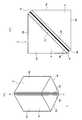
Translated fromKorean도 1은 본 발명의 실시의 형태의 편광 빔 분할기의 기본 구조의 설명도이다.BRIEF DESCRIPTION OF THE DRAWINGS It is explanatory drawing of the basic structure of the polarizing beam splitter of embodiment of this invention.
도 2는 실시의 형태의 편광 빔 분할기의 편광 분리 동작의 설명도이다.2 is an explanatory diagram of a polarization separation operation of the polarization beam splitter of the embodiment.
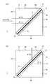
도 3은 실시의 형태의 편광 빔 분할기의 구조의 설명도이다.It is explanatory drawing of the structure of the polarizing beam splitter of embodiment.
도 4는 실시의 형태의 편광 빔 분할기의 구조의 다른 예의 설명도이다.It is explanatory drawing of the other example of the structure of the polarizing beam splitter of embodiment.
도 5는 실시의 형태의 편광 빔 분할기의 유리 프리즘 형상의 다른 예의 설명도이다.It is explanatory drawing of the other example of the glass prism shape of the polarizing beam splitter of embodiment.
도 6은 실시의 형태의 2개의 와이어 그리드 편광 분리 소자를 이용한 편광 빔 분할기의 설명도이다.6 is an explanatory diagram of a polarizing beam splitter using two wire grid polarization splitting elements of an embodiment.
도 7은 실시의 형태의 액정 투사기 장치의 광학계 예의 설명도이다.7 is an explanatory diagram of an example of an optical system of the liquid crystal projector apparatus of the embodiment.
도 8은 실시의 형태의 액정 투사기 장치의 광학계 예의 설명도이다.8 is an explanatory diagram of an example of an optical system of the liquid crystal projector apparatus of the embodiment.
도 9는 실시의 형태의 액정 투사기 장치의 광학계 예의 설명도이다.9 is an explanatory diagram of an example of an optical system of the liquid crystal projector apparatus of the embodiment.
도 10은 실시의 형태의 액정 투사기 장치의 광학계 예의 설명도이다.10 is an explanatory diagram of an example of an optical system of the liquid crystal projector apparatus of the embodiment.
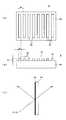
도 11은 와이어 그리드 편광 분리 소자의 설명도이다.11 is an explanatory diagram of a wire grid polarization splitting element.
도 12는 종래의 액정 투사기 장치의 광학계의 설명도이다.It is explanatory drawing of the optical system of the conventional liquid crystal projector device.
*부호에 대한 설명* Description of the sign
1, 1R, 1G, 1B. 편광 빔 분할기2, 3. 유리 프리즘1, 1R, 1G, 1B. Polarizing beam splitter 2, 3. glass prism
4. 와이어 그리드 편광 분리 소자4a. 금속 격자 구조면4. Wire grid
6. 에어갭7. 고정 플레이트6. Air gap 7. Fixed plate
8. 스페이서13, 13R, 13G, 13B. 반사형 액정 패널8.
14. 투영 렌즈15. 색합성 프리즘14.
16, 17. 다이크로익 미러16, 17. Dichroic Mirror
본 발명은 입사광을 직교하는 2개의 직선 편광으로 나누고, 1개의 편광은 투과하여 출사하고, 또 하나의 편광은 반사시키는 것으로 편광 분리를 실시하며, 편광 빔 분할기 및 이 편광 빔 분할기 이용한 액정 투사기 장치에 관한 것이다.The present invention divides incident light into two orthogonal linearly polarized light, transmits one polarized light and emits it, and reflects another polarized light to perform polarized light separation, and to a polarizing beam splitter and a liquid crystal projector using the polarizing beam splitter. It is about.
[특허 문헌 1]특개 2003-131212호 공보[Patent Document 1] Japanese Patent Application Laid-Open No. 2003-131212
반사형 액정 패널을 이용한 반사형 액정 투사기 장치에서는, 액정 패널의 광의 입사부와 출사부가 동일하기 때문에, 편광 빔 분할기 등으로 편광 분리를 실시하는 것이 필요하다.In the reflection type liquid crystal projector device using the reflection type liquid crystal panel, since the incidence part and the exit part of the light of the liquid crystal panel are the same, it is necessary to perform polarization separation with a polarization beam splitter or the like.
도 12a에 반사형 액정 투사기 장치의 기본 광학계를 도시한다.12A shows a basic optical system of the reflection type liquid crystal projector device.
광원(방전 램프)(102)으로부터 출사되는 광은 반사경(106)에 의해 집광되고, 대략 평행광의 광속으로 이루어진다. 그리고, 조명 광학계(103) 및 편광 분리 소자로서의 편광 빔 분할기(101)를 거쳐서 반사형 액정 패널(104)에 집광 조명한 다.Light emitted from the light source (discharge lamp) 102 is collected by the
반사형 액정 패널(104)의 앞에 배치되는 편광 빔 분할기(101)는 도 12b에 도시된 바와 같이, S편광(편광 빔 분할기의 편광 분리면에 대하여)을 반사하고, P편광을 투과시킨다. 따라서, 도 12a의 경우, P편광 성분이 반사형 액정 패널(104)에 입사하게 된다.The
반사형 액정 패널(104)에는 영상 신호(Sv)가 인가된다. 인가되는 영상 신호(Sv)에 따라, 반사형 액정 패널(104)은 내부의 액정에 전계를 인가한다. 액정 분자의 배열은 인가 전계에 의해 변화한다. 이 액정 분자의 배열에 의해, 선광성(旋光性) 때문에, 입사광은 편광 회전하여 출사된다.The image signal S ′ is applied to the reflective
이 패널 출사광은 영상 신호(Sv)에 따른 광학상으로 되지만, 재차 편광 빔 분할기(101)로 입사한다. 반사형 액정 패널(104)에 의해, 편광의 진동 방향이 회전된 S편광(편광 빔 분할기의 편광 분리면에 대하여)만이 편광 빔 분할기(104)의 편광 분리면에서 반사하고, 투영 렌즈(105)로 향한다.This panel exiting light becomes an optical image according to the video signal S ', but again enters the
투영 렌즈(105)는 반사형 액정 패널(104)로 형성되는 광학상을 투영 출력한다. 이것에 의해 영상이 투영 표시된다.The projection lens 105 projects and outputs an optical image formed of the reflective
여기서 편광 빔 분할기(101), 삼각기둥의 유리 프리즘을 대응하게 한 것이다. 대응면에는, 다층의 광학 박막이 증착되어 적층되고 있고, 편광 분리를 실시한다 .Here, the polarizing
그런데 이와 같은, 유리 프리즘을 이용한 편광 빔 분할기는 편광 분리 특성 (P편광과 S편광의 투과·혹은 반사의 소광비(消光比)) 좋게 하는데에는 , F 넘버의 큰 광, 즉 평행광에 가까운 광을 입사시킬 필요가 있다.However, such a polarizing beam splitter using a glass prism has a good polarization separation characteristic (the extinction ratio of the transmission and / or reflection of P-polarized light and S-polarized light). It is necessary to make it incident.
그래서, 편광 분리 특성을 향상시키는 제안이 여러 가지 되어오고 있지만, 그 안의 하나로서 상기 특허 문헌 1에 기재되어 나타낸 바와 같이, 와이어 그리드(wire grid)를 이용한 편광 분리 소자를 삼각기둥 유리 프리즘으로 사이에 두는 구조가 있다.Therefore, various proposals for improving polarization separation characteristics have been made, but as one of them, as described in
와이어 그리드 편광 분리 소자의 구조를 도 11a 및 도 11b에 도시한다.The structure of the wire grid polarization splitting element is shown in Figs. 11A and 11B.
와이어 그리드 편광 분리 소자(4)는 유리 기판(4b)의 한쪽 면(4a)(금속 격자 구조면(4a))에, 알루미늄 등의 금속으로 평행한 줄무늬 모양의 금속 격자(4c)를 형성한 것이다.The wire grid
도시한 바와 같이, 금속 격자(4c)를 형성하는 개개의 금속 스트라이프(stripe)의 폭을 w, 높이를 h로 하고, 또 격자의 형성 주기(피치(pitch))를 p로 했을 때, 입사광의 파장에 대하여 약 1/5 이하의 충분히 작은 주기(p)로 금속 격자(4c)를 형성하면, 주기 방향과 수직에 진동하는 전계 성분의 광은 반사하고, 또 평행으로 진동하는 전계 성분의 광은 투과하여, 거의 광흡수가 없고, 효율적으로 편광 분리할 수 있다.As shown, when the width of each metal stripe forming the
이 때문에 도 11c에 도시된 바와 같이, 자연광이 어떤 입사각으로 입사했을 때, 반사하는 광은 와이어 그리드 편광 분리 소자(4)의 입사면에 대하여 S편광, 투과하는 광은 상기 입사면에 대하여 P편광으로 이루어진다.For this reason, as shown in Fig. 11C, when natural light is incident at a certain incident angle, the reflected light is S-polarized with respect to the incident surface of the wire grid
이와 같은 와이어 그리드 편광 분리 소자(4)는 편광 분리 특성이 좋고, 또 입사각에 대하여 분광 투과율의 변화가 작다고 하는 이점을 가지는 것이 알려져 있 다.It is known that such a wire grid
상기 특허 문헌 1에 기재된 편광 분리 소자는 삼각기둥의 유리 프리즘에 와이어 그리드 편광 분리 소자를 사이에 두는 것으로, 편광 분리 특성이 좋은 편광 빔 분할기를 구성하는 것이 기재되어 있다.The polarization splitting device described in
그렇지만, 상기 특허 문헌 1의 편광 빔 분할기에는, 이하와 같은 문제가 있다 .However, the polarizing beam splitter of
우선, 소기의 편광 분리 성능을 내는 것이 곤란하다는 것을 들 수 있다.First, it is mentioned that it is difficult to give a desired polarization separation performance.
상기 특허 문헌 1의 기재에 의하면, 와이어 그리드 편광 분리 소자를 삼각기둥 프리즘에 접착하여 사이에 두는 것으로, 일체화된다. 그런데 와이어 그리드 편광 분리 소자는 상기와 같이 미소한 금속에 평행으로 줄무늬의 금속 격자(4c)를 형성한 것이다. 금속 격자(4c)의 높이는 100 ~ 200 nm정도로, 금속 격자(4c)의 폭은 50 ~ 100 nm정도이다 .According to the description of
이러한 금속 격자가 형성된 면에 삼각기둥 프리즘을 접착하면, 접착제에 의해, 격자가 파괴되어 버리고, 소망하는 편광 분리 성능이 발휘되지 않는 것이 많다.When a triangular prism is adhere | attached on the surface in which such a metal lattice was formed, in many cases, a lattice will be destroyed by an adhesive agent and a desired polarization separation performance will not be exhibited.
또, 금속 격자가 파괴되지 않았다고 해도, 다음과 같은 문제가 있다.In addition, even if the metal lattice is not destroyed, there are the following problems.
와이어 그리드 기판의 반대측, 즉 금속 격자면측은, 굴절률이 1이 아니면 소망한 성능이 발휘하기 어렵다. 굴절률 1은 공기이기 때문에, 삼각기둥 프리즘에 끼워 접착하는 것은, 충분한 성능이 발휘되지 않는다.If the refractive index is not 1, the opposite side of the wire grid substrate, that is, the metal lattice surface side, is unlikely to exhibit the desired performance. Since the
이상, 와이어 그리드 편광 분리 소자를 이용한 편광 빔 분할기로서, 상기 문제를 해소하고, 고성능인 편광 빔 분할기를 제공하는 것 및 그 편광 빔 분할기를 이용하여 고성능인 액정 투사기 장치를 실현하는 것이 요망되고 있다.As described above, it is desired to solve the above problems as a polarization beam splitter using a wire grid polarization splitting element, to provide a high performance polarization beam splitter, and to realize a high performance liquid crystal projector using the polarization beam splitter.
본 발명의 일실시의 형태인 편광 빔 분할기는 기둥 모양체의 측면으로서, 광의 입사면 또는 출사면으로 이루어지는 제 1 및 제 2의 단면과, 대향면을 가지는 제 1의 유리 프리즘과, 기둥 모양체의 측면으로서, 광의 입사면 또는 출사면으로 이루어진 제 1 및 제 2의 단면과, 대향면을 가지는 제 2의 유리 프리즘과, 유리 기판의 한쪽의 면에 금속 격자가 형성되어 이루어지는 와이어 그리드 편광 분리 소자를 가진다. 그리고, 상기 와이어 그리드 편광 분리 소자는, 상기 유리 기판의 상기 금속 격자가 형성되어 있지 않은 쪽의 면이, 상기 제 1의 유리 프리즘의 상기 대향면에 고착되고, 상기 제 2의 유리 프리즘은, 그 대향면이, 공기층을 형성하는 상태로, 상기 와이어 그리드 편광 분리 소자가 고착된 상기 제 1의 유리 프리즘의 상기 대향면에 대향하도록 배치되어 이루어진다.The polarizing beam splitter according to the embodiment of the present invention is a side surface of a columnar body, which includes first and second cross sections formed of an incident surface or an exit surface of light, a first glass prism having an opposing surface, and a side surface of the columnar body. It has a 1st and 2nd cross section which consists of an incident surface or an emitting surface of light, the 2nd glass prism which has an opposing surface, and the wire grid polarization splitting element in which the metal grating is formed in one surface of a glass substrate. . And as for the said wire grid polarization splitting element, the surface in which the said metal grating | lattice of the said glass substrate is not formed is stuck to the said opposing surface of the said 1st glass prism, and the said 2nd glass prism is the The opposing surface is disposed so as to face the opposing surface of the first glass prism to which the wire grid polarization splitting element is fixed, in a state of forming an air layer.
또 상기 제 1 및 제 2의 유리 프리즘은, 그 기둥 모양체의 상면과 하면이 고정 플레이트에 고착되는 것으로, 상기 대향면끼리가 상기 공기층을 형성하면서 고정 배치되는 구조를 실현한다.In the first and second glass prisms, the upper surface and the lower surface of the columnar body are fixed to the fixing plate, thereby realizing a structure in which the opposing surfaces are fixedly arranged while forming the air layer.
혹은, 상기 제 1 및 제 2의 유리 프리즘은, 상기 대향면의 단부 혹은 상기 대향면에 고착된 상기 와이어 그리드 편광 분리 소자의 단부가 스페이서(spacer)에 고착되는 것으로, 상기 대향면끼리가 상기 공기층을 형성하면서 고정 배치되는 구 조를 실현한다.Alternatively, in the first and second glass prisms, an end portion of the opposing surface or an end portion of the wire grid polarization splitting element fixed to the opposing surface is fixed to a spacer, and the opposing surfaces are the air layer. It achieves a structure that is fixedly arranged while forming a.
또, 유리 기판의 한쪽 면에 금속 격자가 형성되어 이루어지는 제 2의 와이어 그리드 편광 분리 소자를 또한 구비하고, 상기 제 2의 와이어 그리드 편광 분리 소자는, 상기 유리 기판의 상기 금속 격자가 형성되어 있지 않은 쪽의 면이, 상기 제 2의 유리 프리즘의 상기 대향면에 고착된다.In addition, a second wire grid polarization splitting element in which a metal lattice is formed on one surface of the glass substrate is further provided, and the second wire grid polarization splitting element is not provided with the metal lattice of the glass substrate. The side of the side is fixed to the opposing surface of the second glass prism.
본 발명의 일실시의 형태인 액정 투사기 장치는, 광원과 영상 신호에 따라 광학상을 형성하는 반사형 액정 패널과, 투영 렌즈와, 상기 광원으로부터 소정의 광경로로 유도된 광을 편광 분리하여 상기 반사형 액정 소자에 유도하고, 또 상기 반사형 액정 소자에서 반사된 광을 편광 분리하여 상기 투영 렌즈 측으로 유도되는 편광 빔 분할기를 구비한다. 그리고, 상기 편광 빔 분할기는, 기둥 모양체의 측면으로서, 광의 입사면 또는 출사면으로 이루어지는 제 1 및 제 2의 단면과, 대향면을 가지는 제 1의 유리 프리즘과, 기둥 모양체의 측면으로서, 광의 입사면 또는 출사면으로 이루어지는 제 1 및 제 2의 단면과, 대향면을 가지는 제 2의 유리 프리즘과, 유리 기판의 한쪽 면에 금속 격자가 형성되어 이루어지는 와이어 그리드 편광 분리 소자를 가지고, 상기 와이어 그리드 편광 분리 소자는, 상기 유리 기판의 상기 금속 격자가 형성되어 있지 않은 쪽의 면이, 상기 제 1의 유리 프리즘의 상기 대향면에 고착되고, 상기 제 2의 유리 프리즘은, 그 대향면이, 공기층을 형성하는 상태로, 상기 와이어 그리드 편광 분리 소자가 고착된 상기 제 1의 유리 프리즘의 상기 대향면에 대향하도록 배치되어 이루어진다.A liquid crystal projector device according to one embodiment of the present invention comprises a reflective liquid crystal panel that forms an optical image in accordance with a light source and an image signal, a projection lens, and polarized light separation of light guided by a predetermined optical path from the light source. And a polarizing beam splitter which is guided to the reflective liquid crystal device and is directed to the projection lens side by polarizing separation of the light reflected by the reflective liquid crystal device. The polarizing beam splitter includes, as side surfaces of the columnar body, first and second end surfaces formed of the incident surface or the exit surface of the light, a first glass prism having an opposing surface, and a side surface of the columnar body. And a wire grid polarized light separating element in which a metal lattice is formed on one surface of a glass substrate, and a second glass prism having an opposing surface, and a first and a second cross section composed of a plane or an emission plane. In the separation element, the surface of the glass substrate on which the metal lattice is not formed is fixed to the opposing surface of the first glass prism, and the opposing surface of the second glass prism is an air layer. In the forming state, the wire grid polarization splitting element is disposed so as to face the opposing surface of the first glass prism to which it is fixed.
또, 상기 소정의 광경로로서, 상기 광원으로부터의 백색광을, R광, G광, B광 으로 분리하는 분리 광학 수단을 구비한다. 상기 반사형 액정 패널로서 R, G, B 각 색의 영상 신호에 따라 광학상을 형성하는 제 1, 제 2 및 제 3의 반사형 액정 패널을 구비한다. 상기 편광 빔 분할기로서, 상기 분리 광학 수단으로 분리된 R광, G광, B광 및 상기 제 1, 제 2 및 제 3의 반사형 액정 패널에 각각 대응하는 제 1, 제 2 및 제 3의 편광 빔 분할기를 구비한다. 또한, 상기 제 1, 제 2 및 제 3의 반사형 액정 패널에서 반사되고, 상기 제 1, 제 2 및 제 3의 편광 빔 분할기에서 편광 분리된 R, G, B 각 색의 광을 합성하여 상기 투영 렌즈로 유도되는 광합성 수단을 구비하는 것으로 칼라 표시를 실시하는 액정 투사기 장치를 구성한다.Further, as the predetermined light path, separation optical means for separating white light from the light source into R light, G light, and B light is provided. The said reflective liquid crystal panel is provided with the 1st, 2nd, and 3rd reflective liquid crystal panel which forms an optical image according to the image signal of each of R, G, and B colors. As said polarizing beam splitter, first, second and third polarized light corresponding to R light, G light, B light and said first, second and third reflective liquid crystal panels respectively separated by said separating optical means; And a beam splitter. In addition, the light of each of R, G, and B colors reflected by the first, second and third reflective liquid crystal panels and polarized and separated by the first, second and third polarization beam splitters may be synthesized. By providing photosynthesis means guided to the projection lens, a liquid crystal projector device for color display is constituted.
이러한 액정 투사기 장치에 있어서, 편광 빔 분할기는, 상기 제 1 및 제 2의 유리 프리즘이, 그 기둥 모양체의 상면과 하면이 고정 플레이트에 고착되는 것으로, 상기 대향면끼리가 상기 공기층을 형성하면서 고정 배치된다.In such a liquid crystal projector apparatus, the polarizing beam splitter is configured such that the upper and lower surfaces of the first and second glass prisms are fixed to the fixing plate, and the opposing surfaces are fixed while the air layers are formed. do.
혹은, 상기 편광 빔 분할기에 있어서의 상기 제 1 및 제 2의 유리 프리즘은, 상기 대향면의 단부 혹은 상기 대향면에 고착된 상기 와이어 그리드 편광 분리 소자의 단부가 스페이서에 고착되는 것으로, 상기 대향면끼리가 상기 공기층을 형성하면서 고정 배치된다.Alternatively, in the first and second glass prisms in the polarizing beam splitter, an end of the opposing surface or an end of the wire grid polarization splitting element fixed to the opposing surface is fixed to a spacer. The two are fixedly arranged while forming the air layer.
또 상기 편광 빔 분할기는, 유리 기판의 한쪽 면에 금속 격자가 형성되어 이루어지는 제 2의 와이어 그리드 편광 분리 소자를 또한 구비하고, 상기 제 2의 와이어 그리드 편광 분리 소자는, 상기 유리 기판의 상기 금속 격자가 형성되어 있지 않은 쪽의 면이, 상기 제 2의 유리 프리즘의 상기 대향면에 고착된다.The polarizing beam splitter further includes a second wire grid polarization splitting element in which a metal lattice is formed on one surface of the glass substrate, and the second wire grid polarization splitting element is the metal lattice of the glass substrate. The surface on which the side is not formed is fixed to the opposite surface of the second glass prism.
즉, 와이어 그리드 편광 분리 소자와 제 1 및 제 2의 유리 프리즘에 의해 편 광 빔 분할기를 구성하지만, 와이어 그리드 편광 분리 소자는, 그 유리 기판의 금속 격자가 형성되어 있지 않은 면이, 한쪽의 유리 프리즘에 고착된다. 그리고, 금속 격자측은 한쪽의 유리 프리즘 측에 대하여 공기층을 거쳐서 대향한다. 즉, 금속 격자측은 한쪽의 유리 프리즘 측에 접촉하지 않게 된다.That is, although the polarization beam splitter is constituted by the wire grid polarization splitting element and the first and second glass prisms, the surface of the wire grid polarization splitting element on which the metal lattice of the glass substrate is not formed is one glass. Sticks to the prism The metal lattice side faces one glass prism side via an air layer. In other words, the metal lattice side is not in contact with one glass prism side.
이하, 본 발명의 편광 빔 분할기 및 그것을 이용한 액정 투사기 장치의 각종 실시의 형태를 설명하고 있다.Hereinafter, various embodiments of the polarizing beam splitter of the present invention and the liquid crystal projector apparatus using the same are described.
<편광 빔 분할기><Polarization beam splitter>
우선, 도 1, 도 2에서 실시의 형태의 편광 빔 분할기의 기본 구성을 설명한다.First, the basic structure of the polarizing beam splitter of embodiment of FIG. 1, FIG. 2 is demonstrated.
도 1a 및 도 1b에 도시된 바와 같이, 본 예의 편광 빔 분할기(1)는 삼각기둥 형상의 유리 프리즘(2, 3)과, 와이어 그리드 편광 분리 소자(4)를 가지고 이루어진다.As shown in Figs. 1A and 1B, the
유리 프리즘(2)은 그 삼각기둥 형상으로서 3개의 측면(2a, 2b, 2c)을 가지지만, 측면(2a, 2b)은 광학 경로상에 편광 빔 분할기(1)가 배치되었을 때에 입사면 또는 출사면으로 이루어지는 면이다.The
측면(2c)은 한쪽의 유리 프리즘(3)에 대향하는 대향면으로 이루어진다.
유리 프리즘(3)도 동일하게 그 삼각기둥 형상으로서 3개의 측면(3a, 3b, 3c)을 가지지만, 측면(3a, 3b)은 광학 경로상에 편광 빔 분할기(1)가 배치되었을 때에 입사면 또는 출사면으로 이루어지고, 측면(3c)은 유리 프리즘(2)에 대향하는 대향면으로 이루어진다.The
이하, 설명상, 측면(2a, 2b, 3a, 3b)은 형성되는 광로에 따라 입사면 또는 출사면으로 불리고, 측면(2c, 3 c)은 대향면으로 불린다.In the following description, the side surfaces 2a, 2b, 3a, and 3b are referred to as entrance or exit surfaces according to the optical paths formed, and the side surfaces 2c and 3c are called opposing surfaces.
와이어 그리드 편광 분리 소자(4)는 먼저 도 11에서 상술한 구조이며, 즉 유리 기판(4b)의 한쪽 면에 금속 격자(4c)가 소정 피치로 설치되고, 금속 격자 구조면(4a)이 형성되는 구조로 이루어진다.The wire grid
그리고, 도 1에 도시된 바와 같이, 편광 빔 분할기(1)는 2개의 삼각기둥의 유리 프리즘(2, 3)의 사이에 와이어 그리드 와이어 그리드 편광 분리 소자(4)를 배치한다.1, the
이 때, 와이어 그리드 편광 분리 소자(4)의 유리 기판(4b)은 접착제에 의해 유리 프리즘(2)의 대향면(2c)에 접착 고정된다.At this time, the
한편, 와이어 그리드 편광 분리 소자(4)의 금속 격자 구조면(4a)은 다른 쪽의 유리 프리즘(3)의 대향면(3c)에 대하여, 에어갭(공기층)(6)을 거쳐서 대향하는 상태로 이루어진다. 즉, 금속 격자 구조면(4a)측은 접착되지 않는다.On the other hand, the metal
이와 같이 유리 프리즘(2, 3)간에 에어갭(6)과 와이어 그리드 편광 분리 소자(4)가 배치된 편광 빔 분할기(1)의 동작을 도 2에서 설명한다.The operation of the
도 2a에 도시된 바와 같이, 유리 프리즘(2)의 입사면(2a)으로부터 광이 입사된다고 한다. 입사광은 P편광과 S편광을 가진다.As shown in FIG. 2A, it is assumed that light is incident from the
입사광은 우선, 유리 프리즘(2)에 입사하고, 다음에, 유리 프리즘(2)과 와이어 그리드 편광 분리 소자(4)의 접착면에 입사한다. 다음에, 와이어 그리드 편광 분리 소자(4)의 금속 격자 구조면(4a)에 광이 입사하지만, 금속 격자 구조면 (4a)에 대하여 S편광은 반사하고, P편광은 투과한다.The incident light first enters the
그 후, 도 2b에 도시된 바와 같이, S편광은 다시 유리 프리즘(2)에 들어가고, 출사면(2b)에서 출사된다. 한쪽 P편광은 에어갭(6)에 입사한 후, 다른 쪽의 유리 프리즘(3)에 들어간다. 그리고 유리 프리즘(3)에 입사 후, 이것을 투과하고, 출사면(3a)에서 출사된다.Thereafter, as shown in FIG. 2B, the S-polarized light enters the
이러한 편광 빔 분할기(1)의 경우, 와이어 그리드 편광 분리 소자(4)가 유리 프리즘(2, 3)에 끼워지는 위치에 배치되지만, 금속 격자 구조면(4a)측은 에어갭(6)이 형성되는 구조로 이루어져서, 금속 격자 구조면(4a)을 접착제로 유리 프리즘(3)에 접착하지 않기 때문에, 금속 격자(4c)가 접착제에 의해 파괴되어 버리는 것이 일어나지 않는다. 또, 금속 격자 구조면(4a)측은 굴절률이 1인 에어갭(6)으로 이루어지기 때문에, 와이어 그리드 편광 분리 소자(4)로서의 본래의 편광 분리 성능을 발휘할 수 있다. 따라서, 고성능의 편광 빔 분할기를 실현할 수 있다.In the case of such a
도 1에서 설명한 바와 같이, 유리 프리즘(2, 3)의 사이에 에어갭(6)을 형성한 상태로 와이어 그리드 편광 분리 소자(4)를 배치하기 위한 구조예를 도 3, 도 4에서 설명한다.As illustrated in FIG. 1, structural examples for arranging the wire grid
도 3은 고정 플레이트(7)를 이용하는 예이다.3 shows an example using the fixing plate 7.
도면과 같이, 유리 프리즘(2, 3)의 상면 및 하면을 고정 플레이트(7, 7)로 접착 고정된다.As shown in the figure, the upper and lower surfaces of the
이와 같이, 고정 플레이트(7, 7)로 유리 프리즘(2, 3)을 고정하는 것으로, 상기와 같이 에어갭(6)을 형성한 편광 빔 분할기(1)를 실현할 수 있다. 고정 플 레이트(7)의 사이즈나 형상은 한정되지 않고, 유리 프리즘(2, 3)의 상면 및 하면을 고정할 수 있는 것이면 좋다.As described above, by fixing the
도 4는 스페이서(8)를 이용하는 예이다.4 shows an example of using the spacer 8.
도면과 같이, 유리 프리즘(2)의 대향면(2c)상에 접착된 와이어 그리드 편광 분리 소자(4)의 금속 격자 구조면(4a)의 단부와 유리 프리즘(3)의 대향면(3c)의 단부를, 스페이서(8, 8)를 개재시키는 상태로 접착 고정한다.As shown in the figure, the end of the metal
물론 스페이서(8)를 접착하는 단부란, 금속 격자 구조면(4a)상에서 광이 입사하지 않는 부위로 한다.Of course, the end portion to which the spacer 8 is bonded is a portion where light does not enter on the metal
스페이서(8)는 대향면(3c)에 대하여, 그 면의 4변상에서 둘러싸도록 형성하여도 좋고, 적어도 2변에 설치되어도 좋다.The spacer 8 may be formed so as to surround the opposing
예를 들면, 이상의 도 3 또는 도 4와 같이 구성하는 것으로, 본 예의 빔 분할기(1)를 실현할 수 있다.For example, the
또한, 도 4와 같이 스페이서(8)를 이용한 후에, 또한, 유리 프리즘(2, 3)의 상면 및 하면을 고정 플레이트(7)로 고정하는 구조여도 좋다.Moreover, after using the spacer 8 like FIG. 4, the structure which fixes the upper surface and lower surface of the
도 5는 편광 빔 분할기(1)의 다른 구성예를 나타내고 있다.5 shows another configuration example of the
상기 도 1 ~ 도 4에 설명한 편광 빔 분할기(1)는 와이어 그리드 편광 분리 소자(4)의 금속 격자 구조면(4a)에의 입사각도가 45도로 되는 구조예로 설명하고 있었지만, 도 5에 도시된 바와 같이 입사각도가 45도로부터 벗어나는 구조도 고려할 수 있다.Although the
도 5a는 입사각(θ)이 45도보다 커지게 되는 구조예, 도 5(b)는 입사각(θ) 이 45도보다 작게 되는 구조예를 각각 나타내고 있다.5A shows a structural example in which the incident angle θ becomes larger than 45 degrees, and FIG. 5B shows a structural example in which the incident angle θ becomes smaller than 45 degrees.
즉, 유리 프리즘(2, 3)으로서의 삼각기둥의 단면 형상은 임의이며, 필요한 광로나 입사각을 형성하기 위해서 필요한 형상으로 이루어지면 좋다.That is, the cross-sectional shape of the triangular prism as the
또한, 와이어 그리드 편광 분리 소자(4)는 입사각도에 대하여 P/S분광 분리 특성이 대부분 변화하지 않는다고 하는 특성을 가지기 때문에, 편광 빔 분할기(1)에 요구되는 입사 광로, 출사 광로에 따라 유리 프리즘(2, 3)의 형상을 결정해도, 분리 특성이 악화되지 않는다.In addition, since the wire grid
도 6은 와이어 그리드 편광 분리 소자(4)를 2개 설치한 구성예이다.6 is a configuration example in which two wire grid
즉, 도 6a에 도시된 바와 같이, 유리 프리즘(2)의 대향면(2c)에 와이어 그리드 편광 분리 소자(4)가 접착되는 것과 동시에, 유리 프리즘(3)의 대향면(3c)에도 와이어 그리드 편광 분리 소자(4)가 접착된다. 그리고, 상대하는 와이어 그리드 편광 분리 소자(4, 4)의 사이(금속 격자 구조면(4a), 4 a간)는 에어갭(6)이 형성된다.That is, as shown in FIG. 6A, the wire grid
이 때, 각 와이어 그리드 편광 분리 소자(4, 4)의 금속 격자(4c)의 홈 방향을 동일하게 한다 .At this time, the groove direction of the
또한, 이 도 6a와 같은 배치의 편광 빔 분할기(1)도, 도 3과 같이 고정 플레이트(7)를 이용하거나, 도 4와 같이 스페이서(8)를 이용하는 것으로 실현될 수 있다.In addition, the
이 도 6a와 같이, 와이어 그리드 편광 분리 소자(4)를 2개 배치하는 것으로, 편광 분리 특성을 또한 향상시킬 수 있다. 즉, 도 6b에 도시된 바와 같이, 예를 들면 입사면(2a)으로부터 입사된 광은 우선, 유리 프리즘(2)에 접착된 와이어 그리드 편광 분리 소자(4)의 금속 격자 구조면(4a)에서 S편광이 반사되고, P편광이 투과되지만, 얼마 안되는 S편광 성분은 투과하여 버린다. 그 투과한 S편광 성분도, 다음에 유리 프리즘(3) 측에 접착된 와이어 그리드 편광 분리 소자(4)의 금속 격자 구조면(4a)으로 입사하기 때문에, 파선에서 나타낸 바와 같이 반사된다.As shown in FIG. 6A, by arranging two wire grid
즉, 2개의 와이어 그리드 편광 분리 소자(4, 4)에서 편광 선택을 2회 실시하는 것으로, 편광 분리 특성을 향상시킬 수 있다.That is, polarization separation characteristics can be improved by performing polarization selection twice in the two wire grid
이상, 편광 빔 분할기(1)의 각종 구성예를 상술했지만, 실제의 구성예는 또한 다양하게 생각된다.As mentioned above, although the various structural examples of the
편광 빔 분할기(1)에 이용하는 와이어 그리드 편광 분리 소자(4)는 금속 격자(4c)의 주기를 120 nm이하, 금속 격자(4c)의 높이를 180 nm정도로 하는 것이 바람직하다.In the wire grid
또, 유리 프리즘(2, 3)은 반드시 삼각기둥 프리즘일 필요는 없다. 물론 , 삼각기둥이어도 모서리가 둥그스름하게 이루어진 것으로, 정확하게 삼각기둥이 아니게 되는 경우도 있고, 혹은 4각기둥 이상의 다각기둥 형상으로 되는 경우도 생각할 수 있다. 어디까지나, 편광 빔 분할기(1)에 요구되는 편광 광로 형성에 요구되는 형상으로 이루어지면 좋다.In addition, the
또 유리 프리즘(2, 3)은 부재(部材) 유리의 광탄성 계수가 0.5×10⁻⁸[cm2/N] 이하이고, 유리의 복굴절의 영향을 받지 않는다.In addition, the
또 유리 프리즘(2, 3)의 입사면/출사면(2a, 2b, 3a, 3b)에 계면반사를 감소시키기 위한 코팅을 실시하는 것 등도 생각할 수 있다.In addition, it is also conceivable to apply a coating for reducing interfacial reflection to the entrance /
<반사형 액정 투사기 장치><Reflection type liquid crystal projector device>
연속하여, 상술해 온 편광 빔 분할기(1)를 이용한 반사형 액정 투사기 장치의 광학계의 구성예를 설명한다.Next, the structural example of the optical system of the reflection type liquid crystal projector device using the above-mentioned
도 7은 반사형 액정 패널(13)에 P편광이 입사하는 예로서 광학계의 기본 구성을 나타내고 있다. 편광 빔 분할기(1)는 유리 프리즘(2) 측에 와이어 그리드 편광 분리 소자(4)가 접착되어 있는 구조로 하고 있다.7 illustrates the basic configuration of an optical system as an example in which P-polarized light is incident on the reflective
광원(방전 램프)(10)으로부터 출사되는 광은 반사경(11)에 의해 집광되고, 대략 평행광의 광속으로 이루어진다. 그리고, 조명 광학계(12)를 거쳐서 편광 빔 분할기(1)의 입사면(3a)에 입사된다. 그리고, 입사면(3a)으로부터 편광 빔 분할기(1)의 유리 프리즘(3)에 입사한 광은 대향면(3c)으로부터 에어갭(6)에 도달하고, 그 후 와이어 그리드 편광 분리 소자(4)의 금속 격자 구조면(4a)에서 편광 분리되는 것으로, P편광만이 유리 프리즘(2) 측에 입사한다. 그리고, 그 P편광은 출사면(2a)으로부터 출사되어 반사형 액정 패널(13)에 집광 조명한다.The light emitted from the light source (discharge lamp) 10 is collected by the
반사형 액정 패널(13)에는 영상 신호(Sv)가 인가된다.The image signal S ′ is applied to the reflective
인가되는 영상 신호(Sv)에 따라 , 반사형 액정 패널(13)은 내부의 액정에 전계를 인가한다. 액정 분자의 배열은 인가 전계에 의해 변화한다. 이 액정 분자의 배열에 의해, 광학활성이기 때문에, 입사광은 편광 회전하여 출사된다.In response to the applied image signal S \, the reflective
이 패널 출사광의 S편광은 영상 신호(Sv)에 따른 광학상으로 되지만, 재차 편광 빔 분할기(1)에 입사면(2a)으로부터 입사한다. 그리고, 유리 프리즘(2)을 통과하여 와이어 그리드 편광 분리 소자(4)의 금속 격자 구조면(4a)에 도달하고, 여기서 S편광만이 반사되어 출사면(2b)으로부터 투영 렌즈(14)로 향한다.The S-polarized light of the panel output light becomes an optical image according to the video signal S ', but again enters the
투영 렌즈(14)는 반사형 액정 패널(13)에서 형성된 광학상을 투영 출력한다. 이것에 의해 영상이 확대 투영 표시된다.The
이 경우, 패널 출사광은 편광 빔 분할기(1)의 에어갭(6)을 통과하지 않고 투영 렌즈(14)에 의해 확대 투영되기 때문에, 에어갭(6)의 통과에 수반하는 비점수차가 발생하지 않고, 양호한 투영상을 얻을 수 있다.In this case, since the panel exit light is projected by the
다음에 도 8은 반사형 액정 패널(13)에 S편광이 입사하는 예로서 광학계의 기본 구성을 나타내고 있다. 상기 도 7과 동일하게, 편광 빔 분할기(1)는 유리 프리즘(2) 측에 와이어 그리드 편광 분리 소자(4)가 접착되고 있는 구조로 하고 있다.8 shows the basic configuration of the optical system as an example in which S-polarized light is incident on the reflective
광원(10)으로부터 출사되는 광은 반사경(11)에 의해 집광되고, 대략 평행광의 광속으로 되며, 조명 광학계(12)를 거쳐서 편광 빔 분할기(1)의 입사면(2a)에 입사된다.Light emitted from the
그리고, 입사면(2a)으로부터 편광 빔 분할기(1)의 유리 프리즘(2)에 입사한 광은 와이어 그리드 편광 분리 소자(4)의 금속 격자 구조면(4a)에서 편광 분리되는 것으로, P편광은 그대로 에어갭(6)을 통하여 유리 프리즘(3) 측에 도달하고, 한쪽 S편광은 반사되어 출사면(2b)으로부터 출사되고, 반사형 액정 패널(13)에 집광 조명한다.The light incident on the
영상 신호(Sv)가 인가되어 있는 반사형 액정 패널(13)에서 편광 회전하여 출사된 패널 출사광은 재차 편광 빔 분할기(1)에 입사면(2b)으로부터 입사한다. 그리고 유리 프리즘(2)을 통과하여 와이어 그리드 편광 분리 소자(4)의 금속 격자 구조면(4a)에 도달하고, 여기서 P편광만이 투과되어 투영 렌즈(14)로 향한다. 투영 렌즈(14)는 반사형 액정 패널(13)에서 형성된 광학상을 투영 출력한다. 이것에 의해 영상이 확대 투영 표시된다.In the reflective
이와 같이 반사형 액정 패널(13)에, S편광이 입사하도록 하여도 좋다. 또한, 이 경우, 편광 빔 분할기(1)의 에어갭(6)이기 때문에, 투영 렌즈(14)에 의해서 확대 투영 될 때에 비점수차가 발생하지만, 에어갭(6)으로서의 갭(gap)의 사이즈(갭폭)를 가능한 한 작게 하는 것으로, 그 비점수차를 실용상 문제가 되지 않는 레벨로 저감할 수 있다.In this manner, the S-polarized light may be incident on the reflective
다음에 도 9에서, 편광 빔 분할기(1) 및 액정 패널(13)을, R(빨강), G(초록), B(파랑)의 각 색에 대응하여 각각 3개 이용한 반사형 액정 투사기 장치의 광학계의 예를 설명한다.Next, in Fig. 9, the
편광 빔 분할기(1R, 1G, 1B)는 상기 도 7 및 도 8의 편광 빔 분할기(1)와 동일한 구성으로 하고 있다.The
또, 액정 패널(13R, 13G, 13B)에는, 각각 R신호, G신호, B신호로서의 영상 신호가 공급되고 있다.Moreover, video signals as R signals, G signals, and B signals are supplied to the
광원(10)으로부터 출사되고, 반사경(11)에서 대략 평행광의 광속으로 되는 백색광은 렌즈(19)를 거쳐서 우선 다이크로익 미러(16)에 도달하여, 다이크로익 미 러(16)에 의해서 B광만이 투과되고, R광 및 G광은 반사된다.The white light emitted from the
R광 및 G광은 다음에 다이크로익 미러(17)에 도달하여, R광이 투과되고, G광이 반사된다.The R light and the G light then reach the
다이크로익 미러(16, 17)에서 RGB의 삼원색으로 분해된 각각의 광은 각 편광 빔 분할기(1R, 1G, 1B)에 입사한다.Each light decomposed into three primary colors of RGB in the
또, 편광 빔 분할기(1R, 1G, 1B)의 금속 격자 구조면(4a)에 대하여의 P편광이 입사하는 위치에, 반사형 액정 패널(13R, 13G, 13B)이 설치되어 있다. 즉 반사형 액정 패널(13R, 13G, 13B)에는 P편광이 입사하는 배치 상태로 된다.In addition, reflective
우선 다이크로익 미러(17)를 투과한 R광은 편광 빔 분할기(1R)에 있어서, 그 와이어 그리드 편광 분리 소자(4)에 의해 편광 분리되어, P편광만이 투과되고, 반사형 액정 패널(13R)에 입사된다. 그리고, 반사형 액정 패널(13R)은 R영상 신호의 인가에 의해서, 입사광을 변조 출사시키지만, 그 패널 출사광은 편광 빔 분할기(1R)에서 S편광이 선택되고, 색합성 프리즘(15)에 입사된다.First, the R light transmitted through the
다이크로익 미러(17)에서 반사된 G광은 편광 빔 분할기(1G)에 있어서 편광 분리되어 P편광만이 투과되고, 반사형 액정 패널(13G)에 입사된다. 그리고, 반사형 액정 패널(13G)은 G영상 신호의 인가에 의해서, 입사광을 변조 출사시키지만, 그 패널 출사광은 편광 빔 분할기(1G)로 S편광이 선택되고, 색합성 프리즘(15)에 입사된다.The G light reflected by the
다이크로익 미러(16)를 투과한 B광은 미러(18)에서 반사된 후, 편광 빔 분할기(1B)에 있어서 편광 분리되어 P편광만이 투과되고, 반사형 액정 패널(13B)에 입 사된다. 그리고 반사형 액정 패널(13B)은 B영상 신호의 인가에 의해서, 입사광을 변조 출사시키지만, 그 패널 출사광은 편광 빔 분할기(1B)에서 S편광이 선택되고, 색합성 프리즘(15)에 입사된다.The B light transmitted through the
색합성 프리즘(15)에 있어서는, 입사된 R, G, B 각 광이 합성되어 같은 방향으로 출사된다. 그리고, 투영 렌즈(14)에 의해서, 칼라 영상으로서 확대 투영되게 된다.In the
다음에 도 10도 편광 빔 분할기(1) 및 액정 패널(13)을, R(빨강), G(초록), B(파랑)의 각 색에 대응하여 각각 3개 이용한 반사형 액정 투사기 장치의 광학계의 예이지만, 이것은 액정 패널(13R, 13G, 13B)에는 S편광이 입사하는 구성으로 하고 있다.Next, FIG. 10 is an optical system of a reflective liquid crystal projector apparatus using three
광원(10), 반사경(11), 렌즈(19), 다이크로익 미러(16, 17), 미러(18)에 의한 광학계는 상기 도 9와 동일하다.The optical system by the
다이크로익 미러(16, 17)에서 RGB의 삼원색으로 분해된 각각의 광은 각 편광 빔 분할기(1R, 1G, 1B)에 입사하지만, 이 경우, 편광 빔 분할기(1R, 1G, 1B)의 금속 격자 구조면(4a)에 대하여의 S편광이 입사하는 위치에, 반사형 액정 패널(13R, 13G, 13B)이 설치되어 있다.Each light decomposed into three primary colors of RGB in the
그리고 다이크로익 미러(17)를 투과한 R광은 편광 빔 분할기(1R)에 있어서 편광 분리되고, S편광만이 반사되어 반사형 액정 패널(13R)에 입사된다. 그리고, 반사형 액정 패널(13R)은 R영상 신호의 인가에 의해서, 입사광을 변조 출사시키지만, 그 패널 출사광은 편광 빔 분할기(1R)에서 P편광이 선택되고, 색합성 프리 즘(15)에 입사된다.The R light transmitted through the
다이크로익 미러(17)에서 반사된 G광은 편광 빔 분할기(1G)에 있어서 편광 분리되고, S편광만이 반사되어 반사형 액정 패널(13G)에 입사된다. 그리고, 반사형 액정 패널(13G)은 G영상 신호의 인가에 의해서, 입사광을 변조 출사시키지만, 그 패널 출사광은 편광 빔 분할기(1G)에서 P편광이 선택되고, 색합성 프리즘(15)에 입사된다.The G light reflected by the
다이크로익 미러(16)를 투과한 B광은 미러(18)에서 반사된 후, 편광 빔 분할기(1B)에 있어서 편광 분리되고, S편광만이 반사되어 반사형 액정 패널(13B)에 입사된다. 그리고, 반사형 액정 패널(13B)은 B영상 신호의 인가에 의해서, 입사광을 변조 출사시키지만, 그 패널 출사광은 편광 빔 분할기(1B)에서 P편광이 선택되고, 색합성 프리즘(15)에 입사된다.The B light transmitted through the
색합성 프리즘(15)에 있어서는, 입사된 R, G, B 각 광이 합성되어 같은 방향으로 출사된다. 그리고 투영 렌즈(14)에 의해서, 칼라 영상으로서 확대 투영된다.In the
이 구성의 경우, 각 편광 빔 분할기(1R, 1G, 1B)에 있어서의 에어갭(6)이기 때문에, 투영 렌즈(14)에 의해서 확대 투영될 때에 비점수차가 발생한다. 이것에 의해 도 9의 구성의 경우에 비해 영상 품질은 열화 하지만, 에어갭(6)의 갭폭이 작으면 그다지 열화는 되지 않는다.In this configuration, since it is the
또, 이 도 10의 구성에서는, 반사형 액정 패널의 배치 위치, 특히 반사형 액정 패널(13R와 13B)의 배치 위치가, 투영 렌즈(14)로부터 떨어질 수 있으므로, 광 학계의 구성에 여유가 있는 이점을 가진다.In addition, in the structure of FIG. 10, since the arrangement position of the reflective liquid crystal panel, in particular, the arrangement position of the reflective
일반적으로, 투영 렌즈(14)로부터 액정 패널(13)까지의 거리를 백 포커스(back focus)라고 하고, 이 백 포커스가 짧을 정도 소형의 투영 렌즈를 사용할 수 있기 때문에 소형화나 비용 감소에 유리하다. 상기 도 9의 구성의 경우에 대해 백 포커스을 짧게 하려면 , 반사형 액정 패널(13R, 13B)을 투영 렌즈(14)에서 될 수 있도록 가까운 위치에 배치하고 싶지만, 실제의 광학계 얼라이먼트(alignment)상, 위치적으로 곤란하게 되는 경우가 있다. 이것에 대하여 도 10과 같은 구성에 의하면, 반사형 액정 패널(13R, 13B)은 투영 렌즈(14)와의 위치 관계로 얼라이먼트가 곤란하게 되는 것은 없다.In general, the distance from the
이상, 액정 투사기 장치의 광학계의 구성예를 도 7 ~ 도 10에서 설명하여 왔지만, 상술한 구성의 편광 빔 분할기(1)를 이용하는 것으로, 고성능인 편광 분리 성능을 얻을 수 있고, 이것에 의해, 고효율로 밝고, 고품질인 화상을 투영 표시하는 반사형 액정 투사기 광학계를 실현할 수 있다.As mentioned above, although the structural example of the optical system of a liquid crystal projector device was demonstrated in FIGS. 7-10, the
또, 와이어 그리드 편광 분리 소자(4)는 파장 선택성이 없다고 하는 특징도 구비하기 때문에, R 광, G광, B광에 대응하는 편광 빔 분할기(1R, 1G, 1B)로서는 공통의 편광 빔 분할기 소자를 이용할 수 있고, 그것에 의해 제조 효율이나 비용 감소 등에도 형편이 좋다 .In addition, since the wire grid
또한, 액정 투사기 장치로 이용하는 편광 빔 분할기(1, 1R, 1G, 1B)로서는, 그 광학계의 설계에 따라서, 도 1 ~ 도 6에서 설명한 각종 구성예의 것을 채용할 수 있다 .In addition, as the
따라서, 와이어 그리드 편광 분리 소자가, 제 1 및 제 2의 유리 프리즘에 끼워지는 위치에 배치되어 편광 빔 분할기를 형성하지만, 와이어 그리드 편광 분리 소자의 금속 격자면측은 공기층(에어갭)이 형성되는 구조로 된다. 즉, 금속 격자측을 접착제로 유리 프리즘에 접착하는 것은 아니기 때문에, 금속 격자가 접착제에 의해 파괴되어 버리는 것은 일어날 수 없다.Therefore, the wire grid polarization splitting element is disposed at a position to be fitted to the first and second glass prisms to form a polarization beam splitter, but the metal grid surface side of the wire grid polarization splitting element is formed with an air layer (air gap). It becomes That is, since the metal lattice side is not bonded to the glass prism with an adhesive, it is impossible to break the metal lattice with the adhesive.
또는, 금속 격자면측은 굴절률이 1인 공기층으로 이루어지기 때문에, 와이어 그리드 편광 분리 소자로서의 본래의 편광 분리 성능을 발휘할 수 있게 된다.Alternatively, since the metal lattice plane side is made of an air layer having a refractive index of 1, the original polarization separation performance as a wire grid polarization separation element can be exhibited.
이상으로부터 고성능의 편광 빔 분할기를 실현할 수 있다.As described above, a high performance polarizing beam splitter can be realized.
또, 금속 격자측이 공기층으로 이루어지는 스페이스를 확보하는 것은 제 1 및 제 2의 유리 프리즘이, 그 기둥 모양체의 상면과 하면이 고정 플레이트에 고착되도록 하는 것, 혹은, 제 1 및 제 2의 유리 프리즘의 대향면의 단부 혹은 대향면에 고착된 와이어 그리드 편광 분리 소자의 단부가 스페이서에 고착되는 구조로 하는 것으로, 용이하게 실현될 수 있다.In order to secure a space in which the metal lattice side is formed by the air layer, the first and second glass prisms are fixed to the fixing plate by the upper and lower surfaces of the columnar bodies, or the first and second glass prisms. The end face of the opposing face or the end of the wire grid polarization splitting element secured to the opposing face may be easily secured to the spacer.
또, 제 1 및 제 2의 유리 프리즘의 대향면의 양쪽에 와이어 그리드 편광 분리 소자를 고착하는 것, 즉 2개의 와이어 그리드 편광 분리 소자를 이용하는 것으로, 편광 분리 특성을 보다 향상시킬 수 있다.In addition, the polarization separation characteristics can be further improved by fixing the wire grid polarization separation elements to both of the opposing surfaces of the first and second glass prisms, that is, by using two wire grid polarization separation elements.
또 본 발명의 일실시의 형태인 액정 투사기 장치로서는, 반사형 액정 패널에 대응하여 설치되는 편광 빔 분할기로서, 상기 구성의 편광 분리 특성의 향상된 편광 빔 분할기를 이용하는 것으로, 고효율인 반사형 액정 투사기 장치를 실현할 수 있다.Moreover, as a liquid crystal projector apparatus which is one Embodiment of this invention, it is a reflective liquid crystal projector apparatus which is highly efficient by using the improved polarization beam splitter of the polarization separation characteristic of the said structure as a polarizing beam splitter provided corresponding to a reflective liquid crystal panel. Can be realized.
Claims (10)
Translated fromKoreanApplications Claiming Priority (2)
| Application Number | Priority Date | Filing Date | Title |
|---|---|---|---|
| JPJP-P-2004-00176680 | 2004-06-15 | ||
| JP2004176680AJP2006003384A (en) | 2004-06-15 | 2004-06-15 | Polarizing beam splitter and liquid crystal projector device |
Publications (1)
| Publication Number | Publication Date |
|---|---|
| KR20060049201Atrue KR20060049201A (en) | 2006-05-18 |
Family
ID=35718707
Family Applications (1)
| Application Number | Title | Priority Date | Filing Date |
|---|---|---|---|
| KR1020050050442AWithdrawnKR20060049201A (en) | 2004-06-15 | 2005-06-13 | Polarizing Beam Splitter and Liquid Crystal Projector Device |
Country Status (4)
| Country | Link |
|---|---|
| US (1) | US20060098283A1 (en) |
| JP (1) | JP2006003384A (en) |
| KR (1) | KR20060049201A (en) |
| CN (1) | CN1713022A (en) |
Cited By (1)
| Publication number | Priority date | Publication date | Assignee | Title |
|---|---|---|---|---|
| KR20180009307A (en)* | 2016-07-18 | 2018-01-26 | 최해용 | Transparent LED Display Device |
Families Citing this family (28)
| Publication number | Priority date | Publication date | Assignee | Title |
|---|---|---|---|---|
| JP4769620B2 (en)* | 2006-04-07 | 2011-09-07 | ミライアル株式会社 | Light source module |
| CN100514183C (en)* | 2006-05-29 | 2009-07-15 | 晶荧光学科技有限公司 | Portable electronic apparatus |
| JP2008065277A (en)* | 2006-09-11 | 2008-03-21 | Seiko Epson Corp | Projection display |
| JP4946290B2 (en)* | 2006-09-11 | 2012-06-06 | セイコーエプソン株式会社 | Projection display |
| JP4802951B2 (en)* | 2006-09-11 | 2011-10-26 | セイコーエプソン株式会社 | Polarization conversion element |
| JP4946289B2 (en)* | 2006-09-11 | 2012-06-06 | セイコーエプソン株式会社 | Projection display |
| JP2008197185A (en)* | 2007-02-09 | 2008-08-28 | Ricoh Co Ltd | Image forming unit, image composition unit, and image projection apparatus |
| JP2009047819A (en)* | 2007-08-17 | 2009-03-05 | Sony Corp | Polarizing beam splitter, projection type optical equipment, and projection type display device |
| JP5041925B2 (en)* | 2007-08-31 | 2012-10-03 | オリンパスメディカルシステムズ株式会社 | Imaging unit |
| GB2462280A (en)* | 2008-07-31 | 2010-02-03 | Equipe Electronics Ltd | Digital image projector |
| JP5573197B2 (en)* | 2010-01-27 | 2014-08-20 | セイコーエプソン株式会社 | Reflective LCD projector |
| JP5471674B2 (en)* | 2010-03-23 | 2014-04-16 | セイコーエプソン株式会社 | projector |
| JP5479271B2 (en)* | 2010-08-25 | 2014-04-23 | 三洋電機株式会社 | Mounting structure of wire grid type inorganic polarizing plate and projection display apparatus using the same |
| JP2012189930A (en)* | 2011-03-14 | 2012-10-04 | Seiko Epson Corp | projector |
| CN102928984A (en)* | 2011-08-09 | 2013-02-13 | 旭丽电子(广州)有限公司 | Beam splitter and manufacturing method for same |
| CN102401916A (en)* | 2011-11-30 | 2012-04-04 | 福建福晶科技股份有限公司 | Polarization splitting prism with high extinction ratio |
| CN102523470A (en)* | 2012-01-08 | 2012-06-27 | 四川大学 | Method for reducing image crosstalk of stereoscopic liquid crystal display of cylindrical lens grating by adopting polarized light element |
| CN102902040A (en)* | 2012-10-11 | 2013-01-30 | 中山市众盈光学有限公司 | Prism glued structure |
| JP6248381B2 (en) | 2012-11-02 | 2017-12-20 | ソニー株式会社 | Optical system, polarization separating / combining element, and display device |
| JP2014106254A (en)* | 2012-11-22 | 2014-06-09 | Okamoto Glass Co Ltd | Polarization beam splitter module |
| JP2014215480A (en)* | 2013-04-26 | 2014-11-17 | 株式会社日立エルジーデータストレージ | Optical unit and projection type display device |
| CN104006883B (en)* | 2014-03-10 | 2016-12-07 | 中国科学院长春光学精密机械与物理研究所 | Imaging spectrometer based on multilevel micro-reflector and manufacture method |
| JP2016090637A (en)* | 2014-10-30 | 2016-05-23 | 新日本無線株式会社 | Beam splitter |
| CN106154569B (en)* | 2016-09-14 | 2019-02-22 | 张文君 | Polarization splitting prism device and display equipment |
| CN111566543A (en)* | 2017-11-08 | 2020-08-21 | 亚利桑那大学董事会 | Imaging method and apparatus using circularly polarized light |
| JP6974251B2 (en)* | 2018-05-15 | 2021-12-01 | 京セラ株式会社 | Electromagnetic wave detection device and information acquisition system |
| JP6974252B2 (en) | 2018-05-15 | 2021-12-01 | 京セラ株式会社 | Electromagnetic wave detection device and information acquisition system |
| CN108761624B (en)* | 2018-09-03 | 2023-10-24 | 中国科学院武汉物理与数学研究所 | Wedge-shaped polarization beam splitter prism with large incident field angle and ultrahigh extinction ratio |
Family Cites Families (8)
| Publication number | Priority date | Publication date | Assignee | Title |
|---|---|---|---|---|
| JPH0660963B2 (en)* | 1986-09-17 | 1994-08-10 | 松下電器産業株式会社 | Color separation prism |
| JP3047314B2 (en)* | 1995-01-12 | 2000-05-29 | 株式会社リコー | Light head |
| US6714350B2 (en)* | 2001-10-15 | 2004-03-30 | Eastman Kodak Company | Double sided wire grid polarizer |
| US7085050B2 (en)* | 2001-12-13 | 2006-08-01 | Sharp Laboratories Of America, Inc. | Polarized light beam splitter assembly including embedded wire grid polarizer |
| US20030117708A1 (en)* | 2001-12-21 | 2003-06-26 | Koninklijke Philips Electronics N.V. | Sealed enclosure for a wire-grid polarizer and subassembly for a display system |
| CN100337143C (en)* | 2004-03-03 | 2007-09-12 | 株式会社日立制作所 | Optical unit and projection-type image display apparatus using the same |
| US7364302B2 (en)* | 2004-08-09 | 2008-04-29 | 3M Innovative Properties Company | Projection display system using multiple light sources and polarizing element for using with same |
| US7414784B2 (en)* | 2004-09-23 | 2008-08-19 | Rohm And Haas Denmark Finance A/S | Low fill factor wire grid polarizer and method of use |
- 2004
- 2004-06-15JPJP2004176680Apatent/JP2006003384A/enactivePending
- 2005
- 2005-06-13KRKR1020050050442Apatent/KR20060049201A/ennot_activeWithdrawn
- 2005-06-14USUS11/152,566patent/US20060098283A1/ennot_activeAbandoned
- 2005-06-15CNCNA2005100770712Apatent/CN1713022A/enactivePending
Cited By (1)
| Publication number | Priority date | Publication date | Assignee | Title |
|---|---|---|---|---|
| KR20180009307A (en)* | 2016-07-18 | 2018-01-26 | 최해용 | Transparent LED Display Device |
Also Published As
| Publication number | Publication date |
|---|---|
| JP2006003384A (en) | 2006-01-05 |
| CN1713022A (en) | 2005-12-28 |
| US20060098283A1 (en) | 2006-05-11 |
Similar Documents
| Publication | Publication Date | Title |
|---|---|---|
| KR20060049201A (en) | Polarizing Beam Splitter and Liquid Crystal Projector Device | |
| JP3611787B2 (en) | Color image system and method | |
| US7800823B2 (en) | Polarization device to polarize and further control light | |
| US7255444B2 (en) | Optical unit and projection-type image display apparatus using the same | |
| JPH11271744A (en) | Color liquid crystal display device | |
| WO2001055778A1 (en) | Optical reflection polarizer and projector comprising the same | |
| JPH03217814A (en) | Liquid crystal projector | |
| JPH04212102A (en) | Dichroic mirror and projection display device using the mirror | |
| JP3417757B2 (en) | Liquid crystal display device and light beam separating method thereof | |
| KR19980064479A (en) | Optical Blocks and Liquid Crystal Projectors | |
| KR100856598B1 (en) | Wavelength-selective polarization conversion element, illumination optical system, projection display optical system, and image projection apparatus | |
| JP3610789B2 (en) | Illumination device and projection display device using the same | |
| JP2002031782A (en) | projector | |
| JP3139387B2 (en) | Projection display device | |
| JP3610835B2 (en) | Illumination device and projection display device using the same | |
| JP2003131212A (en) | Projection display device | |
| JP7522959B2 (en) | Light source device and projection display device | |
| JP3019825B2 (en) | Projection type color liquid crystal display | |
| US20030107808A1 (en) | Polarization beam splitter and method of producing the same | |
| JP4179253B2 (en) | Polarizing element, liquid crystal display panel, and liquid crystal display device | |
| JP3045844B2 (en) | Image synthesis projection device | |
| JP2004252058A (en) | Polarization separation element and projection display device using the same | |
| JP3065081B1 (en) | Projection display device | |
| JPH11142992A (en) | Projection display device | |
| JP4841154B2 (en) | Polarization conversion element and projection display device using the same |
Legal Events
| Date | Code | Title | Description |
|---|---|---|---|
| PA0109 | Patent application | Patent event code:PA01091R01D Comment text:Patent Application Patent event date:20050613 | |
| PG1501 | Laying open of application | ||
| PC1203 | Withdrawal of no request for examination | ||
| WITN | Application deemed withdrawn, e.g. because no request for examination was filed or no examination fee was paid |