KR20060037980A - Main body of vacuum cleaner - Google Patents
Main body of vacuum cleanerDownload PDFInfo
- Publication number
- KR20060037980A KR20060037980AKR1020040087095AKR20040087095AKR20060037980AKR 20060037980 AKR20060037980 AKR 20060037980AKR 1020040087095 AKR1020040087095 AKR 1020040087095AKR 20040087095 AKR20040087095 AKR 20040087095AKR 20060037980 AKR20060037980 AKR 20060037980A
- Authority
- KR
- South Korea
- Prior art keywords
- main body
- dust
- vacuum cleaner
- motor chamber
- motor
- Prior art date
- Legal status (The legal status is an assumption and is not a legal conclusion. Google has not performed a legal analysis and makes no representation as to the accuracy of the status listed.)
- Ceased
Links
- 239000000428dustSubstances0.000claimsabstractdescription84
- 238000001914filtrationMethods0.000claimsabstractdescription7
- 238000000034methodMethods0.000claims1
- 239000000463materialSubstances0.000description9
- 238000005192partitionMethods0.000description8
- 238000004140cleaningMethods0.000description2
- 239000000126substanceSubstances0.000description2
- 238000007599dischargingMethods0.000description1
- 230000007774longtermEffects0.000description1
- 230000004048modificationEffects0.000description1
- 238000012986modificationMethods0.000description1
- 238000000926separation methodMethods0.000description1
Images


Classifications
- A—HUMAN NECESSITIES
- A47—FURNITURE; DOMESTIC ARTICLES OR APPLIANCES; COFFEE MILLS; SPICE MILLS; SUCTION CLEANERS IN GENERAL
- A47L—DOMESTIC WASHING OR CLEANING; SUCTION CLEANERS IN GENERAL
- A47L9/00—Details or accessories of suction cleaners, e.g. mechanical means for controlling the suction or for effecting pulsating action; Storing devices specially adapted to suction cleaners or parts thereof; Carrying-vehicles specially adapted for suction cleaners
- A—HUMAN NECESSITIES
- A47—FURNITURE; DOMESTIC ARTICLES OR APPLIANCES; COFFEE MILLS; SPICE MILLS; SUCTION CLEANERS IN GENERAL
- A47L—DOMESTIC WASHING OR CLEANING; SUCTION CLEANERS IN GENERAL
- A47L5/00—Structural features of suction cleaners
- A47L5/12—Structural features of suction cleaners with power-driven air-pumps or air-compressors, e.g. driven by motor vehicle engine vacuum
- A47L5/22—Structural features of suction cleaners with power-driven air-pumps or air-compressors, e.g. driven by motor vehicle engine vacuum with rotary fans
- A47L5/36—Suction cleaners with hose between nozzle and casing; Suction cleaners for fixing on staircases; Suction cleaners for carrying on the back
- A47L5/362—Suction cleaners with hose between nozzle and casing; Suction cleaners for fixing on staircases; Suction cleaners for carrying on the back of the horizontal type, e.g. canister or sledge type
- A—HUMAN NECESSITIES
- A47—FURNITURE; DOMESTIC ARTICLES OR APPLIANCES; COFFEE MILLS; SPICE MILLS; SUCTION CLEANERS IN GENERAL
- A47L—DOMESTIC WASHING OR CLEANING; SUCTION CLEANERS IN GENERAL
- A47L9/00—Details or accessories of suction cleaners, e.g. mechanical means for controlling the suction or for effecting pulsating action; Storing devices specially adapted to suction cleaners or parts thereof; Carrying-vehicles specially adapted for suction cleaners
- A47L9/10—Filters; Dust separators; Dust removal; Automatic exchange of filters
- A47L9/12—Dry filters
Landscapes
- Engineering & Computer Science (AREA)
- Mechanical Engineering (AREA)
- Electric Suction Cleaners (AREA)
- Filters For Electric Vacuum Cleaners (AREA)
Abstract
Translated fromKoreanDescription
Translated fromKorean도 1은 일반적인 진공청소기의 구성을 나타낸 사시도.1 is a perspective view showing the configuration of a general vacuum cleaner.
도 2는 도 1의 진공청소기 본체의 단면을 나타낸 종단면도.Figure 2 is a longitudinal sectional view showing a cross section of the vacuum cleaner body of Figure 1;
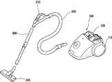
도 3은 본 발명에 의한 진공청소기의 구성을 나타낸 사시도.Figure 3 is a perspective view showing the configuration of a vacuum cleaner according to the present invention.
도 4는 본 발명에 의한 진공청소기 본체의 구성을 나타낸 분해사시도.Figure 4 is an exploded perspective view showing the configuration of the vacuum cleaner main body according to the present invention.
도 5는 본 발명에 의한 진공청소기 본체의 단면을 나타낸 종단면도.5 is a longitudinal sectional view showing a cross section of the vacuum cleaner body according to the present invention;
* 도면의 주요부분에 대한 부호의 설명 *Explanation of symbols on the main parts of the drawings
100 ..... 본체 110 ..... 바퀴100 .....
120 ..... 본체손잡이130 ..... 모터챔버120 ..... Main Unit Handle 130 ..... Motor Chamber
132 ..... 유입구134 ..... 배기부132 ..... Inlet 134 ..... Exhaust
140 ..... 하부케이스142 ..... 분리벽140 .....
150 ..... 중간부152 ..... 집진부150 ..... Middle 152 ..... Dust Collector
154 ..... 배기부관통홀156 ..... 구획판154 ..... exhaust through
160 ..... 먼지봉투고정부170 ..... 집진실커버160 ..... Dust Bag Envelope 170 ..... Dust Collector Cover
172 ..... 힌지174 ..... 연결홀172 ..... Hinge 174 ..... Connecting Hole
F ..... 먼지봉투 M ..... 모터 F ..... Dust Bag M ..... Motor
본 발명은 진공청소기에 관한 것으로, 보다 상세하게는 먼지봉투가 장착되는 집진부와, 모터챔버에 구비된 배기부가 본체 외부로 드러나도록 하는 배기부관통홀을 포함하여 구성되는 중간부를 더 구비함으로써, 외관이 미려해지는 진공청소기의 본체에 관한 것이다.The present invention relates to a vacuum cleaner, and more particularly, by further comprising a dust collecting part to which the dust bag is mounted, and an intermediate part including an exhaust part through-hole to expose the exhaust part provided in the motor chamber to the outside of the main body. It relates to the main body of this beautiful vacuum cleaner.
일반적으로 진공청소기는 회전하는 모터의 강력한 흡입력으로, 오염된 바닥 또는 틈새 등의 먼지나 이물을 흡입함으로써, 먼지나 이물을 본체 내부에 설치된 먼지봉투에 포집할 수 있도록 하는 전기제품이다.In general, a vacuum cleaner is an electric product that allows dust or foreign substances to be collected in a dust bag installed inside the main body by sucking dust or foreign substances such as contaminated floors or crevices with a strong suction force of a rotating motor.
도 1에는 일반적인 진공청소기의 구성을 나타낸 사시도가 도시되어 있다. 도면에 도시된 바와 같이, 진공청소기는 흡입력을 발생하는 본체(2)와, 상기 본체(2) 내부와 연통하도록 연결되고 플렉시블한 재질로 만들어지는 연결호스(4), 상기 연결호스(4)와 길이 조절이 가능하도록 연결되는 연장관(6), 그리고 상기 연장관(6)의 단부에 결합되어 바닥면의 이물을 흡입하는 흡입노즐(8)을 포함하여 구성된다.1 is a perspective view showing the configuration of a general vacuum cleaner. As shown in the drawing, the vacuum cleaner includes a
그리고 상기 본체(2)의 하측에는 바닥면에 접촉하면서 회동 가능하도록 한 쌍의 바퀴(2a)가 설치되어 있어서, 청소기 본체(2)를 원하는 방향으로 이끌 수 있도록 구성된다.And the lower side of the
진공청소기의 사용 중에 다른 장소로 청소기를 이동시키는 경우 연결호스(4)에 형성된 호스손잡이(4a)를 잡고 원하는 방향으로 이동한다. 그러나 이동할 장소가 평면 바닥이 아닌 계단이나 문턱이 있는 경우에는 본체(2)의 상부에서 내부로 오목하게 함몰된 본체파지부(2b)를 파지한 후 청소기를 들어 이동시킨다.When the cleaner is moved to another place while the vacuum cleaner is used, the
도 2에는 도 1의 진공청소기 본체의 단면을 나타낸 종단면도가 도시되어 있다. 도 2에 도시된 바와 같이, 상기 본체(2)는 하부의 바디베이스(10)와 상기 바디베이스(10)의 상부에서 바디베이스(10)의 내부를 차폐하는 바디커버(20)로 전체적인 외관을 형성한다. 그리고 바디커버(20)의 전면에는 유입구(14)가 형성되어 상기 연결호스(4)가 선택적으로 착탈 가능하도록 설치된다.2 is a longitudinal sectional view showing a cross section of the vacuum cleaner body of FIG. 1. As shown in FIG. 2, the
상기 본체(2) 내부의 대략 중앙에는 내부 공간을 좌·우로 구획하는 분리벽(16)이 구비된다. 상기 분리벽(16)의 좌측에는 흡입된 이물이 집진되는 집진부(18)가 형성되고, 상기 분리벽(16)의 우측에는 모터(M)가 설치 고정되는 모터수납실(19)이 형성된다. 그리고, 상기 모터수납실(19)의 후방에는 모터(M)를 통과한 공기를 배기시키기 위한 배기부(19a)가 형성된다.In the center of the inside of the
상기 집진부(18)의 내부에는 상기 유입구(14)를 경유하여 유입된 먼지나 이물을 포집하기 위한 먼지봉투(18a)가 선택적으로 착탈 가능하게 구비된다. 그리고, 상기 먼지봉투(18a)의 표면에는 미세한 통기공(미도시)이 형성되어, 이물을 포함한 공기 중에서 공기만 선택적으로 통과시킴으로써 먼지봉투(18a) 내부에 이물을 포집하게 된다.Inside the
상기 모터수납실(19)의 내부에는 모터챔버(30)가 구비된다. 상기 모터챔버(30)는 모터(M)를 내부에 수용하며 상기 모터(M)에 의해서 발생되는 소음 및 진동을 감소시키는 역할을 수행한다. 그리고, 상기 모터챔버(30)는 모터(M)의 좌·우측을 차폐하는 전방케이스(30a)와 후방케이스(30b)로 구성되어, 볼트에 의하여 결합 된다.The
그리고 상기 후방케이스(30b)의 후면에는 상기 모터(M)를 통과한 공기가 배기부(19a)로 배출될 수 있도록 다수개의 배기부(32)가 형성된다.In addition, a plurality of
상기 배기부(19a)의 일측면에는 상기 모터(M)의 후방 중앙부에 삽입됨으로써 상기 모터(M)가 본체(2) 내부에서 유동하지 않도록 구속하는 모터지지부(34)가 구비된다. 상기 모터지지부(34)는 상기 모터(M)의 진동을 감소시킬 수 있도록 소정의 탄성을 포함하는 고무재질로 성형됨이 바람직하다.One side of the
그러나, 상기와 같이 구성되는 진공청소기에서는 본체(2)의 외관이 바디커버(20)와 바디베이스로(10)만 구성되어 있어서 색상이 단순하고, 미려하지 못한 문제점이 있다.However, in the vacuum cleaner configured as described above, since the appearance of the
본 발명의 목적은 상기와 같은 문제점을 해결하기 위한 것으로, 본체의 중앙에 집진부와 배기부관통홀을 포함하는 중간부를 더 구비함으로써 본체의 외관이 미려해지도록 하는 것에 있다.SUMMARY OF THE INVENTION An object of the present invention is to solve the above problems, and to provide a beautiful appearance of the main body by further providing an intermediate part including a dust collecting part and an exhaust part through-hole in the center of the main body.
상기와 같은 목적을 달성하기 위한 본 발명에 의한 진공청소기의 본체는, 흡입력을 발생하는 모터를 내부에 수용하는 모터챔버와; 상기 모터챔버가 내부에 수용되고, 하부외관을 형성하는 하부케이스와; 상기 하부케이스의 전방을 차폐하고, 후방이 개구됨으로써 상기 모터챔버의 상면이 노출되도록 하는 중간부와; 상기 중간부의 상부에 구비되어 먼지를 필터링하는 먼지봉투가 삽입 고정되는 먼지봉투고 정부와; 상기 먼지봉투고정부의 상부에 회동 가능하도록 구비되어 상기 중간부의 내부 공간을 선택적으로 차폐하는 집진부커버를 포함하여 구성됨을 특징으로 한다.The main body of the vacuum cleaner according to the present invention for achieving the above object includes a motor chamber for accommodating a motor generating a suction force therein; A lower case accommodating the motor chamber and forming a lower appearance; An intermediate portion for shielding the front of the lower case and opening the rear to expose the upper surface of the motor chamber; A dust bag convection unit provided at an upper portion of the intermediate part and having a dust bag for fixing dust inserted therein; The dust bag is provided to be rotatable on top of the fixing portion is characterized in that it comprises a dust collector cover for selectively shielding the inner space of the intermediate portion.
상기 모터챔버의 상부에는 모터챔버 내부로 흡입된 공기가 청소기 상부로 배기되도록 안내하는 배기부가 구비됨을 특징으로 한다.The upper part of the motor chamber is characterized in that the exhaust portion for guiding the air sucked into the motor chamber to be exhausted to the upper portion of the cleaner.
상기 배기부는 상기 모터챔버와 일체로 형성됨을 특징으로 한다.상기 중간부는, 이물을 필터링하는 먼지봉투가 수용되는 집진부와, 상기 집진부의 후방에서 상기 배기부의 외측 테두리와 대응되는 형상으로 천공 성형되어 상기 배기부를 수용함으로써, 상기 배기부가 외부로 드러나도록 하는 배기부관통홀을 포함하여 구성됨을 특징으로 한다.The exhaust part may be formed integrally with the motor chamber. The intermediate part includes a dust collecting part for accommodating a dust bag for filtering a foreign material, and an exhaust part which is perforated in a shape corresponding to an outer edge of the exhaust part at the rear of the dust collecting part to accommodate the exhaust part so that the exhaust part is exposed to the outside. It is characterized by including a through-hole.
이와 같은 구성에 의하면, 본체의 중앙에 집진부과 배기부관통홀을 포함하는 중간부를 더 구비함으로써 본체의 외관이 미려해지는 이점이 있다.According to such a structure, the external part of a main body is provided in the center of a main body including a dust collecting part and an exhaust part through-hole, and the external appearance of a main body has the advantage of being beautiful.
도 3에는 본 발명에 의한 진공청소기의 구성을 나타낸 사시도가 도시되어 있다. 도시된 바와 같이 진공청소기는 흡입력을 발생하는 본체(100)와, 상기 본체(100) 내부와 연통하도록 연결되고 플렉시블한 재질로 만들어지는 연결호스(200), 상기 연결호스(200)와 길이 조절이 가능하도록 연결되는 연장관(300), 그리고 상기 연장관(300)의 단부에 결합되어 바닥면의 이물을 흡입하는 흡입노즐(400)을 포함하여 구성된다.3 is a perspective view showing the configuration of the vacuum cleaner according to the present invention. As shown, the vacuum cleaner is connected to the
그리고 상기 본체(100)의 하측에는 바닥면에 접촉하면서 회동 가능하도록 한 쌍의 바퀴(110)가 설치되어 있어서, 청소기 본체(100)를 원하는 방향으로 이끌 수 있도록 한다.And the lower side of the
진공청소기의 사용 중에 다른 장소로 청소기를 이동시키는 경우 연결호스(200)에 형성된 호스손잡이(210)를 잡고 원하는 방향으로 이동한다. 그러나 이동할 장소가 평면 바닥이 아닌 계단이나 문턱이 있는 경우에는 본체(100)의 상부에서 소정의 높이로 돌출 성형된 본체손잡이(120)를 파지한 후 청소기를 들어 이동시키게 된다.When the cleaner is moved to another place while the vacuum cleaner is in use, the hose handle 210 formed on the
도 4에는 본 발명에 의한 진공청소기 본체의 구성을 나타낸 분해사시도가 도시되어 있고, 도 5에는 본 발명에 의한 진공청소기 본체의 단면을 나타낸 종단면도가 도시되어 있다. 도시된 바와 같이 상기 본체(100)의 하부에는 흡입력을 발생하는 모터를 내부에 수용하는 모터챔버(130)와, 상기 모터챔버(130)를 내부에 수용하고 상기 본체(100)의 하부외관을 형성하는 하부케이스(140)가 구비된다.4 is an exploded perspective view showing the configuration of the vacuum cleaner main body according to the present invention, Figure 5 is a longitudinal sectional view showing a cross section of the vacuum cleaner main body according to the present invention. As shown in the lower portion of the
상기 모터챔버(130)의 상부에는 소정의 통기성을 가지도록 대략 그물망 모양으로 성형되어 상기 모터챔버(130)로 유입된 공기가 상기 본체(100) 외부로 배기되도록 하는 배기부(134)가 구비된다. 상기 배기부(134)는 상기 본체(100)의 상방으로 개구되어 있어서, 상기 모터챔버(130) 내부로 유입된 공기가 상기 본체(100)의 상방으로 배기되도록 한다.The upper portion of the
그리고, 상기 모터챔버(130)의 전방에는 모터챔버(130) 내부로 공기가 유입되도록 하는 유입구(132)가 돌출 형성된다. 상기 유입구(132)는 아래에서 설명할 분리벽(142)과 밀착됨으로써 상기 모터챔버(130) 내부로 유입되는 공기가 누설되지 않도록 하는 역할을 수행한다.In addition, an
상기 하부케이스(140)의 대략 중앙에는 소정의 두께를 가지고 수직 상방으로 돌출 성형된 분리벽(142)이 구비된다. 상기 분리벽(142)은 상기 하부케이스(140)의 내부공간을 좌·우로 구획함으로써 상기 분리벽(142)을 기준으로 우측(도 4에서)에는 모터챔버(130)가 장착 가능하도록 한다.The center of the
상기 하부케이스(140)의 상부에는 상기 모터챔버(130)의 전방을 차폐하고 배기부(134)가 삽입되는 중간부(150)가 구비된다. 상기 중간부(150)의 전방에는 먼지를 필터링하는 먼지봉투(F)가 보관 가능하도록 소정의 깊이를 가지고 하방으로 함몰 성형된 집진부(152)가 구비된다. 그리고, 상기 집진부(152)의 저면은 상기 하부케이스(140)의 전면하부와 대응되는 형상을 가진다.An upper portion of the
상기 집진부(152)의 후방에는 상기 배기부(134)와 대응되는 크기로 천공 성형된 배기부관통홀(154)이 구비된다. 상기 배구부관통홀(154)은 상기 배기부(134)가 삽입되는 곳으로, 삽입된 후에는 상기 배기부(134)가 본체(100) 외부로 노출되도록 한다.At the rear of the
그리고, 상기 중간부(150)의 대략 중앙에는 상기 집진부(152)의 일면을 구성하는 구획판(156)이 형성된다. 상기 구획판(156)은 다수개의 통기공을 포함하는 판모양으로 구비되어 상기 집진부(152)의 먼지봉투(F)에 의해서 정화된 공기가 상기 통기공을 통해서 상기 모터챔버(130)로 유입되도록 한다.In addition, a
상기 중간부(150)와 하부케이스(140)를 결합하게 되면 상기 집진부(152)는 상기 하부케이스(140)의 전방을 덮어서 차폐함과 동시에 집진부(152)를 형성하게 되며, 상기 배기부관통홀(154)은 상기 배기부(134)가 삽입됨으로써 상기 배기부(134)가 상기 본체(100) 외부로 노출되도록 한다.When the
상기 중간부(150)의 상부에는 먼지봉투고정부(160)가 구비된다. 상기 먼지봉투고정부(160)는 상기 집진부(150)의 개구부와 대응되는 형상으로 성형되고, 일측면에 먼지를 필터링하는 먼지봉투(F)가 체결된 상태로 상기 집진부(152)의 상면을 차폐함으로써 상기 집진부(152) 외부로 먼지가 유출되지 않도록 한다.The dust
상기 먼저봉투고정부(160)의 상측에는 상기 집진부커버(170)가 구비된다. 상기 집진부커버(170)는 상기 집진부(152)의 상면을 선택적으로 개방 가능하도록 함으로써 상기 먼지봉투(F)를 교체시에 개방하여 용이하게 개방 가능하도록 하는 역할을 수행한다.The dust collecting
그리고, 상기 집진부커버(170)의 상부 양단에는 상기 집진부커버(170)의 회동중심이 되는 힌지(172)가 돌출 성형된다. 상기 힌지(172)는 본체손잡이(120)의 양단부에 삽입 고정됨으로써 상기 집진부커버(170)가 상기 힌지(172)를 중심으로 회동 가능하도록 한다.In addition, hinges 172, which are pivot centers of the dust collecting
또한, 상기 집진부커버(170)의 상면에는 상기 연장관(300)의 단부와 대응되는 형상으로 천공 성형된 연결홀(174)이 구비된다. 상기 연결홀(174)은 연장관(300)과 연결됨으로써, 상기 흡입노즐(400)로부터 흡입된 이물을 포함하는 공기가 상기 연장관(300) 및 연결호스(200)를 거쳐서 상기 집진부(152)의 먼지봉투(F)로 유입되도록 한다.In addition, the upper surface of the dust collecting
이하에서는 상기와 같이 구성되는 진공청소기의 본체가 동작시에 공기의 유동에 대하여 도 3 및 도 5 를 참조하여 살펴본다. 도 5에는 본 발명에 의한 진공청소기 본체의 단면을 나타낸 종단면도가 도시되어 있다.Hereinafter, the flow of air when the main body of the vacuum cleaner configured as described above will be described with reference to FIGS. 3 and 5. 5 is a longitudinal sectional view showing a cross section of the vacuum cleaner main body according to the present invention.
먼저 본체(100)에 전원을 인가하면, 본체(100) 내부에 내장된 모터(M)에 의해서 흡입력이 발생하게 된다. 모터(M)에 의해서 발생된 흡입력은 흡입노즐(400)에 전달되어 바닥면의 이물과 공기를 흡입하게 되고, 상기 흡입노즐(400)로 유입된 이물을 포함하는 공기는 연장관(300), 연결호스(200) 그리고 연결홀(174)을 거쳐 먼지봉투(F) 내부로 유입된다.First, when power is applied to the
상기 먼지봉투(F) 내부로 유입된 이물은 먼지봉투(F)에 의해서 정화되고, 정화된 공기는 먼지봉투(F)의 외부 즉, 집진부(152)와 구획판(156)을 지나서 상기 본체(100) 후방에 구비된 모터챔버(130)로 유입된다. 그리고, 상기 모터챔버(130)로 유입된 공기는 모터(M) 내부를 통과하여 상기 모터챔버(130) 상부에 천공 성형된 배기부(134)를 통해서 본체(100) 외부로 토출됨으로써 청소는 수행된다.The foreign material introduced into the dust bag (F) is purified by the dust bag (F), the purified air is outside the dust bag (F), that is, the
그리고, 장기간 청소수행으로 상기 먼지봉투(F) 내부에 많은 이물이 집진되면, 흡입력이 저하되므로 상기 먼지봉투(F)를 교체해야 한다. 상기 먼지봉투(F)를 교체시에는 먼저 상기 집진실커버(170)를 힌지(172)를 중심으로 상방으로 회동시켜 상기 집진부(152)를 개방한 후에 상기 먼지봉투고정부(160)를 상기 본체(100)로부터 인출함으로써 먼지봉투고정부(160)의 저면에 고정 장착된 먼지봉투(F)의 교체가 가능하게 된다.In addition, when a lot of foreign matter is collected in the dust bag (F) by the long-term cleaning, the suction force is lowered, so the dust bag (F) should be replaced. When the dust bag F is replaced, the
이러한 본 발명의 범위는 상기에서 예시한 실시예에 한정되지 않고, 상기와 같은 기술범위 안에서 당업계의 통상의 기술자에게 있어서는 본 발명을 기초로 하는 다른 많은 변형이 가능할 것이다.The scope of the present invention is not limited to the above-exemplified embodiments, and many other modifications based on the present invention will be possible to those skilled in the art within the above technical scope.
이상에서 설명한 바와 같이 본 발명에 따르면, 이물을 필터링하는 먼지봉투가 장착되는 집진부과, 상기 모터챔버의 배기부가 외부로 드러나도록 하는 배기부관통홀을 포함하여 구성되는 중간부를 더 구비함으로써 외관이 미려해지는 이점이 있다. As described above, according to the present invention, the appearance is beautiful by further comprising a dust collecting part equipped with a dust bag for filtering foreign matter, and an intermediate part including an exhaust part through-hole for exposing the exhaust part of the motor chamber to the outside. There is an advantage to getting lost.
또한, 모터챔버의 상측에는 모터챔버 내부로 흡입된 공기를 청소기 상부로 배출하는 배기부가 구비됨으로써, 측면 및 후방배기부조에서 발생되는 청소기 주변의 물건의 날림이나, 먼지의 비산이 방지되는 이점이 있다.In addition, the upper side of the motor chamber is provided with an exhaust portion for discharging the air sucked into the motor chamber to the upper portion of the motor chamber, there is an advantage to prevent the flying of objects around the cleaner generated from the side and rear exhaust relief, and the scattering of dust. .
Claims (4)
Translated fromKoreanPriority Applications (4)
| Application Number | Priority Date | Filing Date | Title |
|---|---|---|---|
| KR1020040087095AKR20060037980A (en) | 2004-10-29 | 2004-10-29 | Main body of vacuum cleaner |
| EP05252500AEP1652457B1 (en) | 2004-10-29 | 2005-04-21 | Main body structure of vacuum cleaner |
| DE602005021588TDE602005021588D1 (en) | 2004-10-29 | 2005-04-21 | Main housing arrangement for vacuum cleaners |
| RU2005115914/12ARU2380025C2 (en) | 2004-10-29 | 2005-05-25 | Construction of vacuum-cleaner main case |
Applications Claiming Priority (1)
| Application Number | Priority Date | Filing Date | Title |
|---|---|---|---|
| KR1020040087095AKR20060037980A (en) | 2004-10-29 | 2004-10-29 | Main body of vacuum cleaner |
Publications (1)
| Publication Number | Publication Date |
|---|---|
| KR20060037980Atrue KR20060037980A (en) | 2006-05-03 |
Family
ID=35717547
Family Applications (1)
| Application Number | Title | Priority Date | Filing Date |
|---|---|---|---|
| KR1020040087095ACeasedKR20060037980A (en) | 2004-10-29 | 2004-10-29 | Main body of vacuum cleaner |
Country Status (4)
| Country | Link |
|---|---|
| EP (1) | EP1652457B1 (en) |
| KR (1) | KR20060037980A (en) |
| DE (1) | DE602005021588D1 (en) |
| RU (1) | RU2380025C2 (en) |
Families Citing this family (5)
| Publication number | Priority date | Publication date | Assignee | Title |
|---|---|---|---|---|
| DE102008041228A1 (en)* | 2008-08-13 | 2010-02-18 | BSH Bosch und Siemens Hausgeräte GmbH | vacuum cleaner |
| JP5484812B2 (en)* | 2009-07-21 | 2014-05-07 | 三洋電機株式会社 | Electric vacuum cleaner |
| CN102525343A (en)* | 2010-12-16 | 2012-07-04 | 莱克电气股份有限公司 | Dust bag type dust collector |
| CN105212829A (en)* | 2015-09-07 | 2016-01-06 | 太仓文广汇清洁设备有限公司 | A kind of portable dust collector |
| EP3684237B1 (en) | 2017-09-22 | 2023-07-19 | SharkNinja Operating LLC | Hand-held surface cleaning device |
Family Cites Families (6)
| Publication number | Priority date | Publication date | Assignee | Title |
|---|---|---|---|---|
| US4527302A (en)* | 1983-11-21 | 1985-07-09 | The Hoover Company | Canister cleaner |
| FR2641460B1 (en)* | 1989-01-12 | 1993-04-09 | Moulinex Sa | METHOD FOR ASSEMBLING ELEMENTS OF A VACUUM HOUSING AND HOUSING ASSEMBLED ACCORDING TO SUCH A METHOD |
| DE19616156C1 (en)* | 1996-04-23 | 1997-10-02 | Fakir Werk Gmbh & Co | Vacuum cleaner with housing comprising lower and upper parts |
| JP2001238827A (en)* | 2000-02-29 | 2001-09-04 | Toshiba Tec Corp | Electric vacuum cleaner |
| TR200300942T1 (en)* | 2000-12-22 | 2007-01-22 | Arçeli̇k Anoni̇m Şi̇rketi̇ | Vacuum cleaner |
| KR100432730B1 (en)* | 2001-10-15 | 2004-05-24 | 엘지전자 주식회사 | Device for protecting moter in vacuum cleaner |
- 2004
- 2004-10-29KRKR1020040087095Apatent/KR20060037980A/ennot_activeCeased
- 2005
- 2005-04-21DEDE602005021588Tpatent/DE602005021588D1/ennot_activeExpired - Lifetime
- 2005-04-21EPEP05252500Apatent/EP1652457B1/ennot_activeCeased
- 2005-05-25RURU2005115914/12Apatent/RU2380025C2/ennot_activeIP Right Cessation
Also Published As
| Publication number | Publication date |
|---|---|
| EP1652457B1 (en) | 2010-06-02 |
| EP1652457A1 (en) | 2006-05-03 |
| RU2380025C2 (en) | 2010-01-27 |
| DE602005021588D1 (en) | 2010-07-15 |
| RU2005115914A (en) | 2006-11-27 |
Similar Documents
| Publication | Publication Date | Title |
|---|---|---|
| US11653800B2 (en) | Handheld vacuum cleaner | |
| EP1674009B1 (en) | Vacuum cleaner | |
| EP1674019B1 (en) | Dust collection unit and vacuum cleaner with the same | |
| EP1674017B1 (en) | Dust collection unit and vacuum cleaner with the same | |
| US7404231B2 (en) | Dust container of upright type vacuum cleaner and supporting structure for cover thereof | |
| US7491255B2 (en) | Dust collection unit for vacuum cleaner | |
| US9125534B2 (en) | Vacuum cleaner | |
| KR20090095333A (en) | Vacuum cleaner in which dust bag or cyclone dust collecting apparatus is selectively mounted | |
| EP1674023A1 (en) | Multi-cyclone dust collecting unit and vacuum cleaner comprising same | |
| KR20060125952A (en) | Dust collection unit | |
| KR100809738B1 (en) | Vacuum cleaner | |
| US20190150687A1 (en) | Robot cleaner | |
| KR20060037980A (en) | Main body of vacuum cleaner | |
| US7442219B2 (en) | Dust collection unit for vacuum cleaner | |
| KR100730944B1 (en) | Exhaust flow path structure of vacuum cleaner | |
| KR102081941B1 (en) | Cleaning Appliance | |
| KR101480304B1 (en) | Cyclone dust collectors and vacuum cleaners | |
| KR20090035551A (en) | Vacuum cleaner | |
| KR20060018716A (en) | Motor chamber of vacuum cleaner | |
| KR101282536B1 (en) | Dust collecting apparatus and electric cleaner | |
| KR20050066908A (en) | Dirt and dust casing for up right type cacuum cleaner | |
| KR101066694B1 (en) | Dust collector of vacuum cleaner | |
| KR20160096324A (en) | Vacuum suction device for dust removal device for shoes | |
| KR200394919Y1 (en) | Dust collecting unit | |
| KR100640831B1 (en) | Vacuum cleaner |
Legal Events
| Date | Code | Title | Description |
|---|---|---|---|
| PA0109 | Patent application | Patent event code:PA01091R01D Comment text:Patent Application Patent event date:20041029 | |
| PG1501 | Laying open of application | ||
| A201 | Request for examination | ||
| PA0201 | Request for examination | Patent event code:PA02012R01D Patent event date:20090715 Comment text:Request for Examination of Application Patent event code:PA02011R01I Patent event date:20041029 Comment text:Patent Application | |
| E902 | Notification of reason for refusal | ||
| PE0902 | Notice of grounds for rejection | Comment text:Notification of reason for refusal Patent event date:20110304 Patent event code:PE09021S01D | |
| E601 | Decision to refuse application | ||
| PE0601 | Decision on rejection of patent | Patent event date:20111128 Comment text:Decision to Refuse Application Patent event code:PE06012S01D Patent event date:20110304 Comment text:Notification of reason for refusal Patent event code:PE06011S01I |