KR20060021922A - Obstacle detection technology and device using two cameras - Google Patents
Obstacle detection technology and device using two camerasDownload PDFInfo
- Publication number
- KR20060021922A KR20060021922AKR1020060008547AKR20060008547AKR20060021922AKR 20060021922 AKR20060021922 AKR 20060021922AKR 1020060008547 AKR1020060008547 AKR 1020060008547AKR 20060008547 AKR20060008547 AKR 20060008547AKR 20060021922 AKR20060021922 AKR 20060021922A
- Authority
- KR
- South Korea
- Prior art keywords
- camera
- image
- obstacle
- road
- coordinates
- Prior art date
- Legal status (The legal status is an assumption and is not a legal conclusion. Google has not performed a legal analysis and makes no representation as to the accuracy of the status listed.)
- Ceased
Links
- 238000001514detection methodMethods0.000titleclaimsabstractdescription23
- 238000000034methodMethods0.000claimsdescription35
- 239000000284extractSubstances0.000claimsdescription5
- 238000004364calculation methodMethods0.000abstractdescription10
- 238000003384imaging methodMethods0.000description6
- 238000010586diagramMethods0.000description3
- 238000010998test methodMethods0.000description1
Images

Classifications
- B—PERFORMING OPERATIONS; TRANSPORTING
- B60—VEHICLES IN GENERAL
- B60R—VEHICLES, VEHICLE FITTINGS, OR VEHICLE PARTS, NOT OTHERWISE PROVIDED FOR
- B60R1/00—Optical viewing arrangements; Real-time viewing arrangements for drivers or passengers using optical image capturing systems, e.g. cameras or video systems specially adapted for use in or on vehicles
- B60R1/02—Rear-view mirror arrangements
- B60R1/08—Rear-view mirror arrangements involving special optical features, e.g. avoiding blind spots, e.g. convex mirrors; Side-by-side associations of rear-view and other mirrors
- B60R1/081—Rear-view mirror arrangements involving special optical features, e.g. avoiding blind spots, e.g. convex mirrors; Side-by-side associations of rear-view and other mirrors avoiding blind spots, e.g. by using a side-by-side association of mirrors
- B—PERFORMING OPERATIONS; TRANSPORTING
- B60—VEHICLES IN GENERAL
- B60R—VEHICLES, VEHICLE FITTINGS, OR VEHICLE PARTS, NOT OTHERWISE PROVIDED FOR
- B60R21/00—Arrangements or fittings on vehicles for protecting or preventing injuries to occupants or pedestrians in case of accidents or other traffic risks
- B60R21/01—Electrical circuits for triggering passive safety arrangements, e.g. airbags, safety belt tighteners, in case of vehicle accidents or impending vehicle accidents
- B60R21/013—Electrical circuits for triggering passive safety arrangements, e.g. airbags, safety belt tighteners, in case of vehicle accidents or impending vehicle accidents including means for detecting collisions, impending collisions or roll-over
- G—PHYSICS
- G01—MEASURING; TESTING
- G01C—MEASURING DISTANCES, LEVELS OR BEARINGS; SURVEYING; NAVIGATION; GYROSCOPIC INSTRUMENTS; PHOTOGRAMMETRY OR VIDEOGRAMMETRY
- G01C11/00—Photogrammetry or videogrammetry, e.g. stereogrammetry; Photographic surveying
- G01C11/36—Videogrammetry, i.e. electronic processing of video signals from a single source or from different sources to give parallax or range information
- B—PERFORMING OPERATIONS; TRANSPORTING
- B60—VEHICLES IN GENERAL
- B60R—VEHICLES, VEHICLE FITTINGS, OR VEHICLE PARTS, NOT OTHERWISE PROVIDED FOR
- B60R2300/00—Details of viewing arrangements using cameras and displays, specially adapted for use in a vehicle
- B60R2300/10—Details of viewing arrangements using cameras and displays, specially adapted for use in a vehicle characterised by the type of camera system used
- B60R2300/105—Details of viewing arrangements using cameras and displays, specially adapted for use in a vehicle characterised by the type of camera system used using multiple cameras
- B—PERFORMING OPERATIONS; TRANSPORTING
- B60—VEHICLES IN GENERAL
- B60R—VEHICLES, VEHICLE FITTINGS, OR VEHICLE PARTS, NOT OTHERWISE PROVIDED FOR
- B60R2300/00—Details of viewing arrangements using cameras and displays, specially adapted for use in a vehicle
- B60R2300/30—Details of viewing arrangements using cameras and displays, specially adapted for use in a vehicle characterised by the type of image processing
- B60R2300/304—Details of viewing arrangements using cameras and displays, specially adapted for use in a vehicle characterised by the type of image processing using merged images, e.g. merging camera image with stored images
- B—PERFORMING OPERATIONS; TRANSPORTING
- B60—VEHICLES IN GENERAL
- B60R—VEHICLES, VEHICLE FITTINGS, OR VEHICLE PARTS, NOT OTHERWISE PROVIDED FOR
- B60R2300/00—Details of viewing arrangements using cameras and displays, specially adapted for use in a vehicle
- B60R2300/80—Details of viewing arrangements using cameras and displays, specially adapted for use in a vehicle characterised by the intended use of the viewing arrangement
- B60R2300/802—Details of viewing arrangements using cameras and displays, specially adapted for use in a vehicle characterised by the intended use of the viewing arrangement for monitoring and displaying vehicle exterior blind spot views
Landscapes
- Engineering & Computer Science (AREA)
- Multimedia (AREA)
- Mechanical Engineering (AREA)
- Signal Processing (AREA)
- Physics & Mathematics (AREA)
- General Physics & Mathematics (AREA)
- Radar, Positioning & Navigation (AREA)
- Remote Sensing (AREA)
- Traffic Control Systems (AREA)
Abstract
Translated fromKoreanDescription
Translated fromKorean도 1a 및 1b는 본 발명의 바람직한 실시예에 따른 두 대의 카메라를 이용한 장애물 감지 기술 및 장치를 구현하는 장치의 블록구성도,1A and 1B are block diagrams of an apparatus for implementing an obstacle sensing technique and apparatus using two cameras according to a preferred embodiment of the present invention;
도 2는 본 발명에 따른 두 대의 카메라를 이용한 장애물 감지 기술 및 장치를 설명하기 위한 플로우차트,2 is a flowchart illustrating an obstacle detection technique and apparatus using two cameras according to the present invention;
도 3a와 도 3b와 도 3c와 도 3d는 본 발명에 따른 장애물 감지 기술을 설명하기 위한 도면이다.3A, 3B, 3C, and 3D are diagrams for describing an obstacle sensing technique according to the present invention.
*도면의 주요 부분에 대한 부호의 설명** Description of the symbols for the main parts of the drawings *
10: 촬상부, 12: 영상처리부,10: imaging unit, 12: image processing unit,
14: 장애물감지및거리연산부, 16: 속도제어부,14: obstacle detection and distance calculation unit, 16: speed control unit,
16a: 악셀페달구동모터, 16b: 브레이크페달구동모터,16a: Axel pedal drive motor, 16b: Brake pedal drive motor,
17: 경고발생부, 18: 표시부,17: warning unit, 18: display unit,
60: 휴대폰.60: cell phone.
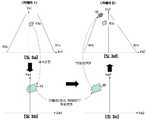
본 발명은 두 개의 카메라를 이용한 장애물 감지 기술 및 그 장치에 관한 것으로, 보다 상세하게는 주행 중인 차량의 전방 도로영상을 두 대의 카메라로 촬영하고 두 대의 카메라 중 첫 번째 카메라에서 추출된 물체가 도로 바닥에 납작하게 놓여있다고 가정하였을 때, 이 물체를 두 번째 카메라가 촬영한다면 영상에 나타나야 될 위치를 계산하고 실제 촬영된 물체의 위치와 비교하여 위치의 차이가 있을 경우에만 이를 장애물로 인식하여 장애물 경보를 발생시키거나 장애물과의 추돌 방지를 위한 속도 조절을 하기 위한 두 대의 카메라를 이용한 장애물 감지 기술과 그 장치에 관한 것이다.The present invention relates to an obstacle sensing technology using two cameras and a device thereof, and more particularly, to photograph an image of a road in front of a driving vehicle with two cameras, and an object extracted from the first of the two cameras is a road floor. Assuming that the second camera is photographing this object, if the second camera captures this object, it calculates the position that should appear on the image and compares it with the position of the actual object, and recognizes it as an obstacle only when there is a difference in position. The present invention relates to an obstacle detection technology and a device using two cameras for speed control to generate or prevent collision with an obstacle.
최근, 사물을 인지할 수 있는 지능형 시스템에 대한 관심이 증가하면서 이를 구현하기 위한 3차원 영상 기술에 대한 관심이 고조되고 있다. 이에 대한 많은 방법론들이 제기되고 있으나 가장 일반적인 방법으로는 사람의 눈이 3차원 공간에서의 사물을 인식하는 원리로 만들어진 스테레오 비전(Stereo vision)이 있다.Recently, as interest in intelligent systems capable of recognizing objects increases, interest in three-dimensional imaging technology for realizing them has increased. Many methodologies have been proposed, but the most common method is stereo vision, which is made on the principle that the human eye recognizes objects in three-dimensional space.
스테레오 비전은 기준선만큼 떨어진 두 대의 카메라의 좌우영상으로부터 물체에 대한 대응점(corresponding point)을 찾아내어야 하며, 그리고 그 대응점에 대한 공간상의 시점차(disparity)를 이용하여 3차원 좌표값을 산출하는 방식이다.Stereo vision needs to find the corresponding point of the object from the left and right images of two cameras separated by the reference line, and calculate the 3D coordinate value by using the spatial disparity of the corresponding point. .
이에비하여, 본 발명은 두 대의 카메라를 이용한다는 점에서는 스테레오 비전과 동일하나 본 발명에서는 영상의 대응점을 찾을 필요가 없고 단지 첫 번째 카메라에 나타난 물체가 노면으로부터 돌출되었는지 아닌지를 두 번째 카메라 영상에 나타난 물체와의 위치 비교만을 통하여 검정하는 방법으로 스테레오 비전에서 필요한 대응점을 구하는 어려움과 각 대응점까지의 거리를 계산할 필요가 없다는 점에서 처리속도와 장애물 판별 기능이 개선되었다.In contrast, the present invention is the same as stereo vision in that it uses two cameras, but in the present invention, it is not necessary to find the corresponding point of the image, but only in the second camera image whether or not the object shown in the first camera protrudes from the road surface. The processing speed and the obstacle discrimination function are improved in that it is difficult to find the necessary correspondence point in the stereo vision and the distance to each correspondence point is not needed by the test method by comparing the position with the object.
본 기술은 상기한 종래 기술의 어려움을 개선하여 이루어진 것으로, 두 대의 카메라가 전방 도로영상을 촬영하여, 두 대 중 한 대 카메라의 영상에 찍힌 물체를 도로면으로부터 돌출되어있지 않은 물체로 가정하고 이 물체를 다른 카메라가 촬영한다면 촬영된 영상에 나타나야 될 위치를 계산하고 실제로 영상에 찍힌 위치를 비교함으로써 장애물의 유무를 판단하고 장애물까지의 거리는 모노 카메라 방식에 의하여 계산하는 두 대의 카메라를 이용한 장애물 감지 기술 및 장치를 제공함에 그 목적이 있다.The present technology is made by improving the above-mentioned difficulty of the prior art, and it is assumed that two cameras photograph an image of the road ahead, and that the object captured by the image of one of the two cameras is an object that does not protrude from the road surface. Obstacle detection technology using two cameras to determine the presence of obstacles and calculate the distance to the obstacles by mono camera method, if the object is taken by another camera, calculate the position that should appear in the captured image and compare the position actually recorded on the image. And to provide a device.
상기한 목적을 달성하기 위해, 본 발명의 바람직한 실시예에 따르면 두 대의 카메라(제 1카메라, 제 2카메라)로 주행 차량의 전방 도로정보영상을 촬영하여 각각의 카메라로 그 차량의 좌우측 차선정보를 추출하고 차선 내 물체의 윤곽선 추출, 그 영상 좌표를 계산하는 제 1과정과; 상기 계산된 영상 좌표를 도로 좌표로 변환시키고 그 도로 좌표 값을 다시 제 2카메라에 대한 도로 좌표 값으로 변환시킨 후 그 도로 좌표 값에 있는 물체가 제 2카메라의 영상 상에 위치되어야 할 영상 좌표 값을 계산하여 제 2카메라의 영상에 표시하는 제 2과정; 상기 변환된 제 2카메라에 대한 영상 좌표 값과 실제 제 2카메라에 찍힌 물체의 영상 좌표 값을 비교하여 장애물의 유무를 판단하는 제 3과정; 상기 물체가 장애물이라고 판단되었을 경우 제 1카메로부터 상기 물체의 최하단까지의 거리를 구하여 속도를 조절하고 경보를 울리는 제 4과정을 포함하는 두 대의 카메라를 이용한 장애물 감지 기술 및 장치가 제공된다.In order to achieve the above object, according to a preferred embodiment of the present invention two road cameras (first camera, the second camera) to take a road information image of the front of the driving vehicle and each of the left and right lane information of the vehicle Extracting, extracting contours of the object in the lane, and calculating image coordinates; After converting the calculated image coordinates to road coordinates and converting the road coordinate values back to road coordinate values for the second camera, an object at the road coordinate values should be positioned on the image of the second camera. Calculating a second value and displaying the image on an image of the second camera; A third step of determining whether an obstacle is present by comparing an image coordinate value of the converted second camera with an image coordinate value of an object actually photographed by the second camera; When it is determined that the object is an obstacle, there is provided an obstacle detecting technology and apparatus using two cameras including a fourth process of adjusting a speed by generating a distance from the first camera to the lowest end of the object and generating an alarm.
바람직하게, 상기 제 1과정에서는 상기 차량에 장착된 두 대의 카메라 중 제 1카메라를 이용하여 영상에 찍힌 물체의 윤곽선을 구하고 그 윤곽선의 영상 좌표값을 구하게 된다.Preferably, in the first process, an outline of an object captured on an image is obtained by using a first camera of two cameras mounted on the vehicle, and image coordinate values of the outline are obtained.
상기 제 2과정에서는 상기 제 1과정에서 얻은 물체의 윤곽선을 이루는 픽셀들의 영상 좌표 값을 도로 좌표 값으로 변환을 시키고 이 도로좌표를 제 2카메라를 기준으로 하는 새로운 도로 좌표로 변환시켜 이 도로 좌표값이 제 2카메라의 영상에 나타나야 될 예상 영상 좌표 값을 계산하여 영상에 표시해주게 된다.In the second process, the image coordinate values of the pixels forming the outline of the object obtained in the first process are converted into road coordinate values, and the road coordinates are converted into new road coordinates based on the second camera. The expected image coordinate values that should appear in the image of the second camera are calculated and displayed on the image.
상기 제 3과정에서는 상기 제 2과정에서 구한 예상 영상 좌표 값과 실제로 두 번째 카메라에 찍힌 물체의 영상 좌표 값의 차이를 계산하여 장애물임을 판단하게 된다.In the third process, it is determined that the obstacle is calculated by calculating a difference between the expected image coordinate value obtained in the second process and the image coordinate value of the object actually photographed by the second camera.
상기 제 4과정에서는 상기 제 3과정에서 장애물임이 판단되었을 경우 제 1카메라에 찍힌 물체의 영상의 최하단점이 노면에 접하였다고 간주하고 그 점까지의 거리를 계산하여 이를 장애물까지의 거리로 판단하여 이를 표시부에 출력하거나 속도제어부(ACC)에 신호를 보내 주행 차량이 장애물을 회피하도록 속도를 제어하게 된다.In the fourth process, if it is determined that the obstacle is the third process, the lowest end point of the image of the object photographed by the first camera is considered to be in contact with the road surface, the distance to the point is calculated, and the distance to the obstacle is determined and displayed. It outputs to or sends a signal to the speed controller ACC to control the speed so that the traveling vehicle avoids obstacles.
본 발명의 다른 예에 따르면, 상기 제 1과정, 제 2과정, 제 3과정, 제 4과정은 카메라가 부착된 휴대폰과 네비게이션 중 어느 하나에 의해서도 구현될 수 있다.According to another example of the present invention, the first process, the second process, the third process, and the fourth process may be implemented by any one of a mobile phone equipped with a camera and a navigation.
본 발명에 대한 첨부도면을 참조하여 상세하게 설명한다.It will be described in detail with reference to the accompanying drawings for the present invention.
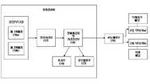
도 1a와 도 1b는 본 발명의 바람직한 실시예에 따른 두 대의 카메라를 이용한 장애물 감지 기술 및 장치를 구현하는 장치의 블록구성도이다.1A and 1B are block diagrams of an apparatus for implementing an obstacle sensing technique and apparatus using two cameras according to a preferred embodiment of the present invention.
도면에서, 10은 차량의 전면 상단에 장착되어 차량의 주행 전방을 촬영하여 도로정보영상을 형성하는 촬상부로서, 그 촬상부(10)는 예컨대 CCD 카메라나 CMOS 카메라 또는 적정한 영상촬영장치로 구성된다.In the drawing, reference numeral 10 denotes an image capturing unit which is mounted on the upper front of the vehicle and photographs the driving front of the vehicle to form a road information image. .
12는 상기 촬상부(10)에서 촬상된 차량전방의 도로정보영상을 수취하여 주지의 영상처리기법을 적용하여 차량주행로의 좌측차선과 우측차선을 추출하고 차량전방에 위치된 물체을 추출해내는 영상처리부로서, 그 영상처리부(12)에 의한 주지의 영상처리기법으로는 예컨대 도로정보영상에서 명암대비에 의해 좌측차선과 우측차선 그리고 도로면에 위치된 물체의 검출이 가능하게 된다.12 is an image processing unit which receives the road information image of the front of the vehicle captured by the imaging unit 10 and extracts the left lane and the right lane of the vehicle driving lane by applying a known image processing technique and extracts the object located in the front of the vehicle. As a known image processing technique by the
14는 상기 영상처리부(12)에서 검출된 차량 전방의 물체에 대한 정보에 기초하여 주지의 공식에 의하여 장애물의 유무를 판단하고 장애물이라 판단되었을 경우 장애물이 존재함을 알리고 카메라로부터 장애물까지의 거리를 구하는 장애물감지 및 거리연산부로서, 그 장애물감지 및 거리연산부에 의한 주지의 공식으로는 예컨대 두 대의 카메라에 찍힌 같은 물체에 대한 좌표값 간의 차를 이용하여 장애물을 검출하고 삼각함수 기법을 이용하여 거리를 측정할 수 있게 된다.14 determines the presence or absence of an obstacle according to a well-known formula based on the information on the object in front of the vehicle detected by the
16은 상기 장애물감지 및 거리연산부(14)에서 인가되는 장애물의 유무와 카메라로부터 장애물까지의 거리에 의하여 브레이크 페달을 구동시키는 모터(16a)와 악셀 페달을 구동시키는 모터(16b)가 제어되도록 하는 속도제어부(ACC)이다.16 is a speed at which the motor 16a for driving the brake pedal and the motor 16b for driving the axel pedal are controlled by the presence or absence of an obstacle applied by the obstacle detection and
여기서, 상기 속도제어부(16)은 상기 거리연산부(14)로부터 전달되는 장애물까지의 거리가 일정 임계치 이상이 될 때까지 전방 장애물까지의 차량의 접근 속도 조절을 실행하게 된다.Here, the
17은 상기 장애물감지 및 거리연산부(14)에서 인가되는 장애물의 유무와 카메라로부터 장애물까지의 거리에 의하여 장애물 감지 경보를 출력하여 차량과 장애물의 충돌을 막기 위하여 운전자에게 경보해주는 경보발생부이다.17 is an alarm generating unit that alerts the driver to prevent a collision between the vehicle and the obstacle by outputting an obstacle detection alarm based on the presence or absence of an obstacle applied by the obstacle detection and
18은 차량 내에 설치되어 두 대의 카메라에서 찍는 도로 전방 영상과 장애물의 유무를 시각적으로 확인가능 하도록 표시해주는 표시부이다.18 is a display unit installed in the vehicle to visually identify the road ahead image taken by the two cameras and the presence of obstacles.
여기서, 상기 영상처리부(12)와 상기 장애물감지 및 거리연산부(14)는 차량의 전자에어를 위해 설치되는 ECU가 적용되거나 별도의 엠베디드콘트롤시스템(Embeded Control System)을 적용해도 된다.Here, the
한편, 본 발명은 상기한 바와 같이 별개의 장치로 구성되어 차량에 탑재되어도 되지만, 도 1b에 예시된 바와 같이 카메라가 부착된 휴대폰에도 적용하거나 도로 안내기능의 네비게이션에 카메라를 연계시켜 적용해도 된다.On the other hand, the present invention is configured as a separate device as described above may be mounted in a vehicle, but may also be applied to a mobile phone with a camera as shown in Figure 1b or may be applied in conjunction with the camera to the navigation of the road guidance function.
즉, 휴대폰 또는 네비게이션(60)에 부착된 카메라가 상기 촬상부(10)의 기능을 수행하도록 하고 휴대폰 또는 네비게이션의 제어수단(CPU 또는 마이컴)이 상기 영상처리부(12) 및 상기 장애물감지 및 거리연산부(14)의 기능을 수행하도록 하며 상기 표시부(18)는 해당하는 휴대폰 또는 네비게이션에 갖추어진 표시수단에 의해 그 기능을 구현하도록 하고 상기 경보발생부(18)는 휴대폰 또는 네비게이션의 음향출력장치에 의해 기능하도록 함으로써 휴대폰에 의해 그 기능이 실행되도록 구성될 수 있다.That is, the camera attached to the mobile phone or the navigation 60 performs the function of the imaging unit 10 and the control means (CPU or microcomputer) of the mobile phone or the navigation is the
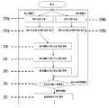
상기한 구성의 본 발명에 따른 장애물 감지 기술 및 그 장치에 대해 도2에 도시된 플로우차트를 참조하여 상세하게 설명한다.The obstacle detection technique and its apparatus according to the present invention having the above-described configuration will be described in detail with reference to the flowchart shown in FIG.
먼저, 도로상의 주행하는 차량의 전면 상단에 설치된 상기 촬상부(10)의 제 1카메라(10a)와 제 2카메라(10b)에서 촬영된 도로정보영상이 상기 영상처리부(12)에 인가되면 그 영상처리부(12)는 단계 20a와 단계 20b에서 상기 주행중인 차량의 전방 도로정보영상으로부터 해당하는 차량의 좌측차선(도 3a에서 40a, 42a 참조)과 우측차선(도 3a에서 40b, 42b 참조)을 추출하고 단계 22a와 22b에서는 상기 주행중인 차량의 전방 도로정보영상으로부터 상기 단계 20a와 20b에서 추출된 좌우측 차선 내에 있는 물체의 윤곽선을 추출하여 화면에 표시해 주고 그 윤곽선의 좌표값을 계산하여 그 값을 상기 장애물감지 및 거리연산부(14)로 인가하게 된다.First, when the road information image photographed by the
단계 24에서 해당하는 차량의 현재 위치에서 전방향을 Yw-축으로 설정함과 더불어 그 Yw-축에 직각이면서 해당하는 차량의 중심을 통과하는 축을 Xw-축으로 설정하여 도로좌표로 정의하는 경우, 상기 장애물감지 및 거리연산부(14)는 상기 영상처리부(12)로부터 인가된 상기 제 1카메라(10a)에 찍힌 좌우측 차선 내에 있는 물체의 윤곽선의 좌표값을 물체가 도로 표면에 평평하게 놓여있다는 가정 하에 도로 좌표 값으로 변환(도 3b에서 45 참조) 된다.In
단계 26에서 상기 장애물감지 및 거리연산부(14)는 단계 24에서 좌표 변환된 제 1카메라(10a)의 도로 좌표를 제 2카메라(10b)의 도로 좌표계로 변환(도 3c에서 46 참조)을 시킨다.In
단계 28에서 상기 장애물감지 및 거리연산부(14)는 단계 26에서 좌표 변환된 제 2카메라(10b) 기준 도로 좌표값을 영상 좌표 값(도 3d의 48 참조)으로 역변환을 시켜 표시부(18)에 표시되도록 한다.In
단계 30에서 상기 장애물감지 및 거리연산부(14)는 단계 28에서 역변환된 제 2카메라(10b)의 예상 영상 좌표(48)를 단계 22b에서 추출된 물체의 실제 영상 좌표값(43b)과 비교하여 두 좌표값의 차이가 정해진 임계치 값 이상이면 이를 장애물로 판단한다.In
단계 32에서 상기 장애물감지 및 거리연산부(14)는 단계 30에서 주행 차량의 전방에 장애물이 있다고 판단되었을 경우, 제 1카메라(10a)와 단계 22a에서 추출된 물체의 최하단점까지의 거리는 주지의 모노 카메라 방법을 이용하여 계산하고 상기 속도제어부(16)에 거리정보를 인가하여 계산된 브레이크 페달 구동 모터(16a)나 혹은 악셀 페달 구동 모터(16b)를 가동시켜 속도를 조절할 수 있도록 하며, 경보발생부에 장애물이 있음을 알려 경보가 울릴 수 있도록 한다.If it is determined in
상기한 바와 같이, 본 발명에 따른 두 대의 카메라를 이용한 장애물 감지 기술 및 장치에 의하면, 기존의 스테레오 비전과 같이 대상 영역에 대한 대응점을 탐색할 필요가 없이 한 대의 카메라에서 나타난 물체가 노면으로부터 돌출되었는지 아닌지를 두 번째 카메라 영상에 나타난 물체와의 위치 비교만을 통하여 검정하는 방법으로 장애물로 판별되었을 경우에는 장애물의 최하단점까지의 거리를 모노 카메라 방식으로 계산함으로써 복잡한 계산을 줄여 처리속도를 높이고 장애물 판별의 정확성을 높일 수 있다.As described above, according to the obstacle detection technology and apparatus using two cameras according to the present invention, as shown in the conventional stereo vision, there is no need to search for a corresponding point to a target area, and whether an object represented by one camera protrudes from the road surface. If it is identified as an obstacle only by comparing the position with the object shown in the second camera image, the distance to the lowest end of the obstacle is calculated by the mono camera method to reduce the complicated calculations to increase the processing speed and You can increase the accuracy.
유리하게, 본 발명에 따르면, 상기 촬상부(10)와 상기 영상처리부(12), 상기 제어연산부(14) 및 상기 표시부(18)는 카메라가 부착된 휴대폰 또는 네비게이션에 의해 구현되도록 할 수도 있다.Advantageously, according to the present invention, the imaging unit 10, the
Claims (4)
Translated fromKoreanPriority Applications (1)
| Application Number | Priority Date | Filing Date | Title |
|---|---|---|---|
| KR1020060008547AKR20060021922A (en) | 2006-01-26 | 2006-01-26 | Obstacle detection technology and device using two cameras |
Applications Claiming Priority (1)
| Application Number | Priority Date | Filing Date | Title |
|---|---|---|---|
| KR1020060008547AKR20060021922A (en) | 2006-01-26 | 2006-01-26 | Obstacle detection technology and device using two cameras |
Publications (1)
| Publication Number | Publication Date |
|---|---|
| KR20060021922Atrue KR20060021922A (en) | 2006-03-08 |
Family
ID=37128582
Family Applications (1)
| Application Number | Title | Priority Date | Filing Date |
|---|---|---|---|
| KR1020060008547ACeasedKR20060021922A (en) | 2006-01-26 | 2006-01-26 | Obstacle detection technology and device using two cameras |
Country Status (1)
| Country | Link |
|---|---|
| KR (1) | KR20060021922A (en) |
Cited By (11)
| Publication number | Priority date | Publication date | Assignee | Title |
|---|---|---|---|---|
| KR100757596B1 (en)* | 2006-05-18 | 2007-09-10 | 현대자동차주식회사 | An apparatus and method for detecting front side distance using image processing technology |
| KR100906991B1 (en)* | 2007-11-07 | 2009-07-10 | 전자부품연구원 | Invisible Obstacle Detection Method of Robot |
| KR100929569B1 (en)* | 2008-08-28 | 2009-12-03 | 전자부품연구원 | Obstacle Information System |
| KR101371875B1 (en)* | 2011-11-28 | 2014-03-07 | 현대자동차주식회사 | A vehicle detection and distance measurement system and method between the vehicles using stereo vision |
| CN103770703A (en)* | 2012-10-19 | 2014-05-07 | 纳诺科技股份有限公司 | Driving image identification device and method thereof |
| KR20160049805A (en)* | 2014-10-28 | 2016-05-10 | 현대모비스 주식회사 | Apparatus and method for controlling outputting information about blind spots of vehicle using mobile device |
| WO2020046280A1 (en)* | 2018-08-28 | 2020-03-05 | Hewlett-Packard Development Company, L.P. | Obstacle detection |
| CN112577475A (en)* | 2021-01-14 | 2021-03-30 | 天津希格玛微电子技术有限公司 | Video ranging method capable of effectively reducing power consumption |
| CN112989883A (en)* | 2019-12-16 | 2021-06-18 | 中国科学院沈阳计算技术研究所有限公司 | Method for identifying obstacle in front of train |
| CN113727071A (en)* | 2021-08-30 | 2021-11-30 | 合众新能源汽车有限公司 | Road condition display method and system |
| WO2023013811A1 (en)* | 2021-08-04 | 2023-02-09 | 주식회사 넥스트칩 | Object detection method and electronic device for performing same method |
- 2006
- 2006-01-26KRKR1020060008547Apatent/KR20060021922A/ennot_activeCeased
Cited By (13)
| Publication number | Priority date | Publication date | Assignee | Title |
|---|---|---|---|---|
| KR100757596B1 (en)* | 2006-05-18 | 2007-09-10 | 현대자동차주식회사 | An apparatus and method for detecting front side distance using image processing technology |
| KR100906991B1 (en)* | 2007-11-07 | 2009-07-10 | 전자부품연구원 | Invisible Obstacle Detection Method of Robot |
| KR100929569B1 (en)* | 2008-08-28 | 2009-12-03 | 전자부품연구원 | Obstacle Information System |
| KR101371875B1 (en)* | 2011-11-28 | 2014-03-07 | 현대자동차주식회사 | A vehicle detection and distance measurement system and method between the vehicles using stereo vision |
| CN103770703A (en)* | 2012-10-19 | 2014-05-07 | 纳诺科技股份有限公司 | Driving image identification device and method thereof |
| KR20160049805A (en)* | 2014-10-28 | 2016-05-10 | 현대모비스 주식회사 | Apparatus and method for controlling outputting information about blind spots of vehicle using mobile device |
| WO2020046280A1 (en)* | 2018-08-28 | 2020-03-05 | Hewlett-Packard Development Company, L.P. | Obstacle detection |
| US11413892B2 (en) | 2018-08-28 | 2022-08-16 | Hewlett-Packard Development Company, L.P. | Obstacle detection |
| CN112989883A (en)* | 2019-12-16 | 2021-06-18 | 中国科学院沈阳计算技术研究所有限公司 | Method for identifying obstacle in front of train |
| CN112989883B (en)* | 2019-12-16 | 2024-02-02 | 中国科学院沈阳计算技术研究所有限公司 | Method for identifying obstacle in front of train |
| CN112577475A (en)* | 2021-01-14 | 2021-03-30 | 天津希格玛微电子技术有限公司 | Video ranging method capable of effectively reducing power consumption |
| WO2023013811A1 (en)* | 2021-08-04 | 2023-02-09 | 주식회사 넥스트칩 | Object detection method and electronic device for performing same method |
| CN113727071A (en)* | 2021-08-30 | 2021-11-30 | 合众新能源汽车有限公司 | Road condition display method and system |
Similar Documents
| Publication | Publication Date | Title |
|---|---|---|
| KR20060021922A (en) | Obstacle detection technology and device using two cameras | |
| EP2919197B1 (en) | Object detection device and object detection method | |
| JP3739693B2 (en) | Image recognition device | |
| US8933797B2 (en) | Video-based warning system for a vehicle | |
| TWI401175B (en) | Dual vision front vehicle safety warning device and method thereof | |
| CN102187367B (en) | Vehicle periphery monitoring device | |
| JP5421072B2 (en) | Approaching object detection system | |
| EP3188156B1 (en) | Object recognition device and vehicle control system | |
| CN202169907U (en) | Device used for identifying environment outside vehicle | |
| JPH1139596A (en) | Outside monitoring device | |
| JP3747599B2 (en) | Obstacle detection device for vehicle | |
| JP2005300315A (en) | Object detection device | |
| US9744968B2 (en) | Image processing apparatus and image processing method | |
| WO2018116841A1 (en) | Object detection device | |
| JP2008033750A (en) | Object tilt detection device | |
| US8160300B2 (en) | Pedestrian detecting apparatus | |
| KR20140137577A (en) | Apparatus and method for providing vehicle of circumference environment information | |
| KR20180063524A (en) | Method and Apparatus for Detecting Risk of Forward Vehicle Using Virtual Lane | |
| JP2018060422A (en) | Object detection device | |
| KR101190789B1 (en) | Apparatus and method for measurementing distance of vehicle | |
| JP5717416B2 (en) | Driving support control device | |
| JP2011103058A (en) | Erroneous recognition prevention device | |
| JP2006027481A (en) | Object warning device and object warning method | |
| JP6174884B2 (en) | Outside environment recognition device and outside environment recognition method | |
| CN109308442B (en) | Vehicle exterior environment recognition device |
Legal Events
| Date | Code | Title | Description |
|---|---|---|---|
| A201 | Request for examination | ||
| PA0109 | Patent application | Patent event code:PA01091R01D Comment text:Patent Application Patent event date:20060126 | |
| PA0201 | Request for examination | ||
| PG1501 | Laying open of application | ||
| E902 | Notification of reason for refusal | ||
| PE0902 | Notice of grounds for rejection | Comment text:Notification of reason for refusal Patent event date:20070118 Patent event code:PE09021S01D | |
| E601 | Decision to refuse application | ||
| PE0601 | Decision on rejection of patent | Patent event date:20070326 Comment text:Decision to Refuse Application Patent event code:PE06012S01D Patent event date:20070118 Comment text:Notification of reason for refusal Patent event code:PE06011S01I |