KR20060019518A - Iterative Microjet Drug Delivery Device and Method - Google Patents
Iterative Microjet Drug Delivery Device and MethodDownload PDFInfo
- Publication number
- KR20060019518A KR20060019518AKR1020057019991AKR20057019991AKR20060019518AKR 20060019518 AKR20060019518 AKR 20060019518AKR 1020057019991 AKR1020057019991 AKR 1020057019991AKR 20057019991 AKR20057019991 AKR 20057019991AKR 20060019518 AKR20060019518 AKR 20060019518A
- Authority
- KR
- South Korea
- Prior art keywords
- fluid
- reservoir
- repeatable
- microjet
- injection
- Prior art date
- Legal status (The legal status is an assumption and is not a legal conclusion. Google has not performed a legal analysis and makes no representation as to the accuracy of the status listed.)
- Withdrawn
Links
- 238000000034methodMethods0.000titleclaimsdescription64
- 238000012377drug deliveryMethods0.000titledescription24
- 239000012530fluidSubstances0.000claimsabstractdescription128
- 230000004913activationEffects0.000claimsabstractdescription55
- 230000004044responseEffects0.000claimsabstractdescription8
- 230000008859changeEffects0.000claimsdescription47
- 238000010586diagramMethods0.000claimsdescription28
- 210000001519tissueAnatomy0.000claimsdescription24
- 239000005557antagonistSubstances0.000claimsdescription18
- 239000000126substanceSubstances0.000claimsdescription18
- 238000005192partitionMethods0.000claimsdescription15
- 239000012528membraneSubstances0.000claimsdescription13
- 210000000981epitheliumAnatomy0.000claimsdescription10
- 239000002360explosiveSubstances0.000claimsdescription8
- 238000003860storageMethods0.000claimsdescription8
- 230000003213activating effectEffects0.000claimsdescription6
- 230000001010compromised effectEffects0.000claimsdescription3
- 230000009471actionEffects0.000claimsdescription2
- 238000003745diagnosisMethods0.000claimsdescription2
- 230000005540biological transmissionEffects0.000claims1
- 230000037317transdermal deliveryEffects0.000abstract1
- 239000007924injectionSubstances0.000description165
- 238000002347injectionMethods0.000description165
- 239000007788liquidSubstances0.000description64
- 239000003814drugSubstances0.000description60
- 230000004888barrier functionEffects0.000description57
- 229940079593drugDrugs0.000description55
- 238000001994activationMethods0.000description28
- 239000000243solutionSubstances0.000description21
- 239000000463materialSubstances0.000description20
- 239000000203mixtureSubstances0.000description16
- 238000011282treatmentMethods0.000description16
- 210000003491skinAnatomy0.000description11
- -1polyethylenePolymers0.000description8
- 210000000434stratum corneumAnatomy0.000description8
- 239000004205dimethyl polysiloxaneSubstances0.000description7
- 238000004519manufacturing processMethods0.000description7
- 229920000435poly(dimethylsiloxane)Polymers0.000description7
- 238000013271transdermal drug deliveryMethods0.000description7
- NOESYZHRGYRDHS-UHFFFAOYSA-NinsulinChemical compoundN1C(=O)C(NC(=O)C(CCC(N)=O)NC(=O)C(CCC(O)=O)NC(=O)C(C(C)C)NC(=O)C(NC(=O)CN)C(C)CC)CSSCC(C(NC(CO)C(=O)NC(CC(C)C)C(=O)NC(CC=2C=CC(O)=CC=2)C(=O)NC(CCC(N)=O)C(=O)NC(CC(C)C)C(=O)NC(CCC(O)=O)C(=O)NC(CC(N)=O)C(=O)NC(CC=2C=CC(O)=CC=2)C(=O)NC(CSSCC(NC(=O)C(C(C)C)NC(=O)C(CC(C)C)NC(=O)C(CC=2C=CC(O)=CC=2)NC(=O)C(CC(C)C)NC(=O)C(C)NC(=O)C(CCC(O)=O)NC(=O)C(C(C)C)NC(=O)C(CC(C)C)NC(=O)C(CC=2NC=NC=2)NC(=O)C(CO)NC(=O)CNC2=O)C(=O)NCC(=O)NC(CCC(O)=O)C(=O)NC(CCCNC(N)=N)C(=O)NCC(=O)NC(CC=3C=CC=CC=3)C(=O)NC(CC=3C=CC=CC=3)C(=O)NC(CC=3C=CC(O)=CC=3)C(=O)NC(C(C)O)C(=O)N3C(CCC3)C(=O)NC(CCCCN)C(=O)NC(C)C(O)=O)C(=O)NC(CC(N)=O)C(O)=O)=O)NC(=O)C(C(C)CC)NC(=O)C(CO)NC(=O)C(C(C)O)NC(=O)C1CSSCC2NC(=O)C(CC(C)C)NC(=O)C(NC(=O)C(CCC(N)=O)NC(=O)C(CC(N)=O)NC(=O)C(NC(=O)C(N)CC=1C=CC=CC=1)C(C)C)CC1=CN=CN1NOESYZHRGYRDHS-UHFFFAOYSA-N0.000description6
- 230000003252repetitive effectEffects0.000description6
- 230000009172burstingEffects0.000description5
- 238000004891communicationMethods0.000description5
- 230000000694effectsEffects0.000description5
- 229940124597therapeutic agentDrugs0.000description5
- 230000001225therapeutic effectEffects0.000description5
- 239000008280bloodSubstances0.000description4
- 210000004369bloodAnatomy0.000description4
- 230000007423decreaseEffects0.000description4
- 208000037265diseases, disorders, signs and symptomsDiseases0.000description4
- 238000004880explosionMethods0.000description4
- 239000010408filmSubstances0.000description4
- 239000011521glassSubstances0.000description4
- 238000002156mixingMethods0.000description4
- 239000002504physiological saline solutionSubstances0.000description4
- 229920000139polyethylene terephthalatePolymers0.000description4
- 239000005020polyethylene terephthalateSubstances0.000description4
- 239000010409thin filmSubstances0.000description4
- 238000012546transferMethods0.000description4
- 102000004877InsulinHuman genes0.000description3
- 108090001061InsulinProteins0.000description3
- 206010028980NeoplasmDiseases0.000description3
- FAPWRFPIFSIZLT-UHFFFAOYSA-MSodium chlorideChemical compound[Na+].[Cl-]FAPWRFPIFSIZLT-UHFFFAOYSA-M0.000description3
- 230000008901benefitEffects0.000description3
- 239000013060biological fluidSubstances0.000description3
- 239000013078crystalSubstances0.000description3
- 230000006378damageEffects0.000description3
- 210000004207dermisAnatomy0.000description3
- 201000010099diseaseDiseases0.000description3
- 239000013536elastomeric materialSubstances0.000description3
- 210000001035gastrointestinal tractAnatomy0.000description3
- 210000000987immune systemAnatomy0.000description3
- 229940125396insulinDrugs0.000description3
- 238000001990intravenous administrationMethods0.000description3
- 230000002441reversible effectEffects0.000description3
- 230000009885systemic effectEffects0.000description3
- 238000011269treatment regimenMethods0.000description3
- 238000009834vaporizationMethods0.000description3
- 230000008016vaporizationEffects0.000description3
- 206010056438Growth hormone deficiencyDiseases0.000description2
- 102000002265Human Growth HormoneHuman genes0.000description2
- 108010000521Human Growth HormoneProteins0.000description2
- 239000000854Human Growth HormoneSubstances0.000description2
- 102000011782KeratinsHuman genes0.000description2
- 108010076876KeratinsProteins0.000description2
- 239000000232Lipid BilayerSubstances0.000description2
- 239000004698PolyethyleneSubstances0.000description2
- WCUXLLCKKVVCTQ-UHFFFAOYSA-MPotassium chlorideChemical compound[Cl-].[K+]WCUXLLCKKVVCTQ-UHFFFAOYSA-M0.000description2
- 206010040880Skin irritationDiseases0.000description2
- 230000002745absorbentEffects0.000description2
- 239000002250absorbentSubstances0.000description2
- 238000010521absorption reactionMethods0.000description2
- 239000000853adhesiveSubstances0.000description2
- 230000001070adhesive effectEffects0.000description2
- 210000004027cellAnatomy0.000description2
- 239000000919ceramicSubstances0.000description2
- 206010012601diabetes mellitusDiseases0.000description2
- 239000004811fluoropolymerSubstances0.000description2
- 229920002313fluoropolymerPolymers0.000description2
- 208000015181infectious diseaseDiseases0.000description2
- 238000003780insertionMethods0.000description2
- 230000037431insertionEffects0.000description2
- 230000000670limiting effectEffects0.000description2
- 229910052751metalInorganic materials0.000description2
- 239000002184metalSubstances0.000description2
- 239000004005microsphereSubstances0.000description2
- 229940124583pain medicationDrugs0.000description2
- 229920000573polyethylenePolymers0.000description2
- 229920000642polymerPolymers0.000description2
- 230000036316preloadEffects0.000description2
- 230000008569processEffects0.000description2
- 238000012545processingMethods0.000description2
- 230000002829reductive effectEffects0.000description2
- 230000036556skin irritationEffects0.000description2
- 231100000475skin irritationToxicity0.000description2
- 238000007920subcutaneous administrationMethods0.000description2
- 230000002459sustained effectEffects0.000description2
- RWQNBRDOKXIBIV-UHFFFAOYSA-NthymineChemical compoundCC1=CNC(=O)NC1=ORWQNBRDOKXIBIV-UHFFFAOYSA-N0.000description2
- 210000003462veinAnatomy0.000description2
- XLYOFNOQVPJJNP-UHFFFAOYSA-NwaterSubstancesOXLYOFNOQVPJJNP-UHFFFAOYSA-N0.000description2
- UXVMQQNJUSDDNG-UHFFFAOYSA-LCalcium chlorideChemical compound[Cl-].[Cl-].[Ca+2]UXVMQQNJUSDDNG-UHFFFAOYSA-L0.000description1
- 229910014689LiMnOInorganic materials0.000description1
- 229910005580NiCdInorganic materials0.000description1
- 229910005813NiMHInorganic materials0.000description1
- 239000004793PolystyreneSubstances0.000description1
- 230000002411adverseEffects0.000description1
- 229940035676analgesicsDrugs0.000description1
- 239000012491analyteSubstances0.000description1
- 238000004458analytical methodMethods0.000description1
- 239000000730antalgic agentSubstances0.000description1
- 239000003242anti bacterial agentSubstances0.000description1
- 229940088710antibiotic agentDrugs0.000description1
- 230000009286beneficial effectEffects0.000description1
- 239000000560biocompatible materialSubstances0.000description1
- 229920000249biocompatible polymerPolymers0.000description1
- 230000004071biological effectEffects0.000description1
- 229960000074biopharmaceuticalDrugs0.000description1
- 230000036772blood pressureEffects0.000description1
- 210000001124body fluidAnatomy0.000description1
- 239000010839body fluidSubstances0.000description1
- 230000036760body temperatureEffects0.000description1
- 239000001110calcium chlorideSubstances0.000description1
- 229910001628calcium chlorideInorganic materials0.000description1
- 239000011248coating agentSubstances0.000description1
- 238000000576coating methodMethods0.000description1
- 150000001875compoundsChemical class0.000description1
- 239000000599controlled substanceSubstances0.000description1
- 230000008878couplingEffects0.000description1
- 238000010168coupling processMethods0.000description1
- 238000005859coupling reactionMethods0.000description1
- 230000009849deactivationEffects0.000description1
- 238000011161developmentMethods0.000description1
- 238000012631diagnostic techniqueMethods0.000description1
- 239000003989dielectric materialSubstances0.000description1
- 238000009792diffusion processMethods0.000description1
- 230000001079digestive effectEffects0.000description1
- 238000007599dischargingMethods0.000description1
- 208000035475disorderDiseases0.000description1
- 239000006185dispersionSubstances0.000description1
- 239000002552dosage formSubstances0.000description1
- 238000005553drillingMethods0.000description1
- 238000001647drug administrationMethods0.000description1
- 229940000406drug candidateDrugs0.000description1
- 230000000857drug effectEffects0.000description1
- 239000013583drug formulationSubstances0.000description1
- 229920001971elastomerPolymers0.000description1
- 239000000839emulsionSubstances0.000description1
- 238000005516engineering processMethods0.000description1
- 239000003623enhancerSubstances0.000description1
- 238000005530etchingMethods0.000description1
- 238000011156evaluationMethods0.000description1
- 239000000835fiberSubstances0.000description1
- 238000010304firingMethods0.000description1
- 238000010579first pass effectMethods0.000description1
- 230000006870functionEffects0.000description1
- 238000010438heat treatmentMethods0.000description1
- 239000007943implantSubstances0.000description1
- 230000008595infiltrationEffects0.000description1
- 238000001764infiltrationMethods0.000description1
- 230000000977initiatory effectEffects0.000description1
- 238000001746injection mouldingMethods0.000description1
- 230000016507interphaseEffects0.000description1
- 210000000936intestineAnatomy0.000description1
- 210000002510keratinocyteAnatomy0.000description1
- 239000008206lipophilic materialSubstances0.000description1
- 239000002502liposomeSubstances0.000description1
- 239000011344liquid materialSubstances0.000description1
- 210000004185liverAnatomy0.000description1
- 230000007774longtermEffects0.000description1
- 238000005259measurementMethods0.000description1
- 238000002844meltingMethods0.000description1
- 230000008018meltingEffects0.000description1
- 239000007769metal materialSubstances0.000description1
- 238000000520microinjectionMethods0.000description1
- 238000012986modificationMethods0.000description1
- 230000004048modificationEffects0.000description1
- 238000000465mouldingMethods0.000description1
- 210000001640nerve endingAnatomy0.000description1
- 238000011017operating methodMethods0.000description1
- 230000003287optical effectEffects0.000description1
- 230000036961partial effectEffects0.000description1
- 230000037368penetrate the skinEffects0.000description1
- 230000000149penetrating effectEffects0.000description1
- 230000035699permeabilityEffects0.000description1
- 230000000704physical effectEffects0.000description1
- 239000006187pillSubstances0.000description1
- 239000000902placeboSubstances0.000description1
- 239000004033plasticSubstances0.000description1
- 229920003023plasticPolymers0.000description1
- 229920002223polystyrenePolymers0.000description1
- 239000001103potassium chlorideSubstances0.000description1
- 235000011164potassium chlorideNutrition0.000description1
- 239000000843powderSubstances0.000description1
- 238000002360preparation methodMethods0.000description1
- 230000000644propagated effectEffects0.000description1
- 230000002685pulmonary effectEffects0.000description1
- 230000000541pulsatile effectEffects0.000description1
- 238000012797qualificationMethods0.000description1
- 239000012266salt solutionSubstances0.000description1
- 150000003839saltsChemical class0.000description1
- 238000000926separation methodMethods0.000description1
- 230000035939shockEffects0.000description1
- 229910052710siliconInorganic materials0.000description1
- 239000010703siliconSubstances0.000description1
- 229920002379silicone rubberPolymers0.000description1
- 239000004945silicone rubberSubstances0.000description1
- 231100000245skin permeabilityToxicity0.000description1
- 239000011780sodium chlorideSubstances0.000description1
- 239000007921spraySubstances0.000description1
- 229910001220stainless steelInorganic materials0.000description1
- 239000010935stainless steelSubstances0.000description1
- 239000000021stimulantSubstances0.000description1
- 230000000638stimulationEffects0.000description1
- 210000002784stomachAnatomy0.000description1
- 239000000758substrateSubstances0.000description1
- 239000004094surface-active agentSubstances0.000description1
- 239000000725suspensionSubstances0.000description1
- 230000001839systemic circulationEffects0.000description1
- TXEYQDLBPFQVAA-UHFFFAOYSA-NtetrafluoromethaneChemical compoundFC(F)(F)FTXEYQDLBPFQVAA-UHFFFAOYSA-N0.000description1
- 229940113082thymineDrugs0.000description1
- 230000036962time dependentEffects0.000description1
- WFKWXMTUELFFGS-UHFFFAOYSA-NtungstenChemical compound[W]WFKWXMTUELFFGS-UHFFFAOYSA-N0.000description1
- 238000002604ultrasonographyMethods0.000description1
Images


Classifications
- A—HUMAN NECESSITIES
- A61—MEDICAL OR VETERINARY SCIENCE; HYGIENE
- A61M—DEVICES FOR INTRODUCING MEDIA INTO, OR ONTO, THE BODY; DEVICES FOR TRANSDUCING BODY MEDIA OR FOR TAKING MEDIA FROM THE BODY; DEVICES FOR PRODUCING OR ENDING SLEEP OR STUPOR
- A61M5/00—Devices for bringing media into the body in a subcutaneous, intra-vascular or intramuscular way; Accessories therefor, e.g. filling or cleaning devices, arm-rests
- A61M5/178—Syringes
- A61M5/30—Syringes for injection by jet action, without needle, e.g. for use with replaceable ampoules or carpules
- A—HUMAN NECESSITIES
- A61—MEDICAL OR VETERINARY SCIENCE; HYGIENE
- A61M—DEVICES FOR INTRODUCING MEDIA INTO, OR ONTO, THE BODY; DEVICES FOR TRANSDUCING BODY MEDIA OR FOR TAKING MEDIA FROM THE BODY; DEVICES FOR PRODUCING OR ENDING SLEEP OR STUPOR
- A61M15/00—Inhalators
- A61M15/0065—Inhalators with dosage or measuring devices
- A61M15/0068—Indicating or counting the number of dispensed doses or of remaining doses
- A61M15/008—Electronic counters
- A—HUMAN NECESSITIES
- A61—MEDICAL OR VETERINARY SCIENCE; HYGIENE
- A61M—DEVICES FOR INTRODUCING MEDIA INTO, OR ONTO, THE BODY; DEVICES FOR TRANSDUCING BODY MEDIA OR FOR TAKING MEDIA FROM THE BODY; DEVICES FOR PRODUCING OR ENDING SLEEP OR STUPOR
- A61M15/00—Inhalators
- A61M15/02—Inhalators with activated or ionised fluids, e.g. electrohydrodynamic [EHD] or electrostatic devices; Ozone-inhalators with radioactive tagged particles
- A61M15/025—Bubble jet droplet ejection devices
- A—HUMAN NECESSITIES
- A61—MEDICAL OR VETERINARY SCIENCE; HYGIENE
- A61M—DEVICES FOR INTRODUCING MEDIA INTO, OR ONTO, THE BODY; DEVICES FOR TRANSDUCING BODY MEDIA OR FOR TAKING MEDIA FROM THE BODY; DEVICES FOR PRODUCING OR ENDING SLEEP OR STUPOR
- A61M37/00—Other apparatus for introducing media into the body; Percutany, i.e. introducing medicines into the body by diffusion through the skin
- A61M37/0015—Other apparatus for introducing media into the body; Percutany, i.e. introducing medicines into the body by diffusion through the skin by using microneedles
- A—HUMAN NECESSITIES
- A61—MEDICAL OR VETERINARY SCIENCE; HYGIENE
- A61M—DEVICES FOR INTRODUCING MEDIA INTO, OR ONTO, THE BODY; DEVICES FOR TRANSDUCING BODY MEDIA OR FOR TAKING MEDIA FROM THE BODY; DEVICES FOR PRODUCING OR ENDING SLEEP OR STUPOR
- A61M5/00—Devices for bringing media into the body in a subcutaneous, intra-vascular or intramuscular way; Accessories therefor, e.g. filling or cleaning devices, arm-rests
- A61M5/178—Syringes
- A61M5/30—Syringes for injection by jet action, without needle, e.g. for use with replaceable ampoules or carpules
- A61M2005/3022—Worn on the body, e.g. as patches
- A—HUMAN NECESSITIES
- A61—MEDICAL OR VETERINARY SCIENCE; HYGIENE
- A61M—DEVICES FOR INTRODUCING MEDIA INTO, OR ONTO, THE BODY; DEVICES FOR TRANSDUCING BODY MEDIA OR FOR TAKING MEDIA FROM THE BODY; DEVICES FOR PRODUCING OR ENDING SLEEP OR STUPOR
- A61M2205/00—General characteristics of the apparatus
- A61M2205/13—General characteristics of the apparatus with means for the detection of operative contact with patient, e.g. lip sensor
- A—HUMAN NECESSITIES
- A61—MEDICAL OR VETERINARY SCIENCE; HYGIENE
- A61M—DEVICES FOR INTRODUCING MEDIA INTO, OR ONTO, THE BODY; DEVICES FOR TRANSDUCING BODY MEDIA OR FOR TAKING MEDIA FROM THE BODY; DEVICES FOR PRODUCING OR ENDING SLEEP OR STUPOR
- A61M5/00—Devices for bringing media into the body in a subcutaneous, intra-vascular or intramuscular way; Accessories therefor, e.g. filling or cleaning devices, arm-rests
- A61M5/14—Infusion devices, e.g. infusing by gravity; Blood infusion; Accessories therefor
- A61M5/142—Pressure infusion, e.g. using pumps
- A61M5/14244—Pressure infusion, e.g. using pumps adapted to be carried by the patient, e.g. portable on the body
- A61M5/14248—Pressure infusion, e.g. using pumps adapted to be carried by the patient, e.g. portable on the body of the skin patch type
- A—HUMAN NECESSITIES
- A61—MEDICAL OR VETERINARY SCIENCE; HYGIENE
- A61M—DEVICES FOR INTRODUCING MEDIA INTO, OR ONTO, THE BODY; DEVICES FOR TRANSDUCING BODY MEDIA OR FOR TAKING MEDIA FROM THE BODY; DEVICES FOR PRODUCING OR ENDING SLEEP OR STUPOR
- A61M5/00—Devices for bringing media into the body in a subcutaneous, intra-vascular or intramuscular way; Accessories therefor, e.g. filling or cleaning devices, arm-rests
- A61M5/178—Syringes
- A61M5/20—Automatic syringes, e.g. with automatically actuated piston rod, with automatic needle injection, filling automatically
- A61M5/204—Automatic syringes, e.g. with automatically actuated piston rod, with automatic needle injection, filling automatically connected to external reservoirs for multiple refilling
- A—HUMAN NECESSITIES
- A61—MEDICAL OR VETERINARY SCIENCE; HYGIENE
- A61M—DEVICES FOR INTRODUCING MEDIA INTO, OR ONTO, THE BODY; DEVICES FOR TRANSDUCING BODY MEDIA OR FOR TAKING MEDIA FROM THE BODY; DEVICES FOR PRODUCING OR ENDING SLEEP OR STUPOR
- A61M5/00—Devices for bringing media into the body in a subcutaneous, intra-vascular or intramuscular way; Accessories therefor, e.g. filling or cleaning devices, arm-rests
- A61M5/46—Devices for bringing media into the body in a subcutaneous, intra-vascular or intramuscular way; Accessories therefor, e.g. filling or cleaning devices, arm-rests having means for controlling depth of insertion
Landscapes
- Health & Medical Sciences (AREA)
- Engineering & Computer Science (AREA)
- Life Sciences & Earth Sciences (AREA)
- Public Health (AREA)
- Animal Behavior & Ethology (AREA)
- Veterinary Medicine (AREA)
- Anesthesiology (AREA)
- Biomedical Technology (AREA)
- Heart & Thoracic Surgery (AREA)
- Hematology (AREA)
- General Health & Medical Sciences (AREA)
- Bioinformatics & Cheminformatics (AREA)
- Pulmonology (AREA)
- Vascular Medicine (AREA)
- Dermatology (AREA)
- Medical Informatics (AREA)
- Biophysics (AREA)
- Infusion, Injection, And Reservoir Apparatuses (AREA)
- Medicinal Preparation (AREA)
Abstract
Translated fromKoreanDescription
Translated fromKorean본 출원은 전문이 본 명세서에 참조로 포함된 2003년 4월21에 출원된 가출원 번호 제 60/463,095호; 2003년 6월30일에 출원된 60/483,604호; 및 60/492,342호에 대한 우선권을 주장한다.This application is directed to Provisional Application No. 60 / 463,095, filed April 21, 2003, which is incorporated herein by reference in its entirety; 60 / 483,604, filed June 30, 2003; And 60 / 492,342.
일반적으로 본 발명은 약물 전달에 관한 것이다. 보다 구체적으로, 본 발명은 반복적인 마이크로제트를 사용하여 지속적인 경피적 약물 전달을 위한 장치 및 방법을 제공한다.In general, the present invention relates to drug delivery. More specifically, the present invention provides devices and methods for continuous transdermal drug delivery using repetitive microjets.
전통적으로, 약물을 신체에 전달하는 주된 방법은 알약을 입에 투여함으로써 이루어지고 있다. 일단 투여되면, 약물은 이론적으로는 위장(GI)관을 따라 혈액 속에 흡수되어 전신으로 전달된다. 그러나, 매우 가능성 있는 약물이 될 수 있는 많은 약물들은 GI관에 의해 흡수될 수 있는 적절한 용해도를 갖기 않거나 흡수되기 전에 소화액에 의해 파괴된다. GI관에 의해 흡수되는 약물들 중, 상당수의 약물은 간에서 대사되고 활성화되어 이들의 완전한 유효 효과를 나타낼 수 있다. 또한, 오늘날의 약물 산업은 고분자량의 생물의약제로 전환하고 있다. 이런 전환과 함께 경구로는 효과적으로 전달하지 못하는 약물의 수가 증가할 것이다.Traditionally, the main method of delivering drugs to the body is by administering pills to the mouth. Once administered, the drug is theoretically absorbed into the blood along the gastrointestinal (GI) tract and delivered systemically. However, many drugs that can be very likely drugs do not have adequate solubility that can be absorbed by the GI tract or are destroyed by the digestive fluid before being absorbed. Of the drugs absorbed by the GI tract, many of the drugs can be metabolized and activated in the liver to show their full effective effects. In addition, the drug industry today is turning to high molecular weight biopharmaceuticals. This shift will increase the number of drugs that cannot be delivered orally effectively.
약물 전달의 다른 방법은 경피적 약물 전달이다. 경피적 약물 전달은 약물을 피부를 통해 직접 전달하는 것이다. 경피적 약물 전달은 약 20년 동안 존재하고 있다. 경피적 전달은 간초회통과(first pass metabolism) 피하기를 포함하여 다른 약물 전달 방법에 대해 많은 장점들을 가지며 약물, 주사, 폐 및 경점막 약물 전달 방법에 경험한 최고 및 최저 농도를 피하는 일정한 전신 복용량을 유지하는 능력을 가진다. 또한, 경점막 약물 전달은 환자에게 매우 편리한 투여 수단이고 높은 수준의 환자의 수용상태를 얻는다.Another method of drug delivery is percutaneous drug delivery. Percutaneous drug delivery is the delivery of drugs directly through the skin. Percutaneous drug delivery has existed for about 20 years. Percutaneous delivery has many advantages over other drug delivery methods, including avoiding first pass metabolism, and maintains constant systemic dosages to avoid the highest and lowest concentrations experienced with drug, injection, pulmonary and transmucosal drug delivery methods. Have the ability to In addition, transmucosal drug delivery is a very convenient means of administration for patients and a high level of patient acceptance.
경피적 전달에 적절한 용도는 매우 효과적인 반면, 약간의 약물 후보들은 경피적 전달용 후보로서 실제로 제제화된다. 전통적인 경피적 약물 전달은 피부에 침투하는 약물에 의존한다. 사용시에, 단지 소수의 약물만이 실제로 저항 없이 피부를 통해 치료 수준에서 흡수된다. 현재, 경피적 제제로 상업적으로 이용할 수 있는 대략 10개의 약물이 있다. 또한, 오늘날의 거대 분자 약물은 전형적으로 성공적인 경피적 약물보다 더 큰 질량을 가지며 지질 이중막에서 제한된 용해도를 가지기 때문에 경피적 용도로 보다 제한적으로 사용될 것이다.While suitable use for percutaneous delivery is highly effective, some drug candidates are actually formulated as candidates for percutaneous delivery. Traditional transdermal drug delivery relies on drugs that penetrate the skin. In use, only a few drugs are actually absorbed at the therapeutic level through the skin without resistance. At present, there are approximately ten drugs that are commercially available as percutaneous preparations. In addition, today's macromolecular drugs typically have greater mass than successful transdermal drugs and have limited solubility in lipid bilayers and will therefore be used more restrictively for transdermal use.
피부를 통한 약물의 확산에 대한 주요 장벽은 각질층인 피부의 최상부층이다. 각질층은 흡수에 대한 효과적인 장벽을 만드는 고차 지질 이중층에 의해 둘러싸인 밀집하게 쌓인 각질세포(케라틴 섬유로 채워진 죽은 세포)로 이루어진다. 각질층의 바로 아래는 상피이다. 상피는 면역 시스템의 세포가 풍부하여, 면역 시스템에 대한 면역 시스템을 포함하는 치료를 위한 약물 전달의 표적이다. 상피 아래는 진피이다. 진피는 혈액 모세혈관의 풍부한 네트워크이며, 따라서 전신 약물 전 달에 대한 매력적인 표적이 되는 데 이는 모세혈관 네트워크에 제공된 약물은 순환계로 빠르게 들어가며 신체를 통해 전신으로 전달되기 때문이다.The main barrier to the diffusion of drugs through the skin is the stratum corneum, the top layer of skin. The stratum corneum consists of densely packed keratinocytes (dead cells filled with keratin fibers) surrounded by higher-order lipid bilayers that create an effective barrier to absorption. Just below the stratum corneum is the epithelium. The epithelium is rich in cells of the immune system and is the target of drug delivery for treatment involving the immune system to the immune system. Below the epithelium is the dermis. The dermis is a rich network of blood capillaries, and thus is an attractive target for systemic drug delivery because drugs provided to the capillary network enter the circulatory system quickly and are delivered throughout the body through the body.
각질을 통한 경피적 약물 전달을 향상시키기 위한 다양한 방법은 화학적, 전하, 초음파, 열처리, 미세바늘 및 레이저 보조 기술과 같은 향상제 또는 자극제의 사용을 포함하게 개량되었다. 예를 들어, 미국특허 제 6,352,506호 및 6,216,033호를 참조하라. 그러나, 이런 방법의 개발 및 넓은 수용은 피부 자극, 약물 제제와의 비호환성 및 소자 자체의 복잡성과 비용에 의해 제한된다. 또한, 이런 기술들은 인슐린을 포함하는 많은 치료제에 중요한 시간 의존 약물 전달 능력을 제공하지 않는다.Various methods for improving percutaneous drug delivery through keratin have been improved to include the use of enhancers or stimulants such as chemical, electrical charge, ultrasound, heat treatment, microneedle and laser assisted technologies. See, for example, US Pat. Nos. 6,352,506 and 6,216,033. However, the development and wide acceptance of such methods are limited by skin irritation, incompatibility with drug formulations, and the complexity and cost of the device itself. In addition, these techniques do not provide significant time dependent drug delivery capabilities for many therapeutic agents, including insulin.
약물 전달의 다른 장치는 바늘없는 주사기 또는 고속 제트 주사기의 사용이다. 고속 제트 주사기는 수년 동안 주사기 대체품으로 사용되고 있다. 예를 들어, 미국특허 제 2,380,534호; 제 4,596,556호; 5,520,639호; 5,630,796호 및 5,993,412호를 참조하라. 제트 주사기는 용액이 고속으로 주입되도록 이동시키고 분출물로서 용액을 분사시켜, 각질층을 침투하여 용액을 피부의 진피 및 피하 지역에 위치시킨다.Another device of drug delivery is the use of a needleless syringe or a high speed jet syringe. High speed jet syringes have been used as syringe replacements for many years. See, for example, US Pat. No. 2,380,534; No. 4,596,556; 5,520,639; See 5,630,796 and 5,993,412. Jet syringes move the solution to be injected at high speed and spray the solution as a jet, penetrating the stratum corneum and placing the solution in the dermis and subcutaneous area of the skin.
전통적인 고속 제트는 각질층을 통해 약물을 운반할 수 있지만, 이 장치의 단점은 1회의 제트 주사로 다량의 조성물이 전달된다는 것이다. 그 결과, 일부의 약물은 종종 다량의 전달에 의해 증가된 압력에 의해 침투구에서 강제로 빠져 나온다. 또한, 1회 전달로는 치료적 수준에서 지속된 전신 약물 농도를 유지할 수 없다. 또한, 1회에 다량의 약물이 전달되기 때문에, 환자는 피하 주사기에 의한 주사 와 유사한 피부 자극, 통증, 종기 및 다른 바람직하지 않은 효과를 자주 경험한다.Traditional high speed jets can deliver drugs through the stratum corneum, but the disadvantage of this device is that a large amount of the composition is delivered in a single jet injection. As a result, some drugs are often forced out of the infiltration openings by increased pressure by large amounts of delivery. In addition, single delivery cannot maintain sustained systemic drug concentrations at the therapeutic level. In addition, because a large amount of drug is delivered at one time, patients often experience skin irritation, pain, boils and other undesirable effects similar to injections with subcutaneous syringes.
따라서, 환자에게 치료적 수준에서 조성물의 지속적인 경피적 전달을 위한 덜 침투적인 기술이 매우 바람직할 것이다.Therefore, less invasive techniques for continuous percutaneous delivery of the composition at the therapeutic level to the patient would be highly desirable.
본 발명은 일반적으로 적어도 하나의 출구를 가진 지지 구조물을 포함하는 능동형 유체 전달 시스템을 제공한다. 출구는 약 1㎛ 내지 약 500㎛ 사이의 지름을 가진다. 유체 전달 시스템은 조직에 전달되는 유체를 함유하도록 제조된 유체 저장소를 가진다. 유체 저장소는 출구와 연결되는 형태와 크기를 가진다. 반복가능한 활성화 수단은 유체 저장소 및 활성 신호에 반응하여 유체를 분출하기 위한 출구와 협력한다.The present invention generally provides an active fluid delivery system that includes a support structure having at least one outlet. The outlet has a diameter between about 1 μm and about 500 μm. The fluid delivery system has a fluid reservoir made to contain a fluid delivered to the tissue. The fluid reservoir is shaped and sized to connect with the outlet. The repeatable activation means cooperates with the fluid reservoir and the outlet for ejecting the fluid in response to the activation signal.
다른 실시예에서, 유체 저장소 및 반복가능한 활성화 수단은 지지 구조물에 배치된다. 지지 구조물은 피부 표면과 접촉하도록 조절되고 출구는 피부 표면과 인접한다. 지지 구조물은 구멍을 형성하는 노즐을 포함할 수 있다. 이 노즐은 노즐로부터 분출되는 유체를 가속하는 형태와 크기를 가진다.In another embodiment, the fluid reservoir and the repeatable activation means are disposed in the support structure. The support structure is adjusted to contact the skin surface and the outlet is adjacent to the skin surface. The support structure may comprise a nozzle forming a hole. This nozzle is shaped and sized to accelerate the fluid ejected from the nozzle.
본 발명의 다른 실시예에 따라, 유체 전달 시스템은 반복가능한 활성화 수단과 연결된 제어기를 포함한다. 제어기는 활성화 신호를 발생할 수 있도록 설계된다. 제어기는 유체 전달 시스템으로부터 전달되는 패턴화된 투여 방식을 제어하도록 프로그램될 수 있는 마이크로프로세서일 수 있다. 이 패턴화된 투여 방식은 적어도 약 500ms 및 많아야 약 10일의 시간 범위 동안 일어나는 것이 바람직하다.According to another embodiment of the invention, the fluid delivery system comprises a controller connected with the repeatable activation means. The controller is designed to generate an activation signal. The controller can be a microprocessor that can be programmed to control the patterned dosage regime delivered from the fluid delivery system. This patterned mode of administration preferably occurs for a time range of at least about 500 ms and at most about 10 days.
유체 전달 시스템의 노즐은 노즐로부터 유체를 분사하기 전에 조직으로부터 떨어진 액체를 거의 고정된 거리로 유지하는 형태를 가질 수 있다. 고정된 거리는 유체의 분출 전에 조직으로부터 많아야 약 5000㎛로 유체와 간격을 유지하는 것이 바람직하다.The nozzle of the fluid delivery system may be shaped to maintain a liquid at a substantially fixed distance away from tissue before ejecting fluid from the nozzle. The fixed distance is preferably spaced at most at about 5000 μm from the tissue prior to ejection of the fluid.
또 다른 실시예에 따라, 유체 전달 시스템은 지지 구조물에 형성되고 유체 저장소와 연결된 출구의 배열을 포함한다. 유체 저장소는 유체를 저장하도록 제조된 저장소를 포함할 수 있다. 또한 유체 저장소는 저장소에 저장된 유체를 가압하기 위한 가압 장치를 포함한다. 게다가, 저장소는 저장소 칸막이에 의해 적어도 두 개의 저장소로 분리될 수 있다.According to yet another embodiment, the fluid delivery system includes an arrangement of outlets formed in the support structure and connected with the fluid reservoir. The fluid reservoir may comprise a reservoir manufactured to store the fluid. The fluid reservoir also includes a pressurizing device for pressurizing the fluid stored in the reservoir. In addition, the reservoir can be separated into at least two reservoirs by a reservoir partition.
한 실시예에 따라, 지지 구조물에 형성된 적어도 두 개의 출구가 있다. 제 1 출구는 제 1 유체를 저장하는 제 1 저장소와 연결되어 제 1 유체는 제 1 출구를 통해 분출될 수 있다. 또한 제 2 유체를 저장하는 적어도 하나의 제 2 저장소와 연결된 적어도 하나의 제 2 출구가 있어서 제 2 유체는 제 2 출구를 통해 분출될 수 있다.According to one embodiment, there are at least two outlets formed in the support structure. The first outlet may be connected with a first reservoir for storing the first fluid such that the first fluid may be ejected through the first outlet. There is also at least one second outlet connected to at least one second reservoir for storing the second fluid such that the second fluid can be ejected through the second outlet.
다른 실시예에 따라, 저장소 칸막이는 저장소에 함유된 물질의 투여 전에 저장소 칸막이를 분리시키는 형태와 크기를 가진 저장소 칸막이 분리 장치를 포함할 수 있다. 저장소 칸막이 분리 장치는 압전성 장치이다.According to another embodiment, the reservoir partition may comprise a reservoir partition separation device having a shape and size that separates the reservoir partition prior to administration of the material contained in the reservoir. The storage partition separating device is a piezoelectric device.
다른 실시예에서, 유체 전달 시스템은 상태가 만족스러운 지를 감지하기 위한 센서를 포함한다. 또한 센서로부터 상태가 만족스럽거나 만족스럽지 못하다는 신호를 받자마자 반복가능한 활성화 수단을 작동하는 활성화 신호를 발생시키도록 제조된 제어 장치도 포함한다. 센서는 지지 구조물로부터 떨어진 위치에 위치할 수 있고, 환자에게 이식되고, 지지 구조물 내에 위치할 수 있거나 다른 곳에 위치할 수 있다. 게다가, 센서는 온도, 압력, 화학적 또는 분자 농도 등과 같은 환자의 생물학적 상태를 감지할 수 있다.In another embodiment, the fluid delivery system includes a sensor for sensing whether the condition is satisfactory. It also includes a control device manufactured to generate an activation signal that activates the repeatable activation means upon receiving a signal from the sensor that the condition is satisfactory or unsatisfactory. The sensor may be located at a location away from the support structure, implanted in the patient, and may be located within the support structure or may be located elsewhere. In addition, the sensor can detect the biological state of the patient, such as temperature, pressure, chemical or molecular concentration, and the like.
또 다른 실시예에서, 유체 전달 장치는 유체 저장소와 협력하도록 형태와 크기를 가진 길항제 저장소를 포함하여 양 저장소의 무결성이 손상되자마자 길항제 저장소는 유체를 불활성화시킬 수 있는 길항제를 배출한다.In another embodiment, the fluid delivery device includes an antagonist reservoir that is shaped and sized to cooperate with the fluid reservoir, so that as soon as the integrity of both reservoirs is compromised, the antagonist reservoir releases an antagonist that can inactivate the fluid.
바람직한 실시예에서, 유체 전달 시스템은 활성화 신호를 위한 구동력 및 반복가능한 활성화 수단을 위한 구동력을 전달하기 위한 전원을 포함한다.In a preferred embodiment, the fluid delivery system comprises a power source for transmitting drive force for the activation signal and drive force for the repeatable activation means.
실시예에 따라, 반복가능한 활성화 수단은 유체에 압력 변화를 일으키는 압전성 장치이다. 다른 실시예에 따라, 반복가능한 활성화 수단은 유체에 압력 변화를 일으키는 상 변화 장치이다. 또 다른 실시예에서, 반복가능한 활성화 수단은 유체에 압력 변화를 일으키는 전자기 장치이다. 또 다른 실시예에서, 반복가능한 활성화 수단은 유체에 압력 변화를 일으키는 고압의 수압 장치이다. 또 다른 실시예에 따라, 반복가능한 활성화 수단은 여러 폭발 장치를 포함하고, 각각의 폭발 장치는 상기 폭발 장치의 폭발에 대해 유체에 압력 변화를 일으킬 수 있다.According to an embodiment, the repeatable activation means is a piezoelectric device which causes a pressure change in the fluid. According to another embodiment, the repeatable activation means is a phase change device that causes a pressure change in the fluid. In yet another embodiment, the repeatable activation means is an electromagnetic device that causes a pressure change in the fluid. In yet another embodiment, the repeatable activation means is a high pressure hydraulic device that causes a pressure change in the fluid. According to yet another embodiment, the repeatable activating means comprises several explosive devices, each explosive device being capable of causing a pressure change in the fluid with respect to the explosion of the explosive device.
바람직한 실시예에 따라, 반복가능한 활성화 수단은 지속시간이 적어도 약 5ns 및 많아야 약 10㎲의 펄스 폭을 발생시킨다. 반복가능한 활성화 수단의 빈도 및 임무 주기 및 유체의 분출 길이는 제어 장치에 의해 제어된다.According to a preferred embodiment, the repeatable activation means generates a pulse width of duration of at least about 5 ns and at most about 10 ns. The frequency and duty cycle of the repeatable activation means and the ejection length of the fluid are controlled by the control device.
바람직한 실시예에서, 시스템은 반복가능한 활성화 수단과 연결된 사용자 인터페이스를 더 포함한다. 이 사용자 인터페이스는 사용자 인터페이스의 조작에 반응하여 활성화 신호를 개시하는 형태를 가진다.In a preferred embodiment, the system further comprises a user interface connected with the repeatable activation means. The user interface has a form of initiating an activation signal in response to an operation of the user interface.
유체 전달 시스템의 한 실시예의 사용시, 유체는 상피 조직을 통해 경피적으로 전달될 것이다.In use of one embodiment of the fluid delivery system, the fluid will be delivered transdermally through epithelial tissue.
유체 전달 시스템은 전달 형태 및 조직에 전달되는 유체의 전달 기록을 저장하는 메모리를 포함하는 것이 바람직하다.The fluid delivery system preferably includes a memory that stores a delivery form and a delivery record of the fluid delivered to the tissue.
본 발명의 다른 실시예에서, 유체는 조직에 전달하고 뒤이어 생물학적 상태를 진단하기 위한 특정물질(analyte)을 포함한다.In another embodiment of the present invention, the fluid comprises analyte for delivery to the tissue and subsequently for diagnosis of the biological condition.
상 변화 장치를 포함하는 본 발명의 실시예에 따라, 시스템은 유체 저장소를 제 1 부분과 제 2 부분으로 나누는 연질막을 더 포함하고, 여기서 제 1 부분은 상기 상 변화 장치와 연결된 작동 유체를 함유하고 제 2 부분은 전달되는 유체를 함유한다. 또 다른 실시예에서, 작동 유체는 상 변화 장치와 가깝게 위치되고 작동 유체는 전달되는 유체와 혼합되지 않는다.According to an embodiment of the invention comprising a phase change device, the system further comprises a soft membrane that divides the fluid reservoir into a first portion and a second portion, wherein the first portion contains a working fluid connected with the phase change device and The second portion contains the fluid to be delivered. In yet another embodiment, the working fluid is located close to the phase change device and the working fluid is not mixed with the delivered fluid.
본 발명의 실시예에 따라, 유체 분출 챔버, 적어도 하나의 출구 및 활성화 수단은 약 1pl 내지 약 800nl의 범위로 유체를 연속적으로 주기적으로 반복가능하게 분출하도록 함께 제조되고 크기를 가진다.According to an embodiment of the invention, the fluid ejection chamber, at least one outlet and the activating means are manufactured and sized together to continuously and repeatedly eject the fluid continuously in the range of about 1 pl to about 800 nl.
본 발명의 특성과 목적을 더욱 잘 이해하기 위해서, 첨부한 도면과 함께 다음 설명을 참조해야 한다:To better understand the nature and objects of the present invention, reference should be made to the following description in conjunction with the accompanying drawings:
도 1은 본 발명의 실시예에 따른 반복성 마이크로제트 장치의 실시예의 개략도이다.1 is a schematic diagram of an embodiment of a repeatable microjet device according to an embodiment of the present invention.
도 2a는 본 발명에 따른 마이크로제트의 배열을 가진 반복성 마이크로제트 장치의 실시예의 개략도이다.2A is a schematic diagram of an embodiment of a repeatable microjet device having an arrangement of microjets in accordance with the present invention.
도 2b는 본 발명에 따른 마이크로제트의 배열을 가진 다른 반복성 마이크로제트 장치의 실시예의 개략도이다.2B is a schematic diagram of an embodiment of another repeatable microjet device having an arrangement of microjets in accordance with the present invention.
도 3은 본 발명에 따른 반복성 마이크로제트 장치의 다른 실시예의 개략도이다.3 is a schematic diagram of another embodiment of a repeatable microjet device according to the present invention.
도 4는 본 발명에 따른 반복성 마이크로제트 장치의 또 다른 실시예의 개략도이다.4 is a schematic diagram of another embodiment of a repeatable microjet device according to the present invention.
도 5는 본 발명에 따른 반복성 마이크로제트 장치의 또 다른 실시예의 개략도이다.5 is a schematic diagram of another embodiment of a repeatable microjet device according to the present invention.
도 6은 본 발명에 따른 반복성 마이크로제트 장치의 다른 실시예의 개략도이다.6 is a schematic diagram of another embodiment of a repeatable microjet device according to the present invention.
도 7은 본 발명에 따른 반복성 마이크로제트 장치의 또 다른 실시예의 개략도이다.7 is a schematic diagram of another embodiment of a repeatable microjet device according to the present invention.
도 8은 본 발명에 따른 반복성 마이크로제트 장치의 다른 실시예의 개략도이다.8 is a schematic diagram of another embodiment of a repeatable microjet device according to the present invention.
도 9는 본 발명에 따른 마이크로제트의 배열을 가진 반복성 마이크로제트 장치의 다른 실시예의 개략도이다.9 is a schematic diagram of another embodiment of a repeatable microjet device having an arrangement of microjets in accordance with the present invention.
도 10은 본 발명에 따른 압전성 장치를 가진 반복성 마이크로제트 장치의 실시예의 개략도이다.10 is a schematic diagram of an embodiment of a repeatable microjet device with a piezoelectric device according to the present invention.
도 11은 본 발명에 따른 압전성 장치를 가진 반복성 마이크로제트 장치의 다른 실시예의 개략도이다.11 is a schematic diagram of another embodiment of a repeatable microjet device having a piezoelectric device according to the present invention.
도 12는 본 발명에 따른 압전성 장치 마이크로제트의 배열을 가진 반복성 마이크로제트 장치의 다른 실시예의 개략도이다.12 is a schematic diagram of another embodiment of a repeatable microjet device having an arrangement of piezoelectric device microjets according to the present invention.
도 13은 본 발명에 따른 상 변화 장치를 가진 반복성 마이크로제트 장치의 실시예의 개략도이다.Figure 13 is a schematic diagram of an embodiment of a repeatable microjet device with a phase change device in accordance with the present invention.
도 14는 본 발명에 따른 상 변화 장치 마이크로제트의 배열을 가진 반복성 마이크로제트 장치의 실시예의 개략도이다.14 is a schematic diagram of an embodiment of a repeatable microjet device having an arrangement of phase change device microjets in accordance with the present invention.
도 15는 본 발명에 따른 상 변화 장치에 의해 작동하는 마이크로제트의 배열을 가진 반복성 마이크로제트 장치의 실시예의 개략도이다.15 is a schematic diagram of an embodiment of a repeatable microjet device having an array of microjets operated by a phase change device according to the present invention.
도 16은 본 발명에 따른 전자기 마이크로제트를 가진 반복성 마이크로제트 장치의 실시예의 개략도이다.16 is a schematic diagram of an embodiment of a repeatable microjet device with an electromagnetic microjet according to the present invention.
도 17은 본 발명에 따른 스프링 마이크로제트 장치를 가진 반복성 마이크로제트 장치의 실시예의 개략도이다.17 is a schematic diagram of an embodiment of a repeatable microjet device with a spring microjet device according to the present invention.
도 18은 본 발명에 따른 반복성 마이크로제트 장치의 노즐의 실시예의 개략도이다.18 is a schematic diagram of an embodiment of a nozzle of a repeatable microjet device according to the present invention.
도 19는 본 발명에 따른 반복성 마이크로제트 장치의 노즐의 다른 실시예의 개략도이다.19 is a schematic diagram of another embodiment of a nozzle of a repeatable microjet device according to the present invention.
도 20은 본 발명에 따른 반복성 마이크로제트 장치의 노즐의 또 다른 실시예의 개략도이다.20 is a schematic diagram of another embodiment of a nozzle of a repeatable microjet device according to the present invention.
도 21은 본 발명에 따른 반복성 마이크로제트 장치의 노즐의 다른 실시예의 개략도이다.21 is a schematic diagram of another embodiment of a nozzle of a repeatable microjet device according to the present invention.
도 22a는 도 21에 도시한 반복성 마이크로제트 장치의 노즐의 개략도이다.22A is a schematic diagram of a nozzle of the repeatable microjet apparatus shown in FIG. 21.
도 22b는 본 발명에 따른 반복성 마이크로제트 장치의 노즐의 다른 실시예의 개략도이다.22B is a schematic diagram of another embodiment of a nozzle of a repeatable microjet device according to the present invention.
도 23은 본 발명에 따른 반복성 마이크로제트 장치의 마이크로프로세서의 다른 실시예의 개략도이다.23 is a schematic diagram of another embodiment of a microprocessor of a repeatable microjet device according to the present invention.
도 24는 본 발명에 따른 반복성 마이크로제트 장치의 다른 실시예의 개략도이다.24 is a schematic diagram of another embodiment of a repeatable microjet device according to the present invention.
도 25는 본 발명에 따른 반복성 마이크로제트 장치의 노즐의 또 다른 실시예의 개략도이다.25 is a schematic diagram of another embodiment of a nozzle of a repeatable microjet device according to the present invention.
도 26은 본 발명에 따른 반복성 마이크로제트 장치의 부품 층의 실시예의 3차원도이다.Figure 26 is a three dimensional view of an embodiment of a component layer of a repeatable microjet device according to the present invention.
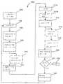
도 27은 본 발명에 따른 경피용 마이크로제트 장치의 사용 방법의 실시예의 흐름도이다.27 is a flowchart of an embodiment of a method of using a transdermal microjet device according to the present invention.
본 발명의 바람직한 실시예에 대해 자세히 참조하면, 실시예들의 예는 첨부된 도면에 도시된다. 본 발명은 바람직한 실시예들과 함께 기술될 것이지만, 본 발명을 이 실시예들에 한정하려는 의도가 아니라는 것을 알 것이다. 반대로, 본 발명은 첨부된 청구항에 정의된 대로 본 발명의 취지 및 범위에 포함될 수 있는 대안 물, 변형물 및 동등물을 포함한다.With reference to preferred embodiments of the present invention in detail, examples of embodiments are shown in the accompanying drawings. While the invention will be described in conjunction with the preferred embodiments, it will be understood that it is not intended to limit the invention to these embodiments. On the contrary, the invention includes alternatives, modifications, and equivalents as may be included within the spirit and scope of the invention as defined in the appended claims.
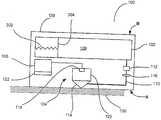
도 1에 도시된 반복성 마이크로제트 장치(100)를 참조하면, 약물 저장소(102)는 유체 속에서 마이크로프로세서(106)에 의해 제어되는 마이크로제트(104)와 연결된다. 마이크로프로세서(106)는 한 줄기(101) 약물을 마이크로제트(104)로부터 생물학적 장벽(130)으로 나가게 하는 마이크로제트(104)를 활성화하도록 프로그램될 수 있다. 참조의 편의를 위해, 반복성 마이크로제트 장치(100)의 표면(A)은 생물학적 장벽(130)을 향해 또는 인접하게 위치한 반복성 마이크로제트 장치(100)의 표면이고 표면(B)은 생물학적 장벽(130)으로부터 가장 멀리 위치한다. 이 방향은 명세서를 통해 일정할 것이고 독자를 적응시키기 위해 주기적으로 사용될 것이다.Referring to the
또한, 반복성 마이크로제트 장치(100)는 반복가능한 활성화를 할 수 있다. 명확하게 하기 위해서, 반복가능한 활성화는 활성화 주기와 비활성화 주기 사이에 장치의 제거, 재충전 또는 보충할 필요 없이 여러 번의, 연속적인 활성화를 의미한다. 예를 들어, 특정한 약물 투여 방법은 5일 동안 매시간에 약물의 특정한 양을 전달하는 것이다. 이 예에서, 반복성 마이크로제트 장치는 힘 발생 장치를 하기와 같이, 반복적으로 활성화시켜, 첫 번째 시간에 소정량의 약물을 전달하는데 필요한 만큼 많은 미세 주사액을 주사하게 된다. 첫 번째 시간의 투여를 완결한 후, 장치는 다음 시간까지 대기할 것이고, 그 후 소정량의 약물을 두 번째 시간에 투여할 것이다. 이 장치는 전체 5일 동안 이런 방식을 이어갈 것이다. 또한, 본 발명에 따라, 마이크로프로세서(106)는 소정의 또는 미리 계획된 타이민에 따라 신호를 발생시키는 간단한 전자 부품 또는 제어 장치이다. 신호의 타이밍은 연속적일 수 있으 나, 연속적인 타이밍에 한정되지 않는다. 그런 후에 제어 장치에 의해 발생된 신호는 마이크로제트를 활성화시켜 한 줄기의 유체를 생물학적 장벽을 향해 나가게 한다.In addition, the
도 2a 및 2b에 도시한 다른 실시예에 따라, 반복성 마이크로제트 장치(200)는 마이크로제트(204)의 배열을 제어하는 마이크로프로세서(206)를 포함한다. 마이크로제트(204)의 배열은 생물학적 장벽의 더 큰 표면을 통해 도 1의 단일 마이크로제트(104)보다 더 많은 양의 물질을 전달할 수 있다. 또한, 마이크로제트(204)의 배열은 생물학적 장벽(130)을 통해 특정한 물질의 투여를 최적화하는 방식으로 여러 물질들 및/또는 물질들을 전달할 수 있다. 바람직하게는 도 1, 2a 및 2b에 도시한 경피용 마이크로제트 장치는 적어도 약 500ms 및 많아야 약 10일인 물질 전달의 지속 시간을 제공한다.In accordance with another embodiment shown in FIGS. 2A and 2B, the
간단하고 명료하게 하기 위해, 다음 설명은 주로 도 1에 도시한 단일 경피용 마이크로제트 장치(100)의 부품을 자세하게 기술할 것이다. 도 2a 및 2b에 도시한 것과 같은 배열 실시예를 참조할 것이고, 부품들의 설명은 각 실시예에 동일하게 적용할 수 있고 단일 마이크로제트를 사용하는 실시예에 한정되지 않는다는 것을 알아야 한다.For simplicity and clarity, the following description will primarily describe in detail the components of the single
경피용 마이크로제트 장치(100)는 하우징(128)을 포함한다. 하우징(128)은 플라스틱, 금속, 세라믹 또는 다른 적절한 생체적합성 재료로 제조될 수 있다. 바람직하게는, 하우징(128)은 폴리머계 재료로부터 제조되어서 경피용 마이크로제트 장치(100)는 반연질이고, 폴리머계 재료가 도포될 때 표면의 외형과 일치될 수 있 으며, 생체적합성이고 약물에 안정하게 된다. 예를 들어, 경피용 마이크로제트 장치(100)가 약물 전달 패치로 제조된다면, 하우징(128)은 약물이 도포되는 위치에서 신체의 외형과 일치하도록 휠 수 있는 것이 유리할 것이다. 게다가, 경피용 마이크로제트 장치(100)는 일회용이고 제조 비용이 낮은 것이 유리할 것이다. 그러나, 폴리머가 아닌 재료로 경피용 마이크로제트 장치(100)를 제조하면, 예를 들어, 경피용 마이크로제트 장치(100)는 살균될 수 있거나 재사용될 수 있어서 유익할 것이다. 부품들이 단일 하우징에 함유되지 않도록 경피용 마이크로제트 장치(100)를 제조하는 것이 더욱 바람직할 것이다. 이런 실시예에 따라, 마이크로프로세서는 저장소로부터 분리될 수 있고, 생물학적 조직과 접촉하도록 형성된 전달 부분으로부터 모두 분리될 수 있다. 이런 실시예에서, 부품; 마이크로프로세서, 저장소 및 전달 부분은 유체에서 전기적이거나 모두가 서로 연결된다.The
도 1에 도시한 저장소(102)는 마이크로제트(104)로부터 분출되는 물질을 수용하도록 형성된다. 이후에, 저장소(102)에 저장되고 마이크로제트로부터 분출된 물질은 주사액(108)으로 불릴 것이다. 통상적으로 주사액(108)은 주사시에 액체 형태이고 약물 조성물, 생리식염수, 유체 매질에서 약물의 에멀젼, 유체 매질에서 약물의 서스펜션, 유체 매질 속의 약물 코팅 리포좀, 유체 매질 속의 약물 또는 약물 코팅 미립자 등일 수 있다.The
바람직한 실시예에 따라, 저장소(102)는 가압될 수 있어서 안에 함유된 주사액(108)은 저장소(102)에서 빠져나온다. 선택적으로, 주사액(108)은 펌프(132)에 의해 저장소(102)로부터 활발하게 빠져나올 수 있다.According to a preferred embodiment, the
도 3에 도시한 한 실시예에 따라, 저장소(102)의 주사액(108)의 가압은 플런저(304)에 압축력을 가하는 스프링(302)에서 발생할 수 있다. 스프링(302)은 한 말단부는 저장소(102)의 내벽에 대해 다른 말단부는 플런저(304)에 대해 위치할 수 있다. 저장소(102)가 주사액(108)으로 가득 찼을 때, 스프링(302)은 가압되어 플런저(304)에 대해 압력을 가한다. 경피용 마이크로제트 장치(100)를 사용하는 동안 주사액(108)은 하기한 대로 발사되고, 주사액(108)의 부피는 저장소(102) 내에서 감소되고, 스프링(302)은 플런저(304)를 움직여, 저장소(102)의 작업 부피를 감소시킨다. 따라서, 주사액(108)은 가압 상태로 존재하며 저장소(102)로부터 자극된다. 당업자는 스프링(302)의 크기와 속도는 특정한 저장소 부피, 주사액의 밀도, 주사액의 점도 등의 상태를 만족하도록 선택될 수 있어서 저장소(102)에 주사액(108)의 전체 부피에서 바람직한 압력을 발생시킨다. 선택적으로, 저장소(102)의 가압은 플런저(304)를 구동하도록 형성된 고압 가스를 통해 성취될 수 있다. 따라서, 고압 가스는 플런저(304)를 움직이는 힘을 제공하여, 충분한 압력하에서 주사액(108)을 보관하는 저장소(102)의 작업 부피를 감소시킨다.According to one embodiment shown in FIG. 3, pressurization of the
도 4에 도시한 또 다른 실시예에서, 저장소(102)는 팽창가능한 엘라스토머형 재료로 제조된 풍선 타입 공기주머니(306)를 수용할 수 있다. 풍선형 공기주머니(306)은 주사액(108)이 채워질 때 팽창한다. 팽창된 풍선형 공기주머니(306)는 화살표 방향으로 힘을 제공하여, 공기주머니(306)로부터 주사액(108)을 나오게 한다. 선택적으로, 저장소(102) 자체는 채워질 때 팽창하는 엘라스토머형 재료로 형성될 수 있어서 저장소(102)의 내용물을 저장소 밖으로 나오게 하는 힘을 제공할 수 있 다.In yet another embodiment, shown in FIG. 4, the
바람직한 실시예에서, 저장소(102)는 도 5에 도시한 대로 하나 이상의 내부 챔버로 분리될 수 있다. 많은 경우 약물 성분은 건조 분말 형태 또는 다른 형태로 저장된다면 더 긴 저장성을 가진다. 따라서, 저장소(102)의 성분을 각각의 부분에 보관하는 것이 바람직할 것이다.In a preferred embodiment, the
따라서, 도 5의 저장소 칸막이(320)는 저장소를 둘 이상의 개별 챔버(324)로 나눌 수 있다. 따라서, 둘 이상의 주사액 성분은 구별되게 보관할 수 있다. 도 5는 두 개의 챔버를 도시하나 당업자는 저장소(102)는 동일한 부피를 가진 많은 챔버 또는 다른 부피를 가진 많은 챔버로 나뉠 수 있고 이의 각각은 한 번 또는 각각의 횟수로 결합될 수 있어서 다른 투여 간격에서 주사액 투여의 여러 단계를 형성한다.Thus, the
바람직한 실시예에 따라, 저장소(102)는 적어도 약 100㎕ 및 많아야 약 500ml의 부피를 가진다. 다른 실시예에서, 저장소(102)의 부피는 적어도 약 150㎕ 및 많아야 약 1ml이다. 다른 실시예에서, 저장소(102)의 부피는 적어도 약 200㎕ 및 많아야 약 750㎕이다.According to a preferred embodiment, the
저장소 칸막이(320)는 투여 전에 파열 장치(322)에 의해 파열되도록 형성되어 분리된 저장소에 수용된 조성물은 투여를 준비하기 위해 혼합될 수 있다. 바람직하게는 저장소 칸막이(320)는 폴리에틸렌, 폴리스티렌, 폴리에틸렌테레프탈레이트(PET)와 같은 생체적합성 폴리머 박막 및 폴리다이메틸실록산(PDMS)와 같은 엘라스토머 폴리머로 제조될 수 있으나, 당업자는 임의의 얇고, 비흡수성인 약물 안정 막은 저장소를 여러 부분으로 분리하는데 사용될 수 있다는 것을 알 것이다.The
예를 들어, 파열 장치(322)는 저장소 챔버의 하나에 위치한 공일 수 있다. 사용시에, 반복성 마이크로제트 장치(100)를 흔들거나 조작하면, 공은 장치로부터 분리되어 움직여 저장소 칸막이(320)에 충격을 가하여, 저장소 칸막이(320)를 파열시켜 저장소 챔버(324 및 326)에 수용된 다른 조성물들을 혼합시킨다. 저장소 칸막이(320)의 파열과 함께, 공은 약물 조성물의 혼합을 용이하게 할 수 있어서, 투여 전에 주사액을 적절하게 혼합시킨다.For example, the
다른 실시예에 따라, 파열 장치(320)는 마이크로프로세서(106)에 의해 제어되는 장치일 수 있다. 예를 들어, 이 파열 장치(302)는 압전성 장치일 수 있다. 이런 실시예에 따라, 마이크로프로세서(106)는 전원으로부터 압전성 파열 장치까지 전압 공급량의 전달을 제어한다. 압전성 파열 장치는 교류의 사용시 유체 매질에 초음파와 같은 기계적 압력파를 만든다. 이런 기계적 압력파는 저장소 칸막이를 파열시키는 역할을 한다.According to another embodiment, the
이런 실시예에 따라, 저장소는 여러 개의 저장소로 나뉠 수 있다. 마이크로프로세서(106)는 저장소 칸막이(320)의 파열 시기와 순서를 제어할 수 있어서 특정한 저장소 칸막이를 파열시켜, 혼합하기 위해 조성물을 배출시킨다. 이런 방식으로, 통상적으로 투여될 조성물의 단지 일부, 즉, 통상적인 투여량은 혼합되어 조성물의 잔존량은 개별 저장소에 안정한 개별 형태로 존재한다. 그 결과, 반복성 마이크로제트 장치(100)는 처리 화합물을 개별적으로 수용할 수 있어서, 오랜 기간 동안 치료제의 반복적 전달을 위해 오랜 시간 동안 유효하게 존재할 수 있다.According to this embodiment, the reservoir may be divided into several reservoirs. The
마이크로프로세서 제어 파열 장치(320)는, 예를 들어, 마이크로프로세서(106)에 의해 발생되는 전기 충격일 수 있다. 각각의 개별 저장소 칸막이(320)는 활성화될 때, 반복성 저장소 칸막이를 파열시키는 전극을 포함할 수 있어서, 투여를 위해 조성물들을 연속적으로 혼합시킨다. 선택적으로, 파열 장치(320)는, 예를 들어, 찌르기, 비틀기, 충격파, 폭발 등과 같은 저장소 칸막이(320)의 물리적 파열일 수 있다. 파열 장치는 비흡수성 저장소 칸막이의 원상태를 파열 또는 파손할 수 있는 장치일 수 있다.The microprocessor controlled
주로 의학적 용도에서, 환자의 치료는 의사의 처방이 아닌 불법일 수 있는 약물을 필요로 한다. 이런 약물들의 일부는 중독성일 수 있으며 처방에 의하지 않고 사용하기 위해 개인들이 많이 찾을 수 있다. 경피용 마이크로제트 장치(100)는 반복적이고 지속적인 투여를 위해 상당량의 이런 약물 성분을 저장할 수 있기 때문에, 일부 개인들은 불법적인 용도로 저장소(102)로부터 약물 성분을 추출하려고 할 것이다. 따라서, 도 6에 도시한 대로 경피용 마이크로제트 장치(100)에 대항 저장소(350)를 포함하는 것이 바람직할 것이다. 길항제 저장소(350)는 저장소(102)와 연결되고 바람직하게는 약물 성분 또는 성분들, 즉 저장소(102)에 함유된 주사액(108)에 대한 길항제(352)를 함유한다.In primarily medical use, the treatment of patients requires drugs that may be illegal rather than a doctor's prescription. Some of these drugs can be addictive and can be found by many individuals for use without prescription. Because the
길항제 저장소(350)는 쉽게 파괴되도록 설계되어, 경피용 마이크로제트 장치(100)가 조작되거나 변형될 때 저장소(102)로부터 주사액(108)을 추출하기에 충분한 방식으로 내부로부터 길항제(352)를 배출시킨다. 길항제 저장소(350)가 파괴될 때, 길항제(352)는 배출될 것이고, 주사액(108) 약물 성분들은 불활성화될 것이다.The
길항제 저장소(350)는, 예를 들어, 저장소(102)를 둘러싸도록 위치하고 저장소(102)보다 쉽게 파괴될 재료로 제조되는 저장소일 수 있다. 선택적으로, 도 7에 도시한 대로, 길항제 저장소(350)는, 예를 들어, 저장소(102) 도처의 격자형 작은 주머니 구조물일 수 있고 파괴 지역(354)이 형성될 수 있어서 이 파괴 지역(354)은 저장소(102)가 파괴되기 전 물리적 조작에 반응하여 파괴되어서, 길항제를 주사액에 배출시켜 주사액(108)을 효과가 없게 만들 것이다.The
도 8에 도시한 대로, 또 다른 실시예에서, 길항제 저장소(350)는, 예를 들어, 여러 개의 미세구(356)일 수 있다. 여러 개의 미세구(356)는 저장소(102)의 과다한 조작에 의해 파괴되어, 길항제를 배출시키도록 제조될 수 있다.As shown in FIG. 8, in another embodiment, the
도 1을 다시 참조하면, 저장소(102)는 공급 라인(110)을 통해 마이크로제트(104)와 유동적으로 연결된다. 공급 라인(110)은 튜브, 챔버, 하우징(128)의 박판의 그루브(아래 상세하게 설명)일 수 있어서, 박판이 결합될 때 저장소(102)와 마이크로제트(104) 사이에 통로가 형성되거나 저장소(102)와 마이크로제트(104) 사이에 주사액(108)을 통과시키는 장치를 형성하는 다른 형태가 형성된다.Referring back to FIG. 1, the
공급 라인(110)은 밸브(112)를 포함할 수 있다. 밸브(112)는 바람직하게는 한방향 밸브여서 주사액(108)의 흐름이 마이크로제트(104)를 향하는 방향으로 흐름을 제한하고 역방향, 저장소(104)를 향하는 방향으로 흐름을 제한한다. 공급 라인(110)은 마이크로제트(104)의 노즐까지 연장되어 유동적으로 연결된다.
바람직한 실시예에서, 공급 라인(110)은 공급 라인(110)에 압력을 제한하는 압력 제어기(116)를 포함한다. 주사액(108)은 상기한 대로, 저장소(102)에 노즐 (114)에서의 소정의 압력보다 더 높은 압력까지 가압하에서 보관될 수 있다. 따라서, 압력 제어기(116)는 공급 라인(110)에 하류 압력을 제어하는 작용을 하여 노즐(114)에서 주사액(108)의 압력은 적절한 수준으로 유지된다. 적절한 수준은 노즐(114)에 대해 보다 상세하게 기술한 대로 노즐(114)을 주사액(108)으로 채우나, 주사액(108)을 노즐(114) 내에 유지하는 힘을 초과하지 않는 압력으로 당업자에 의해 인식될 것이다.In a preferred embodiment,
도 1의 마이크로제트(104)는 이제 기술될 것이나, 설명은 도 2a 및 2b에 도시한 것과 같은 배열 실시예의 마이크로제트(204)에 동일하게 적용할 수 있을 것이다. 일반적으로 마이크로제트(104)는 힘 발생 장치(118), 챔버(120) 및 노즐(114)를 포함한다.The
도 1의 힘 발생 장치(118)는 일반적으로 반복성 마이크로제트 장치(100) 내에 위치하여 장치(118)로부터 발생된 힘은 반복성 마이크로제트 장치(100)의 측면(A)을 향하게 된다. 일반적으로, 각각의 마이크로제트(104)는 도 1에 도시한 대로 각각의 힘 발생 장치(118)를 포함할 수 있다. 선택적으로, 도 9에 도시한 대로 마이크로제트(360a-360e)의 그룹은 하나의 힘 발생 장치(118)에 의해 작동할 수 있다. 사용시에, 힘 발생 장치(118)는 일반적으로 챔버(120) 내의 압력을 변화시키는 작용을 하여, 챔버(120) 내의 주사액(108)을 노즐(114)을 향해 가속시킨다. 힘 발생 장치의 활성화 후에, 가속된 주사액은 각 노즐(114)로부터 분출되어, 노즐로부터 분출된 한 줄기의 주사액을 생산한다. 바람직한 실시예에서, 한 줄기의 주사액은 주사액의 적어도 약 1pl 및 많아야 약 800nl을 함유한다. 보다 바람직한 실시예 에서, 한 줄기의 주사액은 주사액의 적어도 약 100pl 및 많아야 약 1nl을 함유한다. 바람직한 실시예에 따라, 힘 발생 장치는 적어도 약 5ns 및 많아야 약 10㎲의 속도로 챔버 내에서 펄스 폭 또는 압력 변화를 일으킨다. 다른 실시예에서, 펄스 폭은 적어도 약 0.5㎲ 및 많아야 약 10㎲이다. 또 다른 실시예에서, 펄스 폭은 약 1㎲ 및 많아야 약 3㎲이다. 바람직한 실시예에서, 힘 발생 장치는 많아야 초당 약 100펄스를 발생시킨다. 보다 바람직한 실시예에서, 힘 발생 장치는 초당 적어도 약 5펄스 및 많아야 약 15펄스를 발생시킨다.The
실시예에 따라, 힘 발생 장치(118)는 도 10에 도시한 대로 압전성 장치(400)이다. 압전성은 기계적 응력이 결정에 가해질 때 전압을 발생시키거나 반대로 전압이 결정에 가해질 때 기계적으로 응력을 받는 유전체 결정이다. 압전성 장치는 주지되어 있고 압전성의 작동은 당업자에게 명백할 것이다. 압전성 장치(400)는 마이크로제트(104)의 말단 측면(B)을 향해 위치된다. 마이크로제트(104)의 말단벽(B)은 압전성 장치(400)에 의해 발생된 기계적 힘을 견디도록 제조되어 벽은 압전성 장치(400)가 기계적으로 응력을 받을 때 휘지 않는다. 그 결과, 압전성 장치(400)의 기계적 응력 또는 변형은 근접한 방향(A)에서 노즐(114)을 향해 집중된다. 압전성 장치(400)는 플런저로 작동하도록 제조되어, 기계적 변형이 일어나는 동안 근접한 방향에서 주사액(108) 내의 압력 변화를 일으켜, 노즐(114)로부터 분출된 한 줄기의 주사액(402)을 발생시킨다.According to an embodiment, the
하기에서 상세하게 기술되는 마이크로프로세서(106)는 도 10의 회로(124)를 통해 압전성 장치(400)에 연결된다. 사용시에, 주사액(108)의 투여는 하기에 상세 하게 기술된 대로 계획되거나 요구되는 경우, 마이크로프로세서(106)는 전원(122)에 저장된 전압의 압전성 장치(400)에 대한 공급을 제어한다. 전압에 반응하여, 압전성 장치(400)는 기계적으로 응력을 받아 변형되고 챔버(120)에 압력 변화를 일으킨다(도 1).The
도 11에 도시한 실시예에 따라, 한 압전성 장치(410)는 여러 개의 노즐(412)을 작동시킬 수 있다. 저장소(102)의 주사액(108)을 투여하는 동안, 주사액(108)의 부피는 감소한다. 부피 감소에 따라, 압전성 장치(410)에 가해진 전압은 증가하여, 압전성 장치(410)의 더 큰 물리적 변형이 발생한다. 압전성 장치(410)의 더 큰 물리적 변형은 저장소(102) 내 주사액의 부피 감소와 연관이 있어서, 상대적인 동일 압력 변화가 저장소(102) 내에 발생되어, 주사액의 일정하고 예측가능한 사용 및 전달을 위해 노즐로부터 일정한 분출력의 주사액을 발생시킨다.According to the embodiment shown in FIG. 11, one
도 12의 압전성 마이크로제트(420)의 배열을 가진 한 실시예에 따라, 회로(424)는 각각의 마이크로제트(420)에 독립적으로 결합할 수 있다. 따라서, 마이크로프로세서(206)는 각각의 압전성 장치(420)의 변형 타이밍 및 순서를 개별적으로 제어할 수 있다. 그 결과, 주사액(208)의 투여 패턴은 필요한 주사액의 형태, 예를 들어, 당뇨병 치료를 위한 인슐린에 따라 최적의 투여 결과를 위해 제어될 수 있다. 투여 패턴은 전신 순환계 속으로 흡수 및/또는 분산을 최적화하고, 특정한 환자에게 맞춰진 생물학적 장벽 자극 등을 최소화하도록 변형될 수 있어서, 환자 적응성, 약물 효과 및 유효성은 최적화된다.According to one embodiment with the arrangement of
다른 실시예에 따라, 힘 발생 장치는 도 13에 도시한 대로, 상 변화 장치 (430)일 수 있다. 상 변화 장치(430)는 두 개의 전극(432 및 434)을 포함한다. 전극(432 및 434)는 마이크로제트(104)의 말단부를 통과하고 챔버(120)로 튀어나온다. 챔버(120)는 작동 유체(436)를 수용하는 완전히 밀폐된 챔버이다. 챔버(120)의 말단면과 측면은 상 변화 장치(430)에 의해 발생된 힘을 견디도록 제조되었으나, 챔버의 근접 말단부는 유연막(438)이다. 유연막(438)은 챔버(120) 속의 작동 유체(436) 및 노즐에 함유된 주사액(108)에 대해 비침투성인 것이 바람직하고, 두 조성물은 혼합되지 않는다.According to another embodiment, the force generating device may be a
작동 유체(436)는 쉽게 파괴되고 전극(432 및 434) 상의 전하의 차이의 증가에 따라 빠르게 증발하는 유체이다. 작동 유체(436)는 통상적으로 함염 유체를 포함하나 이에 한정되지 않는 도전성 이온성 유체이고, 수용성 금속 헬라이드, 즉, 염화칼륨, 염화칼슘 등과 같은 물속의 다른 염액들이 사용될 수 있다. 또한, 낮은 용융점을 가진 유전 물질들은 불화탄소와 같은 작용 유체(436)로 사용될 수 있다.The working
다른 실시예에 따라, 작동 유체(436)는 주사액일 수 있다. 따라서, 유연막(438)은 전체 챔버(120)로서 필요하지 않을 수 있고 노즐(114)은 상 변화 장치의 활성화 후에 완전히 주사되는 유체로 채워진다.According to another embodiment, the working
유체의 소정량의 부피는 유체가 기체 형태로 전환될 때 크게 증가하기 때문에, 고정된 부피의 챔버에 소정량의 유체를 기화면 챔버의 압력을 크게 증가시킬 것이다. 그런 후에, 유연막(438)은 근접한 방향으로 변형되어, 노즐(114)의 부피를 감소시킨다. 그 결과, 주사액(108)은 보다 상세하게 기술한 대로, 근접한 방향으로 힘을 받고 노즐(114)로부터 분출된다.Since the volume of the predetermined amount of fluid increases greatly when the fluid is converted to gaseous form, the predetermined amount of fluid in the fixed volume chamber will greatly increase the pressure in the chamber. Thereafter, the
마이크로프로세서(106)는 회로(124)를 통해 상 변화 장치(430)와 전기적으로 연결된다. 상기한 대로 압전성 장치의 활성화와 유사하게, 마이크로프로세서(106)는 상 변화 장치(430)의 작동을 제어할 수 있다. 작동 유체(436)의 기화 후에, 작동 유체(436)는 유체로 재형성되고 반복성 기화가 될 수 있어, 반복성 마이크로제트를 발생시킨다. 도 14의 마이크로제트(204)의 배열을 사용하는 한 실시예에서, 마이크로프로세서(206)는 상 변화 장치(440a-440d)의 발사 타이밍 및 순서를 제어한다. 한정하지 않는 예로서, 상 변화 장치는 노즐에 충전된 생리식염수에 침지된 한 쌍의 전극일 수 있다. 이 실시예에 따라, 대략 지름이 1mm인 스테인리스 강철 주사 바늘은 접지 전극을 형성할 수 있고 지름이 대략 25㎛인 텅스턴 와이어는 양극을 형성할 수 있다. 한 말단부에 대략 30㎛ 지름의 개구부를 가진 유리캡은 노즐을 형성할 수 있다. 이 유리캡은 주사기-와이어 전극쌍을 덮어서 전극쌍은 유리캡의 생리식염수에 침지된다. 그런 후에, 전위차가 양극-음극 전극쌍에 가해질 때, 생리식염수는 파괴되어 상 변화를 일으켜서 노즐/캡 내의 압력 변화를 일으킨다.The
다른 실시예에서, 도 13의 작동 유체(436)는 작동 유체의 화학적 및 물리적 특성에 의해 주사액(108)으로부터 분리되어 보존될 수 있어서, 막이 필요 없다. 따라서, 작동 유체는 주사액(108)과 혼합될 수 있어서 두 액체는 혼합되지 않는다. 따라서, 유연막은 필요하지 않다.In another embodiment, the working
도 15에 도시된 다른 실시예에 따라, 단일 상 변화 장치(450)는 여러 개의 노즐(452)를 작동시킬 수 있다. 상 변화 장치(450)는 적어도 두 개의 전극(454 및 456)을 포함한다. 전극(454 및 456) 주위는 유연막(460)에 의해 밀폐된 부피에 수 용된 작동 유체(458)이다. 주사액(108)을 투여하는 동안, 저장소(462) 내의 주사액(108)의 부피는 감소한다. 따라서, 노즐(452)로부터 일정한 분출력의 주사액을 발생시키기 위해, 상응하는 더 큰 힘은 상 변화 장치(450)에 의해 발생되어, 유연막(460)을 더 많이 교체한다. 따라서, 여러 개의 노즐(452)은 저장소(462)에 함유된 주사액의 양과 상관없이 주사액의 반복적 분출력을 가진 하나의 상 변화 장치(450)에 의해 작동될 수 있다.According to another embodiment shown in FIG. 15, the
본 발명의 상 변화 장치는 일반적으로 적어도 약 500V 및 많아야 약 10kV의 고압에서 작동한다. 상 변화 장치는 적어도 약 1kV 및 많아야 약 6kV의 전압에서 작동하는 것이 바람직하다. 다른 실시예에서, 본 발명의 상 변화 장치는 적어도 약 3kV 및 많아야 약 6kV의 전압에서 작동한다. 전압은 적어도 약 5ns 및 많아야 약 10㎲에서 맥동한다. 다른 실시예에서, 전압은 적어도 약 0.5㎲ 및 많아야 약 5㎲에서 맥동한다. 또 다른 실시예에서, 전압은 적어도 약 1㎲ 및 많아야 약 3㎲에서 맥동한다.Phase change devices of the present invention generally operate at high pressures of at least about 500V and at most about 10 kV. The phase change device is preferably operated at a voltage of at least about 1 kV and at most about 6 kV. In another embodiment, the phase change device of the present invention operates at a voltage of at least about 3 kV and at most about 6 kV. The voltage pulsates at least about 5 ns and at most about 10 mA. In another embodiment, the voltage pulsates at least about 0.5 kV and at most about 5 kV. In yet another embodiment, the voltage pulsates at least about 1 kV and at most about 3 kV.
유연막(438 및 460)은 폴리다이메틸실록산(실리콘 고무), 불소폴리머(칼레즈) 등과 같은 낮은 영률의 엘라스토머 재료로 제조되는 것이 바람직하다. 바람직하게는 유연막(438 및 460)의 두께는 적어도 약 0.1㎛ 및 많아야 약 100㎛이다. 다른 실시예에서, 유연막(438 및 460)의 두께는 적어도 약 0.5㎛ 및 많아야 약 50㎛이다. 또 다른 실시예에 따라, 유연막(438 및 460)의 두께는 적어도 약 1㎛ 및 많아야 약 10㎛이다.The
또 다른 실시예에 따라, 힘 발생 장치(118)(도 1)는 도 16에 도시한 대로 솔 레노이드와 같은 전자기 작동 장치(500)일 수 있다. 전자기 작동 장치(500)는 하기한 대로 마이크로프로세서(106)로부터의 정보에 반응하여 작동하여, 플런저(502)는 환자에게 투여하기 위해 주사액(108) 및 주사액(108)의 제트 분출물(504)을 이동시키는 챔버(120)에서 화살표로 나타낸 가까운 A 방향으로 이동한다. 전자기 작동 장치(500)는 당업자가 알 것이므로 더 이상 상세하게 설명하지 않는다.According to yet another embodiment, the force generating device 118 (FIG. 1) may be an
또 다른 실시예에 따라, 힘 발생 장치(118)(도 1)는 도 17에 도시한 대로 플런저(512)를 작동시키는 스프링 장치(510)일 수 있다. 이 실시예에 따라, 챔버(120)의 가까운 말단부는 노즐(114)부분을 챔버(120)로부터 분리시키는 막이 없이개방될 수 있다. 챔버(120)와 노즐(114) 모두는 주사액(108)로 채워진다. 따라서, 챔버(120)의 주사액(108)에 발생된 힘은 노즐(114)의 주사액(108)을 통해 전파되어 아래에 보다 상세하게 설명한 대로 노즐(114)로부터 주사액(108)의 제트 분출물(514)을 나오게 한다.According to yet another embodiment, the force generating device 118 (FIG. 1) may be a
본 발명의 또 다른 실시예에서, 힘 발생 장치(118)(도 1)는 활성화되었을 때, 플런저를 이동시켜 노즐(114)로부터 주사액(108)을 교환하는 고압 기체일 수 있다. 이 실시예에 따라, 마이크로프로세서(106)(도 1)는 상기한 적절한 시기 및/또는 순서에 따라 주사액(108)의 투여를 위한 한 줄기의 주사액(108)을 발생시키기 위해 고압 기체의 이동을 제어한다.In another embodiment of the present invention, the force generating device 118 (FIG. 1) may be a high pressure gas that, when activated, moves the plunger to exchange the injection liquid 108 from the
또 다른 실시예에서, 힘 발생 장치(118)는 폭발성 장치일 수 있다. 예를 들어, 폭발성 장치는 전압이 전달되거나 다른 형태의 발화원이 전달됨에 따라 폭발을 일으겨 발생시키는 화학물질의 혼합물을 포함할 수 있다. 그런 후에 폭발은 챔버 (120) 내에 압력 변화를 일으켜 주사액을 노즐(114)로부터 인접한 생물학적 조직으로 이동시킨다.In yet another embodiment, the
도 1의 챔버(120)는 통상적으로 PDMS와 알려진 폴리다이메틸실록산 또는 실리콘으로 제조하는 것이 바람직하나, 다른 폴리머, 세라믹 또는 금속 재료가 사용될 수 있다. 챔버(120)의 지름은 적어도 약 0.1㎛ 및 많아야 약 500㎛이다. 보다 바람직하게는, 챔버(120)의 지름은 적어도 약 0.5㎛ 및 많아야 약 100㎛이다. 가장 바람직하게는, 챔버(120)의 지름은 적어도 약 1㎛ 및 많아야 약 10㎛이다.The
도 1을 참조하면, 챔버(120)는 마이크로제트(104)의 노즐(114)과 유동적으로 연결된다. 힘 발생 장치(118)가 챔버(120)와 노즐(114) 내에 압력 변화 및/또는 부피 변화를 일으킴에 따라, 노즐(114)로부터 주사액(108)이 분출되고, 챔버(120) 및 노즐(114)은 연속적인 작동을 준비하기 위해 주사액(108)으로 재충전되어 반복적인 마이크로제트를 생산한다. 힘 발생 장치(118)의 작동 후에, 챔버(120)는 반복적 마이크로제트 장치(100)가 작동하는 동안 저장소(102)로부터 주사액이 재충전된다.Referring to FIG. 1, the
상기한 대로, 본 발명의 실시예는 저장소(102)와 노즐(114)을 유체 전달 수단과 유지하는 공급 라인(110)을 사용한다. 또한, 상기한 대로, 저장소(102)는 가압될 수 있거나 펌프(132)를 포함할 수 있어서, 주사액(108)은 공급 라인(110)으로 내려가 노즐(114) 속으로 들어가서, 주사액(108)을 각각 분출한 후 노즐(114)과 챔버(120)를 재충전한다. 선택적으로, 공급 라인(110)은 노즐(114)보다는 챔버(120)와 결합되어 챔버(120)를 비운다.As noted above, embodiments of the present invention employ a
바람직한 실시예에서, 챔버(120) 및/또는 노즐(114)의 교차점에서 공급 라인 (110)의 개구부의 지름은 노즐(114)의 개구부보다 상당히 작아서 역방향에서 주사액(108)의 공급 라인(110) 속으로의 흐름은 약화된다. 또한, 마이크로제트(104)가 작동하는 동안 역방향으로 주입 라인(110)으로부터 주사액(108)을 편향시키도록 위치된 노즐(114) 속의 공급 라인(110)의 개구부 위에 위치한 도 1의 전향판(134)이 있을 수 있다. 다른 실시예에 따라, 밸브(112)(도 1)는 공급 라인(110)이 노즐(114)을 대면하는 지점에 위치할 수 있어서 주사액(108)은 마이크로제트(104)가 작동하는 동안 역방향으로 공급 라인(110)에 들어가지 않는다.In a preferred embodiment, the diameter of the opening of the
다른 실시예에 따라, 주사액(108)은 저장소(102)가 가압되지 않는다면 모세관 작용에 의해 노즐(114)과 챔버(120)를 다시 채운다.According to another embodiment, the
도 9의 다른 실시예에서, 챔버(120)의 먼 말단부는 저장소(102) 속으로 연장되고, 저장소(102) 속에 개구부를 갖거나 챔버(120) 및 저장소(102) 사이에 반유연막을 가진다. 힘 발생 장치(118)는 마이크로제트(104)로부터 분출물(180)을 분출하기에 충분한 주사액(108)에 압력 차이를 일으키기 때문에, 주사액은 개구부(182)를 통해 챔버(120)에 들어가 저장소(102)의 압력으로 챔버 내의 압력을 균일하게 한다.In another embodiment of FIG. 9, the far end of
도 11 및 15에 도시한 대로, 또 다른 실시예에 따라, 주사액을 수용하기 위한 저장소는 또한 챔버로 작용할 수 있다.As shown in FIGS. 11 and 15, according to another embodiment, a reservoir for containing the injection liquid may also act as a chamber.
도 18은 노즐(114)의 일반적인 형태를 도시한다. 노즐(114)의 먼 말단부는 챔버(120)과 결합되고 노즐(114)의 가까운 말단부는 생물학적 장벽(130)과 접촉하도록 형성된다. 사용시에, 힘 발생 장치(118)(도 1)는 챔버(120)에 압력 변화를 일 으키기 때문에, 압력 변화는 챔버(120)와 노즐(114) 내의 주사액(108)을 분출물 형태로 노즐(114) 밖으로 나가게 한다. 노즐(114)은 노즐(114)의 가까운 개구부(602)에 대해 더 작은 단면 지름으로 끝이 가늘어지는 것이 바람직하다. 가속되는 주사액(108)의 초기 부피는 노즐(114)이 가깝게 끝이 가늘어짐에 따라 노즐(114의 부피보다 크기 때문에, 주사액(108)은 더 큰 속도로 가속된다. 노즐(114)의 개구부에 도달하자마자, 가속된 주사액은 한 줄기의 유체로서 노즐(114)로부터 분출된다. 다업자는 노즐 크기, 챔버 부피, 주사액의 속도 등은 주사액의 분출물이 소정량의 힘을 갖도록 변형될 수 있어서 주사액의 분출물은 생물학적 장벽(130)을 통과하여 주사액을 인접한 조직에 소정의 깊이로 쌓이게 할 것이다.18 shows a general form of the
도 18의 노즐에 따라, 노즐(114)은 생물학적 장벽(130)을 부드럽게 받칠 수 있는 경우 반이 뭉툭한 가까운 말단부를 갖도록 제조된다. 노즐(14) 내의 주사액(108)은 생물학적 장벽(130)과 접촉한다. 따라서, 힘 발생 장치(118)가 작동할 때, 주사액의 투여량은 노즐(114)의 주사액(108)을 통해 전파되고 인접한 생물학적 장벽(130)의 처음층을 통해 뚫고 나간다.According to the nozzle of FIG. 18, the
도 19에 도시한 대로 실시예에 따라, 노즐(114)의 먼 말단부(604)는 주사액(108)을 통과시키지 않는 조성물 등으로 제조된 코팅을 포함할 수 있다. 예를 들어, 주사액(108)이 친수성 물질이라면, 노즐(114)의 가까운 말단부(604)는 친유성 물질로 코팅되거나 친유성 물질로 제조될 수 있어서, 주사액(108) 노즐(114)의 가까운 말단부(604)를 저항 없이 통과하는 것을 튀겨낸다. 이 실시예에서, 주사액(108)은 장치의 휴식 단계 동안 생물학적 장벽(130)의 표면으로부터 설정된 거리 (h)를 유지한다. 따라서, 주사액(108)이 생물학적 장벽(130)과 접촉하게 놓일 때 생물학적 장벽(130)을 자극하거나 생물학적 장벽(130)에 다른 악영향을 일으키는 경향을 가질 때, 이런 일들은 감소될 것이다. 또한, 이 실시예에 따라, 투여된 주사액(108)의 보다 정확한 양을 예측할 수 있고 전달할 수 있는데 이는 주사액은 투여하는 동안 제트 추진 기류가 아니면 생물학적 장벽(130)을 통과하거나 생물학적 장벽(130)을 들어가서 분산될 수 없기 때문이다.According to an embodiment, as shown in FIG. 19, the
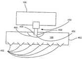
선택적으로, 노즐(114)의 가까운 말단부는 도 20에 도시한 대로, 수렴되는 형태/확산되는 형태(606)를 가질 수 있다. 이 실시예에 따라, 주사액(108)의 위치는 생물학적 장벽(130)으로부터 최적의 거리(h)에서 주사액(608)의 초승달 형태를 유지하도록 결정될 수 있다. 높이(h)는 초승달 형태와 투여된 한 줄기의 주사액(108)을 침투시키는 주사액(608)의 생물학적 장벽(130) 사이의 거리로 결정되고 생물학적 장벽(130)을 설정된 거리에 침투시킨다. 한 실시예에 따라, 높이(h)는 생물학적 장벽의 표면으로부터 적어도 약 0㎛ 및 많아야 약 5000㎛일 수 있다. 다른 예시적 형태에 따라, 예를 들어, 각질층은 약 10㎛-15㎛의 두께이고 상피는 각질층 아래의 약 50㎛-100㎛의 두께이다. 따라서, 상피가 주사액의 표적 지역이라면, 높이(h)는 주사액을 적어도 약 10㎛ 및 많아야 약 500㎛의 거리로 침투시키는 거리로 설정될 수 있다. 다른 실시예에서 주사액은 생물학적 장벽의 표면 아래 적어도 약 25㎛ 및 많아야 약 100㎛의 깊이로 침투한다.Optionally, the near distal end of the
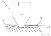
도 21에 도시한 대로 본 발명의 한 실시예에 따라, 노즐(114)은 하우징(128)로부터 거리(h) 만큼 돌출한다. 사용하는 동안, 하우징(128)의 가까운 표면(A)은 도 22a에 도시한 대로 생물학적 장벽(130)을 직접 대면하게 위치할 수 있어서, 노즐(114)은 생물학적 장벽(130)과 바람직한 방향에 자동적으로 위치할 것이다. 또한, 노즐(114)이 하우징(128)의 가까운 표면(A)으로부터 돌출되어 경피용 마이크로제트 장치(100)가 생물학적 장벽(130)을 향해 위치할 때 생물학적 장벽(130)에 장력을 가한다. 생물학적 장벽(130)을 장력 또는 선하중(pre-load) 하에 놓이게 하면 마이크로제트(104)로부터 분출물의 분출을 용이하게 하여 생물학적 장벽(130)을 통과한다. 선하중은 생물학적 장벽(130)으로부터 탄성력을 제거하거나 감소시킨다. 따라서, 생물학적 장벽을 실제로 침투하는 주사액의 정확한 양을 계산할 수 있고 장치는 정확한 투여량을 전달하는데 사용될 수 있다. 그 결과, 공지되고 일정한 접촉 압력은 노즐(114)과 생물학적 장벽(130) 사이에 가해질 것이다. 따라서 사용자는 간단히 하우징(128)의 가까운 면(A)을 생물학적 장벽(130)을 향하게 하면 노즐(114)은 주사액의 최적의 투여를 위해 적절하게 위치될 것이다.According to one embodiment of the present invention as shown in FIG. 21, the
도 22b에 도시한 대로, 다른 실시예에 따라, 하우징(128) 위로 돌출된 노즐(114)의 가까운 말단부는 생물학적 장벽(130)의 처음층 속에 또는 이를 통과하여 위치되는 형태를 가질 수 있다. 사용시에, 마이크로제트(104)로부터 생성된 제 1의 여러 분출 주사액은 생물학적 장벽(130)을 통과하여 또는 이 속에 구멍(190)을 만들고 경피용 마이크로제트 장치(100)를 생물학적 장벽(130)에 가하는 힘은 분출 주사액에 의해 발생된 구멍(190) 속에 노즐(114)의 가까운 선단을 위치시킨다. 따라서, 노즐(114)의 가까운 선단을 생물학적 장벽(130 속에 또는 이를 통과하게 삽입한 후, 노즐(114)의 주사액(108)은 저항 없이 생물학적 장벽(130) 속으로 분산될 수 있다.As shown in FIG. 22B, according to another embodiment, the near distal end of the
노즐(114)은 적어도 약 1㎛ 및 많아야 약 500㎛의 구멍 지름을 가진다. 다른 실시예에 따라, 노즐(114)은 적어도 약 25㎛ 및 많아야 약 250㎛의 구멍 지름을 가진다. 보다 바람직하게는, 노즐(114)은 적어도 약 30㎛ 및 많아야 약 75㎛의 구멍 지름을 가진다.The
노즐(114)은 당업계에 공지된 여러 방법에 의해 제조될 수 있는데, 예를 들어, 한 방법은 유리 튜브를 가열하고 튜브를 당겨 소정의 지름을 얻는 것과 그 후 튜브에 선을 긋고, 구부리고 광택을 내어 노즐을 완성하는 것이다. 다른 보다 바람직한 방법은 노즐을 성형하는 것 또는 매스터 주형으로부터 노즐을 사출성형하는 것을 포함한다. 노즐을 제조하는 또 다른 방법은 포토리소그래픽 가공과 에칭을 사용하는 것을 포함한다. 노즐을 제조하는 다른 방법은 예를 들어, 레이저 드릴링을 포함한다. 이런 방법은 당업계에 주지되어 있고 당업자가 알 수 있어서, 추가 설명은 하지 않겠다. 또한, 당업자는 노즐(114)은 끝이 가늘어지고, 원뿔형이고, 직선형의 복합 형태 등일 수 있다.The
다른 실시예에 따라, 장치는 도 2a에 도시한 대로 마이크로제트(204)의 배열과 노즐(214)의 배열을 갖도록 제조되고, 여러 개의 주사액 물질은 다른 노즐을 통해 전달될 것이다. 이런 실시예에 따라, 각 마이크로제트(204)는 다른 저장소와 연결될 수 있고 또는 다른 그룹의 마이크로제트(204)는 다른 저장소와 연결될 수 있어서 일부 마이크로제트는 특정한 주사액을 주사할 수 있고 다른 마이크로제트는 다른 주사액을 주사할 수 있다.According to another embodiment, the device is manufactured with an arrangement of
도 2b의 마이크로제트(204)의 배열을 가진 또 다른 실시예에 따라, 각 마이크로제트는 개개의 전달 장치(242)일 수 있다. 따라서, 각 전달 장치(242)는 마이크로프로세서(206)에 의해 독립적으로 작동할 수 있다. 게다가, 마이크로프로세서(206)는 전달 장치에 함유된 특정한 주사액이 배출될 때까지 다음 전달 장치의 작동을 개시하는 한 번에 하나의 전달 장치(242)를 작동시키고 그런 후에 각 전달 장치의 주사액이 배출될 때까지 다음 전달 장치의 작동을 시작하도록 프로그램될 수 있다.According to another embodiment with the arrangement of the
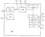
이제 바람직한 마이크로프로세서(106)를 기술할 것이다. 도 23에 도시한 대로, 마이크로프로세서(106)는 중앙처리장치(CPU)(700), 메모리(702), 사용자 인터페이스(704), 통신용 인터페이스 회로(706), 일시적 기억장치(RAM) 및 이런 요소들을 연결하는 버스(704)를 포함한다. 마이크로프로세서(106)는 프로그램될 수 있고 특정한 주사액의 투여 방식에 관한 데이타, 환자 자격, 마이크로제트 작동 패턴, 저장소 혼합 회수 및/또는 조건, 투여량 등에 관한 데이타를 메모리(702)에 저장한다. CPU(700)는 주사액(108)을 투여하기 위해 메모리(702)에 저장된 데이타를 분석하고 수행한다. 또한 메모리(702)는 마이크로제트(104)의 작동 시기와 순서를 제어하여 주사액의 투여를 제어하기 위한 작동 절차(702)를 포함한다. 사용시, 상기한 대로, 어떤 힘 발생 장치(118)가 반복성 마이크로제트 장치(100)의 특정한 실시예에 포함되는 가에 따라, 마이크로프로세서(106)는 작동 유체의 기화를 일으키기 위해 압전성 장치에 대한 전압의 전달, 전극에 대한 전압의 전달을 제어하고, 마이크로제트(104)의 작동을 제어하기 위해 전자석, 고압 기체의 움직임 등을 제어한다. 본 명세서를 통해 마이크로프로세서(106)는 마이크로제트의 활성화를 제어하는 것으로 간주한다. 당업자는 마이크로프로세서는 마이크로제트의 힘 발생 장치에 대한 전력 공급을 제어하는 것을 알 것이다. 예를 들어, 마이크로프로세서는 전원으로부터 힘 발생 장치로 전력의 흐름을 일으켜 힘 발생 장치를 활성화하는 트랜지스터와 같은 스위치를 활성화할 수 있다. 그러나, 독자의 편의를 위해서, 이 과정은 마이크로제트의 마이크로프로세서 제어 활성화로 부를 것이다.The
마이크로프로세서(106)는 마이크로제트의 활성화를 제어하여 특정한 시간 동안 특정한 간격으로 환자에게 치료제의 특정한 투여량을 전달하도록 프로그램될 수 있다. 적절한 시간에, 마이크로프로세서(106)는 처방된 치료제를 '발사' 또는 작동 및 전달하기 위해 마이크로프로세서(104)의 작동을 개시할 것이다. 따라서, 환자는 하루 종일 자동적으로(사람이 더 이상 관여하지 않고) 전신에 최적의 투여량 수준을 유지하는 장치를 통해 이득을 얻을 수 있어서 치료는 환자 상태에 대해 최적의 효과를 가질 수 있다. 또한, 한 줄기의 주사액의 전달 또는 주사는 단지 각질층을 침투하여 치료제를 상피 속에 전달하기 때문에, 신경 말단부가 없는 곳에서, 이 과정은 사용자에게 통증이 없다. 마이크로프로세서(106)는 주사액 성분의 적절한 혼합을 위해 상기한 대로, 저장소(102) 내의 독립 챔버들 사이의 저장소 칸막이(320)(도 5)의 파괴를 제어할 수 있다.The
다른 실시예에 따라, 마이크로프로세서(106)의 메모리(702)는 환자를 위한 치료 방식을 향상시키기 위해서 장래의 분석과 평가를 위해 전달된 주사액의 양, 투여 시기, 투여 횟수 등을 보관한다.According to another embodiment, the
다른 실시예에서, 마이크로프로세서(106)는 또한 사용자 인터페이스(704)를 포함할 수 있다. 사용자 인터페이스(704)는 버튼, 스위치 또는 임의의 시간에 주사액의 투여를 자극하기 위해 사용자에 의해 활성화될 수 있는 다른 장치일 수 있다. 예를 들어, 부스트 버튼(136)은 부스터 버튼 연결 링크(138)를 통해 마이크로프로세서(106)와 연결되도록 위치할 수 있다.In other embodiments,
따라서, 만일 환자 또는 투여자가 임의의 시간에 주사액의 투여량을 전달할 필요가 있다고 결정한다면, 부스트 버튼(136)이 작동될 수 있어서, 프로그램된 투여 방식을 무시하고 주문된 소정의 투여량의 주사액을 전달한다. 이것은 장치가 통증약을 전달하는 데 사용되는 경우에 유익할 수 있는데 이는 통증약의 필요는 소정의 전달 방식의 바깥에서 발생하기 때문이다. 그러나, 사용자 인터페이스 장치(704)와 관련하여, 마이크로프로세서(106)는 안전하게 미리 프로그램될 수 있어서 사용자는 주어진 시간에 많은 횟수로 사용자 인터페이스 장치(704)를 작동시킬 수 있고, 환자는 주사액을 과용하거나 남용하지 않을 것이다. 환자가 사용자 인터페이스 장치(704)를 작동할 수 있는 횟수는 주사액을 이루는 물질, 환자의 연령, 환자의 체중, 환자 상태의 심각성 등에 따라 조절될 수 있다.Thus, if the patient or the administrator decides that it is necessary to deliver the dosage of the injection at any time, the
또 다른 실시예에 따라, 마이크로프로세서(106)는 다른 컴퓨터 시스템과 통신하기 위한 통신 인터페이스 회로(706)를 가진다. 의사, 연구원 등은 컴퓨터, 소형 컴퓨터, 무선 통신 등을 통해 마이크로프로세서(106)와 연결될 수 있고 투여 주기, 각 간격에 전달되는 투여량, 전달되는 투여량의 다양성, 전달되는 전체 투여량 등에 관한 정보에 접근할 수 있다. 또한, 의사 또는 연구원은 메모리(702)에 저장 된 데이타를 다운로드할 수 있거나 투여 방식 또는 작동 순서(716)를 변형할 수 있다. 마이크로프로세서(106)와 연결하는 것은 어떤 질환의 치료를 지속적으로 이해하고 새롭고 나은 치료 물질과 방식을 개발하는데 유용할 수 있다.According to another embodiment,
도 24에 도시한 대로, 다른 실시예에서, 마이크로프로세서(106)는 바이오센서(750)와 연결된다. 바이오센서(750)는 사용자의 신체에 이식될 수 있거나 사용자의 외부에서 사용될 수 있다. 바이오센서(750)는 주사액이 치료, 우회, 변형, 치유, 증대하도록 설계된 생물학적 상태를 탐지하는 센서가 바람직하다. 바이오센서(750)는 하드-와이어 연결, 무선 등일 수 있는 통신 장치(706)를 통해 마이크로프로세서(106)와 연결된다. 바이오센서(750)는 바람직하게는 생물학적 상태를 측정하고 측정 결과를 통신 장치(706)를 통해 마이크로프로세서(106)에 전달한다.As shown in FIG. 24, in another embodiment, the
마이크로프로세서(106)는 바이오센서(750)에 의해 측정된 값을 읽고 소정의 변수 범위 내에서 상태에 반응하고, 마이크로프로세서(106)는 탐지된 상태를 치료하기 위해 사용자에게 주사액을 주사하도록 마이크로제트(104)를 작동시킬 것이다.The
다른 실시예에 따라, 장치(100)는 도 1의 상태 센서(133)를 포함할 수 있다. 상태 센서(133)는 바람직하게는 장치(100)가 생물학적 장벽(130)과 접촉하고 있는지 아니면 향하고 있는 위치에 있는지를 탐지하도록 제조되어 장치(100)가 활성화되면 주사액의 주사를 일으킬 것이다. 만일 장치(100)가 생물학적 장벽(130)으로부터 제거되거나 위치를 벗어나는 경우, 마이크로제트(104)의 활성화는 일어나지 않을 수 있고 주사액이 환자에게 투여되지 않는다. 따라서, 마이크로프로세서(106)와 연결된 상태 센서(133)는 마이크로제트(104)가 장치(100)가 다시 배치될 때까지 활 성되거나 활성화되지 않는 지를 나타내는 피드백을 제공할 수 있다. 또한, 상태 센서(133)는 버저 또는 다른 형태의 경보 장치를 포함할 수 있어서 장치가 위치를 벗어나고 활성화되지 않는다는 것을 환자 또는 주치의(들)에게 전달한다. 상태 센서는, 예를 들어, 온도 센서, 압력 센서 등일 것이다. 다른 실시예에서, 센서(133)는 힘 발생 장치에 의해 발생된 압력을 탐지하도록 제조될 수 있어서, 힘 발생 장치의 기능을 관찰하기 위해 마이크로프로세서에 피드백 장치를 제공한다.According to another embodiment, the
도 1의 마이크로프로세서(106)는 마이크로제트로부터 분출된 주사액의 분출 당 주사 에너지, 주사 속도, 주사 부피, 시간에 따른 약물 용량 전달 형태 등을 제어한다. 또한, 마이크로프로세서(106)는 치료 효과를 극대화하기 위해 시간에 따라 변할 수 있는 투여량을 전달하도록 프로그램될 수 있다. 이것은 성장 호르몬 결핍(GHD)을 위한 인간 성장 호르몬(hGH), 당뇨병을 위한 식사시간 혈당 수준 제어를 위한 인슐린 전달과 같이 생물학적 주기 변화 또는 박동형 전달이 필요한 특정한 상태에 특히 중요할 수 있다.The
도 1을 참조하면, 반복적 마이크로제트 장치(100)는 전원(122)을 포함할 수 있다. 전원(122)은 NiCd, NiMH, LiMnO2 배터리, 일회용 배터리, 충전 배터리 등과 같은 배터리를 포함할 수 있다. 바람직하게는 경량이고, 소형이고, 수명이 길고, 저렴하며 일회용인 배터리는 전원(122)을 포함한다. 그러나, 다른 실시예에서, 전원(122)은 힘 발생 장치(118)와 마이크로프로세서(106)에 전압을 전달하기 위한 다른 허용가능한 형태의 전원일 수 있다.Referring to FIG. 1, the
도 25에 도시한 다른 실시예에 따라, 경피용 마이크로제트 장치(800)는 외부 저장소(802)를 포함한다. 외부 저장소(802)는 노즐(804)에 인접한 홈이 있는 저장소로 제조될 수 있다. 따라서, 외부 저장소(802)는 생물학적 장벽(830)을 통해 전달되는 물질로 채워질 수 있다. 생물학적 장벽(830)을 통해 전달되는 물질은 공급 라인(810)을 통해 저장소(808)에서 외부 챔버로 전달될 수 있다. 사용시에, 경피용 마이크로제트 장치(800)는 생물학적 장벽(830)에 인접하게 위치하고 마이크로제트(812)는 상기한 대로 작동한다. 작동하자마자, 마이크로제트(812)는 한 줄기의 용액을 분출하여, 생물학적 장벽(830)을 통과하여 구멍(814)을 형성한다. 경피용 마이크로제트 장치(800)는 생물학적 장벽(830)에 대해 움직이기 때문에, 마이크로제트(812)의 한 줄기 물질에 의해 발생한 구멍(814)은 외부 저장소(802)에 있는 물질이 이를 통해 저항 없이 분산되는데 이용된다. 또한, 기질은 생물학적 장벽(830)의 침투성을 증가시키는 것을 돕기 위해 생물학적 장벽(830)을 통해 전달되는 물질에 첨가될 수 있다.According to another embodiment shown in FIG. 25, the
선택적으로, 도 25에 도시한 경피용 마이크로제트 장치(800)는 체액을 샘플링하고 수집하고, 생물학적 장벽(830)을 통해 생물학적 표본을 진단하기 위해 사용될 수 있다. 이런 형태에서, 마이크로제트(812)는 상기한 대로 작동하고 통상적으로 생리식염수 형태의 용액을 생물학적 장벽(830) 속으로 주사하나, 당업자는 마이크로제트(812)를 통해 생물학적 장벽(830) 속으로 분출하는데 적합한 임의의 용액이 사용될 수 있다는 것을 알 것이다. 생물학적 유체를 생물학적 장벽(830)을 통해 주사한 후, 생물학적 유체는 주사 제트에 의해 발생된 구멍(814)을 통해 분산된다. 이 생물학적 유체는 수집되고 샘플링되거나 분석될 수 있다. 다른 실시예에서, 마이크로제트(812)는 생물학적 조직 속으로 주사하기 위한 특정물질을 포함할 수 있다. 특정물질을 주사한 후, 특정물질은 특정한 광학 또는 형광 기술을 통해 탐지 또는 측정될 수 있다. 당업자는 많은 다른 화학적, 생화학적 및/또는 생물학적 진단 기술이 사용될 수 있다는 것을 알 것이다.Optionally, the
본 발명의 바람직한 실시예에 따라, 경피용 마이크로제트 장치는 도 26에 도시한 약물 전달 패치(900)로 제조될 수 있다. 약물 전달 패치(900)는 폴리다이메틸실록산(PDMS), 폴리에틸렌, 폴리에틸렌테레프탈레이트(PET), 불화폴리머 등과 같은 생체적합성 및 약물 안정성 물질의 박층(902, 904, 906 및 908)으로 제조되는 것이 바람직하다.In accordance with a preferred embodiment of the present invention, the transdermal microjet device may be manufactured with the
마이크로제트 층(902), 제어 회로층(904) 및 저장층(906)은 통상적으로 바람직하게는 약물 성분을 투여한 후 버릴 수 있는 투여 장치를 포함한다. 마이크로프로세스(908)는 반드시 쓰고 버릴 필요가 없고 투여 장치와 상호작용하도록 조절되는 마이크로프로세서 층에 수용되는 동안 환자는 마이크로프로세서 층(908)을 계속 사용할 수 있고 이 층을 새로운 투여 패치에 재연결할 수 있다. 도 11 및 15에 도시한 대로, 투여 장치(102 및 462)는 각각 마이크로프로세서(106)로부터 분리될 수 있다. 이 실시예에 따라, 제어 장치는 마이크로프로세서(106) 및 힘 발생 장치(410 및 450)를 각각 포함한다. 따라서, 투여 장치를 교환할 때 제어 장치를 계속 사용함으로써, 마이크로프로세서 및 힘 발생 장치 모두를 계속 사용하고, 장치의 쓰고 버릴 수 있는 부분은 투여 장치에 한정된다. 그 결과, 투여 장치의 교환 비용은 저 렴하고 제조 과정은 효율적이다.The
저장소 층(906)은 제어 회로망 층(904)과 결합될 때 주사액 성분을 저장하기 위한 저장소를 형성하는 오목한 지역(910)을 포함하는 것이 바람직하다. 저장소 층(906)은 주사액을 공급하는 마이크로제트(914)를 유지하기 위해 공급 라인(912)을 통해 마이크로제트 층(902)과 유동적으로 결합한다. 제어 회로망 층(904)은 마이크로제트(914)를 활성화하는 전기 회로망(916)을 포함한다. 표면(A)인 마이크로제트 층(902)의 가까운 표면은 사용자의 표면에 경피용 약물 전달 패치(900)를 부착하기 위한 접착제를 포함하는 것이 바람직하다.The
마이크로프로세서 층(908)은 통상적으로 마이크로프로세서(106)를 포함하고 전원(122)을 포함할 수 있다. 마이크로프로세서 층(908)은 마이크로제트(914)의 작동을 제어하기 위한 마이크로프로세서(106)를 수용하도록 제조된다. 마이크로프로세서 층(908)은 제어 라인(918)을 통해 제어 회로망 층(904)과 전기적으로 결합한다. 바람직하게는, 마이크로프로세서 층(908)은 투여 패치에 제거할 수 있도록 부착되게 제조되어서 투여 패치의 주사액(108)이 완전히 분출되거나 특정한 주사액의 투여가 완료된 후 마이크로프로세서(106)를 계속 사용할 수 있다. 따라서, 환자는 추가 주사액을 투여하면서 새로운 투여 패치를 받을 수 있고 마이크로프로세서(908)는 환자에게 고정될 수 있어서 주사액의 투여는 특정한 환자 또는 치료 방식을 위해 미리 프로그램된대로 지속할 수 있다.
전원(122)은 투여 패치 또는 마이크로프로세서 층(908)에 수용될 수 있다. 전원이 투여 패치에 수용될 때, 치료를 완료한 후에 투여 패치와 함께 처리되도록 제조된다. 따라서, 이런 형태에서, 매시간 사용자는 새로운 투여 패치를 받고, 새로운 전원은 제공될 것이어서, 전원은 치료 방식을 통해 부분적으로 사라지지 않을 것이다.The
도 11 및 15에 도시한 대로, 다른 실시예에서, 힘 발생 장치(410 및 450) 각각은 마이크로프로세서 층(908)의 부품으로 제조될 수 있어서 장치는 투여 패치가 제거될 때도 계속 사용할 수 있어서 효율성을 증가시키고 최종 사용자에게 비용을 감소시킨다.As shown in FIGS. 11 and 15, in other embodiments, each of the
바람직하게는 박막층은 함께 결합된다. 박막층은 화학적 결합, 열적 결합 등에 의해 함께 결합할 수 있다. 또한, 패치는 효율적이고 경제적인 형태로 제조되어 내용물의 투여 후 버릴 수 있는 것이 바람직하다.Preferably the thin film layers are bonded together. The thin film layers may be bonded together by chemical bonding, thermal bonding, or the like. It is also desirable that the patch be made in an efficient and economical form so that it can be discarded after administration of the contents.
박막층(902, 904 및 906)은 유연하고, 생체적합성이며, 약물 안정성인 재료로 제조되는 것이 바람직하여서 약물 전달 패치(900)는 신체의 위치에 사용될 수 있고 신체의 외형과 일치할 수 있다. 또한, 경피용 약물 전달 패치(900)는 유연하기 때문에 사용자의 활동을 제한하지 않는다. 다른 실시예에 따라, 경피용 약물 전달 패치(900)는 유연하지 않은 재료로 제조될 수 있다. 따라서, 경피용 약물 전달 패치(900)는 사용 위치의 외형을 그리지 않는다.The thin film layers 902, 904, and 906 are preferably made of a flexible, biocompatible, and drug stable material such that the
경피용 마이크로제트 장치(100)는 접착제에 의해 사용자의 피부에 도포되는 경피용 약물 전달 시스템으로 제조될 수 있다. 다른 실시예에서, 장치는 피부와 접촉하게 위치되고, 벨트, 버클, 고무 밴드 등과 같은 조절가능한 밴드에 의해 제 위치에 부착될 수 있다.The
다른 실시예에 따라, 경피용 마이크로제트 장치(100)는 생물학적 장애, 상처, 질병, 질환 등을 치료하기 위한 약물, 치료액, 생리식염수 등의 소형 도포기 또는 기계적 도포기로 제조될 수 있다. 선택적으로, 경피용 마이크로 장치는 내장, 종양, 뇌척수 경막 및 연막과 같은 생물학적 장벽 등과 접촉하는 이식가능 장치로 제조될 수 있다. 또한, 경피용 마이크로제트 장치는 장기간 이식가능한 지속적 제어형 약물 배출 장치로 제조될 수 있다. 이식가능한 장치는 프로그램된 치료 방식을 변화시키기 위해 이식 장소의 외부에서 무선으로 제어될 수 있다. 상기한 대로, 장치는 정맥 내 약물 전달 시스템 대신에 사용될 수 있다. 이런 실시예에서, 장치는 약물을 경피적으로 상피 속에 전달하는데 사용될 수 있다. 장치는 환자의 피부에 위치할 수 있고 장치 저장소는, 예를 들어, 전통적인 정맥(IV) 내 약물 적하 공급기일 수 있다. 약물은 많은 IV 약물 전달 용도에서 용인될 수 있는 매우 짧은 시간에 상피로부터 정맥으로 분산된다. 또한, 지속적인 정맥 내 치료가 필요한 환자의 경우, 도뇨관의 삽입 위치에서 합병증이 종종 발생한다. 또한, 도뇨관 삽입 위치는 신체로 통하는 주요 감염 경로이다. 본 실시예에 따른 본 발명을 사용하면 전통적인 정맥 내 약물 전달 시스템에 의한 감염 및 다른 합병증에 대한 가능성을 감소시킨다.According to another embodiment, the
본 발명은 약물을 생물학적 조직에 기계적으로 전달하기 위한 장치와 방법에 관한 것이기 때문에 장치는 격막, 공동 작인, 용해도, 전하, 분자량 등과 같은 약물의 물리 화학적 특성과 무관하게 사용할 수 있다. 그러나, 당업자는 피부 침투성을 증가시키기 위해 물질을 주사액에 첨가할 수 있다는 것을 알 것이다. 이런 물질 은 화학적 계면활성제 등일 수 있다.Since the present invention relates to a device and a method for mechanically delivering a drug to biological tissue, the device can be used independently of the physicochemical properties of the drug such as diaphragm, cofactor, solubility, charge, molecular weight and the like. However, those skilled in the art will appreciate that substances may be added to the injection solution to increase skin permeability. Such materials may be chemical surfactants and the like.
도 27은 약물 전달 장치로서 본 발명을 사용하는 방법을 도시한다. 도시된 방법에 따라, 방법은 단계(1002)에서 상태를 진단하고 그 상태에 대한 바람직한 치료법의 관련된 선택하는 것으로 시작한다. 일단 치료법이 선택되면, 주사액(108)이 준비된다. 주사액은 본 발명의 경피용 마이크로제트 장치(100)를 사용하여 투여될 물질이다. 주사액은 약물, 항생 물질, 진통제, 위약, 생리식염수 등일 수 있다. 다음으로, 단계(1006)에서, 주사액은 경피용 마이크로제트 장치(100)의 저장소(102)에 채워진다. 그런 후에 마이크로프로세서(106)는 단계(1008)에서 선택한 특정한 상태와 치료법에 대한 바람직한 투여 방식으로 프로그램된다. 다음으로, 마이크로프로세서(106)가 경피용 마이크로제트 장치(100)의 투여 장치에서 분리되면, 두 개의 부품은 단계(1010)에서, 서로 결합한다. 마이크로프로세서(106)와 투여 장치의 연결 장치는 핀 와이어 연결, 무선 연결 등일 수 있다. 약물 전달 장치는 단계(1012)에서 치료될 생물학적 조직에 사용된다. 장치와 결합하는 생물학적 조직은 종양을 치료하기 위해 종양에 직접 장치를 사용하는 것과 같이, 치료되는 조직일 수 있거나 생물학적 조직은 치료될 조직에 도달하기 위해 주사액이 반드시 넘어야 하는 장벽일 것이다. 예를 들어, 장치의 바람직한 용도가 약물을 환자에게 전신으로 전달하는 것이면, 피부는 넘어야 할 생물학적 장벽일 것이다. 따라서, 장치는 생물학적 조직과 결합하거나 접촉하고 장치는 주사액을 장벽을 넘어 주사하여 전신으로 전달한다.27 illustrates a method of using the present invention as a drug delivery device. According to the method shown, the method begins with diagnosing the condition at
주사액을 생물학적 조직에 투여하는 동안, 주사액의 투여와 관련된 데이타는 단계(1014)에서 기록된다. 통상적으로 기록될 수 있는 데이타는 각 투여 시간, 각 투여량 등을 포함한다. 다른 실시예에서, 장치는 체온, 혈압, 맥박, 혈당 수치와 같은 환자의 생물학적 활동 또는 환자의 다른 생물학적 및/또는 화학적 상태를 관찰하고 기록하는 바이오센서와 같은 센서를 포함할 수 있다. 다음으로, 생물학적 조직의 치료를 담당하는 의사 또는 연구원이 원한다면, 장치와 전자적으로 연결하여 실시간으로 및/또는 단계(1016)에 도시한 대로, 주사액을 투여하는 동안 임의의 시간에 기록되는 데이타를 받을 수 있다. 의사 또는 연구원은 단계(1018)에서, 주사액을 투여하는 동안 마이크로프로세서(106)와 전자적인 연결을 통해 투여 방식을 바꿀 수 있다. 다음으로, 주사액의 투여는 단계(1020)에서, 투여 방식을 수행한다.While the injection is administered to biological tissue, data related to the administration of the injection is recorded at
만일, 주사액의 투여가 완료한 후, 상태가 완화되면, 방법은 단계(1024)에서 종료된다. 그러나, 만일 주사액의 투여가 완료한 후, 상태가 완화되지 않으면, 마이크로프로세서(106)는 투여 장치와 분리되고, 투여 장치는 버려지며, 마이크로프로세서는 단계(1026)에서 계속 사용된다. 새로운 주사액이 단계(1004)에서 준비되고, 치료 방법은 상기와 같이 계속된다. 새로운 주사액은 다른 양의 이전에 투여된 동일한 주사액이거나 다른 주사액 조성물이 투여될 수 있다.If after the administration of the injection is complete, the condition is alleviated, the method ends at 1024. However, if after administration of the injection is complete, the condition is not alleviated, the
도 27의 단계들의 실행에 대한 예시적 설명은 아래에 있다. 예를 들어, 투여자 또는 의사는 통상적으로 단계(1002)를 수행하여, 환자에 대한 바람직한 치료법을 결정한다. 단계(1004, 1006 및 1008)는 통상적으로 장치를 제조하는 동안 수행될 수 있어서 각 투여 장치가 준비되고 밀봉되어 약국과 같은 판매소에 운반된다. 단계(1010), 제어 장치와 투여 장치의 연결은 단계(1012)와 유사하게 환자, 약사, 의사 등에 의해 수행될 수 있다. 장치는 환자, 약사, 의사 등에 의해 환자에 사용될 수 있다. 통상적으로, 투여는 장치를 환자에게 사용한 후 단계(1013A)에서 시작되고 부스트 버튼은 주사액을 주문형으로 전달하기 위해 환자, 약사, 의사 등에 의해 단계(1013B)에서 활성화될 수 있다. 데이트를 회수하는 단계(1016)와 투여 방식을 바꾸는 단계(1018)는 통상적으로 의사 또는 의사의 지시에 따라 기술자가 수행한다. 투여 장치의 투여가 완료되자마자, 환자는 대부분 제어 장치를 투여 장치로부터 제거할 것이고(단계 1026) 사용한 투여 장치를 새로운 투여 장치와 교환할 것이지만(단계 1010), 의사 또는 다른 의료 전문가가 이 단계를 수행할 수 있다. 당업자는 본 발명의 단계의 작동에 대한 설명은 설명을 위한 것이고 제한하려는 것이 아니라는 것을 알 것이다. 본 발명은 제조하는 동안 환자, 투여자에 의해 수행될 수 있거나 구체적인 상황에 맞고, 효과적이고 편리하다고 증명된 두 사람의 조합에 의해 수행될 수 있고, 본 발명은 의학적 질환의 치료를 촉진한다.An exemplary description of the execution of the steps in FIG. 27 is below. For example, the administerer or doctor typically performs
본 발명의 내용 중에 있음In the context of the present invention
Claims (41)
Translated fromKoreanApplications Claiming Priority (6)
| Application Number | Priority Date | Filing Date | Title |
|---|---|---|---|
| US46390503P | 2003-04-21 | 2003-04-21 | |
| US60/463,905 | 2003-04-21 | ||
| US48360403P | 2003-06-30 | 2003-06-30 | |
| US60/483,604 | 2003-06-30 | ||
| US49234203P | 2003-08-05 | 2003-08-05 | |
| US60/492,342 | 2003-08-05 |
Publications (1)
| Publication Number | Publication Date |
|---|---|
| KR20060019518Atrue KR20060019518A (en) | 2006-03-03 |
Family
ID=33314251
Family Applications (1)
| Application Number | Title | Priority Date | Filing Date |
|---|---|---|---|
| KR1020057019991AWithdrawnKR20060019518A (en) | 2003-04-21 | 2004-04-21 | Iterative Microjet Drug Delivery Device and Method |
Country Status (8)
| Country | Link |
|---|---|
| US (2) | US20040260234A1 (en) |
| EP (1) | EP1620147A4 (en) |
| JP (1) | JP2006524120A (en) |
| KR (1) | KR20060019518A (en) |
| AU (1) | AU2004232366A1 (en) |
| CA (1) | CA2559330A1 (en) |
| MX (1) | MXPA05011246A (en) |
| WO (1) | WO2004093818A2 (en) |
Families Citing this family (149)
| Publication number | Priority date | Publication date | Assignee | Title |
|---|---|---|---|---|
| US20060184101A1 (en)* | 2003-04-21 | 2006-08-17 | Ravi Srinivasan | Microjet devices and methods for drug delivery |
| WO2004094823A2 (en) | 2003-04-23 | 2004-11-04 | Biovalve Technologies, Inc. | Hydraulically actuated pump for long duration medicament administration |
| CN1871259A (en) | 2003-08-22 | 2006-11-29 | 比奥根艾迪克Ma公司 | Improved antibodies having altered effector function and methods for making the same |
| US7920906B2 (en) | 2005-03-10 | 2011-04-05 | Dexcom, Inc. | System and methods for processing analyte sensor data for sensor calibration |
| US8323244B2 (en) | 2007-03-30 | 2012-12-04 | Medtronic, Inc. | Catheter malfunction determinations using physiologic pressure |
| US9033920B2 (en) | 2003-10-02 | 2015-05-19 | Medtronic, Inc. | Determining catheter status |
| US9138537B2 (en) | 2003-10-02 | 2015-09-22 | Medtronic, Inc. | Determining catheter status |
| US7320676B2 (en) | 2003-10-02 | 2008-01-22 | Medtronic, Inc. | Pressure sensing in implantable medical devices |
| US9247900B2 (en) | 2004-07-13 | 2016-02-02 | Dexcom, Inc. | Analyte sensor |
| US9089636B2 (en) | 2004-07-02 | 2015-07-28 | Valeritas, Inc. | Methods and devices for delivering GLP-1 and uses thereof |
| US7654956B2 (en) | 2004-07-13 | 2010-02-02 | Dexcom, Inc. | Transcutaneous analyte sensor |
| US20060115785A1 (en) | 2004-11-30 | 2006-06-01 | Chunhua Li | Systems and methods for intra-oral drug delivery |
| US7766658B2 (en)* | 2004-11-30 | 2010-08-03 | Align Technology, Inc. | Systems and methods for intra-oral diagnosis |
| US20070043320A1 (en)* | 2005-02-09 | 2007-02-22 | Kenany Saad A | Microstream injector |
| MX2007009640A (en)* | 2005-02-11 | 2007-09-25 | Massachusetts Inst Technology | Surface injection device. |
| US7833189B2 (en)* | 2005-02-11 | 2010-11-16 | Massachusetts Institute Of Technology | Controlled needle-free transport |
| US20060258986A1 (en)* | 2005-02-11 | 2006-11-16 | Hunter Ian W | Controlled needle-free transport |
| US8133178B2 (en) | 2006-02-22 | 2012-03-13 | Dexcom, Inc. | Analyte sensor |
| US20090076360A1 (en) | 2007-09-13 | 2009-03-19 | Dexcom, Inc. | Transcutaneous analyte sensor |
| EP1707228A1 (en)* | 2005-03-28 | 2006-10-04 | Kurt Daniel Van Laar | Patch with needleless injection systems |
| US20070118093A1 (en)* | 2005-06-20 | 2007-05-24 | Von Muhlen Marcio G | High-speed jet devices for drug delivery |
| US8591457B2 (en) | 2005-08-10 | 2013-11-26 | Alza Corporation | Method for making a needle-free jet injection drug delivery device |
| WO2007058966A1 (en)* | 2005-11-11 | 2007-05-24 | Massachusetts Institute Of Technology | Controlled needle-free eye injector |
| WO2007115039A2 (en) | 2006-03-30 | 2007-10-11 | Valeritas, Llc | Multi-cartridge fluid delivery device |
| EP2030643A1 (en) | 2006-04-06 | 2009-03-04 | Medtronic, Inc. | Systems and methods for identifying catheter malfunctions using pressure sensing |
| US20070299388A1 (en)* | 2006-04-25 | 2007-12-27 | Alza Corporation | Microprojection array application with multilayered microprojection member for high drug loading |
| WO2007149514A2 (en)* | 2006-06-19 | 2007-12-27 | Corium International, Inc. | Methods, devices, and kits for microjet drug delivery |
| EP2037986A2 (en)* | 2006-06-28 | 2009-03-25 | Koninklijke Philips Electronics N.V. | Device and method for delivering a fluid in form of a high-speed micro-jet |
| JP2010500921A (en)* | 2006-08-17 | 2010-01-14 | マサチューセッツ・インスティテュート・オブ・テクノロジー | Method and apparatus for microfluidic injection |
| WO2008023300A1 (en)* | 2006-08-21 | 2008-02-28 | Koninklijke Philips Electronics N. V. | Drug delivery device with piezoelectric actuator |
| BRPI0716071A2 (en)* | 2006-09-01 | 2013-09-24 | Massachusetts Inst Technology | NEEDLE-FREE TRANSMEDIATE TRANSPORT DEVICES AND METHODS FOR TRANSFERING A SUBSTANCE THROUGH A BODY SURFACE |
| EP2068695A2 (en)* | 2006-09-13 | 2009-06-17 | Koninklijke Philips Electronics N.V. | Device for automatic adjustment of the dose of melatonin and/or delivery of melatonin |
| EP2073889A1 (en) | 2006-09-29 | 2009-07-01 | Koninklijke Philips Electronics N.V. | Multiple nozzle transdermal drug delivery system |
| US9044537B2 (en) | 2007-03-30 | 2015-06-02 | Medtronic, Inc. | Devices and methods for detecting catheter complications |
| US7998110B2 (en)* | 2007-04-25 | 2011-08-16 | Hong Kong Polytechnic University | Medical device for delivering drug and/or performing physical therapy |
| EP2150298A1 (en)* | 2007-05-22 | 2010-02-10 | Koninklijke Philips Electronics N.V. | Wearable drug delivery device |
| WO2008142636A2 (en)* | 2007-05-22 | 2008-11-27 | Koninklijke Philips Electronics N.V. | Wearable drug delivery device |
| US8369942B2 (en) | 2008-03-20 | 2013-02-05 | The Invention Science Fund I, Llc | Subdermal material delivery device |
| US8192371B2 (en)* | 2008-03-31 | 2012-06-05 | The Invention Science Fund I, Llc | Systems and methods for obtaining analytes from a body |
| WO2009153729A1 (en)* | 2008-06-19 | 2009-12-23 | Koninklijke Philips Electronics N.V. | Parenteral medicament delivery device |
| US8398583B2 (en) | 2008-07-09 | 2013-03-19 | Massachusetts Institute Of Technology | Method and apparatus for extraction of a sample from a sample source |
| US8731840B2 (en) | 2008-10-31 | 2014-05-20 | The Invention Science Fund I, Llc | Compositions and methods for therapeutic delivery with frozen particles |
| US8545855B2 (en) | 2008-10-31 | 2013-10-01 | The Invention Science Fund I, Llc | Compositions and methods for surface abrasion with frozen particles |
| US8721583B2 (en) | 2008-10-31 | 2014-05-13 | The Invention Science Fund I, Llc | Compositions and methods for surface abrasion with frozen particles |
| US8793075B2 (en) | 2008-10-31 | 2014-07-29 | The Invention Science Fund I, Llc | Compositions and methods for therapeutic delivery with frozen particles |
| US9050317B2 (en) | 2008-10-31 | 2015-06-09 | The Invention Science Fund I, Llc | Compositions and methods for therapeutic delivery with frozen particles |
| US8551505B2 (en) | 2008-10-31 | 2013-10-08 | The Invention Science Fund I, Llc | Compositions and methods for therapeutic delivery with frozen particles |
| US8784385B2 (en) | 2008-10-31 | 2014-07-22 | The Invention Science Fund I, Llc | Frozen piercing implements and methods for piercing a substrate |
| US8788211B2 (en) | 2008-10-31 | 2014-07-22 | The Invention Science Fund I, Llc | Method and system for comparing tissue ablation or abrasion data to data related to administration of a frozen particle composition |
| US9050070B2 (en) | 2008-10-31 | 2015-06-09 | The Invention Science Fund I, Llc | Compositions and methods for surface abrasion with frozen particles |
| US20100111857A1 (en) | 2008-10-31 | 2010-05-06 | Boyden Edward S | Compositions and methods for surface abrasion with frozen particles |
| US8409376B2 (en) | 2008-10-31 | 2013-04-02 | The Invention Science Fund I, Llc | Compositions and methods for surface abrasion with frozen particles |
| US8731841B2 (en) | 2008-10-31 | 2014-05-20 | The Invention Science Fund I, Llc | Compositions and methods for therapeutic delivery with frozen particles |
| US8603496B2 (en) | 2008-10-31 | 2013-12-10 | The Invention Science Fund I, Llc | Compositions and methods for biological remodeling with frozen particle compositions |
| US9072799B2 (en) | 2008-10-31 | 2015-07-07 | The Invention Science Fund I, Llc | Compositions and methods for surface abrasion with frozen particles |
| US9060926B2 (en) | 2008-10-31 | 2015-06-23 | The Invention Science Fund I, Llc | Compositions and methods for therapeutic delivery with frozen particles |
| US8725420B2 (en) | 2008-10-31 | 2014-05-13 | The Invention Science Fund I, Llc | Compositions and methods for surface abrasion with frozen particles |
| US9060931B2 (en) | 2008-10-31 | 2015-06-23 | The Invention Science Fund I, Llc | Compositions and methods for delivery of frozen particle adhesives |
| US9060934B2 (en) | 2008-10-31 | 2015-06-23 | The Invention Science Fund I, Llc | Compositions and methods for surface abrasion with frozen particles |
| US9072688B2 (en) | 2008-10-31 | 2015-07-07 | The Invention Science Fund I, Llc | Compositions and methods for therapeutic delivery with frozen particles |
| US8545857B2 (en) | 2008-10-31 | 2013-10-01 | The Invention Science Fund I, Llc | Compositions and methods for administering compartmentalized frozen particles |
| US8762067B2 (en) | 2008-10-31 | 2014-06-24 | The Invention Science Fund I, Llc | Methods and systems for ablation or abrasion with frozen particles and comparing tissue surface ablation or abrasion data to clinical outcome data |
| US9056047B2 (en) | 2008-10-31 | 2015-06-16 | The Invention Science Fund I, Llc | Compositions and methods for delivery of frozen particle adhesives |
| US8603494B2 (en) | 2008-10-31 | 2013-12-10 | The Invention Science Fund I, Llc | Compositions and methods for administering compartmentalized frozen particles |
| US8485861B2 (en) | 2008-10-31 | 2013-07-16 | The Invention Science Fund I, Llc | Systems, devices, and methods for making or administering frozen particles |
| US8603495B2 (en) | 2008-10-31 | 2013-12-10 | The Invention Science Fund I, Llc | Compositions and methods for biological remodeling with frozen particle compositions |
| WO2010150181A1 (en)* | 2009-06-25 | 2010-12-29 | Koninklijke Philips Electronics N.V. | Device for monitoring transdermal delivery of a drug |
| WO2011004290A1 (en)* | 2009-07-08 | 2011-01-13 | Koninklijke Philips Electronics N.V. | Device for transdermal delivery of a liquid and apparatus for co-operation with the device |
| WO2011007282A1 (en)* | 2009-07-17 | 2011-01-20 | Koninklijke Philips Electronics N.V. | Apparatus and method for safeguarding the operation of a fluid delivery device |
| WO2011007316A1 (en)* | 2009-07-17 | 2011-01-20 | Koninklijke Philips Electronics N.V. | Wrist mounted micro-jet fluid delivery device |
| WO2011028719A2 (en) | 2009-09-01 | 2011-03-10 | Massachusetts Institute Of Technology | Nonlinear system identification techniques and devices for discovering dynamic and static tissue properties |
| US10159825B2 (en)* | 2009-09-17 | 2018-12-25 | Zipline Medical, Inc. | Rapid closing surgical closure device |
| SG170622A1 (en)* | 2009-10-09 | 2011-05-30 | Nitto Denko Corp | A passive drug delivery device and a method of drug delivery |
| US8894630B2 (en)* | 2009-11-13 | 2014-11-25 | The Invention Science Fund I, Llc | Device, system, and method for targeted delivery of anti-inflammatory medicaments to a mammalian subject |
| US8439896B2 (en)* | 2009-11-13 | 2013-05-14 | The Invention Science Fund I, Llc | Device, system, and method for targeted delivery of anti-inflammatory medicaments to a mammalian subject |
| US9078863B2 (en)* | 2009-11-13 | 2015-07-14 | The Invention Science Fund I, Llc | Device, system, and method for targeted delivery of anti-inflammatory medicaments to a mammalian subject |
| US9333060B2 (en) | 2009-12-15 | 2016-05-10 | Massachusetts Institute Of Technology | Plaque removal and differentiation of tooth and gum |
| WO2011115328A1 (en)* | 2010-03-16 | 2011-09-22 | 서울대학교 산학협력단 | Microjet drug delivery system |
| WO2011116388A1 (en)* | 2010-03-19 | 2011-09-22 | Nanostar Health Corporation | Body fluid sampling/fluid delivery device |
| DK2563450T3 (en) | 2010-04-28 | 2017-11-13 | Kimberly Clark Co | Apparatus for administering rheumatoid arthritis drug |
| MX2012012567A (en) | 2010-04-28 | 2012-11-21 | Kimberly Clark Co | Method for increasing permeability of an epithelial barrier. |
| CN102958556B (en) | 2010-04-28 | 2017-02-15 | 金伯利-克拉克环球有限公司 | Nanopatterned medical device with enhanced cellular interaction |
| EP2563451B1 (en) | 2010-04-28 | 2017-11-01 | Kimberly-Clark Worldwide, Inc. | MEDICAL DEVICES FOR DELIVERY OF siRNA |
| US9629979B2 (en)* | 2010-04-28 | 2017-04-25 | Sanovas, Inc. | Pressure/Vacuum actuated catheter drug delivery probe |
| CN102247637A (en)* | 2010-05-19 | 2011-11-23 | 北京快舒尔医疗技术有限公司 | Battery-powered miniature electric needleless syringe |
| EP2388032A1 (en) | 2010-05-21 | 2011-11-23 | Universiteit Twente | Device for creating a microfluidic jet and uses thereof |
| WO2011144496A1 (en) | 2010-05-21 | 2011-11-24 | Universiteit Twente | Device for creating a microfluidic jet and uses thereof |
| AU2011267977B2 (en) | 2010-06-14 | 2015-02-05 | Zipline Medical, Inc. | Methods and apparatus for inhibiting scar formation |
| WO2012048277A2 (en) | 2010-10-07 | 2012-04-12 | Massachusetts Institute Of Technology | Injection methods using a servo-controlled needle-free injector |
| EP3403682A1 (en)* | 2010-10-07 | 2018-11-21 | Massachusetts Institute Of Technology | Delivery of a solid body and/or a fluid using a linear lorentz-force actuated needle-free jet injection system |
| US20130261561A1 (en)* | 2010-12-17 | 2013-10-03 | Sanofi-Aventis Deutschland Gmbh | Medicament Administration |
| US8696637B2 (en) | 2011-02-28 | 2014-04-15 | Kimberly-Clark Worldwide | Transdermal patch containing microneedles |
| DE102011007314B4 (en)* | 2011-04-13 | 2015-05-07 | Jürgen Stockmar | Device for injecting a medium into or under the skin with a series of pressure pulses |
| KR102388880B1 (en) | 2011-10-27 | 2022-04-22 | 소렌토 쎄라퓨틱스, 인코포레이티드 | Transdermal delivery of high viscosity bioactive agents |
| US20170246439A9 (en) | 2011-10-27 | 2017-08-31 | Kimberly-Clark Worldwide, Inc. | Increased Bioavailability of Transdermally Delivered Agents |
| CN103906549A (en) | 2011-10-27 | 2014-07-02 | 金伯利-克拉克环球有限公司 | Implantable devices for delivery of bioactive agents |
| US12171432B2 (en) | 2011-11-01 | 2024-12-24 | Zipline Medical, Inc. | Closure apparatuses and methods for ulcers and irregular skin defects |
| US10123800B2 (en) | 2011-11-01 | 2018-11-13 | Zipline Medical, Inc. | Surgical incision and closure apparatus with integrated force distribution |
| US9561034B2 (en) | 2011-11-01 | 2017-02-07 | Zipline Medical, Inc. | Surgical incision and closure apparatus |
| US10123801B2 (en) | 2011-11-01 | 2018-11-13 | Zipline Medical, Inc. | Means to prevent wound dressings from adhering to closure device |
| DE202012104694U1 (en)* | 2012-12-03 | 2013-01-29 | Bürkert Werke GmbH | Microfluidic system |
| ES2689394T3 (en)* | 2013-05-21 | 2018-11-13 | Lts Lohmann Therapie-Systeme Ag | Injection system to inject a large volume |
| KR101424394B1 (en) | 2013-05-30 | 2014-07-28 | 서울대학교산학협력단 | Microjet drug delivery device having pressure means |
| KR101500568B1 (en)* | 2013-05-30 | 2015-03-09 | 일진전기 주식회사 | Drug supply control method for microjet drug delivery device and microjet drug delivery system |
| EP3030286B1 (en) | 2013-08-05 | 2019-10-09 | Cam Med LLC | Conformable patch pump |
| JP5550775B1 (en)* | 2013-10-01 | 2014-07-16 | 合同会社Syndeo | Encapsulant delivery device |
| US20150342661A1 (en)* | 2013-10-09 | 2015-12-03 | Venus Concept Ltd | Integrated Treatment System |
| KR102353789B1 (en) | 2014-01-05 | 2022-01-19 | 집라인 메디칼, 인크. | Instrumented wound closure device |
| EP4563174A3 (en)* | 2014-10-18 | 2025-07-30 | AbbVie Inc. | Wearable automatic injection system and apparatus |
| TW201707987A (en)* | 2015-05-14 | 2017-03-01 | 國立大學法人東京農工大學 | Liquid jet ejection device and liquid jet ejection method |
| EP3607984B1 (en) | 2015-06-03 | 2021-12-29 | Novopyxis, Inc. | Method for generating an aerosol mist |
| EP3338836B1 (en)* | 2015-08-18 | 2021-07-21 | Daicel Corporation | Needleless syringe |
| DE102015224624B3 (en)* | 2015-12-08 | 2017-04-06 | Fraunhofer-Gesellschaft zur Förderung der angewandten Forschung e.V. | Free-jet metering system for delivering a fluid into or under the skin |
| US10842467B2 (en)* | 2015-12-15 | 2020-11-24 | Portal Instruments, Inc. | Biospecimen extraction apparatus |
| EP3458141A1 (en)* | 2016-05-20 | 2019-03-27 | Uprax Microsolutions B.V. | System and method for applying microneedles |
| NL2016807B1 (en)* | 2016-05-20 | 2017-11-27 | Uprax | System and method for applying microneedles |
| KR101781843B1 (en) | 2016-07-28 | 2017-09-26 | 서울대학교 산학협력단 | Microjet Drug Delivery System with Enhanced Drug Penetration Performance by Fractional Laser Pre-ablation |
| US10406336B2 (en)* | 2016-08-03 | 2019-09-10 | Neil S. Davey | Adjustable rate drug delivery implantable device |
| WO2018081795A1 (en) | 2016-10-31 | 2018-05-03 | Zipline Medical, Inc. | Systems and methods for monitoring physical therapy of the knee and other joints |
| KR101838631B1 (en) | 2016-11-03 | 2018-04-26 | 서울대학교 산학협력단 | Automatic recharging micro-jet drug injection device preventing jet speed down problem of repeated injection |
| EP3338835A1 (en)* | 2016-12-23 | 2018-06-27 | Sanofi-Aventis Deutschland GmbH | Medicament delivery device |
| EP3600100A4 (en) | 2017-03-27 | 2021-01-06 | Novoxel Ltd. | System, device and method for intradermal solution delivery |
| KR101858394B1 (en)* | 2017-03-31 | 2018-05-15 | 부산대학교 산학협력단 | Transdermal drug delivery patch, transdermal drug delivery system and monitoring method of drug dosage |
| FR3067609A1 (en)* | 2017-06-20 | 2018-12-21 | Assistance Publique Hopitaux De Paris | INJECTION DEVICE WITHOUT NEEDLE OF A LIQUID SOLUTION, REMOVABLE RECHARGE, ASSOCIATED METHOD |
| US10668247B2 (en)* | 2017-11-15 | 2020-06-02 | Alcyone Lifesciences, Inc. | Therapy specific, pre-programmed auto injection device |
| KR101891465B1 (en)* | 2018-03-16 | 2018-08-23 | 부산대학교 산학협력단 | Transdermal drug delivery patch, transdermal drug delivery system and monitoring method of drug dosage |
| KR102149190B1 (en)* | 2018-04-09 | 2020-08-28 | 경상대학교산학협력단 | Micro-jet drug delivery apparatus using discharge in liquid |
| KR102060416B1 (en)* | 2018-04-18 | 2020-02-20 | 서울대학교 산학협력단 | Micro-jet device preventing jet efficiency drop problem when repeated injection by removing metallic colloid |
| KR102225578B1 (en)* | 2018-05-03 | 2021-03-10 | 한국기계연구원 | Needle-free syringe with piston driven by rapid fluid expansion |
| KR102170767B1 (en)* | 2018-05-03 | 2020-10-27 | 한국기계연구원 | Needle-free syringe with piston driven by high-frequency vibration |
| KR102055439B1 (en) | 2018-05-08 | 2019-12-16 | 서울대학교 산학협력단 | Micro-jet device improving jet efficiency by generating micro bubble before electric discharge |
| EP3790500B1 (en) | 2018-05-10 | 2022-07-06 | Koninklijke Philips N.V. | Methods and systems for adjusting behavior of oral care device based on status of oral cavity |
| GB2574074B (en) | 2018-07-27 | 2020-05-20 | Mclaren Applied Tech Ltd | Time synchronisation |
| KR102305007B1 (en)* | 2018-12-20 | 2021-09-24 | 제이에스케이바이오메드(주) | Needle-less drug delivery system with multi-injector |
| WO2020149152A1 (en) | 2019-01-16 | 2020-07-23 | 株式会社ダイセル | Needleless syringe |
| KR102334754B1 (en)* | 2019-06-04 | 2021-12-06 | 한국기계연구원 | Needle-free syringe with plunger driven by piezoelectric actuator |
| KR102274614B1 (en)* | 2019-08-26 | 2021-07-07 | 제이에스케이바이오메드(주) | Needle-less drug delivery system with mutil-nozzle and method for manufacturing |
| GB2588236B (en) | 2019-10-18 | 2024-03-20 | Mclaren Applied Ltd | Gyroscope bias estimation |
| KR102255233B1 (en)* | 2019-10-28 | 2021-05-24 | 주식회사 메디젯 | Medication injection device |
| KR102385578B1 (en)* | 2019-10-30 | 2022-04-13 | 주식회사 메디젯 | Medication injection device |
| CN114616023A (en) | 2019-10-30 | 2022-06-10 | 株式会社大赛璐 | Multi-point injection patch |
| US20230026586A1 (en) | 2020-01-28 | 2023-01-26 | Ecole Polytechnique Federale De Lausanne (Epfl) | System and Method for a Microfluidic Jet Generation from a Compact Device |
| IL297101A (en)* | 2020-04-14 | 2022-12-01 | Jeisys Medical Inc | A needle-free injector that uses pulses of the top waves |
| BR112022020487A2 (en)* | 2020-04-14 | 2022-11-29 | Jeisys Medical Inc | DRUG INJECTION DEVICE USING PULSED SHOCKWAVES |
| KR102406923B1 (en)* | 2020-05-29 | 2022-06-10 | 주식회사 메디젯 | Medication injection device |
| KR102209397B1 (en)* | 2020-07-21 | 2021-01-29 | 경상대학교산학협력단 | Micro-jet drug delivery apparatus using discharge in liquid |
| KR102572891B1 (en)* | 2021-06-11 | 2023-08-30 | 국민대학교산학협력단 | Needleless microjet injection device |
| CN116392668A (en)* | 2023-04-21 | 2023-07-07 | 深圳瑞宇医疗科技有限公司 | Insulin pump injection two-stage slow-release control method |
| WO2025037127A1 (en)* | 2023-08-13 | 2025-02-20 | Bovonex Inc. | Method and apparatus for medical injection |
Family Cites Families (35)
| Publication number | Priority date | Publication date | Assignee | Title |
|---|---|---|---|---|
| US2380534A (en)* | 1941-04-26 | 1945-07-31 | Marshall L Lockhart | Hypodermic injector |
| US4089334A (en)* | 1976-10-07 | 1978-05-16 | Schwebel Paul R | Pyrotechnically powered needleless injector |
| US4596556A (en)* | 1985-03-25 | 1986-06-24 | Bioject, Inc. | Hypodermic injection apparatus |
| US4813602A (en)* | 1987-01-02 | 1989-03-21 | Paul Corey | Pulsating liquid cleaning device |
| US5361758A (en)* | 1988-06-09 | 1994-11-08 | Cme Telemetrix Inc. | Method and device for measuring concentration levels of blood constituents non-invasively |
| US4975581A (en)* | 1989-06-21 | 1990-12-04 | University Of New Mexico | Method of and apparatus for determining the similarity of a biological analyte from a model constructed from known biological fluids |
| ES2149541T3 (en)* | 1990-06-15 | 2000-11-01 | Canon Kk | APPARATUS FOR PRINTING INKS OF INK AND METHOD OF CONTROL OF THE SAME. |
| US5383851A (en)* | 1992-07-24 | 1995-01-24 | Bioject Inc. | Needleless hypodermic injection device |
| TW404844B (en)* | 1993-04-08 | 2000-09-11 | Oxford Biosciences Ltd | Needleless syringe |
| US5505697A (en)* | 1994-01-14 | 1996-04-09 | Mckinnon, Jr.; Charles N. | Electrically powered jet injector |
| IE72524B1 (en)* | 1994-11-04 | 1997-04-23 | Elan Med Tech | Analyte-controlled liquid delivery device and analyte monitor |
| US6425892B2 (en)* | 1995-06-05 | 2002-07-30 | Alza Corporation | Device for transdermal electrotransport delivery of fentanyl and sufentanil |
| US6216033B1 (en)* | 1996-05-22 | 2001-04-10 | Alza Corporation | Device for transdermal electrotransport delivery of fentanyl and sufentanil |
| DE19535010C2 (en)* | 1995-09-21 | 1998-01-22 | Pelikan Produktions Ag | Use of a drop generator in a medical device for the metered delivery of a medicament to a fluid stream |
| US5693016A (en)* | 1995-11-08 | 1997-12-02 | Gumaste; Anand V. | Solid state fluid delivery system |
| US5643299A (en)* | 1996-01-16 | 1997-07-01 | Sentinel Medical, Inc. | Hydrojet apparatus for refractive surgery |
| EP0957980A4 (en)* | 1996-11-27 | 2000-03-29 | Gen Hospital Corp | DELIVERY OF COMPOUNDS BY MEANS OF IMPULSE TRANSIENT PHENOMENES |
| DE59707378D1 (en)* | 1996-12-11 | 2002-07-04 | Gesim Ges Fuer Silizium Mikros | microejection |
| US5860957A (en)* | 1997-02-07 | 1999-01-19 | Sarcos, Inc. | Multipathway electronically-controlled drug delivery system |
| US5993412A (en)* | 1997-05-19 | 1999-11-30 | Bioject, Inc. | Injection apparatus |
| US5947928A (en)* | 1997-06-19 | 1999-09-07 | Mile Creek Capital, Llc | Drug delivery system |
| US6312440B1 (en)* | 1998-04-13 | 2001-11-06 | Surgijet, Inc. | Fluid jet keratome apparatus and method for refractive surgery |
| PT1124607E (en)* | 1998-07-14 | 2008-12-31 | Altea Therapeutics Corp | Controlled removal of biological membrane by pyrotechnic charge for transmembrane transport |
| US6164966A (en)* | 1999-03-17 | 2000-12-26 | Medjet, Inc. | Removal of dental caries with high speed water jet |
| AU5144300A (en)* | 1999-05-21 | 2000-12-12 | Board Of Trustees Of The Leland Stanford Junior University | Microfluidic devices and methods for producing pulsed microfluidic jets in a liquid environment |
| FR2796291B1 (en)* | 1999-07-16 | 2001-09-21 | Cross Site Technologies | NEEDLELESS SYRINGE WITH PIEZO-ELECTRICAL TRIGGERING SYSTEM |
| FR2807946B1 (en)* | 2000-04-19 | 2002-06-07 | Poudres & Explosifs Ste Nale | NEEDLELESS SYRINGE OPERATING WITH A TWO-COMPOSITION PYROTECHNIC LOAD |
| US6716190B1 (en)* | 2000-04-19 | 2004-04-06 | Scimed Life Systems, Inc. | Device and methods for the delivery and injection of therapeutic and diagnostic agents to a target site within a body |
| US6562004B1 (en)* | 2000-06-05 | 2003-05-13 | The Massachusetts General Hospital | Transdermal delivery |
| US6645169B1 (en)* | 2000-06-08 | 2003-11-11 | Avant Drug Delivery Systems, Inc. | Air-in-tip jet injector |
| AU2001270039A1 (en)* | 2000-06-21 | 2002-01-02 | Medjet, Inc. | Method and process for generating a high repetition rate pulsed microjet |
| WO2002030506A2 (en)* | 2000-10-12 | 2002-04-18 | Ink Jet Technology Ltd. | Transdermal method |
| US6574490B2 (en)* | 2001-04-11 | 2003-06-03 | Rio Grande Medical Technologies, Inc. | System for non-invasive measurement of glucose in humans |
| US6723077B2 (en)* | 2001-09-28 | 2004-04-20 | Hewlett-Packard Development Company, L.P. | Cutaneous administration system |
| TWI222370B (en)* | 2001-12-14 | 2004-10-21 | Roche Diagnostics Gmbh | Needleless hypodermic injection device |
- 2004
- 2004-04-21KRKR1020057019991Apatent/KR20060019518A/ennot_activeWithdrawn
- 2004-04-21EPEP04750594Apatent/EP1620147A4/ennot_activeWithdrawn
- 2004-04-21JPJP2006513286Apatent/JP2006524120A/enactivePending
- 2004-04-21USUS10/829,888patent/US20040260234A1/ennot_activeAbandoned
- 2004-04-21MXMXPA05011246Apatent/MXPA05011246A/ennot_activeApplication Discontinuation
- 2004-04-21CACA002559330Apatent/CA2559330A1/ennot_activeAbandoned
- 2004-04-21AUAU2004232366Apatent/AU2004232366A1/ennot_activeAbandoned
- 2004-04-21WOPCT/US2004/012666patent/WO2004093818A2/enactiveApplication Filing
- 2009
- 2009-02-05USUS12/366,091patent/US20090137926A1/ennot_activeAbandoned
Also Published As
| Publication number | Publication date |
|---|---|
| EP1620147A4 (en) | 2008-06-11 |
| WO2004093818A3 (en) | 2005-01-27 |
| US20090137926A1 (en) | 2009-05-28 |
| JP2006524120A (en) | 2006-10-26 |
| CA2559330A1 (en) | 2004-11-04 |
| AU2004232366A1 (en) | 2004-11-04 |
| MXPA05011246A (en) | 2006-07-06 |
| WO2004093818A2 (en) | 2004-11-04 |
| US20040260234A1 (en) | 2004-12-23 |
| EP1620147A2 (en) | 2006-02-01 |
Similar Documents
| Publication | Publication Date | Title |
|---|---|---|
| KR20060019518A (en) | Iterative Microjet Drug Delivery Device and Method | |
| US10758668B2 (en) | Implantable solid-liquid drug delivery apparatus, formulations, and methods of use | |
| US8257324B2 (en) | Microneedle drug delivery device | |
| EP1590034B1 (en) | Microneedle array patch | |
| ES2260021T3 (en) | APPARATUS FOR THE MICROPORATION OF BIOLOGICAL MEMBRANES USING DEVICES OF TEXTLE FILM FABRIC INTERFACE, AND ITS METHOD. | |
| KR101020724B1 (en) | Apparatus and method for delivering or withdrawing material through skin | |
| US20050055014A1 (en) | Methods for accelerated release of material from a reservoir device | |
| US20060184101A1 (en) | Microjet devices and methods for drug delivery | |
| US20070088348A1 (en) | Stabilization by suction using micro-needles | |
| US20060264926A1 (en) | Cutaneous stabilization by vacuum for delivery of micro-needle array | |
| JP2004516858A (en) | Micro injection dosing device | |
| JP2010501237A (en) | Chemical supply device with piezoelectric actuator | |
| JP2005507713A (en) | Fine needle transcutaneous transport device | |
| BG63142B1 (en) | Transcorneal system for medicaments release | |
| CN101678169A (en) | Drug delivery device | |
| WO2017115868A1 (en) | Dispensing device | |
| US20070118093A1 (en) | High-speed jet devices for drug delivery | |
| CN1777452A (en) | Device and method for repeated microfluidic drug delivery | |
| Lo et al. | A passive refillable intraocular MEMS drug delivery device | |
| WO2009150594A1 (en) | Micro-jet injection device for local submucosal drug application | |
| KR100955581B1 (en) | Drug injection device using gas pressure | |
| WO2008142636A2 (en) | Wearable drug delivery device | |
| JP2008535541A (en) | Microjet device and drug supply method | |
| JP2023537094A (en) | drug delivery device |
Legal Events
| Date | Code | Title | Description |
|---|---|---|---|
| PA0105 | International application | Patent event date:20051021 Patent event code:PA01051R01D Comment text:International Patent Application | |
| PG1501 | Laying open of application | ||
| PC1203 | Withdrawal of no request for examination | ||
| WITN | Application deemed withdrawn, e.g. because no request for examination was filed or no examination fee was paid |