KR20060016243A - Multichannel Video Display Device and Method in Surveillance Digital Video Recorder - Google Patents
Multichannel Video Display Device and Method in Surveillance Digital Video RecorderDownload PDFInfo
- Publication number
- KR20060016243A KR20060016243AKR1020040064621AKR20040064621AKR20060016243AKR 20060016243 AKR20060016243 AKR 20060016243AKR 1020040064621 AKR1020040064621 AKR 1020040064621AKR 20040064621 AKR20040064621 AKR 20040064621AKR 20060016243 AKR20060016243 AKR 20060016243A
- Authority
- KR
- South Korea
- Prior art keywords
- channel
- video
- signal
- display
- surveillance
- Prior art date
- Legal status (The legal status is an assumption and is not a legal conclusion. Google has not performed a legal analysis and makes no representation as to the accuracy of the status listed.)
- Ceased
Links
Images


Classifications
- H—ELECTRICITY
- H04—ELECTRIC COMMUNICATION TECHNIQUE
- H04N—PICTORIAL COMMUNICATION, e.g. TELEVISION
- H04N7/00—Television systems
- H04N7/18—Closed-circuit television [CCTV] systems, i.e. systems in which the video signal is not broadcast
- H04N7/181—Closed-circuit television [CCTV] systems, i.e. systems in which the video signal is not broadcast for receiving images from a plurality of remote sources
- H—ELECTRICITY
- H04—ELECTRIC COMMUNICATION TECHNIQUE
- H04N—PICTORIAL COMMUNICATION, e.g. TELEVISION
- H04N23/00—Cameras or camera modules comprising electronic image sensors; Control thereof
- H04N23/60—Control of cameras or camera modules
- H04N23/66—Remote control of cameras or camera parts, e.g. by remote control devices
- H04N23/661—Transmitting camera control signals through networks, e.g. control via the Internet
- H—ELECTRICITY
- H04—ELECTRIC COMMUNICATION TECHNIQUE
- H04N—PICTORIAL COMMUNICATION, e.g. TELEVISION
- H04N5/00—Details of television systems
- H04N5/76—Television signal recording
- H04N5/765—Interface circuits between an apparatus for recording and another apparatus
- H04N5/77—Interface circuits between an apparatus for recording and another apparatus between a recording apparatus and a television camera
- H—ELECTRICITY
- H04—ELECTRIC COMMUNICATION TECHNIQUE
- H04N—PICTORIAL COMMUNICATION, e.g. TELEVISION
- H04N5/00—Details of television systems
- H04N5/76—Television signal recording
- H04N5/91—Television signal processing therefor
- H04N5/915—Television signal processing therefor for field- or frame-skip recording or reproducing
Landscapes
- Engineering & Computer Science (AREA)
- Multimedia (AREA)
- Signal Processing (AREA)
- Closed-Circuit Television Systems (AREA)
Abstract
Translated fromKoreanDescription
Translated fromKorean도 1은 일반적인 감시용 디지털 비디오 레코더에 대한 구성을 도시한 것이고,1 illustrates a configuration of a general surveillance digital video recorder,
도 2는 일반적인 감시용 디지털 비디오 레코더에 의해 화면 표시되는 멀티 채널 영상에 대한 실시예를 도시한 것이고,FIG. 2 illustrates an embodiment of a multi-channel image displayed by a general surveillance digital video recorder.
도 3은 본 발명에 따른 멀티 채널 영상 표시장치 및 방법이 적용되는 감시용 디지털 비디오 레코더에 대한 구성을 도시한 것이고,3 illustrates a configuration of a surveillance digital video recorder to which the multi-channel video display device and method according to the present invention are applied.
도 4는 본 발명에 따른 감시용 디지털 비디오 레코더에서의 멀티 채널 영상 표시방법에 대한 동작 흐름도를 도시한 것이고,4 is a flowchart illustrating a method of displaying a multi-channel video in a surveillance digital video recorder according to the present invention.
도 5는 본 발명에 따른 무 신호 스킵 모드 상태에서 화면 표시되는 멀티 채널 영상에 대한 실시예를 도시한 것이다.
FIG. 5 illustrates an embodiment of a multi-channel image displayed on a screen in a no signal skip mode according to the present invention.
※ 도면의 주요부분에 대한 부호의 설명※ Explanation of code for main part of drawing
101∼108 : 감시용 카메라 20,30 : 인터페이스부101 to 108 :
21,31 : 디지털 신호 처리부22,32 : 멀티 채널 영상 생성부21,31:
23,33 : 마이컴24,34 : 하드 디스크23,33:
25,35 : 메모리33 : 채널 신호 검출부25,35: memory 33: channel signal detection unit
본 발명은, 감시용 디지털 비디오 레코더에서의 멀티 채널 영상 표시장치 및 방법에 관한 것으로, 예를 들어 다수의 감시용 카메라들에 의해 촬영되는 각 채널별 영상신호들을 조합하여, 멀티 채널 영상(Multi Channel Video)으로 표시하되, 영상신호가 모두 존재하는 멀티 채널 영상을 화면 표시할 수 있도록 하기 위한 감시용 디지털 비디오 레코더에서의 멀티 채널 영상 표시장치 및 방법에 관한 것이다.
The present invention relates to a multi-channel video display device and method in a digital video recorder for monitoring. For example, a multi-channel video (Multi Channel video) by combining video signals of each channel photographed by a plurality of surveillance cameras is combined. The present invention relates to a multi-channel video display device and a method of a digital video recorder for monitoring to display a multi-channel video including video signals.
최근에는, 여러 지역에 분산 설치되는 다수의 감시용 카메라들과 연결 접속되어, 해당 지역에서 발생되는 상황을 네트워크를 통해 원격으로 감시할 수 있도록 함과 아울러, 감시용 카메라에 의해 촬영되는 영상신호를 기록 저장할 수 있는 감시용 디지털 비디오 레코더(DVR: Digital Video Recorder)가 개발 출시되어 상용화되고 있다.Recently, it is connected to a plurality of surveillance cameras distributed in various regions, so that the situation occurring in the region can be monitored remotely through a network, and the video signal captured by the surveillance camera can be monitored. Surveillance digital video recorder (DVR: Digital Video Recorder) has been developed and released and commercialized.
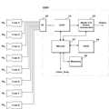
한편, 상기 감시용 디지털 비디오 레코더(DVR)에는, 도 1에 도시한 바와 같이, 인터페이스부(20), 디지털 신호 처리부(21), 멀티 채널 영상 생성부(22), 마이컴(23), 하드 디스크(24), 그리고 메모리(25) 등이 포함 구성되며, 상기 인터페이스부(20)를 통해 다수의 감시용 카메라들이 연결 접속될 수 있다.Meanwhile, as illustrated in FIG. 1, the monitoring digital video recorder (DVR) includes an
예를 들어, 도 1에 도시한 바와 같이, 제1 내지 제8 감시용 카메라들 (101∼108)이, 상기 인터페이스부(20)를 통해 연결 접속될 수 있는 데, 상기 디지털 신호 처리부(21)에서는, 제1 내지 제8 감시용 카메라(101∼108)에 의해 촬영되는 아날로그 영상신호가, 상기 인터페이스부(20)에 할당된 각 채널을 통해 수신되는 경우, 그 아날로그 영상신호를 디지털 영상신호로 신호 처리함과 아울러, MPEG 방식의 비디오 데이터로 변환하게 된다.For example, as shown in FIG. 1, the first to
그리고, 상기 마이컴(23)에서는, 상기 MPEG 방식으로 변환된 비디오 데이터를, 상기 하드 디스크(24)에 기록 저장시킴과 아울러, 사용자의 요청에 따라, 상기 멀티 채널 영상 생성부(22)를 동작 제어하여, 다수의 감시용 카메라들에 의해 촬영되는 각 채널별 영상신호들을, 멀티 채널 영상(Multi Channel Video)으로 화면 표시하게된다.In addition, the
예를 들어, 도 2에 도시한 바와 같이, 상기 멀티 채널 영상 생성부(22)에서는, 제1 내지 제4 감시용 카메라(101∼104)에 의해 촬영되는 제1 내지 제4 채널(CH1∼CH4)별 영상신호를 조합하여, 4 개의 분할 화면으로 표시하게 되는 데, 만일, 제2 채널과 제3 채널에 영상신호가 존재하지 않는 경우에는, 도 2에 도시한 바와 같이, 그에 해당하는 일부 영역에 무 신호(No-Signal) 화면이 표시된다.For example, as illustrated in FIG. 2, in the multi-channel
한편, 상기 마이컴(23)에서는, 사용자의 키 입력에 따라, 또는 소정 시간이 경과하는 경우, 상기 멀티 채널 영상 생성부(22)를 동작 제어하여, 도 2에 도시한 바와 같이, 제5 내지 제8 감시용 카메라(105∼108)에 의해 촬영되는 제5 내지 제8 채널(CH5∼CH8)별 영상신호를 4 개의 분할 화면으로 표시하게 되며, 만일, 제5 채 널과 제8 채널에 영상신호가 존재하지 않는 경우에는, 그에 해당하는 일부 영역에 무 신호(No-Signal) 화면이 표시된다.On the other hand, the
이에 따라, 사용자는, 다수의 감사용 카메라들에 의해 촬영되는 영상신호들을, N 개의 분할 화면으로 조합 표시되는 멀티 채널 영상을 통해 종합적으로 확인할 수 있게 된다.
Accordingly, the user can comprehensively check the video signals photographed by the plurality of audit cameras through the multi-channel video displayed by combining N divided screens.
그러나, 일반적인 감시용 디지털 비디오 레코더에서는, 상기와 같이 영상신호가 존재하지 않는 채널이, 멀티 채널 영상에 그대로 포함 표시되기 때문에, 영상신호가 출력되지 않는 채널을, 사용자가 불필요하게 확인하게 되며, 또한 도 2에 도시한 바와 같이, 영상신호가 존재하는 채널들만을 선별하여, 하나의 멀티 채널 영상에 모두 표시할 수 있음에도 불구하고, 복수의 멀티 채널 영상으로 나누어 표시하기 때문에, 사용상의 불편함과 감시 성능이 비효율적으로 저하되는 문제점이 있다.
However, in the general digital video recorder for monitoring, as described above, the channel without the video signal is displayed as it is included in the multi-channel video, so that the user unnecessarily confirms the channel where the video signal is not output. As shown in FIG. 2, although only channels having video signals are selected and displayed on one multi-channel video, they are divided into a plurality of multi-channel video and displayed. There is a problem that performance is inefficiently degraded.
따라서, 본 발명은 상기와 같은 문제점을 해결하기 위하여 창작된 것으로서, 여러 지역에 분산 설치된 다수의 감시용 카메라들과 연결 접속된 감시용 디지털 비디오 레코더(DVR)에서, 각 채널별 감시용 카메라의 영상 신호들을 조합하여, 멀티 채널 영상으로 표시하되, 무 신호 채널 스킵(No-Signal Channel Skip) 모드가 설정된 경우, 영상신호가 존재하지 않는 감시용 카메라의 채널을 자동으로 스킵하여, 영상 신호가 모두 존재하는 멀티 채널 영상을 화면 표시할 수 있도록 하기 위한 감시용 디지털 비디오 레코더에서의 멀티 채널 영상 표시장치 및 방법을 제공하는 데, 그 목적이 있는 것이다.
Therefore, the present invention was created to solve the above problems, in the surveillance digital video recorder (DVR) connected to a plurality of surveillance cameras distributed in various regions, the image of the surveillance camera for each channel Combining the signals and displaying them as multi-channel video, but when the No-Signal Channel Skip mode is set, all the video signals exist by automatically skipping the channel of the surveillance camera that does not exist. It is an object of the present invention to provide a multi-channel video display device and method in a digital video recorder for monitoring to display a multi-channel video.
상기와 같은 목적을 달성하기 위한 본 발명에 따른 감시용 디지털 비디오 레코더에서의 멀티 채널 영상 표시방법은, 다수의 감시용 카메라들에 의해 촬영되는 각 채널별 영상신호의 유무를 검출하는 1단계; 및 상기 영상신호가 검출되지 않는 채널을 자동으로 스킵(Skip)하여, 영상신호가 모두 존재하는 멀티 채널 영상을 화면 표시하는 2단계를 포함하여 이루어지는 것을 특징으로 하며,According to an aspect of the present invention, there is provided a multi-channel video display method for a digital video recorder for monitoring according to the present invention, the method comprising: detecting the presence or absence of a video signal for each channel photographed by a plurality of surveillance cameras; And automatically skipping a channel in which the video signal is not detected and displaying a multi-channel video in which all video signals exist.
또한, 본 발명에 따른 감시용 디지털 비디오 레코더에서의 멀티 채널 영상 표시장치는, 다수의 감시용 카메라들에 의해 촬영되는 각 채널별 영상신호의 유무를 검출하기 위한 검출수단; 상기 영상신호가 검출되지 않는 채널을 자동으로 스킵(Skip)하여, N 개의 멀티 채널 영상을 생성 출력하기 위한 생성수단; 및 상기 멀티 채널 영상 표시가 요청된 상태에서, 무 신호(No-Signal) 스킵 모드가 설정된 경우, 상기 생성수단을 동작 제어하여, 영상신호가 모두 존재하는 멀티 채널 영상이 화면 표시되도록 제어하기 위한 제어수단을 포함하여 구성되는 것을 특징으로 한다.
In addition, the multi-channel video display device in the surveillance digital video recorder according to the present invention, the detection means for detecting the presence or absence of a video signal for each channel photographed by a plurality of surveillance cameras; Generating means for automatically skipping a channel for which the video signal is not detected and generating and outputting N multi-channel images; And controlling to generate a multi-channel image in which all of the image signals exist by controlling the generation means when the no-signal skip mode is set in the state where the multi-channel image display is requested. It characterized in that it comprises a means.
이하, 본 발명에 따른 감시용 디지털 비디오 레코더에서의 멀티 채널 영상 표시장치 및 방법에 대한 바람직한 실시예에 대해, 첨부된 도면을 참조하여 상세히 설명한다.Hereinafter, exemplary embodiments of a multi-channel video display device and method in a digital video recorder for monitoring according to the present invention will be described in detail with reference to the accompanying drawings.
도 3은, 본 발명에 따른 감시용 디지털 비디오 레코더에서의 멀티 채널 영상 표시장치에 대한 구성을 도시한 것으로, 상기 감시용 디지털 비디오 레코더(DVR)에는, 인터페이스부(30), 디지털 신호 처리부(31), 멀티 채널 영상 생성부(32), 마이컴(33), 하드 디스크(34), 그리고 메모리(35) 등이 포함 구성됨과 아울러, 채널 신호 검출부(36)가 더 포함 구성된다.Fig. 3 shows a configuration of a multi-channel video display device in the surveillance digital video recorder according to the present invention. The surveillance digital video recorder (DVR) includes an
한편, 상기 인터페이스부(30)를 통해 다수의 감시용 카메라들이 연결 접속될 수 있는 데, 예를 들어, 도 3에 도시한 바와 같이, 제1 내지 제8 감시용 카메라들(101∼108)이, 상기 인터페이스부(30)를 통해 연결 접속되며, 상기 디지털 신호 처리부(31)에서는, 제1 내지 제8 감시용 카메라(101∼108)에 의해 촬영되는 아날로그 영상신호가, 상기 인터페이스부(30)에 할당된 각 채널들을 통해 수신되는 경우, 그 아날로그 영상신호를 디지털 영상신호로 신호 처리함과 아울러, MPEG 방식의 비디오 데이터로 변환하게 된다.Meanwhile, a plurality of surveillance cameras may be connected and connected through the
또한, 상기 마이컴(33)에서는, 상기 MPEG 방식으로 변환된 비디오 데이터를, 상기 하드 디스크(34)에 기록 저장시킴과 아울러, 사용자의 요청에 따라, 상기 멀티 채널 영상 생성부(32)를 동작 제어하여, 다수의 감시용 카메라들에 의해 촬영되는 각 채널별 영상신호들을, N 개의 분할 화면의 멀티 채널 영상(Multi Channel Video)으로 화면 표시하게 된다.In addition, the
한편, 상기 채널 신호 검출부(36)에서는, 상기 인터페이스부(30)를 통해 연결 접속된 제1 내지 제8 감시용 카메라(101∼108)로부터 영상신호가 정상적으로 출력되고 있는 지를 검출하게 되는 데, 예를 들어, 상기 채널 신호 검출부(36)에서는, 각 채널별 감시용 카메라로부터 동기(Sync) 신호가 출력되거나, 또는 출력 신호의 레벨(Level) 크기가, 사전에 설정된 기준 레벨 이상이 되는 경우, 해당하는 채널의 감시용 카메라로부터 영상신호가 정상적으로 출력되고 있다고 검출하게 된다.On the other hand, the channel
그리고, 상기 마이컴(33)에서는, 예를 들어 본 발명에서 새롭게 정의하는 '무 신호 채널 스킵 모드(No-Signal Channel Skip Mode)'를 설정하는 경우, 상기 채널 신호 검출부(36)에 의해 검출되는 무 신호 채널들을 확인한 후, 상기 멀티 채널 영상 생성부(32)를 동작 제어하여, 영상신호가 존재하지 않는 감시용 카메라의 채널을 자동으로 스킵함으로써, 영상신호가 모두 존재하는 멀티 채널 영상을 화면 표시하게 되는 데, 이에 대해 상세히 설명하면 다음과 같다.
In addition, in the
도 4는, 본 발명에 따른 감시용 디지털 비디오 레코더의 멀티 채널 영상 표시방법에 대한 동작 흐름도를 도시한 것으로, 전술한 바와 같이, 상기 감시용 디지털 비디오 레코더(DVR)에서는, 상기 인터페이스부(30)를 통해 연결 접속된 다수의 감시용 카메라들에 의해 촬영되는 영상신호를 수신하여, 모니터 등과 같은 외부 연결기기의 화면을 통해 표시하는 일련의 동작을 수행하게 된다(S10).4 is a flowchart illustrating a method for displaying a multi-channel video of a digital video recorder for monitoring according to the present invention. As described above, the
한편, 상기 마이컴(33)에서는, 사용자가 멀티 채널 영상을 표시할 것을 요청하는 경우(S11), 본 발명에서 새롭게 정의하는 '무 신호 채널 스킵 모드'가 설정되어 있는 지를 확인하게 되는 데(S12), 예를 들어 상기 무 신호 채널 스킵 모드가 설정되어 있지 않은 경우, 도 2를 참조로 전술한 바와 같이, 제1 내지 제4 감시용 카메라(101∼104)에 의해 촬영되는 제1 내지 제4 채널(CH1∼CH4)별 영상신호를 조합하여, 4 개의 분할 화면으로 표시하게 된다(S13).In the meantime, when the user requests to display a multi-channel image (S11), the
또한, 상기 마이컴(23)에서는, 사용자의 키 입력에 따라, 또는 소정 시간이 경과하는 경우(S14), 상기 멀티 채널 영상 생성부(32)를 동작 제어하여, 도 2를 참조로 전술한 바와 같이, 제5 내지 제8 감시용 카메라(105∼108)에 의해 촬영되는 제5 내지 제8 채널(CH5∼CH8)별 영상신호를 4 개의 분할 화면으로 표시하게 된다(S15).In addition, the
반면, 상기 마이컴(33)에서는, 상기 무 신호 채널 스킵 모드가 설정되어 있는 경우, 상기 채널 신호 검출부(36)를 동작 제어하여, 각 채널별 감시용 카메라로부터 영상신호가 정상적으로 출력되고 있는 지를 검출하게 되는 데(S16), 예를 들어 상기 채널 신호 검출부(36)에서는, 각 채널별 감시용 카메라로부터 동기(Sync) 신호가 출력되거나, 또는 출력 신호의 레벨(Level) 크기가, 사전에 설정된 기준 레벨 이상이 되는 경우, 해당하는 채널의 감시용 카메라로부터 영상신호가 정상적으로 출력되고 있다고 검출하게 된다.On the other hand, in the
또한, 상기 마이컴(33)에서는, 상기 채널 신호 검출부(36)에 의해 검출되는 무 신호 채널들을 확인한 후, 상기 멀티 채널 영상 생성부(32)를 동작 제어하여, 영상신호가 정상적으로 출력되는 채널만을 멀티 채널 영상으로 생성 및 화면 표시하게 되는 데(S17), 예를 들어, 도 5에 도시한 바와 같이, 제1 내지 제8 채널 중, 제1, 제4, 제6, 제7 채널에는 영상신호가 존재하고, 제2, 제3, 제5, 제8 채널을 통해서는 영상신호가 존재하지 않는 경우, 상기 멀티 채널 영상 생성부(32)에서는, 제1, 제4, 제6, 제7 채널만을 선별하여, 영상신호가 모두 존재하는 멀티 채널 영상을 화면 표시하게 된다.
In addition, the
이상, 전술한 본 발명의 바람직한 실시예는, 예시의 목적을 위해 개시된 것으로, 당업자라면, 이하 첨부된 특허청구범위에 개시된 본 발명의 기술적 사상과 그 기술적 범위 내에서, 또 다른 다양한 실시예들을 개량, 변경, 대체 또는 부가 등이 가능할 것이다.
As mentioned above, preferred embodiments of the present invention described above are disclosed for the purpose of illustration, and those skilled in the art can improve other various embodiments within the spirit and technical scope of the present invention disclosed in the appended claims below. Changes, substitutions or additions will be possible.
상기와 같이 구성 및 이루어지는 본 발명에 따른 감시용 디지털 비디오 레코더에서의 멀티 채널 영상 표시장치 및 방법은, 예를 들어 여러 지역에 분산 설치된 다수의 감시용 카메라들과 연결 접속된 감시용 디지털 비디오 레코더(DVR)에서, 각 채널별 감시용 카메라의 영상신호들을 조합하여, 멀티 채널 영상(Multi Channel Video)으로 표시하되, 무 신호 채널 스킵(No-Signal Channel Skip) 모드가 설정된 경우, 영상신호가 존재하지 않는 감시용 카메라의 채널을 자동으로 스킵하여, 영상 신호가 모두 존재하는 멀티 채널 영상을 화면 표시함으로써, 영상신호가 출력되지 않는 채널을, 사용자가 불필요하게 확인하지 않아도 되므로, 사용상의 편리성과 감시 성능을 보다 효율적으로 향상시킬 수 있게 되는 매우 유용한 발명인 것이다.The multi-channel video display device and method of the surveillance digital video recorder according to the present invention constructed and constructed as described above may include, for example, a surveillance digital video recorder connected to a plurality of surveillance cameras distributed in various regions. DVR) combines the video signals of surveillance cameras for each channel and displays them as multi-channel video, but when no-signal channel skip mode is set, no video signal exists. By automatically skipping the channel of the non-monitoring camera and displaying a multi-channel image in which all the video signals exist, the user does not need to check the channel where the video signal is not output unnecessarily. It is a very useful invention that can be improved more efficiently.
Claims (8)
Translated fromKoreanPriority Applications (1)
| Application Number | Priority Date | Filing Date | Title |
|---|---|---|---|
| KR1020040064621AKR20060016243A (en) | 2004-08-17 | 2004-08-17 | Multichannel Video Display Device and Method in Surveillance Digital Video Recorder |
Applications Claiming Priority (1)
| Application Number | Priority Date | Filing Date | Title |
|---|---|---|---|
| KR1020040064621AKR20060016243A (en) | 2004-08-17 | 2004-08-17 | Multichannel Video Display Device and Method in Surveillance Digital Video Recorder |
Publications (1)
| Publication Number | Publication Date |
|---|---|
| KR20060016243Atrue KR20060016243A (en) | 2006-02-22 |
Family
ID=37124564
Family Applications (1)
| Application Number | Title | Priority Date | Filing Date |
|---|---|---|---|
| KR1020040064621ACeasedKR20060016243A (en) | 2004-08-17 | 2004-08-17 | Multichannel Video Display Device and Method in Surveillance Digital Video Recorder |
Country Status (1)
| Country | Link |
|---|---|
| KR (1) | KR20060016243A (en) |
Cited By (9)
| Publication number | Priority date | Publication date | Assignee | Title |
|---|---|---|---|---|
| CN103618869A (en)* | 2013-11-25 | 2014-03-05 | 广东威创视讯科技股份有限公司 | Multi-image video stitching method and device |
| KR101650466B1 (en)* | 2016-03-25 | 2016-08-24 | 주식회사 대명코퍼레이션 | High definition video matrix controller |
| CN106878724A (en)* | 2011-06-28 | 2017-06-20 | 太阳专利托管公司 | Picture decoding method, method for encoding images, picture decoding apparatus, picture coding device and image encoding/decoding device |
| US10687074B2 (en) | 2011-06-27 | 2020-06-16 | Sun Patent Trust | Image decoding method, image coding method, image decoding apparatus, image coding apparatus, and image coding and decoding apparatus |
| US10903848B2 (en) | 2011-06-30 | 2021-01-26 | Sun Patent Trust | Image decoding method, image coding method, image decoding apparatus, image coding apparatus, and image coding and decoding apparatus |
| US11109043B2 (en) | 2011-06-24 | 2021-08-31 | Sun Patent Trust | Coding method and coding apparatus |
| USRE48810E1 (en) | 2011-06-23 | 2021-11-02 | Sun Patent Trust | Image decoding method and apparatus based on a signal type of the control parameter of the current block |
| US11343518B2 (en) | 2011-07-11 | 2022-05-24 | Sun Patent Trust | Image decoding method, image coding method, image decoding apparatus, image coding apparatus, and image coding and decoding apparatus |
| US11356666B2 (en) | 2011-06-30 | 2022-06-07 | Sun Patent Trust | Image decoding method, image coding method, image decoding apparatus, image coding apparatus, and image coding and decoding apparatus |
- 2004
- 2004-08-17KRKR1020040064621Apatent/KR20060016243A/ennot_activeCeased
Cited By (19)
| Publication number | Priority date | Publication date | Assignee | Title |
|---|---|---|---|---|
| USRE48810E1 (en) | 2011-06-23 | 2021-11-02 | Sun Patent Trust | Image decoding method and apparatus based on a signal type of the control parameter of the current block |
| USRE49906E1 (en) | 2011-06-23 | 2024-04-02 | Sun Patent Trust | Image decoding method and apparatus based on a signal type of the control parameter of the current block |
| US11758158B2 (en) | 2011-06-24 | 2023-09-12 | Sun Patent Trust | Coding method and coding apparatus |
| US11457225B2 (en) | 2011-06-24 | 2022-09-27 | Sun Patent Trust | Coding method and coding apparatus |
| US12231656B2 (en) | 2011-06-24 | 2025-02-18 | Sun Patent Trust | Coding method and coding apparatus |
| US11109043B2 (en) | 2011-06-24 | 2021-08-31 | Sun Patent Trust | Coding method and coding apparatus |
| US10687074B2 (en) | 2011-06-27 | 2020-06-16 | Sun Patent Trust | Image decoding method, image coding method, image decoding apparatus, image coding apparatus, and image coding and decoding apparatus |
| US10750184B2 (en) | 2011-06-28 | 2020-08-18 | Sun Patent Trust | Image decoding method, image coding method, image decoding apparatus, image coding apparatus, and image coding and decoding apparatus |
| CN106878724A (en)* | 2011-06-28 | 2017-06-20 | 太阳专利托管公司 | Picture decoding method, method for encoding images, picture decoding apparatus, picture coding device and image encoding/decoding device |
| US11356666B2 (en) | 2011-06-30 | 2022-06-07 | Sun Patent Trust | Image decoding method, image coding method, image decoding apparatus, image coding apparatus, and image coding and decoding apparatus |
| US10903848B2 (en) | 2011-06-30 | 2021-01-26 | Sun Patent Trust | Image decoding method, image coding method, image decoding apparatus, image coding apparatus, and image coding and decoding apparatus |
| US11792400B2 (en) | 2011-06-30 | 2023-10-17 | Sun Patent Trust | Image decoding method, image coding method, image decoding apparatus, image coding apparatus, and image coding and decoding apparatus |
| US12212753B2 (en) | 2011-06-30 | 2025-01-28 | Sun Patent Trust | Image decoding method, image coding method, image decoding apparatus, image coding apparatus, and image coding and decoding apparatus |
| US12108059B2 (en) | 2011-07-11 | 2024-10-01 | Sun Patent Trust | Image decoding method, image coding method, image decoding apparatus, image coding apparatus, and image coding and decoding apparatus |
| US11343518B2 (en) | 2011-07-11 | 2022-05-24 | Sun Patent Trust | Image decoding method, image coding method, image decoding apparatus, image coding apparatus, and image coding and decoding apparatus |
| US11770544B2 (en) | 2011-07-11 | 2023-09-26 | Sun Patent Trust | Image decoding method, image coding method, image decoding apparatus, image coding apparatus, and image coding and decoding apparatus |
| CN103618869A (en)* | 2013-11-25 | 2014-03-05 | 广东威创视讯科技股份有限公司 | Multi-image video stitching method and device |
| CN103618869B (en)* | 2013-11-25 | 2017-07-18 | 广东威创视讯科技股份有限公司 | Many picture video joining methods and device |
| KR101650466B1 (en)* | 2016-03-25 | 2016-08-24 | 주식회사 대명코퍼레이션 | High definition video matrix controller |
Similar Documents
| Publication | Publication Date | Title |
|---|---|---|
| KR100883066B1 (en) | Apparatus and method for displaying a moving path of a subject using text | |
| KR100200616B1 (en) | Display device for watching-screen dividing and method therefor | |
| US20070159529A1 (en) | Method and apparatus for controlling output of a surveillance image | |
| JP6415061B2 (en) | Display control apparatus, control method, and program | |
| KR101082027B1 (en) | Apparatus for control and observing event | |
| KR20060016243A (en) | Multichannel Video Display Device and Method in Surveillance Digital Video Recorder | |
| KR100627585B1 (en) | Video monitoring device and its display method | |
| KR101311463B1 (en) | remote video transmission system | |
| JP2019029888A (en) | Imaging apparatus, information processing method, and program | |
| US20090219453A1 (en) | Video display apparatus | |
| JP2003009142A (en) | Monitoring systems and controls | |
| KR100930338B1 (en) | Channel Information Display Method in Surveillance Digital Video Recorder | |
| KR101198159B1 (en) | Method for controlling record each motion detection area | |
| KR101198172B1 (en) | Apparatus and method for displaying a reference image and a surveilliance image in digital video recorder | |
| KR20150026355A (en) | Apparatus and method for backup image | |
| KR101531190B1 (en) | Digital video recorder and channel mapping method | |
| JP3129692B2 (en) | Frame converter | |
| KR100536699B1 (en) | Method for selecting audio signal in a timelapse vcr | |
| KR100188440B1 (en) | Multi-split screen display method and system suitable for surveillance camera system | |
| KR20020043832A (en) | Methods and Apparatuses for Monitoring System using Multi-Channel/Multi-Level Motion Detector | |
| JPH08287367A (en) | Camera monitoring device | |
| KR20080022837A (en) | Camera video recording method in digital video recorder | |
| KR20090069526A (en) | Semi-sequential channel display device and method in digital video recorder | |
| JPH0767098A (en) | Video surveillance | |
| KR100482838B1 (en) | Method for setting control data in digital video recorder for monitoring |
Legal Events
| Date | Code | Title | Description |
|---|---|---|---|
| PA0109 | Patent application | Patent event code:PA01091R01D Comment text:Patent Application Patent event date:20040817 | |
| PG1501 | Laying open of application | ||
| A201 | Request for examination | ||
| PA0201 | Request for examination | Patent event code:PA02012R01D Patent event date:20090812 Comment text:Request for Examination of Application Patent event code:PA02011R01I Patent event date:20040817 Comment text:Patent Application | |
| E902 | Notification of reason for refusal | ||
| PE0902 | Notice of grounds for rejection | Comment text:Notification of reason for refusal Patent event date:20101123 Patent event code:PE09021S01D | |
| E601 | Decision to refuse application | ||
| PE0601 | Decision on rejection of patent | Patent event date:20110421 Comment text:Decision to Refuse Application Patent event code:PE06012S01D Patent event date:20101123 Comment text:Notification of reason for refusal Patent event code:PE06011S01I |