KR20060013894A - Optical pickup including liquid crystal element for aberration correction - Google Patents
Optical pickup including liquid crystal element for aberration correctionDownload PDFInfo
- Publication number
- KR20060013894A KR20060013894AKR1020040062513AKR20040062513AKR20060013894AKR 20060013894 AKR20060013894 AKR 20060013894AKR 1020040062513 AKR1020040062513 AKR 1020040062513AKR 20040062513 AKR20040062513 AKR 20040062513AKR 20060013894 AKR20060013894 AKR 20060013894A
- Authority
- KR
- South Korea
- Prior art keywords
- liquid crystal
- light
- optical pickup
- light source
- crystal element
- Prior art date
- Legal status (The legal status is an assumption and is not a legal conclusion. Google has not performed a legal analysis and makes no representation as to the accuracy of the status listed.)
- Withdrawn
Links
Images


Classifications
- G—PHYSICS
- G11—INFORMATION STORAGE
- G11B—INFORMATION STORAGE BASED ON RELATIVE MOVEMENT BETWEEN RECORD CARRIER AND TRANSDUCER
- G11B7/00—Recording or reproducing by optical means, e.g. recording using a thermal beam of optical radiation by modifying optical properties or the physical structure, reproducing using an optical beam at lower power by sensing optical properties; Record carriers therefor
- G11B7/12—Heads, e.g. forming of the optical beam spot or modulation of the optical beam
- G11B7/135—Means for guiding the beam from the source to the record carrier or from the record carrier to the detector
- G11B7/1365—Separate or integrated refractive elements, e.g. wave plates
- G11B7/1369—Active plates, e.g. liquid crystal panels or electrostrictive elements
- G—PHYSICS
- G02—OPTICS
- G02F—OPTICAL DEVICES OR ARRANGEMENTS FOR THE CONTROL OF LIGHT BY MODIFICATION OF THE OPTICAL PROPERTIES OF THE MEDIA OF THE ELEMENTS INVOLVED THEREIN; NON-LINEAR OPTICS; FREQUENCY-CHANGING OF LIGHT; OPTICAL LOGIC ELEMENTS; OPTICAL ANALOGUE/DIGITAL CONVERTERS
- G02F1/00—Devices or arrangements for the control of the intensity, colour, phase, polarisation or direction of light arriving from an independent light source, e.g. switching, gating or modulating; Non-linear optics
- G02F1/01—Devices or arrangements for the control of the intensity, colour, phase, polarisation or direction of light arriving from an independent light source, e.g. switching, gating or modulating; Non-linear optics for the control of the intensity, phase, polarisation or colour
- G02F1/13—Devices or arrangements for the control of the intensity, colour, phase, polarisation or direction of light arriving from an independent light source, e.g. switching, gating or modulating; Non-linear optics for the control of the intensity, phase, polarisation or colour based on liquid crystals, e.g. single liquid crystal display cells
- G02F1/137—Devices or arrangements for the control of the intensity, colour, phase, polarisation or direction of light arriving from an independent light source, e.g. switching, gating or modulating; Non-linear optics for the control of the intensity, phase, polarisation or colour based on liquid crystals, e.g. single liquid crystal display cells characterised by the electro-optical or magneto-optical effect, e.g. field-induced phase transition, orientation effect, guest-host interaction or dynamic scattering
- G02F1/13718—Devices or arrangements for the control of the intensity, colour, phase, polarisation or direction of light arriving from an independent light source, e.g. switching, gating or modulating; Non-linear optics for the control of the intensity, phase, polarisation or colour based on liquid crystals, e.g. single liquid crystal display cells characterised by the electro-optical or magneto-optical effect, e.g. field-induced phase transition, orientation effect, guest-host interaction or dynamic scattering based on a change of the texture state of a cholesteric liquid crystal
- G—PHYSICS
- G11—INFORMATION STORAGE
- G11B—INFORMATION STORAGE BASED ON RELATIVE MOVEMENT BETWEEN RECORD CARRIER AND TRANSDUCER
- G11B7/00—Recording or reproducing by optical means, e.g. recording using a thermal beam of optical radiation by modifying optical properties or the physical structure, reproducing using an optical beam at lower power by sensing optical properties; Record carriers therefor
- G11B7/12—Heads, e.g. forming of the optical beam spot or modulation of the optical beam
- G11B7/13—Optical detectors therefor
- G—PHYSICS
- G11—INFORMATION STORAGE
- G11B—INFORMATION STORAGE BASED ON RELATIVE MOVEMENT BETWEEN RECORD CARRIER AND TRANSDUCER
- G11B7/00—Recording or reproducing by optical means, e.g. recording using a thermal beam of optical radiation by modifying optical properties or the physical structure, reproducing using an optical beam at lower power by sensing optical properties; Record carriers therefor
- G11B7/12—Heads, e.g. forming of the optical beam spot or modulation of the optical beam
- G11B7/135—Means for guiding the beam from the source to the record carrier or from the record carrier to the detector
- G11B7/1372—Lenses
- G11B7/1374—Objective lenses
- G—PHYSICS
- G11—INFORMATION STORAGE
- G11B—INFORMATION STORAGE BASED ON RELATIVE MOVEMENT BETWEEN RECORD CARRIER AND TRANSDUCER
- G11B7/00—Recording or reproducing by optical means, e.g. recording using a thermal beam of optical radiation by modifying optical properties or the physical structure, reproducing using an optical beam at lower power by sensing optical properties; Record carriers therefor
- G11B7/12—Heads, e.g. forming of the optical beam spot or modulation of the optical beam
- G11B7/135—Means for guiding the beam from the source to the record carrier or from the record carrier to the detector
- G11B7/1372—Lenses
- G11B7/1378—Separate aberration correction lenses; Cylindrical lenses to generate astigmatism; Beam expanders
- G—PHYSICS
- G11—INFORMATION STORAGE
- G11B—INFORMATION STORAGE BASED ON RELATIVE MOVEMENT BETWEEN RECORD CARRIER AND TRANSDUCER
- G11B7/00—Recording or reproducing by optical means, e.g. recording using a thermal beam of optical radiation by modifying optical properties or the physical structure, reproducing using an optical beam at lower power by sensing optical properties; Record carriers therefor
- G11B7/12—Heads, e.g. forming of the optical beam spot or modulation of the optical beam
- G11B7/135—Means for guiding the beam from the source to the record carrier or from the record carrier to the detector
- G11B7/1395—Beam splitters or combiners
Landscapes
- Physics & Mathematics (AREA)
- Optics & Photonics (AREA)
- Chemical & Material Sciences (AREA)
- Crystallography & Structural Chemistry (AREA)
- Nonlinear Science (AREA)
- General Physics & Mathematics (AREA)
- Optical Head (AREA)
Abstract
Translated fromKoreanDescription
Translated fromKorean도 1은 본 발명에 따른 수차 보정용 액정소자를 구비한 광픽업의 광학적 구성의 일 실시예를 개략적으로 보여준다.1 schematically shows an embodiment of an optical configuration of an optical pickup having a liquid crystal element for aberration correction according to the present invention.
도 2는 도 1의 수차 보정용 액정소자의 배치도이다.FIG. 2 is a layout view of the aberration correction liquid crystal device of FIG. 1.
도 3은 본 발명에 따른 수차 보정용 액정소자의 구조를 개략적으로 보여준다.3 schematically shows the structure of an aberration correction liquid crystal device according to the present invention.
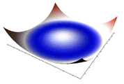
도 4 및 도 5는 상기와 같은 액정소자에 전기장 인가시의 위상차 분포를 컴퓨터 시뮬레이션하여 얻은 결과를 보여주는 것으로, 도 4는 위상차 분포를 2차원적으로 나타낸 결과이며, 도 5는 위상차 분포를 3차원 플롯(plot)한 결과이다.4 and 5 show the results obtained by computer simulation of the phase difference distribution when the electric field is applied to the liquid crystal device as described above. FIG. 4 shows the two-dimensional phase difference distribution, and FIG. 5 shows the three-dimensional phase difference distribution. This is the result of the plot.
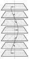
도 6은 일정한 주기로 회전하는 분자 배열 상태를 가지는 액정의 광의 진행 방향을 축으로 회전하는 구조의 배향 상태를 보여준다.FIG. 6 shows an alignment state of a structure in which the light propagation direction of a liquid crystal having a molecular arrangement state rotating at a constant cycle is rotated about an axis.
도 7은 본 발명에 따른 광픽업을 채용한 광 기록 및/또는 재생기기의 구성을 개략적으로 보인 도면이다.7 is a diagram schematically showing the configuration of an optical recording and / or reproducing apparatus employing an optical pickup according to the present invention.
<도면의 주요부분에 대한 부호의 설명><Description of the symbols for the main parts of the drawings>
1...광디스크 10...광원1 ...
14...편광빔스프리터 19...파장판14 ... polarizing
20...액정소자 21,29...제1 및 제2기판20 ...
25...액정층 30...대물렌즈25 ...
40...광검출기40.Photodetector
본 발명은 광픽업에 관한 것으로, 보다 상세하게는 수차 보정용 액정 소자를 구비한 광픽업에 관한 것이다.The present invention relates to an optical pickup, and more particularly, to an optical pickup having a liquid crystal element for aberration correction.
레이저광을 대물렌즈에 의해 집속한 집광스폿을 이용하여 광정보저장매체인 광디스크에 임의의 정보를 기록하거나 기록된 정보를 재생하는 광 기록 및/또는 재생기기에서, 기록 용량은 집광되는 스폿의 크기에 의해 정해진다. 집광스폿의 크기(S)는 사용하는 레이저광 파장(λ)와 대물렌즈의 개구수(NA: Numerical Aperture)에 의해 수학식 1과 같이 결정된다.In an optical recording and / or reproducing apparatus for recording arbitrary information or reproducing recorded information by using a condensing spot focusing a laser beam by an objective lens, the recording capacity is the size of the spot to be condensed. Determined by The size S of the condensed spot is determined as shown in

따라서, 광디스크의 고밀도화를 위해 광디스크에 맺히는 광스폿의 크기를 줄이기 위해서는, 청색레이저와 같은 단파장 광원과 개구수 0.6 이상의 대물렌즈 채용이 필수적이다.Therefore, in order to reduce the size of the optical spot formed on the optical disk for the higher density of the optical disk, it is essential to employ a short wavelength light source such as a blue laser and an objective lens having a numerical aperture of 0.6 or more.
780nm 파장의 광과 개구수 0.45 또는 0.5인 대물렌즈를 이용하여 정보의 기록 및/또는 재생이 이루어지도록 된 CD가 나온 이래로, 기록 밀도를 높여 정보 저장 용량을 늘리기 위한 많은 연구가 이루어져 왔다. 그 결과물이 650 nm 파장의 광과 개구수 0.6 또는 0.65인 대물렌즈를 이용하여 정보의 기록 및/또는 재생이 이루 어지도록 된 DVD이다.Since CDs have been developed to record and / or reproduce information using light of 780 nm wavelength and objective lenses having a numerical aperture of 0.45 or 0.5, many studies have been made to increase information storage capacity by increasing recording density. The result is a DVD that allows recording and / or reproducing of information using light of 650 nm wavelength and an objective lens having a numerical aperture of 0.6 or 0.65.
현재는 청자색 파장 예컨대, 405nm 파장의 광을 이용하여 20GB 이상의 기록용량을 가질 수 있도록 된 고밀도 광디스크에 대한 연구가 꾸준히 진행되고 있다.At present, research on a high-density optical disk that can have a recording capacity of 20GB or more by using light of a blue violet wavelength, for example, a wavelength of 405nm has been continuously conducted.
고밀도 광디스크는 현재 규격화가 활발히 진행되고 있고 일부 규격은 거의 완료 단계에 있으며, 청자색 파장 예컨대, 405nm 파장의 광을 이용한다. 이때, 고밀도 광디스크를 위한 대물렌즈의 개구수는 후술하는 바와 같이 0.65 또는 0.85이다.High-density optical discs are currently being actively standardized and some standards are nearing completion and use light of blue violet wavelengths, such as 405 nm wavelength. At this time, the numerical aperture of the objective lens for the high density optical disc is 0.65 or 0.85 as will be described later.
CD는 두께가 1.2mm인데, DVD의 경우에 두께를 0.6mm로 줄인 이유는 개구수가 CD의 경우 0.45에서 DVD의 경우 0.6 정도로 높아졌기 때문에, 광디스크의 틸트에 의한 공차를 확보하기 위해서이다.Although the CD has a thickness of 1.2 mm, the reason for reducing the thickness to 0.6 mm in the case of DVD is to secure the tolerance due to the tilt of the optical disc since the numerical aperture has increased from 0.45 in the case of CD to 0.6 in the case of DVD.
광디스크의 틸트에 의한 공차를 확보하기 위해서는, 고밀도화를 위해 대물렌즈의 개구수를 높일 경우에는 광디스크의 두께를 줄일 필요가 있다. CD의 경우 1.2mm에서 DVD의 경우 0.6mm로 줄였다.In order to secure the tolerance due to the tilt of the optical disk, it is necessary to reduce the thickness of the optical disk when the numerical aperture of the objective lens is increased for higher density. Reduced from 1.2mm for CD to 0.6mm for DVD.
또한, DVD보다 고용량을 가지는 고밀도 광디스크의 경우, 그 고밀도 광디스크를 위한 대물렌즈의 개구수를 예컨대, 0.85로 높인다면, 그 고밀도 광디스크의 두께는 대략 0.1mm 정도로 줄여야 한다. 이와 같이, 대물렌즈의 개구수를 높이고 그 광디스크의 두께를 얇게 한 것이 Blu-ray Disc(이하, BD)이다. BD 규격에서 광원의 파장은 405nm이고, 대물렌즈의 개구수는 0.85이며, 그 광디스크의 두께는 대략 0.1mm이다.Further, in the case of a high density optical disc having a higher capacity than a DVD, if the numerical aperture of the objective lens for the high density optical disc is increased to, for example, 0.85, the thickness of the high density optical disc should be reduced to about 0.1 mm. In this way, the numerical aperture of the objective lens is increased and the thickness of the optical disc is reduced. In the BD standard, the wavelength of the light source is 405 nm, the numerical aperture of the objective lens is 0.85, and the thickness of the optical disk is approximately 0.1 mm.
고밀도 광디스크는 그 저장용량을 보다 증대하기 위해, DVD의 경우와 마찬가지로 복수의 기록층 구조로 형성할 필요가 있다.In order to further increase the storage capacity of the high density optical disc, it is necessary to form a plurality of recording layer structures as in the case of DVD.
편면에 2층 또는 그 이상의 기록층을 가지는 복수 기록층 광디스크는 단일 기록층을 가지는 경우에 비해 그 기록용량을 크게 늘릴 수 있다.Multiple recording layer optical discs having two or more recording layers on one side can greatly increase the recording capacity thereof compared with the case of having a single recording layer.
여기서, 광디스크는 한 편면에 대해 기록층의 개수가 몇 개냐에 따라, 단일 기록층을 가지는 단일층 광디스크(single layer optical disc)와, 복수 기록층을 가지는 복수층 광디스크(multi-layer optical disc)로 분류할 수 있다. 또한, 광디스크는 기록층이 한 편면에만 있는 한면 구조와, 기록층이 양 편면에 각각 형성되어 있는 양면 구조로 분류할 수 있다.Here, the optical disc is a single layer optical disc having a single recording layer and a multi-layer optical disc having a plurality of recording layers, depending on the number of recording layers on one side. Can be classified. Further, optical discs can be classified into a single-sided structure in which the recording layer is only on one side, and a double-sided structure in which the recording layer is formed on both sides.
한 편면에 대해 2개의 기록층을 가지는 광디스크를 이층 광디스크(dual layer optical disc)라 한다. 이 이층 광디스크에는 다시 한면 구조의 이층 광디스크와 양면 구조의 이층 광디스크가 있다.An optical disc having two recording layers on one side is called a dual layer optical disc. The two-layer optical disc further includes a two-layer optical disc having a single side structure and a double-layer optical disc having a double side structure.
상기와 같이 편면에 복수 기록층을 가지는 구조로 광디스크를 형성하면, 기록용량을 크게 늘릴 수 있다. 하지만, 기록층 사이의 간격 차이에 기인한 구면수차 문제가 발생할 수 있다.If the optical disc is formed with a structure having a plurality of recording layers on one side as described above, the recording capacity can be greatly increased. However, spherical aberration problems may occur due to the difference in gap between recording layers.
예를 들어, 2층 고밀도 광디스크를 광픽업으로 기록 및/또는 재생하고자 할 경우에는, 대물렌즈는 두 기록층 중 어느 한 기록층에 대해 최적화되거나, 두 기록층 사이의 중간 정도에 최적화된다.For example, when recording and / or reproducing a two-layer high density optical disc by optical pickup, the objective lens is optimized for either one of the two recording layers, or about halfway between the two recording layers.
따라서, 대물렌즈가 두 기록층 중 어느 한 기록층에 대해 최적화된 경우에는 다른 기록층을 기록 및/또는 재생시에 구면수차가 발생하게 되며, 대물렌즈가 두 기록층 사이의 중간 정도에 최적화된 경우에는 두 기록층 모두의 기록 및/또는 재생시에 구면수차가 발생하게 된다.Therefore, when the objective lens is optimized for one of the two recording layers, spherical aberration occurs when recording and / or reproducing the other recording layer, and the objective lens is optimized about halfway between the two recording layers. Spherical aberration occurs during recording and / or reproduction of both recording layers.
따라서, 대략 0.1mm의 보호층 두께를 가지는 디스크 및 0.85의 고 개구수를 가지는 대물렌즈를 적용하는 고밀도 광디스크 시스템에서, 보호층 두께가 기준치에서 벗어난 경우에 발생하는 구면 수차를 보정하기 위한 수차보정소자가 필요하며, 이러한 수차보정소자로 주로 액정 패널을 사용한다.Therefore, in a high-density optical disk system employing a disk having a protective layer thickness of approximately 0.1 mm and an objective lens having a high numerical aperture of 0.85, aberration correcting elements for correcting spherical aberration occurring when the protective layer thickness deviates from the reference value. The liquid crystal panel is mainly used as the aberration correction element.
종래의 수차 보정용 액정 패널은 주로 전기장 인가 전에 기판과 액정 분자가 평행하게 배열되는 균질(homogeneous) 방식으로 형성되는 것으로, 수차의 분포에 대응하도록 전극이 패터닝된다. 이러한 종래의 수차 보정용 액정 패널에 전기장을 인가하여 수차와 반대 부호의 위상차를 발생시키는 방법을 통해 구면수차의 보정이 이루어진다. A conventional liquid crystal panel for aberration correction is formed in a homogeneous manner in which a substrate and liquid crystal molecules are arranged in parallel before application of an electric field, and an electrode is patterned to correspond to the distribution of aberration. The spherical aberration is corrected by applying an electric field to the conventional liquid crystal panel for correcting aberration to generate a phase difference opposite to the aberration.
따라서, 이러한 액정 패널을 사용하면, 편면에 복수 기록층을 가지는 구조의 광디스크 기록 및/또는 재생시, 기록층 사이의 간격 차이에 기인한 구면수차 문제가 해결될 수 있을 것이다.Therefore, by using such a liquid crystal panel, the problem of spherical aberration due to the difference in gap between recording layers in recording and / or reproducing an optical disc of a structure having a plurality of recording layers on one side may be solved.
종래의 액정 패널이 광원에서 출사되고 편광빔스프리터를 경유하여 입사되는 일 선편광 예컨대, P 편광의 광에 대해서는 기록층을 기록 및/또는 재생할 때 발생하는 구면수차를 보정하도록 동작된다고 할 때, 이러한 구면수차의 보정은 기록층을 기록 및/또는 재생할 때 발생하는 구면수차와 반대되는 방향으로 위상차를 발생시킴에 의해 행해진다.A conventional liquid crystal panel is operated to correct spherical aberration which occurs when recording and / or reproducing a recording layer with respect to one linearly polarized light emitted from a light source and incident through a polarizing beam splitter, for example, P polarized light. Correction of aberration is performed by generating a phase difference in a direction opposite to spherical aberration generated when recording and / or reproducing a recording layer.
그런데, 종래의 액정 패널을 사용하는 경우에는, 액정 패널, 1/4 파장판, 대물렌즈 순서로 배치되므로, 광디스크에서 반사되고 1/4 파장판을 투과한 광은, S 편광으로 되어 액정 패널을 그대로 투과하게 된다.By the way, when using a conventional liquid crystal panel, since it arranges in order of a liquid crystal panel, a quarter wave plate, and an objective lens, the light reflected by an optical disk and transmitted through the quarter wave plate becomes S polarized light, It is transmitted as it is.
즉, 액정 패널을 통과한 P 선편광의 광이 1/4 파장판을 경유하면서 일 원편광 예컨대, 우원편광의 광으로 바뀌어 광디스크쪽으로 진행한다고 하자. 이 경우, 일 원편광의 광은 광디스크(1)에서 반사되면서 다른 원편광 예컨대, 좌원 편광의 광으로 되고, 1/4 파장판을 다시 경유하면서 다른 직선편광 예컨대, S 선편광의 광으로 되어, 액정 패널을 그대로 투과하게 된다.In other words, it is assumed that the light of P linearly polarized light that has passed through the liquid crystal panel is converted into one circularly polarized light, for example, right circularly polarized light, and passes through the quarter wave plate and proceeds toward the optical disk. In this case, the light of one circularly polarized light is reflected by the
따라서, 광디스크에서 반사되어 액정 패널로 재 입사되는 광에 포함되어 있는 원래의 구면수차 보정을 위해 발생시킨 위상차는 액정 패널에 의해 보정되지 못하게 된다. 이에 의해, 정보 재생신호 및/또는 오차신호 검출을 위해 광검출기에 수광되는 광에는 구면수차 보정을 위해 발생시킨 위상차에 기인한 수차 즉, 구면수차가 잔존하게 된다.Therefore, the phase difference generated for the correction of the original spherical aberration included in the light reflected from the optical disk and re-incident to the liquid crystal panel cannot be corrected by the liquid crystal panel. As a result, aberration, i.e., spherical aberration due to the phase difference generated for spherical aberration correction, remains in the light received by the photodetector for detecting the information reproduction signal and / or the error signal.
이러한 구면수차가 잔존하면, 포커스 옵셋(Focus offset)이 크게 발생되어, 복수층 광디스크에서의 층 점프(layer jump)시 재생 및/또는 기록 특성이 나빠지며, 서보 조정을 위한 마진이 줄어들게 되는 문제점이 있다. 또한, DVD-RAM과 같은 랜드/그루브 구조의 광디스크의 경우에는 포커스 크로스 토크(Focus Cross-talk)가 크게 발생하여, 통상적으로 포커스 에러신호 검출에 사용하는 비점수차법을 사용하기 어려운 문제가 생긴다.If such spherical aberrations remain, a large focus offset is generated, resulting in poor reproduction and / or recording characteristics during layer jumps on a multi-layer optical disc, and a decrease in margin for servo adjustment. have. In addition, in case of an optical disc having a land / groove structure such as a DVD-RAM, focus cross-talk is largely generated, which makes it difficult to use an astigmatism method that is typically used for detecting a focus error signal.
이와 같이, 종래의 수차보정용 액정 패널은 편광 의존성을 가져, 서로 직교하는 광디스크로 입사하는 광과 광검출기로 회귀하는 광 모두에 대한 수차 보정효과를 볼 수 없어, 문제가 발생하게 된다.As described above, the conventional liquid crystal panel for aberration correction has polarization dependency, and thus aberration correction effects for both light incident on the optical disks orthogonal to each other and light returning to the photodetector cannot be seen, resulting in problems.
이를 보완하기 위해, 종래에는 상기 입사광의 편광 방향과 일치하는 액정 디렉터(director)를 갖는 액정 셀과, 회귀광의 편광 방향과 일치하는 액정 디렉터 분포를 갖는 액정 셀을 병행하여 사용하는 기술이 제안된 바 있다. 그러나, 이는 두 개의 액정셀을 사용해야 하므로, 제조 공정 복잡화, 투과율 감소, 비용 증가 및 이 를 적용한 광픽업의 크기 증가를 초래한다.In order to compensate for this, in the related art, a technique of using a liquid crystal cell having a liquid crystal director coincident with the polarization direction of the incident light and a liquid crystal cell having a liquid crystal director distribution coincident with the polarization direction of the returned light has been proposed. have. However, this requires the use of two liquid crystal cells, which leads to complicated manufacturing process, reduced transmittance, increased cost, and increased size of optical pickup.
또한, 종래에는 광디스크로 입사하는 광을 타원 편광으로 하여, 회귀 광이 두가지 편광 성분을 모두 갖도록 하여, 회귀 광도 액정 패널에 의한 수차 보정효과를 볼 수 있는 하는 기술이 제안된 바 있다. 그러나, 이는 추가적인 홀로그램소자를 필요로 하므로, 상기한 두 개의 액정 셀을 사용하는 경우와 마찬가지로, 제조 공정 복잡화, 투과율 감소, 비용 증가 및 광픽업의 크기 증가를 초래한다.In addition, conventionally, a technique has been proposed in which the light incident on the optical disk is elliptically polarized, and the regressed light has both polarization components, so that the aberration correction effect by the regression light liquid crystal panel can be seen. However, since this requires an additional hologram element, as in the case of using the two liquid crystal cells described above, it leads to complicated manufacturing process, reduced transmittance, increased cost, and increased size of optical pickup.
또한, 상기한 바와 같이, 수차 보정을 위해 전극을 패터닝한 구조로 액정 패널을 형성한 경우에는, 각 분할 전극을 구동하는 배선 및 구동 회로를 필요로 하므로, 배선 및 구동이 복잡한 문제가 있다.In addition, as described above, when the liquid crystal panel is formed in a structure in which electrodes are patterned for aberration correction, wiring and driving circuits for driving the respective divided electrodes are required, so that wiring and driving are complicated.
본 발명은 상기한 바와 같은 점을 감안하여 안출된 것으로, 전극 패터닝의 필요성을 없애고, 하나의 패널만으로도 편광 의존성을 극복하여 왕복하는 광 모두에 대해 수차 보정 효과를 줄 수 있도록 된 수차보정용 액정소자를 구비한 광픽업을 제공하는데 그 목적이 있다.The present invention has been made in view of the above-mentioned point, and eliminates the necessity of electrode patterning, overcomes polarization dependence with only one panel, and provides an aberration correction liquid crystal device for aberration correction effect for both reciprocating light. An object of the present invention is to provide an optical pickup.
상기 목적을 달성하기 위한 본 발명에 따른 광픽업은, 광원과; 상기 광원에서 출사된 광을 집속시켜 기록매체에 광스폿으로 맺히도록 하는 대물렌즈와; 상기 기록매체에서 반사된 광을 수광하여 정보 신호 및/또는 오차신호를 검출하기 위한 광검출기와; 수차를 보정하기 위한 액정소자와; 상기 광원쪽에서 입사되는 광의 편광을 변화시키는 파장판;을 포함하며, 상기 액정소자는, 상기 수차에 대응하는 도우넛 형의 그레디언트 두께 프로필을 갖는 기판을 구비하는 것을 특징으로 한다.Optical pickup according to the present invention for achieving the above object, the light source; An objective lens for condensing the light emitted from the light source to form a light spot on the recording medium; A photodetector for receiving information reflected from the recording medium to detect an information signal and / or an error signal; A liquid crystal element for correcting aberrations; And a wave plate for varying the polarization of the light incident from the light source, wherein the liquid crystal device has a substrate having a donut-shaped gradient thickness profile corresponding to the aberration.
상기 액정소자는, 제1 및 제2기판과, 상기 제1 및 제2기판 사이에 채워진 액정층을 포함하며, 상기 제1 및 제2기판 중 적어도 어느 하나는 그 내측면에 상기 도우넛 형의 그레디언트 두께 프로필을 가지도록 높낮이 분포가 형성되어 있으며, 상기 액정층은, 일정한 주기로 회전하는 분자 배열 상태를 가지는 액정으로 이루어질 수 있다.The liquid crystal device includes first and second substrates and a liquid crystal layer filled between the first and second substrates, and at least one of the first and second substrates has a donut-shaped gradient on an inner surface thereof. The height distribution is formed to have a thickness profile, and the liquid crystal layer may be formed of a liquid crystal having a molecular arrangement that rotates at a constant cycle.
여기서, 상기 도우넛 형의 그레디언트 두께 프로필은 상기 광원에서 출사되어 기록매체쪽으로 진행하는 광에 대해 기록매체의 두께 차이에 의한 구면수차와 동일한 높낮이 분포을 가지며, 상기 제1 및 제2기판 사이의 셀 갭은 상기 구면수차와 일치하는 분포를 가질 수 있다.Here, the donut-shaped gradient thickness profile has a height distribution equal to the spherical aberration due to the thickness difference of the recording medium with respect to the light emitted from the light source and traveling toward the recording medium, and the cell gap between the first and second substrates is It may have a distribution that matches the spherical aberration.
상기 액정층은, 콜레스테릭 액정 즉, 카이랄 네마틱 액정으로 이루어질 수 있다.The liquid crystal layer may be made of cholesteric liquid crystal, that is, chiral nematic liquid crystal.
상기 기판은, 청색파장영역에 대해 상기 액정층의 액정의 정상 굴절율과 동일 또는 인덱스 매칭이 가능한 유사한 굴절율을 가지는 글래스 재료로 이루어진 것이 바람직하다.The substrate is preferably made of a glass material having a similar refractive index that is equal to or equal to the normal refractive index of the liquid crystal of the liquid crystal layer with respect to the blue wavelength region.
상기 파장판은 상기 광원에서 출사된 광의 파장에 대해 1/4 파장판을 구비하여, 상기 액정소자로 입사되는 유효 광이 원편광이 되도록 된 것이 바람직하다.The wave plate preferably has a quarter wave plate with respect to the wavelength of the light emitted from the light source, so that the effective light incident on the liquid crystal element becomes circularly polarized light.
여기서, 상기 광원과 파장판 사이에 편광 의존성 광로 변환기;를 더 포함할 수 있다.Here, the polarization-dependent optical path converter between the light source and the wave plate; may further include.
이하, 첨부된 도면들을 참조하면서, 본 발명에 따른 수차 보정용 액정소자 및 이를 구비한 광픽업의 바람직한 실시예를 상세히 설명한다.Hereinafter, with reference to the accompanying drawings, it will be described in detail a preferred embodiment of the liquid crystal device for aberration correction and the optical pickup having the same according to the present invention.
이하의 상세한 설명 및 청구범위에서, 광디스크의 두께(기록매체의 두께)는, 광디스크의 기록 및/또는 재생광이 입사되는 표면 즉, 광입사면으로부터 대상 기록층까지의 두께를 말하며, 광디스크의 두께 차이(기록매체의 두께 차이)는 대물렌즈 설계치와의 차이를 말한다.In the following detailed description and claims, the thickness (thickness of the recording medium) of the optical disc refers to the surface from which the recording and / or reproducing light of the optical disc is incident, that is, the thickness from the light incident surface to the target recording layer, and the thickness of the optical disc. The difference (difference in thickness of the recording medium) refers to the difference from the objective lens design value.
편면에 2층의 기록층을 가지는 2층 광디스크의 경우, 대물렌즈는 두 기록층 사이의 중간 정도에 최적화되거나, 두 기록층 중 어느 하나의 기록층에 최적화된다. 따라서, 대물렌즈의 설계치를 벗어난 두께의 기록층을 기록 및/또는 재생할 때에는 그 두께 차이에 따른 구면수차를 보정해주어야 한다.In the case of a two-layer optical disc having two recording layers on one side, the objective lens is optimized for the intermediate degree between the two recording layers, or is optimized for either one of the two recording layers. Therefore, when recording and / or reproducing a recording layer having a thickness outside the design value of the objective lens, it is necessary to correct spherical aberration according to the thickness difference.
도 1은 본 발명에 따른 수차 보정용 액정소자를 구비한 광픽업의 광학적 구성의 일 실시예를 개략적으로 보여준다.1 schematically shows an embodiment of an optical configuration of an optical pickup having a liquid crystal element for aberration correction according to the present invention.
도면을 참조하면, 본 발명에 따른 광픽업은, 광원(10)과, 광원(10)에서 출사된 광을 집속시켜 기록매체 즉, 광디스크(1)에 광스폿으로 맺히도록 하는 대물렌즈(30)와, 광디스크(1)의 두께 차이에 의한 구면수차를 보정하기 위한 수차 보정용 액정소자(20)와, 상기 광원(10)에서 출사되어 상기 액정소자(20)로 진행하는 유효광이 원편광이 되도록 하는 파장판(19)과, 광디스크(1)에서 반사된 광을 수광하여 정보신호 및/또는 오차신호를 검출하는 광검출기(40)를 포함하여 구성된다. 여기서, 광디스크(1)의 두께 차이는 광디스크(1)의 광입사면으로부터 대상 기록층까지의 두께가 상기 대물렌즈(30)의 설계치로부터 벗어난 차이를 말한다.Referring to the drawings, the optical pickup according to the present invention, the
또한, 본 발명에 따른 광픽업은, 기록 광학계에서의 고효율 요구를 만족할 수 있도록, 입사광의 진행 경로를 편광에 따라 변환하기 위한 편광 의존성 광로변환기 예컨대, 편광 빔스프리터(14)를 더 구비하는 것이 바람직하다.In addition, the optical pickup according to the present invention preferably further includes a polarization dependent optical path converter, for example, a
도 1에서 참조번호 12는 3빔법이나 차동 푸시풀법 등에 의해 트랙킹 에러신 호를 검출하도록 광원(10)에서 출사되는 광을 분기하는 그레이팅, 참조번호 16은 광원(10)에서 발산광 형태로 출사된 광을 평행광으로 바꾸어 대물렌즈(30)로 입사되도록 하는 콜리메이팅렌즈, 참조번호 15는 비점수차법에 의해 포커스 에러신호를 검출할 수 있도록 비점수차를 발생시키는 비점수차렌즈이다. 또한, 참조번호 18은 광의 진행 경로를 꺽어주기 위한 반사 미러이다.In FIG. 1,
상기 광원(10)은 청색 파장영역의 광 즉, 405nm 파장의 광을 출사하는 것이 바람직하다.The
상기 대물렌즈(30)는, 예컨대, BD 규격을 만족하는 고개구수 즉, 대략 0.85의 개구수를 갖도록 된 것이 바람직하다.It is preferable that the
상기와 같이, 상기 광원(10)이 청색 파장영역의 광을 출사하고, 상기 대물렌즈(30)가 0.85의 개구수를 가지는 경우, 본 발명에 따른 광픽업은 고밀도 광디스크 특히, BD 규격의 광디스크를 기록 및/또는 재생할 수 있다.As described above, when the
여기서, 상기 광원(10)의 파장 및 대물렌즈(30)의 개구수는 다양하게 변형될 수 있다. 또한, 본 발명에 따른 광픽업의 광학적 구성은 다양하게 변형될 수 있다.Here, the wavelength of the
예를 들어, 본 발명에 따른 광픽업이 편면에 복수의 기록층을 가지는 DVD를 기록 및/또는 재생할 수 있도록, 광원(10)은 DVD에 적합한 적색 파장영역 예컨대, 650nm 파장의 광을 출사하며, 상기 대물렌즈(30)는 DVD에 적합한 개구수 예컨대, 0.6 또는 0.65의 개구수를 갖도록 마련될 수도 있다.For example, the
또한, 본 발명에 따른 광픽업은 BD, AOD 및 DVD를 호환 채용할 수 있도록, 상기 광원(10)으로 복수 파장 예컨대, 고밀도 광디스크에 적합한 청색 파장 및 DVD에 적합한 적색 파장의 광을 출사하는 광원 모듈을 구비하고, 상기 대물렌즈(30)를 BD 및 DVD에 적합한 유효 개구수를 달성할 수 있도록 구성하거나, 유효 개구수를 조절하기 위한 별도의 부재를 더 구비할 수 있다.In addition, the optical pickup according to the present invention is a light source module that emits light of a plurality of wavelengths, for example, a blue wavelength suitable for a high density optical disk and a red wavelength suitable for a DVD so that the BD, AOD and DVD can be used interchangeably. The
또한, 본 발명에 따른 광픽업은 도 1에 도시된 광학적 구성으로는 고밀도 광디스크를 기록 및/또는 재생하고, DVD 및/또는 CD를 기록 및/또는 재생하기 위한 부가적인 광학적 구성을 더 구비할 수도 있다.In addition, the optical pickup according to the present invention may further include an additional optical configuration for recording and / or playing high density optical discs and for recording and / or playing DVDs and / or CDs with the optical configuration shown in FIG. have.
또한, 상기 광원(10) 및 대물렌즈(30)는 본 발명에 따른 광픽업이 DVD 및 CD를 호환하여 기록 재생하도록 기록 및/또는 재생하도록, 마련될 수도 있다.In addition, the
한편, 상기 편광 의존성 광로변환기는 광원(10)쪽에서 입사되는 광은 대물렌즈(30)쪽으로 향하도록 하며, 광디스크(1)에서 반사된 광은 광검출기(40)쪽으로 향하도록 한다. 도 1에서는 상기 편광 의존성 광로변환기로 입사광을 편광에 따라 선택적으로 투과 또는 반사시키는 편광 빔스프리터(14)를 구비한 예를 보여준다. 대안으로 상기 편광 의존성 광로변환기로는, 예를 들어, 광원(10)에서 출사된 일 편광의 광은 그대로 투과시키고, 광디스크(1)에서 반사되어 입사되는 다른 편광의 광은 +1차 또는 -1차로 회절시키도록 된 편광 홀로그램소자를 구비할 수도 있다.On the other hand, the polarization-dependent optical path changer directs the light incident from the
상기 파장판(19)은 상기 광원에서 출사된 광에 대해 1/4파장판인 것이 바람직하다.The
이 경우, 도 2에 보여진 바와 같이, 광원(10)쪽에서 상기 편광 빔스프리터(14)로 입사되는 일 직선편광 예컨대, p 편광의 광은 이 편광 빔스프리터(14)의 경면을 투과하고 상기 파장판(19)을 경유하면서 일 원편광 예컨대, 우원편광의 광으로 바뀌어 광디스크(1)쪽으로 진행한다. 이 일 원편광의 광은 광디스크(1)에서 반사되면서 다른 원편광 예컨대, 좌원편광의 광으로 되고, 파장판(19)을 다시 경유하 면서 다른 직선편광 예컨대, s 편광의 광으로 된다. 이 다른 직선편광의 광은 편광 빔스프리터(14)의 경면에서 반사되어 광검출기(40)쪽으로 향한다.In this case, as shown in FIG. 2, light of one linearly polarized light, for example, p-polarized light, incident from the
상기 액정소자(20)는, 도우넛 형의 그레디언트(gradient) 두께 프로필을 갖는 기판을 이용하여, 기판의 한쪽 면에 보정하고자 하는 수차 예컨대, 구면수차와 동일한 높낮이 분포를 형성하고, 기판에 대해 일정한 주기로 회전하는 분자 배열 상태를 갖는 액정을 수평 배향시킨 구성을 가진다. 이에 의해 전극 패터닝의 필요성을 없애고, 관련된 배선과 구동을 단순화할 수 있다. 또한, 상기 액정소자(20)는 파장판(19)와 대물렌즈 사이에 배치하는 것이 바람직하며, 이에 의해 하나의 패널만으로도 편광 의존성을 극복하여 왕복 광 모두에 대해 수차 보정 효과를 줄 수 있다.The
보다 구체적으로, 도 3을 참조하면, 상기 액정소자(20)는 제1 및 제2기판(21)(29)과, 상기 제1 및 제2기판(21)(29) 내측면에 형성된 제1 및 제2전극(22)(27)과, 상기 제1 및 제2기판(21)(29) 사이에 채워진 액정층(25)을 포함하여 구성된다. 도 3에서 참조번호 23, 26은 배향막이다. 상기 액정소자(20)는 도 3에 보여진 바와 같이 배향막을 더 포함할 수 있다.More specifically, referring to FIG. 3, the
상기 제1기판(21)으로는 도우넛 형의 그레디언트(gradient) 두께 프로필을 갖는 기판을 사용할 수 있으며, 상기 제2기판(29)으로는 평평한(flat) 기판을 사용할 수 있다. 이때, 상기 제1기판(21)의 내측면에는 보정하고자 하는 수차와 동일한 두께의 높낮이 분포가 형성된다. 그리고, 상기 제1기판(21)의 내측면 상에 제1전극(22) 및 배향막(23)이 형성된다. 제2기판(29)의 내측면 상에 제2전극(27) 및 배향막(23)이 형성된다.As the
상기 액정층(25)은 상기 제1 및 제2기판(21)(29) 면에 대해 일정한 주기로 회전하는 분자 배열 상태를 가지는 액정을 주입하여, 편광 상태에 의존하지 않고, 전기장 인가에 따라 선택적으로 위상 지연 효과를 주도록 형성된다.The
예를 들어, 상기 액정층(25)은, 상기 제1 및 제2기판(21)(29) 사이에, 상기 제1 및 제2기판(21)(29)에 수직한 회전축을 갖고 일정한 주기로 회전하는 구조를 갖는 콜레스테릭 액정 즉, 카이랄 네마틱 액정을 주입하여 형성될 수 있다.For example, the
이때, 상기 제1기판(21)이 보정하고자 하는 구면수차의 분포와 일치하는 두께 분포를 가지므로, 제1 및 제2기판(21)(29) 사이의 셀 갭(cell gap) 역시 상기 구면수차와 일치하는 분포를 갖게 된다.In this case, since the
상기 제1 및 제2전극(22)(27)을 통하여, 상기 제1 및 제2기판(21)(29) 사이에 균일한 크기의 전압(V)을 인가한 경우, 각 영역에 위치한 액정에 인가되는 전기장(E = V/d)의 크기는 수차의 분포와 같게 된다. 따라서, 액정 분자들도 이러한 전기장의 크기 분포에 상응하여 배열이 변화되므로, 입사 광빔에 대해 예컨대, 구면수차의 역의 위상차를 부여하는 것이 가능하며, 이에 의해 구면수차의 보정이 가능해진다.When a voltage V having a uniform magnitude is applied between the first and
도 4 및 도 5는 상기와 같은 액정소자(20)에 전기장 인가시의 위상차 분포를 컴퓨터 시뮬레이션하여 얻은 결과를 보여준다. 도 4는 위상차 분포를 2차원적으로 나타낸 결과이며, 도 5는 위상차 분포를 3차원 플롯(plot)한 결과이다.4 and 5 show the results obtained by computer simulation of the phase difference distribution when the electric field is applied to the
도 4 및 도 5의 결과는, 제1기판(21)의 두께 d의 변화가 반경 r에 대해 d = -r4 + r2의 분포를 가지며, 위상차(Optical Phase Difference:OPD)는 OPD = Δn ×d 의 분포를 갖는 것으로 간주하여 계산하여 얻어진 것이다. 여기서, 제1기판(21)은 도우넛 형의 그레디언트(gradient) 두께 프로필을 가지므로, 상기 반경 r은 상기 도우넛 형의 중심으로부터 거리에 해당한다.4 and 5 show that the change in the thickness d of the
상기 액정소자(20)를 실제로 구현시에는, 상기 액정층(25)을 형성하기 위한 액정으로 예를 들어, 상용의 일반적인 네마틱 액정(예컨대, Merck 사의 ZLI-2806)에 카이랄 도판트(chiral dophant: 예컨대, Merck 사의 R1011)를 소량 혼합하여 카이랄 네마틱 액정상을 갖도록 하여 사용할 수 있다.When the
이때, 보정하고자 하는 위상의 변화를 얻으면서 카이랄 네마틱 액정 고유의 선택 반사 현상을 제거하도록 액정의 피치와 굴절율 및 셀 갭 분포를 적절히 조절한다.At this time, the pitch, refractive index, and cell gap distribution of the liquid crystal are appropriately adjusted to remove the selective reflection phenomenon inherent in the chiral nematic liquid crystal while obtaining a change in phase to be corrected.
제1기판(21)의 재료로는 상기 액정층(25)을 구성하는 액정의 정상 굴절율(ordinary refractive index:no)과 같은 굴절율(ng) 예컨대, ng=no=1.5를 갖고, 청색파장영역 바람직하게는, 400nm 내지 418nm 파장 범위에서 흡수율이 최소인 투명 재료 예컨대, 글래스(glass) 재료를 선택할 수 있다. 상기 제1기판(21)은 선택된 글래스 재료를 미리 계산된 구면 수차의 분포에 해당하는 높낮이 분포가 생기도록 형상 가공하여 얻어질 수 있다. 여기서, 상기 제1기판(21)의 재료는 상기 액정의 정상 굴절율과 동일하거나, 인덱스 매칭(index matching)이 가능한 범위내에서 정상 굴절율과 유사한 굴절율을 가지는 글래스 재료일 수 있다.The material of the
제2기판(29)의 재료로도, 제1기판(21)과 동일한 재료를 선택할 수 있다. 물론, 제2기판(29)은 제1기판(21)처럼 형상 가공을 할 필요는 없다.As the material of the
선택된 글래스 위에 ITO와 같은 투명 전극을 코팅하여 전극으로 사용한다. 액정 분자들의 배향은 일반적인 균질형(homogeneous type)의 폴리이미드 배향제를 스핀코팅하여 러빙하는 방식으로 이루어질 수 있다.A transparent electrode such as ITO is coated on the selected glass and used as the electrode. The alignment of the liquid crystal molecules may be performed by spin coating a general homogeneous type polyimide alignment agent and rubbing.
여기서, 상기 액정소자(20)는 제1 및 제2기판(21)(29) 각각의 두께 분포의 조합이 원하는 셀 갭 분포를 이루도록 제1 및 제2기판(21)(29)을 각각 형상 가공하는 방식으로 제작할 수도 있다.Herein, the
상기 액정소자(20)는 원편광 상태의 입사 광빔과 반사 광빔이 통과하도록, 파장판(19)과 대물렌즈(30) 사이에 위치된다.The
상기와 같은 액정소자(20)에서 입사 광빔과 회귀 광빔의 편광이 원편광 상태일 때, 보정 효과가 편광 방향에 의존하지 않아, 두께 차이에 의한 구면수차를 보정을 위한 위상 변조가 이루어지면서도, 광검출기(40)에 수광되는 광에 그 잔존 수차가 남지 않게 되는 이유를 설명하면 다음과 같다.When the polarization of the incident light beam and the return light beam is circularly polarized in the
일정한 주기로 회전하는 분자 배열 상태를 가지는 액정인 콜레스테릭 액정 즉, 카이랄 네마틱 액정은 도 6에 보여진 바와 같이, 광의 진행 방향을 축으로 회전하는 구조의 배향 상태를 가지므로, 좌원편광 상태의 광빔과 우원편광 상태의 광빔 모두에 대해 위상차를 부여하는 것이 가능하다. 따라서, 보정 효과가 편광 방향에 의존하지 않게 된다.As shown in FIG. 6, the cholesteric liquid crystal, ie, chiral nematic liquid crystal, which is a liquid crystal having a molecular arrangement state rotating at a constant cycle, has an orientation state of a structure in which the light propagation direction is axially rotated. It is possible to impart phase difference to both the light beam and the light beam in the right circularly polarized state. Therefore, the correction effect does not depend on the polarization direction.
즉, 도 2를 참조하면, 상기 액정소자(20)가 파장판(19)과 대물렌즈(30) 사이에 배치될 때, 광원(10)쪽에서 입사되는 예컨대, P 편광의 광빔은 파장판(19)을 통과하면서 일 원편광 예컨대, 우원편광으로 된다. 이 우원편광의 광빔은 액정소자(20)에 입사된다.That is, referring to FIG. 2, when the
광 기록 및/또는 재생기기에 탑재된 광디스크(1)의 대상 기록층이 대물렌즈(30)의 설계치와 두께 차이가 있는 경우, 상기 액정소자(20)에는 전압이 인가되어 액정층(25)에 전기장 분포가 형성된다. 이러한 전기장 분포에 의해 액정층(25)을 구성하는 액정의 배열이 바뀌어, 위상차가 발생된다.When the target recording layer of the
여기서, 예를 들어, 이층 광디스크 적용시, 대상 기록층의 두께가 대물렌즈(30) 설계치와 실질적으로 일치하는지 여부는 대물렌즈(30)의 설계 조건에 의해 알 수 있으며, 이를 고려하여 액정소자(20)의 제1기판(21)의 두께 분포가 미리 결정할 수 있으므로, 상기 액정소자(25)에 적정 전압을 온,오프 함에 의해 필요에 따라 구면수차 보정을 위한 위상차를 발생시킬 수 있다.Here, for example, whether the thickness of the target recording layer substantially matches the design value of the
또한, 포커스 에러신호 검출장치를 이용하여 구면 수차 신호를 검출하고, 이를 액정소자(20) 구동 회로(17)에 전달하면, 이 구동 회로(17)가 상응하는 전압을 액정소자(20)에 인가하여, 구면 수차 보정이 보다 능동적으로 이루어지도록 할 수도 있다.In addition, when a spherical aberration signal is detected using a focus error signal detection device and transmitted to the
상기 우원편광의 광빔이 액정소자(20)를 통과하는 동안, 액정소자(20)는 이 우원편광의 광빔에 보정하고자 하는 구면수차의 역의 위상차를 발생시킨다. 따라서, 대물렌즈(30)에 의해 집속되어 광디스크(1)의 대상 기록층에 조사되는 광빔은 두께 차이에 의한 구면수차가 보정된 광빔이 된다.While the light beam of the right circularly polarized light passes through the
상기 우원편광의 광빔은 광디스크(1)로부터 반사되면서, 좌원편광으로 되며, 구면수차의 역의 위상차를 가진다. 이 반사된 좌원편광의 광빔은 상기 액정소자(20)를 다시 통과한다. 이때, 상기 액정소자(20)는 좌원편광의 광빔에 대해서도 위상차를 부여하므로, 이 좌원편광의 광빔이 액정소자(20)를 통과하는 동안, 구면수 차 보정을 위해 발생시킨 위상차가 상쇄된다.The light beam of the right circularly polarized light is reflected from the
이에 의해, 광디스크(1)에서 반사되고 액정소자(20)를 통과하여 파장판(19)으로 진행하는 좌원편광의 광빔은 광원(10)쪽에서 액정소자(20)로 진행하던 광빔과 실질적으로 동일한 파면 예컨대, 평면파면을 가지게 된다. 따라서, 정보 재생신호 및/또는 오차신호 검출을 위해 광검출기(40)에 수광되는 광에는 구면수차 보정을 위해 발생시킨 위상차에 기인한 수차 즉, 구면수차가 잔존하지 않게 된다.Thereby, the light beam of the left circularly polarized light reflected from the
한편, 광 기록 및/또는 재생기기에 탑재된 광디스크(1)의 대상 기록층의 두께가 대물렌즈(30)의 설계치와 동일하여, 구면수차 보정이 불필요한 경우, 상기 액정소자(20)는 전압 오프 상태로 두게 되며, 광은 이 액정소자(20)를 통과하는 동안 파면 변화를 겪지 않는다. 즉, 위상차가 발생하지 않는다.On the other hand, when the thickness of the target recording layer of the
이상에서와 같이, 상기 액정소자(20)를 구비하면, 광검출기(40)에 수광되는 광에 수차가 잔존하기 않게 되므로, 종래와 같은 잔존 수차에 기인한 포커스 옵셋이 크게 발생하는 문제가 생기지 않는다.As described above, when the
따라서, 상기 액정소자(20)를 수차보정소자로 사용한 본 발명에 따른 광픽업은, 복수층 광디스크에서의 층 점프(layer jump)시에도 양호한 재생 및/또는 기록 특성을 얻을 수 있으며, 서보 조정을 위한 충분한 마진을 확보할 수 있다.Therefore, the optical pickup according to the present invention using the
또한, 본 발명에 따른 광픽업으로 DVD-RAM과 같은 랜드/그루브 구조의 광디스크의 경우에도, 포커스 크로스 토크(Focus Cross-talk)가 크게 발생하지 않으므로, 통상적으로 포커스 에러신호 검출에 사용하는 비점수차법을 사용하는 것이 가능해진다.In addition, even in the case of an optical disc having a land / groove structure such as a DVD-RAM with the optical pickup according to the present invention, since focus cross talk does not occur largely, astigmatism that is usually used for detection of a focus error signal is common. It becomes possible to use the law.
또한, 상기와 같은 본 발명에 따른 액정소자(20)는, 종래의 수차보정용 액정 패널과는 달리, 기판에 수차 분포와 일치하는 전극 패터닝을 할 필요가 없으며, 이에 따라 전극 패터닝 시에 발생하는 각 분할 영역에 대한 리드선의 연결 수를 감소시킬 수 있으며, 구동의 복잡화를 피할 수 있는 이점이 있다.In addition, unlike the conventional liquid crystal panel for aberration correction, the
도 7은 본 발명에 따른 광픽업을 채용한 광 기록 및/또는 재생기기의 구성을 개략적으로 보인 도면이다.7 is a diagram schematically showing the configuration of an optical recording and / or reproducing apparatus employing an optical pickup according to the present invention.
도 7을 참조하면, 광 기록 및/또는 재생기기는 광정보저장매체인 광디스크(1)를 회전시키기 위한 스핀들 모터(455)와, 상기 광디스크(D)의 반경 방향으로 이동 가능하게 설치되어 광디스크에 기록된 정보를 재생 및/또는 정보를 기록하는 광픽업(450)과, 스핀들 모터(455)와 광픽업(450)을 구동하기 위한 구동부(457)와, 광픽업(450)의 포커스 및 트랙킹 서보 등을 제어하기 위한 제어부(170)를 포함한다. 여기서, 참조번호 252는 턴테이블, 253은 광디스크(1)를 척킹하기 위한 클램프를 나타낸다.Referring to FIG. 7, the optical recording and / or reproducing apparatus includes a
광픽업(450)은 전술한 바와 같은 본 발명에 따른 광픽업 광학계 구조를 가진다.The
광디스크(1)로부터 반사된 광은 광픽업(450)에 마련된 광검출기를 통해 검출되고 광전변환되어 전기적 신호로 바뀌고, 이 전기적 신호는 구동부(457)를 통해 제어부(459)에 입력된다. 상기 구동부(457)는 스핀들 모터(455)의 회전 속도를 제어하며, 입력된 신호를 증폭시키고, 광픽업(450)을 구동한다. 상기 제어부(459)는 구동부(457)로부터 입력된 신호를 바탕으로 조절된 포커스 서보 및 트랙킹 서보 명령을 다시 구동부(457)로 보내, 광픽업(450)의 포커싱 및 트랙킹 동작이 구현되도록 한다.The light reflected from the
이러한 본 발명에 따른 광픽업을 채용한 광 기록 및/또는 재생기기에서는, 편면에 복수의 기록층을 가지는 복수층 광디스크를 기록 및/또는 재생시, 수차보정용 액정소자(20)에 전압을 인가하여 위상차를 발생시킴으로써, 층간 두께 차이에 따른 구면수차를 보정할 수 있으며, 수광부로 향하는 광에 수차가 잔존하지 않게 된다.In the optical recording and / or reproducing apparatus employing the optical pickup according to the present invention, a voltage is applied to the aberration correction
상기와 같은 수차보정용 액정소자(20)를 가지는 광픽업은, 광디스크의 두께 편차 보정을 요구하는 듀얼 레이어(dual layer) 광디스크를 기록 및/또는 재생하는 기기, CD 및 DVD 겸용 기록 및/또는 재생기기에 적용할 수 있다.The optical pickup having the aberration correction
상기한 바와 같은 본 발명에 따르면, 수차보정용 액정소자가, 전극 패터닝의 필요성을 없애고, 하나의 패널만으로도 편광 의존성을 극복하여 왕복하는 광 모두에 대해 수차 보정 효과를 줄 수 있다.According to the present invention as described above, the liquid crystal element for aberration correction eliminates the necessity of electrode patterning, overcomes polarization dependence with only one panel, and can give an aberration correction effect to all the reciprocating light.
Claims (8)
Translated fromKoreanPriority Applications (1)
| Application Number | Priority Date | Filing Date | Title |
|---|---|---|---|
| KR1020040062513AKR20060013894A (en) | 2004-08-09 | 2004-08-09 | Optical pickup including liquid crystal element for aberration correction |
Applications Claiming Priority (1)
| Application Number | Priority Date | Filing Date | Title |
|---|---|---|---|
| KR1020040062513AKR20060013894A (en) | 2004-08-09 | 2004-08-09 | Optical pickup including liquid crystal element for aberration correction |
Publications (1)
| Publication Number | Publication Date |
|---|---|
| KR20060013894Atrue KR20060013894A (en) | 2006-02-14 |
Family
ID=37123048
Family Applications (1)
| Application Number | Title | Priority Date | Filing Date |
|---|---|---|---|
| KR1020040062513AWithdrawnKR20060013894A (en) | 2004-08-09 | 2004-08-09 | Optical pickup including liquid crystal element for aberration correction |
Country Status (1)
| Country | Link |
|---|---|
| KR (1) | KR20060013894A (en) |
- 2004
- 2004-08-09KRKR1020040062513Apatent/KR20060013894A/ennot_activeWithdrawn
Similar Documents
| Publication | Publication Date | Title |
|---|---|---|
| KR100965884B1 (en) | Optical pickup | |
| JP5123418B2 (en) | Method for manufacturing liquid crystal element for aberration correction | |
| US20060002247A1 (en) | Optical pickup and optical recording and/or reproducing apparatus adopting the same | |
| US20060152638A1 (en) | Liquid crystal device for birefringence compensation, and optical pickup and optical recording and/or reproducing apparatus that employ the same | |
| JPH10269611A (en) | Optical pickup and multi-layer disk reproducing device using it | |
| KR100931278B1 (en) | Optical head and optical device | |
| JP2009252287A (en) | Volume type information recording medium, information recorder, information reproducer and optical pickup | |
| JP2001176108A (en) | Aberration correcting optical element and pickup device, information reproducing device and information recording device | |
| KR20050006887A (en) | Optical pickup capable of reducing focus offset and optical recording and/or reproducing apparatus employing it | |
| EP1760705B1 (en) | Compatible optical pickup and optical recording and/or reproducing apparatus employing the same | |
| JP3638210B2 (en) | Hologram laser unit and optical pickup device using the same | |
| US20070025205A1 (en) | Optical pickup and optical recording and/or reproducing apparatus employing the same | |
| KR100982520B1 (en) | Optical disc, recording / playback method and apparatus for optical disc | |
| CN111902870A (en) | Recording/reproducing apparatus | |
| EP1905028A4 (en) | ACTIVE COMPENSATION DEVICE, COMPATIBLE OPTICAL READING HEAD AND OPTICAL RECORDING AND / OR PLAYING DEVICE WITH THE ACTIVE COMPENSATION DEVICE | |
| JP2002373444A (en) | Optical pickup device and information recording / reproducing device | |
| JP2004259328A (en) | Optical pickup and information reproducing apparatus having the same | |
| KR20060013894A (en) | Optical pickup including liquid crystal element for aberration correction | |
| KR100717024B1 (en) | Compatible optical pickups and optical recording and / or reproducing apparatus employing the same | |
| JPH10124921A (en) | Optical reproducing device | |
| JP2004213768A (en) | Optical head and optical recording medium driving device | |
| JPH1069678A (en) | Magneto-optical recording medium, and its reproducing device and its reproducing method | |
| JPH1186334A (en) | Optical pickup device and optical recording and reproducing device using the same | |
| JP2009048741A (en) | Optical pickup and optical disk device |
Legal Events
| Date | Code | Title | Description |
|---|---|---|---|
| PA0109 | Patent application | Patent event code:PA01091R01D Comment text:Patent Application Patent event date:20040809 | |
| PG1501 | Laying open of application | ||
| PC1203 | Withdrawal of no request for examination | ||
| WITN | Application deemed withdrawn, e.g. because no request for examination was filed or no examination fee was paid |