KR20060000876A - Device Separation Method of Semiconductor Devices - Google Patents
Device Separation Method of Semiconductor DevicesDownload PDFInfo
- Publication number
- KR20060000876A KR20060000876AKR1020040049861AKR20040049861AKR20060000876AKR 20060000876 AKR20060000876 AKR 20060000876AKR 1020040049861 AKR1020040049861 AKR 1020040049861AKR 20040049861 AKR20040049861 AKR 20040049861AKR 20060000876 AKR20060000876 AKR 20060000876A
- Authority
- KR
- South Korea
- Prior art keywords
- oxide film
- liner
- semiconductor device
- trench
- nitride film
- Prior art date
- Legal status (The legal status is an assumption and is not a legal conclusion. Google has not performed a legal analysis and makes no representation as to the accuracy of the status listed.)
- Granted
Links
Images


Classifications
- H—ELECTRICITY
- H01—ELECTRIC ELEMENTS
- H01L—SEMICONDUCTOR DEVICES NOT COVERED BY CLASS H10
- H01L21/00—Processes or apparatus adapted for the manufacture or treatment of semiconductor or solid state devices or of parts thereof
- H01L21/70—Manufacture or treatment of devices consisting of a plurality of solid state components formed in or on a common substrate or of parts thereof; Manufacture of integrated circuit devices or of parts thereof
- H01L21/71—Manufacture of specific parts of devices defined in group H01L21/70
- H01L21/76—Making of isolation regions between components
- H01L21/762—Dielectric regions, e.g. EPIC dielectric isolation, LOCOS; Trench refilling techniques, SOI technology, use of channel stoppers
- H01L21/76224—Dielectric regions, e.g. EPIC dielectric isolation, LOCOS; Trench refilling techniques, SOI technology, use of channel stoppers using trench refilling with dielectric materials
Landscapes
- Engineering & Computer Science (AREA)
- Physics & Mathematics (AREA)
- Condensed Matter Physics & Semiconductors (AREA)
- General Physics & Mathematics (AREA)
- Manufacturing & Machinery (AREA)
- Computer Hardware Design (AREA)
- Microelectronics & Electronic Packaging (AREA)
- Power Engineering (AREA)
- Element Separation (AREA)
Abstract
Translated fromKoreanDescription
Translated fromKorean도 1a 내지 도 1c는 종래기술에 따른 반도체소자의 소자분리 방법을 도시한 공정 단면도,1A to 1C are cross-sectional views illustrating a device isolation method of a semiconductor device according to the prior art;
도 2a 내지 도 2d는 본 발명의 실시예에 따른 반도체소자의 소자분리 방법을 도시한 공정 단면도,2A to 2D are cross-sectional views illustrating a device isolation method of a semiconductor device according to an embodiment of the present invention;
도 3은 본 발명의 실시예에 따른 갭필산화막의 HDP-CVD 공정의 시퀀스를 도시한 도면.3 shows a sequence of an HDP-CVD process of a gapfill oxide film according to an embodiment of the present invention.
* 도면의 주요 부분에 대한 부호의 설명* Explanation of symbols for the main parts of the drawings
21 : 실리콘기판 22 : 패드산화막21
23 : 패드질화막 24 : 트렌치23: pad nitride film 24: trench
25 : 측벽산화막 26 : 질화막라이너25
27 : 갭필산화막27 gap gap oxide film
본 발명은 반도체 제조 기술에 관한 것으로, 특히 반도체소자의 소자분리 방법에 관한 것이다.BACKGROUND OF THE INVENTION 1. Field of the Invention The present invention relates to semiconductor manufacturing techniques, and more particularly, to a device isolation method for semiconductor devices.
반도체 기술의 진보와 더불어 더 나아가서는 반도체 소자의 고속화, 고집적화가 진행되고 있다. 이에 수반해서 패턴에 대한 미세화의 필요성이 점점 높아지고 있으며, 패턴의 치수도 고정밀화가 요구되고 있다. 이는 반도체 소자에 있어서, 넓은 영역을 차지하는 소자 분리 영역에도 적용된다.In addition to the advancement of semiconductor technology, high speed and high integration of semiconductor devices is progressing. In connection with this, the necessity of refinement | miniaturization of a pattern becomes increasingly high, and the dimension of a pattern is also required for high precision. This also applies to device isolation regions that occupy a wide area in semiconductor devices.
반도체 소자의 소자분리(ISO) 공정으로는 로코스(LOCOS) 공정이 대부분 이용되었다. 그러나, 로코스 방식의 소자 분리공정은 그 가장자리 부분에 새부리 형상의 버즈빅이 발생하여, 활성영역의 면적을 감소시키면서 누설전류를 발생시키는 단점을 갖는다.As the device isolation (ISO) process of the semiconductor device, the LOCOS process is mostly used. However, the LOCOS type device isolation process has a drawback in that a bird-shaped bird's beak is generated at an edge thereof, thereby generating a leakage current while reducing the area of the active region.
현재에는 좁은 폭을 가지면서, 우수한 소자 분리 특성을 갖는 STI(shallow trench isolation) 공정이 제안되었다.At present, a shallow trench isolation (STI) process having a narrow width and excellent device isolation characteristics has been proposed.
상기한 STI 공정시 트렌치의 측벽과 바닥의 실리콘기판을 보호하기 위해서 질화막라이너(Nitride liner)를 널리 사용하고 있는데, 이 질화막라이너에 의해 실리콘기판에 인가되는 스트레스가 감소되고, 소자분리막에서 실리콘기판으로의 도펀트의 확산작용이 억제되는 등의 효과를 얻을 수 있고, 결국 소자의 리프레시(Refresh) 특성이 향상되는 것으로 알려져 있다.In the STI process, a nitride liner is widely used to protect the silicon substrate on the sidewalls and the bottom of the trench. The nitride liner reduces the stress applied to the silicon substrate and reduces the stress from the device isolation layer to the silicon substrate. It is known that the diffusion effect of the dopant can be suppressed, and the refresh characteristic of the device is improved.
도 1a 내지 도 1c는 종래기술에 따른 반도체소자의 소자분리 방법을 도시한 공정 단면도이다.1A to 1C are cross-sectional views illustrating a device isolation method of a semiconductor device according to the prior art.
도 1a에 도시된 바와 같이, 실리콘기판(11) 상에 패드산화막(12)과 패드질화막(13)을 증착한 후, 패드질화막(13) 상에 포토레지스트를 이용하여 소자분리마스크(ISO mask, 도시생략)를 형성한다.As illustrated in FIG. 1A, after the
이어서, 소자분리마스크를 식각배리어로 하여 패드질화막(13)과 패드산화막(12)을 차례로 식각하여 소자분리영역이 형성될 실리콘기판(11) 표면을 노출시킨다.Subsequently, using the device isolation mask as an etching barrier, the
다음으로, 소자분리마스크를 제거한 후 패드산화막(12) 식각후 노출된 실리콘기판(11)의 표면을 식각하여 소자분리를 위한 트렌치(14)를 형성한다.Next, after the device isolation mask is removed, the surface of the exposed
계속해서, 트렌치(14)의 측벽과 바닥의 실리콘기판(11)을 보호하기위한 목적으로 일정두께의 실리콘기판(11)을 열산화법을 이용하여 산화시켜 측벽산화막(15)을 형성한다.Subsequently, for the purpose of protecting the
다음으로, 측벽산화막(15) 위에 일정두께의 얇은 질화막라이너(16)를 화학기상증착(CVD) 방식을 이용하여 증착한 후, 질화막라이너(16) 상에 산화막라이너(Oxide liner, 17)를 화학기상증착(CVD) 방식을 이용하여 증착한다.Next, a thin
계속해서, 소자분리막으로 사용될 갭필산화막(18)을 고밀도플라즈마-화학기상증착(High Density Plasma-Chemical Vapor Deposition; 이하 'HDP-CVD'라고 약칭함) 방식으로 트렌치(14) 내부에 매립시킨다.Subsequently, the gap
도 1b에 도시된 바와 같이, 갭필산화막(18)의 평탄화를 위한 CMP(Chemical Mechanical Polishing) 공정을 패드질화막(13)을 연마정지막으로 하여 진행한다.As shown in FIG. 1B, a chemical mechanical polishing (CMP) process for planarization of the gap
도 1c에 도시된 바와 같이, 패드질화막(13)과 패드산화막(12)을 선택적으로 제거한다.As shown in FIG. 1C, the
상기한 바와 같이, 종래기술은 리프레시 특성 향상을 위해 질화막라이너(16)를 도입하고 있으며, 더불어 트렌치(14)에 매립되는 갭필산화막(18) 증착공정에서 질화막라이너(16)가 산화되는 것을 방지하기 위해 산화막라이너(17)를 질화막라이너(16) 위에 형성해주고 있다.As described above, the prior art introduces the
그러나, 종래기술은 반도체소자의 집적도가 증가하면 할수록 같은 비율로 트렌치의 폭이나 활성영역의 면적이 더욱 감소하게 되어 HDP-CVD 공정으로는 트렌치를 매립하는데 한계가 있다.However, according to the related art, as the degree of integration of semiconductor devices increases, the width of the trench and the area of the active region decrease in the same ratio, and thus there is a limit to filling the trench in the HDP-CVD process.
예컨대, 리프레시 특성을 강화시키기 위해 질화막라이너를 도입하고 있지만, 질화막라이너를 100Å 이상의 두께로 사용하지 않으면 HDP CVD 갭필 공정에서 발생되는 산화 환경(HDP-CVD 공정의 플라즈마히팅스텝의 산소성분)에 노출되어 트렌치 탑코너 부위에 질화막라이너가 남아 있지 않는 경우가 발생한다. 따라서, 질화막라이너의 산화를 방지하기 위해 질화막라이너의 두께를 두껍게 증착하거나, 산화막라이너로 질화막라이너 표면을 커버하는 공정을 사용한다.For example, a nitride film liner is introduced to enhance the refresh characteristics. However, if the nitride film liner is not used at a thickness of 100 GPa or more, it is exposed to the oxidizing environment (oxygen component of the plasma heating step of the HDP-CVD process) generated in the HDP CVD gap fill process. The nitride film liner does not remain in the trench top corner. Therefore, in order to prevent oxidation of the nitride film liner, a process of depositing a thick thickness of the nitride film liner or using the oxide film liner to cover the surface of the nitride film liner is used.
하지만, 질화막라이너의 두께를 증가시키거나 산화막라이너를 추가로 증착하는 두 경우 모두 트렌치에서 갭필해야할 공간(Space)을 감소시키는 역할을 하여 디자인룰 감소 속도에 비해 갭필해야할 트렌치의 종횡비(aspect ratio)는 매우 급격히 증가하게 된다. 이 때문에 갭필 공정의 많은 어려움이 가중된다.However, in both cases of increasing the thickness of the nitride liner or further depositing the oxide liner, the aspect ratio of the trench to be gapfilled compared to the rate of design rule reduction is reduced by reducing the space to be gapfilled in the trench. ) Increases very rapidly. This adds to the many difficulties of the gapfill process.
또한, 산화막라이너의 존재는 트렌치 바텀(bottom)의 질화막라이너의 손실을 불균일하게 만들어서 리프팅이 발생하여 수율을 악화시킨다.In addition, the presence of the oxide liner makes the loss of the nitride bottom liner of the trench bottom uneven so that lifting occurs and worsens the yield.
본 발명은 상기한 종래기술의 문제점을 해결하기 위해 제안된 것으로, 산화막라이너를 도입하지 않으면서도 질화막라이너의 산화 없이 HDP-CVD 기술을 이용하여 트렌치를 매립할 수 있는 반도체소자의 소자분리 방법을 제공하는데 그 목적이 있다.
The present invention has been proposed to solve the above problems of the prior art, and provides a device isolation method for a semiconductor device that can fill a trench using HDP-CVD without oxidizing the nitride liner without introducing an oxide liner. Its purpose is to.
상기 목적을 달성하기 위한 본 발명의 반도체소자의 소자분리 방법은 실리콘기판을 소정 깊이로 식각하여 트렌치를 형성하는 단계, 상기 트렌치의 바닥 및 측벽에 측벽산화막을 형성하는 단계, 상기 측벽산화막을 포함한 전면에 질화막라이너를 형성하는 단계, 및 질소함유 가스를 이용한 플라즈마히팅스텝을 시퀀스로 포함하는 HDP-CVD 공정을 진행하여 상기 질화막라이너 상에 상기 트렌치를 매립하도록 갭필산화막을 증착하는 단계를 포함하는 것을 특징으로 하며, 상기 HDP-CVD 공정의 시퀀스는, 로딩스텝, 상기 플라즈마히팅스텝, 증착스텝 및 언로딩스텝으로 구성되며, 상기 플라즈마히팅스텝시 플라즈마를 발생하기 위한 질소함유가스는 N2 또는 NH3를 포함하는 것을 특징으로 한다.In order to achieve the above object, a device isolation method of a semiconductor device according to the present invention may include forming a trench by etching a silicon substrate to a predetermined depth, forming a sidewall oxide film on the bottom and sidewalls of the trench, and including a front surface including the sidewall oxide film. Forming a nitride film liner in the step; and depositing a gap fill oxide film to fill the trench on the nitride film liner by performing an HDP-CVD process including a plasma heating step using a nitrogen-containing gas in sequence. to, and sequence of the HDP-CVD process, the loading step, the plasma heating is composed of a step, the deposition step and the unloading step, the nitrogen-containing gas to generate the plasma heating step when the plasma is an N2 or NH3 It is characterized by including.
또한, 본 발명의 반도체소자의 소자분리 방법은 실리콘기판을 소정 깊이로 식각하여 트렌치를 형성하는 단계, 상기 트렌치의 바닥 및 측벽에 측벽산화막을 형성하는 단계, 상기 측벽산화막을 포함한 전면에 질화막라이너를 형성하는 단계, 및 비활성 가스를 이용한 플라즈마히팅스텝을 시퀀스로 포함하는 HDP-CVD 공정을 진행하여 상기 질화막라이너 상에 상기 트렌치를 매립하도록 갭필산화막을 증착하는 단계를 포함하는 것을 특징으로 하며, 상기 HDP-CVD 공정의 시퀀스는 로딩스텝, 상기 플라즈마히팅스텝, 증착스텝 및 언로딩스텝으로 구성되며, 상기 플라즈마히팅스텝시 플라즈마를 발생하기 위한 비활성가스는 Ar, He, Ne 또는 Kr 중에서 선택되는 것을 특징으로 한다.In addition, the device isolation method of the semiconductor device of the present invention is to form a trench by etching a silicon substrate to a predetermined depth, forming a sidewall oxide film on the bottom and sidewalls of the trench, a nitride film liner on the front surface including the sidewall oxide film And forming a gap fill oxide film to fill the trench on the nitride film liner by performing an HDP-CVD process including a forming step and a plasma heating step using an inert gas in sequence. The sequence of the CVD process consists of a loading step, the plasma heating step, a deposition step and an unloading step, wherein an inert gas for generating plasma during the plasma heating step is selected from Ar, He, Ne or Kr. do.
이하, 본 발명이 속하는 기술분야에서 통상의 지식을 가진 자가 본 발명의 기술적 사상을 용이하게 실시할 수 있을 정도로 상세히 설명하기 위하여, 본 발명의 가장 바람직한 실시예를 첨부 도면을 참조하여 설명하기로 한다.Hereinafter, the most preferred embodiments of the present invention will be described in detail with reference to the accompanying drawings so that those skilled in the art may easily implement the technical idea of the present invention. .
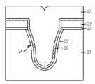
도 2a 내지 도 2d는 본 발명의 실시예에 따른 반도체소자의 소자분리 방법을 도시한 공정 단면도이다.2A through 2D are cross-sectional views illustrating a device isolation method of a semiconductor device in accordance with an embodiment of the present invention.
도 2a에 도시된 바와 같이, 실리콘기판(21) 상에 패드산화막(22)과 패드질화막(23)을 증착한 후, 패드질화막(23) 상에 포토레지스트를 이용하여 소자분리마스크(ISO mask, 도시생략)를 형성한다.As shown in FIG. 2A, after the
이어서, 소자분리마스크를 식각배리어로 하여 패드질화막(23)과 패드산화막(22)을 차례로 식각하여 소자분리영역이 형성될 실리콘기판(21) 표면을 노출시킨다.Subsequently, using the device isolation mask as an etching barrier, the
다음으로, 소자분리마스크를 제거한 후 패드산화막(22) 식각후 노출된 실리콘기판(21)의 표면을 식각하여 소자분리를 위한 트렌치(24)를 형성한다.Next, after removing the device isolation mask, the surface of the exposed
계속해서, 트렌치(24) 형성을 위한 식각공정시 발생된 트렌치(24) 바닥 및 측벽의 실리콘기판(21)의 손상을 제거하기 위해 희생산화 및 희생산화막 제거 공정을 진행하고, 이어서 측벽산화를 실시하여 트렌치(24)의 바닥 및 측벽에 측벽산화막(25)을 형성한다.Subsequently, the sacrificial oxidation and the sacrificial oxide film removing process are performed to remove the damage of the
이때, 측벽산화막(25)은 PMOS에서의 핫캐리어열화(hot carrier degradation)나 STI에서의 펀치쓰루누설열화(punch-through leakage degradation)를 방지하기 위해 후속 질화막라이너 아래에서 20Å∼50Å의 얇은 두께로 형성된다.At this time, the
다음으로, 측벽산화막(25)을 포함한 전면에 질화막라이너(26)를 형성한다. 이때, 질화막라이너(26)는 CVD(Chemical Vapor Deposition)을 이용하여 30Å∼150Å 두께로 증착한다. 예를 들어, 질화막라이너의 CVD 증착은 500℃∼800℃의 증착온도와 1torr∼200torr의 압력하에서 NH3 또는 N2 중에서 선택된 질소함유 가스와 SiH4 또는 SiH2Cl2 중에서 선택된 실리콘함유 가스를 이용한다.Next, a
도 2b에 도시된 바와 같이, 산화막라이너를 증착하지 않고 바로 HDP-CVD 공정을 통해 트렌치(24)를 매립하도록 질화막라이너(26) 상에 갭필산화막(27)을 증착한다. HDP-CVD 공정은 일반적인 CVD 공정에 비해 고밀도플라즈마를 이용하여 반응을 촉진시키므로 갭필 특성이 우수한 것으로 알려져 있다.As shown in FIG. 2B, the gap
상기한 갭필산화막(27) 증착시, 질화막라이너(26)의 산화를 최소화시키기 위해 즉, 산화막라이너없이도 질화막라이너(26)의 손실을 최소화시킬 수 있는 산소성분을 포함하지 않는 히팅스텝(heating step)을 갖는 HDP-CVD 공정을 적용해야 한 다.When the gap
HDP CVD 공정은 일반적으로 웨이퍼 로딩(Wafer loading) 스텝(step), 플라즈마 히팅(Plasma heating) 스텝, 증착(Deposition) 스텝 및 웨이퍼 언로딩(Wafer unloading) 스텝의 순서로 진행되는 시퀀스(Sequence)를 가지며, 이때 플라즈마 히팅 스텝시 케미스트리가 산소(Oxygen)를 주로 포함하는 성분이므로 노출된 질화막라이너 표면을 산화시키게 된다. 이러한 질화막라이너의 산화를 최소화하기 위해 플라즈마 히팅 스텝을 없애거나 감소시키면(산소 성분 감소), 증착스텝 초기의 웨이퍼 온도가 매우 낮아 라디칼들의 점착계수(Sticking coefficient)가 높아져서 갭필 성능을 악화시킨다.HDP CVD processes typically have a sequence that proceeds in the order of a wafer loading step, a plasma heating step, a deposition step, and a wafer unloading step. In this case, since the chemistry mainly contains oxygen during the plasma heating step, the exposed nitride film liner surface is oxidized. If the plasma heating step is eliminated or reduced to reduce the oxidation of the nitride film liner (reduced oxygen content), the wafer temperature at the beginning of the deposition step is very low, thereby increasing the sticking coefficient of radicals, thereby degrading the gapfill performance.
이와 같은 질화막라이너의 산화 또는 갭필성능 악화를 해결하기 위해 본 발명은 웨이퍼 히팅 스텝시 질화막라이너를 산화시키기 않고 웨이퍼를 히팅시킬 수 있는 케미스트리(Chemistry)를 사용하고자 한다.In order to solve the oxidation or gapfill performance deterioration of the nitride film liner, the present invention intends to use a chemistry that can heat the wafer without oxidizing the nitride film liner during the wafer heating step.
바람직하게, 웨이퍼 히팅 스텝시 케미스트리는 N2 또는 NH3와 같이 산소를 포함하지 않고 질소를 포함하는 질소함유 가스 케미스트리(Gas chemistry)가 가장 유리하다. 이와 같이, 질소함유 가스 케미스트리를 이용하여 플라즈마히팅스텝을 진행하면, 증착스텝 초기의 웨이퍼 온도를 유지하도록 하여 우수한 갭필 성능을 유지할 수 있다.Preferably, the chemistry at the wafer heating step is most advantageous with a nitrogen containing gas chemistry which does not contain oxygen, such as N2 or NH3 , but which contains nitrogen. As described above, when the plasma heating step is performed using the nitrogen-containing gas chemistry, excellent gap fill performance can be maintained by maintaining the wafer temperature at the initial stage of the deposition step.
본 발명의 실시예에 따른 HDP-CVD 공정은 후속 도 3을 참조하여 자세히 설명하기로 한다.The HDP-CVD process according to the embodiment of the present invention will be described in detail later with reference to FIG. 3.
도 2c에 도시된 바와 같이, 갭필산화막(27)의 평탄화를 위한 CMP(Chemical Mechanical Polishing) 공정을 패드질화막(23)을 연마정지막으로 하여 진행한다.As shown in FIG. 2C, a chemical mechanical polishing (CMP) process for planarization of the gap
도 2d에 도시된 바와 같이, 패드질화막(23)과 패드산화막(22)을 선택적으로 제거한다. 이때, 패드질화막(23)은 인산(H3PO4) 용액을 이용하여 식각하고, 패드산화막은 불산(HF) 용액을 이용하여 식각한다.As shown in FIG. 2D, the
상술한 실시예에 따른면, STI 구조의 소자분리막은 소정깊이를 갖는 트렌치(24), 트렌치(24)의 표면에 형성된 측벽산화막(25), 측벽산화막(25) 상에 형성된 질화막라이너(26) 및 질화막라이너(26) 상에 형성되어 트렌치(24)를 매립하는 갭필산화막(27)으로 이루어진다.According to the above-described embodiment, the device isolation film having the STI structure includes a
이하, 첨부도면 도 3을 참조하여 갭필산화막(27)을 증착하기 위한 HDP-CVD 공정, 즉 질소함유 가스 케미스트리를 도입하는 웨이퍼의 플라즈마히팅스텝을 포함하는 갭필산화막(27)의 HDP-CVD 공정에 대해 설명하기로 한다.Hereinafter, with reference to the accompanying drawings, the HDP-CVD process for depositing the gap
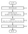
도 3은 본 발명의 실시예에 따른 갭필산화막의 HDP-CVD 공정의 시퀀스를 도시한 도면이다.3 is a diagram showing a sequence of an HDP-CVD process of a gapfill oxide film according to an embodiment of the present invention.
도 3을 참조하면, 갭필산화막의 HDP-CVD 공정은 웨이퍼 로딩스텝(31), 플라즈마 히팅 스텝(32), 증착 스텝(33) 및 웨이퍼 언로딩 스텝(34)의 순서로 진행되는 시퀀스를 갖는다.Referring to FIG. 3, the HDP-CVD process of the gap fill oxide film has a sequence of a
먼저, 질화막라이너가 형성된 웨이퍼를 HDP CVD 챔버내로 로딩시킨 후, 플라즈마히팅스텝(32)을 진행한다. 여기서, 플라즈마히팅스텝(32)은 웨이퍼의 온도를 일정온도가 되도록 가열시키기 위한 것이며, 이와 같이 웨이퍼를 플라즈마를 이용하여 가열시켜주므로써 갭필산화막의 우수한 갭필성능을 구현할 수 있는 증착온도를 확보한다.First, the wafer on which the nitride film liner is formed is loaded into the HDP CVD chamber, and then the
상기한 플라즈마히팅스텝(32)은, HDP CVD 챔버내에서 N2 또는 NH3와 같이 질소를 포함하는 질소함유가스를 이용한 플라즈마를 발생시켜 진행하는데, 플라즈마히팅 시간은 10초∼200초, N2의 유량은 1sccm∼1000sccm, NH3의 유량은 1sccm∼1000sccm, 플라즈마 생성 및 유지(generation and maintenance)를 위해 ICP 또는 TCP 소스에 1㎑∼10㎓의 주파수를 가지는 1000W∼10000W의 소스파워(Source RF power)를 인가하고, 생성된 플라즈마를 웨이퍼쪽으로 끌어당기기 위해 웨이퍼에 0W∼5000W의 바이어스파워(Bias RF power)를 인가한다.The
상기한 플라즈마히팅스텝(32)후에, 갭필산화막의 증착스텝(33)을 진행한다. 갭필산화막은 실리콘산화막(Silicon oxide)으로 증착하는데, HDP-CVD 공정을 이용한 실리콘산화막의 증착스텝은 잘 알려진 바와 같이 스퍼터링스텝(sputtering step)과 증착스텝(deposition step)으로 구성된다.After the
예컨대, HDP-CVD 챔버 내부의 압력을 0.001mtorr∼100mtorr로 유지하고, 1㎑∼10㎓의 범위로 발생시킨 플라즈마를 이용하여 스퍼터링스텝을 진행하고, 1㎑∼10㎓의 범위를 갖는 바이어스 파워를 공급하여 시스전압(sheath voltage)을 조절하여 스퍼터링을 조절한 후, 실란(SiH4) 또는 TEOS 중에서 선택된 실리콘소스가스와 O2, O3, N2O 또는 NO2 중에서 선택된 산소소스가스를 주입하여 실리콘산화막(Silicon oxide)을 증착한다.For example, the pressure inside the HDP-CVD chamber is maintained at 0.001 mtorr to 100 mtorr, and the sputtering step is performed using a plasma generated in the range of 1 kPa to 10 kPa, and a bias power having a range of 1 kPa to 10 kPa is obtained. After controlling the sputtering by adjusting the sheath voltage, a silicon source gas selected from silane (SiH4 ) or TEOS and an oxygen source gas selected from O2 , O3 , N2 O or NO2 are injected. Silicon oxide film is deposited.
상기한 바와 같이 일련의 공정에 의해 갭필산화막을 증착한 후에, 웨이퍼를 HDP-CVD 챔버 밖으로 빼내는 웨이퍼 언로딩 스텝(34)을 진행한다.After depositing the gapfill oxide film by a series of processes as described above, the
도 3과 같은 시퀀스를 이용하여 갭필산화막을 증착한 후에는, 갭필산화막의 치밀화를 위해 열처리 공정을 진행한다. 이때, 열처리 공정은 O2, N2, O3, N2O 또는 H2/O2의 혼합가스 분위기에서 퍼니스열처리(furnace annealing)하거나 급속열처리(Rapid Thermal Process)한다. 예컨대, 퍼니스열처리는 300℃∼1200℃로 5분∼10분동안 진행하고, 급속열처리는 600 ℃∼1000℃의 온도로 1초∼10초동안 진행한다.After the gap fill oxide film is deposited using the sequence as shown in FIG. 3, a heat treatment process is performed to densify the gap fill oxide film. At this time, the heat treatment process is furnace annealing or rapid thermal treatment in a mixed gas atmosphere of O2 , N2 , O3 , N2 O or H2 / O2 . For example, the furnace heat treatment proceeds for 5 minutes to 10 minutes at 300 ° C to 1200 ° C, and the rapid heat treatment proceeds for 1 second to 10 seconds at a temperature of 600 ° C to 1000 ° C.
상술한 실시예에서는 플라즈마히팅스텝시, 질소함유가스를 이용하여 플라즈마를 발생시켰으나, Ar, He, Ne 또는 Kr 중에서 선택된 비활성가스 또는 H2를 이용하여 플라즈마를 발생시켜 플라즈마히팅스텝을 진행하는 경우에도 동일한 효과를 얻을 수 있다. 여기서, 비활성가스 또는 H2는 반응(reaction)을 동반하지 않는 가스 케미스트리로 알려져 있으며, 이들의 가스 혼합(gas mixture)도 가능하다.In the above-described embodiment, the plasma is generated using the nitrogen-containing gas during the plasma heating step, but the plasma heating step is performed by generating the plasma by using the inert gas selected from Ar, He, Ne, or Kr or H2 . The same effect can be obtained. Here, the inert gas or H2 is known as a gas chemistry which does not accompany a reaction, and a gas mixture thereof is also possible.
한편, 본 발명과 같이 질화막라이너 위에 직접 HDP CVD 공정을 통해 갭필산화막을 증착하면 트렌치 바텀부분에서 질화막라이너의 일부가 스퍼터링(Sputtering)되어 제거되므로 질화막라이너 리프팅 문제가 근본적으로 방지된다.On the other hand, when the gap fill oxide film is deposited directly on the nitride film liner through the HDP CVD process, a portion of the nitride film liner is sputtered and removed at the trench bottom portion, thereby preventing the problem of lifting the nitride film liner.
그리고, 본 발명은 라이너산화막을 증착하지 않아도 되므로 그만큼 HDP-CVD 공정의 갭필마진이 증대되고, 이로써 활성영역의 폭을 확보하기 위한 패터닝 마진이 증가한다.In the present invention, since the liner oxide film does not need to be deposited, the gap fill margin of the HDP-CVD process is increased, thereby increasing the patterning margin for securing the width of the active region.
본 발명의 기술 사상은 상기 바람직한 실시예에 따라 구체적으로 기술되었으나, 상기한 실시예는 그 설명을 위한 것이며 그 제한을 위한 것이 아님을 주의하여야 한다. 또한, 본 발명의 기술 분야의 통상의 전문가라면 본 발명의 기술 사상의 범위 내에서 다양한 실시예가 가능함을 이해할 수 있을 것이다.Although the technical idea of the present invention has been described in detail according to the above preferred embodiment, it should be noted that the above-described embodiment is for the purpose of description and not of limitation. In addition, those skilled in the art will understand that various embodiments are possible within the scope of the technical idea of the present invention.
상술한 본 발명은 라이너산화막을 도입하지 않으면서 트렌치를 갭필산화막으로 매립함에 따라 HDP-CVD 공정의 갭필마진을 증대시킬 수 있는 효과가 있다.The present invention described above has the effect of increasing the gap fill margin of the HDP-CVD process by filling the trench with the gap fill oxide film without introducing the liner oxide film.
또한, 본 발명은 질화막라이너 위에 라이너산화막을 형성하지 않으므로 활성영역의 폭 확보를 위한 패터닝 마진을 증가시킬 수 있다.
In addition, since the liner oxide film is not formed on the nitride film liner, the patterning margin for securing the width of the active region can be increased.
Claims (16)
Translated fromKoreanPriority Applications (1)
| Application Number | Priority Date | Filing Date | Title |
|---|---|---|---|
| KR1020040049861AKR100599437B1 (en) | 2004-06-30 | 2004-06-30 | Device Separation Method of Semiconductor Devices |
Applications Claiming Priority (1)
| Application Number | Priority Date | Filing Date | Title |
|---|---|---|---|
| KR1020040049861AKR100599437B1 (en) | 2004-06-30 | 2004-06-30 | Device Separation Method of Semiconductor Devices |
Publications (2)
| Publication Number | Publication Date |
|---|---|
| KR20060000876Atrue KR20060000876A (en) | 2006-01-06 |
| KR100599437B1 KR100599437B1 (en) | 2006-07-12 |
Family
ID=37104100
Family Applications (1)
| Application Number | Title | Priority Date | Filing Date |
|---|---|---|---|
| KR1020040049861AExpired - Fee RelatedKR100599437B1 (en) | 2004-06-30 | 2004-06-30 | Device Separation Method of Semiconductor Devices |
Country Status (1)
| Country | Link |
|---|---|
| KR (1) | KR100599437B1 (en) |
Cited By (8)
| Publication number | Priority date | Publication date | Assignee | Title |
|---|---|---|---|---|
| KR101116727B1 (en)* | 2009-06-25 | 2012-02-22 | 주식회사 하이닉스반도체 | Method for forming insulating layer in semiconductor device |
| WO2013154867A1 (en)* | 2012-04-13 | 2013-10-17 | Lam Research Corporation | Layer-layer etch of non volatile materials |
| US9425041B2 (en) | 2015-01-06 | 2016-08-23 | Lam Research Corporation | Isotropic atomic layer etch for silicon oxides using no activation |
| US9431268B2 (en) | 2015-01-05 | 2016-08-30 | Lam Research Corporation | Isotropic atomic layer etch for silicon and germanium oxides |
| KR20220077675A (en)* | 2020-12-02 | 2022-06-09 | 주식회사 원익아이피에스 | Thin film formation method |
| US11380556B2 (en) | 2018-05-25 | 2022-07-05 | Lam Research Corporation | Thermal atomic layer etch with rapid temperature cycling |
| US11637022B2 (en) | 2018-07-09 | 2023-04-25 | Lam Research Corporation | Electron excitation atomic layer etch |
| US12280091B2 (en) | 2021-02-03 | 2025-04-22 | Lam Research Corporation | Etch selectivity control in atomic layer etching |
Family Cites Families (7)
| Publication number | Priority date | Publication date | Assignee | Title |
|---|---|---|---|---|
| JPH10214889A (en) | 1997-01-21 | 1998-08-11 | Siemens Ag | Method of forming thin film of crystalline silicon nitride film in shallow trench isolation structure, shallow trench isolation structure for submicron integrated circuit device, and crystalline silicon nitride film |
| KR19980082867A (en)* | 1997-05-09 | 1998-12-05 | 윤종용 | Device Separation Method of Semiconductor Device |
| KR100381849B1 (en)* | 2000-07-10 | 2003-05-01 | 삼성전자주식회사 | Trench isolation method |
| JP2002100670A (en) | 2000-09-22 | 2002-04-05 | Sanyo Electric Co Ltd | Semiconductor device and its manufacturing method |
| US6458722B1 (en)* | 2000-10-25 | 2002-10-01 | Applied Materials, Inc. | Controlled method of silicon-rich oxide deposition using HDP-CVD |
| KR100461330B1 (en)* | 2002-07-19 | 2004-12-14 | 주식회사 하이닉스반도체 | Method for forming Shallow Trench Isolation of semiconductor device |
| KR20050011190A (en)* | 2003-07-22 | 2005-01-29 | 주식회사 하이닉스반도체 | Fabricating method of trench isolation layer with low temperature plasma oxide in semiconductor device |
- 2004
- 2004-06-30KRKR1020040049861Apatent/KR100599437B1/ennot_activeExpired - Fee Related
Cited By (9)
| Publication number | Priority date | Publication date | Assignee | Title |
|---|---|---|---|---|
| KR101116727B1 (en)* | 2009-06-25 | 2012-02-22 | 주식회사 하이닉스반도체 | Method for forming insulating layer in semiconductor device |
| WO2013154867A1 (en)* | 2012-04-13 | 2013-10-17 | Lam Research Corporation | Layer-layer etch of non volatile materials |
| US9431268B2 (en) | 2015-01-05 | 2016-08-30 | Lam Research Corporation | Isotropic atomic layer etch for silicon and germanium oxides |
| US9425041B2 (en) | 2015-01-06 | 2016-08-23 | Lam Research Corporation | Isotropic atomic layer etch for silicon oxides using no activation |
| US10679868B2 (en) | 2015-01-06 | 2020-06-09 | Lam Research Corporation | Isotropic atomic layer etch for silicon oxides using no activation |
| US11380556B2 (en) | 2018-05-25 | 2022-07-05 | Lam Research Corporation | Thermal atomic layer etch with rapid temperature cycling |
| US11637022B2 (en) | 2018-07-09 | 2023-04-25 | Lam Research Corporation | Electron excitation atomic layer etch |
| KR20220077675A (en)* | 2020-12-02 | 2022-06-09 | 주식회사 원익아이피에스 | Thin film formation method |
| US12280091B2 (en) | 2021-02-03 | 2025-04-22 | Lam Research Corporation | Etch selectivity control in atomic layer etching |
Also Published As
| Publication number | Publication date |
|---|---|
| KR100599437B1 (en) | 2006-07-12 |
Similar Documents
| Publication | Publication Date | Title |
|---|---|---|
| KR101161098B1 (en) | Gapfill improvement with low etch rate dielectric liners | |
| US6719012B2 (en) | Method of forming trench isolation regions | |
| KR100536604B1 (en) | Method of gap-fill using a high density plasma deposision | |
| KR100655845B1 (en) | Trench insulation method | |
| KR100788183B1 (en) | Ozone post-deposition treatment to remove carbon in a flowable oxide film | |
| US20060099771A1 (en) | Selective nitride liner formation for shallow trench isolation | |
| KR100541680B1 (en) | Device Separating Method of Semiconductor Device | |
| KR100599437B1 (en) | Device Separation Method of Semiconductor Devices | |
| US20090181516A1 (en) | Method of Forming Isolation Layer of Semiconductor Device | |
| KR101025730B1 (en) | Device Separation Method of Semiconductor Devices | |
| KR100524805B1 (en) | Method for gapfilling trench in semiconductor device | |
| KR20040036858A (en) | Method for forming isolation layer in semiconductor device | |
| KR100376875B1 (en) | Method for forming isolation layer in semiconductor device | |
| KR20010106956A (en) | Method for preventing bubble defect in trench of semiconductor device | |
| KR100905997B1 (en) | Trench type isolation layer formation method of semiconductor device | |
| KR100533966B1 (en) | Isolation by trench type and method for manufacturing the same | |
| KR100531122B1 (en) | Shallow Trench Isolation Method For Semiconductor Devices | |
| KR100528165B1 (en) | Fabricating method of forming isolation layer in dram device using hdp cvd process | |
| KR100842883B1 (en) | Device isolation region formation method of semiconductor device | |
| KR20030088235A (en) | Method for forming isolation layer of semiconductor device | |
| KR100924544B1 (en) | Device Separating Method of Semiconductor Device | |
| KR100842901B1 (en) | Device Separating Method of Semiconductor Device | |
| KR100876874B1 (en) | Device Separating Method of Semiconductor Device | |
| KR20050003009A (en) | Method for forming trench type isolation layer in semiconductor device | |
| KR20020002603A (en) | Method for forming isolation in semiconductor device |
Legal Events
| Date | Code | Title | Description |
|---|---|---|---|
| A201 | Request for examination | ||
| PA0109 | Patent application | St.27 status event code:A-0-1-A10-A12-nap-PA0109 | |
| PA0201 | Request for examination | St.27 status event code:A-1-2-D10-D11-exm-PA0201 | |
| D13-X000 | Search requested | St.27 status event code:A-1-2-D10-D13-srh-X000 | |
| PG1501 | Laying open of application | St.27 status event code:A-1-1-Q10-Q12-nap-PG1501 | |
| D14-X000 | Search report completed | St.27 status event code:A-1-2-D10-D14-srh-X000 | |
| E902 | Notification of reason for refusal | ||
| PE0902 | Notice of grounds for rejection | St.27 status event code:A-1-2-D10-D21-exm-PE0902 | |
| E13-X000 | Pre-grant limitation requested | St.27 status event code:A-2-3-E10-E13-lim-X000 | |
| P11-X000 | Amendment of application requested | St.27 status event code:A-2-2-P10-P11-nap-X000 | |
| P13-X000 | Application amended | St.27 status event code:A-2-2-P10-P13-nap-X000 | |
| E701 | Decision to grant or registration of patent right | ||
| PE0701 | Decision of registration | St.27 status event code:A-1-2-D10-D22-exm-PE0701 | |
| GRNT | Written decision to grant | ||
| PR0701 | Registration of establishment | St.27 status event code:A-2-4-F10-F11-exm-PR0701 | |
| PR1002 | Payment of registration fee | St.27 status event code:A-2-2-U10-U11-oth-PR1002 Fee payment year number:1 | |
| PG1601 | Publication of registration | St.27 status event code:A-4-4-Q10-Q13-nap-PG1601 | |
| PR1001 | Payment of annual fee | St.27 status event code:A-4-4-U10-U11-oth-PR1001 Fee payment year number:4 | |
| FPAY | Annual fee payment | Payment date:20100624 Year of fee payment:5 | |
| PR1001 | Payment of annual fee | St.27 status event code:A-4-4-U10-U11-oth-PR1001 Fee payment year number:5 | |
| LAPS | Lapse due to unpaid annual fee | ||
| PC1903 | Unpaid annual fee | St.27 status event code:A-4-4-U10-U13-oth-PC1903 Not in force date:20110705 Payment event data comment text:Termination Category : DEFAULT_OF_REGISTRATION_FEE | |
| PN2301 | Change of applicant | St.27 status event code:A-5-5-R10-R13-asn-PN2301 St.27 status event code:A-5-5-R10-R11-asn-PN2301 | |
| PC1903 | Unpaid annual fee | St.27 status event code:N-4-6-H10-H13-oth-PC1903 Ip right cessation event data comment text:Termination Category : DEFAULT_OF_REGISTRATION_FEE Not in force date:20110705 | |
| PN2301 | Change of applicant | St.27 status event code:A-5-5-R10-R13-asn-PN2301 St.27 status event code:A-5-5-R10-R11-asn-PN2301 | |
| PN2301 | Change of applicant | St.27 status event code:A-5-5-R10-R13-asn-PN2301 St.27 status event code:A-5-5-R10-R11-asn-PN2301 | |
| P22-X000 | Classification modified | St.27 status event code:A-4-4-P10-P22-nap-X000 |