KR200489059Y1 - Apparatus for excrements disposal - Google Patents
Apparatus for excrements disposalDownload PDFInfo
- Publication number
- KR200489059Y1 KR200489059Y1KR2020180000321UKR20180000321UKR200489059Y1KR 200489059 Y1KR200489059 Y1KR 200489059Y1KR 2020180000321 UKR2020180000321 UKR 2020180000321UKR 20180000321 UKR20180000321 UKR 20180000321UKR 200489059 Y1KR200489059 Y1KR 200489059Y1
- Authority
- KR
- South Korea
- Prior art keywords
- stirring
- manure
- unit
- bracket
- present
- Prior art date
- Legal status (The legal status is an assumption and is not a legal conclusion. Google has not performed a legal analysis and makes no representation as to the accuracy of the status listed.)
- Active
Links
Images


Classifications
- B—PERFORMING OPERATIONS; TRANSPORTING
- B01—PHYSICAL OR CHEMICAL PROCESSES OR APPARATUS IN GENERAL
- B01F—MIXING, e.g. DISSOLVING, EMULSIFYING OR DISPERSING
- B01F27/00—Mixers with rotary stirring devices in fixed receptacles; Kneaders
- B01F27/05—Stirrers
- B01F27/051—Stirrers characterised by their elements, materials or mechanical properties
- B01F27/054—Deformable stirrers, e.g. deformed by a centrifugal force applied during operation
- B01F27/0541—Deformable stirrers, e.g. deformed by a centrifugal force applied during operation with mechanical means to alter the position of the stirring elements
- B01F7/00058—
- B01F15/00779—
- B01F15/00824—
- B—PERFORMING OPERATIONS; TRANSPORTING
- B01—PHYSICAL OR CHEMICAL PROCESSES OR APPARATUS IN GENERAL
- B01F—MIXING, e.g. DISSOLVING, EMULSIFYING OR DISPERSING
- B01F27/00—Mixers with rotary stirring devices in fixed receptacles; Kneaders
- B01F27/80—Mixers with rotary stirring devices in fixed receptacles; Kneaders with stirrers rotating about a substantially vertical axis
- B01F27/91—Mixers with rotary stirring devices in fixed receptacles; Kneaders with stirrers rotating about a substantially vertical axis with propellers
- B—PERFORMING OPERATIONS; TRANSPORTING
- B01—PHYSICAL OR CHEMICAL PROCESSES OR APPARATUS IN GENERAL
- B01F—MIXING, e.g. DISSOLVING, EMULSIFYING OR DISPERSING
- B01F35/00—Accessories for mixers; Auxiliary operations or auxiliary devices; Parts or details of general application
- B01F35/45—Closures or doors specially adapted for mixing receptacles; Operating mechanisms therefor
- B—PERFORMING OPERATIONS; TRANSPORTING
- B01—PHYSICAL OR CHEMICAL PROCESSES OR APPARATUS IN GENERAL
- B01F—MIXING, e.g. DISSOLVING, EMULSIFYING OR DISPERSING
- B01F35/00—Accessories for mixers; Auxiliary operations or auxiliary devices; Parts or details of general application
- B01F35/50—Mixing receptacles
- B01F7/22—
Landscapes
- Chemical & Material Sciences (AREA)
- Chemical Kinetics & Catalysis (AREA)
- Fertilizers (AREA)
- Mixers Of The Rotary Stirring Type (AREA)
- Treatment Of Sludge (AREA)
Abstract
Translated fromKoreanDescription
Translated fromKorean본 고안은 분뇨 처리장치에 관한 것으로서, 더욱 상세하게는 고장 발생률이 매우 낮으며, 고장이 발생될 경우 외부에서 수리나 교체가 가능하도록 한 분뇨 처리장치에 관한 것이다.The present invention relates to a manure processing device, and more particularly, to a failure rate is very low, and to a manure processing device that can be repaired or replaced from the outside when a failure occurs.
최근에는 환경오염에 대한 심각성으로 인하여 축산농가에서도 가축의 배설물인 분뇨를 별도의 처리과정을 거쳐 처리하도록 되어 있고, 이와 같은 규정으로 축산농가에서는 분뇨를 처리하기 전 대형 저장탱크에 분뇨를 모아 저장해둔다.In recent years, due to the seriousness of environmental pollution, livestock farms are required to process manure, which is the excretion of livestock, through a separate treatment process.As such, livestock farms collect and store manure in large storage tanks before manure is processed. .
이와 같이 대형 저장탱크에 저장된 가축의 분뇨는 저장과정 중에 정체되어 있는 것이어서 슬러지는 가라앉고 비교적 가벼운 물만이 위쪽에 뜬 상태로 오랫동안 보관된다.As such, manure of livestock stored in large storage tanks is stagnant during the storage process, so that the sludge subsides and is stored for a long time with only relatively light water floating on the top.
따라서, 분뇨저장탱크에 저장된 분뇨를 이송하기 위하여 펌프 등으로 빨아들일 때 저장탱크 위쪽에 위치된 물은 잘 빨아 들여지지만 아래쪽에 가라앉은 슬러지는 잘 빨아들여지지 않아 펌프 등의 고장 원인이 되었다.Therefore, when the manure is stored in the manure storage tank by the pump or the like to transport the manure, the water located above the storage tank is sucked well, but the sludge settled below is not sucked well, causing a failure of the pump and the like.
이와 같은 문제점으로, 공개특허공보 제10-2001-0079580호(분뇨 저장 및 발효 탱크)에서와 같이 저장탱크 내의 분뇨를 교반하도록 된 기술이 안출되었다.With this problem, a technique has been devised to stir manure in a storage tank, as in JP-A-10-2001-0079580 (a manure storage and fermentation tank).
그러나, 상기와 같은 교반 장치 및 방법은, 강한 산소를 분사하여 저장탱크 내의 분뇨를 교반하는 것으로서, 그 교반 효과가 기대에 미치지 못할 뿐 아니라 장치가 분뇨에 오랫동안 잠겨있는 것이어서 부식이 급속하게 진행되어 잦은 수리가 요구되는 문제점이 있다.However, the stirring device and method as described above, by stirring strong oxygen to agitate the manure in the storage tank, the agitation effect does not meet expectations, the device is immersed in the manure for a long time, so that the corrosion progresses rapidly and frequently There is a problem that requires repair.
또한, 저장탱크 내에 분뇨가 저장되어 있는 상태에서 고장이 발생될 경우에는 수리가 어려운 문제점도 있다.In addition, when a failure occurs in the state in which the manure is stored in the storage tank there is a problem that is difficult to repair.
본 고안은 상기한 문제점을 해결하기 위해 안출된 것으로서, 고장 발생률이 매우 낮으며, 고장이 발생될 경우 외부에서 수리나 교체가 가능하도록 하므로써, 사용상의 편의성을 향상시킬 수 있는 분뇨 처리장치를 제공하는데 그 목적이 있다.The present invention was devised to solve the above problems, the failure rate is very low, and when a failure occurs, by providing a repair or replacement from the outside, to provide a manure treatment device that can improve the convenience of use. The purpose is.
본 고안에 따른 분뇨 처리장치는, 상면에 개구부와 설치홀이 형성되고, 내부에는 분뇨가 저장되는 저장공간이 형성된 저장부, 상기 개구부를 밀폐하도록 상기 저장부에 설치되는 밀폐부, 상기 설치홀에 설치되며 상기 저장공간에 존재하는 분뇨를 교반하는 교반부를 포함한다.The manure processing device according to the present invention has an opening and an installation hole formed in an upper surface thereof, and a storage part having a storage space in which manure is stored therein, a sealing part installed in the storage part to seal the opening, in the installation hole. It is installed and includes a stirring unit for stirring the manure present in the storage space.
그리고, 상기 교반부를 수평방향으로 이동시켜 위치를 조절하기 위한 위치조절부를 더 포함하고,And, further comprising a position adjusting unit for adjusting the position by moving the stirring unit in a horizontal direction,
상기 위치조절부는,The position adjusting unit,
상기 설치홀에 설치되고 서로 마주하는 내측면에는 레일부가 각각 형성된 이동가이드, 상기 이동가이드의 내부에 배치되어 상기 교반부를 지지하며, 양측에는 상기 레일부를 따라 슬라이딩 이동되는 슬라이딩부가 형성된 브라켓을 포함한다.Inner surfaces installed in the installation holes and facing each other may include a movement guide having rail portions respectively formed therein, and a bracket having sliding portions slidingly moved along the rail portion at both sides to support the stirring portion.
또한, 상기 이동가이드를 상,하 방향으로 이동시켜 상기 교반부의 높낮이를 조절하는 높낮이조절부를 더 포함한다.In addition, the movement guide further comprises a height adjustment unit for adjusting the height of the stirring unit by moving in the up, down direction.
그리고, 상기 교반부는,And, the stirring unit,
상기 브라켓에 지지되는 모터, 상기 모터의 동력으로 제자리 회전되는 회전축, 상기 회전축과 함께 회전되면서 상기 저장공간 내의 분뇨를 교반하는 교반날개부를 포함한다.It includes a motor supported by the bracket, a rotary shaft rotated in place by the power of the motor, a stirring blade portion for stirring the manure in the storage space while being rotated with the rotary shaft.
또한, 상기 브라켓에는 상기 회전축이 관통하는 관통홀이 수직 방향으로 형성되고,In addition, the bracket has a through hole through which the rotating shaft penetrates in a vertical direction,
상기 모터의 저면에 결합되며, 반원형 형상으로 형성되어 상기 브라켓의 상면에 안착된 상태에서 회동될 수 있는 각도조절부를 더 포함한다.It is coupled to the bottom of the motor, is formed in a semi-circular shape further comprises an angle adjusting portion that can be rotated in a state seated on the upper surface of the bracket.
본 고안에 따른 분뇨 처리장치는, 고장 발생률이 매우 낮으며, 고장이 발생될 경우 외부에서 수리나 교체가 가능하여 사용상의 편의성을 향상시킬 수 있는 효과가 있다.The manure treatment device according to the present invention has a very low incidence of failure, and when a failure occurs, repair or replacement is possible from the outside, thereby improving convenience of use.
그리고, 분뇨 교반을 위한 교반부의 위치 조절과 높낮이 조절 및 각도 조절이 가능하여 어느 특정 영역에 가축분뇨가 많이 쌓일 경우, 해당 영역의 가축분뇨를 용이하게 교반할 수 있는 효과가 있다.In addition, the position control and height adjustment and angle adjustment of the stirring section for manure agitation is possible, if a lot of livestock manure in a specific area, there is an effect that can easily stir the livestock manure in the area.
또한, 교반부의 높낮이 조절이 가능하므로, 가축분뇨를 교반하지 않을 시, 교반부를 상승시켜 가축분뇨와 접촉되지 않도록 할 수 있음에 따라 부식을 방지할 수 있는 효과가 있다.In addition, since the height of the stirring unit can be adjusted, when the manure is not stirred, the stirring unit can be raised to prevent contact with the livestock manure, thereby preventing corrosion.
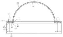
도 1은 본 고안에 따른 분뇨 처리장치를 도시한 정면도.
도 2는 본 고안에 따른 분뇨 처리장치를 도시한 분해 사시도.
도 3 및 도 4는 본 고안에 따른 분뇨 처리장치를 도시한 단면도.
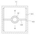
도 5는 본 고안에 따른 분뇨 처리장치에 적용된 위치조절부를 도시한 평단면도.
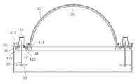
도 6은 본 고안에 따른 분뇨 처리장치에 높낮이조절부가 적용된 예를 도시한 단면도.
도 7은 본 고안에 따른 분뇨 처리장치에 적용된 높낮이조절부의 작동을 도시한 도.
도 8은 본 고안에 따른 분뇨 처리장치에 각도조절부가 적용된 예를 도시한 단면도.
도 9는 본 고안에 따른 분뇨 처리장치에 적용된 각도조절부의 작동을 도시한 도.1 is a front view showing a manure processing device according to the present invention.
Figure 2 is an exploded perspective view showing a manure treatment device according to the present invention.
3 and 4 is a cross-sectional view showing the manure treatment device according to the present invention.
Figure 5 is a cross-sectional view showing a position adjusting portion applied to the manure treatment device according to the present invention.
Figure 6 is a cross-sectional view showing an example of the height adjustment unit applied to the manure treatment device according to the present invention.
7 is a view showing the operation of the height adjustment unit applied to the manure treatment device according to the present invention.
Figure 8 is a sectional view showing an example in which the angle adjustment unit is applied to the manure processing device according to the present invention.
9 is a view showing the operation of the angle adjustment unit applied to the manure treatment device according to the present invention.
본 고안의 이점 및 특징, 그리고 그것들을 달성하는 방법은 첨부되는 도면과 함께 상세하게 후술되어 있는 실시예들을 참조하면 명확해질 것이다.Advantages and features of the present invention, and methods for achieving them will be apparent with reference to the embodiments described below in detail with the accompanying drawings.
그러나 본 고안은 이하에서 개시되는 실시예들에 한정되는 것이 아니라 서로 다른 다양한 형태로 구현될 수 있으며, 단지 본 실시예들은 본 고안의 개시가 완전하도록 하고, 본 고안이 속하는 기술분야에서 통상의 지식을 가진 자에게 고안의 범주를 완전하게 알려주기 위해 제공되는 것이며, 본 고안은 청구항의 범주에 의해 정의될 뿐이다. 명세서 전체에 걸쳐 동일 참조 부호는 동일 구성 요소를 지칭한다.However, the present invention is not limited to the embodiments disclosed below, but can be implemented in a variety of different forms, only the embodiments of the present invention to complete the disclosure of the present invention, it is common knowledge in the art It is provided to fully inform the person having the scope of the invention, which is only defined by the scope of the claims. Like reference numerals refer to like elements throughout.
이하, 본 고안의 실시예들에 의하여 분뇨 처리장치를 설명하기 위한 도면들을 참고하여 본 고안에 대해 설명하도록 한다.Hereinafter, the present invention will be described with reference to the drawings for describing a manure treatment device according to embodiments of the present invention.
도 1은 본 고안에 따른 분뇨 처리장치를 도시한 정면도이고, 도 2는 본 고안에 따른 분뇨 처리장치를 도시한 분해 사시도이며, 도 3 및 도 4는 본 고안에 따른 분뇨 처리장치를 도시한 단면도이고, 도 5는 본 고안에 따른 분뇨 처리장치에 적용된 위치조절부를 도시한 평단면도이며, 도 6은 본 고안에 따른 분뇨 처리장치에 높낮이조절부가 적용된 예를 도시한 단면도이고, 도 7은 본 고안에 따른 분뇨 처리장치에 적용된 높낮이조절부의 작동을 도시한 도이다.1 is a front view showing a manure processing device according to the present invention, Figure 2 is an exploded perspective view showing a manure processing device according to the present invention, Figure 3 and Figure 4 is a cross-sectional view showing a manure processing device according to the present invention. 5 is a cross-sectional view showing a position control unit applied to the manure processing device according to the present invention, Figure 6 is a cross-sectional view showing an example in which the height adjustment unit is applied to the manure processing device according to the present invention, Figure 7 Figure showing the operation of the height adjustment unit applied to the manure treatment device according to.
본 고안은 분뇨를 교반하여 처리함에 있어, 분뇨 교반기를 용이하게 교체하거나 보수할 수 있도록 한 분뇨 처리장치(1)이다.The present invention is a manure processing device (1) to make it easy to replace or repair the manure stirrer in the treatment of the manure by stirring.
이러한 분뇨 처리장치(1)는 가축 분뇨가 저장되는 저장부(10), 상기 저장부(10)를 밀폐시키는 밀폐부(20), 상기 저장부(10) 내의 분뇨를 교반하는 교반부(30)를 포함할 수 있다.The
상기 저장부(10)는 상면에 개구부(10a)가 형성되고, 내부에 분뇨가 저장되는 저장공간이 형성된 함체 구조이며, 상기 개구부(10a)의 가장자리에는 사람이 통행할 수 있는 바닥부가 형성된다.The
그리고, 상기 바닥부에는 후술되는 교반부(30)를 설치할 수 있도록 설치홀(10b)이 형성된다.In addition, the bottom portion is provided with an
즉, 상기 설치홀(10b)은 상기 저장공간과 연결되며, 상기 교반부(30)가 설치홀(10b)에 설치된 상태에서 저장공간 내의 분뇨를 교반하게 되는 것이다.That is, the installation hole (10b) is connected to the storage space, it is to stir the manure in the storage space in the state in which the stirring
상기 밀폐부(20)는 상기 저장공간에서 발생되는 가스와 냄새가 외부로 새어나가는 것을 방지하는 것으로, 상기 개구부(10a)를 밀폐하도록 바닥부의 설치된다.The sealing
구체적으로, 상기 저장부(10)의 상측에는 곡선형상으로 형성되며 금속재질로 제작되는 다수개의 골조(70)가 설치되고, 상기 밀폐부(20)로 상기 골조를 덮어 상기 개구부(10a)를 밀폐시킬 수 있다.Specifically, a plurality of
그리고, 상기 밀폐부(20)의 하측 가장자리는 상기 바닥부의 상면에 볼트나 접착제 등의 결합수단을 통해 고정될 수 있다.In addition, the lower edge of the
상기 교반부(30)는 상기 저장공간에 존재하는 가축 분뇨를 교반하는 것으로, 종래 가스포에 의해 감싸여지도록 분뇨저장탱크의 내부에 교반부(30)를 설치하는 분뇨 처리장치와는 다르게, 밀폐부(20)의 외부에 설치된다는 점에서 특징이 있다.The stirring
즉, 본 고안은 고장 발생률이 비교적 높은 교반부(30)를 저장부(10)의 외부에서 설치하여, 교반부(30)에 고장이 발생될 경우 밀폐부(20)를 걷어 내지 않고도 수리가 가능하도록 하므로서, 사용상의 편의성을 제공할 수 있다.That is, the present invention is installed outside the
이러한 교반부(30)는 모터(31), 회전축(32), 교반날개부(33)를 포함할 수 있다.The stirring
상기 모터(31)는 상기 설치홀(10b) 상에서 회전축(32)에 회전 동력을 제공하는 것으로, 모터(31)축이 정 방향 또는 역 방향으로 회전되는 공지의 DC모터(31) 또는 AC모터(31)로 형성될 수 있다.The
상기 회전축(32)은 상기 모터(31)축에 결합되어 저장공간에 위치되며, 상기 모터(31)의 동력으로 제자리 회전된다.The
상기 교반날개부(33)는 상기 저장공간에 존재하는 분뇨를 실제로 교반하는 것으로, 상기 회전축(32)의 하측에 장착되어 저장공간에 위치된다.The stirring
상기 교반날개부(33)는 프로펠러 형상으로 형성되어, 상기 모터(31)에 의해 회전되는 회전축(32)과 함께 제자리 회전되면서 저장공간 내의 분뇨를 교반한다.The stirring
상기 교반부(30)는 상기 저장공간 내의 분뇨를 고루게 교반할 수 있도록 다수개로 적용될 수 있다.The stirring
이상 설명한 교반부(30)는 위치조절부(40)에 의해 위치가 조절될 수 있다.The stirring
상기 위치조절부(40)는 상기 교반부(30)를 수평방향으로 이동시키기 위한 것으로, 이동가이드(41), 브라켓(42)을 포함할 수 있다.The position adjusting unit 40 is for moving the
상기 이동가이드(41)는 직사각형 틀 형상으로 형성되며, 상기 설치홀(10b)에 볼트, 피스 등을 통해 고정된다.The
도 5를 기준으로 상기 이동가이드(41)의 우측과 좌측의 마주하는 면에는 교반부(30)의 수평이동을 안내하기 위한 레일부(411)가 형성된다.5,
상기 브라켓(42)은 상기 이동가이드(41)의 내부공간에 배치되어, 상기 모터(31)를 지지한다.The
이때, 상기 브라켓(42)에는 상기 회전축(32)을 통과시키기 위한 관통홀(42a)이 수직방향으로 형성된다.At this time, the
그리고, 상기 브라켓(42)의 양측에는 상기 이동가이드(41)의 내면과 접촉되는 'ㄱ'자 형상의 돌출편(422)이 형성되고, 상기 돌출편(422)의 일측에는 상기 레일부(411)를 따라 슬라이딩 이동되는 슬라이딩부(421)가 형성된다.And, both sides of the
따라서, 교반 효율에 따라 교반부(30)의 위치를 변경하고자 할 경우, 상기 브라켓(42)을 이동가이드(41)의 일측 또는 타측으로 이동시켜 교반부(30)의 위치를 조절할 수 있다.Therefore, when the position of the stirring
예를 들면, 저장공간 중 어느 특정 영역에 가축분뇨가 비교적 많이 쌓이게 되는 현상이 발생될 경우, 상기 위치조절부(40)를 통해 상기 교반부(30)를 해당 영역으로 이동시켜 교반할 수 있다.For example, when a phenomenon in which a large amount of livestock manure is accumulated in a certain area of the storage space occurs, the
부가적으로, 상기 교반부(30)는 높낮이조절부(50)를 통해 높낮이가 조절될 수 있다.In addition, the stirring
상기 높낮이조절부(50)는 2개 한 쌍으로 구성되어 상기 이동가이드(41)의 일측과 타측에 각각 배치된다.The
상기 높낮이조절부(50)는 유압 또는 공압이 공급되거나 배출됨에 따라 피스톤이 상승 또는 하강되는 유압실린더 또는 공압실린더로 형성될 수 있다.The
이때, 높낮이조절부(50)가 적용되는 경우 상기 이동가이드(41)부는 볼트, 피스 등을 통해 고정되는 것이 아니라, 설치홀(10b)에 단순히 수용되어, 상,하 방향으로 자유롭게 승강될 수 있는 구조를 갖는다.In this case, when the
상기 높낮이조절부(50)는 상기 바닥부의 상면에 고정되며, 피스톤이 상기 이동가이드(41)의 상부 양측에 형성된 플랜지(412)에 결합된다.The
따라서, 상기 높낮이조절부(50)에 유압 또는 공압을 공급하면 상기 위치조절부(40) 및 교반부(30) 전체가 상승되고, 이와 반대로 높낮이조절부(50)에 공급되었던 유압 또는 공압을 배출시키면 상기 위치조절부(40) 및 교반부(30) 전체가 하강된다.Therefore, when hydraulic pressure or pneumatic pressure is supplied to the
즉, 본 고안은 가축분뇨의 교반 효율에 따라 교반부(30)의 높낮이를 용이하게 조절하여 가축분뇨의 교반효과를 우수하게 할 수 있다.That is, the present invention can easily adjust the height of the stirring
아울러, 가축분뇨를 교반하는 과정에서 상기 높낮이조절부(50)를 작동시켜 교반부(30)가 반복적으로 승강되도록 하면 가축분뇨를 보다 고루게 교반할 수 있을 것이다.In addition, by operating the
그리고, 교반부(30)의 높낮이 조절이 가능하므로, 가축분뇨를 교반하지 않을 시, 교반부(30)를 상승시켜 가축분뇨와 접촉되지 않도록 할 수 있음에 따라 부식을 방지할 수 있다.In addition, since the height of the stirring
다음으로 본 고안에 따른 분뇨 처리장치의 다른 실시예를 설명한다.Next, another embodiment of the manure processing device according to the present invention will be described.
도 8은 본 고안에 따른 분뇨 처리장치에 각도조절부가 적용된 예를 도시한 단면도이고, 도 9는 본 고안에 따른 분뇨 처리장치에 적용된 각도조절부의 작동을 도시한 도이다.8 is a cross-sectional view showing an example in which the angle adjustment unit is applied to the manure processing device according to the present invention, Figure 9 is a view showing the operation of the angle adjustment unit applied to the manure processing device according to the present invention.
본 실시예에서는 각도조절부(60)를 통해 상기 교반부(30)를 회동시켜 교반효율을 향상시킬 수 있도록 한다는 점에서 특징이 있다.In this embodiment, there is a feature in that the stirring
상기 각도조절부(60)는 대략 반원형 형상으로 형성될 수 있으며, 평평한 상면이 상기 모터(31)의 저면에 결합된다.The
그리고, 상기 각도조절부(60)에는 상기 회전축(32)이 통과하는 통과홀(61)이 수직 방향으로 형성된다.In addition, a
상기 각도조절부(60)는 상기 관통홀(42a)에 수용되고, 가장자리가 상기 브라켓(42)의 상면에 안착된다.The
상기 각도조절부(60)는 상기 모터(31)의 상측에 수평방향으로 연결되는 실린더(80)에 의해 회동되어 상기 교반부(30)의 각도가 변경되도록 한다.The
즉, 도 8 또는 도 9와 같이 상기 실린더(80)에 유압이나 공압을 공급 또는 배출시키면 상기 피스톤이 인출되거나 인입되면서 상기 교반부(30)를 해당 방향으로 회동시키는 것이다.That is, when supplying or discharging hydraulic pressure or pneumatic pressure to the
따라서, 교반 효율에 따라 교반부(30)의 각도를 변경하고자 할 경우, 실린더(80)를 작동시켜 교반부(30)의 교반각도를 조절할 수 있다.Therefore, when the angle of the stirring
예를 들면, 저장공간 중 어느 특정 영역에 가축분뇨가 비교적 많이 쌓이게 되는 현상이 발생될 경우, 상기 실린더 및 각도조절부(60)를 통해 상기 교반부(30)를 해당 영역으로 회동시켜 교반할 수 있어, 가축분뇨의 교반효율을 향상시킬 있다.
그리고, 이와 같이 교반부(30)를 해당 영역으로 회동시키기 위해서는 실린더(80)의 위치를 선택적으로 변경하여 설치하면 된다.
즉, 상기 실린더(80)를 모터(31)의 전측이나 후측, 좌측이나 우측, 대각선 방향에 위치되도록 선택적으로 연결해가면서 교반부(30)를 전,후 방향, 좌,우 방향, 대각선 방향으로 회동시킬 수 있는 것이다.
또한, 상기 실린더(80)는 생략될 수 있으며, 이와 같은 경우 관리자나 작업자가 직접 모터(31)를 전,후,좌,우, 대각선 방향으로 밀거나 당겨서 각도조절부(60), 회전축(32), 교반날개부(33)의 각도를 다양하게 조절할 수 있다.For example, when a phenomenon in which a large amount of livestock manure is accumulated in a specific area of the storage space occurs, the stirring
And in order to rotate the stirring
That is, while the
In addition, the
본 고안이 속하는 기술분야의 통상의 지식을 가진 자는 본 고안이 그 기술적 사상이나 필수적인 특징을 변경하지 않고서 다른 구체적인 형태로 실시될 수 있다는 것을 이해할 수 있을 것이다. 그러므로 이상에서 기술한 실시예들은 모든 면에서 예시적인 것이며 한정적이 아닌 것으로 이해해야만 한다. 본 고안의 범위는 상기 상세한 설명보다는 후술하는 특허청구의 범위에 의하여 나타내어지며, 특허청구의 범위의 의미 및 범위 그리고 그 균등 개념으로부터 도출되는 모든 변경 또는 변형된 형태가 본 고안의 범위에 포함되는 것으로 해석되어야 한다.Those skilled in the art to which the present invention pertains will understand that the present invention can be embodied in other specific forms without changing the technical spirit or essential features. Therefore, it should be understood that the embodiments described above are exemplary in all respects and not restrictive. The scope of the present invention is represented by the scope of the claims to be described later rather than the detailed description, and all changes or modifications derived from the meaning and scope of the claims and equivalent concepts are included in the scope of the invention. Should be interpreted.
1 : 분뇨 처리장치 10 : 저장부
10a : 개구부 10b : 설치홀
20 : 밀폐부 30 : 교반부
31 : 모터 32 : 회전축
33 : 교반날개부 40 : 위치조절부
41 : 이동가이드 411 : 레일부
42 : 브라켓 42a : 관통홀
421 : 슬라이딩부 50 : 높낮이조절부
60 : 각도조절부1: manure treatment device 10: storage unit
10a:
20: sealed portion 30: stirring portion
31: motor 32: rotating shaft
33: stirring blade 40: position adjusting unit
41: movement guide 411: rail portion
42
421: sliding part 50: height adjustment unit
60: angle adjuster
Claims (5)
Translated fromKorean상기 개구부를 밀폐하도록 상기 저장부에 설치되는 밀폐부,
상기 설치홀에 설치되며 상기 저장공간에 존재하는 분뇨를 교반하는 교반부,
상기 교반부를 수평방향으로 이동시켜 위치를 조절하는 위치조절부를 포함하고,
상기 위치조절부는,
상기 설치홀에 설치되고 서로 마주하는 내측면에는 레일부가 각각 형성된 이동가이드,
상기 이동가이드의 내부에 배치되어 상기 교반부를 지지하며, 양측에는 상기 레일부를 따라 슬라이딩 이동되는 슬라이딩부가 형성된 브라켓을 포함하며,
상기 브라켓에는 회전축이 관통하는 관통홀이 수직 방향으로 형성되고,
상기 교반부는,
상기 브라켓에 지지되는 모터,
상기 모터의 동력으로 제자리 회전되는 회전축,
상기 회전축과 함께 회전되면서 상기 저장공간 내의 분뇨를 교반하는 교반날개부를 포함하고,
상기 모터의 저면에 결합되며, 상기 회전축이 통과하는 통과홀이 수직 방향으로 형성되고, 상기 브라켓의 관통홀에 수용되며 가장자리가 상기 브라켓의 상면에 안착되고, 반원형 형상으로 형성되어 상기 브라켓에서 전, 후, 좌, 우, 대각선 방향으로 회동 가능한 각도조절부를 포함하는 분뇨 처리장치.
A plurality of installation holes are formed at an upper edge, an opening is formed between the installation holes, and a storage unit having a storage space in which manure is stored;
A sealing part installed in the storage part to seal the opening part,
A stirring part installed in the installation hole and stirring the manure present in the storage space;
It includes a position adjusting unit for adjusting the position by moving the stirring unit in a horizontal direction,
The position adjusting unit,
Moving guides each provided with rail parts on inner surfaces of the mounting holes and facing each other,
Is disposed inside the movement guide to support the stirring portion, both sides include a bracket formed with a sliding portion sliding along the rail portion,
The bracket has a through hole through which a rotating shaft penetrates in a vertical direction,
The stirring unit,
A motor supported by the bracket,
A rotating shaft rotated in place by the power of the motor,
Rotating with the rotary shaft includes a stirring blade for stirring the manure in the storage space,
Is coupled to the bottom of the motor, the through hole through which the rotating shaft passes is formed in the vertical direction, is accommodated in the through hole of the bracket, the edge is seated on the upper surface of the bracket, is formed in a semi-circular shape to the front, After, the left, right, manure processing apparatus including an angle control unit that can rotate in a diagonal direction.
Priority Applications (1)
| Application Number | Priority Date | Filing Date | Title |
|---|---|---|---|
| KR2020180000321UKR200489059Y1 (en) | 2018-01-22 | 2018-01-22 | Apparatus for excrements disposal |
Applications Claiming Priority (1)
| Application Number | Priority Date | Filing Date | Title |
|---|---|---|---|
| KR2020180000321UKR200489059Y1 (en) | 2018-01-22 | 2018-01-22 | Apparatus for excrements disposal |
Publications (1)
| Publication Number | Publication Date |
|---|---|
| KR200489059Y1true KR200489059Y1 (en) | 2019-08-16 |
Family
ID=67763507
Family Applications (1)
| Application Number | Title | Priority Date | Filing Date |
|---|---|---|---|
| KR2020180000321UActiveKR200489059Y1 (en) | 2018-01-22 | 2018-01-22 | Apparatus for excrements disposal |
Country Status (1)
| Country | Link |
|---|---|
| KR (1) | KR200489059Y1 (en) |
Citations (4)
| Publication number | Priority date | Publication date | Assignee | Title |
|---|---|---|---|---|
| KR20030036547A (en)* | 2003-04-17 | 2003-05-09 | 조정락 | The fermentation treatment device of stock dung, food waste and sewage |
| KR20030049386A (en) | 2001-12-14 | 2003-06-25 | 김성곤 | Tank for storing and fermenting excretions |
| WO2009015425A1 (en)* | 2007-07-30 | 2009-02-05 | Scalzo Automotive Research Pty Ltd | Improvements in constant velocity couplings |
| KR20170099727A (en)* | 2016-02-24 | 2017-09-01 | 천호산업(주) | Apparatus for stirring organic waste |
- 2018
- 2018-01-22KRKR2020180000321Upatent/KR200489059Y1/enactiveActive
Patent Citations (4)
| Publication number | Priority date | Publication date | Assignee | Title |
|---|---|---|---|---|
| KR20030049386A (en) | 2001-12-14 | 2003-06-25 | 김성곤 | Tank for storing and fermenting excretions |
| KR20030036547A (en)* | 2003-04-17 | 2003-05-09 | 조정락 | The fermentation treatment device of stock dung, food waste and sewage |
| WO2009015425A1 (en)* | 2007-07-30 | 2009-02-05 | Scalzo Automotive Research Pty Ltd | Improvements in constant velocity couplings |
| KR20170099727A (en)* | 2016-02-24 | 2017-09-01 | 천호산업(주) | Apparatus for stirring organic waste |
Similar Documents
| Publication | Publication Date | Title |
|---|---|---|
| KR20110105748A (en) | Radial gate of double structure that can be separated vertically and winch for opening and closing it | |
| CN112813945A (en) | Water surface garbage collection device | |
| KR200489059Y1 (en) | Apparatus for excrements disposal | |
| KR101797984B1 (en) | Apparatus for stirring organic waste | |
| KR20120091889A (en) | Discharge type sluice gate | |
| CN108951567A (en) | A kind of upper-turn-type flap gate | |
| CN208916860U (en) | A kind of efficient flotation tank | |
| KR101332278B1 (en) | Dust remover | |
| CN211726153U (en) | Tailing recycling device | |
| CN205797983U (en) | A soil washing and mixing module of a vehicle-mounted integrated soil remediation device | |
| CN209092787U (en) | One kind can automatic lifting mud scraper | |
| CN212680785U (en) | Dye stirring device | |
| CN217628684U (en) | Open-close type splash guard | |
| CN215356830U (en) | Automatic seam welding equipment is used in water tank production | |
| JP2010031623A (en) | Slime treating apparatus | |
| CN214613975U (en) | Water surface garbage collection device | |
| CN209040189U (en) | A dredging device for small hydropower stations | |
| CN219863023U (en) | Canal dredging device | |
| CN112846856A (en) | Machining is with cutting belt cleaning device who has garbage collection structure | |
| CN113072168A (en) | Force eliminating grid, cleaning method thereof and biological filtering equipment | |
| KR101991741B1 (en) | Aqua circulation system type as water quality improvement system with improved easy of on-site installation and stability of operation, and water quality improvement method using the same | |
| KR102256969B1 (en) | Method for repairing floodgate | |
| CN220703295U (en) | Manual grille device for water treatment | |
| CN223430044U (en) | Mud discharging device for sewage treatment | |
| KR102266394B1 (en) | Water treatment equipment Water treatment method using the same |
Legal Events
| Date | Code | Title | Description |
|---|---|---|---|
| UA0108 | Application for utility model registration | Comment text:Application for Utility Model Registration Patent event code:UA01011R08D Patent event date:20180122 | |
| UA0201 | Request for examination | ||
| UA0301 | Request for accelerated examination | Comment text:[Request for Accelerated Examination] Document of Request for Examination(Accelerated Examination) Patent event date:20180123 Patent event code:UA03012R01D Comment text:Application for Utility Model Registration Patent event date:20180122 Patent event code:UA03011R01I | |
| UE0902 | Notice of grounds for rejection | Comment text:Notification of reason for refusal Patent event code:UE09021S01D Patent event date:20180313 | |
| UE0601 | Decision on rejection of utility model registration | Comment text:Decision to Refuse Application Patent event code:UE06011S01D Patent event date:20180723 | |
| UX0901 | Re-examination | Patent event date:20180723 Comment text:Decision to Refuse Application Patent event code:UX09011S01I Patent event date:20180614 Comment text:Amendment to Specification, etc. Patent event code:UX09012R01I | |
| UE0902 | Notice of grounds for rejection | Comment text:Notification of reason for refusal Patent event code:UE09021S01D Patent event date:20180927 | |
| UX0701 | Decision of registration after re-examination | Patent event date:20190117 Patent event code:UX07013S01D Comment text:Decision to Grant Registration Patent event date:20181127 Patent event code:UX07012R01I Comment text:Amendment to Specification, etc. Patent event date:20180823 Patent event code:UX07012R01I Comment text:Amendment to Specification, etc. Patent event date:20180723 Patent event code:UX07011S01I Comment text:Decision to Refuse Application Patent event date:20180614 Patent event code:UX07012R01I Comment text:Amendment to Specification, etc. | |
| UR0701 | Registration of establishment | Patent event date:20190418 Patent event code:UR07011E01D Comment text:Registration of Establishment | |
| UR1002 | Payment of registration fee | Start annual number:1 End annual number:3 Payment date:20190419 | |
| UG1601 | Publication of registration | ||
| UR1001 | Payment of annual fee | Payment date:20220207 Start annual number:4 End annual number:4 | |
| UR1001 | Payment of annual fee | Payment date:20230202 Start annual number:5 End annual number:5 | |
| UR1001 | Payment of annual fee | Payment date:20250210 Start annual number:7 End annual number:7 |