KR200486692Y1 - Case Having Double Layers For Electronic Devices - Google Patents
Case Having Double Layers For Electronic DevicesDownload PDFInfo
- Publication number
- KR200486692Y1 KR200486692Y1KR2020150008449UKR20150008449UKR200486692Y1KR 200486692 Y1KR200486692 Y1KR 200486692Y1KR 2020150008449 UKR2020150008449 UKR 2020150008449UKR 20150008449 UKR20150008449 UKR 20150008449UKR 200486692 Y1KR200486692 Y1KR 200486692Y1
- Authority
- KR
- South Korea
- Prior art keywords
- delete delete
- electronic device
- protective cover
- wall
- pupil
- Prior art date
- Legal status (The legal status is an assumption and is not a legal conclusion. Google has not performed a legal analysis and makes no representation as to the accuracy of the status listed.)
- Active
Links
- 230000001681protective effectEffects0.000claimsabstractdescription99
- 238000003780insertionMethods0.000claimsabstractdescription94
- 230000037431insertionEffects0.000claimsabstractdescription94
- 210000001747pupilAnatomy0.000claimsabstractdescription54
- 239000004433Thermoplastic polyurethaneSubstances0.000claimsabstractdescription29
- 229920002803thermoplastic polyurethanePolymers0.000claimsabstractdescription29
- 238000001746injection mouldingMethods0.000claimsdescription26
- 238000000034methodMethods0.000claimsdescription25
- 230000008878couplingEffects0.000claimsdescription20
- 238000010168coupling processMethods0.000claimsdescription20
- 238000005859coupling reactionMethods0.000claimsdescription20
- 238000005192partitionMethods0.000claimsdescription17
- 230000009977dual effectEffects0.000claimsdescription5
- 239000011148porous materialSubstances0.000abstractdescription10
- 229920002725thermoplastic elastomerPolymers0.000description8
- 239000000853adhesiveSubstances0.000description5
- 230000001070adhesive effectEffects0.000description5
- 229920001296polysiloxanePolymers0.000description4
- 230000014509gene expressionEffects0.000description3
- NIXOWILDQLNWCW-UHFFFAOYSA-Nacrylic acid groupChemical groupC(C=C)(=O)ONIXOWILDQLNWCW-UHFFFAOYSA-N0.000description2
- 239000000463materialSubstances0.000description2
- 229920003023plasticPolymers0.000description2
- 239000004033plasticSubstances0.000description2
- 239000004417polycarbonateSubstances0.000description2
- 229920000515polycarbonatePolymers0.000description2
- 230000003139buffering effectEffects0.000description1
- 230000001413cellular effectEffects0.000description1
- 238000013461designMethods0.000description1
- 238000011161developmentMethods0.000description1
- 238000005516engineering processMethods0.000description1
- 238000012986modificationMethods0.000description1
- 230000004048modificationEffects0.000description1
- 239000000243solutionSubstances0.000description1
- 238000000638solvent extractionMethods0.000description1
Images


Classifications
- A—HUMAN NECESSITIES
- A45—HAND OR TRAVELLING ARTICLES
- A45C—PURSES; LUGGAGE; HAND CARRIED BAGS
- A45C11/00—Receptacles for purposes not provided for in groups A45C1/00-A45C9/00
- A—HUMAN NECESSITIES
- A45—HAND OR TRAVELLING ARTICLES
- A45C—PURSES; LUGGAGE; HAND CARRIED BAGS
- A45C13/00—Details; Accessories
- A45C13/36—Reinforcements for edges, corners, or other parts
- A—HUMAN NECESSITIES
- A45—HAND OR TRAVELLING ARTICLES
- A45C—PURSES; LUGGAGE; HAND CARRIED BAGS
- A45C11/00—Receptacles for purposes not provided for in groups A45C1/00-A45C9/00
- A45C11/002—Receptacles for purposes not provided for in groups A45C1/00-A45C9/00 for storing portable handheld communication devices, e.g. pagers or smart phones
- A—HUMAN NECESSITIES
- A45—HAND OR TRAVELLING ARTICLES
- A45C—PURSES; LUGGAGE; HAND CARRIED BAGS
- A45C11/00—Receptacles for purposes not provided for in groups A45C1/00-A45C9/00
- A45C11/003—Receptacles for purposes not provided for in groups A45C1/00-A45C9/00 for storing portable computing devices, e.g. laptops, tablets or calculators
- A45C2011/002—
- A—HUMAN NECESSITIES
- A45—HAND OR TRAVELLING ARTICLES
- A45C—PURSES; LUGGAGE; HAND CARRIED BAGS
- A45C2200/00—Details not otherwise provided for in A45C
- A45C2200/10—Transparent walls
Landscapes
- Casings For Electric Apparatus (AREA)
- Telephone Set Structure (AREA)
Abstract
Translated fromKoreanDescription
Translated fromKorean본 고안은 전자 기기용 케이스에 관한 것으로서, 보다 상세하게는, 전자 기기의 측면을 덮는 제 1 열가소성 폴리우레탄 레이어 및 제 2 열가소성 폴리우레탄 레이어를 구비한 전자 기기용 케이스에 관한 것이다.The present invention relates to a case for an electronic device, and more particularly, to a case for an electronic device having a first thermoplastic polyurethane layer and a second thermoplastic polyurethane layer covering a side surface of an electronic device.
기술의 발달로 소형 및 경량화 되면서 전자 기기는 휴대가 가능하면서 음성 및 영상 통화 기능 및 데이터를 저장할 수 있는 기능 등을 갖추게 되었다. 전자 기기의 기능이 다양화됨에 따라 예를 들어 사진이나 동영상의 촬영, 음악이나 동영상 파일의 재생, 게임, 방송의 수신 등의 복잡한 기능들을 갖춘 멀티미디어 기기 형태로 구현되고 있다.With the development of technology, small and lightweight, electronic devices have portable and capable of storing voice and video call functions and data. As the functions of electronic devices are diversified, they are implemented in the form of multimedia devices having complicated functions such as photographing and video shooting, music and video file playback, game and broadcast reception.
또한, 이러한 전자 기기는 디자인을 미려하게 함과 아울러 대형 화면을 구현하기 위한 터치스크린을 구비한 전자 기기가 증가하고 있다. 이러한 전자 기기는 사용자가 정보를 입력하기 위한 소프트 키들이 터치스크린에 표시될 수 있으며, 사용자는 손가락 등을 이용하여 터치스크린을 터치함으로써 정보를 입력할 수 있다.In addition, electronic devices having a touch screen for increasing the design and realizing a large screen are increasing in such electronic devices. In such an electronic apparatus, soft keys for the user to input information can be displayed on the touch screen, and the user can input information by touching the touch screen using a finger or the like.
상기와 같은 터치스크린이 구비된 전자 기기를 휴대하는 경우 손상이 발생하기 쉬운 문제가 있어 전자 기기를 보호하기 위한 케이스가 다양한 형태로 사용되고 있다.When carrying an electronic device having such a touch screen, there is a problem that it is likely to be damaged, and a case for protecting the electronic device is used in various forms.
종래의 전자 기기용 케이스의 일 예로, 국내공개실용신안 제20-2012-0006443호의 “전자파 차폐 기능을 갖는 휴대폰 케이스”와, 국내공개특허공보 제10-2014-0040344호의 “휴대폰 케이스의 가공방법 및 휴대폰 케이스” 등이 있다.An example of a conventional electronic device case is disclosed in Korean Patent Laid-Open No. 20-2012-0006443 entitled " Cell Phone Case Having Electromagnetic Wave Shielding Function " and Korean Patent Application Publication No. 10-2014-0040344 entitled & Mobile phone case ".
그러나 종래의 케이스는 전자 기기와 결합하였을 경우 사용자가 전자 기기를 파지하기에 불편하도록 부피가 증가하거나, 전자 기기를 충분히 보호하지 못하거나, 또는 외관이 미려하지 못한 문제가 있다.However, the conventional case has a problem in that when it is combined with an electronic device, the volume increases because the user is inconvenient to grip the electronic device, the electronic device is not sufficiently protected, or the appearance is not good.
본 고안의 일 실시예는 휴대전화, 스마트폰, 태블릿 컴퓨터 또는 휴대용 컴퓨팅 기기와 같은 전자 기기의 파손을 방지하면서도 외관이 미려한 케이스를 제공하는 것이다.One embodiment of the present invention is to provide a case with a beautiful appearance while preventing breakage of an electronic device such as a cellular phone, a smart phone, a tablet computer, or a portable computing device.
상술한 기술적 과제를 달성하기 위한 기술적 수단으로서, 본 고안의 일 실시 예에 따른 전자기기용 케이스는, 전자 기기의 측면부를 덮으며 상기 전자 기기를 향해 배치되고 요홈부를 형성하는 내측면 및 외측면을 포함하는 측벽부를 구비하는 보호 커버 및 상기 전자 기기를 향해 배치된 내벽 및 외벽을 포함하며, 상기 요홈부에 수용된 삽입부를 포함하고, 상기 삽입부는 동공이 형성된 것을 특징으로 할 수 있다.According to an aspect of the present invention, there is provided a case for an electronic device including an inner side surface and an outer side surface that cover the side surface of the electronic device and are disposed toward the electronic device and form a recessed portion. And an inserting portion accommodated in the recessed portion, wherein the inserting portion is formed with a pupil. The inserting portion of the inserting portion is formed of a protective cover having a sidewall portion and an inner wall and an outer wall disposed toward the electronic device.
또한, 일 실시 예에 따르면, 상기 보호 커버는 상기 보호 커버의 내측면의 양 가장자리에 형성된 한 쌍의 고정 부재를 포함하고, 상기 고정 부재는 상기 삽입부가 상기 요홈부 내에 삽입 가능하되 상기 삽입부가 상기 요홈부로부터 이탈되지 않게 고정되도록 형성된 것을 특징으로 할 수 있다.According to an embodiment of the present invention, the protective cover includes a pair of fixing members formed at both edges of the inner surface of the protective cover, and the fixing member is insertable in the recessed portion, And is fixed so as not to be detached from the recessed groove portion.
또한, 일 실시 예에 따르면, 상기 고정 부재는 상기 보호 커버의 상기 외측면에 대하여 비스듬하게 형성된 돌출부인 것을 특징으로 할 수 있다.According to an embodiment of the present invention, the fixing member may be a protrusion formed obliquely with respect to the outer surface of the protective cover.
또한, 일 실시 예에 따르면, 상기 삽입부는 상기 고정 부재를 수용할 수 있는 한 쌍의 홈을 더 구비할 수 있다.Further, according to one embodiment, the insertion portion may further include a pair of grooves capable of receiving the fixing member.
또한, 일 실시 예에 따르면, 상기 동공은 칸막이에 의해 구분된 것을 특징으로 할 수 있다.Also, according to one embodiment, the pupil may be divided by a partition.
또한, 일 실시 예에 따르면, 상기 삽입부의 상기 내벽 및 상기 외벽은 서로 평행하게 배치되고, 상기 동공은 상기 내벽, 상기 외벽 및 칸막이에 의해 형성되며, 상기 동공은 각각 사다리꼴 단면의 형태를 가지며, 상기 동공의 사다리꼴 단면은 하나의 열로 배치된 것을 특징으로 할 수 있다.According to an embodiment of the present invention, the inner wall and the outer wall of the insertion portion are arranged in parallel with each other, the pupil is formed by the inner wall, the outer wall and the partition, the pupils each have a trapezoidal cross- The trapezoidal cross section of the pupil may be arranged in a single row.
또한, 일 실시 예에 따르면, 상기 동공의 상기 사다리꼴 단면은 인접한 다른 동공의 사다리꼴 단면에 대하여 대칭적인 형상인 것을 특징으로 할 수 있다.According to an embodiment, the trapezoidal cross section of the pupil is symmetrical with respect to a trapezoidal cross section of another adjacent pupil.
또한, 일 실시 예에 따르면, 상기 삽입부의 상기 내벽 및 상기 외벽은 서로 평행하게 배치되며, 상기 동공은 내벽 및/또는 외벽과 상기 칸막이에 의해 형성되고, 상기 동공은 삼각형 단면의 형태를 가지며, 상기 동공의 삼각형 단면들은 하나의 열로 배치된 것을 특징으로 할 수 있다.According to an embodiment, the inner wall and the outer wall of the insertion portion are arranged in parallel to each other, the pupil is formed by an inner wall and / or an outer wall and the partition, the pupil has a shape of a triangular section, The triangular cross sections of the pupil may be arranged in a single row.
또한, 일 실시 예에 따르면, 상기 동공의 상기 삼각형 단면은 인접한 다른 동공의 삼각형 단면에 대하여 대칭적인 형상인 것을 특징으로 할 수 있다.According to one embodiment, the triangular cross section of the pupil is symmetrical with respect to a triangular cross section of another adjacent pupil.
또한, 일 실시 예에 따르면, 상기 삽입부의 상기 내벽 및 상기 외벽은 서로 평행하게 배치되고, 상기 동공은 상기 내벽, 상기 외벽 및 칸막이에 의해 형성되며, 상기 동공은 각각 직사각형 단면의 형태를 가지며, 상기 동공의 사각형 단면은 하나의 열로 배치된 것을 특징으로 할 수 있다.According to an embodiment of the present invention, the inner wall and the outer wall of the insertion portion are arranged in parallel to each other, the pupil is formed by the inner wall, the outer wall and the partition, each of the pores has a shape of a rectangular cross section, And the rectangular cross sections of the pupil are arranged in one row.
또한, 일 실시 예에 따르면, 상기 동공의 상기 사각형 단면은 인접한 다른 동공의 사각형 단면에 대하여 대칭적인 형상인 것을 특징으로 할 수 있다.According to an embodiment, the rectangular cross section of the pupil is symmetrical with respect to a rectangular cross section of another adjacent pupil.
또한, 일 실시 예에 따르면, 상기 삽입부는 삽입부가 내벽 및 외벽과 함께 관 형태를 가지도록 하는 상부 벽 및 하부 벽을 더 포함할 수 있다.Also, according to one embodiment, the insert may further comprise an upper wall and a lower wall such that the insert has a tubular shape with the inner and outer walls.
또한, 일 실시 예에 따르면, 상기 삽입부는 전자 기기의 측면부를 덮도록 배치될 수 있다.Further, according to one embodiment, the insertion portion may be arranged to cover the side portion of the electronic device.
또한, 일 실시 예에 따르면, 상기 보호 커버의 상기 측벽부는 상기 전자 기기 방향으로 압력이 가해지도록 상기 전자 기기의 측면부를 감싸는 것을 특징으로 할 수 있다.According to an embodiment of the present invention, the side wall portion of the protective cover may surround the side portion of the electronic device so as to apply pressure to the electronic device.
또한, 일 실시 예에 따르면, 상기 삽입부는 돌출부를 구비하고, 상기 보호 커버의 측벽부는 상기 돌출부를 수용하거나 상기 돌출부와 결합되는 결합 오목부를 포함할 수 있다.Further, according to one embodiment, the insertion portion may include a protrusion, and the side wall portion of the protective cover may include a coupling concave portion that receives the protrusion or is engaged with the protrusion.
또한, 일 실시 예에 따르면, 상기 보호 커버의 상기 측벽부는 돌출부를 구비하고, 상기 삽입부는 상기 돌출부를 수용하거나 상기 돌출부와 결합되는 결합 오목부를 포함할 수 있다.Further, according to one embodiment, the side wall portion of the protective cover may have a projection, and the insertion portion may include a coupling recess to receive the projection or engage with the projection.
또한, 일 실시 예에 따르면, 상기 삽입부는 보호 커버의 측벽부에 분리가능하도록 수용되는 것을 특징으로 할 수 있다.According to an embodiment of the present invention, the insertion portion is detachably received in the side wall portion of the protective cover.
또한, 일 실시 예에 따르면, 상기 삽입부는 부착 수단에 의해 상기 보호 커버의 상기 측벽부에 고정적으로 부착된 것을 특징으로 할 수 있다.Further, according to one embodiment, the insertion portion may be fixedly attached to the side wall portion of the protective cover by an attaching means.
또한, 일 실시 예에 따르면, 상기 보호 커버의 상기 측벽부는 열가소성 폴레우레탄(TPU)으로 형성될 수 있다.Further, according to one embodiment, the side wall portion of the protective cover may be formed of thermoplastic polyurethane (TPU).
또한, 일 실시 예에 따르면, 상기 삽입부 및 상기 보호 커버의 측벽부는 이중 사출 성형으로 제조된 것을 특징으로 할 수 있다.According to an embodiment of the present invention, the inserting portion and the side wall portion of the protective cover may be manufactured by dual injection molding.
또한, 일 실시 예에 따르면, 상기 보호 커버의 상기 측벽부는 투명하거나, 반투명하거나 또는 불투명한 것을 특징으로 할 수 있다.Further, according to one embodiment, the side wall portion of the protective cover may be characterized as being transparent, translucent or opaque.
또한, 일 실시 예에 따르면, 상기 보호 커버는 상기 전자 기기의 후면부를 덮는 백 플레이트를 더 포함하고, 상기 보호 커버는 상기 전자 기기의 전면부는 덮지 않는 것을 특징으로 할 수 있다.According to an embodiment of the present invention, the protective cover further includes a back plate covering the rear portion of the electronic device, and the protective cover does not cover the front portion of the electronic device.
또한, 일 실시 예에 따르면, 상기 백 플레이트는 투명하거나, 반투명하거나 또는 불투명하고, 상기 보호 커버는 이중 사출 성형으로 제조되며, 상기 백 플레이트는 제 1 사출 성형으로 제조되고 상기 측벽부는 상기 백 플레이트의 가장자리 상에 제 2 사출 성형으로 제조된 것을 특징으로 할 수 있다.Also, according to one embodiment, the back plate is transparent, translucent or opaque, and the protective cover is made of a double injection molding, the back plate is made of a first injection molding, And is manufactured by the second injection molding on the edge.
또한, 일 실시 예에 따르면, 상기 백 플레이트는 플레이트를 절단하여 제조되고, 상기 측벽부는 상기 백 플레이트의 가장자리 상에 사출 성형되어 제조된 것을 특징으로 할 수 있다.According to an embodiment of the present invention, the back plate is manufactured by cutting the plate, and the side wall part is manufactured by injection molding on the edge of the back plate.
상술한 기술적 과제를 달성하기 위한 기술적 수단으로서, 본 고안의 다른 일 실시 예에 따른 전자기기용 케이스는, 전자 기기의 측면부를 덮으며 상기 전자 기기를 향해 배치되고 요홈부를 형성하는 내측면 및 외측면을 포함하는 측벽부를 구비하는 보호 커버 및 상기 전자 기기를 향해 배치된 내측면 및 외측면을 포함하며, 상기 요홈부에 수용된 삽입부를 포함하고, 상기 삽입부의 상기 외측면은 복수의 오목부를 포함할 수 있다.According to another aspect of the present invention, there is provided a case for an electronic device, the case having an inner side surface and an outer side surface which are disposed toward the electronic device and form a recess, And an inserting portion accommodated in the recessed portion, wherein the outer side surface of the inserting portion includes a plurality of recesses, wherein the inserting portion includes an inner surface and an outer surface disposed toward the electronic device, .
또한, 다른 일 실시 예에 따르면, 상기 보호 커버는 상기 보호 커버의 내측면의 양 가장자리에 형성된 한 쌍의 고정 부재를 포함하고, 상기 고정 부재는 상기 삽입부가 상기 요홈부 내에 삽입 가능하되 상기 삽입부가 상기 요홈부로부터 이탈되지 않게 고정되도록 형성된 것을 특징으로 할 수 있다.According to another embodiment, the protective cover includes a pair of fixing members formed at both edges of the inner surface of the protective cover, and the fixing member is such that the insertion portion is insertable into the recessed portion, And is fixed so as not to be detached from the recessed portion.
또한, 다른 일 실시 예에 따르면, 상기 고정 부재는 상기 보호 커버의 상기 외측면에 대하여 비스듬하게 형성된 돌출부인 것을 특징으로 할 수 있다.According to another embodiment, the fixing member may be a protrusion formed obliquely with respect to the outer surface of the protective cover.
또한, 다른 일 실시 예에 따르면, 상기 삽입부는 상기 고정 부재를 수용할 수 있는 한 쌍의 홈을 더 구비하는 것을 특징으로 할 수 있다.According to another embodiment of the present invention, the insertion portion may further include a pair of grooves capable of receiving the fixing member.
또한, 다른 일 실시 예에 따르면, 상기 오목부는 측벽부의 상기 내측면 및 상기 삽입부의 외측면 사이의 공간에 형성된 칸막이에 의해 구분되는 것을 특징으로 할 수 있다.According to another embodiment of the present invention, the concave portion may be divided by a partition formed in a space between the inner side surface of the side wall portion and the outer side surface of the insertion portion.
또한, 다른 일 실시 예에 따르면, 상기 오목부는 사각형 베이스 및 두 아치 형태의 측면을 구비하며, 상기 오목부는 상기 칸막이에 의해 구분된 다른 대칭적인 오목부와 하나의 열을 형성하는 것을 특징으로 할 수 있다.According to another embodiment, the concave portion has a rectangular base and two arch-shaped side surfaces, and the concave portion forms one row with another symmetrical concave portion divided by the partition. have.
또한, 다른 일 실시 예에 따르면, 상기 삽입부는 상기 전자 기기의 측면부를 덮는 것을 특징으로 할 수 있다.According to another embodiment, the inserting portion may cover the side portion of the electronic apparatus.
또한, 다른 일 실시 예에 따르면, 상기 보호 커버의 상기 측벽부는 상기 전자 기기의 방향으로 압력이 가해지도록 상기 전자 기기의 측면부를 감싸는 것을 특징으로 할 수 있다.According to another aspect of the present invention, the side wall of the protective cover may surround the side surface of the electronic device so as to apply a pressure in the direction of the electronic device.
또한, 다른 일 실시 예에 따르면, 상기 삽입부는 돌출부를 구비하고, 상기 보호 커버의 측벽부는 상기 돌출부를 수용하거나 상기 돌출부와 결합되는 결합 동공을 포함할 수 있다.Further, according to another embodiment, the insertion portion may include a protrusion, and the side wall portion of the protective cover may include a coupling pore which receives the protrusion or is coupled with the protrusion.
또한, 다른 일 실시 예에 따르면, 상기 삽입부는 돌출부를 구비하고, 상기 보호 커버의 측벽부는 상기 돌출부를 수용하거나 상기 돌출부와 결합되는 결합 오목부를 포함할 수 있다.According to another embodiment, the insertion portion may include a protrusion, and the side wall portion of the protective cover may include a coupling concave portion that receives the protrusion or is engaged with the protrusion.
또한, 다른 일 실시 예에 따르면, 상기 호보 커버의 측벽부는 돌출부를 구비하고, 상기 삽입부는 상기 돌출부를 수용하거나 상기 돌출부와 결합되는 결합 오목부를 포함할 수 있다.According to another embodiment, the sidewall of the hobo cover may have a projection, and the insertion portion may include a coupling recess to receive the projection or engage with the projection.
또한, 다른 일 실시 예에 따르면, 상기 삽입부는 보호 커버의 측벽부에 분리가능하도록 수용되는 것을 특징으로 할 수 있다.According to another embodiment, the insertion portion is detachably received in the side wall portion of the protective cover.
또한, 다른 일 실시 예에 따르면, 상기 삽입부는 부착 수단에 의해 상기 보호 커버의 상기 측벽부에 고정적으로 부착된 것을 특징으로 할 수 있다.According to another embodiment, the insertion portion may be fixedly attached to the side wall portion of the protective cover by an attaching means.
또한, 다른 일 실시 예에 따르면, 상기 보호 커버의 측벽부는 열가소성 폴레우레탄(TPU)으로 형성된 것을 특징으로 할 수 있다.According to another embodiment, the side wall portion of the protective cover may be formed of thermoplastic polyurethane (TPU).
또한, 다른 일 실시 예에 따르면, 상기 삽입부는 열가소성 폴리우레탄(TPU) 또는 열가소성 탄성중합체(TPE) 또는 실리콘으로 형성된 것을 특징으로 할 수 있다.According to another embodiment, the insert may be formed of thermoplastic polyurethane (TPU) or thermoplastic elastomer (TPE) or silicone.
또한, 다른 일 실시 예에 따르면, 상기 삽입부 및 상기 보호 커버의 상기 측벽부는 이중 사출 성형으로 제조된 것을 특징으로 할 수 있다.According to another embodiment, the insert portion and the side wall portion of the protective cover may be manufactured by dual injection molding.
또한, 다른 일 실시 예에 따르면, 상기 보호 커버(10)의 상기 측벽부(20)는 투명하거나, 반투명하거나 또는 불투명한 것을 특징으로 할 수 있다.Further, according to another embodiment, the
또한, 다른 일 실시 예에 따르면, 상기 보호 커버는 상기 전자 기기의 후면부를 덮는 백 플레이트를 더 포함하고, 상기 보호 커버는 상기 전자 기기의 전면부는 덮지 않는 것을 특징으로 할 수 있다.According to another embodiment of the present invention, the protective cover further includes a back plate covering the rear portion of the electronic device, and the protective cover does not cover the front portion of the electronic device.
또한, 다른 일 실시 예에 따르면, 상기 백 플레이트는 투명하거나, 반투명하거나 또는 불투명하고, 상기 보호 커버는 이중 사출 성형으로 제조되며, 상기 백 플레이트는 제 1 사출 성형으로 제조되고 상기 측벽부는 상기 백 플레이트의 가장자리 상에 제 2 사출 성형으로 제조된 것을 특징으로 할 수 있다.According to another embodiment, the back plate is transparent, translucent or opaque, and the protective cover is manufactured by double injection molding. The back plate is manufactured by the first injection molding, And the second injection molding is performed on the edge of the second injection molding.
또한, 다른 일 실시 예에 따르면, 상기 백 플레이트는 플레이트를 절단하여 제조되고, 상기 측벽부는 상기 백 플레이트의 가장자리 상에 사출 성형되어 제조된 것을 특징으로 할 수 있다.According to another embodiment, the back plate is manufactured by cutting the plate, and the side wall part is manufactured by injection molding on the edge of the back plate.
상술한 기술적 과제를 달성하기 위한 기술적 수단으로서, 본 고안의 또 다른 일 실시 예에 따른 전자기기용 케이스는, 전자 기기의 측면부를 덮으며, 상기 전자 기기를 향해 배치되고 요홈부를 형성하는 내측면 및 외측면을 포함하는 측벽부를 구비하는 보호 커버 및 상기 전자 기기를 향해 배치된 내벽 및 외벽을 포함하며, 상기 요홈부에 수용된 삽입부를 포함하고, 상기 삽입부는 상기 삽입부가 상기 내벽 및 외벽과 함께 관 형태를 가지도록 하는 상부 벽 및 하부 벽을 더 포함할 수 있다.According to another aspect of the present invention, there is provided a case for an electronic device, the case including: an inner side surface facing the side surface of the electronic device, A protective cover having a side wall portion including a side surface and an inner wall and an outer wall disposed toward the electronic device and including an insertion portion accommodated in the recessed portion, wherein the insertion portion forms a tube shape together with the inner wall and the outer wall The upper wall and the lower wall.
또한, 또 다른 일 실시 예에 따르면, 상기 보호 커버는 상기 보호 커버의 내측면의 양 가장자리에 형성된 한 쌍의 고정 부재를 포함하고, 상기 고정 부재는 상기 삽입부가 상기 요홈부 내에 삽입 가능하되 상기 삽입부가 상기 요홈부로부터 이탈되지 않게 고정되도록 형성된 것을 특징으로 할 수 있다.According to another embodiment of the present invention, the protective cover includes a pair of fixing members formed on both edges of the inner surface of the protective cover, and the fixing member is insertable in the recessed portion, Is formed so as not to be detached from the recessed groove portion.
또한, 또 다른 일 실시 예에 따르면, 상기 고정 부재는 상기 보호 커버의 상기 외측면에 대하여 비스듬하게 형성된 돌출부인 것을 특징으로 할 수 있다.According to another embodiment of the present invention, the fixing member may be a protrusion formed obliquely with respect to the outer surface of the protective cover.
또한, 또 다른 일 실시 예에 따르면, 상기 삽입부는 상기 고정 부재를 수용할 수 있는 한 쌍의 수용부를 더 구비하는 것을 특징으로 할 수 있다.According to another embodiment of the present invention, the insertion portion further includes a pair of receiving portions capable of receiving the holding member.
상술한 기술적 과제를 달성하기 위한 기술적 수단으로서, 본 고안의 또 다른 일 실시 예에 따른 전자기기용 케이스는, 전자 기기의 측면부를 덮으며, 상기 전자 기기를 향해 배치되고 요홈부를 형성하는 내측면 및 외측면을 포함하는 측벽부를 구비하는 보호 커버 및 상기 요홈부에 수용되는 삽입부를 포함할 수 있다.According to another aspect of the present invention, there is provided a case for an electronic device, the case including: an inner side surface facing the side surface of the electronic device, A protective cover having a side wall portion including a side surface, and an insertion portion accommodated in the recessed portion.
또한, 또 다른 일 실시 예에 따르면, 상기 보호 커버는 상기 보호 커버의 내측면의 양 가장자리에 형성된 한 쌍의 고정 부재를 포함하고, 상기 고정 부재는 상기 삽입부가 상기 요홈부 내에 삽입 가능하되 상기 삽입부가 상기 요홈부로부터 이탈되지 않게 고정되도록 형성된 것을 특징으로 할 수 있다.According to another embodiment of the present invention, the protective cover includes a pair of fixing members formed on both edges of the inner surface of the protective cover, and the fixing member is insertable in the recessed portion, Is formed so as not to be detached from the recessed groove portion.
또한, 또 다른 일 실시 예에 따르면, 상기 고정 부재는 상기 보호 커버의 상기 외측면에 대하여 비스듬하게 형성된 돌출부인 것을 특징으로 할 수 있다.According to another embodiment of the present invention, the fixing member may be a protrusion formed obliquely with respect to the outer surface of the protective cover.
또한, 또 다른 일 실시 예에 따르면, 상기 삽입부는 상기 고정 부재를 수용하는 한 쌍의 수용부를 더 포함할 수 있다.Further, according to another embodiment, the insertion portion may further include a pair of receiving portions for receiving the holding member.
또한, 또 다른 일 실시 예에 따르면, 상기 삽입부는 상기 전자 기기를 향해 배치된 내벽 및 외벽을 더 포함할 수 있다.According to another embodiment, the insertion portion may further include an inner wall and an outer wall disposed toward the electronic device.
또한, 또 다른 일 실시 예에 따르면, 상기 삽입부는 상기 삽입부의 양 말단에 형성된 결합 돌출부를 더 포함하고, 상기 보호 커버는 내측면에 형성된 결합 요홈을 더 포함하며, 상기 결합 요홈은 상기 결합 돌출부를 수용할 수 있는 크기로 형성된 것을 특징으로 할 수 있다.According to another embodiment of the present invention, the insertion portion further includes coupling protrusions formed at both ends of the insertion portion, and the protective cover further includes coupling grooves formed on the inner side thereof, And can be formed in a size that can be accommodated.
또한, 또 다른 일 실시 예에 따르면, 상기 삽입부는 상기 삽입부는 상기 삽입부의 양 말단에 형성된 결합 요홈을 더 포함하고, 상기 보호 커버는 내측면에 형성된 결합 돌출부를 더 포함하며, 상기 결합 요홈은 상기 결합 돌출부를 수용할 수 있는 크기로 형성된 것을 특징으로 할 수 있다.According to another embodiment of the present invention, the insertion portion further includes a coupling groove formed at both ends of the insertion portion, and the protection cover further includes a coupling protrusion formed on an inner surface of the insertion portion, And may be formed to have a size capable of accommodating the engaging protrusions.
또한, 또 다른 일 실시 예에 따르면, 상기 삽입부는 열가소성 폴리우레탄(TPU), 열가소성 탄성중합체(TPE) 또는 실리콘으로 형성된 것을 특징으로 할 수 있다.Further, according to another embodiment, the insert may be formed of thermoplastic polyurethane (TPU), thermoplastic elastomer (TPE), or silicone.
전술한 본 고안의 과제 해결 수단에 의하면 상대적으로 강도가 높은 보호 커버의 내부에 완충력이 우수하도록 설계된 삽입부를 구비함으로써 전자 기기를 외부의 충격으로부터 안전하게 보호할 수 있는 케이스를 제공한다.According to the above object of the present invention, there is provided a case in which an electronic part is protected from external impact by providing an inserting part designed to have excellent buffering power inside a protective cover having a relatively high strength.
또한, 본 고안의 과제 해결 수단에 의하면 전자 기기에 결합되더라도 전자 기기를 사용하는 사용자에게 불편함이 없도록 전자 기기의 부피의 증가를 최소화할 수 있고, 심미적으로도 우수한 케이스를 제공한다.Further, according to the solution of the present invention, it is possible to minimize the increase in the volume of the electronic device so as not to inconvenience a user who uses the electronic device even if the electronic device is combined, and provides a case that is also esthetically superior.
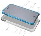
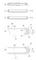
도 1은 일 실시 예에 따라 전자 기기가 설치된 케이스의 분해 사시도이다.
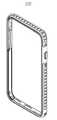
도 2는 일 실시 예에 따라 전자 기기가 설치된 케이스의 사시도이다.
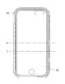
도 3은 일 실시 예에 따른 케이스의 정면도이다.
도 4는 일 실시 예에 따른 케이스의 배면도이다.
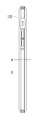
도 5는 일 실시 예에 따른 케이스의 좌측면도이다.
도 6은 일 실시 예에 따른 케이스의 우측면도 및 단면도이다.
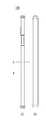
도 7은 일 실시 예에 따른 케이스의 평면도 및 단면도이다.
도 8은 일 실시 예에 따른 케이스의 저면도와 단면도 및 그 확대된 단면도이다.
도 9는 다른 일 실시 예에 따른 케이스의 정면도이다.
도 10은 또 다른 일 실시 예에 따른 전자 기기가 설치된 케이스의 사시도이다.
도 11은 또 다른 일 실시 예에 따른 전자 기기가 설치된 케이스의 다른 사시도와 그 확대된 사시도이다.
도 12는 또 다른 일 실시 예에 따른 케이스의 정면도이다.
도 13은 또 다른 일 실시 예에 따른 케이스의 배면도이다.
도 14는 또 다른 일 실시 예에 따른 케이스의 좌측면도이다.
도 15는 또 다른 일 실시 예에 따른 케이스의 우측면도 및 단면도이다.
도 16은 또 다른 일 실시 예에 따른 케이스의 평면도 및 단면도이다.
도 17은 또 다른 일 실시 예에 따른 케이스의 저면도와 단면도 및 그 확대된 단면도이다.
도 18은 다른 일 실시 예에 따른 제 1 열가소성 폴리우레탄 레이어와 제 2 열가소성 폴리우레탄 레이어 사이의 대체 가능한 결합 구조를 설명하기 위한 도면이다.
도 19는 다른 일 실시 예에 따른 제 1 열가소성 폴리우레탄 레이어와 제 2 열가소성 폴리우레탄 레이어 사이의 대체적인 다른 결합 구조를 설명하기 위한 도면이다.
도 20은 일부 실시 예에 대한 다양한 각도에서의 도면들이다.
도 21은 다양한 실시 예에 따른 동공의 구조를 설명하기 위한 도면이다.
도 22a, 도 22b, 도 22c 및 도 22d는 일부 실시 예에 따라 고정 부재를 포함하는 보호 커버를 도시한 도면이다.
도 23a 및 도 23b는 또 다른 일 실시 예에 따른 보호 커버와 삽입부의 분해 사시도 및 결합 사시도이다.1 is an exploded perspective view of a case in which an electronic device is installed according to an embodiment.
2 is a perspective view of a case in which an electronic apparatus is installed according to an embodiment.
3 is a front view of a case according to one embodiment.
4 is a rear view of a case according to one embodiment.
5 is a left side view of a case according to an embodiment.
6 is a right side view and a cross-sectional view of a case according to an embodiment.
7 is a top view and a cross-sectional view of a case according to one embodiment.
8 is a bottom view and cross-sectional view of the case according to one embodiment and an enlarged cross-sectional view thereof.
9 is a front view of a case according to another embodiment.
10 is a perspective view of a case in which an electronic apparatus according to another embodiment is installed.
11 is another perspective view and an enlarged perspective view of a case in which an electronic apparatus according to another embodiment is installed.
12 is a front view of a case according to another embodiment.
13 is a rear view of a case according to another embodiment.
14 is a left side view of a case according to another embodiment.
15 is a right side view and a cross-sectional view of a case according to another embodiment.
16 is a plan view and a cross-sectional view of a case according to another embodiment.
17 is a bottom view and cross-sectional view of the case according to yet another embodiment and its enlarged cross-sectional view.
18 is a view for explaining a substitute bonding structure between a first thermoplastic polyurethane layer and a second thermoplastic polyurethane layer according to another embodiment.
19 is a view for explaining another alternative bonding structure between the first thermoplastic polyurethane layer and the second thermoplastic polyurethane layer according to another embodiment.
20 are views at various angles for some embodiments.
21 is a view for explaining the structure of a pupil according to various embodiments.
Figures 22A, 22B, 22C and 22D are views showing a protective cover including a fixing member according to some embodiments.
23A and 23B are an exploded perspective view and a combined perspective view of a protective cover and an insertion portion according to another embodiment.
아래에서는 첨부한 도면을 참조하여 본 고안의 실시예를 상세히 설명한다. 그러나 본 고안은 여러 가지 상이한 형태로 구현될 수 있으며 여기에서 설명하는 실시예의 특정 기기, 방법, 상태 또는 파라미터 등에 한정되지 않는다. 본 명세서에서 사용되는 용어들은 실시예를 설명하기 위한 것이며 본 고안을 한정하고자 하는 것이 아니다.Hereinafter, embodiments of the present invention will be described in detail with reference to the accompanying drawings. However, the present invention may be embodied in many different forms and should not be construed as limited to the specific apparatus, method, state or parameters of the embodiments described herein. It is to be understood that the terminology used herein is for the purpose of describing particular embodiments only and is not intended to be limiting.
또한, 첨부된 청구항을 포함하는 명세서 내에서 사용되는 단수의 표현은 복수의 개념을 포함할 수 있으며, 수치에 대한 언급은 특별히 반대되는 기재가 없는 한 해당 수치를 포함한다는 것을 의미한다. 범위의 표현은 특정 값 '정도' 또는 '대략'으로부터 다른 특정 값 '정도' 또는 '대략'을 표현하는 것이다. 범위에 대한 표현은 한 특정 값으로부터 다른 특정 값까지의 다른 실시 예를 포함한다. 유사하게, 근사치로서의 값에 대한 표현은 '정도'의 표현으로 다른 실시 예를 포함할 수 있다.Furthermore, the singular < Desc / Clms Page number 3 > expressions used in the specification including the appended claims may include a plurality of concepts, and a reference to a numerical value means that the numerical value is included unless specifically stated otherwise. A representation of a range is a representation of a particular value 'about' or 'about' to another particular value 'about' or 'roughly'. Expressions for ranges include other embodiments from one particular value to another. Similarly, a representation of a value as an approximation may include other embodiments in the expression of " degree ".
도 1 내지 8은 본 발명의 일 실시 예를 도시한 것이며, 도 9는 다른 실시 예를 도시한 것이다. 도 10 내지 도 17은 또 다른 실시 예를 도시한 것이다.1 to 8 show one embodiment of the present invention, and Fig. 9 shows another embodiment. Figures 10 to 17 illustrate yet another embodiment.
도 1은 일 실시 예에 따라 전자 기기(100)가 설치된 케이스의 분해 사시도이다. 도 2 내지 도 8은 케이스(100)의 사시도, 정면도, 배면도, 좌측면도, 우측면도, 평면도와 다양한 단면도 및 확대도를 도시한 도면이다.1 is an exploded perspective view of a case in which an
전자 기기(200)용 케이스(100)는 전자 기기(200)의 측면부(210)를 덮으며, 상기 전자 기기(200)를 향해 배치되고 요홈부(23)를 형성하는 내측면(21) 및 외측면(22)을 포함하는 측벽부(20)를 구비하는 보호 커버(10); 및 상기 전자 기기(200)를 향해 배치된 내벽(31) 및 외벽(32)을 포함하며, 상기 요홈부(23)에 수용된 삽입부(30)를 포함할 수 있다. 삽입부(30)는 복수의 동공(40)이 형성된 것을 특징으로 할 수 있다. 또한, 복수의 동공(40)은 칸막이(45)에 의해서 서로 분리될 수 있다.The
내측면(21)은 외벽(32)에 인접하여 위치할 수 있다. 또한, 내벽(21) 및 외벽(32)은 도면에 도시된 바와 같이 곡선의 형태를 가질 수 있다.The
삽입부(30)의 내벽(31) 및 외벽(32)은 서로 종적으로 평행하거나 또는 대체적으로 평행하게 배치되고, 동공(40)은 내벽(31), 외벽(32) 및 칸막이(45)에 의해 형성될 수 있다. 동공(40)은 사다리꼴 또는 사다리꼴에 상당하는 형태의 단만을 가지고 일렬로 배치될 수 있다. 여기서, 사다리꼴 동공은 단면이 사다리꼴(부등변 사각형) 형태인 것을 의미하며, '평행하다'는 것은 직선 부분뿐만 아니라 곡선 부분에서도 내벽(31) 및 외벽(32)이 인접하지 않는 것을 의미한다.The
동공(40)의 사다리꼴 또는 사다리꼴에 상응하는 형태의 단면은 서로 대칭을 이루거나 대칭에 상응하는 형태로 배치될 수 있다. 대부분의 동공(40)은 사다리꼴 또는 사다리꼴에 상응하는 형태의 단면을 가질 수 있다. 여기서 '대부분'은 '절반 이상'을 의미할 수 있다. 도 3에서, 말단에 위치한 삼각형 단면을 가지는 동공을 제외한 전부의 동공(40)이 사다리꼴 단면을 가질 수 있다.The cross-sections of the
또는, 삽입부(30)의 내벽(31) 및 외벽(32)은 종적으로 평행하고 동공(40)은 내벽(31), 외벽(32) 및 칸막이(41)에 의해 형성되며, 동공(40)은 삼각형 또는 삼각형에 상응하는 형태의 단면을 가지고 하나의 열로 배치될 수 있다. 동공(40)의 삼각형 또는 삼각형에 상응하는 형태의 동공(40)은 대칭을 이루거나 대칭에 상응하는 형태로 배치될 수 있다. 또한, 도 9에 도시된 바와 같이 대부분의 동공(40)이 삼각형 또는 삼각형에 상응하는 형태의 단면을 가지거나, 또는 도 9에 도시된 바와 같이 거의 모든 동공이 삼각형 또는 삼각형에 상응하는 형태의 단면을 가질 수 있다.Alternatively, the
또는, 삽입부(30)의 내벽(31) 및 외벽(32)은 종적으로 평행하고 동공(40)은 내벽(31), 외벽(32) 및 칸막이(41)에 의해 형성되며, 동공(40)은 직사각형 또는 직사각형에 상응하는 형태의 단면을 가지고 하나의 열로 배치될 수 있다. 직사각형 또는 직사각형에 상응하는 단면을 가지는 동공(40)은 도 21에 도시된 바와 같이 대칭을 이루거나 대칭에 상응하는 형태로 배치될 수 있다. 대부분의 동공(40)이 직사각형 또는 직사각형에 상응하는 단면을 가질 수 있다.Alternatively, the
실시 예에 따라서, 동공(40)은 여러 형태의 단면들의 조합으로 형성될 수도 있다. 예를 들어, 복수의 동공(40)은 각각 사다리꼴 동공, 삼각형 동공 및 직사각형 동공의 조합으로 형성될 수도 있다.Depending on the embodiment, the
또 다른 실시 예에 따르면, 도 21에 도시된 바와 같이 삽입부(30)는 상부 벽(33) 및 하부 벽(34)을 더 포함할 수도 있다. 삽입부(30)는 내벽(31), 외벽(32), 상부 벽(33) 및 하부 벽(34)에 의해 튜브 형태를 가질 수도 있다. 상부 벽(33) 및 하부 벽(34)은 실시 예에 따라 제외될 수도 있다. 또한, 도 21에서는 삽입부(30)의 단면이 사각형인 것으로 도시되었으나, 삽입부(30)의 단면은 실시 예에 따라서 타원형이나 다른 다각형 등으로 다양하게 변경될 수 있다.According to another embodiment, the
삽입부(30)는 도 1 또는 도 4에 도시된 바와 같이 전자 기기(200)의 측면부(210)의 상당 부분을 덮도록 형성될 수 있다. 보호 커버(10)의 측벽부(20)는 전자 기기(200) 방향으로 압력이 가해지도록 전자 기기(20)의 측면부(210) 주변을 연속적으로 감싸도록 형성될 수 있다. 이러한 구조를 통하여 전자 기기(200)는 측벽부(20) 내에서 안전하게 보호될 수 있다.The
삽입부(30)는 돌출부(70)를 구비하고, 보호 커버(10)의 측벽부(20)는 돌출부(70)를 수용하거나 돌출부(70)와 결합될 수 있는 결합 오목부(75)를 포함할 수 있다.The
또는, 보호 커버(10)의 측벽부(20)가 돌출부(70)를 구비하고, 삽입부(30)가 돌출부(70)를 수용하거나 돌출부(70)와 결합될 수 있는 결합 오목부(75)를 포함할 수도 있다.Alternatively, the
바람직하게는, 넷, 여섯 또는 여덟 개의 돌출부(70)와 결합 오목부(75)의 결합에 의해 삽입부(30)가 보호 커버(10) 내에서 움직이지 않도록 고정될 수 있다. 예를 들어, 도 4에 도시된 바와 같이 삽입부(30)가 보호 커버(10) 내에 고정될 수 있다.Preferably, the
또는, 삽입부(30)는 접착제, 본드, 풀, 테이프, 양면 접착제 등의 접착 부재에 의해 보호 커버(10)의 측벽부(20)에 고정적으로 부착될 수도 있다.Alternatively, the
보호 커버(10)의 측벽부(20)는 열가소성 폴리우레탄(Thermoplastic Poly-Urethane; TPU)으로 구성될 수 있다. 삽입부(30)는 열가소성 폴리우레탄(Thermoplastic Poly-Urethane; TPU)으로 구성될 수 있다. 또는 삽입부(30)는 열가소성 탄성중합체(ThermoPlastic Elastomers; TPE), 실리콘 또는 다른 연성의 유연한 재질로 구성될 수도 있다.The
삽입부(30) 및 보호 커버(10)의 측벽부(20)는 별도로 제조되고 결합 구조에 의해 분리 가능하게 결합될 수 있다. 또는 삽입부(30) 및 보호 커버(10)의 측벽부(20)는 이중 사출 성형에 의해 제조될 수도 있다.The
보호 커버(10)의 측벽부(20)는 투명하거나, 반투명하거나 또는 불투명할 수 있다. 바람직하게는, 보호 커버(10)의 측벽부(20)는 백색 또는 유사 백색(투명 또는 반투명)일 수 있다. 삽입부(30)는 측벽부(20)를 관통하여 볼 수 있는 선명한 색상을 가질 수도 있다.The
보호 커버(10)는 전자 기기(200)의 후면부(220)의 상당 부분을 덮는 백 플레이트(50)를 더 포함할 수 있으며, 보호 커버(10)는 전자 기기(200)의 전면부(230)의 상당 부분은 덮지 않도록 구성될 수 있다. 전면부(230)는 주로 화면이 배치된다.The
백 플레이트(50)는 측벽부(20)와 백 플레이트(50)가 일체로 형성되도록 열가소성 폴리우레탄으로 구성될 수 있다. 백 플레이트(50)는 투명하거나, 반투명하거나 또는 불투명한 플라스틱으로 구성될 수도 있다. 보호 커버(10)는 이중 사출 성형을 통해서 제조될 수 있다. 백 플레이트(50)는 제 1 사출 성형으로 제조되고, 측벽부(50)는 백 플레이트(50)의 가장자리 상에 제 2 사출 성형으로 제조될 수 있다.The
또는 백 플레이트(50)는 플레이트를 절단하는 방식을 통해 제조되고, 백 플레이트(50)의 가장자리 상에 측벽부(20)가 사출 성형을 통해서 제조될 수 있다. 백 플레이트(50)는 폴리카보네이트(Polycarbonate) 또는 아크릴(Acryl)로 구성될 수 있다.Or the
도 10 내지 도 17은 또 다른 실시 예를 도시한 것이다. 도 10은 전자 기기(200)가 설치된 케이스(100)의 사시도를 도시한 것이다. 도 11 내지 도 17은 정면도, 배면도, 좌측면도, 우측면도, 평면도와 다양한 단면도 및 확대도를 도시한 도면이다.Figures 10 to 17 illustrate yet another embodiment. 10 shows a perspective view of a
전자 기기(200)용 케이스(100)는 전자 기기(200)의 측면부(210)를 덮으며, 상기 전자 기기(200)를 향해 배치되고 요홈부(23)를 형성하는 내측면(21) 및 외측면(22)을 포함하는 측벽부(20)를 구비하는 보호 커버(10); 및 상기 전자 기기(200)를 향해 배치된 내측면(31) 및 외측면(32)을 포함하며, 상기 요홈부(23)에 수용된 삽입부(30)를 포함할 수 있다. 또한, 상기 삽입부(30)의 상기 외측면(32)은 종적으로 배열된 복수의 오목부(60)를 포함할 수 있다. 또한, 복수의 오목부(60)는 복수의 칸막이(65)에 의해 서로 구분되고, 측벽부(20) 및 삽입부(30)의 외측면(32) 사이에 공간을 형성할 수 있다. 측벽부(20) 및 삽입부(30)의 외측면(32) 사이에 형성된 공간은 충격을 흡수하는 에어 쿠션의 역할을 할 수 있다.The
측벽부(20)의 내측면(21)은 삽입부(30)의 외측면(32)과 인접하게 배치될 수 있다. 또한, 측벽부(20)의 내측면(21)과 삽입부(30)의 외측면(32)은 도면에 도시된 바와 같이 곡선의 형태를 가질 수 있다. 그러나, 오목부(60)에 의해 형성된 공간은 측벽부(20)의 내측면(21)과 삽입부(30)의 외측면(32) 사이의 간격이며, 해당 공간들이 있는 부분에서는 측벽부(20)의 내측면(21)과 삽입부(30)의 외측면(32)은 인접하지 않는다. 오목부(60)에 의해 형성된 공간은 충격을 흡수하는 에어 쿠션의 역할을 할 수 있다.The
도 11에 도시된 바와 같이, 오목부(60)는 칸막이(65)에 의해 구분되는 대칭적인 오목부(60)의 열을 형성하는 직사각형 베이스(61)와 두 아치 형태의 측면(62, 63)을 포함할 수 있다. 다만, 이에 한정되지 아니한다.11, the
삽입부(60)는 전자 기기(200)의 측면부(210)의 상당 부분을 덮을 수 있다. 보호 커버(10)의 측벽부(20)는 전자 기기(200) 방향으로 압력이 가해지도록 전자 기기(20)의 측면부(210) 주변을 연속적으로 감싸도록 형성될 수 있다.The inserting
삽입부(30)는 돌출부(70)를 구비하고, 보호 커버(10)의 측벽부(20)는 돌출부(70)를 수용하거나 돌출부(70)와 결합될 수 있는 결합 동공(75)을 포함할 수 있다. 바람직하게는, 넷, 여섯 또는 여덟 개의 돌출부(70)와 결합 동공(75)의 결합에 의해 삽입부(30)가 보호 커버(10) 내에서 움직이지 않도록 고정될 수 있다.The
또는, 삽입부(30)는 돌출부(70)를 구비하고, 보호 커버(10)의 측벽부(20)는 돌출부(70)를 수용하거나 돌출부(70)와 결합될 수 있는 결합 오목부(75)를 포함할 수 있다. 결합 동공 또는 결합 오목부의 결합이 함께 이용될 수도 있다.Alternatively, the
또는, 보호 커버(10)의 측벽부(20)는 돌출부(70)를 구비하고, 삽입부(30)는 돌출부(70)를 수용하거나 돌출부(70)와 결합될 수 있는 결합 오목부(75)를 포함할 수 있다.Alternatively, the
바람직하게는, 삽입부(30)는 제거 가능하거나 또는 분리 가능하도록 보호 커버(10)의 측벽부(20) 내에 수용될 수 있다.Preferably, the
삽입부(30)는 접착제, 본드, 풀, 테이프, 양면 접착제 등의 접착 부재에 의해 보호 커버(10)의 측벽부(20)에 고정적으로 부착될 수도 있다.The
보호 커버(10)의 측벽부(20)는 열가소성 폴리우레탄(Thermoplastic Poly-Urethane; TPU)으로 구성될 수 있다. 삽입부(30)는 열가소성 폴리우레탄(Thermoplastic Poly-Urethane; TPU)으로 구성될 수 있다. 또는 삽입부(30)는 열가소성 탄성중합체(ThermoPlastic Elastomers; TPE), 실리콘 또는 다른 연성의 유연한 재질로 구성될 수도 있다.The
삽입부(30) 및 보호 커버(10)의 측벽부(20)는 별도로 제조되거나, 또는 삽입부(30)와 보호 커버(10)의 측벽부(20)는 이중 사출 성형에 의해 제조될 수 있다.The
보호 커버(10)의 측벽부(20)는 투명하거나, 반투명하거나 또는 불투명할 수 있다. 바람직하게는, 보호 커버(10)의 측벽부(20)는 백색 또는 유사 백색(투명 또는 반투명)일 수 있다. 삽입부(30)는 측벽부(20)를 관통하여 볼 수 있는 선명한 색상을 가질 수도 있다.The
보호 커버(10)는 전자 기기(200)의 후면부(220)의 상당 부분을 덮는 백 플레이트(50)를 더 포함할 수 있으며, 보호 커버(10)는 전자 기기(200)의 전면부(230)의 상당 부분은 덮지 않도록 구성될 수 있다.The
백 플레이트(50) 및 측벽부(20)는 열가소성 폴리우레탄으로 형성될 수 있다. 또는, 백 플레이트(50)는 투명하거나, 반투명하거나 또는 불투명한 플라스틱으로 구성되고, 보호 커버(10)는 이중 사출 성형을 통해서 제조될 수 있다. 백 플레이트(50)는 제 1 사출 성형으로 제조되고, 측벽부(50)는 백 플레이트(50)의 가장자리 상에 제 2 사출 성형으로 제조될 수 있다.Back
또는, 백 플레이트(50)는 플레이트를 절단하는 방식을 통해 제조되고, 백 플레이트(50)의 가장자리 상에 측벽부(20)가 사출 성형을 통해서 제조될 수 있다. 백 플레이트(50)는 폴리카보네이트(Polycarbonate) 또는 아크릴(Acryl)로 구성될 수 있다.Alternatively, the
도 22a, 22b, 22c 및 22d는 일부 실시 예에 따라 고정 부재(91)를 포함하는 보호 커버를 도시한 도면이다. 도 22b 및 도 22d는 각각 도 22a 및 도 22c를 확대한 확대도이다.22A, 22B, 22C, and 22D are views showing a protective cover including a fixing
보호 커버(10)는 보호 커버(10)의 내측면(21)의 양 가장자리에 형성된 한 쌍의 고정 부재(91)를 더 포함할 수 있다. 고정 부재(91)는 삽입부(30)가 요홈부(23) 내로 삽입될 수 있도록 구성되고, 삽입부(30)가 요홈부(23)로부터 쉽게 이탈되지 않도록 구성된 것을 특징으로 할 수 있다.The
바람직하게는, 고정 부재(91)는 내측면(21)의 가장자리 상에 종적으로 길게 형성된 돌출부이거나 또는 리브(rib)일 수 있다. 또한, 삽입부(30)는 고정 부재(91)를 수용할 수 있는 수용부(오목한 부분, 도시되지 않음)를 구비할 수 있다. 고정 부재(91)와 수용부 사이의 결합이 삽입부(30)가 요홈부(23)로부터 쉽게 이탈되는 것을 방지할 수 있다.Preferably, the
내측면(21)은 외관상 곡면으로 이루어지고 고정 부재(91)는 비스듬한 모양으로 형성될 수 있다. 이러한 형태로 인하여 삽입부(30)는 고정 부재(91)가 변형됨으로써 요홈부(23) 내로 삽입될 수 있다. 삽입부(30)가 요홈부(23) 내에 고정되면, 고정 부재(91)로 인하여 삽입부(30)가 요홈부(23)로부터 쉽게 분리되지 않는다.The
고정 부재(91)는 바람직하게는 측벽부(20)와 함께 제조되고, 열가소성 폴레우레탄으로 구성될 수 있다. 도 22a 또는 도 22c에 도시된 도시된 바와 같이, 내측면(21)의 가장자리에 여러 쌍의 고정 부재(91)가 배치될 수 있다. 또한, 삽입부(30) 상에서 여러 쌍의 고정 부재(91)의 위치에 상응하는 위치에 여러 쌍의 수용부가 구비될 수 있다.The fixing
도 23a 및 도 23b는 또 다른 일 실시 예에 따른 보호 커버와 삽입부의 분해 사시도 및 결합 사시도이다.23A and 23B are an exploded perspective view and an assembled perspective view of a protective cover and an insertion portion according to another embodiment.
전자 기기(200)용 케이스(100)는 전자 기기(200)의 측면부(210)를 덮으며, 상기 전자 기기(200)를 향해 배치되고 요홈부(23)를 형성하는 내측면(21) 및 외측면(22)을 포함하는 측벽부(20)를 구비하는 보호 커버(10); 및 상기 요홈부(23)에 수용되는 삽입부(30)를 포함할 수 있다.The
보호 커버(10)는 보호 커버(10)의 내측면(21)의 양 가장자리에 형성된 한 쌍의 고정 부재(91)를 더 포함할 수 있다. 고정 부재(91)는 삽입부(30)가 요홈부(23) 내로 삽입될 수 있도록 구성되고, 삽입부(30)가 요홈부(23)로부터 쉽게 이탈되지 않도록 구성된 것을 특징으로 할 수 있다.The
고정 부재(91)는 보호 커버(100)의 외측면(22) 방향으로 비스듬하게 기울어졌으며, 종적으로 길게 형성된 돌출부일 수 있다. 또한, 삽입부(30)는 고정 부재(91)를 수용할 수 있는 한 쌍의 수용부(오목한 부분)를 구비할 수 있다.The fixing
삽입부(30)는 길이 방향으로 긴 형태를 가지며, 내벽(31) 및 외벽(32)을 포함할 수 있다. 내벽(31)은 전자 기기(200) 방향으로 배치된다.The
삽입부(30)는 삽입부(30)의 양 말단에 형성된 한 쌍의 결합 돌출부(92)를 더 포함할 수 있으며, 보호 커버(10)의 내측면(21) 상에 한 쌍의 결합 요홈(93)이 형성될 수 있고, 한 쌍의 결합 요홈(93)은 삽입부(30)가 요홈부(23) 내에 안정적으로 유지되도록 하기 위해 한 쌍의 결합 돌출부(92)를 각각 수용할 수 있다.The
또는, 삽입부(30)는 삽입부(30)의 양 말단에 형성된 한 쌍의 결합 요홈(93)을 더 포함할 수 있으며, 보호 커버(10)의 내측면(21) 상에 한 쌍의 결합 돌출부(92)가 형성될 수 있고, 한 쌍의 결합 요홈(93)은 삽입부(30)가 요홈부(23) 내에 안정적으로 유지되도록 하기 위해 한 쌍의 결합 돌출부(92)를 각각 수용할 수 있다.Alternatively, the
본 발명이 다른 실시 예들을 참조로 하여 기술되었으나, 본 고안이 속하는 기술분야의 통상의 지식을 가진 자에 의하여 본 고안의 기술적 사상이나 필수적인 특징을 변경하지 않고서 형태, 세부사항, 구성요소 및 동작 등에 대하여 변경을 가할 수 있다. 그러므로 이상에서 기술한 실시예들은 모든 면에서 예시적인 것이며 한정적이 아닌 것으로 이해해야만 한다. 예를 들어, 단일형으로 설명되어 있는 각 구성 요소는 분산되어 실시될 수도 있으며, 마찬가지로 분산된 것으로 설명되어 있는 구성 요소들도 결합된 형태로 실시될 수 있다.Although the present invention has been described with reference to exemplary embodiments, it will be understood by those skilled in the art that various changes in form and detail may be made therein without departing from the spirit and scope of the invention, Can be changed. It is therefore to be understood that the above-described embodiments are illustrative in all aspects and not restrictive. For example, each component described as a single entity may be distributed and implemented, and components described as being distributed may also be implemented in a combined form.
본 고안의 범위는 상기 상세한 설명보다는 후술하는 특허청구범위에 의하여 나타내어지며, 특허청구범위의 의미 및 범위 그리고 그 균등 개념으로부터 도출되는 모든 변경 또는 변형된 형태가 본 고안의 범위에 포함되는 것으로 해석되어야 한다.The scope of the present invention is defined by the appended claims rather than the foregoing description and all changes or modifications derived from the meaning and scope of the claims and equivalents thereof are to be construed as being included within the scope of the present invention do.
100: 케이스
200: 전자 기기
210: 전자 기기의 측면부
220: 전자 기기의 후면부
230: 전자 기기의 전면부
10: 보호 커버
20: 측벽부
21: 내측면
22: 외측면
23: 요홈부
30: 삽입부
31: 내벽
32: 외벽
33: 상부 벽
34: 하부 벽
40: 동공
50: 백 플레이트
60: 오목부
61: 직사각형 베이스
62, 63 : 아치형 측면
65: 칸막이
70: 돌출부
75: 결합 동공
91: 고정 부재
92: 결합 돌출부
93: 결합 요홈100: Case
200: Electronic device
210: side portion of the electronic device
220: Rear part of the electronic device
230: Front portion of the electronic device
10: Protective cover
20:
21: My side
22: Outer side
23:
30:
31: inner wall
32: outer wall
33: upper wall
34: Lower wall
40: pupil
50: back plate
60:
61: rectangular base
62, 63: arcuate side
65: partition
70:
75: Associated pupil
91: Fixing member
92: engaging projection
93: Coupling groove
Claims (56)
Translated fromKorean상기 전자 기기(200)를 향해 배치된 내벽(31) 및 외벽(32)을 포함하며, 상기 요홈부(23)에 수용된 삽입부(30)를 포함하되,
상기 삽입부(30)는 동공(40)이 형성되고, 상기 삽입부(30)가 상기 내벽(31) 및 외벽(32)과 함께 관 형태를 가지도록 하는 상부 벽(33) 및 하부 벽(34)과, 상기 삽입부(30)의 양 말단에 형성된 결합 돌출부(92) 및 결합 요홈(93) 중 어느 하나를 포함하며, 상기 삽입부(30)의 상기 외벽(32)은 복수의 오목부(60)를 포함하고,
상기 보호 커버(10)는 상기 내측면(21)에 형성되되, 상기 삽입부(30)의 양 말단에 형성된, 상기 결합 돌출부(92)를 수용할 수 있는 크기로 형성되는 상기 결합 요홈(93) 또는 상기 결합 요홈(93)을 수용할 수 있는 크기로 형성되는 상기 결합 돌출부(92) 중 어느 하나를 더 포함하며,
상기 오목부(60)는 상기 측벽부(20)의 상기 내측면(21) 및 상기 삽입부(30)의 외측면(32) 사이의 공간에 형성된 칸막이(65)에 의해 구분되고, 상기 측벽부(20) 및 상기 삽입부(30)의 상기 외측면(32) 사이에 공간을 형성하며, 직사각형 베이스(61) 및 두 아치 형태의 측면(62, 63)을 구비하고, 상기 칸막이(65)에 의해 구분된 다른 대칭적인 상기 오목부(60)와 하나의 열을 형성하는 것을 특징으로 하는, 전자 기기(200)용 케이스(100).
A side wall portion 20 (including an inner side surface 21 and an outer side surface 22) covering the side surface portion 210 of the electronic device 200 and disposed toward the electronic device 200 and forming the recessed portion 23 (10); And
And an insertion part (30) including an inner wall (31) and an outer wall (32) arranged toward the electronic device (200) and accommodated in the recessed part (23)
The insertion section 30 includes a top wall 33 and a bottom wall 34 which form a cavity 40 and allow the insertion section 30 to have a tubular shape with the inner and outer walls 31 and 32 And an engaging protrusion 92 and an engaging recess 93 formed at both ends of the inserting portion 30. The outer wall 32 of the inserting portion 30 includes a plurality of recesses 60,
The protective cover 10 is formed on the inner side surface 21 and is formed at both ends of the insertion portion 30. The protective cover 10 has the engagement groove 93 formed to have a size capable of accommodating the engagement projection 92, Or the engaging projection (92) formed to have a size capable of receiving the engaging recess (93)
The concave portion 60 is divided by a partition 65 formed in a space between the inner side surface 21 of the side wall portion 20 and the outer side surface 32 of the insertion portion 30, (62, 63), forming a space between the outer surface (20) of the insert (30) and the outer surface (32) of the insert (30) and having a rectangular base (61) (60) and the other symmetrical recesses (60) separated by the first and second recesses (60).
상기 보호 커버(10)는 상기 보호 커버(10)의 내측면(21)의 양 가장자리에 형성된 한 쌍의 고정 부재(91)를 포함하고,
상기 고정 부재(91)는 상기 삽입부(30)가 상기 요홈부(23) 내에 삽입 가능하되 상기 삽입부(30)가 상기 요홈부(23)로부터 이탈되지 않게 고정되도록 형성된 것을 특징으로 하는, 전자 기기(200)용 케이스(100).
The method according to claim 1,
The protective cover 10 includes a pair of fixing members 91 formed at both edges of the inner surface 21 of the protective cover 10,
Characterized in that the fixing member (91) is formed such that the insertion portion (30) is insertable into the recessed portion (23), and the insertion portion (30) is fixed so as not to be separated from the recessed portion A case (100) for a device (200).
상기 고정 부재(91)는 상기 보호 커버(10)의 상기 외측면(22)에 대하여 비스듬하게 형성된 돌출부인 것을 특징으로 하는, 전자 기기(200)용 케이스(100).
3. The method of claim 2,
The case (100) for an electronic device (200) according to claim 1, wherein the fixing member (91) is a protrusion formed obliquely with respect to the outer surface (22) of the protective cover (10).
상기 삽입부(30)는 상기 고정 부재(91)를 수용할 수 있는 한 쌍의 홈을 더 구비하는 것을 특징으로 하는, 전자 기기(200)용 케이스(100).
3. The method of claim 2,
The case (100) for an electronic device (200) according to any one of the preceding claims, wherein the insertion portion (30) further comprises a pair of grooves capable of receiving the fixing member (91).
상기 동공(40)은 칸막이(45)에 의해 구분된 것을 특징으로 하는, 전자 기기(200)용 케이스(100).
The method according to claim 1,
The case (100) for an electronic device (200) according to claim 1, characterized in that the pupil (40) is divided by a partition (45).
상기 삽입부(30)의 상기 내벽(31) 및 상기 외벽(32)은 서로 평행하게 배치되고, 상기 동공(40)은 상기 내벽(31), 상기 외벽(32) 및 칸막이(45)에 의해 형성되며,
상기 동공(40)은 각각 사다리꼴 단면의 형태를 가지며, 상기 동공(40)의 사다리꼴 단면은 하나의 열로 배치된 것을 특징으로 하는, 전자 기기(200)용 케이스(100).
6. The method of claim 5,
The inner wall 31 and the outer wall 32 of the insertion portion 30 are arranged parallel to each other and the pupil 40 is formed by the inner wall 31, the outer wall 32 and the partition 45 And,
The case (100) for an electronic device (200) according to any one of the preceding claims, wherein the pupil (40) has a trapezoidal cross section and the trapezoidal cross section of the pupil (40) is arranged in a single row.
상기 동공(40)의 상기 사다리꼴 단면은 인접한 다른 동공의 사다리꼴 단면에 대하여 대칭적인 형상인 것을 특징으로 하는, 전자 기기(200)용 케이스(100).
The method according to claim 6,
Wherein the trapezoidal cross section of the pupil (40) is symmetrical with respect to a trapezoidal cross section of another adjacent pupil.
상기 삽입부(30)의 상기 내벽(31) 및 상기 외벽(32)은 서로 평행하게 배치되며, 상기 동공(40)은 내벽(31) 및/또는 외벽(32)과 상기 칸막이(45)에 의해 형성되고,
상기 동공(40)은 삼각형 단면의 형태를 가지며, 상기 동공(40)의 삼각형 단면들은 하나의 열로 배치된 것을 특징으로 하는, 전자 기기(200)용 케이스(100).
6. The method of claim 5,
The inner wall 31 and the outer wall 32 of the insertion part 30 are arranged parallel to each other and the pupil 40 is formed by the inner and outer walls 31 and 32 and the partition 45 Formed,
Wherein the pupil (40) is in the form of a triangular cross-section, and the triangular cross-sections of the pupil (40) are arranged in a single row.
상기 동공(40)의 상기 삼각형 단면은 인접한 다른 동공의 삼각형 단면에 대하여 대칭적인 형상인 것을 특징으로 하는, 전자 기기(200)용 케이스(100).
9. The method of claim 8,
Characterized in that the triangular cross section of the pupil (40) is symmetrical with respect to a triangular cross section of another adjacent pupil.
상기 삽입부(30)의 상기 내벽(31) 및 상기 외벽(32)은 서로 평행하게 배치되고, 상기 동공(40)은 상기 내벽(31), 상기 외벽(32) 및 칸막이(45)에 의해 형성되며,
상기 동공(40)은 각각 직사각형 단면의 형태를 가지며, 상기 동공(40)의 사각형 단면은 하나의 열로 배치된 것을 특징으로 하는, 전자 기기(200)용 케이스(100).
6. The method of claim 5,
The inner wall 31 and the outer wall 32 of the insertion portion 30 are arranged parallel to each other and the pupil 40 is formed by the inner wall 31, the outer wall 32 and the partition 45 And,
The case (100) for an electronic device (200) according to any one of the preceding claims, wherein the pupil (40) has a rectangular cross section and the rectangular cross section of the pupil (40) is arranged in a single row.
상기 동공(40)의 상기 사각형 단면은 인접한 다른 동공의 사각형 단면에 대하여 대칭적인 형상인 것을 특징으로 하는, 전자 기기(200)용 케이스(100).
11. The method of claim 10,
Wherein the rectangular cross section of the pupil (40) is symmetrical with respect to a rectangular cross section of another adjacent pupil.
상기 삽입부(30)는, 전자 기기(200)의 측면부(210)를 덮도록 배치되는 것을 특징으로 하는, 전자 기기(200)용 케이스(100).
The method according to claim 1,
A case (100) for an electronic device (200), characterized in that the insertion portion (30) is arranged to cover a side surface portion (210) of the electronic device (200).
상기 보호 커버(10)의 상기 측벽부(20)는 상기 전자 기기(200) 방향으로 압력이 가해지도록 상기 전자 기기(200)의 측면부(210)를 감싸는 것을 특징으로 하는, 전자 기기(200)용 케이스(100).
14. The method of claim 13,
Characterized in that the side wall part (20) of the protective cover (10) surrounds the side surface part (210) of the electronic device (200) so as to apply pressure in the direction of the electronic device Case 100.
상기 삽입부(30)는 돌출부(70)를 구비하고,
상기 보호 커버(10)의 측벽부(20)는 상기 돌출부(70)를 수용하거나 상기 돌출부(70)와 결합되는 결합 오목부(75)를 포함하는, 전자 기기(200)용 케이스(100).
The method according to claim 1,
The insertion portion 30 has a protrusion 70,
Wherein the side wall portion (20) of the protective cover (10) includes a coupling recess (75) for receiving the projection (70) or engaging the projection (70).
상기 보호 커버(10)의 상기 측벽부(20)는 돌출부(70)를 구비하고,
상기 삽입부(30)는 상기 돌출부(70)를 수용하거나 상기 돌출부(70)와 결합되는 결합 오목부(75)를 포함하는, 전자 기기(200)용 케이스(100).
The method according to claim 1,
The side wall portion 20 of the protective cover 10 has a protrusion 70,
The insertion portion (30) includes a coupling recess (75) for receiving the protrusion (70) or engaging with the protrusion (70).
상기 삽입부(30)는 보호 커버(10)의 측벽부(20)에 분리가능하도록 수용되는 것을 특징으로 하는, 전자 기기(200)용 케이스(100).
The method according to claim 1,
The case (100) for an electronic device (200) according to any one of the preceding claims, wherein the insert (30) is removably received in a side wall (20) of the protective cover (10).
상기 삽입부(30)는 부착 수단에 의해 상기 보호 커버(10)의 상기 측벽부(20)에 고정적으로 부착된 것을 특징으로 하는, 전자 기기(200)용 케이스(100).
The method according to claim 1,
Characterized in that the insert (30) is fixedly attached to the side wall (20) of the protective cover (10) by means of attachment means.
상기 보호 커버(10)의 상기 측벽부(20)는 열가소성 폴레우레탄(TPU)으로 형성된 것을 특징으로 하는, 전자 기기(200)용 케이스(100).
The method according to claim 1,
Wherein the side wall (20) of the protective cover (10) is formed of thermoplastic polyurethane (TPU).
상기 삽입부(30) 및 상기 보호 커버(10)의 측벽부(20)는 이중 사출 성형으로 제조된 것을 특징으로 하는, 전자 기기(200)용 케이스(100).
20. The method of claim 19,
A case (100) for an electronic device (200), characterized in that the insert (30) and the side wall (20) of the protective cover (10) are made by dual injection molding.
상기 보호 커버(10)의 상기 측벽부(20)는 투명하거나, 반투명하거나 또는 불투명한 것을 특징으로 하는, 전자 기기(200)용 케이스(100).
20. The method of claim 19,
Wherein the side wall portion (20) of the protective cover (10) is transparent, translucent or opaque.
상기 보호 커버(10)는 상기 전자 기기(200)의 후면부(220)를 덮는 백 플레이트(50)를 더 포함하고,
상기 보호 커버(10)는 상기 전자 기기(200)의 전면부(230)는 덮지 않는 것을 특징으로 하는, 전자 기기(200)용 케이스(100).
The method according to claim 1,
The protective cover 10 further includes a back plate 50 covering the rear portion 220 of the electronic device 200,
A case (100) for an electronic device (200), characterized in that the protective cover (10) does not cover the front portion (230) of the electronic device (200).
상기 백 플레이트(50)는 투명하거나, 반투명하거나 또는 불투명하고,
상기 보호 커버(10)는 이중 사출 성형으로 제조되며,
상기 백 플레이트(50)는 제 1 사출 성형으로 제조되고 상기 측벽부(20)는 상기 백 플레이트(50)의 가장자리 상에 제 2 사출 성형으로 제조된 것을 특징으로 하는, 전자 기기(200)용 케이스(100).
23. The method of claim 22,
The back plate 50 may be transparent, translucent or opaque,
The protective cover 10 is made by double injection molding,
Characterized in that the back plate (50) is made by a first injection molding and the side wall part (20) is made by a second injection molding on the edge of the back plate (50) (100).
상기 백 플레이트(50)는 플레이트를 절단하여 제조되고, 상기 측벽부(20)는 상기 백 플레이트(50)의 가장자리 상에 사출 성형되어 제조된 것을 특징으로 하는, 전자 기기(200)용 케이스(100).
23. The method of claim 22,
Wherein the back plate 50 is manufactured by cutting a plate and the side wall portion 20 is manufactured by injection molding on the edge of the back plate 50. [ ).
Applications Claiming Priority (6)
| Application Number | Priority Date | Filing Date | Title |
|---|---|---|---|
| US201562206787P | 2015-08-18 | 2015-08-18 | |
| US62/206,787 | 2015-08-18 | ||
| US201562210416P | 2015-08-26 | 2015-08-26 | |
| US62/210,416 | 2015-08-26 | ||
| US201562218283P | 2015-09-14 | 2015-09-14 | |
| US62/218,283 | 2015-09-14 |
Publications (2)
| Publication Number | Publication Date |
|---|---|
| KR20170000734U KR20170000734U (en) | 2017-02-28 |
| KR200486692Y1true KR200486692Y1 (en) | 2018-07-19 |
Family
ID=58157758
Family Applications (1)
| Application Number | Title | Priority Date | Filing Date |
|---|---|---|---|
| KR2020150008449UActiveKR200486692Y1 (en) | 2015-08-18 | 2015-12-23 | Case Having Double Layers For Electronic Devices |
Country Status (2)
| Country | Link |
|---|---|
| US (3) | US9872546B2 (en) |
| KR (1) | KR200486692Y1 (en) |
Cited By (1)
| Publication number | Priority date | Publication date | Assignee | Title |
|---|---|---|---|---|
| KR102661747B1 (en)* | 2023-12-28 | 2024-04-26 | 고재흠 | Functional cell phone case |
Families Citing this family (25)
| Publication number | Priority date | Publication date | Assignee | Title |
|---|---|---|---|---|
| US10709220B2 (en)* | 2015-03-12 | 2020-07-14 | Griffin Technology, Llc | Protective device case |
| USD816651S1 (en) | 2016-06-16 | 2018-05-01 | Samsonite Ip Holdings S.Àr.L. | Case for an electronic device |
| US10441044B2 (en)* | 2017-05-16 | 2019-10-15 | Samsonite Ip Holdings S.Àr.L. | Case with shock-absorbing impact geometry |
| US10694825B2 (en) | 2017-09-08 | 2020-06-30 | Samsonite Ip Holdings S.Àr.L. | Tri-layer case with shock-absorbing impact geometry |
| USD889452S1 (en) | 2017-09-08 | 2020-07-07 | Samsonite Ip Holdings S.Àr.L. | Case for an electronic device |
| US10743630B2 (en) | 2017-09-08 | 2020-08-18 | Samsonite Ip Holdings S.Àr.L. | Dual-layer bumper for a case for a mobile device |
| USD889453S1 (en) | 2017-09-08 | 2020-07-07 | Samsonite Ip Holdings S.Àr.L. | Case for an electronic device |
| USD863281S1 (en)* | 2017-11-02 | 2019-10-15 | Yongguo Liu | Case for mobile phone |
| RU184878U1 (en)* | 2017-11-22 | 2018-11-13 | Александр Дмитриевич Швец | SMARTPHONE CASE |
| US10623039B2 (en)* | 2017-12-13 | 2020-04-14 | Eli Altaras | Digital device protective case method and device |
| WO2019177358A1 (en)* | 2018-03-13 | 2019-09-19 | 하인크코리아(주) | Mobile device accessory |
| KR102097528B1 (en)* | 2018-03-13 | 2020-04-06 | 하인크코리아(주) | Mobile device accessory |
| US11005515B2 (en)* | 2018-09-10 | 2021-05-11 | Apple Inc. | Transparent accessory case for an electronic device |
| USD1003883S1 (en) | 2019-01-07 | 2023-11-07 | Speculative Product Design, Llc | Wallet for mobile device |
| US11311087B2 (en) | 2019-01-07 | 2022-04-26 | Speculative Product Design, Llc | Wallet for mobile electronic device or mobile electronic device case |
| USD976582S1 (en) | 2019-01-07 | 2023-01-31 | Speculative Product Design, Llc | Wallet for mobile device |
| US11522571B2 (en) | 2019-10-28 | 2022-12-06 | Speculative Product Design, Llc | Mobile device case with bonded soft resin insert and shell |
| US10758016B1 (en) | 2019-11-22 | 2020-09-01 | WeiGang Wang | Adjustable umbrella canopy shade |
| KR20210089865A (en)* | 2020-01-09 | 2021-07-19 | 삼성전자주식회사 | Cover for electronic device |
| US11873047B2 (en) | 2020-06-05 | 2024-01-16 | Annex Products Pty Ltd | Vibration dampening device for mounting a handheld electronic device |
| USD949138S1 (en) | 2020-06-19 | 2022-04-19 | Speculative Product Design, Llc | Case for an electronic communications device |
| US11079798B1 (en)* | 2020-12-21 | 2021-08-03 | Pioneer Square Brands, Inc. | Case for portable electronic computing device |
| USD975704S1 (en)* | 2021-09-27 | 2023-01-17 | Yongguo Liu | Case for mobile phone |
| USD1066313S1 (en)* | 2021-12-16 | 2025-03-11 | Breon Gilchrist | Infinity glass screen for a smart phone |
| US12102199B1 (en)* | 2022-05-12 | 2024-10-01 | Max Interactive, Inc. | Protective cover for a laptop computer |
Citations (7)
| Publication number | Priority date | Publication date | Assignee | Title |
|---|---|---|---|---|
| KR101122400B1 (en)* | 2011-08-01 | 2012-03-09 | 이성복 | Protective case for protecting mobile terminal including metallic plate with locking structure and manufacturing method thereof |
| KR20120081893A (en)* | 2011-01-12 | 2012-07-20 | 김중견 | Interchangeable bands are combined rubber case |
| KR101202985B1 (en)* | 2012-06-20 | 2012-11-21 | 주식회사 슈피겐에스지피 | Protective case formed by two bodies for portable electronic device |
| JP2014017395A (en)* | 2012-07-10 | 2014-01-30 | Nec Saitama Ltd | Accessory member for electronic apparatus and electronic apparatus |
| KR20140036096A (en)* | 2012-09-14 | 2014-03-25 | 조영재 | Smart phone case with shock dispersion function |
| JP3194569U (en)* | 2014-07-25 | 2014-11-27 | 鴻海精密工業股▲ふん▼有限公司 | Protective cover |
| KR20150053961A (en)* | 2012-09-07 | 2015-05-19 | 지-폼, 엘엘씨 | Protective case and methods of making |
Family Cites Families (38)
| Publication number | Priority date | Publication date | Assignee | Title |
|---|---|---|---|---|
| US5819942A (en)* | 1994-04-19 | 1998-10-13 | Outrigger, Inc. | Safety air cushion for a computer |
| KR20060123442A (en)* | 2004-01-07 | 2006-12-01 | 다우 글로벌 테크놀로지스 인크. | How to Maintain Shock Absorbing Inserts, Protective Cases, and Shock Absorbing Inserts |
| US7448495B2 (en)* | 2006-02-24 | 2008-11-11 | Bbs Licensing, Inc. | Impact resistant cushion for electronic equipment with diagonal corner support and carrying cases including the same |
| EP2020881A1 (en)* | 2006-05-09 | 2009-02-11 | Ceri Freeman | Carry cases and bags |
| US8245842B2 (en)* | 2008-06-27 | 2012-08-21 | Switcheasy Limited | Protective case having a hybrid structure for portable handheld electronic devices |
| WO2010078321A1 (en) | 2008-12-29 | 2010-07-08 | Otter Products, Llc | Protective cushion cover for an electronic device |
| US9281858B2 (en) | 2014-01-03 | 2016-03-08 | Incipio, Llc | Co-molded multi-layered protective case for mobile device |
| WO2011053740A1 (en) | 2009-10-28 | 2011-05-05 | Belkin International, Inc. | Portable multi-media communication device protective carrier and method of manufacture therefor |
| US9025317B2 (en)* | 2010-03-17 | 2015-05-05 | Otter Products, Llc | Multi-material protective case for sliding/articulating/rotating handheld electronic devices |
| US8655422B2 (en) | 2010-06-04 | 2014-02-18 | Apple Inc. | Ring-shaped cover for portable electronic device |
| KR100988204B1 (en)* | 2010-07-26 | 2010-10-18 | 에스지피코리아 (주) | Case for bar type portable electronic device |
| KR101793313B1 (en)* | 2010-10-12 | 2017-11-02 | 트리프로그 디벨롭먼츠, 인크. | Housing for encasing an electronic device |
| US20120217257A1 (en)* | 2011-02-25 | 2012-08-30 | Shao-Chieh Ting | Sleeve structure for a hand-held electronic device |
| JP3168104U (en)* | 2011-03-11 | 2011-06-02 | 勉 金谷 | Case for portable electronic devices |
| US20120305422A1 (en) | 2011-06-01 | 2012-12-06 | Scosche Industries, Inc. | Portable device protector case |
| CN105843331B (en)* | 2011-06-13 | 2019-06-14 | 树蛙开发公司 | Case to protect tablet |
| US20130235323A1 (en) | 2011-09-09 | 2013-09-12 | Gregory Allen Sotzing | Electrochromic devices prepared from the in situ formation of conjugated polymers |
| US20130098788A1 (en)* | 2011-10-19 | 2013-04-25 | Patrick McCarville | Cell Phone Case |
| WO2013106375A1 (en) | 2012-01-09 | 2013-07-18 | Case-Mate, Inc. | Protective case for portable electronic devices |
| US8770402B2 (en)* | 2012-01-26 | 2014-07-08 | Iceberg Commerce Inc. | Waterproof protective case for a mobile device |
| US9072353B2 (en)* | 2012-06-05 | 2015-07-07 | Incipio Technologies, Inc. | Active suspension case for a mobile device |
| US20140138265A1 (en)* | 2012-10-02 | 2014-05-22 | Hendra Bong | Protective Cases for Mobile Devices |
| US8439191B1 (en)* | 2012-10-19 | 2013-05-14 | Valor Communication, Inc. | Cell phone protector case having the combination of an interior soft silicone shell and a hard exterior shell with aligned retaining members |
| US8706176B1 (en)* | 2012-12-05 | 2014-04-22 | Valor Communication, Inc. | Cell phone protector case having the combination of a soft exterior shell and an interior hard shell |
| US9155367B2 (en) | 2013-03-14 | 2015-10-13 | Incipio Technologies, Inc. | Biometric and proximity sensor compatible protective case for mobile device |
| US9161597B2 (en)* | 2013-09-12 | 2015-10-20 | Otter Products, Llc | Protective case with internal suspension system |
| US9274554B2 (en) | 2013-09-13 | 2016-03-01 | Chih-Juh Wong | Protective case for electronic equipment |
| US9027746B2 (en) | 2013-09-18 | 2015-05-12 | Daniel R. Smith | Case wallet for portable handheld electronic device |
| GB2522011B (en)* | 2014-01-03 | 2016-02-17 | Tech 21 Licensing Ltd | A case for a mobile device with a screen |
| USD756344S1 (en) | 2014-09-17 | 2016-05-17 | Tech 21 Licensing Limited | Mobile communications device band |
| USD754652S1 (en) | 2014-09-17 | 2016-04-26 | Tech 21 Licensing Limited | Mobile communications device cover |
| USD754651S1 (en) | 2014-09-17 | 2016-04-26 | Tech 21 Licensing Limited | Mobile communications device band |
| USD753641S1 (en) | 2014-09-17 | 2016-04-12 | Tech 21 Licensing Limited | Mobile communications device cover |
| USD756345S1 (en) | 2014-12-24 | 2016-05-17 | Tech 21 Licensing Limited | Mobile communications device cover |
| USD747708S1 (en) | 2014-12-24 | 2016-01-19 | Tech 21 Licensing Limited | Mobile communications device cover |
| USD757704S1 (en)* | 2014-12-24 | 2016-05-31 | Tech 21 Licensing Limited | Edge protector for mobile communications device |
| USD747707S1 (en) | 2014-12-24 | 2016-01-19 | Tech 21 Licensing Limited | Mobile communications device band |
| GB2533828B (en)* | 2015-05-29 | 2018-12-12 | Tech 21 Licensing Ltd | Improved radio frequency properties of a case for a communications device |
- 2015
- 2015-12-23KRKR2020150008449Upatent/KR200486692Y1/enactiveActive
- 2016
- 2016-08-18USUS15/240,939patent/US9872546B2/enactiveActive
- 2017
- 2017-12-21USUS15/851,004patent/US10426238B2/enactiveActive
- 2019
- 2019-08-19USUS16/544,449patent/US10881179B2/enactiveActive
Patent Citations (7)
| Publication number | Priority date | Publication date | Assignee | Title |
|---|---|---|---|---|
| KR20120081893A (en)* | 2011-01-12 | 2012-07-20 | 김중견 | Interchangeable bands are combined rubber case |
| KR101122400B1 (en)* | 2011-08-01 | 2012-03-09 | 이성복 | Protective case for protecting mobile terminal including metallic plate with locking structure and manufacturing method thereof |
| KR101202985B1 (en)* | 2012-06-20 | 2012-11-21 | 주식회사 슈피겐에스지피 | Protective case formed by two bodies for portable electronic device |
| JP2014017395A (en)* | 2012-07-10 | 2014-01-30 | Nec Saitama Ltd | Accessory member for electronic apparatus and electronic apparatus |
| KR20150053961A (en)* | 2012-09-07 | 2015-05-19 | 지-폼, 엘엘씨 | Protective case and methods of making |
| KR20140036096A (en)* | 2012-09-14 | 2014-03-25 | 조영재 | Smart phone case with shock dispersion function |
| JP3194569U (en)* | 2014-07-25 | 2014-11-27 | 鴻海精密工業股▲ふん▼有限公司 | Protective cover |
Non-Patent Citations (1)
| Title |
|---|
| JP03194569 UR |
Cited By (1)
| Publication number | Priority date | Publication date | Assignee | Title |
|---|---|---|---|---|
| KR102661747B1 (en)* | 2023-12-28 | 2024-04-26 | 고재흠 | Functional cell phone case |
Also Published As
| Publication number | Publication date |
|---|---|
| KR20170000734U (en) | 2017-02-28 |
| US9872546B2 (en) | 2018-01-23 |
| US20180110304A1 (en) | 2018-04-26 |
| US20170049199A1 (en) | 2017-02-23 |
| US10881179B2 (en) | 2021-01-05 |
| US20190365067A1 (en) | 2019-12-05 |
| US10426238B2 (en) | 2019-10-01 |
Similar Documents
| Publication | Publication Date | Title |
|---|---|---|
| KR200486692Y1 (en) | Case Having Double Layers For Electronic Devices | |
| US8439191B1 (en) | Cell phone protector case having the combination of an interior soft silicone shell and a hard exterior shell with aligned retaining members | |
| KR101793313B1 (en) | Housing for encasing an electronic device | |
| US8430240B2 (en) | Case for bar type mobile electronic device | |
| US8774882B2 (en) | Mobile device case with removably insertable corners | |
| US9876522B2 (en) | Protective case for mobile device | |
| US9578940B2 (en) | Protective case for an electronic device | |
| US20130292378A1 (en) | Mobile device case having integrated latch | |
| US20140077669A1 (en) | Cover for mobile terminal | |
| KR20150081213A (en) | Protecting cover | |
| KR101857754B1 (en) | Electronic device with foldable display | |
| KR101264668B1 (en) | Case for portable terminal | |
| TWM434969U (en) | Protection device for mobile communication device | |
| US20200288833A1 (en) | Mobile device cases and case systems with embedded sidewall shock absorber | |
| US20140339130A1 (en) | Apparatus for Protecting Electronic Devices and Methods of Making and Using the Same | |
| KR20120003703U (en) | A case for cell phone with dual structure | |
| KR20160018306A (en) | Cover for portable electronic device | |
| KR101443538B1 (en) | Dual cover assembly for personal communication devices capable of inserting card means | |
| US20210337948A1 (en) | Case for portable electronic device | |
| JP2013165823A (en) | Mobile phone holding band member, and mobile phone holding tool | |
| JP5242845B1 (en) | Cover for mobile devices | |
| KR200455103Y1 (en) | Combi case for cell phone | |
| KR20140037405A (en) | Protective case for portable terminal | |
| KR20140075089A (en) | Mobile terminal rear case and mobile terminal protection cover having band | |
| KR200473421Y1 (en) | A phone case having a mirror |
Legal Events
| Date | Code | Title | Description |
|---|---|---|---|
| A201 | Request for examination | ||
| UA0108 | Application for utility model registration | Comment text:Application for Utility Model Registration Patent event code:UA01011R08D Patent event date:20151223 | |
| UA0201 | Request for examination | ||
| UG1501 | Laying open of application | ||
| E902 | Notification of reason for refusal | ||
| UE0902 | Notice of grounds for rejection | Comment text:Notification of reason for refusal Patent event code:UE09021S01D Patent event date:20170918 | |
| E701 | Decision to grant or registration of patent right | ||
| UE0701 | Decision of registration | Patent event date:20180320 Comment text:Decision to Grant Registration Patent event code:UE07011S01D | |
| UR0701 | Registration of establishment | Patent event date:20180615 Patent event code:UR07011E01D Comment text:Registration of Establishment | |
| UR1002 | Payment of registration fee | Start annual number:1 End annual number:3 Payment date:20180615 | |
| UG1601 | Publication of registration | ||
| UR1001 | Payment of annual fee | Payment date:20210525 Start annual number:4 End annual number:4 | |
| UR1001 | Payment of annual fee | Payment date:20220527 Start annual number:5 End annual number:5 | |
| UR1001 | Payment of annual fee | Payment date:20230530 Start annual number:6 End annual number:6 | |
| UR1001 | Payment of annual fee | Payment date:20240520 Start annual number:7 End annual number:7 |