KR200481417Y1 - A direction adjusting apparatus for smartphone cover - Google Patents
A direction adjusting apparatus for smartphone coverDownload PDFInfo
- Publication number
- KR200481417Y1 KR200481417Y1KR2020140008050UKR20140008050UKR200481417Y1KR 200481417 Y1KR200481417 Y1KR 200481417Y1KR 2020140008050 UKR2020140008050 UKR 2020140008050UKR 20140008050 UKR20140008050 UKR 20140008050UKR 200481417 Y1KR200481417 Y1KR 200481417Y1
- Authority
- KR
- South Korea
- Prior art keywords
- smartphone
- shaft
- protrusion
- plate
- protective cover
- Prior art date
- Legal status (The legal status is an assumption and is not a legal conclusion. Google has not performed a legal analysis and makes no representation as to the accuracy of the status listed.)
- Expired - Fee Related
Links
Images


Classifications
- A—HUMAN NECESSITIES
- A45—HAND OR TRAVELLING ARTICLES
- A45C—PURSES; LUGGAGE; HAND CARRIED BAGS
- A45C11/00—Receptacles for purposes not provided for in groups A45C1/00-A45C9/00
- A—HUMAN NECESSITIES
- A45—HAND OR TRAVELLING ARTICLES
- A45C—PURSES; LUGGAGE; HAND CARRIED BAGS
- A45C11/00—Receptacles for purposes not provided for in groups A45C1/00-A45C9/00
- A45C11/002—Receptacles for purposes not provided for in groups A45C1/00-A45C9/00 for storing portable handheld communication devices, e.g. pagers or smart phones
- A—HUMAN NECESSITIES
- A45—HAND OR TRAVELLING ARTICLES
- A45C—PURSES; LUGGAGE; HAND CARRIED BAGS
- A45C13/00—Details; Accessories
- A45C13/02—Interior fittings; Means, e.g. inserts, for holding and packing articles
- A—HUMAN NECESSITIES
- A45—HAND OR TRAVELLING ARTICLES
- A45F—TRAVELLING OR CAMP EQUIPMENT: SACKS OR PACKS CARRIED ON THE BODY
- A45F5/00—Holders or carriers for hand articles; Holders or carriers for use while travelling or camping
- A45F5/1516—Holders or carriers for portable handheld communication devices, e.g. pagers or smart phones
Landscapes
- Telephone Set Structure (AREA)
Abstract
Translated fromKoreanDescription
Translated fromKorean본 고안은 스마트폰 보호커버용 방향 조절구에 관한 것으로, 좀더 상세하게는 스마트폰이 보호커버에 장착되어 외부의 물리적인 충격으로부터 스마트폰을 보호하고, 카메라나 플래시를 사용하고자 하는 경우에는 스마트폰을 회전시켜 카메라나 플래시를 용이하게 사용할 수 있어 스마트폰의 기종에 상관없이 보호커버를 사용할 수 있도록 하는 스마트폰 보호커버용 방향 조절구에 관한 것이다.
The present invention relates to a directional control unit for a smartphone protective cover, and more particularly, to a smartphone in which a smartphone is mounted on a protective cover to protect the smartphone from external physical impact, To enable a camera or a flash to be easily used, so that a protective cover can be used regardless of the type of a smartphone.
최근 정보통신 기술의 비약적인 발전에 힘입어 다양한 기능을 갖는 스마트폰이 출시됨과 동시에 빠르게 대중화되고 있다.Recently, with the rapid development of information and communication technology, smart phones having various functions have been introduced and rapidly popularized.
이와 같은 스마트폰은 단순 통화기능은 물론 정보를 송신하는 정보송신 기능과 등 다양한 기능이 부가되고 있지만, 항시 휴대하며 사용하므로 물리적인 파손 위험 등에 항상 노출되어 있다.Such a smart phone has a variety of functions such as a simple call function and an information transmission function for transmitting information, but is always exposed to physical damage and the like because the portable phone is always used.
따라서, 스마트폰을 외부의 충격 등으로부터 손상이나 훼손을 방지하기 위해 대부분의 사용자는 스마트폰 보호를 위한 다양한 형태의 보호커버를 장착한다.Accordingly, in order to prevent damage or damage to the smartphone from external impact, most users have various types of protective covers for smartphone protection.
이와 같은 스마트폰 보호커버의 일 예로 참고문헌 1(등록특허 제10-1415514호) 등이 제안된 바 있다. 상기 스마트폰 보호커버는 스마트폰을 보호하는 전면커버와; 상기 스마트폰이 삽입되어 안착되는 수용공간이 형성되는 후면커버와; 상기 전면커버와 상기 후면커버가 서로 접혀지도록 사이를 연결하는 접이부;를 포함하는 일반적인 구조를 채용하고 있다.Reference 1 (Patent No. 10-1415514) has been proposed as an example of such a smartphone protective cover. The smartphone protection cover includes a front cover for protecting the smartphone; A rear cover having a receiving space in which the smartphone is inserted and seated; And a folding portion connecting the front cover and the rear cover so that the front cover and the rear cover are folded together.
그런데 최근의 스마트폰은 기종에 따라 카메라, 플래시 등의 위치가 서로 달라 스마트폰의 특성에 따라 보호커버를 사용하지 않는 경우에는 카메라, 플래시 등의 기능을 전혀 사용할 수 없어 스마트폰을 교체하는 경우 보호커버 역시 교체해야 하는 번거로움이 존재했다.However, recent smart phones have different locations such as camera and flash depending on the model. If you do not use the protective cover according to the characteristics of the smartphone, you can not use the functions such as camera and flash at all. The cover also had to be replaced.
물론 이와 같은 종래 스마트폰 보호커버의 문제점을 해소하기 위해 참고문헌 2(등록특허 제10-1205556호)가 제안된 바 있다. 상기 등록특허는 지갑 수납 기능 강화를 위한 지갑형 휴대폰 케이스에 관한 것으로, 이의 도 6 및 도 7에 의하면 휴대폰 케이스의 본체 내측면에 원형의 가이드홈이 형성된 고정기판이 결합되어 있고, 상기 가이드홈의 외주연부의 내측 방향으로 판스프링의 단부가 돌출되게 탄착되며, 상기 고정기판의 가이드홈에 수개의 걸림턱이 외주연부에 형성된 가이더가 삽입되어, 가이드홈을 축으로 회전 가능하게 결합된 회전기판이 장착된 구조가 제시되어 있다.Of course, Reference Document 2 (Patent Registration No. 10-1205556) has been proposed to solve the problem of the conventional smartphone protective cover. 6 and 7, a stationary substrate having a circular guide groove formed therein is coupled to the inner surface of the main body of the mobile phone case, and the guide groove A rotary substrate which is rotatably coupled to the guide groove by an axis is inserted into the guiding groove of the fixed substrate and a guider having a plurality of engagement protrusions formed on the outer periphery thereof is inserted into the guide groove of the stationary substrate, And the mounted structure is shown.
이와 같은 구조에 의하면 휴대폰을 이용해 사진을 촬영시, 뚜껑을 열고, 휴대폰 또는 휴대폰 지지기판을 회전시키면, 휴대폰이 탑재된 회전기판이 고정기판의 가이드홈을 축으로 회전하면서 회전기판의 가이더에 형성된 걸림턱에 고정기판의 판스프링이 탄착된 상태에서, 휴대폰의 카메라 렌즈가 휴대폰 케이스의 외부로 노출되게 하여 사진을 찍을 수 있다.According to this structure, when a photograph is taken using a cellular phone, the lid is opened, and the cellular phone or the cell phone support substrate is rotated, the rotation substrate on which the cellular phone is mounted rotates about the guide groove of the fixed substrate, The camera lens of the mobile phone is exposed to the outside of the mobile phone case in a state in which the plate spring of the fixing board is mounted on the jaw, so that a photograph can be taken.
그런데, 상기 참고문헌 2의 보호커버는 회전기판을 이용하여 휴대폰을 회전시킬 수 있지만, 하나의 판스프링의 단부가 가이더의 외주연부에 형성되는 여러개의 걸림턱 중에 어느 하나에만 탄지되므로 휴대폰 또는 회전기판의 지지력이 약해 휴대폰의 방향 전환 상태를 견고하게 유지시키기 어렵다.However, since the protective cover of Reference 2 can rotate the mobile phone using the rotating substrate, the end of one leaf spring is raised only in one of the plurality of hooks formed on the outer circumferential edge of the guider, So that it is difficult to firmly maintain the directional state of the mobile phone.
또한, 회전기판이 단지 고정기판의 가이드홈에 삽입된 상태이므로 회전기판이 견고한 조립상태를 유지할 수 없고, 휴대폰의 후면이 회전기판에 일체로 고정된 구조로 휴대폰의 탈부착이 어려운 문제점을 안고 있다.
In addition, since the rotating substrate is inserted only in the guide groove of the fixed substrate, the rotating substrate can not be maintained in a rigid assembled state, and the rear surface of the mobile phone is integrally fixed to the rotating substrate.
따라서 이와 같은 종래 기술의 문제점을 해결하기 위한 것으로서, 본 고안은 스마트폰이 지지되는 회전판이 고정판상에서 회전되어 스마트폰 보호커버에 안착된 상태에서 스마트폰의 방향을 전환시에 견고한 지지력을 확보할 수 있는 스마트폰 보호커버용 방향 조절구를 제공하는데 그 목적이 있다.Accordingly, in order to solve the problems of the related art, the present invention is a method for securing a stable supporting force when the direction of a smartphone is changed in a state where a rotating plate on which a smart phone is supported is rotated on a fixed plate, The present invention provides a direction control port for a smartphone protective cover.
또한 본 고안은 보호커버에서 스마트폰을 용이하게 탈부착할 수 있는 스마트폰 보호커버용 방향 조절구를 제공하는데에도 그 목적이 있다.
The present invention is also directed to providing a direction control unit for a smartphone protective cover that can easily detach and attach a smartphone from a protective cover.
이와 같은 기술적 과제를 해결하기 위해 본 고안은;In order to solve such a technical problem,
스마트폰을 보호하는 스마트폰 보호커버의 후면커버 전면에 일체로 고정되되 후면에 원형의 가이드부가 형성되고 상기 가이드부의 중앙에 축공이 형성되고, 상기 축공의 외측에 제1걸림부를 갖는 복수의 탄성날개가 구비되는 고정판과; 상기 가이드부에 안착되되 상기 축공으로 노출되는 제1축부가 중앙에 돌출 형성되고 상기 제1축부의 외측으로 상기 제1걸림부에 지지되는 제2걸림부가 구비되는 지지판과; 상기 고정판의 전면에 구비되되 상기 제1축부에 일체로 결합되는 제2축부가 후면에 형성되고, 전면에는 스마트폰의 후면이 밀착되는 회전판;으로 이루어지는 것을 특징으로 하는 스마트폰 보호커버용 방향 조절구를 제공한다.A plurality of elastic blades having a circular guide formed on the rear surface thereof and having a shaft hole formed at the center of the guide portion and integrally fixed to the front surface of the rear cover of the smartphone protective cover for protecting the smartphone, ; A support plate having a first shaft portion which is seated on the guide portion and which is exposed to the shaft hole and protrudes from the center and has a second engagement portion supported by the first engagement portion outside the first shaft portion; And a rotation shaft provided on a front surface of the fixing plate and having a second shaft portion integrally coupled to the first shaft portion on the rear surface and a rear surface of the smartphone being closely attached to the front surface. Lt; / RTI >
이때, 상기 고정판은 몸체의 후면부가 접착제로 후면커버의 전면에 일체로 고정되는 것을 특징으로 한다.In this case, the rear surface of the fixing plate is integrally fixed to the front surface of the rear cover with an adhesive.
그리고, 상기 제1축부의 단부에는 일자형 끼움홈이 형성되고, 상기 끼움홈의 중앙에 지지공이 형성되고, 상기 지지공의 양측에 지지돌기가 전방으로 돌출 형성되며; 상기 제2축부의 단부에는 상기 일자형 끼움홈에 일자형 끼움돌기가 형성되고, 상기 끼움돌기의 중앙에 체결공이 형성되고, 상기 체결공의 양측에 지지홈이 형성되어; 상기 일자형 끼움홈에 상기 일자형 끼움돌기를 끼워 상기 지지돌기를 지지홈에 지지시킨 상태에서 나사를 상기 지지공에 관통시켜 제2축부의 체결공에 나사결합시켜 상기 지지판과 회전판을 일체로 결합한 것을 특징으로 한다.The end portion of the first shaft portion is formed with a straight fitting groove, a support hole is formed at the center of the fitting groove, supporting projections are formed on both sides of the supporting hole so as to project forward; Wherein a protruding protrusion is formed at the end of the second shaft portion in the protruding fitting groove, a fitting hole is formed at the center of the fitting protrusion, and a supporting groove is formed on both sides of the fitting hole; And the screw is engaged with the fastening hole of the second shaft portion by screwing the screw into the fastening hole in a state in which the fastening protrusion is inserted into the straight fitting groove and the supporting projection is supported by the supporting groove, .
또한, 상기 제1걸림부는 복수의 톱니가 연속적으로 형성되어서 이루어지며, 상기 지지판의 제2걸림부는 상기 제1걸림부와 대응되게 톱니가 연속적으로 형성되어서 이루어진 것을 특징으로 한다.The first latching portion is formed by successively forming a plurality of teeth, and the second latching portion of the support plate is formed by serially forming teeth corresponding to the first latching portion.
아울러, 상기 회전판은 상기 제1축부에 일체로 결합되는 제2축부가 후면에 형성되고, 상기 회전판의 표면에는 스마트폰의 후면이 탈부착 가능한 점착부가 구비되는 것을 특징으로 한다.In addition, a second shaft portion integrally coupled to the first shaft portion is formed on the rear surface of the rotation plate, and a sticking portion capable of detachably attaching the rear surface of the smartphone is provided on the surface of the rotation plate.
또한, 상기 제1걸림부는 상기 탄성날개의 단부에 돌기 형상으로 형성되고, 상기 제2걸림부는 상기 제1걸림부가 지지되는 돌기홈 형상으로 형성되는 것을 특징으로 한다.In addition, the first latching portion may be formed in a protruding shape on an end portion of the elastic blade, and the second latching portion may be formed in a protruding groove shape in which the first latching portion is supported.
그리고, 상기 탄성날개는 고정판의 축공을 중심으로 90°간격으로 방사상으로 형성되고, 상기 제2걸림부는 지지판의 제1축부를 중심으로 90°간격으로 방사상으로 형성되는 것을 특징으로 한다.The elastic wings are formed radially at intervals of 90 [deg.] With respect to the axial hole of the fixing plate, and the second latching portions are formed radially at 90 [deg.] Intervals around the first shaft portion of the support plate.
또한, 상기 제1걸림부의 일측에는 경사면이 더 형성되는 것을 특징으로 한다.Further, an inclined surface may be further formed on one side of the first latching portion.
아울러, 상기 회전판의 측면에는 자석이 연장부에 의해 일체로 고정되고, 스마트폰 보호커버의 전면커버의 일단에는 상기 자석에 달라붙는 금속부재가 일체로 구비되는 것을 특징으로 한다.
In addition, a magnet is integrally fixed to the side surface of the rotary plate by an extension part, and a metal member adhering to the magnet is integrally provided at one end of a front cover of the smartphone protective cover.
본 고안에 따른 스마트폰 보호커버용 방향 조절구는 후면커버 전면과 스마트폰의 후면에 위치하여 원하는 방향으로 스마트폰을 회전시킬 수 있어 스마트폰을 교체하더라도 보호커버를 교체하지 않고서도 그대로 사용할 수 있으며, 고정판과 지지판에 복수의 제1 및 제2걸림부가 구비되어 카메라나 플래시를 사용하고자 스마트폰의 방향을 전환하더라도 전환된 상태를 견고하게 유지시켜줄 수 있다.
According to the present invention, the directional control unit for the protective cover for the smartphone is located on the front surface of the rear cover and the rear surface of the smartphone, so that the smartphone can be rotated in a desired direction, A plurality of first and second latching portions are provided on the fixing plate and the support plate so that the switched state can be firmly maintained even if the direction of the smartphone is changed to use the camera or the flash.
도 1은 본 고안의 일 실시 예에 따른 스마트폰 보호커버용 방향 조절구를 도시한 분해 사시도이다.
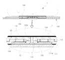
도 2는 본 고안의 일 실시 예에 따른 스마트폰 보호커버용 방향 조절구의 설치 단면도이다.
도 3은 본 고안의 다른 실시 예에 따른 스마트폰 보호커버용 방향 조절구를 도시한 분해 사시도이다.
도 4는 본 고안의 다른 실시 예에 따른 스마트폰 보호커버용 방향 조절구의 설치 단면도이다.
도 5는 본 고안의 또 다른 실시 예에 따른 스마트폰 보호커버용 방향 조절구의 설치 도면이다.
도 6은 도 5에 따른 스마트폰 보호커버용 방향 조절구의 방향 전환 상태도이다.FIG. 1 is an exploded perspective view illustrating a direction control port for a smartphone protective cover according to an embodiment of the present invention.
FIG. 2 is an installation cross-sectional view of a direction control member for a smartphone protective cover according to an embodiment of the present invention.
FIG. 3 is an exploded perspective view showing a direction control port for a smartphone protective cover according to another embodiment of the present invention. FIG.
FIG. 4 is an installation cross-sectional view of a direction control member for a smartphone protective cover according to another embodiment of the present invention; FIG.
FIG. 5 is a view of a directional control for a smartphone protective cover according to another embodiment of the present invention; FIG.
FIG. 6 is a view illustrating a direction switching direction of a direction control port for a smartphone protective cover according to FIG.
이하 본 고안에 따른 스마트폰 보호커버용 방향 조절구를 첨부된 도면을 참고로 하여 상세히 기술되는 실시 예들에 의해 그 특징들을 이해할 수 있을 것이다.Hereinafter, the present invention will be described in detail with reference to the accompanying drawings.
본 고안은 다양한 변경을 가할 수 있고 여러 가지 형태를 가질 수 있는바, 실시 예를 본문에 상세하게 설명하고자 한다. 그러나 이는 본 고안을 특정한 개시 형태에 대해 한정하려는 것이 아니며, 본 고안의 사상 및 기술범위에 포함되는 모든 변경, 균등물 내지 대체물을 포함하는 것으로 이해되어야 한다.The present invention can be variously modified in various forms, and the embodiments are described in detail in the following description. It should be understood, however, that this invention is not intended to be limited to the particular forms disclosed, but is intended to cover all modifications, equivalents, and alternatives falling within the spirit and scope of the invention.
각 도면에서 동일한 참조부호, 특히 십의 자리 및 일의 자리 수, 또는 십의 자리, 일의 자리 및 알파벳이 동일한 참조부호는 동일 또는 유사한 기능을 갖는 부재를 나타내고, 특별한 언급이 없을 경우 도면의 각 참조부호가 지칭하는 부재는 이러한 기준에 준하는 부재로 파악하면 된다.
In the drawings, the same reference numerals are used for the same reference numerals, and in particular, the numerals of the tens and the digits of the digits, the digits of the tens, the digits of the digits and the alphabets are the same, Members referred to by reference numerals can be identified as members corresponding to these standards.
도 1 및 도 2는 본 고안의 일 실시 예에 따른 스마트폰 보호커버용 방향 조절구를 설명하기 위해 도시한 도면들이다.FIG. 1 and FIG. 2 are views illustrating a direction control unit for a smartphone protective cover according to an embodiment of the present invention.
이에 의하면 본 고안에 따른 스마트폰 보호커버용 방향 조절구(100)는 스마트폰 보호커버(10)에 의해 보호되는 스마트폰(1)을 보호커버(10)에서 회동 가능하도록 한다.According to the present invention, the
이때, 상기 스마트폰 보호커버(10)는 스마트폰(1)의 전면부를 보호하는 전면커버(12)와, 상기 스마트폰(1)의 후면부가 밀착되는 후면커버(14)로 이루어진다.The
물론 상기 전면커버(12)와 상기 후면커버(14)의 일측은 접이부(16)에 의해 연결되어 전면커버(12)가 접이부(16)를 중심으로 회동됨으로서, 스마트폰(1)의 전면부를 감싸거나 노출시킬 수 있다.
Of course, one side of the
이와 같은 본 고안에 따른 스마트폰 보호커버용 방향 조절구(100)는 후면커버(14)의 전면에 일체로 고정되되 후면에 원형의 가이드부(112)가 형성되고 상기 가이드부(112)의 중앙에 축공(114)이 형성되고, 상기 축공(114)의 외측에 제1걸림부(116a)를 갖는 복수의 탄성날개(116)가 구비되는 고정판(110)과; 상기 가이드부(112)에 안착되되 상기 축공(114)으로 노출되는 제1축부(122)가 중앙에 돌출 형성되고 상기 제1축부(122)의 외측으로 상기 제1걸림부(116a)에 지지되는 제2걸림부(124)가 구비되는 지지판(120)과; 상기 고정판(110)의 전면에 구비되되 상기 제1축부(122)에 일체로 결합되는 제2축부(132)가 후면에 형성되고, 전면에는 스마트폰(1)의 후면이 탈부착되는 점착부(134)가 구비되는 회전판(130);으로 이루어진다.
The
이하, 각부 구성을 상세히 설명한다.Hereinafter, the configuration of each part will be described in detail.
먼저, 상기 고정판(110)은 스마트폰 보호커버를 구성하는 후면커버(14)의 전면에 일체로 고정된다.First, the
이와 같은 고정판(110)은 원형 디스크 또는 사각 형상 등 다양한 형상으로 이루어지는 몸체(111)의 후면에 원형의 가이드부(112)가 형성되어, 전체적으로 원형 디스크 형상으로 이루어지는 지지판(120)이 회전이 자유롭게 안착된다.The
한편, 상기 고정판(110)의 가이드부(112) 중앙에는 축공(114)이 형성되고, 상기 축공(114)의 외측에는 제1걸림부(116a)를 갖는 복수의 탄성날개(116)가 구비된다.A
그리고 상기 고정판(110)은 가이드부(112)를 제외한 몸체(111)의 후면부가 접착제(111a)로 후면커버(14)의 전면에 일체로 고정된다. 이 경우 고정판(110)이 안정적인 고정 상태를 유지할 수 있도록 상기 후면커버(14)의 전면에는 고정홈(14a)이 형성되어 상기 고정판(110)을 일체로 고정할 수 있다.The rear face of the
이 경우 상기 고정판(110)은 접착제(111a)를 이용해 후면커버(14)의 전면에 고정할 수 있지만, 나사 또는 볼트 체결 등의 다양한 방식으로 고정될 수 있다.
In this case, the
한편, 상기 지지판(120)은 상기 고정판(110)의 후면에 형성되는 가이드부(112)에 안착되어 회전이 가능하도록 원판 형상으로 이루어진다.Meanwhile, the
이와 같은 지지판(120)의 전면 중앙에는 상기 축공(114)으로 노출되도록 제1축부(122)가 돌출 형성되고, 상기 제1걸림부(116a)에 지지되는 제2걸림부(124)가 상기 제1축부(122)의 외측에 형성된다.A
이때, 상기 고정판(110)의 탄성날개(116) 후면에 형성되는 제1걸림부(116a)가 상기 축공(114)을 중심으로 방사상으로 형성되는 경우, 치합이 가능하도록 상기 지지판(120)의 제2걸림부(124) 역시 제1축부(122)를 중심으로 방사상으로 형성된다. 이 경우 상기 제2걸림부(124)는 상기 지지판(120)의 전면에 제1축부(122)를 중심으로 방사상으로 형성되며, 전체적으로 또는 부분적으로 형성될 수 있다.When the first fastening
그리고 상기 지지판(120)의 제1축부(122)는 전단에 일자형 끼움홈(123)이 형성되고, 상기 끼움홈(123)의 중앙에 지지공(123a)이 형성되고, 상기 지지공(123a)의 양측에 지지돌기(123b)가 전방으로 돌출 형성된다.
A
이때 상기 고정판(110)의 탄성날개(116)에 형성되는 제1걸림부(116a)는 복수의 톱니가 연속적으로 형성되어서 이루어지며, 상기 지지판(120)의 제2걸림부(124)도 상기 제1걸림부(116a)와 대응되게 톱니가 연속적으로 형성되어서 이루어진다.
The first
또한, 상기 회전판(130)은 상기 고정판(110)의 전면에 구비되며, 상기 회전판(130)의 전면에는 스마트폰(1)의 후면이 탈부착되는 것으로, 원형 디스크 또는 사각 형상 등 다양한 형상으로 이루어진다.The
상기 회전판(130)은 상기 제1축부(122)에 일체로 결합되는 제2축부(132)가 후면에 형성되고, 표면에는 스마트폰(1)의 후면이 탈부착되는 점착부(134)가 구비된다. 그리고 상기 회전판(130)의 후면에는 상기 고정판(110)의 가이드부(112)가 안착가능한 이탈방지홈(136)이 형성된다.The
이때, 상기 회전판(130)의 제2축부(132)의 단부에 일자형 끼움돌기(133)가 형성되고, 상기 끼움돌기(133)의 중앙에 체결공(133a)이 형성되고, 상기 체결공(133a)의 양측에 지지홈(133b)이 형성된다.At this time, a straight
그리고 상기 회전판(130) 전면에 구비되는 점착부(134)는 점착테이프를 일체로 부착함도 가능하지만, 우레탄 또는 실리콘 계열의 수지에 점착 성분을 가미한 혼합수지를 도포하여서 형성함도 가능하다.
The
이상의 고정판(110)의 후면에 형성된 가이드부(112)에 지지판(120)을 밀착시켜 지지판(120)의 제1축부(122)를 상기 고정판(110)의 축공(114)에 끼우고, 회전판(130)의 제2축부(132)를 제1축부(122)에 접속한다.The
즉, 지지판(120)의 제1축부(122)의 단부에 형성되는 일자형 끼움홈(123)에 회전판(130)의 제2축부(132) 단부에 형성된 일자형 끼움돌기(133)를 끼워 지지돌기(123b)를 지지홈(133b)에 지지시킨 상태에서 체결수단인 나사(140)를 제1축부(122)의 지지공(123a)에 관통시킨 후 제2축부(132)의 체결공(133a)에 나사결합시켜 지지판(120)과 회전판(130)을 일체로 결합시켜준다.
That is, the protruding
이와 같은 구조에 의하면 스마트폰 보호커버(10)를 사용시에는 스마트폰(1)의 후면을 회전판 표면의 점착부(134)에 점착시켜 사용하며, 카메라나 플래시 등을 사용하고자 하는 경우에는 상기 스마트폰(1)을 원하는 각도로 회전시킬 수 있다.According to such a structure, when the smartphone
이 경우 상기 스마트폰(1)을 스마트폰 보호커버(10)의 후면커버(14)에서 회전시키면 회전판(130)과 지지판(120)이 함께 회전하게 되는데, 이때 지지판(120)의 전면에 형성되는 제2걸림부(124)가 고정판(110)의 제1걸림부(116a)를 전방으로 가압하면서 탄성날개(116)가 전진하면서 제2걸림부(124)가 제1걸림부(116a)를 타고넘으면서 회전판이 회전되며, 원하는 각도로 방향이 조절된 경우에는 제2걸림부(124)와 제1걸림부(116a)가 치합된 상태를 유지할 수 있다.In this case, when the
물론, 상기 지지판(120)의 전면에는 90°각도 이내에서 회전이 가능하도록 동일 선상의 곡선형 가이드홈(미도시됨)을 형성하고 고정판(110)의 후면에는 상기 가이드홈(미도시됨)을 따라 안내되는 가이드돌기(미도시됨)를 더 형성할 수 있으며, 상기 회전판(130)과 지지판(120)의 제1 및 제2축부122,132)의 단부 결합 구조는 다양한 형태로 변형될 수 있다.
Of course, curved guide grooves (not shown) are formed in the front surface of the
이와 같은 스마트폰 보호커버용 방향 조절구(100)는 고정판(110)을 스마트폰(1)의 후면부에 일체로 고정하고, 회전판(130)은 후면커버(14)에 점착시켜 필요에 따라 탈부착하는 구조로 사용함도 가능하다. 특히 이와 같은 구조를 별도도 실용신안등록청구범위에 청구하지 아니하여도 작용 방식의 변형에 불과한 정도이므로 이 같은 정도는 당업자에 의해 극히 용이하게 변형실시할 수 있는 정도에 불과하며, 이 같은 변형 예는 본 권리범위 이내의 것에 불과하다.
The
한편, 도 3 및 도 4는 본 고안의 다른 실시 예에 따른 스마트폰 보호커버용 방향 조절구를 설명하기 위해 도시한 도면들이다.3 and 4 are views for explaining a direction control unit for a smartphone protective cover according to another embodiment of the present invention.
이에 의하면 본 고안에 따른 스마트폰 보호커버용 방향 조절구(100)는 고정판(110)의 탄성날개(116)의 단부에 제1걸림부(116a)가 돌기 형상으로 형성되고, 상기 지지판(120)의 제2걸림부(124)는 돌기 형태의 제1걸림부(116a)가 지지되는 돌기홈 형상으로 형성된다.The
이때, 상기 탄성날개(116)는 고정판(110)의 축공(114)을 중심으로 90°간격으로 방사상으로 형성되고, 상기 지지판(120)의 돌기홈 형상으로 이루어지는 제2걸림부(124)도 제1축부(122)를 중심으로 90°간격으로 방사상으로 형성된다.At this time, the
또한, 상기 제1걸림부(116a)의 일측에는 경사면(116b)이 형성되어 상기 회전판(130)이 일방향으로만 회전이 가능하고, 반대방향으로 회전하는 것을 방지할 수 있다.In addition, an
이와 같은 구조에 의하면 회전판(130)을 일방향으로 회전시키게 되면 90°간격으로 회전이 가능해 스마트폰(1)의 보호커버(10) 상에서 가로방향 또는 세로방향으로 방향전환을 용이하게 수행할 수 있는 장점이 있다.
According to this structure, when the
또한, 도 5 및 도 6은 본 고안의 또 다른 실시 예에 따른 스마트폰 보호커버용 방향 조절구를 설명하기 위해 도시한 도면들이다.5 and 6 are views for explaining a direction adjusting member for a smartphone protective cover according to another embodiment of the present invention.
이에 의하면 상기 회전판(130)의 측면에는 자석(138)이 연장부(137)에 의해 일체로 고정되고, 스마트폰 보호커버(10)의 전면커버(12)의 일단에는 상기 자석(138)에 달라붙는 판(plate) 형상의 금속부재(17)가 일체로 부착 또는 내장된다.The
이와 같은 구조에 의하면 스마트폰(1)의 전면부를 보호하기 위해 전면커버(12)를 덮게 되면 회전판(130)의 측면에 고정되는 자석(138)에 부착되어 스마트폰(1)의 전면부를 더욱 충실히 보호할 수 있다.According to this structure, when the
물론 상기 회전판(130)의 측면에 금속부재(17)가 일체로 고정되고, 자석(138)을 전면커버(12)의 일단에 부착 또는 내장함도 가능하며, 이 같은 위치 변경은 모두 본 고안의 권리범위 이내의 변형에 불과하다.
Of course, the
이상의 설명에서 본 고안은 특정의 실시 예와 관련하여 도시 및 설명하였지만, 실용신안등록청구범위에 의해 나타난 고안의 사상 및 영역으로부터 벗어나지 않는 한도 내에서 다양한 개조 및 변화 가능하다는 것을 이 기술분야에서 통상의 지식을 가진 자라면 누구나 쉽게 알 수 있을 것이다.
While the present invention has been particularly shown and described with reference to exemplary embodiments thereof, it will be understood by those skilled in the art that various changes in form and details may be made therein without departing from the spirit and scope of the invention as defined by the appended claims. Anyone with knowledge will know easily.
1: 스마트폰 10: 스마트폰 보호커버
12: 전면커버 14: 후면커버
100: 방향 조절구 110: 고정판
120: 지지판 130: 회전판1: Smartphone 10: Smartphone protection cover
12: Front cover 14: Rear cover
100: Direction adjuster 110: Fixing plate
120: support plate 130:
Claims (9)
Translated fromKorean상기 제1축부(122)의 단부에는 일자형 끼움홈(123)이 형성되고, 상기 끼움홈(123)의 중앙에 지지공(123a)이 형성되고, 상기 지지공(123a)의 양측에 지지돌기(123b)가 전방으로 돌출 형성되며;
상기 제2축부(132)의 단부에는 상기 일자형 끼움홈(123)에 일자형 끼움돌기(133)가 형성되고, 상기 끼움돌기(133)의 중앙에 체결공(133a)이 형성되고, 상기 체결공(133a)의 양측에 지지홈(133b)이 형성되어;
상기 일자형 끼움홈(123)에 상기 일자형 끼움돌기(133)를 끼워 상기 지지돌기(123b)를 지지홈(133b)에 지지시킨 상태에서 나사(140)를 상기 지지공(123a)에 관통시켜 제2축부(132)의 체결공(133a)에 나사결합시켜 상기 지지판(120)과 회전판(130)을 일체로 결합한 것을 특징으로 하는 스마트폰 보호커버용 방향 조절구.
A circular guide portion 112 is integrally fixed to the front surface of the rear cover 14 of the smartphone protective cover 10 for protecting the smartphone 1 and a circular guide portion 112 is formed on the rear surface thereof, (110) having a plurality of elastic blades (116) having a first engaging portion (116a) formed on the outer side of the shaft hole (114); A first shaft portion 122 which is seated on the guide portion 112 and is exposed to the shaft hole 114 is protruded at the center and supported by the first engaging portion 116a to the outside of the first shaft portion 122 A support plate 120 having a second latching part 124; A rotary shaft 130 is provided on the front surface of the fixing plate 110 and has a second shaft portion 132 integrally coupled to the first shaft portion 122 and a rear surface of the rotary shaft 130, ≪ / RTI >
The end of the first shaft portion 122 is formed with a straight fitting groove 123. A support hole 123a is formed at the center of the fitting groove 123 and a support protrusion 123b projecting forwardly;
The end of the second shaft portion 132 is provided with a protrusion 133 formed in the protrusion 123 and a protrusion 133 is formed at the center of the protrusion 133, 133a on both sides thereof;
The screw 140 is passed through the support hole 123a in a state in which the protrusion 123b of the protrusion 123 is inserted into the protrusion 123 of the protrusion 123 and the protrusion 123b of the protrusion 123b is supported by the protrusion 133b, And the supporting plate 120 and the rotary plate 130 are integrally coupled to each other by being screwed to the fastening holes 133a of the shaft portion 132. [
상기 고정판(110)은 몸체(111)의 후면부가 접착제(111a)로 후면커버(14)의 전면에 일체로 고정되는 것을 특징으로 하는 스마트폰 보호커버용 방향 조절구.
The method according to claim 1,
Wherein the fixing plate 110 is integrally fixed to the front surface of the rear cover 14 with a rear portion of the body 111 as an adhesive 111a.
상기 제1걸림부(116a)는 복수의 톱니가 연속적으로 형성되어서 이루어지며, 상기 지지판(120)의 제2걸림부(124)는 상기 제1걸림부(116a)와 대응되게 톱니가 연속적으로 형성되어서 이루어진 것을 특징으로 하는 스마트폰 보호커버용 방향 조절구.
The method according to claim 1,
The first engaging portion 116a is formed by continuously forming a plurality of teeth and the second engaging portion 124 of the support plate 120 is continuously formed with teeth corresponding to the first engaging portion 116a And a directional control port for a smartphone protective cover.
상기 회전판(130)은 상기 제1축부(122)에 일체로 결합되는 제2축부(132)가 후면에 형성되고, 상기 회전판(130)의 표면에는 스마트폰(1)의 후면이 탈부착 가능한 점착부(134)가 구비되는 것을 특징으로 하는 스마트폰 보호커버용 방향 조절구.
The method according to claim 1,
The rotation plate 130 has a second shaft 132 integrally coupled to the first shaft 122 on the rear surface of the rotation plate 130. The rear surface of the rotation plate 130 is attached to the rear surface of the rotary shaft 130, (134) are provided on the side surface of the case.
상기 제1걸림부(116a)는 상기 탄성날개(116)의 단부에 돌기 형상으로 형성되고, 상기 제2걸림부(124)는 상기 제1걸림부(116a)가 지지되는 돌기홈 형상으로 형성되는 것을 특징으로 하는 스마트폰 보호커버용 방향 조절구.
The method according to claim 1,
The first latching part 116a is formed in a protruding shape at the end of the elastic blade 116 and the second latching part 124 is formed in a protruding groove shape in which the first latching part 116a is supported Wherein the directional adjuster is for a smartphone protective cover.
상기 탄성날개(116)는 고정판(110)의 축공(114)을 중심으로 90°간격으로 방사상으로 형성되고, 상기 제2걸림부(124)는 지지판(120)의 제1축부(122)를 중심으로 90°간격으로 방사상으로 형성되는 것을 특징으로 하는 스마트폰 보호커버용 방향 조절구.
6. The method of claim 5,
The elastic wings 116 are radially formed at intervals of 90 degrees around the shaft hole 114 of the fixing plate 110. The second locking portions 124 are formed in the center of the first shaft portion 122 of the support plate 120, In a radial direction at intervals of 90 degrees.
상기 제1걸림부(116a)의 일측에는 경사면(116b)이 더 형성되는 것을 특징으로 하는 스마트폰 보호커버용 방향 조절구.
6. The method of claim 5,
And a slope (116b) is further formed on one side of the first latching part (116a).
상기 회전판(130)의 측면에는 자석(138)이 연장부(137)에 의해 일체로 고정되고, 스마트폰 보호커버(10)의 전면커버(12)의 일단에는 상기 자석(138)에 달라붙는 금속부재(17)가 일체로 구비되는 것을 특징으로 하는 스마트폰 보호커버용 방향 조절구.
The method according to claim 1,
A magnet 138 is integrally fixed to the side surface of the rotary plate 130 by an extension 137 and one end of a front cover 12 of the smartphone protective cover 10 is fixed to the magnet 138 And a member (17) are integrally provided on the side surface of the cover (10).
Priority Applications (1)
| Application Number | Priority Date | Filing Date | Title |
|---|---|---|---|
| KR2020140008050UKR200481417Y1 (en) | 2014-11-05 | 2014-11-05 | A direction adjusting apparatus for smartphone cover |
Applications Claiming Priority (1)
| Application Number | Priority Date | Filing Date | Title |
|---|---|---|---|
| KR2020140008050UKR200481417Y1 (en) | 2014-11-05 | 2014-11-05 | A direction adjusting apparatus for smartphone cover |
Publications (2)
| Publication Number | Publication Date |
|---|---|
| KR20160001591U KR20160001591U (en) | 2016-05-13 |
| KR200481417Y1true KR200481417Y1 (en) | 2016-09-29 |
Family
ID=56023989
Family Applications (1)
| Application Number | Title | Priority Date | Filing Date |
|---|---|---|---|
| KR2020140008050UExpired - Fee RelatedKR200481417Y1 (en) | 2014-11-05 | 2014-11-05 | A direction adjusting apparatus for smartphone cover |
Country Status (1)
| Country | Link |
|---|---|
| KR (1) | KR200481417Y1 (en) |
Families Citing this family (1)
| Publication number | Priority date | Publication date | Assignee | Title |
|---|---|---|---|---|
| KR200494738Y1 (en)* | 2020-10-07 | 2021-12-10 | 김동열 | Sliding adsorber for mobile phone case |
Citations (3)
| Publication number | Priority date | Publication date | Assignee | Title |
|---|---|---|---|---|
| KR200465995Y1 (en) | 2011-01-20 | 2013-03-21 | 주식회사 솔로젠 | Case for portable terminal |
| KR200468007Y1 (en)* | 2013-02-22 | 2013-07-23 | 안종출 | Folding portable phone case with phone holder with rotation and linear motion |
| KR101394285B1 (en)* | 2013-11-18 | 2014-05-14 | 주식회사 슈피겐코리아 | Connecting device opening and shutting front cover of portable electronic device and case thereof |
Family Cites Families (1)
| Publication number | Priority date | Publication date | Assignee | Title |
|---|---|---|---|---|
| KR20130020817A (en)* | 2013-01-14 | 2013-02-28 | 이주영 | Pocketbook type mobile phone case |
- 2014
- 2014-11-05KRKR2020140008050Upatent/KR200481417Y1/ennot_activeExpired - Fee Related
Patent Citations (3)
| Publication number | Priority date | Publication date | Assignee | Title |
|---|---|---|---|---|
| KR200465995Y1 (en) | 2011-01-20 | 2013-03-21 | 주식회사 솔로젠 | Case for portable terminal |
| KR200468007Y1 (en)* | 2013-02-22 | 2013-07-23 | 안종출 | Folding portable phone case with phone holder with rotation and linear motion |
| KR101394285B1 (en)* | 2013-11-18 | 2014-05-14 | 주식회사 슈피겐코리아 | Connecting device opening and shutting front cover of portable electronic device and case thereof |
Also Published As
| Publication number | Publication date |
|---|---|
| KR20160001591U (en) | 2016-05-13 |
Similar Documents
| Publication | Publication Date | Title |
|---|---|---|
| US20120236475A1 (en) | Digital photo frame | |
| TWI344780B (en) | Protective cover adapted for use in an electronic device | |
| US20180184773A1 (en) | Case and mount for handheld electronic device | |
| CN105652968A (en) | Protection device and fixing frame assembly | |
| KR20040005410A (en) | Camera lens module and portable wireless terminal therewith | |
| US20150346767A1 (en) | Wearable electronic device | |
| WO2020000509A1 (en) | Photographing apparatus protection case having detachable external camera | |
| CN101861062A (en) | Portable electronic device | |
| WO2013010397A1 (en) | Protective case for mobile device | |
| EP1739767B1 (en) | Battery cover fixing means for portable terminal | |
| CN108697210B (en) | A kind of bracelet clasp of dual fine-tuning watchband length | |
| KR200481417Y1 (en) | A direction adjusting apparatus for smartphone cover | |
| CN101936330A (en) | Hinge structure | |
| KR101605403B1 (en) | Case for mobile apparatus | |
| CN215956803U (en) | Snap components, housing components, electronic equipment, protective shells and electronic equipment components | |
| US8923001B2 (en) | Chip card protecting cover assembly and electronic device using same | |
| KR20160002387U (en) | Edge-replaceable smartphone case using thermoplastic poly urethane elastomer | |
| CN206640653U (en) | A magnetic mobile phone camera lens assembly | |
| KR20140109225A (en) | battery cover for smart-phone with camera lens | |
| KR20120103831A (en) | Functional case for mobile phone | |
| KR20180026640A (en) | Privacy protecting camera cover | |
| KR101963517B1 (en) | Finger holder for mobile terminal | |
| CN117459617A (en) | Adjustment mechanism and electronic equipment components | |
| KR101738616B1 (en) | Apparatus for mounting mobile phone | |
| KR20180002445U (en) | Mobile phone auxiliary battery |
Legal Events
| Date | Code | Title | Description |
|---|---|---|---|
| A201 | Request for examination | ||
| UA0108 | Application for utility model registration | St.27 status event code:A-0-1-A10-A12-nap-UA0108 | |
| UA0201 | Request for examination | St.27 status event code:A-1-2-D10-D11-exm-UA0201 | |
| D13-X000 | Search requested | St.27 status event code:A-1-2-D10-D13-srh-X000 | |
| D14-X000 | Search report completed | St.27 status event code:A-1-2-D10-D14-srh-X000 | |
| E902 | Notification of reason for refusal | ||
| UE0902 | Notice of grounds for rejection | St.27 status event code:A-1-2-D10-D21-exm-UE0902 | |
| E13-X000 | Pre-grant limitation requested | St.27 status event code:A-2-3-E10-E13-lim-X000 | |
| P11-X000 | Amendment of application requested | St.27 status event code:A-2-2-P10-P11-nap-X000 | |
| P13-X000 | Application amended | St.27 status event code:A-2-2-P10-P13-nap-X000 | |
| E701 | Decision to grant or registration of patent right | ||
| UE0701 | Decision of registration | St.27 status event code:A-1-2-D10-D22-exm-UE0701 | |
| UG1501 | Laying open of application | St.27 status event code:A-1-1-Q10-Q12-nap-UG1501 | |
| R18-X000 | Changes to party contact information recorded | St.27 status event code:A-5-5-R10-R18-oth-X000 | |
| REGI | Registration of establishment | ||
| UR0701 | Registration of establishment | St.27 status event code:A-2-4-F10-F11-exm-UR0701 | |
| UR1002 | Payment of registration fee | St.27 status event code:A-2-2-U10-U11-oth-UR1002 Fee payment year number:1 | |
| R18-X000 | Changes to party contact information recorded | St.27 status event code:A-5-5-R10-R18-oth-X000 | |
| UG1601 | Publication of registration | St.27 status event code:A-4-4-Q10-Q13-nap-UG1601 | |
| P22-X000 | Classification modified | St.27 status event code:A-4-4-P10-P22-nap-X000 | |
| R18-X000 | Changes to party contact information recorded | St.27 status event code:A-5-5-R10-R18-oth-X000 | |
| P22-X000 | Classification modified | St.27 status event code:A-4-4-P10-P22-nap-X000 | |
| UC1903 | Unpaid annual fee | St.27 status event code:A-4-4-U10-U13-oth-UC1903 Not in force date:20190923 Payment event data comment text:Termination Category : DEFAULT_OF_REGISTRATION_FEE | |
| UC1903 | Unpaid annual fee | St.27 status event code:N-4-6-H10-H13-oth-UC1903 Ip right cessation event data comment text:Termination Category : DEFAULT_OF_REGISTRATION_FEE Not in force date:20190923 | |
| P22-X000 | Classification modified | St.27 status event code:A-4-4-P10-P22-nap-X000 |