KR200475741Y1 - Stick for self photo - Google Patents
Stick for self photoDownload PDFInfo
- Publication number
- KR200475741Y1 KR200475741Y1KR2020140005479UKR20140005479UKR200475741Y1KR 200475741 Y1KR200475741 Y1KR 200475741Y1KR 2020140005479 UKR2020140005479 UKR 2020140005479UKR 20140005479 UKR20140005479 UKR 20140005479UKR 200475741 Y1KR200475741 Y1KR 200475741Y1
- Authority
- KR
- South Korea
- Prior art keywords
- photographing means
- photographing
- pedestal
- self
- stick
- Prior art date
- Legal status (The legal status is an assumption and is not a legal conclusion. Google has not performed a legal analysis and makes no representation as to the accuracy of the status listed.)
- Expired - Fee Related
Links
Images


Classifications
- G—PHYSICS
- G03—PHOTOGRAPHY; CINEMATOGRAPHY; ANALOGOUS TECHNIQUES USING WAVES OTHER THAN OPTICAL WAVES; ELECTROGRAPHY; HOLOGRAPHY
- G03B—APPARATUS OR ARRANGEMENTS FOR TAKING PHOTOGRAPHS OR FOR PROJECTING OR VIEWING THEM; APPARATUS OR ARRANGEMENTS EMPLOYING ANALOGOUS TECHNIQUES USING WAVES OTHER THAN OPTICAL WAVES; ACCESSORIES THEREFOR
- G03B17/00—Details of cameras or camera bodies; Accessories therefor
- G03B17/56—Accessories
- G03B17/561—Support related camera accessories
- F—MECHANICAL ENGINEERING; LIGHTING; HEATING; WEAPONS; BLASTING
- F16—ENGINEERING ELEMENTS AND UNITS; GENERAL MEASURES FOR PRODUCING AND MAINTAINING EFFECTIVE FUNCTIONING OF MACHINES OR INSTALLATIONS; THERMAL INSULATION IN GENERAL
- F16M—FRAMES, CASINGS OR BEDS OF ENGINES, MACHINES OR APPARATUS, NOT SPECIFIC TO ENGINES, MACHINES OR APPARATUS PROVIDED FOR ELSEWHERE; STANDS; SUPPORTS
- F16M11/00—Stands or trestles as supports for apparatus or articles placed thereon ; Stands for scientific apparatus such as gravitational force meters
- F16M11/02—Heads
- F16M11/04—Means for attachment of apparatus; Means allowing adjustment of the apparatus relatively to the stand
- F16M11/041—Allowing quick release of the apparatus
- F—MECHANICAL ENGINEERING; LIGHTING; HEATING; WEAPONS; BLASTING
- F16—ENGINEERING ELEMENTS AND UNITS; GENERAL MEASURES FOR PRODUCING AND MAINTAINING EFFECTIVE FUNCTIONING OF MACHINES OR INSTALLATIONS; THERMAL INSULATION IN GENERAL
- F16M—FRAMES, CASINGS OR BEDS OF ENGINES, MACHINES OR APPARATUS, NOT SPECIFIC TO ENGINES, MACHINES OR APPARATUS PROVIDED FOR ELSEWHERE; STANDS; SUPPORTS
- F16M13/00—Other supports for positioning apparatus or articles; Means for steadying hand-held apparatus or articles
- F16M13/02—Other supports for positioning apparatus or articles; Means for steadying hand-held apparatus or articles for supporting on, or attaching to, an object, e.g. tree, gate, window-frame, cycle
- F16M13/022—Other supports for positioning apparatus or articles; Means for steadying hand-held apparatus or articles for supporting on, or attaching to, an object, e.g. tree, gate, window-frame, cycle repositionable
- G—PHYSICS
- G03—PHOTOGRAPHY; CINEMATOGRAPHY; ANALOGOUS TECHNIQUES USING WAVES OTHER THAN OPTICAL WAVES; ELECTROGRAPHY; HOLOGRAPHY
- G03B—APPARATUS OR ARRANGEMENTS FOR TAKING PHOTOGRAPHS OR FOR PROJECTING OR VIEWING THEM; APPARATUS OR ARRANGEMENTS EMPLOYING ANALOGOUS TECHNIQUES USING WAVES OTHER THAN OPTICAL WAVES; ACCESSORIES THEREFOR
- G03B17/00—Details of cameras or camera bodies; Accessories therefor
- G03B17/38—Releasing-devices separate from shutter
- H—ELECTRICITY
- H04—ELECTRIC COMMUNICATION TECHNIQUE
- H04N—PICTORIAL COMMUNICATION, e.g. TELEVISION
- H04N23/00—Cameras or camera modules comprising electronic image sensors; Control thereof
- H04N23/60—Control of cameras or camera modules
- H04N23/66—Remote control of cameras or camera parts, e.g. by remote control devices
- H04N23/661—Transmitting camera control signals through networks, e.g. control via the Internet
Landscapes
- Engineering & Computer Science (AREA)
- General Engineering & Computer Science (AREA)
- Physics & Mathematics (AREA)
- General Physics & Mathematics (AREA)
- Mechanical Engineering (AREA)
- Multimedia (AREA)
- Signal Processing (AREA)
- Studio Devices (AREA)
Abstract
Translated fromKoreanDescription
Translated fromKorean본 고안은 셀카 스틱에 관한 것으로, 보다 상세하게는 카메라나 휴대단말기 등의 촬영수단을 거치하여 자신의 모습을 직접 촬영할 수 있도록 구성된 셀카 스틱에 관한 것이다.
The present invention relates to a self-stick, and more particularly, to a self-stick configured to take a photograph of himself or herself through a photographing means such as a camera or a portable terminal.
일반적으로 셀카란 영어의 한국식 표현인 셀프 카메라(self camera)를 줄여 이르는 우리나라에서 만들어진 신조어로서, 자신이 직접 자신의 모습을 스스로 촬영하는 행위를 말한다.Generally speaking, the word 'self' is a coined word in Korean that reduces the self-camera, which is a Korean expression of English, and refers to an act of self-photographing itself.
이는 촬영자 자신이 소지한 카메라나 휴대단말기 등의 촬영수단에 구비된 폰카메라의 렌즈가 자신을 향하도록 하여 자신을 피사체로 촬영하는 것으로, 영어 표현으로는 셀피(selfie)라고 하고, 셀피는 영어사전으로 유명한 옥스포드 대학 출판사에 의해 2013년 올해의 단어로 선정된 바 있다.This means that a lens of a phone camera provided in a photographing means such as a camera or a portable terminal possessed by the photographer himself shoots himself / herself with a subject, and is called a selfie in English expression, In the year 2013 by the famous Oxford University Press.
셀카는 특히 고화질 폰카메라가 구비된 스마트폰이 전 세계적으로 널리 보급되면서 카메라 대신에 스마트폰을 통하여 쉽게 자기 자신을 촬영하는 일이 일상화되었고, 연예인은 물론이고 일반인들까지 셀카로 찍은 사진을 블로그나 SNS를 통해 다른 사람들과 공유하면서 널리 유행하고 있다.Especially, smart phones equipped with high-quality phone cameras have become popular all over the world, so it is common for them to easily photograph themselves through a smart phone instead of a camera, and the photographs taken by self- Sharing with others through SNS.
종래에 셀카를 찍는 방법은 촬영수단의 렌즈가 자신을 향하도록 든 채 팔을 앞으로 뻗어 자신의 모습을 촬영하였으나 촬영자가 촬영될 자신의 모습을 미리 볼 수가 없어 촬영이 불편하였다. 최근에는 셀카 촬영 기능을 갖는 카메라나 휴대단말기가 보급되어 촬영자가 촬영될 자신의 모습을 미리 보면서 셀카를 찍을 수 있다.Conventionally, in the method of taking a self-portrait, the lens of the photographing means is directed toward the user, and the user stretches his / her arm forward to take a picture of himself, but the photographer can not preview his / her own image to be photographed. Recently, a camera or a portable terminal having a self-photographing function is popularized, and a photographer can take a self-portrait while previewing his / her own image to be photographed.
그러나, 촬영자가 촬영수단(C)을 직접 들고 셀카를 찍는 것은 번거로울 뿐만 아니라, 촬영자의 머리나 상반신만 크게 나오고 뒷 배경은 거의 나오지 않으며, 여러 명이 함께 셀카를 찍는 경우 서로 억지로 붙어 있어야 되기 때문에 불편한 문제가 있다.However, it is not only troublesome for the photographer to take the self-portrait (C) directly, but also the photographer's head or upper body is largely out and the back background is hardly displayed. .
이를 해결하기 위하여 셀카 스틱이 개발되었다. 도 1은 종래기술의 셀카 스틱의 도면인데, 종래기술의 셀카 스틱은 촬영자가 파지하는 손잡이(10)와, 상기 손잡이(10)와 거치대(30)를 연결하여 길게 신장되는 폴대(20)와, 상기 폴대(20)에 연결되어 휴대단말기를 고정 거치하는 거치대(30)를 포함하여 이루어진다.To solve this problem, a self-stick was developed. FIG. 1 is a view of a prior art cellular phone. The prior art cellular phone includes a
하지만, 종래기술의 셀카 스틱은 폴대(20) 끝단의 거치대(30)에 촬영수단(C)을 거치하기 때문에 촬영자가 촬영수단(C)을 직접 조작할 수 없어 타이머를 사용해야 하므로 촬영이 용이하지 않은 문제가 있다.However, since the self-stick of the prior art mounts the photographing means C on the mount table 30 at the end of the
또한, 촬영을 위한 리모컨이 제공된다고 하더라도 셀카 스틱과 별개로 구성되어 있어, 리모콘을 손에 든 채 사진을 찍거나, 양손을 모두 이용하여 사진을 찍어야 하므로 사용이 불편하고 리모컨이 분실될 위험도 있다.Also, even if a remote control for shooting is provided, it is separate from the self-stick, so it is inconvenient to use the remote control in the hand or take a picture with both hands, and the remote control may be lost.
더불어, 폴대(20)는 다단으로 서로 연결되어 있고 그 단면이 원형으로 이루어져, 폴대(20)를 신장시키거나, 촬영자가 길게 신장된 셀카 스틱을 들고 셀카를 찍을 때 폴대(20)가 회전되어 정확한 촬영이 어려워 불편한 문제가 있다.In addition, the
또한, 거치대(30)가 촬영수단(C)을 확실하게 고정하지 못하여 사용 중 촬영수단(C)이 유동되거나 거치대(30)로부터 이탈될 수 있고, 거치와 분리 과정에서 촬영수단(C)이 거치대의 표면과 마찰되어 흠집이나 스크래치 등의 손상이 발생할 수 있는 문제가 있다.
The photographing means C can be moved or released from the
본 고안은 상술한 문제들을 모두 해결하기 위하여 안출된 것으로, 블루투스 모듈을 이용하여 촬영수단을 제어하는 리모콘이 내장되어 있어 촬영이 용이하고, 리모콘을 든 채 사진을 찍거나 양손을 모두 사용하지 않아도 되므로 촬영이 편리하며, 폴대에 길이 방향으로 홈을 형성하여 다단으로 이루어진 폴대가 회전되거나 유동되지 않으므로 정확한 촬영이 가능하고, 거치부재가 촬영수단을 확실하게 고정하여 사용 중 촬영수단이 유동되거나 이탈되지 않고 거치와 분리 과정에서 촬영수단에 흠집이나 스크래치 등의 손상이 발생되지 않으며, LED 램프를 구비하여 촬영용 조명으로 사용하거나 소형 랜턴으로 활용할 수 있는 셀카 스틱의 제공에 그 목적이 있다.
The present invention has been devised to solve all of the above problems. The remote control for controlling the photographing means using the Bluetooth module is built in, so that the photographing is easy, and the user does not need to take a picture with the remote control or use both hands It is possible to take a photograph accurately and to fix the photographing means securely so that the photographing means is not moved or released during use And it is an object of the present invention to provide a self-stick which does not cause damage such as scratches or scratches on a photographing means during a mounting and separation process, and is equipped with an LED lamp and used as a photographing light or as a small lantern.
상기 과제를 해결하기 위하여 본 고안은 블루투스 모듈과 촬영 버튼이 구비된 리모콘이 내장되어 있는 손잡이부재; 상기 손잡이부재의 전방에 연결되고 다수의 폴대들이 서로 인출입 가능하게 연결된 폴대부재; 및 상기 폴대부재의 전방에 연결되고 촬영수단이 거치되는 거치부재;를 포함하는 셀카 스틱을 제공한다.According to an aspect of the present invention, there is provided a remote control device comprising: a handle member having a Bluetooth module and a remote controller provided with a photographing button; A pole member connected to the front of the pull member and having a plurality of poles pivotably connected to each other; And a mounting member connected to the front of the pole member and to which the photographing means is mounted.
이때, 상기 손잡이부재는, 상기 블루투스 모듈을 온/오프시키는 스위치와, 상기 블루투스 모듈의 작동을 위한 전원을 충전하기 위한 단자를 더 포함하는 것에도 그 특징이 있다.In this case, the handle member may further include a switch for turning on / off the Bluetooth module and a terminal for charging a power source for operating the Bluetooth module.
게다가, 상기 폴대부재의 폴대들은 길이 방향을 따라 길이홈이 형성되고, 상기 폴대들의 고정홈은 서로 연결이 되도록 배치되는 것에도 그 특징이 있다.In addition, the pole members of the pole member are formed with longitudinal grooves along the longitudinal direction, and the fixing grooves of the poles are arranged to be connected to each other.
뿐만 아니라, 상기 거치부재는, 촬영수단의 하부를 받치는 하부 받침대와, 상기 하부 받침대의 일측에 연결된 측부 받침대와, 상기 하부 받침대의 타측 후방에 연결되어 촬영수단의 후면을 받치는 후면 받침대를 포함하는 것에도 그 특징이 있다.In addition, the mounting member may include a lower pedestal supporting the lower portion of the photographing means, a side pedestal connected to one side of the lower pedestal, and a rear pedestal connected to the other rear side of the lower pedestal to support the rear side of the photographing means There are also features.
여기서, 상기 측부 받침대는 "ㄴ"자 형상으로 이루어지고, 상기 하부 받침대에 슬라이딩 이동 가능하게 연결되며, 상기 거치부재 양측의 폭 크기의 조절이 가능하게 구성된 것에도 그 특징이 있다.Here, the side pedestal is formed in a "B" shape, and is slidably connected to the lower pedestal, and the width size of both sides of the stationary member is adjustable.
더불어, "ㄱ"자 형상으로 이루어진 상부 받침대가 상기 후면 받침대의 내측에 스프링이 개재된 채 상하 방향으로 인출입되도록 연결 설치되고, 상기 상부 받침대의 상단에 고무나 실리콘으로 이루어진 패킹이 결합된 것에도 그 특징이 있다.In addition, an upper pedestal having an "a" shape is connected to the inside of the rear pedestal so as to be vertically extended with a spring interposed therebetween, and a rubber or silicone packing is coupled to the upper end of the upper pedestal There are features.
이와 함께, 상기 하부 받침대와 측면 받침대는 내측면에 안착패드가 부착되어 있는 것에도 그 특징이 있다.In addition, the lower pedestal and the side pedestal are also characterized in that a seating pad is attached to the inner surface.
또한, 상기 폴대부재와 거치부재를 연결하여 상기 거치부재가 회전 가능하게 구비되도록 하는 연결부재;를 더 포함하는 것에도 그 특징이 있다.Further, the present invention is also characterized by a connecting member connecting the pole member and the mounting member to allow the mounting member to be rotatable.
나아가, 상기 연결부재는, 상기 폴대부재의 전단과 결합되고 수평 방향으로 결합공이 관통 형성된 결합편과, 상측으로 돌출 형성되어 거치부재의 거치공과 연결되는 연결나사와, 상기 연결나사를 회전시키는 다이얼과, 하부 양측에 형성되어 상기 결합편의 양측을 감싸도록 결합되는 고리편을 포함하는 연결본체와, 상기 연결본체가 상기 결합편에 회전 가능하게 연결되도록 상기 결합편과 고리편에 수평 방향으로 연결되고 레버를 구비한 조절나사를 포함하는 것에도 그 특징이 있다.Further, the connecting member may include an engaging piece engaged with the front end of the pole member and formed with a through hole in a horizontal direction, a connecting screw protruding upward and connected to the mounting hole of the mounting member, a dial for rotating the connecting screw, A coupling body formed on both sides of the lower portion and including a loop piece coupled to surround both sides of the coupling piece; and a connecting body connected to the coupling piece and the loop piece in a horizontal direction so as to be rotatably connected to the coupling piece, And an adjusting screw provided with an adjusting screw.
아울러, 상기 조절나사의 외주에 단속부재가 설치되되, 상기 단속부재는, 외주에 복수 개의 고정편이 돌출 형성되어 상기 고리편의 고리홀 내주에 형성된 고정홈에 고정되고, 선단면에 복수 개의 돌부와 홈부가 교대로 형성된 단속면을 구비하여 상기 결합편의 타측에 형성된 복수개의 돌부와 홈부가 교대로 형성된 단속면과 접촉되면서 상기 연결본체의 회전이 단속되는 것에도 그 특징이 있다.In addition, an intermittent member is provided on the outer periphery of the adjusting screw, and the intermittent member is fixed to a fixing groove formed on the inner periphery of the annular hole of the annular portion, with a plurality of fixing pieces protruding from the outer periphery, And the rotation of the connection body is interrupted while being brought into contact with an intermittent surface formed alternately with a plurality of projections and grooves formed on the other side of the engagement piece.
한편, 상기 연결부재는 조명수단이 설치되어 있는 것에도 그 특징이 있다.
On the other hand, the connecting member is also characterized in that the lighting means is provided.
본 고안에 의하면, 블루투스 모듈을 이용하여 촬영수단을 제어하는 리모콘이 내장되어 있어 촬영이 용이하고, 리모콘을 든 채 사진을 찍거나 양손을 모두 사용하지 않아도 되므로 촬영이 편리하며, 폴대에 길이 방향으로 홈을 형성하여 다단으로 이루어진 폴대가 회전되거나 유동되지 않으므로 정확한 촬영이 가능하고, 거치부재가 촬영수단을 확실하게 고정하여 사용 중 촬영수단이 유동되거나 이탈되지 않고 거치와 분리 과정에서 촬영수단에 흠집이나 스크래치 등의 손상이 발생되지 않으며, LED 램프를 구비하여 촬영용 조명으로 사용하거나 소형 랜턴으로 활용할 수 있는 효과가 있다.
According to the present invention, the remote control for controlling the photographing means is built in using the Bluetooth module, so that the photographing is easy, the photograph is taken with the remote control held, the both hands are not used, Since the multi-stepped poles are not rotated or flowed, accurate photographing is possible, and the stationary member securely fixes the photographing means, so that the photographing means does not flow or fall off during use, There is no damage such as scratches, and an LED lamp is provided, which can be used as illumination for shooting or as a small lantern.
도 1은 종래기술의 셀카 스틱을 도시한 사시도이다.
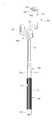
도 2a 및 도 2b는 본 고안의 실시예에 따른 셀카 스틱의 결합 사시도이다.
도 3은 본 고안의 실시예에 따른 셀카 스틱의 분리 사시도이다.
도 4는 본 고안의 실시예에 따른 셀카 스틱의 손잡이부재와 폴대부재의 상세 도면이다.
도 5(a) 및 도 5(b)는 본 고안의 실시예에 따른 셀카 스틱의 거치부재의 상세 도면이다.
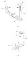
도 6은 본 고안의 실시예에 따른 셀카 스틱의 연결부재가 포함된 분리 사시도이다.
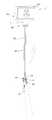
도 7은 본 고안의 실시예에 따른 셀카 스틱의 사용 상태도이다.1 is a perspective view showing a prior art self-stick.
FIGS. 2A and 2B are perspective views of a self-stick according to an embodiment of the present invention; FIG.
3 is an exploded perspective view of a self-stick according to an embodiment of the present invention.
FIG. 4 is a detailed view of a pull member and a pole member of a self-stick according to an embodiment of the present invention.
5 (a) and 5 (b) are detailed drawings of a mounting member of a self-stick according to an embodiment of the present invention.
6 is an exploded perspective view illustrating a connecting member of a self-stick according to an embodiment of the present invention.
7 is a use state diagram of the self-stick according to the embodiment of the present invention.
이하, 본 고안의 구성에 대하여 도면을 참조하여 실시예를 중심으로 상세히 설명한다.Hereinafter, the configuration of the present invention will be described in detail with reference to the drawings with reference to the drawings.
도 2a 내지 도 3을 참고하면, 본 고안에 따른 셀카 스틱(1)은 카메라나 휴대단말기 등의 촬영수단(C)을 거치하여 자신의 모습을 직접 촬영할 수 있도록 구성된 것으로, 손잡이부재(100), 폴대부재(200) 및 거치부재(300)를 포함하여 이루어지고, 여기서 연결부재(400)를 더 포함하여 이루어질 수 있다.2A and 2B, the self-
도 4에 도시된 바와 같이, 상기 손잡이부재(100)는 외주에 고무나 실리콘으로 이루어지고 파지돌기(111a)가 형성된 파지면(111)이 구비되고, 블루투스 모듈(121)과 촬영 버튼(122)이 구비된 리모콘(120)이 내장 설치된다.4, the pull-
상기 리모콘(110)의 블루투스 모듈(111)과 카메라나 휴대단말기 등의 촬영수단(C)에 구비된 블루투스 모듈(B)이 무선으로 블루투스 통신을 하여 신호나 데이터를 송수신한다.The Bluetooth
이때, 상기 손잡이부재(100)는, 상기 블루투스 모듈(121)을 온/오프시키는 스위치(130)와, 상기 블루투스 모듈(121)의 작동을 위한 전원을 충전하기 위한 단자(140)와, 상기 블루투스 모듈(121)의 작동시 점등되는 전원램프(150)가 더 포함되어 구성된다.At this time, the
이로써, 상기 블루투스 모듈(121)을 이용하여 촬영수단(C)을 제어하는 리모콘(120)이 손잡이부재(100)에 내장되어 있어 촬영이 훨씬 용이하고, 촬영시 리모콘을 든 채 사진을 찍거나 양손을 모두 사용하지 않아도 되므로 편리하게 사용할 수 있는 것이다.Thereby, the
도 4를 참고하면, 상기 폴대부재(200)는 상기 손잡이부재(100)의 전방에 연결되고, 다수의 폴대(210)들이 서로 인출입 가능하게 연결되어 구성되며, 길이의 신장과 접힘이 가능하여 촬영자의 선택에 따라 폴대부재(200)의 길이를 신장하거나 접혀서 사용하거나 휴대 및 보관할 수 있다.Referring to FIG. 4, the
여기서, 상기 폴대부재(200)의 폴대(210)들은 각각 길이 방향을 따라 길이홈(220)이 형성되고, 상기 폴대(200)들의 각 고정홈(220)은 서로 연결이 되도록 배치된다.The
이와 같이, 각 폴대(210)에 길이 방향으로 길이홈(220)을 형성함으로써, 촬영자가 다단으로 이루어진 폴대(210)를 신장시키거나 촬영자가 길게 신장된 셀카 스틱을 들고 셀카를 찍을 때 폴대(210)가 회전되거나 유동되지 않으므로 정확한 촬영이 가능하다.By forming the
도 5(a) 및 도 5(b)에 도시된 바와 같이, 상기 거치부재(300)는 상기 폴대부재(200)의 전방에 연결되고 촬영수단(C)이 거치된다.5 (a) and 5 (b), the
이때, 상기 거치부재(300)는, 촬영수단(C)의 하부를 받치는 하부 받침대(310)와, 상기 하부 받침대(310)의 일측에 연결된 측부 받침대(320)와, 상기 하부 받침대(310)의 타측 후방에 연결되어 촬영수단(C)의 후면을 받치는 후면 받침대(330)를 포함한다.The
여기서, 상기 하부 받침대(310)는 상부에 촬영수단(C)의 하부를 지지하여 받치기 위한 소정의 공간이 형성되고, 하부에는 연결부재(400)의 연결나사(421)에 연결되는 거치공(311)이 형성되어 있다.The
더불어, 상기 측부 받침대(320)는 "ㄴ"자 형상으로 이루어지고, 상기 하부 받침대(310)에 대하여 슬라이딩 이동 가능하게 연결되며, 상기 거치부재(300) 양측의 폭 크기의 조절이 가능하게 구성된다.In addition, the
이와 함께, 상기 후면 받침대(330)는 상기 하부 받침대(310)의 타측 후면에 입설되게 연결되고, "ㄱ"자 형상으로 이루어진 상부 받침대(340)가 상기 후면 받침대(330)의 내측에 스프링(미도시)이 개재된 채 상하 방향으로 인출입되도록 연결 설치된다.The
이로써, 상기 거치부재(300)가 촬영수단(C)의 크기에 맞게 폭과 높이가 조절되어 촬영수단(C)을 확실하게 고정할 수 있어 사용 중 촬영수단(C)이 유동되거나 이탈되지 않는다.Thus, the
이때, 상기 상부 받침대(340)의 상단에는 고무나 실리콘으로 이루어진 패킹(342)이 결합되어, 촬영수단(C)의 거치부재(300)에 대한 거치와 분리 과정에서 촬영수단(C)에 흠집이나 스크래치 등의 손상이 잘 발생하지 않게 된다.At this time, a
여기서, 촬영수단(C)과 접촉되는 상기 패킹(342)의 하부면에는 패킹홈(342a)이 형성되어 촬영수단(C)과의 접촉되는 표면적을 다소 감소시켜 촬영수단(C)의 장착과 분리가 용이하게 이루어질 수 있도록 한다.A
그리고, 상기 하부 받침대(310)와 측면 받침대(320)의 내측면에는 안착패드(350)가 부착되어 촬영수단(C)을 보다 확실하게 고정하는 동시에 촬영수단(C)이 손상되지 않도록 보호한다.A
도 6에 도시된 바와 같이, 상기 연결부재(400)는 상기 폴대부재(200)와 거치부재(300)를 연결하여 상기 거치부재(300)가 회전 가능하게 구비되도록 하고, 결합편(410), 연결본체(420), 조절나사(430), 단속부재(440)를 포함하여 이루어진다.6, the connecting
이때, 상기 결합편(410)은 상기 폴대부재(200)의 전단과 결합되고, 수평 방향으로 결합공(411)이 관통 형성되고, 상기 결합편(410)의 타측면에는 복수개의 돌부(412a)와 홈부(412b)가 교대로 형성된 단속면(412)이 구비된다.At this time, the
또한, 상기 연결본체(420)는 상기 연결부재(400)의 상측으로 돌출 형성되어 상기 거치부재(300)의 거치공(311)과 나사 결합되는 연결나사(421)를 포함하고, 상기 연결나사(421)에는 카메라 등의 촬영수단(C)이 착탈 가능하게 직접 나사 결합될 수도 있다.The connecting
여기서, 상기 연결본체(420)는 다이얼(422)이 구비되어 상기 연결나사(421)를 회전시킴으로써 상기 거치부재(300)의 거치공(311)가 연결될 수 있도록 하고, 상기 연결본체(420)의 하부 양측에는 중앙에 상기 결합편(410)이 삽입될 공간을 구비한 채 고리편(423)이 형성되어 상기 결합편(410)의 양측을 감싸도록 결합한다.The connecting
양측의 고리편(423) 중에 일측의 고리편(423)에는 상기 조절나사(430)의 끝단이 나사 연결되는 나사홈(423c)이 형성된다. 그리고 타측의 고리편(423)에는 수평 방향으로 고리홀(423a)이 형성되고, 상기 고리홀(423a)의 내주에는 복수 개의 고정홈(423b)이 형성된다.A
상기 조절나사(430)는 상기 연결본체(420)가 상기 결합편(410)에 회전 가능하게 연결되도록 상기 결합편(410)과 타측의 고리편(423)에 수평 방향으로 관통 연결되고, 끝단은 일측의 고리편(423)에 형성된 나사홈(423c)에 나사 결합되며, 상기 조절나사(430)를 회동시켜 상기 거치부재(300)의 회동 각도를 조절하기 위한 레버(431)를 구비한다.The adjusting
상기 단속부재(440)는 상기 조절나사(430)의 외주에 설치되고, 상기 단속부재(440)의 외주에 복수 개의 고정편(441)이 일정한 간격을 따라 돌출 형성되어 이와 대응되는 갯수와 형상을 갖는 상기 고정홈(423b)에 고정되고, 선단면에 복수 개의 돌부(442a)와 홈부(442b)가 교대로 반복 형성된 단속면(442)을 구비하여 상기 결합편(410)의 타측에 형성된 복수개의 돌부(412a)와 홈부(412b)가 교대로 반복 형성된 단속면(442)과 접촉되면서 상기 연결본체(420)의 회전이 단속된다. 즉, 상기 단속부재(440)의 고정편(441)이 상기 고리편(423)의 고정홈(423b)에 고정된 상태에서 상기 단속부재(440)의 돌부(442a)는 상기 결합편(410)의 홈부(412b)와 접촉되고, 상기 단속부재(440)의 홈부(4442b)는 상기 결합편(410)의 돌부(412a)와 접촉되면서 상기 연결본체(420)의 회전이 단속됨으로써 상기 연결본체(420)와 연결된 거치부재(300)가 일정한 각도를 계속 유지할 수 있는 것이다.The
아울러, 도 7을 참고하면 촬영자는 본 고안에 따른 셀카 스틱(1)을 이용하여 자신의 모습과 상태를 확인하면서 블루투스 모듈간 통신을 통하여 편리하게 셀카를 촬영할 수 있어 유용하고, 연인이나 가족, 친구, 동료들과도 함께 사진을 촬영할 수 있으며, 넓은 뒷 배경을 담을 수 있다.In addition, referring to FIG. 7, the photographer can conveniently photograph the self-camera through the communication between the Bluetooth modules while confirming his / her state and condition using the self-
한편, 상기 연결부재(400)는 내부 또는 외부에 조명수단(L)이 설치되고, 바람직하게는 상기 조명수단(L)은 촬영자를 향하여 조명이 발산되도록 설치되며, 이러한 조명수단(L)은 LED 램프로 이루어질 수 있고, 이로써 조명수단(L)은 촬영용 조명으로 사용하거나 소형 랜턴으로 활용할 수 있다.The illuminating means L is installed inside or outside the connecting
결국, 본 고안에 따른 셀카 스틱(1)은 블루투스 모듈을 이용하여 촬영수단을 제어하는 리모콘이 내장되어 있어 촬영이 용이하고, 리모콘을 든 채 사진을 찍거나 양손을 모두 사용하지 않아도 되므로 촬영이 편리하며, 폴대에 길이 방향으로 홈을 형성하여 다단으로 이루어진 폴대가 회전되거나 유동되지 않으므로 정확한 촬영이 가능하고, 거치부재가 촬영수단을 확실하게 고정하여 사용 중 촬영수단이 유동되거나 이탈되지 않고 거치와 분리 과정에서 촬영수단에 흠집이나 스크래치 등의 손상이 발생되지 않으며, LED 램프를 구비하여 촬영용 조명으로 사용하거나 소형 랜턴으로 활용할 수 있는 것이다.As a result, the self-stick (1) according to the present invention has a built-in remote control for controlling the photographing means by using the Bluetooth module, which facilitates the photographing and the photographing with the remote control or both hands And the multi-stepped pole is not rotated or flowed. Therefore, accurate photographing is possible, and the stationary member securely fixes the photographing means, so that the photographing means is not moved or separated during the use, There is no damage such as scratches or scratches on the photographing means in the course of the process, and the LED lamp can be used as illumination for photographing or as a small lantern.
본 고안에서 상기 실시 형태는 하나의 예시로서 본 고안이 여기에 한정되는 것은 아니다. 본 고안의 실용신안등록청구범위에 기재된 기술적 사상과 실질적으로 동일한 구성을 갖고 동일한 작용효과를 이루는 것은 어떠한 것이라도 본 고안의 기술적 범위에 포함된다.
In the present invention, the above embodiments are merely examples, and the present invention is not limited thereto. Anything that has substantially the same structure as the technical idea described in the claims for utility model registration of this invention and achieves the same operational effect is included in the technical scope of the present invention.
* 종래기술
10. 손잡이 20. 폴대
30. 거치대 C. 촬영수단
* 본 고안
1. 셀카 스틱 100. 손잡이부재
110. 파지면 111. 파지돌기
120. 리모콘 121. 블루투스 모듈
122. 촬영버튼 130. 스위치
140. 단자 150. 전원램프
200. 폴대부재 210. 폴대
220. 길이홈 300. 거치부재
310. 하부 받침대 311. 거치공
320. 측부 받침대 330. 후면 받침대
340. 상부 받침대 342. 패킹 342a. 패킹홈
350. 안착패드 400. 연결부재
410. 결합편 411. 결합공
412. 단속면 412a. 돌부
412b. 홈부 420. 연결본체
421. 연결나사 422. 다이얼
423. 고리편 423a. 고리홀
423b. 고정홈 423c. 나사홈
430. 조절나사 431. 레버
440. 단속부재 441. 고정편
442. 단속면 442a. 돌부
442b. 홈부 B. 블루투스 모듈
C. 촬영수단 L. 조명수단* Conventional technology
10.
30. Cradle C. Shooting means
* This design
1. Self-
110.
120.
122.
140.
200.
220.
310.
320.
340.
350.
410.
412.
412b.
421.
423.
423b. Fixing
430. Adjusting
440.
442.
442b. Home section B. Bluetooth module
C. Photography means L. Lighting means
Claims (11)
Translated fromKorean상기 손잡이부재의 전방에 연결되고 다수의 폴대들이 서로 인출입 가능하게 연결된 폴대부재; 및
상기 폴대부재의 전방에 연결되고 촬영수단이 거치되는 거치부재;를 포함하되,
상기 거치부재는, 촬영수단의 하부를 받치는 하부 받침대와, 상기 하부 받침대의 일측에 연결된 측부 받침대와, 상기 하부 받침대의 타측 후방에 연결되어 촬영수단의 후면을 받치는 후면 받침대를 포함하고,
상기 측부 받침대는 "ㄴ"자 형상으로 이루어지고, 상기 하부 받침대에 슬라이딩 이동 가능하게 연결되며, 상기 거치부재 양측의 폭 크기의 조절이 가능하게 구성된 것을 특징으로 하는 셀카 스틱.
A grip member having a built-in remote controller having a Bluetooth module and a photographing button;
A pole member connected to the front of the pull member and having a plurality of poles pivotably connected to each other; And
And a mounting member connected to the front of the pole member and to which the photographing means is mounted,
The mounting member includes a lower pedestal supporting the lower portion of the photographing means, a side pedestal connected to one side of the lower pedestal, and a rear pedestal connected to the other rear side of the lower pedestal to support the rear side of the photographing means,
Wherein the side pedestal is formed in an " C "shape, and is slidably connected to the lower pedestal, and the width size of both sides of the stationary member is adjustable.
상기 손잡이부재의 전방에 연결되고 다수의 폴대들이 서로 인출입 가능하게 연결된 폴대부재; 및
상기 폴대부재의 전방에 연결되고 촬영수단이 거치되는 거치부재;를 포함하되,
상기 거치부재는, 촬영수단의 하부를 받치는 하부 받침대와, 상기 하부 받침대의 일측에 연결된 측부 받침대와, 상기 하부 받침대의 타측 후방에 연결되어 촬영수단의 후면을 받치는 후면 받침대를 포함하고,
"ㄱ"자 형상으로 이루어진 상부 받침대가 상기 후면 받침대의 내측에 스프링이 개재된 채 상하 방향으로 인출입되도록 연결 설치되고, 상기 상부 받침대의 상단에 고무나 실리콘으로 이루어진 패킹이 결합된 것을 특징으로 하는 셀카 스틱.
A grip member having a built-in remote controller having a Bluetooth module and a photographing button;
A pole member connected to the front of the pull member and having a plurality of poles pivotably connected to each other; And
And a mounting member connected to the front of the pole member and to which the photographing means is mounted,
The mounting member includes a lower pedestal supporting the lower portion of the photographing means, a side pedestal connected to one side of the lower pedestal, and a rear pedestal connected to the other rear side of the lower pedestal to support the rear side of the photographing means,
The upper bracket is connected to the upper bracket in a vertical direction with a spring interposed therebetween, and a rubber or silicone packing is coupled to the upper bracket. Self-stick.
상기 하부 받침대와 측면 받침대는 내측면에 안착패드가 부착되어 있는 것을 특징으로 하는 셀카 스틱.
3. The method according to claim 1 or 2,
Wherein the lower pedestal and the side pedestal have a seating pad attached to an inner surface thereof.
Priority Applications (1)
| Application Number | Priority Date | Filing Date | Title |
|---|---|---|---|
| KR2020140005479UKR200475741Y1 (en) | 2014-07-22 | 2014-07-22 | Stick for self photo |
Applications Claiming Priority (1)
| Application Number | Priority Date | Filing Date | Title |
|---|---|---|---|
| KR2020140005479UKR200475741Y1 (en) | 2014-07-22 | 2014-07-22 | Stick for self photo |
Publications (1)
| Publication Number | Publication Date |
|---|---|
| KR200475741Y1true KR200475741Y1 (en) | 2014-12-29 |
Family
ID=53538002
Family Applications (1)
| Application Number | Title | Priority Date | Filing Date |
|---|---|---|---|
| KR2020140005479UExpired - Fee RelatedKR200475741Y1 (en) | 2014-07-22 | 2014-07-22 | Stick for self photo |
Country Status (1)
| Country | Link |
|---|---|
| KR (1) | KR200475741Y1 (en) |
Cited By (14)
| Publication number | Priority date | Publication date | Assignee | Title |
|---|---|---|---|---|
| KR101561137B1 (en) | 2015-01-12 | 2015-10-19 | 쓰리에이로직스(주) | Auxiliary imaging device for nfc terminal device and method thereof |
| KR101605098B1 (en)* | 2015-05-08 | 2016-04-01 | 최창규 | Case for mobile device |
| KR200480830Y1 (en)* | 2015-02-17 | 2016-07-11 | 김영예 | Assistant device for Cellularphone |
| KR20160099437A (en) | 2015-02-12 | 2016-08-22 | 김용표 | Electric monopod for self-camera |
| KR20160123744A (en) | 2015-04-17 | 2016-10-26 | 아이투엠 주식회사 | Self Camera Stick |
| KR20160131508A (en) | 2015-05-07 | 2016-11-16 | 한국에너지기술연구원 | stick for fixing smart phone having charge function |
| KR20160146395A (en) | 2015-06-12 | 2016-12-21 | 홍성은 | stick for fixing smart phone having tilting function |
| KR20170000314U (en) | 2015-07-14 | 2017-01-24 | 김승옥 | Binding possible smart phone of support apparatus |
| KR20180001550U (en)* | 2016-11-16 | 2018-05-25 | 마병익 | Versatile l-plate |
| KR101948607B1 (en) | 2018-08-29 | 2019-04-02 | 고운택 | Free Rotating Apparatus for Electric Devices |
| KR20190114313A (en) | 2018-03-29 | 2019-10-10 | 박태규 | Built-in self-stick |
| KR102285890B1 (en)* | 2021-04-05 | 2021-08-04 | 이청림 | Foldable mobile phone holder with retractable support |
| EP3809689A4 (en)* | 2019-07-10 | 2021-11-10 | SZ DJI Technology Co., Ltd. | METHOD AND DEVICE FOR SUPPORTING FRAME AND CAMERA CONTROL |
| KR20240148508A (en)* | 2023-04-04 | 2024-10-11 | 선문대학교 산학협력단 | Break assistance apparatus for taekwomdo performance |
Citations (4)
| Publication number | Priority date | Publication date | Assignee | Title |
|---|---|---|---|---|
| JP2006317945A (en)* | 2005-05-10 | 2006-11-24 | Wayne G Fromm | Apparatus for supporting camera and method for using apparatus |
| US20080117328A1 (en)* | 2006-11-21 | 2008-05-22 | Michael Daoud | Retractable camera arm |
| US20140146193A1 (en)* | 2012-11-28 | 2014-05-29 | Jinrong Yang | Handle for handheld terminal |
| US20140209777A1 (en)* | 2013-01-25 | 2014-07-31 | Informericials, Inc. | Trigger actuated clamp for smart phone camera |
- 2014
- 2014-07-22KRKR2020140005479Upatent/KR200475741Y1/ennot_activeExpired - Fee Related
Patent Citations (4)
| Publication number | Priority date | Publication date | Assignee | Title |
|---|---|---|---|---|
| JP2006317945A (en)* | 2005-05-10 | 2006-11-24 | Wayne G Fromm | Apparatus for supporting camera and method for using apparatus |
| US20080117328A1 (en)* | 2006-11-21 | 2008-05-22 | Michael Daoud | Retractable camera arm |
| US20140146193A1 (en)* | 2012-11-28 | 2014-05-29 | Jinrong Yang | Handle for handheld terminal |
| US20140209777A1 (en)* | 2013-01-25 | 2014-07-31 | Informericials, Inc. | Trigger actuated clamp for smart phone camera |
Cited By (17)
| Publication number | Priority date | Publication date | Assignee | Title |
|---|---|---|---|---|
| KR101561137B1 (en) | 2015-01-12 | 2015-10-19 | 쓰리에이로직스(주) | Auxiliary imaging device for nfc terminal device and method thereof |
| KR20160099437A (en) | 2015-02-12 | 2016-08-22 | 김용표 | Electric monopod for self-camera |
| KR200480830Y1 (en)* | 2015-02-17 | 2016-07-11 | 김영예 | Assistant device for Cellularphone |
| KR20160123744A (en) | 2015-04-17 | 2016-10-26 | 아이투엠 주식회사 | Self Camera Stick |
| KR20160131508A (en) | 2015-05-07 | 2016-11-16 | 한국에너지기술연구원 | stick for fixing smart phone having charge function |
| KR101605098B1 (en)* | 2015-05-08 | 2016-04-01 | 최창규 | Case for mobile device |
| KR20160146395A (en) | 2015-06-12 | 2016-12-21 | 홍성은 | stick for fixing smart phone having tilting function |
| KR20170000314U (en) | 2015-07-14 | 2017-01-24 | 김승옥 | Binding possible smart phone of support apparatus |
| KR20180001550U (en)* | 2016-11-16 | 2018-05-25 | 마병익 | Versatile l-plate |
| KR200486914Y1 (en)* | 2016-11-16 | 2018-07-12 | 마병익 | Versatile l-plate |
| KR20190114313A (en) | 2018-03-29 | 2019-10-10 | 박태규 | Built-in self-stick |
| KR101948607B1 (en) | 2018-08-29 | 2019-04-02 | 고운택 | Free Rotating Apparatus for Electric Devices |
| EP3809689A4 (en)* | 2019-07-10 | 2021-11-10 | SZ DJI Technology Co., Ltd. | METHOD AND DEVICE FOR SUPPORTING FRAME AND CAMERA CONTROL |
| US11323622B2 (en) | 2019-07-10 | 2022-05-03 | SZ DJI Technology Co., Ltd. | Gimbal, method and apparatus for controlling photographing apparatus |
| KR102285890B1 (en)* | 2021-04-05 | 2021-08-04 | 이청림 | Foldable mobile phone holder with retractable support |
| KR20240148508A (en)* | 2023-04-04 | 2024-10-11 | 선문대학교 산학협력단 | Break assistance apparatus for taekwomdo performance |
| KR102745905B1 (en)* | 2023-04-04 | 2024-12-20 | 선문대학교 산학협력단 | Break assistance apparatus for taekwomdo performance |
Similar Documents
| Publication | Publication Date | Title |
|---|---|---|
| KR200475741Y1 (en) | Stick for self photo | |
| US9995993B2 (en) | Selfie device | |
| US9995442B2 (en) | Multi-function portable lighting apparatus | |
| US20160044227A1 (en) | Image capturing device support with remote controller | |
| US20170223236A1 (en) | Wearable Camera Apparatus | |
| JP3185803U (en) | Shooting aids for smartphones | |
| WO2016017054A1 (en) | Image-capturing device | |
| JP2019515518A (en) | Housing, photographic equipment system, and accessories | |
| WO2016183655A1 (en) | Pivoting portable telescopic camera with integrated tripod, method for locking a pivoting support, method for reciprocally pivoting two members of equal diameter, and method for connecting and disconnecting a tripod in a member | |
| WO2017005099A1 (en) | Camera device and mobile terminal | |
| CN204512888U (en) | A kind of multi-functional self-timer | |
| WO2018126500A1 (en) | Selfie stick | |
| JP4778110B2 (en) | Tools and systems for fixing mobile devices with video recording functions such as video cameras or smartphones to the shoulders and flat surfaces | |
| KR101755249B1 (en) | Smart phone tripod | |
| US9722656B2 (en) | Mobile device videography system | |
| KR200362415Y1 (en) | Camera cellularphone holder | |
| KR20120040824A (en) | Accessories for bar type cellular phone | |
| KR101856972B1 (en) | wearable camera | |
| WO2019095607A1 (en) | Multifunctional photography bracket | |
| CN205566430U (en) | It is multi -functional from rapping bar | |
| CN212156473U (en) | A device for realizing multi-angle shooting | |
| KR200480830Y1 (en) | Assistant device for Cellularphone | |
| KR20200071524A (en) | Self photographing stick having function for wireless charging of smart device | |
| JP2007139871A (en) | Camera | |
| KR101271647B1 (en) | Holder for cellular phone mounting camera |
Legal Events
| Date | Code | Title | Description |
|---|---|---|---|
| UA0108 | Application for utility model registration | St.27 status event code:A-0-1-A10-A12-nap-UA0108 | |
| UA0201 | Request for examination | St.27 status event code:A-1-2-D10-D11-exm-UA0201 | |
| UA0301 | Request for accelerated examination | St.27 status event code:A-1-2-D10-D17-exm-UA0301 St.27 status event code:A-1-2-D10-D16-exm-UA0301 | |
| UE0902 | Notice of grounds for rejection | St.27 status event code:A-1-2-D10-D21-exm-UE0902 | |
| E13-X000 | Pre-grant limitation requested | St.27 status event code:A-2-3-E10-E13-lim-X000 | |
| P11-X000 | Amendment of application requested | St.27 status event code:A-2-2-P10-P11-nap-X000 | |
| P13-X000 | Application amended | St.27 status event code:A-2-2-P10-P13-nap-X000 | |
| E902 | Notification of reason for refusal | ||
| UE0902 | Notice of grounds for rejection | St.27 status event code:A-1-2-D10-D21-exm-UE0902 | |
| E13-X000 | Pre-grant limitation requested | St.27 status event code:A-2-3-E10-E13-lim-X000 | |
| P11-X000 | Amendment of application requested | St.27 status event code:A-2-2-P10-P11-nap-X000 | |
| P13-X000 | Application amended | St.27 status event code:A-2-2-P10-P13-nap-X000 | |
| E701 | Decision to grant or registration of patent right | ||
| UE0701 | Decision of registration | St.27 status event code:A-1-2-D10-D22-exm-UE0701 | |
| REGI | Registration of establishment | ||
| UR0701 | Registration of establishment | St.27 status event code:A-2-4-F10-F11-exm-UR0701 | |
| UR1002 | Payment of registration fee | St.27 status event code:A-2-2-U10-U11-oth-UR1002 Fee payment year number:1 | |
| UG1601 | Publication of registration | St.27 status event code:A-4-4-Q10-Q13-nap-UG1601 | |
| FPAY | Annual fee payment | Payment date:20171102 Year of fee payment:4 | |
| UR1001 | Payment of annual fee | St.27 status event code:A-4-4-U10-U11-oth-UR1001 Fee payment year number:4 | |
| LAPS | Lapse due to unpaid annual fee | ||
| UC1903 | Unpaid annual fee | St.27 status event code:A-4-4-U10-U13-oth-UC1903 Not in force date:20181223 Payment event data comment text:Termination Category : DEFAULT_OF_REGISTRATION_FEE | |
| P14-X000 | Amendment of ip right document requested | St.27 status event code:A-5-5-P10-P14-nap-X000 | |
| UN2301 | Change of applicant | St.27 status event code:A-5-5-R10-R11-asn-UN2301 | |
| P16-X000 | Ip right document amended | St.27 status event code:A-5-5-P10-P16-nap-X000 | |
| UN2301 | Change of applicant | St.27 status event code:A-5-5-R10-R14-asn-UN2301 | |
| P22-X000 | Classification modified | St.27 status event code:A-4-4-P10-P22-nap-X000 | |
| UN2301 | Change of applicant | St.27 status event code:A-5-5-R10-R13-asn-UN2301 St.27 status event code:A-5-5-R10-R11-asn-UN2301 | |
| UC1903 | Unpaid annual fee | St.27 status event code:N-4-6-H10-H13-oth-UC1903 Ip right cessation event data comment text:Termination Category : DEFAULT_OF_REGISTRATION_FEE Not in force date:20181223 | |
| R18-X000 | Changes to party contact information recorded | St.27 status event code:A-5-5-R10-R18-oth-X000 |