KR200475293Y1 - filter type sample pretreatment system using high pressure air - Google Patents
filter type sample pretreatment system using high pressure airDownload PDFInfo
- Publication number
- KR200475293Y1 KR200475293Y1KR2020130003099UKR20130003099UKR200475293Y1KR 200475293 Y1KR200475293 Y1KR 200475293Y1KR 2020130003099 UKR2020130003099 UKR 2020130003099UKR 20130003099 UKR20130003099 UKR 20130003099UKR 200475293 Y1KR200475293 Y1KR 200475293Y1
- Authority
- KR
- South Korea
- Prior art keywords
- sample
- filter
- line
- sintered
- air
- Prior art date
- Legal status (The legal status is an assumption and is not a legal conclusion. Google has not performed a legal analysis and makes no representation as to the accuracy of the status listed.)
- Expired - Lifetime
Links
- XLYOFNOQVPJJNP-UHFFFAOYSA-NwaterSubstancesOXLYOFNOQVPJJNP-UHFFFAOYSA-N0.000claimsabstractdescription43
- 238000002347injectionMethods0.000claimsabstractdescription41
- 239000007924injectionSubstances0.000claimsabstractdescription41
- 238000005406washingMethods0.000claimsabstractdescription35
- 238000001914filtrationMethods0.000claimsabstractdescription17
- 239000000126substanceSubstances0.000claimsabstractdescription15
- 238000007599dischargingMethods0.000claimsabstractdescription11
- 238000005507sprayingMethods0.000claimsabstractdescription7
- 238000004140cleaningMethods0.000claimsdescription23
- 238000000034methodMethods0.000claimsdescription17
- 238000007781pre-processingMethods0.000description14
- 230000008569processEffects0.000description12
- 238000010586diagramMethods0.000description10
- 238000005245sinteringMethods0.000description7
- 238000005259measurementMethods0.000description6
- 239000002351wastewaterSubstances0.000description4
- 239000000463materialSubstances0.000description3
- 239000002245particleSubstances0.000description3
- 239000011148porous materialSubstances0.000description3
- 239000007787solidSubstances0.000description3
- 239000007921spraySubstances0.000description3
- 238000012423maintenanceMethods0.000description2
- 239000002184metalSubstances0.000description2
- 239000000843powderSubstances0.000description2
- 230000002035prolonged effectEffects0.000description2
- 230000009471actionEffects0.000description1
- 230000008859changeEffects0.000description1
- 230000006835compressionEffects0.000description1
- 238000007906compressionMethods0.000description1
- 238000011109contaminationMethods0.000description1
- 238000005260corrosionMethods0.000description1
- 230000007797corrosionEffects0.000description1
- 230000007423decreaseEffects0.000description1
- 238000003795desorptionMethods0.000description1
- 238000005516engineering processMethods0.000description1
- 230000007246mechanismEffects0.000description1
- 238000012986modificationMethods0.000description1
- 230000004048modificationEffects0.000description1
- 238000004663powder metallurgyMethods0.000description1
- 238000002203pretreatmentMethods0.000description1
Images


Classifications
- G—PHYSICS
- G01—MEASURING; TESTING
- G01N—INVESTIGATING OR ANALYSING MATERIALS BY DETERMINING THEIR CHEMICAL OR PHYSICAL PROPERTIES
- G01N1/00—Sampling; Preparing specimens for investigation
- G01N1/28—Preparing specimens for investigation including physical details of (bio-)chemical methods covered elsewhere, e.g. G01N33/50, C12Q
- G01N1/34—Purifying; Cleaning
- B—PERFORMING OPERATIONS; TRANSPORTING
- B01—PHYSICAL OR CHEMICAL PROCESSES OR APPARATUS IN GENERAL
- B01D—SEPARATION
- B01D29/00—Filters with filtering elements stationary during filtration, e.g. pressure or suction filters, not covered by groups B01D24/00 - B01D27/00; Filtering elements therefor
- B01D29/62—Regenerating the filter material in the filter
- B01D29/66—Regenerating the filter material in the filter by flushing, e.g. counter-current air-bumps
- B01D29/661—Regenerating the filter material in the filter by flushing, e.g. counter-current air-bumps by using gas-bumps
- B—PERFORMING OPERATIONS; TRANSPORTING
- B08—CLEANING
- B08B—CLEANING IN GENERAL; PREVENTION OF FOULING IN GENERAL
- B08B3/00—Cleaning by methods involving the use or presence of liquid or steam
- B08B3/02—Cleaning by the force of jets or sprays
Landscapes
- Chemical & Material Sciences (AREA)
- Life Sciences & Earth Sciences (AREA)
- Health & Medical Sciences (AREA)
- Biochemistry (AREA)
- Molecular Biology (AREA)
- Physics & Mathematics (AREA)
- Biomedical Technology (AREA)
- Analytical Chemistry (AREA)
- Engineering & Computer Science (AREA)
- General Health & Medical Sciences (AREA)
- General Physics & Mathematics (AREA)
- Immunology (AREA)
- Pathology (AREA)
- Chemical Kinetics & Catalysis (AREA)
- Sampling And Sample Adjustment (AREA)
- Filtering Of Dispersed Particles In Gases (AREA)
Abstract
Translated fromKoreanDescription
Translated fromKorean본 고안은 고압의 공기를 이용한 필터형 시료 전처리 시스템에 관한 것으로서, 더욱 상세하게는 유지보수가 간편하고 시료를 전처리하여 측정기기에 원활하게 공급할 수 있는 고압의 공기를 이용한 필터형 시료 전처리 시스템에 관한 것이다.The present invention relates to a filter-type sample pretreatment system using high-pressure air, and more particularly, to a filter-type sample pretreatment system using high-pressure air that can be easily maintained and supplied to a measuring instrument by pre- will be.
일반적으로, 수질측정 등을 위한 시료는 측정을 하기 앞서 부유물질 등을 제거하기 위한 전처리 과정을 거치게 된다. 부유물질이 많은 시료의 경우 시료 유입 시 측정기기에 막힘 현상을 일으키기 때문에 시료 중의 부유물질을 제거시켜 주어야 한다.Generally, a sample for water quality measurement or the like is subjected to a pretreatment process to remove suspended substances and the like before measurement. In the case of a sample with a large amount of suspended solids, it is necessary to remove the suspended solids in the sample because it causes clogging in the measuring instrument when the sample is introduced.
시료의 전처리 방법에는 처리 대상물질에 따라 여러 가지가 있지만 가장 일반적인 방법은 필터를 이용하여 부유물질을 제거하는 방법이다. 이러한 시료 전처리 방법을 구현한 시스템은 시료 중의 부유물질을 필터로 제거시켜 주고 측정기기로 필터링 된 시료를 공급시켜 주기 위한 장비이다.There are various methods for pretreatment of samples depending on the substance to be treated, but the most common method is to remove the suspended substances by using a filter. The system that implements this sample pretreatment method is a device to filter the suspended matters in the sample and feed the filtered sample to the measuring device.
기존의 시료 전처리 시스템에서는 메쉬형 필터, 백형 필터를 사용하여 시료를 전량 통과시킴으로써 필터링이 이루어지는데, 상기 필터들을 통과한 시료는 부유물질이 제거된 상태로 채취가 가능하지만, 주기적으로 필터를 교체하거나 세정을 시켜주어야 하는 문제점이 있다.In the existing sample preprocessing system, filtering is performed by passing the whole sample through a mesh type filter and a bag type filter. The sample passing through the filters can be collected in a state in which suspended substances are removed. However, There is a problem that cleaning is required.
또한, 메쉬형 필터, 백형 필터의 경우 세정을 위해 강한 압을 가하면 필터가 변형되거나 파손되므로, 이물질을 떼어버릴 수 있는 충분히 강한 압으로 세척을 진행하기 어렵다.Further, in the case of the mesh-type filter or the bag-type filter, since the filter is deformed or broken when a strong pressure is applied for cleaning, it is difficult to carry out washing with a sufficiently strong pressure to remove foreign matter.
따라서, 자동으로 적절한 시기에 필터 세척을 수행하여 시료를 측정장치에 원활하게 공급할 수 있고, 부유물질로부터 측정장치를 보호함으로써 측정장치의 수명을 연장시킬 수 있으며, 유지보수가 간편한 시료 전처리 시스템의 필요성이 대두되고 있다.Therefore, the filter can be automatically cleaned at an appropriate time to smoothly supply the sample to the measuring device, and the lifetime of the measuring device can be prolonged by protecting the measuring device from the suspended material, and the necessity of a sample pretreatment system Is emerging.
본 고안의 실시예들은 측정장치에 인입되는 폐수에 포함된 부유물을 사전에 처리함으로써 폐수의 성분을 측정하는 측정장치의 기능을 개선시키고 측정치의 신뢰도를 높일 뿐만 아니라, 부유물로부터 측정장치를 보호함으로써 측정장치의 수명을 연장시키고자 한다.Embodiments of the present invention can improve the function of the measuring device for measuring the components of the wastewater by preliminarily treating the float contained in the wastewater that is introduced into the measuring device and improve the reliability of the measurement value, Thereby extending the life of the device.
또한, 시료의 유입을 자동으로 감지하여 시료가 유입될 경우 측정에 필요한 일정량의 시료를 전처리 하여 측정기기에 시료를 공급하고, 시료의 전처리를 위해 상수 및 에어 세정이 가능한 구조를 이루어 내부 필터의 오염을 최소화하여 시료 전처리 시스템의 연속적인 운전이 가능하게 하고자 한다.In addition, it automatically detects the inflow of the sample, prepares a certain amount of sample required for measurement when the sample is introduced, supplies the sample to the measuring instrument, and performs a constant and air cleaning structure for the pretreatment of the sample, So as to enable continuous operation of the sample pretreatment system.
또한, 필터모듈에 장착되는 필터는 고압의 에어 세정에도 견딜 수 있도록 소결필터를 사용하여 고압의 에어를 분사함으로써 필터에 부착되어 있는 이물질을 순간적으로 탈리시킬 수 있으며, 시료 공급과 세정이 자동적으로 제어되어 시료 전처리 시스템의 유지보수를 편리하게 하고자 한다.In addition, the filter mounted on the filter module can instantaneously remove foreign substances adhering to the filter by injecting high-pressure air using a sintering filter so as to withstand high-pressure air cleaning, and the sample supply and cleaning are automatically controlled Thereby facilitating the maintenance of the sample pretreatment system.
본 고안의 일측면에 따르면, 내부에 소정 공간을 형성하며, 시료에 포함된 이물질을 여과하는 소결필터를 내부에 구비하는 필터모듈과, 상기 필터모듈 일측에 연결되며 여과할 시료를 상기 필터모듈 내부로 유입시키는 시료투입라인과, 상기 필터모듈 타측에 연결되며, 상기 소결필터에 의해 여과된 시료가 배출되는 시료배출라인과, 상기 시료배출라인과 연결되며, 역방향으로 상기 소결필터의 세척을 위한 세척수를 공급하는 세척수분사라인과, 상기 시료배출라인과 연결되며, 역방향으로 상기 소결필터의 세척을 위한 공기를 분사하는 에어분사라인을 포함하는 고압의 공기를 이용한 필터형 시료 전처리 시스템이 제공될 수 있다.According to an aspect of the present invention, there is provided a filter module comprising: a filter module having a sintered filter therein to form a predetermined space therein and to filter foreign substances contained in the sample; a filter module connected to one side of the filter module, , A sample discharge line connected to the other side of the filter module for discharging the sample filtered by the sintered filter and a washing water line connected to the sample discharge line for washing the sintered filter in a reverse direction, A filter type sample preprocessing system using high-pressure air, which includes a wash water injection line for supplying the sample water to the sample discharge line, and an air injection line connected to the sample discharge line and spraying air for washing the sintered filter in a reverse direction .
또한, 소결필터에 의해 여과되지 않고 남은 시료를 배출하는 제1 드레인라인이 더 포함될 수 있다.In addition, a first drain line for discharging the remaining sample without being filtered by the sintered filter may be further included.
또한, 상기 시료투입라인과 연결되며, 상기 소결필터 세척 후 이물질을 포함한 세척수를 배출하는 제2 드레인라인이 더 포함될 수 있다.The sintered filter may further include a second drain line connected to the sample input line and discharging wash water including foreign substances after the sintered filter is cleaned.
또한, 상기 세척수분사라인과 에어분사라인은 하나의 라인으로 합류한 후 상기 시료배출라인과 연결될 수 있다.In addition, the washing water injection line and the air injection line may be connected to the sample discharge line after merging into one line.
또한, 시료의 여과가 일정 시간 진행되면 자동으로 상기 소결필터의 세척을 수행할 수 있다.Also, the cleaning of the sintered filter can be performed automatically when the filtration of the sample proceeds for a predetermined time.
또한, 시료 여과 시 상기 소결필터에 가해지는 압력을 측정하는 압력센서를 더 포함하며, 상기 측정된 압력이 일정값을 초과하는 경우 상기 소결필터의 세척을 수행할 수 있다.The sintered filter may further include a pressure sensor for measuring a pressure applied to the sintered filter when the sample is filtered. When the measured pressure exceeds a predetermined value, the sintered filter may be cleaned.
본 고안의 실시예들은 측정장치에 인입되는 폐수에 포함된 부유물을 사전에 처리함으로써 폐수의 성분을 측정하는 측정장치의 기능을 개선시키고 측정치의 신뢰도를 높일 뿐만 아니라, 부유물로부터 측정장치를 보호함으로써 측정장치의 수명을 연장시킬 수 있다.Embodiments of the present invention can improve the function of the measuring device for measuring the components of the wastewater by preliminarily treating the float contained in the wastewater that is introduced into the measuring device and improve the reliability of the measurement value, The life of the device can be prolonged.
또한, 시료의 유입을 자동으로 감지하여 시료가 유입될 경우 측정에 필요한 일정량의 시료를 전처리 하여 측정기기에 시료를 공급하고, 시료의 전처리를 위해 상수 및 에어 세정이 가능한 구조를 이루어 내부 필터의 오염을 최소화하여 시료 전처리 시스템의 연속적인 운전이 가능하다.In addition, it automatically detects the inflow of the sample, prepares a certain amount of sample required for measurement when the sample is introduced, supplies the sample to the measuring instrument, and performs a constant and air cleaning structure for the pretreatment of the sample, So that continuous operation of the sample pretreatment system is possible.
또한, 필터모듈에 장착되는 필터는 고압의 에어 세정에도 견딜 수 있도록 소결필터를 사용하여 고압의 에어를 분사함으로써 필터에 부착되어 있는 이물질을 순간적으로 탈리시킬 수 있으며, 시료 공급과 세정이 자동적으로 제어되어 시료 전처리 시스템의 유지보수를 편리하게 할 수 있다.In addition, the filter mounted on the filter module can instantaneously remove foreign substances adhering to the filter by injecting high-pressure air using a sintering filter so as to withstand high-pressure air cleaning, and the sample supply and cleaning are automatically controlled So that the maintenance of the sample preprocessing system can be made convenient.
도 1은 본 고안의 일 실시예에 따른 고압의 공기를 이용한 필터형 시료 전처리 시스템의 구성을 도시한 회로도.
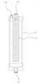
도 2는 본 고안의 일 실시예에 따른 고압의 공기를 이용한 필터형 시료 전처리 시스템의 필터모듈을 도시한 정면도.
도 3은 본 고안의 일 실시예에 따른 고압의 공기를 이용한 필터형 시료 전처리 시스템에서 시료의 전처리 과정을 도시한 회로도.
도 4는 본 고안의 일 실시예에 따른 고압의 공기를 이용한 필터형 시료 전처리 시스템에서 상수를 공급하여 소결필터를 세척하는 과정을 도시한 회로도.
도 5는 본 고안의 일 실시예에 따른 고압의 공기를 이용한 필터형 시료 전처리 시스템에서 에어를 분사하여 소결필터를 세척하는 과정을 도시한 회로도이다.1 is a circuit diagram showing a configuration of a filter type sample pretreatment system using high-pressure air according to an embodiment of the present invention;
FIG. 2 is a front view showing a filter module of a filter type sample pretreatment system using high-pressure air according to an embodiment of the present invention; FIG.
3 is a circuit diagram showing a pretreatment process of a sample in a filter type sample pretreatment system using high-pressure air according to an embodiment of the present invention.
FIG. 4 is a circuit diagram showing a process of supplying a constant water to clean a sintered filter in a filter type sample pretreatment system using high-pressure air according to an embodiment of the present invention. FIG.
FIG. 5 is a circuit diagram showing a process of cleaning a sintered filter by injecting air in a filter-type sample pretreatment system using high-pressure air according to an embodiment of the present invention.
이하, 첨부한 도면들을 참조하여 본 고안의 바람직한 실시 예들을 상세히 설명하기로 한다. 그러나, 본 고안은 여기서 설명되는 실시 예들에 한정되지 않고 다른 형태로 구체화될 수도 있다. 오히려, 여기서 소개되는 실시 예들은 개시된 내용이 철저하고 완전해질 수 있도록, 그리고 당업자에게 본 고안의 사상이 충분히 전달될 수 있도록 하기 위해 제공되는 것이다. 명세서 전체에 걸쳐서 동일한 참조번호들은 동일한 구성요소들을 나타낸다.Hereinafter, preferred embodiments of the present invention will be described in detail with reference to the accompanying drawings. However, the present invention is not limited to the embodiments described herein but may be embodied in other forms. Rather, the embodiments disclosed herein are provided so that this disclosure will be thorough and complete, and will fully convey the concept of this invention to those skilled in the art. Like reference numerals designate like elements throughout the specification.
도 1은 본 고안의 일 실시예에 따른 고압의 공기를 이용한 필터형 시료 전처리 시스템의 구성을 도시한 회로도이고, 도 2는 본 고안의 일 실시예에 따른 고압의 공기를 이용한 필터형 시료 전처리 시스템의 필터모듈을 도시한 정면도이다.FIG. 1 is a circuit diagram showing a configuration of a filter type sample preprocessing system using high-pressure air according to an embodiment of the present invention. FIG. 2 is a block diagram of a filter type sample preprocessing system using high- Fig. 3 is a front view showing the filter module of Fig.
도 1 과 도 2를 참조하면, 본 고안의 일 실시예에 따른 고압의 공기를 이용한 필터형 시료 전처리 시스템(100)은 크게 내부에 소정 공간을 형성하며, 시료에 포함된 이물질을 여과하는 소결필터(112)를 내부에 구비하는 필터모듈(110)과, 상기 필터모듈(110) 일측에 연결되며 여과할 시료를 상기 필터모듈(110) 내부로 유입시키는 시료투입라인(120)과, 상기 필터모듈(110) 타측에 연결되며, 상기 소결필터(112)에 의해 여과된 시료가 배출되는 시료배출라인(130)과, 상기 시료배출라인(130)과 연결되며, 역방향으로 상기 소결필터(112)의 세척을 위한 세척수를 공급하는 세척수분사라인(140)과, 상기 시료배출라인(130)과 연결되며, 역방향으로 상기 소결필터(112)의 세척을 위한 공기를 분사하는 에어분사라인(150)을 포함하여 이루어질 수 있다.Referring to FIGS. 1 and 2, a filter-type
상기 필터모듈(110) 내부에 설치되는 소결필터(112)는 분말야금의 고유 기공도를 활용한 고강도의 다공질 제품으로서, 요구 특성에 맞는 금속분말의 크기와 소결 기술을 적절히 조합하여 제조된다.The sintered
상기 소결필터(112)에서 여과가 이루어지는 메커니즘은 여과될 입자가 소결필터(112)의 기공을 통과하면서 소결필터(112)를 구성하고 있는 다수의 금속 분말 입자에 부딪쳐 기공 내에 쌓이게 되며 소결필터(112) 내부로 갈수록 여과될 입자수가 줄어들어 결국에는 완전한 여과에 이르게 된다.The mechanism of filtration in the
상기 소결필터(112)는 3차원의 복잡한 기공구조로 인해 2차원의 메쉬형 필터에 비해 여과효율이 매우 우수하고, 형상의 자유도가 큰 특징이 있다. 또한, 내식성이 우수하며, 고 내열성 및 강성을 갖고 있어 고온, 고압 용도에 유리한 장점이 있다.Since the
이와 같이, 본 고안의 일 실시예에 따른 고압의 공기를 이용한 필터형 시료 전처리 시스템(100)은 필터모듈(110)에 장착되는 필터로서 고압의 에어 세정에도 견딜 수 있도록 소결필터(112)를 사용하여 고압의 에어를 분사함으로써 소결필터(112)에 부착되어 있는 이물질을 순간적으로 탈리시킬 수 있다.As described above, the filter-type sample preprocessing
상기 필터모듈(110)은 내부에 중공을 갖는 원통의 외형을 가지며, 상기 소결필터(112) 또한 상기 필터모듈(110)과 같이 중공의 원통형으로 이루어질 수 있으나, 이에 한정되는 것은 아니다.The
그리고, 상기 필터모듈(110)은 하부에 시료가 유입되는 유입구(114)가 구비되고, 상부에는 상기 소결필터(112)를 통해 여과된 시료가 빠져나가는 배출구(116)가 구비될 수 있으나 상기 유입구(114)와 배출구(116)의 위치가 서로 바뀌거나 다른 위치에 구비되는 것도 가능하다.The
상기 필터모듈(110)로 투입된 시료는 상기 소결필터(112)의 외측으로부터 내측의 중공으로 투과되면서 부유물질이 여과되므로, 상기 배출구는 상기 소결필터(112)의 내측과 연통될 수 있다. 또한, 상기 필터모듈(110)의 상부 일측에는 소결필터(112) 외측과 연통되는 제1 드레인라인연결부(118)가 구비된다.Since the sample put into the
한편, 본 고안의 일 실시예에 따른 고압의 공기를 이용한 필터형 시료 전처리 시스템(100)은 여과할 시료를 상기 필터모듈(110) 내부로 유입시키는 시료투입라인(120)을 포함하여 이루어질 수 있다. 상기 시료투입라인(120)은 상기 필터모듈(110)의 일측 즉, 상기 유입구(114)와 연결되며, 투입된 시료는 시료투입라인(120)에 의해 상기 필터모듈(110)로 안내된다.Meanwhile, the filter-type sample preprocessing
상기 시료투입라인(120) 상에는 시료가 유동할 수 있도록 가압하는 투입펌프(124)와 시료투입라인(120)을 개폐하는 투입밸브(122)가 구비될 수 있다.An
상기 필터모듈(110) 타측에는 상기 소결필터(112)에 의해 여과된 시료가 배출되는 시료배출라인(130)이 연결될 수 있다. 상기 시료배출라인(130)은 배출구(116)를 통해 상기 필터모듈(110)과 연결되는데 부유물질이 제거된 시료를 측정기기(미도시)로 안내하는 역할을 수행한다.A
상기 시료배출라인(130) 상에는 여과된 시료를 임시로 저장하는 저장용기(134)가 구비될 수 있으며, 상기 시료배출라인(130)을 개폐하는 배출밸브(132)가 구비될 수 있다.A
한편, 본 고안의 일 실시예에 따른 고압의 공기를 이용한 필터형 시료 전처리 시스템(100)은 상기 시료배출라인(130)과 연결되며, 역방향으로 상기 소결필터(112)의 세척을 위한 세척수를 공급하는 세척수분사라인(140)과, 상기 시료배출라인(130)과 연결되며, 역방향으로 상기 소결필터(112)의 세척을 위한 공기를 분사하는 에어분사라인(150)을 포함하여 이루어질 수 있다.Meanwhile, the filter-type
상기 세척수분사라인(140)과 상기 에어분사라인(150)은 상기 시료배출라인(130)과 연결되며, 상기 시료배출라인(130)을 통해 상기 필터모듈(110)의 배출구(116)와 연통된다. 따라서, 상기 필터모듈(110)로 분사되는 세척수와 공기는 시료배출라인(130)을 따라 역방향으로 유동하여 상기 배출구(116)를 통해 필터모듈(110) 내부의 소결필터(112)를 세척하게 된다.The washing
본 고안의 일 실시예에 따른 고압의 공기를 이용한 필터형 시료 전처리 시스템(100)의 세척수분사라인(140)은 상수(上水)를 이용하여 세척을 수행할 수 있다.The washing
원래 세척수로 상수를 이용하면 시료측정에 영향을 줄 수 있으므로 여과된 시료를 상당량 저장해 놓았다가 이용하는 것이 일반적이지만 본 고안의 일 실시예에 따른 고압의 공기를 이용한 필터형 시료 전처리 시스템(100)은 상수로 세척을 수행한 후 에어를 분사하여 상수를 필터모듈(110)과 각 라인으로부터 깨끗이 제거하기 때문에, 상수의 이용이 가능하게 된다.The filter-type sample preprocessing
따라서, 여과된 시료를 과도하게 모아 놓음으로써 발생하는 저장용기(134)가 커지고 시료가 변질되는 문제점을 해결할 수 있다.Accordingly, it is possible to solve the problem that the
상기 세척수분사라인(140) 상에는 상수를 분사하기 위한 상수펌프(144)와 세척수분사라인(140)을 개폐하는 세척수밸브(142)가 구비될 수 있다.The washing
상기 에어분사라인(150)은 도시된 에어펌프(154) 등 압축장치를 통해 고압으로 압축된 공기를 상기 필터모듈(110)로 안내하며, 상기 에어분사라인(150)을 개폐하는 에어밸브(152)가 구비될 수 있다. 상기 에어분사라인(150)을 통해 안내되어 상기 필터모듈(110) 내부로 분사되는 공기는 고압이므로 일반 메쉬형 필터의 경우 필터의 변형이나 파손이 발생할 수 있다.The
그러나 전술한 바와 같이, 본 고안의 일 실시예에 따른 고압의 공기를 이용한 필터형 시료 전처리 시스템(100)에서는 필터모듈(110) 내부에 강성이 큰 소결필터(112)가 구비되므로, 고압으로 분사되는 공기에 의한 변형이나 파손을 방지할 수 있다.However, as described above, in the filter type sample preprocessing
여기서, 도 1에 도시된 바와 같이, 상기 세척수분사라인(140)과 에어분사라인(150)은 하나의 라인으로 합류한 후 상기 시료배출라인(130)과 연결될 수 있다.1, the washing
한편, 본 고안의 일 실시예에 따른 고압의 공기를 이용한 필터형 시료 전처리 시스템(100)은 소결필터(112)에 의해 여과되지 않고 남은 시료를 배출하는 제1 드레인라인(160)이 더 포함될 수 있다. 상기 제1 드레인라인(160)은 상기 제1 드레인라인연결부(118)를 통해 상기 필터모듈(110)과 연결되며, 시료 여과 시, 상기 소결필터(112)에 많은 압력이 걸림으로 인해 여과되지 않고 남은 시료를 배출시키는 역할을 수행한다.Meanwhile, the filter-type
상기 제1 드레인라인(160) 상에도 제1 드레인밸브(162)가 구비되어 상기 제1 드레인라인(160)을 개폐하게 된다.A
그리고, 상기 상기 시료투입라인(120)에는 상기 소결필터(112) 세척 후 이물질을 포함한 세척수를 배출하는 제2 드레인라인(170) 연결될 수 있다. 상기 시료배출라인(130)을 따라 역방향으로 필터모듈(110)의 배출구(116)를 통해 분사되어 상기 소결필터(112)를 세척한 세척수와 공기는 역시 역방향으로 상기 필터모듈(110)의 유입구를 통해 시료투입라인(120)으로 빠져나가며, 상기 시료투입라인(120)과 연결된 제2 드레인라인(170)을 통해 최종 배출된다.A
물론, 상기 제2 드레인라인(170) 상에는 제2 드레인라인(170)을 개폐하는 제2 드레인밸브(172)가 구비될 수 있다.Of course, a
한편, 본 고안의 일 실시예에 따른 고압의 공기를 이용한 필터형 시료 전처리 시스템(100)은 시료의 여과가 일정 시간 진행되면 자동으로 상기 소결필터(112)의 세척을 수행하도록 구성될 수 있다.Meanwhile, the filter-type
상기 고압의 공기를 이용한 필터형 시료 전처리 시스템(100)에 포함된 마이컴(micro-computer)으로 이루어진 제어부(미도시)는 시료 투입부터 배출까지 여과 과정을 모니터링 하며, 시료의 여과가 일정 시간 진행되어 소결필터(112)에 부유물질이 많이 끼게 되면 시료의 여과를 중지하고 소결필터(112)에 대한 세척을 진행한다.A control unit (not shown) formed of a micro-computer included in the filter-type
여기서, 세척을 수행하게 되는 시간은 시스템의 용량이나 시료의 오염도 등에 따라 달리 설정될 수 있다.Here, the time for performing the washing may be set differently depending on the capacity of the system, the degree of contamination of the sample, and the like.
또한, 본 고안의 일 실시예에 따른 고압의 공기를 이용한 필터형 시료 전처리 시스템(100)은 시료 여과 시 상기 소결필터(112)에 가해지는 압력을 측정하는 압력센서(미도시)를 더 포함하며, 상기 측정된 압력이 일정 값을 초과하는 경우 상기 소결필터(112)의 세척을 수행하도록 구성될 수 있다.In addition, the filter-type
상기 압력센서는 필터모듈(110)의 유입구(114)나 시료투입라인(120) 등에 구비될 수 있으며, 제어부에서 상기 압력센서에 의해 측정되는 압력이 일정 값 이상 되는 경우 시료의 여과를 중지하고 소결필터(112)에 대한 세척을 진행하도록 구성될 수 있다.The pressure sensor may be provided in the
여기서, 세척을 수행하게 되는 압력 값은 시스템의 용량에 따라 달리 설정될 수 있다.Here, the pressure value at which cleaning is performed may be set differently depending on the capacity of the system.
도 3은 본 고안의 일 실시예에 따른 고압의 공기를 이용한 필터형 시료 전처리 시스템에서 시료의 전처리 과정을 도시한 회로도이고, 도 4는 본 고안의 일 실시예에 따른 고압의 공기를 이용한 필터형 시료 전처리 시스템에서 상수를 공급하여 소결필터를 세척하는 과정을 도시한 회로도이며, 도 5는 본 고안의 일 실시예에 따른 고압의 공기를 이용한 필터형 시료 전처리 시스템에서 에어를 분사하여 소결필터를 세척하는 과정을 도시한 회로도이다.FIG. 3 is a circuit diagram showing a pretreatment process of a sample in a filter type sample pretreatment system using high-pressure air according to an embodiment of the present invention. FIG. FIG. 5 is a circuit diagram illustrating a process of cleaning a sintered filter by supplying a constant in a sample pretreatment system. FIG. 5 is a schematic circuit diagram illustrating a process of cleaning a sintered filter by spraying air in a filter type sample pretreatment system using high- And the like.
도 3 내지 도 5를 참조하여 본 고안의 일 실시예에 따른 고압의 공기를 이용한 필터형 시료 전처리 시스템(100)의 작동관계를 설명하면 다음과 같다.The operation of the filter-type
도 3에는 본 고안의 일 실시예에 따른 고압의 공기를 이용한 필터형 시료 전처리 시스템(100)의 시료 여과 과정에 관한 회로도가 도시되어 있다. 먼저, 상기 시료투입라인(120)을 통해 시료가 투입된다. 상기 투입밸브(122)가 개방된 상태에서 상기 투입펌프(124)가 작동하면 시료가 상기 시료투입라인(120)을 따라 필터모듈(110)의 유입구로 흘러간다. 이때, 상기 제2 드레인밸브(172)는 잠긴 상태로 유지된다.FIG. 3 is a circuit diagram illustrating a sample filtration process of the filter-type
상기 유입구(114)를 통해 필터모듈(110) 내부로 유입된 시료는 상기 소결필터(112)를 통과하며 부유물질이 제거된다. 제1 드레인밸브(162)가 오픈된 상태이므로, 소결필터(112)에 의해 여과되지 않고 남은 시료는 제1 드레인라인(160)을 통해 배출되며, 소결필터(112)에 의해 여과된 시료는 배출구(116)를 통해 시료배출라인(130)으로 배출된다.The sample introduced into the
이때, 세척과정에 사용되는 세척수분사라인(140)과 에어분사라인(150)은 각각 세척수밸브(142)와 에어밸브(152)가 잠긴 상태이고 배출밸브(132)는 오픈된 상태이다. 상기 시료배출라인(130)을 따라 안내된 시료는 저장용기(134)에 임시로 저장되며, 최종적으로 측정기기로 공급된다.At this time, the wash
도 4와 도 5에는 세척수분사 과정과 에어분사 과정이 도시되어 있다. 시료 여과 중 일정 시간이 경과하였거나 설치된 압력센서에서 측정된 압력 값이 일정 값 이상인 경우 제어부가 시료 여과를 중단하고 세척과정을 진행한다.FIGS. 4 and 5 show a washing water spraying process and an air spraying process. If a certain period of time elapses during the sample filtration or if the pressure value measured by the installed pressure sensor is more than a certain value, the control section stops the sample filtration and performs the washing process.
도 4에 도시된 바와 같이, 먼저 세척수가 분사된다. 에어밸브(152)와 배출밸브(132)가 잠긴 상태에서 세척수밸브(142)가 오픈되며, 상수펌프(144)에 의해 세척수가 세척수분사라인(140)과 시료배출라인(130)을 따라 역방향으로 안내되어 상기 필터모듈(110) 내부의 소결필터(112)로 분사된다.As shown in Fig. 4, wash water is sprayed first. The
이때, 상기 제1 드레인밸브(162)는 잠긴 상태이고 상기 제2 드레인밸브(172)는 개방 상태로서, 상기 소결필터(112)로 분사된 세척수는 유입구(114)를 통해 시료투입라인(120)을 따라 안내되며 최종적으로, 상기 제2 드레인라인(170)을 통해 배출된다.At this time, the
세척수가 소결필터(112)로 분사됨에 따라 소결필터에 부착된 부유물질의 탈리 작용이 진행되며, 이어서 도 5에 보는 바와 같이, 에어분사 과정이 진행된다.As the washing water is injected into the
세척수밸브(142)와 배출밸브(132)가 잠긴 상태에서 에어밸브(152)가 오픈되며, 에어펌프(154)에 의해 고압으로 압축된 공기가 에어분사라인(150)과 시료배출라인(130)을 따라 역방향으로 안내되어 상기 필터모듈(110) 내부의 소결필터(112)로 분사된다. 이때, 필터모듈(110) 내부에 강성이 큰 소결필터(112)가 구비되므로, 고압으로 분사되는 공기에 의한 변형이나 파손이 방지될 수 있다.The
한편, 에어분사 과정에서 상기 필터모듈(110) 내부에 세척수를 일정량 남겨놓아 에어분사에 의한 소결필터(112) 세척 효율을 더욱 좋게 할 수 있다. 따라서, 에어분사 시 일정 시간 동안은 제2 드레인밸브(172)를 제1 드레인밸브(162)와 함께 잠근 상태에서 에어분사를 실시할 수 있다.Meanwhile, in the air injection process, a certain amount of washing water is left in the
그리고, 마지막으로 상기 제1 드레인밸브(162)는 잠긴 상태에서 상기 제2 드레인밸브(172)가 개방되며, 상기 소결필터(112)로 분사된 공기와 필터모듈(110) 내에 남아있던 세척수가 유입구(114)를 통해 시료투입라인(120)을 따라 안내되어 최종적으로, 상기 제2 드레인라인(170)을 통해 배출된다.Finally, the
상기에서는 본 고안의 일 실시예를 참조하여 설명하였지만, 해당 기술분야의 당업자는 이하에서 서술하는 실용신안등록청구범위에 기재된 본 고안의 사상 및 영역으로부터 벗어나지 않는 범위 내에서 본 고안을 다양하게 수정 및 변경 실시할 수 있을 것이다. 그러므로 변형된 실시가 기본적으로 본 고안의 실용신안등록청구범위의 구성요소를 포함한다면 모두 본 고안의 기술적 범주에 포함된다고 보아야 한다.It will be apparent to those skilled in the art that various modifications and variations can be made in the present invention without departing from the spirit or scope of the invention as defined in the appended claims. Change will be possible. It is therefore to be understood that the modified embodiment basically includes all of the components of the utility model registration claims of the present invention, all of which are included in the technical category of the present invention.
100 : 시료 전처리 시스템110 : 필터모듈
112 : 소결필터120 : 시료투입라인
130 : 시료배출라인140 : 세척수분사라인
150 : 에어분사라인160 : 제1 드레인라인
170 : 제2 드레인라인100: sample preprocessing system 110: filter module
112: sintering filter 120: sample injection line
130: sample discharge line 140: wash water spray line
150: air jet line 160: first drain line
170: second drain line
Claims (4)
Translated fromKorean상기 필터모듈 일측에 연결되며 여과할 시료를 상기 필터모듈 내부로 유입시키는 시료투입라인;
상기 필터모듈 타측에 연결되며, 상기 소결필터에 의해 여과된 시료가 배출되는 시료배출라인;
상기 시료배출라인과 연결되며, 역방향으로 상기 소결필터의 세척을 위한 세척수를 공급하는 세척수분사라인;
상기 시료배출라인과 연결되며, 역방향으로 상기 소결필터의 세척을 위한 공기를 분사하는 에어분사라인;
상기 시료투입라인에 구비되고, 시료 여과 시 상기 소결필터에 가해지는 압력을 측정하는 압력센서; 및
상기 압력센서와 연결되며, 상기 측정된 압력에 따라 자동으로 운전을 제어하는 제어부를 포함하되,
상기 공기는 상기 필터모듈 내부의 세척수 존재하에 상기 에어분사라인을 따라 분사되는 것인, 고압의 공기를 이용한 필터형 시료 전처리 시스템.A filter module having a sintered filter for filtering foreign substances contained in the sample, the filter module having a predetermined space therein;
A sample injection line connected to one side of the filter module for introducing a sample to be filtered into the filter module;
A sample discharge line connected to the other side of the filter module and discharging the sample filtered by the sintered filter;
A washing water injection line connected to the sample discharge line and supplying wash water for washing the sintered filter in a reverse direction;
An air injection line connected to the sample discharge line and spraying air for washing the sintered filter in a reverse direction;
A pressure sensor provided in the sample introduction line for measuring a pressure applied to the sintered filter during sample filtration; And
And a control unit connected to the pressure sensor and automatically controlling the operation according to the measured pressure,
Wherein the air is injected along the air injection line in the presence of washing water inside the filter module.
상기 소결필터에 의해 여과되지 않고 남은 시료를 배출하는 제1 드레인라인을 더 포함하는 고압의 공기를 이용한 필터형 시료 전처리 시스템.The method according to claim 1,
And a first drain line for discharging the remaining sample without being filtered by the sintered filter.
상기 시료투입라인과 연결되며, 상기 소결필터 세척 후 이물질을 포함한 세척수를 배출하는 제2 드레인라인을 더 포함하는 고압의 공기를 이용한 필터형 시료 전처리 시스템.3. The method of claim 2,
And a second drain line connected to the sample introduction line and discharging wash water including foreign substances after cleaning the sintered filter.
시료의 여과가 일정 시간 진행되면 자동으로 상기 소결필터의 세척을 수행하는 것을 특징으로 하는 고압의 공기를 이용한 필터형 시료 전처리 시스템.The method according to claim 1,
Wherein the cleaning of the sintered filter is automatically performed when the filtration of the sample proceeds for a predetermined time.
Priority Applications (1)
| Application Number | Priority Date | Filing Date | Title |
|---|---|---|---|
| KR2020130003099UKR200475293Y1 (en) | 2013-04-22 | 2013-04-22 | filter type sample pretreatment system using high pressure air |
Applications Claiming Priority (1)
| Application Number | Priority Date | Filing Date | Title |
|---|---|---|---|
| KR2020130003099UKR200475293Y1 (en) | 2013-04-22 | 2013-04-22 | filter type sample pretreatment system using high pressure air |
Related Parent Applications (1)
| Application Number | Title | Priority Date | Filing Date |
|---|---|---|---|
| KR1020130043751Division | 2013-04-19 |
Publications (2)
| Publication Number | Publication Date |
|---|---|
| KR20130003190U KR20130003190U (en) | 2013-05-29 |
| KR200475293Y1true KR200475293Y1 (en) | 2014-11-20 |
Family
ID=52291053
Family Applications (1)
| Application Number | Title | Priority Date | Filing Date |
|---|---|---|---|
| KR2020130003099UExpired - LifetimeKR200475293Y1 (en) | 2013-04-22 | 2013-04-22 | filter type sample pretreatment system using high pressure air |
Country Status (1)
| Country | Link |
|---|---|
| KR (1) | KR200475293Y1 (en) |
Families Citing this family (5)
| Publication number | Priority date | Publication date | Assignee | Title |
|---|---|---|---|---|
| KR102196493B1 (en)* | 2020-04-16 | 2020-12-29 | 유니젠바이오 주식회사 | CTCs ANALYSIS SYSTEM FOR DIAGNOSING CANCER |
| KR102177222B1 (en)* | 2020-04-24 | 2020-11-10 | 유니젠바이오 주식회사 | System for predicting cancer diagnosis based on machine learning |
| KR102177226B1 (en)* | 2020-04-24 | 2020-11-10 | 유니젠바이오 주식회사 | Amplifiaction apparatus for polymerase chain reaction |
| KR102177218B1 (en)* | 2020-04-24 | 2020-11-10 | 유니젠바이오 주식회사 | Apparatus for predicting cancer diagnosis based on machine learning |
| KR102197410B1 (en)* | 2020-04-24 | 2020-12-31 | 유니젠바이오 주식회사 | Monitoring system for nucleic acid amplification reaction |
Citations (1)
| Publication number | Priority date | Publication date | Assignee | Title |
|---|---|---|---|---|
| JP2009142746A (en)* | 2007-12-13 | 2009-07-02 | Dkk Toa Corp | Filtration device, filter and filtration method |
- 2013
- 2013-04-22KRKR2020130003099Upatent/KR200475293Y1/ennot_activeExpired - Lifetime
Patent Citations (1)
| Publication number | Priority date | Publication date | Assignee | Title |
|---|---|---|---|---|
| JP2009142746A (en)* | 2007-12-13 | 2009-07-02 | Dkk Toa Corp | Filtration device, filter and filtration method |
Also Published As
| Publication number | Publication date |
|---|---|
| KR20130003190U (en) | 2013-05-29 |
Similar Documents
| Publication | Publication Date | Title |
|---|---|---|
| KR200475293Y1 (en) | filter type sample pretreatment system using high pressure air | |
| US10661205B2 (en) | Filter cleaning system and method | |
| CN102905769B (en) | Process for filtration of fluids and filter apparatus for performing the process | |
| CN102698484A (en) | Full-automatic filter cake layer filter and filtering method thereof | |
| US20140263106A1 (en) | Filtration system and method | |
| CN103331052A (en) | Filter bag cleaning device | |
| CN105642118B (en) | It is a kind of for the automatic backwash water purification system of backwashing water purification apparatus and its purging method | |
| CN103768852A (en) | backwash filter | |
| KR20120079599A (en) | Filter type sample pretreatment system using high pressure air | |
| JP5768391B2 (en) | Filtration device | |
| JP2017006876A (en) | Filter device and filter cleaning method of filter device | |
| KR102041612B1 (en) | Water treatment system capable of filter washing | |
| JP2008284464A (en) | Filtering method and apparatus therefor with excellent intermittent backwashing | |
| KR101071521B1 (en) | Spray Header Vacuum Cleaner for Cold Rolling Plating Equipment | |
| JP4614370B2 (en) | Backwash filter | |
| KR101997503B1 (en) | Filtering system for removing fine dust and noxious gas synchronously | |
| US7959798B2 (en) | Device for treating a back-flushed fluid | |
| JP4953806B2 (en) | Filtration device | |
| KR20070096798A (en) | Reverse osmosis device | |
| CN209630771U (en) | A kind of machine tool intelligence system based on Internet of Things | |
| KR101345261B1 (en) | Filtering apparatus without back wash | |
| JP7274801B2 (en) | Pneumatic-Hydraulic Backwash Process and Apparatus for Backflushing Fluid Filters with Integrated Fluid Dynamic Cleaning Process | |
| CN102989224A (en) | Full-automatic slag removal filter | |
| CN212039187U (en) | Filter device | |
| JP6928635B2 (en) | Filtration device and filter cleaning method for filtration device |
Legal Events
| Date | Code | Title | Description |
|---|---|---|---|
| A201 | Request for examination | ||
| UA0105 | Converted application for utility model registration | Patent event date:20130422 Patent event code:UA01011R05D Comment text:Application for Conversion into Application for Utility Model Registration | |
| UA0201 | Request for examination | ||
| UG1501 | Laying open of application | ||
| E902 | Notification of reason for refusal | ||
| UE0902 | Notice of grounds for rejection | Comment text:Notification of reason for refusal Patent event code:UE09021S01D Patent event date:20140211 | |
| E701 | Decision to grant or registration of patent right | ||
| UE0701 | Decision of registration | Patent event date:20140813 Comment text:Decision to Grant Registration Patent event code:UE07011S01D | |
| REGI | Registration of establishment | ||
| UR0701 | Registration of establishment | Patent event date:20141113 Patent event code:UR07011E01D Comment text:Registration of Establishment | |
| UR1002 | Payment of registration fee | Start annual number:1 End annual number:3 Payment date:20141114 | |
| UG1601 | Publication of registration | ||
| FPAY | Annual fee payment | Payment date:20171113 Year of fee payment:4 | |
| UR1001 | Payment of annual fee | Payment date:20171113 Start annual number:4 End annual number:4 | |
| FPAY | Annual fee payment | Payment date:20181113 Year of fee payment:5 | |
| UR1001 | Payment of annual fee | Payment date:20181113 Start annual number:5 End annual number:5 | |
| FPAY | Annual fee payment | Payment date:20191112 Year of fee payment:6 | |
| UR1001 | Payment of annual fee | Payment date:20191112 Start annual number:6 End annual number:6 | |
| UR1001 | Payment of annual fee | Payment date:20201111 Start annual number:7 End annual number:7 | |
| UC1801 | Expiration of term | Termination category:Expiration of duration Termination date:20210705 |