KR200465456Y1 - Rear Camera for Vehicle - Google Patents
Rear Camera for VehicleDownload PDFInfo
- Publication number
- KR200465456Y1 KR200465456Y1KR2020110006971UKR20110006971UKR200465456Y1KR 200465456 Y1KR200465456 Y1KR 200465456Y1KR 2020110006971 UKR2020110006971 UKR 2020110006971UKR 20110006971 UKR20110006971 UKR 20110006971UKR 200465456 Y1KR200465456 Y1KR 200465456Y1
- Authority
- KR
- South Korea
- Prior art keywords
- camera
- vehicle
- led module
- housing
- rear camera
- Prior art date
- Legal status (The legal status is an assumption and is not a legal conclusion. Google has not performed a legal analysis and makes no representation as to the accuracy of the status listed.)
- Expired - Fee Related
Links
Images

Classifications
- B—PERFORMING OPERATIONS; TRANSPORTING
- B60—VEHICLES IN GENERAL
- B60R—VEHICLES, VEHICLE FITTINGS, OR VEHICLE PARTS, NOT OTHERWISE PROVIDED FOR
- B60R11/00—Arrangements for holding or mounting articles, not otherwise provided for
- B60R11/04—Mounting of cameras operative during drive; Arrangement of controls thereof relative to the vehicle
- B—PERFORMING OPERATIONS; TRANSPORTING
- B60—VEHICLES IN GENERAL
- B60R—VEHICLES, VEHICLE FITTINGS, OR VEHICLE PARTS, NOT OTHERWISE PROVIDED FOR
- B60R2300/00—Details of viewing arrangements using cameras and displays, specially adapted for use in a vehicle
- B60R2300/80—Details of viewing arrangements using cameras and displays, specially adapted for use in a vehicle characterised by the intended use of the viewing arrangement
- B60R2300/8046—Details of viewing arrangements using cameras and displays, specially adapted for use in a vehicle characterised by the intended use of the viewing arrangement for replacing a rear-view mirror system
- B—PERFORMING OPERATIONS; TRANSPORTING
- B60—VEHICLES IN GENERAL
- B60R—VEHICLES, VEHICLE FITTINGS, OR VEHICLE PARTS, NOT OTHERWISE PROVIDED FOR
- B60R2300/00—Details of viewing arrangements using cameras and displays, specially adapted for use in a vehicle
- B60R2300/80—Details of viewing arrangements using cameras and displays, specially adapted for use in a vehicle characterised by the intended use of the viewing arrangement
- B60R2300/8053—Details of viewing arrangements using cameras and displays, specially adapted for use in a vehicle characterised by the intended use of the viewing arrangement for bad weather conditions or night vision
Landscapes
- Engineering & Computer Science (AREA)
- Mechanical Engineering (AREA)
- Studio Devices (AREA)
Abstract
Translated fromKoreanDescription
Translated fromKorean본 고안은 후방카메라에 관한 것으로, 보다 상세하게는 엘이디(LED) 모듈을 사용하는 차량용 후방카메라에 관한 것이다.
The present invention relates to a rear camera, and more particularly to a rear camera for a vehicle using an LED (LED) module.
현재 차량의 사각지대인 후방을 식별하는 방법은 룸미러와 사이드미러 등을 이용하는 것과 더 편리하게 식별하기 위한 방법으로 후방카메라 등과 같은 장비들로 촬영하고 이를 차량 내부의 모니터를 통해 차량 후방을 볼 수 있는 것이 현재의 모습이다.The method of identifying the rear of the blind spot of the current vehicle is to use the room mirror and the side mirror, and to identify the rear side of the vehicle more conveniently, the camera can be photographed with equipment such as the rear camera and the rear of the vehicle can be viewed through the monitor inside the vehicle. It is present.
종래의 후방카메라를 사용하면 후진 주행을 할 시 주간에는 별 다른 장비 없이 사용 가능하며 야간에는 후진등을 이용해야 한다. 하지만 후방카메라에 사용되는 센서의 특성상 야간에는 차량 내부에 위치한 모니터에 영상 노이즈가 일어나며 후방을 식별하는데 문제점이 발생하기 때문에 후방카메라 근처 부분에 조명을 장착하여 사용하는 것이 일반적이며 또는 후진등보다 조도가 높은 조명을 사용한다. 하지만 이 경우에도 발광 각도가 넓어 빛이 멀리 나아가지 않기 때문에 해결책이 되지 못하므로 같은 어려움을 겪게 된다.
If you use a conventional rear camera, you can use it without any equipment during the day when driving backwards and use a reverse light at night. However, due to the characteristics of the sensor used in the rear camera, it is common to use the lighting near the rear camera because the image noise occurs on the monitor located inside the vehicle at night, and there is a problem in identifying the rear. Use high light. However, even in this case, since the light emission angle is wide and light does not go far, it is not a solution, and thus suffers from the same difficulty.
상기한 종래 문제점을 해결하기 위한 본 고안의 목적은 야간에 후방카메라 사용시 발광 각도를 좁혀 빛이 멀리 나가도록 엘이디(LED) 상부에 렌즈를 장착한 차량용 후방카메라를 제공하는데 있다.
An object of the present invention for solving the above-mentioned problems is to provide a rear camera for a vehicle equipped with a lens on the LED (LED) so that the light goes out to narrow the light emission angle when using the rear camera at night.
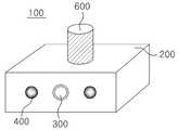
상기한 종래 문제점을 해결하고 상기 목적을 달성하기 위한 본 고안의 실시 예에 따른 차량용 후방카메라(100)는, 하우징과; 상기 하우징(200) 내부에 차량의 후방을 촬영하는 카메라(300)와; 상기 카메라(300) 주위에 위치하는 엘이디모듈(400)과; 상기 하우징(200) 내부에 카메라(300) 및 엘이디모듈(400)의 동작제어와 카메라(400)가 촬영한 영상 신호를 모니터로 전송하는 제어부(500); 및 상기 차량과 하우징(200)을 결합하는 결합부(600);를 포함하되,The
상기 엘이디모듈(400)은 엘이디(410) 상부에 빛의 발광각도를 줄여주는 렌즈(420)를 포함하는 것을 특징으로 한다.The
본 고안의 실시 예에 따른 차량용 후방카메라에 있어서, 상기 엘이디모듈(400)은 카메라(300) 측면에 적어도 하나 이상을 배치하고, 바람직하게는 상기 카메라(300) 좌우에 배치하는 것을 특징으로 한다.In the vehicle rear camera according to an embodiment of the present invention, the
본 고안의 실시 예에 따른 차량용 후방카메라에 있어서, 상기 엘이디모듈(400)과 제어부(500)를 연결하는 연결부(430)를 더 포함하는 것을 특징으로 한다.In the vehicle rear camera according to an embodiment of the present invention, it characterized in that it further comprises a
본 고안의 실시 예에 따른 차량용 후방카메라에 있어서, 상기 결합부(600)는 차량과의 결합을 위해 나선형상으로 구현하며, 차량 내부의 모니터에 영상 신호를 보낼 수 있는 라인을 포함하는 것을 특징으로 한다.
In the vehicle rear camera according to an embodiment of the present invention, the
상기한 바와 같이, 본 고안의 실시 예에 따른 후방카메라는 엘이디(LED)모듈에 발광각도를 좁혀주는 렌즈를 장착하므로 빛이 나아가는 범위가 늘어나 야간에 후방카메라가 촬영하는 모습을 나타내는 모니터에 영상 노이즈가 없어지고, 후진 주행 시에 안정적인 운행을 할 수 있는 효과가 있다.As described above, the rear camera according to the embodiment of the present invention is equipped with a lens that narrows the light emitting angle to the LED (LED) module, so that the range of light is increased, the image noise on the monitor showing the appearance of the rear camera at night There is no effect, there is an effect that can be stable driving in the reverse driving.
또한 자동차 후방에 있는 사물의 확실한 식별과 사람이나 동물 등에 경고성 메시지를 주어 사고예방에 큰 도움을 주는 효과가 있다.
In addition, it gives a clear identification of objects in the rear of the car and gives warning messages to people or animals, which is very helpful in preventing accidents.
도 1은 본 고안의 실시 예에 따른 차량용 후방카메라를 나타낸 도면이다.
도 2는 본 고안의 엘이디(LED) 모듈을 나타낸 도면이다.1 is a view showing a vehicle rear camera according to an embodiment of the present invention.
2 is a view showing an LED (LED) module of the present invention.
이하, 첨부된 도면을 참조하여 본 고안에 따른 구체적인 실시 예를 상세하게 설명하면 다음과 같다.Hereinafter, exemplary embodiments of the present invention will be described in detail with reference to the accompanying drawings.
도 1은 본 고안의 실시 예에 따른 차량용 후방카메라를 나타낸 도면이다.1 is a view showing a vehicle rear camera according to an embodiment of the present invention.
도 1에 도시된 바와 같이, 본 고안의 차량용 후방카메라(100)는 하우징(200)과 카메라(300), 엘이디모듈(400), 제어부(500) 및 결합부(600)으로 구성한다.As shown in FIG. 1, the vehicle
먼저, 하우징(200)은 외형적으로 육면체 형태이고 내부에 결합 공간을 포함하며 내부 중앙에는 카메라(300)가 위치한다.First, the
여기에서 카메라(300)는 차량의 후방 영상을 취득하여 차량 내부에 장착되어 있는 모니터로 전송한다. 이때, 야간 주행 시 후방의 영상을 얻기 위해 하우징(200)의 카메라(300)가 위치한 면에 적어도 하나 이상의 엘이디 모듈(400)을 배치하고, 바람직하게는 카메라(300)의 좌, 우측에 배치한다.Here, the
이하 엘이디모듈(400)에 대하여 상세하게 설명하면 다음과 같다.Hereinafter, the
도 2는 본 고안의 엘이디모듈(400)을 나타낸 도면이다.2 is a view showing the
도 2에 도시된 바와 같이, 엘이디모듈(400)은 빛을 내는 광원의 발광각도를 줄여서 빛이 멀리 나아가게 하기 위하여 엘이디(410) 및 렌즈(420)와 연결부(430)로 구성한다.As shown in FIG. 2, the
이때 광원은 후진등보다 조도가 높은 엘이디(410)를 사용하며 발광각도를 줄이기 위해 빛을 모을 수 있는 볼록렌즈의 형태로 이루어진 렌즈(420)를 엘이디(410) 상부에 배치하며, 엘이디(410)와 제어부(500)는 연결부(430)를 통해 연결한다.In this case, the light source uses an
여기에서 엘이디(410)를 상기 렌즈(420) 없이 사용할 경우 발광 각도가 180°이기 때문에 빛이 멀리 나아가지 못하므로 상기 렌즈(420)를 사용해 발광각도를 110°~130°로 줄이게 됨으로써 빛이 나아가는 거리가 늘어나며 빛이 없는 야간에도 종래의 기술들 보다 깨끗한 영상을 얻게 된다.In this case, when the
여기에서 제어부(500)는 카메라(300)와 엘이디모듈(400)을 제어하며, 또한 촬영된 영상 신호를 유선일 경우에는 결합부(600)의 라인을 통해 모니터로 전송하며 무선일 경우에는 내장되어 있는 송신기를 통해 모니터로 전송한다.Herein, the
상기 결합부(600)는 후방카메라(100)를 차량에 누구나 쉽게 결합 할 수 있도록 나선형태로 구현되어 있다.The
이때, 상기 결합부(600)는 하우징(200)의 상부, 하부 또는 측면, 후방 부분에 위치시키는 것이 가능하고, 차량 내부의 모니터에 영상 신호를 보낼 수 있는 라인이 포함되어 있다.In this case, the
이상에서 설명한 바와 같이, 본 고안의 상세한 설명에서는 본 고안의 바람직한 실시 예에 관하여 설명하였으나, 본 고안이 속하는 기술분야에서 통상의 지식을 가진 자라면 본 고안의 범주에서 벗어나지 않는 한도 내에서 여러 가지 변형이 가능함은 물론이다. 따라서 본 고안의 권리 범위는 설명된 실시 예에 국한되어 정해져서는 안되며, 후술하는 청구범위뿐만 아니라, 이와 균등한 것들에 의해 정해져야 한다.
As described above, in the detailed description of the present invention has been described with respect to the preferred embodiment of the present invention, those skilled in the art to which the present invention belongs to various modifications without departing from the scope of the present invention Of course this is possible. Therefore, the scope of the present invention should not be limited to the embodiments described, but should be determined by the equivalents thereof, as well as the claims described below.
100 : 후방카메라 200 : 하우징
300 : 카메라 400 : 엘이디(LED)모듈
500 : 제어부 600 : 결합부100: rear camera 200: housing
300: camera 400: LED module
500
Claims (4)
Translated fromKorean하우징과;
상기 하우징(200) 내부에 차량의 후방을 촬영하는 카메라(300)와;
상기 카메라(300) 주위에 위치하는 엘이디모듈(400)과;
상기 하우징(200) 내부에 카메라(300) 및 엘이디모듈(400)의 동작제어와 카메라(400)가 촬영한 영상 신호를 모니터로 전송하는 제어부(500); 및
상기 차량과 하우징(200)을 결합하는 결합부(600);를 포함하되,
상기 엘이디모듈(400)은 엘이디(410) 상부에 빛의 발광각도를 줄여주는 렌즈(420)를 포함하는 것을 특징으로 하는 차량용 후방카메라.
In the vehicle rear camera,
A housing;
A camera (300) for photographing the rear of the vehicle in the housing (200);
An LED module 400 positioned around the camera 300;
A control unit 500 for controlling the operation of the camera 300 and the LED module 400 and transmitting an image signal captured by the camera 400 to a monitor in the housing 200; And
Includes; coupling portion 600 for coupling the vehicle and the housing 200,
The LED module 400 is a rear camera for a vehicle, characterized in that it comprises a lens (420) to reduce the light emitting angle of light on the LED (410).
상기 엘이디모듈(400)은 카메라(300) 측면에 적어도 하나 이상을 배치하는 것을 특징으로 하는 차량용 후방카메라.
The method of claim 1,
The LED module 400 is at least one vehicle rear camera, characterized in that disposed at the side of the camera (300).
상기 엘이디모듈(400)과 제어부(500)를 연결하는 연결부(430)를 더 포함하는 것을 특징으로 하는 차량용 후방카메라.
The method of claim 1,
Vehicle rear camera, characterized in that further comprising a connection unit 430 for connecting the LED module 400 and the control unit 500.
상기 결합부(600)는 차량과의 결합을 위해 나선형상으로 구현하며, 차량 내부의 모니터에 영상 신호를 보낼 수 있는 라인을 포함하는 것을 특징으로 하는 차량용 후방카메라.
The method of claim 1,
The coupling unit 600 is implemented in a spiral shape for coupling with the vehicle, the vehicle rear camera, characterized in that it comprises a line for sending an image signal to the monitor inside the vehicle.
Priority Applications (1)
| Application Number | Priority Date | Filing Date | Title |
|---|---|---|---|
| KR2020110006971UKR200465456Y1 (en) | 2011-08-01 | 2011-08-01 | Rear Camera for Vehicle |
Applications Claiming Priority (1)
| Application Number | Priority Date | Filing Date | Title |
|---|---|---|---|
| KR2020110006971UKR200465456Y1 (en) | 2011-08-01 | 2011-08-01 | Rear Camera for Vehicle |
Publications (2)
| Publication Number | Publication Date |
|---|---|
| KR20130000955U KR20130000955U (en) | 2013-02-12 |
| KR200465456Y1true KR200465456Y1 (en) | 2013-02-21 |
Family
ID=51360131
Family Applications (1)
| Application Number | Title | Priority Date | Filing Date |
|---|---|---|---|
| KR2020110006971UExpired - Fee RelatedKR200465456Y1 (en) | 2011-08-01 | 2011-08-01 | Rear Camera for Vehicle |
Country Status (1)
| Country | Link |
|---|---|
| KR (1) | KR200465456Y1 (en) |
Families Citing this family (1)
| Publication number | Priority date | Publication date | Assignee | Title |
|---|---|---|---|---|
| KR102301884B1 (en)* | 2018-12-21 | 2021-09-15 | 주) 플러스텍 | Line scan camera system |
Citations (2)
| Publication number | Priority date | Publication date | Assignee | Title |
|---|---|---|---|---|
| KR20090030973A (en)* | 2007-09-21 | 2009-03-25 | 주식회사 인스모바일 | Vehicle rear surveillance camera fixed structure and camera system having same |
| KR20110090958A (en)* | 2008-10-28 | 2011-08-10 | 코닌클리케 필립스 일렉트로닉스 엔.브이. | Generation of occlusion data for image attributes |
- 2011
- 2011-08-01KRKR2020110006971Upatent/KR200465456Y1/ennot_activeExpired - Fee Related
Patent Citations (2)
| Publication number | Priority date | Publication date | Assignee | Title |
|---|---|---|---|---|
| KR20090030973A (en)* | 2007-09-21 | 2009-03-25 | 주식회사 인스모바일 | Vehicle rear surveillance camera fixed structure and camera system having same |
| KR20110090958A (en)* | 2008-10-28 | 2011-08-10 | 코닌클리케 필립스 일렉트로닉스 엔.브이. | Generation of occlusion data for image attributes |
Also Published As
| Publication number | Publication date |
|---|---|
| KR20130000955U (en) | 2013-02-12 |
Similar Documents
| Publication | Publication Date | Title |
|---|---|---|
| US8830324B2 (en) | Vehicle monitoring camera and vehicle monitoring camera system | |
| CN105008179B (en) | lighting control device | |
| US20190007142A1 (en) | Light identification transmission device and light identification communication system | |
| CN111103631A (en) | Concealed camera detection camera and detection method thereof | |
| WO2015072133A1 (en) | Lamp unit | |
| ITMO20130012A1 (en) | DEVICE FOR ASSISTANCE TO THE MOTOR VEHICLE GUIDE | |
| JP2015043279A (en) | Night vision device for vehicles | |
| JP4751443B2 (en) | Imaging apparatus and imaging method | |
| US20120039592A1 (en) | Video camera supplementary white light control method | |
| KR200455913Y1 (en) | Multi-camera with illumination device | |
| KR200465456Y1 (en) | Rear Camera for Vehicle | |
| KR200475866Y1 (en) | An angle control type skirt module | |
| JP2006332288A (en) | LED light source for in-vehicle surveillance camera lighting | |
| US11245829B2 (en) | Communication device of a motor vehicle, a motor vehicle lighting device for the communication device of a motor vehicle and a Car2Car or Car2X communication method for a motor vehicle | |
| JP6322723B2 (en) | Imaging apparatus and vehicle | |
| TW201909134A (en) | Street lamp with remote monitoring function including a street lamp body which is provided with a monitoring unit, a lighting unit, a control unit, and a transmitting device | |
| KR200477863Y1 (en) | Parking Camera | |
| CN204350123U (en) | A high-definition network red-exposure laser pan-tilt camera device | |
| KR20130097851A (en) | Led lighting apparatus having vision function and system as the same | |
| KR101637159B1 (en) | surveillance camera | |
| KR20150143143A (en) | Wearable device and lighting systerm includes the wearable device | |
| JP7507433B2 (en) | Lighting Systems and Control Devices | |
| US20240161617A1 (en) | Three-way parking control camera apparatus with parking space displaying function | |
| US7593056B2 (en) | Infrared vision illumination enhancement | |
| TWI614154B (en) | Intelligent light source control system |
Legal Events
| Date | Code | Title | Description |
|---|---|---|---|
| A201 | Request for examination | ||
| UA0108 | Application for utility model registration | St.27 status event code:A-0-1-A10-A12-nap-UA0108 | |
| UA0201 | Request for examination | St.27 status event code:A-1-2-D10-D11-exm-UA0201 | |
| N231 | Notification of change of applicant | ||
| UN2301 | Change of applicant | St.27 status event code:A-3-3-R10-R13-asn-UN2301 St.27 status event code:A-3-3-R10-R11-asn-UN2301 | |
| P11-X000 | Amendment of application requested | St.27 status event code:A-2-2-P10-P11-nap-X000 | |
| P13-X000 | Application amended | St.27 status event code:A-2-2-P10-P13-nap-X000 | |
| E902 | Notification of reason for refusal | ||
| UE0902 | Notice of grounds for rejection | St.27 status event code:A-1-2-D10-D21-exm-UE0902 | |
| P11-X000 | Amendment of application requested | St.27 status event code:A-2-2-P10-P11-nap-X000 | |
| P13-X000 | Application amended | St.27 status event code:A-2-2-P10-P13-nap-X000 | |
| E701 | Decision to grant or registration of patent right | ||
| UE0701 | Decision of registration | St.27 status event code:A-1-2-D10-D22-exm-UE0701 | |
| UG1501 | Laying open of application | St.27 status event code:A-1-1-Q10-Q12-nap-UG1501 | |
| REGI | Registration of establishment | ||
| UR0701 | Registration of establishment | St.27 status event code:A-2-4-F10-F11-exm-UR0701 | |
| UR1002 | Payment of registration fee | St.27 status event code:A-2-2-U10-U11-oth-UR1002 Fee payment year number:1 | |
| UG1601 | Publication of registration | St.27 status event code:A-4-4-Q10-Q13-nap-UG1601 | |
| LAPS | Lapse due to unpaid annual fee | ||
| UC1903 | Unpaid annual fee | St.27 status event code:A-4-4-U10-U13-oth-UC1903 Not in force date:20160215 Payment event data comment text:Termination Category : DEFAULT_OF_REGISTRATION_FEE | |
| UC1903 | Unpaid annual fee | St.27 status event code:N-4-6-H10-H13-oth-UC1903 Ip right cessation event data comment text:Termination Category : DEFAULT_OF_REGISTRATION_FEE Not in force date:20160215 | |
| P22-X000 | Classification modified | St.27 status event code:A-4-4-P10-P22-nap-X000 | |
| P22-X000 | Classification modified | St.27 status event code:A-4-4-P10-P22-nap-X000 |