KR200460461Y1 - Charging apparatus for vaporizing and inhaling apparatus - Google Patents
Charging apparatus for vaporizing and inhaling apparatusDownload PDFInfo
- Publication number
- KR200460461Y1 KR200460461Y1KR2020090012857UKR20090012857UKR200460461Y1KR 200460461 Y1KR200460461 Y1KR 200460461Y1KR 2020090012857 UKR2020090012857 UKR 2020090012857UKR 20090012857 UKR20090012857 UKR 20090012857UKR 200460461 Y1KR200460461 Y1KR 200460461Y1
- Authority
- KR
- South Korea
- Prior art keywords
- charging
- charging device
- vaporization suction
- suction device
- rechargeable battery
- Prior art date
- Legal status (The legal status is an assumption and is not a legal conclusion. Google has not performed a legal analysis and makes no representation as to the accuracy of the status listed.)
- Expired - Fee Related
Links
Images


Classifications
- A—HUMAN NECESSITIES
- A24—TOBACCO; CIGARS; CIGARETTES; SIMULATED SMOKING DEVICES; SMOKERS' REQUISITES
- A24F—SMOKERS' REQUISITES; MATCH BOXES; SIMULATED SMOKING DEVICES
- A24F15/00—Receptacles or boxes specially adapted for cigars, cigarettes, simulated smoking devices or cigarettes therefor
- A24F15/01—Receptacles or boxes specially adapted for cigars, cigarettes, simulated smoking devices or cigarettes therefor specially adapted for simulated smoking devices or cigarettes therefor
- A24F15/015—Receptacles or boxes specially adapted for cigars, cigarettes, simulated smoking devices or cigarettes therefor specially adapted for simulated smoking devices or cigarettes therefor with means for refilling of liquid inhalable precursors
- A—HUMAN NECESSITIES
- A24—TOBACCO; CIGARS; CIGARETTES; SIMULATED SMOKING DEVICES; SMOKERS' REQUISITES
- A24B—MANUFACTURE OR PREPARATION OF TOBACCO FOR SMOKING OR CHEWING; TOBACCO; SNUFF
- A24B15/00—Chemical features or treatment of tobacco; Tobacco substitutes, e.g. in liquid form
- A24B15/10—Chemical features of tobacco products or tobacco substitutes
- A24B15/16—Chemical features of tobacco products or tobacco substitutes of tobacco substitutes
- A24B15/167—Chemical features of tobacco products or tobacco substitutes of tobacco substitutes in liquid or vaporisable form, e.g. liquid compositions for electronic cigarettes
- A—HUMAN NECESSITIES
- A24—TOBACCO; CIGARS; CIGARETTES; SIMULATED SMOKING DEVICES; SMOKERS' REQUISITES
- A24F—SMOKERS' REQUISITES; MATCH BOXES; SIMULATED SMOKING DEVICES
- A24F40/00—Electrically operated smoking devices; Component parts thereof; Manufacture thereof; Maintenance or testing thereof; Charging means specially adapted therefor
- A24F40/10—Devices using liquid inhalable precursors
- A—HUMAN NECESSITIES
- A61—MEDICAL OR VETERINARY SCIENCE; HYGIENE
- A61M—DEVICES FOR INTRODUCING MEDIA INTO, OR ONTO, THE BODY; DEVICES FOR TRANSDUCING BODY MEDIA OR FOR TAKING MEDIA FROM THE BODY; DEVICES FOR PRODUCING OR ENDING SLEEP OR STUPOR
- A61M15/00—Inhalators
- A61M15/06—Inhaling appliances shaped like cigars, cigarettes or pipes
- H—ELECTRICITY
- H02—GENERATION; CONVERSION OR DISTRIBUTION OF ELECTRIC POWER
- H02J—CIRCUIT ARRANGEMENTS OR SYSTEMS FOR SUPPLYING OR DISTRIBUTING ELECTRIC POWER; SYSTEMS FOR STORING ELECTRIC ENERGY
- H02J7/00—Circuit arrangements for charging or depolarising batteries or for supplying loads from batteries
- H02J7/0042—Circuit arrangements for charging or depolarising batteries or for supplying loads from batteries characterised by the mechanical construction
- H02J7/0044—Circuit arrangements for charging or depolarising batteries or for supplying loads from batteries characterised by the mechanical construction specially adapted for holding portable devices containing batteries
- H—ELECTRICITY
- H02—GENERATION; CONVERSION OR DISTRIBUTION OF ELECTRIC POWER
- H02J—CIRCUIT ARRANGEMENTS OR SYSTEMS FOR SUPPLYING OR DISTRIBUTING ELECTRIC POWER; SYSTEMS FOR STORING ELECTRIC ENERGY
- H02J7/00—Circuit arrangements for charging or depolarising batteries or for supplying loads from batteries
- H02J7/02—Circuit arrangements for charging or depolarising batteries or for supplying loads from batteries for charging batteries from AC mains by converters
Landscapes
- Engineering & Computer Science (AREA)
- Health & Medical Sciences (AREA)
- Power Engineering (AREA)
- Anesthesiology (AREA)
- Heart & Thoracic Surgery (AREA)
- Chemical Kinetics & Catalysis (AREA)
- Bioinformatics & Cheminformatics (AREA)
- Pulmonology (AREA)
- Chemical & Material Sciences (AREA)
- Biomedical Technology (AREA)
- General Chemical & Material Sciences (AREA)
- Hematology (AREA)
- Life Sciences & Earth Sciences (AREA)
- Animal Behavior & Ethology (AREA)
- General Health & Medical Sciences (AREA)
- Public Health (AREA)
- Veterinary Medicine (AREA)
- Charge And Discharge Circuits For Batteries Or The Like (AREA)
Abstract
Translated fromKoreanDescription
Translated fromKorean본 고안은 기화 흡입 장치용 충전 장치에 관한 것이다.The present invention relates to a charging device for a vaporization suction device.
기화 흡입 장치는 내부에 소정의 기화 대상체를 함유한 필터를 내장하여, 그 필터 내의 기화 대상체를 기화기를 통해 기화시켜 사용자가 흡입할 수 있도록 하는 장치이다.The vaporization suction device is a device having a filter containing a predetermined vaporization object therein, and vaporizing the vaporization object in the filter through a vaporizer so that a user can inhale.
이러한 기화 흡입 장치 내에는 니코틴 액, 건강 보조 성분이 함유된 액체 등의 기화 대상체가 수용될 수 있다. 그 대표적인 기화 흡입 장치로는 내부에 니코틴 액을 수용한 전자 담배가 있다.The vaporization inhalation device may contain a vaporization object such as a nicotine liquid, a liquid containing a health supplement component, and the like. A typical vaporization suction device is an electronic cigarette containing nicotine liquid inside.
최근 금연 보조용으로 담배 잎 가루를 종이로 말아놓은 실제 담배와 유사한 전자 담배의 이용이 늘어나고 있다.Recently, the use of electronic cigarettes similar to real cigarettes, which are made of paper dusted tobacco leaf powder, is increasing.
사용자가 실제 담배를 피울 때처럼 전자 담배를 입에 물고 흡입을 하게 되면, 전자 담배의 노출된 말단에서는 실제 담배에서 발생되는 불꽃과 유사한 불빛이 발생되고, 전자 담배의 사용자 입 내부의 말단에서는 실제 담배에서 발생되는 연기와 유사한 연기가 발생된다. 따라서, 이러한 전자 담배를 이용하면, 사용자는 실제 담배를 피우는 것과 유사한 느낌을 가질 수 있게 된다.If the user inserts the electronic cigarette into the mouth and sucks the same as when the user actually feels smoking, the exposed end of the electronic cigarette produces a light similar to that of a real cigarette, A smoke similar to the smoke generated in the combustion chamber is generated. Therefore, using such an electronic cigarette, the user can feel similar to the actual smoking.
일반적으로 전자 담배는 다수 개의 부재로 분할되고, 그 부재 중 제일 앞쪽의 부재 내에 발광 다이오드, 충전지, 회로 기판 및 흡입 감지 스위치가 수용되고, 그 다음 부재 내에 연기 제조 장치가 수용되며, 그 다음 부재 내에 니코틴 액을 함유한 필터가 수용된다. 이러한 전자 담배의 일 예로, 본원의 출원 전인 2009년 04월 02일에 공개된 특허공개번호 제10-2009-0033311호가 있다.In general, the electronic cigarette is divided into a plurality of members, in which the light emitting diode, the rechargeable battery, the circuit board and the suction detection switch are accommodated in the first member, and then the smoke manufacturing apparatus is received in the member, and then in the member. Filters containing nicotine liquid are accommodated. An example of such an electronic cigarette is Patent Publication No. 10-2009-0033311 published on April 02, 2009, before the application of the present application.
이러한 전자 담배 등 기화 흡입 장치는 그 내부에 수용된 충전지에 의해 구동되므로, 주기적으로 충전지를 충전시켜 주어야 하는데, 이러한 기화 흡입 장치의 충전지를 충전시키는 장치가 기화 흡입 장치용 충전 장치이다.Since the vaporization suction device such as an electronic cigarette is driven by a rechargeable battery housed therein, the rechargeable battery should be charged periodically. A device for charging the rechargeable battery of the vaporization suction device is a charging device for a vaporization suction device.
기화 흡입 장치용 충전 장치에서는 외부 전원과 연결되어 충전될 수 있는 충전 장치측 충전지가 내부에 수용되어 있어서, 그 충전 장치측 충전지를 기화 흡입 장치의 충전지와 전기적으로 연결시켜 줌으로써, 기화 흡입 장치의 충전지를 충전시킬 수 있다.In the charging device for a vaporization suction device, a rechargeable battery-side rechargeable battery connected to an external power source is housed therein, and the rechargeable battery-side rechargeable battery is electrically connected to the rechargeable battery of the vaporization suction device, thereby providing a rechargeable battery for the vaporization suction device. Can be charged.
기화 흡입 장치의 충전지가 수용된 부재가 충전 장치 몸체에 결합되고, 그러한 결합 과정에서 그 충전 장치 몸체에 결합된 기화 흡입 장치의 충전지와 연결된 기화 흡입 장치측 충전 단자들이 충전 장치측 충전 단자들과 전기적으로 연결되어, 충전이 이루어질 수 있다.A member in which the rechargeable battery of the vaporization suction device is accommodated is connected to the charging device body, and in such a coupling process, the vaporization suction device side charging terminals connected with the rechargeable battery of the vaporization suction device coupled to the charging device body are electrically connected to the charging device side charging terminals. Connected, charging may take place.
그러나, 종래의 기화 흡입 장치용 충전 장치에 의하면, 전측 부재 내의 충전지가 후측 부재에 수용된 연기 제조 장치와 전기적으로 연결되도록, 충전지가 수용된 전측 부재의 기화 흡입 장치측 충전 단자들이 전측 부재와 후측 부재의 연결 부분에 형성되는데, 이러한 구조 상 충전지가 수용된 전측 부재를 후측 부재와 분리 후 그 전측 부재를 역전시킨 후 기화 흡입 장치측 충전 단자들부터 충전 장치 몸체에 삽입시켜야 한다. 따라서, 작업자가 양 손으로 전측 부재와 후측 부재를 분리하여야 하므로, 충전 장치는 바닥 등에 방치하여야 하는 등 불편함이 있었다.However, according to the conventional charging device for the vaporization suction device, the vaporization suction device side charging terminals of the front member in which the rechargeable battery is accommodated are connected to the front member and the rear member so that the rechargeable battery in the front member is electrically connected to the smoke manufacturing apparatus housed in the rear member. It is formed in the connecting portion, and in this structure, the front member containing the rechargeable battery is separated from the rear member, and then the front member is reversed and then inserted from the charging terminals on the vaporization suction device side into the charging device body. Therefore, since the operator has to separate the front and rear members with both hands, the charging device is inconvenient, such as to be left on the floor.
또한, 종래의 기화 흡입 장치용 충전 장치에 의하면, 전측 부재와 후측 부재의 기구적 결합과 함께 전기적 연결이 이루어지도록, 기화 흡입 장치측 충전 단자들은 스크류 형상으로 이루어질 수 있는데, 이러한 경우 기화 흡입 장치측 충전 단자들을 충전 장치측 충전 단자들에 연결하기 위해서는, 전측 부재를 수 회 회전시켜 주어야 하는 등 불편함이 있었다.In addition, according to the conventional charging device for the vaporization suction device, the charging terminal of the vaporization suction device side may be made of a screw shape, so that the electrical connection is made with the mechanical coupling of the front member and the rear member, in this case the vaporization suction device side In order to connect the charging terminals to the charging terminals on the charging device side, the front member has to be rotated several times.
본 고안은 간편하게 기화 흡입 장치를 충전시킬 수 있는 구조를 가진 기화 흡입 장치용 충전 장치를 제공하는 것을 일 목적으로 한다.An object of the present invention is to provide a charging device for a vaporization suction device having a structure that can easily charge the vaporization suction device.
본 고안의 일 측면에 따른 기화 흡입 장치용 충전 장치는 사용자가 흡입할 수 있도록 내부에 수용된 기화 대상체를 흡입 대상 기체로 기화할 수 있는 기화 흡입 장치의 내부에 수용된 기화 흡입 장치측 충전지를 충전시킬 수 있고, 휴대할 수 있는 것으로서,A charging device for a vaporization suction device according to an aspect of the present invention may charge the vaporization suction device side rechargeable battery accommodated inside the vaporization suction device capable of vaporizing a vaporization object accommodated therein into an inhalation target gas for a user to inhale. As there is it and can carry it,
상기 기화 흡입 장치의 적어도 일 부재를 수용할 수 있는 충전 장치 몸체; 상기 충전 장치 몸체에 수용되어, 외부 전원에 연결되어 충전될 수 있는 충전 장치측 충전지; 상기 충전 장치 몸체를 개폐시킬 수 있는 충전 장치 덮개; 및 상기 충전 장치측 충전지와 전기적으로 연결되면서 상기 충전 장치 덮개에 배치되어, 상기 기화 흡입 장치측 충전지와 상기 충전 장치측 충전지를 전기적으로 연결시킬 수 있는 충전 장치측 충전 부재;를 포함하고,A filling device body capable of receiving at least one member of said vaporization suction device; A charging device side rechargeable battery accommodated in the charging device body and connected to an external power source for charging; A charging device cover capable of opening and closing the charging device body; And a charging device side charging member disposed on the charging device cover while being electrically connected to the charging device side rechargeable battery, and configured to electrically connect the vaporization suction device side rechargeable battery and the charging device side rechargeable battery.
상기 충전 장치 덮개가 상기 충전 장치 몸체를 덮도록 회동되면, 상기 충전 장치 몸체에 수용된 상기 기화 흡입 장치의 상기 기화 흡입 장치측 충전 부재와 상기 충전 장치 덮개에 형성된 상기 충전 장치측 충전 부재가 연결되면서, 상기 기화 흡입 장치측 충전지와 상기 충전 장치측 충전지가 전기적으로 연결되고,When the charging device cover is rotated to cover the charging device body, the charging device side charging member formed on the charging device cover is connected to the vaporization suction device side charging member of the vaporization suction device accommodated in the charging device body, The vaporization suction device side rechargeable battery and the charging device side rechargeable battery are electrically connected;
상기 충전 장치 덮개가 상기 충전 장치 몸체를 열도록 회동되면, 상기 충전 장치 몸체에 수용된 상기 기화 흡입 장치의 상기 기화 흡입 장치측 충전 부재와 상기 충전 장치 덮개에 형성된 상기 충전 장치측 충전 부재의 연결이 해제되면서, 상기 기화 흡입 장치측 충전지와 상기 충전 장치측 충전지의 전기적 연결이 해제되는 것을 특징으로 한다.When the charging device cover is rotated to open the charging device body, the connection between the vaporization suction device side charging member of the vaporization suction device accommodated in the charging device body and the charging device side charging member formed on the charging device cover is released. The electrical connection between the vaporization suction device side rechargeable battery and the charging device side rechargeable battery is released.
본 고안의 일 측면에 따른 기화 흡입 장치용 충전 장치에 의하면, 충전 장치측 충전 부재가 충전 장치 덮개에 배치됨에 따라, 기화 흡입 장치측 충전 부재가 충전 장치 덮개를 향하도록 기화 흡입 장치측 충전지가 내장된 전측 부재를 충전 장치 몸체의 전측 부재 삽입 홀에 삽입할 수 있다. 따라서, 작업자는 한 손으로 충전 장치 몸체를 잡고, 다른 한 손으로 전측 부재 삽입 홀에 후측 부재와 연결된 상태의 전측 부재를 삽입한 후, 그 다른 한 손으로 후측 부재를 전측 부재로부터 분리시킬 수 있으므로, 충전 장치를 바닥에 방치하여야 하는 등의 불편함이 해소되어, 간편하게 상기 기화 흡입 장치를 충전시킬 수 있는 효과가 있다.According to the charging device for a vaporization suction device according to an aspect of the present invention, as the charging device side charging member is disposed on the charging device cover, the vaporization suction device side charging battery is built so that the vaporization suction device side charging member toward the charging device cover The front side member can be inserted into the front side member insertion hole of the charging apparatus body. Therefore, the operator can hold the charging device body with one hand, insert the front member in the state connected with the rear member into the front member insertion hole with the other hand, and then separate the rear member from the front member with the other hand. Discomfort, such as leaving the charging device on the floor is eliminated, there is an effect that can easily charge the vaporization suction device.
본 고안의 다른 측면에 따른 기화 흡입 장치용 충전 장치에 의하면, 충전 장치측 충전 부재가 충전 장치 덮개에 배치됨에 따라, 기화 흡입 장치측 충전지가 내장된 전측 부재를 수 회 회전시키는 등 작업자의 전극 연결을 위한 별도 조작 없이도, 전측 부재를 충전 장치 몸체에 결합한 상태에서 충전 장치 덮개를 덮는 것만으로도, 자동적으로 충전 장치측 충전 부재와 기화 흡입 장치측 충전 부재가 통전 가능한 상태가 될 수 있으므로, 간편하게 기화 흡입 장치를 충전시킬 수 있는 효과가 있다.According to the charging device for a vaporization suction device according to another aspect of the present invention, as the charging device side charging member is disposed in the charging device cover, the electrode connection of the worker, such as rotating the front member containing the vaporization suction device side rechargeable battery several times Even without the separate operation for the sake, simply filling the lid of the charging device side and the vaporization suction device side charging member can be energized automatically by simply covering the charging unit lid with the front member coupled to the charging device body. There is an effect to charge the inhalation device.
본 고안의 또 다른 측면에 따른 기화 흡입 장치용 충전 장치에 의하면, 충전측 덮개와 비충전측 덮개가 독립적으로 회동되면서, 독립적으로 각각 충전측 부재로 정의되는 전측 부재와 비충전측 부재로 정의되는 후측 부재를 덮을 수 있으므로, 전측 부재에 대한 충전을 지속하면서 후측 부재를 꺼낼 수 있고, 후측 부재를 덮은 상태에서 전측 부재를 꺼낼 수 있는 등 그 편리함이 증대될 수 있는 효과가 있다.According to another aspect of the present invention, there is provided a charging device for a vaporization suction device, wherein the charging side cover and the non-charging side cover are rotated independently, and are independently defined as the front and non-charging side members, respectively, defined as the charging side members. Since the rear member can be covered, the rear member can be taken out while continuing the charging of the front member, the front member can be taken out while covering the rear member, and the convenience can be increased.
이하에서는 도면을 참조하여 본 고안의 실시예들에 따른 기화 흡입 장치용 충전 장치에 대하여 설명한다.Hereinafter, a charging device for a vaporization suction device according to embodiments of the present invention will be described with reference to the drawings.
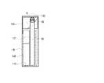
도 1은 본 고안의 제 1 실시예에 따른 기화 흡입 장치용 충전 장치를 보이는 사시도이고, 도 2는 도 1에 도시된 A부분에 대한 확대도이고, 도 3은 본 고안의 제 1 실시예에 따른 기화 흡입 장치용 충전 장치에서 충전 장치측 충전 부재가 기화 흡입 장치측 충전 부재에 연결된 모습을 보이는 단면도이고, 도 4는 도 3에 도시된 B부분에 대한 확대도이고, 도 5는 본 고안의 제 1 실시예에 따른 기화 흡입 장치용 충전 장치에서 충전 장치측 충전 부재가 기화 흡입 장치측 충전 부재에서 분리된 모습을 보이는 단면도이고, 도 6은 도 5에 도시된 C부분에 대한 확대도이다.1 is a perspective view showing a charging device for a vaporization suction device according to a first embodiment of the present invention, Figure 2 is an enlarged view of the portion A shown in Figure 1, Figure 3 is a first embodiment of the present invention In the charging device for a vaporization suction device according to the present invention is a cross-sectional view showing that the charging device side charging member is connected to the vaporization suction device side charging member, Figure 4 is an enlarged view of the portion B shown in Figure 3, Figure 5 is In the charging device for a vaporization suction apparatus according to the first embodiment, it is a cross-sectional view showing that the charging device side charging member is separated from the vaporization suction device side charging member, Figure 6 is an enlarged view of the portion C shown in FIG.
도 1 내지 도 6을 함께 참조하면, 본 실시예에 따른 기화 흡입 장치용 충전 장치(100)는 충전 장치 몸체(110)와, 충전 장치 덮개(120)와, 충전 장치측 충전 부재(130)와, 충전 장치측 충전지(140)를 포함하여, 사용자가 흡입할 수 있도록 내부에 수용된 기화 대상체를 흡입 대상 기체로 기화할 수 있는 기화 흡입 장치의 내부에 수용된 기화 흡입 장치측 충전지를 충전시킬 수 있고, 휴대할 수 있는 것이다.1 to 6 together, the
도면 번호 10은 연기 제조 장치, 필터 등이 수용된 기화 흡입 장치의 후측 부재이고, 도면 번호 50은 기화 흡입 장치측 충전지 등이 수용된 기화 흡입 장치의 전측 부재이다. 상기 전측 부재(50)와 상기 후측 부재(10)가 결합되어, 상기 기화 흡입 장치를 이룰 수 있다.
여기서, 상기 기화 흡입 장치가 상기 전측 부재(50) 및 상기 후측 부재(10)로 구성되는 것과, 상기 전측 부재(50)에 연기 제조 장치, 필터 등이 수용되고, 상기 후측 부재(10)에 상기 기화 흡입 장치측 충전지 등이 수용되는 것으로 제시되나, 이는 예시적인 것이고, 상기 기화 흡입 장치는 단일체 또는 더 많은 갯수의 부재로 구성될 수 있고, 그 각 부재 내부에도 구성 요소들이 다양한 조합으로 수용될 수 있다.Here, the vaporization suction device is composed of the
또한, 상기 기화 흡입 장치의 내부에 수용되는 기화 대상체로는 니코틴 액, 주사액, 아로마 등의 각종 향료, 기능성 성분 포함 물질, 건강 보조 성분 포함 물질, 의약 성분 포함 물질 등이 제시될 수 있고, 그러한 기화 대상체의 형태는 액체 또는 고체로 제시될 수 있다. 기화 대상체가 고체인 경우, 그러한 고체를 가열시켜 액화시킨 후 기화시킬 수 있다. 이러한 기화 대상체가 기화 흡입 장치 내에서 기화됨으로써 사용자에게 흡입될 수도 있다.In addition, the vaporization object accommodated in the vaporization inhalation device may be presented with various flavors such as nicotine liquid, injection liquid, aroma, functional ingredient-containing material, health supplement-containing material, pharmaceutical ingredient-containing material, etc. The form of the subject may be presented as a liquid or a solid. If the vaporized subject is a solid, the solid may be heated to liquefy and then vaporized. Such a vaporized object may be inhaled by a user by being vaporized in a vaporization inhalation device.
도면 번호 55는 기화 흡입 장치측 충전 부재로서, 상기 기화 흡입 장치측 충전 부재(55)는 상기 기화 흡입 장치측 충전지의 일 극에 연결된 제 1 기화 흡입 장치측 충전극(56)과, 상기 기화 흡입 장치측 충전지의 다른 극에 연결된 제 2 기화 흡입 장치측 충전극(57)을 포함한다. 예시적으로, 상기 제 2 기화 흡입 장치측 충전극(57)은 상기 제 1 기화 흡입 장치측 충전극(56) 주변을 따라 환형으로 형성될 수 있다.
상기 충전 장치 몸체(110)는 휴대가 간편하도록 예시적으로 담뱃갑 형상 등으로 이루어질 수 있고, 상부에 복수 개의 후측 부재 삽입 홀(116)이 형성된 결합부(115)가 형성된다. 상기 결합부(115)에 형성된 상기 복수 개의 후측 부재 삽입 홀(116)에는 상기 후측 부재(10)가 삽입되어, 휴대될 수 있다. 그리고, 상기 충전 장치 몸체(110)에는 상기 전측 부재(50)가 삽입될 수 있는 전측 부재 삽입 홀(117)이 형성된다.The
여기서, 상기 후측 부재 삽입 홀(116)의 형성은 선택적인 것으로, 슬림화 등 필요에 따라 형성되지 아니할 수도 있다.Here, the formation of the rear
상기 충전 장치 몸체(110)에는 디스플레이부(118)가 형성될 수 있다. 상기 디스플레이부(118)에는 상기 충전 장치측 충전지(140)의 충전 정도, 상기 기화 흡입 장치측 충전지의 충전 정도, 현재 날짜, 현재 시간 등 다양한 정보가 표시될 수 있다. 상기 디스플레이부(118)는 LCD, LED 등 다양한 수단을 이용하여 정보를 표시할 수 있다.The
또한, 상기 후측 부재 삽입 홀(116) 및 상기 전측 부재 삽입 홀(117)에 감지 센서를 각각 배치하여, 상기 후측 부재 삽입 홀(116) 및 상기 전측 부재 삽입 홀(117)에 상기 후측 부재(10) 및 상기 전측 부재(50)가 삽입되었는지 여부를 감지시킬 수 있다. 이 경우, 상기와 같이 감지된 상기 후측 부재 삽입 홀(116) 및 상기 전측 부재 삽입 홀(117) 내에 삽입된 상기 후측 부재(10) 및 상기 전측 부재(50)의 갯수가 상기 디스플레이부(118)에 표시될 수 있다.In addition, a sensing sensor is disposed in the rear
여기서, 상기 디스플레이부(118)가 상기 충전 장치 몸체(110)에 형성되는 것으로 제시되나, 상기 충전 장치 덮개(120) 등에도 배치될 수 있음은 물론이다.Here, the
한편, 상기 충전 장치 몸체(110)에 상기 디스플레이부(118) 외에 별도의 완충 표시등이 설치되어, 상기 기화 흡입 장치측 충전지의 완충 여부 등을 표시할 수도 있다.On the other hand, in addition to the
상기 충전 장치측 충전지(140)는 상기 충전 장치 몸체(110) 내부에 수용되고, 외부 전원에 연결되어 충전될 수 있는 것이다. 이러한 충전 장치측 충전지(140)의 충전이 가능하도록, 상기 충전 장치 몸체(110)에는 상기 충전 장치측 충전지(140)와 외부 전원을 연결시킬 수 있는 외부 전원 연결 단자(141)가 형성될 수 있다.The charging device side
상기 충전 장치 덮개(120)는 그 일측 말단이 상기 충전 장치 몸체(110)에 회전 가능하게 연결되어, 그러한 회전에 따라 상기 충전 장치 몸체(110)를 개폐시킬 수 있는 것이다. 즉, 도 3에 도시된 바와 같이, 상기 충전 장치 덮개(120)가 상기 충전 장치 몸체(110)를 덮도록 회동될 수도 있고, 도 5에 도시된 바와 같이, 상기 충전 장치 덮개(120)가 상기 충전 장치 몸체(110)를 열도록 회동될 수도 있다.One end of the
여기서, 상기 충전 장치 덮개(120)가 상기 충전 장치 몸체(110)에 대하여 회전되는 형태로 작동되는 것으로 제시되나, 이는 예시적인 것이고, 상기 충전 장치 덮개(120)는 상기 충전 장치 몸체(110)에 대하여 슬라이딩 등 다양한 형태로 작동 되면서, 상기 충전 장치 몸체(110)를 개폐시킬 수 있다.Here, the charging
상기 충전 장치측 충전 부재(130)는 상기 충전 장치측 충전지(140)와 전기적으로 연결되면서, 상기 충전 장치 덮개(120)에 배치되는 것으로, 상기 기화 흡입 장치측 충전 부재(55)와 연결됨으로써, 상기 기화 흡입 장치측 충전지와 상기 충전 장치측 충전지(140)를 전기적으로 연결시킬 수 있는 것이다.The charging device
여기서, 상기 충전 장치측 충전지(140)로부터 연장된 전선이 상기 충전 장치 몸체(110) 및 상기 충전 장치 덮개(120)를 따라 설치되어, 상기 충전 장치측 충전 부재(130)에 연결되는 방식 등에 의해, 상기 충전 장치측 충전지(140)와 상기 충전 장치측 충전 부재(130)가 전기적으로 연결될 수 있다.Here, the electric wire extending from the charging device side
상기 충전 장치 덮개(120)가 상기 충전 장치 몸체(110)를 덮도록 회동되면, 상기 충전 장치 몸체(110)에 수용된 상기 전측 부재(50)에 형성된 상기 기화 흡입 장치측 충전 부재(55)와 상기 충전 장치 덮개(120)에 형성된 상기 충전 장치측 충전 부재(130)가 연결되면서, 상기 기화 흡입 장치측 충전지와 상기 충전 장치측 충전지(140)가 전기적으로 연결된다.When the charging
반면, 상기 충전 장치 덮개(120)가 상기 충전 장치 몸체(110)를 열도록 회동되면, 상기 충전 장치 몸체(110)에 수용된 상기 전측 부재(50)에 형성된 상기 기화 흡입 장치측 충전 부재(55)와 상기 충전 장치 덮개(120)에 형성된 상기 충전 장치측 충전 부재(130)의 연결이 해제되면서, 상기 기화 흡입 장치측 충전지와 상기 충전 장치측 충전지(140)의 전기적 연결이 해제된다.On the other hand, when the charging
상기와 같이, 상기 충전 장치측 충전 부재(130)가 상기 충전 장치 덮개(120) 에 배치됨에 따라, 상기 기화 흡입 장치측 충전 부재(55)가 상기 충전 장치 덮개(120)를 향하도록 상기 전측 부재(50)를 상기 전측 부재 삽입 홀(117)에 삽입할 수 있다. 따라서, 작업자는 한 손으로 상기 충전 장치 몸체(110)를 잡고, 다른 한 손으로 상기 전측 부재 삽입 홀(117)에 상기 후측 부재(10)와 연결된 상태의 상기 전측 부재(50)를 삽입한 후, 그 다른 한 손으로 상기 후측 부재(10)를 상기 전측 부재(50)로부터 분리시킬 수 있으므로, 충전 장치를 바닥에 방치하여야 하는 등의 불편함이 해소되어, 간편하게 상기 기화 흡입 장치를 충전시킬 수 있다.As described above, as the charging device
한편, 상기 충전 장치측 충전 부재(130)는 상기 제 1 기화 흡입 장치측 충전극(56)에 연결될 수 있는 제 1 충전 장치측 충전극(131)과, 상기 제 2 기화 흡입 장치측 충전극(57)에 연결될 수 있는 제 2 충전 장치측 충전극을 포함한다.Meanwhile, the charging device
상기 제 2 충전 장치측 충전극은 제 1 탄성부(133)와, 제 2 탄성부(134)와, 연결부(132)로 구성된다.The second charging device side charging electrode includes a first
상기 제 1 탄성부(133)는 복수 번 굽혀지면서 연결된 부분들(133a, 133b, 133c)로 이루어지고, 상기 제 2 탄성부(134)도 복수 번 굽혀지면서 연결된 부분들(134a, 134b, 134c)로 이루어지고, 상기 연결부(132)는 환형을 이루면서 상기 제 1 탄성부(133)와 상기 제 2 탄성부(134)를 연결할 수 있다. 상기 제 1 탄성부(133)와 상기 제 2 탄성부(134)는 탄성을 가진다. 상기 제 2 기화 흡입측 충전극(57)과의 원활한 연결을 위하여, 상기 제 1 탄성부(133)와 상기 제 2 탄성부(134)의 각 말단부(133a, 134a)는 외향되도록 형성될 수 있다.The first
여기서, 상기 제 2 충전 장치측 충전극의 일부가 탄성을 가지는 것으로 제시 되나, 이는 예시적인 것이고, 상기 제 1 충전 장치측 충전극(131)이 탄성을 가질 수도 있고, 양자 모두 탄성을 가지도록 구성될 수도 있다.Here, a part of the second charging device-side charging electrode is shown as having elasticity, but this is exemplary, and the first charging device-
상기와 같이 형성되면, 상기 충전 장치 덮개(120)가 상기 충전 장치 몸체(110)를 덮도록 회동될 때, 상기 제 1 탄성부(133)와 상기 제 2 탄성부(134)가 상기 제 2 기화 흡입측 충전극(57)에 닿으면서 벌어진다. 이 때, 상기 제 1 탄성부(133)와 상기 제 2 탄성부(134)에는 탄성력이 축적된다.When formed as described above, when the charging
상기 충전 장치 덮개(120)가 상기 충전 장치 몸체(110)를 완전히 덮게 되면, 상기 제 1 탄성부(133)와 상기 제 2 탄성부(134)는 벌어진 채로 상기 제 2 기화 흡입측 충전극(57)에 닿은 상태가 되고, 그에 따라 상기 제 2 충전 장치측 충전극이 상기 제 2 기화 흡입측 충전극(57)과 통전 가능한 상태가 된다. 그리고, 상기 제 1 충전 장치측 충전극(131)이 상기 제 1 기화 흡입측 충전극(56)에 닿아, 상기 제 1 충전 장치측 충전극(131)이 상기 제 1 기화 흡입측 충전극(56)과 통전 가능한 상태가 된다. 그러면, 상기 충전 장치측 충전 부재(130)와 상기 기화 흡입 장치측 충전 부재(55)가 통전 가능한 상태가 된다.When the charging
여기서, 상기 제 1 탄성부(133)와 상기 제 2 탄성부(134)가 탄성을 제공함에 따라, 상기 기화 흡입 장치측 충전 부재(55)와 상기 충전 장치측 충전 부재(130)의 연결이 긴밀하게 유지될 수 있다.Here, as the first
한편, 상기 충전 장치 덮개(120)가 상기 충전 장치 몸체(110)를 열도록 회동될 때, 상기 제 1 충전 장치측 충전극(131)과 상기 제 2 충전 장치측 충전극은 각각 상기 제 1 기화 흡입측 충전극(56)과 상기 제 2 기화 흡입측 충전극(57)과 분리 되고, 그에 따라 상기 충전 장치측 충전 부재(130)와 상기 기화 흡입 장치측 충전 부재(55)는 통전 불가능한 분리 상태가 된다.On the other hand, when the charging
이 때, 상기 제 1 탄성부(133)와 상기 제 2 탄성부(134)의 탄성력에 의해, 상기 제 1 탄성부(133)와 상기 제 2 탄성부(134)는 원상태로 회복된다.At this time, by the elastic force of the first
상기와 같이 구성되면, 상기 전측 부재(50)를 수 회 회전시키는 등 작업자의 전극 연결을 위한 별도 조작 없이도, 상기 전측 부재(50)를 상기 충전 장치 몸체(110)에 결합한 상태에서 상기 충전 장치 덮개(120)를 덮는 것만으로도, 자동적으로 상기 충전 장치측 충전 부재(130)와 상기 기화 흡입 장치측 충전 부재(55)가 통전 가능한 상태가 될 수 있으므로, 간편하게 상기 기화 흡입 장치를 충전시킬 수 있다.When configured as described above, the charging device cover in a state in which the
이하에서는, 상기 기화 흡입 장치용 충전 장치(100)의 작동에 대하여 설명한다.Hereinafter, the operation of the charging device for
먼저, 상기 충전 장치 덮개(120)를 연 상태에서, 작업자가 한 손으로 상기 충전 장치 몸체(110)를 잡고 상기 후측 부재(10)가 연결된 상태의 상기 전측 부재(50)를 상기 충전 장치 몸체(110)에 결합시킨 후, 작업자가 다른 한 손으로 상기 후측 부재(10)를 상기 전측 부재(50)로부터 분리시킨다. 물론, 여기서 상기 후측 부재(10)가 분리된 상태의 상기 전측 부재(50)를 상기 충전 장치 몸체(110)에 결합시킬 수도 있다.First, in the state in which the
그런 다음, 상기 충전 장치 덮개(120)를 덮으면, 상기 충전 장치측 충전 부재(130)와 상기 기화 흡입 장치측 충전 부재(55)가 자동적으로 통전 가능하게 되 고, 그에 따라 상기 충전 장치측 충전지(140)의 전기 에너지가 상기 기화 흡입 장치측 충전지로 전달되어, 상기 기화 흡입 장치측 충전지가 충전될 수 있다.Then, when the charging
상기 충전이 완료되는 등의 이유로, 상기 충전 장치 덮개(120)를 열면, 상기 충전 장치측 충전 부재(130)와 상기 기화 흡입 장치측 충전 부재(55)의 연결이 자동적으로 해제되고, 그에 따라 상기 기화 흡입 장치측 충전지의 충전이 자동적으로 중지될 수 있다.When the charging
이하에서는 도면을 참조하여 본 고안의 제 2 실시예에 따른 기화 흡입 장치용 충전 장치에 대하여 설명한다. 이러한 설명을 수행함에 있어서, 상기된 본 고안의 제 1 실시예에서 이미 기재된 내용과 중복되는 설명은 그에 갈음하고, 여기서는 생략하기로 한다.Hereinafter, a charging device for a vaporization suction device according to a second embodiment of the present invention will be described with reference to the drawings. In carrying out this description, descriptions overlapping with those already described in the above-described first embodiment of the present invention will be replaced with the description thereof, and will be omitted herein.
도 7은 본 고안의 제 2 실시예에 따른 기화 흡입 장치용 충전 장치의 일부를 보이는 사시도이다.7 is a perspective view showing a part of a charging device for a vaporization suction device according to a second embodiment of the present invention.
도 7을 참조하면, 본 실시예에서는, 충전 장치 덮개(220)가 충전측 덮개(222)와, 비충전측 덮개(221)로 구성된다.Referring to FIG. 7, in the present embodiment, the charging
기화 흡입 장치를 구성하는 전측 부재(50)는 기화 흡입 장치측 충전지 및 기화 흡입 장치측 충전 부재(55)가 형성된 것으로, 이러한 측면에서 상기 전측 부재(50)는 충전측 부재로 정의될 수 있다. 그리고, 상기 기화 흡입 장치를 구성하는 후측 부재(10)는 상기 기화 흡입 장치측 충전지 및 상기 기화 흡입 장치측 충전 부재(55)가 형성되지 아니한 것으로, 이러한 측면에서 상기 후측 부재(10)는 비충전측 부재로 정의될 수 있다.The
상기 충전측 덮개(222)는 충전 장치 몸체(210)에 결합된 상기 충전측 부재로 정의되는 상기 전측 부재(50)를 덮을 수 있고, 상기 비충전측 덮개(221)는 상기 충전 장치 몸체(210)에 결합된 상기 비충전측 부재로 정의되는 상기 후측 부재(10)를 덮을 수 있다.The charging
상기 충전측 덮개(222)에는 상기 기화 흡입 장치측 충전 부재(55)와 통전 가능하도록 연결될 수 있는 충전 장치측 충전 부재(230)가 형성된다.The charging
상기 충전측 덮개(222)와 상기 비충전측 덮개(221)는 독립적으로 회동되면서, 독립적으로 각각 상기 전측 부재(50)와 상기 후측 부재(10)를 덮을 수 있다.The charging
상기와 같이 구성되면, 상기 충전측 덮개(222)와 상기 비충전측 덮개(221)가 독립적으로 회동되면서, 독립적으로 각각 상기 충전측 부재로 정의되는 상기 전측 부재(50)와 상기 비충전측 부재로 정의되는 상기 후측 부재(10)를 덮을 수 있으므로, 상기 전측 부재(50)에 대한 충전을 지속하면서 상기 후측 부재(10)를 꺼낼 수 있고, 상기 후측 부재(10)를 덮은 상태에서 상기 전측 부재(50)를 꺼낼 수 있는 등 그 편리함이 증대될 수 있다.When configured as described above, the charging
도 8은 본 고안의 제 3 실시예에 따른 기화 흡입 장치용 충전 장치의 일부를 보이는 사시도이다.8 is a perspective view showing a part of a charging device for a vaporization suction device according to a third embodiment of the present invention.
도 8을 참조하면, 본 실시예에 따른 기화 흡입 장치용 충전 장치(300)는 조명 부재(360)를 더 포함한다.Referring to FIG. 8, the charging
상기 조명 부재(360)는 충전 장치측 충전지에 전기적으로 연결된 상태로, 충전 장치 덮개(320) 등에 형성되어, 상기 충전 장치 몸체(310) 쪽으로 광을 조사할 수 있다.The
충전 장치 몸체(310)에서 상기 충전 장치 덮개(320)가 닿는 부분, 예를 들어 상기 충전 장치 몸체(310)의 결합부(315)에 상기 충전 장치 덮개(320)가 상기 충전 장치 몸체(310)를 덮는지 여부를 감지하는 센서(350)가 배치될 수 있다. 상기 센서(350)는 상기 충전 장치 덮개(320)가 상기 충전 장치 몸체(310)를 덮는지 여부를 감지하는 것으로, 압력 감지 센서 등이 적용될 수 있다.In the
상기 센서(350)에서 상기 충전 장치 덮개(320)가 상기 충전 장치 몸체(310)를 덮는 것으로 감지되면, 상기 조명 부재(360)는 꺼지고, 상기 센서(350)에서 상기 충전 장치 덮개(320)가 상기 충전 장치 몸체(310)를 여는 것으로 감지되면, 상기 조명 부재(360)는 켜질 수 있다. 그러면, 상기 조명 부재(360)의 작동 효율이 향상되면서도, 어두운 곳에서 작업자가 상기 충전 장치(300) 내부를 손쉽게 인지 및 접근할 수 있다.If the
도 9는 본 고안의 제 4 실시예에 따른 기화 흡입 장치용 충전 장치의 일부를 보이는 사시도이다.9 is a perspective view showing a part of a charging device for a vaporization suction device according to a fourth embodiment of the present invention.
도 9를 참조하면, 본 실시예에 따른 기화 흡입 장치용 충전 장치(400)는 자외선 발생 부재(470)를 포함한다.Referring to FIG. 9, the charging
상기 자외선 발생 부재(470)는 충전 장치 덮개(420) 등에 설치되어, 충전 장치 몸체(410)에 삽입된 전측 부재(50)와 후측 부재(10) 중 적어도 하나에 자외선을 조사하여, 살균시킬 수 있다.The
상기 충전 장치 몸체(410)의 결합부(415)에 상기 충전 장치 덮개(420)가 상 기 충전 장치 몸체(410)를 덮는지 여부를 감지하는 센서(450)가 배치될 수 있다.A
이 경우, 상기 센서(450)에서 상기 충전 장치 덮개(420)가 상기 충전 장치 몸체(410)를 덮는 것으로 감지되면, 상기 자외선 발생 부재(470)는 켜지고, 상기 충전 장치 덮개(420)가 상기 충전 장치 몸체(410)를 여는 것으로 감지되면, 상기 자외선 발생 부재(470)는 꺼질 수 있다. 그러면, 상기 자외선 발생 부재(470)의 작동 효율이 향상되면서도, 상기 충전 장치(400)에 삽입된 상기 전측 부재(50)와 상기 후측 부재(10)가 살균될 수 있다.In this case, when the
상기 충전 장치 덮개(420)에 조명 부재(460)가 더 설치될 수 있는데, 이 경우, 상기 센서(450)에서 상기 충전 장치 덮개(420)가 상기 충전 장치 몸체(410)를 덮는 것으로 감지되면, 상기 조명 부재(460)는 꺼지고, 상기 자외선 발생 부재(470)는 켜지며, 상기 충전 장치 덮개(420)가 상기 충전 장치 몸체(410)를 여는 것으로 감지되면, 상기 조명 부재(460)는 켜지고, 상기 자외선 발생 부재(470)는 꺼질 수 있다.An
도 10은 본 고안의 제 5 실시예에 따른 기화 흡입 장치용 충전 장치를 보이는 단면도이다.10 is a cross-sectional view showing a charging device for a vaporization suction device according to a fifth embodiment of the present invention.
도 10을 참조하면, 본 실시예에 따른 기화 흡입 장치용 충전 장치(500)는 정보 저장 부재(580)를 더 포함한다.Referring to FIG. 10, the charging
상기 정보 저장 부재(580)는 충전 장치 몸체(510)에 설치될 수 있다. 이러한 정보 저장 부재(580)에는 각종 정보가 저장될 수 있다.The
상기 정보 저장 부재(580)와 외부의 컴퓨터 등의 전자 장치를 연결하기 위한 연결선이 삽입되는 연결선 삽입 홀(581)이 상기 충전 장치 몸체(510)에 형성됨으로써, 상기 정보 저장 부재(580)가 외부의 전자 장치와 정보를 교환하면서 정보를 저장할 수 있다.A connection
물론, 상기 정보 저장 부재(580)에서 USB 방식 등의 결합부가 돌출되어, 상기 결합부를 통해 상기 정보 저장 부재(580)가 연결선 없이도 외부의 전자 장치와 연결될 수 있음은 물론이다.Of course, a coupling part such as a USB method protrudes from the
상기에서 본 고안은 특정한 실시예에 관하여 도시되고 설명되었지만, 당업계에서 통상의 지식을 가진 자라면 이하의 특허청구범위에 기재된 본 고안의 사상 및 영역을 벗어나지 않는 범위 내에서 본 고안을 다양하게 수정 및 변경시킬 수 있음을 알 수 있을 것이다. 그렇지만 이러한 수정 및 변형 구조들은 모두 본 고안의 권리범위 내에 포함되는 것임을 분명하게 밝혀두고자 한다.While the present invention has been shown and described with respect to specific embodiments, those skilled in the art can variously modify the present invention without departing from the spirit and scope of the present invention as set forth in the claims below. And that it can be changed. Nevertheless, it is intended to be clear that all such modifications and variations are included within the scope of the present invention.
본 고안의 일 측면에 따른 기화 흡입 장치용 충전 장치에 의하면, 간편하게 기화 흡입 장치를 충전시킬 수 있으므로, 그 산업상 이용 가능성이 높다고 하겠다.According to the charging device for a vaporization suction device according to an aspect of the present invention, since the vaporization suction device can be easily charged, it is said that the industrial applicability is high.
도 1은 본 고안의 제 1 실시예에 따른 기화 흡입 장치용 충전 장치를 보이는 사시도.1 is a perspective view showing a charging device for a vaporization suction device according to a first embodiment of the present invention.
도 2는 도 1에 도시된 A부분에 대한 확대도.FIG. 2 is an enlarged view of a portion A shown in FIG. 1. FIG.
도 3은 본 고안의 제 1 실시예에 따른 기화 흡입 장치용 충전 장치에서 충전 장치측 충전 부재가 기화 흡입 장치측 충전 부재에 연결된 모습을 보이는 단면도.3 is a cross-sectional view showing a charging device side charging member connected to the vaporization suction device side charging member in the charging device for a vaporization suction device according to a first embodiment of the present invention.
도 4는 도 3에 도시된 B부분에 대한 확대도.4 is an enlarged view of a portion B shown in FIG. 3.
도 5는 본 고안의 제 1 실시예에 따른 기화 흡입 장치용 충전 장치에서 충전 장치측 충전 부재가 기화 흡입 장치측 충전 부재에서 분리된 모습을 보이는 단면도.5 is a cross-sectional view showing a state in which the charging device side charging member is separated from the vaporization suction device side charging member in the charging device for a vaporization suction device according to a first embodiment of the present invention.
도 6은 도 5에 도시된 C부분에 대한 확대도.FIG. 6 is an enlarged view of a portion C shown in FIG. 5. FIG.
도 7은 본 고안의 제 2 실시예에 따른 기화 흡입 장치용 충전 장치의 일부를 보이는 사시도.7 is a perspective view showing a part of a charging device for a vaporization suction device according to a second embodiment of the present invention.
도 8은 본 고안의 제 3 실시예에 따른 기화 흡입 장치용 충전 장치의 일부를 보이는 사시도.8 is a perspective view showing a part of a charging device for a vaporization suction device according to a third embodiment of the present invention.
도 9는 본 고안의 제 4 실시예에 따른 기화 흡입 장치용 충전 장치의 일부를 보이는 사시도.9 is a perspective view showing a part of a charging device for a vaporization suction device according to a fourth embodiment of the present invention.
도 10은 본 고안의 제 5 실시예에 따른 기화 흡입 장치용 충전 장치를 보이는 단면도.10 is a cross-sectional view showing a charging device for a vaporization suction device according to a fifth embodiment of the present invention.
Claims (10)
Translated fromKoreanPriority Applications (1)
| Application Number | Priority Date | Filing Date | Title |
|---|---|---|---|
| KR2020090012857UKR200460461Y1 (en) | 2009-09-30 | 2009-09-30 | Charging apparatus for vaporizing and inhaling apparatus |
Applications Claiming Priority (1)
| Application Number | Priority Date | Filing Date | Title |
|---|---|---|---|
| KR2020090012857UKR200460461Y1 (en) | 2009-09-30 | 2009-09-30 | Charging apparatus for vaporizing and inhaling apparatus |
Publications (2)
| Publication Number | Publication Date |
|---|---|
| KR20110003475U KR20110003475U (en) | 2011-04-06 |
| KR200460461Y1true KR200460461Y1 (en) | 2012-05-25 |
Family
ID=44208816
Family Applications (1)
| Application Number | Title | Priority Date | Filing Date |
|---|---|---|---|
| KR2020090012857UExpired - Fee RelatedKR200460461Y1 (en) | 2009-09-30 | 2009-09-30 | Charging apparatus for vaporizing and inhaling apparatus |
Country Status (1)
| Country | Link |
|---|---|
| KR (1) | KR200460461Y1 (en) |
Cited By (17)
| Publication number | Priority date | Publication date | Assignee | Title |
|---|---|---|---|---|
| US10218193B2 (en) | 2014-07-29 | 2019-02-26 | Nicoventures Holdings Limited | E-cigarette and re-charging pack |
| KR20190049630A (en)* | 2017-10-30 | 2019-05-09 | 주식회사 케이티앤지 | Aerosol generating device and method for controlling the same |
| US11178910B2 (en) | 2017-05-11 | 2021-11-23 | Kt&G Corporation | Vaporizer and aerosol generation device including same |
| US11344067B2 (en) | 2017-10-30 | 2022-05-31 | Kt&G Corporation | Aerosol generating apparatus having air circulation hole and groove |
| US11350673B2 (en) | 2017-10-30 | 2022-06-07 | Kt&G Corporation | Aerosol generating device and method for controlling same |
| US11369145B2 (en) | 2017-10-30 | 2022-06-28 | Kt&G Corporation | Aerosol generating device including detachable vaporizer |
| US11478015B2 (en) | 2017-10-30 | 2022-10-25 | Kt&G Corporation | Vaporizer of an aerosol generating device having a leakage-preventing structure |
| US11528936B2 (en) | 2017-10-30 | 2022-12-20 | Kt&G Corporation | Aerosol generating device |
| US11622579B2 (en) | 2017-10-30 | 2023-04-11 | Kt&G Corporation | Aerosol generating device having heater |
| US11622580B2 (en) | 2017-10-30 | 2023-04-11 | Kt&G Corporation | Aerosol generation device and generation method |
| US11700884B2 (en) | 2017-10-30 | 2023-07-18 | Kt&G Corporation | Aerosol generation device and heater for aerosol generation device |
| US11700886B2 (en) | 2017-10-30 | 2023-07-18 | Kt&G Corporation | Aerosol generating device and heater assembly for aerosol generating device |
| US11700885B2 (en) | 2017-10-30 | 2023-07-18 | Kt&G Corporation | Aerosol generation device including mainstream smoke passage and pressure detection passage |
| US11974611B2 (en) | 2017-10-30 | 2024-05-07 | Kt&G Corporation | Method for controlling temperature of heater included in aerosol generation device according to type of cigarette, and aerosol generation device for controlling temperature of heater according to type of cigarette |
| US12048328B2 (en) | 2017-10-30 | 2024-07-30 | Kt&G Corporation | Optical module and aerosol generation device comprising same |
| RU2834335C2 (en)* | 2012-01-03 | 2025-02-05 | Филип Моррис Продактс С.А. | Power supply system for portable aerosol generating device |
| US12317923B2 (en) | 2017-10-30 | 2025-06-03 | Kt&G Corporation | Aerosol generating device |
Families Citing this family (9)
| Publication number | Priority date | Publication date | Assignee | Title |
|---|---|---|---|---|
| WO2013189052A1 (en)* | 2012-06-20 | 2013-12-27 | Liu Qiuming | Electronic cigarette case |
| GB201413027D0 (en)* | 2014-02-28 | 2014-09-03 | Beyond Twenty Ltd | Beyond 4 |
| WO2016012795A1 (en) | 2014-07-24 | 2016-01-28 | Nicoventures Holdings Limited | Re-charging pack for an e-cigarette |
| GB2524735B (en) | 2014-03-31 | 2017-10-25 | Nicoventures Holdings Ltd | Re-charging pack for an e-cigarette |
| GB2524736B (en) | 2014-03-31 | 2021-02-24 | Nicoventures Holdings Ltd | Re-charging pack for an e-cigarette |
| JP7244169B2 (en)* | 2017-05-26 | 2023-03-22 | ケーティー アンド ジー コーポレイション | Charging system for aerosol generator |
| CN109512032B (en)* | 2018-12-10 | 2024-08-02 | 深圳麦克韦尔科技有限公司 | Smoking set |
| CN110574973B (en)* | 2019-10-23 | 2022-03-11 | 深圳市施美乐科技股份有限公司 | Sterilizing box for electronic cigarette |
| CN115779807A (en)* | 2022-10-10 | 2023-03-14 | 深圳麦克韦尔科技有限公司 | Aerosol generating device, charging box and parameter display method |
Citations (2)
| Publication number | Priority date | Publication date | Assignee | Title |
|---|---|---|---|---|
| KR900004280A (en)* | 1988-09-08 | 1990-04-12 | 지.로버트 디 마르코 | Smoking goods using electric energy |
| KR20070087265A (en)* | 2003-04-29 | 2007-08-28 | 베스트 파트너스 월드와이드 리미티드 | Nonflammable Electronic Spray Cigarette |
- 2009
- 2009-09-30KRKR2020090012857Upatent/KR200460461Y1/ennot_activeExpired - Fee Related
Patent Citations (2)
| Publication number | Priority date | Publication date | Assignee | Title |
|---|---|---|---|---|
| KR900004280A (en)* | 1988-09-08 | 1990-04-12 | 지.로버트 디 마르코 | Smoking goods using electric energy |
| KR20070087265A (en)* | 2003-04-29 | 2007-08-28 | 베스트 파트너스 월드와이드 리미티드 | Nonflammable Electronic Spray Cigarette |
Cited By (28)
| Publication number | Priority date | Publication date | Assignee | Title |
|---|---|---|---|---|
| RU2834335C2 (en)* | 2012-01-03 | 2025-02-05 | Филип Моррис Продактс С.А. | Power supply system for portable aerosol generating device |
| US10218193B2 (en) | 2014-07-29 | 2019-02-26 | Nicoventures Holdings Limited | E-cigarette and re-charging pack |
| US12095052B2 (en) | 2014-07-29 | 2024-09-17 | Nicoventures Trading Limited | E-cigarette and re-charging pack |
| US10536013B2 (en) | 2014-07-29 | 2020-01-14 | Nicoventures Holdings Limited | E-cigarette and re-charging pack |
| US10873196B2 (en) | 2014-07-29 | 2020-12-22 | Nicoventures Holdings Limited | E-cigarette and re-charging pack |
| US11811027B2 (en) | 2014-07-29 | 2023-11-07 | Nicoventures Trading Limited | E-cigarette and re-charging pack |
| US11178910B2 (en) | 2017-05-11 | 2021-11-23 | Kt&G Corporation | Vaporizer and aerosol generation device including same |
| US11700884B2 (en) | 2017-10-30 | 2023-07-18 | Kt&G Corporation | Aerosol generation device and heater for aerosol generation device |
| US11800603B2 (en) | 2017-10-30 | 2023-10-24 | Kt&G Corporation | Aerosol generating device having heater |
| US11478015B2 (en) | 2017-10-30 | 2022-10-25 | Kt&G Corporation | Vaporizer of an aerosol generating device having a leakage-preventing structure |
| US11528936B2 (en) | 2017-10-30 | 2022-12-20 | Kt&G Corporation | Aerosol generating device |
| US11622579B2 (en) | 2017-10-30 | 2023-04-11 | Kt&G Corporation | Aerosol generating device having heater |
| US11622580B2 (en) | 2017-10-30 | 2023-04-11 | Kt&G Corporation | Aerosol generation device and generation method |
| US11696600B2 (en) | 2017-10-30 | 2023-07-11 | Kt&G Corporation | Aerosol generating device having heater |
| US11350673B2 (en) | 2017-10-30 | 2022-06-07 | Kt&G Corporation | Aerosol generating device and method for controlling same |
| US11700886B2 (en) | 2017-10-30 | 2023-07-18 | Kt&G Corporation | Aerosol generating device and heater assembly for aerosol generating device |
| US11700885B2 (en) | 2017-10-30 | 2023-07-18 | Kt&G Corporation | Aerosol generation device including mainstream smoke passage and pressure detection passage |
| US11744287B2 (en) | 2017-10-30 | 2023-09-05 | Kt&G Corporation | Aerosol generating device and method for controlling same |
| US11369145B2 (en) | 2017-10-30 | 2022-06-28 | Kt&G Corporation | Aerosol generating device including detachable vaporizer |
| US11344067B2 (en) | 2017-10-30 | 2022-05-31 | Kt&G Corporation | Aerosol generating apparatus having air circulation hole and groove |
| US11974611B2 (en) | 2017-10-30 | 2024-05-07 | Kt&G Corporation | Method for controlling temperature of heater included in aerosol generation device according to type of cigarette, and aerosol generation device for controlling temperature of heater according to type of cigarette |
| US12016390B2 (en) | 2017-10-30 | 2024-06-25 | Kt&G Corporation | Aerosol generating device and heater assembly for aerosol generating device |
| US12048328B2 (en) | 2017-10-30 | 2024-07-30 | Kt&G Corporation | Optical module and aerosol generation device comprising same |
| KR102012851B1 (en)* | 2017-10-30 | 2019-08-21 | 주식회사 케이티앤지 | Aerosol generating device and method for controlling the same |
| US12108802B2 (en) | 2017-10-30 | 2024-10-08 | Kt&G Corporation | Aerosol generating device and method for controlling same |
| KR20190049630A (en)* | 2017-10-30 | 2019-05-09 | 주식회사 케이티앤지 | Aerosol generating device and method for controlling the same |
| US12245341B2 (en) | 2017-10-30 | 2025-03-04 | Kt&G Corporation | Aerosol generating device having heater |
| US12317923B2 (en) | 2017-10-30 | 2025-06-03 | Kt&G Corporation | Aerosol generating device |
Also Published As
| Publication number | Publication date |
|---|---|
| KR20110003475U (en) | 2011-04-06 |
Similar Documents
| Publication | Publication Date | Title |
|---|---|---|
| KR200460461Y1 (en) | Charging apparatus for vaporizing and inhaling apparatus | |
| US9877520B2 (en) | Hinged vaping system | |
| CN112040797B (en) | Rechargeable electronic cigarette | |
| CN110662438B (en) | Charging system for an aerosol-generating device | |
| US12070075B2 (en) | Power supply assembly, non-combustion-type flavor inhaler, and non-combustion-type flavor inhalation system | |
| ES2774699T3 (en) | Aerosol delivery device including housing and coupler | |
| EP3051967B1 (en) | Accessory for an aerosol delivery device and related method | |
| EP2878214B1 (en) | Portable charging device for electronic cigarette | |
| KR101232619B1 (en) | Electronic cigarette with charger kit | |
| JP2020500664A (en) | Vaporizer | |
| KR20120107219A (en) | Electronic cigarette | |
| JP7465262B2 (en) | Aerosol Generation System | |
| KR20100006995U (en) | Liquid vaporizing and inhaling apparatus | |
| KR20120034933A (en) | Electronic cigarette | |
| EP4332729A1 (en) | Display device, suction device, display method, and program | |
| CN117320572A (en) | Electronic cigarette | |
| US20200352243A1 (en) | Portable vaporizer | |
| US20200029622A1 (en) | Portable vaporizer | |
| US12268238B2 (en) | Smoking substitute device | |
| EP3787425A1 (en) | Smoking substitute device having a flexible seal between battery and consumable | |
| KR20100007300U (en) | Liquid vaporizing and inhaling apparatus | |
| WO2019211340A1 (en) | Smoking substitute device having a flexible seal between battery and consumable | |
| KR20200126831A (en) | Converter for charging aerosol generating device, and system for charging the aerosol generating device | |
| KR20110084386A (en) | Liquid vaporization suction device | |
| HK1227258A1 (en) | Accessory for an aerosol delivery device and related method |
Legal Events
| Date | Code | Title | Description |
|---|---|---|---|
| A201 | Request for examination | ||
| UA0108 | Application for utility model registration | St.27 status event code:A-0-1-A10-A12-nap-UA0108 | |
| UA0201 | Request for examination | St.27 status event code:A-1-2-D10-D11-exm-UA0201 | |
| N231 | Notification of change of applicant | ||
| UN2301 | Change of applicant | St.27 status event code:A-3-3-R10-R13-asn-UN2301 St.27 status event code:A-3-3-R10-R11-asn-UN2301 | |
| R18-X000 | Changes to party contact information recorded | St.27 status event code:A-3-3-R10-R18-oth-X000 | |
| R18-X000 | Changes to party contact information recorded | St.27 status event code:A-3-3-R10-R18-oth-X000 | |
| UG1501 | Laying open of application | St.27 status event code:A-1-1-Q10-Q12-nap-UG1501 | |
| UE0902 | Notice of grounds for rejection | St.27 status event code:A-1-2-D10-D21-exm-UE0902 | |
| P11-X000 | Amendment of application requested | St.27 status event code:A-2-2-P10-P11-nap-X000 | |
| P13-X000 | Application amended | St.27 status event code:A-2-2-P10-P13-nap-X000 | |
| R18-X000 | Changes to party contact information recorded | St.27 status event code:A-3-3-R10-R18-oth-X000 | |
| E701 | Decision to grant or registration of patent right | ||
| UE0701 | Decision of registration | St.27 status event code:A-1-2-D10-D22-exm-UE0701 | |
| REGI | Registration of establishment | ||
| UR0701 | Registration of establishment | St.27 status event code:A-2-4-F10-F11-exm-UR0701 | |
| UR1002 | Payment of registration fee | St.27 status event code:A-2-2-U10-U11-oth-UR1002 Fee payment year number:1 | |
| UG1601 | Publication of registration | St.27 status event code:A-4-4-Q10-Q13-nap-UG1601 | |
| UN2301 | Change of applicant | St.27 status event code:A-5-5-R10-R13-asn-UN2301 St.27 status event code:A-5-5-R10-R11-asn-UN2301 | |
| R18-X000 | Changes to party contact information recorded | St.27 status event code:A-5-5-R10-R18-oth-X000 | |
| FPAY | Annual fee payment | Payment date:20150421 Year of fee payment:4 | |
| UR1001 | Payment of annual fee | St.27 status event code:A-4-4-U10-U11-oth-UR1001 Fee payment year number:4 | |
| R18-X000 | Changes to party contact information recorded | St.27 status event code:A-5-5-R10-R18-oth-X000 | |
| UC1903 | Unpaid annual fee | St.27 status event code:A-4-4-U10-U13-oth-UC1903 Not in force date:20160515 Payment event data comment text:Termination Category : DEFAULT_OF_REGISTRATION_FEE | |
| P22-X000 | Classification modified | St.27 status event code:A-4-4-P10-P22-nap-X000 | |
| FPAY | Annual fee payment | Payment date:20170214 Year of fee payment:5 | |
| K11-X000 | Ip right revival requested | St.27 status event code:A-6-4-K10-K11-oth-X000 | |
| R401 | Registration of restoration | ||
| UC1903 | Unpaid annual fee | St.27 status event code:N-4-6-H10-H13-oth-UC1903 Ip right cessation event data comment text:Termination Category : DEFAULT_OF_REGISTRATION_FEE Not in force date:20160515 | |
| UR0401 | Registration of restoration | St.27 status event code:A-6-4-K10-K13-oth-UR0401 | |
| UR1001 | Payment of annual fee | St.27 status event code:A-4-4-U10-U11-oth-UR1001 Fee payment year number:5 | |
| FPAY | Annual fee payment | Payment date:20170511 Year of fee payment:6 | |
| UR1001 | Payment of annual fee | St.27 status event code:A-4-4-U10-U11-oth-UR1001 Fee payment year number:6 | |
| FPAY | Annual fee payment | Payment date:20180912 Year of fee payment:7 | |
| UR1001 | Payment of annual fee | St.27 status event code:A-4-4-U10-U11-oth-UR1001 Fee payment year number:7 | |
| P22-X000 | Classification modified | St.27 status event code:A-4-4-P10-P22-nap-X000 | |
| LAPS | Lapse due to unpaid annual fee | ||
| UC1903 | Unpaid annual fee | St.27 status event code:A-4-4-U10-U13-oth-UC1903 Not in force date:20190515 Payment event data comment text:Termination Category : DEFAULT_OF_REGISTRATION_FEE | |
| UC1903 | Unpaid annual fee | St.27 status event code:N-4-6-H10-H13-oth-UC1903 Ip right cessation event data comment text:Termination Category : DEFAULT_OF_REGISTRATION_FEE Not in force date:20190515 | |
| P22-X000 | Classification modified | St.27 status event code:A-4-4-P10-P22-nap-X000 |