KR200457592Y1 - Abdominal Machine - Google Patents
Abdominal MachineDownload PDFInfo
- Publication number
- KR200457592Y1 KR200457592Y1KR2020090002934UKR20090002934UKR200457592Y1KR 200457592 Y1KR200457592 Y1KR 200457592Y1KR 2020090002934 UKR2020090002934 UKR 2020090002934UKR 20090002934 UKR20090002934 UKR 20090002934UKR 200457592 Y1KR200457592 Y1KR 200457592Y1
- Authority
- KR
- South Korea
- Prior art keywords
- fixed
- cylinder
- bracket
- pair
- outdoor
- Prior art date
- Legal status (The legal status is an assumption and is not a legal conclusion. Google has not performed a legal analysis and makes no representation as to the accuracy of the status listed.)
- Expired - Lifetime
Links
Images


Classifications
- A—HUMAN NECESSITIES
- A63—SPORTS; GAMES; AMUSEMENTS
- A63B—APPARATUS FOR PHYSICAL TRAINING, GYMNASTICS, SWIMMING, CLIMBING, OR FENCING; BALL GAMES; TRAINING EQUIPMENT
- A63B21/00—Exercising apparatus for developing or strengthening the muscles or joints of the body by working against a counterforce, with or without measuring devices
- A63B21/008—Exercising apparatus for developing or strengthening the muscles or joints of the body by working against a counterforce, with or without measuring devices using hydraulic or pneumatic force-resisters
- A63B21/0083—Exercising apparatus for developing or strengthening the muscles or joints of the body by working against a counterforce, with or without measuring devices using hydraulic or pneumatic force-resisters of the piston-cylinder type
- A—HUMAN NECESSITIES
- A63—SPORTS; GAMES; AMUSEMENTS
- A63B—APPARATUS FOR PHYSICAL TRAINING, GYMNASTICS, SWIMMING, CLIMBING, OR FENCING; BALL GAMES; TRAINING EQUIPMENT
- A63B21/00—Exercising apparatus for developing or strengthening the muscles or joints of the body by working against a counterforce, with or without measuring devices
- A63B21/40—Interfaces with the user related to strength training; Details thereof
- A63B21/4027—Specific exercise interfaces
- A63B21/4033—Handles, pedals, bars or platforms
- A63B21/4035—Handles, pedals, bars or platforms for operation by hand
- A—HUMAN NECESSITIES
- A63—SPORTS; GAMES; AMUSEMENTS
- A63B—APPARATUS FOR PHYSICAL TRAINING, GYMNASTICS, SWIMMING, CLIMBING, OR FENCING; BALL GAMES; TRAINING EQUIPMENT
- A63B21/00—Exercising apparatus for developing or strengthening the muscles or joints of the body by working against a counterforce, with or without measuring devices
- A63B21/40—Interfaces with the user related to strength training; Details thereof
- A63B21/4041—Interfaces with the user related to strength training; Details thereof characterised by the movements of the interface
- A63B21/4047—Pivoting movement
Landscapes
- Health & Medical Sciences (AREA)
- Life Sciences & Earth Sciences (AREA)
- Biophysics (AREA)
- Orthopedic Medicine & Surgery (AREA)
- General Health & Medical Sciences (AREA)
- Physical Education & Sports Medicine (AREA)
- Rehabilitation Tools (AREA)
Abstract
Translated fromKoreanDescription
Translated fromKorean본 고안은 실외 운동기구에 관한 것으로서, 더욱 상세하게는 복부 근육 운동을 하기에 적당한 실외용 업도미널 기구에 관한 것이다.The present invention relates to an outdoor exercise device, and more particularly, to an outdoor updominal device suitable for abdominal muscle exercise.
최근들어 비만 예방 또는 성인병 예방차원과, 방송 매체를 통한 몸짱 열풍으로 인해 남녀노소 대부분의 사람들이 다양한 운동을 즐겨하고 있다. 이러한 운동의 종류는 매우 다양하겠지만 최근 많은 사람들이 헬스클럽에 등록하여 운동하고 있다.Recently, due to the prevention of obesity or prevention of adult diseases, and the craze of the body through the broadcasting media, most people of all ages and young people enjoy various sports. There are many kinds of these exercises, but a lot of people have recently registered for the gym.
많은 사람들이 헬스 클럽에서 운동하는 이유는 운동기구가 다양하며, 자신의 신체 조건과 운동량에 따라 근육 운동의 중량부하를 적절하게 조절할 수 있기 때문이다. 또한, 헬스 클럽은 계절과 날씨 그리고 시간에 관계없이 운동할 수 있는 장점이 있다.Many people exercise at the gym because they have a variety of exercise equipment and can adjust the weight load of muscle exercise according to their physical condition and the amount of exercise. In addition, the gym has the advantage that you can exercise regardless of the season, weather and time.
일반적으로 헬스 클럽에서 하는 운동은 크게 유산소운동과 기구운동으로 구분할 수 있으며, 다시 운동 목적에 따라 상체 근육운동, 하체 근육운동, 복부 근육운동 등으로 구분할 수 있다.In general, the exercise in the gym can be largely divided into aerobic exercise and exercise equipment, again can be divided into upper body muscles, lower body muscles, abdominal muscles, and the like, depending on the purpose of exercise.
그 중에서 복부 근육운동을 위한 대표적인 운동기구로서, 업도미널 머신 (abdominal machine), 싣업 보드(situpboard), AB 슬라이더(slider) 등을 들 수 있다. 이러한 업도미널 머신 또는 싣업 보드를 이용한 운동은 중량추를 이용하여 사용자가 원하는 중량을 부가하여 운동하거나, 사용자가 운동할 때 누운 각도를 조절함으로써 운동의 강도를 조절하는 것이다.Among them, as an exemplary exercise device for abdominal muscle exercise, there may be mentioned an updominal machine, a situpboard, an AB slider, and the like. The exercise using the upboard machine or the mounting board is to adjust the intensity of the exercise by adding weight desired by the user using the weight, or by adjusting the lying angle when the user exercises.
그러나, 이상에서 설명한 종래의 실내 운동기구들은 실내 헬스 클럽에서 신체 건강한 남녀 성인들이 운동하기에 적당하도록 만들어졌다. 따라서, 운동기구의 전체 구성이 다소 복잡하여 설치 공간을 많이 차지하며, 사용자가 직접 중량추를 바꾸어가면서 운동하기 때문에 어린이나 노인 어르신들은 그 사용에 다소 어려움이 있었다.However, the conventional indoor exercise equipment described above is made to be suitable for exercise of healthy men and women in the indoor health club. Therefore, the overall configuration of the exercise equipment is somewhat complicated to occupy a lot of installation space, and because the user exercise while changing the weight directly, the elderly and elderly people had a somewhat difficult use.
그러나, 최근 들어 급격하게 일고 있는 웰빙(well-being) 붐과 함께 사회전반적으로 고령화가 진행됨에 따라 어린이,노인 어르신들, 일반 성인들의 레저 활동 뿐만 아니라 각종 실내,외 운동에 대한 전반적인 욕구가 증대되고 있으며, 헬스 클럽에 다니기 힘든 저소득층 주민들도 운동에 대한 욕구가 증대되고 있는 실정이다However, with the well-being boom, which is rapidly rising in recent years, the aging of the society as a whole has led to an increase in the general desire for various indoor and outdoor sports as well as leisure activities for children, seniors, and adults. In addition, low-income residents who are hard to attend health clubs are also increasing their desire for exercise.
이러한 사회 전반적인 욕구에 부응하여, 대도시뿐만 아니라 중소도시에도 야외공원에 주민 복지차원에서 다양한 운동시설들의 설치가 급증하고 있다.In response to the general needs of society, various sports facilities are installed in outdoor parks not only in large cities but also in small and medium cities in terms of welfare of residents.
그러나 실내 운동기구를 야외에 그대로 설치하기에는 여러가지 문제점이 따른다. 따라서, 종래의 실내 운동기구를 야외에 설치할 경우, 어린이나 노인 어르신들도 지도자나 관리자가 없는 상태에서 운동할 경우 안전사고가 일어날 가능성이 있으며, 운동기구에 녹이 스는 등 운동 기구의 관리에 많은 문제점이 발생하였다.However, there are various problems in installing indoor sports equipment as it is outdoors. Therefore, in the case of installing a conventional indoor exercise equipment outdoors, there is a possibility that safety accidents may occur when children and elderly seniors exercise without a leader or manager, and there are many problems in the management of exercise equipment such as rusting on the exercise equipment. This occurred.
따라서, 야외에 설치되는 실외 운동기구는 그 구성이 비교적 단조롭고, 운동 기구의 관리가 비교적 용이한 평행봉, 철봉, 허리돌리기, 윗몸 일으키기 등의 운동기구가 주로 설치되었다.Therefore, outdoor sports equipment to be installed outdoors is relatively monotonous in configuration, and exercise equipments such as parallel bars, iron bars, backspinning, and sit-ups, which are relatively easy to manage, are mainly installed.
그러나, 최근에는 다양한 실내 운동기구과 유사한 기능을 제공하면서도 그 구성이 비교적 간단하며, 운동기구의 관리도 비교적 용이한 실외 운동기구가 개발되어 설치되고 있다.However, in recent years, while providing a similar function to a variety of indoor exercise equipment, its configuration is relatively simple, and the management of the exercise equipment is relatively easy to develop and installed.
현재까지 야외공원에 설치되는 실외 운동기구는 역기 올리기, 역기 내리기, 달리기운동, 파도타기, 허리돌리기, 노젖기운동, 공중걷기, 오금펴기, 윗몸 일을키기, 어께 유연성운동, 상체 근육풀기, 하체 근육풀기, 평행봉, 등허리 지압기, 철봉 등 그 종류가 매우 다양하다.To date, the outdoor sports equipment installed in the outdoor park is lifting weights, lowering weights, running exercises, surfing, backing, paddling, aerial walking, stretching, doing sit ups, shoulder flexibility exercise, upper body muscles, lower body Muscle varieties, parallel bars, back acupressure, iron bars, etc. There are a wide variety of types.
그러나, 이상에서 설명한 종래의 실외 운동기구는 사용상의 안정성 확보 및 관리의 용이성을 위해 무게추를 구비시키지 않았기 때문에 사용자의 신체조건 이나 건강상태 및 원하는 운동량에 따라 중량부하를 조정할 수 없었다. 즉, 남녀노소, 어린이, 노인 어르신 등의 사용자의 운동 조건을 불문하고 모두 동일한 중량부하가 걸린 실외 운동시설을 이용할 수 밖에 없었기 때문에 사용자 개개인의 특성을 살려 운동 효과를 극대화하기에는 많은 한계가 있었다.However, the conventional outdoor exercise equipment described above was not provided with a weight to ensure the stability of use and ease of management, so the weight load could not be adjusted according to the user's physical condition or health condition and the desired exercise amount. In other words, regardless of the exercise conditions of the elderly, children, seniors, etc., all of the users had to use the outdoor sports facilities with the same weight load, so there were many limitations to maximize the exercise effect by utilizing the characteristics of each user.
또한, 종래의 실외 운동기구에는 많은 베어링이 필요로 하는데, 운동기구의 전체 구성을 종래보다 단순화하면서도 동일한 기능을 제공할 수 있다면 전체 설치 비용도 줄일 수 있으며, 운동시설의 관리 또한 매우 용이할 것으로 기대된다.In addition, the conventional outdoor exercise equipment requires a lot of bearings, if the overall configuration of the exercise equipment can be simplified while providing the same function, the overall installation cost can be reduced, and the management of the exercise facility is also expected to be very easy. do.
본 고안의 목적은 이상에서 설명한 종래 기술의 문제점을 해결하기 위한 것으로, 개개인의 신체적 조건이나 건강상태 그리고 원하는 운동량에 맞게 중량부하를 조절하면서 복부 근육운동을 효과적으로 할 수 있는 실외용 업도미널 기구를 제공하기 위한 것이다.An object of the present invention is to solve the problems of the prior art described above, to provide an outdoor up-terminal device that can effectively exercise the abdominal muscles while adjusting the weight load according to the physical condition or health condition of the individual and the desired exercise amount It is to.
본 고안의 다른 목적은 운동기구에 연결된 실린더 로드를 잡아당기거나 밀어낼 때 정방향 또는 역방향으로 부하 하중을 각각 제공하는 유압 실린더를 이용하여 운동효과를 극대화할 수 있는 실외용 업도미널 기구를 제공하기 위한 것이다.Another object of the present invention is to provide an outdoor up-terminal mechanism that can maximize the movement effect by using a hydraulic cylinder to provide a load load in the forward or reverse direction when pulling or pushing the cylinder rod connected to the exercise equipment, respectively. will be.
본 고안의 또 다른 목적은 운동기구에 사용되는 베어링의 수량을 최소화하여 전체적인 외형을 콤팩트하게 제작하고, 이에 따른 관리를 용이하게 하는 실외용 업도미널 기구를 제공하기 위한 것이다.Still another object of the present invention is to provide an outdoor up-dominant mechanism for minimizing the number of bearings used in the sports equipment, making the overall appearance compact, and facilitating the management.
이와 같은 본 고안의 목적을 달성하기 위하여, 본 고안에 따른 실외용 업도미널 기구는, 상부의 전면부와 후면부간의 두께가 하부의 전면부와 후면부간의 두께보다 상대적으로 작도록 전면부의 중간부분에 S자 형상의 절곡부가 형성된 소정 형상의 기둥부(10)와; 상기 기둥부(10)의 전면 하단부에 수직방향으로 고정되며, 적어도 하나 이상의 시트를 고정하기 위한 시트용 브라켓(20)과; 상기 시트용 브라켓(20)의 양측면에 일측 끝단이 각각 고정되며, 소정 길이만큼 수평방향으로 연장되다가 수직방향으로 각각 연장된 한 쌍의 수직 프레임(30a,30b)과, 상기 기둥부(10)의 양측면에 일측 끝단이 각각 고정되며, 소정 길이만큼 수평방향으로 연장되다가 그 중앙부에서 상기 한 쌍의 수직 프레임(30a,30b)의 타측 끝단부에 각각 고정되도록 직각 방향으로 각각 연장되며, 타측 끝단부에 베어링 하우징(41a,41b)이 구비된 한 쌍의 수평 프레임(40a,40b)으로 구성된 한 쌍의 프레임부((30a,40a),(30b,40b))와; ㄷ자 형상을 갖으며, 각각의 양측 끝단부에 베어링 샤프트(51a,51b)가 고정되어, 상기 각각의 수평 프레임(40a,40b)의 끝단부에 고정된 베어링 하우징(41a,41b)에 결합된 베어링에 축고정되는 연결 지지대(50)와; 상기 연결 지지대(50)에 고정된 실린더 상측용 브라켓(51)과 프레임(30a)에 고정된 실린더 하측용 브라켓(31) 사이에 삽입 및 고정되어, 미리 설정된 부하 하중을 제공하는 유압 실린더(70)로 구성되어,In order to achieve the object of the present invention, the outdoor up-terminal mechanism according to the present invention, the thickness between the front portion and the rear portion of the upper portion S in the middle of the front portion so that the thickness between the front portion and the rear portion of the lower portion
사용자가 시트용 브라켓(20)에 고정된 시트에 착석하고 상기 연결 지지대(50)에 고정된 손잡이를 하측 방향으로 밀어주는 동작과, 상측 방향으로 잡아올리는 동작을 소정 횟수 반복적으로 실행할 때, 연결 지지대(50)에 연결된 유압 실린더(70)가 미리 설정된 부하 하중을 정방향 또는 역방향으로 제공하는 것을 특징으로 한다.When the user is seated on the seat fixed to the
이상에서 설명한 바와 같이 본 고안에 따른 실외용 업도미널 기구는 사용자 개개인의 신체적 조건이나 건강상태 그리고 원하는 운동량에 맞추어 중량부하를 조절하면서 복부 근육운동을 실행한다.As described above, the outdoor up terminal apparatus according to the present invention performs abdominal muscle exercise while adjusting the weight load according to the physical condition or health condition and the desired exercise amount of each user.
또한, 운동기구에 연결된 실린더 로드를 잡아당기거나 밀어낼 때, 유압 실린더가 정방향 또는 역방향으로 부하 하중을 각각 제공할 수 있어 운동효과를 극대화한다.In addition, when pulling or pushing the cylinder rod connected to the exercise device, the hydraulic cylinder can provide the load load in the forward or reverse direction, respectively, to maximize the movement effect.
또한, 본 고안의 실외용 업도미널 기구는 종래의 실외 운동기구에 비교하여 베어링의 구비를 최소화하여 그 전체 구성이 콤팩트하므로 제작비용도 절감할 수 있을 뿐만 아니라, 운동시설의 유지 관리가 매우 용이하다.In addition, compared to the conventional outdoor sports equipment, the outdoor up-terminal mechanism of the present invention minimizes the provision of bearings, so that the overall configuration is compact, so that the manufacturing cost can be reduced, and the maintenance of the sports facilities is very easy. .
따라서, 남녀노소, 성인, 노약자 등 사용자의 운동조건에 맞게 실외 운동을 실행할 수 있어 다양한 사람들에게 사랑받는 실외 운동기구가 될 것으로 기대된다.Therefore, it is expected to be an outdoor exercise equipment that is loved by various people because it can be carried out outdoor exercise according to the exercise conditions of the user, such as men, women, young people, adults, the elderly.
이하, 본 고안의 바람직한 실시 예에 따른 실외용 업도미널 기구의 구성과 동작을 첨부된 도면을 참조하여 상세히 설명한다.Hereinafter, with reference to the accompanying drawings, the configuration and operation of the outdoor up-terminal mechanism according to a preferred embodiment of the present invention will be described in detail.
도 1은 본 고안의 바람직한 실시 예에 따른 실외용 업도미널 기구의 사시도이며, 도 2는 도 1에 보인 실외용 업도미널 기구에서 시트를 제외한 상태의 정면도이며, 도 3은 도 1에 보인 실외용 업도미널 기구에서 시트를 제외한 상태의 측면도이다.1 is a perspective view of an outdoor up-domestic mechanism according to a preferred embodiment of the present invention, Figure 2 is a front view of the state without the seat in the outdoor up-domesian mechanism shown in Figure 1, Figure 3 is an outdoor up It is a side view of a state remove | excluding a sheet from a dominant mechanism.
도 1 내지 도 3을 참조하면, 본 고안의 바람직한 실시 예에 따른 실외용 업도미널 기구는, 상부의 전면부와 후면부간의 두께가 하부의 전면부와 후면부간의 두께보다 상대적으로 작도록 전면부의 중간부분에 S자 형상의 절곡부가 형성된 소정 형상의 기둥부(10)와; 기둥부(10)의 전면 하단부에 수직방향으로 고정되며, 적어도 하나 이상의 시트를 고정하기 위한 시트용 브라켓(20)과; 시트용 브라켓(20)의 양측면에 일측 끝단이 고정 플랜지(33a,33b)에 의해 수평방향으로 각각 고정되며, 소정 길이만큼 수평방향으로 연장되다가 상부 수직방향으로 연장된 한 쌍의 수직 프레임(30a,30b)과; 기둥부(10)의 중간부분의 양측면에 일측 끝단이 고정 플랜지(43a,43b)에 의해 수평방향으로 각각 고정되며, 소정 길이만큼 수평방향으로 연장되다가 각각의 수직 프레임(30a,30b)의 타측 끝단부와 서로 직각방향으로 연결되어 고정되도록 전면 직각 방향으로 각각 연장되며, 타측 끝단부에 베어링 하우징(41a,41b)이 각각 고정된 한 쌍의 수평 프레임(40a,40b)과; ㄷ자 형상을 갖으며, 각각의 양측 끝단부에 베어링 샤프트(51a,51b)가 고정되어, 각각의 수평프레임(40a,40b)에 고정된 베어링 하우징(41a,41b)에 결합된 베어링(미도시)과 축고정되는 연결 지지대(50)와; 연결 지지대(50)의 수평구간의 소정 위치에 고정되어 하측 방향으로 연장된 한 쌍의 손잡이(60a,60b)와; 연결 지지대(50)의 수직구간의 소정 위치에서 하단부 방향으로 고정된 실린더 상측용 브라켓(51)과 수직 프레임(30a)의 수평구간의 소정 위치에서 상단부 방향으로 고정된 실린더 하측용 브라켓(31) 사이에 삽입 및 고정되어, 미리 설정된 부하 하중을 제공하는 유압 실린더(70)와; 시트용 브라켓(20)의 상부 및 측면과 연결 지지대(50)의 중앙부에 각각 고정되는 엉덩이받이 시트(80a), 등받이 시트(80b), 머리받이 시트(80c)로 구성된다.1 to 3, the outdoor up-terminal mechanism according to a preferred embodiment of the present invention, the middle portion of the front portion so that the thickness between the front portion and the rear portion of the upper portion is relatively smaller than the thickness between the front portion and the rear portion of the lower portion
여기서, 기둥부(10)는 도 4에 도시된 바와 같이 받침대(11)와; 받침대(11)의 내부에 수직방향으로 고정된 적어도 하나 이상의 수직 프레임(12)과; 수직 프레임(12)에 고정되는 내부 보강용 브라켓(13)과; 전면부의 중간부분에 S자형의 절곡부를 형성하면서, 수직 프레임(12)에 고정되는 전면 커버(14)로 구성된다.Here, the
또한, 시트용 브라켓(20)은 도 1 내지 도 3에 도시된 바와 같이 기둥부(10)의 전면 하단부에 고정되며, 그 상부는 엉덩이받이 시트(80a)가 수평방향으로 고정되기 위한 수평 브라켓(21)이 고정되며, 그 측면은 등받이 시트(80b)가 수직방향으로 고정되기 위한 수직 브라켓(22)이 고정되며, ㄷ자형의 연결 지지대(50)의 중앙부분에는 머리받이 시트(80c)가 고정되기 위한 경사 브라켓(17)이 고정된다.In addition, the
또한, 각각의 수직 프레임(30a,30b)의 일측 끝단은 도 1 내지 도 3에 도시된 바와 같이 시트용 브라켓(20)의 양측면에 고정 프랜지(33a,33b)에 의하여 각각 고 정되며, 수직방향으로 기둥부(10)에 고정된 시트용 브라켓(20)을 중심으로 외부 수평방향으로 소정 길이만큼 각각 연장되다가 상부 수직방향으로 90도 각도로 꺽여져서 소정 길이만큼 각각 연장된다.In addition, one end of each vertical frame (30a, 30b) is fixed by the fixing flanges (33a, 33b) on both sides of the
또한, 각각의 수평 프레임(40a,40b)의 일측 끝단은 도 1 내지 도 3에 도시된 바와 같이 기둥부(10)의 양측면의 중간부분에 고정 프랜지(43a,43b)에 의하여 각각 고정되며, 시트용 브라켓(20)을 중심으로 외부 수평방향으로 소정 길이만큼 연자되다가 전면 방향으로 90도 꺽여져서 소정 길이만큼 수평방향으로 연장된다. 이때, 연장된 각각의 수평 프레임(40a,40b)의 타측 끝단에는 내부에 베어링이 구비된 한 쌍의 베어링 하우징(41a,41b)이 각각 고정되며, 각각의 베어링 하우징(41a,41b)의 내부에는 개구부가 양측면에 위치하도록 베어링이 각각 결합된다.In addition, one end of each of the horizontal frame (40a, 40b) is fixed by the fixing flanges (43a, 43b) to the middle portion of both sides of the
또한, 각각의 수평 프레임(40a,40b)의 중앙부분의 하측에는 각각의 수직 프레임(30a,30b)의 타측 끝단부가 서로 직각방향으로 연결되어 고정된다.In addition, the other ends of the
본 고안의 바람직한 실시 예에서 설명의 편의상 수직 프레임(30a,30b)과 수평 프레임(40a,40b)을 별도의 구성으로 설명하였으나, 수직 프레임과 수평 프레임을 일체로 형성하여 하나의 Y자형 프레임으로 구성할 수 있음은 물론이다.In the preferred embodiment of the present invention, for convenience of description, the
또한, ㄷ자형의 연결 지지대(50)는 도 1 및 도 2에 도시된 바와 같이, 양측 끝단부에 각각 고정된 베어링 샤프트(51a,51b)가 각각의 수평프레임(40a,40b)의 타측 끝단에 고정된 베어링 하우징(41a,41b)에 구비된 베어링에 각각 축고정되며, ㄷ자형의 수평구간이 기둥부(10)를 향하도록 경사진 상태로 고정된다.In addition, as shown in FIGS. 1 and 2, the U-shaped connecting
따라서, 사용자가 연결 지지대(50)의 수평 구간에 고정된 한 쌍의 손잡이 (60a,60b)를 하측 방향으로 잡아당기거나, 상측 방향으로 밀어 올리는 동작을 실행하면, 각각의 베어링 샤프트(51a,51b)를 축으로 하여 연결 지지대(50)가 미리 설정된 회동각도 범위 내에서 상하방향으로 회동운동을 실행한다.Therefore, when the user pulls the pair of
이때, 연결 지지대(50)의 수직구간의 하단부에 고정된 실린더 상측용 브라켓(51)과 수직 프레임(30a)의 수평구간의 상단부에 고정된 실린더 하측용 브라켓(31) 사이에 유압 실린더(70)이 삽입 및 고정되어 있기 때문에, 사용자에 의해 연결 지지대(50)가 회동운동을 실행할 때, 미리 설정된 부하 하중을 제공한다.At this time, the
연결 지지대(50)는 유압 실린더(70)에 의해 고정됨으로써, 유압에 의한 하중을 발생시키는 것이 바람직하나, 이에 한정한 필요는 없으며, 공압 실린더 등과 같이 이에 상응하는 실린더 기구 또는 탄력을 갖는 수단을 제공할 수 있음은 물론이다.The connecting
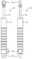
도 5는 본 고안의 구성중 실외용 업도미널 기구에 구비된 유압 실린더의 외형을 보인 정면도 및 측면도이다.Figure 5 is a front view and a side view showing the external appearance of the hydraulic cylinder provided in the outdoor up-terminal mechanism of the configuration of the present invention.
도 5를 참조하면, 본 고안의 실외용 업도미널 기구에 구비된 유압 실린더(70)는 비압축성 유체로 채워지는 이중 쳄버와, 쳄버 내에 설치되어 외부에서 인가되는 부하 하중에 의해 왕복운동을 실행하는 피스톤과, 비압축성 유체를 일방향으로 순환되도록 안내하는 유도관과, 이중 쳄버중 하나의 쳄버에 구비되어 피스톤 로드의 체적변화를 보상하기 위한 공기 튜브를 구비한 실린더 몸체부(71)과; 실린더 몸체부(71)의 일측 밑면을 기밀 상태를 유지하면서 관통하여 피스톤의 일측과 조립되어 외부로 연장 돌출된 피스톤 로드(72)와; 피스톤 로드(72)의 끝단에 고정되어 조립되는 제1 로그 앤드 베어링(73)과; 실린더 몸체부(71)의 상부 표면에 구비되어, 실린더 몸체부(71) 내에 채워지는 비압축성 유체의 압력을 조절하여 피스톤 로드(72)의 부하 하중을 다단계로 조절하기 위한 조절 노브(74)와; 피스톤 로드(72)가 관통된 실린더 몸체부(71)의 타측 끝단에 고정되어 조립되는 제2 로드 앤드 베어링(75)로 구성된다.Referring to FIG. 5, the
본 고안의 바람직한 실시 예에서는 유압 실린더(70)를 한 개만 구비시켰으나, 2개를 설치할 수 있음은 물론이고, 또한 조절 노브(74)가 한번에 11kg 씩 조절되도록 부하 하중이 설정되었다.In the preferred embodiment of the present invention, but provided with only one
이와 같이 구성된 본 고안의 실외용 업도미널 기구의 사용 동작을 첨부된 도면을 참조하여 설명하면 아래와 같다.Referring to the accompanying drawings, the operation of the outdoor up-terminal mechanism of the present invention configured as described above is as follows.
먼저, 사용자는 엉덩이를 엉덩이받이 시트(80a)에 앉히고, 등을 등받이 시트(80b)에 붙이고, 머리를 머리받이 시트(80c)에 살며시 기대고, 두 손은 한 쌍의 손잡이(60a,60b)를 잡는 준비자세를 실행한다.First, the user sits his hips on the
이어, 사용자는 손잡이(60a,60b)를 잡고 있는 상태에서, 얼굴 및 상체를 자신의 발쪽으로 향하도록 숙여주면서 손잡이(60a,60b)를 하측 방향으로 밀어주는 동작을 유지한다. 이때, 사용자의 허리와 다리는 곧게 펴주는 것이 바람직하다.Subsequently, while holding the
이때, 각각의 수평 프레임(40a,40b)의 타측의 양측 끝단부와 연결 지지대(50)의 양측 끝단부는 베어링과 베어링 샤프트를 통하여 축결합되어 있기 때문에, 사용자가 손잡이(60a,60b)를 하측 방향으로 밀어주는 동작을 유지하거나, 원래의 준비자세로 뒤돌아 가는 자세를 유지할 때 미리 설정된 각도 내에서 상하방향으로 회동운동을 실행한다.At this time, since both ends of the other side of each of the horizontal frame (40a, 40b) and both ends of the connecting
또한, 유압 실린더(70)가 연결 지지대(50)에 고정된 실린더 상측용 브라켓(51)과 프레임(30a 또는 30b)에 고정된 실린더 하측용 브라켓(31) 사이에 삽입 및 고정되어 있기 때문에, 연결 지지대(50)가 상하 방향으로 회동운동을 할 때 미리 설정된 부하 하중을 정방향 또는 역방향으로 제공한다.In addition, since the
따라서, 사용자가 준비자세에서 두 손으로 손잡이(60a,60b)를 하측 방향으로 밀어주는 동작과, 두 손으로 손잡이(60a,60b)를 상측 방향으로 끌어올리는 동작을 반복하여 실행할 때, 유압 실린더(70)가 순방향 또는 역방향으로 미리 설정된 부하 하중을 제공하기 때문에 사용자는 자신의 체력 조건 및 원하는 운동강도에 따라 복부 근육운동을 반복하여 실시한다.Therefore, when the user repeatedly executes the operation of pushing the
이때, 사용자는 이상에서 설명한 실외용 업도미널 기구의 사용전 또는 사용도중에 언제든지 간편하게 다단계의 부하 하중을 선택하여 조절하기 위한 조절 노브(74)를 조절하여 사용자가 원하는 적당한 부하 하중을 선택할 수 있다.At this time, the user can select a suitable load load desired by the user by adjusting the
따라서 사용자들은 남녀노소를 구분하지 않고도 본 고안에 따른 실외용 업도미널 기구를 이용하여 개개인의 신체적 조건이나 건강상태 그리고 원하는 운동량에 맞추어 중량부하를 조절하면서 복부 근육운동을 실행할 수 있어, 남녀노소, 성인, 노약자 등 다양한 사람들에게 사랑받는 실외 운동기구가 될 것이다.Therefore, users can execute abdominal muscle exercise by adjusting the weight load according to individual physical condition, health condition and desired exercise amount by using the outdoor up-terminal device according to the present invention without distinguishing the age and sex. It will be an outdoor sports equipment that is loved by many people, including the elderly and the elderly.
도 1은 본 고안에 바람직한 실시 예에 따른 실외용 업도미널 기구의 일 실시 예를 도시한 사시도.1 is a perspective view showing an embodiment of an up-up terminal device for outdoor use according to a preferred embodiment of the present invention.
도 2는 도 1에 보인 실외용 업도미널 기구에서 시트를 제외한 상태의 정면도.Figure 2 is a front view of the state without the seat in the outdoor up-terminal mechanism shown in FIG.
도 3은 도 1에 보인 실외용 업도미널 기구에서 시트를 제외한 상태의 측면도.Figure 3 is a side view of the state without the seat in the outdoor up-terminal mechanism shown in FIG.
도 4는 도 1 내지 도 3에 보인 실외용 업도미널 기구에서 기둥부의 배면도, 측면도, 및 평면도.Figure 4 is a rear view, side view, and plan view of the pillar portion in the outdoor up-terminal mechanism shown in Figures 1-3.
도 5는 본 고안의 바람직한 실시 예에 따른 실외용 업도미널 기구에 구비된 유압 실린더의 외형을 보인 정면도 및 측면도.Figure 5 is a front view and a side view showing the external appearance of the hydraulic cylinder provided in the outdoor up-terminal mechanism according to a preferred embodiment of the present invention.
< 도면의 주요 부분에 대한 부호의 설명 ><Description of the code | symbol about the principal part of drawing>
10 ; 기둥부 11 ; 받침대10;
12 ; 수직 프레임 13 ; 내부 보강용 브라켓12;
14 ; 전면 커버 20 ; 시트용 브라켓14;
30a,30b ; 수직 프레임 31 ; 실린더 하측용 브라켓30a, 30b;
40a,40b ; 수평 프레임 41a,41b ; 베어링 하우징40a, 40b;
43a,43b ; 고정 플랜지 50 ; 등받이 부재43a, 43b; Fixed
51a,51b : 샤프트 고정링 60a,60b ; 손잡이51a, 51b:
70 ; 유압 실린더 71 ; 실린더 몸체부70;
72 ; 피스톤 로드 73,75 ; 로드 앤드 베어링72;
74 ; 조절 노브 80a,80b,80c ; 시트74; Adjusting
Claims (3)
Translated fromKoreanPriority Applications (1)
| Application Number | Priority Date | Filing Date | Title |
|---|---|---|---|
| KR2020090002934UKR200457592Y1 (en) | 2009-03-13 | 2009-03-13 | Abdominal Machine |
Applications Claiming Priority (1)
| Application Number | Priority Date | Filing Date | Title |
|---|---|---|---|
| KR2020090002934UKR200457592Y1 (en) | 2009-03-13 | 2009-03-13 | Abdominal Machine |
Publications (2)
| Publication Number | Publication Date |
|---|---|
| KR20100001877U KR20100001877U (en) | 2010-02-22 |
| KR200457592Y1true KR200457592Y1 (en) | 2011-12-26 |
Family
ID=44449835
Family Applications (1)
| Application Number | Title | Priority Date | Filing Date |
|---|---|---|---|
| KR2020090002934UExpired - LifetimeKR200457592Y1 (en) | 2009-03-13 | 2009-03-13 | Abdominal Machine |
Country Status (1)
| Country | Link |
|---|---|
| KR (1) | KR200457592Y1 (en) |
Citations (4)
| Publication number | Priority date | Publication date | Assignee | Title |
|---|---|---|---|---|
| US20060166799A1 (en) | 2004-10-26 | 2006-07-27 | Boland Kevin O | Abdominal exercise apparatus |
| JP2006296863A (en) | 2005-04-22 | 2006-11-02 | Zaoba:Kk | Hydraulic muscle training machine |
| US7481752B2 (en) | 2006-10-03 | 2009-01-27 | Baylor University | Abdominal exercise machine |
| JP2009018099A (en) | 2007-07-13 | 2009-01-29 | Adamant Kogyo Co Ltd | Training machine for training abdominal muscle |
- 2009
- 2009-03-13KRKR2020090002934Upatent/KR200457592Y1/ennot_activeExpired - Lifetime
Patent Citations (4)
| Publication number | Priority date | Publication date | Assignee | Title |
|---|---|---|---|---|
| US20060166799A1 (en) | 2004-10-26 | 2006-07-27 | Boland Kevin O | Abdominal exercise apparatus |
| JP2006296863A (en) | 2005-04-22 | 2006-11-02 | Zaoba:Kk | Hydraulic muscle training machine |
| US7481752B2 (en) | 2006-10-03 | 2009-01-27 | Baylor University | Abdominal exercise machine |
| JP2009018099A (en) | 2007-07-13 | 2009-01-29 | Adamant Kogyo Co Ltd | Training machine for training abdominal muscle |
Also Published As
| Publication number | Publication date |
|---|---|
| KR20100001877U (en) | 2010-02-22 |
Similar Documents
| Publication | Publication Date | Title |
|---|---|---|
| CN201871160U (en) | Multi-functional exercise machine | |
| KR200463740Y1 (en) | Shoulder Machine | |
| KR200453493Y1 (en) | Leg Extentioncal Machine | |
| JP2017533753A (en) | Exercise equipment | |
| KR101827253B1 (en) | Multifunctional complex exercise equipment | |
| KR200457592Y1 (en) | Abdominal Machine | |
| US20060205575A1 (en) | Waist and belly stretching exerciser | |
| AU2004224932B2 (en) | Cardiovascular spine exerciser | |
| KR200453492Y1 (en) | Outdoor chest press mechanism | |
| KR200462291Y1 (en) | High Pully Machine | |
| EP1499399B1 (en) | Improved bath and apparatus therefor | |
| US20090054210A1 (en) | Station for Gymnastics in Water | |
| KR20100001873U (en) | Outdoor walking equipment | |
| KR20100001876U (en) | Outdoor skirting equipment | |
| CN107362499B (en) | Push-grinding abdomen building device | |
| KR20110004662U (en) | Leg exercise equipment | |
| KR20100110240A (en) | Exercise device pillar | |
| CN2338047Y (en) | Domestic multi-function device for exercising muscle | |
| KR200489544Y1 (en) | Walking and Waist Exercise Equipment | |
| KR101634065B1 (en) | Exercising apparatus for reinforce strength of legs | |
| WO2016036327A1 (en) | Portable sports equipment | |
| KR20200117469A (en) | Step fitness equipment | |
| CN220918039U (en) | Novel treadmill | |
| CN217163033U (en) | Abdominal muscle back waist body-building training device | |
| CN109350919A (en) | A multifunctional fitness equipment |
Legal Events
| Date | Code | Title | Description |
|---|---|---|---|
| A201 | Request for examination | ||
| UA0108 | Application for utility model registration | St.27 status event code:A-0-1-A10-A12-nap-UA0108 | |
| UA0201 | Request for examination | St.27 status event code:A-1-2-D10-D11-exm-UA0201 | |
| R18-X000 | Changes to party contact information recorded | St.27 status event code:A-3-3-R10-R18-oth-X000 | |
| G15R | Request for early publication | ||
| UG1501 | Laying open of application | St.27 status event code:A-1-1-Q10-Q12-nap-UG1501 | |
| R18-X000 | Changes to party contact information recorded | St.27 status event code:A-3-3-R10-R18-oth-X000 | |
| UN2301 | Change of applicant | St.27 status event code:A-3-3-R10-R13-asn-UN2301 St.27 status event code:A-3-3-R10-R11-asn-UN2301 | |
| D13-X000 | Search requested | St.27 status event code:A-1-2-D10-D13-srh-X000 | |
| D14-X000 | Search report completed | St.27 status event code:A-1-2-D10-D14-srh-X000 | |
| E902 | Notification of reason for refusal | ||
| UE0902 | Notice of grounds for rejection | St.27 status event code:A-1-2-D10-D21-exm-UE0902 | |
| E13-X000 | Pre-grant limitation requested | St.27 status event code:A-2-3-E10-E13-lim-X000 | |
| P11-X000 | Amendment of application requested | St.27 status event code:A-2-2-P10-P11-nap-X000 | |
| P13-X000 | Application amended | St.27 status event code:A-2-2-P10-P13-nap-X000 | |
| E701 | Decision to grant or registration of patent right | ||
| UE0701 | Decision of registration | St.27 status event code:A-1-2-D10-D22-exm-UE0701 | |
| REGI | Registration of establishment | ||
| UR0701 | Registration of establishment | St.27 status event code:A-2-4-F10-F11-exm-UR0701 | |
| UR1002 | Payment of registration fee | St.27 status event code:A-2-2-U10-U11-oth-UR1002 Fee payment year number:1 | |
| UG1601 | Publication of registration | St.27 status event code:A-4-4-Q10-Q13-nap-UG1601 | |
| UN2301 | Change of applicant | St.27 status event code:A-5-5-R10-R13-asn-UN2301 St.27 status event code:A-5-5-R10-R11-asn-UN2301 | |
| FPAY | Annual fee payment | Payment date:20140925 Year of fee payment:4 | |
| UR1001 | Payment of annual fee | St.27 status event code:A-4-4-U10-U11-oth-UR1001 Fee payment year number:4 | |
| FPAY | Annual fee payment | Payment date:20151126 Year of fee payment:5 | |
| UR1001 | Payment of annual fee | St.27 status event code:A-4-4-U10-U11-oth-UR1001 Fee payment year number:5 | |
| FPAY | Annual fee payment | Payment date:20160928 Year of fee payment:6 | |
| UR1001 | Payment of annual fee | St.27 status event code:A-4-4-U10-U11-oth-UR1001 Fee payment year number:6 | |
| P22-X000 | Classification modified | St.27 status event code:A-4-4-P10-P22-nap-X000 | |
| UR1001 | Payment of annual fee | St.27 status event code:A-4-4-U10-U11-oth-UR1001 Fee payment year number:7 | |
| UR1001 | Payment of annual fee | St.27 status event code:A-4-4-U10-U11-oth-UR1001 Fee payment year number:8 | |
| UC1801 | Expiration of term | St.27 status event code:N-4-6-H10-H14-oth-UC1801 Not in force date:20190314 Ip right cessation event data comment text:Termination Category : EXPIRATION_OF_DURATION | |
| R18-X000 | Changes to party contact information recorded | St.27 status event code:A-5-5-R10-R18-oth-X000 | |
| R18-X000 | Changes to party contact information recorded | St.27 status event code:A-5-5-R10-R18-oth-X000 |