KR200456718Y1 - Thermotherapy device with far-infrared radiation - Google Patents
Thermotherapy device with far-infrared radiationDownload PDFInfo
- Publication number
- KR200456718Y1 KR200456718Y1KR2020110003455UKR20110003455UKR200456718Y1KR 200456718 Y1KR200456718 Y1KR 200456718Y1KR 2020110003455 UKR2020110003455 UKR 2020110003455UKR 20110003455 UKR20110003455 UKR 20110003455UKR 200456718 Y1KR200456718 Y1KR 200456718Y1
- Authority
- KR
- South Korea
- Prior art keywords
- ceramic heater
- far
- handy
- heat
- infrared radiation
- Prior art date
- Legal status (The legal status is an assumption and is not a legal conclusion. Google has not performed a legal analysis and makes no representation as to the accuracy of the status listed.)
- Expired - Lifetime
Links
Images


Classifications
- A—HUMAN NECESSITIES
- A61—MEDICAL OR VETERINARY SCIENCE; HYGIENE
- A61F—FILTERS IMPLANTABLE INTO BLOOD VESSELS; PROSTHESES; DEVICES PROVIDING PATENCY TO, OR PREVENTING COLLAPSING OF, TUBULAR STRUCTURES OF THE BODY, e.g. STENTS; ORTHOPAEDIC, NURSING OR CONTRACEPTIVE DEVICES; FOMENTATION; TREATMENT OR PROTECTION OF EYES OR EARS; BANDAGES, DRESSINGS OR ABSORBENT PADS; FIRST-AID KITS
- A61F7/00—Heating or cooling appliances for medical or therapeutic treatment of the human body
- A61F7/007—Heating or cooling appliances for medical or therapeutic treatment of the human body characterised by electric heating
- A—HUMAN NECESSITIES
- A61—MEDICAL OR VETERINARY SCIENCE; HYGIENE
- A61H—PHYSICAL THERAPY APPARATUS, e.g. DEVICES FOR LOCATING OR STIMULATING REFLEX POINTS IN THE BODY; ARTIFICIAL RESPIRATION; MASSAGE; BATHING DEVICES FOR SPECIAL THERAPEUTIC OR HYGIENIC PURPOSES OR SPECIFIC PARTS OF THE BODY
- A61H39/00—Devices for locating or stimulating specific reflex points of the body for physical therapy, e.g. acupuncture
- A61H39/06—Devices for heating or cooling such points within cell-life limits
- G—PHYSICS
- G12—INSTRUMENT DETAILS
- G12B—CONSTRUCTIONAL DETAILS OF INSTRUMENTS, OR COMPARABLE DETAILS OF OTHER APPARATUS, NOT OTHERWISE PROVIDED FOR
- G12B1/00—Sensitive elements capable of producing movement or displacement for purposes not limited to measurement; Associated transmission mechanisms therefor
- G12B1/02—Compound strips or plates, e.g. bimetallic
- A—HUMAN NECESSITIES
- A61—MEDICAL OR VETERINARY SCIENCE; HYGIENE
- A61F—FILTERS IMPLANTABLE INTO BLOOD VESSELS; PROSTHESES; DEVICES PROVIDING PATENCY TO, OR PREVENTING COLLAPSING OF, TUBULAR STRUCTURES OF THE BODY, e.g. STENTS; ORTHOPAEDIC, NURSING OR CONTRACEPTIVE DEVICES; FOMENTATION; TREATMENT OR PROTECTION OF EYES OR EARS; BANDAGES, DRESSINGS OR ABSORBENT PADS; FIRST-AID KITS
- A61F7/00—Heating or cooling appliances for medical or therapeutic treatment of the human body
- A61F7/007—Heating or cooling appliances for medical or therapeutic treatment of the human body characterised by electric heating
- A61F2007/0071—Heating or cooling appliances for medical or therapeutic treatment of the human body characterised by electric heating using a resistor, e.g. near the spot to be heated
- A—HUMAN NECESSITIES
- A61—MEDICAL OR VETERINARY SCIENCE; HYGIENE
- A61F—FILTERS IMPLANTABLE INTO BLOOD VESSELS; PROSTHESES; DEVICES PROVIDING PATENCY TO, OR PREVENTING COLLAPSING OF, TUBULAR STRUCTURES OF THE BODY, e.g. STENTS; ORTHOPAEDIC, NURSING OR CONTRACEPTIVE DEVICES; FOMENTATION; TREATMENT OR PROTECTION OF EYES OR EARS; BANDAGES, DRESSINGS OR ABSORBENT PADS; FIRST-AID KITS
- A61F7/00—Heating or cooling appliances for medical or therapeutic treatment of the human body
- A61F2007/0086—Heating or cooling appliances for medical or therapeutic treatment of the human body with a thermostat
- A—HUMAN NECESSITIES
- A61—MEDICAL OR VETERINARY SCIENCE; HYGIENE
- A61F—FILTERS IMPLANTABLE INTO BLOOD VESSELS; PROSTHESES; DEVICES PROVIDING PATENCY TO, OR PREVENTING COLLAPSING OF, TUBULAR STRUCTURES OF THE BODY, e.g. STENTS; ORTHOPAEDIC, NURSING OR CONTRACEPTIVE DEVICES; FOMENTATION; TREATMENT OR PROTECTION OF EYES OR EARS; BANDAGES, DRESSINGS OR ABSORBENT PADS; FIRST-AID KITS
- A61F7/00—Heating or cooling appliances for medical or therapeutic treatment of the human body
- A61F2007/0093—Heating or cooling appliances for medical or therapeutic treatment of the human body programmed
- A—HUMAN NECESSITIES
- A61—MEDICAL OR VETERINARY SCIENCE; HYGIENE
- A61H—PHYSICAL THERAPY APPARATUS, e.g. DEVICES FOR LOCATING OR STIMULATING REFLEX POINTS IN THE BODY; ARTIFICIAL RESPIRATION; MASSAGE; BATHING DEVICES FOR SPECIAL THERAPEUTIC OR HYGIENIC PURPOSES OR SPECIFIC PARTS OF THE BODY
- A61H2201/00—Characteristics of apparatus not provided for in the preceding codes
- A61H2201/02—Characteristics of apparatus not provided for in the preceding codes heated or cooled
- A61H2201/0207—Characteristics of apparatus not provided for in the preceding codes heated or cooled heated
- A—HUMAN NECESSITIES
- A61—MEDICAL OR VETERINARY SCIENCE; HYGIENE
- A61H—PHYSICAL THERAPY APPARATUS, e.g. DEVICES FOR LOCATING OR STIMULATING REFLEX POINTS IN THE BODY; ARTIFICIAL RESPIRATION; MASSAGE; BATHING DEVICES FOR SPECIAL THERAPEUTIC OR HYGIENIC PURPOSES OR SPECIFIC PARTS OF THE BODY
- A61H2201/00—Characteristics of apparatus not provided for in the preceding codes
- A61H2201/02—Characteristics of apparatus not provided for in the preceding codes heated or cooled
- A61H2201/0221—Mechanism for heating or cooling
- A61H2201/0228—Mechanism for heating or cooling heated by an electric resistance element
- A—HUMAN NECESSITIES
- A61—MEDICAL OR VETERINARY SCIENCE; HYGIENE
- A61H—PHYSICAL THERAPY APPARATUS, e.g. DEVICES FOR LOCATING OR STIMULATING REFLEX POINTS IN THE BODY; ARTIFICIAL RESPIRATION; MASSAGE; BATHING DEVICES FOR SPECIAL THERAPEUTIC OR HYGIENIC PURPOSES OR SPECIFIC PARTS OF THE BODY
- A61H2201/00—Characteristics of apparatus not provided for in the preceding codes
- A61H2201/10—Characteristics of apparatus not provided for in the preceding codes with further special therapeutic means, e.g. electrotherapy, magneto therapy or radiation therapy, chromo therapy, infrared or ultraviolet therapy
- A—HUMAN NECESSITIES
- A61—MEDICAL OR VETERINARY SCIENCE; HYGIENE
- A61H—PHYSICAL THERAPY APPARATUS, e.g. DEVICES FOR LOCATING OR STIMULATING REFLEX POINTS IN THE BODY; ARTIFICIAL RESPIRATION; MASSAGE; BATHING DEVICES FOR SPECIAL THERAPEUTIC OR HYGIENIC PURPOSES OR SPECIFIC PARTS OF THE BODY
- A61H2201/00—Characteristics of apparatus not provided for in the preceding codes
- A61H2201/12—Driving means
- A61H2201/1207—Driving means with electric or magnetic drive
- A—HUMAN NECESSITIES
- A61—MEDICAL OR VETERINARY SCIENCE; HYGIENE
- A61H—PHYSICAL THERAPY APPARATUS, e.g. DEVICES FOR LOCATING OR STIMULATING REFLEX POINTS IN THE BODY; ARTIFICIAL RESPIRATION; MASSAGE; BATHING DEVICES FOR SPECIAL THERAPEUTIC OR HYGIENIC PURPOSES OR SPECIFIC PARTS OF THE BODY
- A61H2201/00—Characteristics of apparatus not provided for in the preceding codes
- A61H2201/50—Control means thereof
- A61H2201/5023—Interfaces to the user
- A—HUMAN NECESSITIES
- A61—MEDICAL OR VETERINARY SCIENCE; HYGIENE
- A61H—PHYSICAL THERAPY APPARATUS, e.g. DEVICES FOR LOCATING OR STIMULATING REFLEX POINTS IN THE BODY; ARTIFICIAL RESPIRATION; MASSAGE; BATHING DEVICES FOR SPECIAL THERAPEUTIC OR HYGIENIC PURPOSES OR SPECIFIC PARTS OF THE BODY
- A61H2201/00—Characteristics of apparatus not provided for in the preceding codes
- A61H2201/50—Control means thereof
- A61H2201/5058—Sensors or detectors
- A61H2201/5082—Temperature sensors
- A—HUMAN NECESSITIES
- A61—MEDICAL OR VETERINARY SCIENCE; HYGIENE
- A61N—ELECTROTHERAPY; MAGNETOTHERAPY; RADIATION THERAPY; ULTRASOUND THERAPY
- A61N5/00—Radiation therapy
- A61N5/06—Radiation therapy using light
- A61N2005/0658—Radiation therapy using light characterised by the wavelength of light used
- A61N2005/0659—Radiation therapy using light characterised by the wavelength of light used infrared
- A61N2005/066—Radiation therapy using light characterised by the wavelength of light used infrared far infrared
Landscapes
- Health & Medical Sciences (AREA)
- Veterinary Medicine (AREA)
- Public Health (AREA)
- Rehabilitation Therapy (AREA)
- General Health & Medical Sciences (AREA)
- Life Sciences & Earth Sciences (AREA)
- Animal Behavior & Ethology (AREA)
- Physical Education & Sports Medicine (AREA)
- Epidemiology (AREA)
- Pain & Pain Management (AREA)
- Engineering & Computer Science (AREA)
- Biomedical Technology (AREA)
- Heart & Thoracic Surgery (AREA)
- Vascular Medicine (AREA)
- Radiation-Therapy Devices (AREA)
Abstract
Translated fromKoreanDescription
Translated fromKorean본 고안은 세라믹히터가 설치된 온열치료기의 내부 중 세라믹히터와 온열치료기의 배면 쪽 사이에 방사되는 열을 차단시켜 주는 단열 부재가 구비되어 원적외선 온열치료기의 배면 쪽으로 방사되는 열을 차단시켜 줌으로써, 안전사고의 발생을 사전에 차단시켜 줌과 더불어, 원적외선 방사부재에는 세라믹 코팅재가 도포되고, 단열부재에는 일라이트(Illite)가 도포되어 원적외선 방사효율을 극대화시켜주는 원적외선 온열치료기에 관한 것이다.
The present invention is provided with a heat insulating member that blocks heat radiated between the ceramic heater and the back side of the heat treatment device inside the heat treatment device installed with the ceramic heater to block the heat radiated toward the back side of the far infrared heat treatment device, thereby safety In addition to blocking the occurrence of the in advance, the far-infrared radiation member is coated with a ceramic coating material, and the insulating member is applied to the far-infrared heat treatment device to maximize the far-infrared radiation efficiency.
일반적으로, 가정이나 특정장소(일예로, 병원)에서 사용되고 있는 온열치료기는 환부에 접촉하여 고온의 열을 전달함으로써 근육 결림, 근육통, 신경통, 내장질환, 만성변비 등의 치료 내지 고통의 완화에 사용되는 장치이다.In general, the thermotherapy device used at home or in a specific place (for example, a hospital) is used for treating or relieving pain such as muscle stiffness, muscle pain, neuralgia, visceral disease, and chronic constipation by contacting the affected part and transferring high temperature heat. Device.
그리고, 최근에는 세라믹부재를 사용하여 원적외선을 방사시키는 온열치료기가 제안되고 있는데, 이처럼 온열치료기에서 방사되는 원적외선에 의해 신체를 따뜻하게 하는 것은 물론 근육의 긴장을 완화시켜 주고, 환부의 동통(疼痛)을 부드럽게 하여, 신진대사를 촉진시켜 세포를 활성화 시켜주는 효능이 있다고 알려져 있다.In recent years, a thermotherapy device that emits far-infrared rays using a ceramic member has been proposed. In this way, the infrared radiation emitted from the heat-treatment device not only warms the body but also relaxes muscle tension and reduces pain in the affected area. It is known to have the effect of activating cells by softening and promoting metabolism.
그런데 이러한 효능을 제공하는 온열치료기의 경우 휴대가 불편한 문제점이 있었는데 선출원된 온열치료기(출원번호; 10-2002-0062015)에 의해 해소되었다.By the way, the thermal therapy device that provides such efficacy had a problem inconvenient to carry, was solved by the pre-applied thermal therapy device (application number; 10-2002-0062015).
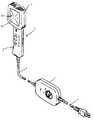
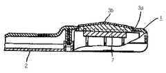
도 1은 종래의 온열치료기를 나타낸 외관사시도이고, 도 2는 종래의 온열치료기의 구성 중 온열치료기 본체를 나타낸 요부평면도이며, 도 3은 종래의 온열치료기의 구성 중 온열치료기 본체를 나타낸 요부측단면도이다.1 is an external perspective view showing a conventional heat treatment device, Figure 2 is a main plan view showing the main body of the heat treatment device of the conventional heat treatment device, Figure 3 is a main side cross-sectional view showing the body of the heat treatment device of the conventional heat treatment device. to be.
도시된 바와 같이, 종래의 온열치료기는 경량의 핸디타입인 것으로, 파지부(2)와 원적외선 방사부(3)로 이루어지는 온열치료기 본체(1), 온열치료기 본체(1)와 접속코드(4)를 개재하여 접속된 온도의 제어부(5), 제어부(5)와 전원을 접속하는 전원코드(6)로 이루어져 있다.As shown, the conventional heat treatment machine is a lightweight handy type, the heat treatment body main body (1) consisting of the gripping portion (2) and the far infrared radiation unit (3), the heat treatment body (1) and the connecting cord (4) It consists of a control part 5 of the temperature connected via the power supply cord 6 which connects the control part 5 and a power supply.
여기서, 온열치료기 본체(1) 중 방사부(3) 쪽 내부에는 3개의 세라믹히터(7)와 온도센서(8)가 설치되어 있고, 방사부(3)는 온열치료기 본체(1)의 개구(3a)된 부분에 원적외선 방사판(3b)이 부착된 구조를 갖는다.Here, three
이러한 구성을 갖는 종래의 온열치료기는 전원스위치의 구동조작을 통해 전원스위치의 구동조작이 요청되면 제어부(5)에는 전원코드(6)로부터 상용전원이 공급되고, 그 공급되는 상용전원은 접속코드(4)를 통해 온열치료기 본체(1)의 내부에 설치된 3개의 세라믹히터(7)에 공급되어 3개의 세라믹히터(7)가 가열되면서 원적외선도 방사된다.In the conventional thermal therapy apparatus having such a configuration, when a driving operation of the power switch is requested through the driving operation of the power switch, the control unit 5 is supplied with commercial power from the power cord 6, and the commercial power supplied is connected to the connection cord ( 4) is supplied to the three
이용자는 원하는 온도까지 가열되면 핸디타입인 온열치료기 본체(1)의 파지부(2)를 잡고 치료하고자 하는 환부에 원적외선 방사판(3b)의 접촉을 통해 고온의 열 및 원적외선이 전달되어 온열치료를 수행한다.
When the user heats up to the desired temperature, the user grasps the holding
그러나 이와 같은 이점에도 불구하고, 종래의 온열치료기는 다음과 같은 문제점이 있다.However, in spite of these advantages, the conventional thermal therapy device has the following problems.
종래의 온열치료기를 구성하는 온열치료기 본체(1)의 내부에 설치된 3개의 세라믹히터(7)는 도면에 도시된 것처럼 온열치료기 본체(1)의 내부 바닥에 일체로 구비된 거치대에 거치되어 고정된 구조이며, 거치대를 통해 거치된 세라믹히터(7)와 온열치료기 본체(1) 사이에는 텅빈 공간으로 이루어져 있기 때문에 3개의 세라믹히터(7)에서 방사되는 열은 육면체 형상을 갖는 세라믹히터(7)의 전면을 통해 방사됨으로써, 원적외선 방사판(3b) 쪽뿐만 아니라 원적외선 방사판(3b)의 반대쪽인 온열치료기 본체(1)의 배면 쪽으로도 세라믹히터(7)를 통해 열이 방사되는데 이때, 방사되는 열은 고온의 열이기 때문에 핸디타입의 특성상 이용자가 온열치료기 본체(1)의 파지부(2)를 잡고 치료 중 다른 신체 부분에 온열치료기 본체(1) 배면 쪽이 접촉될 수 있어 안전사고를 야기시키는 위험성을 내포하고 있다.Three
이 때문에, 온열치료기 본체(1)의 내부에 설치된 세라믹히터(7)와 온열치료기 본체(1) 사이에 방사되는 열을 차단시켜주는 구조의 필요성이 대두되었다.
For this reason, the necessity of the structure which blocks the heat radiated between the
본 고안은 상기 종래기술의 문제점을 해결하기 위한 것으로, 본 고안의 목적은 세라믹히터가 설치된 온열치료기의 내부 중 세라믹히터와 온열치료기의 배면 쪽 사이에 방사되는 열을 차단시켜주는 단열 부재가 구비된 원적외선 온열치료기를 제공하는데 있다.The present invention is to solve the problems of the prior art, an object of the present invention is provided with a heat insulating member for blocking heat radiated between the ceramic heater and the back side of the heat treatment device of the inside of the heat treatment device installed ceramic heater. To provide a far infrared heat treatment device.
본 고안을 달성하기 위한 기술적 사상으로 본 고안의 원적외선 온열치료기는, 손잡이가 일체로 연결된 것으로, 일측면에 원적외선 방사부재가 설치된 핸디형 몸체와; 상기 원적외선 방사부재가 설치된 핸디형 몸체 쪽의 내부에 설치되는 것으로, 공급되는 전원에 의해 가열과 함께 원적외선을 방사하는 세라믹 히터와; 상기 핸디형 몸체의 내부 중 상기 세라믹히터와 상기 핸디형 몸체의 배면 쪽 사이에 구비되어 상기 세라믹히터가 설치된 상기 핸디형 몸체의 배면 쪽으로 방사되는 열을 차단시켜 주는 단열부재와; 상기 핸디형 몸체의 세라믹 히터 쪽과 접속코드를 통해 연결되는 것으로 온/오프 및 온도 조절을 제어하는 컨트롤러;로 이루어진다.As a technical idea for achieving the present invention, the far-infrared heat therapy device of the present invention, the handle is integrally connected, the handy body and the far-infrared radiation member is installed on one side; A ceramic heater installed inside the handy-type body side in which the far-infrared radiation member is installed, and radiating far-infrared radiation with heating by a power supply; An insulation member provided between the ceramic heater and the rear side of the handy body in the handy body to block heat radiated toward the rear side of the handy body in which the ceramic heater is installed; It is connected to the ceramic heater side of the handy body through a connection cord to the controller for controlling the on / off and temperature control.
상기 단열부재는 부직포이거나, 실리콘 패드이거나 또는 부직포와 실리콘 패드가 적층되어 이루어진 것 중 어느 하나를 선택하여 사용할 수 있다.The heat insulating member may be selected from the group consisting of a nonwoven fabric, a silicon pad, or a nonwoven fabric and a silicon pad laminated.
상기 핸디형 몸체의 배면 쪽에 위치하는 상기 실리콘 패드의 일면에는 단열고무가 도포된다.Insulating rubber is applied to one surface of the silicon pad located on the rear side of the handy body.
상기 단열부재에는 일라이트(illite)가 도포된다.An illite is coated on the heat insulating member.
본 고안의 원적외선 온열치료기에는, 상기 세라믹히터 부근에 설치되어 방열온도를 감지하는 온도감지센서와; 상기 세라믹히터에 공급되는 전원을 차단하는 바이메탈과; 상기 세라믹히터가 고정되는 것으로, 상기 세라믹히터, 상기 온도감지센서 및 상기 바이메탈과 회로적으로 연결되는 것으로, 상기 세라믹히터를 고정시켜 주는 히터지지용 회로기판;을 포함하고, 상기 컨트롤러는 상기 온도감지센서로부터 감지되는 방열온도를 참조하여 상기 세라믹히터가 설정된 온도를 초과하면 상기 바이메탈이 상기 세라믹히터로 공급되는 전원을 차단하도록 제어한다.The far-infrared heat treatment device of the present invention comprises: a temperature sensing sensor installed near the ceramic heater and sensing a heat radiation temperature; A bimetal for cutting off power supplied to the ceramic heater; And a heater supporting circuit board to fix the ceramic heater, the circuit heater being connected to the ceramic heater, the temperature sensor and the bimetal in a circuit, to fix the ceramic heater. The bimetal controls to cut off power supplied to the ceramic heater when the ceramic heater exceeds the set temperature with reference to the heat radiation temperature detected by the sensor.
상기 히터지지용 회로기판과 상기 접속코드는 컨넥터를 통해 연결되는 구조이다.
The heater supporting circuit board and the connection cord are connected through a connector.
본 고안은 세라믹히터가 설치된 온열치료기의 내부 중 세라믹히터와 온열치료기의 배면 쪽 사이에 방사되는 열을 차단시켜 주는 단열 부재가 구비되어 원적외선 온열치료기의 배면 쪽으로 방사되는 열을 차단시켜 줌으로써, 안전사고의 발생을 사전에 차단시켜 주는 효과를 발휘한다.The present invention is provided with a heat insulating member that blocks heat radiated between the ceramic heater and the back side of the heat treatment device inside the heat treatment device installed with the ceramic heater to block the heat radiated toward the back side of the far infrared heat treatment device, thereby safety It is effective in blocking the occurrence of.
또한, 본 고안은 원적외선 방사부재에는 세라믹 코팅재가 도포되고, 단열부재에는 일라이트(Illite)가 도포되어 원적외선 방사효율을 극대화시켜주는 효과도 있다.
In addition, the present invention has a ceramic coating material is applied to the far-infrared radiation member, the illite (Illite) is applied to the heat insulating member has the effect of maximizing the far infrared radiation efficiency.
도 1은 종래의 온열치료기를 나타낸 외관사시도,
도 2는 종래의 온열치료기의 구성 중 온열치료기 본체를 나타낸 요부평면도,
도 3은 종래의 온열치료기의 구성 중 온열치료기 본체를 나타낸 요부측단면도,
도 4는 본 고안의 원적외선 온열치료기를 나타낸 외관사시도,
도 5는 본 고안의 원적외선 온열치료기를 나타낸 분해사시도,
도 6은 본 고안의 원적외선 온열치료기의 구성 중 핸디형 몸체를 나타낸 요부평면도,
도 7은 본 고안의 원적외선 온열치료기의 구성 중 히터지지용 회로기판 쪽을 나타낸 평면도이다.1 is an external perspective view showing a conventional heat treatment device,
Figure 2 is a plan view of the main part showing the main body of the heat treatment device of the conventional heat treatment device,
Figure 3 is a main sectional side view showing the main body of the thermotherapy unit of the conventional thermotherapy unit,
Figure 4 is an external perspective view showing a far infrared thermal therapy device of the present invention,
5 is an exploded perspective view showing a far infrared thermal therapy device of the present invention,
Figure 6 is a plan view of the main part showing the handy body of the far infrared thermal therapy device of the present invention,
Figure 7 is a plan view showing a heater supporting circuit board of the configuration of the far infrared thermal treatment device of the present invention.
이하에서는 본 고안의 실시예의 구성 및 작용에 대하여 첨부한 도면을 참조하면서 상세히 설명하기로 한다.Hereinafter, with reference to the accompanying drawings for the configuration and operation of the embodiment of the present invention will be described in detail.
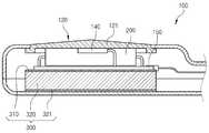
도 4는 본 고안의 원적외선 온열치료기를 나타낸 외관사시도이고, 도 5는 본 고안의 원적외선 온열치료기를 나타낸 분해사시도이며, 도 6은 본 고안의 원적외선 온열치료기의 구성 중 핸디형 몸체를 나타낸 요부평면도이고, 도 7은 본 고안의 원적외선 온열치료기의 구성 중 히터지지용 회로기판 쪽을 나타낸 평면도이다.Figure 4 is an external perspective view showing a far infrared heat treatment device of the present invention, Figure 5 is an exploded perspective view showing a far infrared heat treatment device of the present invention, Figure 6 is a plan view of the main body of the handy body of the configuration of the far infrared heat treatment device of the present invention, Figure 7 is a plan view showing a heater supporting circuit board of the configuration of the far infrared thermal treatment device of the present invention.
도시된 바와 같이, 본 고안의 원적외선 온열치료기는 크게 핸디형 몸체(100), 세라믹 히터(200), 단열부재(300), 컨트롤러(400)로 이루어진다.As shown, the far-infrared heat therapy device of the present invention is largely made of a
먼저, 핸디형 몸체(100)는 손잡이(110)가 일체로 연결된 것으로, 일측면에 원적외선 방사부재(120)가 설치된 부재이다.First, the
여기서, 원적외선 방사부재(120)는 원적외선 방사판(121) 및 그 원적외선 방사판(121)이 안착될 수 있게 핸디형 몸체(100)에 개방형성되는 안착공간(122)으로 이루어진다.Here, the far
또한, 원적외선 방사판(121)에는 아래에 언급되는 세라믹 히터(200)로부터 전달되는 열에 의해 원적외선 및 음이온을 방출하는 세라믹 코팅재가 코팅되어 제공하는 것이 바람직하다. 이처럼, 원적외선 방사판(121)에 코팅되는 세라믹 코팅재에 포함되는 조성물은 세라믹 분말, 토르말린 분말 및 페인트 등이 혼합되어 제공될 수 있으며, 180~600℃에서 가열함으로써 코팅처리된다.In addition, it is preferable that the far
또한, 핸디형 몸체(100)의 내부 바닥면에는 아래에서 언급되는 단열부재(300)가 움직이지 않게 한 쌍의 이동방지벽(101)이 설치제공된다.In addition, a pair of
상기 세라믹 히터(200)는 원적외선 방사부재(120)가 설치된 핸디형 몸체(100) 쪽의 내부에 설치되는 것으로, 공급되는 전원에 의해 가열과 함께 원적외선을 방사하는 부재로서, 알루미나(Al2O3)를 주성분으로 포함하는 복합 세라믹 재질이며, 내부에 저항 발열체가 구비되어, 저항 발열체의 발열에 의해 간접 가열되면서 원적외선이 방사되는 구조를 갖는다.The
이러한 기능을 제공하는 세라믹 히터(200)의 개수는 도면에 도시된 것처럼, 3개일 수 있으며, 이러한 세라믹 히터(200)의 개수는 사용목적이나 효과 또는 구매자의 요구조건을 충족하기 위하여 가감조절되어 제공될 수 있다.The number of
이와 더불어, 세라믹 히터(200)는 히터지지용 회로기판(150)에 회로적으로 연결되어 고정되는데 이처럼, 세라믹 히터(200)는 히터지지용 회로기판(150)에는 온도감지센서(130)나 바이메탈(140)도 회로적으로 연결되어 고정될 수 있다.In addition, the
여기서, 히터지지용 회로기판(150)에 회로적으로 연결되어 고정되는 온도감지센서(130)는 세라믹히터(200)에서 방사되는 방열온도를 감지하는 부재로서, 서미스터를 이용할 수 있다.Here, the
그리고 히터지지용 회로기판(150)에 회로적으로 연결되어 고정되는 바이메탈(140)은 세라믹히터(200)에 공급되는 전원을 차단하는 부재로서, 아래에서 언급되는 컨트롤러(400)를 통해 온도감지센서(130)로부터 감지되는 세라믹히터(200)의 방열온도를 참조하여 세라믹히터(200)가 설정된 온도를 초과하면 바이메탈(140)이 세라믹히터(200)로 공급되는 전원을 차단하도록 제어함으로써, 사용 중 설정온도 초과에 따른 안전사고 등을 사전에 차단하여 주는 기능을 수행한다.In addition, the
이와 더불어, 세라믹히터(200), 바이메탈(140) 및 온도감지센서(130)와 회로적으로 연결되는 히터지지용 회로기판(150)과 아래에 언급되는 컨트롤러(400)의 접속코드(102) 사이는 컨넥터(160)를 통해 연결되는데 이처럼, 연결되는 컨넥터(160)의 구성은 다양한 적용예를 적용할 수 있는데 도면에 도시된 것처럼 암수의 핀으로 이루어진 접합부(161)와 금속단자(162)가 적용되거나 또는 도면에 도시하지는 않았지만 암수의 잭을 적용할 수도 있다.In addition, between the
상기 단열부재(300)는 핸디형 몸체(100)의 내부 중 세라믹히터(200)가 고정된 히터지지용 회로기판(150)과 핸디형 몸체(100)의 배면 쪽 사이에 구비되어 세라믹히터(200)가 설치된 핸디형 몸체(100)의 배면 쪽으로 방사되는 열을 차단시켜 주는 기능을 수행하는 부재이다.The
이러한 기능을 수행하는 단열부재(300)의 구성은 부직포(310)나 실리콘 패드(320) 중 어느 하나를 선택하여 사용하거나 또는, 단열기능이 극대화될 수 있도록 부직포(310)와 실리콘 패드(320)를 적층하여 사용할 수 있다.The configuration of the
추가적으로, 핸디형 몸체(100)의 배면 쪽에 위치하는 실리콘 패드(320)의 일면에는 단열성이 우수한 단열도료인 단열고무(321)를 도포시켜 적층시키는데 이처럼 실리콘 패드(320)의 일면에 도포되어 적층되는 단열고무(321)는 단열성이 우수한 도료인 라텍스를 이용하는 것이 바람직하다.In addition, one surface of the
또한, 단열부재(300)인 부직포(310) 및 실리콘 패드(320)에는 원적외선 방사 및 음인온 발생 등에 뛰어난 특성을 지닌 일라이트(Illite)를 도포하여 원적외선 방사효율을 보다 극대화시켜 준다.In addition, the
이처럼, 단열부재(300)인 부직포(310) 및 실리콘 패드(320)에 도포되는 일라이트는 단사정계에 속하는 운모족 광물로서, 굳기가 1~2, 비중이 2.6~2.9, 조흔색은 백색으로, 화학성분과 결정구조로 보아 다른 성분을 포함하고 있는 혼합광물이다As such, the illite applied to the
상기 컨트롤러(400)는 핸디형 몸체(100)의 세라믹 히터(200) 쪽과 접속코드(102)를 통해 연결되고, 전원공급원 쪽과 전원코드(401)를 통해 연결된 것으로 핸디형 몸체(100)의 작동을 위한 온열 온/오프 제어, 온열 온도 증가 및 감소를 위한 온도 조절을 제어하는 부재이다, 여기서, 전원코드(401) 쪽과 연결되는 전원공급원은 220V의 상용전원을 이용할 수 있다.The
이러한 기능을 수행하는 컨트롤러(400)의 전면에는 핸디형 몸체(100)의 작동을 위한 온/오프 버튼이 구비되어, 그 구비되는 핸디형 몸체(100)의 작동을 위한 온/오프 버튼을 조작하면, 컨트롤러(400)는 전원공급원에서 전원코드(401)를 통해 공급되는 전원을 접속코드(102) 쪽으로 통전되게 제어하여 세라믹히터(200)에 전원을 공급함으로써 발열되게 한다.The front of the
또한,컨트롤러(400)의 전면에는 핸디형 몸체(100)의 세라믹히터(200)의 발열되는 온열온도를 가감 조절하는 온열온도 증가/감소버튼이 구비되어, 그 구비되는 온열온도 증가/감소버튼을 조작하면 컨트롤러(400)는 세라믹히터(200) 쪽으로 공급되는 전원의 양을 조절하여 온열온도가 증가되거나 감소되도록 제어한다.In addition, the front of the
또한,컨트롤러(400)의 전면에는 사용자가 온열온도 증가/감소버튼의 조작을 통해 설정되는 온도를 표시하는 설정온도 표시부 및 현재 세라믹히터(200)에서 발열되는 온열온도를 나타내는 현재온도 표시부를 구비하여, 컨트롤러(400)에서 설정온도 및 현재온도가 표시되도록 제어함으로서, 사용자가 인지할 수 있게 제공한다.In addition, the front of the
또한,컨트롤러(400)의 전면에는 사용자가 온열치료기의 1시간 사용에 따른 잔존시간을 나타내는 잔존시간 표시부도 구비되어, 컨트롤러(400)에서 온열치료기의 1시간 사용에 따른 잔존시간이 표시되도록 제어함으로서, 사용자가 인지할 수 있게 제공한다.
In addition, the front of the
1 : 온열치료기 본체2 : 파지부
3 : 원적외선 방사부3a : 개구
3b : 원적외선 방사판4,102 : 접속코드
5 : 제어부(5), 6,401 : 전원코드
7,200 : 세라믹히터100 : 핸디형 몸체
101 : 이동방지벽110 손잡이
120 : 원적외선 방사부재121 : 원적외선 방사판
122 : 안착공간130 : 온도감지센서
140 : 바이메탈150 : 히터지지용 회로기판
160 : 컨넥터161 : 접합부
162 : 금속단자300 : 단열부재
310 : 부직포320 : 실리콘 패드
321 : 단열고무400 : 컨트롤러1: Body of heat treatment device 2: Holding part
3: far-
3b: Far infrared radiation plate 4,102: connection cord
5: control unit (5), 6,401: power cord
7,200: ceramic heater 100: handy body
101: 110 movement barrier
120: far infrared radiation member 121: far infrared radiation plate
122: seating space 130: temperature sensor
140: bimetal 150: heater supporting circuit board
160: connector 161: junction
162: metal terminal 300: heat insulating member
310: nonwoven fabric 320: silicon pad
321: insulating rubber 400: controller
Claims (8)
Translated fromKorean상기 원적외선 방사부재(120)가 설치된 핸디형 몸체(100) 쪽의 내부에 설치되는 것으로, 공급되는 전원에 의해 가열과 함께 원적외선을 방사하는 세라믹 히터(200)와;
상기 핸디형 몸체(100)의 내부 중 상기 세라믹히터(200)와 상기 핸디형 몸체(100)의 배면 쪽 사이에 구비되어 상기 세라믹히터(200)가 설치된 상기 핸디형 몸체(100)의 배면 쪽으로 방사되는 열을 차단시켜 주는 단열부재(300)와;
상기 핸디형 몸체(100)의 세라믹 히터(200) 쪽과 접속코드(102)를 통해 연결되는 것으로 온/오프 및 온도 조절을 제어하는 컨트롤러(400);로 이루어지되,
상기 단열부재(300)는 부직포(310)와 실리콘 패드(320)가 적층되어 이루어지고,
상기 핸디형 몸체(100)의 배면 쪽에 위치하는 상기 실리콘 패드(320)의 일면에는 단열고무(321)가 도포되며,
상기 단열부재(300)에는 일라이트(illite)가 도포되고, 된 것을 특징으로 하는 원적외선 온열치료기.
The handle 110 is integrally connected, the handy body 100 is installed with a far-infrared radiation member 120 on one side;
A ceramic heater 200 installed inside the handy-type body 100 in which the far-infrared radiation member 120 is installed, and radiating far-infrared radiation with heating by a supplied power;
The heat inside the handy body 100 is provided between the ceramic heater 200 and the rear side of the handy body 100 to radiate heat toward the rear surface of the handy body 100 in which the ceramic heater 200 is installed. Insulating member 300 for blocking;
Consists of being connected via the ceramic heater 200 side and the connection cord 102 of the handy-type body 100, the controller 400 for controlling the on / off and temperature control;
The heat insulation member 300 is made of a non-woven fabric 310 and the silicon pad 320 is laminated,
Insulating rubber 321 is applied to one surface of the silicon pad 320 located on the rear side of the handy body 100,
Far infrared heat treatment device, characterized in that the insulating member 300 is coated with an illite (illite).
상기 세라믹히터(200) 부근에 설치되어 방열온도를 감지하는 온도감지센서(130)와;
상기 세라믹히터(200)에 공급되는 전원을 차단하는 바이메탈(140)과;
상기 세라믹히터(200)가 고정되는 것으로, 상기 세라믹히터(200), 상기 온도감지센서(130) 및 상기 바이메탈(140)과 회로적으로 연결되는 것으로, 상기 세라믹히터(200)를 고정시켜 주는 히터지지용 회로기판(150);을 포함하고,
상기 컨트롤러(400)는 상기 온도감지센서(130)로부터 감지되는 방열온도를 참조하여 상기 세라믹히터(200)가 설정된 온도를 초과하면 상기 바이메탈(140)이 상기 세라믹히터(200)로 공급되는 전원을 차단하도록 제어하는 것을 특징으로 하는 원적외선 온열치료기.
The method of claim 1,
A temperature detection sensor 130 installed near the ceramic heater 200 to detect a heat radiation temperature;
A bimetal 140 for interrupting power supplied to the ceramic heater 200;
The ceramic heater 200 is fixed to the heater, which is connected to the ceramic heater 200, the temperature sensor 130 and the bimetal 140 in a circuit, fixing the ceramic heater 200. Support circuit board 150; including,
The controller 400 refers to the heat radiation temperature detected by the temperature sensor 130, when the ceramic heater 200 exceeds the set temperature, the bimetal 140 supplies power supplied to the ceramic heater 200. Far infrared thermal therapy apparatus, characterized in that the control to block.
상기 히터지지용 회로기판(150)과 상기 접속코드(102)는 컨넥터(160)를 통해 연결되는 것을 특징으로 하는 원적외선 온열치료기.The method of claim 7, wherein
The heater support circuit board 150 and the connection cord 102 is far infrared thermal therapy apparatus, characterized in that connected through the connector (160).
Priority Applications (1)
| Application Number | Priority Date | Filing Date | Title |
|---|---|---|---|
| KR2020110003455UKR200456718Y1 (en) | 2011-04-22 | 2011-04-22 | Thermotherapy device with far-infrared radiation |
Applications Claiming Priority (1)
| Application Number | Priority Date | Filing Date | Title |
|---|---|---|---|
| KR2020110003455UKR200456718Y1 (en) | 2011-04-22 | 2011-04-22 | Thermotherapy device with far-infrared radiation |
Publications (1)
| Publication Number | Publication Date |
|---|---|
| KR200456718Y1true KR200456718Y1 (en) | 2011-11-14 |
Family
ID=53676271
Family Applications (1)
| Application Number | Title | Priority Date | Filing Date |
|---|---|---|---|
| KR2020110003455UExpired - LifetimeKR200456718Y1 (en) | 2011-04-22 | 2011-04-22 | Thermotherapy device with far-infrared radiation |
Country Status (1)
| Country | Link |
|---|---|
| KR (1) | KR200456718Y1 (en) |
Cited By (8)
| Publication number | Priority date | Publication date | Assignee | Title |
|---|---|---|---|---|
| KR200467159Y1 (en) | 2012-11-13 | 2013-05-29 | 김철민 | Ion heating machine for hair or scalp care |
| KR101412997B1 (en)* | 2012-11-05 | 2014-07-04 | 조동식 | Manufacturing method of thermal therapy apparatus |
| KR101564685B1 (en)* | 2013-03-08 | 2015-11-02 | 조병석 | Small heating therapy device |
| CN109820489A (en)* | 2019-04-04 | 2019-05-31 | 深圳光秀医疗科技有限公司 | A skin detection device |
| KR20210054865A (en) | 2019-11-06 | 2021-05-14 | 상운메디칼(주) | An treatment apparatus using far-infrared radiation |
| KR102286259B1 (en)* | 2020-03-31 | 2021-08-06 | 박달원 | Skin and scalp care |
| CN114146318A (en)* | 2021-11-08 | 2022-03-08 | 广东省医疗器械质量监督检验所 | Testing device and method of frequency spectrum therapeutic apparatus |
| KR102590417B1 (en)* | 2023-03-22 | 2023-10-17 | 이상진 | far-infrared raying heating apparatus |
- 2011
- 2011-04-22KRKR2020110003455Upatent/KR200456718Y1/ennot_activeExpired - Lifetime
Cited By (9)
| Publication number | Priority date | Publication date | Assignee | Title |
|---|---|---|---|---|
| KR101412997B1 (en)* | 2012-11-05 | 2014-07-04 | 조동식 | Manufacturing method of thermal therapy apparatus |
| KR200467159Y1 (en) | 2012-11-13 | 2013-05-29 | 김철민 | Ion heating machine for hair or scalp care |
| KR101564685B1 (en)* | 2013-03-08 | 2015-11-02 | 조병석 | Small heating therapy device |
| CN109820489A (en)* | 2019-04-04 | 2019-05-31 | 深圳光秀医疗科技有限公司 | A skin detection device |
| KR20210054865A (en) | 2019-11-06 | 2021-05-14 | 상운메디칼(주) | An treatment apparatus using far-infrared radiation |
| KR102337645B1 (en) | 2019-11-06 | 2022-01-06 | 상운메디칼(주) | An treatment apparatus using far-infrared radiation |
| KR102286259B1 (en)* | 2020-03-31 | 2021-08-06 | 박달원 | Skin and scalp care |
| CN114146318A (en)* | 2021-11-08 | 2022-03-08 | 广东省医疗器械质量监督检验所 | Testing device and method of frequency spectrum therapeutic apparatus |
| KR102590417B1 (en)* | 2023-03-22 | 2023-10-17 | 이상진 | far-infrared raying heating apparatus |
Similar Documents
| Publication | Publication Date | Title |
|---|---|---|
| KR200456718Y1 (en) | Thermotherapy device with far-infrared radiation | |
| US10369043B2 (en) | Multi-layer heating mat for providing therapeutic heat to an area of the body | |
| JP2013056023A (en) | Hair iron | |
| KR20100134366A (en) | Urethane Fever Health Pad Using Activated Carbon Carbon Fiber | |
| TWI517846B (en) | Skin treatment apparatus usable for vibration message including self-regulating heater | |
| KR102080560B1 (en) | Heating structure and manufacturing method thereof | |
| KR101546634B1 (en) | Apparatus For Hot-heat and Laser Fomentation | |
| KR20070112903A (en) | Customized Far Infrared Radiation Plane Heat Sheet | |
| KR101658992B1 (en) | Electric Heating Mat | |
| JP3137911U (en) | Electric water heater | |
| KR101649266B1 (en) | Far-infrared irradiation as the heat storage fomenting device | |
| KR200454760Y1 (en) | Jade steam machine with far infrared radiation | |
| JP3136038U (en) | Human body part heating device | |
| KR20090049107A (en) | Portable Heater Using Far Infrared Radiation Material | |
| KR200410058Y1 (en) | Portable thermal therapy device that improves blood circulation in the human body using spinning electromagnetic radiation | |
| KR200295893Y1 (en) | A jade type fomentation apparatus | |
| KR200415717Y1 (en) | Gel Thermal Mat | |
| KR200320968Y1 (en) | A thermic mat | |
| JP3218333U (en) | Thermal therapy device | |
| KR102727768B1 (en) | Fancy mattress with heating pad | |
| KR200489953Y1 (en) | Hot pack having heating part of different | |
| KR200221263Y1 (en) | a | |
| KR20110019194A (en) | Far infrared electric heater | |
| KR200402144Y1 (en) | The pyrogen radiating an anion and a far infrared ray | |
| KR200480781Y1 (en) | Electrical mattress for bed |
Legal Events
| Date | Code | Title | Description |
|---|---|---|---|
| A201 | Request for examination | ||
| A302 | Request for accelerated examination | ||
| UA0108 | Application for utility model registration | St.27 status event code:A-0-1-A10-A12-nap-UA0108 | |
| UA0201 | Request for examination | St.27 status event code:A-1-2-D10-D11-exm-UA0201 | |
| UA0301 | Request for accelerated examination | St.27 status event code:A-1-2-D10-D17-exm-UA0301 St.27 status event code:A-1-2-D10-D16-exm-UA0301 | |
| E902 | Notification of reason for refusal | ||
| UE0902 | Notice of grounds for rejection | St.27 status event code:A-1-2-D10-D21-exm-UE0902 | |
| E13-X000 | Pre-grant limitation requested | St.27 status event code:A-2-3-E10-E13-lim-X000 | |
| P11-X000 | Amendment of application requested | St.27 status event code:A-2-2-P10-P11-nap-X000 | |
| P13-X000 | Application amended | St.27 status event code:A-2-2-P10-P13-nap-X000 | |
| E701 | Decision to grant or registration of patent right | ||
| UE0701 | Decision of registration | St.27 status event code:A-1-2-D10-D22-exm-UE0701 | |
| REGI | Registration of establishment | ||
| UR0701 | Registration of establishment | St.27 status event code:A-2-4-F10-F11-exm-UR0701 | |
| UR1002 | Payment of registration fee | St.27 status event code:A-2-2-U10-U11-oth-UR1002 Fee payment year number:1 | |
| UG1601 | Publication of registration | St.27 status event code:A-4-4-Q10-Q13-nap-UG1601 | |
| FPAY | Annual fee payment | Payment date:20140804 Year of fee payment:4 | |
| UR1001 | Payment of annual fee | St.27 status event code:A-4-4-U10-U11-oth-UR1001 Fee payment year number:4 | |
| FPAY | Annual fee payment | Payment date:20150908 Year of fee payment:5 | |
| UR1001 | Payment of annual fee | St.27 status event code:A-4-4-U10-U11-oth-UR1001 Fee payment year number:5 | |
| P22-X000 | Classification modified | St.27 status event code:A-4-4-P10-P22-nap-X000 | |
| FPAY | Annual fee payment | Payment date:20160912 Year of fee payment:6 | |
| UR1001 | Payment of annual fee | St.27 status event code:A-4-4-U10-U11-oth-UR1001 Fee payment year number:6 | |
| FPAY | Annual fee payment | Payment date:20180109 Year of fee payment:7 | |
| UR1001 | Payment of annual fee | St.27 status event code:A-4-4-U10-U11-oth-UR1001 Fee payment year number:7 | |
| P22-X000 | Classification modified | St.27 status event code:A-4-4-P10-P22-nap-X000 | |
| FPAY | Annual fee payment | Payment date:20181120 Year of fee payment:8 | |
| UR1001 | Payment of annual fee | St.27 status event code:A-4-4-U10-U11-oth-UR1001 Fee payment year number:8 | |
| FPAY | Annual fee payment | Payment date:20191107 Year of fee payment:9 | |
| UR1001 | Payment of annual fee | St.27 status event code:A-4-4-U10-U11-oth-UR1001 Fee payment year number:9 | |
| UR1001 | Payment of annual fee | St.27 status event code:A-4-4-U10-U11-oth-UR1001 Fee payment year number:10 | |
| UC1801 | Expiration of term | St.27 status event code:N-4-6-H10-H14-oth-UC1801 Not in force date:20210423 Ip right cessation event data comment text:Termination Category : EXPIRATION_OF_DURATION |