KR200440677Y1 - Taxi LED Driving Information Display - Google Patents
Taxi LED Driving Information DisplayDownload PDFInfo
- Publication number
- KR200440677Y1 KR200440677Y1KR2020070014650UKR20070014650UKR200440677Y1KR 200440677 Y1KR200440677 Y1KR 200440677Y1KR 2020070014650 UKR2020070014650 UKR 2020070014650UKR 20070014650 UKR20070014650 UKR 20070014650UKR 200440677 Y1KR200440677 Y1KR 200440677Y1
- Authority
- KR
- South Korea
- Prior art keywords
- driving information
- signal
- taxi
- display
- led
- Prior art date
- Legal status (The legal status is an assumption and is not a legal conclusion. Google has not performed a legal analysis and makes no representation as to the accuracy of the status listed.)
- Expired - Fee Related
Links
Images


Classifications
- B—PERFORMING OPERATIONS; TRANSPORTING
- B60—VEHICLES IN GENERAL
- B60Q—ARRANGEMENT OF SIGNALLING OR LIGHTING DEVICES, THE MOUNTING OR SUPPORTING THEREOF OR CIRCUITS THEREFOR, FOR VEHICLES IN GENERAL
- B60Q1/00—Arrangement of optical signalling or lighting devices, the mounting or supporting thereof or circuits therefor
- B60Q1/26—Arrangement of optical signalling or lighting devices, the mounting or supporting thereof or circuits therefor the devices being primarily intended to indicate the vehicle, or parts thereof, or to give signals, to other traffic
- B60Q1/50—Arrangement of optical signalling or lighting devices, the mounting or supporting thereof or circuits therefor the devices being primarily intended to indicate the vehicle, or parts thereof, or to give signals, to other traffic for indicating other intentions or conditions, e.g. request for waiting or overtaking
- B60Q1/503—Arrangement of optical signalling or lighting devices, the mounting or supporting thereof or circuits therefor the devices being primarily intended to indicate the vehicle, or parts thereof, or to give signals, to other traffic for indicating other intentions or conditions, e.g. request for waiting or overtaking using luminous text or symbol displays in or on the vehicle, e.g. static text
- B—PERFORMING OPERATIONS; TRANSPORTING
- B60—VEHICLES IN GENERAL
- B60Q—ARRANGEMENT OF SIGNALLING OR LIGHTING DEVICES, THE MOUNTING OR SUPPORTING THEREOF OR CIRCUITS THEREFOR, FOR VEHICLES IN GENERAL
- B60Q1/00—Arrangement of optical signalling or lighting devices, the mounting or supporting thereof or circuits therefor
- B60Q1/0076—Switches therefor
- B—PERFORMING OPERATIONS; TRANSPORTING
- B60—VEHICLES IN GENERAL
- B60Q—ARRANGEMENT OF SIGNALLING OR LIGHTING DEVICES, THE MOUNTING OR SUPPORTING THEREOF OR CIRCUITS THEREFOR, FOR VEHICLES IN GENERAL
- B60Q1/00—Arrangement of optical signalling or lighting devices, the mounting or supporting thereof or circuits therefor
- B60Q1/26—Arrangement of optical signalling or lighting devices, the mounting or supporting thereof or circuits therefor the devices being primarily intended to indicate the vehicle, or parts thereof, or to give signals, to other traffic
- B60Q1/2661—Arrangement of optical signalling or lighting devices, the mounting or supporting thereof or circuits therefor the devices being primarily intended to indicate the vehicle, or parts thereof, or to give signals, to other traffic mounted on parts having other functions
- B60Q1/268—Arrangement of optical signalling or lighting devices, the mounting or supporting thereof or circuits therefor the devices being primarily intended to indicate the vehicle, or parts thereof, or to give signals, to other traffic mounted on parts having other functions on windscreens or windows
- B—PERFORMING OPERATIONS; TRANSPORTING
- B60—VEHICLES IN GENERAL
- B60Q—ARRANGEMENT OF SIGNALLING OR LIGHTING DEVICES, THE MOUNTING OR SUPPORTING THEREOF OR CIRCUITS THEREFOR, FOR VEHICLES IN GENERAL
- B60Q5/00—Arrangement or adaptation of acoustic signal devices
- F—MECHANICAL ENGINEERING; LIGHTING; HEATING; WEAPONS; BLASTING
- F21—LIGHTING
- F21S—NON-PORTABLE LIGHTING DEVICES; SYSTEMS THEREOF; VEHICLE LIGHTING DEVICES SPECIALLY ADAPTED FOR VEHICLE EXTERIORS
- F21S9/00—Lighting devices with a built-in power supply; Systems employing lighting devices with a built-in power supply
Landscapes
- Engineering & Computer Science (AREA)
- Mechanical Engineering (AREA)
- General Engineering & Computer Science (AREA)
- Physics & Mathematics (AREA)
- Acoustics & Sound (AREA)
- Illuminated Signs And Luminous Advertising (AREA)
Abstract
Translated fromKoreanDescription
Translated fromKorean본 고안은 택시의 운행정보신호를 요금미터기로부터 입력받아 상기 택시의 운행정보를 디스플레이하여 고객이 식별 가능하도록 하기 위한 택시용 운행정보 표시장치 관한 것이다.The present invention relates to a taxi driving information display device for receiving a driving information signal of a taxi from a fare meter to display the driving information of the taxi so as to be identified by a customer.
일반적으로 택시, 영업용 화물차, 영업용 승합차와 같이 영업을 목적으로 하는 차량은 차량의 현재 운행정보를 고객이 식별할 수 있도록 하기 위한 운행정보표시기를 차량의 내부 또는 외부에 설치하게 된다.In general, a vehicle for business purposes, such as a taxi, a commercial van, or a commercial van, installs a driving information indicator inside or outside the vehicle to allow the customer to identify the current driving information of the vehicle.
상기 운행정보표시기는 종래 소정의 하우징 내부에 배치되는 발광수단과, 상기 하우징의 일면과 탈부착 가능한 반투명 재질의 아크릴판을 구비하여 차량의 운행정보를 표시하였다. 이때, 상기 아크릴판은 '빈차' 혹은 '예약'과 같은 운행정보를 위한 문자가 형성되어 있어 상기 운전자가 일일이 상기 아크릴 문자 판을 교체해야만 했다.The driving information display device includes a light emitting means disposed in a predetermined housing and a translucent acrylic plate detachable with one surface of the housing to display driving information of the vehicle. At this time, the acrylic plate has a letter for driving information such as 'empty car' or 'reservation', so that the driver had to replace the acrylic letter plate one by one.
또한, 상기 발광수단이 대부분 백열전구이고 문자가 형성된 아크릴판에 가려지기 때문에 야간에 운행정보 문자를 확인하기가 어려워 시인성이 매우 떨어진다는 문제점이 있다.In addition, since the light emitting means are mostly incandescent bulbs and are covered by an acrylic plate on which letters are formed, it is difficult to check driving information letters at night, and thus there is a problem in that visibility is very poor.
이와 같은 문제점을 해결하기 위해 최근 발광다이오드를 적용한 운행정보 표시기가 개발되기도 하였다.In order to solve this problem, a driving information indicator using a light emitting diode has recently been developed.
상기 발광다이오드(Luminescent Diode 이하 LED)는 기존 백열전구에 비해 전력손실이 거의 없고 발광시 상기 백열전구와 같이 열이 많이 나지 않는 특징이 있다.The light emitting diode (Luminescent Diode or less LED) is characterized in that there is almost no power loss compared to the existing incandescent light bulb, and does not generate much heat as the incandescent light bulb when emitting light.
또한, 최근 개발된 운행정보 표시기는 운전자가 직접 발광수단을 온/오프한는 것이 아니라, 택시차량의 요금미터기와 연결되어 상기 요금미터기의 운행정보 신호을 입력받고 그에 따라 각 신호에 적합한 정보가 디스플레이되기 때문에 운전자에게 편의를 제공하는 한편, 시인성 또한 우수하다는 장점을 갖는다.In addition, the recently developed driving information indicator does not directly turn on / off the light emitting means, but is connected to a fare meter of a taxi vehicle so that the driving information signal of the fare meter is input and accordingly information suitable for each signal is displayed. While providing convenience to the driver, it also has the advantage of excellent visibility.
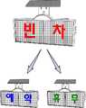
그러나, 도 1 종래 택시용 운행표시기를 설명하기 위한 도면에서와 같이 최근 택시차량의 운행정보를 표시하기 위한 디스플레이가 전광판모듈 또는 디스플레이장치 전체를 LED로 제작함에 따라 상기 디스플레이를 통해 다양한 문자와 배경효과를 표현할 수 있다는 장점은 있지만, 이를 제어하기 위한 마이컴과 복잡한 회로구성이 구비되어야 하고, 고가의 전광판모듈을 사용함에 따라 제품의 단가를 상승시키는 요인이 되는 문제점이 있다.However, as shown in the drawing for explaining a conventional taxi driving indicator, a display for displaying recent driving information of a taxi vehicle is manufactured using LED display board modules or the entire display device, and various characters and background effects through the display. Although there is an advantage that can be expressed, a microcomputer and a complicated circuit configuration for controlling this should be provided, and there is a problem that increases the unit cost of the product according to the use of expensive electronic board module.
또한, 상기 종래 운행정보 표시기를 차량에 고정하기 위해 상기 장치의 일측면에 양면테이프를 사용하여 차량의 룸미러 하부측 앞유리에 접착하여 고정하였지만, 한번 고정된 표시기의 위치 변경 시에는 상기 표시기를 탈착해야만 하기 때문에 양면테이프의 접착성이 떨어져 재부착시 쉽게 상기 표시기가 떨어지게 되는 단 점이 있다.In addition, in order to fix the conventional driving information indicator to the vehicle, a double-sided tape was attached to one side of the device and fixed to the windshield lower side of the vehicle, but the indicator was changed when the position of the indicator once fixed was changed. Since it has to be detached, there is a disadvantage in that the adhesion of the double-sided tape is poor and the indicator easily falls off when reattaching.
뿐만 아니라, 상기 양면테이프는 여름철 무더운 날씨에도 접착성이 현저히 낮아지기 때문에 상기 양면테이프의 빈번한 교환이 요하는 등 세심한 관리가 필요하다는 문제점이 있다.In addition, the double-sided tape has a problem that requires careful management, such as frequent replacement of the double-sided tape because the adhesiveness is significantly lowered even in summer hot weather.
본 고안은 상기와 같은 문제점을 해결하기 위해 창안된 것으로, 택시차량의 운행정보를 표출하기 위한 디스플레이를 LED 문자로 배치하여 시인성을 확보하며, 복잡한 회로구성 갖지 않아 제품의 제조단가를 절감할 수 있는 택시용 엘이디 운행정보 표시장치를 제공함에 있다.The present invention was devised to solve the above problems, the display to display the driving information of the taxi vehicle with LED letters to secure visibility, and does not have a complicated circuit configuration can reduce the manufacturing cost of the product The present invention provides a taxi driving information display device.
또한, 하우징과 결합하여 차량의 앞유리와 용이하게 탈착 및 부착 가능한 거치대를 갖는 택시용 엘이디 운행정보 표시장치를 제공함에 또 다른 목적이 있다.In addition, it is another object to provide an LED driving information display device for a taxi having a cradle that can be easily attached and detached and attached to the windshield of the vehicle.
또한, '빈차', '예약', '휴무' 등 글자에 효과를 연출하여 시안성을 확대하고, 야간 주행에서 요금 정산 시 실내등을 온/오프 하는 불편함을 해소하기 위한 보조조명을 제공하는 택시용 엘이디 운행정보 표시장치를 제공함에 또 다른 목적이 있다.In addition, taxis that provide effects on letters such as 'empty cars', 'reservations' and 'holidays' expand the Xi'an and provide auxiliary lighting to alleviate the inconvenience of turning on / off the interior lights when paying the fare when driving at night. It is another object to provide a dragon LED driving information display device.
상기와 같은 목적을 달성하기 위한 본 고안 택시용 엘이디 운행정보 표시장치는 일면이 투명한 하우징; 전원공급을 위한 전원공급부; 상기 하우징 내측에서 상기 일면을 향하도록 배치되며, 운행정보를 표시하기 위한 문자가 엘이디로 배치된 디스플레이부; 상기 하우징의 타면과 결합하고, 진공흡착방식을 통해 차량의 앞유리에 부착하기 위한 흡착거치대; 택시차량의 요금미터기와 연결되어 상기 요금미터기로부터 인가되는 운행정보신호를 입력받고, 상기 택시차량의 운행정보를 파악하여 상기 디스플레이부를 제어하기 위한 중앙제어부; 상기 하우징의 외부로 노출 되도록 배치하며, 상기 중앙제어부로 '빈차' 또는 '예약' 신호를 전송하기 위한 스위치; 상기 중앙제어부로부터 인가되는 운행정지신호를 입력받아 작동하며, 상기 디스플레이부의 문자를 순차적으로 점멸하기 위한 순차점멸모듈; 및 상기 하우징의 외측으로 배치되고, 상기 중앙제어부로부터 인가되는 운행정지신호를 입력받아 점등되는 발광수단 및 상기 발광수단의 점등을 지연시키기 위한 타이머소자를 갖는 보조조명부;를 포함하는 것이 특징이다.LED driving information display device of the present invention for achieving the above object is a transparent housing on one surface; A power supply unit for power supply; A display unit disposed to face the one surface inside the housing and having letters for displaying driving information arranged as LEDs; An adsorption base coupled to the other surface of the housing and attached to the windshield of the vehicle through a vacuum adsorption method; A central control unit connected to a fare meter of a taxi vehicle and receiving a driving information signal applied from the fare meter and grasping the driving information of the taxi vehicle to control the display unit; A switch disposed to be exposed to the outside of the housing and configured to transmit a 'vacant vehicle' or 'reservation' signal to the central controller; A sequential flashing module for receiving and operating a driving stop signal applied from the central control unit, and sequentially blinking characters of the display unit; And an auxiliary lighting unit disposed outside the housing and having a light emitting means that is turned on by receiving a driving stop signal applied from the central control unit, and a timer element for delaying the lighting of the light emitting means.
또한, 휴무, 예약을 선택하기 위한 선택 키 및 순차점멸 효과 선택기능, 음성안내 맨트종류 선택기능 및 보조조명의 점등 시간 조절기능 및 온/오프 하기 위한 기능 키를 포함하며, 선택된 키에 따라 키 신호를 적외선 신호의 형태로 송출하기 위한 적외선 리모컨; 및 상기 중앙제어부와 연결되어 상기 하우징 외측으로 배치되며, 상기 적외선 리모컨으로부터 송출되는 적외선 신호를 수신하여 상기 중앙제어부로 전송하는 적외선 수신부;을 더 포함하는 것이 특징이다.In addition, it includes a selection key for selecting holiday, reservation, sequential flashing effect selection function, voice guidance man type selection function, and lighting time adjustment function for auxiliary lighting and a function key for on / off. Infrared remote control for transmitting the in the form of an infrared signal; And an infrared receiver which is connected to the central controller and disposed outside the housing, and receives an infrared signal transmitted from the infrared remote controller and transmits the infrared signal to the central controller.
또한, 상기 택시차량의 운행시작신호 및 운행정지신호를 상기 중앙제어부로부터 입력받아 각 신호에 적합한 음성신호를 출력하기 위한 음성안내부;를 더 포함하는 것이 특징이다.The apparatus may further include a voice guide unit for receiving a driving start signal and a driving stop signal of the taxi vehicle from the central control unit and outputting a voice signal suitable for each signal.
본 고안 택시용 엘이디 운행정보 표시장치는 상기한 해결 수단을 통하여 택시차량의 운행정보를 표출하기 위한 디스플레이를 LED 문자로 배치하고, 순차점멸모듈을 구비하여 상기 LED 문자를 순차적으로 점멸하는 등 간단한 회로 구성으로도 기능적인 효과를 제공함으로써, 시인성 및 식별성을 향상시키며 종래 운행표시기와 같이 고가의 전광판, 이를 제어하기 위한 마이컴이 필요치 않아 장치의 제조단가를 절감할 수 있는 효과가 있다.The LED driving information display device for a taxi according to the present invention has a simple circuit such as a display for displaying the driving information of a taxi vehicle through the above-described solutions, with LED letters, and a sequential flashing module to flash the LED letters sequentially. By providing a functional effect in the configuration, it is possible to improve the visibility and discrimination, and to reduce the manufacturing cost of the device, as a conventional electronic display does not require an expensive display board, a microcomputer for controlling it.
또한, 하우징과 결합하는 흡착거치대를 통해 차량의 앞유리와 용이하게 탈부착 및 위치변경이 가능하도록 하며, 음성안내부를 통해 고객의 승차 또는 하차시 간단한 음성안내를 함으로서 운전자에게는 편의와 실용성을 제공함과 택시차량을 이용하는 고객에게는 질 좋은 서비스 제공을 위한 음성 서비스를 제공하여 브랜드 택시나 법인 택시 등에 대한 홍보 및 서비스질의 향상과 같은 효과가 있다.In addition, the adsorption platform coupled with the housing enables easy detachment and change of position with the windshield of the vehicle, and the voice guidance unit provides convenience and practicality to the driver by providing simple voice guidance when riding or getting off. By providing a voice service for providing quality services to customers who use the vehicle, it has the effect of promoting branded taxis or corporate taxis and improving service quality.
이하, 본 고안에 따른 바람직한 실시 예들에 따른 택시용 LED 표시등에 대하여 첨부된 도면을 참조하여 상세하게 설명하지만, 본 고안이 하기의 실시 예들에 제한되는 것은 아니며, 해당 분야에서 통상의 지식을 가진 자라면 본 고안의 기술적 사상을 벗어나지 않는 범위 내에서 본 고안을 다양한 다른 형태로 구현할 수 있을 것이다. 첨부된 도면에 있어서, 각 구성 요소들의 치수는 본 고안의 명확성을 기하기 위하여 실제보다 확대하여 도시한 것이다. 본 고안에 있어서, 하나의 구성 요소가 다른 구성 요소 "상에", "상부에" 또는 "하부"에 형성되는 것으로 언급되는 경우에는 상기 하나의 구성 요소는 상기 다른 구성요소 위에 형성되거나 또는 아래에 위치하는 것을 의미하거나, 또 다른 구성 요소들이 상기 다른 구성 요소 상에 추가적으로 형성될 수 있다. 또한, 각 구성 요소들이 "제1", "제2" 및/또는 "제3"으로 언급되는 것은 한정하기 위한 것이 아니라 단지 각 구성 요소들을 구분하기 위한 것이다. 따라서 "제1", "제2" 및/또는 "제3"은 각 구성 요소에 대하여 각기 선택적으로 또는 교환적으로 사용될 수 있다.Hereinafter, the LED light for a taxi according to the preferred embodiments of the present invention will be described in detail with reference to the accompanying drawings, but the present invention is not limited to the following embodiments, and those skilled in the art. If it is possible to implement the present invention in various other forms without departing from the technical spirit of the present invention. In the accompanying drawings, the dimensions of each component is shown in an enlarged scale than actual for clarity of the present invention. In the present invention, when one component is referred to as being formed on, on, or under another component, the one component is formed on or below the other component. It is meant to be positioned, or further components may be additionally formed on the other components. In addition, it is to be noted that the respective components are referred to as "first", "second", and / or "third", not merely to limit each component. Thus, "first", "second" and / or "third" may be used selectively or interchangeably for each component.
도 2는 본 고안 택시용 엘이디 운행정보 표시장치의 구성도이고, 도 3은 본 고안 택시용 엘이디 운행정보 표시장치를 보인 도면이며, 도 4는 본 고안 택시용 엘이디 운행정보 표시장치와 흡착거치대의 결합을 설명하기 위한 도면이다.Figure 2 is a block diagram of the LED driving information display device of the present invention, Figure 3 is a view showing the LED driving information display device of the present invention, Figure 4 is the LED driving information display device and adsorptive support for the taxi of the present invention It is a figure for demonstrating coupling | bonding.
또한, 도 5는 본 고안 택시용 엘이디 운행정보 표시장치와 결합한 흡착거치대를 보인 도면이고, 도 6은 본 고안 택시용 엘이디 운행정보 표시장치의 음성안내 및 적외선을 이용한 조작을 설명하기 위한 도면이며, 도 7은 본 고안 택시용 엘이디 운행정보 표시장치에 따른 순차점멸모듈에 의해 동작되는 디스플레이부의 일 예를 설명하기 위한 도면이다.In addition, Figure 5 is a view showing the adsorption cradle coupled with the LED driving information display device for the present invention, Figure 6 is a view for explaining the operation using the voice guidance and infrared of the LED driving information display device for the present invention, 7 is a view for explaining an example of the display unit operated by the sequential flashing module according to the LED driving information display device for the present invention.
본 고안은 택시차량의 요금미터기로부터 운행정보를 입력받아 상기 택시차량의 운행정보를 고객이 식별 가능하도록 하기 위한 택시차량용 운행표시장치에 관한 것이다. 이때, 상기 운행정보를 표시하는 문자가 LED(300)로 구성하여 전력소모를 최소화하고, 종래 운행표시장치보다 시인성을 더욱 확보한 것이 특징이다.The present invention relates to a driving display device for a taxi vehicle for receiving a driving information from the fare meter of the taxi vehicle to enable the customer to identify the driving information of the taxi vehicle. At this time, the character indicating the driving information is composed of
본 고안에 따른 운행정보 표시장치는 하우징(10)과 전원공급을 위한 전원공급부(40) 및 상기 하우징(10)에 배치되어 운행정보를 표시하기 위한 디스플레이부(30)가 구비된다.The driving information display apparatus according to the present invention includes a
또한, 택시차량의 요금미터기와 연결되어 상기 요금미터기로부터 인가되는 운행정보신호를 입력받고, 상기 택시차량의 운행정보를 파악하여 상기 디스플레이부(30)를 제어하기 위한 중앙제어부(20)와 상기 디스플레이부(30)의 효과기능을 제 공하는 순차점멸모듈(60) 및 고객의 요금정산 시 일정시간 동안 조명을 제공하는 보조조명부(70)를 포함한다.In addition, the
그리고, 본 고안에 따른 운행정보 표시장치를 차량의 앞유리에 부착하여 거치하기 위한 흡착거치대(50) 더 포함한다.In addition, the driving information display device according to the present invention further comprises a
상기한 본 고안에 따른 운행정보 표시장치의 구성을 도 2를 참조하여 구체적으로 설명하자면, 상기 하우징(10)은 직육면체 형상으로 일면을 투명하게 형성하여 상기 디스플레이부(30)가 배치되어 운행정보를 식별하도록 한다. 또한, 상기 전원공급부(40)는 본 고안에 따른 운행정보 표시장치의 전원공급을 위한 것으로 차량으로부터 DC전원을 입력받아 상기 디스플레이부(30)나 중앙제어부(20)로 공급하게 된다.The configuration of the driving information display device according to the present invention will be described in detail with reference to FIG. 2. The
상기 디스플레이부(30)는 도 3에서 도시한 바와 같이 기판 형태로 상기 하우징(10) 내측에서 상기 하우징(10)의 투명한 일면을 향하도록 배치되어 운행정보를 표시하게 된다. 이때, 상기 디스플레이부(30)는 운행정보를 표시하기 위해 '빈차' '예약' 및 '휴무'과 같은 문자를 기판상에 형성하되 상기 문자는 LED(300)로 이루어진 것이 특징이다.As shown in FIG. 3, the
또한, 상기 문자를 다양한 색상의 LED로 조합하여 배치함에 따라 다양한 색상의 문자로 표현함으로써 시인성을 극대화하는 것이 바람직하다.In addition, it is desirable to maximize the visibility by expressing the letters in a variety of colors as the letters are arranged in combination with a variety of LEDs.
즉, 종래 운행정보표시기의 디스플레이가 전광판 방식이거나 또는 전체를 LED로 구성함으로써 문자를 표현하기 위한 고가의 마이컴 및 복잡한 회로 구성이 필요한 것과 비교하면, 본 고안은 운행정보를 표시하기 위한 문자만을 LED(300)로 구성하여 시인성은 종래 운행정보표시기와 동일하면서도 복잡한 회로구성이 필요하지 않아 제품의 제조단가를 절감할 수 있는 특징이 있다.In other words, the display of the conventional driving information display is a display board type or the entire structure of the LED, compared to the need for expensive microcomputer and complicated circuit configuration for expressing the character, the present invention is only LED for displaying the driving information ( Visibility is the same as the conventional navigation information display, but does not require a complicated circuit configuration, there is a feature that can reduce the manufacturing cost of the product.
한편, 상기 중앙제어부(20)는 택시차량의 요금미터기와 케이블을 통해 연결되어, 상기 요금미터기로부터 택시차량의 운행정보신호를 입력받게 된다. 여기에서 운행정보신호라 함은 차량의 현재 운행상태에 따른 정보 신호를 말하며 상기 택시차량의 운전자가 요금미터기를 조작함으로써 신호가 송출된다. 여기에서, 상기 요금미터기로부터 중앙제어부(20)로 송출되는 운행정보신호는 고객이 승차하여 요금미터기가 작동하게 되면 운행시작신호를, 고객이 하차하여 상기 요금미터기가 작동하지 않은 상태에서는 운행정지신호를 송출한다.On the other hand, the
이때, 상기 중앙제어부(20)로부터 운행정보신호를 입력받은 상기 디스플레이부(30)는 해당 운행정보에 적합한 LED(300) 문자를 점등시키게 된다. 즉 상기한 운행정지신호가 입력되면 상기 디스플레이부(30)는 '빈차' LED 문자를 점등하게 된다.In this case, the
또한, 고객이 택시차량에 탑승하여 요금미터기가 작동하게 되면, 운행시작신호가 입력되어 상기 '빈차' LED 문자는 멸등하게 된다.In addition, when the customer boards a taxi vehicle and the fare meter is operated, a driving start signal is input and the 'empty car' LED character is flickered.
이외에도 상기 요금미터기는 택시차량의 예약 설정할 수 있으며 그에 따른 운행정보신호가 송출하게 된다.In addition, the fare meter can set the reservation of the taxi vehicle and the operation information signal is transmitted accordingly.
여기에서 본 고안에 따른 운행정보 표시장치는 상기 하우징(10)의 일측으로 돌출되도록 배치된 스위치(100)를 구비하고, 상기 스위치(100)를 통해 운전자가 상기 디스플레이부(30)에서 표출되는 LED(300) 문자를 표출가능하게 해야 바람직하 다.The driving information display apparatus according to the present invention includes a
즉, 상기 디스플레이부(30)는 상기 중앙제어부(20)로부터 인가되는 신호에 따라 LED(300) 문자를 표출하기도 하지만, 상기 운전자가 상기 하우징(10)에 배치되는 스위치를 통해서 임의로 '빈차' '예약' 과 같은 LED 문자를 표출하기도 한다.That is, the
상기 스위치(100)는 상기 중앙제어부(20)와 연결되어 스위치(100)조작에 따른 '빈차' 또는 '예약' 신호를 상기 중앙제어부(20)가 입력받고, 해당 신호에 따른 문자를 상기 디스플레이부(30)가 표출하게 된다.The
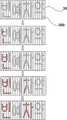
한편, 상기 순차점멸모듈(60)은 상기 중앙제어부(20)로부터 인가되는 운행정지신호를 입력받아 작동하게 되며, 상기 운행정보를 표출하기 위한 디스플레이부(30)의 LED(300) 문자를 순차적으로 점멸한다. 다시 말해 택시차량의 운행정지신호를 중앙제어부(20)가 송출하게 되면, 이를 상기 순차점멸모듈(60)이 입력받고 상기 디스플레이부(30)에 형성된 LED(300) 문자를 우측방향 또는 좌측방향을 따라 순차적으로 점멸시키게 된다.On the other hand, the
도 7을 일 예로 설명하자면, 상기 순차점멸모듈(60)은 상기 LED(300) 문자의 최우측의 문자인 '빈' 을 순차적으로 점등시킨 뒤 '차'를 순차적으로 점등시킨다. 그 뒤, 동일한 방법으로 '빈' 및 '차'를 순차적으로 멸등시키게 된다.Referring to FIG. 7 as an example, the
또한, 상기 순차점멸모듈(60)은 다른 색상의 LED의 조합으로 여러 색상의 문자를 표현하거나 색상의 변화(디밍효과), 문자별 시간차 점멸, 전체 문자 점멸, 자멸 색상 변화 등의 다양한 문자 변화 등의 효과를 제공하여 시인성을 극대화할 수 있다.In addition, the
이와 같이, 표출하고자 하는 운행정보 문자를 순차적으로 점멸하도록 하기 위해서는 상기 LED(300)로 구성된 각 문자는 각기 상이한 색상을 갖고, 독립적으로 전원을 공급받도록 회로가 구성되어 있어야 한다.As such, in order to sequentially display the driving information characters to be displayed, each character composed of the
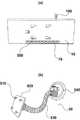
도 4 내지 도 5는 본 고안에 따른 흡착거치대(50)를 설명하기 위한 것으로, 도면을 참조하면 상기 흡착거치대(50)는 상기 하우징(10)의 타면과 결합하여 택시차량의 앞유리에 부착하기 위한 것으로, 통상의 PDA, 휴대폰 또는 네비게이션을 차량에 거치하기 위한 진공흡착방식의 거치대를 적용한다.4 to 5 are for explaining the
좀 더 구체적으로는 도 4(b)에 도시한 바와 같이 상기 흡착거치대(30)는 진공에 의해 부착력을 제공하는 흡착판(540)과 상기 하우징(10)과 결합하기 위해 다수의 결합핀(510)이 형성된 고정판(520) 및 상기 흡착판(540)과 고정판(520)을 연결하며 위치조절이 가능하게 하는 후렉시블바(530)로 구성된다.More specifically, as shown in FIG. 4 (b), the
또한, 도 4(a)에서와 같이 상기 하우징(10)의 타면은 상기 고정판(520)에 형성된 다수의 결합핀(510)과 결합하기 위해 상기 결합핀(510)과 대응하는 결합홈(500)을 형성하는 것이 바람직하다. 이때, 상기한 결합방식에 한정되는 것이 아니라 다양한 결합수단을 통하여 상기 흡착거치대(50)와 하우징(10)이 결합할 수 있다.In addition, the other surface of the
따라서, 상기 흡착거치대(50)에 따라 종래 표시장치가 차량의 앞유리에 부착하기 위하여 양면테이프를 이용함으로써 발생하였던 문제점을 보완할 수 있으며, 운전자에 의해 용이하게 위치이동이 가능하게 된다.Therefore, the problem caused by using the double-sided tape to attach the display device to the windshield of the vehicle according to the
한편, 상기 보조조명부(70)는 도 4(a)에 도시한 바와 같이 상기 하우징(10) 의 외측으로 발광수단을 배치하고, 상기 중앙제어부(20)로부터 송출되는 운행정지신호 입력에 따라 점등되기 때문에 어두운 야간에 요금정산 시 택시차량의 운전자 내지 고객에게 보조조명을 제공하게 된다.On the other hand, the
여기에서, 상기 발광수단의 배치는 상기 하우징(10)의 하단에서 택시 차량의 실내 바닥을 향해 조사되도록 배치해야되며, 상기 발광수단 역시 전력소모가 적고 시인성이 우수한 LED를 사용하는 것이 바람직하다.Here, the arrangement of the light emitting means should be arranged so as to be irradiated toward the interior floor of the taxi vehicle from the bottom of the
이때, 상기 보조조명부(70)는 상기 중앙제어부로부터 인가되는 운행정지신호를 입력받아 점등되는 상기 발광수단의 점등시간을 일정 시간 동안만 유지하기 위한 타이머소자를 더 포함하여 상기 발광수단이 운행정지신호에 따라 일정시간 동안만 점등 되도록 한다.At this time, the
상기 타이머소자는 고객에 대한 요금 정산시간을 감안하여 상기 발광수단의 점등 유지시간을 20초 내지 30초로 셋팅하는 것이 가장 바람직하다.The timer device is most preferably set to 20 seconds to 30 seconds the lighting holding time of the light emitting means in consideration of the charge settlement time for the customer.
한편, 본 고안에 따른 운행정보 표시장치는 기본적으로 스위치(100)를 이용하여 디스플레이부(30)에서 문자를 표출하기도 하지만, 상기 도 1 또는 도 6에 도시한 바와 같이 적외선 수신부(85)와 적외선 리모컨(80)을 더 포함하여 택시차량의 운전자에게 편의 사항을 추가로 제공하게 되며, 그 외에도 음성안내부(90)를 더 포함하게 된다. 상기 도 6을 참조하여 설명하자면, 상기 적외선수신부(85)는 상기 하우징(10) 외측으로 배치되어 상기 적외선 리모콘(80)으로부터 전송되는 적외선 무선신호를 디지털 신호로 변환하여 상기 중앙제어부(20)로 전송한다. 상기 적외선 리모컨(80)은 다수의 키 버튼이 구비되며, 각 키 버튼을 선택함에 따라 각기 상이 한 적외선 신호가 송출된다.On the other hand, the driving information display apparatus according to the present invention basically expresses a character in the
여기에서, 상기 다수의 키 버튼은 휴무, 예약을 선택하기 위한 선택 키 및 순차점멸 효과 선택기능, 음성안내 맨트종류 선택 기능, 보조조명의 점등 시간 조절 기능 및 온/오프 동작을 위한 기능 키를 포함한다.Here, the plurality of key buttons include a selection key for selecting holiday, reservation and a sequential blinking effect selection function, a voice guidance man type selection function, a lighting time adjustment function for an auxiliary light, and a function key for on / off operation. do.
다시 말해, 상기 적외선 리모컨(80)의 선택된 키에 따라 해당 키의 특정 신호가 적외선 신호 형태로 송출하며, 상기 적외선 수신부(85)는 상기 중앙제어부(20)와 연결되어 상기 적외선 리모컨(80)으로부터 송출되는 적외선 신호를 아날로그 신호를 수신하여 상기 중앙제어부(20)로 전송하게 된다.In other words, a specific signal of the corresponding key is transmitted in the form of an infrared signal according to the selected key of the infrared
상기 중앙제어부(20)는 상기 적외선 수신부(85)으로부터 입력된 신호에 따라 디스플레이부(30)의 운행정보 LED(300) 문자를 발광시거나 각 기능에 따른 동작을 하게 한다.The
이때, 운전자는 적외선 리모컨(80)의 선택 키를 통해 예약, 휴무 등의 운행정보를 입력할 수도 있지만, 상기 중앙제어부(30)와 연결되며, 상기 하우징(10)의 소정부위에 배치된 스위치(100)를 통하여 상기 예약, 휴무 신호를 입력할 수도 있다.In this case, the driver may input driving information such as reservation or absence through the selection key of the infrared
한편, 상기 음성안내부(90)는 상기 택시차량의 운행시작신호 및 운행정지신호를 상기 중앙제어부(20)로부터 입력받아 각 신호에 적합한 음성신호를 출력하여 상기 하우징(10) 외측으로 배치되는 스피커(900)를 통하여 고객에게 음성안내를 하게 된다.Meanwhile, the
여기에서, 상기 음성안내부(90)는 미리 녹음된 음성신호를 저장하기 위한 메 모리를 포함하는 것이 바람직하다.Here, the
일 예로, 상기 고객이 택시차량에 승차하게 되면 운전자는 요금미터기를 조작하여 중앙제어부(20)로 운행시작신호를 송출하게 되고, 상기 중앙제어부(20)로부터 운행시작신호를 입력받은 상기 음성안내부(90)의 메모리에 녹음된 음성신호를 출력한다. 마찬가지로 고객의 하차시 상기 운전자가 요금정산을 위해 요금미터기를 조작하면 운행정지신호가 송출하게 되고, 이에 따라 상기 중앙제어부(20)로부터 운행정지신호를 입력받은 상기 음성안내부(90)는 그에 적합한 음성신호를 출력하게 되고, 상기한 적외선 리모컨(80)을 통해서도 음성신호의 선택이 가능하게 된다.For example, when the customer rides a taxi vehicle, the driver operates a fare meter to transmit a driving start signal to the
이때, 상기 메모리에 저장된 음성신호는 각 신호에 적합하도록 운행시작신호 시에는 '안녕하세요', '어서오세요', '안녕하세요 00 운수 00입니다' 등이 될 수 있으며, 운행정지신호 시에는 '안녕히 가세요', '감사합니다', '저희 00 운수를 이용해 주셔서 감사합니다' 등이 될 수 있다.At this time, the voice signal stored in the memory may be 'Hello', 'Welcome', 'Hello 00 luck 00', etc. when the start signal is appropriate to each signal, and 'Goodbye' when the stop signal , "Thank you," "Thank you for using our 00 transportation."
따라서, 상기한 적외선 수신부(85) 및 적외선 리모컨(80)에 따라 운전자의 편의성을 제공하는 한편, 상기 음성안내부(90)를 통해 택시차량의 이용하는 고객에게 음성 서비스를 제공하여 브랜드의 홍보 및 서비스 질을 향상시키는 효과가 발생한다.Therefore, while providing the convenience of the driver according to the
이상에서는 본 고안을 특정의 바람직한 실시 예를 들어 도시하고 설명하였으나, 본 고안은 상기한 실시 예에 한정되지 아니하며, 본 고안의 정신을 벗어나지 않는 범위 내에서 당해 고안이 속하는 기술분야에서 통상의 지식을 가진자에 의해 다양한 변경과 수정이 가능할 것이다.Although the present invention has been shown and described with reference to certain preferred embodiments, the present invention is not limited to the above-described embodiments, and the general knowledge in the technical field to which the present invention belongs without departing from the spirit of the present invention. Various changes and modifications may be made by the possessor.
도 1은 종래 택시용 운행표시기를 설명하기 위한 도면.1 is a view for explaining a driving indicator for a conventional taxi.
도 2는 본 고안 택시용 엘이디 운행정보 표시장치의 구성도.Figure 2 is a block diagram of the LED driving information display device for a taxi according to the present invention.
도 3은 본 고안 택시용 엘이디 운행정보 표시장치를 보인 도면.3 is a view showing the LED driving information display device for the subject innovation taxi.
도 4는 본 고안 택시용 엘이디 운행정보 표시장치와 흡착거치대의 결합을 설명하기 위한 도면.Figure 4 is a view for explaining the combination of the LED driving information display device and the suction cradle for the subject innovation.
도 5는 본 고안 택시용 엘이디 운행정보 표시장치와 결합한 흡착거치대를 보인 도면.5 is a view showing a suction cradle coupled with the LED driving information display device for a taxi according to the present invention.
도 6은 본 고안 택시용 엘이디 운행정보 표시장치의 음성안내 및 적외선을 이용한 조작을 설명하기 위한 도면.Figure 6 is a view for explaining the operation using the voice guidance and infrared ray of the LED driving information display device of the subject innovation.
도 7은 본 고안 택시용 엘이디 운행정보 표시장치에 따른 순차점멸모듈에 의해 동작되는 디스플레이부의 일 예를 설명하기 위한 도면.7 is a view for explaining an example of a display unit operated by a sequential flashing module according to the LED driving information display device for a taxi according to the present invention.
*** 도면의 주요부분에 대한 도면부호의 간단한 설명 ****** Brief description of the reference numerals for the main parts of the drawings ***
10: 하우징 20 : 중앙제어부10: housing 20: central control unit
30 : 디스플레이부 40 : 전원공급부30: display unit 40: power supply unit
50 : 흡착거치대 60 : 순차점멸모듈50: adsorption base 60: sequential flashing module
70 : 보조조명부 80 : 적외선리모컨70: auxiliary lighting unit 80: infrared remote control
85 : 적외선수신부 90 : 음성안내부85: infrared receiver 90: voice guidance
100 : 스위치 300 : LED100: switch 300: LED
500 : 결합홈 510 : 결합핀500: coupling groove 510: coupling pin
520 : 고정판 530 : 후렉시블바520: fixing plate 530: flexible bar
540 : 흡착판 900 : 스피커540: adsorption plate 900: speaker
Claims (3)
Translated fromKoreanPriority Applications (1)
| Application Number | Priority Date | Filing Date | Title |
|---|---|---|---|
| KR2020070014650UKR200440677Y1 (en) | 2007-09-03 | 2007-09-03 | Taxi LED Driving Information Display |
Applications Claiming Priority (1)
| Application Number | Priority Date | Filing Date | Title |
|---|---|---|---|
| KR2020070014650UKR200440677Y1 (en) | 2007-09-03 | 2007-09-03 | Taxi LED Driving Information Display |
Publications (1)
| Publication Number | Publication Date |
|---|---|
| KR200440677Y1true KR200440677Y1 (en) | 2008-06-25 |
Family
ID=43658104
Family Applications (1)
| Application Number | Title | Priority Date | Filing Date |
|---|---|---|---|
| KR2020070014650UExpired - Fee RelatedKR200440677Y1 (en) | 2007-09-03 | 2007-09-03 | Taxi LED Driving Information Display |
Country Status (1)
| Country | Link |
|---|---|
| KR (1) | KR200440677Y1 (en) |
Cited By (2)
| Publication number | Priority date | Publication date | Assignee | Title |
|---|---|---|---|---|
| KR101308531B1 (en)* | 2013-03-07 | 2013-09-17 | 주식회사 아이온뱅크 | A hire-signal lamp of taxi for preventing illegal refusal to passengers and the prevention method using the same |
| KR20230112299A (en)* | 2022-01-20 | 2023-07-27 | 심휘경 | Projection device for the vehicle glass using unit solid state surface light source and meta-mirror |
- 2007
- 2007-09-03KRKR2020070014650Upatent/KR200440677Y1/ennot_activeExpired - Fee Related
Cited By (3)
| Publication number | Priority date | Publication date | Assignee | Title |
|---|---|---|---|---|
| KR101308531B1 (en)* | 2013-03-07 | 2013-09-17 | 주식회사 아이온뱅크 | A hire-signal lamp of taxi for preventing illegal refusal to passengers and the prevention method using the same |
| KR20230112299A (en)* | 2022-01-20 | 2023-07-27 | 심휘경 | Projection device for the vehicle glass using unit solid state surface light source and meta-mirror |
| KR102614293B1 (en)* | 2022-01-20 | 2023-12-14 | 심휘경 | Projection device for the vehicle glass using unit solid state surface light source and meta-mirror |
Similar Documents
| Publication | Publication Date | Title |
|---|---|---|
| US5124845A (en) | Interior rearvision mirror | |
| US20030142044A1 (en) | License plate frame with programmable electronic display | |
| US7121700B1 (en) | Vehicle advertising sign illumination apparatus | |
| US20140130387A1 (en) | Backlit Graphic Display Device with Device-to-Surface Mounts | |
| US20110013109A1 (en) | Solar Power Message Display For Windows | |
| US11028995B2 (en) | Glazing with detachable light device | |
| KR200440677Y1 (en) | Taxi LED Driving Information Display | |
| JP2009508181A (en) | Equipment for signaling the wait staff | |
| KR100957522B1 (en) | Car driver's contact indicator | |
| US20050243567A1 (en) | Illumination device | |
| RU58249U1 (en) | INFORMATION ELECTRICAL DISPLAY | |
| JP2675849B2 (en) | Interior rearview mirror | |
| WO2011055263A1 (en) | Poster holder and method for controlling a poster holder | |
| JP3134911U (en) | Display device for car sales price etc. | |
| CN221825365U (en) | Warning light and car | |
| JP3068425U (en) | Taxi rooftop indicator | |
| CN220174890U (en) | Wine bottle bracket | |
| CN216813988U (en) | Lighting device and lighting system | |
| CN211739013U (en) | A car interior atmosphere light controller | |
| KR20120009118A (en) | Car Transparent Display Board | |
| KR101319854B1 (en) | Apparatus displaying contact number | |
| KR200286516Y1 (en) | Device for displaying empty taxi sign | |
| KR200341432Y1 (en) | A Route Indicator for Motorcars for Business Use | |
| KR200385401Y1 (en) | Notice apparatus of taxi information | |
| JPH1049076A (en) | Bus destination display device |
Legal Events
| Date | Code | Title | Description |
|---|---|---|---|
| A201 | Request for examination | ||
| UA0108 | Application for utility model registration | St.27 status event code:A-0-1-A10-A12-nap-UA0108 | |
| UA0201 | Request for examination | St.27 status event code:A-1-2-D10-D11-exm-UA0201 | |
| E701 | Decision to grant or registration of patent right | ||
| UE0701 | Decision of registration | St.27 status event code:A-1-2-D10-D22-exm-UE0701 | |
| REGI | Registration of establishment | ||
| UR0701 | Registration of establishment | St.27 status event code:A-2-4-F10-F11-exm-UR0701 | |
| UR1002 | Payment of registration fee | St.27 status event code:A-2-2-U10-U11-oth-UR1002 Fee payment year number:1 | |
| UG1601 | Publication of registration | St.27 status event code:A-4-4-Q10-Q13-nap-UG1601 | |
| LAPS | Lapse due to unpaid annual fee | ||
| UC1903 | Unpaid annual fee | St.27 status event code:A-4-4-U10-U13-oth-UC1903 Not in force date:20110620 Payment event data comment text:Termination Category : DEFAULT_OF_REGISTRATION_FEE | |
| UC1903 | Unpaid annual fee | St.27 status event code:N-4-6-H10-H13-oth-UC1903 Ip right cessation event data comment text:Termination Category : DEFAULT_OF_REGISTRATION_FEE Not in force date:20110620 | |
| P22-X000 | Classification modified | St.27 status event code:A-4-4-P10-P22-nap-X000 | |
| P22-X000 | Classification modified | St.27 status event code:A-4-4-P10-P22-nap-X000 | |
| P22-X000 | Classification modified | St.27 status event code:A-4-4-P10-P22-nap-X000 |