KR102834461B1 - Integrated showerhead with improved hole pattern to deliver radical and precursor gases to downstream chamber to enable remote plasma film deposition - Google Patents
Integrated showerhead with improved hole pattern to deliver radical and precursor gases to downstream chamber to enable remote plasma film depositionDownload PDFInfo
- Publication number
- KR102834461B1 KR102834461B1KR1020207019670AKR20207019670AKR102834461B1KR 102834461 B1KR102834461 B1KR 102834461B1KR 1020207019670 AKR1020207019670 AKR 1020207019670AKR 20207019670 AKR20207019670 AKR 20207019670AKR 102834461 B1KR102834461 B1KR 102834461B1
- Authority
- KR
- South Korea
- Prior art keywords
- holes
- showerhead
- groups
- injectors
- paragraph
- Prior art date
- Legal status (The legal status is an assumption and is not a legal conclusion. Google has not performed a legal analysis and makes no representation as to the accuracy of the status listed.)
- Active
Links
Images


Classifications
- C—CHEMISTRY; METALLURGY
- C23—COATING METALLIC MATERIAL; COATING MATERIAL WITH METALLIC MATERIAL; CHEMICAL SURFACE TREATMENT; DIFFUSION TREATMENT OF METALLIC MATERIAL; COATING BY VACUUM EVAPORATION, BY SPUTTERING, BY ION IMPLANTATION OR BY CHEMICAL VAPOUR DEPOSITION, IN GENERAL; INHIBITING CORROSION OF METALLIC MATERIAL OR INCRUSTATION IN GENERAL
- C23C—COATING METALLIC MATERIAL; COATING MATERIAL WITH METALLIC MATERIAL; SURFACE TREATMENT OF METALLIC MATERIAL BY DIFFUSION INTO THE SURFACE, BY CHEMICAL CONVERSION OR SUBSTITUTION; COATING BY VACUUM EVAPORATION, BY SPUTTERING, BY ION IMPLANTATION OR BY CHEMICAL VAPOUR DEPOSITION, IN GENERAL
- C23C16/00—Chemical coating by decomposition of gaseous compounds, without leaving reaction products of surface material in the coating, i.e. chemical vapour deposition [CVD] processes
- C23C16/44—Chemical coating by decomposition of gaseous compounds, without leaving reaction products of surface material in the coating, i.e. chemical vapour deposition [CVD] processes characterised by the method of coating
- C23C16/455—Chemical coating by decomposition of gaseous compounds, without leaving reaction products of surface material in the coating, i.e. chemical vapour deposition [CVD] processes characterised by the method of coating characterised by the method used for introducing gases into reaction chamber or for modifying gas flows in reaction chamber
- C23C16/45563—Gas nozzles
- C23C16/45565—Shower nozzles
- C—CHEMISTRY; METALLURGY
- C23—COATING METALLIC MATERIAL; COATING MATERIAL WITH METALLIC MATERIAL; CHEMICAL SURFACE TREATMENT; DIFFUSION TREATMENT OF METALLIC MATERIAL; COATING BY VACUUM EVAPORATION, BY SPUTTERING, BY ION IMPLANTATION OR BY CHEMICAL VAPOUR DEPOSITION, IN GENERAL; INHIBITING CORROSION OF METALLIC MATERIAL OR INCRUSTATION IN GENERAL
- C23C—COATING METALLIC MATERIAL; COATING MATERIAL WITH METALLIC MATERIAL; SURFACE TREATMENT OF METALLIC MATERIAL BY DIFFUSION INTO THE SURFACE, BY CHEMICAL CONVERSION OR SUBSTITUTION; COATING BY VACUUM EVAPORATION, BY SPUTTERING, BY ION IMPLANTATION OR BY CHEMICAL VAPOUR DEPOSITION, IN GENERAL
- C23C16/00—Chemical coating by decomposition of gaseous compounds, without leaving reaction products of surface material in the coating, i.e. chemical vapour deposition [CVD] processes
- C23C16/44—Chemical coating by decomposition of gaseous compounds, without leaving reaction products of surface material in the coating, i.e. chemical vapour deposition [CVD] processes characterised by the method of coating
- C23C16/455—Chemical coating by decomposition of gaseous compounds, without leaving reaction products of surface material in the coating, i.e. chemical vapour deposition [CVD] processes characterised by the method of coating characterised by the method used for introducing gases into reaction chamber or for modifying gas flows in reaction chamber
- C23C16/45523—Pulsed gas flow or change of composition over time
- C23C16/45525—Atomic layer deposition [ALD]
- C23C16/45527—Atomic layer deposition [ALD] characterized by the ALD cycle, e.g. different flows or temperatures during half-reactions, unusual pulsing sequence, use of precursor mixtures or auxiliary reactants or activations
- C23C16/45536—Use of plasma, radiation or electromagnetic fields
- C—CHEMISTRY; METALLURGY
- C23—COATING METALLIC MATERIAL; COATING MATERIAL WITH METALLIC MATERIAL; CHEMICAL SURFACE TREATMENT; DIFFUSION TREATMENT OF METALLIC MATERIAL; COATING BY VACUUM EVAPORATION, BY SPUTTERING, BY ION IMPLANTATION OR BY CHEMICAL VAPOUR DEPOSITION, IN GENERAL; INHIBITING CORROSION OF METALLIC MATERIAL OR INCRUSTATION IN GENERAL
- C23C—COATING METALLIC MATERIAL; COATING MATERIAL WITH METALLIC MATERIAL; SURFACE TREATMENT OF METALLIC MATERIAL BY DIFFUSION INTO THE SURFACE, BY CHEMICAL CONVERSION OR SUBSTITUTION; COATING BY VACUUM EVAPORATION, BY SPUTTERING, BY ION IMPLANTATION OR BY CHEMICAL VAPOUR DEPOSITION, IN GENERAL
- C23C16/00—Chemical coating by decomposition of gaseous compounds, without leaving reaction products of surface material in the coating, i.e. chemical vapour deposition [CVD] processes
- C23C16/44—Chemical coating by decomposition of gaseous compounds, without leaving reaction products of surface material in the coating, i.e. chemical vapour deposition [CVD] processes characterised by the method of coating
- C23C16/455—Chemical coating by decomposition of gaseous compounds, without leaving reaction products of surface material in the coating, i.e. chemical vapour deposition [CVD] processes characterised by the method of coating characterised by the method used for introducing gases into reaction chamber or for modifying gas flows in reaction chamber
- C23C16/45563—Gas nozzles
- C23C16/4557—Heated nozzles
- C—CHEMISTRY; METALLURGY
- C23—COATING METALLIC MATERIAL; COATING MATERIAL WITH METALLIC MATERIAL; CHEMICAL SURFACE TREATMENT; DIFFUSION TREATMENT OF METALLIC MATERIAL; COATING BY VACUUM EVAPORATION, BY SPUTTERING, BY ION IMPLANTATION OR BY CHEMICAL VAPOUR DEPOSITION, IN GENERAL; INHIBITING CORROSION OF METALLIC MATERIAL OR INCRUSTATION IN GENERAL
- C23C—COATING METALLIC MATERIAL; COATING MATERIAL WITH METALLIC MATERIAL; SURFACE TREATMENT OF METALLIC MATERIAL BY DIFFUSION INTO THE SURFACE, BY CHEMICAL CONVERSION OR SUBSTITUTION; COATING BY VACUUM EVAPORATION, BY SPUTTERING, BY ION IMPLANTATION OR BY CHEMICAL VAPOUR DEPOSITION, IN GENERAL
- C23C16/00—Chemical coating by decomposition of gaseous compounds, without leaving reaction products of surface material in the coating, i.e. chemical vapour deposition [CVD] processes
- C23C16/44—Chemical coating by decomposition of gaseous compounds, without leaving reaction products of surface material in the coating, i.e. chemical vapour deposition [CVD] processes characterised by the method of coating
- C23C16/46—Chemical coating by decomposition of gaseous compounds, without leaving reaction products of surface material in the coating, i.e. chemical vapour deposition [CVD] processes characterised by the method of coating characterised by the method used for heating the substrate
- C—CHEMISTRY; METALLURGY
- C23—COATING METALLIC MATERIAL; COATING MATERIAL WITH METALLIC MATERIAL; CHEMICAL SURFACE TREATMENT; DIFFUSION TREATMENT OF METALLIC MATERIAL; COATING BY VACUUM EVAPORATION, BY SPUTTERING, BY ION IMPLANTATION OR BY CHEMICAL VAPOUR DEPOSITION, IN GENERAL; INHIBITING CORROSION OF METALLIC MATERIAL OR INCRUSTATION IN GENERAL
- C23C—COATING METALLIC MATERIAL; COATING MATERIAL WITH METALLIC MATERIAL; SURFACE TREATMENT OF METALLIC MATERIAL BY DIFFUSION INTO THE SURFACE, BY CHEMICAL CONVERSION OR SUBSTITUTION; COATING BY VACUUM EVAPORATION, BY SPUTTERING, BY ION IMPLANTATION OR BY CHEMICAL VAPOUR DEPOSITION, IN GENERAL
- C23C16/00—Chemical coating by decomposition of gaseous compounds, without leaving reaction products of surface material in the coating, i.e. chemical vapour deposition [CVD] processes
- C23C16/44—Chemical coating by decomposition of gaseous compounds, without leaving reaction products of surface material in the coating, i.e. chemical vapour deposition [CVD] processes characterised by the method of coating
- C23C16/50—Chemical coating by decomposition of gaseous compounds, without leaving reaction products of surface material in the coating, i.e. chemical vapour deposition [CVD] processes characterised by the method of coating using electric discharges
- C23C16/505—Chemical coating by decomposition of gaseous compounds, without leaving reaction products of surface material in the coating, i.e. chemical vapour deposition [CVD] processes characterised by the method of coating using electric discharges using radio frequency discharges
- C—CHEMISTRY; METALLURGY
- C23—COATING METALLIC MATERIAL; COATING MATERIAL WITH METALLIC MATERIAL; CHEMICAL SURFACE TREATMENT; DIFFUSION TREATMENT OF METALLIC MATERIAL; COATING BY VACUUM EVAPORATION, BY SPUTTERING, BY ION IMPLANTATION OR BY CHEMICAL VAPOUR DEPOSITION, IN GENERAL; INHIBITING CORROSION OF METALLIC MATERIAL OR INCRUSTATION IN GENERAL
- C23C—COATING METALLIC MATERIAL; COATING MATERIAL WITH METALLIC MATERIAL; SURFACE TREATMENT OF METALLIC MATERIAL BY DIFFUSION INTO THE SURFACE, BY CHEMICAL CONVERSION OR SUBSTITUTION; COATING BY VACUUM EVAPORATION, BY SPUTTERING, BY ION IMPLANTATION OR BY CHEMICAL VAPOUR DEPOSITION, IN GENERAL
- C23C16/00—Chemical coating by decomposition of gaseous compounds, without leaving reaction products of surface material in the coating, i.e. chemical vapour deposition [CVD] processes
- C23C16/44—Chemical coating by decomposition of gaseous compounds, without leaving reaction products of surface material in the coating, i.e. chemical vapour deposition [CVD] processes characterised by the method of coating
- C23C16/52—Controlling or regulating the coating process
- H—ELECTRICITY
- H01—ELECTRIC ELEMENTS
- H01J—ELECTRIC DISCHARGE TUBES OR DISCHARGE LAMPS
- H01J37/00—Discharge tubes with provision for introducing objects or material to be exposed to the discharge, e.g. for the purpose of examination or processing thereof
- H01J37/32—Gas-filled discharge tubes
- H01J37/32431—Constructional details of the reactor
- H01J37/32733—Means for moving the material to be treated
- H01J37/32743—Means for moving the material to be treated for introducing the material into processing chamber
- H—ELECTRICITY
- H01—ELECTRIC ELEMENTS
- H01L—SEMICONDUCTOR DEVICES NOT COVERED BY CLASS H10
- H01L21/00—Processes or apparatus adapted for the manufacture or treatment of semiconductor or solid state devices or of parts thereof
- H01L21/02—Manufacture or treatment of semiconductor devices or of parts thereof
- H01L21/02104—Forming layers
- H01L21/02107—Forming insulating materials on a substrate
- H01L21/02225—Forming insulating materials on a substrate characterised by the process for the formation of the insulating layer
- H01L21/0226—Forming insulating materials on a substrate characterised by the process for the formation of the insulating layer formation by a deposition process
- H01L21/02263—Forming insulating materials on a substrate characterised by the process for the formation of the insulating layer formation by a deposition process deposition from the gas or vapour phase
- H01L21/02271—Forming insulating materials on a substrate characterised by the process for the formation of the insulating layer formation by a deposition process deposition from the gas or vapour phase deposition by decomposition or reaction of gaseous or vapour phase compounds, i.e. chemical vapour deposition
- H01L21/02274—Forming insulating materials on a substrate characterised by the process for the formation of the insulating layer formation by a deposition process deposition from the gas or vapour phase deposition by decomposition or reaction of gaseous or vapour phase compounds, i.e. chemical vapour deposition in the presence of a plasma [PECVD]
- H—ELECTRICITY
- H01—ELECTRIC ELEMENTS
- H01L—SEMICONDUCTOR DEVICES NOT COVERED BY CLASS H10
- H01L21/00—Processes or apparatus adapted for the manufacture or treatment of semiconductor or solid state devices or of parts thereof
- H01L21/02—Manufacture or treatment of semiconductor devices or of parts thereof
- H01L21/027—Making masks on semiconductor bodies for further photolithographic processing not provided for in group H01L21/18 or H01L21/34
- H—ELECTRICITY
- H01—ELECTRIC ELEMENTS
- H01L—SEMICONDUCTOR DEVICES NOT COVERED BY CLASS H10
- H01L21/00—Processes or apparatus adapted for the manufacture or treatment of semiconductor or solid state devices or of parts thereof
- H01L21/67—Apparatus specially adapted for handling semiconductor or electric solid state devices during manufacture or treatment thereof; Apparatus specially adapted for handling wafers during manufacture or treatment of semiconductor or electric solid state devices or components ; Apparatus not specifically provided for elsewhere
- H01L21/67005—Apparatus not specifically provided for elsewhere
- H01L21/67011—Apparatus for manufacture or treatment
- H01L21/67017—Apparatus for fluid treatment
- H—ELECTRICITY
- H01—ELECTRIC ELEMENTS
- H01L—SEMICONDUCTOR DEVICES NOT COVERED BY CLASS H10
- H01L21/00—Processes or apparatus adapted for the manufacture or treatment of semiconductor or solid state devices or of parts thereof
- H01L21/67—Apparatus specially adapted for handling semiconductor or electric solid state devices during manufacture or treatment thereof; Apparatus specially adapted for handling wafers during manufacture or treatment of semiconductor or electric solid state devices or components ; Apparatus not specifically provided for elsewhere
- H01L21/67005—Apparatus not specifically provided for elsewhere
- H01L21/67242—Apparatus for monitoring, sorting or marking
- H01L21/67276—Production flow monitoring, e.g. for increasing throughput
- H—ELECTRICITY
- H01—ELECTRIC ELEMENTS
- H01J—ELECTRIC DISCHARGE TUBES OR DISCHARGE LAMPS
- H01J2237/00—Discharge tubes exposing object to beam, e.g. for analysis treatment, etching, imaging
- H01J2237/32—Processing objects by plasma generation
- H01J2237/33—Processing objects by plasma generation characterised by the type of processing
- H01J2237/332—Coating
- H—ELECTRICITY
- H01—ELECTRIC ELEMENTS
- H01J—ELECTRIC DISCHARGE TUBES OR DISCHARGE LAMPS
- H01J2237/00—Discharge tubes exposing object to beam, e.g. for analysis treatment, etching, imaging
- H01J2237/32—Processing objects by plasma generation
- H01J2237/33—Processing objects by plasma generation characterised by the type of processing
- H01J2237/334—Etching
Landscapes
- Chemical & Material Sciences (AREA)
- Engineering & Computer Science (AREA)
- Chemical Kinetics & Catalysis (AREA)
- Physics & Mathematics (AREA)
- Organic Chemistry (AREA)
- General Chemical & Material Sciences (AREA)
- Materials Engineering (AREA)
- Mechanical Engineering (AREA)
- Metallurgy (AREA)
- Plasma & Fusion (AREA)
- Condensed Matter Physics & Semiconductors (AREA)
- General Physics & Mathematics (AREA)
- Manufacturing & Machinery (AREA)
- Computer Hardware Design (AREA)
- Microelectronics & Electronic Packaging (AREA)
- Power Engineering (AREA)
- Analytical Chemistry (AREA)
- Electromagnetism (AREA)
- Automation & Control Theory (AREA)
- Chemical Vapour Deposition (AREA)
Abstract
Translated fromKoreanDescription
Translated fromKorean관련된 출원들에 대한 교차 참조Cross-reference to related applications
본 출원은 2018년 12월 7일에 출원된 미국 실용신안 출원 번호 제 16/213,386 호의 우선권을 주장하고, 2017년 12월 8일에 출원된 미국 특허 가출원 번호 제 62/596,409 호의 이익을 또한 주장한다. 본 개시는 2016년 12월 14일에 출원된 공동으로 양도된 미국 특허 출원 일련번호 제 15/378,854 호에 관련된다. 상기 참조된 출원들의 전체 개시들은 참조로서 본 명세서에 인용된다.This application claims the benefit of U.S. Utility Model Application No. 16/213,386, filed December 7, 2018, and also claims the benefit of U.S. Provisional Patent Application No. 62/596,409, filed December 8, 2017. This disclosure is related to commonly assigned U.S. Patent Application No. 15/378,854, filed December 14, 2016. The entire disclosures of the above-referenced applications are incorporated herein by reference.
본 개시는 기판 프로세싱 시스템들, 그리고 보다 구체적으로 라디칼들 및 전구체 가스를 다운스트림 챔버로 전달하는 샤워헤드들을 포함하는 기판 프로세싱 시스템들에 관한 것이다.The present disclosure relates to substrate processing systems, and more particularly to substrate processing systems including showerheads that deliver radicals and precursor gases to a downstream chamber.
본 명세서에 제공된 배경기술 기술 (description) 은 본 개시의 맥락을 일반적으로 제시하기 위한 목적이다. 이 배경기술 섹션에 기술된 정도의 본 명세서에 명명된 발명자들의 업적, 뿐만 아니라 출원 시 종래 기술로서 달리 인증되지 않을 수도 있는 본 기술의 양태들은 본 개시에 대한 종래 기술로서 명시적으로나 암시적으로 인정되지 않는다.The background description provided in this specification is for the purpose of generally presenting the context of the present disclosure. The work of the inventors named in this specification, as well as aspects of the present technology that may not otherwise be recognized as prior art at the time of filing, to the extent described in this background section are not expressly or implicitly admitted as prior art to the present disclosure.
반도체 프로세싱 시스템들은 반도체 웨이퍼와 같은 기판 상에 막을 증착하도록 사용될 수도 있다. 기판 프로세싱 시스템들은 통상적으로 프로세싱 챔버 및 기판 지지부를 포함한다. 막 증착 동안, 라디칼들 (radicals) 및 전구체 가스는 프로세싱 챔버로 공급된다.Semiconductor processing systems may be used to deposit films on a substrate, such as a semiconductor wafer. Substrate processing systems typically include a processing chamber and a substrate support. During film deposition, radicals and precursor gases are supplied to the processing chamber.
예를 들어, 프로세싱 챔버는 상부 챔버, 하부 챔버 및 기판 지지부를 포함할 수도 있다. 샤워헤드가 상부 챔버와 하부 챔버 사이에 배열될 수도 있다. 기판은 하부 챔버 내의 기판 지지부 상에 배열된다. 플라즈마 가스 혼합물이 상부 챔버로 공급되고, 플라즈마는 상부 챔버 내에 스트라이킹된다. 플라즈마에 의해 생성된 라디칼들 중 일부는 샤워헤드를 통해 하부 챔버로 흐른다. 샤워헤드는 이온들을 필터링하고, UV 광이 하부 챔버에 도달하는 것을 차폐한다. 전구체 가스 혼합물이 샤워헤드를 통해 하부 챔버로 공급되고, 기판 상에 막을 증착하기 위해 라디칼들과 반응한다.For example, the processing chamber may include an upper chamber, a lower chamber, and a substrate support. A showerhead may be arranged between the upper chamber and the lower chamber. The substrate is arranged on the substrate support within the lower chamber. A plasma gas mixture is supplied to the upper chamber, and the plasma is struck within the upper chamber. Some of the radicals generated by the plasma flow through the showerhead into the lower chamber. The showerhead filters the ions and shields UV light from reaching the lower chamber. A precursor gas mixture is supplied through the showerhead into the lower chamber, and reacts with the radicals to deposit a film on the substrate.
기판 프로세싱 시스템을 위한 샤워헤드가 하부 표면, 플라즈마-대면 상부 표면, 하부 표면과 상부 표면 사이에 규정된 가스 플레넘 (plenum), 및 하부 표면 상에 분포된 복수의 주입기들로서, 복수의 주입기들은 가스 플레넘과 유체로 연통하는 복수의 주입기들을 포함한다. 복수의 쓰루홀들 (through holes) 이 상부 표면으로부터 하부 표면으로 연장한다. 복수의 쓰루홀들 중 선택된 쓰루홀들은 복수의 쓰루홀들 중 나머지 쓰루홀들의 직경과 상이한 직경을 갖는다. 복수의 쓰루홀들 중 선택된 쓰루홀들의 직경은 복수의 쓰루홀들 중 선택된 쓰루홀들 및 복수의 쓰루홀들 중 나머지 쓰루홀들을 통해 제공된 각각의 가스들의 목표된 비율에 따라 미리 결정된다.A showerhead for a substrate processing system comprises a lower surface, a plasma-facing upper surface, a gas plenum defined between the lower surface and the upper surface, and a plurality of injectors distributed on the lower surface, the plurality of injectors being in fluid communication with the gas plenum. A plurality of through holes extend from the upper surface to the lower surface. Selected ones of the plurality of through holes have a diameter that is different from diameters of the remaining ones of the plurality of through holes. The diameters of the selected ones of the plurality of through holes are predetermined according to target ratios of respective gases provided through the selected ones of the plurality of through holes and the remaining ones of the plurality of through holes.
다른 특징들에서, 복수의 쓰루홀들 중 선택된 쓰루홀들은 복수의 쓰루홀들 중 나머지 쓰루홀들의 평균 직경과 미리 결정된 비의 관계를 만족하는 평균 직경을 갖는 제 1 유형의 쓰루 홀을 포함한다. 복수의 쓰루홀들 중 선택된 쓰루홀들은 적어도 복수의 쓰루홀들 중 나머지 쓰루홀들의 평균 직경과 제 1 미리 결정된 비의 관계를 만족하는 제 1 유형의 쓰루홀 및 복수의 쓰루홀들 중 나머지 쓰루홀들의 평균 직경과 제 2 미리 결정된 비의 관계를 만족하는 제 2 유형의 쓰루홀을 포함한다. 복수의 쓰루홀들 중 선택된 쓰루홀들의 직경은 샤워헤드와 연관된 증착 불균일성들에 따라 미리 결정된다.In other features, the selected through-holes among the plurality of through-holes include a first type of through-hole having an average diameter that satisfies a predetermined ratio relationship to an average diameter of the remaining through-holes among the plurality of through-holes. The selected through-holes among the plurality of through-holes include at least a first type of through-hole that satisfies a first predetermined ratio relationship to an average diameter of the remaining through-holes among the plurality of through-holes and a second type of through-hole that satisfies a second predetermined ratio relationship to an average diameter of the remaining through-holes among the plurality of through-holes. The diameters of the selected through-holes among the plurality of through-holes are predetermined according to deposition non-uniformities associated with the showerhead.
다른 특징들에서, 샤워헤드의 하부 표면 상에, 쓰루홀들은 복수의 그룹들로 배열되고, 그룹 각각은 복수의 주입기들의 각각의 주입기 주위에 분포된 2 개 이상의 쓰루홀들을 포함한다. 샤워헤드의 하부 표면 상에, 쓰루홀들은 복수의 그룹들로 배열되고, 그룹 각각은 복수의 주입기들의 각각의 주입기 주위에 분포된 3 개의 쓰루홀들을 포함한다. 복수의 그룹들 각각의 3 개의 쓰루홀들은 복수의 주입기들의 각각의 주입기 주위에 삼각형 구성으로 분포된다. 복수의 그룹들 각각의 3 개의 쓰루홀들은 복수의 주입기들의 각각의 주입기 주위에 방사상으로 분포된다.In other features, on the lower surface of the showerhead, the through-holes are arranged in a plurality of groups, each group including two or more through-holes distributed around each injector of the plurality of injectors. On the lower surface of the showerhead, the through-holes are arranged in a plurality of groups, each group including three through-holes distributed around each injector of the plurality of injectors. The three through-holes of each of the plurality of groups are distributed in a triangular configuration around each injector of the plurality of injectors. The three through-holes of each of the plurality of groups are radially distributed around each injector of the plurality of injectors.
다른 특징들에서, 복수의 쓰루홀들은 쓰루홀들의 적어도 하나의 중심 그룹 및 적어도 하나의 중심 그룹 주위에 제 1 육각형 패턴으로 배열된 쓰루홀들의 제 1 복수의 그룹들을 포함한다. 쓰루홀들의 제 2 복수의 그룹들이 제 1 복수의 그룹들 주위에 제 2 육각형 패턴으로 배열된다. 복수의 쓰루홀들은 적어도 하나의 중심 그룹 및 적어도 하나의 중심 그룹 주위에 제 1 원형 패턴으로 배열된 쓰루홀들의 제 1 복수의 그룹들을 포함한다. 쓰루홀들의 적어도 하나의 제 2 복수의 그룹들이 제 1 복수의 그룹들 주위에 제 2 원형 패턴으로 배열된다.In other features, the plurality of through-holes comprises at least one central group of through-holes and a first plurality of groups of through-holes arranged in a first hexagonal pattern around the at least one central group. A second plurality of groups of through-holes are arranged in a second hexagonal pattern around the first plurality of groups. The plurality of through-holes comprises at least one central group and a first plurality of groups of through-holes arranged in a first circular pattern around the at least one central group. At least one second plurality of groups of through-holes are arranged in a second circular pattern around the first plurality of groups.
다른 특징들에서, 복수의 쓰루홀들은 쓰루홀들의 복수의 그룹들을 포함하고, 쓰루홀들의 복수의 그룹들은 적어도 하나의 중심 그룹을 포함하고, 그리고 복수의 그룹들 중 나머지 그룹들은 적어도 하나의 중심 그룹 주위에 증가하는 6 개의 패턴으로 배열된다. 복수의 쓰루홀들은 쓰루홀들의 복수의 그룹들을 포함하고, 쓰루홀들의 복수의 그룹들은 적어도 하나의 중심 그룹을 포함하고, 그리고 복수의 그룹들 중 나머지 그룹들은 적어도 하나의 중심 그룹 주위에 증가하는 8 개의 패턴으로 배열된다. 복수의 가스 주입기 노즐들이 주입기들의 각각의 주입기들로부터 하향으로 연장한다. 복수의 쓰루홀들은 쓰루홀들의 85 개의 그룹들을 포함한다.In other features, the plurality of through-holes comprises a plurality of groups of through-holes, the plurality of groups of through-holes comprising at least one central group, and the remaining groups of the plurality of groups are arranged in an increasing pattern of six around the at least one central group. The plurality of through-holes comprises a plurality of groups of through-holes, the plurality of groups of through-holes comprising at least one central group, and the remaining groups of the plurality of groups are arranged in an increasing pattern of eight around the at least one central group. A plurality of gas injector nozzles extend downward from each of the injectors. The plurality of through-holes comprises 85 groups of through-holes.
본 개시의 적용가능성의 추가 영역들은 상세한 기술, 청구항들 및 도면들로부터 명백해질 것이다. 상세한 기술 및 특정한 예들은 예시의 목적들만을 위해 의도되었고, 본 개시의 범위를 제한하도록 의도되지 않았다.Additional areas of applicability of the present disclosure will become apparent from the detailed description, claims and drawings. The detailed description and specific examples are intended for illustrative purposes only and are not intended to limit the scope of the present disclosure.
본 개시는 상세한 기술 및 첨부한 도면들로부터 보다 완전히 이해될 것이다.
도 1은 본 개시에 따른 샤워헤드를 포함하는 기판 프로세싱 챔버의 일 예의 기능적 블록도이다.
도 2는 본 개시에 따른 샤워헤드의 일 예의 상단 사시도이다.
도 3은 본 개시에 따른 샤워헤드의 일 예의 하단 사시도이다.
도 4는 본 개시에 따른 샤워헤드의 일 예의 평면도이다.
도 5는 본 개시에 따른 또 다른 예시적인 샤워헤드의 하면도를 예시한다.
도 6a 내지 도 6c는 본 개시에 따른 다른 예시적인 홀 패턴들을 예시한다.
도면들에서, 참조 번호들은 유사한 그리고/또는 동일한 엘리먼트들을 식별하기 위해 재사용될 수도 있다.The present disclosure will be more fully understood from the detailed description and the accompanying drawings.
FIG. 1 is a functional block diagram of an example of a substrate processing chamber including a showerhead according to the present disclosure.
FIG. 2 is a top perspective view of an example of a showerhead according to the present disclosure.
FIG. 3 is a bottom perspective view of an example of a showerhead according to the present disclosure.
FIG. 4 is a plan view of an example of a showerhead according to the present disclosure.
FIG. 5 illustrates a bottom view of another exemplary showerhead according to the present disclosure.
FIGS. 6A to 6C illustrate other exemplary hole patterns according to the present disclosure.
In the drawings, reference numbers may be reused to identify similar and/or identical elements.
통상적으로, 기판 프로세싱 시스템의 샤워헤드가 열 제어 시스템을 갖지 않는다. 그러나, 일부 프로세싱 시스템들에서, 기본 열 제어 시스템은 접근 가능하고 진공이 아닌 샤워헤드의 외측 에지의 온도를 제어하도록 사용된다. 기본 열 제어 시스템은 플라즈마로부터의 열로 인해 샤워헤드에 걸쳐 온도를 균일하게 제어하지 않는다. 즉, 샤워헤드의 중심에서 온도가 상승한다. 온도 변화들은 또한 플라즈마 온/오프, 압력, 플로우 레이트, 및/또는 페데스탈 온도와 같은 프로세스 변화들과 함께 발생한다. 샤워헤드의 온도의 변동들은 증착 프로세스의 균일성 및 및 결함 성능에 부정적인 영향을 미친다. 샤워헤드의 쓰루홀들 및 가스 주입기들의 위치, 배열 및 사이즈는 또한 증착 균일성에 부정적인 영향을 미칠 수도 있다.Typically, the showerhead of a substrate processing system does not have a thermal control system. However, in some processing systems, a basic thermal control system is used to control the temperature of the outer edge of the showerhead, which is accessible and not under vacuum. The basic thermal control system does not control the temperature uniformly across the showerhead due to heat from the plasma. That is, the temperature rises at the center of the showerhead. Temperature variations also occur with process changes such as plasma on/off, pressure, flow rate, and/or pedestal temperature. Temperature fluctuations in the showerhead can negatively affect the uniformity and defect performance of the deposition process. The location, arrangement, and size of the through-holes and gas injectors in the showerhead can also negatively affect the deposition uniformity.
본 개시에 따른 샤워헤드가 전구체 주입기들 및 라디칼들을 위한 쓰루홀들의 미리 결정된 패턴을 포함한다. 쓰루홀들의 패턴 및 사이즈는 웨이퍼 상의 (on-wafer) 증착 레이트들 및 분포에 영향을 미친다. 샤워헤드는 통상적으로 프로세싱될 기판의 형상에 매칭하도록 원형이다. 샤워헤드의 모든 목표된 위치들에 전구체 주입기들 및 쓰루홀들을 균일하게 배열하는 것은 종종 어렵다. 전구체 주입기들 및 라디칼들을 위한 쓰루홀들의 표준 패턴들은 방위각 방향 및/또는 방사상 방향에서 불균일한 증착 패턴들을 생성하는 경향이 있다.A showerhead according to the present disclosure includes a predetermined pattern of through-holes for precursor injectors and radicals. The pattern and size of the through-holes affect on-wafer deposition rates and distribution. The showerhead is typically circular to match the shape of the substrate to be processed. It is often difficult to uniformly arrange the precursor injectors and through-holes at all targeted locations in the showerhead. Standard patterns of through-holes for precursor injectors and radicals tend to produce non-uniform deposition patterns in the azimuthal and/or radial directions.
본 개시는 보다 균일한 증착 성능을 제공하기 위해 전구체 주입기들 및 라디칼들을 위한 쓰루홀들의 미리 결정된 패턴 및 사이즈를 포함하는 샤워헤드를 포함하는 기판 프로세싱 시스템에 관한 것이다. 일부 예들에서, 본 명세서에 개시된 배열들 및 사이즈 변화들은 대략 50 %까지의 샤워헤드-유발된 증착 변동을 감소시킨다.The present disclosure relates to a substrate processing system including a showerhead having a predetermined pattern and size of through-holes for precursor injectors and radicals to provide more uniform deposition performance. In some examples, the arrangements and size variations disclosed herein reduce showerhead-induced deposition variations by up to about 50%.
샤워헤드는 균일하고 제어된 온도를 유지하기 위해 샤워헤드의 중심 부분을 통해 채널들로 열 전달 유체를 공급함으로써 균일한 온도 제어를 제공한다. 샤워헤드는 또한 기판을 포함하는 챔버로 균일한 전구체 가스 플로우 전달을 공급한다. 일부 예들에서, 기판 프로세싱 시스템은 컨포멀한 (conformal) 카바이드 막들을 증착하도록 사용될 수 있지만, 다른 유형들의 막이 증착될 수 있다.The showerhead provides uniform temperature control by supplying a heat transfer fluid through channels through the central portion of the showerhead to maintain a uniform and controlled temperature. The showerhead also provides a uniform precursor gas flow delivery into the chamber containing the substrate. In some examples, the substrate processing system may be used to deposit conformal carbide films, although other types of films may be deposited.
이제 도 1을 참조하면, 기판 프로세싱 시스템 (10) 이 상부 챔버 (20) 및 하부 챔버 (30) 를 포함한다. 특정한 유형의 기판 프로세싱 시스템들이 본 명세서에 도시되고 기술되지만, 다른 유형들 및/또는 배열들이 사용될 수도 있다. ICP (Inductively coupled Plasma) 가 도시되지만, CCP (Capacitively Coupled Plasma), 리모트 플라즈마 소스들, 또는 다른 적합한 플라즈마 생성기들과 같은 다른 유형들의 플라즈마 생성이 사용될 수도 있다.Referring now to FIG. 1, a substrate processing system (10) includes an upper chamber (20) and a lower chamber (30). While specific types of substrate processing systems are illustrated and described herein, other types and/or arrangements may be used. While an Inductively coupled Plasma (ICP) is illustrated, other types of plasma generation may be used, such as a Capacitively Coupled Plasma (CCP), remote plasma sources, or other suitable plasma generators.
일부 예들에서, 상부 챔버 (20) 는 돔 형상 챔버를 포함할 수도 있지만, 다른 챔버 형상들이 사용될 수 있다. 기판 지지부 (34) 가 하부 챔버 (30) 내에 배열된다. 기판 (36) 이 기판 처리 동안 기판 지지부 (34) 상에 배열된다. 샤워헤드 (40) 가 상부 챔버 (20) 와 하부 챔버 (30) 사이에 배열된다. 유도 코일들 (42) 이 상부 챔버 (20) 주위에 배열될 수도 있다. 샤워헤드 (40) 는 샤워헤드를 냉각시키기 위한 열 전달 플레넘 (열 전달 플레넘의 일 예는 도 6에 도시됨) 및 전구체 가스를 하부 챔버 (30) 로 전달하기 위한 가스 플레넘 (가스 플레넘의 일 예는 도 7에 도시됨) 을 규정한다.In some examples, the upper chamber (20) may comprise a dome shaped chamber, although other chamber geometries may be used. A substrate support (34) is arranged within the lower chamber (30). A substrate (36) is arranged on the substrate support (34) during substrate processing. A showerhead (40) is arranged between the upper chamber (20) and the lower chamber (30). Induction coils (42) may be arranged around the upper chamber (20). The showerhead (40) defines a heat transfer plenum for cooling the showerhead (an example of a heat transfer plenum is illustrated in FIG. 6) and a gas plenum for delivering precursor gas to the lower chamber (30) (an example of a gas plenum is illustrated in FIG. 7).
가스 전달 시스템 (50-1) 이 플라즈마 가스를 포함하는 프로세스 가스 혼합물을 상부 챔버 (20) 로 공급하도록 사용될 수도 있다. 가스 전달 시스템 (50-1) 은 하나 이상의 가스 소스들 (52-1, 52-2, …, 및 52-N), 밸브들 (54-1, …, 및 54-N), MFC (Mass Flow Controllers) (56-1, …, 및 56-N), 및 매니폴드 (manifold) (58) 를 포함하지만, 다른 유형들의 가스 전달 시스템들이 사용될 수 있다 (N은 정수임). 가스 전달 시스템 (50-2) 이 전구체 가스를 포함하는 프로세스 가스 혼합물을 샤워헤드 (40) 로 전달한다.A gas delivery system (50-1) may be used to supply a process gas mixture including a plasma gas to the upper chamber (20). The gas delivery system (50-1) includes one or more gas sources (52-1, 52-2, ..., and 52-N), valves (54-1, ..., and 54-N), Mass Flow Controllers (MFCs) (56-1, ..., and 56-N), and a manifold (58), although other types of gas delivery systems may be used (N is an integer). The gas delivery system (50-2) delivers a process gas mixture including a precursor gas to the showerhead (40).
RF 플라즈마 생성기 (66) 가 RF 소스 (70) 및 매칭 네트워크 (72) 를 포함한다. RF 플라즈마 생성기 (66) 는 상부 챔버 (20) 내에 플라즈마 (62) 를 생성하기 위해 (플라즈마 가스가 공급되는 동안) 유도 코일 (42) 에 RF 전력을 선택적으로 공급한다.An RF plasma generator (66) includes an RF source (70) and a matching network (72). The RF plasma generator (66) selectively supplies RF power to an induction coil (42) (while plasma gas is supplied) to generate plasma (62) within the upper chamber (20).
열 제어 시스템 (86) 이 샤워헤드 (40) 의 온도를 제어하기 위해 샤워헤드 (40) 에 가스 또는 액체 냉각제와 같은 열 전달 유체를 공급하도록 사용될 수도 있다. 밸브 (88) 및 펌프 (90) 가 반응물질들을 배출하기 위해 사용될 수도 있다.A thermal control system (86) may be used to supply a heat transfer fluid, such as a gas or liquid coolant, to the showerhead (40) to control the temperature of the showerhead (40). A valve (88) and a pump (90) may be used to discharge the reactants.
제어기 (94) 가 상부 챔버 (20) 및 샤워헤드 (40) 에 필요에 따라 프로세스 가스들을 선택적으로 공급하기 위해 가스 전달 시스템들 (50-1 및 50-2) 과 통신한다. 제어기 (94) 는 상부 챔버 (20) 내에 플라즈마를 생성하고 소화시키기 위해 RF 플라즈마 생성기 (66) 와 통신한다.A controller (94) communicates with the gas delivery systems (50-1 and 50-2) to selectively supply process gases as needed to the upper chamber (20) and showerhead (40). The controller (94) communicates with an RF plasma generator (66) to generate and extinguish plasma within the upper chamber (20).
제어기 (94) 는 열 전달 유체의 플로우 레이트 및 온도를 제어하기 위해 열 제어 시스템 (86) 과 통신한다. 열 전달 유체는 샤워헤드 (40) 의 온도를 제어하도록 사용된다. 일부 예들에서, 열 전달 유체는 물, 에틸렌 글리콜과 혼합된 물, 퍼플루오로폴리에테르 플루오르화된 (perfluoropolyether fluorinated) 유체 또는 다른 유체 및/또는 하나 이상의 가스들을 포함할 수도 있다. 일부 예들에서, 열 제어 시스템 (86) 은 폐 루프 제어 시스템을 사용하여 열 전달 유체의 플로우 레이트 또는 온도를 제어한다. 다른 예들에서, 열 제어 시스템 (86) 은 PID (Proportional Integral Derivative) 제어를 사용하여 플로우 레이트 및 온도를 제어한다. 열 전달 유체는 물 순환 시스템으로부터 개 루프 시스템에 제공될 수도 있다. 일부 예들에서, 열 전달 유체는 진공 챔버로부터 기밀하게 시일링된다.The controller (94) communicates with the thermal control system (86) to control the flow rate and temperature of the heat transfer fluid. The heat transfer fluid is used to control the temperature of the showerhead (40). In some examples, the heat transfer fluid may include water, water mixed with ethylene glycol, a perfluoropolyether fluorinated fluid, or other fluid and/or one or more gases. In some examples, the thermal control system (86) controls the flow rate or temperature of the heat transfer fluid using a closed loop control system. In other examples, the thermal control system (86) controls the flow rate and temperature using Proportional Integral Derivative (PID) control. The heat transfer fluid may be provided to the open loop system from a water circulation system. In some examples, the heat transfer fluid is hermetically sealed from a vacuum chamber.
일부 예들에서, 제어기 (94) 는 샤워헤드 (40) 의 하나 이상의 온도들을 센싱하기 위해 샤워헤드 (40) 내에 배열된 하나 이상의 온도 센서들 (미도시) 에 연결될 수도 있다. 일부 예들에서, 제어기 (94) 는 프로세싱 챔버의 하나 이상의 압력들을 센싱하기 위해 샤워헤드 (40) 내에 배열된 하나 이상의 압력 센서들 (미도시) 에 연결될 수도 있다. 제어기 (94) 는 상부 챔버 및 하부 챔버 (20, 30) 내의 압력을 제어하고 이들로부터의 반응물질들을 선택적으로 배출하기 위해 밸브 (88) 및 펌프 (90) 와 통신한다.In some examples, the controller (94) may be coupled to one or more temperature sensors (not shown) arranged within the showerhead (40) to sense one or more temperatures of the showerhead (40). In some examples, the controller (94) may be coupled to one or more pressure sensors (not shown) arranged within the showerhead (40) to sense one or more pressures of the processing chamber. The controller (94) communicates with the valve (88) and the pump (90) to control the pressure within the upper and lower chambers (20, 30) and to selectively discharge reactants therefrom.
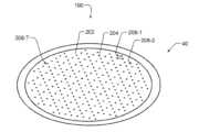
이제 도 2 및 도 3을 참조하면, 샤워헤드 (40) 의 상부 표면 (190) 및 하부 표면 (194) 의 사시도들이 각각 도시된다. 샤워헤드 (40) 는 복수의 쓰루홀들 (204) 을 포함하는 플라즈마-대면 표면 (202) 을 포함한다. 일부 예들에서, 플라즈마-대면 표면 (202) 은 원형이지만, 다른 형상들이 사용될 수 있다. 일부 예들에서, 플라즈마-대면 표면 (202) 은 대략 400 mm의 직경을 갖지만, 다른 직경들이 사용될 수도 있다.Referring now to FIGS. 2 and 3, perspective views of an upper surface (190) and a lower surface (194) of a showerhead (40) are respectively illustrated. The showerhead (40) includes a plasma-facing surface (202) including a plurality of through holes (204). In some examples, the plasma-facing surface (202) is circular, although other shapes may be used. In some examples, the plasma-facing surface (202) has a diameter of approximately 400 mm, although other diameters may be used.
일부 예들에서, 쓰루홀들 (204) 은 샤워헤드 (40) 의 상부 표면 (190) 으로부터 샤워헤드의 하부 표면 (194) 으로 연장한다. 일부 예들에서, 쓰루홀들 (204) 은 그룹들 (208-1, 208-2, …, 및 208-T) (집합적으로 쓰루홀들 (208) 의 그룹들) 로 배열되고, 그룹들 각각은 R 개의 쓰루홀들을 포함하고, R 및 T는 1보다 큰 정수들이다. 다른 예들에서, R은 1이다. 이 예에서, 쓰루홀들 (208) 의 그룹들 각각은 삼각형 구성으로 배열되는 3 개의 쓰루홀들 (204) 을 포함하지만, 다른 형상들 및 수들의 쓰루홀들이 사용될 수 있다. 일부 예들에서, 쓰루홀들 (208) 의 그룹들은 도 4에 가장 잘 보이는 육각형 패턴으로 배열된다. 삼각형 기반 패턴에서, 쓰루홀들은 반-이격된 삼각형 패턴으로 배열되거나 주입기 각각의 주위에 방사상으로 배열될 수도 있다. 또 다른 예시적인 패턴에서, 쓰루홀들은 주입기 각각의 주위에 방사상으로 (예를 들어, 원형 기반 패턴으로) 배열된다.In some examples, the through-holes (204) extend from an upper surface (190) of the showerhead (40) to a lower surface (194) of the showerhead. In some examples, the through-holes (204) are arranged in groups (208-1, 208-2, ..., and 208-T) (collectively groups of through-holes (208)), each of the groups including R through-holes, where R and T are integers greater than 1. In other examples, R is 1. In this example, each of the groups of through-holes (208) includes three through-holes (204) arranged in a triangular configuration, although other shapes and numbers of through-holes may be used. In some examples, the groups of through-holes (208) are arranged in a hexagonal pattern, best seen in FIG. 4. In a triangle-based pattern, the through-holes may be arranged in a semi-spaced triangular pattern or may be arranged radially around each injector. In another exemplary pattern, the through-holes are arranged radially around each injector (e.g., in a circular-based pattern).
전구체 가스가 샤워헤드 (40) 의 내부에 위치된 가스 플레넘 (미도시) 에 공급된다. 전구체 가스는 복수의 주입기들 (244) 을 통해 가스 플레넘을 빠져 나간다. 일부 예들에서, 복수의 주입기들 (244) 각각은 제한된 오리피스 (orifice) 를 포함한다. 일부 예들에서, 쓰루홀들 (208) 의 그룹들 각각은 복수의 주입기들 (244) 중 적어도 하나를 포함한다. 그룹들 (208) 중 미리 결정된 하나의 쓰루홀들 (204) 각각은 임의의 다른 주입기들 (244) 보다 주입기들 (244) 중 연관된 하나 (즉, 그룹 (208) 이 주위에 클러스터링되는 (clustered) 주입기) 에 보다 가깝다. 도 3에 도시된 바와 같이, 가스 주입기 노즐들 (248) 은 주입기들 (244) 의 각각 상에 배열될 수도 있다. 노즐들 (248) 은 주입기들 (244) 로부터 하향으로 연장한다. 예시적인 목적들을 위해 몇 개의 노즐들 (248) 만이 도시되지만, 주입기들 (244) 각각은 노즐들 (248) 각각을 가질 수도 있다.A precursor gas is supplied to a gas plenum (not shown) located within the showerhead (40). The precursor gas exits the gas plenum through a plurality of injectors (244). In some examples, each of the plurality of injectors (244) includes a restricted orifice. In some examples, each of the groups of through-holes (208) includes at least one of the plurality of injectors (244). Each of the predetermined one of the through-holes (204) of the groups (208) is closer to an associated one of the injectors (244) (i.e., an injector around which the group (208) is clustered) than to any of the other injectors (244). As illustrated in FIG. 3, the gas injector nozzles (248) may be arranged on each of the injectors (244). Nozzles (248) extend downward from the injectors (244). For illustrative purposes, only a few nozzles (248) are shown, but each of the injectors (244) may have its own nozzles (248).
샤워헤드 (40) 는 함께 연결되는 복수의 층들로 이루어질 수 있다. 보다 많은 층들이 부가적인 플레넘들을 생성하기 위해 추가될 수도 있다. 일부 예들에서, 샤워헤드 (40) 는 합리적인 비용으로 복잡하고 독특한 기하구조들을 가능하게 하기 위해 진공 브레이징 (brazing), TIG (Tungsten Inert Gas) 용접, 또는 전자 빔 용접을 사용하여 제작될 수 있다. 진공 브레이즈 (braze) 접합은 샤워헤드로 하여금 플레이트 각각 사이에 브레이즈의 층을 갖는 플레이트들로 절단된 홈들을 갖는 평평한 플레이트들로 머시닝되게 (machined) 한다. 용접 기법들은 시일링 (sealing) 을 필요로 하는 모든 영역들에 접근하기 위해 용접에 대해 보다 복잡한 하위 컴포넌트들을 필요로 한다. 포스트들 및 대응하는 홀들은 시일링 영역을 용접에 접근 가능한 부분의 표면으로 상승시키도록 머시닝될 수도 있다.The showerhead (40) may be comprised of multiple layers joined together. More layers may be added to create additional plenums. In some examples, the showerhead (40) may be fabricated using vacuum brazing, Tungsten Inert Gas (TIG) welding, or electron beam welding to enable complex and unique geometries at a reasonable cost. Vacuum braze welding allows the showerhead to be machined from flat plates with grooves cut into the plates with a layer of braze between each plate. Welding techniques require more complex subcomponents to weld in order to access all areas requiring sealing. Posts and corresponding holes may be machined to elevate the sealing area to the surface of the portion accessible for welding.
이제 도 4를 참조하면, 쓰루홀들 (204) 중 선택된 쓰루홀들은 라디칼들의 전달을 변경/조정하기 위해 상이하게 사이즈가 정해지는 (sized) 직경들을 갖는다. A, B 또는 C로 라벨링되지 (labeled) 않은 쓰루홀들 (204) 각각은 공칭 유형이고, 이하에 더 기술될 공칭 직경 치수를 갖는다. 유형 A, B, 또는 C로 라벨링되는 쓰루홀들 (204) 은 이하에 더 기술될 바와 같이 공칭 직경 치수와 상이한 직경 치수를 갖는다.Referring now to FIG. 4, selected through-holes (204) have differently sized diameters to alter/adjust the delivery of radicals. Each of the through-holes (204) that are not labeled A, B, or C are of a nominal type and have a nominal diameter dimension as further described below. The through-holes (204) that are labeled Type A, B, or C have a diameter dimension that is different from the nominal diameter dimension as further described below.
일부 예들에서, 유형들 A, B 및 C에 대해, 평균 사이즈는 미리 결정된 비 (Davg_typeX)4/(Davg_nom)4 = 비 +/- 0.01”를 따르고, Davg_typeX는 유형 X (이 예에서 A 또는 B 또는 C일 수 있음) 의 평균 직경이고, Davg_nom은 공칭 유형의 평균 직경이다. 일부 예들에서, 유형 A에 대한 비는 1.3 내지 1.6의 범위이다. 일부 예들에서, 유형 B에 대한 비는 0.8 내지 1.0의 범위이다. 일부 예들에서, 유형 C에 대한 비는 1.0 내지 1.2의 범위이다. 인식할 수 있는 바와 같이 홀 사이즈들의 다른 조합들이 동일한 전체 샤워헤드 플로우 분포를 달성할 수 있다. 전술한 예는 원형 챔버 내의 삼각형 패턴의 방위각적 불균일성을 보정한다. 홀 사이즈 비들은 또한 기판 상의 증착의 방사상 균일성을 변화시키기 위해 방사상으로 조절될 수 있다. 예를 들어, 샤워헤드 (40) 를 통해 2 개 이상의 상이한 가스들을 제공하도록 구성된 기판 프로세싱 시스템들에 대해, 상기 기술한 바와 같이 상이한 가스들에 대응하는 홀 사이즈 비들을 조절하는 것은 샤워헤드 밖으로 그리고 프로세싱 챔버 내로 흐르는 가스들의 양들 사이의 비를 변화시킨다. 이 방식에서, 홀 사이즈 비들은 특정한 영역들에서 반응물질 비를 조절하고 웨이퍼 불균일성들을 보정하도록 조정될 수 있다. 일부 예들에서, 주입기들 (244) (및/또는 각각의 노즐들 (248)) 의 직경들은 동일한 방식으로 가스 플로우 비들을 조절하도록 변화될 수도 있다. 그러나, 주입기들 (244) 보다 쓰루홀들 (204) 의 수가 상당히 보다 많기 때문에, 쓰루홀들 (204) 의 직경들을 변화시키는 것은 가스 플로우 비의 보다 미세한 튜닝을 용이하게 한다.In some examples, for types A, B and C, the average size follows a predetermined ratio (Davg_typeX)4 /(Davg_nom)4 = ratio +/- 0.01”, where Davg_typeX is the average diameter of type X (which may be A or B or C in this example) and Davg_nom is the average diameter of the nominal type. In some examples, the ratio for type A is in the range of 1.3 to 1.6. In some examples, the ratio for type B is in the range of 0.8 to 1.0. In some examples, the ratio for type C is in the range of 1.0 to 1.2. As can be appreciated, other combinations of hole sizes can achieve the same overall showerhead flow distribution. The above example compensates for the azimuthal non-uniformity of the triangular pattern within the circular chamber. The hole size ratios can also be adjusted radially to vary the radial uniformity of the deposition on the substrate. For example, showerhead (40) For substrate processing systems configured to provide two or more different gases through the showerhead, adjusting the hole size ratios corresponding to the different gases as described above changes the ratio between the amounts of gases flowing out of the showerhead and into the processing chamber. In this manner, the hole size ratios can be adjusted to control the reactant ratio in specific regions and to compensate for wafer non-uniformities. In some examples, the diameters of the injectors (244) (and/or each of the nozzles (248)) may also be varied to control the gas flow ratios in the same manner. However, since there are significantly more through-holes (204) than injectors (244), varying the diameters of the through-holes (204) facilitates finer tuning of the gas flow ratio.
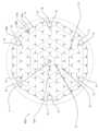
도 4의 예에서, 총 85 개의 주입기들 (244) 과 대응하는 개수의 그룹들의 쓰루홀들 (204) 이 있다. 플라즈마-대면 표면 (202) 의 방사상으로 내측 부분 (252) 내에 위치된 쓰루홀들 (204) 중 일부는 유형 C이다. 플라즈마-대면 표면 (202) 의 방사상으로 외측 부분 (254) 내에 위치된 쓰루홀들 (204) 중 일부는 유형 A 및 유형 B이다. 일부 예들에서, 쓰루홀들 (204) 중 9 개는 유형 C로 선택된다. 일부 예들에서, 쓰루홀들 (204) 중 36 개는 유형 B로 선택된다. 일부 예들에서, 쓰루홀들 (204) 중 6 개는 유형 A로 선택된다. 일부 예들에서, 6 개의 유형 B 쓰루홀들 및 1 개의 유형 A 쓰루홀들은 6 개의 60 도 파이 형상 슬라이스들 (250) 각각에 배열된다.In the example of FIG. 4, there are a total of 85 injectors (244) and a corresponding number of groups of through-holes (204). Some of the through-holes (204) located within the radially inner portion (252) of the plasma-facing surface (202) are of type C. Some of the through-holes (204) located within the radially outer portion (254) of the plasma-facing surface (202) are of type A and type B. In some examples, nine of the through-holes (204) are selected as type C. In some examples, thirty-six of the through-holes (204) are selected as type B. In some examples, six of the through-holes (204) are selected as type A. In some examples, six type B through-holes and one type A through-hole are arranged in each of six 60 degree pie-shaped slices (250).
가스 주입기들은 중심 주입기와 그 주위에 반복된 패턴을 갖는 원형 보어 (bore) 내에 배열된다. 도 4에서, 단일의, 중심 그룹 (256) 은 총 85 개의 그룹들에 대해 각각의 동심 육각형 영역들에서 6, 12, 18, 24 및 24 개의 그룹으로 둘러싸여 있다. 예를 들어, 도 4에 도시된 바와 같이, 그룹 (256) 은 제 1 육각형 영역 (258) 내의 6 개의 삼각형 그룹들에 의해 둘러싸여 있다. 제 2 육각형 영역 (260) 이 12 개의 삼각형 그룹들을 포함한다. 제 3 육각형 영역 (262) 이 18 개의 삼각형 그룹들을 포함한다. 제 4 육각형 영역 (264) 및 제 5 육각형 영역 (266) 각각이 24 개의 삼각형 그룹들을 포함한다. 가스 주입기 주위의 쓰루홀들의 패턴이 85 개의 그룹들의 쓰루홀들을 포함하지만, 패턴은 6 개의 증분들 (즉, 연속적인 주위 영역 각각이 인접한 내측 영역보다 6 개 더 많은 그룹들을 갖는 6 개의 증가하는 패턴) 로 변화될 수 있다. 대안적인 패턴들은 6 개 또는 8 개의 증가하는 패턴을 갖는 방사상 패턴을 포함한다. 6 개의 증가하는 패턴을 갖는 방사상 패턴이 61, 91, 127, 또는 169 개의 주입기들을 포함한다. 8 개의 증가하는 패턴을 갖는 방사상 패턴이 81, 121, 또는 169 개의 주입기들을 포함한다. 일부 예들에서, 공칭 유형은 0.06” 내지 0.40”의 치수를 갖는다. 공칭 홀 직경은 플로우 분포로 하여금 다른 챔버 기하구조에 의해 지배되지 않고 쓰루홀들 (204) 로 제어되게 하도록 플로우, 가스, 및 압력 조건들에 필요한 압력 강하에 종속될 수도 있다. 홀 직경은 또한 상부 챔버 (20) 내로의 전구체 가스들의 역 확산을 방지하기 위해 목표된 플로우 레이트, 압력, 및 가스 종에 종속될 수도 있다.The gas injectors are arranged within a circular bore having a central injector and a repeating pattern around it. In FIG. 4, a single, central group (256) is surrounded by groups of 6, 12, 18, 24, and 24 in each of the concentric hexagonal regions for a total of 85 groups. For example, as shown in FIG. 4, group (256) is surrounded by 6 triangular groups within the first hexagonal region (258). The second hexagonal region (260) includes 12 triangular groups. The third hexagonal region (262) includes 18 triangular groups. The fourth hexagonal region (264) and the fifth hexagonal region (266) each include 24 triangular groups. While the pattern of through-holes around the gas injector includes 85 groups of through-holes, the pattern can vary in increments of six (i.e., a six incremental pattern where each successive peripheral region has six more groups than the adjacent inner region). Alternative patterns include a radial pattern having six or eight incremental patterns. A radial pattern having six incremental patterns includes 61, 91, 127, or 169 injectors. A radial pattern having eight incremental patterns includes 81, 121, or 169 injectors. In some examples, the nominal type has a dimension of 0.06" to 0.40". The nominal hole diameter may depend on the pressure drop required for flow, gas, and pressure conditions to allow the flow distribution to be controlled by the through-holes (204) without being dominated by other chamber geometries. The hole diameter may also depend on the targeted flow rate, pressure, and gas species to prevent back diffusion of precursor gases into the upper chamber (20).
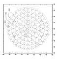
도 5는 본 개시에 따른 샤워헤드 (500) 의 예시적인 하면도를 도시한다. 이 예에서, 쓰루홀들 (504) 은 각각의 주입기들 (512) 주위에 클러스터링된 그룹들 (508) 의 삼각형 기반 패턴으로 배열된다. 중심 그룹 (516) 은 각각 6 개의 그룹들 (508), 12 개의 그룹들 (508), 18 개의 그룹들 (508), 24 개의 그룹들 (508), 및 24 개의 그룹들 (508) 의 각각의 연속적인 육각형 링들에 의해 둘러싸여 있다. 이 예에서, 그룹들 (508) 의 최외각 육각형 링은 또한 주입기들 (512) 각각의 주위에 클러스터링된 그룹들 (508) 중 특정한 그룹과 연관되지 않은 부가적인 쓰루홀들 (540) 을 포함한다. 대신, 쓰루홀들 (540) 은 최외각 육각형 링의 그룹들 (508) 의 패턴 내의 갭들 내에 배열된다. “링들”로 지칭되지만, 그룹들 (508) 은 도 4에 도시된 방식과 유사한 연속적인 육각형 패턴들로 배열된다.FIG. 5 illustrates an exemplary bottom view of a showerhead (500) according to the present disclosure. In this example, the through-holes (504) are arranged in a triangular based pattern of groups (508) clustered around each of the injectors (512). A central group (516) is surrounded by successive hexagonal rings of six groups (508), twelve groups (508), eighteen groups (508), twenty-four groups (508), and twenty-four groups (508), respectively. In this example, the outermost hexagonal ring of the groups (508) also includes additional through-holes (540) that are not associated with a particular group of the groups (508) clustered around each of the injectors (512). Instead, the through-holes (540) are arranged within gaps within the pattern of groups (508) of outermost hexagonal rings. Although referred to as “rings,” the groups (508) are arranged in a continuous hexagonal pattern similar to that illustrated in FIG. 4.
도 4에 기술된 예와 유사하게, 쓰루홀들 (504 및 540) 중 선택된 쓰루홀들은 도 5에 도시된 바와 같이 라디칼들의 전달을 변경/조정하기 위해 상이하게 사이즈가 정해지는 직경들을 갖는다. 이 예에서, (도 5의 각각의 쓰루홀들과 연결되는 프로파일들 A 내지 F 각각에 의해 나타낸 바와 같이) A, B, C, D, E, F 또는 G로 라벨링되지 않는 쓰루홀들 (504 및 540) 각각은 공칭 유형이고, 이하에 더 기술될 공칭 직경 치수를 갖는다. 유형 A, B 또는 C로 라벨링되는 쓰루홀들 (504 및 540) 은 이하에 더 기술될 바와 같이 공칭 직경 치수와 상이한 직경 치수를 갖는다.Similar to the example described in FIG. 4, selected ones of the through-holes (504 and 540) have diameters that are sized differently to alter/adjust the delivery of radicals, as illustrated in FIG. 5. In this example, each of the through-holes (504 and 540) that are not labeled A, B, C, D, E, F or G (as represented by profiles A through F associated with each of the through-holes in FIG. 5) are of nominal type and have a nominal diameter dimension as further described below. The through-holes (504 and 540) that are labeled as type A, B or C have a diameter dimension that is different from the nominal diameter dimension as further described below.
일부 예들에서, 유형들 A, B, C, D, E, F, 및 G에 대해, 평균 사이즈는 미리 결정된 비 (Davg_typeX)4/(Davg_nom)4 = 비 +/- 0.01”를 따르고, Davg_typeX는 유형 X (이 예에서 A, B, C, D, E, F, 또는 G일 수 있음) 의 평균 직경이고, Davg_nom은 공칭 유형의 평균 직경이다. 일부 예들에서, 유형 A에 대한 비는 1.3 내지 1.6의 범위이다. 일부 예들에서, 유형 B에 대한 비는 1.1 내지 1.4의 범위이다. 일부 예들에서, 유형 C에 대한 비는 1.1 내지 1.4의 범위이다. 일부 예들에서, 유형 D에 대한 비는 1.1 내지 1.4의 범위이다. 일부 예들에서, 유형 E에 대한 비는 1.2 내지 1.5의 범위이다. 일부 예들에서, 유형 F에 대한 비는 0.7 내지 1.0의 범위이다. 일부 예들에서, 유형 G에 대한 비는 0.7 내지 1.0의 범위이다.In some examples, for types A, B, C, D, E, F, and G, the average size follows a predetermined ratio (Davg_typeX)4 /(Davg_nom)4 = ratio +/- 0.01”, where Davg_typeX is the average diameter of type X (which may be A, B, C, D, E, F, or G in this example), and Davg_nom is the average diameter of the nominal type. In some examples, the ratio for type A is in the range of 1.3 to 1.6. In some examples, the ratio for type B is in the range of 1.1 to 1.4. In some examples, the ratio for type C is in the range of 1.1 to 1.4. In some examples, the ratio for type D is in the range of 1.1 to 1.4. In some examples, the ratio for type E is in the range of 1.2 to 1.5. In some examples, the ratio for type F is The range is 0.7 to 1.0. In some examples, the ratio for type G is in the range of 0.7 to 1.0.
인식할 수 있는 바와 같이 홀 사이즈들의 다른 조합들이 동일한 전체 샤워헤드 플로우 분포를 달성할 수 있다. 홀 사이즈 비들은 또한 기판 상의 증착의 방사상 균일성을 변화시키기 위해 방사상으로 조절될 수 있다. 이 방식에서, 홀 사이즈 비들은 특정한 영역들에서 반응물질 비를 조절하고 웨이퍼 불균일성들을 보정하도록 조정될 수 있다.As can be appreciated, different combinations of hole sizes can achieve the same overall showerhead flow distribution. The hole size ratios can also be radially adjusted to vary the radial uniformity of the deposition on the substrate. In this manner, the hole size ratios can be adjusted to control the reactant ratio in specific areas and to compensate for wafer non-uniformities.
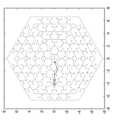
도 6a, 도 6b, 및 도 6c는 본 개시에 따른 다른 예시적인 홀 패턴들을 예시한다. 도 6a에서, 쓰루홀들 (600) 은 각각의 주입기들 (608) 주위에 클러스터링된 그룹들 (604) 의 삼각형 기반 패턴으로 배열된다. 중심 그룹 (612) 이 각각 6 개, 12 개, 18 개, 24 개, 및 30 개의 그룹들 (604) 을 포함하는 (즉, 6 개의 증가하는 패턴으로) 5 개의 연속적인 원형 영역들에 의해 둘러싸여 있다. 도 6b 및 도 6c 각각에서, 중심 그룹 (616) 은 6 개, 12 개, 18 개, 24 개, 및 24 개의 그룹들 (604) 을 포함하는 각각의 5 개의 연속적인 육각형 영역들에 의해 둘러싸여 있다.FIGS. 6A, 6B, and 6C illustrate other exemplary hole patterns according to the present disclosure. In FIG. 6A, the through-holes (600) are arranged in a triangular based pattern of groups (604) clustered around each of the injectors (608). A central group (612) is surrounded by five consecutive circular regions containing 6, 12, 18, 24, and 30 groups (604), respectively (i.e., in an increasing pattern of 6). In FIGS. 6B and 6C , respectively, a central group (616) is surrounded by five consecutive hexagonal regions containing 6, 12, 18, 24, and 24 groups (604), respectively.
도 6a, 도 6b, 및 도 6c에 도시된 예들에서, 쓰루홀들 (600) 중 선택된 쓰루홀들의 직경들은 도 4 및 도 5d에 기술된 것과 유사한 방식으로 라디칼들의 전달을 변경/조정하기 위해 상이하게 사이즈가 정해질 수도 있다. 즉, 유형 X의 쓰루홀들 (600) 중 선택된 쓰루홀들은 쓰루홀들 (600) 의 공칭 직경 치수와 상이한 직경 치수를 갖는다. 예를 들어, 쓰루홀들 (600) 중 선택된 쓰루홀들은 미리 결정된 비 (Davg_typeX)4/(Davg_nom)4 = 비 +/- 0.01”를 따르는 평균 사이즈를 갖고, Davg_typeX는 유형 X의 평균 직경이고, Davg_nom은 공칭 유형의 평균 직경이다. 이 방식에서, 홀 사이즈 비들은 상기 보다 상세히 기술된 바와 같이 특정한 영역들에서 반응물질 비를 조절하고 웨이퍼 불균일성들을 보정하도록 조정될 수 있다.In the examples illustrated in FIGS. 6A, 6B, and 6C, the diameters of selected ones of the through-holes (600) may be sized differently to alter/adjust the delivery of radicals in a manner similar to that described in FIGS. 4 and 5D. That is, the selected ones of the through-holes (600) of type X have a diameter dimension that is different from the nominal diameter dimension of the through-holes (600). For example, the selected ones of the through-holes (600) may have an average size that follows a predetermined ratio (Davg_typeX)4 /(Davg_nom)4 = ratio +/- 0.01”, where Davg_typeX is the average diameter of type X and Davg_nom is the average diameter of nominal type. In this manner, the hole size ratios can be adjusted to control the reactant ratio in specific regions and to compensate for wafer non-uniformities, as described in more detail above.
전술한 기술은 본질적으로 단지 예시이고, 어떠한 방식으로도 본 개시, 이의 적용예, 또는 사용들을 제한하도록 의도되지 않는다. 본 개시의 광범위한 교시들은 다양한 형태들로 구현될 수 있다. 따라서, 본 개시가 특정한 예들을 포함하지만, 본 개시의 진정한 범위는 다른 수정들이 도면들, 명세서, 및 이하의 청구항들의 연구에 따라 분명해질 것이기 때문에 이렇게 제한되지 않아야 한다. 방법의 하나 이상의 단계들은 본 개시의 원리들을 변경하지 않고 상이한 순서로 (또는 동시에) 실행될 수도 있다는 것이 이해되어야 한다. 또한, 실시예들 각각이 특정한 피처들을 갖는 것으로 상기 기술되었지만, 본 개시의 임의의 실시예에 대해 기술된 이들 피처들 중 임의의 하나 이상은, 조합이 명시적으로 기술되지 않더라도 임의의 다른 실시예들의 피처들에서 그리고/또는 피처들과 조합하여 구현될 수 있다. 즉, 기술된 실시예들은 상호 배타적이지 않고, 하나 이상의 실시예들의 또 다른 실시예들과의 치환들이 본 개시의 범위 내에 남는다.The foregoing description is merely illustrative in nature and is not intended to limit the present disclosure, its applications, or uses in any way. The broad teachings of the present disclosure can be implemented in many different forms. Therefore, while the present disclosure includes specific examples, the true scope of the present disclosure should not be so limited, as other modifications will become apparent upon study of the drawings, the specification, and the claims below. It should be understood that one or more of the steps of the method may be performed in different order (or simultaneously) without altering the principles of the present disclosure. Furthermore, while each of the embodiments has been described above as having certain features, any one or more of those features described for any embodiment of the present disclosure may be implemented in and/or in combination with the features of any other embodiments, even if the combination is not explicitly described. In other words, the described embodiments are not mutually exclusive, and substitution of one or more embodiments with other embodiments remains within the scope of the present disclosure.
엘리먼트들 간 (예를 들어, 모듈들, 회로 엘리먼트들, 반도체 층들, 등 간) 의 공간적 및 기능적 관계들은, “연결된 (connected)”, “인게이지된 (engaged)”, “커플링된 (coupled)”, “인접한 (adjacent)”, “옆에 (next to)”, “상단에 (on top of)”, “위에 (above)”, “아래에 (below)”, 및 “배치된 (disposed)” 을 포함하는, 다양한 용어들을 사용하여 기술된다. “직접적 (direct)” 으로 명시적으로 기술되지 않는 한, 제 1 엘리먼트와 제 2 엘리먼트 간의 관계가 상기 개시에서 기술될 때, 그 관계는 제 1 엘리먼트와 제 2 엘리먼트 사이에 다른 중개하는 엘리먼트들이 존재하지 않는 직접적인 관계일 수 있지만, 또한 제 1 엘리먼트와 제 2 엘리먼트 사이에 (공간적으로 또는 기능적으로) 하나 이상의 중개하는 엘리먼트들이 존재하는 간접적인 관계일 수 있다. 본 명세서에서 논의된 바와 같이, 구 (phrase) A, B, 및 C 중 적어도 하나는 비배타적인 논리 OR를 사용하여 논리적으로 (A 또는 B 또는 C) 를 의미하는 것으로 해석되어야 하고, “적어도 하나의 A, 적어도 하나의 B, 및 적어도 하나의 C” 를 의미하도록 해석되지 않아야 한다.Spatial and functional relationships between elements (e.g., between modules, circuit elements, semiconductor layers, etc.) are described using various terms, including “connected,” “engaged,” “coupled,” “adjacent,” “next to,” “on top of,” “above,” “below,” and “disposed.” Unless explicitly described as “direct,” when a relationship between a first element and a second element is described in the disclosure, the relationship can be a direct relationship where no other intervening elements exist between the first element and the second element, but can also be an indirect relationship where one or more intervening elements (either spatially or functionally) exist between the first element and the second element. As discussed herein, the phrases A, B, and C should be interpreted to logically mean (A or B or C) using a non-exclusive logical OR, and not to mean “at least one A, at least one B, and at least one C.”
일부 구현예들에서, 제어기는, 상기 기술된 예들의 일부일 수도 있는 시스템의 일부이다. 이러한 시스템들은, 프로세싱 툴 또는 툴들, 챔버 또는 챔버들, 프로세싱용 플랫폼 또는 플랫폼들, 및/또는 특정 프로세싱 컴포넌트들 (웨이퍼 페데스탈, 가스 플로우 시스템, 등) 을 포함하는, 반도체 프로세싱 장비를 포함할 수 있다. 이들 시스템들은 반도체 웨이퍼 또는 기판의 프로세싱 전에, 프로세싱 동안에 그리고 프로세싱 후에 그들의 동작을 제어하기 위해 전자장치들에 통합될 수도 있다. 전자장치들은 시스템 또는 시스템들의 다양한 컴포넌트들 또는 하위부분들을 제어할 수도 있는 “제어기”로서 지칭될 수도 있다. 제어기는, 프로세싱 조건들 및/또는 시스템의 유형에 따라서, 프로세싱 가스들의 전달, 온도 설정사항들 (예를 들어, 가열 및/또는 냉각), 압력 설정사항들, 진공 설정사항들, 전력 설정사항들, 무선 주파수 (RF) 생성기 설정사항들, RF 매칭 회로 설정사항들, 주파수 설정사항들, 플로우 레이트 설정사항들, 유체 전달 설정사항들, 위치 및 동작 설정사항들, 툴 및 다른 이송 툴들 및/또는 특정 시스템과 연결되거나 인터페이싱된 로드록들 내외로의 웨이퍼 이송들을 포함하는, 본 명세서에 개시된 프로세스들 중 임의의 프로세스들을 제어하도록 프로그래밍될 수도 있다.In some implementations, the controller is part of a system, which may be part of the examples described above. These systems may include semiconductor processing equipment, including a processing tool or tools, a chamber or chambers, a platform or platforms for processing, and/or certain processing components (such as a wafer pedestal, a gas flow system, etc.). These systems may be integrated with electronics to control their operation before, during, and after processing of a semiconductor wafer or substrate. The electronics may be referred to as a “controller” that may control various components or sub-portions of the system or systems. The controller may be programmed to control any of the processes disclosed herein, including, depending on processing conditions and/or the type of system, delivery of processing gases, temperature settings (e.g., heating and/or cooling), pressure settings, vacuum settings, power settings, radio frequency (RF) generator settings, RF matching circuit settings, frequency settings, flow rate settings, fluid delivery settings, position and motion settings, wafer transfers into and out of tools and other transport tools and/or load locks connected to or interfaced with a particular system.
일반적으로 말하면, 제어기는 인스트럭션들을 수신하고, 인스트럭션들을 발행하고, 동작을 제어하고, 세정 동작들을 인에이블하고, 엔드 포인트 측정들을 인에이블하는 등을 하는 다양한 집적 회로들, 로직, 메모리, 및/또는 소프트웨어를 갖는 전자장치들로서 규정될 수도 있다. 집적 회로들은 프로그램 인스트럭션들을 저장하는 펌웨어의 형태의 칩들, 디지털 신호 프로세서들 (DSPs), ASICs (Application Specific Integrated Circuits) 으로서 규정되는 칩들, 및/또는 프로그램 인스트럭션들 (예를 들어, 소프트웨어) 을 실행하는 하나 이상의 마이크로프로세서들, 또는 마이크로제어기들을 포함할 수도 있다. 프로그램 인스트럭션들은 반도체 웨이퍼 상에서 또는 반도체 웨이퍼에 대한 특정 프로세스를 실행하기 위한 동작 파라미터들을 규정하는, 다양한 개별 설정사항들 (또는 프로그램 파일들) 의 형태로 제어기로 또는 시스템으로 전달되는 인스트럭션들일 수도 있다. 일부 실시예들에서, 동작 파라미터들은 하나 이상의 층들, 재료들, 금속들, 옥사이드들, 실리콘, 실리콘 다이옥사이드, 표면들, 회로들, 및/또는 웨이퍼의 다이들의 제조 동안에 하나 이상의 프로세싱 단계들을 달성하도록 프로세스 엔지니어들에 의해 규정된 레시피의 일부일 수도 있다.Generally speaking, a controller may be defined as an electronic device having various integrated circuits, logic, memory, and/or software that receives instructions, issues instructions, controls operations, enables cleaning operations, enables end point measurements, etc. The integrated circuits may include chips in the form of firmware that store program instructions, chips defined as digital signal processors (DSPs), chips defined as Application Specific Integrated Circuits (ASICs), and/or one or more microprocessors or microcontrollers that execute program instructions (e.g., software). The program instructions may be instructions that are communicated to the controller or system in the form of various individual settings (or program files) that specify operational parameters for executing a particular process on or for a semiconductor wafer. In some embodiments, the operating parameters may be part of a recipe defined by process engineers to accomplish one or more processing steps during the fabrication of one or more layers, materials, metals, oxides, silicon, silicon dioxide, surfaces, circuits, and/or dies of a wafer.
제어기는, 일부 구현예들에서, 시스템에 통합되거나, 시스템에 커플링되거나, 이와 달리 시스템에 네트워킹되거나, 또는 이들의 조합으로 될 수 있는 컴퓨터에 커플링되거나 이의 일부일 수도 있다. 예를 들어, 제어기는 웨이퍼 프로세싱의 원격 액세스를 가능하게 할 수 있는 공장 (fab) 호스트 컴퓨터 시스템의 전부 또는 일부이거나 “클라우드” 내에 있을 수도 있다. 컴퓨터는 제조 동작들의 현 진행을 모니터링하고, 과거 제조 동작들의 이력을 조사하고, 복수의 제조 동작들로부터 경향들 또는 성능 계측치들을 조사하고, 현 프로세싱의 파라미터들을 변경하고, 현 프로세싱을 따르는 프로세싱 단계들을 설정하고, 또는 새로운 프로세스를 시작하기 위해서 시스템으로의 원격 액세스를 인에이블할 수도 있다. 일부 예들에서, 원격 컴퓨터 (예를 들어, 서버) 는 로컬 네트워크 또는 인터넷을 포함할 수도 있는 네트워크를 통해서 프로세스 레시피들을 시스템에 제공할 수 있다. 원격 컴퓨터는 차후에 원격 컴퓨터로부터 시스템으로 전달되는 파라미터들 및/또는 설정사항들의 입력 또는 프로그래밍을 인에이블하는 사용자 인터페이스를 포함할 수도 있다. 일부 예들에서, 제어기는 하나 이상의 동작들 동안에 수행될 프로세싱 단계들 각각에 대한 파라미터들을 특정하는, 데이터의 형태의 인스트럭션들을 수신한다. 파라미터들은 제어기가 제어하거나 인터페이싱하도록 구성된 툴의 유형 및 수행될 프로세스의 유형에 특정적일 수도 있다는 것이 이해되어야 한다. 따라서, 상기 기술된 바와 같이, 제어기는 예컨대 본 명세서에 기술된 프로세스들 및 제어들과 같은, 공동의 목적을 향해 함께 네트워킹되고 작동하는 하나 이상의 개별 제어기들을 포함함으로써 분산될 수도 있다. 이러한 목적들을 위한 분산된 제어기의 예는 챔버 상의 프로세스를 제어하도록 조합되는, 원격으로 위치한 (예컨대 플랫폼 레벨에서 또는 원격 컴퓨터의 일부로서) 하나 이상의 집적 회로들과 통신하는 챔버 상의 하나 이상의 집적 회로들일 것이다.The controller may be coupled to or part of a computer, which may be integrated into the system, coupled to the system, otherwise networked to the system, or a combination thereof, in some implementations. For example, the controller may be all or part of a fab host computer system that may enable remote access to the wafer processing, or may be in the “cloud.” The computer may enable remote access to the system to monitor the current progress of manufacturing operations, examine the history of past manufacturing operations, examine trends or performance metrics from multiple manufacturing operations, change parameters of current processing, set processing steps to follow current processing, or initiate a new process. In some examples, a remote computer (e.g., a server) may provide process recipes to the system over a network, which may include a local network or the Internet. The remote computer may include a user interface that enables entry or programming of parameters and/or settings that are subsequently transmitted to the system from the remote computer. In some examples, the controller receives instructions in the form of data specifying parameters for each of the processing steps to be performed during one or more operations. It should be appreciated that the parameters may be specific to the type of tool that the controller is configured to control or interface with and the type of process to be performed. Thus, as described above, the controller may be distributed by including one or more individual controllers that are networked and operate together toward a common purpose, such as the processes and controls described herein. An example of a distributed controller for such purposes would be one or more integrated circuits on a chamber that communicate with one or more remotely located (e.g., at the platform level or as part of a remote computer) integrated circuits that are combined to control a process on the chamber.
비한정적으로, 예시적인 시스템들은 플라즈마 에칭 챔버 또는 모듈, 증착 챔버 또는 모듈, 스핀-린스 챔버 또는 모듈, 금속 도금 챔버 또는 모듈, 세정 챔버 또는 모듈, 베벨 에지 에칭 챔버 또는 모듈, PVD (Physical Vapor Deposition) 챔버 또는 모듈, CVD (Chemical Vapor Deposition) 챔버 또는 모듈, ALD (Atomic Layer Deposition) 챔버 또는 모듈, ALE (Atomic Layer Etch) 챔버 또는 모듈, 이온 주입 챔버 또는 모듈, 트랙 (track) 챔버 또는 모듈, 및 반도체 웨이퍼들의 제조 및/또는 제작 시에 사용되거나 연관될 수도 있는 임의의 다른 반도체 프로세싱 시스템들을 포함할 수도 있다.Without limitation, exemplary systems may include a plasma etch chamber or module, a deposition chamber or module, a spin-rinse chamber or module, a metal plating chamber or module, a cleaning chamber or module, a bevel edge etch chamber or module, a PVD (Physical Vapor Deposition) chamber or module, a CVD (Chemical Vapor Deposition) chamber or module, an ALD (Atomic Layer Deposition) chamber or module, an ALE (Atomic Layer Etch) chamber or module, an ion implantation chamber or module, a track chamber or module, and any other semiconductor processing systems that may be used in or associated with the manufacture and/or fabrication of semiconductor wafers.
상술한 바와 같이, 툴에 의해서 수행될 프로세스 단계 또는 단계들에 따라서, 제어기는, 반도체 제작 공장 내의 툴 위치들 및/또는 로드 포트들로부터 그리고 툴 위치들 및/또는 로드 포트들로 웨이퍼들의 컨테이너들을 이동시키는 재료 이송 시에 사용되는, 다른 툴 회로들 또는 모듈들, 다른 툴 컴포넌트들, 클러스터 툴들, 다른 툴 인터페이스들, 인접 툴들, 이웃하는 툴들, 공장 도처에 위치한 툴들, 메인 컴퓨터, 또 다른 제어기 또는 툴들 중 하나 이상과 통신할 수도 있다.As described above, depending on the process step or steps to be performed by the tool, the controller may communicate with one or more of other tool circuits or modules, other tool components, cluster tools, other tool interfaces, adjacent tools, neighboring tools, tools located throughout the factory, a main computer, another controller or tools used in material transport to and from tool locations and/or load ports within the semiconductor fabrication facility.
Claims (16)
Translated fromKorean하부 표면;
플라즈마-대면 상부 표면;
샤워헤드 내부에서 상기 하부 표면과 상기 상부 표면 사이에 규정된 가스 플레넘 (plenum);
상기 하부 표면 상에 분포된 복수의 주입기들로서, 상기 복수의 주입기들은 상기 가스 플레넘과 유체로 연통하는, 상기 복수의 주입기들;
복수의 가스 주입기 노즐들로서, 상기 복수의 가스 주입기 노즐들 각각은 상기 복수의 주입기들 중 대응하는 주입기와 정렬되고 그리고 가스가 상기 복수의 주입기들 및 상기 복수의 가스 주입기 노즐들을 통해 상기 샤워헤드 내부의 상기 가스 플레넘으로부터 상기 샤워헤드 아래의 볼륨으로 빠져나가도록 상기 하부 표면으로부터 아래로 연장하는, 상기 복수의 가스 주입기 노즐들; 및
상기 플라즈마-대면 상부 표면으로부터 상기 하부 표면으로 연장하는 복수의 쓰루홀들 (through holes) 로서, 상기 복수의 쓰루홀들은 복수의 제 1 쓰루홀들 및 복수의 제 2 쓰루홀들을 포함하고, 상기 제 1 쓰루홀들의 직경은 상기 제 2 쓰루홀들의 직경들과 상이하고, 상기 복수의 쓰루홀들은 상기 플라즈마-대면 상부 표면 위의 볼륨 및 상기 하부 표면 아래의 볼륨과 유체 연통하고,
상기 샤워헤드의 하부 표면 상에서, 상기 복수의 쓰루홀들은 복수의 개별 그룹 내에 위치하며, 상기 복수의 개별 그룹 각각은 상기 복수의 주입기들 중 각각의 주입기 주위에 분포된 상기 복수의 쓰루홀들 중 2 개 이상의 쓰루홀들을 포함하는, 상기 복수의 쓰루홀들을 포함하는, 샤워헤드.In a showerhead for a substrate processing system,
lower surface;
Plasma-facing upper surface;
A gas plenum defined between the lower surface and the upper surface within the showerhead;
A plurality of injectors distributed on the lower surface, the plurality of injectors being in fluid communication with the gas plenum;
A plurality of gas injector nozzles, each of the plurality of gas injector nozzles being aligned with a corresponding injector among the plurality of injectors and extending downwardly from the lower surface such that gas is emitted from the gas plenum within the showerhead through the plurality of injectors and the plurality of gas injector nozzles into a volume below the showerhead; and
A plurality of through holes extending from the plasma-facing upper surface to the lower surface, the plurality of through holes including a plurality of first through holes and a plurality of second through holes, wherein diameters of the first through holes are different from diameters of the second through holes, and the plurality of through holes are in fluid communication with a volume above the plasma-facing upper surface and a volume below the lower surface.
A showerhead comprising a plurality of through-holes, wherein on a lower surface of the showerhead, the plurality of through-holes are positioned within a plurality of individual groups, each of the plurality of individual groups including two or more of the plurality of through-holes distributed around a respective injector among the plurality of injectors.
상기 복수의 제 1 쓰루홀들은 상기 복수의 제 2 쓰루홀들의 평균 직경과 미리 결정된 비의 관계를 만족하는 평균 직경을 갖는 주(primary) 유형의 쓰루홀을 포함하는, 샤워헤드.In paragraph 1,
A showerhead, wherein said plurality of first through-holes include primary type through-holes having an average diameter that satisfies a predetermined ratio relationship with an average diameter of said plurality of second through-holes.
상기 복수의 제 1 쓰루홀들은 적어도 상기 복수의 제 2 쓰루홀들의 평균 직경과 제 1 미리 결정된 비의 관계를 만족하는 주(primary) 유형의 쓰루홀 및 상기 복수의 제 2 쓰루홀들의 평균 직경과 제 2 미리 결정된 비의 관계를 만족하는 부(secondary) 유형의 쓰루홀을 포함하는, 샤워헤드.In paragraph 1,
A showerhead, wherein the plurality of first through-holes include a primary type of through-hole that satisfies a relationship between an average diameter of the plurality of second through-holes and a first predetermined ratio, and a secondary type of through-hole that satisfies a relationship between an average diameter of the plurality of second through-holes and a second predetermined ratio.
상기 복수의 제 1 쓰루홀들의 상기 직경은 상기 샤워헤드와 연관된 증착 불균일성들에 따라 미리 결정되는, 샤워헤드.In paragraph 1,
A showerhead, wherein the diameters of the plurality of first through-holes are predetermined according to deposition non-uniformities associated with the showerhead.
상기 샤워헤드의 상기 하부 표면 상에서, 상기 그룹들 각각의 상기 쓰루홀들은 상기 복수의 주입기들 중 다른 주입기보다 상기 복수의 주입기들 중 각각의 주입기에 더 가까운, 샤워헤드.In paragraph 1,
A showerhead, wherein on the lower surface of the showerhead, the through-holes of each of the groups are closer to each of the plurality of injectors than to the other injectors of the plurality of injectors.
상기 샤워헤드의 상기 하부 표면 상에, 상기 쓰루홀들은 복수의 그룹들로 배열되고, 그룹 각각은 상기 복수의 주입기들의 각각의 주입기 주위에 분포된 3 개의 쓰루홀들을 포함하는, 샤워헤드.In paragraph 1,
A showerhead, wherein on the lower surface of the showerhead, the through-holes are arranged in a plurality of groups, each group including three through-holes distributed around each injector of the plurality of injectors.
상기 복수의 그룹들 각각의 상기 3 개의 쓰루홀들은 상기 복수의 주입기들의 각각의 주입기 주위에 삼각형 구성으로 분포되는, 샤워헤드.In paragraph 6,
A showerhead, wherein the three through-holes of each of the plurality of groups are distributed in a triangular configuration around each of the plurality of injectors.
상기 복수의 그룹들 각각의 상기 3 개의 쓰루홀들은 상기 복수의 주입기들의 상기 각각의 주입기 주위에 방사상으로 분포되는, 샤워헤드.In paragraph 6,
A showerhead, wherein the three through-holes of each of the plurality of groups are radially distributed around each of the plurality of injectors.
상기 복수의 쓰루홀들은 쓰루홀들의 적어도 하나의 중심 그룹 및 상기 적어도 하나의 중심 그룹 주위에 제 1 육각형 패턴으로 배열된 상기 쓰루홀들의 제 1 복수의 그룹들을 포함하는, 샤워헤드.In paragraph 1,
A showerhead, wherein said plurality of through-holes comprises at least one central group of through-holes and a first plurality of groups of through-holes arranged in a first hexagonal pattern around said at least one central group.
상기 제 1 복수의 그룹들 주위에 제 2 육각형 패턴으로 배열된 상기 쓰루홀들의 제 2 복수의 그룹들을 더 포함하는, 샤워헤드.In Article 9,
A showerhead further comprising a second plurality of groups of through-holes arranged in a second hexagonal pattern around the first plurality of groups.
상기 복수의 쓰루홀들은 적어도 하나의 중심 그룹 및 상기 적어도 하나의 중심 그룹 주위에 제 1 원형 패턴으로 배열된 상기 쓰루홀들의 제 1 복수의 그룹들을 포함하는, 샤워헤드.In paragraph 1,
A showerhead, wherein said plurality of through-holes comprises at least one central group and a first plurality of groups of said through-holes arranged in a first circular pattern around said at least one central group.
상기 제 1 복수의 그룹들 주위에 제 2 원형 패턴으로 배열된 상기 쓰루홀들의 적어도 하나의 제 2 복수의 그룹들을 더 포함하는, 샤워헤드.In Article 11,
A showerhead further comprising at least one second plurality of groups of through-holes arranged in a second circular pattern around the first plurality of groups.
상기 복수의 쓰루홀들은 상기 쓰루홀들의 복수의 그룹들을 포함하고, 상기 쓰루홀들의 복수의 그룹들은 적어도 하나의 중심 그룹을 포함하고, 그리고 상기 복수의 그룹들 중 나머지 그룹들은 상기 적어도 하나의 중심 그룹 주위에 증가하는 6 개의 패턴으로 배열되는, 샤워헤드.In paragraph 1,
A showerhead, wherein said plurality of through-holes comprise a plurality of groups of said through-holes, said plurality of groups of said through-holes comprising at least one central group, and wherein the remaining groups of said plurality of groups are arranged in a pattern of six increasing around said at least one central group.
상기 복수의 쓰루홀들은 상기 쓰루홀들의 복수의 그룹들을 포함하고, 상기 쓰루홀들의 복수의 그룹들은 적어도 하나의 중심 그룹을 포함하고, 그리고 상기 복수의 그룹들 중 나머지 그룹들은 상기 적어도 하나의 중심 그룹 주위에 증가하는 8 개의 패턴으로 배열되는, 샤워헤드.In paragraph 1,
A showerhead, wherein said plurality of through-holes comprise a plurality of groups of said through-holes, said plurality of groups of said through-holes comprising at least one central group, and wherein the remaining groups of said plurality of groups are arranged in a pattern of eight increasing around said at least one central group.
상기 복수의 쓰루홀들은 상기 쓰루홀들의 85 개의 그룹들을 포함하는, 샤워헤드.In paragraph 1,
A showerhead, wherein said plurality of through-holes comprise 85 groups of said through-holes.
Priority Applications (1)
| Application Number | Priority Date | Filing Date | Title |
|---|---|---|---|
| KR1020257023193AKR20250113517A (en) | 2017-12-08 | 2018-12-07 | Integrated showerhead with improved hole pattern for delivering radical and precursor gas to a downstream chamber to enable remote plasma film deposition |
Applications Claiming Priority (5)
| Application Number | Priority Date | Filing Date | Title |
|---|---|---|---|
| US201762596409P | 2017-12-08 | 2017-12-08 | |
| US62/596,409 | 2017-12-08 | ||
| PCT/US2018/064524WO2019113478A1 (en) | 2017-12-08 | 2018-12-07 | Integrated showerhead with improved hole pattern for delivering radical and precursor gas to a downstream chamber to enable remote plasma film deposition |
| US16/213,386US11015247B2 (en) | 2017-12-08 | 2018-12-07 | Integrated showerhead with improved hole pattern for delivering radical and precursor gas to a downstream chamber to enable remote plasma film deposition |
| US16/213,386 | 2018-12-07 |
Related Child Applications (1)
| Application Number | Title | Priority Date | Filing Date |
|---|---|---|---|
| KR1020257023193ADivisionKR20250113517A (en) | 2017-12-08 | 2018-12-07 | Integrated showerhead with improved hole pattern for delivering radical and precursor gas to a downstream chamber to enable remote plasma film deposition |
Publications (2)
| Publication Number | Publication Date |
|---|---|
| KR20200087267A KR20200087267A (en) | 2020-07-20 |
| KR102834461B1true KR102834461B1 (en) | 2025-07-14 |
Family
ID=66734604
Family Applications (2)
| Application Number | Title | Priority Date | Filing Date |
|---|---|---|---|
| KR1020207019670AActiveKR102834461B1 (en) | 2017-12-08 | 2018-12-07 | Integrated showerhead with improved hole pattern to deliver radical and precursor gases to downstream chamber to enable remote plasma film deposition |
| KR1020257023193APendingKR20250113517A (en) | 2017-12-08 | 2018-12-07 | Integrated showerhead with improved hole pattern for delivering radical and precursor gas to a downstream chamber to enable remote plasma film deposition |
Family Applications After (1)
| Application Number | Title | Priority Date | Filing Date |
|---|---|---|---|
| KR1020257023193APendingKR20250113517A (en) | 2017-12-08 | 2018-12-07 | Integrated showerhead with improved hole pattern for delivering radical and precursor gas to a downstream chamber to enable remote plasma film deposition |
Country Status (5)
| Country | Link |
|---|---|
| US (3) | US11015247B2 (en) |
| JP (2) | JP7546483B2 (en) |
| KR (2) | KR102834461B1 (en) |
| CN (1) | CN111433902A (en) |
| WO (1) | WO2019113478A1 (en) |
Families Citing this family (9)
| Publication number | Priority date | Publication date | Assignee | Title |
|---|---|---|---|---|
| US10604841B2 (en) | 2016-12-14 | 2020-03-31 | Lam Research Corporation | Integrated showerhead with thermal control for delivering radical and precursor gas to a downstream chamber to enable remote plasma film deposition |
| WO2019113478A1 (en) | 2017-12-08 | 2019-06-13 | Lam Research Corporation | Integrated showerhead with improved hole pattern for delivering radical and precursor gas to a downstream chamber to enable remote plasma film deposition |
| KR102641752B1 (en)* | 2018-11-21 | 2024-03-04 | 삼성전자주식회사 | Gas injection module, substrate processing apparatus and method for manufacturing semiconductor device using the same |
| CN115720681A (en)* | 2020-09-28 | 2023-02-28 | 朗姆研究公司 | Remote plasma architecture for true radical processing |
| WO2022114583A1 (en)* | 2020-11-24 | 2022-06-02 | 한국전자기술연구원 | Showerhead and thin film deposition device including same |
| CN114790543A (en)* | 2021-01-26 | 2022-07-26 | Asm Ip私人控股有限公司 | Method and system for depositing layers |
| US12416140B2 (en)* | 2022-11-17 | 2025-09-16 | David M DePasquale | On-demand cold water showerhead system |
| US20240234192A1 (en)* | 2023-01-10 | 2024-07-11 | Taiwan Semiconductor Manufacturing Co., Ltd. | Method and Treatment System for Uniform Processing of Semiconductor Devices |
| WO2025147397A1 (en)* | 2024-01-02 | 2025-07-10 | Lam Research Corporation | Showerhead for a semiconductor processing system |
Citations (4)
| Publication number | Priority date | Publication date | Assignee | Title |
|---|---|---|---|---|
| JP2015529984A (en)* | 2012-09-21 | 2015-10-08 | アプライド マテリアルズ インコーポレイテッドApplied Materials,Incorporated | Chemical control mechanism of wafer processing equipment |
| JP2016128593A (en)* | 2015-01-09 | 2016-07-14 | 株式会社日立国際電気 | Substrate processing device, gas dispersion unit, and production device and program of semiconductor device |
| JP2016219803A (en)* | 2015-05-22 | 2016-12-22 | ラム リサーチ コーポレーションLam Research Corporation | Low volume showerhead with faceplate holes to improve flow uniformity |
| JP2017112371A (en)* | 2015-12-14 | 2017-06-22 | ラム リサーチ コーポレーションLam Research Corporation | Showerhead assembly |
Family Cites Families (198)
| Publication number | Priority date | Publication date | Assignee | Title |
|---|---|---|---|---|
| JP3156326B2 (en) | 1992-01-07 | 2001-04-16 | 富士通株式会社 | Semiconductor growth apparatus and semiconductor growth method using the same |
| GB9411911D0 (en) | 1994-06-14 | 1994-08-03 | Swan Thomas & Co Ltd | Improvements in or relating to chemical vapour deposition |
| US5597439A (en) | 1994-10-26 | 1997-01-28 | Applied Materials, Inc. | Process gas inlet and distribution passages |
| ATE181637T1 (en) | 1994-10-31 | 1999-07-15 | Applied Materials Inc | PLASMA REACTORS FOR SEMICONDUCTOR DISC TREATMENT |
| US5919382A (en) | 1994-10-31 | 1999-07-06 | Applied Materials, Inc. | Automatic frequency tuning of an RF power source of an inductively coupled plasma reactor |
| US6054013A (en) | 1996-02-02 | 2000-04-25 | Applied Materials, Inc. | Parallel plate electrode plasma reactor having an inductive antenna and adjustable radial distribution of plasma ion density |
| US6036878A (en) | 1996-02-02 | 2000-03-14 | Applied Materials, Inc. | Low density high frequency process for a parallel-plate electrode plasma reactor having an inductive antenna |
| US6200412B1 (en) | 1996-02-16 | 2001-03-13 | Novellus Systems, Inc. | Chemical vapor deposition system including dedicated cleaning gas injection |
| US5614026A (en) | 1996-03-29 | 1997-03-25 | Lam Research Corporation | Showerhead for uniform distribution of process gas |
| US6367410B1 (en) | 1996-12-16 | 2002-04-09 | Applied Materials, Inc. | Closed-loop dome thermal control apparatus for a semiconductor wafer processing system |
| EP0854210B1 (en) | 1996-12-19 | 2002-03-27 | Toshiba Ceramics Co., Ltd. | Vapor deposition apparatus for forming thin film |
| US6616767B2 (en) | 1997-02-12 | 2003-09-09 | Applied Materials, Inc. | High temperature ceramic heater assembly with RF capability |
| JP3341619B2 (en) | 1997-03-04 | 2002-11-05 | 東京エレクトロン株式会社 | Film forming equipment |
| US5994662A (en) | 1997-05-29 | 1999-11-30 | Applied Materials, Inc. | Unique baffle to deflect remote plasma clean gases |
| GB9712400D0 (en) | 1997-06-16 | 1997-08-13 | Trikon Equip Ltd | Shower head |
| US6148761A (en) | 1998-06-16 | 2000-11-21 | Applied Materials, Inc. | Dual channel gas distribution plate |
| JP4149051B2 (en) | 1998-11-09 | 2008-09-10 | 東京エレクトロン株式会社 | Deposition equipment |
| TW582050B (en) | 1999-03-03 | 2004-04-01 | Ebara Corp | Apparatus and method for processing substrate |
| US6565661B1 (en) | 1999-06-04 | 2003-05-20 | Simplus Systems Corporation | High flow conductance and high thermal conductance showerhead system and method |
| US6205869B1 (en) | 1999-08-12 | 2001-03-27 | Sentry Equipment Corporation | Apparatus and method for sampling fluid from reactor vessel |
| US6364949B1 (en) | 1999-10-19 | 2002-04-02 | Applied Materials, Inc. | 300 mm CVD chamber design for metal-organic thin film deposition |
| WO2001029282A2 (en) | 1999-10-20 | 2001-04-26 | Cvd Systems, Inc. | Fluid processing system |
| KR20010062209A (en) | 1999-12-10 | 2001-07-07 | 히가시 데쓰로 | Processing apparatus with a chamber having therein a high-etching resistant sprayed film |
| JP3953247B2 (en) | 2000-01-11 | 2007-08-08 | 株式会社日立国際電気 | Plasma processing equipment |
| DE10007059A1 (en) | 2000-02-16 | 2001-08-23 | Aixtron Ag | Method and device for producing coated substrates by means of condensation coating |
| US6444039B1 (en) | 2000-03-07 | 2002-09-03 | Simplus Systems Corporation | Three-dimensional showerhead apparatus |
| AU2001247685A1 (en)* | 2000-03-30 | 2001-10-15 | Tokyo Electron Limited | Method of and apparatus for tunable gas injection in a plasma processing system |
| US6306247B1 (en) | 2000-04-19 | 2001-10-23 | Taiwan Semiconductor Manufacturing Company, Ltd | Apparatus and method for preventing etch chamber contamination |
| US6537419B1 (en) | 2000-04-26 | 2003-03-25 | David W. Kinnard | Gas distribution plate assembly for providing laminar gas flow across the surface of a substrate |
| US6635117B1 (en) | 2000-04-26 | 2003-10-21 | Axcelis Technologies, Inc. | Actively-cooled distribution plate for reducing reactive gas temperature in a plasma processing system |
| US6387207B1 (en) | 2000-04-28 | 2002-05-14 | Applied Materials, Inc. | Integration of remote plasma generator with semiconductor processing chamber |
| DE10024883A1 (en) | 2000-05-19 | 2001-11-29 | Bosch Gmbh Robert | Plasma etching system |
| KR100406174B1 (en) | 2000-06-15 | 2003-11-19 | 주식회사 하이닉스반도체 | Showerhead used chemically enhanced chemical vapor deposition equipment |
| JP4371543B2 (en) | 2000-06-29 | 2009-11-25 | 日本電気株式会社 | Remote plasma CVD apparatus and film forming method |
| KR100516844B1 (en) | 2001-01-22 | 2005-09-26 | 동경 엘렉트론 주식회사 | Device and method for treatment |
| US6878206B2 (en) | 2001-07-16 | 2005-04-12 | Applied Materials, Inc. | Lid assembly for a processing system to facilitate sequential deposition techniques |
| WO2002083569A2 (en) | 2001-04-10 | 2002-10-24 | Basf Aktiengesellschaft | Iron oxides with a higher degree of refining |
| JP4250375B2 (en) | 2001-05-15 | 2009-04-08 | キヤノン株式会社 | Film forming apparatus, electron source manufacturing apparatus, film forming method using them, and electron source manufacturing method |
| US20060191637A1 (en) | 2001-06-21 | 2006-08-31 | John Zajac | Etching Apparatus and Process with Thickness and Uniformity Control |
| US6820570B2 (en) | 2001-08-15 | 2004-11-23 | Nobel Biocare Services Ag | Atomic layer deposition reactor |
| JP4387190B2 (en)* | 2001-10-18 | 2009-12-16 | ビュン,チュル,スー | Chemical vapor deposition method and apparatus having functions of preventing contamination and increasing film growth rate |
| US6617679B2 (en) | 2002-02-08 | 2003-09-09 | Advanced Energy Industries, Inc. | Semiconductor package for multiple high power transistors |
| JP4067858B2 (en) | 2002-04-16 | 2008-03-26 | 東京エレクトロン株式会社 | ALD film forming apparatus and ALD film forming method |
| US7186385B2 (en) | 2002-07-17 | 2007-03-06 | Applied Materials, Inc. | Apparatus for providing gas to a processing chamber |
| US20040031565A1 (en)* | 2002-08-13 | 2004-02-19 | Taiwan Semiconductor Manufacturing Co., Ltd. | Gas distribution plate for processing chamber |
| US20040050326A1 (en) | 2002-09-12 | 2004-03-18 | Thilderkvist Karin Anna Lena | Apparatus and method for automatically controlling gas flow in a substrate processing system |
| US6837966B2 (en) | 2002-09-30 | 2005-01-04 | Tokyo Electron Limeted | Method and apparatus for an improved baffle plate in a plasma processing system |
| US20040082251A1 (en) | 2002-10-29 | 2004-04-29 | Applied Materials, Inc. | Apparatus for adjustable gas distribution for semiconductor substrate processing |
| KR100520979B1 (en) | 2003-03-07 | 2005-10-12 | 위순임 | Vacuum process chamber remote plasma generator |
| KR100520980B1 (en) | 2003-04-19 | 2005-10-13 | 위순임 | High density plasma chemical vapor deposition chamber and gas nozzle therefor |
| US7335396B2 (en) | 2003-04-24 | 2008-02-26 | Micron Technology, Inc. | Methods for controlling mass flow rates and pressures in passageways coupled to reaction chambers and systems for depositing material onto microfeature workpieces in reaction chambers |
| US7537662B2 (en) | 2003-04-29 | 2009-05-26 | Asm International N.V. | Method and apparatus for depositing thin films on a surface |
| US7296534B2 (en) | 2003-04-30 | 2007-11-20 | Tokyo Electron Limited | Hybrid ball-lock attachment apparatus |
| US6830624B2 (en) | 2003-05-02 | 2004-12-14 | Applied Materials, Inc. | Blocker plate by-pass for remote plasma clean |
| KR100965758B1 (en) | 2003-05-22 | 2010-06-24 | 주성엔지니어링(주) | Showerhead assembly of plasma enhanced chemical vapor deposition system for liquid crystal display |
| US6921437B1 (en)* | 2003-05-30 | 2005-07-26 | Aviza Technology, Inc. | Gas distribution system |
| JP4306403B2 (en) | 2003-10-23 | 2009-08-05 | 東京エレクトロン株式会社 | Shower head structure and film forming apparatus using the same |
| KR100513920B1 (en) | 2003-10-31 | 2005-09-08 | 주식회사 시스넥스 | Chemical vapor deposition unit |
| US20050230350A1 (en) | 2004-02-26 | 2005-10-20 | Applied Materials, Inc. | In-situ dry clean chamber for front end of line fabrication |
| US7273526B2 (en) | 2004-04-15 | 2007-09-25 | Asm Japan K.K. | Thin-film deposition apparatus |
| US8083853B2 (en) | 2004-05-12 | 2011-12-27 | Applied Materials, Inc. | Plasma uniformity control by gas diffuser hole design |
| US7712434B2 (en) | 2004-04-30 | 2010-05-11 | Lam Research Corporation | Apparatus including showerhead electrode and heater for plasma processing |
| US7708859B2 (en) | 2004-04-30 | 2010-05-04 | Lam Research Corporation | Gas distribution system having fast gas switching capabilities |
| US20050241767A1 (en) | 2004-04-30 | 2005-11-03 | Ferris David S | Multi-piece baffle plate assembly for a plasma processing system |
| US20050241579A1 (en) | 2004-04-30 | 2005-11-03 | Russell Kidd | Face shield to improve uniformity of blanket CVD processes |
| US8328939B2 (en) | 2004-05-12 | 2012-12-11 | Applied Materials, Inc. | Diffuser plate with slit valve compensation |
| US8074599B2 (en) | 2004-05-12 | 2011-12-13 | Applied Materials, Inc. | Plasma uniformity control by gas diffuser curvature |
| US20060021703A1 (en) | 2004-07-29 | 2006-02-02 | Applied Materials, Inc. | Dual gas faceplate for a showerhead in a semiconductor wafer processing system |
| WO2006020424A2 (en) | 2004-08-02 | 2006-02-23 | Veeco Instruments Inc. | Multi-gas distribution injector for chemical vapor deposition reactors |
| KR20060059305A (en) | 2004-11-26 | 2006-06-01 | 삼성전자주식회사 | Semiconductor processing equipment |
| US20060124169A1 (en) | 2004-12-09 | 2006-06-15 | Tokyo Electron Limited | Gas supply unit, substrate processing apparatus, and supply gas setting method |
| US7601242B2 (en) | 2005-01-11 | 2009-10-13 | Tokyo Electron Limited | Plasma processing system and baffle assembly for use in plasma processing system |
| KR100636038B1 (en) | 2005-02-01 | 2006-10-18 | 삼성전자주식회사 | Gas supply device and film forming device having same |
| JP2006261217A (en) | 2005-03-15 | 2006-09-28 | Canon Anelva Corp | Thin film formation method |
| US7674393B2 (en) | 2005-03-25 | 2010-03-09 | Tokyo Electron Limited | Etching method and apparatus |
| KR100747735B1 (en) | 2005-05-13 | 2007-08-09 | 주식회사 테스 | Semiconductor manufacturing equipment |
| JP4506557B2 (en) | 2005-05-18 | 2010-07-21 | 株式会社島津製作所 | Shower head and surface wave excitation plasma processing apparatus |
| KR100731164B1 (en)* | 2005-05-19 | 2007-06-20 | 주식회사 피에조닉스 | Apparatus of chemical vapor deposition with a shower head and method therof |
| US7895970B2 (en) | 2005-09-29 | 2011-03-01 | Tokyo Electron Limited | Structure for plasma processing chamber, plasma processing chamber, plasma processing apparatus, and plasma processing chamber component |
| JP4997842B2 (en) | 2005-10-18 | 2012-08-08 | 東京エレクトロン株式会社 | Processing equipment |
| TWI332532B (en) | 2005-11-04 | 2010-11-01 | Applied Materials Inc | Apparatus and process for plasma-enhanced atomic layer deposition |
| DE102005055468A1 (en) | 2005-11-22 | 2007-05-24 | Aixtron Ag | Coating one or more substrates comprises supplying gases to process chamber via chambers with gas outlet openings |
| US20070264427A1 (en) | 2005-12-21 | 2007-11-15 | Asm Japan K.K. | Thin film formation by atomic layer growth and chemical vapor deposition |
| CN101003895B (en) | 2006-01-16 | 2011-10-19 | 中微半导体设备(上海)有限公司 | Device for delivering reactant to substrate, and process method |
| JP2007191792A (en) | 2006-01-19 | 2007-08-02 | Atto Co Ltd | Gas separation type showerhead |
| KR100752622B1 (en) | 2006-02-17 | 2007-08-30 | 한양대학교 산학협력단 | Remote Plasma Generator |
| JP4844167B2 (en) | 2006-02-24 | 2011-12-28 | 東京エレクトロン株式会社 | Cooling block and plasma processing apparatus |
| JP4827083B2 (en) | 2006-02-27 | 2011-11-30 | 東京エレクトロン株式会社 | Plasma etching apparatus and plasma etching method |
| US20070202701A1 (en) | 2006-02-27 | 2007-08-30 | Tokyo Electron Limited | Plasma etching apparatus and method |
| US8268078B2 (en) | 2006-03-16 | 2012-09-18 | Tokyo Electron Limited | Method and apparatus for reducing particle contamination in a deposition system |
| US8231799B2 (en) | 2006-04-28 | 2012-07-31 | Applied Materials, Inc. | Plasma reactor apparatus with multiple gas injection zones having time-changing separate configurable gas compositions for each zone |
| KR101140502B1 (en) | 2006-06-13 | 2012-04-30 | 주식회사 케이씨텍 | Surface processing apparatus using neutral beam |
| JP2008027796A (en) | 2006-07-24 | 2008-02-07 | Canon Inc | Plasma processing equipment |
| US8187679B2 (en) | 2006-07-29 | 2012-05-29 | Lotus Applied Technology, Llc | Radical-enhanced atomic layer deposition system and method |
| JP2008066413A (en) | 2006-09-05 | 2008-03-21 | Tokyo Electron Ltd | Shower head structure and treatment device using the same |
| KR100849929B1 (en) | 2006-09-16 | 2008-08-26 | 주식회사 피에조닉스 | Chemical vapor deposition method and apparatus equipped with a shower head for actively controlling the injection speed of the reaction gas |
| JP2008088228A (en) | 2006-09-29 | 2008-04-17 | Fujifilm Corp | Ink jet ink composition, image forming method using the same, and recorded matter |
| US20080081114A1 (en) | 2006-10-03 | 2008-04-03 | Novellus Systems, Inc. | Apparatus and method for delivering uniform fluid flow in a chemical deposition system |
| US7674352B2 (en) | 2006-11-28 | 2010-03-09 | Applied Materials, Inc. | System and method for depositing a gaseous mixture onto a substrate surface using a showerhead apparatus |
| US20080156631A1 (en) | 2006-12-27 | 2008-07-03 | Novellus Systems, Inc. | Methods of Producing Plasma in a Container |
| US20080156264A1 (en) | 2006-12-27 | 2008-07-03 | Novellus Systems, Inc. | Plasma Generator Apparatus |
| KR101281188B1 (en) | 2007-01-25 | 2013-07-02 | 최대규 | Inductively coupled plasma reactor |
| US7775236B2 (en) | 2007-02-26 | 2010-08-17 | Applied Materials, Inc. | Method and apparatus for controlling gas flow to a processing chamber |
| US7846497B2 (en) | 2007-02-26 | 2010-12-07 | Applied Materials, Inc. | Method and apparatus for controlling gas flow to a processing chamber |
| US20090136652A1 (en) | 2007-06-24 | 2009-05-28 | Applied Materials, Inc. | Showerhead design with precursor source |
| JP2009016453A (en) | 2007-07-02 | 2009-01-22 | Tokyo Electron Ltd | Plasma processing device |
| JP5444599B2 (en) | 2007-09-28 | 2014-03-19 | 東京エレクトロン株式会社 | Gas supply apparatus and film forming apparatus |
| US20090095222A1 (en) | 2007-10-16 | 2009-04-16 | Alexander Tam | Multi-gas spiral channel showerhead |
| US7976631B2 (en) | 2007-10-16 | 2011-07-12 | Applied Materials, Inc. | Multi-gas straight channel showerhead |
| US20090095221A1 (en) | 2007-10-16 | 2009-04-16 | Alexander Tam | Multi-gas concentric injection showerhead |
| FI123322B (en) | 2007-12-17 | 2013-02-28 | Beneq Oy | Method and apparatus for generating plasma |
| US8512509B2 (en) | 2007-12-19 | 2013-08-20 | Applied Materials, Inc. | Plasma reactor gas distribution plate with radially distributed path splitting manifold |
| KR20090078538A (en) | 2008-01-15 | 2009-07-20 | 삼성전기주식회사 | Shower head and chemical vapor deposition apparatus having the same |
| JP5230225B2 (en) | 2008-03-06 | 2013-07-10 | 東京エレクトロン株式会社 | Lid parts, processing gas diffusion supply device, and substrate processing device |
| US8110068B2 (en) | 2008-03-20 | 2012-02-07 | Novellus Systems, Inc. | Gas flow distribution receptacles, plasma generator systems, and methods for performing plasma stripping processes |
| KR101004927B1 (en) | 2008-04-24 | 2010-12-29 | 삼성엘이디 주식회사 | Shower head for CWD and chemical vapor deposition apparatus having same |
| JP5222040B2 (en) | 2008-06-25 | 2013-06-26 | 東京エレクトロン株式会社 | Microwave plasma processing equipment |
| US8291857B2 (en) | 2008-07-03 | 2012-10-23 | Applied Materials, Inc. | Apparatuses and methods for atomic layer deposition |
| US8147648B2 (en) | 2008-08-15 | 2012-04-03 | Lam Research Corporation | Composite showerhead electrode assembly for a plasma processing apparatus |
| US9222172B2 (en) | 2008-08-20 | 2015-12-29 | Applied Materials, Inc. | Surface treated aluminum nitride baffle |
| JP5026373B2 (en) | 2008-09-04 | 2012-09-12 | シャープ株式会社 | Vapor growth apparatus and vapor growth method |
| JP2010084190A (en) | 2008-09-30 | 2010-04-15 | Sharp Corp | Vapor deposition system and vapor deposition method |
| ATE538337T1 (en) | 2008-11-18 | 2012-01-15 | Sauer Danfoss Aps | LIQUID DISTRIBUTION VALVE |
| JP2010192513A (en) | 2009-02-16 | 2010-09-02 | Hitachi High-Technologies Corp | Plasma processing apparatus and method of operating the same |
| EP2402298B1 (en) | 2009-02-20 | 2016-05-11 | NGK Insulators, Ltd. | Method of fabricating a ceramic-metal junction |
| US20110048325A1 (en) | 2009-03-03 | 2011-03-03 | Sun Hong Choi | Gas Distribution Apparatus and Substrate Processing Apparatus Having the Same |
| JP4576466B2 (en) | 2009-03-27 | 2010-11-10 | シャープ株式会社 | Vapor growth apparatus and vapor growth method |
| US8183132B2 (en) | 2009-04-10 | 2012-05-22 | Applied Materials, Inc. | Methods for fabricating group III nitride structures with a cluster tool |
| US20100263588A1 (en) | 2009-04-15 | 2010-10-21 | Gan Zhiyin | Methods and apparatus for epitaxial growth of semiconductor materials |
| KR101064210B1 (en)* | 2009-06-01 | 2011-09-14 | 한국생산기술연구원 | Shower head for membrane deposition vacuum equipment |
| JP5777615B2 (en) | 2009-07-15 | 2015-09-09 | アプライド マテリアルズ インコーポレイテッドApplied Materials,Incorporated | Flow control mechanism of CVD chamber |
| WO2011011532A2 (en) | 2009-07-22 | 2011-01-27 | Applied Materials, Inc. | Hollow cathode showerhead |
| KR101062462B1 (en) | 2009-07-28 | 2011-09-05 | 엘아이지에이디피 주식회사 | Shower head and chemical vapor deposition apparatus comprising the same |
| US8258025B2 (en) | 2009-08-07 | 2012-09-04 | Semiconductor Energy Laboratory Co., Ltd. | Method for manufacturing microcrystalline semiconductor film and thin film transistor |
| US20110117728A1 (en) | 2009-08-27 | 2011-05-19 | Applied Materials, Inc. | Method of decontamination of process chamber after in-situ chamber clean |
| US20110065276A1 (en) | 2009-09-11 | 2011-03-17 | Applied Materials, Inc. | Apparatus and Methods for Cyclical Oxidation and Etching |
| SG169960A1 (en) | 2009-09-18 | 2011-04-29 | Lam Res Corp | Clamped monolithic showerhead electrode |
| TWI385272B (en) | 2009-09-25 | 2013-02-11 | Ind Tech Res Inst | Gas distribution plate and apparatus using the same |
| KR101097386B1 (en) | 2009-10-01 | 2011-12-23 | 주식회사 뉴파워 프라즈마 | Plasma reactor having remote plasma generator and supportor |
| WO2011044451A2 (en) | 2009-10-09 | 2011-04-14 | Applied Materials, Inc. | Multi-gas centrally cooled showerhead design |
| TWI430714B (en) | 2009-10-15 | 2014-03-11 | Orbotech Lt Solar Llc | Showerhead assembly for plasma processing chamber and method for fabricating gas ionization plate thereof |
| US20110097492A1 (en) | 2009-10-27 | 2011-04-28 | Kerr Roger S | Fluid distribution manifold operating state management system |
| WO2011088024A1 (en) | 2010-01-12 | 2011-07-21 | Sundew Technologies, Llc | Methods and apparatus for atomic layer deposition on large area substrates |
| EP2360292B1 (en) | 2010-02-08 | 2012-03-28 | Roth & Rau AG | Parallel plate reactor for uniform thin film deposition with reduced tool foot-print |
| JP5445252B2 (en) | 2010-03-16 | 2014-03-19 | 東京エレクトロン株式会社 | Deposition equipment |
| US20110256692A1 (en) | 2010-04-14 | 2011-10-20 | Applied Materials, Inc. | Multiple precursor concentric delivery showerhead |
| JP4840832B2 (en) | 2010-04-28 | 2011-12-21 | シャープ株式会社 | Vapor phase growth apparatus, vapor phase growth method, and semiconductor device manufacturing method |
| US8608852B2 (en) | 2010-06-11 | 2013-12-17 | Applied Materials, Inc. | Temperature controlled plasma processing chamber component with zone dependent thermal efficiencies |
| US8910644B2 (en) | 2010-06-18 | 2014-12-16 | Applied Materials, Inc. | Method and apparatus for inducing turbulent flow of a processing chamber cleaning gas |
| JP5474193B2 (en) | 2010-07-12 | 2014-04-16 | 株式会社アルバック | Deposition equipment |
| US8721791B2 (en) | 2010-07-28 | 2014-05-13 | Applied Materials, Inc. | Showerhead support structure for improved gas flow |
| US9184028B2 (en) | 2010-08-04 | 2015-11-10 | Lam Research Corporation | Dual plasma volume processing apparatus for neutral/ion flux control |
| US8869742B2 (en) | 2010-08-04 | 2014-10-28 | Lam Research Corporation | Plasma processing chamber with dual axial gas injection and exhaust |
| US20120052216A1 (en) | 2010-08-27 | 2012-03-01 | Applied Materials, Inc. | Gas distribution showerhead with high emissivity surface |
| JP5689294B2 (en) | 2010-11-25 | 2015-03-25 | 東京エレクトロン株式会社 | Processing equipment |
| US20120135609A1 (en) | 2010-11-30 | 2012-05-31 | Applied Materials, Inc. | Apparatus and Process for Atomic Layer Deposition |
| US9719169B2 (en) | 2010-12-20 | 2017-08-01 | Novellus Systems, Inc. | System and apparatus for flowable deposition in semiconductor fabrication |
| KR101937115B1 (en) | 2011-03-04 | 2019-01-09 | 노벨러스 시스템즈, 인코포레이티드 | Hybrid ceramic showerhead |
| TWI534291B (en) | 2011-03-18 | 2016-05-21 | 應用材料股份有限公司 | Showerhead assembly |
| US9695510B2 (en) | 2011-04-21 | 2017-07-04 | Kurt J. Lesker Company | Atomic layer deposition apparatus and process |
| US8562785B2 (en) | 2011-05-31 | 2013-10-22 | Lam Research Corporation | Gas distribution showerhead for inductively coupled plasma etch reactor |
| US9245717B2 (en) | 2011-05-31 | 2016-01-26 | Lam Research Corporation | Gas distribution system for ceramic showerhead of plasma etch reactor |
| DE102011056589A1 (en) | 2011-07-12 | 2013-01-17 | Aixtron Se | Gas inlet member of a CVD reactor |
| JP5792563B2 (en) | 2011-08-31 | 2015-10-14 | 東京エレクトロン株式会社 | Plasma etching method and plasma etching apparatus |
| US8960235B2 (en) | 2011-10-28 | 2015-02-24 | Applied Materials, Inc. | Gas dispersion apparatus |
| US9017481B1 (en) | 2011-10-28 | 2015-04-28 | Asm America, Inc. | Process feed management for semiconductor substrate processing |
| CN102424956B (en) | 2011-12-02 | 2013-07-10 | 彭继忠 | Spraying apparatus for metal-organic chemical vapor deposition equipment |
| US20130288485A1 (en) | 2012-04-30 | 2013-10-31 | Applied Materials, Inc. | Densification for flowable films |
| US9447499B2 (en) | 2012-06-22 | 2016-09-20 | Novellus Systems, Inc. | Dual plenum, axi-symmetric showerhead with edge-to-center gas delivery |
| US9121097B2 (en) | 2012-08-31 | 2015-09-01 | Novellus Systems, Inc. | Variable showerhead flow by varying internal baffle conductance |
| US10714315B2 (en) | 2012-10-12 | 2020-07-14 | Asm Ip Holdings B.V. | Semiconductor reaction chamber showerhead |
| KR101477602B1 (en) | 2012-10-30 | 2014-12-30 | 피에스케이 주식회사 | Apparatus for treatimg substrate |
| US20140127911A1 (en) | 2012-11-07 | 2014-05-08 | Lam Research Corporation | Palladium plated aluminum component of a plasma processing chamber and method of manufacture thereof |
| US10316409B2 (en) | 2012-12-21 | 2019-06-11 | Novellus Systems, Inc. | Radical source design for remote plasma atomic layer deposition |
| US20140235069A1 (en) | 2013-02-15 | 2014-08-21 | Novellus Systems, Inc. | Multi-plenum showerhead with temperature control |
| CN103993293B (en) | 2013-02-15 | 2018-06-26 | 诺发系统公司 | Multi-chamber sprinklers with temperature control |
| US9255326B2 (en) | 2013-03-12 | 2016-02-09 | Novellus Systems, Inc. | Systems and methods for remote plasma atomic layer deposition |
| US9353439B2 (en) | 2013-04-05 | 2016-05-31 | Lam Research Corporation | Cascade design showerhead for transient uniformity |
| US10808317B2 (en) | 2013-07-03 | 2020-10-20 | Lam Research Corporation | Deposition apparatus including an isothermal processing zone |
| US9677176B2 (en) | 2013-07-03 | 2017-06-13 | Novellus Systems, Inc. | Multi-plenum, dual-temperature showerhead |
| CN104342632B (en) | 2013-08-07 | 2017-06-06 | 北京北方微电子基地设备工艺研究中心有限责任公司 | Pre-cleaning cavity and plasma processing device |
| CN103521956A (en) | 2013-10-10 | 2014-01-22 | 光达光电设备科技(嘉兴)有限公司 | Separated spray head structure |
| US10077497B2 (en) | 2014-05-30 | 2018-09-18 | Lam Research Corporation | Hollow cathode discharge (HCD) suppressing capacitively coupled plasma electrode and gas distribution faceplate |
| US20150380221A1 (en) | 2014-06-30 | 2015-12-31 | Applied Materials, Inc. | Hole Pattern For Uniform Illumination Of Workpiece Below A Capacitively Coupled Plasma Source |
| US10107490B2 (en) | 2014-06-30 | 2018-10-23 | Lam Research Corporation | Configurable liquid precursor vaporizer |
| US9970108B2 (en) | 2014-08-01 | 2018-05-15 | Lam Research Corporation | Systems and methods for vapor delivery in a substrate processing system |
| US9951421B2 (en) | 2014-12-10 | 2018-04-24 | Lam Research Corporation | Inlet for effective mixing and purging |
| US9738975B2 (en) | 2015-05-12 | 2017-08-22 | Lam Research Corporation | Substrate pedestal module including backside gas delivery tube and method of making |
| US10023959B2 (en) | 2015-05-26 | 2018-07-17 | Lam Research Corporation | Anti-transient showerhead |
| US10504754B2 (en)* | 2016-05-19 | 2019-12-10 | Applied Materials, Inc. | Systems and methods for improved semiconductor etching and component protection |
| US10546729B2 (en)* | 2016-10-04 | 2020-01-28 | Applied Materials, Inc. | Dual-channel showerhead with improved profile |
| US10604841B2 (en) | 2016-12-14 | 2020-03-31 | Lam Research Corporation | Integrated showerhead with thermal control for delivering radical and precursor gas to a downstream chamber to enable remote plasma film deposition |
| US20190119815A1 (en) | 2017-10-24 | 2019-04-25 | Applied Materials, Inc. | Systems and processes for plasma filtering |
| WO2019113478A1 (en) | 2017-12-08 | 2019-06-13 | Lam Research Corporation | Integrated showerhead with improved hole pattern for delivering radical and precursor gas to a downstream chamber to enable remote plasma film deposition |
| US10472716B1 (en) | 2018-05-17 | 2019-11-12 | Lam Research Corporation | Showerhead with air-gapped plenums and overhead isolation gas distributor |
| TWI848974B (en) | 2018-09-14 | 2024-07-21 | 美商應用材料股份有限公司 | Apparatus for multi-flow precursor dosage |
| US11420217B2 (en) | 2019-12-19 | 2022-08-23 | Applied Materials, Inc. | Showerhead for ALD precursor delivery |
| KR20220049926A (en) | 2020-10-15 | 2022-04-22 | 주식회사 원익아이피에스 | Substrate Processing apparatus |
- 2018
- 2018-12-07WOPCT/US2018/064524patent/WO2019113478A1/ennot_activeCeased
- 2018-12-07KRKR1020207019670Apatent/KR102834461B1/enactiveActive
- 2018-12-07JPJP2020531032Apatent/JP7546483B2/enactiveActive
- 2018-12-07USUS16/213,386patent/US11015247B2/enactiveActive
- 2018-12-07KRKR1020257023193Apatent/KR20250113517A/enactivePending
- 2018-12-07CNCN201880079245.4Apatent/CN111433902A/enactivePending
- 2021
- 2021-05-17USUS17/322,324patent/US12116669B2/enactiveActive
- 2024
- 2024-08-27JPJP2024145047Apatent/JP2024160403A/enactivePending
- 2024-09-13USUS18/884,565patent/US20250003074A1/enactivePending
Patent Citations (4)
| Publication number | Priority date | Publication date | Assignee | Title |
|---|---|---|---|---|
| JP2015529984A (en)* | 2012-09-21 | 2015-10-08 | アプライド マテリアルズ インコーポレイテッドApplied Materials,Incorporated | Chemical control mechanism of wafer processing equipment |
| JP2016128593A (en)* | 2015-01-09 | 2016-07-14 | 株式会社日立国際電気 | Substrate processing device, gas dispersion unit, and production device and program of semiconductor device |
| JP2016219803A (en)* | 2015-05-22 | 2016-12-22 | ラム リサーチ コーポレーションLam Research Corporation | Low volume showerhead with faceplate holes to improve flow uniformity |
| JP2017112371A (en)* | 2015-12-14 | 2017-06-22 | ラム リサーチ コーポレーションLam Research Corporation | Showerhead assembly |
Also Published As
| Publication number | Publication date |
|---|---|
| JP2021505766A (en) | 2021-02-18 |
| US20250003074A1 (en) | 2025-01-02 |
| KR20200087267A (en) | 2020-07-20 |
| US20210269918A1 (en) | 2021-09-02 |
| WO2019113478A1 (en) | 2019-06-13 |
| US11015247B2 (en) | 2021-05-25 |
| KR20250113517A (en) | 2025-07-25 |
| US20190177846A1 (en) | 2019-06-13 |
| JP7546483B2 (en) | 2024-09-06 |
| US12116669B2 (en) | 2024-10-15 |
| CN111433902A (en) | 2020-07-17 |
| JP2024160403A (en) | 2024-11-13 |
Similar Documents
| Publication | Publication Date | Title |
|---|---|---|
| KR102834461B1 (en) | Integrated showerhead with improved hole pattern to deliver radical and precursor gases to downstream chamber to enable remote plasma film deposition | |
| US11608559B2 (en) | Integrated showerhead with thermal control for delivering radical and precursor gas to a downstream chamber to enable remote plasma film deposition | |
| US10622189B2 (en) | Adjustable side gas plenum for edge rate control in a downstream reactor | |
| US10840061B2 (en) | Substrate processing chamber including conical surface for reducing recirculation | |
| US10825659B2 (en) | Substrate processing chamber including multiple gas injection points and dual injector | |
| KR102406081B1 (en) | Method and apparatus for controlling process within wafer uniformity | |
| US20230128551A1 (en) | Edge ring for localized delivery of tuning gas | |
| US20230167552A1 (en) | Showerhead designs for controlling deposition on wafer bevel/edge | |
| WO2024076477A1 (en) | Showerhead for diffusion bonded, multi-zone gas dispersion | |
| WO2024076478A1 (en) | Showerhead gas inlet mixer | |
| CN119998493A (en) | Annular pumping for chambers |
Legal Events
| Date | Code | Title | Description |
|---|---|---|---|
| PA0105 | International application | St.27 status event code:A-0-1-A10-A15-nap-PA0105 | |
| PG1501 | Laying open of application | St.27 status event code:A-1-1-Q10-Q12-nap-PG1501 | |
| P11-X000 | Amendment of application requested | St.27 status event code:A-2-2-P10-P11-nap-X000 | |
| P13-X000 | Application amended | St.27 status event code:A-2-2-P10-P13-nap-X000 | |
| PA0201 | Request for examination | St.27 status event code:A-1-2-D10-D11-exm-PA0201 | |
| E902 | Notification of reason for refusal | ||
| PE0902 | Notice of grounds for rejection | St.27 status event code:A-1-2-D10-D21-exm-PE0902 | |
| T11-X000 | Administrative time limit extension requested | St.27 status event code:U-3-3-T10-T11-oth-X000 | |
| P11-X000 | Amendment of application requested | St.27 status event code:A-2-2-P10-P11-nap-X000 | |
| P13-X000 | Application amended | St.27 status event code:A-2-2-P10-P13-nap-X000 | |
| E90F | Notification of reason for final refusal | ||
| PE0902 | Notice of grounds for rejection | St.27 status event code:A-1-2-D10-D21-exm-PE0902 | |
| T11-X000 | Administrative time limit extension requested | St.27 status event code:U-3-3-T10-T11-oth-X000 | |
| P11-X000 | Amendment of application requested | St.27 status event code:A-2-2-P10-P11-nap-X000 | |
| P13-X000 | Application amended | St.27 status event code:A-2-2-P10-P13-nap-X000 | |
| E902 | Notification of reason for refusal | ||
| PE0902 | Notice of grounds for rejection | St.27 status event code:A-1-2-D10-D21-exm-PE0902 | |
| E13-X000 | Pre-grant limitation requested | St.27 status event code:A-2-3-E10-E13-lim-X000 | |
| P11-X000 | Amendment of application requested | St.27 status event code:A-2-2-P10-P11-nap-X000 | |
| P13-X000 | Application amended | St.27 status event code:A-2-2-P10-P13-nap-X000 | |
| E701 | Decision to grant or registration of patent right | ||
| PE0701 | Decision of registration | St.27 status event code:A-1-2-D10-D22-exm-PE0701 | |
| PA0104 | Divisional application for international application | St.27 status event code:A-0-1-A10-A18-div-PA0104 St.27 status event code:A-0-1-A10-A16-div-PA0104 | |
| PR0701 | Registration of establishment | St.27 status event code:A-2-4-F10-F11-exm-PR0701 | |
| PR1002 | Payment of registration fee | St.27 status event code:A-2-2-U10-U12-oth-PR1002 Fee payment year number:1 | |
| PG1601 | Publication of registration | St.27 status event code:A-4-4-Q10-Q13-nap-PG1601 |