KR102831318B1 - Method for encoding/decoding video using maximum size limit of chroma transform block, device and method for transmitting bitstream - Google Patents
Method for encoding/decoding video using maximum size limit of chroma transform block, device and method for transmitting bitstreamDownload PDFInfo
- Publication number
- KR102831318B1 KR102831318B1KR1020217042475AKR20217042475AKR102831318B1KR 102831318 B1KR102831318 B1KR 102831318B1KR 1020217042475 AKR1020217042475 AKR 1020217042475AKR 20217042475 AKR20217042475 AKR 20217042475AKR 102831318 B1KR102831318 B1KR 102831318B1
- Authority
- KR
- South Korea
- Prior art keywords
- block
- current block
- prediction
- current
- information
- Prior art date
- Legal status (The legal status is an assumption and is not a legal conclusion. Google has not performed a legal analysis and makes no representation as to the accuracy of the status listed.)
- Active
Links
Images


Classifications
- H—ELECTRICITY
- H04—ELECTRIC COMMUNICATION TECHNIQUE
- H04N—PICTORIAL COMMUNICATION, e.g. TELEVISION
- H04N19/00—Methods or arrangements for coding, decoding, compressing or decompressing digital video signals
- H04N19/10—Methods or arrangements for coding, decoding, compressing or decompressing digital video signals using adaptive coding
- H04N19/102—Methods or arrangements for coding, decoding, compressing or decompressing digital video signals using adaptive coding characterised by the element, parameter or selection affected or controlled by the adaptive coding
- H04N19/132—Sampling, masking or truncation of coding units, e.g. adaptive resampling, frame skipping, frame interpolation or high-frequency transform coefficient masking
- H—ELECTRICITY
- H04—ELECTRIC COMMUNICATION TECHNIQUE
- H04N—PICTORIAL COMMUNICATION, e.g. TELEVISION
- H04N19/00—Methods or arrangements for coding, decoding, compressing or decompressing digital video signals
- H04N19/10—Methods or arrangements for coding, decoding, compressing or decompressing digital video signals using adaptive coding
- H04N19/102—Methods or arrangements for coding, decoding, compressing or decompressing digital video signals using adaptive coding characterised by the element, parameter or selection affected or controlled by the adaptive coding
- H04N19/103—Selection of coding mode or of prediction mode
- H04N19/109—Selection of coding mode or of prediction mode among a plurality of temporal predictive coding modes
- H—ELECTRICITY
- H04—ELECTRIC COMMUNICATION TECHNIQUE
- H04N—PICTORIAL COMMUNICATION, e.g. TELEVISION
- H04N19/00—Methods or arrangements for coding, decoding, compressing or decompressing digital video signals
- H04N19/10—Methods or arrangements for coding, decoding, compressing or decompressing digital video signals using adaptive coding
- H04N19/102—Methods or arrangements for coding, decoding, compressing or decompressing digital video signals using adaptive coding characterised by the element, parameter or selection affected or controlled by the adaptive coding
- H04N19/119—Adaptive subdivision aspects, e.g. subdivision of a picture into rectangular or non-rectangular coding blocks
- H—ELECTRICITY
- H04—ELECTRIC COMMUNICATION TECHNIQUE
- H04N—PICTORIAL COMMUNICATION, e.g. TELEVISION
- H04N19/00—Methods or arrangements for coding, decoding, compressing or decompressing digital video signals
- H04N19/10—Methods or arrangements for coding, decoding, compressing or decompressing digital video signals using adaptive coding
- H04N19/102—Methods or arrangements for coding, decoding, compressing or decompressing digital video signals using adaptive coding characterised by the element, parameter or selection affected or controlled by the adaptive coding
- H04N19/12—Selection from among a plurality of transforms or standards, e.g. selection between discrete cosine transform [DCT] and sub-band transform or selection between H.263 and H.264
- H04N19/122—Selection of transform size, e.g. 8x8 or 2x4x8 DCT; Selection of sub-band transforms of varying structure or type
- H—ELECTRICITY
- H04—ELECTRIC COMMUNICATION TECHNIQUE
- H04N—PICTORIAL COMMUNICATION, e.g. TELEVISION
- H04N19/00—Methods or arrangements for coding, decoding, compressing or decompressing digital video signals
- H04N19/10—Methods or arrangements for coding, decoding, compressing or decompressing digital video signals using adaptive coding
- H04N19/134—Methods or arrangements for coding, decoding, compressing or decompressing digital video signals using adaptive coding characterised by the element, parameter or criterion affecting or controlling the adaptive coding
- H04N19/157—Assigned coding mode, i.e. the coding mode being predefined or preselected to be further used for selection of another element or parameter
- H04N19/159—Prediction type, e.g. intra-frame, inter-frame or bidirectional frame prediction
- H—ELECTRICITY
- H04—ELECTRIC COMMUNICATION TECHNIQUE
- H04N—PICTORIAL COMMUNICATION, e.g. TELEVISION
- H04N19/00—Methods or arrangements for coding, decoding, compressing or decompressing digital video signals
- H04N19/10—Methods or arrangements for coding, decoding, compressing or decompressing digital video signals using adaptive coding
- H04N19/169—Methods or arrangements for coding, decoding, compressing or decompressing digital video signals using adaptive coding characterised by the coding unit, i.e. the structural portion or semantic portion of the video signal being the object or the subject of the adaptive coding
- H04N19/17—Methods or arrangements for coding, decoding, compressing or decompressing digital video signals using adaptive coding characterised by the coding unit, i.e. the structural portion or semantic portion of the video signal being the object or the subject of the adaptive coding the unit being an image region, e.g. an object
- H04N19/176—Methods or arrangements for coding, decoding, compressing or decompressing digital video signals using adaptive coding characterised by the coding unit, i.e. the structural portion or semantic portion of the video signal being the object or the subject of the adaptive coding the unit being an image region, e.g. an object the region being a block, e.g. a macroblock
- H—ELECTRICITY
- H04—ELECTRIC COMMUNICATION TECHNIQUE
- H04N—PICTORIAL COMMUNICATION, e.g. TELEVISION
- H04N19/00—Methods or arrangements for coding, decoding, compressing or decompressing digital video signals
- H04N19/10—Methods or arrangements for coding, decoding, compressing or decompressing digital video signals using adaptive coding
- H04N19/169—Methods or arrangements for coding, decoding, compressing or decompressing digital video signals using adaptive coding characterised by the coding unit, i.e. the structural portion or semantic portion of the video signal being the object or the subject of the adaptive coding
- H04N19/186—Methods or arrangements for coding, decoding, compressing or decompressing digital video signals using adaptive coding characterised by the coding unit, i.e. the structural portion or semantic portion of the video signal being the object or the subject of the adaptive coding the unit being a colour or a chrominance component
- H—ELECTRICITY
- H04—ELECTRIC COMMUNICATION TECHNIQUE
- H04N—PICTORIAL COMMUNICATION, e.g. TELEVISION
- H04N19/00—Methods or arrangements for coding, decoding, compressing or decompressing digital video signals
- H04N19/42—Methods or arrangements for coding, decoding, compressing or decompressing digital video signals characterised by implementation details or hardware specially adapted for video compression or decompression, e.g. dedicated software implementation
- H04N19/423—Methods or arrangements for coding, decoding, compressing or decompressing digital video signals characterised by implementation details or hardware specially adapted for video compression or decompression, e.g. dedicated software implementation characterised by memory arrangements
- H—ELECTRICITY
- H04—ELECTRIC COMMUNICATION TECHNIQUE
- H04N—PICTORIAL COMMUNICATION, e.g. TELEVISION
- H04N19/00—Methods or arrangements for coding, decoding, compressing or decompressing digital video signals
- H04N19/44—Decoders specially adapted therefor, e.g. video decoders which are asymmetric with respect to the encoder
- H—ELECTRICITY
- H04—ELECTRIC COMMUNICATION TECHNIQUE
- H04N—PICTORIAL COMMUNICATION, e.g. TELEVISION
- H04N19/00—Methods or arrangements for coding, decoding, compressing or decompressing digital video signals
- H04N19/50—Methods or arrangements for coding, decoding, compressing or decompressing digital video signals using predictive coding
- H04N19/503—Methods or arrangements for coding, decoding, compressing or decompressing digital video signals using predictive coding involving temporal prediction
- H—ELECTRICITY
- H04—ELECTRIC COMMUNICATION TECHNIQUE
- H04N—PICTORIAL COMMUNICATION, e.g. TELEVISION
- H04N19/00—Methods or arrangements for coding, decoding, compressing or decompressing digital video signals
- H04N19/50—Methods or arrangements for coding, decoding, compressing or decompressing digital video signals using predictive coding
- H04N19/593—Methods or arrangements for coding, decoding, compressing or decompressing digital video signals using predictive coding involving spatial prediction techniques
- H—ELECTRICITY
- H04—ELECTRIC COMMUNICATION TECHNIQUE
- H04N—PICTORIAL COMMUNICATION, e.g. TELEVISION
- H04N19/00—Methods or arrangements for coding, decoding, compressing or decompressing digital video signals
- H04N19/70—Methods or arrangements for coding, decoding, compressing or decompressing digital video signals characterised by syntax aspects related to video coding, e.g. related to compression standards
Landscapes
- Engineering & Computer Science (AREA)
- Multimedia (AREA)
- Signal Processing (AREA)
- Physics & Mathematics (AREA)
- Discrete Mathematics (AREA)
- General Physics & Mathematics (AREA)
- Compression Or Coding Systems Of Tv Signals (AREA)
Abstract
Translated fromKorean
Description
Translated fromKorean본 개시는 영상 부호화/복호화 방법 및 장치에 관한 것으로서, 보다 상세하게는, 크로마 변환 블록의 최대 크기를 제한하며 영상을 부호화/복호화하는 방법, 장치 및 본 개시의 영상 부호화 방법/장치에 의해 생성된 비트스트림을 전송하는 방법에 관한 것이다.The present disclosure relates to a method and device for encoding/decoding an image, and more particularly, to a method and device for encoding/decoding an image while limiting the maximum size of a chroma transform block, and a method for transmitting a bitstream generated by the video encoding method/device of the present disclosure.
최근 HD(High Definition) 영상 및 UHD(Ultra High Definition) 영상과 같은 고해상도, 고품질의 영상에 대한 수요가 다양한 분야에서 증가하고 있다. 영상 데이터가 고해상도, 고품질이 될수록 기존의 영상 데이터에 비해 상대적으로 전송되는 정보량 또는 비트량이 증가하게 된다. 전송되는 정보량 또는 비트량의 증가는 전송 비용과 저장 비용의 증가를 초래한다.Recently, the demand for high-resolution, high-quality images such as HD (High Definition) images and UHD (Ultra High Definition) images is increasing in various fields. As image data becomes higher in resolution and higher in quality, the amount of information or bits transmitted increases relative to existing image data. The increase in the amount of information or bits transmitted leads to an increase in transmission and storage costs.
이에 따라, 고해상도, 고품질 영상의 정보를 효과적으로 전송하거나 저장하고, 재생하기 위한 고효율의 영상 압축 기술이 요구된다.Accordingly, a highly efficient image compression technology is required to effectively transmit, store, and reproduce high-resolution, high-quality image information.
본 개시는 부호화/복호화 효율이 향상된 영상 부호화/복호화 방법 및 장치를 제공하는 것을 목적으로 한다.The present disclosure aims to provide a video encoding/decoding method and device with improved encoding/decoding efficiency.
또한, 본 개시는 크로마 변환 블록의 최대 크기를 제한함으로써 부/복호화 효율 향상을 도모하는 영상 부호화/복호화 방법 및 장치를 제공하는 것을 목적으로 한다.In addition, the present disclosure aims to provide a video encoding/decoding method and device that improves encoding/decoding efficiency by limiting the maximum size of a chroma transform block.
또한, 본 개시는 본 개시에 따른 영상 부호화 방법 또는 장치에 의해 생성된 비트스트림을 전송하는 방법을 제공하는 것을 목적으로 한다.In addition, the present disclosure aims to provide a method for transmitting a bitstream generated by an image encoding method or device according to the present disclosure.
또한, 본 개시는 본 개시에 따른 영상 부호화 방법 또는 장치에 의해 생성된 비트스트림을 저장한 기록 매체를 제공하는 것을 목적으로 한다.In addition, the present disclosure aims to provide a recording medium storing a bitstream generated by an image encoding method or device according to the present disclosure.
또한, 본 개시는 본 개시에 따른 영상 복호화 장치에 의해 수신되고 복호화되어 영상의 복원에 이용되는 비트스트림을 저장한 기록 매체를 제공하는 것을 목적으로 한다.In addition, the present disclosure aims to provide a recording medium storing a bitstream received and decoded by an image decoding device according to the present disclosure and used for restoring an image.
본 개시에서 이루고자 하는 기술적 과제들은 이상에서 언급한 기술적 과제들로 제한되지 않으며, 언급하지 않은 또 다른 기술적 과제들은 아래의 기재로부터 본 개시가 속하는 기술분야에서 통상의 지식을 가진 자에게 명확하게 이해될 수 있을 것이다.The technical problems to be achieved in the present disclosure are not limited to the technical problems mentioned above, and other technical problems not mentioned will be clearly understood by a person having ordinary skill in the technical field to which the present disclosure belongs from the description below.
본 개시의 일 양상에 따른 영상 복호화 장치에 의해 수행되는 영상 복호화 방법은, 현재 블록의 예측 모드를 결정하는 단계; 상기 현재 블록의 예측 모드가 인터 예측 모드인 경우, 인터 예측 모드 정보에 기반하여 상기 현재 블록에 대한 예측 블록을 생성하는 단계; 상기 현재 블록의 변환 블록에 기반하여 상기 현재 블록의 잔차 블록을 생성하는 단계; 및 상기 예측 블록과 상기 현재 블록의 잔차 블록에 기반하여 상기 현재 블록을 복원하는 단계를 포함할 수 있다. 이때, 상기 변환 블록의 크기는 상기 현재 블록의 컬러 컴포넌트에 기반하여 결정될 수 있다.An image decoding method performed by an image decoding device according to one aspect of the present disclosure may include: a step of determining a prediction mode of a current block; a step of generating a prediction block for the current block based on inter prediction mode information when the prediction mode of the current block is an inter prediction mode; a step of generating a residual block of the current block based on a transform block of the current block; and a step of reconstructing the current block based on the prediction block and the residual block of the current block. At this time, the size of the transform block may be determined based on a color component of the current block.
또한, 본 개시의 일 양상에 따른 영상 복호화 장치는 메모리 및 적어도 하나의 프로세서를 포함하며, 상기 적어도 하나의 프로세서는 현재 블록의 예측 모드를 결정하고, 상기 현재 블록의 예측 모드가 인터 예측 모드인 경우, 인터 예측 모드 정보에 기반하여 상기 현재 블록에 대한 예측 블록을 생성하고, 상기 현재 블록의 변환 블록에 기반하여 상기 현재 블록의 잔차 블록을 생성하며, 상기 예측 블록과 상기 현재 블록의 잔차 블록에 기반하여 상기 현재 블록을 복원할 수 있다. 이때, 상기 변환 블록의 크기는 상기 현재 블록의 컬러 컴포넌트에 기반하여 결정될 수 있다.In addition, an image decoding device according to one aspect of the present disclosure includes a memory and at least one processor, wherein the at least one processor determines a prediction mode of a current block, generates a prediction block for the current block based on inter prediction mode information when the prediction mode of the current block is an inter prediction mode, generates a residual block of the current block based on a transform block of the current block, and reconstructs the current block based on the prediction block and the residual block of the current block. At this time, the size of the transform block can be determined based on a color component of the current block.
또한, 본 개시의 일 양상에 따른 영상 부호화 장치에 의하여 수행되는 영상 부호화 방법은 상기 영상을 분할하여 현재 블록을 결정하는 단계; 상기 현재 블록의 인터 예측 블록을 생성하는 단계; 상기 인터 예측 블록에 기반하여 상기 현재 블록의 잔차 블록을 생성하는 단계; 및 상기 현재 블록의 인터 예측 모드 정보를 부호화 하는 단계를 포함할 수 있다. 이때, 상기 잔차 블록은 상기 현재 블록의 변환 블록의 크기에 기반하여 부호화되며, 상기 변환 블록의 크기는 상기 현재 블록의 컬러 컴포넌트에 기반하여 결정될 수 있다.In addition, an image encoding method performed by an image encoding device according to one aspect of the present disclosure may include a step of dividing the image to determine a current block; a step of generating an inter prediction block of the current block; a step of generating a residual block of the current block based on the inter prediction block; and a step of encoding inter prediction mode information of the current block. At this time, the residual block is encoded based on a size of a transform block of the current block, and the size of the transform block may be determined based on a color component of the current block.
또한, 본 개시의 또 다른 양상에 따른 전송 방법은, 본 개시의 영상 부호화 장치 또는 영상 부호화 방법에 의해 생성된 비트스트림을 전송할 수 있다.In addition, a transmission method according to another aspect of the present disclosure can transmit a bitstream generated by an image encoding device or an image encoding method of the present disclosure.
또한, 본 개시의 또 다른 양상에 따른 컴퓨터 판독 가능한 기록 매체는, 본 개시의 영상 부호화 방법 또는 영상 부호화 장치에 의해 생성된 비트스트림을 저장할 수 있다.In addition, a computer-readable recording medium according to another aspect of the present disclosure can store a bitstream generated by an image encoding method or an image encoding device of the present disclosure.
본 개시에 대하여 위에서 간략하게 요약된 특징들은 후술하는 본 개시의 상세한 설명의 예시적인 양상일 뿐이며, 본 개시의 범위를 제한하는 것은 아니다.The features briefly summarized above regarding the present disclosure are merely exemplary aspects of the detailed description of the present disclosure that follows and do not limit the scope of the present disclosure.
본 개시에 따르면, 부호화/복호화 효율이 향상된 영상 부호화/복호화 방법 및 장치가 제공될 수 있다.According to the present disclosure, a video encoding/decoding method and device with improved encoding/decoding efficiency can be provided.
또한, 본 개시에 따르면, 크로마 변환 블록의 최대 크기를 제한함으로써 부/복호화 효율 향상을 도모할 수 있는 영상 부호화/복호화 방법 및 장치가 제공될 수 있다.In addition, according to the present disclosure, a video encoding/decoding method and device can be provided that can improve encoding/decoding efficiency by limiting the maximum size of a chroma transform block.
또한, 본 개시에 따르면, 본 개시에 따른 영상 부호화 방법 또는 장치에 의해 생성된 비트스트림을 전송하는 방법이 제공될 수 있다.In addition, according to the present disclosure, a method of transmitting a bitstream generated by an image encoding method or device according to the present disclosure can be provided.
또한, 본 개시에 따르면, 본 개시에 따른 영상 부호화 방법 또는 장치에 의해 생성된 비트스트림을 저장한 기록 매체가 제공될 수 있다.In addition, according to the present disclosure, a recording medium storing a bitstream generated by an image encoding method or device according to the present disclosure can be provided.
또한, 본 개시에 따르면, 본 개시에 따른 영상 복호화 장치에 의해 수신되고 복호화되어 영상의 복원에 이용되는 비트스트림을 저장한 기록 매체가 제공될 수 있다.In addition, according to the present disclosure, a recording medium storing a bitstream received and decoded by an image decoding device according to the present disclosure and used for restoring an image can be provided.
본 개시에서 얻을 수 있는 효과는 이상에서 언급한 효과들로 제한되지 않으며, 언급하지 않은 또 다른 효과들은 아래의 기재로부터 본 개시가 속하는 기술분야에서 통상의 지식을 가진 자에게 명확하게 이해될 수 있을 것이다.The effects obtainable from the present disclosure are not limited to the effects mentioned above, and other effects not mentioned will be clearly understood by a person skilled in the art to which the present disclosure belongs from the description below.
도 1은 본 개시에 따른 실시예가 적용될 수 있는 비디오 코딩 시스템을 개략적으로 도시한 도면이다.
도 2는 본 개시에 따른 실시예가 적용될 수 있는 영상 부호화 장치를 개략적으로 도시한 도면이다.
도 3은 본 개시에 따른 실시예가 적용될 수 있는 영상 복호화 장치를 개략적으로 도시한 도면이다.
도 4는 일 실시예에 따른 영상의 분할 구조를 나타내는 도면이다.
도 5는 멀티타입 트리 구조에 따른 블록의 분할 타입의 일 실시 예를 도시한 도면이다.
도 6은 본 개시에 따른 멀티타입 트리를 수반하는 쿼드트리(quadtree with nested multi-type tree) 구조에서의 블록 분할 정보의 시그널링 메커니즘을 예시한 도면이다.
도 7은 CTU가 다중 CU들로 분할되는 일 실시 예를 도시하는 도면이다.
도 8은 리던던트 분할 패턴의 일 실시 예를 도시하는 도면이다.
도 9는 일 실시예에 따른 인터 예측 기반 비디오/영상 인코딩 방법을 도시한 흐름도이다.
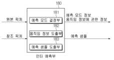
도 10은 일 실시예에 따른 인터 예측부(180)의 구성을 예시적으로 도시한 도면이다.
도 11은 일 실시예에 따른 인터 예측 기반 비디오/영상 디코딩 방법을 도시한 흐름도이다.
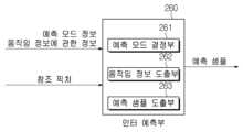
도 12는 일 실시예에 따른 인터 예측부(260)의 구성을 예시적으로 도시한 도면이다.
도 13은 일 실시예에 따른 공간적 머지 후보로 이용될 수 있는 주변 블록들을 예시한 도면이다.
도 14는 일 실시예에 따른 머지 후보 리스트 구성 방법을 개략적으로 나타낸 도면이다.
도 15는 일 실시예에 따른 움직임 벡터 예측자 후보 리스트 구성 방법을 개략적으로 나타낸 도면이다.
도 16은 일 실시예에 따른 영상 부호화 장치로부터 영상 복호화 장치로 MVD를 전송하기 위한 신택스 구조를 도시한 도면이다.
도 17은 일 실시예에 따른 IBC 기반 비디오/영상 인코딩 방법을 도시한 흐름도이다.
도 18은 일 실시예에 따른 IBC 기반 비디오/영상 인코딩 방법을 수행하는 예측부의 구성을 예시적으로 도시한 도면이다.
도 19는 일 실시예에 따른 IBC 기반 비디오/영상 디코딩 방법을 도시한 흐름도이다.
도 20은 일 실시예에 따른 IBC 기반 비디오/영상 디코딩 방법을 수행하는 예측부의 구성을 예시적으로 도시한 도면이다.
도 21은 일 실시 예에 따른 크로마 포멧 시그널링을 위한 신택스를 도시하는 도면이다.
도 22는 일 실시 예에 따른 크로마 포멧 분류 표를 도시하는 도면이다.
도 23은 가상 파이프라인 처리를 위한 CU의 분할 제한 사례를 설명하는 도면이다.
도 24 내지 도 26은 일 실시 예에 따른 CU와 TU의 분할 사례를 도시하는 도면이다.
도 27 및 도 28은 일 실시 예에 따른 최대 변환 크기가 적용된 인터 예측 및 인트라 예측을 나타내는 순서도이다.
도 29는 일 실시 예에 따른 부호화 장치가 영상을 부호화하는 방법을 설명하는 순서도이다.
도 30은 일 실시 예에 따른 복호화 장치가 영상을 복호화하는 방법을 설명하는 순서도이다.
도 31은 본 개시의 실시예가 적용될 수 있는 컨텐츠 스트리밍 시스템을 예시한 도면이다.FIG. 1 is a diagram schematically illustrating a video coding system to which an embodiment according to the present disclosure can be applied.
FIG. 2 is a diagram schematically illustrating an image encoding device to which an embodiment according to the present disclosure can be applied.
FIG. 3 is a diagram schematically illustrating an image decoding device to which an embodiment according to the present disclosure can be applied.
FIG. 4 is a diagram showing an image segmentation structure according to one embodiment.
FIG. 5 is a diagram illustrating one embodiment of a block division type according to a multi-type tree structure.
FIG. 6 is a diagram illustrating a signaling mechanism of block partition information in a quadtree with nested multi-type tree structure according to the present disclosure.
FIG. 7 is a diagram illustrating an embodiment in which a CTU is divided into multiple CUs.
FIG. 8 is a diagram illustrating one embodiment of a redundant partition pattern.
FIG. 9 is a flowchart illustrating an inter-prediction based video/image encoding method according to one embodiment.
FIG. 10 is a diagram exemplarily illustrating the configuration of an inter prediction unit (180) according to one embodiment.
FIG. 11 is a flowchart illustrating an inter-prediction based video/image decoding method according to one embodiment.
FIG. 12 is a diagram exemplarily illustrating the configuration of an inter prediction unit (260) according to one embodiment.
FIG. 13 is a diagram illustrating surrounding blocks that can be used as spatial merge candidates according to one embodiment.
FIG. 14 is a diagram schematically illustrating a method for constructing a merge candidate list according to one embodiment.
FIG. 15 is a diagram schematically illustrating a method for constructing a motion vector predictor candidate list according to one embodiment.
FIG. 16 is a diagram illustrating a syntax structure for transmitting an MVD from an image encoding device to an image decoding device according to one embodiment.
FIG. 17 is a flowchart illustrating an IBC-based video/image encoding method according to one embodiment.
FIG. 18 is a diagram exemplarily illustrating the configuration of a prediction unit that performs an IBC-based video/image encoding method according to one embodiment.
FIG. 19 is a flowchart illustrating an IBC-based video/image decoding method according to one embodiment.
FIG. 20 is a diagram exemplarily illustrating the configuration of a prediction unit that performs an IBC-based video/image decoding method according to one embodiment.
FIG. 21 is a diagram illustrating syntax for chroma format signaling according to one embodiment.
FIG. 22 is a diagram illustrating a chroma format classification table according to one embodiment.
Figure 23 is a diagram illustrating a case of limiting the partitioning of CUs for virtual pipeline processing.
FIGS. 24 to 26 are diagrams illustrating division cases of CUs and TUs according to one embodiment.
FIG. 27 and FIG. 28 are flowcharts illustrating inter prediction and intra prediction with maximum transformation size applied according to one embodiment.
FIG. 29 is a flowchart illustrating a method for encoding an image by an encoding device according to one embodiment.
FIG. 30 is a flowchart illustrating a method for a decryption device to decrypt an image according to one embodiment.
FIG. 31 is a diagram illustrating a content streaming system to which an embodiment of the present disclosure can be applied.
이하에서는 첨부한 도면을 참고로 하여 본 개시의 실시예에 대하여 본 개시가 속하는 기술 분야에서 통상의 지식을 가진 자가 용이하게 실시할 수 있도록 상세히 설명한다. 그러나, 본 개시는 여러 가지 상이한 형태로 구현될 수 있으며 여기에서 설명하는 실시예에 한정되지 않는다.Hereinafter, embodiments of the present disclosure will be described in detail with reference to the attached drawings so that those skilled in the art can easily implement the present disclosure. However, the present disclosure may be implemented in various different forms and is not limited to the embodiments described herein.
본 개시의 실시예를 설명함에 있어서 공지 구성 또는 기능에 대한 구체적인 설명이 본 개시의 요지를 흐릴 수 있다고 판단되는 경우에는 그에 대한 상세한 설명은 생략한다. 그리고, 도면에서 본 개시에 대한 설명과 관계없는 부분은 생략하였으며, 유사한 부분에 대해서는 유사한 도면 부호를 붙였다.In describing embodiments of the present disclosure, if it is determined that a detailed description of a known configuration or function may obscure the gist of the present disclosure, a detailed description thereof will be omitted. In addition, parts in the drawings that are not related to the description of the present disclosure have been omitted, and similar parts have been given similar drawing reference numerals.
본 개시에 있어서, 어떤 구성요소가 다른 구성요소와 "연결", "결합" 또는 "접속"되어 있다고 할 때, 이는 직접적인 연결관계뿐만 아니라, 그 중간에 또 다른 구성요소가 존재하는 간접적인 연결관계도 포함할 수 있다. 또한 어떤 구성요소가 다른 구성요소를 "포함한다" 또는 "가진다"고 할 때, 이는 특별히 반대되는 기재가 없는 한 다른 구성요소를 배제하는 것이 아니라 또 다른 구성요소를 더 포함할 수 있는 것을 의미한다.In the present disclosure, when a component is said to be "connected," "coupled," or "connected" to another component, this may include not only a direct connection relationship, but also an indirect connection relationship in which another component exists in between. In addition, when a component is said to "include" or "have" another component, this does not exclude the other component unless specifically stated otherwise, but means that the other component may be included.
본 개시에 있어서, 제1, 제2 등의 용어는 하나의 구성요소를 다른 구성요소로부터 구별하는 목적으로만 사용되며, 특별히 언급되지 않는 한 구성요소들간의 순서 또는 중요도 등을 한정하지 않는다. 따라서, 본 개시의 범위 내에서 일 실시예에서의 제1 구성요소는 다른 실시예에서 제2 구성요소라고 칭할 수도 있고, 마찬가지로 일 실시예에서의 제2 구성요소를 다른 실시예에서 제1 구성요소라고 칭할 수도 있다.In this disclosure, the terms first, second, etc. are used only for the purpose of distinguishing one component from another component, and do not limit the order or importance between the components unless specifically stated otherwise. Accordingly, within the scope of this disclosure, a first component in one embodiment may be referred to as a second component in another embodiment, and similarly, a second component in one embodiment may be referred to as a first component in another embodiment.
본 개시에 있어서, 서로 구별되는 구성요소들은 각각의 특징을 명확하게 설명하기 위함이며, 구성요소들이 반드시 분리되는 것을 의미하지는 않는다. 즉, 복수의 구성요소가 통합되어 하나의 하드웨어 또는 소프트웨어 단위로 이루어질 수도 있고, 하나의 구성요소가 분산되어 복수의 하드웨어 또는 소프트웨어 단위로 이루어질 수도 있다. 따라서, 별도로 언급하지 않더라도 이와 같이 통합된 또는 분산된 실시예도 본 개시의 범위에 포함된다.In the present disclosure, the components that are distinguished from each other are intended to clearly explain the characteristics of each, and do not necessarily mean that the components are separated. That is, a plurality of components may be integrated to form a single hardware or software unit, or a single component may be distributed to form a plurality of hardware or software units. Accordingly, even if not mentioned separately, such integrated or distributed embodiments are also included in the scope of the present disclosure.
본 개시에 있어서, 다양한 실시예에서 설명하는 구성요소들이 반드시 필수적인 구성요소들을 의미하는 것은 아니며, 일부는 선택적인 구성요소일 수 있다. 따라서, 일 실시예에서 설명하는 구성요소들의 부분집합으로 구성되는 실시예도 본 개시의 범위에 포함된다. 또한, 다양한 실시예에서 설명하는 구성요소들에 추가적으로 다른 구성요소를 포함하는 실시예도 본 개시의 범위에 포함된다.In the present disclosure, the components described in various embodiments do not necessarily mean essential components, and some may be optional components. Accordingly, an embodiment that consists of a subset of the components described in one embodiment is also included in the scope of the present disclosure. In addition, an embodiment that includes other components in addition to the components described in various embodiments is also included in the scope of the present disclosure.
본 개시는 영상의 부호화 및 복호화에 관한 것으로서, 본 개시에서 사용되는 용어는, 본 개시에서 새롭게 정의되지 않는 한 본 개시가 속한 기술 분야에서 통용되는 통상의 의미를 가질 수 있다.The present disclosure relates to encoding and decoding of images, and terms used in the present disclosure may have their usual meanings used in the technical field to which the present disclosure belongs, unless newly defined in the present disclosure.
본 개시에서 "픽처(picture)"는 일반적으로 특정 시간대의 하나의 영상을 나타내는 단위를 의미하며, 슬라이스(slice)/타일(tile)은 픽처의 일부를 구성하는 부호화 단위로서, 하나의 픽처는 하나 이상의 슬라이스/타일로 구성될 수 있다. 또한, 슬라이스/타일은 하나 이상의 CTU(coding tree unit)를 포함할 수 있다.In the present disclosure, a "picture" generally means a unit representing one image of a specific time period, and a slice/tile is a coding unit constituting a part of a picture, and one picture may be composed of one or more slices/tiles. In addition, a slice/tile may include one or more CTUs (coding tree units).
본 개시에서 "픽셀(pixel)" 또는 "펠(pel)"은 하나의 픽처(또는 영상)를 구성하는 최소의 단위를 의미할 수 있다. 또한, 픽셀에 대응하는 용어로서 "샘플(sample)"이 사용될 수 있다. 샘플은 일반적으로 픽셀 또는 픽셀의 값을 나타낼 수 있으며, 루마(luma) 성분의 픽셀/픽셀값만을 나타낼 수도 있고, 크로마(chroma) 성분의 픽셀/픽셀 값만을 나타낼 수도 있다.In the present disclosure, "pixel" or "pel" may mean the smallest unit that constitutes a picture (or image). In addition, "sample" may be used as a term corresponding to a pixel. A sample may generally represent a pixel or a pixel value, and may represent only a pixel/pixel value of a luma component, or only a pixel/pixel value of a chroma component.
본 개시에서 "유닛(unit)"은 영상 처리의 기본 단위를 나타낼 수 있다. 유닛은 픽처의 특정 영역 및 해당 영역에 관련된 정보 중 적어도 하나를 포함할 수 있다. 유닛은 경우에 따라서 "샘플 어레이", "블록(block)" 또는 "영역(area)" 등의 용어와 혼용하여 사용될 수 있다. 일반적인 경우, MxN 블록은 M개의 열과 N개의 행으로 이루어진 샘플들(또는 샘플 어레이) 또는 변환 계수(transform coefficient)들의 집합(또는 어레이)을 포함할 수 있다.In the present disclosure, a "unit" may represent a basic unit of image processing. A unit may include at least one of a specific region of a picture and information related to the region. The unit may be used interchangeably with terms such as "sample array", "block" or "area" as the case may be. In general, an MxN block may include a set (or array) of samples (or sample array) or transform coefficients consisting of M columns and N rows.
본 개시에서 "현재 블록"은 "현재 코딩 블록", "현재 코딩 유닛", "부호화 대상 블록", "복호화 대상 블록" 또는 "처리 대상 블록" 중 하나를 의미할 수 있다. 예측이 수행되는 경우, "현재 블록"은 "현재 예측 블록" 또는 "예측 대상 블록"을 의미할 수 있다. 변환(역변환)/양자화(역양자화)가 수행되는 경우, "현재 블록"은 "현재 변환 블록" 또는 "변환 대상 블록"을 의미할 수 있다. 필터링이 수행되는 경우, "현재 블록"은 "필터링 대상 블록"을 의미할 수 있다.In the present disclosure, the "current block" may mean one of the "current coding block", the "current coding unit", the "encoding target block", the "decoding target block" or the "processing target block". When prediction is performed, the "current block" may mean the "current prediction block" or the "prediction target block". When transformation (inverse transformation)/quantization (inverse quantization) is performed, the "current block" may mean the "current transformation block" or the "transformation target block". When filtering is performed, the "current block" may mean the "filtering target block".
또한, 본 개시에서 "현재 블록"은 크로마 블록이라는 명시적인 기재가 없는 한 "현재 블록의 루마 블록"을 의미할 수 있다. "현재 블록의 크로마 블록"은 명시적으로 "크로마 블록" 또는 "현재 크로마 블록"과 같이 크로마 블록이라는 명시적인 기재를 포함하여 표현될 수 있다.Additionally, in the present disclosure, the "current block" may mean the "luma block of the current block" unless there is an explicit description that it is a chroma block. The "chroma block of the current block" may be expressed by including an explicit description that it is a chroma block, such as "chroma block" or "current chroma block".
본 개시에서 "/"와 ","는 "및/또는"으로 해석될 수 있다. 예를 들어, "A/B"와 "A, B"는 "A 및/또는 B"로 해석될 수 있다. 또한, "A/B/C"와 "A, B, C"는 "A, B 및/또는 C 중 적어도 하나"를 의미할 수 있다.In this disclosure, "/" and "," can be interpreted as "and/or". For example, "A/B" and "A, B" can be interpreted as "A and/or B". Additionally, "A/B/C" and "A, B, C" can mean "at least one of A, B, and/or C".
본 개시에서 "또는"은 "및/또는"으로 해석될 수 있다. 예를 들어, "A 또는 B"는, 1) "A" 만을 의미하거나 2) "B" 만을 의미하거나, 3) "A 및 B"를 의미할 수 있다. 또는, 본 개시에서 "또는"은 "추가적으로 또는 대체적으로(additionally or alternatively)"를 의미할 수 있다.In this disclosure, "or" can be interpreted as "and/or." For example, "A or B" can mean 1) "A" only, 2) "B" only, or 3) "A and B." Alternatively, "or" in this disclosure can mean "additionally or alternatively."
비디오 코딩 시스템 개요Overview of Video Coding Systems
도 1은 본 개시에 따른 비디오 코딩 시스템을 도시한다.FIG. 1 illustrates a video coding system according to the present disclosure.
일 실시예에 따른 비디오 코딩 시스템은 부호화 장치(10) 및 복호화 장치(20)를 포함할 수 있다. 부호화 장치(10)는 부호화된 비디오(video) 및/또는 영상(image) 정보 또는 데이터를 파일 또는 스트리밍 형태로 디지털 저장매체 또는 네트워크를 통하여 복호화 장치(20)로 전달할 수 있다.A video coding system according to one embodiment may include an encoding device (10) and a decoding device (20). The encoding device (10) may transmit encoded video and/or image information or data to the decoding device (20) in the form of a file or streaming through a digital storage medium or a network.
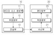
일 실시예예 따른 부호화 장치(10)는 비디오 소스 생성부(11), 부호화부(12), 전송부(13)를 포함할 수 있다. 일 실시예에 따른 복호화 장치(20)는 수신부(21), 복호화부(22) 및 렌더링부(23)를 포함할 수 있다. 상기 부호화부(12)는 비디오/영상 부호화부라고 불릴 수 있고, 상기 복호화부(22)는 비디오/영상 복호화부라고 불릴 수 있다. 전송부(13)는 부호화부(12)에 포함될 수 있다. 수신부(21)는 복호화부(22)에 포함될 수 있다. 렌더링부(23)는 디스플레이부를 포함할 수도 있고, 디스플레이부는 별개의 디바이스 또는 외부 컴포넌트로 구성될 수도 있다.An encoding device (10) according to an embodiment may include a video source generating unit (11), an encoding unit (12), and a transmitting unit (13). A decoding device (20) according to an embodiment may include a receiving unit (21), a decoding unit (22), and a rendering unit (23). The encoding unit (12) may be called a video/image encoding unit, and the decoding unit (22) may be called a video/image decoding unit. The transmitting unit (13) may be included in the encoding unit (12). The receiving unit (21) may be included in the decoding unit (22). The rendering unit (23) may include a display unit, and the display unit may be configured as a separate device or an external component.
비디오 소스 생성부(11)는 비디오/영상의 캡쳐, 합성 또는 생성 과정 등을 통하여 비디오/영상을 획득할 수 있다. 비디오 소스 생성부(11)는 비디오/영상 캡쳐 디바이스 및/또는 비디오/영상 생성 디바이스를 포함할 수 있다. 비디오/영상 캡쳐 디바이스는 예를 들어, 하나 이상의 카메라, 이전에 캡쳐된 비디오/영상을 포함하는 비디오/영상 아카이브 등을 포함할 수 있다. 비디오/영상 생성 디바이스는 예를 들어 컴퓨터, 타블렛 및 스마트폰 등을 포함할 수 있으며 (전자적으로) 비디오/영상을 생성할 수 있다. 예를 들어, 컴퓨터 등을 통하여 가상의 비디오/영상이 생성될 수 있으며, 이 경우 관련 데이터가 생성되는 과정으로 비디오/영상 캡쳐 과정이 갈음될 수 있다.The video source generation unit (11) can obtain a video/image through a process of capturing, synthesizing, or generating a video/image. The video source generation unit (11) can include a video/image capture device and/or a video/image generation device. The video/image capture device can include, for example, one or more cameras, a video/image archive including previously captured video/image, etc. The video/image generation device can include, for example, a computer, a tablet, a smartphone, etc., and can (electronically) generate a video/image. For example, a virtual video/image can be generated through a computer, etc., and in this case, the video/image capture process can be replaced with a process of generating related data.
부호화부(12)는 입력 비디오/영상을 부호화할 수 있다. 부호화부(12)는 압축 및 부호화 효율을 위하여 예측, 변환, 양자화 등 일련의 절차를 수행할 수 있다. 부호화부(12)는 부호화된 데이터(부호화된 비디오/영상 정보)를 비트스트림(bitstream) 형태로 출력할 수 있다.The encoding unit (12) can encode input video/image. The encoding unit (12) can perform a series of procedures such as prediction, transformation, and quantization for compression and encoding efficiency. The encoding unit (12) can output encoded data (encoded video/image information) in the form of a bitstream.
전송부(13)는 비트스트림 형태로 출력된 부호화된 비디오/영상 정보 또는 데이터를 파일 또는 스트리밍 형태로 디지털 저장매체 또는 네트워크를 통하여 복호화 장치(20)의 수신부(21)로 전달할 수 있다. 디지털 저장 매체는 USB, SD, CD, DVD, 블루레이, HDD, SSD 등 다양한 저장 매체를 포함할 수 있다. 전송부(13)는 미리 정해진 파일 포멧을 통하여 미디어 파일을 생성하기 위한 엘리먼트를 포함할 수 있고, 방송/통신 네트워크를 통한 전송을 위한 엘리먼트를 포함할 수 있다. 수신부(21)는 상기 저장매체 또는 네트워크로부터 상기 비트스트림을 추출/수신하여 복호화부(22)로 전달할 수 있다.The transmission unit (13) can transmit encoded video/image information or data output in the form of a bitstream to the reception unit (21) of the decoding device (20) through a digital storage medium or a network in the form of a file or streaming. The digital storage medium can include various storage media such as USB, SD, CD, DVD, Blu-ray, HDD, SSD, etc. The transmission unit (13) can include an element for generating a media file through a predetermined file format and can include an element for transmission through a broadcasting/communication network. The reception unit (21) can extract/receive the bitstream from the storage medium or network and transmit it to the decoding unit (22).
복호화부(22)는 부호화부(12)의 동작에 대응하는 역양자화, 역변환, 예측 등 일련의 절차를 수행하여 비디오/영상을 복호화할 수 있다.The decoding unit (22) can decode video/image by performing a series of procedures such as inverse quantization, inverse transformation, and prediction corresponding to the operation of the encoding unit (12).
렌더링부(23)는 복호화된 비디오/영상을 렌더링할 수 있다. 렌더링된 비디오/영상은 디스플레이부를 통하여 디스플레이될 수 있다.The rendering unit (23) can render the decrypted video/image. The rendered video/image can be displayed through the display unit.
영상 부호화 장치 개요Overview of the video encoding device
도 2는 본 개시에 따른 실시예가 적용될 수 있는 영상 부호화 장치를 개략적으로 도시한 도면이다.FIG. 2 is a diagram schematically illustrating an image encoding device to which an embodiment according to the present disclosure can be applied.
도 2에 도시된 바와 같이, 영상 부호화 장치(100)는 영상 분할부(110), 감산부(115), 변환부(120), 양자화부(130), 역양자화부(140), 역변환부(150), 가산부(155), 필터링부(160), 메모리(170), 인터 예측부(180), 인트라 예측부(185) 및 엔트로피 인코딩부(190)를 포함할 수 있다. 인터 예측부(180) 및 인트라 예측부(185)는 합쳐서 "예측부"라고 지칭될 수 있다. 변환부(120), 양자화부(130), 역양자화부(140), 역변환부(150)는 레지듀얼(residual) 처리부에 포함될 수 있다. 레지듀얼 처리부는 감산부(115)를 더 포함할 수도 있다.As illustrated in FIG. 2, the image encoding device (100) may include an image segmentation unit (110), a subtraction unit (115), a transformation unit (120), a quantization unit (130), an inverse quantization unit (140), an inverse transformation unit (150), an addition unit (155), a filtering unit (160), a memory (170), an inter prediction unit (180), an intra prediction unit (185), and an entropy encoding unit (190). The inter prediction unit (180) and the intra prediction unit (185) may be collectively referred to as a “prediction unit.” The transformation unit (120), the quantization unit (130), the inverse quantization unit (140), and the inverse transformation unit (150) may be included in a residual processing unit. The residual processing unit may further include a subtraction unit (115).
영상 부호화 장치(100)를 구성하는 복수의 구성부들의 전부 또는 적어도 일부는 실시예에 따라 하나의 하드웨어 컴포넌트(예를 들어, 인코더 또는 프로세서)로 구현될 수 있다. 또한 메모리(170)는 DPB(decoded picture buffer)를 포함할 수 있고, 디지털 저장 매체에 의하여 구현될 수 있다.All or at least some of the plurality of components constituting the video encoding device (100) may be implemented as a single hardware component (e.g., an encoder or a processor) according to an embodiment. In addition, the memory (170) may include a DPB (decoded picture buffer) and may be implemented by a digital storage medium.
영상 분할부(110)는 영상 부호화 장치(100)에 입력된 입력 영상(또는, 픽쳐, 프레임)을 하나 이상의 처리 유닛(processing unit)으로 분할할 수 있다. 일 예로, 상기 처리 유닛은 코딩 유닛(coding unit, CU)이라고 불릴 수 있다. 코딩 유닛은 코딩 트리 유닛(coding tree unit, CTU) 또는 최대 코딩 유닛(largest coding unit, LCU)을 QT/BT/TT (Quad-tree/binary-tree/ternary-tree) 구조에 따라 재귀적으로(recursively) 분할함으로써 획득될 수 있다. 예를 들어, 하나의 코딩 유닛은 쿼드 트리 구조, 바이너리 트리 구조 및/또는 터너리 트리 구조를 기반으로 하위(deeper) 뎁스의 복수의 코딩 유닛들로 분할될 수 있다. 코딩 유닛의 분할을 위해, 쿼드 트리 구조가 먼저 적용되고 바이너리 트리 구조 및/또는 터너리 트리 구조가 나중에 적용될 수 있다. 더 이상 분할되지 않는 최종 코딩 유닛을 기반으로 본 개시에 따른 코딩 절차가 수행될 수 있다. 최대 코딩 유닛이 바로 최종 코딩 유닛으로 사용될 수 있고, 최대 코딩 유닛을 분할하여 획득한 하위 뎁스의 코딩 유닛이 최종 코닛 유닛으로 사용될 수도 있다. 여기서 코딩 절차라 함은 후술하는 예측, 변환 및/또는 복원 등의 절차를 포함할 수 있다. 다른 예로, 상기 코딩 절차의 처리 유닛은 예측 유닛(PU: Prediction Unit) 또는 변환 유닛(TU: Transform Unit)일 수 있다. 상기 예측 유닛 및 상기 변환 유닛은 각각 상기 최종 코딩 유닛으로부터 분할 또는 파티셔닝될 수 있다. 상기 예측 유닛은 샘플 예측의 단위일 수 있고, 상기 변환 유닛은 변환 계수를 유도하는 단위 및/또는 변환 계수로부터 레지듀얼 신호(residual signal)를 유도하는 단위일 수 있다.The image segmentation unit (110) can segment an input image (or, picture, frame) input to the image encoding device (100) into one or more processing units. For example, the processing unit may be called a coding unit (CU). The coding unit may be obtained by recursively segmenting a coding tree unit (CTU) or a largest coding unit (LCU) according to a QT/BT/TT (Quad-tree/binary-tree/ternary-tree) structure. For example, one coding unit may be segmented into a plurality of coding units of deeper depth based on a quad-tree structure, a binary-tree structure, and/or a ternary-tree structure. For segmenting the coding unit, the quad-tree structure may be applied first, and the binary-tree structure and/or the ternary-tree structure may be applied later. The coding procedure according to the present disclosure may be performed based on a final coding unit that is no longer segmented. The maximum coding unit can be used as the final coding unit, and the coding unit of the lower depth obtained by dividing the maximum coding unit can be used as the final concatenated unit. Here, the coding procedure can include procedures such as prediction, transformation, and/or restoration described below. As another example, the processing unit of the coding procedure can be a prediction unit (PU) or a transform unit (TU). The prediction unit and the transform unit can be divided or partitioned from the final coding unit, respectively. The prediction unit can be a unit of sample prediction, and the transform unit can be a unit for deriving a transform coefficient and/or a unit for deriving a residual signal from a transform coefficient.
예측부(인터 예측부(180) 또는 인트라 예측부(185))는 처리 대상 블록(현재 블록)에 대한 예측을 수행하고, 상기 현재 블록에 대한 예측 샘플들을 포함하는 예측된 블록(predicted block)을 생성할 수 있다. 예측부는 현재 블록 또는 CU 단위로 인트라 예측이 적용되는지 또는 인터 예측이 적용되는지 결정할 수 있다. 예측부는 현재 블록의 예측에 관한 다양한 정보를 생성하여 엔트로피 인코딩부(190)로 전달할 수 있다. 예측에 관한 정보는 엔트로피 인코딩부(190)에서 인코딩되어 비트스트림 형태로 출력될 수 있다.The prediction unit (inter prediction unit (180) or intra prediction unit (185)) can perform prediction on a block to be processed (current block) and generate a predicted block including prediction samples for the current block. The prediction unit can determine whether intra prediction or inter prediction is applied to the current block or CU unit. The prediction unit can generate various information about the prediction of the current block and transfer it to the entropy encoding unit (190). The information about the prediction can be encoded by the entropy encoding unit (190) and output in the form of a bitstream.
인트라 예측부(185)는 현재 픽처 내의 샘플들을 참조하여 현재 블록을 예측할 수 있다. 상기 참조되는 샘플들은 인트라 예측 모드 및/또는 인트라 예측 기법에 따라 상기 현재 블록의 주변(neighbor)에 위치할 수 있고, 또는 떨어져서 위치할 수도 있다. 인트라 예측 모드들은 복수의 비방향성 모드와 복수의 방향성 모드를 포함할 수 있다. 비방향성 모드는 예를 들어 DC 모드 및 플래너 모드(Planar 모드)를 포함할 수 있다. 방향성 모드는 예측 방향의 세밀한 정도에 따라, 예를 들어 33개의 방향성 예측 모드 또는 65개의 방향성 예측 모드를 포함할 수 있다. 다만, 이는 예시로서 설정에 따라 그 이상 또는 그 이하의 개수의 방향성 예측 모드들이 사용될 수 있다. 인트라 예측부(185)는 주변 블록에 적용된 예측 모드를 이용하여, 현재 블록에 적용되는 예측 모드를 결정할 수도 있다.The intra prediction unit (185) can predict the current block by referring to samples in the current picture. The referenced samples may be located in the neighborhood of the current block or may be located away from it depending on the intra prediction mode and/or the intra prediction technique. The intra prediction modes may include a plurality of non-directional modes and a plurality of directional modes. The non-directional mode may include, for example, a DC mode and a planar mode. The directional mode may include, for example, 33 directional prediction modes or 65 directional prediction modes depending on the degree of detail of the prediction direction. However, this is only an example, and a number of directional prediction modes greater or less than that may be used depending on the setting. The intra prediction unit (185) may also determine the prediction mode applied to the current block by using the prediction mode applied to the neighboring block.
인터 예측부(180)는 참조 픽처 상에서 움직임 벡터에 의해 특정되는 참조 블록(참조 샘플 어레이)을 기반으로, 현재 블록에 대한 예측된 블록을 유도할 수 있다. 이때, 인터 예측 모드에서 전송되는 움직임 정보의 양을 줄이기 위해 주변 블록과 현재 블록 간의 움직임 정보의 상관성에 기반하여 움직임 정보를 블록, 서브블록 또는 샘플 단위로 예측할 수 있다. 상기 움직임 정보는 움직임 벡터 및 참조 픽처 인덱스를 포함할 수 있다. 상기 움직임 정보는 인터 예측 방향(L0 예측, L1 예측, Bi 예측 등) 정보를 더 포함할 수 있다. 인터 예측의 경우, 주변 블록은 현재 픽처 내에 존재하는 공간적 주변 블록(spatial neighboring block)과 참조 픽처에 존재하는 시간적 주변 블록(temporal neighboring block)을 포함할 수 있다. 상기 참조 블록을 포함하는 참조 픽처와 상기 시간적 주변 블록을 포함하는 참조 픽처는 동일할 수도 있고, 서로 다를 수도 있다. 상기 시간적 주변 블록은 동일 위치 참조 블록(collocated reference block), 동일 위치 CU(colCU) 등의 이름으로 불릴 수 있다. 상기 시간적 주변 블록을 포함하는 참조 픽처는 동일 위치 픽처(collocated picture, colPic)라고 불릴 수 있다. 예를 들어, 인터 예측부(180)는 주변 블록들을 기반으로 움직임 정보 후보 리스트를 구성하고, 상기 현재 블록의 움직임 벡터 및/또는 참조 픽처 인덱스를 도출하기 위하여 어떤 후보가 사용되는지를 지시하는 정보를 생성할 수 있다. 다양한 예측 모드를 기반으로 인터 예측이 수행될 수 있으며, 예를 들어 스킵 모드와 머지 모드의 경우에, 인터 예측부(180)는 주변 블록의 움직임 정보를 현재 블록의 움직임 정보로 이용할 수 있다. 스킵 모드의 경우, 머지 모드와 달리 레지듀얼 신호가 전송되지 않을 수 있다. 움직임 정보 예측(motion vector prediction, MVP) 모드의 경우, 주변 블록의 움직임 벡터를 움직임 벡터 예측자(motion vector predictor)로 이용하고, 움직임 벡터 차분(motion vector difference) 및 움직임 벡터 예측자에 대한 지시자(indicator)를 부호화함으로써 현재 블록의 움직임 벡터를 시그널링할 수 있다. 움직임 벡터 차분은 현재 블록의 움직임 벡터와 움직임 벡터 예측자 간의 차이를 의미할 수 있다.The inter prediction unit (180) can derive a predicted block for a current block based on a reference block (reference sample array) specified by a motion vector on a reference picture. At this time, in order to reduce the amount of motion information transmitted in the inter prediction mode, the motion information can be predicted in units of blocks, subblocks, or samples based on the correlation of motion information between neighboring blocks and the current block. The motion information can include a motion vector and a reference picture index. The motion information can further include information on an inter prediction direction (such as L0 prediction, L1 prediction, or Bi prediction). In the case of inter prediction, neighboring blocks can include spatial neighboring blocks existing in the current picture and temporal neighboring blocks existing in the reference picture. The reference picture including the reference block and the reference picture including the temporal neighboring block may be the same or different from each other. The temporal neighboring blocks may be called collocated reference blocks, collocated CUs (colCUs), etc. The reference picture including the above temporal neighboring blocks may be called a collocated picture (colPic). For example, the inter prediction unit (180) may construct a motion information candidate list based on the neighboring blocks, and generate information indicating which candidate is used to derive the motion vector and/or reference picture index of the current block. Inter prediction may be performed based on various prediction modes, and for example, in the case of the skip mode and the merge mode, the inter prediction unit (180) may use the motion information of the neighboring blocks as the motion information of the current block. In the case of the skip mode, unlike the merge mode, a residual signal may not be transmitted. In the case of the motion vector prediction (MVP) mode, the motion vector of the current block may be signaled by using the motion vector of the neighboring blocks as a motion vector predictor, and encoding an indicator for the motion vector difference and the motion vector predictor. Motion vector difference can mean the difference between the motion vector of the current block and the motion vector predictor.
예측부는 후술하는 다양한 예측 방법 및/또는 예측 기법을 기반으로 예측 신호를 생성할 수 있다. 예를 들어, 예측부는 현재 블록의 예측을 위해 인트라 예측 또는 인터 예측을 적용할 수 있을 뿐 아니라, 인트라 예측과 인터 예측을 동시에 적용할 수 있다. 현재 블록의 예측을 위해 인트라 예측과 인터 예측을 동시에 적용하는 예측 방법은 combined inter and intra prediction (CIIP)라고 불릴 수 있다. 또한, 예측부는 현재 블록의 예측을 위해 인트라 블록 카피(intra block copy, IBC)를 수행할 수도 있다. 인트라 블록 카피는 예를 들어 SCC(screen content coding) 등과 같이 게임 등의 컨텐츠 영상/동영상 코딩을 위하여 사용될 수 있다. IBC는 현재 블록으로부터 소정의 거리만큼 떨어진 위치의 현재 픽처 내 기복원된 참조 블록을 이용하여 현재 블록을 예측하는 방법이다. IBC가 적용되는 경우, 현재 픽처 내 참조 블록의 위치는 상기 소정의 거리에 해당하는 벡터(블록 벡터)로서 부호화될 수 있다. IBC는 기본적으로 현재 픽처 내에서 예측을 수행하나, 현재 픽처 내에서 참조 블록을 도출하는 점에서, 인터 예측과 유사하게 수행될 수 있다. 즉 IBC는 본 개시에서 설명되는 인터 예측 기법들 중 적어도 하나를 이용할 수 있다.The prediction unit can generate a prediction signal based on various prediction methods and/or prediction techniques described below. For example, the prediction unit can apply intra prediction or inter prediction for prediction of the current block, and can also apply intra prediction and inter prediction at the same time. A prediction method that applies intra prediction and inter prediction at the same time for prediction of the current block can be called combined inter and intra prediction (CIIP). In addition, the prediction unit can perform intra block copy (IBC) for prediction of the current block. Intra block copy can be used for content image/video coding such as games, such as screen content coding (SCC). IBC is a method of predicting the current block using a restored reference block in the current picture at a location a predetermined distance away from the current block. When IBC is applied, the location of the reference block in the current picture can be encoded as a vector (block vector) corresponding to the predetermined distance. IBC basically performs prediction within the current picture, but can be performed similarly to inter prediction in that it derives reference blocks within the current picture. That is, IBC can utilize at least one of the inter prediction techniques described in the present disclosure.
예측부를 통해 생성된 예측 신호는 복원 신호를 생성하기 위해 이용되거나 레지듀얼 신호를 생성하기 위해 이용될 수 있다. 감산부(115)는 입력 영상 신호(원본 블록, 원본 샘플 어레이)로부터 예측부에서 출력된 예측 신호(예측된 블록, 예측 샘플 어레이)를 감산하여 레지듀얼 신호(residual signal, 잔여 블록, 잔여 샘플 어레이)를 생성할 수 있다. 생성된 레지듀얼 신호는 변환부(120)로 전송될 수 있다.The prediction signal generated through the prediction unit can be used to generate a restoration signal or to generate a residual signal. The subtraction unit (115) can generate a residual signal (residual block, residual sample array) by subtracting the prediction signal (predicted block, predicted sample array) output from the prediction unit from the input image signal (original block, original sample array). The generated residual signal can be transmitted to the conversion unit (120).
변환부(120)는 레지듀얼 신호에 변환 기법을 적용하여 변환 계수들(transform coefficients)을 생성할 수 있다. 예를 들어, 변환 기법은 DCT(Discrete Cosine Transform), DST(Discrete Sine Transform), KLT(Karhunen-Loeve Transform), GBT(Graph-Based Transform), 또는 CNT(Conditionally Non-linear Transform) 중 적어도 하나를 포함할 수 있다. 여기서, GBT는 픽셀 간의 관계 정보를 그래프로 표현한다고 할 때 이 그래프로부터 얻어진 변환을 의미한다. CNT는 이전에 복원된 모든 픽셀(all previously reconstructed pixel)을 이용하여 예측 신호를 생성하고 그에 기반하여 획득되는 변환을 의미한다. 변환 과정은 정사각형의 동일한 크기를 갖는 픽셀 블록에 적용될 수도 있고, 정사각형이 아닌 가변 크기의 블록에도 적용될 수 있다.The transform unit (120) can apply a transform technique to the residual signal to generate transform coefficients. For example, the transform technique can include at least one of a Discrete Cosine Transform (DCT), a Discrete Sine Transform (DST), a Karhunen-Loeve Transform (KLT), a Graph-Based Transform (GBT), or a Conditionally Non-linear Transform (CNT). Here, GBT means a transform obtained from a graph when the relationship information between pixels is expressed as a graph. CNT means a transform obtained based on generating a prediction signal using all previously reconstructed pixels. The transform process can be applied to a pixel block having a square equal size, or can be applied to a block of a non-square variable size.
양자화부(130)는 변환 계수들을 양자화하여 엔트로피 인코딩부(190)로 전송할 수 있다. 엔트로피 인코딩부(190)는 양자화된 신호(양자화된 변환 계수들에 관한 정보)를 인코딩하여 비트스트림으로 출력할 수 있다. 상기 양자화된 변환 계수들에 관한 정보는 레지듀얼 정보라고 불릴 수 있다. 양자화부(130)는 계수 스캔 순서(scan order)를 기반으로 블록 형태의 양자화된 변환 계수들을 1차원 벡터 형태로 재정렬할 수 있고, 상기 1차원 벡터 형태의 양자화된 변환 계수들을 기반으로 상기 양자화된 변환 계수들에 관한 정보를 생성할 수도 있다.The quantization unit (130) can quantize the transform coefficients and transmit them to the entropy encoding unit (190). The entropy encoding unit (190) can encode the quantized signal (information about the quantized transform coefficients) and output it as a bitstream. The information about the quantized transform coefficients can be called residual information. The quantization unit (130) can rearrange the quantized transform coefficients in a block form into a one-dimensional vector form based on the coefficient scan order, and can also generate information about the quantized transform coefficients based on the quantized transform coefficients in the one-dimensional vector form.
엔트로피 인코딩부(190)는 예를 들어 지수 골롬(exponential Golomb), CAVLC(context-adaptive variable length coding), CABAC(context-adaptive binary arithmetic coding) 등과 같은 다양한 인코딩 방법을 수행할 수 있다. 엔트로피 인코딩부(190)는 양자화된 변환 계수들 외 비디오/이미지 복원에 필요한 정보들(예컨대 신택스 요소들(syntax elements)의 값 등)을 함께 또는 별도로 인코딩할 수도 있다. 인코딩된 정보(ex. 인코딩된 비디오/영상 정보)는 비트스트림 형태로 NAL(network abstraction layer) 유닛 단위로 전송 또는 저장될 수 있다. 상기 비디오/영상 정보는 어댑테이션 파라미터 세트(APS), 픽처 파라미터 세트(PPS), 시퀀스 파라미터 세트(SPS) 또는 비디오 파라미터 세트(VPS) 등 다양한 파라미터 세트에 관한 정보를 더 포함할 수 있다. 또한 상기 비디오/영상 정보는 일반 제한 정보(general constraint information)를 더 포함할 수 있다. 본 개시에서 언급된 시그널링 정보, 전송되는 정보 및/또는 신택스 요소들은 상술한 인코딩 절차를 통하여 인코딩되어 상기 비트스트림에 포함될 수 있다.The entropy encoding unit (190) can perform various encoding methods, such as, for example, exponential Golomb, context-adaptive variable length coding (CAVLC), and context-adaptive binary arithmetic coding (CABAC). The entropy encoding unit (190) can also encode, together or separately, information necessary for video/image restoration (e.g., values of syntax elements) in addition to quantized transform coefficients. The encoded information (e.g., encoded video/image information) can be transmitted or stored in the form of a bitstream as a network abstraction layer (NAL) unit. The video/image information may further include information on various parameter sets, such as an adaptation parameter set (APS), a picture parameter set (PPS), a sequence parameter set (SPS), or a video parameter set (VPS). In addition, the video/image information may further include general constraint information. The signaling information, transmitted information and/or syntax elements mentioned in the present disclosure may be encoded through the encoding procedure described above and included in the bitstream.
상기 비트스트림은 네트워크를 통하여 전송될 수 있고, 또는 디지털 저장매체에 저장될 수 있다. 여기서 네트워크는 방송망 및/또는 통신망 등을 포함할 수 있고, 디지털 저장매체는 USB, SD, CD, DVD, 블루레이, HDD, SSD 등 다양한 저장매체를 포함할 수 있다. 엔트로피 인코딩부(190)로부터 출력된 신호를 전송하는 전송부(미도시) 및/또는 저장하는 저장부(미도시)가 영상 부호화 장치(100)의 내/외부 엘리먼트로서 구비될 수 있고, 또는 전송부는 엔트로피 인코딩부(190)의 구성요소로서 구비될 수도 있다.The above bitstream may be transmitted through a network or stored in a digital storage medium. Here, the network may include a broadcasting network and/or a communication network, and the digital storage medium may include various storage media such as USB, SD, CD, DVD, Blu-ray, HDD, SSD, etc. A transmission unit (not shown) for transmitting a signal output from an entropy encoding unit (190) and/or a storage unit (not shown) for storing the signal may be provided as an internal/external element of the video encoding device (100), or the transmission unit may be provided as a component of the entropy encoding unit (190).
양자화부(130)로부터 출력된 양자화된 변환 계수들은 레지듀얼 신호를 생성하기 위해 이용될 수 있다. 예를 들어, 양자화된 변환 계수들에 역양자화부(140) 및 역변환부(150)를 통해 역양자화 및 역변환을 적용함으로써 레지듀얼 신호(레지듀얼 블록 or 레지듀얼 샘플들)를 복원할 수 있다.The quantized transform coefficients output from the quantization unit (130) can be used to generate a residual signal. For example, by applying inverse quantization and inverse transformation to the quantized transform coefficients through the inverse quantization unit (140) and inverse transformation unit (150), the residual signal (residual block or residual samples) can be restored.
가산부(155)는 복원된 레지듀얼 신호를 인터 예측부(180) 또는 인트라 예측부(185)로부터 출력된 예측 신호에 더함으로써 복원(reconstructed) 신호(복원 픽처, 복원 블록, 복원 샘플 어레이)를 생성할 수 있다. 스킵 모드가 적용된 경우와 같이 처리 대상 블록에 대한 레지듀얼이 없는 경우, 예측된 블록이 복원 블록으로 사용될 수 있다. 가산부(155)는 복원부 또는 복원 블록 생성부라고 불릴 수 있다. 생성된 복원 신호는 현재 픽처 내 다음 처리 대상 블록의 인트라 예측을 위하여 사용될 수 있고, 후술하는 바와 같이 필터링을 거쳐서 다음 픽처의 인터 예측을 위하여 사용될 수도 있다.The addition unit (155) can generate a reconstructed signal (reconstructed picture, reconstructed block, reconstructed sample array) by adding the reconstructed residual signal to the prediction signal output from the inter prediction unit (180) or the intra prediction unit (185). When there is no residual for the processing target block, such as when the skip mode is applied, the predicted block can be used as the reconstructed block. The addition unit (155) can be called a reconstructed unit or a reconstructed block generation unit. The generated reconstructed signal can be used for intra prediction of the next processing target block in the current picture, and can also be used for inter prediction of the next picture after filtering as described below.
필터링부(160)는 복원 신호에 필터링을 적용하여 주관적/객관적 화질을 향상시킬 수 있다. 예를 들어 필터링부(160)는 복원 픽처에 다양한 필터링 방법을 적용하여 수정된(modified) 복원 픽처를 생성할 수 있고, 상기 수정된 복원 픽처를 메모리(170), 구체적으로 메모리(170)의 DPB에 저장할 수 있다. 상기 다양한 필터링 방법은 예를 들어, 디블록킹 필터링, 샘플 적응적 오프셋(sample adaptive offset), 적응적 루프 필터(adaptive loop filter), 양방향 필터(bilateral filter) 등을 포함할 수 있다. 필터링부(160)는 각 필터링 방법에 대한 설명에서 후술하는 바와 같이 필터링에 관한 다양한 정보를 생성하여 엔트로피 인코딩부(190)로 전달할 수 있다. 필터링에 관한 정보는 엔트로피 인코딩부(190)에서 인코딩되어 비트스트림 형태로 출력될 수 있다.The filtering unit (160) can apply filtering to the restoration signal to improve subjective/objective picture quality. For example, the filtering unit (160) can apply various filtering methods to the restoration picture to generate a modified restoration picture and store the modified restoration picture in the memory (170), specifically, in the DPB of the memory (170). The various filtering methods may include, for example, deblocking filtering, sample adaptive offset, adaptive loop filter, bilateral filter, etc. The filtering unit (160) can generate various information regarding filtering and transmit it to the entropy encoding unit (190), as described below in the description of each filtering method. The information regarding filtering can be encoded in the entropy encoding unit (190) and output in the form of a bitstream.
메모리(170)에 전송된 수정된 복원 픽처는 인터 예측부(180)에서 참조 픽처로 사용될 수 있다. 영상 부호화 장치(100)는 이를 통하여 인터 예측이 적용되는 경우, 영상 부호화 장치(100)와 영상 복호화 장치에서의 예측 미스매치를 피할 수 있고, 부호화 효율도 향상시킬 수 있다.The modified restored picture transmitted to the memory (170) can be used as a reference picture in the inter prediction unit (180). Through this, the image encoding device (100) can avoid prediction mismatch between the image encoding device (100) and the image decoding device when inter prediction is applied, and can also improve encoding efficiency.
메모리(170) 내 DPB는 인터 예측부(180)에서의 참조 픽처로 사용하기 위해 수정된 복원 픽처를 저장할 수 있다. 메모리(170)는 현재 픽처 내 움직임 정보가 도출된(또는 인코딩된) 블록의 움직임 정보 및/또는 이미 복원된 픽처 내 블록들의 움직임 정보를 저장할 수 있다. 상기 저장된 움직임 정보는 공간적 주변 블록의 움직임 정보 또는 시간적 주변 블록의 움직임 정보로 활용하기 위하여 인터 예측부(180)에 전달될 수 있다. 메모리(170)는 현재 픽처 내 복원된 블록들의 복원 샘플들을 저장할 수 있고, 인트라 예측부(185)에 전달할 수 있다.The DPB in the memory (170) can store a modified restored picture for use as a reference picture in the inter prediction unit (180). The memory (170) can store motion information of a block from which motion information in the current picture is derived (or encoded) and/or motion information of blocks in a picture that has already been restored. The stored motion information can be transferred to the inter prediction unit (180) to be used as motion information of a spatial neighboring block or motion information of a temporal neighboring block. The memory (170) can store restored samples of restored blocks in the current picture and transfer them to the intra prediction unit (185).
영상 복호화 장치 개요Overview of the video decoding device
도 3은 본 개시에 따른 실시예가 적용될 수 있는 영상 복호화 장치를 개략적으로 도시한 도면이다.FIG. 3 is a diagram schematically illustrating an image decoding device to which an embodiment according to the present disclosure can be applied.
도 3에 도시된 바와 같이, 영상 복호화 장치(200)는 엔트로피 디코딩부(210), 역양자화부(220), 역변환부(230), 가산부(235), 필터링부(240), 메모리(250), 인터 예측부(260) 및 인트라 예측부(265)를 포함하여 구성될 수 있다. 인터 예측부(260) 및 인트라 예측부(265)를 합쳐서 "예측부"라고 지칭될 수 있다. 역양자화부(220), 역변환부(230)는 레지듀얼 처리부에 포함될 수 있다.As illustrated in FIG. 3, the image decoding device (200) may be configured to include an entropy decoding unit (210), an inverse quantization unit (220), an inverse transformation unit (230), an adding unit (235), a filtering unit (240), a memory (250), an inter prediction unit (260), and an intra prediction unit (265). The inter prediction unit (260) and the intra prediction unit (265) may be collectively referred to as a “prediction unit.” The inverse quantization unit (220) and the inverse transformation unit (230) may be included in a residual processing unit.
영상 복호화 장치(200)를 구성하는 복수의 구성부들의 전부 또는 적어도 일부는 실시예에 따라 하나의 하드웨어 컴포넌트(예를 들어 디코더 또는 프로세서)로 구현될 수 있다. 또한 메모리(170)는 DPB를 포함할 수 있고, 디지털 저장 매체에 의하여 구현될 수 있다.All or at least some of the plurality of components constituting the video decoding device (200) may be implemented as a single hardware component (e.g., a decoder or a processor) according to an embodiment. In addition, the memory (170) may include a DPB and may be implemented by a digital storage medium.
비디오/영상 정보를 포함하는 비트스트림을 수신한 영상 복호화 장치(200)는 도 2의 영상 부호화 장치(100)에서 수행된 프로세스에 대응하는 프로세스를 수행하여 영상을 복원할 수 있다. 예를 들어, 영상 복호화 장치(200)는 영상 부호화 장치에서 적용된 처리 유닛을 이용하여 디코딩을 수행할 수 있다. 따라서 디코딩의 처리 유닛은 예를 들어 코딩 유닛일 수 있다. 코딩 유닛은 코딩 트리 유닛이거나 또는 최대 코딩 유닛을 분할하여 획득될 수 있다. 그리고, 영상 복호화 장치(200)를 통해 디코딩 및 출력된 복원 영상 신호는 재생 장치(미도시)를 통해 재생될 수 있다.The image decoding device (200) that receives the bitstream including video/image information can restore the image by performing a process corresponding to the process performed in the image encoding device (100) of FIG. 2. For example, the image decoding device (200) can perform decoding using a processing unit applied in the image encoding device. Therefore, the processing unit of the decoding can be, for example, a coding unit. The coding unit can be a coding tree unit or can be obtained by dividing a maximum coding unit. Then, the restored image signal decoded and output by the image decoding device (200) can be reproduced through a reproduction device (not shown).
영상 복호화 장치(200)는 도 2의 영상 부호화 장치로부터 출력된 신호를 비트스트림 형태로 수신할 수 있다. 수신된 신호는 엔트로피 디코딩부(210)를 통해 디코딩될 수 있다. 예를 들어, 엔트로피 디코딩부(210)는 상기 비트스트림을 파싱하여 영상 복원(또는 픽처 복원)에 필요한 정보(예컨대, 비디오/영상 정보)를 도출할 수 있다. 상기 비디오/영상 정보는 어댑테이션 파라미터 세트(APS), 픽처 파라미터 세트(PPS), 시퀀스 파라미터 세트(SPS) 또는 비디오 파라미터 세트(VPS) 등 다양한 파라미터 세트에 관한 정보를 더 포함할 수 있다. 또한 상기 비디오/영상 정보는 일반 제한 정보(general constraint information)를 더 포함할 수 있다. 영상 복호화 장치는 영상을 디코딩하기 위해 상기 파라미터 세트에 관한 정보 및/또는 상기 일반 제한 정보를 추가적으로 이용할 수 있다. 본 개시에서 언급된 시그널링 정보, 수신되는 정보 및/또는 신택스 요소들은 상기 디코딩 절차를 통하여 디코딩됨으로써 상기 비트스트림으로부터 획득될 수 있다. 예컨대, 엔트로피 디코딩부(210)는 지수 골롬 부호화, CAVLC 또는 CABAC 등의 코딩 방법을 기초로 비트스트림 내 정보를 디코딩하고, 영상 복원에 필요한 신택스 엘리먼트의 값, 레지듀얼에 관한 변환 계수의 양자화된 값들을 출력할 수 있다. 보다 상세하게, CABAC 엔트로피 디코딩 방법은, 비트스트림에서 각 구문 요소에 해당하는 빈을 수신하고, 디코딩 대상 구문 요소 정보와 주변 블록 및 디코딩 대상 블록의 디코딩 정보 혹은 이전 단계에서 디코딩된 심볼/빈의 정보를 이용하여 문맥(context) 모델을 결정하고, 결정된 문맥 모델에 따라 빈(bin)의 발생 확률을 예측하여 빈의 산술 디코딩(arithmetic decoding)을 수행하여 각 구문 요소의 값에 해당하는 심볼을 생성할 수 있다. 이때, CABAC 엔트로피 디코딩 방법은 문맥 모델 결정 후 다음 심볼/빈의 문맥 모델을 위해 디코딩된 심볼/빈의 정보를 이용하여 문맥 모델을 업데이트할 수 있다. 엔트로피 디코딩부(210)에서 디코딩된 정보 중 예측에 관한 정보는 예측부(인터 예측부(260) 및 인트라 예측부(265))로 제공되고, 엔트로피 디코딩부(210)에서 엔트로피 디코딩이 수행된 레지듀얼 값, 즉 양자화된 변환 계수들 및 관련 파라미터 정보는 역양자화부(220)로 입력될 수 있다. 또한, 엔트로피 디코딩부(210)에서 디코딩된 정보 중 필터링에 관한 정보는 필터링부(240)로 제공될 수 있다. 한편, 영상 부호화 장치로부터 출력된 신호를 수신하는 수신부(미도시)가 영상 복호화 장치(200)의 내/외부 엘리먼트로서 추가적으로 구비될 수 있고, 또는 수신부는 엔트로피 디코딩부(210)의 구성요소로서 구비될 수도 있다.The image decoding device (200) can receive a signal output from the image encoding device of FIG. 2 in the form of a bitstream. The received signal can be decoded through the entropy decoding unit (210). For example, the entropy decoding unit (210) can parse the bitstream to derive information (e.g., video/image information) necessary for image restoration (or picture restoration). The video/image information may further include information on various parameter sets, such as an adaptation parameter set (APS), a picture parameter set (PPS), a sequence parameter set (SPS), or a video parameter set (VPS). In addition, the video/image information may further include general constraint information. The image decoding device may additionally use information on the parameter set and/or the general constraint information to decode the image. The signaling information, received information, and/or syntax elements mentioned in the present disclosure can be obtained from the bitstream by being decoded through the decoding procedure. For example, the entropy decoding unit (210) can decode information in the bitstream based on a coding method such as exponential Golomb coding, CAVLC, or CABAC, and output values of syntax elements necessary for image restoration and quantized values of transform coefficients for residuals. More specifically, the CABAC entropy decoding method receives a bin corresponding to each syntax element in the bitstream, determines a context model by using information of a syntax element to be decoded and decoding information of a surrounding block and a decoding target block or information of a symbol/bin decoded in a previous step, and predicts an occurrence probability of a bin according to the determined context model to perform arithmetic decoding of the bin to generate a symbol corresponding to the value of each syntax element. At this time, the CABAC entropy decoding method can update the context model by using the information of the decoded symbol/bin for the context model of the next symbol/bin after the context model is determined. Information about prediction among the information decoded by the entropy decoding unit (210) is provided to the prediction unit (inter prediction unit (260) and intra prediction unit (265)), and the residual value on which entropy decoding is performed by the entropy decoding unit (210), that is, quantized transform coefficients and related parameter information, can be input to the dequantization unit (220). In addition, information about filtering among the information decoded by the entropy decoding unit (210) can be provided to the filtering unit (240). Meanwhile, a receiving unit (not shown) for receiving a signal output from an image encoding device may be additionally provided as an internal/external element of the image decoding device (200), or the receiving unit may be provided as a component of an entropy decoding unit (210).
한편, 본 개시에 따른 영상 복호화 장치는 비디오/영상/픽처 복호화 장치라고 불릴 수 있다. 상기 영상 복호화 장치는 정보 디코더(비디오/영상/픽처 정보 디코더) 및/또는 샘플 디코더(비디오/영상/픽처 샘플 디코더)를 포함할 수도 있다. 상기 정보 디코더는 엔트로피 디코딩부(210)를 포함할 수 있고, 상기 샘플 디코더는 역양자화부(220), 역변환부(230), 가산부(235), 필터링부(240), 메모리(250), 인터 예측부(260) 및 인트라 예측부(265) 중 적어도 하나를 포함할 수 있다.Meanwhile, the video decoding device according to the present disclosure may be called a video/video/picture decoding device. The video decoding device may include an information decoder (video/video/picture information decoder) and/or a sample decoder (video/video/picture sample decoder). The information decoder may include an entropy decoding unit (210), and the sample decoder may include at least one of an inverse quantization unit (220), an inverse transformation unit (230), an adding unit (235), a filtering unit (240), a memory (250), an inter prediction unit (260), and an intra prediction unit (265).
역양자화부(220)에서는 양자화된 변환 계수들을 역양자화하여 변환 계수들을 출력할 수 있다. 역양자화부(220)는 양자화된 변환 계수들을 2차원의 블록 형태로 재정렬할 수 있다. 이 경우 상기 재정렬은 영상 부호화 장치에서 수행된 계수 스캔 순서에 기반하여 수행될 수 있다. 역양자화부(220)는 양자화 파라미터(예를 들어 양자화 스텝 사이즈 정보)를 이용하여 양자화된 변환 계수들에 대한 역양자화를 수행하고, 변환 계수들(transform coefficient)을 획득할 수 있다.The inverse quantization unit (220) can inverse quantize the quantized transform coefficients and output the transform coefficients. The inverse quantization unit (220) can rearrange the quantized transform coefficients into a two-dimensional block form. In this case, the rearrangement can be performed based on the coefficient scan order performed in the image encoding device. The inverse quantization unit (220) can perform inverse quantization on the quantized transform coefficients using quantization parameters (e.g., quantization step size information) and obtain transform coefficients.
역변환부(230)에서는 변환 계수들를 역변환하여 레지듀얼 신호(레지듀얼 블록, 레지듀얼 샘플 어레이)를 획득할 수 있다.In the inverse transform unit (230), the transform coefficients can be inversely transformed to obtain a residual signal (residual block, residual sample array).
예측부는 현재 블록에 대한 예측을 수행하고, 상기 현재 블록에 대한 예측 샘플들을 포함하는 예측된 블록(predicted block)을 생성할 수 있다. 예측부는 엔트로피 디코딩부(210)로부터 출력된 상기 예측에 관한 정보를 기반으로 상기 현재 블록에 인트라 예측이 적용되는지 또는 인터 예측이 적용되는지 결정할 수 있고, 구체적인 인트라/인터 예측 모드(예측 기법)를 결정할 수 있다.The prediction unit can perform a prediction on the current block and generate a predicted block including prediction samples for the current block. The prediction unit can determine whether intra prediction or inter prediction is applied to the current block based on the information about the prediction output from the entropy decoding unit (210), and can determine a specific intra/inter prediction mode (prediction technique).
예측부가 후술하는 다양한 예측 방법(기법)을 기반으로 예측 신호를 생성할 수 있음은 영상 부호화 장치(100)의 예측부에 대한 설명에서 언급된 바와 동일하다.The prediction unit can generate a prediction signal based on various prediction methods (techniques) described later, which is the same as what was mentioned in the description of the prediction unit of the image encoding device (100).
인트라 예측부(265)는 현재 픽처 내의 샘플들을 참조하여 현재 블록을 예측할 수 있다. 인트라 예측부(185)에 대한 설명은 인트라 예측부(265)에 대해서도 동일하게 적용될 수 있다.The intra prediction unit (265) can predict the current block by referring to samples within the current picture. The description of the intra prediction unit (185) can be equally applied to the intra prediction unit (265).
인터 예측부(260)는 참조 픽처 상에서 움직임 벡터에 의해 특정되는 참조 블록(참조 샘플 어레이)을 기반으로, 현재 블록에 대한 예측된 블록을 유도할 수 있다. 이때, 인터 예측 모드에서 전송되는 움직임 정보의 양을 줄이기 위해 주변 블록과 현재 블록 간의 움직임 정보의 상관성에 기반하여 움직임 정보를 블록, 서브블록 또는 샘플 단위로 예측할 수 있다. 상기 움직임 정보는 움직임 벡터 및 참조 픽처 인덱스를 포함할 수 있다. 상기 움직임 정보는 인터 예측 방향(L0 예측, L1 예측, Bi 예측 등) 정보를 더 포함할 수 있다. 인터 예측의 경우에, 주변 블록은 현재 픽처 내에 존재하는 공간적 주변 블록(spatial neighboring block)과 참조 픽처에 존재하는 시간적 주변 블록(temporal neighboring block)을 포함할 수 있다. 예를 들어, 인터 예측부(260)는 주변 블록들을 기반으로 움직임 정보 후보 리스트를 구성하고, 수신한 후보 선택 정보를 기반으로 상기 현재 블록의 움직임 벡터 및/또는 참조 픽처 인덱스를 도출할 수 있다. 다양한 예측 모드(기법)를 기반으로 인터 예측이 수행될 수 있으며, 상기 예측에 관한 정보는 상기 현재 블록에 대한 인터 예측의 모드(기법)를 지시하는 정보를 포함할 수 있다.The inter prediction unit (260) can derive a predicted block for a current block based on a reference block (reference sample array) specified by a motion vector on a reference picture. At this time, in order to reduce the amount of motion information transmitted in the inter prediction mode, the motion information can be predicted in units of blocks, subblocks, or samples based on the correlation of motion information between neighboring blocks and the current block. The motion information can include a motion vector and a reference picture index. The motion information can further include information on an inter prediction direction (L0 prediction, L1 prediction, Bi prediction, etc.). In the case of inter prediction, the neighboring block can include a spatial neighboring block existing in the current picture and a temporal neighboring block existing in the reference picture. For example, the inter prediction unit (260) can configure a motion information candidate list based on neighboring blocks, and derive a motion vector and/or a reference picture index of the current block based on the received candidate selection information. Inter prediction can be performed based on various prediction modes (techniques), and the information about the prediction can include information indicating the mode (technique) of inter prediction for the current block.
가산부(235)는 획득된 레지듀얼 신호를 예측부(인터 예측부(260) 및/또는 인트라 예측부(265) 포함)로부터 출력된 예측 신호(예측된 블록, 예측 샘플 어레이)에 더함으로써 복원 신호(복원 픽처, 복원 블록, 복원 샘플 어레이)를 생성할 수 있다. 스킵 모드가 적용된 경우와 같이 처리 대상 블록에 대한 레지듀얼이 없는 경우, 예측된 블록이 복원 블록으로 사용될 수 있다. 가산부(155)에 대한 설명은 가산부(235)에 대해서도 동일하게 적용될 수 있다. 가산부(235)는 복원부 또는 복원 블록 생성부라고 불릴 수 있다. 생성된 복원 신호는 현재 픽처 내 다음 처리 대상 블록의 인트라 예측을 위하여 사용될 수 있고, 후술하는 바와 같이 필터링을 거쳐서 다음 픽처의 인터 예측을 위하여 사용될 수도 있다.The addition unit (235) can generate a restoration signal (restored picture, restoration block, restoration sample array) by adding the acquired residual signal to the prediction signal (predicted block, prediction sample array) output from the prediction unit (including the inter prediction unit (260) and/or the intra prediction unit (265)). When there is no residual for the target block to be processed, such as when the skip mode is applied, the predicted block can be used as the restoration block. The description of the addition unit (155) can be equally applied to the addition unit (235). The addition unit (235) can be called a restoration unit or a restoration block generation unit. The generated restoration signal can be used for intra prediction of the next target block to be processed in the current picture, and can also be used for inter prediction of the next picture after filtering as described below.
필터링부(240)는 복원 신호에 필터링을 적용하여 주관적/객관적 화질을 향상시킬 수 있다. 예를 들어 필터링부(240)는 복원 픽처에 다양한 필터링 방법을 적용하여 수정된(modified) 복원 픽처를 생성할 수 있고, 상기 수정된 복원 픽처를 메모리(250), 구체적으로 메모리(250)의 DPB에 저장할 수 있다. 상기 다양한 필터링 방법은 예를 들어, 디블록킹 필터링, 샘플 적응적 오프셋(sample adaptive offset), 적응적 루프 필터(adaptive loop filter), 양방향 필터(bilateral filter) 등을 포함할 수 있다.The filtering unit (240) can improve subjective/objective image quality by applying filtering to the restoration signal. For example, the filtering unit (240) can apply various filtering methods to the restoration picture to generate a modified restoration picture, and store the modified restoration picture in the memory (250), specifically, in the DPB of the memory (250). The various filtering methods can include, for example, deblocking filtering, sample adaptive offset, adaptive loop filter, bilateral filter, etc.
메모리(250)의 DPB에 저장된 (수정된) 복원 픽처는 인터 예측부(260)에서 참조 픽쳐로 사용될 수 있다. 메모리(250)는 현재 픽처 내 움직임 정보가 도출된(또는 디코딩된) 블록의 움직임 정보 및/또는 이미 복원된 픽처 내 블록들의 움직임 정보를 저장할 수 있다. 상기 저장된 움직임 정보는 공간적 주변 블록의 움직임 정보 또는 시간적 주변 블록의 움직임 정보로 활용하기 위하여 인터 예측부(260)에 전달할 수 있다. 메모리(250)는 현재 픽처 내 복원된 블록들의 복원 샘플들을 저장할 수 있고, 인트라 예측부(265)에 전달할 수 있다.The (corrected) reconstructed picture stored in the DPB of the memory (250) can be used as a reference picture in the inter prediction unit (260). The memory (250) can store motion information of a block from which motion information in the current picture is derived (or decoded) and/or motion information of blocks in a picture that has already been reconstructed. The stored motion information can be transferred to the inter prediction unit (260) to be used as motion information of a spatial neighboring block or motion information of a temporal neighboring block. The memory (250) can store reconstructed samples of reconstructed blocks in the current picture and transfer them to the intra prediction unit (265).
본 명세서에서, 영상 부호화 장치(100)의 필터링부(160), 인터 예측부(180) 및 인트라 예측부(185)에서 설명된 실시예들은 각각 영상 복호화 장치(200)의 필터링부(240), 인터 예측부(260) 및 인트라 예측부(265)에도 동일 또는 대응되도록 적용될 수 있다.In this specification, the embodiments described in the filtering unit (160), the inter prediction unit (180), and the intra prediction unit (185) of the image encoding device (100) can be applied identically or correspondingly to the filtering unit (240), the inter prediction unit (260), and the intra prediction unit (265) of the image decoding device (200), respectively.
영상 분할 개요Video Segmentation Overview
본 개시에 따른 비디오/영상 코딩 방법은 다음과 같은 영상의 분할 구조에 기반하여 수행될 수 있다. 구체적으로 후술하는 예측, 레지듀얼 처리((역)변환, (역)양자화 등), 신택스 요소 코딩, 필터링 등의 절차는 상기 영상의 분할 구조에 기반하여 도출된 CTU, CU(및/또는 TU, PU)에 기반하여 수행될 수 있다. 영상은 블록 단위로 분할될 수 있으며, 블록 분할 절차는 상술한 부호화 장치의 영상 분할부(110)에서 수행될 수 있다. 분할 관련 정보는 엔트로피 인코딩부(190)에서 부호화되어 비트스트림 형태로 복호화 장치로 전달될 수 있다. 복호화 장치의 엔트로피 디코딩부(210)는 상기 비트스트림으로부터 획득한 상기 분할 관련 정보를 기반으로 현재 픽처의 블록 분할 구조를 도출하고, 이를 기반으로 영상 디코딩을 위한 일련의 절차(ex. 예측, 레지듀얼 처리, 블록/픽처 복원, 인루프 필터링 등)를 수행할 수 있다.The video/image coding method according to the present disclosure can be performed based on the following image segmentation structure. Specifically, the procedures such as prediction, residual processing ((inverse) transformation, (inverse) quantization, etc.), syntax element coding, and filtering, which will be described later, can be performed based on CTU, CU (and/or TU, PU) derived based on the image segmentation structure. The image can be segmented into block units, and the block segmentation procedure can be performed in the image segmentation unit (110) of the encoding device described above. The segmentation-related information can be encoded in the entropy encoding unit (190) and transmitted to the decoding device in the form of a bitstream. The entropy decoding unit (210) of the decoding device can derive the block segmentation structure of the current picture based on the segmentation-related information obtained from the bitstream, and perform a series of procedures for image decoding (ex. prediction, residual processing, block/picture restoration, in-loop filtering, etc.) based on the same.
픽처들은 코딩 트리 유닛들 (coding tree units, CTUs)의 시퀀스로 분할될 수 있다. 도 4는 픽처가 CTU들로 분할되는 예를 나타낸다. CTU는 코딩 트리 블록(CTB)에 대응될 수 있다. 혹은 CTU는 루마 샘플들의 코딩 트리 블록과, 대응하는 크로마 샘플들의 두개의 코딩 트리 블록들을 포함할 수 있다. 예를 들어, 세가지 샘플 어레이를 포함하는 픽처에 대하여, CTU는 루마 샘플들의 NxN 블록과 크로마 샘플들의 두개의 대응 블록들을 포함할 수 있다.Pictures can be partitioned into a sequence of coding tree units (CTUs). Figure 4 shows an example of a picture being partitioned into CTUs. A CTU may correspond to a coding tree block (CTB). Alternatively, a CTU may include a coding tree block of luma samples and two coding tree blocks of corresponding chroma samples. For example, for a picture containing three sample arrays, a CTU may include an NxN block of luma samples and two corresponding blocks of chroma samples.
CTU의 분할 개요CTU's Split Overview
전술한 바와 같이, 코딩 유닛은 코딩 트리 유닛(CTU) 또는 최대 코딩 유닛(LCU)을 QT/BT/TT (Quad-tree/binary-tree/ternary-tree) 구조에 따라 재귀적으로 분할함으로써 획득될 수 있다. 예컨대, CTU는 먼저 쿼드트리 구조로 분할될 수 있다. 이후 쿼드트리 구조의 리프 노드들은 멀티타입 트리 구조에 의하여 더 분할될 수 있다.As described above, a coding unit can be obtained by recursively splitting a coding tree unit (CTU) or a largest coding unit (LCU) according to a QT/BT/TT (Quad-tree/binary-tree/ternary-tree) structure. For example, a CTU can first be split into a quad-tree structure. Then, the leaf nodes of the quad-tree structure can be further split by a multi-type tree structure.
쿼드트리에 따른 분할은 현재 CU(또는 CTU)를 4등분하는 분할을 의미한다. 쿼드트리에 따른 분할에 의해, 현재 CU는 동일한 너비와 동일한 높이를 갖는 4개의 CU로 분할될 수 있다. 현재 CU가 더 이상 쿼드트리 구조로 분할되지 않는 경우, 현재 CU는 쿼드트리 구조의 리프 노드에 해당한다. 쿼드트리 구조의 리프 노드에 해당하는 CU는 더 이상 분할되지 않고 전술한 최종 코딩 유닛으로 사용될 수 있다. 또는, 쿼드트리 구조의 리프 노드에 해당하는 CU는 멀티타입 트리 구조에 의하여 더 분할될 수 있다.Splitting according to a quadtree means splitting the current CU (or CTU) into four parts. By splitting according to a quadtree, the current CU can be split into four CUs having the same width and the same height. If the current CU is no longer split into a quadtree structure, the current CU corresponds to a leaf node of the quadtree structure. The CU corresponding to the leaf node of the quadtree structure is no longer split and can be used as the final coding unit described above. Alternatively, the CU corresponding to the leaf node of the quadtree structure can be further split by a multi-type tree structure.
도 5는 멀티타입 트리 구조에 따른 블록의 분할 타입을 도시한 도면이다. 멀티타입 트리 구조에 따른 분할은 바이너리 트리 구조에 따른 2개의 분할과 터너리 트리 구조에 따른 2개의 분할을 포함할 수 있다.Fig. 5 is a diagram illustrating the division types of blocks according to a multi-type tree structure. Division according to a multi-type tree structure may include two divisions according to a binary tree structure and two divisions according to a ternary tree structure.
바이너리 트리 구조에 따른 2개의 분할은 수직 바이너리 분할(vertical binary splitting, SPLIT_BT_VER)과 수평 바이너리 분할(hotizontal binary splitting, SPLIT_BT_HOR)을 포함할 수 있다. 수직 바이너리 분할(SPLIT_BT_VER)은 현재 CU를 수직 방향으로 2등분하는 분할을 의미한다. 도 4에 도시된 바와 같이, 수직 바이너리 분할에 의해 현재 CU의 높이와 동일한 높이를 갖고 현재 CU의 너비의 절반의 너비를 갖는 2개의 CU가 생성될 수 있다. 수평 바이너리 분할(SPLIT_BT_HOR)은 현재 CU를 수평 방향으로 2등분하는 분할을 의미한다. 도 5에 도시된 바와 같이, 수평 바이너리 분할에 의해 현재 CU의 높이의 절반의 높이를 갖고 현재 CU의 너비와 동일한 너비를 갖는 2개의 CU가 생성될 수 있다.The two splits according to the binary tree structure may include vertical binary splitting (SPLIT_BT_VER) and horizontal binary splitting (SPLIT_BT_HOR). The vertical binary splitting (SPLIT_BT_VER) means a split that divides the current CU into two halves vertically. As illustrated in FIG. 4, the vertical binary splitting may generate two CUs having the same height as the height of the current CU and the same width as the width of the current CU. The horizontal binary splitting (SPLIT_BT_HOR) means a split that divides the current CU into two halves horizontally. As illustrated in FIG. 5, the horizontal binary splitting may generate two CUs having the same height as the height of the current CU and the same width as the width of the current CU.
터너리 트리 구조에 따른 2개의 분할은 수직 터너리 분할(vertical ternary splitting, SPLIT_TT_VER)과 수평 터너리 분할(hotizontal ternary splitting, SPLIT_TT_HOR)을 포함할 수 있다. 수직 터너리 분할(SPLIT_TT_VER)은 현재 CU를 수직 방향으로 1:2:1의 비율로 분할한다. 도 5에 도시된 바와 같이, 수직 터너리 분할에 의해 현재 CU의 높이와 동일한 높이를 갖고 현재 CU의 너비의 1/4의 너비를 갖는 2개의 CU와 현재 CU의 높이와 동일한 높이를 갖고 현재 CU의 너비의 절반의 너비를 갖는 CU가 생성될 수 있다. 수평 터너리 분할(SPLIT_TT_HOR)은 현재 CU를 수평 방향으로 1:2:1의 비율로 분할한다. 도 4에 도시된 바와 같이, 수평 터너리 분할에 의해 현재 CU의 높이의 1/4의 높이를 갖고 현재 CU의 너비와 동일한 너비를 갖는 2개의 CU와 현재 CU의 높이의 절반의 높이를 갖고 현재 CU의 너비와 동일한 너비를 갖는 1개의 CU가 생성될 수 있다.The two splits according to the ternary tree structure can include vertical ternary splitting (SPLIT_TT_VER) and horizontal ternary splitting (SPLIT_TT_HOR). The vertical ternary splitting (SPLIT_TT_VER) splits the current CU vertically in a ratio of 1:2:1. As illustrated in FIG. 5, the vertical ternary splitting can generate two CUs each having the same height as the height of the current CU and a width of one quarter of the width of the current CU, and a CU each having the same height as the height of the current CU and a width of half the width of the current CU. The horizontal ternary splitting (SPLIT_TT_HOR) splits the current CU horizontally in a ratio of 1:2:1. As illustrated in Fig. 4, two CUs having a height equal to 1/4 of the height of the current CU and a width equal to the width of the current CU and one CU having a height equal to half the height of the current CU and a width equal to the width of the current CU can be created by horizontal ternary division.
도 6은 본 개시에 따른 멀티타입 트리를 수반하는 쿼드트리(quadtree with nested multi-type tree) 구조에서의 블록 분할 정보의 시그널링 메커니즘을 예시한 도면이다.FIG. 6 is a diagram illustrating a signaling mechanism of block partition information in a quadtree with nested multi-type tree structure according to the present disclosure.
여기서, CTU는 쿼드트리의 루트(root) 노드로 취급되며, CTU는 쿼드트리 구조로 처음으로 분할된다. 현재 CU(CTU 또는 쿼드트리의 노드(QT_node))에 대해 쿼드트리 분할을 수행할 지 여부를 지시하는 정보(예컨대, qt_split_flag)가 시그널링될 수 있다. 예를 들어, qt_split_flag가 제1 값(예컨대, "1")이면, 현재 CU는 쿼드트리 분할될 수 있다. 또한, qt_split_flag가 제2 값(예컨대, "0")이면, 현재 CU는 쿼드트리 분할되지 않고, 쿼드트리의 리프 노드(QT_leaf_node)가 된다. 각 쿼드트리의 리프 노드는 이후 멀티타입 트리 구조로 더 분할될 수 있다. 즉, 쿼드트리의 리프 노드는 멀티타입 트리의 노드(MTT_node)가 될 수 있다. 멀티타입 트리 구조에서, 현재 노드가 추가적으로 분할되는지를 지시하기 위하여 제1 플래그(a first flag, ex. mtt_split_cu_flag)가 시그널링될 수 있다. 만약 해당 노드가 추가적으로 분할되는 경우(예컨대, 제1 플래그가 1인 경우), 분할 방향(splitting direction)을 지시하기 위하여 제2 플래그(a second flag, e.g. mtt_split_cu_verticla_flag)가 시그널링될 수 있다. 예컨대, 제2 플래그가 1인 경우, 분할 방향은 수직 방향이고, 제2 플래그가 0인 경우, 분할 방향은 수평 방향일 수 있다. 그 후 분할 타입이 바이너리 분할 타입인지 터너리 분할 타입인지 여부를 지시하기 위하여 제3 플래그(a third flag, ex. mtt_split_cu_binary_flag)가 시그널링될 수 있다. 예를 들어, 제3 플래그가 1인 경우, 분할 타입은 바이너리 분할 타입이고, 제3 플래그가 0인 경우, 분할 타입은 터너리 분할 타입일 수 있다. 바이너리 분할 또는 터너리 분할에 의해 획득된 멀티타입 트리의 노드는 멀티타입 트리 구조로 더 파티셔닝될 수 있다. 그러나, 멀티타입 트리의 노드는 쿼드트리 구조로 파티셔닝될 수는 없다. 상기 제1 플래그가 0인 경우, 멀티타입 트리의 해당 노드는 더 이상 분할되지 않고, 멀티타입 트리의 리프 노드(MTT_leaf_node)가 된다. 멀티타입 트리의 리프 노드에 해당하는 CU는 전술한 최종 코딩 유닛으로 사용될 수 있다.Here, the CTU is treated as a root node of the quadtree, and the CTU is first split into a quadtree structure. Information (e.g., qt_split_flag) indicating whether to perform quadtree splitting for the current CU (CTU or node (QT_node) of the quadtree) may be signaled. For example, if qt_split_flag is a first value (e.g., "1"), the current CU may be quadtree-split. In addition, if qt_split_flag is a second value (e.g., "0"), the current CU is not quadtree-split, but becomes a leaf node (QT_leaf_node) of the quadtree. The leaf node of each quadtree may be further split into a multitype tree structure thereafter. That is, the leaf node of the quadtree may become a node (MTT_node) of the multitype tree. In a multitype tree structure, a first flag (e.g. mtt_split_cu_flag) may be signaled to indicate whether the current node is further split. If the node is further split (e.g., when the first flag is 1), a second flag (e.g. mtt_split_cu_verticla_flag) may be signaled to indicate a splitting direction. For example, when the second flag is 1, the splitting direction may be vertical, and when the second flag is 0, the splitting direction may be horizontal. A third flag (e.g. mtt_split_cu_binary_flag) may be signaled to indicate whether the splitting type is binary splitting type or ternary splitting type. For example, when the third flag is 1, the partition type may be a binary partition type, and when the third flag is 0, the partition type may be a ternary partition type. A node of a multitype tree obtained by binary partitioning or ternary partitioning may be further partitioned into a multitype tree structure. However, a node of a multitype tree cannot be partitioned into a quadtree structure. When the first flag is 0, the corresponding node of the multitype tree is no longer partitioned and becomes a leaf node (MTT_leaf_node) of the multitype tree. A CU corresponding to a leaf node of the multitype tree may be used as the final coding unit described above.
전술한 mtt_split_cu_vertical_flag 및 mtt_split_cu_binary_flag를 기반으로, CU의 멀티타입 트리 분할 모드(multi-type tree splitting mode, MttSplitMode)가 표 1과 같이 도출될 수 있다. 이하의 설명에서, 멀티트리 분할 모드는 멀티트리 분할 타입 또는 분할 타입으로 줄여서 지칭될 수 있다.Based on the above-described mtt_split_cu_vertical_flag and mtt_split_cu_binary_flag, the multi-type tree splitting mode (MttSplitMode) of the CU can be derived as shown in Table 1. In the following description, the multi-tree splitting mode may be referred to as a multi-tree splitting type or a split type for short.
도 7은 CTU가 쿼드트리의 적용 이후 멀티타입트리가 적용됨으로써 CTU가 다중 CU들로 분할될 예를 도시한다. 도 7에서 굵은 블록 엣지(bold block edge)(710)은 쿼드트리 분할을 나타내고, 나머지 엣지들(720)은 멀티타입 트리 분할을 나타낸다.CU는 코딩 블록(CB)에 대응될 수 있다. 일 실시 예에서, CU는 루마 샘플들의 코딩 블록과, 루마 샘플들에 대응하는 크로마 샘플들의 두개의 코딩 블록들을 포함할 수 있다. 크로마 성분(샘플) CB 또는 TB 사이즈는 픽처/영상의 컬러 포멧(크로마 포멧, ex. 4:4:4, 4:2:2, 4:2:0 등)에 따른 성분비에 따라 루마 성분(샘플) CB 또는 TB 사이즈를 기반으로 도출될 수 있다. 컬러 포멧이 4:4:4인 경우, 크로마 성분 CB/TB 사이즈는 루마 성분 CB/TB 사이즈와 동일하게 설정될 수 있다. 컬러 포멧이 4:2:2인 경우, 크로마 성분 CB/TB의 너비는 루마 성분 CB/TB 너비의 절반으로, 크로마 성분 CB/TB의 높이는 루마 성분 CB/TB 높이로 설정될 수 있다. 컬러 포멧이 4:2:0인 경우, 크로마 성분 CB/TB의 너비는 루마 성분 CB/TB 너비의 절반으로, 크로마 성분 CB/TB의 높이는 루마 성분 CB/TB 높이의 절반으로 설정될 수 있다.FIG. 7 illustrates an example in which a CTU is split into multiple CUs by applying a multi-type tree after applying a quad-tree. In FIG. 7, a bold block edge (710) represents a quad-tree split, and the remaining edges (720) represent a multi-type tree split. A CU may correspond to a coding block (CB). In one embodiment, a CU may include a coding block of luma samples and two coding blocks of chroma samples corresponding to the luma samples. The chroma component (sample) CB or TB size may be derived based on the luma component (sample) CB or TB size according to the component ratio according to the color format (chroma format, ex. 4:4:4, 4:2:2, 4:2:0, etc.) of the picture/video. When the color format is 4:4:4, the chroma component CB/TB size may be set to be the same as the luma component CB/TB size. When the color format is 4:2:2, the width of the chroma component CB/TB can be set to half of the width of the luma component CB/TB, and the height of the chroma component CB/TB can be set to half of the height of the luma component CB/TB. When the color format is 4:2:0, the width of the chroma component CB/TB can be set to half of the width of the luma component CB/TB, and the height of the chroma component CB/TB can be set to half of the height of the luma component CB/TB.
일 실시 예에서, 루마 샘플 단위를 기준으로 CTU의 크기가 128일때, CU의 사이즈는 CTU와 같은 크기인 128 x 128에서 4 x 4 까지의 크기를 가질 수 있다. 일 실시 예에서, 4:2:0 컬러 포멧(or 크로마 포멧)인 경우, 크로마 CB 사이즈는 64x64에서 2x2 까지의 크기를 가질 수 있다In one embodiment, when the size of the CTU is 128 based on the luma sample unit, the size of the CU can have a size from 128 x 128, which is the same size as the CTU, to 4 x 4. In one embodiment, in the case of a 4:2:0 color format (or chroma format), the chroma CB size can have a size from 64x64 to 2x2.
한편, 일 실시 예에서, CU 사이즈와 TU 사이즈가 같을 수 있다. 또는, CU 영역 내에 복수의 TU가 존재할 수도 있다. TU 사이즈라 함은 일반적으로 루마 성분(샘플) TB(Transform Block) 사이즈를 나타낼 수 있다.Meanwhile, in one embodiment, the CU size and the TU size may be the same. Or, there may be multiple TUs within the CU area. The TU size may generally represent the luma component (sample) TB (Transform Block) size.
상기 TU 사이즈는 미리 설정된 값인 최대 허용 TB 사이즈(maxTbSize)를 기반으로 도출될 수 있다. 예를 들어, 상기 CU 사이즈가 상기 maxTbSize보다 큰 경우, 상기 CU로부터 상기 maxTbSize를 가진 복수의 TU(TB)들이 도출되고, 상기 TU(TB) 단위로 변환/역변환이 수행될 수 있다. 예를 들어, 최대 허용 루마 TB 사이즈는 64x64이고, 최대 허용 크로마 TB 사이즈는 32x32일 수 있다. 만약 상기 트리 구조에 따라 분할된 CB의 너비 또는 높이가 최대 변환 너비 또는 높이보다 큰 경우, 해당 CB는 자동적으로(또는 묵시적으로) 수평 및 수직 방향의 TB 사이즈 제한을 만족할 때까지 분할될 수 있다.The above TU size can be derived based on a preset maximum allowable TB size (maxTbSize). For example, if the CU size is larger than the maxTbSize, multiple TUs (TBs) having the maxTbSize can be derived from the CU, and transformation/inverse transformation can be performed in units of the TU (TB). For example, the maximum allowable luma TB size can be 64x64, and the maximum allowable chroma TB size can be 32x32. If the width or height of a CB split according to the tree structure is larger than the maximum conversion width or height, the CB can be automatically (or implicitly) split until it satisfies the TB size restrictions in the horizontal and vertical directions.
또한, 예를 들어 인트라 예측이 적용되는 경우, 인트라 예측 모드/타입은 상기 CU(or CB) 단위로 도출되고, 주변 참조 샘플 도출 및 예측 샘플 생성 절차는 TU(or TB) 단위로 수행될 수 있다. 이 경우 하나의 CU(or CB) 영역 내에 하나 또는 복수의 TU(or TB)들이 존재할 수 있으며, 이 경우 상기 복수의 TU(or TB)들은 동일한 인트라 예측 모드/타입을 공유할 수 있다.In addition, for example, when intra prediction is applied, the intra prediction mode/type is derived in units of the CU (or CB), and the procedures for deriving surrounding reference samples and generating prediction samples can be performed in units of TU (or TB). In this case, one or more TUs (or TBs) may exist in one CU (or CB) region, and in this case, the multiple TUs (or TBs) may share the same intra prediction mode/type.
한편, 멀티타입 트리를 수반한 쿼드트리 코딩 트리 스킴을 위하여, 다음 파라미터들이 SPS 신택스 요소로 부호화 장치에서 복호화 장치로 시그널링 될 수 있다. 예를들어,쿼드트리 트리의 루트 노드의 크기를 나타내는 파라미터인 CTU size, 쿼드트리 리프 노드의 최소 가용 크기를 나타내는 파라미터인 MinQTSize, 바이너리 트리 루트 노드의 최대 가용 크기를 나타내는 파라미터인 MaxBTSize, 터너리 트리 루트 노드의 최대 가용 크기를 나타내는 파라미터인 MaxTTSize, 쿼드트리 리프 노드로부터 분할되는 멀티타입 트리의 최대 가용 계층 깊이(maximum allowed hierarchy depth)를 나타내는 파라미터인 MaxMttDepth, 바이너리 트리의 최소 가용 리프 노드 사이즈를 나타내는 파라미터인 MinBtSize, 터너리 트리의 최소 가용 리프 노드 사이즈를 나타내는 파라미터인 MinTtSize 중 적어도 하나가 시그널링될 수 있다.Meanwhile, for a quadtree coding tree scheme involving a multi-type tree, the following parameters can be signaled from the encoder to the decoder as SPS syntax elements. For example,At least one of the following parameters may be signaled: CTU size, which is a parameter indicating the size of a root node of a quadtree tree; MinQTSize, which is a parameter indicating the minimum available size of a quadtree leaf node; MaxBTSize, which is a parameter indicating the maximum available size of a binary tree root node; MaxTTSize, which is a parameter indicating the maximum available size of a ternary tree root node; MaxMttDepth, which is a parameter indicating the maximum allowed hierarchy depth of a multitype tree split from a quadtree leaf node; MinBtSize, which is a parameter indicating the minimum available leaf node size of a binary tree; and MinTtSize, which is a parameter indicating the minimum available leaf node size of a ternary tree.
4:2:0 크로마 포멧을 이용하는 일 실시 예에서, CTU 사이즈는 128x128 루마 블록 및 루마 블록에 대응하는 두개의 64x64 크로마 블록으로 설정될 수 있다. 이 경우, MinQTSize는 16x16으로 설정되고, MaxBtSize는 128x128로 설정되고, MaxTtSzie는 64x64로 설정되고, MinBtSize 및 MinTtSize는 4x4로, 그리고 MaxMttDepth는 4로 설정될 수 있다. 쿼트트리 파티셔닝은 CTU에 적용되어 쿼드트리 리프 노드들을 생성할 수 있다. 쿼드트리 리프 노드는 리프 QT 노드라고 불릴 수 있다. 쿼드트리 리프 노드들은 16x16 사이즈 (e.g. the MinQTSize)로부터 128x128 사이즈(e.g. the CTU size)를 가질 수 있다. 만약 리프 QT 노드가 128x128인 경우, 추가적으로 바이너리 트리/터너리 트리로 분할되지 않을 수 있다. 이는 이 경우 분할되더라도 MaxBtsize 및 MaxTtszie (i.e. 64x64)를 초과하기 때문이다. 이 외의 경우, 리프 QT 노드는 멀티타입 트리로 추가적으로 분할될 수 있다. 그러므로, 리프 QT 노드는 멀티타입 트리에 대한 루트 노드(root node)이고, 리프 QT 노드는 멀티타입 트리 뎁스(mttDepth) 0 값을 가질 수 있다. 만약, 멀티타입 트리 뎁스가 MaxMttdepth (ex. 4)에 도달한 경우, 더 이상 추가 분할은 고려되지 않을 수 있다. 만약, 멀티타입 트리 노드의 너비가 MinBtSize와 같고, 2xMinTtSize보다 작거나 같을 때, 더 이상 추가적인 수평 분할은 고려되지 않을 수 있다. 만약, 멀티타입 트리 노드의 높이가 MinBtSize와 같고, 2xMinTtSize보다 작거나 같을 때, 더 이상 추가적인 수직 분할은 고려되지 않을 수 있다. 이와 같이 분할이 고려되지 않는 경우, 부호화 장치는 분할 정보의 시그널링을 생략할 수 있다. 이러한 경우 복호화 장치는 소정의 값으로 분할 정보를 유도할 수 있다.In one embodiment using 4:2:0 chroma format, the CTU size can be set to a 128x128 luma block and two 64x64 chroma blocks corresponding to the luma block. In this case, MinQTSize can be set to 16x16, MaxBtSize can be set to 128x128, MaxTtSzie can be set to 64x64, MinBtSize and MinTtSize can be set to 4x4, and MaxMttDepth can be set to 4. Quadtree partitioning can be applied to the CTU to generate quadtree leaf nodes. The quadtree leaf nodes can be called leaf QT nodes. The quadtree leaf nodes can have a size from 16x16 (e.g. the MinQTSize) to 128x128 (e.g. the CTU size). If a leaf QT node is 128x128, it may not be further split into binary tree/ternary tree. This is because in this case, even if it is split, it exceeds MaxBtsize and MaxTtszie (i.e. 64x64). In other cases, the leaf QT node may be further split into a multitype tree. Therefore, a leaf QT node is a root node for a multitype tree, and a leaf QT node may have a multitype tree depth (mttDepth) value of 0. If the multitype tree depth reaches MaxMttdepth (e.g. 4), no further splits may be considered. If the width of a multitype tree node is equal to MinBtSize and less than or equal to 2xMinTtSize, no further horizontal splits may be considered. If the height of the multitype tree node is equal to MinBtSize and less than or equal to 2xMinTtSize, no further vertical splits may be considered. In this case, when no splits are considered, the encoder may omit signaling of the split information. In this case, the decoder may derive the split information as a predetermined value.
한편, 하나의 CTU는 루마 샘플들의 코딩 블록(이하, "루마 블록"이라 함)과 이에 대응하는 크로마 샘플들의 두개의 코딩 블록(이하, "크로마 블록"이라 함)들을 포함할 수 있다. 전술한 코딩 트리 스킴은 현재 CU의 루마 블록 및 크로마 블록에 대해 동일하게 적용될 수도 있고, 개별적(separate)으로 적용될 수도 있다. 구체적으로, 하나의 CTU 내 루마 블록 및 크로마 블록이 동일 블록 트리 구조로 분할될 수 있으며, 이 경우의 트리 구조는 싱글 트리(SINGLE_TREE)라고 나타낼 수 있다. 또는, 하나의 CTU 내 루마 블록 및 크로마 블록은 개별적 블록 트리 구조로 분할될 수 있으며, 이 경우의 트리 구조는 듀얼 트리(DUAL_TREE)라고 나타낼 수 있다. 즉, CTU가 듀얼 트리로 분할되는 경우, 루마 블록에 대한 블록 트리 구조와 크로마 블록에 대한 블록 트리 구조가 별개로 존재할 수 있다. 이 때, 루마 블록에 대한 블록 트리 구조는 듀얼 트리 루마(DUAL_TREE_LUMA)라고 불릴 수 있고, 크로마 블록에 대한 블록 트리 구조는 듀얼 트리 크로마(DUAL_TREE_CHROMA)라고 불릴 수 있다. P 및 B 슬라이스/타일 그룹들에 대하여, 하나의 CTU 내 루마 블록 및 크로마 블록들은 동일한 코딩 트리 구조를 갖도록 제한될 수 있다. 그러나, I 슬라이스/타일 그룹들에 대하여, 루마 블록 및 크로마 블록들은 서로 개별적 블록 트리 구조를 가질 수 있다. 만약 개별적 블록 트리 구조가 적용되는 경우, 루마 CTB(Coding Tree Block)는 특정 코딩 트리 구조를 기반으로 CU들로 분할되고, 크로마 CTB는 다른 코딩 트리 구조를 기반으로 크로마 CU들로 분할될 수 있다. 즉, 개별적 블록 트리 구조가 적용되는 I 슬라이스/타일 그룹 내 CU는 루마 성분의 코딩 블록 또는 두 크로마 성분들의 코딩 블록들로 구성되고, P 또는 B 슬라이스/타일 그룹의 CU는 세가지 컬러 성분(루마 성분 및 두개의 크로마 성분)의 블록들로 구성될 수 있음을 의미할 수 있다.Meanwhile, one CTU may include a coding block of luma samples (hereinafter referred to as "luma block") and two coding blocks of corresponding chroma samples (hereinafter referred to as "chroma blocks"). The above-described coding tree scheme may be applied equally to the luma block and chroma block of the current CU, or may be applied separately. Specifically, the luma block and the chroma block in one CTU may be split into the same block tree structure, and in this case, the tree structure may be represented as a single tree (SINGLE_TREE). Alternatively, the luma block and the chroma block in one CTU may be split into separate block tree structures, and in this case, the tree structure may be represented as a dual tree (DUAL_TREE). That is, when the CTU is split into a dual tree, the block tree structure for the luma block and the block tree structure for the chroma block may exist separately. At this time, the block tree structure for the luma block may be called dual tree luma (DUAL_TREE_LUMA), and the block tree structure for the chroma block may be called dual tree chroma (DUAL_TREE_CHROMA). For the P and B slice/tile groups, the luma block and the chroma blocks in one CTU may be restricted to have the same coding tree structure. However, for the I slice/tile groups, the luma block and the chroma blocks may have individual block tree structures. If individual block tree structures are applied, the luma CTB (Coding Tree Block) may be split into CUs based on a specific coding tree structure, and the chroma CTB may be split into chroma CUs based on another coding tree structure. That is, it can mean that a CU in an I slice/tile group to which an individual block tree structure is applied is composed of coding blocks of a luma component or coding blocks of two chroma components, and a CU in a P or B slice/tile group can be composed of blocks of three color components (a luma component and two chroma components).
상기에서 멀티타입 트리를 수반한 쿼드트리 코딩 트리 구조에 대하여 설명하였으나, CU가 분할되는 구조는 이에 한정되지 않는다. 예를 들어, BT 구조 및 TT 구조는 다수 분할 트리 (Multiple Partitioning Tree, MPT) 구조에 포함되는 개념으로 해석될 수 있고, CU는 QT 구조 및 MPT 구조를 통해 분할된다고 해석할 수 있다. QT 구조 및 MPT 구조를 통해 CU가 분할되는 일 예에서, QT 구조의 리프 노드가 몇 개의 블록으로 분할되는지에 관한 정보를 포함하는 신택스 요소(예를 들어, MPT_split_type) 및 QT 구조의 리프 노드가 수직과 수평 중 어느 방향으로 분할되는지에 관한 정보를 포함하는 신택스 요소(예를 들어, MPT_split_mode)가 시그널링됨으로써 분할 구조가 결정될 수 있다.Although the quadtree coding tree structure involving the multi-type tree is described above, the structure into which the CU is divided is not limited thereto. For example, the BT structure and the TT structure can be interpreted as concepts included in the Multiple Partitioning Tree (MPT) structure, and the CU can be interpreted as being divided through the QT structure and the MPT structure. In an example where the CU is divided through the QT structure and the MPT structure, the division structure can be determined by signaling a syntax element (e.g., MPT_split_type) including information about the number of blocks into which the leaf node of the QT structure is divided and a syntax element (e.g., MPT_split_mode) including information about the direction in which the leaf node of the QT structure is divided, vertically or horizontally.
또 다른 예에서, CU는 QT 구조, BT 구조 또는 TT 구조와 다른 방법으로 분할될 수 있다. 즉, QT 구조에 따라 하위 뎁스의 CU가 상위 뎁스의 CU의 1/4 크기로 분할되거나, BT 구조에 따라 하위 뎁스의 CU가 상위 뎁스의 CU의 1/2 크기로 분할되거나, TT 구조에 따라 하위 뎁스의 CU가 상위 뎁스의 CU의 1/4 또는 1/2 크기로 분할되는 것과 달리, 하위 뎁스의 CU는 경우에 따라 상위 뎁스의 CU의 1/5, 1/3, 3/8, 3/5, 2/3 또는 5/8 크기로 분할될 수 있으며, CU가 분할되는 방법은 이에 한정되지 않는다.In another example, a CU may be partitioned in a different way from the QT structure, the BT structure, or the TT structure. That is, unlike the QT structure where a CU of a lower depth is partitioned to 1/4 the size of a CU of a higher depth, the BT structure where a CU of a lower depth is partitioned to 1/2 the size of a CU of a higher depth, or the TT structure where a CU of a lower depth is partitioned to 1/4 or 1/2 the size of a CU of a higher depth, the CU of a lower depth may be partitioned to 1/5, 1/3, 3/8, 3/5, 2/3, or 5/8 the size of a CU of a higher depth, as the case may be, and the way in which the CU is partitioned is not limited thereto.
이와 같이, 상기 멀티타입 트리를 수반한 쿼드트리 코딩 블록 구조는 매우 유연한 블록 분할 구조를 제공할 수 있다. 한편, 멀티타입 트리에 지원되는 분할 타입들 때문에, 경우에 따라서 다른 분할 패턴들이 잠재적으로 동일한 코딩 블록 구조 결과를 도출할 수 있다. 부호화 장치와 복호화 장치는 이러한 리던던트(redundant)한 분할 패턴들의 발생을 제한함으로써 분할 정보의 데이터량을 줄일 수 있다.In this way, the quadtree coding block structure involving the multi-type tree can provide a very flexible block partition structure. Meanwhile, due to the partition types supported in the multi-type tree, different partition patterns can potentially produce the same coding block structure results in some cases. The encoding device and the decoding device can reduce the data amount of the partition information by limiting the occurrence of such redundant partition patterns.
예를 들어, 도 8은 바이너리 트리 분할 및 터너리 트리 분할에서 발생할 수 있는 리던던트 분할 패턴들을 예시적으로 나타낸다. 도 8에 도시된 바와 같이, 2단계 레벨의 한 방향에 대한 연속적인 바이너리 분할 810과 820은, 터너리 분할 이후 센터 파티션에 대한 바이너리 분할과 동일한 코딩 블록 구조를 갖는다. 이러한 경우, 터너리 트리 분할의 센터 블록(830, 840)에 대한 바이너리 트리 분할은 금지될 수 있다. 이러한 금지는 모든 픽처들의 CU들에 대하여 적용될 수 있다. 이러한 특정 분할이 금지되는 경우, 대응하는 신택스 요소들의 시그널링은 이러한 금지되는 경우를 반영하여 수정될 수 있고, 이를 통하여 분할을 위하여 시그널링되는 비트수를 줄일 수 있다. 예를 들어, 도 8에 도시된 예와 같이, CU의 센터 블록에 대한 바이너리 트리 분할이 금지되는 경우, 분할이 바이너리 분할인지 테너리 분할인지 여부를 가리키는 mtt_split_cu_binary_flag 신택스 요소는 시그널링되지 않고, 그 값은 0으로 복호화 장치에 의하여 유도될 수 있다.For example, FIG. 8 exemplarily shows redundant splitting patterns that may occur in binary tree splitting and ternary tree splitting. As illustrated in FIG. 8, successive binary splits 810 and 820 for one direction of a two-level level have the same coding block structure as the binary split for the center partition after the ternary splitting. In this case, the binary tree split for the center block (830, 840) of the ternary tree splitting can be prohibited. This prohibition can be applied to the CUs of all pictures. When this particular splitting is prohibited, the signaling of the corresponding syntax elements can be modified to reflect this prohibition, thereby reducing the number of bits signaled for the splitting. For example, as in the example illustrated in FIG. 8, when binary tree splitting for the center block of a CU is prohibited, the mtt_split_cu_binary_flag syntax element indicating whether the split is a binary split or a tenary split is not signaled and its value can be derived as 0 by the decoding device.
인터 예측의 개요Overview of Inter Prediction
이하, 본 개시에 따른 인터 예측에 대해 설명한다.Hereinafter, inter prediction according to the present disclosure is described.
본 개시에 따른 영상 부호화 장치/영상 복호화 장치의 예측부는 블록 단위로 인터 예측을 수행하여 예측 샘플을 도출할 수 있다. 인터 예측은 현재 픽처 이외의 픽처(들)의 데이터 요소들(e.g. 샘플값들, 또는 움직임 정보 등)에 의존적인 방법으로 도출되는 예측을 나타낼 수 있다. 현재 블록에 인터 예측이 적용되는 경우, 참조 픽처 인덱스가 가리키는 참조 픽처 상에서 움직임 벡터에 의해 특정되는 참조 블록(참조 샘플 어레이)을 기반으로, 현재 블록에 대한 예측된 블록(예측 블록 또는 예측 샘플 어레이)을 유도할 수 있다. 이때, 인터 예측 모드에서 전송되는 움직임 정보의 양을 줄이기 위해 주변 블록과 현재 블록 간의 움직임 정보의 상관성에 기초하여 현재 블록의 움직임 정보를 블록, 서브블록 또는 샘플 단위로 예측할 수 있다. 상기 움직임 정보는 움직임 벡터 및 참조 픽처 인덱스를 포함할 수 있다. 상기 움직임 정보는 인터 예측 타입(L0 예측, L1 예측, Bi 예측 등) 정보를 더 포함할 수 있다. 인터 예측이 적용되는 경우, 상기 주변 블록은 현재 픽처 내에 존재하는 공간적 주변 블록(spatial neighboring block)과 참조 픽처에 존재하는 시간적 주변 블록(temporal neighboring block)을 포함할 수 있다. 상기 참조 블록을 포함하는 참조 픽처와 상기 시간적 주변 블록을 포함하는 참조 픽처는 동일할 수도 있고, 다를 수도 있다. 상기 시간적 주변 블록은 동일 위치 참조 블록(collocated reference block), 동일 위치 CU(colCU), 콜블록(colBlock) 등의 이름으로 불릴 수 있으며, 상기 시간적 주변 블록을 포함하는 참조 픽처는 동일 위치 픽처(collocated picture, colPic), 콜픽처(colPicture) 등의 이름으로 불릴 수 있다. 예를 들어, 현재 블록의 주변 블록들을 기반으로 움직임 정보 후보 리스트가 구성될 수 있고, 상기 현재 블록의 움직임 벡터 및/또는 참조 픽처 인덱스를 도출하기 위하여 어떤 후보가 선택(사용)되는지를 지시하는 플래그 또는 인덱스 정보가 시그널링될 수 있다.The prediction unit of the video encoding device/video decoding device according to the present disclosure can perform inter prediction on a block-by-block basis to derive a prediction sample. Inter prediction can represent a prediction derived in a manner dependent on data elements (e.g., sample values, or motion information, etc.) of pictures other than a current picture. When inter prediction is applied to a current block, a predicted block (prediction block or prediction sample array) for the current block can be derived based on a reference block (reference sample array) specified by a motion vector on a reference picture indicated by a reference picture index. At this time, in order to reduce the amount of motion information transmitted in an inter prediction mode, the motion information of the current block can be predicted on a block, sub-block, or sample basis based on the correlation of motion information between neighboring blocks and the current block. The motion information can include a motion vector and a reference picture index. The motion information can further include information on an inter prediction type (L0 prediction, L1 prediction, Bi prediction, etc.). When inter prediction is applied, the neighboring blocks may include spatial neighboring blocks existing in the current picture and temporal neighboring blocks existing in the reference picture. The reference picture including the reference block and the reference picture including the temporal neighboring blocks may be the same or different. The temporal neighboring blocks may be called by names such as collocated reference block, collocated CU (colCU), colBlock, etc., and the reference picture including the temporal neighboring blocks may be called by names such as collocated picture (colPic), colPicture, etc. For example, a motion information candidate list may be constructed based on the neighboring blocks of the current block, and a flag or index information indicating which candidate is selected (used) to derive a motion vector and/or reference picture index of the current block may be signaled.
인터 예측은 다양한 예측 모드를 기반으로 수행될 수 있다. 예를 들어 스킵 모드와 머지 모드의 경우, 현재 블록의 움직임 정보는 선택된 주변 블록의 움직임 정보와 동일할 수 있다. 스킵 모드의 경우, 머지 모드와 달리 레지듀얼 신호가 전송되지 않을 수 있다. 움직임 정보 예측(motion vector prediction, MVP) 모드의 경우, 선택된 주변 블록의 움직임 벡터를 움직임 벡터 예측자(motion vector predictor)로 이용하고, 움직임 벡터 차분(motion vector difference)은 시그널링될 수 있다. 이 경우 상기 움직임 벡터 예측자 및 움직임 벡터 차분의 합을 이용하여 상기 현재 블록의 움직임 벡터를 도출할 수 있다. 본 개시에서 MVP 모드는 AMVP(Advanced Motion Vector Prediction)와 동일한 의미로 사용될 수 있다.Inter prediction can be performed based on various prediction modes. For example, in the case of the skip mode and the merge mode, the motion information of the current block can be the same as the motion information of the selected surrounding block. In the case of the skip mode, unlike the merge mode, the residual signal may not be transmitted. In the case of the motion vector prediction (MVP) mode, the motion vector of the selected surrounding block is used as a motion vector predictor, and the motion vector difference can be signaled. In this case, the motion vector of the current block can be derived by using the sum of the motion vector predictor and the motion vector difference. In the present disclosure, the MVP mode can be used in the same meaning as AMVP (Advanced Motion Vector Prediction).
상기 움직임 정보는 인터 예측 타입(L0 예측, L1 예측, Bi 예측 등)에 따라 L0 움직임 정보 및/또는 L1 움직임 정보를 포함할 수 있다. L0 방향의 움직임 벡터는 L0 움직임 벡터 또는 MVL0라고 불릴 수 있고, L1 방향의 움직임 벡터는 L1 움직임 벡터 또는 MVL1이라고 불릴 수 있다. L0 움직임 벡터에 기반한 예측은 L0 예측이라고 불릴 수 있고, L1 움직임 벡터에 기반한 예측을 L1 예측이라고 불릴 수 있고, 상기 L0 움직임 벡터 및 상기 L1 움직임 벡터 둘 다에 기반한 예측을 쌍(Bi) 예측이라고 불릴 수 있다. 여기서 L0 움직임 벡터는 참조 픽처 리스트 L0 (L0)에 연관된 움직임 벡터를 나타낼 수 있고, L1 움직임 벡터는 참조 픽처 리스트 L1 (L1)에 연관된 움직임 벡터를 나타낼 수 있다. 참조 픽처 리스트 L0는 상기 현재 픽처보다 출력 순서상 이전 픽처들을 참조 픽처들로 포함할 수 있고, 참조 픽처 리스트 L1은 상기 현재 픽처보다 출력 순서상 이후 픽처들을 포함할 수 있다. 상기 이전 픽처들은 순방향 (참조) 픽처라고 불릴 수 있고, 상기 이후 픽처들은 역방향 (참조) 픽처라고 불릴 수 있다. 상기 참조 픽처 리스트 L0은 상기 현재 픽처보다 출력 순서상 이후 픽처들을 참조 픽처들로 더 포함할 수 있다. 이 경우 상기 참조 픽처 리스트 L0 내에서 상기 이전 픽처들이 먼저 인덱싱되고 상기 이후 픽처들은 그 다음에 인덱싱될 수 있다. 상기 참조 픽처 리스트 L1은 상기 현재 픽처보다 출력 순서상 이전 픽처들을 참조 픽처들로 더 포함할 수 있다. 이 경우 상기 참조 픽처 리스트 L1 내에서 상기 이후 픽처들이 먼저 인덱싱되고 상기 이전 픽처들은 그 다음에 인덱싱 될 수 있다. 여기서 출력 순서는 POC(picture order count) 순서(order)에 대응될 수 있다.The above motion information may include L0 motion information and/or L1 motion information according to the inter prediction type (L0 prediction, L1 prediction, Bi prediction, etc.). A motion vector in the L0 direction may be called an L0 motion vector or MVL0, and a motion vector in the L1 direction may be called an L1 motion vector or MVL1. A prediction based on an L0 motion vector may be called an L0 prediction, a prediction based on an L1 motion vector may be called an L1 prediction, and a prediction based on both the L0 motion vector and the L1 motion vector may be called a bidirectional (Bi) prediction. Here, the L0 motion vector may represent a motion vector associated with a reference picture list L0 (L0), and the L1 motion vector may represent a motion vector associated with a reference picture list L1 (L1). The reference picture list L0 may include pictures preceding the current picture in output order as reference pictures, and the reference picture list L1 may include pictures succeeding the current picture in output order. The preceding pictures may be called forward (reference) pictures, and the succeeding pictures may be called backward (reference) pictures. The reference picture list L0 may further include pictures succeeding the current picture in output order as reference pictures. In this case, the preceding pictures may be indexed first and the succeeding pictures may be indexed next in the reference picture list L0. The reference picture list L1 may further include pictures preceding the current picture in output order as reference pictures. In this case, the succeeding pictures may be indexed first and the succeeding pictures may be indexed next in the reference picture list L1. Here, the output order may correspond to a POC (picture order count) order.
도 9는 인터 예측 기반 비디오/영상 인코딩 방법을 도시한 흐름도이다.Figure 9 is a flowchart illustrating an inter-prediction based video/image encoding method.
도 10은 본 개시에 따른 인터 예측부(180)의 구성을 예시적으로 도시한 도면이다.FIG. 10 is a drawing exemplarily illustrating the configuration of an inter prediction unit (180) according to the present disclosure.
도 9의 인코딩 방법은 도 2의 영상 부호화 장치에 의해 수행될 수 있다. 구체적으로, 단계 S610은 인터 예측부(180)에 의하여 수행될 수 있고, 단계 S620은 레지듀얼 처리부에 의하여 수행될 수 있다. 구체적으로 단계 S620은 감산부(115)에 의하여 수행될 수 있다. 단계 S630은 엔트로피 인코딩부(190)에 의하여 수행될 수 있다. 단계 S630의 예측 정보는 인터 예측부(180)에 의하여 도출되고, 단계 S630의 레지듀얼 정보는 레지듀얼 처리부에 의하여 도출될 수 있다. 상기 레지듀얼 정보는 상기 레지듀얼 샘플들에 관한 정보이다. 상기 레지듀얼 정보는 상기 레지듀얼 샘플들에 대한 양자화된 변환 계수들에 관한 정보를 포함할 수 있다. 전술한 바와 같이 상기 레지듀얼 샘플들은 영상 부호화 장치의 변환부(120)를 통하여 변환 계수들로 도출되고, 상기 변환 계수들은 양자화부(130)를 통하여 양자화된 변환 계수들로 도출될 수 있다. 상기 양자화된 변환 계수들에 관한 정보가 레지듀얼 코딩 절차를 통하여 엔트로피 인코딩부(190)에서 인코딩될 수 있다.The encoding method of FIG. 9 can be performed by the video encoding device of FIG. 2. Specifically, step S610 can be performed by the inter prediction unit (180), and step S620 can be performed by the residual processing unit. Specifically, step S620 can be performed by the subtraction unit (115). Step S630 can be performed by the entropy encoding unit (190). The prediction information of step S630 is derived by the inter prediction unit (180), and the residual information of step S630 can be derived by the residual processing unit. The residual information is information about the residual samples. The residual information can include information about quantized transform coefficients for the residual samples. As described above, the residual samples are derived as transform coefficients through the transform unit (120) of the image encoding device, and the transform coefficients can be derived as quantized transform coefficients through the quantization unit (130). Information about the quantized transform coefficients can be encoded in the entropy encoding unit (190) through a residual coding procedure.
영상 부호화 장치는 현재 블록에 대한 인터 예측을 수행할 수 있다(S610). 영상 부호화 장치는 현재 블록의 인터 예측 모드 및 움직임 정보를 도출하고, 상기 현재 블록의 예측 샘플들을 생성할 수 있다. 여기서 인터 예측 모드 결정, 움직임 정보 도출 및 예측 샘플들 생성 절차는 동시에 수행될 수도 있고, 어느 한 절차가 다른 절차보다 먼저 수행될 수도 있다. 예를 들어, 도 10에 도시된 바와 같이, 영상 부호화 장치의 인터 예측부(180)는 예측 모드 결정부(181), 움직임 정보 도출부(182), 예측 샘플 도출부(183)를 포함할 수 있다. 예측 모드 결정부(181)에서 상기 현재 블록에 대한 예측 모드를 결정하고, 움직임 정보 도출부(182)에서 상기 현재 블록의 움직임 정보를 도출하고, 예측 샘플 도출부(183)에서 상기 현재 블록의 예측 샘플들을 도출할 수 있다. 예를 들어, 영상 부호화 장치의 인터 예측부(180)는 움직임 추정(motion estimation)을 통하여 참조 픽처들의 일정 영역(서치 영역) 내에서 상기 현재 블록과 유사한 블록을 서치하고, 상기 현재 블록과의 차이가 최소 또는 일정 기준 이하인 참조 블록을 도출할 수 있다. 이를 기반으로 상기 참조 블록이 위치하는 참조 픽처를 가리키는 참조 픽처 인덱스를 도출하고, 상기 참조 블록과 상기 현재 블록의 위치 차이를 기반으로 움직임 벡터를 도출할 수 있다. 영상 부호화 장치는 다양한 예측 모드들 중 상기 현재 블록에 대하여 적용되는 모드를 결정할 수 있다. 영상 부호화 장치는 상기 다양한 예측 모드들에 대한 율-왜곡 비용(Rate-Distortion (RD) cost)을 비교하고 상기 현재 블록에 대한 최적의 예측 모드를 결정할 수 있다. 그러나, 영상 부호화 장치가 현재 블록에 대한 예측 모드를 결정하는 방법은 상기 예로 한정되지 않으며, 다양한 방법들이 이용될 수 있다.The video encoding device can perform inter prediction on the current block (S610). The video encoding device can derive the inter prediction mode and motion information of the current block, and generate prediction samples of the current block. Here, the procedures of determining the inter prediction mode, deriving motion information, and generating prediction samples may be performed simultaneously, or one procedure may be performed before the other. For example, as illustrated in FIG. 10, the inter prediction unit (180) of the video encoding device may include a prediction mode determination unit (181), a motion information derivation unit (182), and a prediction sample derivation unit (183). The prediction mode determination unit (181) may determine the prediction mode for the current block, the motion information derivation unit (182) may derive motion information of the current block, and the prediction sample derivation unit (183) may derive prediction samples of the current block. For example, the inter prediction unit (180) of the video encoding device can search for a block similar to the current block within a certain area (search area) of reference pictures through motion estimation, and derive a reference block whose difference from the current block is minimal or below a certain standard. Based on this, a reference picture index indicating a reference picture in which the reference block is located can be derived, and a motion vector can be derived based on the positional difference between the reference block and the current block. The video encoding device can determine a mode to be applied to the current block among various prediction modes. The video encoding device can compare rate-distortion (RD) costs for the various prediction modes and determine an optimal prediction mode for the current block. However, the method by which the video encoding device determines the prediction mode for the current block is not limited to the above example, and various methods can be used.
예를 들어, 현재 블록에 스킵 모드 또는 머지 모드가 적용되는 경우, 영상 부호화 장치는 상기 현재 블록의 주변 블록들로부터 머지 후보들을 유도하고, 유도된 머지 후보들을 이용하여 머지 후보 리스트를 구성할 수 있다. 또한, 영상 부호화 장치는 상기 머지 후보 리스트에 포함된 머지 후보들이 가리키는 참조 블록들 중 현재 블록과의 차이가 최소 또는 일정 기준 이하인 참조 블록을 도출할 수 있다. 이 경우 상기 도출된 참조 블록과 연관된 머지 후보가 선택되며, 상기 선택된 머지 후보를 가리키는 머지 인덱스 정보가 생성되어 영상 복호화 장치로 시그널링될 수 있다. 상기 선택된 머지 후보의 움직임 정보를 이용하여 상기 현재 블록의 움직임 정보가 도출할 수 있다.For example, when the skip mode or the merge mode is applied to the current block, the video encoding device can derive merge candidates from the surrounding blocks of the current block and construct a merge candidate list using the derived merge candidates. In addition, the video encoding device can derive a reference block having a difference from the current block that is minimal or below a certain standard among the reference blocks indicated by the merge candidates included in the merge candidate list. In this case, the merge candidate associated with the derived reference block is selected, and merge index information indicating the selected merge candidate can be generated and signaled to the video decoding device. The motion information of the current block can be derived using the motion information of the selected merge candidate.
다른 예로, 상기 현재 블록에 MVP 모드가 적용되는 경우, 영상 부호화 장치는 상기 현재 블록의 주변 블록들로부터 mvp (motion vector predictor) 후보들을 유도하고, 유도된 mvp 후보들을 이용하여 mvp 후보 리스트를 구성할 수 있다. 또한, 영상 부호화 장치는 상기 mvp 후보 리스트에 포함된 mvp 후보들 중 선택된 mvp 후보의 움직임 벡터를 상기 현재 블록의 mvp로 이용할 수 있다. 이 경우, 예를 들어, 전술한 움직임 추정에 의하여 도출된 참조 블록을 가리키는 움직임 벡터가 상기 현재 블록의 움직임 벡터로 이용될 수 있으며, 상기 mvp 후보들 중 상기 현재 블록의 움직임 벡터와의 차이가 가장 작은 움직임 벡터를 갖는 mvp 후보가 상기 선택된 mvp 후보가 될 수 있다. 상기 현재 블록의 움직임 벡터에서 상기 mvp를 뺀 차분인 MVD(motion vector difference)가 도출될 수 있다. 이 경우 상기 선택된 mvp 후보를 가리키는 인덱스 정보 및 상기 MVD에 관한 정보가 영상 복호화 장치로 시그널링될 수 있다. 또한, MVP 모드가 적용되는 경우, 상기 참조 픽처 인덱스의 값은 참조 픽처 인덱스 정보로 구성되어 별도로 상기 영상 복호화 장치로 시그널링될 수 있다.As another example, when the MVP mode is applied to the current block, the video encoding device can derive MVP (motion vector predictor) candidates from surrounding blocks of the current block, and construct an MVP candidate list using the derived MVP candidates. In addition, the video encoding device can use the motion vector of the selected MVP candidate among the MVP candidates included in the MVP candidate list as the MVP of the current block. In this case, for example, the motion vector pointing to the reference block derived by the aforementioned motion estimation can be used as the motion vector of the current block, and the MVP candidate having the motion vector having the smallest difference from the motion vector of the current block among the MVP candidates can become the selected MVP candidate. The MVD (motion vector difference), which is the difference obtained by subtracting the MVP from the motion vector of the current block, can be derived. In this case, index information pointing to the selected MVP candidate and information about the MVD can be signaled to the video decoding device. Additionally, when the MVP mode is applied, the value of the reference picture index may be configured as reference picture index information and signaled separately to the video decoding device.
영상 부호화 장치는 상기 예측 샘플들을 기반으로 레지듀얼 샘플들을 도출할 수 있다(S620). 영상 부호화 장치는 상기 현재 블록의 원본 샘플들과 상기 예측 샘플들의 비교를 통하여 상기 레지듀얼 샘플들을 도출할 수 있다. 예컨대, 상기 레지듀얼 샘플은 원본 샘플로부터 대응하는 예측 샘플을 감산함으로써 도출될 수 있다.The video encoding device can derive residual samples based on the above prediction samples (S620). The video encoding device can derive the residual samples by comparing the original samples of the current block with the above prediction samples. For example, the residual sample can be derived by subtracting the corresponding prediction sample from the original sample.
영상 부호화 장치는 예측 정보 및 레지듀얼 정보를 포함하는 영상 정보를 인코딩할 수 있다(S630). 영상 부호화 장치는 인코딩된 영상 정보를 비트스트림 형태로 출력할 수 있다. 상기 예측 정보는 상기 예측 절차에 관련된 정보들로 예측 모드 정보(ex. skip flag, merge flag or mode index 등) 및 움직임 정보에 관한 정보를 포함할 수 있다. 상기 예측 모드 정보 중 skip flag는 현재 블록에 대해 스킵 모드가 적용되는지 여부를 나타내는 정보이며, merge flag는 현재 블록에 대해 머지 모드가 적용되는지 여부를 나타내는 정보이다. 또는 예측 모드 정보는 mode index와 같이, 복수의 예측 모드들 중 하나를 지시하는 정보일 수도 있다. 상기 skip flag와 merge flag가 각각 0일 경우, 현재 블록에 대해 MVP 모드가 적용되는 것으로 결정될 수 있다. 상기 움직임 정보에 관한 정보는 움직임 벡터를 도출하기 위한 정보인 후보 선택 정보(ex. merge index, mvp flag or mvp index)를 포함할 수 있다. 상기 후보 선택 정보 중 merge index는 현재 블록에 대해 머지 모드가 적용되는 경우에 시그널링될 수 있으며, 머지 후보 리스트에 포함된 머지 후보들 중 하나를 선택하기 위한 정보일 수 있다. 상기 후보 선택 정보 중 mvp flag 또는 mvp index는 현재 블록에 대해 MVP 모드가 적용되는 경우에 시그널링될 수 있으며, mvp 후보 리스트에 포함된 mvp 후보들 중 하나를 선택하기 위한 정보일 수 있다. 또한 상기 움직임 정보에 관한 정보는 상술한 MVD에 관한 정보 및/또는 참조 픽처 인덱스 정보를 포함할 수 있다. 또한 상기 움직임 정보에 관한 정보는 L0 예측, L1 예측, 또는 쌍(Bi) 예측이 적용되는지 여부를 나타내는 정보를 포함할 수 있다. 상기 레지듀얼 정보는 상기 레지듀얼 샘플들에 관한 정보이다. 상기 레지듀얼 정보는 상기 레지듀얼 샘플들에 대한 양자화된 변환 계수들에 관한 정보를 포함할 수 있다.A video encoding device can encode video information including prediction information and residual information (S630). The video encoding device can output the encoded video information in the form of a bitstream. The prediction information is information related to the prediction procedure, and may include prediction mode information (e.g., skip flag, merge flag or mode index, etc.) and information about motion information. Among the prediction mode information, the skip flag is information indicating whether the skip mode is applied to the current block, and the merge flag is information indicating whether the merge mode is applied to the current block. Alternatively, the prediction mode information may be information indicating one of a plurality of prediction modes, such as a mode index. When the skip flag and the merge flag are each 0, it may be determined that the MVP mode is applied to the current block. The information about the motion information may include candidate selection information (e.g., merge index, mvp flag or mvp index), which is information for deriving a motion vector. Among the above candidate selection information, the merge index may be signaled when the merge mode is applied to the current block, and may be information for selecting one of the merge candidates included in the merge candidate list. Among the above candidate selection information, the mvp flag or the mvp index may be signaled when the MVP mode is applied to the current block, and may be information for selecting one of the mvp candidates included in the mvp candidate list. In addition, the information about the motion information may include information about the above-described MVD and/or reference picture index information. In addition, the information about the motion information may include information indicating whether L0 prediction, L1 prediction, or bi (Bi) prediction is applied. The residual information is information about the residual samples. The residual information may include information about quantized transform coefficients for the residual samples.
출력된 비트스트림은 (디지털) 저장매체에 저장되어 영상 복호화 장치로 전달될 수 있고, 또는 네트워크를 통하여 영상 복호화 장치로 전달될 수도 있다.The output bitstream can be stored in a (digital) storage medium and transmitted to an image decoding device, or can be transmitted to an image decoding device via a network.
한편, 전술한 바와 같이 영상 부호화 장치는 상기 참조 샘플들 및 상기 레지듀얼 샘플들을 기반으로 복원 픽처(복원 샘플들 및 복원 블록을 포함하는 픽처)를 생성할 수 있다. 이는 영상 복호화 장치에서 수행되는 것과 동일한 예측 결과를 영상 부호화 장치에서 도출하기 위함이며, 이를 통하여 코딩 효율을 높일 수 있기 때문이다. 따라서, 영상 부호화 장치는 복원 픽처(또는 복원 샘플들, 복원 블록)를 메모리에 저장하고, 인터 예측을 위한 참조 픽처로 활용할 수 있다. 상기 복원 픽처에 인루프 필터링 절차 등이 더 적용될 수 있음은 상술한 바와 같다.Meanwhile, as described above, the image encoding device can generate a restored picture (a picture including restored samples and restored blocks) based on the reference samples and the residual samples. This is to derive the same prediction result as that performed by the image decoding device from the image encoding device, and thereby increase coding efficiency. Accordingly, the image encoding device can store the restored picture (or restored samples, restored blocks) in memory and utilize it as a reference picture for inter prediction. As described above, an in-loop filtering procedure, etc. can be further applied to the restored picture.
도 11은 인터 예측 기반 비디오/영상 디코딩 방법을 도시한 흐름도이다.Figure 11 is a flowchart illustrating an inter prediction based video/image decoding method.
도 12는 본 개시에 따른 인터 예측부(260)의 구성을 예시적으로 도시한 도면이다.FIG. 12 is a diagram exemplarily illustrating the configuration of an inter prediction unit (260) according to the present disclosure.
영상 복호화 장치는 상기 영상 부호화 장치에서 수행된 동작과 대응되는 동작을 수행할 수 있다. 영상 복호화 장치는 수신된 예측 정보를 기반으로 현재 블록에 대한 예측을 수행하고 예측 샘플들을 도출할 수 있다.The image decoding device can perform an operation corresponding to the operation performed by the image encoding device. The image decoding device can perform a prediction for the current block based on the received prediction information and derive prediction samples.
도 11의 디코딩 방법은 도 3의 영상 복호화 장치에 의해 수행될 수 있다. 딘계 S810 내지 S830은 인터 예측부(260)에 의하여 수행될 수 있고, 단계 S810의 예측 정보 및 단계 S840의 레지듀얼 정보는 엔트로피 디코딩부(210)에 의하여 비트스트림으로부터 획득될 수 있다. 영상 복호화 장치의 레지듀얼 처리부는 상기 레지듀얼 정보를 기반으로 현재 블록에 대한 레지듀얼 샘플들을 도출할 수 있다(S840). 구체적으로 상기 레지듀얼 처리부의 역양자화부(220)는 상기 레지듀얼 정보를 기반으로 도출된 양자화된 변환 계수들을 기반으로, 역양자화를 수행하여 변환 계수들을 도출하고, 상기 레지듀얼 처리부의 역변환부(230)는 상기 변환 계수들에 대한 역변환을 수행하여 상기 현재 블록에 대한 레지듀얼 샘플들을 도출할 수 있다. 단계 S850은 가산부(235) 또는 복원부에 의하여 수행될 수 있다.The decoding method of FIG. 11 can be performed by the image decoding device of FIG. 3. Steps S810 to S830 can be performed by the inter prediction unit (260), and the prediction information of step S810 and the residual information of step S840 can be obtained from the bitstream by the entropy decoding unit (210). The residual processing unit of the image decoding device can derive residual samples for the current block based on the residual information (S840). Specifically, the inverse quantization unit (220) of the residual processing unit performs inverse quantization based on the quantized transform coefficients derived based on the residual information to derive transform coefficients, and the inverse transform unit (230) of the residual processing unit can perform inverse transformation on the transform coefficients to derive residual samples for the current block. Step S850 can be performed by the addition unit (235) or the restoration unit.
구체적으로 영상 복호화 장치는 수신된 예측 정보를 기반으로 상기 현재 블록에 대한 예측 모드를 결정할 수 있다(S810). 영상 복호화 장치는 상기 예측 정보 내의 예측 모드 정보를 기반으로 상기 현재 블록에 어떤 인터 예측 모드가 적용되는지 결정할 수 있다.Specifically, the image decoding device can determine a prediction mode for the current block based on the received prediction information (S810). The image decoding device can determine which inter prediction mode is applied to the current block based on prediction mode information in the prediction information.
예를 들어, 상기 skip flag를 기반으로 상기 현재 블록에 상기 스킵 모드가 적용되는지 여부를 결정할 수 있다. 또한, 상기 merge flag를 기반으로 상기 현재 블록에 상기 머지 모드가 적용되는지 또는 MVP 모드가 결정되는지 여부를 결정할 수 있다. 또는 상기 mode index를 기반으로 다양한 인터 예측 모드 후보들 중 하나를 선택할 수 있다. 상기 인터 예측 모드 후보들은 스킵 모드, 머지 모드 및/또는 MVP 모드를 포함할 수 있고, 또는 후술하는 다양한 인터 예측 모드들을 포함할 수 있다.For example, based on the skip flag, it can be determined whether the skip mode is applied to the current block. Also, based on the merge flag, it can be determined whether the merge mode or the MVP mode is applied to the current block. Or, based on the mode index, one of various inter prediction mode candidates can be selected. The inter prediction mode candidates can include the skip mode, the merge mode and/or the MVP mode, or can include various inter prediction modes described below.
영상 복호화 장치는 상기 결정된 인터 예측 모드를 기반으로 상기 현재 블록의 움직임 정보를 도출할 수 있다(S820). 예를 들어, 영상 복호화 장치는 상기 현재 블록에 스킵 모드 또는 머지 모드가 적용되는 경우, 후술하는 머지 후보 리스트를 구성하고, 상기 머지 후보 리스트에 포함된 머지 후보들 중 하나의 머지 후보를 선택할 수 있다. 상기 선택은 전술한 후보 선택 정보(merge index)를 기반으로 수행될 수 있다. 상기 선택된 머지 후보의 움직임 정보를 이용하여 상기 현재 블록의 움직임 정보가 도출할 수 있다. 예컨대, 상기 선택된 머지 후보의 움직임 정보가 상기 현재 블록의 움직임 정보로 이용될 수 있다.The video decoding device can derive motion information of the current block based on the determined inter prediction mode (S820). For example, when the skip mode or merge mode is applied to the current block, the video decoding device can configure a merge candidate list described below and select one merge candidate among the merge candidates included in the merge candidate list. The selection can be performed based on the candidate selection information (merge index) described above. Motion information of the current block can be derived using motion information of the selected merge candidate. For example, motion information of the selected merge candidate can be used as motion information of the current block.
다른 예로, 영상 복호화 장치는 상기 현재 블록에 MVP 모드가 적용되는 경우, mvp 후보 리스트를 구성하고, 상기 mvp 후보 리스트에 포함된 mvp 후보들 중 선택된 mvp 후보의 움직임 벡터를 상기 현재 블록의 mvp로 이용할 수 있다. 상기 선택은 전술한 후보 선택 정보(mvp flag or mvp index)를 기반으로 수행될 수 있다. 이 경우 상기 MVD에 관한 정보를 기반으로 상기 현재 블록의 MVD를 도출할 수 있으며, 상기 현재 블록의 mvp와 상기 MVD를 기반으로 상기 현재 블록의 움직임 벡터를 도출할 수 있다. 또한, 상기 참조 픽처 인덱스 정보를 기반으로 상기 현재 블록의 참조 픽처 인덱스를 도출할 수 있다. 상기 현재 블록에 관한 참조 픽처 리스트 내에서 상기 참조 픽처 인덱스가 가리키는 픽처가 상기 현재 블록의 인터 예측을 위하여 참조되는 참조 픽처로 도출될 수 있다.As another example, when the MVP mode is applied to the current block, the video decoding device may configure an MVP candidate list, and use a motion vector of an MVP candidate selected from among the MVP candidates included in the MVP candidate list as the MVP of the current block. The selection may be performed based on the aforementioned candidate selection information (mvp flag or mvp index). In this case, the MVD of the current block may be derived based on the information about the MVD, and the motion vector of the current block may be derived based on the MVP of the current block and the MVD. In addition, the reference picture index of the current block may be derived based on the reference picture index information. A picture indicated by the reference picture index in the reference picture list for the current block may be derived as a reference picture referenced for inter prediction of the current block.
영상 복호화 장치는 상기 현재 블록의 움직임 정보를 기반으로 상기 현재 블록에 대한 예측 샘플들을 생성할 수 있다(S830). 이 경우 상기 현재 블록의 참조 픽처 인덱스를 기반으로 상기 참조 픽처를 도출하고, 상기 현재 블록의 움직임 벡터가 상기 참조 픽처 상에서 가리키는 참조 블록의 샘플들을 이용하여 상기 현재 블록의 예측 샘플들을 도출할 수 있다. 경우에 따라 상기 현재 블록의 예측 샘플들 중 전부 또는 일부에 대한 예측 샘플 필터링 절차가 더 수행될 수 있다.The video decoding device can generate prediction samples for the current block based on the motion information of the current block (S830). In this case, the reference picture is derived based on the reference picture index of the current block, and the prediction samples of the current block can be derived using samples of a reference block pointed to by the motion vector of the current block on the reference picture. In some cases, a prediction sample filtering procedure may be further performed on all or part of the prediction samples of the current block.
예를 들어, 도 12에 도시된 바와 같이, 영상 복호화 장치의 인터 예측부(260)는 예측 모드 결정부(261), 움직임 정보 도출부(262), 예측 샘플 도출부(263)를 포함할 수 있다. 영상 복호화 장치의 인터 예측부(260)는 예측 모드 결정부(261)에서 수신된 예측 모드 정보를 기반으로 상기 현재 블록에 대한 예측 모드를 결정하고, 움직임 정보 도출부(262)에서 수신된 움직임 정보에 관한 정보를 기반으로 상기 현재 블록의 움직임 정보(움직임 벡터 및/또는 참조 픽처 인덱스 등)를 도출하고, 예측 샘플 도출부(263)에서 상기 현재 블록의 예측 샘플들을 도출할 수 있다.For example, as illustrated in FIG. 12, the inter prediction unit (260) of the image decoding device may include a prediction mode determination unit (261), a motion information derivation unit (262), and a prediction sample derivation unit (263). The inter prediction unit (260) of the image decoding device may determine a prediction mode for the current block based on prediction mode information received from the prediction mode determination unit (261), derive motion information (such as a motion vector and/or a reference picture index) of the current block based on information about motion information received from the motion information derivation unit (262), and derive prediction samples of the current block from the prediction sample derivation unit (263).
영상 복호화 장치는 수신된 레지듀얼 정보를 기반으로 상기 현재 블록에 대한 레지듀얼 샘플들을 생성할 수 있다(S840). 영상 복호화 장치는 상기 예측 샘플들 및 상기 레지듀얼 샘플들을 기반으로 상기 현재 블록에 대한 복원 샘플들을 생성하고, 이를 기반으로 복원 픽처를 생성할 수 있다(S850). 이후 상기 복원 픽처에 인루프 필터링 절차 등이 더 적용될 수 있음은 전술한 바와 같다.The video decoding device can generate residual samples for the current block based on the received residual information (S840). The video decoding device can generate restoration samples for the current block based on the prediction samples and the residual samples, and generate a restoration picture based on the same (S850). As described above, an in-loop filtering procedure, etc. can be further applied to the restoration picture.
전술한 바와 같이 인터 예측 절차는 인터 예측 모드 결정 단계, 결정된 예측 모드에 따른 움직임 정보 도출 단계, 도출된 움직임 정보에 기반한 예측 수행(예측 샘플 생성) 단계를 포함할 수 있다. 상기 인터 예측 절차는 전술한 바와 같이 영상 부호화 장치 및 영상 복호화 장치에서 수행될 수 있다.As described above, the inter prediction procedure may include an inter prediction mode determination step, a motion information derivation step according to the determined prediction mode, and a prediction performance (prediction sample generation) step based on the derived motion information. The inter prediction procedure may be performed in an image encoding device and an image decoding device as described above.
이하에서, 예측 모드에 따른 움직임 정보 도출 단계에 대해 보다 상세히 설명한다.Below, the motion information derivation steps according to the prediction mode are described in more detail.
전술한 바와 같이, 인터 예측은 현재 블록의 움직임 정보를 이용하여 수행될 수 있다. 영상 부호화 장치는 움직임 추정(motion estimation) 절차를 통하여 현재 블록에 대한 최적의 움직임 정보를 도출할 수 있다. 예를 들어, 영상 부호화 장치는 현재 블록에 대한 원본 픽처 내 원본 블록을 이용하여 상관성이 높은 유사한 참조 블록을 참조 픽처 내의 정해진 탐색 범위 내에서 분수 픽셀 단위로 탐색할 수 있고, 이를 통하여 움직임 정보를 도출할 수 있다. 블록의 유사성은 현재 블록과 참조 블록 간 SAD(sum of absolute differences)를 기반으로 계산될 수 있다. 이 경우 탐색 영역 내 SAD가 가장 작은 참조 블록을 기반으로 움직임 정보를 도출할 수 있다. 도출된 움직임 정보는 인터 예측 모드 기반으로 여러 방법에 따라 영상 복호화 장치로 시그널링될 수 있다.As described above, inter prediction can be performed using motion information of a current block. An image encoding device can derive optimal motion information for a current block through a motion estimation procedure. For example, an image encoding device can search for a similar reference block with a high correlation in a fractional pixel unit within a predetermined search range within the reference picture using an original block within an original picture for the current block, and derive motion information through this. The similarity of blocks can be calculated based on the sum of absolute differences (SAD) between the current block and the reference block. In this case, motion information can be derived based on the reference block with the smallest SAD within the search range. The derived motion information can be signaled to an image decoding device according to various methods based on an inter prediction mode.
현재 블록에 대해 머지 모드(merge mode)가 적용되는 경우, 현재 블록의 움직임 정보가 직접적으로 전송되지 않고, 주변 블록의 움직임 정보를 이용하여 상기 현재 블록의 움직임 정보를 유도하게 된다. 따라서, 머지 모드를 이용하였음을 알려주는 플래그 정보 및 어떤 주변 블록을 머지 후보로서 이용하였는지를 알려주는 후보 선택 정보(예컨대, 머지 인덱스)를 전송함으로써 현재 예측 블록의 움직임 정보를 지시할 수 있다. 본 개시에서 현재 블록은 예측 수행의 단위이므로, 현재 블록은 현재 예측 블록과 같은 의미로 사용되고, 주변 블록은 주변 예측 블록과 같은 의미로 사용될 수 있다.When the merge mode is applied to the current block, the motion information of the current block is not directly transmitted, but the motion information of the current block is derived using the motion information of the surrounding blocks. Therefore, the motion information of the current prediction block can be indicated by transmitting flag information indicating that the merge mode is used and candidate selection information (e.g., a merge index) indicating which surrounding block is used as a merge candidate. In the present disclosure, the current block is a unit of prediction performance, and therefore the current block can be used with the same meaning as the current prediction block, and the surrounding block can be used with the same meaning as the surrounding prediction block.
영상 부호화 장치는 머지 모드를 수행하기 위해서 현재 블록의 움직임 정보를 유도하기 위해 이용되는 머지 후보 블록(merge candidate block)을 서치할 수 있다. 예를 들어, 상기 머지 후보 블록은 최대 5개까지 이용될 수 있으나, 이에 한정되지 않는다. 상기 머지 후보 블록의 최대 개수는 슬라이스 헤더 또는 타일 그룹 헤더에서 전송될 수 있으나, 이에 한정되지 않는다. 상기 머지 후보 블록들을 찾은 후, 영상 부호화 장치는 머지 후보 리스트를 생성할 수 있고, 이들 중 RD cost가 가장 작은 머지 후보 블록을 최종 머지 후보 블록으로 선택할 수 있다.The video encoding device can search for a merge candidate block used to derive motion information of a current block in order to perform a merge mode. For example, the merge candidate blocks can be used up to 5, but is not limited thereto. The maximum number of the merge candidate blocks can be transmitted in a slice header or a tile group header, but is not limited thereto. After finding the merge candidate blocks, the video encoding device can generate a merge candidate list, and select a merge candidate block having the smallest RD cost among them as a final merge candidate block.
본 개시는 상기 머지 후보 리스트를 구성하는 머지 후보 블록에 대한 다양한 실시예를 제공한다. 상기 머지 후보 리스트는 예를 들어 5개의 머지 후보 블록을 이용할 수 있다. 예를 들어, 4개의 공간적 머지 후보(spatial merge candidate)와 1개의 시간적 머지 후보(temporal merge candidate)를 이용할 수 있다.The present disclosure provides various embodiments for merge candidate blocks constituting the merge candidate list. The merge candidate list may utilize, for example, five merge candidate blocks. For example, four spatial merge candidates and one temporal merge candidate may be utilized.
도 13은 공간적 머지 후보로 이용될 수 있는 주변 블록들을 예시한 도면이다.Figure 13 is a diagram illustrating surrounding blocks that can be used as spatial merge candidates.
도 14는 본 개시의 일 예에 따른 머지 후보 리스트 구성 방법을 개략적으로 나타낸 도면이다.FIG. 14 is a diagram schematically illustrating a method for constructing a merge candidate list according to an example of the present disclosure.
영상 부호화 장치/영상 복호화 장치는 현재 블록의 공간적 주변 블록들을 탐색하여 도출된 공간적 머지 후보들을 머지 후보 리스트에 삽입할 수 있다(S1110). 예를 들어, 상기 공간적 주변 블록들은 도 13에 도시된 바와 같이, 상기 현재 블록의 좌하측 코너 주변 블록(A0), 좌측 주변 블록(A1), 우상측 코너 주변 블록(B0), 상측 주변 블록(B1), 좌상측 코너 주변 블록(B2)들을 포함할 수 있다. 다만, 이는 예시로서 전술한 공간적 주변 블록들 이외에도 우측 주변 블록, 하측 주변 블록, 우하측 주변 블록 등 추가적인 주변 블록들이 더 상기 공간적 주변 블록들로 사용될 수 있다. 영상 부호화 장치/영상 복호화 장치는 상기 공간적 주변 블록들을 우선순위에 기반하여 탐색함으로써 가용한 블록들을 검출하고, 검출된 블록들의 움직임 정보를 상기 공간적 머지 후보들로 도출할 수 있다. 예를 들어, 영상 부호화 장치/영상 복호화 장치는 도 13에 도시된 5개의 블록들을 A1, B1, B0, A0, B2의 순서대로 탐색하고 가용한 후보들을 순차적으로 인덱싱함으로써 머지 후보 리스트를 구성할 수 있다.A video encoding device/video decoding device can search for spatial neighboring blocks of a current block and insert the derived spatial merge candidates into a merge candidate list (S1110). For example, the spatial neighboring blocks may include a lower left corner neighboring block (A0 ), a left neighboring block (A 1 ), an upper right corner neighboring block (B0 ), an upper left corner neighboring block (B1 ), and an upper left corner neighboring block (B2 ) of the current block, as illustrated in FIG.13. However, this is merely an example, and in addition to the above-described spatial neighboring blocks, additional neighboring blocks such as a right neighboring block, a lower neighboring block, and a lower right neighboring block may be further used as the spatial neighboring blocks. The video encoding device/video decoding device can search for the spatial neighboring blocks based on priorities to detect available blocks, and derive motion information of the detected blocks as the spatial merge candidates. For example, the video encoding device/video decoding device can search the five blocks illustrated in FIG. 13 in the order of A1 , B1 , B0 , A0 , B2 and construct a merge candidate list by sequentially indexing the available candidates.
영상 부호화 장치/영상 복호화 장치는 상기 현재 블록의 시간적 주변 블록을 탐색하여 도출된 시간적 머지 후보를 상기 머지 후보 리스트에 삽입할 수 있다(S1120). 상기 시간적 주변 블록은 상기 현재 블록이 위치하는 현재 픽처와 다른 픽처인 참조 픽처 상에 위치할 수 있다. 상기 시간적 주변 블록이 위치하는 참조 픽처는 collocated 픽처 또는 col 픽처라고 불릴 수 있다. 상기 시간적 주변 블록은 상기 col 픽처 상에서의 상기 현재 블록에 대한 동일 위치 블록(co-located block)의 우하측 코너 주변 블록 및 우하측 센터 블록의 순서로 탐색될 수 있다. 한편, 메모리 부하를 줄이기 위해 motion data compression이 적용되는 경우, 상기 col 픽처에 대해 일정 저장 단위마다 특정 움직임 정보를 대표 움직임 정보로 저장할 수 있다. 이 경우 상기 일정 저장 단위 내의 모든 블록에 대한 움직임 정보를 저장할 필요가 없으며 이를 통하여 motion data compression 효과를 얻을 수 있다. 이 경우, 일정 저장 단위는 예를 들어 16x16 샘플 단위, 또는 8x8 샘플 단위 등으로 미리 정해질 수도 있고, 또는 영상 부호화 장치에서 영상 복호화 장치로 상기 일정 저장 단위에 대한 사이즈 정보가 시그널링될 수도 있다. 상기 motion data compression이 적용되는 경우 상기 시간적 주변 블록의 움직임 정보는 상기 시간적 주변 블록이 위치하는 상기 일정 저장 단위의 대표 움직임 정보로 대체될 수 있다. 즉, 이 경우 구현 측면에서 보면, 상기 시간적 주변 블록의 좌표에 위치하는 예측 블록이 아닌, 상기 시간적 주변 블록의 좌표(좌상단 샘플 포지션)를 기반으로 일정 값만큼 산술적 오른쪽 쉬프트 후 산술적 왼쪽 쉬프트 한 위치를 커버하는 예측 블록의 움직임 정보를 기반으로 상기 시간적 머지 후보가 도출될 수 있다. 예를 들어, 상기 일정 저장 단위가 2nx2n 샘플 단위인 경우, 상기 시간적 주변 블록의 좌표가 (xTnb, yTnb)라 하면, 수정된 위치인 ((xTnb>>n)<<n), (yTnb>>n)<<n))에 위치하는 예측 블록의 움직임 정보가 상기 시간적 머지 후보를 위하여 사용될 수 있다. 구체적으로 예를 들어, 상기 일정 저장 단위가 16x16 샘플 단위인 경우, 상기 시간적 주변 블록의 좌표가 (xTnb, yTnb)라 하면, 수정된 위치인 ((xTnb>>4)<<4), (yTnb>>4)<<4))에 위치하는 예측 블록의 움직임 정보가 상기 시간적 머지 후보를 위하여 사용될 수 있다. 또는 예를 들어, 상기 일정 저장 단위가 8x8 샘플 단위인 경우, 상기 시간적 주변 블록의 좌표가 (xTnb, yTnb)라 하면, 수정된 위치인 ((xTnb>>3)<<3), (yTnb>>3)<<3))에 위치하는 예측 블록의 움직임 정보가 상기 시간적 머지 후보를 위하여 사용될 수 있다.The video encoding device/video decoding device may search for temporal neighboring blocks of the current block and insert the derived temporal merge candidate into the merge candidate list (S1120). The temporal neighboring blocks may be located on a reference picture that is a different picture from the current picture where the current block is located. The reference picture where the temporal neighboring blocks are located may be called a collocated picture or a col picture. The temporal neighboring blocks may be searched in the order of a lower right corner neighboring block and a lower right center block of a co-located block for the current block on the col picture. Meanwhile, when motion data compression is applied to reduce memory load, specific motion information may be stored as representative motion information for each storage unit for the col picture. In this case, there is no need to store motion information for all blocks within the certain storage unit, and thereby a motion data compression effect may be obtained. In this case, a predetermined storage unit may be predetermined, for example, a 16x16 sample unit, or an 8x8 sample unit, or size information about the predetermined storage unit may be signaled from an image encoding device to an image decoding device. When the motion data compression is applied, the motion information of the temporal neighboring block may be replaced with representative motion information of the predetermined storage unit where the temporal neighboring block is located. That is, in terms of implementation, in this case, the temporal merge candidate may be derived based on the motion information of a prediction block that covers a position that is arithmetically shifted to the left after a predetermined value of arithmetic right shift based on the coordinates (upper left sample position) of the temporal neighboring block, rather than a prediction block located at the coordinates of the temporal neighboring block. For example, if the predetermined storage unit is a 2n x2n sample unit and the coordinates of the temporal neighboring block are (xTnb, yTnb), then the motion information of the prediction block located at the modified positions ((xTnb>>n)<<n), (yTnb>>n)<<n)) can be used for the temporal merge candidate. Specifically, for example, if the predetermined storage unit is a 16x16 sample unit and the coordinates of the temporal neighboring block are (xTnb, yTnb), the motion information of the prediction block located at the modified positions ((xTnb>>4)<<4), (yTnb>>4)<<4)) can be used for the temporal merge candidate. Or, for example, if the schedule storage unit is an 8x8 sample unit and the coordinates of the temporal surrounding block are (xTnb, yTnb), the motion information of the prediction block located at the modified location ((xTnb>>3)<<3), (yTnb>>3)<<3)) can be used for the temporal merge candidate.
다시 도 14를 참조하면, 영상 부호화 장치/영상 복호화 장치는 현재 머지 후보들의 개수가 최대 머지 후보들의 개수보다 작은지 여부를 확인할 수 있다(S1130). 상기 최대 머지 후보들의 개수는 미리 정의되거나 영상 부호화 장치에서 영상 복호화 장치로 시그널링될 수 있다. 예를 들어, 영상 부호화 장치는 상기 최대 머지 후보들의 개수에 관한 정보를 생성하고, 인코딩하여 비트스트림 형태로 상기 영상 복호화 장치로 전달할 수 있다. 상기 최대 머지 후보들의 개수가 다 채워지면 이후의 후보 추가 과정(S1140)은 진행하지 않을 수 있다.Referring back to FIG. 14, the video encoding device/video decoding device can check whether the number of current merge candidates is less than the number of maximum merge candidates (S1130). The number of the maximum merge candidates may be predefined or signaled from the video encoding device to the video decoding device. For example, the video encoding device can generate information about the number of the maximum merge candidates, encode it, and transmit it to the video decoding device in the form of a bitstream. If the number of the maximum merge candidates is filled, the subsequent candidate addition process (S1140) may not be performed.
단계 S1130의 확인 결과 상기 현재 머지 후보들의 개수가 상기 최대 머지 후보들의 개수보다 작은 경우, 영상 부호화 장치/영상 복호화 장치는 소정의 방식에 따라 추가 머지 후보를 유도한 후 상기 머지 후보 리스트에 삽입할 수 있다(S1140).If the number of the current merge candidates is smaller than the maximum number of merge candidates as a result of the verification in step S1130, the video encoding device/video decoding device can derive an additional merge candidate according to a predetermined method and then insert it into the merge candidate list (S1140).
단계 S1130의 확인 결과 상기 현재 머지 후보들의 개수가 상기 최대 머지 후보들의 개수보다 작지 않은 경우, 영상 부호화 장치/영상 복호화 장치는 상기 머지 후보 리스트의 구성을 종료할 수 있다. 이 경우 영상 부호화 장치는 RD cost 기반으로 상기 머지 후보 리스트를 구성하는 머지 후보들 중 최적의 머지 후보를 선택할 수 있으며, 상기 선택된 머지 후보를 가리키는 후보 선택 정보(ex. merge index)를 영상 복호화 장치로 시그널링할 수 있다. 영상 복호화 장치는 상기 머지 후보 리스트 및 상기 후보 선택 정보를 기반으로 상기 최적의 머지 후보를 선택할 수 있다.If the number of the current merge candidates is not smaller than the maximum number of merge candidates as a result of the verification in step S1130, the video encoding device/video decoding device may terminate the configuration of the merge candidate list. In this case, the video encoding device may select an optimal merge candidate from among the merge candidates configuring the merge candidate list based on the RD cost, and may signal candidate selection information (ex. merge index) indicating the selected merge candidate to the video decoding device. The video decoding device may select the optimal merge candidate based on the merge candidate list and the candidate selection information.
상기 선택된 머지 후보의 움직임 정보가 상기 현재 블록의 움직임 정보로 사용될 수 있으며, 상기 현재 블록의 움직임 정보를 기반으로 상기 현재 블록의 예측 샘플들을 도출할 수 있음은 전술한 바와 같다. 영상 부호화 장치는 상기 예측 샘플들을 기반으로 상기 현재 블록의 레지듀얼 샘플들을 도출할 수 있으며, 상기 레지듀얼 샘플들에 관한 레지듀얼 정보를 영상 복호화 장치로 시그널링할 수 있다. 영상 복호화 장치는 상기 레지듀얼 정보를 기반으로 도출된 레지듀얼 샘플들 및 상기 예측 샘플들을 기반으로 복원 샘플들을 생성하고, 이를 기반으로 복원 픽처를 생성할 수 있음은 전술한 바와 같다.As described above, the motion information of the selected merge candidate can be used as the motion information of the current block, and prediction samples of the current block can be derived based on the motion information of the current block. The image encoding device can derive residual samples of the current block based on the prediction samples, and signal residual information about the residual samples to the image decoding device. As described above, the image decoding device can generate restoration samples based on the residual samples derived based on the residual information and the prediction samples, and generate a restoration picture based on the residual samples.
현재 블록에 대해 스킵 모드(skip mode)가 적용되는 경우, 앞에서 머지 모드가 적용되는 경우와 동일한 방법으로 상기 현재 블록의 움직임 정보를 도출할 수 있다. 다만, 스킵 모드가 적용되는 경우 해당 블록에 대한 레지듀얼 신호가 생략되며 따라서 예측 샘플들이 바로 복원 샘플들로 이용될 수 있다.When skip mode is applied to the current block, the motion information of the current block can be derived in the same way as when merge mode is applied above. However, when skip mode is applied, the residual signal for the corresponding block is omitted, and thus the prediction samples can be directly used as restoration samples.
현재 블록에 대해 MVP 모드가 적용되는 경우, 복원된 공간적 주변 블록(예를 들어, 도 13에 도시된 주변 블록)의 움직임 벡터 및/또는 시간적 주변 블록(또는 Col 블록)에 대응하는 움직임 벡터를 이용하여, 움직임 벡터 예측자(motion vector predictor, mvp) 후보 리스트가 생성될 수 있다. 즉, 복원된 공간적 주변 블록의 움직임 벡터 및/또는 시간적 주변 블록에 대응하는 움직임 벡터가 현재 블록의 움직임 벡터 예측자 후보로 사용될 수 있다. 쌍예측이 적용되는 경우, L0 움직임 정보 도출을 위한 mvp 후보 리스트와 L1 움직임 정보 도출을 위한 mvp 후보 리스트가 개별적으로 생성되어 이용될 수 있다. 현재 블록에 대한 예측 정보(또는 예측에 관한 정보)는 상기 mvp 후보 리스트에 포함된 움직임 벡터 예측자 후보들 중에서 선택된 최적의 움직임 벡터 예측자 후보를 지시하는 후보 선택 정보(ex. MVP 플래그 또는 MVP 인덱스)를 포함할 수 있다. 이 때, 예측부는 상기 후보 선택 정보를 이용하여, mvp 후보 리스트에 포함된 움직임 벡터 예측자 후보들 중에서, 현재 블록의 움직임 벡터 예측자를 선택할 수 있다. 영상 부호화 장치의 예측부는 현재 블록의 움직임 벡터와 움직임 벡터 예측자 간의 움직임 벡터 차분(MVD)을 구할 수 있고, 이를 인코딩하여 비트스트림 형태로 출력할 수 있다. 즉, MVD는 현재 블록의 움직임 벡터에서 상기 움직임 벡터 예측자를 뺀 값으로 구해질 수 있다. 영상 복호화 장치의 예측부는 상기 예측에 관한 정보에 포함된 움직임 벡터 차분을 획득하고, 상기 움직임 벡터 차분과 상기 움직임 벡터 예측자의 가산을 통해 현재 블록의 상기 움직임 벡터를 도출할 수 있다. 영상 복호화 장치의 예측부는 참조 픽처를 지시하는 참조 픽처 인덱스 등을 상기 예측에 관한 정보로부터 획득 또는 유도할 수 있다.When the MVP mode is applied to the current block, a motion vector predictor (mvp) candidate list can be generated using the motion vectors of the reconstructed spatial neighboring blocks (e.g., the neighboring blocks illustrated in FIG. 13) and/or the motion vectors corresponding to the temporal neighboring blocks (or Col blocks). That is, the motion vectors of the reconstructed spatial neighboring blocks and/or the motion vectors corresponding to the temporal neighboring blocks can be used as motion vector predictor candidates of the current block. When the pair prediction is applied, an mvp candidate list for deriving L0 motion information and an mvp candidate list for deriving L1 motion information can be generated and used separately. The prediction information (or information about the prediction) for the current block can include candidate selection information (e.g., an MVP flag or an MVP index) that indicates an optimal motion vector predictor candidate selected from among the motion vector predictor candidates included in the mvp candidate list. At this time, the prediction unit can select the motion vector predictor of the current block from among the motion vector predictor candidates included in the mvp candidate list by using the candidate selection information. The prediction unit of the video encoding device can obtain a motion vector difference (MVD) between the motion vector of the current block and the motion vector predictor, and can encode it and output it in the form of a bitstream. That is, the MVD can be obtained as a value obtained by subtracting the motion vector predictor from the motion vector of the current block. The prediction unit of the video decoding device can obtain the motion vector difference included in the information regarding the prediction, and derive the motion vector of the current block by adding the motion vector difference and the motion vector predictor. The prediction unit of the video decoding device can obtain or derive a reference picture index, etc. indicating a reference picture, from the information regarding the prediction.
도 15는 본 개시의 일 예에 따른 움직임 벡터 예측자 후보 리스트 구성 방법을 개략적으로 나타낸 도면이다.FIG. 15 is a diagram schematically illustrating a method for constructing a motion vector predictor candidate list according to an example of the present disclosure.
먼저, 현재 블록의 공간적 후보 블록을 탐색하여 가용한 후보 블록을 mvp 후보 리스트에 삽입할 수 있다(S1210). 이후, mvp 후보 리스트에 포함된 mvp 후보가 2개 미만인지 여부가 판단되고(S1220), 2개인 경우, mvp 후보 리스트의 구성을 완료할 수 있다.First, the spatial candidate blocks of the current block can be searched to insert the available candidate blocks into the mvp candidate list (S1210). Then, it is determined whether there are less than two mvp candidates included in the mvp candidate list (S1220), and if there are two, the construction of the mvp candidate list can be completed.
단계 S1220에서, 가용한 공간적 후보 블록이 2개 미만인 경우, 현재 블록의 시간적 후보 블록을 탐색하여 가용한 후보 블록을 mvp 후보 리스트에 삽입할 수 있다(S1230). 시간적 후보 블록이 가용하지 않은 경우, 제로 움직임 벡터를 mvp 후보 리스트에 삽입(S1240)함으로써, mvp 후보 리스트의 구성을 완료할 수 있다.In step S1220, if there are less than two available spatial candidate blocks, the temporal candidate blocks of the current block can be searched and the available candidate blocks can be inserted into the mvp candidate list (S1230). If the temporal candidate block is not available, the construction of the mvp candidate list can be completed by inserting a zero motion vector into the mvp candidate list (S1240).
한편, MVP 모드가 적용되는 경우, 참조 픽처 인덱스가 명시적으로 시그널링될 수 있다. 이경우 L0 예측을 위한 참조 픽처 인덱스(refidxL0)와 L1 예측을 위한 참조 픽처 인덱스(refidxL1)가 구분되어 시그널링될 수 있다. 예를 들어, MVP 모드가 적용되고 쌍예측(BI prediction)이 적용되는 경우, 상기 refidxL0에 관한 정보 및 refidxL1에 관한 정보가 둘 다 시그널링될 수 있다.Meanwhile, when the MVP mode is applied, the reference picture index can be explicitly signaled. In this case, the reference picture index for L0 prediction (refidxL0) and the reference picture index for L1 prediction (refidxL1) can be signaled separately. For example, when the MVP mode is applied and BI prediction is applied, both information about refidxL0 and information about refidxL1 can be signaled.
전술한 바와 같이, MVP 모드가 적용되는 경우, 영상 부호화 장치에서 도출된 MVD에 관한 정보가 영상 복호화 장치로 시그널링될 수 있다. MVD에 관한 정보는 예를 들어 MVD 절대값 및 부호에 대한 x, y 성분을 나타내는 정보를 포함할 수 있다. 이 경우, MVD 절대값이 0보다 큰지, 및 1보다 큰지 여부, MVD 나머지를 나타내는 정보가 단계적으로 시그널링될 수 있다. 예를 들어, MVD 절대값이 1보다 큰지 여부를 나타내는 정보는 MVD 절대값이 0보다 큰지 여부를 나타내는 flag 정보의 값이 1인 경우에 한하여 시그널링될 수 있다.As described above, when the MVP mode is applied, information about the MVD derived from the video encoding device can be signaled to the video decoding device. The information about the MVD can include, for example, information indicating x, y components for the MVD absolute value and sign. In this case, information indicating whether the MVD absolute value is greater than 0 and greater than 1, and the MVD remainder can be signaled in stages. For example, information indicating whether the MVD absolute value is greater than 1 can be signaled only when the value of the flag information indicating whether the MVD absolute value is greater than 0 is 1.
도 16은 본 개시의 일 예에 따라 영상 부호화 장치로부터 영상 복호화 장치로 MVD를 전송하기 위한 신택스 구조를 도시한 도면이다.FIG. 16 is a diagram illustrating a syntax structure for transmitting an MVD from an image encoding device to an image decoding device according to an example of the present disclosure.
도 16에서, abs_mvd_greater0_flag[0]은 MVD의 x성분의 절대값이 0보다 큰지 여부를 나타내고, abs_mvd_greater0_flag[1]은 MVD의 y성분의 절대값이 0보다 큰지 여부를 나타낸다. 유사하게, abs_mvd_greater1_flag[0]은 MVD의 x성분의 절대값이 1보다 큰지 여부를 나타내고, abs_mvd_greater1_flag[1]은 MVD의 y성분의 절대값이 1보다 큰지 여부를 나타낸다. 도 16에 도시된 바와 같이, abs_mvd_greater1_flag는 abs_mvd_greater0_flag이 1일 때에만 전송될 수 있다. 도 16에서, abs_mvd_minus2는 MVD의 절대값에서 2를 뺀 값을 나타내고, mvd_sign_flag는 MVD의 부호가 플러스인지 마이너스인지 여부를 나타낸다. 도 16에 도시된 신택스 구조를 이용하여 MVD는 아래의 수학식과 같이 도출될 수 있다.In Fig. 16, abs_mvd_greater0_flag[0] indicates whether the absolute value of the x component of MVD is greater than 0, and abs_mvd_greater0_flag[1] indicates whether the absolute value of the y component of MVD is greater than 0. Similarly, abs_mvd_greater1_flag[0] indicates whether the absolute value of the x component of MVD is greater than 1, and abs_mvd_greater1_flag[1] indicates whether the absolute value of the y component of MVD is greater than 1. As illustrated in Fig. 16, abs_mvd_greater1_flag can be transmitted only when abs_mvd_greater0_flag is 1. In Fig. 16, abs_mvd_minus2 represents the absolute value of
[수학식 1][Mathematical formula 1]
MVD[compIdx] = abs_mvd_greater0_flag[compIdx] *(abs_mvd_minus2[compIdx] + 2) *(1 - 2 * mvd_sign_flag[compIdx])MVD[compIdx] = abs_mvd_greater0_flag[compIdx] *(abs_mvd_minus2[compIdx] + 2) *(1 - 2 * mvd_sign_flag[compIdx])
한편, L0 예측을 위한 MVD (MVDL0)와 L1 예측을 위한 MVD(MVDL1)이 구분되어 시그널링될 수도 있으며, 상기 MVD에 관한 정보는 MVDL0에 관한 정보 및/또는 MVDL1에 관한 정보를 포함할 수 있다. 예를 들어 현재 블록에 MVP 모드가 적용되고 BI 예측이 적용되는 경우, 상기 MVDL0에 관한 정보 및 MVDL1에 관한 정보가 둘 다 시그널링될 수 있다.Meanwhile, MVD for L0 prediction (MVDL0) and MVD for L1 prediction (MVDL1) may be signaled separately, and information about the MVD may include information about MVDL0 and/or information about MVDL1. For example, when MVP mode is applied to the current block and BI prediction is applied, both information about MVDL0 and information about MVDL1 may be signaled.
IBC(Intra Block Copy) 예측의 개요Overview of IBC(Intra Block Copy) Prediction
이하, 본 개시에 따른 IBC 예측에 대해 설명한다.Below, IBC prediction according to the present disclosure is described.
IBC 예측은 영상 부호화 장치/영상 복호화 장치의 예측부에서 수행될 수 있다. IBC 예측은 간단히 IBC라고 불릴 수 있다. 상기 IBC는 예를 들어 SCC (screen content coding) 등과 같이 게임 등의 컨텐츠 영상/동영상 코딩을 위하여 사용될 수 있다. 상기 IBC는 기본적으로 현재 픽처 내에서 예측을 수행하나 현재 픽처 내에서 참조 블록을 도출하는 점에서 인터 예측과 유사하게 수행될 수 있다. 즉, IBC는 본 개시에서 설명된 인터 예측 기법들 중 적어도 하나를 이용할 수 있다. 예를 들어, IBC에서는 전술한 움직임 정보(움직임 벡터) 도출 방법들 중 적어도 하나를 이용할 수 있다. 상기 인터 예측 기법들 중 적어도 하나는 상기 IBC 예측을 고려하여 일부 수정되어 이용될 수도 있다. 상기 IBC는 현재 픽처를 참조할 수 있으며, 따라서 CPR (current picture referencing)이라고 불릴 수도 있다.IBC prediction can be performed in a prediction unit of a video encoding device/video decoding device. IBC prediction can be simply called IBC. The IBC can be used for content video/movie coding such as game, such as SCC (screen content coding). The IBC basically performs prediction within a current picture, but can be performed similarly to inter prediction in that it derives a reference block within the current picture. That is, the IBC can use at least one of the inter prediction techniques described in the present disclosure. For example, the IBC can use at least one of the motion information (motion vector) derivation methods described above. At least one of the inter prediction techniques can be used with some modification in consideration of the IBC prediction. The IBC can refer to a current picture, and therefore can be called CPR (current picture referencing).
IBC를 위하여, 영상 부호화 장치는 블록 매칭 (BM)을 수행하여 현재 블록(ex. CU)에 대한 최적의 블록 벡터(또는 움직임 벡터)를 도출할 수 있다. 상기 도출된 블록 벡터(또는 움직임 벡터)는 전술한 인터 예측에서의 움직임 정보(움직임 벡터)의 시그널링과 유사한 방법을 이용하여 비트스트림을 통하여 영상 복호화 장치로 시그널링될 수 있다. 영상 복호화 장치는 상기 시그널링된 블록 벡터(움직임 벡터)를 통하여 현재 픽처 내에서 상기 현재 블록에 대한 참조 블록을 도출할 수 있으며, 이를 통하여 상기 현재 블록에 대한 예측 신호(예측된 블록 or 예측 샘플들)를 도출할 수 있다. 여기서 상기 블록 벡터(또는 움직임 벡터)는 현재 블록으로부터 현재 픽처 내 이미 복원된 영역에 위치하는 참조 블록까지의 변위(displacement)를 나타낼 수 있다. 따라서, 상기 블록 벡터(또는 움직임 벡터)는 변위 벡터라고 불릴 수도 있다. 이하, IBC에서 상기 움직임 벡터는 상기 블록 벡터 또는 상기 변위 벡터에 대응될 수 있다. 현재 블록의 움직임 벡터는 루마 성분에 대한 움직임 벡터(루마 움직임 벡터) 또는 크로마 성분에 대한 움직임 벡터(크로마 움직임 벡터)를 포함할 수 있다. 예를 들어, IBC 코딩된 CU에 대한 루마 움직임 벡터는 정수 샘플 단위(즉, integer precision)일 수 있다. 크로마 움직임 벡터 또한 정수 샘플 단위로 클리핑될(clipped) 수 있다. 전술한 바와 같이 IBC는 인터 예측 기법들 중 적어도 하나를 이용할 수 있으며, 예를 들어, 루마 움직임 벡터는 전술한 머지 모드 또는 MVP 모드를 이용하여 부호화/복호화될 수 있다.For IBC, a video encoding device can perform block matching (BM) to derive an optimal block vector (or motion vector) for a current block (e.g., CU). The derived block vector (or motion vector) can be signaled to a video decoding device through a bitstream using a method similar to the signaling of motion information (motion vector) in the aforementioned inter prediction. The video decoding device can derive a reference block for the current block in the current picture through the signaled block vector (motion vector), and thereby derive a prediction signal (predicted block or prediction samples) for the current block. Here, the block vector (or motion vector) can represent a displacement from the current block to a reference block located in an already reconstructed area in the current picture. Therefore, the block vector (or motion vector) may also be called a displacement vector. Hereinafter, in IBC, the motion vector may correspond to the block vector or the displacement vector. The motion vector of the current block may include a motion vector for the luma component (luma motion vector) or a motion vector for the chroma component (chroma motion vector). For example, the luma motion vector for the IBC coded CU may be in integer sample units (i.e., integer precision). The chroma motion vector may also be clipped to integer sample units. As described above, IBC may utilize at least one of the inter prediction techniques, for example, the luma motion vector may be encoded/decoded using the merge mode or the MVP mode described above.
루마 IBC 블록에 대해 머지 모드가 적용되는 경우, 루마 IBC 블록에 대한 머지 후보 리스트는 도 14를 참조하여 설명한 인터 모드에서의 머지 후보 리스트와 유사하게 구성될 수 있다. 다만, 루마 IBC 블록의 경우, 머지 후보로서 시간적 주변 블록은 이용되지 않을 수 있다.When the merge mode is applied to a luma IBC block, the merge candidate list for the luma IBC block may be constructed similarly to the merge candidate list in the inter mode described with reference to Fig. 14. However, in the case of a luma IBC block, temporal surrounding blocks may not be used as merge candidates.
루마 IBC 블록에 대해 MVP 모드가 적용되는 경우, 루마 IBC 블록에 대한 mvp 후보 리스트는 도 15를 참조하여 설명한 인터 모드에서의 mvp 후보 리스트와 유사하게 구성될 수 있다. 다만, 루마 IBC 블록의 경우, mvp 후보로서 시간적 후보 블록은 이용되지 않을 수 있다.When the MVP mode is applied to a luma IBC block, the mvp candidate list for the luma IBC block may be constructed similarly to the mvp candidate list in the inter mode described with reference to Fig. 15. However, in the case of a luma IBC block, a temporal candidate block may not be used as an mvp candidate.
IBC는 현재 픽처 내 이미 복원된 영역으로부터 참조 블록을 도출한다. 이 때, 메모리 소비와 영상 복호화 장치의 복잡도를 감소하기 위해, 현재 픽처 내 이미 복원된 영역 중 기정의된 영역(predefined area)만이 참조될 수 있다. 상기 기정의된 영역은 현재 블록이 포함된 현재 CTU를 포함할 수 있다. 이와 같이, 참조 가능한 복원 영역을 기정의된 영역으로 제한함으로써, IBC 모드는 로컬 온-칩 메모리(local on-chip memory)를 사용하여 하드웨어적으로 구현될 수 있다.IBC derives a reference block from an already reconstructed area in the current picture. At this time, in order to reduce memory consumption and the complexity of the image decoding device, only a predefined area among the already reconstructed areas in the current picture can be referenced. The predefined area can include a current CTU including the current block. In this way, by limiting the referable reconstructed area to the predefined area, the IBC mode can be implemented in hardware using a local on-chip memory.
IBC를 수행하는 영상 부호화 장치는 상기 기정의된 영역을 탐색하여 가장 작은 RD cost를 갖는 참조 블록을 결정하고, 참조 블록과 현재 블록의 위치에 기반하여 움직임 벡터(블록 벡터)를 도출할 수 있다.An image encoding device performing IBC can search the above-described region to determine a reference block having the smallest RD cost, and derive a motion vector (block vector) based on the positions of the reference block and the current block.
현재 블록에 대해 IBC를 적용할 지 여부는 CU 레벨에서, IBC 수행 정보로서 시그널링될 수 있다. 현재 블록의 움직임 벡터의 시그널링 방법(IBC MVP 모드 또는 IBC 스킵/머지 모드)에 관한 정보가 시그널링될 수 있다. IBC 수행 정보는 현재 블록의 예측 모드를 결정하는데 이용될 수 있다. 따라서, IBC 수행 정보는 현재 블록의 예측 모드에 관한 정보에 포함될 수 있다.Whether to apply IBC to the current block can be signaled as IBC performance information at the CU level. Information about the signaling method of the motion vector of the current block (IBC MVP mode or IBC skip/merge mode) can be signaled. The IBC performance information can be used to determine the prediction mode of the current block. Therefore, the IBC performance information can be included in the information about the prediction mode of the current block.
IBC 스킵/머지 모드의 경우, 머지 후보 인덱스가 시그널링되어 머지 후보 리스트에 포함된 블록 벡터들 중 현재 루마 블록의 예측에 사용될 블록 벡터를 지시하기 위해 사용될 수 있다. 이 때, 머지 후보 리스트는 IBC로 부호화된 주변 블록들을 포함할 수 있다. 머지 후보 리스트는 공간적 머지 후보를 포함할 수 있으며, 시간적 머지 후보는 포함하지 않도록 구성될 수 있다. 또한, 머지 후보 리스트는 추가적으로 HMVP(Histrory-based motion vector predictor) 후보 및/또는 페어와이즈(pairwise) 후보를 포함할 수 있다.For IBC skip/merge mode, a merge candidate index may be signaled and used to indicate a block vector to be used for prediction of a current luma block among block vectors included in a merge candidate list. At this time, the merge candidate list may include surrounding blocks encoded with IBC. The merge candidate list may include a spatial merge candidate and may be configured not to include a temporal merge candidate. In addition, the merge candidate list may additionally include a History-based motion vector predictor (HMVP) candidate and/or a pairwise candidate.
IBC MVP 모드의 경우, 블록 벡터 차분값이 전술한 인터 모드의 움직임 벡터 차분값과 동일한 방법으로 부호화될 수 있다. 블록 벡터 예측 방법은 인터 모드의 MVP 모드와 유사하게 2개의 후보들을 예측자로서 포함하는 mvp 후보 리스트를 구성하여 이용할 수 있다. 상기 2개의 후보들 중 하나는 좌측 주변 블록으로부터 유도되고, 나머지 하나는 상측 주변 블록으로부터 유도될 수 있다. 이 때, 좌측 또는 상측 주변 블록이 IBC로 부호화된 경우에만 해당 주변 블록으로부터 후보를 유도할 수 있다. 만약 좌측 또는 상측 주변 블록이 가용하지 않은 경우, 예컨대, IBC로 부호화되지 않은 경우, 디폴트 블록 벡터가 예측자로서 mvp 후보 리스트에 포함될 수 있다. 또한, 2개의 블록 벡터 예측자들 중 하나를 지시하기 위한 정보(예컨대, 플래그)가 후보 선택 정보로서 시그널링되고 이용되는 것은 인터 모드의 MVP 모드와 유사하다. 상기 mvp 후보 리스트는 디폴트 블록 벡터로서 HMVP 후보 및/또는 제로 움직임 벡터를 포함할 수 있다.In the case of the IBC MVP mode, the block vector differential value can be encoded in the same manner as the motion vector differential value of the inter mode described above. The block vector prediction method can be utilized by constructing an mvp candidate list including two candidates as predictors, similar to the MVP mode of the inter mode. One of the two candidates can be derived from the left peripheral block, and the other can be derived from the upper peripheral block. At this time, the candidate can be derived from the peripheral block only when the left or upper peripheral block is encoded with IBC. If the left or upper peripheral block is not available, for example, not encoded with IBC, the default block vector can be included in the mvp candidate list as a predictor. In addition, information (e.g., a flag) for indicating one of the two block vector predictors is signaled and utilized as candidate selection information, similar to the MVP mode of the inter mode. The mvp candidate list can include an HMVP candidate and/or a zero motion vector as a default block vector.
상기 HMVP 후보는 히스토리 기반 MVP 후보라고 지칭될 수 있으며, 현재 블록의 부호화/복호화 이전에 사용된 MVP 후보, 머지 후보 또는 블록 벡터 후보는 HMVP 후보로서 HMVP 리스트에 저장될 수 있다. 이 후, 현재 블록의 머지 후보 리스트 또는 mvp 후보 리스트가 최대 개수의 후보를 포함하지 못하는 경우, HMVP 리스트에 저장된 후보가 HMVP 후보로서 현재 블록의 머지 후보 리스트 또는 mvp 후보 리스트에 추가될 수 있다.The above HMVP candidate may be referred to as a history-based MVP candidate, and an MVP candidate, a merge candidate, or a block vector candidate used before encoding/decoding of the current block may be stored as an HMVP candidate in the HMVP list. Thereafter, if the merge candidate list or the mvp candidate list of the current block does not include the maximum number of candidates, the candidate stored in the HMVP list may be added to the merge candidate list or the mvp candidate list of the current block as an HMVP candidate.
상기 페어와이즈(pairwise) 후보는 현재 블록의 머지 후보 리스트에 이미 포함된 후보들 중 미리 정해진 순서에 따라 2개의 후보를 선택하고, 선택된 2개의 후보를 평균함으로써 유도되는 후보를 의미한다.The above pairwise candidate refers to a candidate derived by selecting two candidates in a predetermined order from among the candidates already included in the merge candidate list of the current block and averaging the two selected candidates.
도 17은 IBC 기반 비디오/영상 인코딩 방법을 도시한 흐름도이다.Figure 17 is a flowchart illustrating an IBC-based video/image encoding method.
도 18은 본 개시에 따른 IBC 기반 비디오/영상 인코딩 방법을 수행하는 예측부의 구성을 예시적으로 도시한 도면이다.FIG. 18 is a diagram exemplarily illustrating the configuration of a prediction unit that performs an IBC-based video/image encoding method according to the present disclosure.
도 17의 인코딩 방법은 도 2의 영상 부호화 장치에 의해 수행될 수 있다. 구체적으로, 단계 S1410은 예측부에 의하여 수행될 수 있고, 단계 S1420은 레지듀얼 처리부에 의하여 수행될 수 있다. 구체적으로 단계 S1420은 감산부(115)에 의하여 수행될 수 있다. 단계 S1430은 엔트로피 인코딩부(190)에 의하여 수행될 수 있다. 단계 S1430의 예측 정보는 예측부에 의하여 도출되고, 단계 S1430의 레지듀얼 정보는 레지듀얼 처리부에 의하여 도출될 수 있다. 상기 레지듀얼 정보는 상기 레지듀얼 샘플들에 관한 정보이다. 상기 레지듀얼 정보는 상기 레지듀얼 샘플들에 대한 양자화된 변환 계수들에 관한 정보를 포함할 수 있다. 전술한 바와 같이 상기 레지듀얼 샘플들은 영상 부호화 장치의 변환부(120)를 통하여 변환 계수들로 도출되고, 상기 변환 계수들은 양자화부(130)를 통하여 양자화된 변환 계수들로 도출될 수 있다. 상기 양자화된 변환 계수들에 관한 정보가 레지듀얼 코딩 절차를 통하여 엔트로피 인코딩부(190)에서 인코딩될 수 있다.The encoding method of FIG. 17 can be performed by the video encoding device of FIG. 2. Specifically, step S1410 can be performed by the prediction unit, and step S1420 can be performed by the residual processing unit. Specifically, step S1420 can be performed by the subtraction unit (115). Step S1430 can be performed by the entropy encoding unit (190). The prediction information of step S1430 can be derived by the prediction unit, and the residual information of step S1430 can be derived by the residual processing unit. The residual information is information about the residual samples. The residual information can include information about quantized transform coefficients for the residual samples. As described above, the residual samples are derived as transform coefficients through the transform unit (120) of the video encoding device, and the transform coefficients can be derived as quantized transform coefficients through the quantization unit (130). Information about the above quantized transform coefficients can be encoded in an entropy encoding unit (190) through a residual coding procedure.
영상 부호화 장치는 현재 블록에 대한 IBC 예측(IBC 기반 예측)을 수행할 수 있다(S1410). 영상 부호화 장치는 현재 블록의 예측 모드 및 움직임 벡터(블록 벡터)를 도출하고, 상기 현재 블록의 예측 샘플들을 생성할 수 있다. 상기 예측 모드는 전술한 인터 예측 모드들 중 적어도 하나를 포함할 수 있다. 여기서 예측 모드 결정, 움직임 벡터 도출 및 예측 샘플들 생성 절차는 동시에 수행될 수도 있고, 어느 한 절차가 다른 절차보다 먼저 수행될 수도 있다. 예를 들어, 도 18에 도시된 바와 같이, IBC 기반 비디오/영상 인코딩 방법을 수행하는 영상 부호화 장치의 예측부는 예측 모드 결정부, 움직임 벡터 도출부, 예측 샘플 도출부를 포함할 수 있다. 예측 모드 결정부에서 상기 현재 블록에 대한 예측 모드를 결정하고, 움직임 벡터 도출부에서 상기 현재 블록의 움직임 벡터를 도출하고, 예측 샘플 도출부에서 상기 현재 블록의 예측 샘플들을 도출할 수 있다. 예를 들어, 영상 부호화 장치의 예측부는 현재 픽처의 복원된 영역(또는 복원된 영역 중 일정 영역(서치 영역)) 내에서 상기 현재 블록과 유사한 블록을 서치하고, 상기 현재 블록과의 차이가 최소 또는 일정 기준 이하인 참조 블록을 도출할 수 있다. 영상 부호화 장치는 상기 참조 블록과 상기 현재 블록의 변위 차이를 기반으로 움직임 벡터를 도출할 수 있다. 영상 부호화 장치는 다양한 예측 모드들 중 상기 현재 블록에 대하여 적용되는 모드를 결정할 수 있다. 영상 부호화 장치는 상기 다양한 예측 모드들에 대한 율-왜곡 비용(RD cost)을 비교하고 상기 현재 블록에 대한 최적의 예측 모드를 결정할 수 있다. 그러나, 영상 부호화 장치가 현재 블록에 대한 예측 모드를 결정하는 방법은 상기 예로 한정되지 않으며, 다양한 방법들이 이용될 수 있다.A video encoding device can perform IBC prediction (IBC-based prediction) for a current block (S1410). The video encoding device can derive a prediction mode and a motion vector (block vector) of the current block, and generate prediction samples of the current block. The prediction mode can include at least one of the aforementioned inter prediction modes. Here, the prediction mode determination, motion vector derivation, and prediction sample generation procedures may be performed simultaneously, or one procedure may be performed before the other procedure. For example, as illustrated in FIG. 18, a prediction unit of a video encoding device that performs an IBC-based video/image encoding method may include a prediction mode determination unit, a motion vector derivation unit, and a prediction sample derivation unit. The prediction mode determination unit can determine a prediction mode for the current block, the motion vector derivation unit can derive a motion vector of the current block, and the prediction sample derivation unit can derive prediction samples of the current block. For example, a prediction unit of an image encoding device may search for a block similar to the current block in a reconstructed area of a current picture (or a certain area (search area) among the reconstructed areas) and derive a reference block having a difference from the current block that is minimal or below a certain standard. The image encoding device may derive a motion vector based on a displacement difference between the reference block and the current block. The image encoding device may determine a mode to be applied to the current block among various prediction modes. The image encoding device may compare rate-distortion costs (RD costs) for the various prediction modes and determine an optimal prediction mode for the current block. However, a method by which the image encoding device determines a prediction mode for the current block is not limited to the above example, and various methods may be used.
예를 들어, 현재 블록에 스킵 모드 또는 머지 모드가 적용되는 경우, 영상 부호화 장치는 상기 현재 블록의 주변 블록들로부터 머지 후보들을 유도하고, 유도된 머지 후보들을 이용하여 머지 후보 리스트를 구성할 수 있다. 또한, 영상 부호화 장치는 상기 머지 후보 리스트에 포함된 머지 후보들이 가리키는 참조 블록들 중 상기 현재 블록과 중 상기 현재 블록과의 차이가 최소 또는 일정 기준 이하인 참조 블록을 도출할 수 있다. 이 경우 상기 도출된 참조 블록과 연관된 머지 후보가 선택되며, 상기 선택된 머지 후보를 가리키는 머지 인덱스 정보가 생성되어 영상 복호화 장치로 시그널링될 수 있다. 상기 선택된 머지 후보의 움직임 벡터를 이용하여 상기 현재 블록의 움직임 벡터가 도출할 수 있다.For example, when the skip mode or the merge mode is applied to the current block, the video encoding device can derive merge candidates from the surrounding blocks of the current block and configure a merge candidate list using the derived merge candidates. In addition, the video encoding device can derive a reference block among the reference blocks indicated by the merge candidates included in the merge candidate list, the difference between the current block and the current block being at least or less than a predetermined standard. In this case, the merge candidate associated with the derived reference block is selected, and merge index information indicating the selected merge candidate can be generated and signaled to the video decoding device. The motion vector of the current block can be derived using the motion vector of the selected merge candidate.
다른 예로, 상기 현재 블록에 MVP 모드가 적용되는 경우, 영상 부호화 장치는 상기 현재 블록의 주변 블록들로부터 mvp (motion vector predictor) 후보들을 유도하고, 유도된 mvp 후보들을 이용하여 mvp 후보 리스트를 구성할 수 있다. 또한, 영상 부호화 장치는 상기 mvp 후보 리스트에 포함된 mvp 후보들 중 선택된 mvp 후보의 움직임 벡터를 상기 현재 블록의 mvp로 이용할 수 있다. 이 경우, 예를 들어, 전술한 움직임 추정에 의하여 도출된 참조 블록을 가리키는 움직임 벡터가 상기 현재 블록의 움직임 벡터로 이용될 수 있으며, 상기 mvp 후보들 중 상기 현재 블록의 움직임 벡터와의 차이가 가장 작은 움직임 벡터를 갖는 mvp 후보가 상기 선택된 mvp 후보가 될 수 있다. 상기 현재 블록의 움직임 벡터에서 상기 mvp를 뺀 차분인 MVD(motion vector difference)가 도출될 수 있다. 이 경우 상기 선택된 mvp 후보를 가리키는 인덱스 정보 및 상기 MVD에 관한 정보가 영상 복호화 장치로 시그널링될 수 있다.As another example, when the MVP mode is applied to the current block, the video encoding device can derive MVP (motion vector predictor) candidates from surrounding blocks of the current block, and construct an MVP candidate list using the derived MVP candidates. In addition, the video encoding device can use the motion vector of the selected MVP candidate among the MVP candidates included in the MVP candidate list as the MVP of the current block. In this case, for example, the motion vector pointing to the reference block derived by the aforementioned motion estimation can be used as the motion vector of the current block, and the MVP candidate having the motion vector having the smallest difference from the motion vector of the current block among the MVP candidates can become the selected MVP candidate. The MVD (motion vector difference), which is the difference obtained by subtracting the MVP from the motion vector of the current block, can be derived. In this case, index information pointing to the selected MVP candidate and information about the MVD can be signaled to the video decoding device.
영상 부호화 장치는 상기 예측 샘플들을 기반으로 레지듀얼 샘플들을 도출할 수 있다(S1420). 영상 부호화 장치는 상기 현재 블록의 원본 샘플들과 상기 예측 샘플들의 비교를 통하여 상기 레지듀얼 샘플들을 도출할 수 있다. 예컨대, 상기 레지듀얼 샘플은 원본 샘플로부터 대응하는 예측 샘플을 감산함으로써 도출될 수 있다.The video encoding device can derive residual samples based on the above prediction samples (S1420). The video encoding device can derive the residual samples by comparing the original samples of the current block with the above prediction samples. For example, the residual sample can be derived by subtracting the corresponding prediction sample from the original sample.
영상 부호화 장치는 예측 정보 및 레지듀얼 정보를 포함하는 영상 정보를 인코딩할 수 있다(S1430). 영상 부호화 장치는 인코딩된 영상 정보를 비트스트림 형태로 출력할 수 있다. 상기 예측 정보는 상기 예측 절차에 관련된 정보들로 예측 모드 정보(ex. skip flag, merge flag or mode index 등) 및 움직임 벡터에 관한 정보를 포함할 수 있다. 상기 예측 모드 정보 중 skip flag는 현재 블록에 대해 스킵 모드가 적용되는지 여부를 나타내는 정보이며, merge flag는 현재 블록에 대해 머지 모드가 적용되는지 여부를 나타내는 정보이다. 또는 예측 모드 정보는 mode index와 같이, 복수의 예측 모드들 중 하나를 지시하는 정보일 수도 있다. 상기 skip flag와 merge flag가 각각 0일 경우, 현재 블록에 대해 MVP 모드가 적용되는 것으로 결정될 수 있다. 상기 움직임 벡터에 관한 정보는 움직임 벡터를 도출하기 위한 정보인 후보 선택 정보(ex. merge index, mvp flag or mvp index)를 포함할 수 있다. 상기 후보 선택 정보 중 merge index는 현재 블록에 대해 머지 모드가 적용되는 경우에 시그널링될 수 있으며, 머지 후보 리스트에 포함된 머지 후보들 중 하나를 선택하기 위한 정보일 수 있다. 상기 후보 선택 정보 중 mvp flag 또는 mvp index는 현재 블록에 대해 MVP 모드가 적용되는 경우에 시그널링될 수 있으며, mvp 후보 리스트에 포함된 mvp 후보들 중 하나를 선택하기 위한 정보일 수 있다. 또한 상기 움직임 벡터에 관한 정보는 상술한 MVD에 관한 정보를 포함할 수 있다. 또한 상기 움직임 벡터에 관한 정보는 L0 예측, L1 예측, 또는 쌍(bi) 예측이 적용되는지 여부를 나타내는 정보를 포함할 수 있다. 상기 레지듀얼 정보는 상기 레지듀얼 샘플들에 관한 정보이다. 상기 레지듀얼 정보는 상기 레지듀얼 샘플들에 대한 양자화된 변환 계수들에 관한 정보를 포함할 수 있다.A video encoding device can encode video information including prediction information and residual information (S1430). The video encoding device can output the encoded video information in the form of a bitstream. The prediction information is information related to the prediction procedure, and may include prediction mode information (e.g., skip flag, merge flag or mode index, etc.) and information about a motion vector. Among the prediction mode information, the skip flag is information indicating whether the skip mode is applied to the current block, and the merge flag is information indicating whether the merge mode is applied to the current block. Alternatively, the prediction mode information may be information indicating one of a plurality of prediction modes, such as a mode index. When the skip flag and the merge flag are each 0, it may be determined that the MVP mode is applied to the current block. The information about the motion vector may include candidate selection information (e.g., merge index, mvp flag or mvp index), which is information for deriving a motion vector. Among the above candidate selection information, the merge index may be signaled when the merge mode is applied to the current block, and may be information for selecting one of the merge candidates included in the merge candidate list. Among the above candidate selection information, the mvp flag or the mvp index may be signaled when the MVP mode is applied to the current block, and may be information for selecting one of the mvp candidates included in the mvp candidate list. In addition, the information about the motion vector may include information about the MVD described above. In addition, the information about the motion vector may include information indicating whether L0 prediction, L1 prediction, or bi-prediction is applied. The residual information is information about the residual samples. The residual information may include information about quantized transform coefficients for the residual samples.
출력된 비트스트림은 (디지털) 저장매체에 저장되어 영상 복호화 장치로 전달될 수 있고, 또는 네트워크를 통하여 영상 복호화 장치로 전달될 수도 있다.The output bitstream can be stored in a (digital) storage medium and transmitted to an image decoding device, or can be transmitted to an image decoding device via a network.
한편, 전술한 바와 같이 영상 부호화 장치는 상기 참조 샘플들 및 상기 레지듀얼 샘플들을 기반으로 복원 픽처(복원 샘플들 및 복원 블록을 포함하는 픽처)를 생성할 수 있다. 이는 영상 복호화 장치에서 수행되는 것과 동일한 예측 결과를 영상 부호화 장치에서 도출하기 위함이며, 이를 통하여 코딩 효율을 높일 수 있기 때문이다. 따라서, 영상 부호화 장치는 복원 픽처(또는 복원 샘플들, 복원 블록)을 메모리에 저장하고, 인터 예측을 위한 참조 픽처로 활용할 수 있다. 상기 복원 픽처에 인루프 필터링 절차 등이 더 적용될 수 있음은 상술한 바와 같다.Meanwhile, as described above, the image encoding device can generate a restored picture (a picture including restored samples and restored blocks) based on the reference samples and the residual samples. This is to derive the same prediction result as that performed by the image decoding device from the image encoding device, and thereby increase coding efficiency. Accordingly, the image encoding device can store the restored picture (or restored samples, restored blocks) in memory and utilize it as a reference picture for inter prediction. As described above, an in-loop filtering procedure, etc. can be further applied to the restored picture.
도 19는 IBC 기반 비디오/영상 디코딩 방법을 도시한 흐름도이다.Figure 19 is a flowchart illustrating an IBC-based video/image decoding method.
도 20은 본 개시에 따른 IBC 기반 비디오/영상 디코딩 방법을 수행하는 예측부의 구성을 예시적으로 도시한 도면이다.FIG. 20 is a diagram exemplarily illustrating the configuration of a prediction unit that performs an IBC-based video/image decoding method according to the present disclosure.
영상 복호화 장치는 상기 영상 부호화 장치에서 수행된 동작과 대응되는 동작을 수행할 수 있다. 영상 복호화 장치는 수신된 예측 정보를 기반으로 현재 블록에 대한 IBC 예측을 수행하고 예측 샘플들을 도출할 수 있다.The video decoding device can perform an operation corresponding to the operation performed in the video encoding device. The video decoding device can perform IBC prediction for the current block based on the received prediction information and derive prediction samples.
도 19의 디코딩 방법은 도 3의 영상 복호화 장치에 의해 수행될 수 있다. 딘계 S1610 내지 S1630은 예측부에 의하여 수행될 수 있고, 단계 S1610의 예측 정보 및 단계 S1640의 레지듀얼 정보는 엔트로피 디코딩부(210)에 의하여 비트스트림으로부터 획득될 수 있다. 영상 복호화 장치의 레지듀얼 처리부는 상기 레지듀얼 정보를 기반으로 현재 블록에 대한 레지듀얼 샘플들을 도출할 수 있다(S1640). 구체적으로 상기 레지듀얼 처리부의 역양자화부(220)는 상기 레지듀얼 정보를 기반으로 도출된 양자화된 변환 계수들을 기반으로, 역양자화를 수행하여 변환 계수들을 도출하고, 상기 레지듀얼 처리부의 역변환부(230)는 상기 변환 계수들에 대한 역변환을 수행하여 상기 현재 블록에 대한 레지듀얼 샘플들을 도출할 수 있다. 단계 S1650은 가산부(235) 또는 복원부에 의하여 수행될 수 있다.The decoding method of FIG. 19 can be performed by the image decoding device of FIG. 3. Steps S1610 to S1630 can be performed by the prediction unit, and the prediction information of step S1610 and the residual information of step S1640 can be obtained from the bitstream by the entropy decoding unit (210). The residual processing unit of the image decoding device can derive residual samples for the current block based on the residual information (S1640). Specifically, the inverse quantization unit (220) of the residual processing unit performs inverse quantization based on the quantized transform coefficients derived based on the residual information to derive transform coefficients, and the inverse transform unit (230) of the residual processing unit can perform inverse transformation on the transform coefficients to derive residual samples for the current block. Step S1650 can be performed by the addition unit (235) or the restoration unit.
구체적으로 영상 복호화 장치는 수신된 예측 정보를 기반으로 상기 현재 블록에 대한 예측 모드를 결정할 수 있다(S1610). 영상 복호화 장치는 상기 예측 정보 내의 예측 모드 정보를 기반으로 상기 현재 블록에 어떤 예측 모드가 적용되는지 결정할 수 있다.Specifically, the image decoding device can determine a prediction mode for the current block based on the received prediction information (S1610). The image decoding device can determine which prediction mode is applied to the current block based on prediction mode information in the prediction information.
예를 들어, 상기 skip flag를 기반으로 상기 현재 블록에 상기 스킵 모드가 적용되지 여부를 결정할 수 있다. 또한, 상기 merge flag를 기반으로 상기 현재 블록에 상기 머지 모드가 적용되지 또는 MVP 모드가 결정되는지 여부를 결정할 수 있다. 또는 상기 mode index를 기반으로 다양한 예측 모드 후보들 중 하나를 선택할 수 있다. 상기 예측 모드 후보들은 스킵 모드, 머지 모드 및/또는 MVP 모드를 포함할 수 있고, 또는 전술한 다양한 인터 예측 모드들을 포함할 수 있다.For example, based on the skip flag, it can be determined whether the skip mode is applied to the current block. Also, based on the merge flag, it can be determined whether the merge mode is applied to the current block or the MVP mode is determined. Or, based on the mode index, one of various prediction mode candidates can be selected. The prediction mode candidates can include the skip mode, the merge mode and/or the MVP mode, or can include various inter prediction modes described above.
영상 복호화 장치는 상기 결정된 예측 모드를 기반으로 상기 현재 블록의 움직임 벡터를 도출할 수 있다(S1620). 예를 들어, 영상 복호화 장치는 상기 현재 블록에 스킵 모드 또는 머지 모드가 적용되는 경우, 전술한 머지 후보 리스트를 구성하고, 상기 머지 후보 리스트에 포함된 머지 후보들 중 하나의 머지 후보를 선택할 수 있다. 상기 선택은 전술한 후보 선택 정보(merge index)를 기반으로 수행될 수 있다. 상기 선택된 머지 후보의 움직임 벡터를 이용하여 상기 현재 블록의 움직임 벡터가 도출할 수 있다. 예컨대, 상기 선택된 머지 후보의 움직임 벡터가 상기 현재 블록의 움직임 벡터로 이용될 수 있다.The video decoding device can derive the motion vector of the current block based on the determined prediction mode (S1620). For example, when the skip mode or the merge mode is applied to the current block, the video decoding device can configure the merge candidate list described above and select one of the merge candidates included in the merge candidate list. The selection can be performed based on the candidate selection information (merge index) described above. The motion vector of the current block can be derived using the motion vector of the selected merge candidate. For example, the motion vector of the selected merge candidate can be used as the motion vector of the current block.
다른 예로, 영상 복호화 장치는 상기 현재 블록에 MVP 모드가 적용되는 경우, mvp 후보 리스트를 구성하고, 상기 mvp 후보 리스트에 포함된 mvp 후보들 중 선택된 mvp 후보의 움직임 벡터를 상기 현재 블록의 mvp로 이용할 수 있다. 상기 선택은 전술한 후보 선택 정보(mvp flag or mvp index)를 기반으로 수행될 수 있다. 이 경우 상기 MVD에 관한 정보를 기반으로 상기 현재 블록의 MVD를 도출할 수 있으며, 상기 현재 블록의 mvp와 상기 MVD를 기반으로 상기 현재 블록의 움직임 벡터를 도출할 수 있다.As another example, when the MVP mode is applied to the current block, the video decoding device may configure an MVP candidate list, and use the motion vector of an MVP candidate selected from among the MVP candidates included in the MVP candidate list as the MVP of the current block. The selection may be performed based on the candidate selection information (mvp flag or mvp index) described above. In this case, the MVD of the current block may be derived based on the information about the MVD, and the motion vector of the current block may be derived based on the MVP of the current block and the MVD.
영상 복호화 장치는 상기 현재 블록의 움직임 벡터를 기반으로 상기 현재 블록에 대한 예측 샘플들을 생성할 수 있다(S1630). 상기 현재 블록의 움직임 벡터가 상기 현재 픽처 상에서 가리키는 참조 블록의 샘플들을 이용하여 상기 현재 블록의 예측 샘플들을 도출할 수 있다. 경우에 따라 상기 현재 블록의 예측 샘플들 중 전부 또는 일부에 대한 예측 샘플 필터링 절차가 더 수행될 수 있다.The video decoding device can generate prediction samples for the current block based on the motion vector of the current block (S1630). The prediction samples of the current block can be derived using samples of a reference block pointed to by the motion vector of the current block in the current picture. In some cases, a prediction sample filtering procedure may be further performed on all or part of the prediction samples of the current block.
예를 들어, 도 20에 도시된 바와 같이, IBC 기반 비디오/영상 디코딩 방법을 수행하는 영상 복호화 장치의 예측부는 예측 모드 결정부, 움직임 벡터 도출부, 예측 샘플 도출부를 포함할 수 있다. 영상 복호화 장치의 예측부는 예측 모드 결정부에서 수신된 예측 모드 정보를 기반으로 상기 현재 블록에 대한 예측 모드를 결정하고, 움직임 벡터 도출부에서 수신된 움직임 벡터에 관한 정보를 기반으로 상기 현재 블록의 움직임 벡터를 도출하고, 예측 샘플 도출부에서 상기 현재 블록의 예측 샘플들을 도출할 수 있다.For example, as illustrated in FIG. 20, a prediction unit of a video decoding device performing an IBC-based video/image decoding method may include a prediction mode determination unit, a motion vector derivation unit, and a prediction sample derivation unit. The prediction unit of the video decoding device may determine a prediction mode for the current block based on prediction mode information received from the prediction mode determination unit, derive a motion vector of the current block based on information about a motion vector received from the motion vector derivation unit, and derive prediction samples of the current block from the prediction sample derivation unit.
영상 복호화 장치는 수신된 레지듀얼 정보를 기반으로 상기 현재 블록에 대한 레지듀얼 샘플들을 생성할 수 있다(S1640). 영상 복호화 장치는 상기 예측 샘플들 및 상기 레지듀얼 샘플들을 기반으로 상기 현재 블록에 대한 복원 샘플들을 생성하고, 이를 기반으로 복원 픽처를 생성할 수 있다. (S1650). 이후 상기 복원 픽처에 인루프 필터링 절차 등이 더 적용될 수 있음은 전술한 바와 같다.The video decoding device can generate residual samples for the current block based on the received residual information (S1640). The video decoding device can generate restoration samples for the current block based on the prediction samples and the residual samples, and generate a restoration picture based on the restoration samples (S1650). As described above, an in-loop filtering procedure, etc. can be further applied to the restoration picture.
전술한 바와 같이, 하나의 유닛(ex. 코딩 유닛(CU))은 루마 블록(루마 CB(coding block))과 크로마 블록(크로마 CB)을 포함할 수 있다. 이 때, 루마 블록과 이에 대응하는 크로마 블록은 동일한 움직임 정보(ex. 움직임 벡터)를 가질 수도 있고, 또는 상이한 움직임 정보를 가질 수도 있다. 일 예로, 크로마 블록의 움직임 정보는 루마 블록의 움직임 정보를 기반으로 도출됨으로써 루마 블록과 대응하는 크로마 블록이 동일한 움직임 정보를 가질 수 있다.As described above, a unit (e.g., a coding unit (CU)) may include a luma block (luma CB (coding block)) and a chroma block (chroma CB). At this time, the luma block and the corresponding chroma block may have the same motion information (e.g., a motion vector) or may have different motion information. For example, the motion information of the chroma block is derived based on the motion information of the luma block, so that the luma block and the corresponding chroma block may have the same motion information.
크로마 포멧 개요Chroma Format Overview
이하에서는 크로마 포맷에 대해 서술한다. 영상은 루마 성분(e.g. Y) 어레이와 두개의 크로마 성분(e.g. Cb, Cr) 어레이를 포함하는 부호화 데이터로 부호화될 수 있다. 예를들어, 부호화된 영상의 하나의 픽셀은 루마 샘플과 크로마 샘플을 포함할 수 있다. 루마 샘플과 크로마 샘플의 구성 포멧을 나타내기 위하여 크로마 포멧이 사용될 수 있으며, 크로마 포멧은 컬러 포멧이라고 불릴 수도 있다.Below, a chroma format is described. An image can be encoded as encoded data including a luma component (e.g. Y) array and two chroma component (e.g. Cb, Cr) arrays. For example, one pixel of an encoded image can include a luma sample and a chroma sample. A chroma format can be used to represent the composition format of the luma sample and the chroma sample, and the chroma format can also be called a color format.
일 실시 예에서, 영상은 모노크롬(monochrome), 4:2:0, 4:2:2, 4:4:4 등 다양한 크로마 포맷으로 부호화될 수 있다. 모노크롬 샘플링에서는 하나의 샘플 어레이가 존재할 수 있으며, 상기 샘플 어레이는 루마 어레이일 수 있다. 4:2:0 샘플링에서는 하나의 루마 샘플 어레이와 두개의 크로마 샘플 어레이가 존재할 수 있으며, 두 개의 크로마 어레이들 각각은 높이가 루마 어레이의 절반이고, 폭도 루마 어레이의 절반일 수 있다. 4:2:2 샘플링에서는 하나의 루마 샘플 어레이와 두개의 크로마 샘플 어레이가 존재할 수 있으며, 두 개의 크로마 어레이들 각각은 루마 어레이와 높이가 동일하고, 폭은 루마 어레이의 절반일 수 있다. 4:4:4 샘플링에서는 하나의 루마 샘플 어레이와 두개의 크로마 샘플 어레이가 존재할 수 있으며, 두 개의 크로마 어레이들 각각은 루마 어레이와 높이와 폭이 동일할 수 있다.In one embodiment, the image can be encoded in various chroma formats, such as monochrome, 4:2:0, 4:2:2, 4:4:4, etc. In monochrome sampling, there can be one sample array, and the sample array can be a luma array. In 4:2:0 sampling, there can be one luma sample array and two chroma sample arrays, and each of the two chroma arrays can have a height that is half that of the luma array and a width that is half that of the luma array. In 4:2:2 sampling, there can be one luma sample array and two chroma sample arrays, and each of the two chroma arrays can have the same height as the luma array and a width that is half that of the luma array. In 4:4:4 sampling, there can be one luma sample array and two chroma sample arrays, and each of the two chroma arrays can have the same height and width as the luma array.
예를들어, 4:2:0 샘플링의 경우 크로마 샘플의 위치는 대응되는 루마 샘플의 하단에 위치할 수 있다. 4:2:2 샘플링의 경우 크로마 샘플은 대응되는 루마 샘플의 위치에 중첩되어 위치될 수 있다. 4:4:4 샘플링의 경우 루마 샘플과 크로마 샘플은 모두 중첩된 위치에 위치될 수 있다.For example, in the case of 4:2:0 sampling, the position of a chroma sample can be located below the corresponding luma sample. In the case of 4:2:2 sampling, the chroma sample can be positioned so as to overlap the position of the corresponding luma sample. In the case of 4:4:4 sampling, both the luma sample and the chroma sample can be positioned in an overlapping position.
부호화 장치와 복호화 장치에서 사용되는 크로마 포멧은 미리 정해질 수도 있다. 또는, 부호화 장치와 복호화 장치에서 적응적으로 사용되기 위하여, 부호화 장치에서 복호화 장치로 크로마 포멧이 시그널링될 수도 있다. 일 실시 예에서, 크로마 포멧은 chroma_format_idc 및 separate_colour_plane_flag 중 적어도 하나에 기반하여 시그널링될 수 있다. chroma_format_idc 및 separate_colour_plane_flag 중 적어도 하나는 DPS, VPS, SPS 또는 PPS등 상위 레벨 신택스를 통하여 시그널링될 수 있다. 예를들어, chroma_format_idc 및 separate_colour_plane_flag는 도 21과 같은 SPS 신택스에 포함될 수 있다.The chroma format used in the encoding device and the decoding device may be predetermined. Alternatively, the chroma format may be signaled from the encoding device to the decoding device in order to be adaptively used in the encoding device and the decoding device. In one embodiment, the chroma format may be signaled based on at least one of chroma_format_idc and separate_colour_plane_flag. At least one of chroma_format_idc and separate_colour_plane_flag may be signaled via a higher level syntax such as DPS, VPS, SPS or PPS. For example, chroma_format_idc and separate_colour_plane_flag may be included in an SPS syntax such as that illustrated in FIG. 21.
한편, 도 22는 chroma_format_idc 및 separate_colour_plane_flag의 시그널링을 활용한 크로마 포맷 분류의 일 실시 예를 나타낸다. chroma_format_idc는 부호화 영상에 적용된 크로마 포멧을 나타내는 정보일 수 있다. separate_colour_plane_flag는 특정 크로마 포멧에 있어서 색상 어레이가 분리되어 처리되는지 여부를 나타낼 수 있다. 예를들어, chroma_format_idc의 제1값(e.g. 0)은 모노크롬 샘플링을 나타낼 수 있다. chroma_format_idc의 제2값(e.g. 1)은 4:2:0 샘플링을 나타낼 수 있다. chroma_format_idc의 제3값(e.g. 2)은 4:2:2 샘플링을 나타낼 수 있다. chroma_format_idc의 제4값(e.g. 3)은 4:4:4 샘플링을 나타낼 수 있다.Meanwhile, FIG. 22 shows an example of chroma format classification using signaling of chroma_format_idc and separate_colour_plane_flag. chroma_format_idc may be information indicating a chroma format applied to an encoded image. separate_colour_plane_flag may indicate whether a color array is processed separately in a specific chroma format. For example, a first value (e.g. 0) of chroma_format_idc may indicate monochrome sampling. A second value (e.g. 1) of chroma_format_idc may indicate 4:2:0 sampling. A third value (e.g. 2) of chroma_format_idc may indicate 4:2:2 sampling. A fourth value (e.g. 3) of chroma_format_idc may indicate 4:4:4 sampling.
4:4:4 샘플링에서는, separate_colour_plane_flag의 값에 기반하여 다음 내용이 적용될 수 있다. 만약 separate_colour_plane_flag의 값이 제1값(e.g. 0)인 경우, 두 개의 크로마 어레이들 각각은 루마 어레이와 동일한 높이 및 동일한 폭을 가질 수 있다. 이러한 경우, 크로마 샘플 어레이의 타입을 나타내는 ChromaArrayType의 값은 chroma_format_idc와 동일하게 설정될 수 있다. 만약 separate_colour_plane_flag의 값이 제2값(e.g. 1)인 경우, 루마, Cb 및 Cr 샘플 어레이는 분리되어(separately) 처리됨으로써 각각 모노크롬 샘플링된 픽쳐들과 같이 처리될 수 있다. 이때, ChromaArrayType은 0으로 설정될 수 있다.In 4:4:4 sampling, the following may apply based on the value of separate_colour_plane_flag. If the value of separate_colour_plane_flag is the first value (e.g. 0), each of the two chroma arrays may have the same height and the same width as the luma array. In this case, the value of ChromaArrayType indicating the type of the chroma sample array may be set equal to chroma_format_idc. If the value of separate_colour_plane_flag is the second value (e.g. 1), the luma, Cb and Cr sample arrays may be processed separately so that they may be processed as monochrome sampled pictures respectively. In this case, ChromaArrayType may be set to 0.
크로마 블록에 대한 인트라 예측Intra prediction for chroma blocks
현재 블록에 인트라 예측이 수행되는 경우, 현재 블록의 루마 성분 블록(루마 블록)에 대한 예측 및 크로마 성분 블록(크로마 블록)에 대한 예측이 수행될 수 있으며, 이 경우 크로마 블록에 대한 인트라 예측 모드는 루마 블록에 대한 인트라 예측 모드와 개별적으로 설정될 수 있다.When intra prediction is performed on the current block, prediction for a luma component block (luma block) of the current block and prediction for a chroma component block (chroma block) can be performed, and in this case, the intra prediction mode for the chroma block can be set separately from the intra prediction mode for the luma block.
예를 들어, 크로마 블록에 대한 인트라 예측 모드는 인트라 크로마 예측 모드 정보를 기반으로 지시될 수 있으며, 상기 인트라 크로마 예측 모드 정보는 intra_chroma_pred_mode 신택스 요소의 형태로 시그널링될 수 있다. 일 예로, 상기 인트라 크로마 예측 모드 정보는 플래너(Planar) 모드, DC 모드, 수직(vertical) 모드, 수평(horizontal) 모드, DM(Derived Mode), CCLM(Cross-component linear model) 모드들 중 하나를 가리킬 수 있다. 여기서, 상기 플래너 모드는 0번 인트라 예측 모드, 상기 DC 모드는 1번 인트라 예측 모드, 상기 수직 모드는 26번 인트라 예측 모드, 상기 수평 모드는 10번 인트라 예측 모드를 나타낼 수 있다. DM은 direct mode라고 불릴 수도 있다. CCLM은 LM(linear model)이라고 불릴 수 있다.For example, an intra prediction mode for a chroma block can be indicated based on intra chroma prediction mode information, and the intra chroma prediction mode information can be signaled in the form of an intra_chroma_pred_mode syntax element. For example, the intra chroma prediction mode information can indicate one of a planar mode, a DC mode, a vertical mode, a horizontal mode, a DM (Derived Mode), and a CCLM (Cross-component linear model) modes. Here, the planar mode can indicate
한편, DM과 CCLM은 루마 블록의 정보를 이용하여 크로마 블록을 예측하는 종속적인 인트라 예측 모드이다. 상기 DM은 상기 루마 성분에 대한 인트라 예측 모드와 동일한 인트라 예측 모드가 상기 크로마 성분에 대한 인트라 예측 모드로 적용되는 모드를 나타낼 수 있다. 또한, 상기 CCLM은 크로마 블록에 대한 예측블록을 생성하는 과정에서 루마 블록의 복원된 샘플들을 서브샘플링한 후, 서브샘플링된 샘플들에 CCLM 파라미터인 α 및 β를 적용하여 도출된 샘플들을 상기 크로마 블록의 예측 샘플들로 사용하는 인트라 예측 모드를 나타낼 수 있다.Meanwhile, DM and CCLM are dependent intra prediction modes that predict chroma blocks using information of luma blocks. The DM may represent a mode in which the same intra prediction mode as the intra prediction mode for the luma component is applied as the intra prediction mode for the chroma component. In addition, the CCLM may represent an intra prediction mode in which, in the process of generating a prediction block for a chroma block, reconstructed samples of a luma block are subsampled, and then samples derived by applying CCLM parameters α and β to the subsampled samples are used as prediction samples of the chroma block.
[수학식 2][Mathematical formula 2]

여기서, predc(i,j) 는 현재 CU 내 상기 현재 크로마 블록의 (i,j) 좌표의 예측 샘플을 나타낼 수 있다. recL'(i,j)는 상기 CU 내 상기 현재 루마 블록의 (i,j) 좌표의 복원 샘플을 나타낼 수 있다. 예를들어, 상기 recL'(i,j)는 상기 현재 루마 블록의 다운 샘플링(down-sampled)된 복원 샘플을 나타낼 수 있다. 선형 모델 계수 α와 β는 시그널링될 수도 있지만, 주변 샘플로부터 유도될 수도 있다.Here, predc (i,j) may represent a prediction sample at the (i,j) coordinate of the current chroma block in the current CU. recL ' (i,j) may represent a reconstructed sample at the (i,j) coordinate of the current luma block in the CU. For example, recL ' (i,j) may represent a down-sampled reconstructed sample of the current luma block. The linear model coefficients α and β may be signaled, but may also be derived from surrounding samples.
가상 파이프라인 데이터 유닛Virtual Pipeline Data Unit
픽처 내에 파이프라인 처리를 위하여 가상 파이프라인 데이터 유닛들(Virtual pipeline data units, VPDUs)이 정의될 수 있다. 상기 VPDU들은 하나의 픽처 내에서 비-중첩 유닛들(non-overlapping units)로 정의될 수 있다. 하드웨어 복호화 장치에서, 다중 파이프라인 스테이지들에 의하여 연속적인(successive) VPDU들이 동시에 처리될 수 있다. 대부분의 파이프라인 스테이지들(most pipeline stages)에서 VPDU 크기는 버퍼 사이즈에 대략적으로 비례할 수 있다(roughly proportional). 따라서, VPDU 사이즈를 작게 유지하는 것은 하드웨어 관점에서 버퍼 사이즈를 고려할 때 중요하다. 대부분의 하드웨어 복호화 장치에서, 상기 VPDU 사이즈는 최대 TB (transform block) 사이즈와 같게 설정될 수 있다. 예를 들어, VPDU 사이즈는 64x64 (64x64 루마 샘플들) 사이즈일 수 있다. 또는, VVC에서 상술한 터너리 트리(TT) 및/또는 바이너리 트리(BT) 파티션을 고려하여 상기 VPDU 사이즈가 변경(증가 또는 감소)될 수 있다.Virtual pipeline data units (VPDUs) may be defined for pipeline processing within a picture. The VPDUs may be defined as non-overlapping units within a picture. In a hardware decoding device, successive VPDUs may be processed simultaneously by multiple pipeline stages. In most pipeline stages, the VPDU size may be roughly proportional to the buffer size. Therefore, keeping the VPDU size small is important when considering the buffer size from a hardware perspective. In most hardware decoding devices, the VPDU size may be set equal to the maximum TB (transform block) size. For example, the VPDU size may be 64x64 (64x64 luma samples). Alternatively, the VPDU size may be changed (increased or decreased) considering the ternary tree (TT) and/or binary tree (BT) partitions described above in VVC.
한편, VPDU 사이즈를 64x64 루마 샘플들 사이즈로 유지하기 위하여는, 도 23에 도시된 바와 같은 CU의 분할은 제한될 수 있다. 보다 상세히, 다음과 같은 제한들(restrictions) 중 적어도 하나가 적용될 수 있다.Meanwhile, in order to keep the VPDU size to the size of 64x64 luma samples, the partitioning of CUs as illustrated in Fig. 23 may be restricted. In more detail, at least one of the following restrictions may be applied.
제한 1 : 너비 또는 높이가 128이거나, 너비 및 높이가 128인 CU에 터너리 트리 분할(TT)이 허용되지 않음.Restriction 1: Ternary tree splits (TT) are not allowed on CUs whose width or height is 128, or whose width and height are 128.
제한 2 : 128xN(여기서, N은 64 이하이고 0 보다 큰 정수)인 CU에 수평 바이너리 트리 분할(BT)이 허용되지 않음(e.g. 너비가 128이고 높이가 128보다 작은 CU에 대하여는 수평 바이너리 트리 분할이 허용되지 않음).Restriction 2: Horizontal binary tree splitting (BT) is not allowed on CUs that are 128xN (where N is an integer less than or equal to 64 and greater than 0) (e.g. horizontal binary tree splitting is not allowed on CUs with
제한 3 : Nx128(여기서, N은 64 이하이고 0 보다 큰 정수)인 CU에 수직 바이너리 트리 분할(BT)이 허용되지 않음(e.g. 높이가 128이고 너비가 128보다 작은 CU에 대하여는 수직 바이너리 트리 분할이 허용되지 않음).Restriction 3: Vertical binary tree splitting (BT) is not allowed for CUs with Nx128 (where N is an integer less than or equal to 64 and greater than 0) (e.g. vertical binary tree splitting is not allowed for CUs with
파이프라인 처리를 위한 크로마 블록의 최대 크기 제한 문제Maximum size limit issue for chroma blocks for pipeline processing
파티셔닝 구조와 변환 프로세스 등에 관하여 앞서 설명한 바와 같이, CU는 복수의 TU를 생성하기 위하여 분할될 수 있다. CU의 크기가 최대 TU크기보다 클 경우, CU는 복수의 TU들로 분할될 수 있다. 이에 따라, 각각의 TU에 대하여 변환 및/또는 역변환이 수행될 수 있다. 일반적으로, 루마 블록을 위한 최대 TU 크기는 부호화 장치 및/또는 복호화 장치가 수행할 수 있는 최대 가용 변환 크기로 설정될 수 있다. 일 실시 예에 따른 CU와 TU의 분할 예시가 도 24 내지 도 26에 도시되어 있다.As described above with respect to the partitioning structure and the transformation process, etc., a CU can be split to generate multiple TUs. When the size of the CU is larger than the maximum TU size, the CU can be split into multiple TUs. Accordingly, transformation and/or inverse transformation can be performed on each TU. In general, the maximum TU size for a luma block can be set to the maximum available transformation size that an encoding device and/or a decoding device can perform. Examples of splitting a CU and a TU according to an embodiment are illustrated in FIGS. 24 to 26.
도 24는 루마 CU와 크로마 CU가 일 실시 예에 따라 분할하여 생성된 TU의 예시를 도시한다. 일 실시 예에서, 루마 CU의 최대 크기는 64x64일 수 있고, 최대 가용 변환 크기는 32x32일 수 있으며, 비-정방(non-square) TU는 허용되지 않을 수 있다. 이에 따라, 루마 성분 변환 블록의 최대 크기는 32x32일 수 있다. 이러한 일 실시 예에서, 최대 TU 크기는 아래의 수학식과 같이 설정될 수 있다.FIG. 24 illustrates an example of a TU generated by splitting a luma CU and a chroma CU according to an embodiment. In an embodiment, the maximum size of a luma CU can be 64x64, the maximum available transform size can be 32x32, and non-square TUs may not be allowed. Accordingly, the maximum size of a luma component transform block can be 32x32. In this embodiment, the maximum TU size can be set as shown in the following mathematical expression.
[수학식 3][Mathematical Formula 3]
maxTbSize = ( cIdx = = 0 ) ? MaxTbSizeY : MaxTbSizeY / max (SubWidthC, SubHeightC)maxTbSize = ( cIdx = = 0 ) ? MaxTbSizeY : MaxTbSizeY / max (SubWidthC, SubHeightC)
상기 수학식에서, maxTbSize는 변환 블록(TB, Tranform block)의 최대 크기이며, cIdx는 해당 블록의 컬러 컴포넌트일 수 있다. cIdx 0은 루마 성분, 1은 Cb 크로마 성분, 2는 Cr 크로마 성분을 나타낼 수 있다. MaxTbSizeY는 루마 성분 변환 블록의 최대 크기이며, SubWidthC는 루마 블록의 너비 대비 크로마 블록의 너비 비율이며, SubHeightC는 루마 블록의 높이 대비 크로마 블록의 높이 비율이며, max(A, B)는 A 및 B 중 보다 큰 값을 결과 값으로 반환하는 함수를 나타낸다.In the above mathematical formula, maxTbSize is the maximum size of a transform block (TB), and cIdx can be a color component of the block.
상기 수학식에 따라, 상기 실시 예에서, 루마 블록의 경우 루마 성분 변환 블록의 최대 크기로 변환 블록의 최대 크기가 설정될 수 있다. 여기서, 루마 성분 변환 블록의 최대 크기는 부호화시 설정되는 값으로, 비트스트림을 통해 부호화 장치에서 복호화 장치로 시그널될 수 있다.According to the above mathematical formula, in the above embodiment, in the case of a luma block, the maximum size of the transform block can be set as the maximum size of the luma component transform block. Here, the maximum size of the luma component transform block is a value set during encoding and can be signaled from the encoding device to the decoding device through the bitstream.
또한, 상기 실시 예에서, 크로마 블록의 변환 블록의 최대 크기는 루마 성분 변환 블록의 최대 크기를 SubWidthC 및 SubHeightC 중 큰 값으로 나눈 값으로 설정될 수 있다. 여기서, SubWidthC 및 SubHeightC는 도 23에 도시된 바와 같이 비트스트림을 통해 부호화 장치에서 복호화 장치로 시그널링 되는 chroma_format_idc와 separate_colour_plane_flag에 기반하여 결정될 수 있다.Additionally, in the above embodiment, the maximum size of the transform block of the chroma block may be set to a value obtained by dividing the maximum size of the luma component transform block by a larger value among SubWidthC and SubHeightC. Here, SubWidthC and SubHeightC may be determined based on chroma_format_idc and separate_colour_plane_flag signaled from an encoding device to a decoding device through a bitstream as illustrated in FIG. 23.
상기 수학식에 따라, 상기 실시예의 경우 변환 블록의 최대 크기는 변환 블록이 가질 수 있는 최소 넓이 및 최소 높이 중 어느 하나로 결정될 수 있다. 이에 따라, 상기 실시에서의 루마 블록 및 크로마 블록의 TU 분할은 도 24와 같이 수행될 수 있다. 예를 들어, 도 24에서 도시된 바와 같이 4:2:2 포멧을 가지는 크로마 블록의 경우 변환 블록의 최대 크기가 16으로 결정됨에 따라, 루마 CU의 변환 블록으로의 분할 형태와는 다른 형태로 크로마 CU가 다수의 변환블록으로 분할될 수 있다.According to the above mathematical formula, in the case of the above embodiment, the maximum size of the transform block can be determined as one of the minimum width and minimum height that the transform block can have. Accordingly, the TU division of the luma block and the chroma block in the above implementation can be performed as shown in FIG. 24. For example, as shown in FIG. 24, since the maximum size of the transform block is determined to be 16 in the case of a chroma block having a 4:2:2 format, the chroma CU can be divided into multiple transform blocks in a form different from the division form of the luma CU into transform blocks.
도 25는 루마 CU와 크로마 CU가 다른 일 실시 예에 따라 분할하여 생성된 TU의 예시를 도시한다. 일 실시 예에서, 루마 CU의 최대 크기는 128x128일 수 있고, 최대 가용 변환 크기는 64x64일 수 있으며, 비-정방(non-square) TU는 허용되지 않을 수 있다. 이에 따라, 루마 성분 변환 블록의 최대 크기는 64x64일 수 있다. 이러한 일 실시 예에서, 변환 블록의 최대 크기는 아래의 수학식과 같이 설정될 수 있다. 하기 수학식에서 min(A, B)는 A 및 B중 작은 값을 반환하는 함수일 수 있다.FIG. 25 illustrates an example of a TU generated by splitting a luma CU and a chroma CU according to another embodiment. In one embodiment, the maximum size of a luma CU can be 128x128, the maximum available transform size can be 64x64, and non-square TUs may not be allowed. Accordingly, the maximum size of a luma component transform block can be 64x64. In this embodiment, the maximum size of the transform block can be set as shown in the following mathematical expression. In the following mathematical expression, min(A, B) can be a function that returns a smaller value of A and B.
[수학식 4][Mathematical formula 4]
maxTbSize = ( cIdx = = 0 ) ? MaxTbSizeY : MaxTbSizeY / min (SubWidthC, SubHeightC)maxTbSize = ( cIdx = = 0 ) ? MaxTbSizeY: MaxTbSizeY/min (SubWidthC, SubHeightC)
한편, 상기 수학식에 따라, 변환 블록의 최대 크기로 해당 블록의 너비 및 높이 중 큰 값이 적용됨에 따라 루마 CU와 크로마 CU는 도 25의 예와 같이 복수의 TU로 분할될 수 있다.Meanwhile, according to the mathematical formula above, the luma CU and the chroma CU can be split into multiple TUs as in the example of Fig. 25, as the larger value among the width and height of the block is applied as the maximum size of the transform block.
도 24 및 도 25의 예에서, 4:2:2 포멧을 가지는 크로마 CU는 TU로 분할됨에 있어서, 대응하는 루마 CU의 TU 분할 형태와 다른 형태로 분할되게 된다. 그러나, 앞서 설명한 크로마 블록의 예측을 위한 DM모드나 CCLM 모드와 같이 루마 블록을 참조하여 크로마 블록의 부호화/복호화를 수행하는 경우, 크로마 블록에 대응되는 루마 블록의 부호화(또는 복호화) 직후에 해당되는 크로마 블록의 부호화(또는 복호화)를 처리하는 것이 파이프라인 처리에서 딜레이를 줄이고 메모리를 절약하기 위하여 효율적이다.In the examples of FIGS. 24 and 25, a chroma CU having a 4:2:2 format is divided into TUs in a different form from the TU division form of the corresponding luma CU. However, when encoding/decoding a chroma block by referring to a luma block, such as the DM mode or CCLM mode for predicting a chroma block described above, it is efficient to process the encoding (or decoding) of the corresponding chroma block immediately after the encoding (or decoding) of the luma block corresponding to the chroma block in order to reduce delay in pipeline processing and save memory.
그러나, 도 24의 예의 경우, 하나의 루마 변환 블록(2411)의 부호화 처리 이후 두개의 크로마 변환 블록(2421 및 2423)의 부호화가 수행되어야 하며, 이는 다른 컬러 포멧(4:4:4 또는 4:2:0)과의 관계에 있어서 별도의 처리를 요한다. 또한, 도 25의 예의 경우, 두개의 루마 변환 블록(2511, 2512)의 부호화 처리 이후 하나의 크로마 변환 블록(2521)의 부호화가 수행되어야 한다. 이와 같이, 상술한 TU 분할 방법은 4:2:2 포멧을 활용하는 경우, 루마블록과 그에 대응되는 크로마 블록이 매칭되지 않는 점에서 파이프라인 처리를 수행함에 별도의 프로세스를 추가하거나, 또는 파이프라인 처리를 수행할 수 없게 되는 점에서 문제가 발생하게 된다.However, in the case of the example of Fig. 24, encoding of two chroma transform blocks (2421 and 2423) must be performed after encoding of one luma transform block (2411), which requires separate processing in relation to other color formats (4:4:4 or 4:2:0). In addition, in the case of the example of Fig. 25, encoding of one chroma transform block (2521) must be performed after encoding of two luma transform blocks (2511, 2512). As such, the above-described TU division method, when utilizing the 4:2:2 format, causes a problem in that a separate process must be added to perform pipeline processing, or pipeline processing cannot be performed, since the luma block and its corresponding chroma block do not match.
파이프라인 처리를 위한 크로마 변환 블록의 최대 크기 제한Maximum size limit of chroma transform blocks for pipeline processing
이하, 앞서 설명된 VPDU를 수행하기 위한 조건이 달성될 수 있도록, 크로마 CU를 위한 최대 변환 블록의 크기를 설정하는 방법을 설명한다.Below, we describe a method for setting the maximum transform block size for a chroma CU so that the conditions for performing the VPDU described above can be achieved.
도 26은 루마 CU와 크로마 CU가 또 다른 일 실시 예에 따라 분할하여 생성된 TU의 예시를 도시한다. 일 실시 예에서, 루마 CU의 최대 크기는 128x128일 수 있고, 최대 가용 변환 크기는 64x64일 수 있으며, 비-정방(non-square) TU의 분할이 허용될 수 있다. 이에 따라, 루마 성분 변환 블록의 최대 크기는 64x64일 수 있다.Fig. 26 illustrates an example of a TU generated by splitting a luma CU and a chroma CU according to another embodiment. In one embodiment, the maximum size of a luma CU can be 128x128, the maximum available transform size can be 64x64, and splitting of non-square TUs can be allowed. Accordingly, the maximum size of a luma component transform block can be 64x64.
도 26과 같이 비-정방 TU의 분할을 위해 변환 블록의 최대 크기는 너비와 높이에 대하여 각각 정의될 수 있다. 예를들어, 변환 블록의 최대 너비(maxTbWidth)와 변환 블록의 최대 높이(maxTbHeight)를 아래의 수학식과 같이 정의함으로써, 변환 블록의 최대 크기가 정의될 수 있다.As in Fig. 26, for the partitioning of non-square TUs, the maximum size of the transform block can be defined for each of the width and height. For example, by defining the maximum width (maxTbWidth) of the transform block and the maximum height (maxTbHeight) of the transform block as in the mathematical formula below, the maximum size of the transform block can be defined.
[수학식 5][Mathematical Formula 5]
maxTbWidth = ( cIdx = = 0 ) ? MaxTbSizeY : MaxTbSizeY / SubWidthCmaxTbWidth = ( cIdx = = 0 ) ? MaxTbSizeY : MaxTbSizeY / SubWidthC
[수학식 6][Mathematical Formula 6]
maxTbHeight = ( cIdx = = 0 ) ? MaxTbSizeY : MaxTbSizeY / SubHeightCmaxTbHeight = ( cIdx = = 0 ) ? MaxTbSizeY : MaxTbSizeY / SubHeightC
상기의 실시예와 같이, 변환 블록의 최대 크기를 너비와 높이로 정의함으로써, 도 26의 예와 같이, 4:2:2 포멧을 가지는 크로마 CU의 경우에도, 대응되는 루마 CU의 TU 분할 형태와 같이, 크로마 CU를 TU로 분할할 수 있다. 이에 따라, 루마 CU의 TU에 대응되도록 크로마 CU의 TU가 분할됨으로써, 루마 블록의 부호화(또는 복호화) 직후에 그에 대응되는 크로마 블록의 부호화(또는 복호화)를 처리할 수 있게 되고, 이로써 파이프라인 처리에서 딜레이를 줄일 수 있게 된다.As in the above embodiment, by defining the maximum size of the transform block as the width and height, even in the case of a chroma CU having a 4:2:2 format, as in the example of FIG. 26, the chroma CU can be divided into TUs in the same manner as the TU division of the corresponding luma CU. Accordingly, since the TU of the chroma CU is divided to correspond to the TU of the luma CU, the encoding (or decoding) of the corresponding chroma block can be processed immediately after the encoding (or decoding) of the luma block, thereby reducing the delay in the pipeline processing.
인터 예측 모드 및 IBC 예측 모드에서의 크로마 변환 블록의 최대 크기 제한Maximum size limit of chroma transform blocks in inter prediction mode and IBC prediction mode
이하, 전술한 크로마 파이프라인 처리를 위한 크로마 변환 블록의 최대 크기 제한이 적용된 인터 예측 모드 및 IBC 예측 모드의 수행을 설명한다. 부호화 장치와 복호화 장치는 이하의 기재에 따라, 크로마 변환 블록의 최대 크기를 제한하여 인터 예측 및 IBC 예측을 수행할 수 있으며, 서로의 동작은 대응될 수 있다. 또한, 이하의 인터 예측에 대한 설명은 IBC 예측 모드에 그대로 적용될 수 있다. 이에 따라, 이하 일 실시 예에 따른 복호화 장치의 인터 예측 동작을 설명한다.Hereinafter, the performance of the inter prediction mode and the IBC prediction mode to which the maximum size restriction of the chroma transform block for the chroma pipeline processing described above is applied will be described. An encoding device and a decoding device can perform inter prediction and IBC prediction by restricting the maximum size of a chroma transform block according to the description below, and their operations can correspond to each other. In addition, the description of the inter prediction below can be applied to the IBC prediction mode as it is. Accordingly, the inter prediction operation of the decoding device according to an embodiment will be described below.
일 실시 예에 따른 복호화 장치는 인터 예측을 수행하여, (cbWidth)x(cbHeight) 크기의 루마 예측 블록 predSamplesL과 (cbWidth / SubWidthC)x(cbHeight / SubHeightC) 크기의 크로마 예측 블록 predSamplesCb 및 predSamplesCr을 생성할 수 있다. 여기서 cbWidth는 현재 CU의 너비이고, cbHeight는 현재 CU의 높이일 수 있다.A decoding device according to an embodiment may perform inter prediction to generate a luma prediction block predSamplesL having a size of (cbWidth) x (cbHeight) and a chroma prediction block predSamplesCb and predSamplesCr having a size of (cbWidth / SubWidthC) x (cbHeight / SubHeightC). Here, cbWidth may be a width of a current CU, and cbHeight may be a height of the current CU.
그리고, 복호화 장치는 (cbWidth)x(cbHeight) 크기의 루마 잔차 블록 resSamplesL과 (cbWidth / SubWidthC)x(cbHeight / SubHeightC) 크기의 크로마 잔차 블록 resSamplesCr 및 resSamplesCb를 생성할 수 있다. 마지막으로, 복호화 장치는 상기 예측 블록과 잔차 블록을 이용하여 복원 블록을 생성할 수 있다.Then, the decoding device can generate a luma residual block resSamplesL having a size of (cbWidth) x (cbHeight) and chroma residual blocks resSamplesCr and resSamplesCb having a size of (cbWidth / SubWidthC) x (cbHeight / SubHeightC). Finally, the decoding device can generate a reconstructed block using the prediction block and the residual block.
이하, 일 실시 예에 따른 복호화 장치가 인터 예측 모드로 부호화된 CU의 잔차 블록을 생성하기 위하여 크로마 변환 블록의 최대 크기를 제한하는 방법을 설명한다. 복호화 장치는 본 단계에서 생성된 잔차 블록을 이용하여 복원 블록을 생성할 수 있다.Hereinafter, a method for limiting the maximum size of a chroma transform block in order to generate a residual block of a CU encoded in an inter prediction mode by a decoding device according to an embodiment of the present invention is described. The decoding device can generate a restoration block using the residual block generated in this step.
일 실시 예에 따른 복호화 장치는 인터 예측 모드로 부호화된 CU의 (nTbW)x(nTbH) 크기의 잔차 블록을 생성하기 위하여 아래의 정보를 비트스트림으로부터 직접 획득하거나, 비트스트림으로부터 획득된 다른 정보로부터 유도할 수 있다. 여기서, nTbW 및 nTbH는 현재 CU의 너비 cbWidth와 현재 CU의 높이 cbHeight로 설정되어 있을 수 있다.A decoding device according to an embodiment may obtain the following information directly from a bitstream or derive it from other information obtained from the bitstream to generate a residual block of the size of (nTbW)x(nTbH) of a CU encoded in inter prediction mode. Here, nTbW and nTbH may be set to a width cbWidth of a current CU and a height cbHeight of the current CU.
- 현재 픽쳐의 좌상단 샘플의 위치로부터 상대적으로 현재 변환 블록의 좌상단 샘플의 위치를 나타내는 샘플 위치(xTb0, yTb0)- Sample position (xTb0, yTb0) indicating the position of the upper left sample of the current transformation block relative to the position of the upper left sample of the current picture.
- 현재 변환 블록의 너비를 나타내는 파라미터 nTbW- Parameter nTbW indicating the width of the current transformation block
- 현재 변환 블록의 높이를 나타내는 파라미터 nTbH- Parameter nTbH indicating the height of the current transformation block
- 현재 CU의 컬러 컴포넌트를 나타내는 파라미터 cIdx- Parameter cIdx representing the color component of the current CU
복호화 장치는 입력 받은 상기 정보로부터, 변환 블록의 최대 너비 maxTbWidth 및 변환 블록의 최대 높이 maxTbHeight를 아래와 같이 유도할 수 있다.The decryption device can derive the maximum width maxTbWidth of the transform block and the maximum height maxTbHeight of the transform block from the input information as follows.
[수학식 7][Mathematical formula 7]
maxTbWidth = ( cIdx = = 0 ) ? MaxTbSizeY : MaxTbSizeY / SubWidthCmaxTbWidth = ( cIdx = = 0 ) ? MaxTbSizeY : MaxTbSizeY / SubWidthC
[수학식 8][Mathematical formula 8]
maxTbHeight = ( cIdx = = 0 ) ? MaxTbSizeY : MaxTbSizeY / SubHeightCmaxTbHeight = ( cIdx = = 0 ) ? MaxTbSizeY : MaxTbSizeY / SubHeightC
나아가, 복호화 장치는 현재 변환 블록의 좌상단 샘플 위치 ( xTbY, yTbY )를 현재 CU가 루마 성분인지 또는 크로마 성분인지에 기반하여 아래와 같이 유도할 수 있다.Furthermore, the decoding device can derive the upper left sample position (xTbY, yTbY) of the current transform block based on whether the current CU is a luma component or a chroma component as follows.
[수학식 9][Mathematical formula 9]
( xTbY, yTbY ) = ( cIdx = = 0 ) ? ( xTb0, yTb0 ) : ( xTb0 * SubWidthC, yTb0 * SubHeightC )(xTbY, yTbY) = (cIdx = = 0) ? ( xTb0, yTb0 ) : ( xTb0 * SubWidthC, yTb0 * SubHeightC )
상기 수학식과 같이, 현재 변환 블록이 크로마 블록인 경우, 현재 변환 블록의 크로마 포멧에 따라 결정되는 크로마 블록의 크기를 반영하기 위하여, 크로마 포멧에 기반하여 변환 블록의 최대 너비 및 높이와, 현재 변환 블록의 좌상단 샘플 위치가 결정될 수 있다.As in the mathematical formula above, when the current transformation block is a chroma block, the maximum width and height of the transformation block and the upper left sample position of the current transformation block can be determined based on the chroma format to reflect the size of the chroma block determined according to the chroma format of the current transformation block.
이하, 복호화 장치는 아래의 절차를 수행하여 잔차 블록을 생성할 수 있다. 이를 도 27을 참조하여 설명한다. 먼저, 복호화 장치는 현재 변환 블록의 분할 여부를 판단할 수 있다(S2710). 예를들어, 복호화 장치는 현재 변환 블록의 너비 및 높이가 최대 변환 블록의 너비 및 높이보다 큰지 여부에 기반하여 현재 변환 블록의 분할 여부를 판단할 수 있다. 예를들어, 복호화 장치는 nTbW가 maxTbWidth보다 크거나 nTbH가 maxTbHeight보다 큰 경우, 현재 변환 블록을 분할하여 하위 변환 블록을 생성할 것을 결정할 수 있다.Hereinafter, the decoding device can generate a residual block by performing the following procedure. This is explained with reference to FIG. 27. First, the decoding device can determine whether the current transform block is split (S2710). For example, the decoding device can determine whether the current transform block is split based on whether the width and height of the current transform block are greater than the width and height of the maximum transform block. For example, if nTbW is greater than maxTbWidth or nTbH is greater than maxTbHeight, the decoding device can decide to split the current transform block to generate a lower transform block.
현재 변환 블록을 하위 변환 블록으로 분할하는 경우, 전술한 바와 같이, 복호화 장치는 하위 변환 블록의 너비 newTbW 및 하위 변환 블록의 높이 newTbH를 아래의 수학식과 같이 유도할 수 있다(S2720).When dividing the current transform block into sub-transform blocks, as described above, the decoding device can derive the width newTbW of the sub-transform block and the height newTbH of the sub-transform block as shown in the mathematical formulas below (S2720).
[수학식 10][Mathematical formula 10]
newTbW = ( nTbW > maxTbWidth ) ? ( nTbW / 2 ) : nTbWnewTbW = ( nTbW > maxTbWidth ) ? (nTbW/2):nTbW
[수학식 11][Mathematical Formula 11]
newTbH = ( nTbH > maxTbHeight) ? ( nTbH / 2 ) : nTbHnewTbH = (nTbH > maxTbHeight) ? (nTbH/2):nTbH
다음으로, 복호화 장치는 현재 변환 블록을 분할하는 하위 변환 블록을 이용하여 잔차 블록을 생성할 수 있다(S2730). 일 실시 예에서, 도 26에 도시된 바와 같이, 현재 변환 블록은 4:2:2 포멧의 크로마 CU의 너비와 높이를 가지는 변환 블록일 수 있으며, 하위 변환 블록은 이를 비-정방 4분할하는 제 1 하위 변환 블록(2621), 내지 제 4 하위 블록(2624) 일 수 있다.Next, the decoding device can generate a residual block using a sub-transform block that divides the current transform block (S2730). In one embodiment, as illustrated in FIG. 26, the current transform block may be a transform block having a width and height of a chroma CU in a 4:2:2 format, and the sub-transform blocks may be a first sub-transform block (2621) to a fourth sub-block (2624) that divides the current transform block into non-square quadruples.
먼저, 복호화 장치는 제 1 하위 변환 블록에 대하여 잔차 블록을 생성할 수 있다. 도 26을 참조하면, 제 1 하위 변환 블록(2621)은 샘플 위치(xTb0, yTb0), 하위 변환 블록의 너비 newTbW 및 하위 변환 블록의 높이 newTbH로 특정될 수 있다. 복호화 장치는 현재 CU의 컬러 컴포넌트 cIdx를 이용하여 제 1 하위 변환 블록(2621)의 잔차 블록을 생성할 수 있다. 복호화 장치는 이에 기반하여 복원 픽쳐(a modified reconstructed picture)를 생성할 수 있다. 이후 복원 픽쳐에 대하여 인루프 필터링이 수행될 수 있다.First, the decoding device can generate a residual block for the first sub-transform block. Referring to FIG. 26, the first sub-transform block (2621) can be specified by a sample position (xTb0, yTb0), a width newTbW of the sub-transform block, and a height newTbH of the sub-transform block. The decoding device can generate a residual block of the first sub-transform block (2621) using a color component cIdx of the current CU. The decoding device can generate a modified reconstructed picture based on this. Thereafter, in-loop filtering can be performed on the reconstructed picture.
다음으로, nTbW가 maxTbWidth보다 큰 경우, 복호화 장치는 제 2 하위 변환 블록에 대하여 잔차 블록을 생성할 수 있다. 제 2 하위 변환 블록(2622)은 샘플 위치(xTb0 + newTbW, yTb0), 하위 변환 블록의 너비 newTbW 및 하위 변환 블록의 높이 newTbH로 특정될 수 있다. 복호화 장치는 현재 CU의 컬러 컴포넌트 cIdx를 이용하여 제 2 하위 변환 블록(2622)의 잔차 블록을 생성할 수 있다. 복호화 장치는 이에 기반하여 복원 픽쳐(a modified reconstructed picture)를 생성할 수 있다. 이후 복원 픽쳐에 대하여 인루프 필터링이 수행될 수 있다.Next, if nTbW is greater than maxTbWidth, the decoding device can generate a residual block for the second sub-transform block. The second sub-transform block (2622) can be specified by a sample position (xTb0 + newTbW, yTb0), a width newTbW of the sub-transform block, and a height newTbH of the sub-transform block. The decoding device can generate a residual block of the second sub-transform block (2622) using a color component cIdx of the current CU. The decoding device can generate a modified reconstructed picture based on this. Thereafter, in-loop filtering can be performed on the reconstructed picture.
다음으로, nTbH가 maxTbHeight보다 큰 경우, 복호화 장치는 제 3 하위 변환 블록에 대하여 잔차 블록을 생성할 수 있다. 제 3 하위 변환 블록(2623)은 샘플 위치(xTb0, yTb0 + newTbH), 하위 변환 블록의 너비 newTbW 및 하위 변환 블록의 높이 newTbH로 특정될 수 있다. 앞서와 마찬가지로, 복호화 장치는 현재 CU의 컬러 컴포넌트 cIdx를 이용하여 잔차 블록을 생성할 수 있다.Next, if nTbH is greater than maxTbHeight, the decoder can generate a residual block for the third sub-transform block. The third sub-transform block (2623) can be specified by a sample position (xTb0, yTb0 + newTbH), a width newTbW of the sub-transform block, and a height newTbH of the sub-transform block. As before, the decoder can generate the residual block using the color component cIdx of the current CU.
다음으로, nTbW가 maxTbWidth보다 크고 nTbH가 maxTbHeight보다 큰 경우, 복호화 장치는 제 4 하위 변환 블록에 대하여 잔차 블록을 생성할 수 있다. 제 4 하위 변환 블록(2624)은 샘플 위치(xTb0 + newTbW, yTb0 + newTbH), 하위 변환 블록의 너비 newTbW 및 하위 변환 블록의 높이 newTbH로 특정될 수 있다. 앞서와 마찬가지로, 복호화 장치는 현재 CU의 컬러 컴포넌트 cIdx를 이용하여 잔차 블록을 생성할 수 있다.Next, if nTbW is greater than maxTbWidth and nTbH is greater than maxTbHeight, the decoder may generate a residual block for the fourth sub-transform block. The fourth sub-transform block (2624) may be specified by a sample location (xTb0 + newTbW, yTb0 + newTbH), a width newTbW of the sub-transform block, and a height newTbH of the sub-transform block. As before, the decoder may generate the residual block using the color component cIdx of the current CU.
한편, 복호화 장치는 현재 변환 블록의 분할이 수행되지 않는 경우, 아래와 같이 인터 예측을 수행할 수 있다. 예를들어, nTbW가 maxTbWidth 보다 작고 nTbH가 maxTbHeight 보다 작은 경우, 현재 변환 블록이 분할되지 않을 수 있다. 이러한 경우, 복호화 장치는 샘플 위치(xTbY, xTbY), 현재 CU의 컬러 컴포넌트 cIdx, 변환 블록 너비 nTbW, 및 변환 블록 높이 nTbH를 입력으로 스케일링 및 변환 프로세스를 수행하여, 인터 예측 모드를 위한 잔차 블록을 생성할 수 있다. 복호화 장치는 이에 기반하여 복원 픽쳐(a modified reconstructed picture)를 생성할 수 있다. 이후 복원 픽쳐에 대하여 인루프 필터링이 수행될 수 있다.Meanwhile, the decoding device may perform inter prediction as follows when the splitting of the current transform block is not performed. For example, when nTbW is smaller than maxTbWidth and nTbH is smaller than maxTbHeight, the current transform block may not be split. In this case, the decoding device may perform a scaling and transformation process using the sample position (xTbY, xTbY), the color component cIdx of the current CU, the transform block width nTbW, and the transform block height nTbH as input, to generate a residual block for the inter prediction mode. The decoding device may generate a modified reconstructed picture based on this. Thereafter, in-loop filtering may be performed on the reconstructed picture.
인트라 예측 모드에서의 크로마 변환 블록의 최대 크기 제한Maximum size limit of chroma transform blocks in intra prediction mode
이하, 전술한 크로마 파이프라인 처리를 위한 크로마 변환 블록의 최대 크기 제한이 적용된 인트라 예측 모드의 수행을 설명한다. 부호화 장치와 복호화 장치는 이하의 기재에 따라, 크로마 변환 블록의 최대 크기를 제한하여 인트라 예측을 수행할 수 있으며, 서로의 동작은 대응되는 점에서, 이하 복호화 장치의 동작을 설명한다.Hereinafter, the performance of the intra prediction mode with the maximum size restriction of the chroma transform block for the aforementioned chroma pipeline processing is described. The encoding device and the decoding device can perform intra prediction by restricting the maximum size of the chroma transform block according to the description below, and since their operations correspond to each other, the operation of the decoding device is described below.
일 실시 예에 따른 복호화 장치는 인트라 예측을 수행하여, 복원 픽쳐(a reconstructed picture)를 생성할 수 있다. 복원 픽처에는 인루프 필터링이 수행될 수 있다. 일 실시 예에 따른 복호화 장치는 인트라 예측을 수행하기 위하여 아래의 정보를 비트스트림으로부터 직접 획득하거나, 비트스트림으로부터 획득된 다른 정보로부터 유도할 수 있다.A decoding device according to an embodiment can perform intra prediction to generate a reconstructed picture. In-loop filtering can be performed on the reconstructed picture. A decoding device according to an embodiment can obtain the following information directly from a bitstream or derive it from other information obtained from the bitstream to perform intra prediction.
- 현재 픽쳐의 좌상단 샘플의 위치로부터 상대적으로 현재 변환 블록의 좌상단 샘플의 위치를 나타내는 샘플 위치(xTb0, yTb0)- Sample position (xTb0, yTb0) indicating the position of the upper left sample of the current transformation block relative to the position of the upper left sample of the current picture.
- 현재 변환 블록의 너비를 나타내는 파라미터 nTbW- Parameter nTbW indicating the width of the current transformation block
- 현재 변환 블록의 높이를 나타내는 파라미터 nTbH- Parameter nTbH indicating the height of the current transformation block
- 현재 CU의 인트라 예측 모드를 나타내는 파라미터 predModeIntra- Parameter predModeIntra indicating the intra prediction mode of the current CU
- 현재 CU의 컬러 컴포넌트를 나타내는 파라미터 cIdx- Parameter cIdx representing the color component of the current CU
복호화 장치는 입력 받은 상기 정보로부터, 변환 블록의 최대 너비 maxTbWidth 및 변환 블록의 최대 높이 maxTbHeight를 아래와 같이 유도할 수 있다.The decryption device can derive the maximum width maxTbWidth of the transform block and the maximum height maxTbHeight of the transform block from the input information as follows.
[수학식 12][Mathematical formula 12]
maxTbWidth = ( cIdx = = 0 ) ? MaxTbSizeY : MaxTbSizeY / SubWidthCmaxTbWidth = ( cIdx = = 0 ) ? MaxTbSizeY : MaxTbSizeY / SubWidthC
[수학식 13][Mathematical formula 13]
maxTbHeight = ( cIdx = = 0 ) ? MaxTbSizeY : MaxTbSizeY / SubHeightCmaxTbHeight = ( cIdx = = 0 ) ? MaxTbSizeY : MaxTbSizeY / SubHeightC
나아가, 복호화 장치는 현재 변환 블록의 좌상단 샘플 위치 ( xTbY, yTbY )를 현재 CU가 루마 성분인지 또는 크로마 성분인지에 기반하여 아래와 같이 유도할 수 있다.Furthermore, the decoding device can derive the upper left sample position (xTbY, yTbY) of the current transform block based on whether the current CU is a luma component or a chroma component as follows.
[수학식 14][Mathematical formula 14]
( xTbY, yTbY ) = ( cIdx = = 0 ) ? ( xTb0, yTb0 ) : ( xTb0 * SubWidthC, yTb0 * SubHeightC )(xTbY, yTbY) = (cIdx = = 0) ? ( xTb0, yTb0 ) : ( xTb0 * SubWidthC, yTb0 * SubHeightC )
이하, 복호화 장치는 아래의 절차를 수행하여 인트라 예측을 수행할 수 있다. 이를 도 28을 참조하여 설명한다. 먼저, 복호화 장치는 현재 변환 블록의 분할 여부를 판단할 수 있다(S2810). 예를들어, 복호화 장치는 현재 변환 블록의 너비 및 높이가 최대 변환 블록의 너비 및 높이보다 큰지 여부에 기반하여 현재 변환 블록의 분할 여부를 판단할 수 있다. 더하여, 복호화 장치는 현재 CU에 ISP(Intra Sub-partiton)가 적용되는지 여부를 더 고려하여 분할 여부를 판단할 수도 있다. 예를들어, 복호화 장치는 nTbW가 maxTbWidth보다 크거나 nTbH가 maxTbHeight보다 큰 경우, 현재 변환 블록을 분할하여 인트라 예측을 수행할 것을 결정할 수 있다. 또한, 복호화 장치는 이와 같은 경우에도 현재 CU에 ISP가 적용되지 않는 경우(e.g. IntraSubpartitonSplitType의 값이 NO_ISP_SPLIT임, 즉 현재 CU에 ISP가 적용되지 않음)에 한하여, 현재 변환 블록을 분할하여 인트라 예측을 수행할 것을 결정할 수도 있다.Hereinafter, the decoding device can perform intra prediction by performing the following procedure. This is explained with reference to FIG. 28. First, the decoding device can determine whether the current transform block is split (S2810). For example, the decoding device can determine whether the current transform block is split based on whether the width and height of the current transform block are greater than the width and height of the maximum transform block. In addition, the decoding device can further consider whether an ISP (Intra Sub-partiton) is applied to the current CU to determine whether to split. For example, the decoding device can decide to split the current transform block to perform intra prediction if nTbW is greater than maxTbWidth or nTbH is greater than maxTbHeight. Additionally, the decoding device may decide to split the current transform block to perform intra prediction only in such cases, if the ISP is not applied to the current CU (e.g., the value of IntraSubpartitonSplitType is NO_ISP_SPLIT, i.e., the ISP is not applied to the current CU).
현재 변환 블록을 하위 변환 블록으로 분할하는 경우, 복호화 장치는 하위 변환 블록의 너비 newTbW 및 하위 변환 블록의 높이 newTbH를 아래의 수학식과 같이 유도할 수 있다(S2820).When dividing the current transform block into sub-transform blocks, the decoding device can derive the width newTbW of the sub-transform block and the height newTbH of the sub-transform block as shown in the mathematical formulas below (S2820).
[수학식 15][Mathematical Formula 15]
newTbW = ( nTbW > maxTbWidth ) ? ( nTbW / 2 ) : nTbWnewTbW = ( nTbW > maxTbWidth ) ? (nTbW/2):nTbW
[수학식 16][Mathematical formula 16]
newTbH = ( nTbH > maxTbHeight) ? ( nTbH / 2 ) : nTbHnewTbH = (nTbH > maxTbHeight) ? (nTbH/2):nTbH
도 26을 참조하여 설명한다. 일 실시 예에서, 현재 변환 블록의 너비 nTbW는 크로마 CU의 너비일 수 있으며, 현재 변환 블록의 높이 nTbH는 크로마 CU의 높이일 수 있다. 이와 같은 실시 예에서, 하위 변환 블록의 너비 newTbW 및 하위 변환 블록의 높이 newTbH는 크로마 CU를 분할하는 변환 블록 2621의 너비와 높이로 결정될 수 있다. 즉, 이와 같은 실시 예에서, 현재 변환 블록은 4:2:2 포멧의 크로마 CU의 너비와 높이를 가지는 변환 블록일 수 있으며, 하위 변환 블록은 이를 비-정방 4분할하는 제 1 하위 변환 블록(2621), 내지 제 4 하위 블록(2624) 일 수 있다.Referring to FIG. 26, it is described. In one embodiment, the width nTbW of the current transform block may be the width of the chroma CU, and the height nTbH of the current transform block may be the height of the chroma CU. In such an embodiment, the width newTbW of the lower transform block and the height newTbH of the lower transform block may be determined by the width and height of the
다음으로, 복호화 장치는 현재 변환 블록을 분할하는 하위 변환 블록을 이용하여 인트라 예측을 수행할 수 있다(S2830). 먼저, 복호화 장치는 제 1 하위 변환 블록에 대하여 인트라 예측을 수행할 수 있다. 도 26을 참조하면, 제 1 하위 변환 블록(2621)은 샘플 위치(xTb0, yTb0), 하위 변환 블록의 너비 newTbW 및 하위 변환 블록의 높이 newTbH로 특정될 수 있다. 복호화 장치는 현재 CU의 인트라 예측 모드 predModeIntra 및 현재 CU의 컬러 컴포넌트 cIdx를 이용하여 제 1 하위 변환 블록(2621)의 인트라 예측을 수행할 수 있다. 이에 따라 제 1 하위 변환 블록(2621)에 대한 복원 픽쳐(a modified reconstructed picture)가 생성될 수 있다.Next, the decoding device can perform intra prediction using a lower transform block that divides the current transform block (S2830). First, the decoding device can perform intra prediction on the first lower transform block. Referring to FIG. 26, the first lower transform block (2621) can be specified by a sample position (xTb0, yTb0), a width newTbW of the lower transform block, and a height newTbH of the lower transform block. The decoding device can perform intra prediction on the first lower transform block (2621) using an intra prediction mode predModeIntra of the current CU and a color component cIdx of the current CU. Accordingly, a modified reconstructed picture for the first lower transform block (2621) can be generated.
예를들어, 복호화 장치는 인트라 샘플 예측 프로세스를 수행하여, (newTbW)x(newTbH) 크기의 예측 샘플 행렬 predSamples을 생성할 수 있다. 예를들어, 복호화 장치는 샘플 위치 (xTb0, yTb0), 인트라 예측 모드 predModeIntra, 변환 블록 너비(nTbW) newTbW, 변환 블록 높이(nTbH) newTbH, 코딩 블록 너비(nCbW) nTbW 및 코딩 블록 높이(nCbH) nTbH 및 파라미터 cIdx의 값을 이용하여 인트라 샘플 예측 프로세스를 수행할 수 있다.For example, the decoding device can perform an intra-sample prediction process to generate a prediction sample matrix predSamples having the size of (newTbW)x(newTbH). For example, the decoding device can perform the intra-sample prediction process by using the values of the sample positions (xTb0, yTb0), the intra prediction mode predModeIntra, the transform block width (nTbW) newTbW, the transform block height (nTbH) newTbH, the coding block width (nCbW) nTbW, and the coding block height (nCbH) nTbH, and the parameter cIdx.
또한, 복호화 장치는 스케일링 및 변환 프로세스를 수행하여 (newTbW)x(newTbH) 크기의 잔차 샘플 행렬 resSamples을 생성할 수 있다. 예를들어, 복호화 장치는 샘플 위치 (xTb0, yTb0), 파라미터 cIdx의 값, 변환 블록 너비(nTbW) newTbW, 변환 블록 높이(nTbH) newTbH에 기반하여, 스케일링 및 변환 프로세스를 수행할 수 있다.Additionally, the decoding device can perform a scaling and transformation process to generate a residual sample matrix resSamples having a size of (newTbW)x(newTbH). For example, the decoding device can perform the scaling and transformation process based on the sample position (xTb0, yTb0), the value of the parameter cIdx, the transform block width (nTbW) newTbW, and the transform block height (nTbH) newTbH.
또한, 복호화 장치는 컬러 컴포넌트에 대한 픽쳐 복원 프로세스를 수행하여, 복원 픽쳐를 생성할 수 있다. 예를들어, 복호화 장치는 변환 블록 위치를 (xTb0, yTb0)로 설정하고, 변환 블록 너비(nTbW)를 newTbW로 설정하고, 변환 블록 높이(nTbH)를 newTbH로 설정하며, 파라미터 cIdx의 값을 이용하고, (newTbW)x(newTbH) 크기의 예측 샘플 행렬 predSamples, (newTbW)x(newTbH) 크기의 잔차 샘플 행렬 resSamples을 이용함으로써 컬러 컴포넌트에 대한 픽쳐 복원 프로세스를 수행할 수 있다.In addition, the decoding device can perform a picture restoration process for the color component to generate a restored picture. For example, the decoding device can perform the picture restoration process for the color component by setting the transform block position to (xTb0, yTb0), setting the transform block width (nTbW) to newTbW, setting the transform block height (nTbH) to newTbH, using the value of the parameter cIdx, and using a prediction sample matrix predSamples of the size of (newTbW)x(newTbH) and a residual sample matrix resSamples of the size of (newTbW)x(newTbH).
다음으로, nTbW가 maxTbWidth보다 큰 경우, 복호화 장치는 제 2 하위 변환 블록에 대하여 인트라 예측을 수행할 수 있다. 제 2 하위 변환 블록(2622)은 샘플 위치(xTb0 + newTbW, yTb0), 하위 변환 블록의 너비 newTbW 및 하위 변환 블록의 높이 newTbH로 특정될 수 있다. 복호화 장치는 현재 CU의 인트라 예측 모드 predModeIntra 및 현재 CU의 컬러 컴포넌트 cIdx를 이용하여 제 2 하위 변환 블록(2622)의 인트라 예측을 수행할 수 있다. 제 2 하위 변환 블록(2622)의 인트라 예측은 그에 대한 샘플 위치에 대하여 제 1 하위 변환 블록(2621)의 인트라 예측과 유사하게 수행될 수 있다. 이에 따라 제 2 하위 변환 블록(2622)에 대한 복원 픽쳐(a modified reconstructed picture)가 생성될 수 있다.Next, if nTbW is greater than maxTbWidth, the decoding device can perform intra prediction on the second sub-transform block. The second sub-transform block (2622) can be specified by a sample position (xTb0 + newTbW, yTb0), a width newTbW of the sub-transform block, and a height newTbH of the sub-transform block. The decoding device can perform intra prediction of the second sub-transform block (2622) using an intra prediction mode predModeIntra of the current CU and a color component cIdx of the current CU. The intra prediction of the second sub-transform block (2622) can be performed similarly to the intra prediction of the first sub-transform block (2621) for the sample position thereof. Accordingly, a modified reconstructed picture for the second sub-transform block (2622) can be generated.
다음으로, nTbH가 maxTbHeight보다 큰 경우, 복호화 장치는 제 3 하위 변환 블록에 대하여 인트라 예측을 수행할 수 있다. 제 3 하위 변환 블록(2623)은 샘플 위치(xTb0, yTb0 + newTbH), 하위 변환 블록의 너비 newTbW 및 하위 변환 블록의 높이 newTbH로 특정될 수 있다. 앞서와 마찬가지로, 복호화 장치는 현재 CU의 인트라 예측 모드 predModeIntra 및 현재 CU의 컬러 컴포넌트 cIdx를 이용하여 인트라 예측을 수행할 수 있다.Next, if nTbH is greater than maxTbHeight, the decoding device can perform intra prediction on the third sub-transform block. The third sub-transform block (2623) can be specified by the sample position (xTb0, yTb0 + newTbH), the width newTbW of the sub-transform block, and the height newTbH of the sub-transform block. As before, the decoding device can perform intra prediction using the intra prediction mode predModeIntra of the current CU and the color component cIdx of the current CU.
다음으로, nTbW가 maxTbWidth보다 크고 nTbH가 maxTbHeight보다 큰 경우, 복호화 장치는 제 4 하위 변환 블록에 대하여 인트라 예측을 수행할 수 있다. 제 4 하위 변환 블록(2624)은 샘플 위치(xTb0 + newTbW, yTb0 + newTbH), 하위 변환 블록의 너비 newTbW 및 하위 변환 블록의 높이 newTbH로 특정될 수 있다. 앞서와 마찬가지로, 복호화 장치는 현재 CU의 인트라 예측 모드 predModeIntra 및 현재 CU의 컬러 컴포넌트 cIdx를 이용하여 인트라 예측을 수행할 수 있다.Next, if nTbW is greater than maxTbWidth and nTbH is greater than maxTbHeight, the decoding device can perform intra prediction on the fourth sub-transform block. The fourth sub-transform block (2624) can be specified by the sample position (xTb0 + newTbW, yTb0 + newTbH), the width newTbW of the sub-transform block, and the height newTbH of the sub-transform block. As before, the decoding device can perform intra prediction using the intra prediction mode predModeIntra of the current CU and the color component cIdx of the current CU.
한편, 복호화 장치는 현재 변환 블록의 분할이 수행되지 않는 경우, 아래와 같이 인트라 예측을 수행할 수 있다. 예를들어, nTbW가 maxTbWidth보다 작고 nTbH가 maxTbHeight 작은 경우 또는 현재 CU에 ISP가 적용되는 경우(e.g. IntraSubpartitonSplitType의 값이 NO_ISP_SPLIT이 아님), 현재 변환 블록이 분할되지 않을 수 있다.Meanwhile, the decoding device can perform intra prediction as follows when splitting of the current transform block is not performed. For example, when nTbW is smaller than maxTbWidth and nTbH is smaller than maxTbHeight or when ISP is applied to the current CU (e.g., the value of IntraSubpartitonSplitType is not NO_ISP_SPLIT), the current transform block may not be split.
먼저, 복호화 장치는 파라미터 nW, nH, numPartsX 및 numPartsY를 아래의 수식과 같이 유도할 수 있다.First, the decryption device can derive the parameters nW, nH, numPartsX, and numPartsY as shown in the formulas below.
[수학식 17][Mathematical formula 17]
nW = IntraSubPartitionsSplitType = = ISP_VER_SPLIT ? nTbW / NumIntraSubPartitions : nTbWnW = IntraSubPartitionsSplitType = = ISP_VER_SPLIT ? nTbW / NumIntraSubPartitions: nTbW
nH = IntraSubPartitionsSplitType = = ISP_HOR_SPLIT ? nTbH / NumIntraSubPartitions : nTbHnH = IntraSubPartitionsSplitType = = ISP_HOR_SPLIT ? nTbH / NumIntraSubPartitions: nTbH
numPartsX = IntraSubPartitionsSplitType = = ISP_VER_SPLIT ? NumIntraSubPartitions : 1numPartsX = IntraSubPartitionsSplitType = = ISP_VER_SPLIT ? NumIntraSubPartitions: 1
numPartsY = IntraSubPartitionsSplitType = = ISP_HOR_SPLIT ? NumIntraSubPartitions : 1numPartsY = IntraSubPartitionsSplitType = = ISP_HOR_SPLIT ? NumIntraSubPartitions: 1
상기 수학식에서, IntraSubPartitionsSplitType은 현재 CU의 ISP 분할타입을 나타내며, ISP_VER_SPLIT는 수직 ISP 분할, ISP_HOR_SPLIT는 수평 ISP 분할을 나타낸다. NumIntraSubPartitions은 ISP 서브 파티션의 개수를 나타낸다.In the above mathematical formula, IntraSubPartitionsSplitType represents the ISP split type of the current CU, ISP_VER_SPLIT represents vertical ISP splitting, and ISP_HOR_SPLIT represents horizontal ISP splitting. NumIntraSubPartitions represents the number of ISP subpartitions.
다음으로, 복호화 장치는 인트라 샘플 예측 프로세스를 수행하여, (nTbW)x(nTbH) 크기의 예측 샘플 행렬 predSamples을 생성할 수 있다. 예를들어, 복호화 장치는 샘플 위치 ( xTb0 + nW * xPartIdx, yTb0 + nH * yPartIdx ), 인트라 예측 모드 predModeIntra, 변환 블록 너비(nTbW) nW, 변환 블록 높이(nTbH) nH, 코딩 블록 너비(nCbW) nTbW 및 코딩 블록 높이(nCbH) nTbH 및 파라미터 cIdx의 값을 이용하여 인트라 샘플 예측 프로세스를 수행할 수 있다. 여기서, 파티션 인덱스 xPartIdx의 값은 0에서 numPartX-1까지의 값을 가질 수 있으며, yPartIdx는 0에서 numPartsY-1의 값을 가질 수 있다.Next, the decoding device can perform an intra-sample prediction process to generate a prediction sample matrix predSamples having the size of (nTbW)x(nTbH). For example, the decoding device can perform the intra-sample prediction process by using the values of the sample positions ( xTb0 + nW * xPartIdx, yTb0 + nH * yPartIdx ), the intra prediction mode predModeIntra, the transform block width (nTbW) nW, the transform block height (nTbH) nH, the coding block width (nCbW) nTbW, and the coding block height (nCbH) nTbH, and the parameter cIdx. Here, the value of the partition index xPartIdx can have a value from 0 to numPartX-1, and yPartIdx can have a value from 0 to numPartsY-1.
다음으로, 복호화 장치는 스케일링 및 변환 프로세스를 수행하여 (nTbW)x(nTbH) 크기의 잔차 샘플 행렬 resSamples을 생성할 수 있다. 예를들어, 복호화 장치는 샘플 위치 ( xTbY + nW * xPartIdx, yTbY + nH * yPartIdx ), 파라미터 cIdx의 값, 변환 블록 너비(nTbW) nW, 변환 블록 높이(nTbH) nH에 기반하여, 스케일링 및 변환 프로세스를 수행할 수 있다.Next, the decoding device can perform a scaling and transformation process to generate a residual sample matrix resSamples having the size of (nTbW)x(nTbH). For example, the decoding device can perform the scaling and transformation process based on the sample positions (xTbY + nW * xPartIdx, yTbY + nH * yPartIdx), the value of the parameter cIdx, the transform block width (nTbW) nW, and the transform block height (nTbH) nH.
다음으로, 복호화 장치는 컬러 컴포넌트에 대한 픽쳐 복원 프로세스를 수행하여, 복원 픽쳐를 생성할 수 있다. 예를들어, 복호화 장치는 변환 블록 위치를 ( xTb0 + nW * xPartIdx, yTb0 + nH * yPartIdx)로 설정하고, 변환 블록 너비(nTbW)를 nW로 설정하고, 변환 블록 높이(nTbH)를 nH로 설정하며, 기 설정된 cIdx의 값을 이용하고, (nTbW)x(nTbH) 크기의 예측 샘플 행렬 predSamples, (nTbW)x(nTbH) 크기의 잔차 샘플 행렬 resSamples을 이용함으로써 컬러 컴포넌트에 대한 픽쳐 복원 프로세스를 수행할 수 있다.Next, the decoding device can perform a picture restoration process for the color component to generate a restored picture. For example, the decoding device can perform a picture restoration process for the color component by setting the transform block position to (xTb0 + nW * xPartIdx, yTb0 + nH * yPartIdx), setting the transform block width (nTbW) to nW, setting the transform block height (nTbH) to nH, using the preset value of cIdx, and using a prediction sample matrix predSamples of the size of (nTbW) x (nTbH) and a residual sample matrix resSamples of the size of (nTbW) x (nTbH).
부호화 방법Encoding method
이하 전술한 방법을 이용하여 일 실시 예에 따른 부호화 장치가 부호화를 수행하는 방법을 도 29를 참조하여 설명한다. 일 실시 예에 따른 부호화 장치는 메모리 및 적어도 하나의 프로세서를 포함하며, 상기 적어도 하나의 프로세서는 이하의 부호화 방법을 수행할 수 있다.A method of performing encoding by an encoding device according to an embodiment of the present invention using the method described below is described with reference to FIG. 29. An encoding device according to an embodiment of the present invention includes a memory and at least one processor, and the at least one processor can perform the encoding method described below.
먼저, 부호화 장치는 영상을 분할하여 현재 블록을 결정할 수 있다(S2910). 다음으로, 부호화 장치는 상기 현재 블록의 인터 예측 블록을 생성할 수 있다(S2920). 다음으로, 부호화 장치는 상기 인터 예측 블록에 기반하여 상기 현재 블록의 잔차 블록을 생성할 수 있다(S2930). 다음으로, 부호화 장치는 상기 현재 블록의 인터 예측 모드 정보를 부호화 할 수 있다(S2940). 이때, 상기 잔차 블록은 상기 현재 블록의 변환 블록의 크기에 기반하여 부호화되며, 상기 변환 블록의 크기는 상기 현재 블록의 컬러 컴포넌트에 기반하여 결정될 수 있다.First, the encoding device can divide the image to determine the current block (S2910). Next, the encoding device can generate an inter prediction block of the current block (S2920). Next, the encoding device can generate a residual block of the current block based on the inter prediction block (S2930). Next, the encoding device can encode inter prediction mode information of the current block (S2940). At this time, the residual block is encoded based on the size of the transform block of the current block, and the size of the transform block can be determined based on the color component of the current block.
보다 상세히, 상기 변환 블록의 좌상단 샘플의 위치는 상기 현재 블록에 대응되는 루마 블록의 좌상단 샘플의 위치와 컬러 포멧에 기반하여 결정될 수 있다.In more detail, the position of the upper left sample of the above transformation block can be determined based on the position of the upper left sample of the luma block corresponding to the current block and the color format.
또한, 상기 변환 블록이 복수의 하위 변환 블록으로 분할되는 경우, 하위 변환 블록의 좌상단 위치는 변환 블록의 최대 너비와 변환 블록의 최대 높이에 기반하여 결정될 수 있다. 예를들어, 상기 변환 블록의 최대 너비는 상기 현재 블록에 대응되는 루마 블록의 변환 블록의 최대 크기와 컬러 포멧에 기반하여 결정되고, 상기 변환 블록의 최대 높이는 상기 현재 블록에 대응되는 루마 블록의 변환 블록의 최대 크기와 컬러 포멧에 기반하여 결정될 수 있다.In addition, when the above transformation block is divided into a plurality of sub-transform blocks, the upper left position of the sub-transform block may be determined based on the maximum width of the transformation block and the maximum height of the transformation block. For example, the maximum width of the transformation block may be determined based on the maximum size and color format of the transformation block of the luma block corresponding to the current block, and the maximum height of the transformation block may be determined based on the maximum size and color format of the transformation block of the luma block corresponding to the current block.
또한, 상기 현재 블록이 크로마 블록이고, 상기 변환 블록의 너비가 변환 블록의 최대 너비 보다 큰 경우, 상기 현재 블록을 수직 분할하여 복수의 하위 변환 블록이 생성될 수 있다. 상기 복수의 하위 변환 블록은 제 1 하위 변환 블록 및 제 2 하위 변환 블록을 포함하며, 상기 제 1 하위 변환 블록의 너비는 상기 변환 블록의 최대 너비로 결정되고, 상기 제 2 하위 변환 블록의 좌상단 좌표는 상기 제 1 변환 블록의 좌상단 좌표에서 우측으로 상기 변환 블록의 최대 너비만큼 이격된 값으로 결정될 수 있다.In addition, if the current block is a chroma block and the width of the transform block is greater than the maximum width of the transform block, the current block may be vertically divided to generate a plurality of sub-transform blocks. The plurality of sub-transform blocks may include a first sub-transform block and a second sub-transform block, the width of the first sub-transform block may be determined as the maximum width of the transform block, and the upper left coordinate of the second sub-transform block may be determined as a value spaced to the right by the maximum width of the transform block from the upper left coordinate of the first transform block.
또한, 상기 현재 블록이 크로마 블록이고, 상기 변환 블록의 높이가 변환 블록의 최대 높이 보다 큰 경우, 상기 현재 블록을 수평 분할하여 복수의 하위 변환 블록이 생성될 수 있다. 상기 복수의 하위 변환 블록은 제 3 하위 변환 블록 및 제 4 하위 변환 블록을 포함하며, 상기 제 3 하위 변환 블록의 높이는 상기 변환 블록의 최대 높이로 결정되고, 상기 제 4 하위 변환 블록의 좌상단 좌표는 상기 제 1 하위 변환 블록의 좌상단 좌표에서 하측으로 상기 변환 블록의 최대 높이만큼 이격된 값으로 결정될 수 있다.In addition, when the current block is a chroma block and the height of the transform block is greater than the maximum height of the transform block, the current block may be horizontally divided to generate a plurality of sub-transform blocks. The plurality of sub-transform blocks may include a third sub-transform block and a fourth sub-transform block, the height of the third sub-transform block may be determined as the maximum height of the transform block, and the upper left coordinate of the fourth sub-transform block may be determined as a value spaced downward from the upper left coordinate of the first sub-transform block by the maximum height of the transform block.
또한, 상기 현재 블록의 컬러 컴포넌트가 크로마 성분인 경우, 상기 변환 블록의 크기는 컬러 포멧에 기반하여 결정될 수 있다. 보다 상세히, 상기 변환 블록의 너비는 변환 블록의 최대 너비에 기반하여 결정되며, 상기 변환 블록의 최대 너비는 상기 현재 블록에 대응되는 루마 블록의 변환 블록의 최대 크기와 컬러 포멧에 기반하여 결정될 수 있다.In addition, when the color component of the current block is a chroma component, the size of the transformation block can be determined based on the color format. In more detail, the width of the transformation block is determined based on the maximum width of the transformation block, and the maximum width of the transformation block can be determined based on the maximum size of the transformation block of the luma block corresponding to the current block and the color format.
또한, 상기 현재 블록의 컬러 컴포넌트가 크로마 성분인 경우, 상기 변환 블록의 높이는 변환 블록의 최대 높이에 기반하여 결정되며, 상기 변환 블록의 최대 높이는 상기 현재 블록에 대응되는 루마 블록의 변환 블록의 최대 크기와 컬러 포멧에 기반하여 결정될 수 있다.Additionally, when the color component of the current block is a chroma component, the height of the transform block is determined based on a maximum height of the transform block, and the maximum height of the transform block can be determined based on a maximum size and color format of the transform block of the luma block corresponding to the current block.
예를 들어, 상기 현재 블록의 컬러 포멧이 크로마 블록의 너비가 대응하는 루마 블록의 너비의 절반임을 나타내는 포멧일 경우, 루마 블록의 변환 블록의 최대크기가 64x64인 점에서, 상기 크로마 블록의 변환 블록의 최대 크기는 32x64로 결정될 수 있다.For example, if the color format of the current block is a format that indicates that the width of the chroma block is half of the width of the corresponding luma block, the maximum size of the transform block of the chroma block can be determined as 32x64, given that the maximum size of the transform block of the luma block is 64x64.
복호화 방법How to decrypt
이하 전술한 방법을 이용하여 일 실시 예에 따른 복호화 장치가 복호화를 수행하는 방법을 도 30을 참조하여 설명한다. 일 실시 예에 따른 복호화 장치는 메모리 및 적어도 하나의 프로세서를 포함하며, 상기 적어도 하나의 프로세서는 이하의 복호화 방법을 수행할 수 있다.A method of performing decryption by a decryption device according to an embodiment using the method described below is described with reference to FIG. 30. A decryption device according to an embodiment includes a memory and at least one processor, and the at least one processor can perform the following decryption method.
먼저, 복호화 장치는 현재 블록의 예측 모드를 결정할 수 있다(S3010). 다음으로, 복호화 장치는 상기 현재 블록의 예측 모드가 인터 예측 모드인 경우, 인터 예측 모드 정보에 기반하여 상기 현재 블록에 대한 예측 블록을 생성할 수 있다(S3020). 다음으로, 복호화 장치는 상기 현재 블록의 변환 블록에 기반하여 상기 현재 블록의 잔차 블록을 생성할 수 있다(S3030). 다음으로, 복호화 장치는 상기 예측 블록과 상기 현재 블록의 잔차 블록에 기반하여 상기 현재 블록을 복원할 수 있다(S3040). 이때, 상기 변환 블록의 크기는 상기 현재 블록의 컬러 컴포넌트에 기반하여 결정될 수 있다.First, the decoding device can determine the prediction mode of the current block (S3010). Next, if the prediction mode of the current block is the inter prediction mode, the decoding device can generate a prediction block for the current block based on the inter prediction mode information (S3020). Next, the decoding device can generate a residual block of the current block based on the transform block of the current block (S3030). Next, the decoding device can reconstruct the current block based on the prediction block and the residual block of the current block (S3040). At this time, the size of the transform block can be determined based on the color component of the current block.
상기 변환 블록의 좌상단 샘플의 위치는 상기 현재 블록에 대응되는 루마 블록의 좌상단 샘플의 위치와 컬러 포멧에 기반하여 결정될 수 있다. 또한, 상기 변환 블록이 복수의 하위 변환 블록으로 분할되는 경우, 하위 변환 블록의 좌상단 위치는 변환 블록의 최대 너비와 변환 블록의 최대 높이에 기반하여 결정될 수 있다. 예를들어, 상기 변환 블록의 최대 너비는 상기 현재 블록에 대응되는 루마 블록의 변환 블록의 최대 크기와 컬러 포멧에 기반하여 결정되고, 상기 변환 블록의 최대 높이는 상기 현재 블록에 대응되는 루마 블록의 변환 블록의 최대 크기와 컬러 포멧에 기반하여 결정될 수 있다.The position of the upper left sample of the above transformation block can be determined based on the position of the upper left sample of the luma block corresponding to the current block and the color format. In addition, when the transformation block is divided into a plurality of sub-transform blocks, the upper left position of the sub-transform block can be determined based on the maximum width of the transformation block and the maximum height of the transformation block. For example, the maximum width of the transformation block can be determined based on the maximum size and color format of the transformation block of the luma block corresponding to the current block, and the maximum height of the transformation block can be determined based on the maximum size and color format of the transformation block of the luma block corresponding to the current block.
또한, 상기 현재 블록이 크로마 블록이고, 상기 변환 블록의 너비가 변환 블록의 최대 너비 보다 큰 경우, 상기 현재 블록을 수직 분할하여 복수의 하위 변환 블록이 생성될 수 있다. 상기 복수의 하위 변환 블록은 제 1 하위 변환 블록 및 제 2 하위 변환 블록을 포함하며, 상기 제 1 하위 변환 블록의 너비는 상기 변환 블록의 최대 너비로 결정되고, 상기 제 2 하위 변환 블록의 좌상단 좌표는 상기 제 1 변환 블록의 좌상단 좌표에서 우측으로 상기 변환 블록의 최대 너비만큼 이격된 값으로 결정될 수 있다.In addition, if the current block is a chroma block and the width of the transform block is greater than the maximum width of the transform block, the current block may be vertically divided to generate a plurality of sub-transform blocks. The plurality of sub-transform blocks may include a first sub-transform block and a second sub-transform block, the width of the first sub-transform block may be determined as the maximum width of the transform block, and the upper left coordinate of the second sub-transform block may be determined as a value spaced to the right by the maximum width of the transform block from the upper left coordinate of the first transform block.
또한, 상기 현재 블록이 크로마 블록이고, 상기 변환 블록의 높이가 변환 블록의 최대 높이 보다 큰 경우, 상기 현재 블록을 수평 분할하여 복수의 하위 변환 블록이 생성될 수 있다. 상기 복수의 하위 변환 블록은 제 3 하위 변환 블록 및 제 4 하위 변환 블록을 포함하며, 상기 제 3 하위 변환 블록의 높이는 상기 변환 블록의 최대 높이로 결정되고, 상기 제 4 하위 변환 블록의 좌상단 좌표는 상기 제 1 하위 변환 블록의 좌상단 좌표에서 하측으로 상기 변환 블록의 최대 높이만큼 이격된 값으로 결정될 수 있다.In addition, when the current block is a chroma block and the height of the transform block is greater than the maximum height of the transform block, the current block may be horizontally divided to generate a plurality of sub-transform blocks. The plurality of sub-transform blocks may include a third sub-transform block and a fourth sub-transform block, the height of the third sub-transform block may be determined as the maximum height of the transform block, and the upper left coordinate of the fourth sub-transform block may be determined as a value spaced downward from the upper left coordinate of the first sub-transform block by the maximum height of the transform block.
또한, 상기 현재 블록의 컬러 컴포넌트가 크로마 성분인 경우, 상기 변환 블록의 크기는 컬러 포멧에 기반하여 결정될 수 있다. 보다 상세히, 상기 변환 블록의 너비는 변환 블록의 최대 너비에 기반하여 결정되며, 상기 변환 블록의 최대 너비는 상기 현재 블록에 대응되는 루마 블록의 변환 블록의 최대 크기와 컬러 포멧에 기반하여 결정될 수 있다.In addition, when the color component of the current block is a chroma component, the size of the transformation block can be determined based on the color format. In more detail, the width of the transformation block is determined based on the maximum width of the transformation block, and the maximum width of the transformation block can be determined based on the maximum size of the transformation block of the luma block corresponding to the current block and the color format.
또한, 상기 현재 블록의 컬러 컴포넌트가 크로마 성분인 경우, 상기 변환 블록의 높이는 변환 블록의 최대 높이에 기반하여 결정되며, 상기 변환 블록의 최대 높이는 상기 현재 블록에 대응되는 루마 블록의 변환 블록의 최대 크기와 컬러 포멧에 기반하여 결정될 수 있다.Additionally, when the color component of the current block is a chroma component, the height of the transform block is determined based on a maximum height of the transform block, and the maximum height of the transform block can be determined based on a maximum size and color format of the transform block of the luma block corresponding to the current block.
예를 들어, 상기 현재 블록의 컬러 포멧이 크로마 블록의 너비가 대응하는 루마 블록의 너비의 절반임을 나타내는 포멧일 경우, 루마 블록의 변환 블록의 최대크기가 64x64인 점에서, 상기 크로마 블록의 변환 블록의 최대 크기는 32x64로 결정될 수 있다.For example, if the color format of the current block is a format that indicates that the width of the chroma block is half of the width of the corresponding luma block, the maximum size of the transform block of the chroma block can be determined as 32x64, given that the maximum size of the transform block of the luma block is 64x64.
응용 실시예Application examples
본 개시의 예시적인 방법들은 설명의 명확성을 위해서 동작의 시리즈로 표현되어 있지만, 이는 단계가 수행되는 순서를 제한하기 위한 것은 아니며, 필요한 경우에는 각각의 단계가 동시에 또는 상이한 순서로 수행될 수도 있다. 본 개시에 따른 방법을 구현하기 위해서, 예시하는 단계에 추가적으로 다른 단계를 포함하거나, 일부의 단계를 제외하고 나머지 단계를 포함하거나, 또는 일부의 단계를 제외하고 추가적인 다른 단계를 포함할 수도 있다.Although the exemplary methods of the present disclosure are presented as a series of operations for clarity of description, this is not intended to limit the order in which the steps are performed, and each step may be performed simultaneously or in a different order, if desired. In order to implement a method according to the present disclosure, additional steps may be included in addition to the steps illustrated, or some of the steps may be excluded and the remaining steps may be included, or some of the steps may be excluded and additional other steps may be included.
본 개시에 있어서, 소정의 동작(단계)을 수행하는 영상 부호화 장치 또는 영상 복호화 장치는 해당 동작(단계)의 수행 조건이나 상황을 확인하는 동작(단계)을 수행할 수 있다. 예컨대, 소정의 조건이 만족되는 경우 소정의 동작을 수행한다고 기재된 경우, 영상 부호화 장치 또는 영상 복호화 장치는 상기 소정의 조건이 만족되는지 여부를 확인하는 동작을 수행한 후, 상기 소정의 동작을 수행할 수 있다.In the present disclosure, a video encoding device or a video decoding device that performs a predetermined operation (step) may perform an operation (step) of checking a condition or situation for performing the corresponding operation (step). For example, if it is described that a predetermined operation is performed when a predetermined condition is satisfied, the video encoding device or the video decoding device may perform an operation of checking whether the predetermined condition is satisfied, and then perform the predetermined operation.
본 개시의 다양한 실시예는 모든 가능한 조합을 나열한 것이 아니고 본 개시의 대표적인 양상을 설명하기 위한 것이며, 다양한 실시예에서 설명하는 사항들은 독립적으로 적용되거나 또는 둘 이상의 조합으로 적용될 수도 있다.The various embodiments of the present disclosure are not intended to list all possible combinations but rather to illustrate representative aspects of the present disclosure, and the matters described in the various embodiments may be applied independently or in combinations of two or more.
또한, 본 개시의 다양한 실시예는 하드웨어, 펌웨어(firmware), 소프트웨어, 또는 그들의 결합 등에 의해 구현될 수 있다. 하드웨어에 의한 구현의 경우, 하나 또는 그 이상의 ASICs(Application Specific Integrated Circuits), DSPs(Digital Signal Processors), DSPDs(Digital Signal Processing Devices), PLDs(Programmable Logic Devices), FPGAs(Field Programmable Gate Arrays), 범용 프로세서(general processor), 컨트롤러, 마이크로 컨트롤러, 마이크로 프로세서 등에 의해 구현될 수 있다.Additionally, various embodiments of the present disclosure may be implemented by hardware, firmware, software, or a combination thereof. In the case of hardware implementation, the present disclosure may be implemented by one or more ASICs (Application Specific Integrated Circuits), DSPs (Digital Signal Processors), DSPDs (Digital Signal Processing Devices), PLDs (Programmable Logic Devices), FPGAs (Field Programmable Gate Arrays), general processors, controllers, microcontrollers, microprocessors, and the like.
또한, 본 개시의 실시예가 적용된 영상 복호화 장치 및 영상 부호화 장치는 멀티미디어 방송 송수신 장치, 모바일 통신 단말, 홈 시네마 비디오 장치, 디지털 시네마 비디오 장치, 감시용 카메라, 비디오 대화 장치, 비디오 통신과 같은 실시간 통신 장치, 모바일 스트리밍 장치, 저장 매체, 캠코더, 주문형 비디오(VoD) 서비스 제공 장치, OTT 비디오(Over the top video) 장치, 인터넷 스트리밍 서비스 제공 장치, 3차원(3D) 비디오 장치, 화상 전화 비디오 장치, 및 의료용 비디오 장치 등에 포함될 수 있으며, 비디오 신호 또는 데이터 신호를 처리하기 위해 사용될 수 있다. 예를 들어, OTT 비디오(Over the top video) 장치로는 게임 콘솔, 블루레이 플레이어, 인터넷 접속 TV, 홈시어터 시스템, 스마트폰, 태블릿 PC, DVR(Digital Video Recoder) 등을 포함할 수 있다.In addition, the video decoding device and the video encoding device to which the embodiments of the present disclosure are applied may be included in a multimedia broadcasting transmitting and receiving device, a mobile communication terminal, a home cinema video device, a digital cinema video device, a surveillance camera, a video conversation device, a real-time communication device such as a video communication, a mobile streaming device, a storage medium, a camcorder, a video-on-demand (VoD) service providing device, an OTT video (Over the top video) device, an Internet streaming service providing device, a three-dimensional (3D) video device, a video telephony video device, a medical video device, and the like, and may be used to process a video signal or a data signal. For example, the OTT video (Over the top video) device may include a game console, a Blu-ray player, an Internet-connected TV, a home theater system, a smartphone, a tablet PC, a DVR (Digital Video Recorder), and the like.
도 31은 본 개시의 실시예가 적용될 수 있는 컨텐츠 스트리밍 시스템을 예시한 도면이다.FIG. 31 is a diagram illustrating a content streaming system to which an embodiment of the present disclosure can be applied.
도 31에 도시된 바와 같이, 본 개시의 실시예가 적용된 컨텐츠 스트리밍 시스템은 크게 인코딩 서버, 스트리밍 서버, 웹 서버, 미디어 저장소, 사용자 장치 및 멀티미디어 입력 장치를 포함할 수 있다.As illustrated in FIG. 31, a content streaming system to which an embodiment of the present disclosure is applied may largely include an encoding server, a streaming server, a web server, a media storage, a user device, and a multimedia input device.
상기 인코딩 서버는 스마트폰, 카메라, 캠코더 등과 같은 멀티미디어 입력 장치들로부터 입력된 컨텐츠를 디지털 데이터로 압축하여 비트스트림을 생성하고 이를 상기 스트리밍 서버로 전송하는 역할을 한다. 다른 예로, 스마트폰, 카메라, 캠코더 등과 같은 멀티미디어 입력 장치들이 비트스트림을 직접 생성하는 경우, 상기 인코딩 서버는 생략될 수 있다.The encoding server compresses content input from multimedia input devices such as smartphones, cameras, camcorders, etc. into digital data to generate a bitstream and transmits it to the streaming server. As another example, if multimedia input devices such as smartphones, cameras, camcorders, etc. directly generate a bitstream, the encoding server may be omitted.
상기 비트스트림은 본 개시의 실시예가 적용된 영상 부호화 방법 및/또는 영상 부호화 장치에 의해 생성될 수 있고, 상기 스트리밍 서버는 상기 비트스트림을 전송 또는 수신하는 과정에서 일시적으로 상기 비트스트림을 저장할 수 있다.The above bitstream can be generated by an image encoding method and/or an image encoding device to which an embodiment of the present disclosure is applied, and the streaming server can temporarily store the bitstream during the process of transmitting or receiving the bitstream.
상기 스트리밍 서버는 웹 서버를 통한 사용자 요청에 기반하여 멀티미디어 데이터를 사용자 장치에 전송하고, 상기 웹 서버는 사용자에게 어떠한 서비스가 있는지를 알려주는 매개체 역할을 할 수 있다. 사용자가 상기 웹 서버에 원하는 서비스를 요청하면, 상기 웹 서버는 이를 스트리밍 서버에 전달하고, 상기 스트리밍 서버는 사용자에게 멀티미디어 데이터를 전송할 수 있다. 이때, 상기 컨텐츠 스트리밍 시스템은 별도의 제어 서버를 포함할 수 있고, 이 경우 상기 제어 서버는 상기 컨텐츠 스트리밍 시스템 내 각 장치 간 명령/응답을 제어하는 역할을 수행할 수 있다.The above streaming server transmits multimedia data to a user device based on a user request via a web server, and the web server can act as an intermediary that informs the user of any available services. When a user requests a desired service from the web server, the web server transmits it to the streaming server, and the streaming server can transmit multimedia data to the user. At this time, the content streaming system may include a separate control server, and in this case, the control server may perform a role of controlling commands/responses between each device within the content streaming system.
상기 스트리밍 서버는 미디어 저장소 및/또는 인코딩 서버로부터 컨텐츠를 수신할 수 있다. 예를 들어, 상기 인코딩 서버로부터 컨텐츠를 수신하는 경우, 상기 컨텐츠를 실시간으로 수신할 수 있다. 이 경우, 원활한 스트리밍 서비스를 제공하기 위하여 상기 스트리밍 서버는 상기 비트스트림을 일정 시간동안 저장할 수 있다.The above streaming server can receive content from a media storage and/or an encoding server. For example, when receiving content from the encoding server, the content can be received in real time. In this case, in order to provide a smooth streaming service, the streaming server can store the bitstream for a certain period of time.
상기 사용자 장치의 예로는, 휴대폰, 스마트 폰(smart phone), 노트북 컴퓨터(laptop computer), 디지털방송용 단말기, PDA(personal digital assistants), PMP(portable multimedia player), 네비게이션, 슬레이트 PC(slate PC), 태블릿 PC(tablet PC), 울트라북(ultrabook), 웨어러블 디바이스(wearable device, 예를 들어, 워치형 단말기 (smartwatch), 글래스형 단말기 (smart glass), HMD(head mounted display)), 디지털 TV, 데스크탑 컴퓨터, 디지털 사이니지 등이 있을 수 있다.Examples of the user devices may include mobile phones, smart phones, laptop computers, digital broadcasting terminals, personal digital assistants (PDAs), portable multimedia players (PMPs), navigation devices, slate PCs, tablet PCs, ultrabooks, wearable devices (e.g., smartwatches, smart glasses, HMDs (head mounted displays)), digital TVs, desktop computers, digital signage, etc.
상기 컨텐츠 스트리밍 시스템 내 각 서버들은 분산 서버로 운영될 수 있으며, 이 경우 각 서버에서 수신하는 데이터는 분산 처리될 수 있다.Each server within the above content streaming system can be operated as a distributed server, in which case data received from each server can be distributedly processed.
본 개시의 범위는 다양한 실시예의 방법에 따른 동작이 장치 또는 컴퓨터 상에서 실행되도록 하는 소프트웨어 또는 머신-실행가능한 명령들(예를 들어, 운영체제, 애플리케이션, 펌웨어(firmware), 프로그램 등), 및 이러한 소프트웨어 또는 명령 등이 저장되어 장치 또는 컴퓨터 상에서 실행 가능한 비-일시적 컴퓨터-판독가능 매체(non-transitory computer-readable medium)를 포함한다.The scope of the present disclosure includes software or machine-executable instructions (e.g., an operating system, an application, firmware, a program, etc.) that cause operations according to various embodiments of the present disclosure to be executed on a device or a computer, and a non-transitory computer-readable medium having such software or instructions stored thereon and being executable on the device or the computer.
본 개시에 따른 실시예는 영상을 부호화/복호화하는데 이용될 수 있다.Embodiments according to the present disclosure can be used to encode/decode images.
Claims (15)
Translated fromKorean현재 블록의 예측 모드를 결정하는 단계;
상기 현재 블록의 예측 모드가 인터 예측 모드임에 기반하여, 인터 예측 모드 정보에 기반하여 상기 현재 블록의 예측 블록을 생성하는 단계;
상기 현재 블록의 변환 블록에 기반하여 상기 현재 블록의 잔차 블록을 생성하는 단계; 및
상기 예측 블록과 상기 현재 블록의 잔차 블록에 기반하여 상기 현재 블록을 복원하는 단계를 포함하고,
상기 현재 블록의 컬러 컴포넌트가 크로마 컴포넌트임에 기반하여, 상기 변환 블록의 최대 너비와 최대 높이는 상기 현재 블록에 대응되는 루마 변환 블록의 최대 크기와 상기 현재 블록의 컬러 포멧에 기반하여 결정되는 영상 복호화 방법.In a method for decoding an image performed by an image decoding device,
A step for determining the prediction mode of the current block;
A step of generating a prediction block of the current block based on inter prediction mode information, based on the prediction mode of the current block being an inter prediction mode;
A step of generating a residual block of the current block based on the transform block of the current block; and
A step of restoring the current block based on the predicted block and the residual block of the current block,
An image decoding method, wherein the maximum width and maximum height of the transform block are determined based on the maximum size of the luma transform block corresponding to the current block and the color format of the current block, based on the color component of the current block being a chroma component.
상기 변환 블록의 좌상단 샘플의 위치는 상기 루마 변환 블록의 좌상단 샘플의 위치와 상기 현재 블록의 컬러 포멧에 기반하여 결정되는 영상 복호화 방법.In paragraph 1,
An image decoding method, wherein the position of the upper left sample of the above transformation block is determined based on the position of the upper left sample of the above luma transformation block and the color format of the current block.
상기 변환 블록이 복수의 하위 변환 블록으로 분할되는 경우, 하위 변환 블록의 좌상단 위치는 상기 변환 블록의 최대 너비와 최대 높이에 기반하여 결정되는 영상 복호화 방법.In paragraph 1,
An image decoding method, wherein, when the above transformation block is divided into a plurality of sub-transform blocks, the upper left position of the sub-transform block is determined based on the maximum width and maximum height of the above transformation block.
상기 현재 블록의 컬러 포멧이 크로마 블록의 너비가 대응하는 루마 블록의 너비의 절반임을 나타내는 포멧일 경우 상기 변환 블록의 최대 크기는 32x64로 결정되는 영상 복호화 방법.In paragraph 1,
A video decoding method, wherein the maximum size of the transform block is determined to be 32x64 when the color format of the current block is a format that indicates that the width of the chroma block is half the width of the corresponding luma block.
상기 영상을 분할하여 현재 블록을 결정하는 단계;
상기 현재 블록의 인터 예측 블록을 생성하는 단계;
상기 인터 예측 블록에 기반하여 상기 현재 블록의 잔차 블록을 생성하는 단계; 및
상기 현재 블록의 인터 예측 모드 정보를 부호화 하는 단계를 포함하고,
상기 잔차 블록은 상기 현재 블록의 변환 블록의 크기에 기반하여 부호화되며,
상기 현재 블록의 컬러 컴포넌트가 크로마 컴포넌트임에 기반하여, 상기 변환 블록의 최대 너비와 최대 높이는 상기 현재 블록에 대응되는 루마 변환 블록의 최대 크기와 상기 현재 블록의 컬러 포멧에 기반하여 결정되는 영상 부호화 방법.In a method of image encoding performed by an image encoding device,
A step of dividing the above image to determine the current block;
A step of generating an inter prediction block of the current block;
A step of generating a residual block of the current block based on the inter prediction block; and
Comprising a step of encoding inter prediction mode information of the current block,
The above residual block is encoded based on the size of the transform block of the current block,
A video encoding method, wherein the maximum width and maximum height of the transform block are determined based on the maximum size of the luma transform block corresponding to the current block and the color format of the current block, based on the color component of the current block being a chroma component.
상기 영상을 분할하여 현재 블록을 결정하는 단계;
상기 현재 블록의 인터 예측 블록을 생성하는 단계;
상기 인터 예측 블록에 기반하여 상기 현재 블록의 잔차 블록을 생성하는 단계; 및
상기 현재 블록의 인터 예측 모드 정보를 상기 비트스트림으로 부호화 하는 단계를 포함하고,
상기 잔차 블록은 상기 현재 블록의 변환 블록의 크기에 기반하여 부호화되며,
상기 현재 블록의 컬러 컴포넌트가 크로마 컴포넌트임에 기반하여, 상기 변환 블록의 최대 너비와 최대 높이는 상기 현재 블록에 대응되는 루마 변환 블록의 최대 크기와 상기 현재 블록의 컬러 포멧에 기반하여 결정되는 방법.A method for transmitting a bitstream generated by an image encoding method, wherein the image encoding method comprises:
A step of dividing the above image to determine the current block;
A step of generating an inter prediction block of the current block;
A step of generating a residual block of the current block based on the inter prediction block; and
Comprising a step of encoding inter prediction mode information of the current block into the bitstream,
The above residual block is encoded based on the size of the transform block of the current block,
A method in which the maximum width and maximum height of the transform block are determined based on the maximum size of the luma transform block corresponding to the current block and the color format of the current block, based on the color component of the current block being a chroma component.
Priority Applications (1)
| Application Number | Priority Date | Filing Date | Title |
|---|---|---|---|
| KR1020257022239AKR20250108768A (en) | 2019-06-24 | 2020-06-24 | Method and apparatus for encoding/decoding video using maximum size limitation of chroma transform block, and method for transmitting bitstream |
Applications Claiming Priority (3)
| Application Number | Priority Date | Filing Date | Title |
|---|---|---|---|
| US201962865951P | 2019-06-24 | 2019-06-24 | |
| US62/865,951 | 2019-06-24 | ||
| PCT/KR2020/008233WO2020262962A1 (en) | 2019-06-24 | 2020-06-24 | Method and apparatus for encoding/decoding video using maximum size limitation of chroma transform block, and method for transmitting bitstream |
Related Child Applications (1)
| Application Number | Title | Priority Date | Filing Date |
|---|---|---|---|
| KR1020257022239ADivisionKR20250108768A (en) | 2019-06-24 | 2020-06-24 | Method and apparatus for encoding/decoding video using maximum size limitation of chroma transform block, and method for transmitting bitstream |
Publications (2)
| Publication Number | Publication Date |
|---|---|
| KR20220004765A KR20220004765A (en) | 2022-01-11 |
| KR102831318B1true KR102831318B1 (en) | 2025-07-07 |
Family
ID=74061998
Family Applications (2)
| Application Number | Title | Priority Date | Filing Date |
|---|---|---|---|
| KR1020217042475AActiveKR102831318B1 (en) | 2019-06-24 | 2020-06-24 | Method for encoding/decoding video using maximum size limit of chroma transform block, device and method for transmitting bitstream |
| KR1020257022239APendingKR20250108768A (en) | 2019-06-24 | 2020-06-24 | Method and apparatus for encoding/decoding video using maximum size limitation of chroma transform block, and method for transmitting bitstream |
Family Applications After (1)
| Application Number | Title | Priority Date | Filing Date |
|---|---|---|---|
| KR1020257022239APendingKR20250108768A (en) | 2019-06-24 | 2020-06-24 | Method and apparatus for encoding/decoding video using maximum size limitation of chroma transform block, and method for transmitting bitstream |
Country Status (9)
| Country | Link |
|---|---|
| US (4) | US11711519B2 (en) |
| EP (1) | EP3989557A4 (en) |
| JP (3) | JP7318024B2 (en) |
| KR (2) | KR102831318B1 (en) |
| CN (4) | CN119277057A (en) |
| BR (1) | BR112021026535A2 (en) |
| CA (1) | CA3145389A1 (en) |
| MX (4) | MX2022000156A (en) |
| WO (1) | WO2020262962A1 (en) |
Families Citing this family (3)
| Publication number | Priority date | Publication date | Assignee | Title |
|---|---|---|---|---|
| AU2020282086B2 (en)* | 2019-05-24 | 2025-05-22 | Huawei Technologies Co., Ltd. | An encoder, a decoder and corresponding methods using for ibc merge list |
| US12219127B2 (en)* | 2020-02-17 | 2025-02-04 | Hyundai Motor Company | Video encoding and decoding based on resampling chroma signals |
| US20230370601A1 (en)* | 2022-05-16 | 2023-11-16 | Tencent America LLC | Chroma from luma prediction based on merged chroma blocks |
Citations (1)
| Publication number | Priority date | Publication date | Assignee | Title |
|---|---|---|---|---|
| WO2019054736A1 (en)* | 2017-09-12 | 2019-03-21 | 삼성전자주식회사 | Method for encoding and decoding motion information and device for encoding and decoding motion information |
Family Cites Families (22)
| Publication number | Priority date | Publication date | Assignee | Title |
|---|---|---|---|---|
| US8145002B2 (en)* | 2007-06-28 | 2012-03-27 | Mitsubishi Electric Corporation | Image encoding device and image encoding method |
| KR101070173B1 (en)* | 2009-11-10 | 2011-10-05 | 갤럭시아커뮤니케이션즈 주식회사 | Encoding system and method of conversion block for raising video compressive efficiency |
| CN107071461B (en)* | 2010-12-14 | 2019-11-12 | M&K控股株式会社 | Devices for decoding moving pictures |
| CN102957907B (en)* | 2011-08-31 | 2016-06-29 | 华为技术有限公司 | The acquisition methods of a kind of transform block positional information and module |
| KR20130050404A (en)* | 2011-11-07 | 2013-05-16 | 오수미 | Method for generating reconstructed block in inter prediction mode |
| KR102072124B1 (en)* | 2011-11-24 | 2020-02-04 | 에스케이텔레콤 주식회사 | Method and Apparatus for Image Encoding/Decoding using detailed prediction unit |
| EP2869557B1 (en)* | 2012-06-29 | 2023-08-09 | Electronics And Telecommunications Research Institute | Method and device for encoding/decoding images |
| MX340434B (en)* | 2012-09-10 | 2016-07-08 | Panasonic Ip Corp America | Image coding method, image decoding method, image coding device, image decoding device, and image coding/decoding device. |
| US20140348240A1 (en) | 2013-05-22 | 2014-11-27 | Qualcomm Incorporated | Video coding using sample prediction among color components |
| CN105684442B (en)* | 2013-07-23 | 2020-02-21 | 英迪股份有限公司 | Methods for encoding/decoding images |
| US10397607B2 (en)* | 2013-11-01 | 2019-08-27 | Qualcomm Incorporated | Color residual prediction for video coding |
| US10448029B2 (en) | 2014-04-17 | 2019-10-15 | Qualcomm Incorporated | Signaling bit depth values for 3D color prediction for color gamut scalability |
| KR101642092B1 (en)* | 2014-10-06 | 2016-07-22 | 성균관대학교산학협력단 | Video encoding and decoding method and apparatus using the same |
| US10631013B2 (en)* | 2015-06-11 | 2020-04-21 | Lg Electronics Inc. | Method for re-positioning significant coefficient in image encoding/decoding process and device therefor |
| MY203127A (en)* | 2016-05-13 | 2024-06-10 | Sony Corp | Image processing apparatus and method |
| US20170374369A1 (en)* | 2016-06-24 | 2017-12-28 | Mediatek Inc. | Methods and Apparatuses of Decoder Side Intra Mode Derivation |
| KR101725287B1 (en)* | 2016-10-27 | 2017-04-10 | 삼성전자주식회사 | Method and apparatus for decoding an image |
| EP3421851A1 (en) | 2017-06-30 | 2019-01-02 | VAT Holding AG | Vacuum valve with pressure sensor |
| US10666943B2 (en)* | 2017-09-15 | 2020-05-26 | Futurewei Technologies, Inc. | Block partition structure in video compression |
| US10951895B2 (en)* | 2018-12-31 | 2021-03-16 | Alibaba Group Holding Limited | Context model selection based on coding unit characteristics |
| KR101997599B1 (en)* | 2019-01-22 | 2019-07-08 | 에스케이 텔레콤주식회사 | Method and Apparatus for Image Encoding/Decoding using Efficient Non-fixed Quantization |
| KR101997604B1 (en)* | 2019-01-22 | 2019-07-08 | 에스케이 텔레콤주식회사 | Method and Apparatus for Video Encoding/Decoding |
- 2020
- 2020-06-24KRKR1020217042475Apatent/KR102831318B1/enactiveActive
- 2020-06-24KRKR1020257022239Apatent/KR20250108768A/enactivePending
- 2020-06-24CNCN202411713278.3Apatent/CN119277057A/enactivePending
- 2020-06-24BRBR112021026535Apatent/BR112021026535A2/enactiveSearch and Examination
- 2020-06-24CACA3145389Apatent/CA3145389A1/enactivePending
- 2020-06-24WOPCT/KR2020/008233patent/WO2020262962A1/ennot_activeCeased
- 2020-06-24CNCN202411713273.0Apatent/CN119277056A/enactivePending
- 2020-06-24CNCN202080058307.0Apatent/CN114270822B/enactiveActive
- 2020-06-24MXMX2022000156Apatent/MX2022000156A/enunknown
- 2020-06-24EPEP20830690.2Apatent/EP3989557A4/enactivePending
- 2020-06-24CNCN202411713276.4Apatent/CN119342209A/enactivePending
- 2020-06-24JPJP2021577207Apatent/JP7318024B2/enactiveActive
- 2021
- 2021-12-27USUS17/562,757patent/US11711519B2/enactiveActive
- 2022
- 2022-01-03MXMX2025003540Apatent/MX2025003540A/enunknown
- 2022-01-03MXMX2025003546Apatent/MX2025003546A/enunknown
- 2022-01-03MXMX2025003539Apatent/MX2025003539A/enunknown
- 2023
- 2023-06-06USUS18/206,547patent/US12022083B2/enactiveActive
- 2023-07-03JPJP2023109164Apatent/JP7492067B2/enactiveActive
- 2024
- 2024-05-14USUS18/664,077patent/US12301824B2/enactiveActive
- 2024-05-16JPJP2024079997Apatent/JP2024105591A/enactivePending
- 2025
- 2025-04-09USUS19/174,137patent/US20250301143A1/enactivePending
Patent Citations (1)
| Publication number | Priority date | Publication date | Assignee | Title |
|---|---|---|---|---|
| WO2019054736A1 (en)* | 2017-09-12 | 2019-03-21 | 삼성전자주식회사 | Method for encoding and decoding motion information and device for encoding and decoding motion information |
Also Published As
| Publication number | Publication date |
|---|---|
| JP2022539750A (en) | 2022-09-13 |
| CN114270822B (en) | 2024-12-17 |
| JP7492067B2 (en) | 2024-05-28 |
| JP7318024B2 (en) | 2023-07-31 |
| MX2025003539A (en) | 2025-05-02 |
| CN119342209A (en) | 2025-01-21 |
| MX2022000156A (en) | 2022-02-21 |
| US20230353743A1 (en) | 2023-11-02 |
| EP3989557A1 (en) | 2022-04-27 |
| MX2025003546A (en) | 2025-05-02 |
| CN114270822A (en) | 2022-04-01 |
| CN119277057A (en) | 2025-01-07 |
| US12301824B2 (en) | 2025-05-13 |
| WO2020262962A1 (en) | 2020-12-30 |
| BR112021026535A2 (en) | 2022-02-15 |
| CA3145389A1 (en) | 2020-12-30 |
| US12022083B2 (en) | 2024-06-25 |
| CN119277056A (en) | 2025-01-07 |
| US11711519B2 (en) | 2023-07-25 |
| KR20250108768A (en) | 2025-07-15 |
| EP3989557A4 (en) | 2023-05-24 |
| US20220201309A1 (en) | 2022-06-23 |
| JP2024105591A (en) | 2024-08-06 |
| US20240373024A1 (en) | 2024-11-07 |
| MX2025003540A (en) | 2025-05-02 |
| US20250301143A1 (en) | 2025-09-25 |
| JP2023130427A (en) | 2023-09-20 |
| KR20220004765A (en) | 2022-01-11 |
Similar Documents
| Publication | Publication Date | Title |
|---|---|---|
| KR102843174B1 (en) | Method for encoding/decoding video using the maximum transformation size setting of chroma blocks, device, and method for transmitting bitstream | |
| KR102769192B1 (en) | Method for encoding/decoding video using segmentation restriction for chroma blocks, device and method for transmitting bitstream | |
| KR102828568B1 (en) | Method and device for video encoding/decoding using IBC | |
| JP7492067B2 (en) | Image encoding/decoding method and device using maximum size limit for chroma transform block, and method for transmitting bitstream - Patents.com | |
| JP7490864B2 (en) | Image encoding/decoding method and device using maximum transform size limit for chroma component coding block, and method for transmitting bitstream - Patents.com | |
| KR102488925B1 (en) | Video encoding/decoding method using adaptive size limitation of chroma block, apparatus and bitstream transmission method | |
| KR102808143B1 (en) | Video encoding/decoding method, device and bitstream transmission method using SMVD (SYMMETRIC MOTION VECTOR DIFFERENCE) | |
| KR20220002688A (en) | Image encoding/decoding method, apparatus, and bitstream transmission method for limiting the size of a chroma block | |
| JP2024023441A (en) | Image encoding/decoding method, device, and method for transmitting bitstream that limit chroma block division conditions | |
| KR20250103648A (en) | Method for encoding/decoding video based on intra prediction, method for transmitting bitstream, and recording medium storing bitstream |
Legal Events
| Date | Code | Title | Description |
|---|---|---|---|
| PA0105 | International application | St.27 status event code:A-0-1-A10-A15-nap-PA0105 | |
| PA0201 | Request for examination | St.27 status event code:A-1-2-D10-D11-exm-PA0201 | |
| PG1501 | Laying open of application | St.27 status event code:A-1-1-Q10-Q12-nap-PG1501 | |
| E902 | Notification of reason for refusal | ||
| PE0902 | Notice of grounds for rejection | St.27 status event code:A-1-2-D10-D21-exm-PE0902 | |
| E13-X000 | Pre-grant limitation requested | St.27 status event code:A-2-3-E10-E13-lim-X000 | |
| P11-X000 | Amendment of application requested | St.27 status event code:A-2-2-P10-P11-nap-X000 | |
| P13-X000 | Application amended | St.27 status event code:A-2-2-P10-P13-nap-X000 | |
| E701 | Decision to grant or registration of patent right | ||
| PE0701 | Decision of registration | St.27 status event code:A-1-2-D10-D22-exm-PE0701 | |
| PA0104 | Divisional application for international application | St.27 status event code:A-0-1-A10-A16-div-PA0104 | |
| GRNT | Written decision to grant | ||
| PR0701 | Registration of establishment | St.27 status event code:A-2-4-F10-F11-exm-PR0701 | |
| PR1002 | Payment of registration fee | St.27 status event code:A-2-2-U10-U12-oth-PR1002 Fee payment year number:1 | |
| PG1601 | Publication of registration | St.27 status event code:A-4-4-Q10-Q13-nap-PG1601 |