KR102829764B1 - Thermal management of high-temperature flux multi-component assemblies - Google Patents
Thermal management of high-temperature flux multi-component assembliesDownload PDFInfo
- Publication number
- KR102829764B1 KR102829764B1KR1020217042798AKR20217042798AKR102829764B1KR 102829764 B1KR102829764 B1KR 102829764B1KR 1020217042798 AKR1020217042798 AKR 1020217042798AKR 20217042798 AKR20217042798 AKR 20217042798AKR 102829764 B1KR102829764 B1KR 102829764B1
- Authority
- KR
- South Korea
- Prior art keywords
- heat
- thermal
- thickness
- thermal conductivity
- thermal interface
- Prior art date
- Legal status (The legal status is an assumption and is not a legal conclusion. Google has not performed a legal analysis and makes no representation as to the accuracy of the status listed.)
- Active
Links
Images


Classifications
- H—ELECTRICITY
- H05—ELECTRIC TECHNIQUES NOT OTHERWISE PROVIDED FOR
- H05K—PRINTED CIRCUITS; CASINGS OR CONSTRUCTIONAL DETAILS OF ELECTRIC APPARATUS; MANUFACTURE OF ASSEMBLAGES OF ELECTRICAL COMPONENTS
- H05K7/00—Constructional details common to different types of electric apparatus
- H05K7/20—Modifications to facilitate cooling, ventilating, or heating
- H05K7/2039—Modifications to facilitate cooling, ventilating, or heating characterised by the heat transfer by conduction from the heat generating element to a dissipating body
- H05K7/20509—Multiple-component heat spreaders; Multi-component heat-conducting support plates; Multi-component non-closed heat-conducting structures
- H—ELECTRICITY
- H01—ELECTRIC ELEMENTS
- H01L—SEMICONDUCTOR DEVICES NOT COVERED BY CLASS H10
- H01L23/00—Details of semiconductor or other solid state devices
- H01L23/34—Arrangements for cooling, heating, ventilating or temperature compensation ; Temperature sensing arrangements
- H01L23/36—Selection of materials, or shaping, to facilitate cooling or heating, e.g. heatsinks
- H01L23/367—Cooling facilitated by shape of device
- H—ELECTRICITY
- H01—ELECTRIC ELEMENTS
- H01L—SEMICONDUCTOR DEVICES NOT COVERED BY CLASS H10
- H01L23/00—Details of semiconductor or other solid state devices
- H01L23/34—Arrangements for cooling, heating, ventilating or temperature compensation ; Temperature sensing arrangements
- H01L23/36—Selection of materials, or shaping, to facilitate cooling or heating, e.g. heatsinks
- H01L23/373—Cooling facilitated by selection of materials for the device or materials for thermal expansion adaptation, e.g. carbon
- H01L23/3735—Laminates or multilayers, e.g. direct bond copper ceramic substrates
- H—ELECTRICITY
- H01—ELECTRIC ELEMENTS
- H01L—SEMICONDUCTOR DEVICES NOT COVERED BY CLASS H10
- H01L23/00—Details of semiconductor or other solid state devices
- H01L23/34—Arrangements for cooling, heating, ventilating or temperature compensation ; Temperature sensing arrangements
- H01L23/42—Fillings or auxiliary members in containers or encapsulations selected or arranged to facilitate heating or cooling
- H—ELECTRICITY
- H01—ELECTRIC ELEMENTS
- H01L—SEMICONDUCTOR DEVICES NOT COVERED BY CLASS H10
- H01L2224/00—Indexing scheme for arrangements for connecting or disconnecting semiconductor or solid-state bodies and methods related thereto as covered by H01L24/00
- H01L2224/01—Means for bonding being attached to, or being formed on, the surface to be connected, e.g. chip-to-package, die-attach, "first-level" interconnects; Manufacturing methods related thereto
- H01L2224/10—Bump connectors; Manufacturing methods related thereto
- H01L2224/12—Structure, shape, material or disposition of the bump connectors prior to the connecting process
- H01L2224/13—Structure, shape, material or disposition of the bump connectors prior to the connecting process of an individual bump connector
- H01L2224/13001—Core members of the bump connector
- H01L2224/13099—Material
- H01L2224/131—Material with a principal constituent of the material being a metal or a metalloid, e.g. boron [B], silicon [Si], germanium [Ge], arsenic [As], antimony [Sb], tellurium [Te] and polonium [Po], and alloys thereof
- H—ELECTRICITY
- H01—ELECTRIC ELEMENTS
- H01L—SEMICONDUCTOR DEVICES NOT COVERED BY CLASS H10
- H01L2224/00—Indexing scheme for arrangements for connecting or disconnecting semiconductor or solid-state bodies and methods related thereto as covered by H01L24/00
- H01L2224/01—Means for bonding being attached to, or being formed on, the surface to be connected, e.g. chip-to-package, die-attach, "first-level" interconnects; Manufacturing methods related thereto
- H01L2224/10—Bump connectors; Manufacturing methods related thereto
- H01L2224/15—Structure, shape, material or disposition of the bump connectors after the connecting process
- H01L2224/16—Structure, shape, material or disposition of the bump connectors after the connecting process of an individual bump connector
- H01L2224/161—Disposition
- H01L2224/16151—Disposition the bump connector connecting between a semiconductor or solid-state body and an item not being a semiconductor or solid-state body, e.g. chip-to-substrate, chip-to-passive
- H01L2224/16221—Disposition the bump connector connecting between a semiconductor or solid-state body and an item not being a semiconductor or solid-state body, e.g. chip-to-substrate, chip-to-passive the body and the item being stacked
- H01L2224/16225—Disposition the bump connector connecting between a semiconductor or solid-state body and an item not being a semiconductor or solid-state body, e.g. chip-to-substrate, chip-to-passive the body and the item being stacked the item being non-metallic, e.g. insulating substrate with or without metallisation
- H01L2224/16227—Disposition the bump connector connecting between a semiconductor or solid-state body and an item not being a semiconductor or solid-state body, e.g. chip-to-substrate, chip-to-passive the body and the item being stacked the item being non-metallic, e.g. insulating substrate with or without metallisation the bump connector connecting to a bond pad of the item
- H—ELECTRICITY
- H01—ELECTRIC ELEMENTS
- H01L—SEMICONDUCTOR DEVICES NOT COVERED BY CLASS H10
- H01L2224/00—Indexing scheme for arrangements for connecting or disconnecting semiconductor or solid-state bodies and methods related thereto as covered by H01L24/00
- H01L2224/01—Means for bonding being attached to, or being formed on, the surface to be connected, e.g. chip-to-package, die-attach, "first-level" interconnects; Manufacturing methods related thereto
- H01L2224/26—Layer connectors, e.g. plate connectors, solder or adhesive layers; Manufacturing methods related thereto
- H01L2224/28—Structure, shape, material or disposition of the layer connectors prior to the connecting process
- H01L2224/29—Structure, shape, material or disposition of the layer connectors prior to the connecting process of an individual layer connector
- H01L2224/29001—Core members of the layer connector
- H01L2224/29099—Material
- H01L2224/291—Material with a principal constituent of the material being a metal or a metalloid, e.g. boron [B], silicon [Si], germanium [Ge], arsenic [As], antimony [Sb], tellurium [Te] and polonium [Po], and alloys thereof
- H—ELECTRICITY
- H01—ELECTRIC ELEMENTS
- H01L—SEMICONDUCTOR DEVICES NOT COVERED BY CLASS H10
- H01L2224/00—Indexing scheme for arrangements for connecting or disconnecting semiconductor or solid-state bodies and methods related thereto as covered by H01L24/00
- H01L2224/01—Means for bonding being attached to, or being formed on, the surface to be connected, e.g. chip-to-package, die-attach, "first-level" interconnects; Manufacturing methods related thereto
- H01L2224/26—Layer connectors, e.g. plate connectors, solder or adhesive layers; Manufacturing methods related thereto
- H01L2224/31—Structure, shape, material or disposition of the layer connectors after the connecting process
- H01L2224/32—Structure, shape, material or disposition of the layer connectors after the connecting process of an individual layer connector
- H01L2224/321—Disposition
- H01L2224/32151—Disposition the layer connector connecting between a semiconductor or solid-state body and an item not being a semiconductor or solid-state body, e.g. chip-to-substrate, chip-to-passive
- H01L2224/32221—Disposition the layer connector connecting between a semiconductor or solid-state body and an item not being a semiconductor or solid-state body, e.g. chip-to-substrate, chip-to-passive the body and the item being stacked
- H01L2224/32225—Disposition the layer connector connecting between a semiconductor or solid-state body and an item not being a semiconductor or solid-state body, e.g. chip-to-substrate, chip-to-passive the body and the item being stacked the item being non-metallic, e.g. insulating substrate with or without metallisation
- H—ELECTRICITY
- H01—ELECTRIC ELEMENTS
- H01L—SEMICONDUCTOR DEVICES NOT COVERED BY CLASS H10
- H01L2224/00—Indexing scheme for arrangements for connecting or disconnecting semiconductor or solid-state bodies and methods related thereto as covered by H01L24/00
- H01L2224/73—Means for bonding being of different types provided for in two or more of groups H01L2224/10, H01L2224/18, H01L2224/26, H01L2224/34, H01L2224/42, H01L2224/50, H01L2224/63, H01L2224/71
- H01L2224/732—Location after the connecting process
- H01L2224/73251—Location after the connecting process on different surfaces
- H01L2224/73253—Bump and layer connectors
- H—ELECTRICITY
- H01—ELECTRIC ELEMENTS
- H01L—SEMICONDUCTOR DEVICES NOT COVERED BY CLASS H10
- H01L23/00—Details of semiconductor or other solid state devices
- H01L23/34—Arrangements for cooling, heating, ventilating or temperature compensation ; Temperature sensing arrangements
- H01L23/36—Selection of materials, or shaping, to facilitate cooling or heating, e.g. heatsinks
- H01L23/373—Cooling facilitated by selection of materials for the device or materials for thermal expansion adaptation, e.g. carbon
- H01L23/3731—Ceramic materials or glass
- H—ELECTRICITY
- H01—ELECTRIC ELEMENTS
- H01L—SEMICONDUCTOR DEVICES NOT COVERED BY CLASS H10
- H01L23/00—Details of semiconductor or other solid state devices
- H01L23/34—Arrangements for cooling, heating, ventilating or temperature compensation ; Temperature sensing arrangements
- H01L23/36—Selection of materials, or shaping, to facilitate cooling or heating, e.g. heatsinks
- H01L23/373—Cooling facilitated by selection of materials for the device or materials for thermal expansion adaptation, e.g. carbon
- H01L23/3736—Metallic materials
- H—ELECTRICITY
- H01—ELECTRIC ELEMENTS
- H01L—SEMICONDUCTOR DEVICES NOT COVERED BY CLASS H10
- H01L23/00—Details of semiconductor or other solid state devices
- H01L23/34—Arrangements for cooling, heating, ventilating or temperature compensation ; Temperature sensing arrangements
- H01L23/36—Selection of materials, or shaping, to facilitate cooling or heating, e.g. heatsinks
- H01L23/373—Cooling facilitated by selection of materials for the device or materials for thermal expansion adaptation, e.g. carbon
- H01L23/3737—Organic materials with or without a thermoconductive filler
- H—ELECTRICITY
- H01—ELECTRIC ELEMENTS
- H01L—SEMICONDUCTOR DEVICES NOT COVERED BY CLASS H10
- H01L25/00—Assemblies consisting of a plurality of semiconductor or other solid state devices
- H01L25/03—Assemblies consisting of a plurality of semiconductor or other solid state devices all the devices being of a type provided for in a single subclass of subclasses H10B, H10D, H10F, H10H, H10K or H10N, e.g. assemblies of rectifier diodes
- H01L25/04—Assemblies consisting of a plurality of semiconductor or other solid state devices all the devices being of a type provided for in a single subclass of subclasses H10B, H10D, H10F, H10H, H10K or H10N, e.g. assemblies of rectifier diodes the devices not having separate containers
- H01L25/065—Assemblies consisting of a plurality of semiconductor or other solid state devices all the devices being of a type provided for in a single subclass of subclasses H10B, H10D, H10F, H10H, H10K or H10N, e.g. assemblies of rectifier diodes the devices not having separate containers the devices being of a type provided for in group H10D89/00
- H01L25/0655—Assemblies consisting of a plurality of semiconductor or other solid state devices all the devices being of a type provided for in a single subclass of subclasses H10B, H10D, H10F, H10H, H10K or H10N, e.g. assemblies of rectifier diodes the devices not having separate containers the devices being of a type provided for in group H10D89/00 the devices being arranged next to each other
- H—ELECTRICITY
- H01—ELECTRIC ELEMENTS
- H01L—SEMICONDUCTOR DEVICES NOT COVERED BY CLASS H10
- H01L25/00—Assemblies consisting of a plurality of semiconductor or other solid state devices
- H01L25/16—Assemblies consisting of a plurality of semiconductor or other solid state devices the devices being of types provided for in two or more different subclasses of H10B, H10D, H10F, H10H, H10K or H10N, e.g. forming hybrid circuits
- H—ELECTRICITY
- H01—ELECTRIC ELEMENTS
- H01L—SEMICONDUCTOR DEVICES NOT COVERED BY CLASS H10
- H01L2924/00—Indexing scheme for arrangements or methods for connecting or disconnecting semiconductor or solid-state bodies as covered by H01L24/00
- H01L2924/19—Details of hybrid assemblies other than the semiconductor or other solid state devices to be connected
- H01L2924/1901—Structure
- H01L2924/1904—Component type
- H01L2924/19041—Component type being a capacitor
- H—ELECTRICITY
- H01—ELECTRIC ELEMENTS
- H01L—SEMICONDUCTOR DEVICES NOT COVERED BY CLASS H10
- H01L2924/00—Indexing scheme for arrangements or methods for connecting or disconnecting semiconductor or solid-state bodies as covered by H01L24/00
- H01L2924/19—Details of hybrid assemblies other than the semiconductor or other solid state devices to be connected
- H01L2924/1901—Structure
- H01L2924/1904—Component type
- H01L2924/19042—Component type being an inductor
- H—ELECTRICITY
- H01—ELECTRIC ELEMENTS
- H01L—SEMICONDUCTOR DEVICES NOT COVERED BY CLASS H10
- H01L2924/00—Indexing scheme for arrangements or methods for connecting or disconnecting semiconductor or solid-state bodies as covered by H01L24/00
- H01L2924/19—Details of hybrid assemblies other than the semiconductor or other solid state devices to be connected
- H01L2924/1901—Structure
- H01L2924/1904—Component type
- H01L2924/19043—Component type being a resistor
- H—ELECTRICITY
- H01—ELECTRIC ELEMENTS
- H01L—SEMICONDUCTOR DEVICES NOT COVERED BY CLASS H10
- H01L2924/00—Indexing scheme for arrangements or methods for connecting or disconnecting semiconductor or solid-state bodies as covered by H01L24/00
- H01L2924/19—Details of hybrid assemblies other than the semiconductor or other solid state devices to be connected
- H01L2924/191—Disposition
- H01L2924/19101—Disposition of discrete passive components
- H01L2924/19105—Disposition of discrete passive components in a side-by-side arrangement on a common die mounting substrate
Landscapes
- Engineering & Computer Science (AREA)
- Microelectronics & Electronic Packaging (AREA)
- Physics & Mathematics (AREA)
- Power Engineering (AREA)
- Computer Hardware Design (AREA)
- General Physics & Mathematics (AREA)
- Condensed Matter Physics & Semiconductors (AREA)
- Chemical & Material Sciences (AREA)
- Materials Engineering (AREA)
- Ceramic Engineering (AREA)
- Thermal Sciences (AREA)
- Cooling Or The Like Of Semiconductors Or Solid State Devices (AREA)
- Cooling Or The Like Of Electrical Apparatus (AREA)
Abstract
Translated fromKoreanDescription
Translated fromKorean본 발명은 일반적으로 전자 장치의 열 관리, 더욱 특히 전자 부품 어레이로부터 열 소산기(heat dissipater)로의 열 에너지의 효율적인 전달을 위한 열 인터페이스 구조에 관한 것이다.The present invention relates generally to thermal management of electronic devices, and more particularly to thermal interface structures for efficient transfer of thermal energy from an array of electronic components to a heat dissipater.
열 인터페이스는 과잉 열 에너지가 한 위치에서 또 다른 위치로 전달되기를 원하는 열 소산 적용에 널리 사용된다. 열 인터페이스는 일반적으로 효율적이고 기계적으로 유용한 방식으로 원하는 열 전달을 수용하는 방식으로 이러한 위치 사이에 배치된다. 이러한 열 인터페이스의 예시 적용은 전자기술 산업을 포함하며, 여기서 전자 부품은 최소 임계값 성능 특성을 유지하기 위해 냉각되어야 한다. 일반적으로, 열은 비교적 높은 열 소산 용량을 일반적으로 갖는 열 소산기, 예컨대 열 싱크에 전자 장치를 열적으로 결합함으로써 열-발생 전자 장치로부터 멀리 전달된다. 열 소산 특성은 적절한 재료, 구성, 및 냉각 매체에 대한 노출을 포함한다.Thermal interfaces are widely used in heat dissipation applications where it is desired to transfer excess thermal energy from one location to another. The thermal interface is typically positioned between these locations in a manner that accommodates the desired heat transfer in an efficient and mechanically useful manner. An example application of such thermal interfaces includes the electronics industry, where electronic components must be cooled to maintain minimum threshold performance characteristics. Typically, heat is transferred away from a heat-generating electronic device by thermally coupling the electronic device to a heat sink, typically having a relatively high heat dissipation capacity. The heat dissipation characteristics include appropriate materials, configurations, and exposure to a cooling medium.
열-발생 요소, 예컨대 전자 부품의 열 소산기에의 열적 결합은 열 인터페이스 재료 및 구조에 의해 용이하게 될 수 있다. 예를 들어, 열-발생 전자 부품과 열 싱크 사이의 직접 물리적 결합은 상대적 외부 기하구조, 재료, 및 열-발생 부품의 주변에서의 특별한 제한으로 인해 어려울 수 있다. 따라서 열 인터페이스는 열 전달에 대한 상당한 임피던스 없이 열-발생 요소와 열 싱크 사이의 물리적 연결 메커니즘의 역할을 할 수 있다. 열 전달은 열 에너지가 비교적 낮은 열 전도율의 매체를 통과해야 하는 열 장벽에서 크게 방해될 수 있기 때문에, 열 인터페이스는 열 장벽의 존재를 최소화함으로써 열 싱크로의 열 전달의 효율을 높일 수 있다. 열 인터페이스는 표면 불규칙성에 "순응"하도록 가요성으로 만들어져 열 전달을 방해하는 역할을 달리 할 수 있는 공극을 최소화할 수 있다.Thermal coupling of a heat-generating element, such as an electronic component, to a heat sink can be facilitated by thermal interface materials and structures. For example, direct physical coupling between a heat-generating electronic component and a heat sink can be difficult due to relative external geometry, materials, and special constraints in the vicinity of the heat-generating component. A thermal interface can therefore serve as a physical connection mechanism between a heat-generating element and a heat sink without significant impedance to heat transfer. Since heat transfer can be significantly impeded by a thermal barrier where thermal energy must pass through a medium of relatively low thermal conductivity, a thermal interface can increase the efficiency of heat transfer to the heat sink by minimizing the presence of a thermal barrier. The thermal interface can be made flexible to "conform" to surface irregularities, thereby minimizing voids that otherwise would impede heat transfer.
마이크로일렉트로닉스의 소형화 및 전력 증가로, 열 소산은 다양한 전자 장치의 성능, 신뢰성 및 추가의 소형화에 중요하게 되었다. 집적 회로 ("IC")는 신뢰성 있게 수행하기 위해 열 소산이 필요할 수 있는 열-발생 전자 부품 예를 나타낸다. IC는 일반적으로 이들을 회로 기판, 또는 더욱 특히 인쇄 회로 기판 ("PCB")과 같은 기판에 물리적으로 그리고 전기적으로 결합함으로써 패키지로 조립된다. 기판에 고정된 IC 및/또는 다른 전자 부품의 어레이는 전자 조립체를 형성한다. 감소된 부피의 전자 조립체의 높아진 성능에 대한 열망은 단위 면적당 증가된 열 발생량으로 이어진다. 결과적으로, 증가된 열 전달 요구를 해결하기 위해 개선된 열 관리 해결책이 필요하다.With the miniaturization and increased power of microelectronics, heat dissipation has become critical to the performance, reliability, and further miniaturization of various electronic devices. Integrated circuits ("ICs") represent examples of heat-generating electronic components that may require heat dissipation to perform reliably. ICs are typically assembled into packages by physically and electrically bonding them to a substrate, such as a circuit board, or more particularly, a printed circuit board ("PCB"). An array of ICs and/or other electronic components secured to the substrate forms an electronic assembly. The desire for increased performance in reduced volume electronic assemblies leads to increased heat generation per unit area. Consequently, improved thermal management solutions are needed to address the increased heat transfer requirements.
열 인터페이스에 열적으로 결합된 열-발생 부품은 최저 열 임피던스의 경로를 통해 열 에너지를 방출하는 열원을 구성한다. 예를 들어, 열-발생기 부품이 균일한 열 인터페이스에 열적으로 결합된 것인 적용에서, 열 에너지는 일반적으로 원추형 또는 원주형 패턴을 따라 열 싱크로 소산된다. 열 싱크가 열 인터페이스보다 실질적으로 더 열 전도성인 경우, 열원으로부터의 열 소산은 열 싱크로의 최저 열 임피던스의 경로를 따른다. 이러한 경로는, 균일한 열 인터페이스의 경우에, 열 인터페이스를 통한 열원과 열 싱크 사이의 최단 거리의 경로이다. 이 현상은 이방성 열 전도율을 갖는 열 인터페이스의 개발로 이어졌고, 여기서 열원과 열 싱크 사이의 최단 경로인, 두께 ("z") 방향을 통한 열 전도율은 이러한 "z" 방향을 따라 열 전달을 용이하게 하도록 맞추어진 특별히-설계된 구조이다. 이러한 열 인터페이스의 예는 열 인터페이스의 두께를 통해 "z" 축에 평행하게 배향된 흑연 섬유를 갖는 배향 흑연 패드를 포함한다. 이러한 배열을 통해, 열 인터페이스는 "z" 축을 따라 우선적인 열 전달을 나타낸다. 이방성 열 인터페이스는 z-축 방향을 따라 높은 열 전도율 값으로 열 에너지를 전도하는데 유용한 것으로 입증되었지만, 몇몇 단점이 이들의 보편적인 수용을 못하게 한다. 예를 들어, 배향된 섬유 열 인터페이스는 비싼 경향이 있다. 또한, 특정 적용에서는 전자 패키지를 제조 동안 z-축을 따라 압축해야 하는 것이 필요하고, 이 압축은 배향된 섬유를 손상시키고 전체 열 전도율을 저하시킬 수 있다.A heat-generating component thermally coupled to a thermal interface constitutes a heat source that dissipates thermal energy along the path of lowest thermal impedance. For example, in applications where the heat-generating component is thermally coupled to a uniform thermal interface, the thermal energy is typically dissipated to the heat sink along a conical or cylindrical pattern. If the heat sink is substantially more thermally conductive than the thermal interface, heat dissipation from the heat source follows the path of lowest thermal impedance to the heat sink. This path, in the case of a uniform thermal interface, is the shortest path between the heat source and the heat sink through the thermal interface. This phenomenon has led to the development of thermal interfaces having anisotropic thermal conductivity, where the thermal conductivity along the thickness ("z") direction, which is the shortest path between the heat source and the heat sink, is a specially-designed structure that is tailored to facilitate heat transfer along this "z" direction. An example of such a thermal interface includes an oriented graphite pad having graphite fibers oriented parallel to the "z" axis through the thickness of the thermal interface. With this arrangement, the thermal interface exhibits preferential heat transfer along the "z" axis. Anisotropic thermal interfaces have proven useful for conducting thermal energy with high thermal conductivity values along the z-axis, but several drawbacks have prevented their widespread acceptance. For example, oriented fiber thermal interfaces tend to be expensive. Additionally, certain applications require that the electronic package be compressed along the z-axis during manufacturing, which can damage the oriented fibers and reduce the overall thermal conductivity.
이방성 열 인터페이스의 많은 변형을 포함하여, 특정 기존의 높은 열 전도율 인터페이스는 부도체로 간주되기에 불충분한 전기 저항률을 나타낸다. 많은 적용에서 연결된 전자 부품의 전기 절연을 필요로 하고, 여기서 이러한 높은 열 전도율 인터페이스는 적합하지 않다.Certain conventional high thermal conductivity interfaces, including many variations of anisotropic thermal interfaces, exhibit electrical resistivity that is insufficient to be considered as insulators. Many applications require electrical insulation of connected electronic components, for which such high thermal conductivity interfaces are unsuitable.
따라서 두께를 통해 부도체인 열 인터페이스를 제공하는 것이 목적이다.Therefore, the goal is to provide a thermal interface that is non-conductive through its thickness.
두께 압축 이후에 효율적인 열 전도율을 유지하는 열 인터페이스를 제공하는 것이 추가의 목적이다.An additional objective is to provide a thermal interface that maintains efficient thermal conductivity after thickness compression.
열-발생 전자 부품의 어레이로부터 열 에너지를 동시에 소산시킬 수 있는 비용-효율적인 열 인터페이스를 제공하는 것이 또 다른 목적이다.Another objective is to provide a cost-effective thermal interface capable of simultaneously dissipating thermal energy from an array of heat-generating electronic components.
복수의 이격된 전자 부품의 어레이로부터 열 에너지를 효율적으로 소산시키기 위해 열 인터페이스를 활용하는 전자 패키지를 제공하는 것이 또 다른 추가의 목적이다.Another additional objective is to provide an electronic package utilizing a thermal interface to efficiently dissipate thermal energy from an array of multiple spaced electronic components.
요약summation
본 발명에 의해, 복수의 전자 부품의 어레이에 의해 발생된 과잉 열 에너지가 열 소산기로 효율적으로 소산될 수 있다. 특히, 본 발명은 x 및 y 축을 따라 열원으로부터 열 에너지를 확산시킴으로써 두께 축에 평행한 방향을 따라 전체 열 전도율을 향상시키는 열 인터페이스를 제공한다. 열 인터페이스는 열 소산기로의 z 축을 따른 열 전달을 위해 열 인터페이스의 부피 활용을 증가시키기 위해 x 및 y 축을 따라 열을 효율적으로 전도하도록 구성된 열 확산 층을 활용한다.According to the present invention, excess thermal energy generated by an array of a plurality of electronic components can be efficiently dissipated to a heat dissipator. In particular, the present invention provides a thermal interface that improves overall thermal conductivity along a direction parallel to the thickness axis by spreading thermal energy from a heat source along the x and y axes. The thermal interface utilizes a heat spreading layer configured to efficiently conduct heat along the x and y axes to increase the volume utilization of the thermal interface for heat transfer along the z axis to the heat dissipator.
예시 실시양태에서, 본 발명의 전자 패키지는 기판 및 기판에 고정된 복수의 개별, 이격된 전자 부품을 포함하는 전자 부품 어레이를 포함한다. 전자 패키지는 열 소산기 및 전자 부품 어레이와 열 소산기 사이의 열 경로에 배치된 열 인터페이스를 추가로 포함한다. 열 인터페이스는 열 확산 층 및 유연 층, 및 열 확산 층과 유연 층을 통해 두께 축을 따라 한정된 두께를 포함한다. 열 확산 층은 두께의 20% 미만이고 제1 열 전도율을 나타낸다. 유연 층은 제1 열 전도율보다 실질적으로 낮은 제2 열 전도율 및 104 Pa - 106 Pa의 압축 모듈러스를 나타낸다.In an exemplary embodiment, an electronic package of the present invention includes a substrate and an array of electronic components including a plurality of individual, spaced-apart electronic components secured to the substrate. The electronic package further includes a heat dissipator and a thermal interface disposed in a thermal path between the array of electronic components and the heat dissipator. The thermal interface includes a heat spreading layer and a flexible layer, and a thickness defined along a thickness axis by the heat spreading layer and the flexible layer. The heat spreading layer is less than 20% of the thickness and exhibits a first thermal conductivity. The flexible layer exhibits a second thermal conductivity substantially less than the first thermal conductivity and a compressive modulus of from 104 Pa to 106 Pa.
또 다른 실시양태에서, 본 발명의 전자 패키지는 기판 및 기판에 고정된 복수의 개별, 이격된 전자 부품을 포함하는 전자 부품 어레이를 포함한다. 전자 패키지는 열 확산 층 및 유연 층, 및 열 확산 층과 유연 층을 통해 두께 축을 따라 한정된 두께를 포함하는 열 인터페이스를 추가로 포함한다. 열 확산 층은 두께의 20% 미만이고 제1 열 전도율을 나타낸다. 유연 층은 제1 열 전도율보다 실질적으로 낮은 제2 열 전도율 및 104 Pa - 106 Pa의 압축 모듈러스를 나타낸다. 열 확산 층은 전자 부품 어레이에 열적으로 연결되고, 열 소산기는 열 인터페이스의 유연 층에 열적으로 연결된다.In another embodiment, an electronic package of the present invention comprises an array of electronic components comprising a substrate and a plurality of individual, spaced-apart electronic components secured to the substrate. The electronic package further comprises a heat spreading layer and a flexible layer, and a thermal interface comprising a thickness defined along a thickness axis through the heat spreading layer and the flexible layer. The heat spreading layer is less than 20% of the thickness and exhibits a first thermal conductivity. The flexible layer exhibits a second thermal conductivity substantially less than the first thermal conductivity and a compressive modulus of from 104 Pa to 106 Pa. The heat spreading layer is thermally connected to the array of electronic components, and the heat dissipator is thermally connected to the flexible layer of the thermal interface.
본 발명의 전자 패키지를 제조하는 방법은 열 확산 층 및 유연 층, 및 열 확산 층과 유연 층을 통해 두께 축을 따라 한정된 두께를 갖는 열 인터페이스를 제공하는 것을 포함한다. 열 인터페이스는 초기 열 전도율을 나타낸다. 열 인터페이스의 열 확산 층은 두께의 20% 미만이고 적어도 100 W/m*K의 열 전도율을 나타낸다. 유연 층은 104 Pa - 106 Pa의 압축 모듈러스를 나타낸다. 열 인터페이스는 열 소산기와 기판에 고정된 복수의 전자 부품의 전자 부품 어레이 사이의 열 경로에 부착된다. 열 인터페이스는 두께 축을 따라 압축되어 두께를 감소시켜, 최대 50%의 두께 감소를 갖는 열 인터페이스가 초기 열 전도율의 적어도 80%인 압축 열 전도율을 나타내도록 한다. 열 인터페이스의 압축은 기판 및 열 소산기 중 적어도 하나를 기판 및 열 소산기 중 다른 하나를 향해 이동시키는 것을 포함할 수 있다.A method of manufacturing an electronic package of the present invention comprises providing a thermal interface having a defined thickness along a thickness axis through a heat spreading layer and a flexible layer, and the heat spreading layer and the flexible layer. The thermal interface exhibits an initial thermal conductivity. The heat spreading layer of the thermal interface is less than 20% of the thickness and exhibits a thermal conductivity of at least 100 W/m*K. The flexible layer exhibits a compressive modulus of 104 Pa - 106 Pa. The thermal interface is attached to a thermal path between a heat dissipator and an electronic component array of a plurality of electronic components secured to a substrate. The thermal interface is compressed along the thickness axis to reduce its thickness such that the thermal interface exhibits a compressive thermal conductivity of at least 80% of the initial thermal conductivity, with a thickness reduction of up to 50%. The compression of the thermal interface can include moving at least one of the substrate and the heat dissipator toward the other one of the substrate and the heat dissipator.
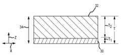
도 1은 본 발명의 전자 패키지의 단면도이고;
도 2는 본 발명의 전자 패키지의 열 인터페이스 부분의 단면도이고;
도 3은 본 발명의 전자 패키지의 열 인터페이스 부분의 사시도이고;
도 4는 본 발명의 전자 패키지의 일부분의 단면도이고;
도 5는 본 발명의 전자 패키지의 열 인터페이스 부분의 제조 공정을 설명하는 흐름도이고;
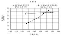
도 6은 비교 열 전도율 차트이고;
도 7a는 압축력 하의 본 발명의 전자 패키지의 단면도이고;
도 7b는 압축 이후의 본 발명의 전자 패키지의 단면도이다.Figure 1 is a cross-sectional view of an electronic package of the present invention;
FIG. 2 is a cross-sectional view of a thermal interface portion of the electronic package of the present invention;
FIG. 3 is a perspective view of a thermal interface portion of the electronic package of the present invention;
FIG. 4 is a cross-sectional view of a portion of an electronic package of the present invention;
FIG. 5 is a flow chart illustrating a manufacturing process of a thermal interface portion of an electronic package of the present invention;
Figure 6 is a comparative thermal conductivity chart;
FIG. 7a is a cross-sectional view of the electronic package of the present invention under compressive force;
FIG. 7b is a cross-sectional view of the electronic package of the present invention after compression.
바람직한 실시양태의 상세한 설명Detailed description of preferred embodiments
본 발명에 의해 제시된 다른 목적, 특징, 및 진보와 함께 상기 열거된 목적 및 이점은 이제 첨부된 도면 그림에 관하여 설명된 상세한 실시양태 측면에서 제시될 것이다. 본 발명의 다른 실시양태 및 측면은 관련 기술분야의 통상의 기술자의 이해 범위 내에 있는 것으로 인식된다.The above-mentioned objects and advantages, together with other objects, features, and advancements conferred by the present invention, will now be apparent from the detailed embodiments described with reference to the accompanying drawings. It is recognized that other embodiments and aspects of the present invention are within the scope of understanding of those skilled in the art.
본 발명의 장치를 설명하는 목적으로, 용어 "위쪽", "아래쪽", "수평", "수직", "위에", "아래에", "근위", "원위", 또는 유사한 관련 용어가 장치의 구성 부품 및 이들의 상대적 위치를 설명하기 위해 본원에서 사용될 수 있다. 이러한 용어는 첨부된 도면 그림에 관하여 편의상 사용되지만, 본 발명의 범주를 제한하는 것으로 해석되어서는 안 된다.For the purpose of describing the device of the present invention, the terms "upper", "lower", "horizontal", "vertical", "above", "below", "proximal", "distal", or similar related terms may be used herein to describe components of the device and their relative positions. Such terms are used for convenience with respect to the accompanying drawing figures, but should not be construed to limit the scope of the present invention.
이제 도면 그림, 및 먼저 도 1에 관하여, 전자 패키지(10)는 기판(12) 및 기판(12)에 고정된 복수의 전자 부품(16)을 포함하는 전자 부품 어레이(14)를 포함한다. 전자 패키지(10)는 열 소산기(18) 및 전자 부품 어레이(14)와 열 소산기(18) 사이의 열 경로 (대시 기호의 화살표(22)에 의해 표시됨)에 배치된 열 인터페이스(20)를 추가로 포함한다. 전자 패키지(10)는 전자 부품 어레이(14)로부터 열 소산기(18)와 접촉하는 열-흡수 유체 매체(24)까지 열 전도성 경로를 제공함으로써 전자 부품(16)에 의해 발생된 열 에너지를 소산시키도록 배열된다. 일반적인 적용에서, 유체 매체(24)는 열 소산기(18)로부터 열 에너지를 흡수하도록 공기 이동기에 의해 유발되는, 공기와 같은 기체일 수 있다. 전자 패키지(10)는 데이터 프로세서, 데이터 메모리, 의사 소통판, 안테나 등과 같은 다양한 전자 애플리케이션을 수용하도록 적절하게 변경될 수 있는 예시 배열체이다. 이러한 장치는 컴퓨팅 장치, 통신 장치, 및 이를 위한 주변기기에 활용될 수 있다. 특정 예시 실시양태에서, 전자 패키지(10)는 셀룰러 통신 장치에서 다양한 기능을 지원하기 위해 사용될 수 있다.Now referring to the drawing, and first to FIG. 1, an electronic package (10) includes a substrate (12) and an array of electronic components (14) including a plurality of electronic components (16) secured to the substrate (12). The electronic package (10) further includes a heat dissipator (18) and a thermal interface (20) positioned in a thermal path (represented by the dashed arrows (22)) between the electronic component array (14) and the heat dissipator (18). The electronic package (10) is arranged to dissipate thermal energy generated by the electronic components (16) by providing a thermally conductive path from the electronic component array (14) to a heat-absorbing fluid medium (24) in contact with the heat dissipator (18). In a typical application, the fluid medium (24) may be a gas, such as air, caused by an air mover to absorb thermal energy from the heat dissipator (18). The electronic package (10) is an exemplary arrangement that may be suitably modified to accommodate various electronic applications, such as a data processor, data memory, a communication board, an antenna, and the like. Such devices may be utilized in computing devices, communication devices, and peripherals therefor. In certain exemplary embodiments, the electronic package (10) may be used to support various functions in a cellular communication device.
기판(12)은 전자 부품 어레이(14)를 위한 지지체인 것에 더하여 다양한 기능 중 하나 이상의 역할을 할 수 있다. 본 발명의 전자 패키지(10)를 설명하는데 있어서 간략화를 위한 목적으로, 기판(12)은 조립체에서 필요에 따라 전자 부품(16)을 전기적으로 연결하기 위해 장착 표면(13)에 전기 전도성 트레이스를 갖는 인쇄 회로 기판과 같은 회로 기판일 수 있다. 부품(16)은 납땜 또는 다른 공지된 기술을 통해 배선 트레이스에 전기적으로 연결될 수 있다. 작동시, 전자 부품(16)은 최적의 성능을 유지하기 위해 소산되어야 하는 상당한 과잉 열 에너지를 발생시킨다. 전자 부품(16)은 전자 프로세스에 유용한 다양한 요소 중 임의의 것일 수 있고, 예를 들어, 집적 회로, 레지스터, 트랜지스터, 커패시터, 인덕터, 및 다이오드를 포함할 수 있다.In addition to being a support for the array of electronic components (14), the substrate (12) may serve one or more of a variety of functions. For purposes of simplicity in describing the electronic package (10) of the present invention, the substrate (12) may be a circuit board, such as a printed circuit board, having electrically conductive traces on a mounting surface (13) for electrically connecting electronic components (16) as needed in the assembly. The components (16) may be electrically connected to the wiring traces via soldering or other known techniques. During operation, the electronic components (16) generate significant excess heat energy that must be dissipated to maintain optimal performance. The electronic components (16) may be any of a variety of elements useful in electronic processing, including, for example, integrated circuits, resistors, transistors, capacitors, inductors, and diodes.
열 인터페이스(20)는 일반적으로 열 경로(22)를 따라 전자 부품 어레이(14)와 열 소산기(18) 사이에 열 전도성 브리지를 제공한다. 열 소산기(18)는 열 에너지를 열 소산기(18)에 가장 효율적으로 전달하는 방식으로 열 인터페이스(20)에 열적으로 결합될 수 있다. 개략적으로 도시된 바와 같이, 열 소산기(18)는, 예컨대 핀(28)을 통해, 비교적 높은 표면적을 포함하는 구성을 가질 수 있다. 열 소산기의 사용은 잘 이해되고, 기존의 맞춤형 디자인이 본 발명의 배열체에 활용될 수 있는 것으로 고려된다.The thermal interface (20) typically provides a thermally conductive bridge between the array of electronic components (14) and the heat dissipator (18) along the thermal path (22). The heat dissipator (18) may be thermally coupled to the thermal interface (20) in a manner that most efficiently transfers thermal energy to the heat dissipator (18). As schematically illustrated, the heat dissipator (18) may have a configuration that includes a relatively high surface area, such as via fins (28). The use of heat dissipators is well understood, and it is contemplated that existing custom designs may be utilized in the array of the present invention.
열 인터페이스에 대한 기존의 접근법은 페이스트 또는 겔과 같은 균일하고 유연한 열 전도성 덩어리를 포함한다. 또 다른 예시 인터페이스는 열 경로(22)에 실질적으로 평행하게 배향된 열 전도성 섬유를 갖는 배향된 섬유 장치를 포함한다. 상기 설명된 바와 같이, 이러한 해결책은 특정 적용에 부적절할 수 있다. 열 인터페이스(20)는 열 용량을 최대화하기 위해 인터페이스의 유연한 열 전도성 부피를 가장 효율적으로 활용하도록 개발되었다. 그렇게 하기 위해, 열 인터페이스(20)는 유연 층(32)으로 전달하기 전에 전자 부품(16)으로부터 수신된 열 에너지를 더 넓은 영역에 걸쳐 확산시키기 위해 열 확산 층(30)을 포함한다. 본 배열체에 의해 용이하게 되는 열 전달은 열 인터페이스(20)의 총 전도성 용량을 보다 충분히 활용하며, 이것은 전자 부품(16)과 같은 복수의 이격된 열원과 함께 사용될 경우 열 인터페이스(20)의 전체 열 전도율 성능을 상응하여 증가시킨다.Conventional approaches to thermal interfaces include a uniform, flexible thermally conductive mass, such as a paste or gel. Another exemplary interface includes an oriented fiber device having thermally conductive fibers oriented substantially parallel to the thermal path (22). As described above, such solutions may be inadequate for certain applications. The thermal interface (20) has been developed to most efficiently utilize the flexible thermally conductive volume of the interface to maximize thermal capacity. To do so, the thermal interface (20) includes a heat spreading layer (30) to spread the thermal energy received from the electronic component (16) over a wider area prior to transfer to the flexible layer (32). The heat transfer facilitated by the present arrangement more fully utilizes the overall conductive capacity of the thermal interface (20), which correspondingly increases the overall thermal conductivity performance of the thermal interface (20) when used with multiple, spaced heat sources, such as the electronic component (16).
열 인터페이스(20)는 열 확산 층(30) 및 유연 층(32)을 포함하는 다층 복합체일 수 있다. 열 인터페이스(20)는 열 확산 층(30)과 유연 층(32)을 통해 두께 축(34)을 따라 한정된 두께 "T"를 갖는다. 열 확산 층(30)은 두께 T의 20% 미만, 바람직하게는 T의 15% 미만, 보다 바람직하게는 두께 T의 10% 미만인 두께 "T1"을 갖는다. 일부 실시양태에서, 확산 층(30)은 열 인터페이스(20)의 두께 T의 5-10%인 두께 T1을 가질 수 있다.The thermal interface (20) can be a multilayer composite including a thermal diffusion layer (30) and a flexible layer (32). The thermal interface (20) has a thickness “T” defined along a thickness axis (34) through the thermal diffusion layer (30) and the flexible layer (32). The thermal diffusion layer (30) has a thickness “T1 ” that is less than 20% of the thickness T, preferably less than 15% of T, and more preferably less than 10% of the thickness T. In some embodiments, the diffusion layer (30) can have a thickness T1 that is 5-10% of the thickness T of the thermal interface (20).
열 확산 층(30)은 도 2 및 3에 도시된 바와 같이, 실질적으로 "x" 및 "y" 축을 따라 열 에너지의 분포를 촉진하기 위해 열 인터페이스(20)의 총 두께 T에 비해 상대적으로 얇다. 열 확산 층(30)은 바람직하게는 유연 층(32)의 제2 열 전도율 "C2"보다 실질적으로 큰 제1 열 전도율 "C1"을 나타낸다. 열 에너지가 최소 저항의 경로를 따라 전달되기 때문에, 열 확산 층(30)에서 열 인터페이스(20)에 의해 수신된 열 에너지는 유연 층(32)을 통해 전달되기 전에 열 확산 층(30) 전반에 주로 전달될 것이다. 이러한 "최소 저항의 경로" 효과는 전자 부품 어레이(14)의 개별 전자 부품(16)으로부터 투입된 열을 z 축을 통해 전달되기 전에 x 및 y 축 둘 다를 따라 열 확산 층(30) 전반에 주로 확산되게 한다. 이러한 방식으로, 열 에너지는 실질적으로 유연 층(32)의 제1 표면(33)에 나타난 인터페이스 영역 전반에 걸쳐, 그리고 그 후에 실질적으로 유연 층(32)의 전체 부피 전반에 걸쳐 유연 층(32)으로 전달된다. 이 접근법은 유연 층(32)의 열 전도도 용량을 최대화한다. 열 인터페이스(20)에 존재하는 열 확산 층(30) 없이, 기존의 페이스트 및 겔에서와 같이, 개별 열원 지점으로부터 투입된 열은 일반적으로 열 인터페이스 부피 전반에 걸쳐 전달되지 않고, 대신 두께 축을 따라 보다 직접적인 경로로 열 소산기에 전달된다.The heat spreading layer (30) is relatively thin compared to the total thickness T of the thermal interface (20) to facilitate distribution of thermal energy substantially along the "x" and "y" axes, as illustrated in FIGS. 2 and 3. The heat spreading layer (30) preferably exhibits a first thermal conductivity "C1 " that is substantially greater than the second thermal conductivity "C2 " of the flexible layer (32). Since thermal energy is transferred along the path of least resistance, thermal energy received by the thermal interface (20) in the heat spreading layer (30) will be transferred primarily throughout the heat spreading layer (30) before being transferred through the flexible layer (32). This "path of least resistance" effect causes heat input from individual electronic components (16) of the electronic component array (14) to be primarily spread throughout the heat spreading layer (30) along both the x and y axes before being transferred along the z axis. In this manner, thermal energy is transferred to the flexible layer (32) substantially across the interface region presented at the first surface (33) of the flexible layer (32), and thereafter substantially across the entire volume of the flexible layer (32). This approach maximizes the thermal conductivity capacity of the flexible layer (32). Without a heat spreading layer (30) present at the thermal interface (20), as in conventional pastes and gels, heat input from individual heat source points is typically not transferred across the entire volume of the thermal interface, but instead is transferred to the heat sink in a more direct path along the thickness axis.
열 확산 특성을 달성하기 위해, 열 확산 층(30)은 바람직하게는 적어도 100 W/m*K, 보다 바람직하게는 적어도 400 W/m*K의 제1 열 전도율 C1을 나타낸다. 일부 실시양태에서, 제1 열 전도율 C1은 100-1500 W/m*K, 보다 바람직하게는 400-1000 W/m*K일 수 있다. 본 발명의 목적을 위해, 층 또는 구조의 열 전도율은 ASTM D5470에 의해 결정된다. 열 확산 층(30)의 열 전도율은 3차원에서 실질적으로 동일할 수 있거나, 또는 실질적으로 x 및 y 축을 따라 우선적인 열 전달을 갖는 이방성일 수 있다. 다시 말해서, 열 확산 층(30)을 통한 열 전달은 바람직하게는 모든 3개의 축 (x, y, z)을 따라 실질적으로 동일하거나, 또는 도 2 및 3에 도시된 배향에서, z 축을 따른 열 전달에 비해 z 및 y 축을 따라 우선적인 열 전달을 나타낸다. x 및 y 축을 따른 열 확산의 목적을 달성하기 위해, x 및 y 축을 따른 열 전달에 비해 z 축을 따라 열을 우선적으로 전달하는 이방성 열 확산 층(30)을 사용하는 것은 바람직하지 않을 것이다. 열 확산 층(30)에 유용한 예시 재료는 구리, 알루미늄, 흑연, 및 질화붕소를 포함한다. 그러나, 다른 높은 열 전도성 재료도 본 발명의 열 확산 층(30)으로서 유용한 것으로 고려된다.To achieve the thermal spreading properties, the heat spreading layer (30) preferably exhibits a first thermal conductivity C1 of at least 100 W/m*K, more preferably at least 400 W/m*K. In some embodiments, the first thermal conductivity C1 can be 100-1500 W/m*K, more preferably 400-1000 W/m*K. For the purposes of the present invention, the thermal conductivity of the layer or structure is determined by ASTM D5470. The thermal conductivity of the heat spreading layer (30) can be substantially equal in three dimensions, or can be substantially anisotropic with preferential heat transfer along the x and y axes. In other words, heat transfer through the heat spreading layer (30) is preferably substantially equal along all three axes (x, y, z), or, in the orientations shown in FIGS. 2 and 3, exhibits preferential heat transfer along the z and y axes as compared to heat transfer along the z axis. To achieve the goal of heat spreading along the x and y axes, it would be undesirable to use an anisotropic heat spreading layer (30) that preferentially transfers heat along the z axis compared to heat transfer along the x and y axes. Example materials useful for the heat spreading layer (30) include copper, aluminum, graphite, and boron nitride. However, other high thermal conductivity materials are also contemplated to be useful as the heat spreading layer (30) of the present invention.
열 인터페이스(20)의 x 및 y 축을 따른 열 전달을 촉진하기 위해, 열 확산 층(30)은 바람직하게는 열 인터페이스(20)의 총 두께 T에 비해 두께 축(34)을 따라 상대적으로 얇다. 유연 층(32)과 비교하여 열 확산 층(30)의 실질적으로 더 큰 열 전도율로 인해, 상대적으로 얇은 열 확산 층(30)은 x 및 y 축을 따라 열 전달을 보다 효율적으로 유도한다. 그러나, 출원인은 x 및 y 축을 따라 열 전달을 유도하는 것과 전자 부품 어레이(14)로부터 투입된 열 에너지를 수용하기 위해 유연 층(32)으로 열을 조기에 전달하지 않고 열 확산 층(30)에 충분한 열 용량을 제공하는 것 사이의 균형에 바람직하게 이르게 되는 것을 발견하였다. 따라서, 적어도 일부 실시양태에서, 열 확산 층(30)에 대한 최소 두께 임계값은 두께 축(34)을 통해 개별 열원으로부터 보다 직접적인 열 전달을 초래할 수 있는 열 확산 층(30)의 총 열 용량을 "과부하"하지 않는 방식으로 열 에너지 투입을 수용하도록 바람직하게 유지된다. 따라서, 열 확산 이후의 두께 T1이 열 인터페이스(20)의 총 두께 T의 적어도 5%, 보다 바람직하게는 두께 T의 5-20%를 나타낼 수 있는 것이 바람직하다. 일부 실시양태에서, 열 확산 층 두께 T1은 25-125 마이크로미터일 수 있다.To facilitate heat transfer along the x and y axes of the thermal interface (20), the heat spreading layer (30) is preferably relatively thin along the thickness axis (34) relative to the total thickness T of the thermal interface (20). Due to the substantially greater thermal conductivity of the heat spreading layer (30) compared to the compliant layer (32), the relatively thin heat spreading layer (30) induces heat transfer along the x and y axes more efficiently. However, the Applicants have discovered that a desirable balance is achieved between inducing heat transfer along the x and y axes and providing sufficient thermal capacity to the heat spreading layer (30) without prematurely transferring heat to the compliant layer (32) to accommodate the thermal energy input from the electronic component array (14). Therefore, in at least some embodiments, the minimum thickness threshold for the heat spreading layer (30) is preferably maintained such that it accommodates the thermal energy input in a manner that does not "overload" the total thermal capacity of the heat spreading layer (30), which could result in more direct heat transfer from individual heat sources via the thickness axis (34). Thus, it is preferred that the thickness T1 after heat spreading can represent at least 5% of the total thickness T of the thermal interface (20), more preferably 5-20% of the thickness T. In some embodiments, the heat spreading layer thickness T1 can be 25-125 micrometers.
유연 층(32)은 바람직하게는 적어도 z 축을 따라 열 전도성이고, 바람직하게는 열 소산기(18)와의 열 접촉을 최대화하기 위해 순응성 재료이다. 유연 층(32)은 순응성 및 열 전도성 덩어리를 생성하기 위해 단독으로 또는 조합으로 사용될 수 있는 다양한 재료로부터 형성될 수 있다. 바람직하게, 유연 층(32)은 적어도 실온에서 자가-지지형이며, 여기서 유연 층(32)에 대한 한정된 3차원 형상은 적어도 실온에서 및 가해지는 외력 없이 자가-유지된다. 유연 층(32)을 위한 예시 재료는 미정질 왁스를 포함하거나 또는 실리콘-계 중합체는 실리콘 왁스, 실리콘 그리스, 및 실리콘 겔을 포함한다. 유연 층(32)에 유용한 제제의 예는 미국 특허 제5,950,066호 및 제6,197,859호에 기재된 것들을 포함하고, 이들의 내용은 본원에 참고로 포함된다. 일부 실시양태에서, 유연 층(32)은 약 40-80℃ 범위의 융점을 갖는 상-변화 재료를 포함할 수 있다.The flexible layer (32) is preferably thermally conductive at least along the z-axis, and is preferably a compliant material to maximize thermal contact with the heat dissipator (18). The flexible layer (32) can be formed from a variety of materials that can be used alone or in combination to create a compliant and thermally conductive mass. Preferably, the flexible layer (32) is self-supporting at least at room temperature, wherein the defined three-dimensional shape for the flexible layer (32) is self-maintained at least at room temperature and in the absence of applied external forces. Exemplary materials for the flexible layer (32) include microcrystalline waxes or silicone-based polymers including silicone waxes, silicone greases, and silicone gels. Examples of formulations useful for the flexible layer (32) include those described in U.S. Pat. Nos. 5,950,066 and 6,197,859, the contents of which are incorporated herein by reference. In some embodiments, the flexible layer (32) can include a phase-change material having a melting point in the range of about 40-80° C.
유연 층(32)은 열 전도율을 향상시키기 위해 내부에 분산된 열 전도성 미립자 물질을 추가로 포함할 수 있다. 예를 들어, 알루미나, 질화알루미늄, 질화붕소, 흑연, 탄화규소, 다이아몬드, 금속 분말, 세라믹 입자, 탄소 섬유 및 나노튜브, 금속 합금, 및 이들의 조합을 포함하여, 다양한 열 전도성 미립자 물질을 유연 층(32)의 열 전도율을 돕기 위해 활용할 수 있다. 최대 약 200 마이크로미터의 입자 크기가 일반적이다. 미립자 충전제 물질을 유연 층(32)에 약 10 내지 95 중량%의 농도로 제공할 수 있다. 미립자 충전제의 로딩 수준은 유연 층(32)의 전체 압축 모듈러스에 영향을 미칠 수 있다. 따라서, 실온에서 약 106 Pa 이하, 바람직하게는 104-106 Pa의 압축 모듈러스를 유지하는 것이 바람직하다. 이것의 목적을 위해, 용어 "압축 모듈러스"는 시험 절차 ASTM D575에 의해 정의된다.The flexible layer (32) may additionally include thermally conductive particulate materials dispersed therein to enhance thermal conductivity. For example, a variety of thermally conductive particulate materials may be utilized to aid in the thermal conductivity of the flexible layer (32), including alumina, aluminum nitride, boron nitride, graphite, silicon carbide, diamond, metal powders, ceramic particles, carbon fibers and nanotubes, metal alloys, and combinations thereof. Particle sizes up to about 200 micrometers are typical. The particulate filler material may be provided in the flexible layer (32) at a concentration of about 10 to 95 wt %. The loading level of the particulate filler may affect the overall compressive modulus of the flexible layer (32). Thus, it is desirable to maintain a compressive modulus of no greater than about 106 Pa, preferably 104 -106 Pa, at room temperature. For this purpose, the term "compressive modulus" is defined by test procedure ASTM D575.
유연 층(32)은 열 확산 층 열 전도율 C1보다 실질적으로 낮은 열 전도율 C2를 나타낼 수 있다. 낮은 열 임피던스/높은 열 전도율이 열 인터페이스에서 바람직하지만, 열 인터페이스 본체 자체의 열 전도율을 최대화하는 것은 순응성을 희생시킬 수 있다. 출원인은 순응성이 열 인터페이스 재료의 효율성을 관리함에 있어서 열 인터페이스 재료 내의 열 전도율보다 훨씬 더 중요할 수 있다는 것을 인식한다. 따라서, 열 인터페이스의 열 전도율과 열 인터페이스의 순응성 사이의 균형에 종종 이르게 된다. 본 발명의 장치는 압축 모듈러스에 의해 표현된 바와 같이, 유연 층(32)에서 순응성을 유지함으로써 이러한 균형에 이른다. 순응성 열 인터페이스 재료는 열 전도율이 다양할 수 있지만, 일반적으로는 20 W/m*K 미만이다. 따라서 유연 층(32)은 바람직하게는 적어도 z 축을 따라 1-15 W/m*K의 열 전도율을 나타낸다. 일부 바람직한 실시양태에서, 적어도 z 축을 따른 유연 층(32)의 열 전도율은 5-12 W/m*K이다. 유연 층(32) 및/또는 열 확산 층(30) 내의 다양한 지점에서 국소화된 열 전도율 값은 상기 기재된 값보다 적을 수 있다는 것을 이해해야 한다. 그러나, 적어도 z 축을 따른 순 열 전도율은 바람직하게는 상기 기재된 바와 같다.The compliant layer (32) can exhibit a thermal conductivity C2 substantially lower than the thermal conductivity C 1of the heat spreading layer. While low thermal impedance/high thermal conductivity is desirable in a thermal interface, maximizing the thermal conductivity of the thermal interface body itself can come at the expense of compliance. Applicants recognize that compliance can be much more important than thermal conductivity within the thermal interface material in managing the effectiveness of the thermal interface material. Thus, a balance is often reached between the thermal conductivity of the thermal interface and the compliance of the thermal interface. The devices of the present invention achieve this balance by maintaining compliance in the compliant layer (32), as expressed by the compressive modulus. The compliant thermal interface material can have a variety of thermal conductivities, but is typically less than 20 W/m*K. Thus, the compliant layer (32) preferably exhibits a thermal conductivity of at least along the z-axis of from 1 to 15 W/m*K. In some preferred embodiments, the thermal conductivity of the compliant layer (32) at least along the z-axis is from 5 to 12 W/m*K. It should be understood that the localized thermal conductivity values at various points within the flexible layer (32) and/or the heat spreading layer (30) may be less than those described above. However, the net thermal conductivity at least along the z-axis is preferably as described above.
유연 층(32)은 열 인터페이스(20)의 두께 T와 열 확산 층(30)의 균형을 형성할 수 있는 두께 치수 T2로 형성될 수 있다. 그러나, 열 확산 층(30) 및 유연 층(32) 이외에 층이 열 인터페이스(20)에 존재할 수 있다는 것이 고려된다. 일부 예시 실시양태에서, 유연 층(32)은 0.25-2.5 mm, 보다 바람직하게는 0.5-1 mm의 두께 T2를 가질 수 있다.The flexible layer (32) may be formed with a thickness dimension T2 that can form a balance between the thickness T of the thermal interface (20) and the heat diffusion layer (30). However, it is contemplated that other layers may be present at the thermal interface (20) in addition to the heat diffusion layer (30) and the flexible layer (32). In some exemplary embodiments, the flexible layer (32) may have a thickness T2 of 0.25-2.5 mm, more preferably 0.5-1 mm.
일부 실시양태에서, 접착 재료(40)는 전자 부품 어레이(14)에 열 확산 층(30)을 고정하기 위해 사용될 수 있다. 도 4에 도시된 바와 같이, 전자 부품 어레이(14)의 하나 이상의 전자 부품(16)에 열 확산 층(30)을 고정하기 위해 열 확산 층(30)에 접착 재료(40), 예컨대 감압 접착제를 적용할 수 있다. 접착 재료(40)는 어레이(14)의 하나 이상의 전자 부품(16)에 고정하기 위해 층으로 또는 개별 랜드로 제공될 수 있다. 접착 재료(40)는 열 전도성일 수 있고, 적어도 약 0.5 W/m*K의 전도율을 갖는다. 유용한 접착 재료의 예는 캘리포니아주 어바인 소재 헨켈 코포레이션(Henkel Corporation)으로부터 상업적으로 입수가능한 본드 플라이(Bond Ply)™ 및 리퀴본드(LiquiBond)™ 열 전도성 접착제를 포함한다.In some embodiments, an adhesive material (40) may be used to secure the heat spreading layer (30) to the electronic component array (14). As illustrated in FIG. 4, an adhesive material (40), such as a pressure-sensitive adhesive, may be applied to the heat spreading layer (30) to secure the heat spreading layer (30) to one or more electronic components (16) of the electronic component array (14). The adhesive material (40) may be provided in a layer or as individual lands to secure to one or more electronic components (16) of the array (14). The adhesive material (40) may be thermally conductive and have a conductivity of at least about 0.5 W/m*K. Examples of useful adhesive materials include Bond Ply™ and LiquiBond™ thermally conductive adhesives, commercially available from Henkel Corporation, Irvine, Calif.
열 인터페이스(20)는 바람직하게는 두께 축(34)을 따라 두께 T를 통해 전기 절연될 수 있다. 기존의 높은 열 전도성 인터페이스에 비해 열 인터페이스(20)의 이점은 전기 절연을 필요로 하는 적용에서의 열 인터페이스(20)의 적용성이다. 일부 기존의 높은 열 전도성 인터페이스는 전기 절연 특성을 상실하는 지점까지 전기 임피던스를 감소시키는 구조 및 조성에 의존한다. 높은 열 전도성 인터페이스에 대한 기존의 예시적인 접근법은 z 축을 따라 열 전도율을 촉진하기 위해 인터페이스의 두께를 통해 배항되는 배향 흑연을 사용한다. 그러나, 그렇게 할 때, 배향 흑연은 열 인터페이스를 통한 전기 전도성 경로를 형성한다. 특정 적용은 낮은 전기 저항 열 인터페이스에 적합하지 않다. 유연 층(32)은 바람직하게는 부도체이어서, 열 인터페이스(20)는 두께 축(34)을 따라 두께 T를 통해 적어도 108 Ω*cm의 전기 저항률을 나타낸다. 열 인터페이스(20)는 보다 바람직하게는 두께 축(34)을 따라 두께 T를 통해 적어도 1010 Ω*cm의 전기 저항률을 나타낼 수 있다.The thermal interface (20) is preferably electrically insulating through a thickness T along the thickness axis (34). An advantage of the thermal interface (20) over conventional high thermal conductivity interfaces is the applicability of the thermal interface (20) in applications requiring electrical insulation. Some conventional high thermal conductivity interfaces rely on structures and compositions that reduce the electrical impedance to the point where they lose their electrical insulating properties. A conventional exemplary approach to a high thermal conductivity interface uses oriented graphite distributed through the thickness of the interface to promote thermal conductivity along the z-axis. However, in doing so, the oriented graphite forms electrically conductive paths through the thermal interface. Certain applications are not suited to low electrical resistance thermal interfaces. The flexible layer (32) is preferably an electrical insulator, such that the thermal interface (20) exhibits an electrical resistivity of at least 108 Ω*cm through a thickness T along the thickness axis (34). The thermal interface (20) can more preferably exhibit an electrical resistivity of at least 1010 Ω*cm through a thickness T along the thickness axis (34).
열 확산 층(30)은, 예를 들어, 기상 증착, 플라즈마 중합, 스프레이 코팅, 스퍼터링 등을 포함하는 다양한 공정 중 하나를 통해 유연 층(32)에 조립될 수 있다는 것이 고려된다. 열 인터페이스 제조의 예시 공정 단계를 보여주는 흐름도는 도 5에 제시되어 있다. 특히, 열 확산 층(30)에 사용하기 위한 재료는 미리 결정된 두께로 이형 라이너 상에 증착되어 코팅된 기판을 형성한다. 일부 실시양태에서, 재료는 약 25-125 마이크로미터의 미리 결정된 두께로 기판에 적용될 수 있었다. 이형 라이너는 관련 기술분야에 잘 알려져 있고, 열 확산 층(30)으로부터 비교적 쉽게 제거될 수 있는 기존의 이형 라이너가 열 인터페이스 제조 공정에 활용될 수 있다는 것이 고려된다. 증착된 열 확산 층(30)을 수용하고, 후속적으로 그로부터 제거되는데 유용한 예시 이형 라이너는 폴리에틸렌 테레프탈레이트 (PET)이다.It is contemplated that the heat diffusion layer (30) may be assembled to the flexible layer (32) via any of a variety of processes including, for example, vapor deposition, plasma polymerization, spray coating, sputtering, and the like. A flow chart illustrating exemplary process steps for fabricating the thermal interface is presented in FIG. 5. In particular, a material for use in the heat diffusion layer (30) is deposited on a release liner at a predetermined thickness to form a coated substrate. In some embodiments, the material could be applied to the substrate at a predetermined thickness of about 25-125 micrometers. Release liners are well known in the art, and it is contemplated that existing release liners that are relatively easily removable from the heat diffusion layer (30) may be utilized in the thermal interface fabrication process. An exemplary release liner useful for receiving and subsequently removing the deposited heat diffusion layer (30) is polyethylene terephthalate (PET).
이어서 코팅된 기판은 이형 라이너가 캘린더링 롤과 접촉하고, 열 확산 층(30) 재료가 유연 층(32)과의 정합을 위해 노출되는 배향으로 캘린더링 작업에 배치된다. 열 확산 층(30)과 유연 층(32)의 정합은 열 확산 층(30)과 그의 각각의 이형 라이너 기판 사이의 결합보다 큰 강도로 열 확산 층(30)을 유연 층(32)에 부착되게 한다. 결과적으로, 기판은 이어서 열 확산 층(30)으로부터 제거되고 한편 열 확산 층(30)은 유연 층(32)과 접촉한 채 있다. 이어서 개별 열 인터페이스는 원하는 크기로 다이 절단될 수 있다.The coated substrate is then placed in a calendering operation with the release liner in contact with the calendering roll and the heat spreading layer (30) material exposed for mating with the compliant layer (32). The mating of the heat spreading layer (30) and the compliant layer (32) causes the heat spreading layer (30) to adhere to the compliant layer (32) with a strength greater than the bond between the heat spreading layer (30) and its respective release liner substrate. As a result, the substrate is then removed from the heat spreading layer (30) while the heat spreading layer (30) remains in contact with the compliant layer (32). The individual thermal interfaces can then be die cut to a desired size.
본 발명의 측면은 열 인터페이스(20)가 두께 축(34)을 따른 압축 이후에 그의 열 전도율 성능을 거의 잃지 않는 방법이다. 특정 열 인터페이스의 열 전도율 성능은 압축시 상당히 저하된다. 이것은, 예를 들어, 열 전도율 성능을 달성하기 위해 의존하는 배향된 섬유의 파괴로 인한 것일 수 있다. 본 발명의 열 인터페이스(20)의 구조는 그의 열 성능에 대한 상당한 저하 없이 두께 축(34)을 따른 압축을 허용한다.An aspect of the present invention is a method in which a thermal interface (20) loses little or no thermal conductivity performance after compression along the thickness axis (34). The thermal conductivity performance of certain thermal interfaces degrades significantly upon compression. This may be due, for example, to the destruction of the oriented fibers upon which they depend to achieve their thermal conductivity performance. The structure of the thermal interface (20) of the present invention allows compression along the thickness axis (34) without significant degradation of its thermal performance.
도 6은 본 발명의 0.08 인치 공칭 10 W/m*K 열 인터페이스와 비교하여 0.07 인치의 초기 두께를 갖는 공칭 20 W/m*K 배향 흑연 열 인터페이스의 각각의 두께 축을 따른 점진적인 압축시 열 성능의 비교를 보여준다. 특히, 도 6의 비교 데이터는 배향 흑연 인터페이스가 압축시 열 전도율에서 급격하게 감소하는 반면, 본 배열체의 열 전도율은 상당한 압축시에도 거의 영향을 받지 않는다는 것을 보여준다. 바람직한 실시양태에서, 최대 50%의 두께 감소를 갖는 열 인터페이스(20)는 그의 초기 열 전도율의 적어도 80%인 압축 열 전도율을 나타낸다. 도 6에 도시된 바와 같이, 공칭 10 W/m*K 열 인터페이스의 열 전도율은 그의 두께 축을 따라 50%만큼 압축한 후 20% 미만만큼 감소된다.FIG. 6 shows a comparison of the thermal performance along each thickness axis of a nominal 20 W/m*K oriented graphite thermal interface having an initial thickness of 0.07 inches compared to a nominal 10 W/m*K thermal interface of the present invention with progressive compression. In particular, the comparative data of FIG. 6 shows that the oriented graphite interface exhibits a rapid decrease in thermal conductivity upon compression, whereas the thermal conductivity of the present arrangement is virtually unaffected even with significant compression. In a preferred embodiment, the thermal interface (20) having a thickness reduction of up to 50% exhibits a compression thermal conductivity that is at least 80% of its initial thermal conductivity. As illustrated in FIG. 6, the thermal conductivity of the nominal 10 W/m*K thermal interface is reduced by less than 20% after compression by 50% along its thickness axis.
도 7a 및 7b는 본 발명의 전자 패키지를 제조하는 방법을 도시하며, 여기서 열 인터페이스(20)는 열 소산기(18)와 기판(12)에 고정된 복수의 전자 부품(16)의 전자 부품 어레이(14) 사이의 열 경로(22)에 부착된다. 열 인터페이스(20)는 힘 벡터 F1, F2에 의해 나타낸 바와 같이, 열 소산기(18) 및 기판(12) 중 하나 또는 둘 다에 힘을 가함으로써 두께 축(34)을 따라 압축된다. 전자 패키지(10)를 원하는 정도로 압축하기 위해 기존의 압축 메커니즘을 이용할 수 있다. 일부 실시양태에서, 전자 패키지(10)는 열 인터페이스(20)의 두께 T가 최대 50%만큼 감소되게 하는 정도로 두께 축(34)을 따라 압축될 수 있다. 도 7b는 압축 공정 이후의 전자 패키지(10)를 도시한다. 열 소산기(18), 전자 부품 어레이(14), 및 기판(12) 각각은 열 인터페이스(20)에 비해 상대적으로 비압축성이다. 일부 실시양태에서, 열 인터페이스(20)의 열 확산 층(30)은 유연 층(32)에 비해 상대적으로 비압축성이다. 이러한 실시양태에서, 전자 패키지(10)에 가해진 압축력 F1, F2는 주로 열 인터페이스(20)의 유연 층(32)만 압축할 수 있다. 도 7a 및 7b에 도시된 예에서, 열 인터페이스(20)의 초기 두께 Ti는 최대 약 50%만큼 감소될 수 있고, 여기서 최종 두께 Tf는 다음 관계로 표현될 수 있다:FIGS. 7A and 7B illustrate a method of manufacturing an electronic package of the present invention, wherein a thermal interface (20) is attached to a thermal path (22) between a heat dissipator (18) and an electronic component array (14) of a plurality of electronic components (16) secured to a substrate (12). The thermal interface (20) is compressed along a thickness axis (34) by applying a force to one or both of the heat dissipator (18) and the substrate (12), as represented by force vectors F1 and F2 . Any conventional compression mechanism can be utilized to compress the electronic package (10) to a desired degree. In some embodiments, the electronic package (10) can be compressed along the thickness axis (34) to such an extent that the thickness T of the thermal interface (20) is reduced by up to 50%. FIG. 7B illustrates the electronic package (10) after the compression process. The heat dissipator (18), the electronic component array (14), and the substrate (12) are each relatively incompressible relative to the thermal interface (20). In some embodiments, the heat spreading layer (30) of the thermal interface (20) is relatively incompressible relative to the flexible layer (32). In such embodiments, the compressive forces F1 , F2 applied to the electronic package (10) may primarily compress only the flexible layer (32) of the thermal interface (20). In the examples illustrated in FIGS. 7a and 7b , the initial thickness Ti of the thermal interface (20) may be reduced by up to about 50%, whereby the final thickness Tf may be expressed by the following relationship:
Tf = 0.5 ≤ Ti ≤ 1.0Tf = 0.5 ≤ Ti ≤ 1.0
상기 설명된 바와 같이, 열 인터페이스(20)는 그렇게 압축될 수 있지만 그의 열 전도율 성능을 실질적으로 유지할 수 있다는 것이 출원인에 의해 발견되었다. 이러한 특성은 조립 동안 압축을 필요로 하거나 또는 활용하는 적용에서 중요하다.As described above, it has been discovered by the applicant that the thermal interface (20) can be compressed while substantially maintaining its thermal conductivity performance. This property is important in applications that require or utilize compression during assembly.
신규 원리를 적용하고 필요에 따라 본 발명의 실시양태를 구성 및 사용하는데 필요한 정보를 통상의 기술자에게 제공하기 위해 본 발명을 본원에서 상당히 상세하게 설명하였다. 그러나, 본 발명 자체의 범주를 벗어나지 않으면서 다양한 변형이 달성될 수 있다는 것을 이해해야 한다.The invention has been described in considerable detail herein to provide those skilled in the art with the information necessary to apply the novel principles and to construct and use embodiments of the invention as needed. However, it should be understood that various modifications may be made without departing from the scope of the invention itself.
Claims (20)
Translated fromKorean상기 기판에 고정된 복수의 개별 이격된 전자 부품을 포함하는 전자 부품 어레이;
열 소산기; 및
상기 전자 부품 어레이와 상기 열 소산기 사이의 열 경로에 배치된 열 인터페이스로서, 상기 열 인터페이스는 열 확산 층 및 유연 층, 및 상기 열 확산 층과 상기 유연 층을 통해 두께 축을 따라 한정된 두께를 포함하고, 여기서 상기 열 확산 층은 두께의 20% 미만이고 제1 열 전도율을 나타내고, 상기 유연 층은 제1 열 전도율보다 실질적으로 낮은 제2 열 전도율 및 104 Pa - 106 Pa의 압축 모듈러스를 나타내고, 여기서 상기 열 확산 층은 상기 전자 부품 어레이에 열적으로 연결된 것인, 열 인터페이스
를 포함하는 전자 패키지.substrate;
An array of electronic components comprising a plurality of individually spaced electronic components secured to the substrate;
heat dissipator; and
A thermal interface disposed in a thermal path between the array of electronic components and the heat dissipator, the thermal interface comprising a heat spreading layer and a flexible layer, and a thickness defined along a thickness axis through the heat spreading layer and the flexible layer, wherein the heat spreading layer is less than 20% of the thickness and exhibits a first thermal conductivity, and the flexible layer exhibits a second thermal conductivity substantially lower than the first thermal conductivity and a compressive modulus of 104 Pa to 106 Pa, wherein the heat spreading layer is thermally connected to the array of electronic components.
Electronic package containing .
a. 열 확산 층 및 유연 층, 및 상기 열 확산 층과 상기 유연 층을 통해 두께 축을 따라 한정된 두께를 갖는 열 인터페이스를 제공하는 단계로서, 여기서 상기 열 인터페이스는 초기 열 전도율을 나타내고, 상기 열 확산 층은 두께의 20% 미만이고 적어도 100 W/m*K의 열 전도율을 나타내고, 상기 유연 층은 104 Pa - 106 Pa의 압축 모듈러스를 나타내는 것인 단계;
b. 열 소산기와 기판에 고정된 복수의 전자 부품의 전자 부품 어레이 사이의 열 경로에 상기 열 인터페이스를 부착하는 단계; 및
c. 두께 축을 따라 상기 열 인터페이스를 압축하여 상기 두께를 감소시키는 단계로서, 여기서 최대 50%의 두께 감소를 갖는 열 인터페이스는 초기 열 전도율의 적어도 80%인 압축 열 전도율을 나타내는 것인 단계;
여기서 상기 열 확산 층은 상기 전자 부품 어레이에 열적으로 연결된 것인 방법.A method for manufacturing an electronic package, comprising the steps of:
a. A step of providing a thermal interface having a defined thickness along a thickness axis through a heat diffusion layer and a flexible layer, wherein the thermal interface exhibits an initial thermal conductivity, the heat diffusion layer exhibits a thermal conductivity of less than 20% of the thickness and at least 100 W/m*K, and the flexible layer exhibits a compressive modulus of 104 Pa to 106 Pa;
b. attaching said thermal interface to a thermal path between a heat dissipator and an electronic component array of a plurality of electronic components secured to the substrate; and
c. A step of compressing the thermal interface along the thickness axis to reduce the thickness, wherein the thermal interface having a thickness reduction of up to 50% exhibits a compressed thermal conductivity of at least 80% of the initial thermal conductivity;
A method wherein said heat spreading layer is thermally connected to said array of electronic components.
상기 기판에 고정된 복수의 개별 이격된 전자 부품을 포함하는 전자 부품 어레이;
열 확산 층 및 유연 층, 및 상기 열 확산 층과 상기 유연 층을 통해 두께 축을 따라 한정된 두께를 포함하는 열 인터페이스로서, 여기서 상기 열 확산 층은 두께의 20% 미만이고 제1 열 전도율을 나타내고, 상기 유연 층은 제1 열 전도율보다 실질적으로 낮은 제2 열 전도율 및 104 Pa - 106 Pa의 압축 모듈러스를 나타내고, 상기 열 확산 층은 상기 전자 부품 어레이에 열적으로 연결된 것인, 열 인터페이스; 및
상기 열 인터페이스의 상기 유연 층에 열적으로 연결된 열 소산기
를 포함하는 전자 패키지.substrate;
An array of electronic components comprising a plurality of individually spaced electronic components secured to the substrate;
A thermal interface comprising a heat spreading layer and a flexible layer, and a thickness defined along a thickness axis through the heat spreading layer and the flexible layer, wherein the heat spreading layer is less than 20% of the thickness and exhibits a first thermal conductivity, and the flexible layer exhibits a second thermal conductivity substantially less than the first thermal conductivity and a compressive modulus of 104 Pa to 106 Pa, wherein the heat spreading layer is thermally connected to the array of electronic components; and
A heat dissipator thermally connected to the flexible layer of the above thermal interface.
Electronic package containing .
Applications Claiming Priority (3)
| Application Number | Priority Date | Filing Date | Title |
|---|---|---|---|
| US201962877495P | 2019-07-23 | 2019-07-23 | |
| US62/877,495 | 2019-07-23 | ||
| PCT/US2020/043116WO2021016378A1 (en) | 2019-07-23 | 2020-07-22 | Thermal management of high heat flux multicomponent assembly |
Publications (2)
| Publication Number | Publication Date |
|---|---|
| KR20220035046A KR20220035046A (en) | 2022-03-21 |
| KR102829764B1true KR102829764B1 (en) | 2025-07-07 |
Family
ID=74192675
Family Applications (1)
| Application Number | Title | Priority Date | Filing Date |
|---|---|---|---|
| KR1020217042798AActiveKR102829764B1 (en) | 2019-07-23 | 2020-07-22 | Thermal management of high-temperature flux multi-component assemblies |
Country Status (6)
| Country | Link |
|---|---|
| US (1) | US12238899B2 (en) |
| EP (1) | EP4004975A4 (en) |
| JP (1) | JP7741792B2 (en) |
| KR (1) | KR102829764B1 (en) |
| CN (1) | CN114144877A (en) |
| WO (1) | WO2021016378A1 (en) |
Families Citing this family (1)
| Publication number | Priority date | Publication date | Assignee | Title |
|---|---|---|---|---|
| US20240030084A1 (en)* | 2022-07-25 | 2024-01-25 | Taiwan Semiconductor Manufacturing Company, Ltd. | 3d semiconductor package |
Citations (4)
| Publication number | Priority date | Publication date | Assignee | Title |
|---|---|---|---|---|
| JP2005033156A (en) | 2003-06-18 | 2005-02-03 | Shin Etsu Polymer Co Ltd | Electromagnetic wave absorption sheet, electronic apparatus, and method of manufacturing electromagnetic wave absorption sheet |
| US20170186628A1 (en) | 2015-12-23 | 2017-06-29 | Intel Corporation | Integrated heat spreader having electromagnetically-formed features |
| US20170263539A1 (en) | 2013-03-14 | 2017-09-14 | General Electric Company | Power overlay structure and method of making same |
| US20180014431A1 (en) | 2015-06-29 | 2018-01-11 | Huawei Technologies Co., Ltd. | Thermal Pad and Electronic Device |
Family Cites Families (43)
| Publication number | Priority date | Publication date | Assignee | Title |
|---|---|---|---|---|
| DE3777522D1 (en) | 1986-10-17 | 1992-04-23 | Hitachi Ltd | METHOD FOR PRODUCING A MIXED STRUCTURE FOR SEMICONDUCTOR ARRANGEMENT. |
| US4938992A (en) | 1988-01-07 | 1990-07-03 | Varian Associates, Inc. | Methods for thermal transfer with a semiconductor |
| US5300809A (en) | 1989-12-12 | 1994-04-05 | Sumitomo Special Metals Co., Ltd. | Heat-conductive composite material |
| US6197859B1 (en) | 1993-06-14 | 2001-03-06 | The Bergquist Company | Thermally conductive interface pads for electronic devices |
| US6090484A (en) | 1995-05-19 | 2000-07-18 | The Bergquist Company | Thermally conductive filled polymer composites for mounting electronic devices and method of application |
| US5679457A (en) | 1995-05-19 | 1997-10-21 | The Bergquist Company | Thermally conductive interface for electronic devices |
| JPH098185A (en)* | 1995-06-23 | 1997-01-10 | Hitachi Ltd | Package with electronic component cooling structure and method of manufacturing the same |
| JP4080030B2 (en) | 1996-06-14 | 2008-04-23 | 住友電気工業株式会社 | Semiconductor substrate material, semiconductor substrate, semiconductor device, and manufacturing method thereof |
| US5950066A (en) | 1996-06-14 | 1999-09-07 | The Bergquist Company | Semisolid thermal interface with low flow resistance |
| US5738936A (en) | 1996-06-27 | 1998-04-14 | W. L. Gore & Associates, Inc. | Thermally conductive polytetrafluoroethylene article |
| JP3425521B2 (en) | 1998-01-09 | 2003-07-14 | 信越化学工業株式会社 | Method for reducing surface tackiness of low hardness thermally conductive silicone rubber sheet |
| US6399209B1 (en) | 1999-04-16 | 2002-06-04 | The Bergquist Company | Integrated release films for phase-change interfaces |
| US6162663A (en) | 1999-04-20 | 2000-12-19 | Schoenstein; Paul G. | Dissipation of heat from a circuit board having bare silicon chips mounted thereon |
| US6359334B1 (en) | 1999-06-08 | 2002-03-19 | Micron Technology, Inc. | Thermally conductive adhesive tape for semiconductor devices and method using the same |
| US20070241303A1 (en) | 1999-08-31 | 2007-10-18 | General Electric Company | Thermally conductive composition and method for preparing the same |
| US6667548B2 (en) | 2001-04-06 | 2003-12-23 | Intel Corporation | Diamond heat spreading and cooling technique for integrated circuits |
| US6657296B2 (en) | 2001-09-25 | 2003-12-02 | Siliconware Precision Industries Co., Ltd. | Semicondctor package |
| US6597575B1 (en)* | 2002-01-04 | 2003-07-22 | Intel Corporation | Electronic packages having good reliability comprising low modulus thermal interface materials |
| US6657297B1 (en) | 2002-08-15 | 2003-12-02 | The Bergquist Company | Flexible surface layer film for delivery of highly filled or low cross-linked thermally conductive interface pads |
| US6919504B2 (en) | 2002-12-19 | 2005-07-19 | 3M Innovative Properties Company | Flexible heat sink |
| US6841867B2 (en) | 2002-12-30 | 2005-01-11 | Intel Corporation | Gel thermal interface materials comprising fillers having low melting point and electronic packages comprising these gel thermal interface materials |
| US20070164424A1 (en) | 2003-04-02 | 2007-07-19 | Nancy Dean | Thermal interconnect and interface systems, methods of production and uses thereof |
| US20050016714A1 (en) | 2003-07-09 | 2005-01-27 | Chung Deborah D.L. | Thermal paste for improving thermal contacts |
| US6898084B2 (en) | 2003-07-17 | 2005-05-24 | The Bergquist Company | Thermal diffusion apparatus |
| US8211260B2 (en) | 2003-10-14 | 2012-07-03 | Graftech International Holdings Inc. | Heat spreader for plasma display panel |
| JP4368737B2 (en) | 2004-05-14 | 2009-11-18 | 信越ポリマー株式会社 | Electromagnetic wave noise suppressor and method for manufacturing the same |
| US7215551B2 (en)* | 2004-09-29 | 2007-05-08 | Super Talent Electronics, Inc. | Memory module assembly including heat sink attached to integrated circuits by adhesive |
| TWI306296B (en) | 2006-04-06 | 2009-02-11 | Siliconware Precision Industries Co Ltd | Semiconductor device with a heat sink and method for fabricating the same |
| US8076773B2 (en) | 2007-12-26 | 2011-12-13 | The Bergquist Company | Thermal interface with non-tacky surface |
| JP5243975B2 (en)* | 2008-02-04 | 2013-07-24 | 新光電気工業株式会社 | Semiconductor package heat dissipating part having heat conducting member and method of manufacturing the same |
| JP6055698B2 (en) | 2013-03-05 | 2016-12-27 | 日立オートモティブシステムズ株式会社 | Electronic control device, heat dissipation structure thereof, and electronic device equipped with the electronic control device |
| JP6250997B2 (en) | 2013-09-17 | 2017-12-20 | 日立オートモティブシステムズ株式会社 | Electronic control unit |
| US20150092352A1 (en) | 2013-09-29 | 2015-04-02 | International Business Machines Corporation | Thermal Interface Solution With Reduced Adhesion Force |
| WO2015120773A1 (en) | 2014-02-13 | 2015-08-20 | Honeywell International Inc. | Compressible thermal interface materials |
| US9611414B2 (en) | 2014-07-11 | 2017-04-04 | Henkel IP & Holding GmbH | Thermal interface material with mixed aspect ratio particle dispersions |
| US9546764B2 (en) | 2014-07-25 | 2017-01-17 | Graftech International Holdings Inc. | Display device with flexible circuit board having graphite substrate |
| DE102015108700B4 (en) | 2015-06-02 | 2025-01-09 | Infineon Technologies Austria Ag | Semiconductor power package and method for its manufacture |
| JP6600224B2 (en) | 2015-10-20 | 2019-10-30 | 積水化学工業株式会社 | Thermal conductive sheet for electronic equipment |
| WO2017123188A1 (en) | 2016-01-11 | 2017-07-20 | Intel Corporation | Multiple-chip package with multiple thermal interface materials |
| JP6301978B2 (en) | 2016-01-26 | 2018-03-28 | デクセリアルズ株式会社 | HEAT CONDUCTIVE SHEET, HEAT CONDUCTIVE SHEET MANUFACTURING METHOD, HEAT DISSIBLING MEMBER AND SEMICONDUCTOR DEVICE |
| JP6675543B2 (en) | 2016-02-05 | 2020-04-01 | 北川工業株式会社 | Heat conductive member, method for manufacturing heat conductive member, and silicone mixture |
| US10319609B2 (en)* | 2017-06-21 | 2019-06-11 | International Business Machines Corporation | Adhesive-bonded thermal interface structures |
| US11094608B2 (en)* | 2018-06-29 | 2021-08-17 | Taiwan Semiconductor Manufacturing Co., Ltd. | Heat dissipation structure including stacked chips surrounded by thermal interface material rings |
- 2020
- 2020-07-22CNCN202080052870.7Apatent/CN114144877A/enactivePending
- 2020-07-22KRKR1020217042798Apatent/KR102829764B1/enactiveActive
- 2020-07-22JPJP2022504177Apatent/JP7741792B2/enactiveActive
- 2020-07-22EPEP20844987.6Apatent/EP4004975A4/enactivePending
- 2020-07-22WOPCT/US2020/043116patent/WO2021016378A1/ennot_activeCeased
- 2022
- 2022-01-24USUS17/582,275patent/US12238899B2/enactiveActive
Patent Citations (4)
| Publication number | Priority date | Publication date | Assignee | Title |
|---|---|---|---|---|
| JP2005033156A (en) | 2003-06-18 | 2005-02-03 | Shin Etsu Polymer Co Ltd | Electromagnetic wave absorption sheet, electronic apparatus, and method of manufacturing electromagnetic wave absorption sheet |
| US20170263539A1 (en) | 2013-03-14 | 2017-09-14 | General Electric Company | Power overlay structure and method of making same |
| US20180014431A1 (en) | 2015-06-29 | 2018-01-11 | Huawei Technologies Co., Ltd. | Thermal Pad and Electronic Device |
| US20170186628A1 (en) | 2015-12-23 | 2017-06-29 | Intel Corporation | Integrated heat spreader having electromagnetically-formed features |
Also Published As
| Publication number | Publication date |
|---|---|
| TW202105643A (en) | 2021-02-01 |
| US12238899B2 (en) | 2025-02-25 |
| WO2021016378A1 (en) | 2021-01-28 |
| EP4004975A1 (en) | 2022-06-01 |
| CN114144877A (en) | 2022-03-04 |
| US20220151108A1 (en) | 2022-05-12 |
| JP2022541611A (en) | 2022-09-26 |
| JP7741792B2 (en) | 2025-09-18 |
| KR20220035046A (en) | 2022-03-21 |
| EP4004975A4 (en) | 2023-08-09 |
Similar Documents
| Publication | Publication Date | Title |
|---|---|---|
| US4810563A (en) | Thermally conductive, electrically insulative laminate | |
| US20200294817A1 (en) | 3DIC Package Comprising Perforated Foil Sheet | |
| US6459582B1 (en) | Heatsink apparatus for de-coupling clamping forces on an integrated circuit package | |
| US7872869B2 (en) | Electronic chip module | |
| US20050104197A1 (en) | Carbon-carbon and/or metal-carbon fiber composite heat spreaders | |
| KR101682761B1 (en) | Thermally conductive dielectric interface | |
| US7760507B2 (en) | Thermally and electrically conductive interconnect structures | |
| JP2003188323A (en) | Graphite sheet and its manufacturing method | |
| CN110098153B (en) | Power electronic module and method of manufacturing a power electronic module | |
| US6552907B1 (en) | BGA heat ball plate spreader, BGA to PCB plate interface | |
| EP3740968B1 (en) | Power electronics module and a method of producing a power electronics module | |
| KR102829764B1 (en) | Thermal management of high-temperature flux multi-component assemblies | |
| TWI896542B (en) | Thermal management of high heat flux multicomponent assembly | |
| JP2017183677A (en) | Circuit module and its manufacturing method | |
| WO2000069236A1 (en) | A thermally enhanced via/bga microwave circuit ceramic package | |
| US12205864B2 (en) | Thermal interface materials for the interior, center, and exterior of an electronic component | |
| JP2003068954A (en) | Package for storing semiconductor elements | |
| JP2001523047A (en) | Non-conductive heat dissipator components | |
| JP2004221328A (en) | Semiconductor element storage package and semiconductor device | |
| CN115735419A (en) | Multilayer circuit board and electronic component mounting multilayer board | |
| KR20050072257A (en) | Thermal pad using dlc coating | |
| HK1147642B (en) | Thermally and electrically conductive interconnect structures | |
| JP2001217361A (en) | Heat radiating material, semiconductor device and electronic device using the same | |
| JPH06103724B2 (en) | Semiconductor chip carrier | |
| JP2003007887A (en) | Package for storing semiconductor elements |
Legal Events
| Date | Code | Title | Description |
|---|---|---|---|
| PA0105 | International application | St.27 status event code:A-0-1-A10-A15-nap-PA0105 | |
| PG1501 | Laying open of application | St.27 status event code:A-1-1-Q10-Q12-nap-PG1501 | |
| PA0201 | Request for examination | St.27 status event code:A-1-2-D10-D11-exm-PA0201 | |
| E902 | Notification of reason for refusal | ||
| PE0902 | Notice of grounds for rejection | St.27 status event code:A-1-2-D10-D21-exm-PE0902 | |
| P11-X000 | Amendment of application requested | St.27 status event code:A-2-2-P10-P11-nap-X000 | |
| E701 | Decision to grant or registration of patent right | ||
| PE0701 | Decision of registration | St.27 status event code:A-1-2-D10-D22-exm-PE0701 | |
| PN2301 | Change of applicant | St.27 status event code:A-3-3-R10-R11-asn-PN2301 | |
| GRNT | Written decision to grant | ||
| PR0701 | Registration of establishment | St.27 status event code:A-2-4-F10-F11-exm-PR0701 | |
| PR1002 | Payment of registration fee | St.27 status event code:A-2-2-U10-U12-oth-PR1002 Fee payment year number:1 | |
| PG1601 | Publication of registration | St.27 status event code:A-4-4-Q10-Q13-nap-PG1601 |