KR102826092B1 - Energy conversion device and safety control method thereof - Google Patents
Energy conversion device and safety control method thereofDownload PDFInfo
- Publication number
- KR102826092B1 KR102826092B1KR1020237000097AKR20237000097AKR102826092B1KR 102826092 B1KR102826092 B1KR 102826092B1KR 1020237000097 AKR1020237000097 AKR 1020237000097AKR 20237000097 AKR20237000097 AKR 20237000097AKR 102826092 B1KR102826092 B1KR 102826092B1
- Authority
- KR
- South Korea
- Prior art keywords
- switch module
- capacitor
- motor inverter
- battery
- controlling
- Prior art date
- Legal status (The legal status is an assumption and is not a legal conclusion. Google has not performed a legal analysis and makes no representation as to the accuracy of the status listed.)
- Active
Links
Images


Classifications
- H—ELECTRICITY
- H02—GENERATION; CONVERSION OR DISTRIBUTION OF ELECTRIC POWER
- H02P—CONTROL OR REGULATION OF ELECTRIC MOTORS, ELECTRIC GENERATORS OR DYNAMO-ELECTRIC CONVERTERS; CONTROLLING TRANSFORMERS, REACTORS OR CHOKE COILS
- H02P27/00—Arrangements or methods for the control of AC motors characterised by the kind of supply voltage
- H02P27/04—Arrangements or methods for the control of AC motors characterised by the kind of supply voltage using variable-frequency supply voltage, e.g. inverter or converter supply voltage
- H02P27/06—Arrangements or methods for the control of AC motors characterised by the kind of supply voltage using variable-frequency supply voltage, e.g. inverter or converter supply voltage using DC to AC converters or inverters
- H02P27/08—Arrangements or methods for the control of AC motors characterised by the kind of supply voltage using variable-frequency supply voltage, e.g. inverter or converter supply voltage using DC to AC converters or inverters with pulse width modulation
- B—PERFORMING OPERATIONS; TRANSPORTING
- B60—VEHICLES IN GENERAL
- B60L—PROPULSION OF ELECTRICALLY-PROPELLED VEHICLES; SUPPLYING ELECTRIC POWER FOR AUXILIARY EQUIPMENT OF ELECTRICALLY-PROPELLED VEHICLES; ELECTRODYNAMIC BRAKE SYSTEMS FOR VEHICLES IN GENERAL; MAGNETIC SUSPENSION OR LEVITATION FOR VEHICLES; MONITORING OPERATING VARIABLES OF ELECTRICALLY-PROPELLED VEHICLES; ELECTRIC SAFETY DEVICES FOR ELECTRICALLY-PROPELLED VEHICLES
- B60L53/00—Methods of charging batteries, specially adapted for electric vehicles; Charging stations or on-board charging equipment therefor; Exchange of energy storage elements in electric vehicles
- H—ELECTRICITY
- H02—GENERATION; CONVERSION OR DISTRIBUTION OF ELECTRIC POWER
- H02P—CONTROL OR REGULATION OF ELECTRIC MOTORS, ELECTRIC GENERATORS OR DYNAMO-ELECTRIC CONVERTERS; CONTROLLING TRANSFORMERS, REACTORS OR CHOKE COILS
- H02P27/00—Arrangements or methods for the control of AC motors characterised by the kind of supply voltage
- H02P27/04—Arrangements or methods for the control of AC motors characterised by the kind of supply voltage using variable-frequency supply voltage, e.g. inverter or converter supply voltage
- H02P27/06—Arrangements or methods for the control of AC motors characterised by the kind of supply voltage using variable-frequency supply voltage, e.g. inverter or converter supply voltage using DC to AC converters or inverters
- B—PERFORMING OPERATIONS; TRANSPORTING
- B60—VEHICLES IN GENERAL
- B60L—PROPULSION OF ELECTRICALLY-PROPELLED VEHICLES; SUPPLYING ELECTRIC POWER FOR AUXILIARY EQUIPMENT OF ELECTRICALLY-PROPELLED VEHICLES; ELECTRODYNAMIC BRAKE SYSTEMS FOR VEHICLES IN GENERAL; MAGNETIC SUSPENSION OR LEVITATION FOR VEHICLES; MONITORING OPERATING VARIABLES OF ELECTRICALLY-PROPELLED VEHICLES; ELECTRIC SAFETY DEVICES FOR ELECTRICALLY-PROPELLED VEHICLES
- B60L3/00—Electric devices on electrically-propelled vehicles for safety purposes; Monitoring operating variables, e.g. speed, deceleration or energy consumption
- B60L3/0092—Electric devices on electrically-propelled vehicles for safety purposes; Monitoring operating variables, e.g. speed, deceleration or energy consumption with use of redundant elements for safety purposes
- B—PERFORMING OPERATIONS; TRANSPORTING
- B60—VEHICLES IN GENERAL
- B60L—PROPULSION OF ELECTRICALLY-PROPELLED VEHICLES; SUPPLYING ELECTRIC POWER FOR AUXILIARY EQUIPMENT OF ELECTRICALLY-PROPELLED VEHICLES; ELECTRODYNAMIC BRAKE SYSTEMS FOR VEHICLES IN GENERAL; MAGNETIC SUSPENSION OR LEVITATION FOR VEHICLES; MONITORING OPERATING VARIABLES OF ELECTRICALLY-PROPELLED VEHICLES; ELECTRIC SAFETY DEVICES FOR ELECTRICALLY-PROPELLED VEHICLES
- B60L50/00—Electric propulsion with power supplied within the vehicle
- B60L50/40—Electric propulsion with power supplied within the vehicle using propulsion power supplied by capacitors
- B—PERFORMING OPERATIONS; TRANSPORTING
- B60—VEHICLES IN GENERAL
- B60L—PROPULSION OF ELECTRICALLY-PROPELLED VEHICLES; SUPPLYING ELECTRIC POWER FOR AUXILIARY EQUIPMENT OF ELECTRICALLY-PROPELLED VEHICLES; ELECTRODYNAMIC BRAKE SYSTEMS FOR VEHICLES IN GENERAL; MAGNETIC SUSPENSION OR LEVITATION FOR VEHICLES; MONITORING OPERATING VARIABLES OF ELECTRICALLY-PROPELLED VEHICLES; ELECTRIC SAFETY DEVICES FOR ELECTRICALLY-PROPELLED VEHICLES
- B60L50/00—Electric propulsion with power supplied within the vehicle
- B60L50/50—Electric propulsion with power supplied within the vehicle using propulsion power supplied by batteries or fuel cells
- B60L50/51—Electric propulsion with power supplied within the vehicle using propulsion power supplied by batteries or fuel cells characterised by AC-motors
- B—PERFORMING OPERATIONS; TRANSPORTING
- B60—VEHICLES IN GENERAL
- B60L—PROPULSION OF ELECTRICALLY-PROPELLED VEHICLES; SUPPLYING ELECTRIC POWER FOR AUXILIARY EQUIPMENT OF ELECTRICALLY-PROPELLED VEHICLES; ELECTRODYNAMIC BRAKE SYSTEMS FOR VEHICLES IN GENERAL; MAGNETIC SUSPENSION OR LEVITATION FOR VEHICLES; MONITORING OPERATING VARIABLES OF ELECTRICALLY-PROPELLED VEHICLES; ELECTRIC SAFETY DEVICES FOR ELECTRICALLY-PROPELLED VEHICLES
- B60L53/00—Methods of charging batteries, specially adapted for electric vehicles; Charging stations or on-board charging equipment therefor; Exchange of energy storage elements in electric vehicles
- B60L53/20—Methods of charging batteries, specially adapted for electric vehicles; Charging stations or on-board charging equipment therefor; Exchange of energy storage elements in electric vehicles characterised by converters located in the vehicle
- B60L53/24—Using the vehicle's propulsion converter for charging
- B—PERFORMING OPERATIONS; TRANSPORTING
- B60—VEHICLES IN GENERAL
- B60L—PROPULSION OF ELECTRICALLY-PROPELLED VEHICLES; SUPPLYING ELECTRIC POWER FOR AUXILIARY EQUIPMENT OF ELECTRICALLY-PROPELLED VEHICLES; ELECTRODYNAMIC BRAKE SYSTEMS FOR VEHICLES IN GENERAL; MAGNETIC SUSPENSION OR LEVITATION FOR VEHICLES; MONITORING OPERATING VARIABLES OF ELECTRICALLY-PROPELLED VEHICLES; ELECTRIC SAFETY DEVICES FOR ELECTRICALLY-PROPELLED VEHICLES
- B60L58/00—Methods or circuit arrangements for monitoring or controlling batteries or fuel cells, specially adapted for electric vehicles
- B60L58/10—Methods or circuit arrangements for monitoring or controlling batteries or fuel cells, specially adapted for electric vehicles for monitoring or controlling batteries
- B60L58/24—Methods or circuit arrangements for monitoring or controlling batteries or fuel cells, specially adapted for electric vehicles for monitoring or controlling batteries for controlling the temperature of batteries
- B60L58/27—Methods or circuit arrangements for monitoring or controlling batteries or fuel cells, specially adapted for electric vehicles for monitoring or controlling batteries for controlling the temperature of batteries by heating
- H—ELECTRICITY
- H01—ELECTRIC ELEMENTS
- H01M—PROCESSES OR MEANS, e.g. BATTERIES, FOR THE DIRECT CONVERSION OF CHEMICAL ENERGY INTO ELECTRICAL ENERGY
- H01M10/00—Secondary cells; Manufacture thereof
- H01M10/42—Methods or arrangements for servicing or maintenance of secondary cells or secondary half-cells
- H01M10/425—Structural combination with electronic components, e.g. electronic circuits integrated to the outside of the casing
- H01M10/4264—Structural combination with electronic components, e.g. electronic circuits integrated to the outside of the casing with capacitors
- H—ELECTRICITY
- H01—ELECTRIC ELEMENTS
- H01M—PROCESSES OR MEANS, e.g. BATTERIES, FOR THE DIRECT CONVERSION OF CHEMICAL ENERGY INTO ELECTRICAL ENERGY
- H01M10/00—Secondary cells; Manufacture thereof
- H01M10/42—Methods or arrangements for servicing or maintenance of secondary cells or secondary half-cells
- H01M10/46—Accumulators structurally combined with charging apparatus
- H—ELECTRICITY
- H01—ELECTRIC ELEMENTS
- H01M—PROCESSES OR MEANS, e.g. BATTERIES, FOR THE DIRECT CONVERSION OF CHEMICAL ENERGY INTO ELECTRICAL ENERGY
- H01M10/00—Secondary cells; Manufacture thereof
- H01M10/60—Heating or cooling; Temperature control
- H01M10/61—Types of temperature control
- H01M10/615—Heating or keeping warm
- H—ELECTRICITY
- H01—ELECTRIC ELEMENTS
- H01M—PROCESSES OR MEANS, e.g. BATTERIES, FOR THE DIRECT CONVERSION OF CHEMICAL ENERGY INTO ELECTRICAL ENERGY
- H01M10/00—Secondary cells; Manufacture thereof
- H01M10/60—Heating or cooling; Temperature control
- H01M10/63—Control systems
- H01M10/637—Control systems characterised by the use of reversible temperature-sensitive devices, e.g. NTC, PTC or bimetal devices; characterised by control of the internal current flowing through the cells, e.g. by switching
- H—ELECTRICITY
- H01—ELECTRIC ELEMENTS
- H01M—PROCESSES OR MEANS, e.g. BATTERIES, FOR THE DIRECT CONVERSION OF CHEMICAL ENERGY INTO ELECTRICAL ENERGY
- H01M16/00—Structural combinations of different types of electrochemical generators
- H—ELECTRICITY
- H02—GENERATION; CONVERSION OR DISTRIBUTION OF ELECTRIC POWER
- H02J—CIRCUIT ARRANGEMENTS OR SYSTEMS FOR SUPPLYING OR DISTRIBUTING ELECTRIC POWER; SYSTEMS FOR STORING ELECTRIC ENERGY
- H02J7/00—Circuit arrangements for charging or depolarising batteries or for supplying loads from batteries
- H02J7/0029—Circuit arrangements for charging or depolarising batteries or for supplying loads from batteries with safety or protection devices or circuits
- H—ELECTRICITY
- H02—GENERATION; CONVERSION OR DISTRIBUTION OF ELECTRIC POWER
- H02J—CIRCUIT ARRANGEMENTS OR SYSTEMS FOR SUPPLYING OR DISTRIBUTING ELECTRIC POWER; SYSTEMS FOR STORING ELECTRIC ENERGY
- H02J7/00—Circuit arrangements for charging or depolarising batteries or for supplying loads from batteries
- H02J7/34—Parallel operation in networks using both storage and other DC sources, e.g. providing buffering
- H02J7/345—Parallel operation in networks using both storage and other DC sources, e.g. providing buffering using capacitors as storage or buffering devices
- H—ELECTRICITY
- H02—GENERATION; CONVERSION OR DISTRIBUTION OF ELECTRIC POWER
- H02M—APPARATUS FOR CONVERSION BETWEEN AC AND AC, BETWEEN AC AND DC, OR BETWEEN DC AND DC, AND FOR USE WITH MAINS OR SIMILAR POWER SUPPLY SYSTEMS; CONVERSION OF DC OR AC INPUT POWER INTO SURGE OUTPUT POWER; CONTROL OR REGULATION THEREOF
- H02M1/00—Details of apparatus for conversion
- H02M1/32—Means for protecting converters other than automatic disconnection
- H—ELECTRICITY
- H02—GENERATION; CONVERSION OR DISTRIBUTION OF ELECTRIC POWER
- H02M—APPARATUS FOR CONVERSION BETWEEN AC AND AC, BETWEEN AC AND DC, OR BETWEEN DC AND DC, AND FOR USE WITH MAINS OR SIMILAR POWER SUPPLY SYSTEMS; CONVERSION OF DC OR AC INPUT POWER INTO SURGE OUTPUT POWER; CONTROL OR REGULATION THEREOF
- H02M7/00—Conversion of AC power input into DC power output; Conversion of DC power input into AC power output
- H02M7/42—Conversion of DC power input into AC power output without possibility of reversal
- H02M7/44—Conversion of DC power input into AC power output without possibility of reversal by static converters
- H02M7/48—Conversion of DC power input into AC power output without possibility of reversal by static converters using discharge tubes with control electrode or semiconductor devices with control electrode
- H02M7/53—Conversion of DC power input into AC power output without possibility of reversal by static converters using discharge tubes with control electrode or semiconductor devices with control electrode using devices of a triode or transistor type requiring continuous application of a control signal
- H02M7/537—Conversion of DC power input into AC power output without possibility of reversal by static converters using discharge tubes with control electrode or semiconductor devices with control electrode using devices of a triode or transistor type requiring continuous application of a control signal using semiconductor devices only, e.g. single switched pulse inverters
- H02M7/5387—Conversion of DC power input into AC power output without possibility of reversal by static converters using discharge tubes with control electrode or semiconductor devices with control electrode using devices of a triode or transistor type requiring continuous application of a control signal using semiconductor devices only, e.g. single switched pulse inverters in a bridge configuration
- H—ELECTRICITY
- H02—GENERATION; CONVERSION OR DISTRIBUTION OF ELECTRIC POWER
- H02P—CONTROL OR REGULATION OF ELECTRIC MOTORS, ELECTRIC GENERATORS OR DYNAMO-ELECTRIC CONVERTERS; CONTROLLING TRANSFORMERS, REACTORS OR CHOKE COILS
- H02P29/00—Arrangements for regulating or controlling electric motors, appropriate for both AC and DC motors
- H02P29/02—Providing protection against overload without automatic interruption of supply
- H02P29/024—Detecting a fault condition, e.g. short circuit, locked rotor, open circuit or loss of load
- H02P29/0241—Detecting a fault condition, e.g. short circuit, locked rotor, open circuit or loss of load the fault being an overvoltage
- H—ELECTRICITY
- H02—GENERATION; CONVERSION OR DISTRIBUTION OF ELECTRIC POWER
- H02P—CONTROL OR REGULATION OF ELECTRIC MOTORS, ELECTRIC GENERATORS OR DYNAMO-ELECTRIC CONVERTERS; CONTROLLING TRANSFORMERS, REACTORS OR CHOKE COILS
- H02P3/00—Arrangements for stopping or slowing electric motors, generators, or dynamo-electric converters
- H02P3/06—Arrangements for stopping or slowing electric motors, generators, or dynamo-electric converters for stopping or slowing an individual dynamo-electric motor or dynamo-electric converter
- H02P3/18—Arrangements for stopping or slowing electric motors, generators, or dynamo-electric converters for stopping or slowing an individual dynamo-electric motor or dynamo-electric converter for stopping or slowing an AC motor
- H02P3/22—Arrangements for stopping or slowing electric motors, generators, or dynamo-electric converters for stopping or slowing an individual dynamo-electric motor or dynamo-electric converter for stopping or slowing an AC motor by short-circuit or resistive braking
- B—PERFORMING OPERATIONS; TRANSPORTING
- B60—VEHICLES IN GENERAL
- B60R—VEHICLES, VEHICLE FITTINGS, OR VEHICLE PARTS, NOT OTHERWISE PROVIDED FOR
- B60R16/00—Electric or fluid circuits specially adapted for vehicles and not otherwise provided for; Arrangement of elements of electric or fluid circuits specially adapted for vehicles and not otherwise provided for
- B60R16/02—Electric or fluid circuits specially adapted for vehicles and not otherwise provided for; Arrangement of elements of electric or fluid circuits specially adapted for vehicles and not otherwise provided for electric constitutive elements
- B60R16/03—Electric or fluid circuits specially adapted for vehicles and not otherwise provided for; Arrangement of elements of electric or fluid circuits specially adapted for vehicles and not otherwise provided for electric constitutive elements for supply of electrical power to vehicle subsystems or for
- H—ELECTRICITY
- H01—ELECTRIC ELEMENTS
- H01M—PROCESSES OR MEANS, e.g. BATTERIES, FOR THE DIRECT CONVERSION OF CHEMICAL ENERGY INTO ELECTRICAL ENERGY
- H01M2220/00—Batteries for particular applications
- H01M2220/20—Batteries in motive systems, e.g. vehicle, ship, plane
- H—ELECTRICITY
- H02—GENERATION; CONVERSION OR DISTRIBUTION OF ELECTRIC POWER
- H02J—CIRCUIT ARRANGEMENTS OR SYSTEMS FOR SUPPLYING OR DISTRIBUTING ELECTRIC POWER; SYSTEMS FOR STORING ELECTRIC ENERGY
- H02J2207/00—Indexing scheme relating to details of circuit arrangements for charging or depolarising batteries or for supplying loads from batteries
- H02J2207/20—Charging or discharging characterised by the power electronics converter
- H—ELECTRICITY
- H02—GENERATION; CONVERSION OR DISTRIBUTION OF ELECTRIC POWER
- H02J—CIRCUIT ARRANGEMENTS OR SYSTEMS FOR SUPPLYING OR DISTRIBUTING ELECTRIC POWER; SYSTEMS FOR STORING ELECTRIC ENERGY
- H02J2207/00—Indexing scheme relating to details of circuit arrangements for charging or depolarising batteries or for supplying loads from batteries
- H02J2207/50—Charging of capacitors, supercapacitors, ultra-capacitors or double layer capacitors
- H—ELECTRICITY
- H02—GENERATION; CONVERSION OR DISTRIBUTION OF ELECTRIC POWER
- H02J—CIRCUIT ARRANGEMENTS OR SYSTEMS FOR SUPPLYING OR DISTRIBUTING ELECTRIC POWER; SYSTEMS FOR STORING ELECTRIC ENERGY
- H02J2310/00—The network for supplying or distributing electric power characterised by its spatial reach or by the load
- H02J2310/40—The network being an on-board power network, i.e. within a vehicle
- Y—GENERAL TAGGING OF NEW TECHNOLOGICAL DEVELOPMENTS; GENERAL TAGGING OF CROSS-SECTIONAL TECHNOLOGIES SPANNING OVER SEVERAL SECTIONS OF THE IPC; TECHNICAL SUBJECTS COVERED BY FORMER USPC CROSS-REFERENCE ART COLLECTIONS [XRACs] AND DIGESTS
- Y02—TECHNOLOGIES OR APPLICATIONS FOR MITIGATION OR ADAPTATION AGAINST CLIMATE CHANGE
- Y02E—REDUCTION OF GREENHOUSE GAS [GHG] EMISSIONS, RELATED TO ENERGY GENERATION, TRANSMISSION OR DISTRIBUTION
- Y02E60/00—Enabling technologies; Technologies with a potential or indirect contribution to GHG emissions mitigation
- Y02E60/10—Energy storage using batteries
- Y—GENERAL TAGGING OF NEW TECHNOLOGICAL DEVELOPMENTS; GENERAL TAGGING OF CROSS-SECTIONAL TECHNOLOGIES SPANNING OVER SEVERAL SECTIONS OF THE IPC; TECHNICAL SUBJECTS COVERED BY FORMER USPC CROSS-REFERENCE ART COLLECTIONS [XRACs] AND DIGESTS
- Y02—TECHNOLOGIES OR APPLICATIONS FOR MITIGATION OR ADAPTATION AGAINST CLIMATE CHANGE
- Y02T—CLIMATE CHANGE MITIGATION TECHNOLOGIES RELATED TO TRANSPORTATION
- Y02T10/00—Road transport of goods or passengers
- Y02T10/60—Other road transportation technologies with climate change mitigation effect
- Y02T10/70—Energy storage systems for electromobility, e.g. batteries
- Y—GENERAL TAGGING OF NEW TECHNOLOGICAL DEVELOPMENTS; GENERAL TAGGING OF CROSS-SECTIONAL TECHNOLOGIES SPANNING OVER SEVERAL SECTIONS OF THE IPC; TECHNICAL SUBJECTS COVERED BY FORMER USPC CROSS-REFERENCE ART COLLECTIONS [XRACs] AND DIGESTS
- Y02—TECHNOLOGIES OR APPLICATIONS FOR MITIGATION OR ADAPTATION AGAINST CLIMATE CHANGE
- Y02T—CLIMATE CHANGE MITIGATION TECHNOLOGIES RELATED TO TRANSPORTATION
- Y02T10/00—Road transport of goods or passengers
- Y02T10/60—Other road transportation technologies with climate change mitigation effect
- Y02T10/7072—Electromobility specific charging systems or methods for batteries, ultracapacitors, supercapacitors or double-layer capacitors
- Y—GENERAL TAGGING OF NEW TECHNOLOGICAL DEVELOPMENTS; GENERAL TAGGING OF CROSS-SECTIONAL TECHNOLOGIES SPANNING OVER SEVERAL SECTIONS OF THE IPC; TECHNICAL SUBJECTS COVERED BY FORMER USPC CROSS-REFERENCE ART COLLECTIONS [XRACs] AND DIGESTS
- Y02—TECHNOLOGIES OR APPLICATIONS FOR MITIGATION OR ADAPTATION AGAINST CLIMATE CHANGE
- Y02T—CLIMATE CHANGE MITIGATION TECHNOLOGIES RELATED TO TRANSPORTATION
- Y02T10/00—Road transport of goods or passengers
- Y02T10/60—Other road transportation technologies with climate change mitigation effect
- Y02T10/72—Electric energy management in electromobility
- Y—GENERAL TAGGING OF NEW TECHNOLOGICAL DEVELOPMENTS; GENERAL TAGGING OF CROSS-SECTIONAL TECHNOLOGIES SPANNING OVER SEVERAL SECTIONS OF THE IPC; TECHNICAL SUBJECTS COVERED BY FORMER USPC CROSS-REFERENCE ART COLLECTIONS [XRACs] AND DIGESTS
- Y02—TECHNOLOGIES OR APPLICATIONS FOR MITIGATION OR ADAPTATION AGAINST CLIMATE CHANGE
- Y02T—CLIMATE CHANGE MITIGATION TECHNOLOGIES RELATED TO TRANSPORTATION
- Y02T90/00—Enabling technologies or technologies with a potential or indirect contribution to GHG emissions mitigation
- Y02T90/10—Technologies relating to charging of electric vehicles
- Y02T90/14—Plug-in electric vehicles
Landscapes
- Engineering & Computer Science (AREA)
- Power Engineering (AREA)
- Mechanical Engineering (AREA)
- Transportation (AREA)
- General Chemical & Material Sciences (AREA)
- Chemical Kinetics & Catalysis (AREA)
- Chemical & Material Sciences (AREA)
- Electrochemistry (AREA)
- Manufacturing & Machinery (AREA)
- Life Sciences & Earth Sciences (AREA)
- Sustainable Development (AREA)
- Sustainable Energy (AREA)
- Microelectronics & Electronic Packaging (AREA)
- Automation & Control Theory (AREA)
- Electric Propulsion And Braking For Vehicles (AREA)
- Inverter Devices (AREA)
Abstract
Translated fromKoreanDescription
Translated fromKorean본 개시내용은 2020년 6월 4일자로 BYD Co., Ltd.에 의해 출원되고 발명의 명칭이 "ENERGY CONVERSION APPARATUS AND SAFETY CONTROL METHOD THEREFOR"인 중국 특허 출원 제202010501054.1호에 대한 우선권을 주장한다.This disclosure claims priority to Chinese patent application No. 202010501054.1, filed on June 4, 2020 by BYD Co., Ltd. and entitled "ENERGY CONVERSION APPARATUS AND SAFETY CONTROL METHOD THEREFOR".
본 개시내용은 차량 분야에 관한 것으로, 특히, 에너지 변환 장치 및 그 안전 제어 방법에 관한 것이다.The present disclosure relates to the field of vehicles, and more particularly, to an energy conversion device and a safety control method thereof.
신 에너지의 광범위한 사용으로, 배터리들은 다양한 분야들에서 전원들로서 사용될 수 있다. 배터리의 성능은 배터리 팩이 전원으로서 사용되는 상이한 환경에 따라 달라진다. 예를 들어, 저온 환경에서의 배터리의 성능은 정상 온도 환경에서의 그것보다 훨씬 낮다. 예를 들어, 0인 온도에서, 온도가 감소함에 따라 배터리의 방전 용량이 감소한다. -30°C에서, 배터리의 방전 용량은 실질적으로 0이어서, 배터리의 고장을 초래한다. 저온 환경에서 배터리를 사용하기 위해서는, 배터리가 가열될 것이 요구된다.With the wide use of new energy, batteries can be used as power sources in various fields. The performance of a battery varies depending on the different environments in which the battery pack is used as a power source. For example, the performance of a battery in a low-temperature environment is much lower than that in a normal-temperature environment. For example, at a temperature of 0, the discharge capacity of the battery decreases as the temperature decreases. At -30°C, the discharge capacity of the battery is practically 0, which leads to battery failure. In order to use a battery in a low-temperature environment, the battery needs to be heated.
본 개시내용은 에너지 변환 장치의 안전 제어를 실현할 수 있는, 에너지 변환 장치 및 그 안전 제어 방법을 제공하도록 의도되었다.The present disclosure is intended to provide an energy conversion device and a safety control method thereof, which can realize safety control of the energy conversion device.
본 개시내용의 제1 실시예는 에너지 변환 장치를 제공하는데, 이는 다음을 포함한다:A first embodiment of the present disclosure provides an energy conversion device, comprising:
제1 스위치 모듈;1st switch module;
모터 인버터- 모터 인버터는 배터리의 제1 단부와 접속되는 제1 버스 단자 및 배터리의 제2 단부와 접속되는 제2 버스 단자를 갖고, 여기서 제1 스위치 모듈은 모터 인버터의 제1 버스 단자와 배터리의 제1 단부의 접속 및 접속해제를 제어하도록 구성되거나; 또는 제1 스위치 모듈은 모터 인버터의 제2 버스 단자와 배터리의 제2 단부의 접속 및 접속해제를 제어하도록 구성되거나; 또는 제1 스위치 모듈은 모터 인버터의 제1 버스 단자와 배터리의 제1 단부 사이의 접속 및 접속해제, 및 모터 인버터의 제2 버스 단자와 배터리의 제2 단부의 접속 및 접속해제를 제어하도록 구성됨 -;Motor inverter- The motor inverter has a first bus terminal connected to a first end of the battery and a second bus terminal connected to a second end of the battery, wherein the first switch module is configured to control connection and disconnection of the first bus terminal of the motor inverter and the first end of the battery; or the first switch module is configured to control connection and disconnection of the second bus terminal of the motor inverter and the second end of the battery; or the first switch module is configured to control connection and disconnection between the first bus terminal of the motor inverter and the first end of the battery, and connection and disconnection of the second bus terminal of the motor inverter and the second end of the battery;
모터 권선- 모터 권선은 모터 인버터의 중간점 단부와 접속된 제1 단부를 가짐 -;Motor windings - The motor windings have a first end connected to the midpoint end of the motor inverter;
제2 스위치 모듈 및 제1 커패시터- 제2 스위치 모듈과 제1 커패시터는 직렬 접속되고; 직렬 접속된 제2 스위치 모듈 및 제1 커패시터의 제1 단부는 모터 권선의 제2 단부와 접속되고; 직렬 접속된 제2 스위치 모듈 및 제1 커패시터의 제2 단부는 모터 인버터의 제2 버스 단자와 접속됨 -;및Second switch module and first capacitor - The second switch module and the first capacitor are connected in series; a first end of the series-connected second switch module and the first capacitor is connected to a second end of the motor winding; a second end of the series-connected second switch module and the first capacitor is connected to a second bus terminal of the motor inverter -; and
제어기- 제어기는 축전지(accumulator)의 방출을 나타내는 명령에 기초하여 제1 스위치 모듈이 꺼지도록 제어하여, 모터 인버터로부터 배터리를 접속해제하고, 제2 스위치 모듈이 켜지는 경우에 제1 커패시터에 저장된 에너지를 방출하도록 모터 인버터를 제어하도록 구성됨 -.Controller - The controller is configured to control the first switch module to turn off based on a command indicating discharge of the accumulator, thereby disconnecting the battery from the motor inverter, and to control the motor inverter to release energy stored in the first capacitor when the second switch module is turned on.
선택적으로, 에너지 변환 장치는 제2 커패시터를 추가로 포함한다. 제2 커패시터의 제1 단부는 모터 인버터의 제1 버스 단자와 접속된다. 제2 커패시터의 제2 단부는 모터 인버터의 제2 버스 단자와 접속된다.Optionally, the energy conversion device further comprises a second capacitor. A first end of the second capacitor is connected to a first bus terminal of the motor inverter. A second end of the second capacitor is connected to a second bus terminal of the motor inverter.
제어기는, 축전지의 방출을 나타내는 명령에 기초하여 제1 스위치 모듈이 꺼지도록 제어하여, 제2 커패시터 및 모터 인버터로부터 배터리를 접속해제하고, 제2 스위치 모듈이 켜지는 경우에 제1 커패시터에 저장된 에너지 및 제2 커패시터에 저장된 에너지를 방출하도록 모터 인버터를 제어하도록 추가로 구성된다.The controller is further configured to control the first switch module to turn off based on a command indicating discharge of the battery, thereby disconnecting the battery from the second capacitor and the motor inverter, and to control the motor inverter to release the energy stored in the first capacitor and the energy stored in the second capacitor when the second switch module is turned on.
본 개시내용의 제2 실시예는 에너지 변환 장치를 위한 안전 제어 방법을 제공한다. 에너지 변환 장치는 다음을 포함한다:A second embodiment of the present disclosure provides a safety control method for an energy conversion device. The energy conversion device comprises:
제1 스위치 모듈;1st switch module;
모터 인버터- 모터 인버터는 배터리의 제1 단부와 접속되는 제1 버스 단자 및 배터리의 제2 단부와 접속되는 제2 버스 단자를 갖고, 여기서 제1 스위치 모듈은 모터 인버터의 제1 버스 단자와 배터리의 제1 단부의 접속 및 접속해제를 제어하도록 구성되거나; 또는 제1 스위치 모듈은 모터 인버터의 제2 버스 단자와 배터리의 제2 단부의 접속 및 접속해제를 제어하도록 구성되거나; 또는 제1 스위치 모듈은 모터 인버터의 제1 버스 단자와 배터리의 제1 단부의 접속 및 접속해제, 및 모터 인버터의 제2 버스 단자와 배터리의 제2 단부의 접속 및 접속해제를 제어하도록 구성됨 -;Motor inverter- The motor inverter has a first bus terminal connected to a first end of the battery and a second bus terminal connected to a second end of the battery, wherein the first switch module is configured to control connection and disconnection of the first bus terminal of the motor inverter and the first end of the battery; or the first switch module is configured to control connection and disconnection of the second bus terminal of the motor inverter and the second end of the battery; or the first switch module is configured to control connection and disconnection of the first bus terminal of the motor inverter and the first end of the battery, and connection and disconnection of the second bus terminal of the motor inverter and the second end of the battery;
모터 권선- 모터 권선은 모터 인버터의 중간점 단부와 접속된 제1 단부를 가짐 -; 및Motor winding - The motor winding has a first end connected to the midpoint end of the motor inverter -; and
제2 스위치 모듈 및 제1 커패시터- 제2 스위치 모듈과 제1 커패시터는 직렬 접속되고; 직렬 접속된 제2 스위치 모듈 및 제1 커패시터의 제1 단부는 모터 권선의 제2 단부와 접속되고; 직렬 접속된 제2 스위치 모듈의 및 제1 커패시터의 제2 단부는 모터 인버터의 제2 버스 단자와 접속됨 -.Second switch module and first capacitor - The second switch module and the first capacitor are connected in series; a first end of the series-connected second switch module and the first capacitor is connected to a second end of the motor winding; and a second end of the series-connected second switch module and the first capacitor is connected to a second bus terminal of the motor inverter.
방법은, 축전지의 방출을 나타내는 명령에 기초하여 제1 스위치 모듈이 꺼지도록 제어하여, 모터 인버터로부터 배터리를 접속해제하고, 제2 스위치 모듈이 켜지는 경우에 제1 커패시터에 저장된 에너지를 방출하도록 모터 인버터를 제어하는 단계를 포함한다.The method comprises the steps of controlling the first switch module to turn off based on a command indicating discharge of the battery, thereby disconnecting the battery from the motor inverter, and controlling the motor inverter to discharge energy stored in the first capacitor when the second switch module is turned on.
선택적으로, 에너지 변환 장치는 제2 커패시터를 추가로 포함한다. 제2 커패시터의 제1 단부는 모터 인버터의 제1 버스 단자와 접속된다. 제2 커패시터의 제2 단부는 모터 인버터의 제2 버스 단자와 접속된다.Optionally, the energy conversion device further comprises a second capacitor. A first end of the second capacitor is connected to a first bus terminal of the motor inverter. A second end of the second capacitor is connected to a second bus terminal of the motor inverter.
방법은, 축전지의 방출을 나타내는 명령에 기초하여 제1 스위치 모듈이 꺼지도록 제어하여, 제2 커패시터 및 모터 인버터로부터 배터리를 접속해제하고, 제2 스위치 모듈이 폐쇄될 때 제1 커패시터에 저장된 에너지 및 제2 커패시터에 저장된 에너지를 방출하도록 모터 인버터를 제어하는 단계를 추가로 포함한다.The method further includes the step of controlling the first switch module to turn off based on a command indicating discharge of the battery, thereby disconnecting the battery from the second capacitor and the motor inverter, and controlling the motor inverter to release the energy stored in the first capacitor and the energy stored in the second capacitor when the second switch module is closed.
선택적으로, 제1 커패시터에 저장된 에너지 및 제2 커패시터에 저장된 에너지를 방출하도록 모터 인버터를 제어하는 단계는,Optionally, a step of controlling the motor inverter to release the energy stored in the first capacitor and the energy stored in the second capacitor is provided.
제1 커패시터에 저장된 에너지를 방출하도록 모터 인버터를 제어하고, 제1 커패시터를 통해 제2 커패시터에 저장된 에너지를 방출하도록 모터 인버터를 제어하는 단계를 포함한다.It includes a step of controlling a motor inverter to release energy stored in a first capacitor and a step of controlling the motor inverter to release energy stored in a second capacitor through the first capacitor.
선택적으로, 모터 인버터는 상부 브리지 암(upper bridge arm) 및 하부 브리지 암(lower bridge arm)을 포함한다.Optionally, the motor inverter includes an upper bridge arm and a lower bridge arm.
제1 커패시터에 저장된 에너지를 방출하도록 모터 인버터를 제어하는 단계는,The step of controlling the motor inverter to release the energy stored in the first capacitor is:
상부 브리지 암이 꺼지도록 제어하고, 하부 브리지 암이 교대로 꺼지거나 켜지도록 제어하여, 제1 커패시터에 저장된 에너지를 방출하는 단계를 포함한다.A step of controlling the upper bridge arm to be turned off and the lower bridge arm to be alternately turned on or off is included, thereby releasing the energy stored in the first capacitor.
선택적으로, 제1 커패시터를 통해 제2 커패시터에 저장된 에너지를 방출하도록 모터 인버터를 제어하는 단계는,Optionally, a step of controlling the motor inverter to release energy stored in the second capacitor through the first capacitor is provided.
모터 인버터의 상부 브리지 암이 켜지도록 제어함으로써, 제2 커패시터가 제1 커패시터를 충전하도록 하는 단계;A step of causing the second capacitor to charge the first capacitor by controlling the upper bridge arm of the motor inverter to turn on;
상부 브리지 암이 꺼지도록 제어하고 모터 인버터의 하부 브리지 암이 교대로 켜지거나 꺼지도록 제어하여, 충전된 제1 커패시터에 저장된 에너지를 방출하는 단계; 및A step of controlling the upper bridge arm to be turned off and the lower bridge arm of the motor inverter to be alternately turned on or off, thereby releasing the energy stored in the charged first capacitor; and
제2 커패시터의 전압이 미리 설정된 전압보다 더 낮을 때까지, 모터 인버터의 상부 브리지 암이 켜지도록 제어하는 단계 및 상부 브리지 암이 꺼지도록 제어하고 모터 인버터의 하부 브리지 암이 교대로 꺼지거나 켜지도록 제어하는 단계를 반복하는 단계를 포함한다.The step of controlling the upper bridge arm of the motor inverter to be turned on and the step of controlling the upper bridge arm to be turned off and the step of controlling the lower bridge arm of the motor inverter to be alternately turned on and off are repeated until the voltage of the second capacitor is lower than a preset voltage.
선택적으로, 제2 커패시터가 제1 커패시터를 충전하는 시간은 차량 타입, 제1 커패시터의 커패시턴스 값, 및 제2 커패시터의 커패시턴스 값에 따라 교정된다.Optionally, the time for the second capacitor to charge the first capacitor is calibrated depending on the vehicle type, the capacitance value of the first capacitor, and the capacitance value of the second capacitor.
선택적으로, 하부 브리지 암이 교대로 켜지거나 꺼지는 것은, 하부 브리지 암의 듀티 사이클을 제어하여 제1 듀티 사이클로부터 제2 듀티 사이클로 점진적으로 증가시키고, 하부 브리지 암의 듀티 사이클을 제어하여 제2 듀티 사이클로부터 제1 듀티 사이클로 점진적으로 감소시킴으로써 조정된다.Optionally, the alternating turning on and off of the lower bridge arms is coordinated by controlling the duty cycle of the lower bridge arms to gradually increase from the first duty cycle to the second duty cycle, and by controlling the duty cycle of the lower bridge arms to gradually decrease from the second duty cycle to the first duty cycle.
선택적으로, 제2 스위치 모듈이 켜지는 경우는 다음 중 적어도 하나를 포함한다:Optionally, when the second switch module is turned on, at least one of the following occurs:
제2 스위치 모듈은 소결되고;The second switch module is sintered;
에너지 변환 장치를 통한 배터리의 충전이 완료된 후, 제2 스위치 모듈은 소결되지 않고, 제2 스위치 모듈은 축전지의 방출을 나타내는 명령에 기초하여 켜지도록 제어되고;After the charging of the battery through the energy conversion device is completed, the second switch module is not sintered, and the second switch module is controlled to turn on based on a command indicating the discharge of the battery;
에너지 변환 장치를 통한 배터리의 자체 가열이 완료된 후, 제2 스위치 모듈은 소결되지 않고, 제2 스위치 모듈은 축전지의 방출을 나타내는 명령에 기초하여 켜지도록 제어되고; 또는After the self-heating of the battery through the energy conversion device is completed, the second switch module is not sintered, and the second switch module is controlled to turn on based on a command indicating the discharge of the battery; or
에너지 변환 장치를 사용하여 구동 기능을 구현한 후, 제2 스위치 모듈은 소결되지 않고, 제2 스위치 모듈은 축전지의 방출을 나타내는 명령에 기초하여 켜지도록 제어된다.After the driving function is implemented using the energy conversion device, the second switch module is not sintered and the second switch module is controlled to turn on based on a command indicating the discharge of the battery.
선택적으로, 제2 스위치 모듈의 소결은, 제2 스위치 모듈이 꺼지도록 제어하고, 배터리와 모터 인버터가 접속되도록 제1 스위치 모듈을 제어하고; 모터 인버터의 하부 브리지 암이 꺼지도록 제어하고, 모터 인버터의 적어도 하나의 상부 브리지 암이 켜지도록 제어하고; 전류가 모터 인버터를 통해 흐르는 경우에 제2 스위치 모듈이 소결된 것으로 결정함에 의해 결정된다.Optionally, sintering of the second switch module is determined by controlling the second switch module to be turned off, controlling the first switch module to be connected to the battery and the motor inverter; controlling the lower bridge arm of the motor inverter to be turned off, controlling at least one upper bridge arm of the motor inverter to be turned on; and determining that the second switch module is sintered when current flows through the motor inverter.
선택적으로, 제2 스위치 모듈의 소결은, 제2 스위치 모듈이 켜지도록 제어하고, 배터리와 모터 인버터가 접속되도록 제1 스위치 모듈을 제어하고; 모터 인버터의 하부 브리지 암이 꺼지도록 제어하고, 모터 인버터의 적어도 하나의 상부 브리지 암이 켜지도록 제어함으로써, 배터리가 제2 커패시터를 충전하도록 하고; 제2 스위치 모듈이 꺼지도록 제어하고, 모터 인버터의 상부 브리지 암이 꺼지도록 제어하고, 모터 인버터의 적어도 하나의 하부 브리지 암이 켜지도록 제어하며, 전류가 모터 인버터를 통해 흐르는 경우에 제2 스위치 모듈이 소결된 것으로 결정함에 의해 결정된다.Optionally, sintering of the second switch module is determined by controlling the second switch module to turn on, controlling the first switch module to connect the battery and the motor inverter; controlling the lower bridge arm of the motor inverter to turn off, controlling at least one upper bridge arm of the motor inverter to turn on, thereby causing the battery to charge the second capacitor; controlling the second switch module to turn off, controlling the upper bridge arm of the motor inverter to turn off, controlling at least one lower bridge arm of the motor inverter to turn on, and determining that the second switch module is sintered when current flows through the motor inverter.
전술한 기술적 해결책들은 다음의 유익한 효과들을 갖는다.The above-described technical solutions have the following beneficial effects:
본 개시내용에서의 에너지 변환 장치는 제2 스위치 모듈이 꺼지도록 제어함으로써 모터 구동 기능을 실현할 수 있고, 제2 스위치 모듈이 켜지도록 제어함으로써 배터리 가열 기능을 실현할 수 있다.The energy conversion device in the present disclosure can realize a motor driving function by controlling the second switch module to be turned off, and can realize a battery heating function by controlling the second switch module to be turned on.
제1 커패시터(50)의 에너지 방출이 에너지 변환 장치의 컴포넌트들 사이의 연결(linkage)을 통해 실현될 수 있기 때문에, 부가적인 컴포넌트들이 요구되지 않고, 이는 전체 차량의 비용을 감소시킬 수 있다.Since the energy release of the first capacitor (50) can be realized through linkage between components of the energy conversion device, no additional components are required, which can reduce the cost of the overall vehicle.
제1 스위치 모듈이 모터 인버터로부터 배터리를 접속해제하고 제2 스위치 모듈이 전도 상태에 있는 경우에, 모터 인버터가 제1 커패시터에 저장된 에너지를 방출하도록 제어되기 때문에, 다음의 이점들이 실현된다. 한편으로는, 제1 커패시터의 에너지 방출 동안 배터리에 의해 야기되는 고전압 안전 문제가 해결된다. 반면에, 도 1의 토폴로지로부터, 에너지 방출 동안, 제1 스위치 모듈은 꺼진 상태에 있고 제2 스위치 모듈은 전도 상태에 있다는 것을 알 수 있다. 따라서, 제1 커패시터는 모터 인버터, 모터 권선, 제2 스위치 모듈, 및 제1 커패시터로 구성된 순환 루프에 의해 에너지를 방출한다. 즉, 모터 인버터의 반복된 스위칭(switching)에 의해 야기되는 에너지 손실들, 전도 상태에서 모터 인버터에 의해 발생하는 에너지 소모, 및 모터 권선 상의 열 손실들은 제1 커패시터 상에서 고전압 에너지의 소모를 실현하고, 그에 의해 제1 커패시터의 에너지 방출을 실현한다. 이에 더해, 방출 동안의 방출 전류가 매우 크지 않기 때문에, 제2 스위치 모듈에 의해 야기되는 불완전 소결 또는 소프트웨어 버그들에 의해 야기되는 제2 스위치 모듈의 거짓 소결(false sintering)이, 제2 스위치 모듈의 참 소결(true sintering)로 바뀌는 것이 방지되고, 그에 의해 제2 스위치 모듈에 대한 2차 손상을 방지한다.Since the motor inverter is controlled to release the energy stored in the first capacitor when the first switch module disconnects the battery from the motor inverter and the second switch module is in a conducting state, the following advantages are realized. On the one hand, the high voltage safety problem caused by the battery during the energy release of the first capacitor is solved. On the other hand, from the topology of Fig. 1, it can be seen that during the energy release, the first switch module is in a turned-off state and the second switch module is in a conducting state. Therefore, the first capacitor releases energy by the circulating loop composed of the motor inverter, the motor winding, the second switch module, and the first capacitor. That is, the energy losses caused by the repeated switching of the motor inverter, the energy consumption caused by the motor inverter in the conducting state, and the heat losses on the motor winding realize the consumption of high voltage energy on the first capacitor, thereby realizing the energy release of the first capacitor. In addition, since the emission current during emission is not very large, false sintering of the second switch module caused by incomplete sintering or software bugs caused by the second switch module is prevented from changing into true sintering of the second switch module, thereby preventing secondary damage to the second switch module.
본 개시내용의 다른 특징들 및 장점들은 다음의 구체적인 구현들의 부분에서 상세히 설명될 것이다.Other features and advantages of the present disclosure will be described in detail in the following specific implementations.
첨부 도면은 본 개시내용을 추가로 이해하고 명세서의 일부를 구성하기 위해 사용되고, 다음의 구체적인 구현들과 함께 본 개시내용을 설명하기 위해 사용되지만, 본 개시내용에 대한 제한을 구성하는 것은 아니다. 첨부 도면들에서,
도 1은 본 개시내용의 하나의 실시예에 따른 에너지 변환 장치의 개략적인 토폴로지 구조를 도시한다.
도 2는 본 개시내용의 하나의 실시예에 따른 에너지 변환 장치의 다른 개략적인 토폴로지 구조를 도시한다.
도 3은 본 개시내용의 하나의 실시예에 따른 에너지 변환 장치의 개략적인 회로도이다.
도 4는 본 개시내용의 하나의 실시예에 따른 에너지 변환 장치를 위한 안전 제어 방법의 흐름도이다.
도 5는 본 개시내용의 하나의 실시예에 따른 에너지 변환 장치를 위한 안전 제어 방법의 다른 흐름도이다.
도 6은 모터 인버터의 하부 브리지 암의 폐쇄 및 개방을 교대로 조정하는 개략도이다.The accompanying drawings are used to further understand the present disclosure and constitute a part of the specification, and are used to explain the present disclosure together with the following specific implementations, but do not constitute limitations to the present disclosure. In the accompanying drawings,
FIG. 1 illustrates a schematic topological structure of an energy conversion device according to one embodiment of the present disclosure.
FIG. 2 illustrates another schematic topological structure of an energy conversion device according to one embodiment of the present disclosure.
FIG. 3 is a schematic circuit diagram of an energy conversion device according to one embodiment of the present disclosure.
FIG. 4 is a flowchart of a safety control method for an energy conversion device according to one embodiment of the present disclosure.
FIG. 5 is another flowchart of a safety control method for an energy conversion device according to one embodiment of the present disclosure.
Figure 6 is a schematic diagram of alternately adjusting the closing and opening of the lower bridge arm of the motor inverter.
다음은 첨부 도면들을 참조하여 본 개시내용의 구체적인 구현들을 상세히 설명한다. 본 명세서에 설명되는 구체적인 구현들은 본 개시내용을 제한하는 것이 아니라 단지 본 개시내용을 설명하고 예시하기 위해 사용되었다는 것을 이해해야 한다.The following describes in detail specific implementations of the present disclosure with reference to the accompanying drawings. It should be understood that the specific implementations described herein are not intended to limit the present disclosure but are merely used to describe and illustrate the present disclosure.
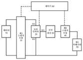
도 1은 본 개시내용의 하나의 실시예에 따른 에너지 변환 장치의 개략적인 토폴로지 구조를 도시한다. 도 1에 도시된 바와 같이, 에너지 변환 장치는 제1 스위치 모듈(10), 모터 인버터(20), 모터 권선(30), 제2 스위치 모듈(40), 제1 커패시터(50), 및 제어기(60)를 포함한다. 도 1의 파선들은 제어기(60)가 제1 스위치 모듈(10), 모터 인버터(20), 및 제2 스위치 모듈(40)로 제어 신호들을 송신하여, 제1 스위치 모듈(10), 모터 인버터(20), 및 제2 스위치 모듈(40)의 동작들을 제어한다는 것을 의미한다.FIG. 1 illustrates a schematic topological structure of an energy conversion device according to one embodiment of the present disclosure. As illustrated in FIG. 1, the energy conversion device includes a first switch module (10), a motor inverter (20), a motor winding (30), a second switch module (40), a first capacitor (50), and a controller (60). The dashed lines in FIG. 1 indicate that the controller (60) transmits control signals to the first switch module (10), the motor inverter (20), and the second switch module (40), thereby controlling operations of the first switch module (10), the motor inverter (20), and the second switch module (40).
도 1에 도시된 바와 같이, 모터 인버터(20)의 제1 버스 단자(M1)는 배터리(70)의 제1 단부와 접속되고, 모터 인버터(20)의 제2 버스 단자(M2)는 배터리(70)의 제2 단부와 접속된다. 제1 스위치 모듈(10)은 모터 인버터(20)의 제1 버스 단자(M1)와 배터리(70)의 제1 단부의 접속 및 접속해제를 제어하도록 구성되거나, 또는 제1 스위치 모듈(10)은 모터 인버터(20)의 제2 버스 단자(M2)와 배터리(70)의 제2 단부의 접속 및 접속해제를 제어하도록 구성되거나, 또는 제1 스위치 모듈(10)은 모터 인버터(20)의 제1 버스 단자(M1)와 배터리(70)의 제1 단부의 접속 및 접속해제와 모터 인버터(20)의 제2 버스 단자(M2)와 배터리(70)의 제2 단부의 접속 및 접속해제를 제어하도록 구성된다.As illustrated in FIG. 1, a first bus terminal (M1) of a motor inverter (20) is connected to a first end of a battery (70), and a second bus terminal (M2) of a motor inverter (20) is connected to a second end of a battery (70). A first switch module (10) is configured to control connection and disconnection between a first bus terminal (M1) of a motor inverter (20) and a first end of a battery (70), or a second switch module (10) is configured to control connection and disconnection between a second bus terminal (M2) of a motor inverter (20) and a second end of a battery (70), or a first switch module (10) is configured to control connection and disconnection between a first bus terminal (M1) of a motor inverter (20) and a first end of a battery (70) and connection and disconnection between a second bus terminal (M2) of a motor inverter (20) and a second end of a battery (70).
모터 권선(30)의 제1 단부는 모터 인버터(20)의 중간점 단부(M3)와 접속된다. 제2 스위치 모듈(40)과 제1 커패시터(50)는 직렬 접속된다. 직렬 접속된 제2 스위치 모듈(40) 및 제1 커패시터(50)의 제1 단부는 모터 권선(30)의 제2 단부와 접속된다. 직렬 접속된 제2 스위치 모듈(40) 및 제1 커패시터(50)의 제2 단부들은 모터 인버터(20)의 제2 버스 단자(M2)와 접속된다.The first end of the motor winding (30) is connected to the midpoint end (M3) of the motor inverter (20). The second switch module (40) and the first capacitor (50) are connected in series. The first end of the series-connected second switch module (40) and the first capacitor (50) is connected to the second end of the motor winding (30). The second ends of the series-connected second switch module (40) and the first capacitor (50) are connected to the second bus terminal (M2) of the motor inverter (20).
제어기(60)는, 축전지의 방출을 나타내는 명령에 기초하여 제1 스위치 모듈(10)이 꺼지도록 제어하여, 모터 인버터(20)로부터 배터리(70)를 접속해제하고, 제2 스위치 모듈(40)이 켜지는 경우에 제1 커패시터(50)에 저장된 에너지를 방출하도록 모터 인버터(20)를 제어하도록 구성된다.The controller (60) is configured to control the first switch module (10) to turn off based on a command indicating discharge of the battery, thereby disconnecting the battery (70) from the motor inverter (20), and to control the motor inverter (20) to discharge energy stored in the first capacitor (50) when the second switch module (40) is turned on.
전술한 에너지 변환 장치에 따르면, 제어기(60)는 제1 스위치 모듈(10)이 켜지도록, 제2 스위치 모듈(40)이 꺼지도록, 모터 인버터(20)가 켜지거나 꺼지도록 제어함으로써, 배터리(70), 제1 스위치 모듈(10), 모터 인버터(20), 및 모터 권선(30)이 모터 구동 회로를 형성하도록 한다. 제어기(60)는 제1 스위치 모듈(10)이 켜지도록, 제2 스위치 모듈(40)이 꺼지도록, 모터 인버터(20)가 켜지거나 꺼지도록 제어함으로써, 배터리(70), 제1 스위치 모듈(10), 모터 인버터(20), 모터 권선(30), 제2 스위치 모듈(40), 및 제1 커패시터(50)가 배터리 가열 회로를 형성하도록 한다. 배터리 가열 회로는, 구체적으로는 배터리 방전 회로, 모터 권선 프리휠(freewheel) 회로, 모터 권선 에너지 저장 회로 및 배터리 충전 회로를 포함하는 4개의 스테이지들을 포함한다. 배터리(70)는 모터 인버터(20)의 상부 브리지 암, 모터 권선(30), 및 제2 스위치 모듈(40)을 통해 제1 커패시터(50)로 방전하여 배터리 방전 회로를 형성한다. 모터 권선(30)은 제2 스위치 모듈(40), 제1 커패시터(50), 및 모터 인버터(20)의 하부 브리지 암을 통해 프리휠링(freewheeling)을 수행하여 모터 권선 프리휠 회로를 형성한다. 모터 권선(30)은 제1 커패시터(50)로부터의 에너지를 제2 스위치 모듈(40) 및 모터 인버터(20)의 하부 브리지 암을 통해 저장하여 모터 권선 에너지 저장 회로를 형성한다. 제1 커패시터(50)는 제2 스위치 모듈(40), 모터 권선(30), 및 모터 인버터(20)의 상부 브리지 암을 통해 배터리로 방전하여 배터리 충전 회로를 형성한다.According to the energy conversion device described above, the controller (60) controls the first switch module (10) to turn on, the second switch module (40) to turn off, and the motor inverter (20) to turn on or off, thereby causing the battery (70), the first switch module (10), the motor inverter (20), and the motor winding (30) to form a motor driving circuit. The controller (60) controls the first switch module (10) to turn on, the second switch module (40) to turn off, and the motor inverter (20) to turn on or off, thereby causing the battery (70), the first switch module (10), the motor inverter (20), the motor winding (30), the second switch module (40), and the first capacitor (50) to form a battery heating circuit. The battery heating circuit specifically includes four stages including a battery discharge circuit, a motor winding freewheel circuit, a motor winding energy storage circuit, and a battery charging circuit. The battery (70) discharges to the first capacitor (50) through the upper bridge arm of the motor inverter (20), the motor winding (30), and the second switch module (40) to form a battery discharge circuit. The motor winding (30) performs freewheeling through the second switch module (40), the first capacitor (50), and the lower bridge arm of the motor inverter (20) to form a motor winding freewheel circuit. The motor winding (30) stores energy from the first capacitor (50) through the second switch module (40) and the lower bridge arm of the motor inverter (20) to form a motor winding energy storage circuit. The first capacitor (50) discharges to the battery through the second switch module (40), the motor winding (30), and the upper bridge arm of the motor inverter (20) to form a battery charging circuit.
본 개시내용에서, 제2 스위치 모듈(40)이 켜지는 경우는 다음 중 적어도 하나를 포함한다:In the present disclosure, when the second switch module (40) is turned on, at least one of the following is included:
(1) 제2 스위치 모듈(40)을 소결하는 것. 제2 스위치 모듈(40)이 소결되는 경우, 제2 스위치 모듈(40)은 단락된 상태(short-circuited state)에 있다. 이러한 경우, 제2 스위치 모듈(40)은 전도성인 것으로 간주된다.(1) Sintering the second switch module (40). When the second switch module (40) is sintered, the second switch module (40) is in a short-circuited state. In this case, the second switch module (40) is considered to be conductive.
(2) 본 개시내용의 실시예들에서 에너지 변환 장치를 통해 외부 장치가 배터리(70)를 충전한 후, 제2 스위치 모듈(40)은 소결되지 않고, 제2 스위치 모듈(40)은 축전지의 방출을 나타내는 명령에 기초하여 켜지도록 제어된다(본 개시내용의 실시예들에서 에너지 변환 장치를 통해 외부 장치가 배터리(70)를 충전한 후, 일부 에너지가 여전히 제1 커패시터(50)에 남아 있고, 안전을 위해, 제1 커패시터(50)에 저장된 에너지는 방출될 필요가 있다). 이러한 경우, 제2 스위치 모듈(40)은 소결되지 않기 때문에, 제2 스위치 모듈의 스위칭은 여전히 제어기(60)에 의해 제어될 수 있다. 그러나, 제1 커패시터(50)에 저장된 에너지가 방출될 필요가 있는 경우, 에너지 방출 회로가 접속될 수 있도록 제2 스위치 모듈(40)이 전도 상태에 있을 필요가 있다. 따라서, 이러한 경우, 축전지의 방출을 나타내는 명령에 기초하여 제2 스위치 모듈(40)이 켜지도록 제어할 필요가 있다.(2) In embodiments of the present disclosure, after the external device charges the battery (70) via the energy conversion device, the second switch module (40) is not sintered, and the second switch module (40) is controlled to turn on based on a command indicating the discharge of the battery (in embodiments of the present disclosure, after the external device charges the battery (70) via the energy conversion device, some energy still remains in the first capacitor (50), and for safety, the energy stored in the first capacitor (50) needs to be discharged). In this case, since the second switch module (40) is not sintered, the switching of the second switch module can still be controlled by the controller (60). However, when the energy stored in the first capacitor (50) needs to be discharged, the second switch module (40) needs to be in a conducting state so that the energy discharge circuit can be connected. Therefore, in this case, it is necessary to control the second switch module (40) to turn on based on a command indicating the discharge of the battery.
(3) 본 개시내용의 실시예들에서 에너지 변환 장치를 통한 배터리(70)의 자체 가열이 수행된 후, 제2 스위치 모듈(40)은 소결되지 않고, 제2 스위치 모듈(40)은 축전지의 방출을 나타내는 명령에 기초하여 켜지도록 제어된다(본 개시내용의 실시예들에서 에너지 변환 장치를 통해 배터리(70)의 자체 가열이 수행된 후, 일부 에너지가 여전히 제1 커패시터(50)에 남아 있고, 안전을 위해, 제1 커패시터(50)에 저장된 에너지는 방출될 필요가 있다). 이러한 경우, 제2 스위치 모듈(40)은 소결되지 않기 때문에, 제2 스위치 모듈의 스위칭은 여전히 제어기(60)에 의해 제어될 수 있다. 그러나, 제1 커패시터(50)에 저장된 에너지가 방출될 필요가 있는 경우, 에너지 방출 회로가 접속될 수 있도록 제2 스위치 모듈(40)이 전도 상태에 있을 필요가 있다. 따라서, 이러한 경우, 축전지의 방출을 나타내는 명령에 기초하여 제2 스위치 모듈(40)을 켜는 것이 필요하다.(3) In the embodiments of the present disclosure, after self-heating of the battery (70) is performed via the energy conversion device, the second switch module (40) is not sintered, and the second switch module (40) is controlled to turn on based on a command indicating discharge of the battery (in the embodiments of the present disclosure, after self-heating of the battery (70) is performed via the energy conversion device, some energy still remains in the first capacitor (50), and for safety, the energy stored in the first capacitor (50) needs to be discharged). In this case, since the second switch module (40) is not sintered, the switching of the second switch module can still be controlled by the controller (60). However, when the energy stored in the first capacitor (50) needs to be discharged, the second switch module (40) needs to be in a conducting state so that the energy discharge circuit can be connected. Therefore, in this case, it is necessary to turn on the second switch module (40) based on a command indicating discharge of the battery.
(4) 본 개시내용의 실시예들에서 에너지 변환 장치를 통해 구동 기능이 실현된 후, 제2 스위치 모듈(40)은 소결되지 않고, 제2 스위치 모듈(40)은 축전지의 방출을 나타내는 명령에 기초하여 켜지도록 제어된다(본 개시내용의 실시예들에서 에너지 변환 장치를 통해 구동 기능이 실현된 후, 일부 에너지는 여전히 제2 커패시터에 남아 있고, 안전을 위해, 제2 커패시터에 저장된 에너지는 방출될 필요가 있다). 이러한 경우, 제2 스위치 모듈(40)은 소결되지 않기 때문에, 제2 스위치 모듈의 스위칭은 여전히 제어기(60)에 의해 제어될 수 있다. 그러나, 제1 커패시터(50)에 저장된 에너지가 방출될 필요가 있는 경우, 에너지 방출 회로가 접속될 수 있도록 제2 스위치 모듈(40)이 전도 상태에 있을 필요가 있다. 따라서, 이러한 경우, 축전지의 방출을 나타내는 명령에 기초하여 제2 스위치 모듈(40)을 켜는 것이 필요하다.(4) In the embodiments of the present disclosure, after the driving function is realized through the energy conversion device, the second switch module (40) is not sintered, and the second switch module (40) is controlled to be turned on based on a command indicating the discharge of the storage battery (in the embodiments of the present disclosure, after the driving function is realized through the energy conversion device, some energy still remains in the second capacitor, and for safety, the energy stored in the second capacitor needs to be discharged). In this case, since the second switch module (40) is not sintered, the switching of the second switch module can still be controlled by the controller (60). However, when the energy stored in the first capacitor (50) needs to be discharged, the second switch module (40) needs to be in a conducting state so that the energy discharge circuit can be connected. Therefore, in this case, it is necessary to turn on the second switch module (40) based on a command indicating the discharge of the storage battery.
전술한 기술적 해결책들은 다음의 유익한 효과들을 갖는다.The above-described technical solutions have the following beneficial effects:
(1) 본 개시내용에서의 에너지 변환 장치는 제2 스위치 모듈(40)이 꺼지도록 제어함으로써 모터 구동 기능을 실현할 수 있고, 제2 스위치 모듈(40)이 켜지도록 제어함으로써 배터리 가열 기능을 실현할 수 있다.(1) The energy conversion device in the present disclosure can realize a motor driving function by controlling the second switch module (40) to be turned off, and can realize a battery heating function by controlling the second switch module (40) to be turned on.
(2) 제1 커패시터(50)의 에너지 방출이 에너지 변환 장치의 컴포넌트들 사이의 연결을 통해 실현될 수 있기 때문에, 부가적인 컴포넌트들이 요구되지 않고, 이는 전체 차량의 비용을 감소시킬 수 있다.(2) Since the energy release of the first capacitor (50) can be realized through the connection between components of the energy conversion device, additional components are not required, which can reduce the cost of the entire vehicle.
(3) 제1 스위치 모듈(10)이 모터 인버터(20)로부터 배터리(70)를 접속해제하고 제2 스위치 모듈(40)이 전도 상태에 있는 경우에, 모터 인버터(20)가 제1 커패시터(50)에 저장된 에너지를 방출하도록 제어되기 때문에, 다음의 이점들이 실현된다. 한편으로는, 제1 커패시터(50)의 에너지 방출 동안 배터리(70)에 의해 야기되는 고전압 안전 문제가 해결된다. 반면에, 도 1의 토폴로지로부터, 에너지 방출 동안, 제1 스위치 모듈(10)은 꺼진 상태에 있고 제2 스위치 모듈(40)은 전도 상태에 있다는 것을 알 수 있다. 따라서, 제1 커패시터(50)에 저장된 에너지는 모터 인버터(20), 모터 권선(30), 제2 스위치 모듈(40), 및 제1 커패시터(50)로 구성된 순환 루프에 의해 방출된다. 즉, 모터 인버터(20)의 반복된 스위칭에 의해 야기되는 에너지 손실들, 전도 상태에서 모터 인버터(20)에 의해 발생하는 에너지 소모, 및 모터 권선(30) 상의 열 손실들은 제1 커패시터(50) 상에서 고전압 에너지의 소모를 실현하고, 그에 의해 제1 커패시터(50)의 에너지 방출을 실현한다. 이에 더해, 방출 동안의 방출 전류가 매우 크지 않기 때문에, 제2 스위치 모듈(40)에 의해 야기되는 불완전 소결 또는 소프트웨어 버그들에 의해 야기되는 제2 스위치 모듈(40)의 거짓 소결이, 제2 스위치 모듈(40)의 참 소결로 바뀌는 것이 방지되고, 그에 의해 제2 스위치 모듈(40)에 대한 2차 손상을 방지한다.(3) Since the motor inverter (20) is controlled to release the energy stored in the first capacitor (50) when the first switch module (10) disconnects the battery (70) from the motor inverter (20) and the second switch module (40) is in a conducting state, the following advantages are realized. On the one hand, the high voltage safety problem caused by the battery (70) during the energy release of the first capacitor (50) is solved. On the other hand, from the topology of Fig. 1, it can be seen that during the energy release, the first switch module (10) is in a turned-off state and the second switch module (40) is in a conducting state. Therefore, the energy stored in the first capacitor (50) is released by the circulation loop composed of the motor inverter (20), the motor winding (30), the second switch module (40), and the first capacitor (50). That is, the energy losses caused by repeated switching of the motor inverter (20), the energy consumption caused by the motor inverter (20) in the conduction state, and the heat losses on the motor winding (30) realize the consumption of high-voltage energy on the first capacitor (50), thereby realizing the energy release of the first capacitor (50). In addition, since the release current during release is not very large, the false sintering of the second switch module (40) caused by incomplete sintering or software bugs caused by the second switch module (40) is prevented from changing into true sintering of the second switch module (40), thereby preventing secondary damage to the second switch module (40).
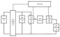
도 2는 본 개시내용의 하나의 실시예에 따른 에너지 변환 장치의 다른 개략적인 토폴로지 구조를 도시한다. 도 2에 도시된 바와 같이, 에너지 변환 장치는 제2 커패시터(80)를 추가로 포함한다. 제2 커패시터(80)의 제1 단부는 모터 인버터(20)의 제1 버스 단자(M1)와 접속된다. 제2 커패시터(80)의 제2 단부는 모터 인버터(20)의 제2 버스 단자(M2)와 접속된다.FIG. 2 illustrates another schematic topological structure of an energy conversion device according to one embodiment of the present disclosure. As illustrated in FIG. 2, the energy conversion device further includes a second capacitor (80). A first end of the second capacitor (80) is connected to a first bus terminal (M1) of the motor inverter (20). A second end of the second capacitor (80) is connected to a second bus terminal (M2) of the motor inverter (20).
제어기(60)는, 축전지의 방출을 나타내는 명령에 기초하여 제1 스위치 모듈(10)이 꺼지도록 제어하여, 제2 커패시터(80) 및 모터 인버터(20)로부터 배터리(70)를 접속해제하고, 제2 스위치 모듈(40)이 켜지는 경우에 제1 커패시터(50)에 저장된 에너지 및 제2 커패시터(80)에 저장된 에너지를 방출하도록 모터 인버터(20)를 제어하도록 추가로 구성된다. 제2 커패시터(80)에 저장된 에너지를 방출하는 이유는, 본 개시내용의 실시예들에서 에너지 변환 장치를 통한 배터리(70)의 충전, 배터리(70)의 자체 가열, 및 구동 기능이 실현된 후 고전압 에너지가 제2 커패시터(80)에 남아 있기 때문이다. 안전을 위해, 제2 커패시터(80)에 저장된 에너지를 방출할 필요가 있다.The controller (60) is further configured to control the first switch module (10) to be turned off based on a command indicating discharge of the battery, thereby disconnecting the battery (70) from the second capacitor (80) and the motor inverter (20), and to control the motor inverter (20) to discharge the energy stored in the first capacitor (50) and the energy stored in the second capacitor (80) when the second switch module (40) is turned on. The reason for releasing the energy stored in the second capacitor (80) is that, in embodiments of the present disclosure, after the charging of the battery (70), self-heating of the battery (70), and driving function are realized through the energy conversion device, high-voltage energy remains in the second capacitor (80). For safety, it is necessary to release the energy stored in the second capacitor (80).
제2 커패시터(80)의 에너지 방출 또한 에너지 변환 장치의 컴포넌트들 사이의 연결을 통해 실현되기 때문에, 부가적인 컴포넌트들이 요구되지 않고, 이는 전체 차량의 비용을 감소시킬 수 있다. 이에 더해, 제2 커패시터(80)의 에너지 방출의 원리는 위에서 설명된 제1 커패시터(50)의 에너지 방출의 원리와 유사하고, 즉, 에너지 방출은 모터 인버터(20)의 반복된 스위칭에 의해 야기되는 에너지 손실들, 전도 상태에서 모터 인버터(20)에 의해 발생되는 에너지 소모, 및 모터 권선(30) 상의 열 손실들을 통해 실현된다. 따라서, 방출 동안의 방출 전류가 크지 않으므로, 제2 스위치 모듈(40)에 의해 야기되는 불완전 소결 또는 소프트웨어 버그들에 의해 야기되는 제2 스위치 모듈(40)의 거짓 소결이, 제2 스위치 모듈(40)의 참 소결로 바뀌는 것이 방지되고, 그에 의해 제2 스위치 모듈(40)에 대한 2차 손상을 방지한다.Since the energy release of the second capacitor (80) is also realized through the connection between the components of the energy conversion device, no additional components are required, which can reduce the cost of the entire vehicle. In addition, the principle of the energy release of the second capacitor (80) is similar to the principle of the energy release of the first capacitor (50) described above, that is, the energy release is realized through energy losses caused by repeated switching of the motor inverter (20), energy consumption generated by the motor inverter (20) in a conducting state, and heat losses on the motor winding (30). Therefore, since the release current during the release is not large, false sintering of the second switch module (40) caused by incomplete sintering or software bugs caused by the second switch module (40) is prevented from changing into true sintering of the second switch module (40), thereby preventing secondary damage to the second switch module (40).
도 3은 본 개시내용의 하나의 실시예에 따른 에너지 변환 장치의 개략적인 회로도이다. 도 3에 도시된 바와 같이, 모터 인버터(20)는 N상 브리지 암들을 포함하고, 모터 권선(30)은 N개의 권선들을 포함한다. N개의 권선들의 제1 단부들은 각각 N상 브리지 암들의 중간점 단부들(즉, 도 3에서 A, B 및 C로 도시된 포지션들)과 일대일 대응으로 접속된다. N≥1.FIG. 3 is a schematic circuit diagram of an energy conversion device according to one embodiment of the present disclosure. As shown in FIG. 3, a motor inverter (20) includes N-phase bridge arms, and a motor winding (30) includes N windings. First ends of the N windings are respectively connected to midpoint ends of the N-phase bridge arms (i.e., positions indicated by A, B, and C in FIG. 3) in a one-to-one correspondence. N≥1.
여전히 도 3을 참조하면, 제1 스위치 모듈(10)은 배터리(70)의 제1 단부와 모터 인버터(20)의 제1 버스 단자 사이에 접속된 양의 접촉기(K1)를 포함하고, 배터리(70)의 제2 단부와 모터 인버터(20)의 제2 버스 단자 사이에 접속된 음의 접촉기(K2)를 추가로 포함한다. 양의 접촉기(K1)는 모터 인버터(20)의 제1 버스 단자로부터 배터리(70)의 제1 단부를 접속해제하도록 구성될 수 있고, 그에 의해 모터 인버터로부터 배터리(70)를 접속해제한다. 음의 접촉기(K2)는 모터 인버터(20)의 제2 버스 단자로부터 배터리(70)의 제2 단부를 접속해제하도록 구성될 수 있고, 그에 의해 모터 인버터로부터 배터리(70)를 접속해제한다. 본 기술분야의 통상의 기술자는 제1 스위치 모듈(10)이 오직 양의 접촉기(K1)만을, 또는 오직 음의 접촉기(K2)만을, 또는 양의 접촉기(K1) 및 음의 접촉기(K2) 둘 다를 포함할 수 있다는 것을 이해할 수 있다.Still referring to FIG. 3, the first switch module (10) includes a positive contactor (K1) connected between a first end of the battery (70) and a first bus terminal of the motor inverter (20), and further includes a negative contactor (K2) connected between a second end of the battery (70) and a second bus terminal of the motor inverter (20). The positive contactor (K1) may be configured to disconnect the first end of the battery (70) from the first bus terminal of the motor inverter (20), thereby disconnecting the battery (70) from the motor inverter. The negative contactor (K2) may be configured to disconnect the second end of the battery (70) from the second bus terminal of the motor inverter (20), thereby disconnecting the battery (70) from the motor inverter. A person skilled in the art will appreciate that the first switch module (10) may include only a positive contactor (K1), only a negative contactor (K2), or both a positive contactor (K1) and a negative contactor (K2).
이에 더해, 본 기술분야의 통상의 기술자는 도 3에 도시된 모터 인버터(20)의 특정 구조, 모터 권선(30)의 특정 구조, 및 제1 스위치 모듈(10)의 특정 구조는 단지 예들에 불과하고, 이는 본 개시내용에서 제한되지 않는다는 것을 추가로 이해해야 한다.In addition, a person skilled in the art should further understand that the specific structure of the motor inverter (20), the specific structure of the motor winding (30), and the specific structure of the first switch module (10) illustrated in FIG. 3 are merely examples and are not limited to the present disclosure.
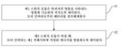
도 4는 본 개시내용의 하나의 실시예에 따른 에너지 변환 장치를 위한 안전 제어 방법의 흐름도이다. 방법은 도 1 내지 도 3에 도시된 에너지 변환 장치에 저장된 에너지를 방출하는 데에 사용될 수 있다. 도 4에 도시된 바와 같이, 방법은 다음의 단계들 S41 내지 S42를 포함한다.FIG. 4 is a flowchart of a safety control method for an energy conversion device according to one embodiment of the present disclosure. The method can be used to release energy stored in the energy conversion device illustrated in FIGS. 1 to 3. As illustrated in FIG. 4, the method includes the following steps S41 to S42.
단계 S41: 제1 스위치 모듈(10)은 축전지의 방출을 나타내는 명령에 기초하여 꺼지도록 제어되어, 모터 인버터(20)로부터 배터리(70)를 접속해제한다.Step S41: The first switch module (10) is controlled to turn off based on a command indicating discharge of the battery, thereby disconnecting the battery (70) from the motor inverter (20).
단계 S42: 제2 스위치 모듈(40)이 켜지는 경우, 모터 인버터(20)는 제1 커패시터(50)에 저장된 에너지를 방출하도록 제어된다.Step S42: When the second switch module (40) is turned on, the motor inverter (20) is controlled to release the energy stored in the first capacitor (50).
본 개시내용에서, 제2 스위치 모듈(40)이 켜지는 경우는 다음 중 적어도 하나를 포함한다:In the present disclosure, when the second switch module (40) is turned on, at least one of the following is included:
(1) 제2 스위치 모듈(40)의 소결. 제2 스위치 모듈(40)이 소결되는 경우, 제2 스위치 모듈(40)은 단락된 상태에 있다. 이러한 경우, 제2 스위치 모듈(40)이 켜져있는 것으로 간주된다.(1) Sintering of the second switch module (40). When the second switch module (40) is sintered, the second switch module (40) is in a short-circuited state. In this case, the second switch module (40) is considered to be turned on.
(2) 본 개시내용의 실시예들에서 에너지 변환 장치를 통해 외부 장치가 배터리(70)를 충전한 후, 제2 스위치 모듈(40)은 소결되지 않고, 제2 스위치 모듈(40)은 축전지의 방출을 나타내는 명령에 기초하여 켜지도록 제어된다(본 개시내용의 실시예들에서 에너지 변환 장치를 통해 외부 장치가 배터리(70)를 충전한 후, 일부 에너지가 여전히 제1 커패시터(50)에 남아 있고, 안전을 위해, 제1 커패시터(50)에 저장된 에너지는 방출될 필요가 있다). 이러한 경우, 제2 스위치 모듈(40)은 소결되지 않기 때문에, 제2 스위치 모듈의 스위칭은 여전히 제어될 수 있다. 그러나, 제1 커패시터(50)에 저장된 에너지가 방출될 필요가 있는 경우, 에너지 방출 회로가 접속될 수 있도록 제2 스위치 모듈(40)이 전도 상태에 있을 필요가 있다. 따라서, 이러한 경우, 축전지의 방출을 나타내는 명령에 기초하여 제2 스위치 모듈(40)이 켜지도록 제어할 필요가 있다.(2) In embodiments of the present disclosure, after the external device charges the battery (70) via the energy conversion device, the second switch module (40) is not sintered, and the second switch module (40) is controlled to turn on based on a command indicating the discharge of the battery (in embodiments of the present disclosure, after the external device charges the battery (70) via the energy conversion device, some energy still remains in the first capacitor (50), and for safety, the energy stored in the first capacitor (50) needs to be discharged). In this case, since the second switch module (40) is not sintered, the switching of the second switch module can still be controlled. However, when the energy stored in the first capacitor (50) needs to be discharged, the second switch module (40) needs to be in a conducting state so that the energy discharge circuit can be connected. Therefore, in this case, it is necessary to control the second switch module (40) to turn on based on a command indicating the discharge of the battery.
(3) 본 개시내용의 실시예들에서 에너지 변환 장치를 통한 배터리(70)의 자체 가열이 수행된 후, 제2 스위치 모듈(40)은 소결되지 않고, 제2 스위치 모듈(40)은 축전지의 방출을 나타내는 명령에 기초하여 켜지도록 제어된다(본 개시내용의 실시예들에서 에너지 변환 장치를 통해 배터리(70)의 자체 가열이 수행된 후, 일부 에너지가 여전히 제1 커패시터(50)에 남아 있고, 안전을 위해, 제1 커패시터(50)에 저장된 에너지는 방출될 필요가 있다). 이러한 경우, 제2 스위치 모듈(40)은 소결되지 않기 때문에, 제2 스위치 모듈의 스위칭은 여전히 제어될 수 있다. 그러나, 제1 커패시터(50)에 저장된 에너지가 방출될 필요가 있는 경우, 에너지 방출 회로가 접속될 수 있도록 제2 스위치 모듈(40)이 전도 상태에 있을 필요가 있다. 따라서, 이러한 경우, 축전지의 방출을 나타내는 명령에 기초하여 제2 스위치 모듈(40)이 켜지도록 제어할 필요가 있다.(3) In the embodiments of the present disclosure, after self-heating of the battery (70) is performed via the energy conversion device, the second switch module (40) is not sintered, and the second switch module (40) is controlled to turn on based on a command indicating discharge of the battery (in the embodiments of the present disclosure, after self-heating of the battery (70) is performed via the energy conversion device, some energy still remains in the first capacitor (50), and for safety, the energy stored in the first capacitor (50) needs to be discharged). In this case, since the second switch module (40) is not sintered, the switching of the second switch module can still be controlled. However, when the energy stored in the first capacitor (50) needs to be discharged, the second switch module (40) needs to be in a conducting state so that the energy discharge circuit can be connected. Therefore, in this case, it is necessary to control the second switch module (40) to turn on based on a command indicating discharge of the battery.
(4) 본 개시내용의 실시예들에서 에너지 변환 장치를 통해 구동 기능이 실현된 후, 제2 스위치 모듈(40)은 소결되지 않고, 제2 스위치 모듈(40)은 축전지의 방출을 나타내는 명령에 기초하여 켜지도록 제어된다(본 개시내용의 실시예들에서 에너지 변환 장치를 통해 구동 기능이 실현된 후, 일부 에너지는 여전히 제2 커패시터에 남아 있고, 안전을 위해, 제2 커패시터에 저장된 에너지는 방출될 필요가 있다). 이러한 경우, 제2 스위치 모듈(40)은 소결되지 않기 때문에, 제2 스위치 모듈의 스위칭은 여전히 제어될 수 있다. 그러나, 제1 커패시터(50)에 저장된 에너지가 방출될 필요가 있는 경우, 에너지 방출 회로가 접속될 수 있도록 제2 스위치 모듈(40)이 전도 상태에 있을 필요가 있다. 따라서, 이러한 경우, 축전지의 방출을 나타내는 명령에 기초하여 제2 스위치 모듈(40)이 켜지도록 제어할 필요가 있다.(4) In the embodiments of the present disclosure, after the driving function is realized through the energy conversion device, the second switch module (40) is not sintered, and the second switch module (40) is controlled to turn on based on a command indicating the discharge of the storage battery (in the embodiments of the present disclosure, after the driving function is realized through the energy conversion device, some energy still remains in the second capacitor, and for safety, the energy stored in the second capacitor needs to be discharged). In this case, since the second switch module (40) is not sintered, the switching of the second switch module can still be controlled. However, when the energy stored in the first capacitor (50) needs to be discharged, the second switch module (40) needs to be in a conducting state so that the energy discharge circuit can be connected. Therefore, in this case, it is necessary to control the second switch module (40) to turn on based on a command indicating the discharge of the storage battery.
전술한 기술적 해결책들은 다음의 유익한 효과들을 갖는다:The above-described technical solutions have the following beneficial effects:
(1) 제1 커패시터(50)의 에너지 방출이 에너지 변환 장치의 컴포넌트들 사이의 연결을 통해 실현될 수 있기 때문에, 부가적인 컴포넌트들이 요구되지 않고, 이는 전체 차량의 비용을 감소시킬 수 있다.(1) Since the energy release of the first capacitor (50) can be realized through the connection between components of the energy conversion device, additional components are not required, which can reduce the cost of the entire vehicle.
(2) 제1 스위치 모듈(10)이 모터 인버터(20)로부터 배터리(70)를 접속해제하고 제2 스위치 모듈(40)이 전도 상태에 있는 경우에, 모터 인버터(20)가 제1 커패시터(50)에 저장된 에너지를 방출하도록 제어되기 때문에, 다음의 이점들이 실현된다. 한편으로는, 제1 커패시터(50)의 에너지 방출 동안 배터리(70)에 의해 야기되는 고전압 안전 문제가 해결된다. 반면에, 도 1의 토폴로지로부터, 에너지 방출 동안, 제1 스위치 모듈(10)은 꺼진 상태에 있고 제2 스위치 모듈(40)은 전도 상태에 있다는 것을 알 수 있다. 따라서, 제1 커패시터(50)에 저장된 에너지는 모터 인버터(20), 모터 권선(30), 제2 스위치 모듈(40), 및 제1 커패시터(50)로 구성된 순환 루프에 의해 방출된다. 즉, 모터 인버터(20)의 반복된 스위칭에 의해 야기되는 에너지 손실들, 전도 상태에서 모터 인버터(20)에 의해 발생하는 에너지 소모, 및 모터 권선(30) 상의 열 손실들은 제1 커패시터(50) 상에서 고전압 에너지의 소모를 실현하고, 그에 의해 제1 커패시터(50)의 에너지 방출을 실현한다. 이에 더해, 방출 동안의 방출 전류가 매우 크지 않기 때문에, 제2 스위치 모듈(40)에 의해 야기되는 불완전 소결 또는 소프트웨어 버그들에 의해 야기되는 제2 스위치 모듈(40)의 거짓 소결이, 제2 스위치 모듈(40)의 참 소결로 바뀌는 것이 방지되고, 그에 의해 제2 스위치 모듈(40)에 대한 2차 손상을 방지한다.(2) Since the motor inverter (20) is controlled to release the energy stored in the first capacitor (50) when the first switch module (10) disconnects the battery (70) from the motor inverter (20) and the second switch module (40) is in a conducting state, the following advantages are realized. On the one hand, the high voltage safety problem caused by the battery (70) during the energy release of the first capacitor (50) is solved. On the other hand, from the topology of FIG. 1, it can be seen that during the energy release, the first switch module (10) is in a turned-off state and the second switch module (40) is in a conducting state. Therefore, the energy stored in the first capacitor (50) is released by the circulation loop composed of the motor inverter (20), the motor winding (30), the second switch module (40), and the first capacitor (50). That is, the energy losses caused by repeated switching of the motor inverter (20), the energy consumption caused by the motor inverter (20) in the conduction state, and the heat losses on the motor winding (30) realize the consumption of high-voltage energy on the first capacitor (50), thereby realizing the energy release of the first capacitor (50). In addition, since the release current during release is not very large, the false sintering of the second switch module (40) caused by incomplete sintering or software bugs caused by the second switch module (40) is prevented from changing into true sintering of the second switch module (40), thereby preventing secondary damage to the second switch module (40).
도 5는 본 개시내용의 하나의 실시예에 따른 에너지 변환 장치를 위한 안전 제어 방법의 다른 흐름도이다. 프로세스는 도 2에 도시된 에너지 변환 장치에 저장된 에너지를 방출하는 데에 사용될 수 있다. 도 5에 도시된 바와 같이, 방법은 다음의 단계들 S51 내지 S52를 포함한다.FIG. 5 is another flowchart of a safety control method for an energy conversion device according to one embodiment of the present disclosure. The process can be used to release energy stored in the energy conversion device illustrated in FIG. 2. As illustrated in FIG. 5, the method includes the following steps S51 to S52.
단계 S51: 제1 스위치 모듈(10)은 축전지의 방출을 나타내는 명령에 기초하여 꺼지도록 제어되어, 제2 커패시터(80) 및 모터 인버터(20)로부터 배터리(70)를 접속해제한다.Step S51: The first switch module (10) is controlled to turn off based on a command indicating discharge of the battery, thereby disconnecting the battery (70) from the second capacitor (80) and the motor inverter (20).
단계 S52: 제2 스위치 모듈(40)이 켜지는 경우, 모터 인버터(20)는 제1 커패시터(50)에 저장된 에너지 및 제2 커패시터(80)에 저장된 에너지를 방출하도록 제어된다.Step S52: When the second switch module (40) is turned on, the motor inverter (20) is controlled to release the energy stored in the first capacitor (50) and the energy stored in the second capacitor (80).
제2 스위치 모듈(40)이 켜지는 경우는 전술되었으므로, 본 명세서에서 반복되지 않는다.The case where the second switch module (40) is turned on has been described above and is not repeated in this specification.
이에 더해, 단계 S52는 다음의 단계들을 포함할 수 있다.In addition, step S52 may include the following steps:
단계 S52a: 모터 인버터(20)는 제1 커패시터(50)에 저장된 에너지를 방출하도록 제어된다.Step S52a: The motor inverter (20) is controlled to release energy stored in the first capacitor (50).
단계 S52b: 모터 인버터(20)는 제1 커패시터(50)를 통해 제2 커패시터(80)에 저장된 에너지를 방출하도록 제어된다.Step S52b: The motor inverter (20) is controlled to release energy stored in the second capacitor (80) through the first capacitor (50).
예를 들어, 첫째로, 모터 인버터(20)의 상부 브리지 암이 켜지도록 제어함으로써, 제2 커패시터(80)가 제1 커패시터(50)를 충전하도록 한다. 그 후, 모터 인버터(20)의 상부 브리지 암은 꺼진 채로 유지되도록 제어되고, 모터 인버터(20)의 하부 브리지 암은 교대로 켜지거나 꺼지도록 제어되어, 충전된 제1 커패시터(50)에 저장된 에너지를 방출한다. 제2 커패시터(80)의 전압이 미리 설정된 전압(예를 들어, 60V 또는 다른 미리 설정된 값들)보다 더 낮을 때까지, 모터 인버터(20)의 상부 브리지 암이 켜지도록 제어하는 단계 및 상부 브리지 암이 꺼진 채로 유지하고 모터 인버터(20)의 하부 브리지 암이 교대로 켜지거나 꺼지도록 제어하는 단계가 반복된다. 이러한 방식으로, 제2 커패시터(80)의 에너지 방출이 실현된다.For example, first, the upper bridge arm of the motor inverter (20) is controlled to turn on, thereby causing the second capacitor (80) to charge the first capacitor (50). Thereafter, the upper bridge arm of the motor inverter (20) is controlled to remain off, and the lower bridge arm of the motor inverter (20) is controlled to alternately turn on or off, thereby releasing the energy stored in the charged first capacitor (50). The step of controlling the upper bridge arm of the motor inverter (20) to turn on and the step of keeping the upper bridge arm off and controlling the lower bridge arm of the motor inverter (20) to alternately turn on or off are repeated until the voltage of the second capacitor (80) is lower than a preset voltage (e.g., 60 V or other preset values). In this manner, the energy release of the second capacitor (80) is realized.
모터 인버터(20)가 다수의 브리지 암들을 포함하는 경우, 본 개시내용에서의 하부 브리지 암이 교대로 켜지거나 꺼지는 것은 적어도 하나의 하부 브리지 암이 교대로 켜지거나 꺼지는 것을 의미한다. 다수의 하부 브리지 암들이 교대로 켜지거나 꺼지도록 제어되어 방출 전류의 크기를 제어하도록 제어되고, 그에 의해 방출 동안 제2 스위치 모듈(40)에 대한 2차 손상을 회피한다.When the motor inverter (20) includes a plurality of bridge arms, the lower bridge arms being alternately turned on or off in the present disclosure means that at least one lower bridge arm is alternately turned on or off. The plurality of lower bridge arms are controlled to be alternately turned on or off to control the size of the emission current, thereby avoiding secondary damage to the second switch module (40) during emission.
제2 커패시터(80)가 제1 커패시터(50)를 충전하는 시간은 차량 타입, 제1 커패시터(50)의 커패시턴스 값, 및 제2 커패시터(80)의 커패시턴스 값에 따라 교정될 수 있다. 예를 들어, 시간은 250 ms, 100 ms, 또는 다른 값들일 수 있다.The time for the second capacitor (80) to charge the first capacitor (50) can be calibrated depending on the vehicle type, the capacitance value of the first capacitor (50), and the capacitance value of the second capacitor (80). For example, the time can be 250 ms, 100 ms, or other values.
단계 S52에서, 제1 커패시터(50)에 저장된 에너지가 먼저 방출되고, 그 후 제2 커패시터(80)에 저장된 에너지가 제1 커패시터(50)를 통해 방출되고, 이는 제1 커패시터(50)가 모터 인버터(20)의 제어불가능한 다이오드를 통해 제2 커패시터(80)와 임펄스 전류를 형성하는 것을 방지할 수 있고, 그에 의해 방출 동안 제2 스위치 모듈(40)에 대한 손상을 회피할 수 있다.In step S52, the energy stored in the first capacitor (50) is first released, and then the energy stored in the second capacitor (80) is released through the first capacitor (50), which can prevent the first capacitor (50) from forming an impulse current with the second capacitor (80) through the uncontrollable diode of the motor inverter (20), thereby avoiding damage to the second switch module (40) during the release.
전술한 기술적 해결책에 따르면, 제2 커패시터(80)의 에너지 방출 또한 에너지 변환 장치의 컴포넌트들 사이의 연결을 통해 실현되기 때문에, 부가적인 컴포넌트들이 요구되지 않고, 이는 전체 차량의 비용을 감소시킬 수 있다. 이에 더해, 제2 커패시터(80)의 에너지 방출의 원리는 전술된 제1 커패시터(50)의 에너지 방출의 원리와 유사하고, 즉, 에너지 방출은 모터 인버터(20)의 반복된 스위칭에 의해 야기되는 에너지 손실들, 전도 상태에서 모터 인버터(20)에 의해 발생되는 에너지 소모, 및 모터 권선(30) 상의 열 손실들을 통해 실현된다. 따라서, 방출 동안의 방출 전류가 크지 않으므로, 제2 스위치 모듈(40)에 의해 야기되는 불완전 소결 또는 소프트웨어 버그들에 의해 야기되는 제2 스위치 모듈(40)의 거짓 소결이, 제2 스위치 모듈(40)의 참 소결로 바뀌는 것이 방지되고, 그에 의해 제2 스위치 모듈(40)에 대한 2차 손상을 방지한다.According to the above-described technical solution, since the energy release of the second capacitor (80) is also realized through the connection between the components of the energy conversion device, no additional components are required, which can reduce the cost of the entire vehicle. In addition, the principle of the energy release of the second capacitor (80) is similar to the principle of the energy release of the first capacitor (50) described above, that is, the energy release is realized through energy losses caused by repeated switching of the motor inverter (20), energy consumption generated by the motor inverter (20) in the conducting state, and heat losses on the motor winding (30). Therefore, since the release current during the release is not large, false sintering of the second switch module (40) caused by incomplete sintering or software bugs caused by the second switch module (40) is prevented from changing into true sintering of the second switch module (40), thereby preventing secondary damage to the second switch module (40).
하나의 실시예에서, 단계들 S42 및 S52a에서 제1 커패시터(50)에 저장된 에너지를 방출하기 위한 모터 인버터(20)의 제어는 다음을 포함할 수 있다: 모터 인버터(20)의 상부 브리지 암이 꺼진 채로 유지되도록 제어하고, 모터 인버터(20)의 하부 브리지 암은 교대로 켜지거나 꺼지도록 제어하여, 제1 커패시터(50)에 저장된 에너지를 방출한다.In one embodiment, the control of the motor inverter (20) to release the energy stored in the first capacitor (50) in steps S42 and S52a may include: controlling the upper bridge arm of the motor inverter (20) to remain off, and controlling the lower bridge arm of the motor inverter (20) to alternately turn on and off, thereby releasing the energy stored in the first capacitor (50).
기술적 해결책에 따르면, 제1 커패시터(50) 상에서 고전압 에너지의 소모는 모터 인버터(20)의 하부 브리지 암의 반복된 스위칭에 의해 야기되는 에너지 손실들, 전도 상태에서 모터 인버터(20)의 하부 브리지 암에 의해 발생하는 에너지 소모, 및 모터 권선(30) 상의 열 손실들을 통해 실현될 수 있고, 그에 의해 제1 커패시터(50)의 에너지 방출을 실현한다. 이에 더해, 방출 동안의 방출 전류가 매우 크지 않기 때문에, 제2 스위치 모듈(40)에 의해 야기되는 불완전 소결 또는 소프트웨어 버그들에 의해 야기되는 제2 스위치 모듈(40)의 거짓 소결이, 제2 스위치 모듈(40)의 참 소결로 바뀌는 것이 방지되고, 그에 의해 제2 스위치 모듈(40)에 대한 2차 손상을 방지한다.According to the technical solution, the dissipation of high voltage energy on the first capacitor (50) can be realized through energy losses caused by repeated switching of the lower bridge arm of the motor inverter (20), energy dissipation caused by the lower bridge arm of the motor inverter (20) in the conducting state, and heat losses on the motor winding (30), thereby realizing energy release of the first capacitor (50). In addition, since the release current during release is not very large, false sintering of the second switch module (40) caused by incomplete sintering or software bugs caused by the second switch module (40) is prevented from changing into true sintering of the second switch module (40), thereby preventing secondary damage to the second switch module (40).
도 6은 모터 인버터(20)의 하부 브리지 암의 스위칭을 교대로 조정하는 개략도이다. 도면으로부터, 하부 브리지 암의 스위칭을 교대로 조정하는 것은 다음을 포함한다는 것을 알 수 있다: 첫째로 제1 듀티 사이클로부터 제2 듀티 사이클로 점진적으로 증가하도록 하부 브리지 암의 듀티 사이클(즉, 하나의 사이클에서, 하부 브리지 암이 켜지는 시간/(하부 브리지 암이 켜지는 시간 + 하부 브리지 암이 꺼지는 시간))을 제어하고, 그 후 제2 듀티 사이클로부터 제1 듀티 사이클로 점진적으로 감소하도록 하부 브리지 암의 듀티 사이클을 제어하는 것을 포함한다. 상이한 듀티 사이클들이 계속적으로 사이클링될 수 있는 한, 제1 듀티 사이클 및 제2 듀티 사이클의 구체적인 값들은 본 개시내용에서 제한되지 않는다. 예를 들어, 제1 듀티 사이클은 20% 또는 다른 값들일 수 있고, 제2 듀티 사이클은 80%일 수 있다. 나아가, 제1 듀티 사이클로부터 제2 듀티 사이클로의 증가율 및 제2 듀티 사이클로부터 제1 듀티 사이클로의 감소율은 본 개시내용에서 제한되지 않는다.FIG. 6 is a schematic diagram of alternately adjusting the switching of the lower bridge arm of the motor inverter (20). From the drawing, it can be seen that alternately adjusting the switching of the lower bridge arm includes: first controlling the duty cycle of the lower bridge arm (i.e., in one cycle, the time that the lower bridge arm is turned on/(the time that the lower bridge arm is turned on + the time that the lower bridge arm is turned off)) to gradually increase from the first duty cycle to the second duty cycle, and then controlling the duty cycle of the lower bridge arm to gradually decrease from the second duty cycle to the first duty cycle. The specific values of the first duty cycle and the second duty cycle are not limited in the present disclosure, as long as different duty cycles can be continuously cycled. For example, the first duty cycle can be 20% or other values, and the second duty cycle can be 80%. Furthermore, the increase rate from the first duty cycle to the second duty cycle and the decrease rate from the second duty cycle to the first duty cycle are not limited in the present disclosure.
제1 듀티 사이클 및 제2 듀티 사이클의 계속적인 사이클은 제1 커패시터(50) 및 제2 커패시터(80)에서 남은 에너지의 소모를 실현한다. 또한, 방출 방법은, 국제 표준에 의해 요구되는 시간 내에 제1 커패시터(50) 및 제2 커패시터(80)에서 에너지의 방출을 실현한다.The continuous cycling of the first duty cycle and the second duty cycle realizes the dissipation of the remaining energy in the first capacitor (50) and the second capacitor (80). In addition, the release method realizes the release of energy in the first capacitor (50) and the second capacitor (80) within the time required by the international standard.
본 개시내용은 제2 스위치 모듈(40)이 소결되었는지 여부를 결정하기 위한 방법들을 추가로 제공한다.The present disclosure further provides methods for determining whether a second switch module (40) has been sintered.
제2 스위치 모듈(40)이 소결되었는지 여부를 결정하기 위한 제1 방법은 다음의 단계들을 포함한다. 첫째로, 모터 인버터(20)는 자체 테스트를 수행하도록 제어된다. 모터 인버터(20)의 자체 테스트가 정상을 표시하는 경우에, 제2 스위치 모듈(40)은 꺼지도록 제어되고, 제1 스위치 모듈(10)은 모터 인버터(20)에 배터리(70)를 접속하도록 제어된다. 그 후, 모터 인버터(20)의 모든 하부 브리지 암들은 꺼지도록 제어되고, 모터 인버터(20)의 적어도 하나의 상부 브리지 암은 켜지도록 제어된다. 다음으로, 전류가 모터 인버터(20)를 통해 흐르는지 여부가 결정된다. 전류가 모터 인버터(20)를 통해 흐르는 경우, 제2 스위치 모듈(40)이 소결된 것으로 결정된다. 제2 스위치 모듈을 통해 전류가 흐르지 않는 경우, 제2 스위치 모듈(40)은 소결되지 않은 것으로 결정된다. 모터 인버터의 상 전류(phase current)를 검출하기 위한 모터 인버터(20) 내의 기존의 전류 센서는 전류가 모터 인버터(20)를 통해 흐르는지 여부를 검출하기 위해 사용될 수 있으므로, 부가적인 컴포넌트들이 요구되지 않고, 그에 의해 비용을 감소시킨다.A first method for determining whether the second switch module (40) is sintered includes the following steps. First, the motor inverter (20) is controlled to perform a self-test. If the self-test of the motor inverter (20) indicates normal, the second switch module (40) is controlled to turn off, and the first switch module (10) is controlled to connect the battery (70) to the motor inverter (20). Thereafter, all lower bridge arms of the motor inverter (20) are controlled to turn off, and at least one upper bridge arm of the motor inverter (20) is controlled to turn on. Next, it is determined whether current flows through the motor inverter (20). If current flows through the motor inverter (20), the second switch module (40) is determined to be sintered. If current does not flow through the second switch module, the second switch module (40) is determined to be not sintered. An existing current sensor within the motor inverter (20) for detecting the phase current of the motor inverter can be used to detect whether current is flowing through the motor inverter (20), thus eliminating the need for additional components, thereby reducing costs.
제2 스위치 모듈(40)이 소결되었는지 여부를 결정하기 위한 제2 방법은 다음의 단계들을 포함한다. 첫째로, 모터 인버터(20)는 자체 테스트를 수행하도록 제어된다. 모터 인버터(20)의 자체 테스트가 정상을 표시하는 경우에, 제2 스위치 모듈(40)은 켜지도록 제어되고, 제1 스위치 모듈(10)은 모터 인버터(20)에 배터리(70)를 접속하도록 제어된다. 그 후 모터 인버터(20)의 하부 브리지 암들은 꺼지도록 제어되고, 모터 인버터(20)의 적어도 하나의 상부 브리지 암은 켜지도록 제어됨으로써, 배터리(70)가 제2 커패시터(80)를 충전하도록 한다. 다음으로, 제2 스위치 모듈(40)은 꺼지도록 제어되고, 모터 인버터(20)의 상부 브리지 암은 꺼지도록 제어되며, 모터 인버터(20)의 적어도 하나의 하부 브리지 암은 켜지도록 제어된다. 다음으로, 전류가 모터 인버터(20)를 통해 흐르는지 여부가 결정된다. 전류가 모터 인버터(20)를 통해 흐르는 경우, 제2 스위치 모듈(40)이 소결된 것으로 결정된다. 제2 스위치 모듈을 통해 전류가 흐르지 않는 경우, 제2 스위치 모듈(40)은 소결되지 않은 것으로 결정된다. 모터 인버터의 상 전류를 검출하기 위한 모터 인버터(20) 내의 기존의 전류 센서는 전류가 모터 인버터(20)를 통해 흐르는지 여부를 검출하기 위해 사용될 수 있으므로, 부가적인 컴포넌트들이 요구되지 않고, 그에 의해 비용을 감소시킨다.A second method for determining whether the second switch module (40) is sintered includes the following steps. First, the motor inverter (20) is controlled to perform a self-test. If the self-test of the motor inverter (20) indicates normal, the second switch module (40) is controlled to turn on, and the first switch module (10) is controlled to connect the battery (70) to the motor inverter (20). Thereafter, the lower bridge arms of the motor inverter (20) are controlled to turn off, and at least one upper bridge arm of the motor inverter (20) is controlled to turn on, thereby allowing the battery (70) to charge the second capacitor (80). Next, the second switch module (40) is controlled to turn off, the upper bridge arm of the motor inverter (20) is controlled to turn off, and at least one lower bridge arm of the motor inverter (20) is controlled to turn on. Next, it is determined whether current flows through the motor inverter (20). If current flows through the motor inverter (20), the second switch module (40) is determined to be sintered. If current does not flow through the second switch module, the second switch module (40) is determined to be unsintered. An existing current sensor within the motor inverter (20) for detecting the phase current of the motor inverter can be used to detect whether current flows through the motor inverter (20), thus eliminating the need for additional components, thereby reducing costs.
전술한 제1 결정 방법의 장점은 제어 방법이 간단하다는 것이다. 전술한 제2 결정 방법의 장점은 전류를 제어가능하다는 것이며, 이는 소결 검출 동안 제2 스위치 모듈(40)에 대한 2차 손상을 회피할 수 있다.The advantage of the first decision method described above is that the control method is simple. The advantage of the second decision method described above is that the current can be controlled, which can avoid secondary damage to the second switch module (40) during sintering detection.
본 개시내용의 바람직한 구현들이 첨부 도면들을 참조하여 위에서 상세히 설명되었다. 그러나, 본 개시내용은 전술한 구현들에서의 구체적인 세부사항들에 제한되지 않고, 본 개시내용의 기술적 개념의 범위 내에서 본 개시내용의 기술적 해결책에 대한 다수의 간단한 변형들이 이루어질 수 있으며, 이러한 간단한 변형들은 본 개시내용의 보호 범위 내에 속한다.Preferred implementations of the present disclosure have been described in detail above with reference to the accompanying drawings. However, the present disclosure is not limited to the specific details in the above-described implementations, and many simple modifications to the technical solutions of the present disclosure may be made within the scope of the technical concept of the present disclosure, and such simple modifications fall within the protection scope of the present disclosure.
전술한 구체적인 구현들에서 설명된 구체적인 기술적 특징들은, 상충하지 않는 경우에 임의의 적절한 방식으로 조합될 수 있다는 점에 부가적으로 주목해야 한다. 불필요한 반복을 회피하기 위해, 다양한 가능한 조합들은 본 개시내용에서 설명되지 않을 것이다.It should be additionally noted that the specific technical features described in the specific implementations described above may be combined in any suitable manner, provided that they do not conflict. To avoid unnecessary repetition, the various possible combinations will not be described in the present disclosure.
이에 더해, 본 개시내용의 다양한 상이한 구현들은 대안적으로 무작위적으로 조합될 수 있다. 그러한 조합들은 또한, 이러한 조합들이 본 개시내용의 개념으로부터 벗어나지 않는다면, 본 개시내용에 개시된 내용으로서 간주되어야 한다.In addition, various different implementations of the present disclosure may alternatively be randomly combined. Such combinations should also be considered as being within the scope of the present disclosure, provided that such combinations do not depart from the concept of the present disclosure.
Claims (12)
Translated fromKorean제1 스위치 모듈;
배터리의 제1 단부와 접속된 제1 버스 단자 및 상기 배터리의 제2 단부와 접속된 제2 버스 단자를 갖는 모터 인버터- 상기 제1 스위치 모듈은 상기 모터 인버터의 제1 버스 단자와 상기 배터리의 제1 단부 사이의 접속 및 접속해제를 제어하도록 구성되거나; 또는 상기 제1 스위치 모듈은 상기 모터 인버터의 제2 버스 단자와 상기 배터리의 제2 단부 사이의 접속 및 접속해제를 제어하도록 구성되거나; 또는 상기 제1 스위치 모듈은 상기 모터 인버터의 제1 버스 단자와 상기 배터리의 제1 단부 사이의 접속 및 접속해제, 및 상기 모터 인버터의 제2 버스 단자와 상기 배터리의 제2 단부 사이의 접속 및 접속해제를 제어하도록 구성됨 -;
상기 모터 인버터의 중간점 단부와 접속된 제1 단부를 갖는 모터 권선;
제2 스위치 모듈 및 제1 커패시터- 상기 제2 스위치 모듈과 상기 제1 커패시터는 직렬 접속되고; 상기 직렬 접속된 제2 스위치 모듈과 상기 제1 커패시터의 제1 단부는 상기 모터 권선의 제2 단부와 접속되고; 직렬 접속된 제2 스위치 모듈과 제1 커패시터의 제2 단부는 상기 모터 인버터의 제2 버스 단자와 접속됨 -;
제1 단부는 상기 모터 인버터의 제1 버스 단자와 접속되고 제2 단부는 상기 모터 인버터의 제2 버스 단자와 접속되는 제2 커패시터; 및
축전지(accumulator)의 에너지 방출을 나타내는 명령에 기초하여 상기 제1 스위치 모듈이 꺼지도록 제어하여, 상기 제2 커패시터 및 상기 모터 인버터로부터 상기 배터리를 접속해제하고, 상기 제2 스위치 모듈이 켜지는 경우에 상기 제1 커패시터에 저장된 에너지를 방출하도록 상기 모터 인버터를 제어하고 상기 제2 커패시터가 상기 제1 커패시터를 충전하도록 함으로써 상기 제1 커패시터를 통해 상기 제2 커패시터에 저장된 에너지를 방출하도록 상기 모터 인버터를 제어하도록 구성되는 제어기를 포함하는 에너지 변환 장치.As an energy conversion device,
1st switch module;
A motor inverter having a first bus terminal connected to a first end of a battery and a second bus terminal connected to a second end of the battery, wherein the first switch module is configured to control connection and disconnection between the first bus terminal of the motor inverter and the first end of the battery; or the first switch module is configured to control connection and disconnection between the second bus terminal of the motor inverter and the second end of the battery; or the first switch module is configured to control connection and disconnection between the first bus terminal of the motor inverter and the first end of the battery, and connection and disconnection between the second bus terminal of the motor inverter and the second end of the battery;
A motor winding having a first end connected to a midpoint end of the above motor inverter;
A second switch module and a first capacitor - wherein the second switch module and the first capacitor are connected in series; a first end of the series-connected second switch module and the first capacitor is connected to a second end of the motor winding; and a second end of the series-connected second switch module and the first capacitor is connected to a second bus terminal of the motor inverter -;
A second capacitor, the first end of which is connected to the first bus terminal of the motor inverter and the second end of which is connected to the second bus terminal of the motor inverter; and
An energy conversion device comprising a controller configured to control the first switch module to be turned off based on a command indicating energy release of the accumulator, thereby disconnecting the battery from the second capacitor and the motor inverter, and to control the motor inverter to release energy stored in the first capacitor when the second switch module is turned on, and to control the motor inverter to release energy stored in the second capacitor through the first capacitor by causing the second capacitor to charge the first capacitor.
상기 에너지 변환 장치는,
제1 스위치 모듈;
배터리의 제1 단부와 접속된 제1 버스 단자 및 상기 배터리의 제2 단부와 접속된 제2 버스 단자를 갖는 모터 인버터- 상기 제1 스위치 모듈은 상기 모터 인버터의 제1 버스 단자와 상기 배터리의 제1 단부 사이의 접속 및 접속해제를 제어하도록 구성되거나; 또는 상기 제1 스위치 모듈은 상기 모터 인버터의 제2 버스 단자와 상기 배터리의 제2 단부 사이의 접속 및 접속해제를 제어하도록 구성되거나; 또는 상기 제1 스위치 모듈은 상기 모터 인버터의 제1 버스 단자와 상기 배터리의 제1 단부 사이의 접속 및 접속해제, 및 상기 모터 인버터의 제2 버스 단자와 상기 배터리의 제2 단부 사이의 접속 및 접속해제를 제어하도록 구성됨 -;
상기 모터 인버터의 중간점 단부와 접속되는 제1 단부를 갖는 모터 권선;
제2 스위치 모듈 및 제1 커패시터- 상기 제2 스위치 모듈과 상기 제1 커패시터는 직렬 접속되고; 상기 직렬 접속된 제2 스위치 모듈과 상기 제1 커패시터의 제1 단부는 상기 모터 권선의 제2 단부와 접속되고; 직렬 접속된 제2 스위치 모듈 과 제1 커패시터의 제2 단부는 상기 모터 인버터의 제2 버스 단자와 접속됨 -; 및
제1 단부는 상기 모터 인버터의 제1 버스 단자와 접속되고 제2 단부는 상기 모터 인버터의 제2 버스 단자와 접속되는 제2 커패시터;를 포함하며,
상기 방법은, 축전지의 에너지 방출을 나타내는 명령에 기초하여 상기 제1 스위치 모듈이 꺼지도록 제어하여, 상기 제2 커패시터 및 상기 모터 인버터로부터 상기 배터리를 접속해제하는 단계, 및 상기 제2 스위치 모듈이 켜지는 경우에 상기 제1 커패시터에 저장된 에너지를 방출하도록 상기 모터 인버터를 제어하고, 상기 제2 커패시터가 상기 제1 커패시터를 충전하도록 함으로써 상기 제1 커패시터를 통해 상기 제2 커패시터에 저장된 에너지를 방출하도록 상기 모터 인버터를 제어하는 단계를 포함하는, 에너지 변환 장치에 대한 안전 제어 방법.As a safety control method for an energy conversion device,
The above energy conversion device,
1st switch module;
A motor inverter having a first bus terminal connected to a first end of a battery and a second bus terminal connected to a second end of the battery, wherein the first switch module is configured to control connection and disconnection between the first bus terminal of the motor inverter and the first end of the battery; or the first switch module is configured to control connection and disconnection between the second bus terminal of the motor inverter and the second end of the battery; or the first switch module is configured to control connection and disconnection between the first bus terminal of the motor inverter and the first end of the battery, and connection and disconnection between the second bus terminal of the motor inverter and the second end of the battery;
A motor winding having a first end connected to a midpoint end of the motor inverter;
A second switch module and a first capacitor - the second switch module and the first capacitor are connected in series; a first end of the series-connected second switch module and the first capacitor is connected to a second end of the motor winding; a second end of the series-connected second switch module and the first capacitor is connected to a second bus terminal of the motor inverter -; and
A second capacitor, the first end of which is connected to the first bus terminal of the motor inverter and the second end of which is connected to the second bus terminal of the motor inverter;
A safety control method for an energy conversion device, comprising: a step of disconnecting the battery from the second capacitor and the motor inverter by controlling the first switch module to be turned off based on a command indicating energy release of the battery; and a step of controlling the motor inverter to release energy stored in the first capacitor when the second switch module is turned on, and controlling the motor inverter to release energy stored in the second capacitor through the first capacitor by causing the second capacitor to charge the first capacitor.
상기 제1 커패시터에 저장된 에너지를 방출하도록 상기 모터 인버터를 제어하는 단계는,
상기 상부 브리지 암이 꺼진 채로 유지되도록 제어하고, 상기 하부 브리지 암은 교대로 켜지거나 꺼지도록 제어하여, 상기 제1 커패시터에 저장된 에너지를 방출하는 단계를 포함하는, 에너지 변환 장치에 대한 안전 제어 방법.In the third paragraph, the motor inverter includes an upper bridge arm and a lower bridge arm;
The step of controlling the motor inverter to release the energy stored in the first capacitor comprises:
A safety control method for an energy conversion device, comprising the step of controlling the upper bridge arm to remain turned off and the lower bridge arm to be alternately turned on and off, thereby releasing energy stored in the first capacitor.
상기 모터 인버터의 상기 상부 브리지 암이 켜지도록 제어함으로써, 상기 제2 커패시터가 상기 제1 커패시터를 충전하도록 하는 단계;
상기 상부 브리지 암이 꺼진 채로 유지되도록 제어하고, 상기 모터 인버터의 상기 하부 브리지 암은 교대로 켜지거나 꺼지도록 제어하여, 상기 충전된 제1 커패시터에 저장된 에너지를 방출하는 단계; 및
상기 제2 커패시터의 전압이 미리 설정된 전압보다 더 낮을 때까지, 상기 모터 인버터의 상기 상부 브리지 암이 켜지도록 제어하는 단계 및 상기 상부 브리지 암이 꺼진 채로 유지되도록 제어하고 상기 모터 인버터의 상기 하부 브리지 암이 교대로 꺼지거나 켜지도록 제어하는 단계를 반복하는 단계를 포함하는, 에너지 변환 장치에 대한 안전 제어 방법.In the sixth paragraph, the step of controlling the motor inverter to release the energy stored in the second capacitor through the first capacitor is,
A step of causing the second capacitor to charge the first capacitor by controlling the upper bridge arm of the motor inverter to turn on;
A step of controlling the upper bridge arm to remain turned off and controlling the lower bridge arm of the motor inverter to be alternately turned on or off, thereby releasing the energy stored in the charged first capacitor; and
A safety control method for an energy conversion device, comprising the steps of controlling the upper bridge arm of the motor inverter to be turned on until the voltage of the second capacitor is lower than a preset voltage, and repeating the steps of controlling the upper bridge arm to remain off and controlling the lower bridge arm of the motor inverter to be alternately turned on and off.
제1 듀티 사이클로부터 제2 듀티 사이클로 점진적으로 증가하도록 상기 하부 브리지 암의 듀티 사이클을 제어하고, 상기 제2 듀티 사이클로부터 상기 제1 듀티 사이클로 점진적으로 감소하도록 상기 하부 브리지 암의 듀티 사이클을 제어하는 것에 의해 조정되는, 에너지 변환 장치에 대한 안전 제어 방법.In any one of claims 6 to 8, the lower bridge arm is alternately turned on or off,
A safety control method for an energy conversion device, wherein the duty cycle of the lower bridge arm is controlled to gradually increase from a first duty cycle to a second duty cycle, and the duty cycle of the lower bridge arm is controlled to gradually decrease from the second duty cycle to the first duty cycle.
상기 제2 스위치 모듈이 단락(short-circuit)되는 것;
상기 에너지 변환 장치를 통한 상기 배터리의 충전이 완료된 후, 상기 제2 스위치 모듈은 단락되지 않고, 상기 제2 스위치 모듈은 상기 축전지의 에너지 방출을 나타내는 명령에 기초하여 켜지도록 제어되는 것;
상기 에너지 변환 장치를 통한 상기 배터리의 자체 가열이 완료된 후, 상기 제2 스위치 모듈은 단락되지 않고, 상기 제2 스위치 모듈은 상기 축전지의 에너지 방출을 나타내는 명령에 기초하여 켜지도록 제어되는 것; 또는
상기 에너지 변환 장치를 통한 구동 기능이 완료된 후, 상기 제2 스위치 모듈은 단락되지 않고, 상기 제2 스위치 모듈은 상기 축전지의 에너지 방출을 나타내는 명령에 기초하여 켜지도록 제어되는 것 중 적어도 하나를 포함하는, 에너지 변환 장치에 대한 안전 제어 방법.In any one of claims 3 and 6 to 8, the second switch module,
The above second switch module is short-circuited;
After charging of the battery through the energy conversion device is completed, the second switch module is not short-circuited, and the second switch module is controlled to turn on based on a command indicating energy release of the battery;
After the self-heating of the battery through the energy conversion device is completed, the second switch module is not short-circuited, and the second switch module is controlled to turn on based on a command indicating energy release of the battery; or
A safety control method for an energy conversion device, wherein after the driving function through the energy conversion device is completed, the second switch module is not short-circuited, and the second switch module is controlled to turn on based on a command indicating energy release of the battery.
상기 제2 스위치 모듈이 꺼지도록 제어하고, 상기 배터리를 상기 모터 인버터와 접속하도록 상기 제1 스위치 모듈을 제어하는 것;
상기 모터 인버터의 상기 하부 브리지 암이 꺼지도록 제어하고, 상기 모터 인버터의 적어도 하나의 상부 브리지 암이 켜지도록 제어하는 것; 및
전류가 상기 모터 인버터를 통해 흐르는 경우에 상기 제2 스위치 모듈이 단락되는 것으로 결정하는 것에 의해 결정되는, 에너지 변환 장치에 대한 안전 제어 방법.In the 10th paragraph, the short circuit of the second switch module is
Controlling the second switch module to turn off and controlling the first switch module to connect the battery to the motor inverter;
Controlling the lower bridge arm of the motor inverter to be turned off and controlling at least one upper bridge arm of the motor inverter to be turned on; and
A safety control method for an energy conversion device, wherein the second switch module is determined to be short-circuited when current flows through the motor inverter.
상기 제2 스위치 모듈이 켜지도록 제어하고, 상기 배터리와 상기 모터 인버터가 접속되도록 상기 제1 스위치 모듈을 제어하는 것;
상기 모터 인버터의 상기 하부 브리지 암이 꺼지도록 제어하고, 상기 모터 인버터의 적어도 하나의 상부 브리지 암은 켜지도록 제어함으로써, 상기 배터리가 상기 제2 커패시터를 충전하도록 하는 것;
상기 제2 스위치 모듈이 꺼지도록 제어하고, 상기 모터 인버터의 상기 상부 브리지 암은 꺼지도록 제어하며, 상기 모터 인버터의 적어도 하나의 하부 브리지 암은 켜지도록 제어하는 것; 및
전류가 상기 모터 인버터를 통해 흐르는 경우에 상기 제2 스위치 모듈이 단락되는 것으로 결정하는 것에 의해 결정되는, 에너지 변환 장치에 대한 안전 제어 방법.In the 10th paragraph, the short circuit of the second switch module is
Controlling the second switch module to turn on and controlling the first switch module to connect the battery and the motor inverter;
Controlling the lower bridge arm of the motor inverter to be turned off and controlling at least one upper bridge arm of the motor inverter to be turned on, thereby allowing the battery to charge the second capacitor;
Controlling the second switch module to be turned off, controlling the upper bridge arm of the motor inverter to be turned off, and controlling at least one lower bridge arm of the motor inverter to be turned on; and
A safety control method for an energy conversion device, wherein the second switch module is determined to be short-circuited when current flows through the motor inverter.
Applications Claiming Priority (3)
| Application Number | Priority Date | Filing Date | Title |
|---|---|---|---|
| CN202010501054.1ACN111404245B (en) | 2020-06-04 | 2020-06-04 | Energy conversion device and safety control method thereof |
| CN202010501054.1 | 2020-06-04 | ||
| PCT/CN2021/098458WO2021244649A1 (en) | 2020-06-04 | 2021-06-04 | Energy conversion apparatus and safety control method therefor |
Publications (2)
| Publication Number | Publication Date |
|---|---|
| KR20230019935A KR20230019935A (en) | 2023-02-09 |
| KR102826092B1true KR102826092B1 (en) | 2025-06-30 |
Family
ID=71431910
Family Applications (1)
| Application Number | Title | Priority Date | Filing Date |
|---|---|---|---|
| KR1020237000097AActiveKR102826092B1 (en) | 2020-06-04 | 2021-06-04 | Energy conversion device and safety control method thereof |
Country Status (6)
| Country | Link |
|---|---|
| US (1) | US12170498B2 (en) |
| EP (1) | EP4164082A4 (en) |
| JP (2) | JP7576104B2 (en) |
| KR (1) | KR102826092B1 (en) |
| CN (1) | CN111404245B (en) |
| WO (1) | WO2021244649A1 (en) |
Families Citing this family (7)
| Publication number | Priority date | Publication date | Assignee | Title |
|---|---|---|---|---|
| CN111404245B (en)* | 2020-06-04 | 2020-10-23 | 比亚迪股份有限公司 | Energy conversion device and safety control method thereof |
| CN113972707B (en)* | 2020-07-23 | 2025-02-11 | 比亚迪股份有限公司 | Vehicle, energy conversion device and control method thereof |
| CN114590172B (en)* | 2020-12-04 | 2024-10-29 | 比亚迪股份有限公司 | Battery energy processing device and method and vehicle |
| CN114337473B (en)* | 2021-04-29 | 2024-05-03 | 华为数字能源技术有限公司 | Heating device and control method |
| CN114701402B (en)* | 2021-11-30 | 2023-07-25 | 上海汽车集团股份有限公司 | Electric automobile battery self-heating system and electric automobile |
| CN114583793B (en)* | 2022-03-17 | 2025-02-25 | 极氪汽车(宁波杭州湾新区)有限公司 | Capacitor discharge control method, device, equipment and storage medium |
| CN118578937A (en)* | 2024-06-20 | 2024-09-03 | 重庆长安汽车股份有限公司 | Vehicle power battery pulse heating method, system, device, vehicle and storage medium |
Citations (3)
| Publication number | Priority date | Publication date | Assignee | Title |
|---|---|---|---|---|
| JP2000324857A (en)* | 1999-03-11 | 2000-11-24 | Toyota Motor Corp | Multi-type power supply device, equipment and motor drive device equipped with this power supply device, and hybrid vehicle |
| JP2011051545A (en)* | 2009-09-04 | 2011-03-17 | Nippon Soken Inc | Motor control device for vehicle |
| CN210225008U (en)* | 2019-08-15 | 2020-03-31 | 比亚迪股份有限公司 | Energy conversion device and vehicle |
Family Cites Families (12)
| Publication number | Priority date | Publication date | Assignee | Title |
|---|---|---|---|---|
| US4763347A (en)* | 1983-02-02 | 1988-08-09 | General Electric Company | Control system, electronically commutated motor system, blower apparatus and methods |
| JP4441920B2 (en) | 2007-11-22 | 2010-03-31 | 株式会社デンソー | Power supply |
| JP2016083977A (en)* | 2014-10-24 | 2016-05-19 | 日立オートモティブシステムズ株式会社 | Motor control device |
| CN106347170B (en) | 2016-10-19 | 2018-09-25 | 株洲中车时代电气股份有限公司 | A kind of active discharge circuit of electric machine controller for motor vehicle |
| CN108123428B (en) | 2016-11-29 | 2020-03-03 | 长城汽车股份有限公司 | Voltage discharge method and system of motor controller and vehicle |
| CN107070334B (en)* | 2017-03-08 | 2019-03-29 | 中国计量大学 | A kind of switch reluctance generator converter topology and its control method |
| US10189357B2 (en)* | 2017-05-17 | 2019-01-29 | Ford Global Technologies, Llc | Reduced ripple converter for hybrid drive systems |
| CN110971173B (en)* | 2018-12-21 | 2021-01-19 | 比亚迪股份有限公司 | Power battery charging method, motor control circuit and vehicle |
| CN209479442U (en)* | 2018-12-21 | 2019-10-11 | 比亚迪股份有限公司 | Vehicle, power battery charging device and DC charging protection system |
| CN110962631B (en)* | 2018-12-29 | 2020-11-17 | 宁德时代新能源科技股份有限公司 | Battery heating system and control method thereof |
| KR102687178B1 (en)* | 2019-04-01 | 2024-07-22 | 현대자동차주식회사 | Multi-input charging system and method using motor driving system |
| CN111404245B (en) | 2020-06-04 | 2020-10-23 | 比亚迪股份有限公司 | Energy conversion device and safety control method thereof |
- 2020
- 2020-06-04CNCN202010501054.1Apatent/CN111404245B/enactiveActive
- 2021
- 2021-06-04WOPCT/CN2021/098458patent/WO2021244649A1/ennot_activeCeased
- 2021-06-04EPEP21818157.6Apatent/EP4164082A4/enactivePending
- 2021-06-04JPJP2022574367Apatent/JP7576104B2/enactiveActive
- 2021-06-04USUS18/008,056patent/US12170498B2/enactiveActive
- 2021-06-04KRKR1020237000097Apatent/KR102826092B1/enactiveActive
- 2024
- 2024-08-23JPJP2024143218Apatent/JP2024161584A/enactivePending
Patent Citations (3)
| Publication number | Priority date | Publication date | Assignee | Title |
|---|---|---|---|---|
| JP2000324857A (en)* | 1999-03-11 | 2000-11-24 | Toyota Motor Corp | Multi-type power supply device, equipment and motor drive device equipped with this power supply device, and hybrid vehicle |
| JP2011051545A (en)* | 2009-09-04 | 2011-03-17 | Nippon Soken Inc | Motor control device for vehicle |
| CN210225008U (en)* | 2019-08-15 | 2020-03-31 | 比亚迪股份有限公司 | Energy conversion device and vehicle |
Also Published As
| Publication number | Publication date |
|---|---|
| CN111404245A (en) | 2020-07-10 |
| JP2023528628A (en) | 2023-07-05 |
| WO2021244649A1 (en) | 2021-12-09 |
| EP4164082A1 (en) | 2023-04-12 |
| JP2024161584A (en) | 2024-11-19 |
| US20230268862A1 (en) | 2023-08-24 |
| JP7576104B2 (en) | 2024-10-30 |
| KR20230019935A (en) | 2023-02-09 |
| CN111404245B (en) | 2020-10-23 |
| EP4164082A4 (en) | 2023-12-06 |
| US12170498B2 (en) | 2024-12-17 |
Similar Documents
| Publication | Publication Date | Title |
|---|---|---|
| KR102826092B1 (en) | Energy conversion device and safety control method thereof | |
| US12132182B2 (en) | Battery energy processing device and method, and vehicle | |
| CN104538701B (en) | A kind of battery heating means being built in motor driven systems and structure | |
| US20240258591A1 (en) | Battery system and power supply system | |
| US9263778B2 (en) | Electric vehicle running control system | |
| US8841883B2 (en) | Battery heating circuits and methods with resonance components in series using energy transfer and voltage inversion | |
| CN204289653U (en) | A kind of heating of battery structure being built in motor driven systems | |
| CN111404247B (en) | Battery energy processing device, method and vehicle | |
| KR20230009443A (en) | Battery energy processing device and method and vehicle | |
| US20220385096A1 (en) | Battery control circuit, battery, and related electronic device | |
| EP4159533A1 (en) | Battery energy processing device and method, and vehicle | |
| WO2021212852A1 (en) | Self-heating circuit of battery, electric vehicle using circuit, and control method therefor | |
| CN118269716A (en) | Charging system, charging control method, electronic device and vehicle | |
| US20250046906A1 (en) | Battery self-heating device and method, and vehicle | |
| AU2024258456A1 (en) | Power battery self-heating system and method based on electric drive inverter reconfiguration | |
| CN103419667B (en) | For power system and the elec. vehicle of elec. vehicle | |
| CN116526643A (en) | Integrated circuit of charging device, charging device, charging system and control method thereof | |
| CN115313686A (en) | A Repeated Frequency Pulse Magnetic Field Device for Positive and Negative Charge and Discharge | |
| CN116923118A (en) | Electric drive system and vehicle | |
| CN113752910B (en) | Energy processing device and method and vehicle | |
| CN117162860A (en) | Battery energy processing device and vehicle | |
| CN117175728A (en) | Battery charging system and method of charging using same | |
| HK1158373B (en) | Battery heating circuit | |
| HK1158375B (en) | Battery heating circuit | |
| HK1158377A1 (en) | Battery heating circuit |
Legal Events
| Date | Code | Title | Description |
|---|---|---|---|
| PA0105 | International application | Patent event date:20230102 Patent event code:PA01051R01D Comment text:International Patent Application | |
| PA0201 | Request for examination | ||
| PG1501 | Laying open of application | ||
| E902 | Notification of reason for refusal | ||
| PE0902 | Notice of grounds for rejection | Comment text:Notification of reason for refusal Patent event date:20240919 Patent event code:PE09021S01D | |
| E701 | Decision to grant or registration of patent right | ||
| PE0701 | Decision of registration | Patent event code:PE07011S01D Comment text:Decision to Grant Registration Patent event date:20250321 | |
| GRNT | Written decision to grant | ||
| PR0701 | Registration of establishment | Comment text:Registration of Establishment Patent event date:20250624 Patent event code:PR07011E01D | |
| PR1002 | Payment of registration fee | Payment date:20250625 End annual number:3 Start annual number:1 | |
| PG1601 | Publication of registration |