KR102825965B1 - Patient Specific Surgical Instrument that is Precisely Placed in a Pre-Planned Position Through Point Contact - Google Patents
Patient Specific Surgical Instrument that is Precisely Placed in a Pre-Planned Position Through Point ContactDownload PDFInfo
- Publication number
- KR102825965B1 KR102825965B1KR1020230012945AKR20230012945AKR102825965B1KR 102825965 B1KR102825965 B1KR 102825965B1KR 1020230012945 AKR1020230012945 AKR 1020230012945AKR 20230012945 AKR20230012945 AKR 20230012945AKR 102825965 B1KR102825965 B1KR 102825965B1
- Authority
- KR
- South Korea
- Prior art keywords
- tibial
- femoral
- femur
- jig
- jig receiving
- Prior art date
- Legal status (The legal status is an assumption and is not a legal conclusion. Google has not performed a legal analysis and makes no representation as to the accuracy of the status listed.)
- Active
Links
Images


Classifications
- A—HUMAN NECESSITIES
- A61—MEDICAL OR VETERINARY SCIENCE; HYGIENE
- A61B—DIAGNOSIS; SURGERY; IDENTIFICATION
- A61B17/00—Surgical instruments, devices or methods
- A61B17/14—Surgical saws
- A61B17/15—Guides therefor
- A61B17/154—Guides therefor for preparing bone for knee prosthesis
- A—HUMAN NECESSITIES
- A61—MEDICAL OR VETERINARY SCIENCE; HYGIENE
- A61B—DIAGNOSIS; SURGERY; IDENTIFICATION
- A61B17/00—Surgical instruments, devices or methods
- A61B17/14—Surgical saws
- A61B17/15—Guides therefor
- A—HUMAN NECESSITIES
- A61—MEDICAL OR VETERINARY SCIENCE; HYGIENE
- A61B—DIAGNOSIS; SURGERY; IDENTIFICATION
- A61B17/00—Surgical instruments, devices or methods
- A61B17/14—Surgical saws
- A61B17/15—Guides therefor
- A61B17/154—Guides therefor for preparing bone for knee prosthesis
- A61B17/155—Cutting femur
- A—HUMAN NECESSITIES
- A61—MEDICAL OR VETERINARY SCIENCE; HYGIENE
- A61B—DIAGNOSIS; SURGERY; IDENTIFICATION
- A61B17/00—Surgical instruments, devices or methods
- A61B17/14—Surgical saws
- A61B17/15—Guides therefor
- A61B17/154—Guides therefor for preparing bone for knee prosthesis
- A61B17/157—Cutting tibia
- A—HUMAN NECESSITIES
- A61—MEDICAL OR VETERINARY SCIENCE; HYGIENE
- A61B—DIAGNOSIS; SURGERY; IDENTIFICATION
- A61B34/00—Computer-aided surgery; Manipulators or robots specially adapted for use in surgery
- A61B34/20—Surgical navigation systems; Devices for tracking or guiding surgical instruments, e.g. for frameless stereotaxis
Landscapes
- Health & Medical Sciences (AREA)
- Surgery (AREA)
- Life Sciences & Earth Sciences (AREA)
- Engineering & Computer Science (AREA)
- Animal Behavior & Ethology (AREA)
- Veterinary Medicine (AREA)
- Biomedical Technology (AREA)
- Heart & Thoracic Surgery (AREA)
- Medical Informatics (AREA)
- Molecular Biology (AREA)
- Nuclear Medicine, Radiotherapy & Molecular Imaging (AREA)
- General Health & Medical Sciences (AREA)
- Public Health (AREA)
- Dentistry (AREA)
- Oral & Maxillofacial Surgery (AREA)
- Orthopedic Medicine & Surgery (AREA)
- Physical Education & Sports Medicine (AREA)
- Transplantation (AREA)
- Robotics (AREA)
- Surgical Instruments (AREA)
- Prostheses (AREA)
Abstract
Translated fromKorean
Description
Translated fromKorean본 발명은 포인트 접촉을 통해 사전에 계획된 위치에 정확히 놓이는 환자 맞춤형 수술기구에 관한 것으로, 더욱 상세하게는, 수술기구와 접촉하게 될 골 부위의 형상과 상보적인 형상을 가지는 골 접촉면을 최소화하면서 사전에 계획된 지점에 정확하고 안정적으로 위치 설정될 수 있는 환자 맞춤형 수술기구에 관한 것이다.The present invention relates to a patient-specific surgical instrument that can be accurately placed at a pre-planned position through point contact, and more specifically, to a patient-specific surgical instrument that can be accurately and stably positioned at a pre-planned point while minimizing a bone contact surface having a shape complementary to the shape of the bone portion that will come into contact with the surgical instrument.
관절(Joint)이란, 2개 또는 그 이상의 뼈가 움직일 수 있는 구조로 맞닿아 있는 신체상의 부분을 말한다. 인간의 관절은 반복적 사용에 의한 손상, 관절염, 노화 등을 이유로 다양한 문제가 발생할 수 있는데, 관절이 본래의 제 기능을 상실할 만큼 손상된 경우에는 손상된 관절을 임플란트로 대체하는 인공관절치환술이 행해질 수 있다.A joint is a part of the body where two or more bones are connected in a movable structure. Human joints can have various problems due to damage caused by repetitive use, arthritis, aging, etc. If a joint is damaged to the point of losing its original function, artificial joint replacement surgery can be performed to replace the damaged joint with an implant.
인공관절치환술은 손상된 관절의 해부학적 형상에 상보적인 형상을 가지는 임플란트를 제작한 뒤, 손상된 관절의 뼈를 소정의 범위 내에서 절제(Resection)하고, 절제된 부위에 임플란트를 이식하는 과정으로 이루어진다.Artificial joint replacement surgery involves creating an implant with a shape complementary to the anatomical shape of the damaged joint, resecting the bone of the damaged joint within a certain range, and then implanting the implant into the resected area.
이때, 손상된 관절의 뼈를 절제하는데에 사용되는 톱날(Saw Blade)을 가이드함으로써, 사전에 계획된 바에 따라 정확한 절제가 이루어지도록 하는 것이 커팅 블록(Cutting Block)이다. 일반적으로, 상기 커팅 블록에는 가늘고 긴 슬롯(Slot)이 형성되어 있으며, 이러한 슬롯에 상기 톱날이 삽입되어 슬롯을 따라 가이드 되어 이동하면서 환자의 뼈를 절제하게 된다.At this time, the cutting block guides the saw blade used to cut the bone of the damaged joint, so that precise cutting can be done as planned in advance. Generally, the cutting block has a thin and long slot formed, and the saw blade is inserted into this slot and moves along the slot while being guided to cut the patient's bone.
이러한 수술과정에서 중요한 것은, 상기 커팅 블록을 정확한 위치상에 고정하는 것이다. 커팅 블록의 슬롯은 이미 커팅 블록을 제작하는 과정에서 이미 형성된 것이기 때문에 슬롯의 위치 변경은 불가하므로, 이러한 슬롯이 마련된 커팅 블록의 위치 설정이 무엇보다도 중요하다고 할 것이다.What is important in this surgical procedure is to fix the cutting block in the correct position. Since the slot of the cutting block is already formed during the process of manufacturing the cutting block, the position of the slot cannot be changed, so the positioning of the cutting block with the slot provided is most important.
그리하여, 인공관절치환수술과정에서 상기 커팅 블록을 사전에 계획된 정확한 위치상에 고정하기 위한 다양한 방식들이 제시되어 왔다.Thus, various methods have been proposed to fix the cutting block in a precise, pre-planned position during artificial joint replacement surgery.
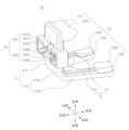
도 1은 종래의 경골 절삭 가이드(91)에 관한 것으로, 이는 미국등록특허공보 제6,090,114호(2000.07.18)에 개시되어 있다. 도 1을 참고하여 설명하면, 상기 경골 절삭 가이드(91)는 커팅 블록(911)을 위치 설정하기 위해서 제1가이드로드(912), 서포트암(913), 전측끼움로드(914), 발목클램프(915), 제2가이드로드(916), 탑바(917), 연장로드(918) 등의 수많은 기구가 필요하며, 이러한 수술기구를 사용하여 많은 단계를 거쳐야 비로소 커팅 블록(911)의 정위치 고정이 가능했다. 따라서 상기 종래 기술에 의할 경우, 커팅 블록(911)을 위치 설정시키기 위한 시간이 많이 소요되기 때문에, 수술 시간이 길어지게 되며, 이는 결국 환자의 수술 위험도를 높이는 원인으로 작용할 수 있게 된다.FIG. 1 relates to a conventional tibial cutting guide (91), which is disclosed in U.S. Patent Publication No. 6,090,114 (July 18, 2000). Referring to FIG. 1, the tibial cutting guide (91) requires numerous instruments such as a first guide rod (912), a support arm (913), a front insertion rod (914), an ankle clamp (915), a second guide rod (916), a top bar (917), and an extension rod (918) to position a cutting block (911), and it was only after going through many steps using these surgical instruments that the cutting block (911) could be fixed in the correct position. Therefore, in the case of the conventional technology, since it takes a lot of time to position the cutting block (911), the surgical time becomes longer, which can ultimately act as a cause of increasing the surgical risk for the patient.
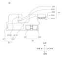
도 2는 종래의 환자 맞춤형 수술가이드(93)에 관한 것으로, 이는 미국공개특허공보 제2010-0217338호(2010.08.26)에 개시되어 있다. 전술한 도 1과 같은 기술의 문제점을 해결하고자, 도 2의 종래 기술에서는 커팅 블록(93) 중 환자의 골과 접하는 부분(931)을 환자의 해부학적 형상에 상보적인 형상을 가지도록 구성함으로써, 커팅 블록(93)의 골접촉부(931)를 특정 지점에 일치시키는 행위만으로도 손 쉽게 커팅 블록(93)을 위치 설정할 수 있도록 하였다.Fig. 2 relates to a conventional patient-tailored surgical guide (93), which is disclosed in U.S. Patent Publication No. 2010-0217338 (August 26, 2010). In order to solve the problems of the technology such as that of Fig. 1 described above, in the conventional technology of Fig. 2, the portion (931) of the cutting block (93) that comes into contact with the patient's bone is configured to have a shape complementary to the patient's anatomical shape, so that the cutting block (93) can be easily positioned simply by aligning the bone contact portion (931) of the cutting block (93) with a specific point.
하지만, 이러한 커팅 블록(93)의 경우, 골접촉부(931)의 면적이 비교적 넓은 범위에 걸쳐 형성되다 보니, 넓은 골접촉부(931)가 환자의 골과 일대일로 완벽히 일치되어야 정확한 위치 설정이 가능해지며, 어느 한 부분에 미세한 이물질이라도 끼게 되면 이격 공간이 발생하게 되면서 상기 골접촉부(931)와 환자의 골 간의 완전한 밀착 접촉이 어려워져 이는 곧 정확한 위치 설정을 어렵게 만드는 요인이 될 수 있다.However, in the case of these cutting blocks (93), since the area of the bone contact portion (931) is formed over a relatively wide range, the wide bone contact portion (931) must perfectly match the patient's bone one-to-one to enable accurate positioning, and if even a small foreign substance gets caught in any part, a gap space is created, making it difficult to achieve complete close contact between the bone contact portion (931) and the patient's bone, which can soon become a factor that makes accurate positioning difficult.
이에 관련 업계에서는 환자 맞춤형 표면을 가지는 부분을 최소화하되, 최소한의 환자 맞춤형 표면을 통해 수술 중 수술기구의 정확한 위치를 설정할 수 있도록 하는 새로운 기술의 도입을 요구하고 있는 실정이다.Accordingly, the relevant industry is demanding the introduction of a new technology that minimizes the portion with patient-specific surfaces while enabling precise positioning of surgical instruments during surgery through a minimal patient-specific surface.
본 발명은 상기와 같은 문제점을 해결하고자 안출된 것으로,The present invention has been devised to solve the above problems.
본 발명의 목적은, 수술기구를 사전에 계획된 대강의 지점으로 가져간 뒤 수술기구를 움직여 가면서 골접촉부가 환자의 골에 밀착하게 되는 위치를 찾도록 함으로써, 환자의 체액, 피, 이물질 등이 낭자하는 수술환경에서 수술의가 용이하고 정확하게 수술기구의 위치를 설정할 수 있도록 하는 환자 맞춤형 수술기구를 제공하는 것이다.The purpose of the present invention is to provide a patient-tailored surgical instrument that allows a surgeon to easily and accurately set the position of a surgical instrument in a surgical environment where a patient's body fluids, blood, foreign substances, etc. are present by bringing the surgical instrument to a roughly planned point in advance and then moving the surgical instrument to find a position where the bone contact part comes into close contact with the patient's bone.
본 발명의 다른 목적은, 포인트 접촉을 하는 환자 맞춤형 대퇴골 수술기구를 구성하여, 핵심 지점만 대퇴골에 정확하게 대응시키면 대퇴골 수술기구가 사전에 계획된 위치에 정확하게 위치 설정될 수 있도록 하는 환자 맞춤형 대퇴골 수술기구를 제공하는 것이다.Another object of the present invention is to provide a patient-specific femoral surgical instrument that configures a point contact patient-specific femoral surgical instrument so that the femoral surgical instrument can be accurately positioned at a pre-planned position by precisely corresponding only key points to the femur.
본 발명의 또 다른 목적은, 대퇴골 샤프트부의 일면에서 타면을 관통하도록 형성된 대퇴골 윈도우부를 구성하여, 수술의가 수술 과정에서 상기 대퇴골 윈도우부를 통해 대퇴골 측을 용이하게 확인할 수 있도록 하면서, 수술기구의 무게가 감소되도록 하는 환자 맞춤형 대퇴골 수술기구를 제공하는 것이다.Another object of the present invention is to provide a patient-tailored femoral surgical instrument that has a femoral window formed to penetrate one surface of a femoral shaft portion and the other surface, thereby allowing a surgeon to easily check the femur side through the femoral window portion during the surgical procedure, while reducing the weight of the surgical instrument.
본 발명의 또 다른 목적은, 상기 대퇴골 윈도우부를 중심으로 비원형의 대퇴골 지그 수용부를 양측에 구성하여, 상기 대퇴골 지그 수용부 내에 가이드 핀을 안내하는 대퇴골 지그가 수용되어 움직이지 않도록 하여 사전에 계획된 위치 및 방향을 따라 가이드 핀을 대퇴골에 정확하게 삽입할 수 있도록 하는 환자 맞춤형 대퇴골 수술기구를 제공하는 것이다.Another object of the present invention is to provide a patient-tailored femoral surgical instrument, which comprises non-circular femoral jig receiving portions formed on both sides centered on the femoral window portion, such that a femoral jig guiding a guide pin is received in the femoral jig receiving portion and prevented from moving, thereby enabling the guide pin to be accurately inserted into the femur along a pre-planned position and direction.
본 발명의 또 다른 목적은, 대퇴골 지그 수용부에 전측에서 후측 방향으로 함입된 대퇴골 함입부를 구성하여, 상기 대퇴골 지그 수용부에 수용된 대퇴골 지그를 용이하게 제거할 수 있도록 하는 환자 맞춤형 대퇴골 수술기구를 제공하는 것이다.Another object of the present invention is to provide a patient-tailored femoral surgical instrument that forms a femoral recessed portion that is recessed from the front to the back in a femoral jig receiving portion, thereby allowing a femoral jig received in the femoral jig receiving portion to be easily removed.
본 발명의 또 다른 목적은, 대퇴골 지그 수용부에 대퇴골 지그 수용공간의 엣지 부분에 대퇴골 지그 수용공간과 연통되는 구멍인 대퇴골 엣지홀을 구성하여, 대퇴골 지그 삽입이 용이해지도록 하는 환자 맞춤형 대퇴골 수술기구를 제공하는 것이다.Another object of the present invention is to provide a patient-tailored femoral surgical instrument in which a femoral edge hole, which is a hole communicating with a femoral jig receiving space at an edge portion of a femoral jig receiving portion, is formed to facilitate insertion of a femoral jig.
본 발명의 또 다른 목적은, 대퇴골 보강부를 구성해 수술기구의 자중 증가를 최소화하면서 강도를 높이는 환자 맞춤형 대퇴골 수술기구를 제공하는 것이다.Another object of the present invention is to provide a patient-specific femoral surgical instrument that increases strength while minimizing an increase in the dead weight of the surgical instrument by forming a femoral reinforcement part.
본 발명의 또 다른 목적은, 대퇴골 원위부 전측 피질 축에 수직한 원위 커팅 면에 나란한 방향으로 상기 가이드 핀이 안내될 수 있도록 상기 대퇴골 지그를 수용하는 대퇴골 지그 수용부를 구성하여, 골 휨(Bone Bowing)이 발생한 환자에게 임플란트를 삽입하는 과정에서 임플란트와 골이 간섭되는 노칭(Notching)이 발생하지 않도록 하는 환자 맞춤형 대퇴골 수술기구를 제공하는 것이다.Another object of the present invention is to provide a patient-tailored femoral surgical instrument that configures a femoral jig receiving portion that receives the femoral jig so that the guide pin can be guided in a direction parallel to a distal cutting surface perpendicular to the anterior cortical axis of the distal portion of the femur, thereby preventing notching, in which the implant interferes with the bone, during the process of inserting the implant into a patient with bone bowing.
본 발명의 또 다른 목적은, 포인트 접촉을 하는 환자 맞춤형 경골 수술기구를 구성하여, 핵심 지점만 경골에 정확하게 대응시키면 경골 수술기구가 사전에 계획된 위치에 정확하게 위치 설정될 수 있도록 하는 환자 맞춤형 경골 수술기구를 제공하는 것이다.Another object of the present invention is to provide a patient-tailored tibial surgical instrument that configures a point contact patient-tailored tibial surgical instrument so that the tibial surgical instrument can be accurately positioned at a pre-planned position by precisely corresponding only key points to the tibia.
본 발명의 또 다른 목적은, 비원형의 경골 지그 수용부를 구성하여, 상기 경골 지그 수용부 내에 가이드 핀을 안내하는 경골 지그가 수용되어 움직이지 않도록 하여 사전에 계획된 위치 및 방향을 따라 가이드 핀을 경골에 정확하게 삽입할 수 있도록 하는 환자 맞춤형 경골 수술기구를 제공하는 것이다.Another object of the present invention is to provide a patient-tailored tibial surgical instrument having a non-circular tibial jig receiving portion, such that a tibial jig guiding a guide pin is received within the tibial jig receiving portion and prevented from moving, thereby enabling the guide pin to be accurately inserted into the tibia along a pre-planned position and direction.
본 발명의 또 다른 목적은, 경골 지그 수용부에 전측에서 후측 방향으로 함입된 경골 함입부를 구성하여, 상기 경골 지그 수용부에 수용된 경골 지그를 용이하게 제거할 수 있도록 하는 환자 맞춤형 경골 수술기구를 제공하는 것이다.Another object of the present invention is to provide a patient-tailored tibial surgical instrument having a tibial recessed portion recessed from the anterior to the posterior direction in a tibial jig receiving portion, thereby allowing a tibial jig received in the tibial jig receiving portion to be easily removed.
본 발명의 또 다른 목적은, 경골 지그 수용부에 경골 지그 수용공간의 엣지 부분에 경골 지그 수용공간과 연통되는 구멍인 경골 엣지홀을 구성하여, 경골 지그 삽입이 용이해지도록 하는 환자 맞춤형 경골 수술기구를 제공하는 것이다.Another object of the present invention is to provide a patient-tailored tibial surgical instrument in which a tibial edge hole, which is a hole communicating with a tibial jig receiving space at an edge portion of a tibial jig receiving portion, is formed to facilitate insertion of a tibial jig.
본 발명의 또 다른 목적은, 경골 샤프트부의 일면에서 타면을 관통하도록 형성된 경골 윈도우부를 구성하여, 수술의가 수술 과정에서 상기 경골 윈도우부를 통해 경골 측을 용이하게 확인할 수 있도록 하면서, 수술기구의 무게가 감소되도록 하는 환자 맞춤형 경골 수술기구를 제공하는 것이다.Another object of the present invention is to provide a patient-tailored tibial surgical instrument having a tibial window formed to penetrate one surface of a tibial shaft portion and the other surface, thereby allowing a surgeon to easily check the tibia side through the tibial window portion during the surgical procedure, while reducing the weight of the surgical instrument.
본 발명의 또 다른 목적은, 경골 근위부 후측 피질 축에 수직한 방향으로 가이드 핀이 안내될 수 있도록 경골 지그를 수용하는 경골 지그 수용부를 구성하여, 경골 근위부에 경골 임플란트를 삽입할 때, 경골 임플란트의 스템 부분이 경골 근위부 후측 피질 축에 가까워지는 것을 방지하는 환자 맞춤형 경골 수술기구를 제공하는 것이다.Another object of the present invention is to provide a patient-tailored tibial surgical instrument that configures a tibial jig receiving portion that receives a tibial jig so that a guide pin can be guided in a direction perpendicular to the posterior cortical axis of the proximal tibia, thereby preventing a stem portion of a tibial implant from approaching the posterior cortical axis of the proximal tibia when inserting the tibial implant into the proximal tibia.
본 발명은 앞서 본 목적을 달성하기 위해서 다음과 같은 구성을 가진 실시예에 의해서 구현된다.In order to achieve the above-mentioned purpose, the present invention is implemented by an embodiment having the following configuration.
본 발명의 일 실시예에 따르면, 본 발명은, 몸체를 형성하는 대퇴골 바디부와, 상기 대퇴골 바디부로부터 골 측으로 돌출 형성되어 대퇴골 표면에 접촉하는 대퇴골 접촉부와, 상기 대퇴골 바디부에 결합되어 가이드 핀을 안내하는 대퇴골 지그가 수용되는 대퇴골 지그 공간을 형성하는 대퇴골 지그 수용부를 포함하고, 상기 대퇴골 바디부는, 대퇴골의 원위부 골 샤프트 방향을 따라 형성되는 대퇴골 샤프트부와, 대퇴골의 원위부 관절구 방향을 따라 형성되는 대퇴골 관절부를 포함하며, 상기 대퇴골 관절부는, 대퇴골의 원위부 내측 관절구를 따라 형성되는 대퇴골 내측 관절부와, 대퇴골의 원위부 외측 관절구를 따라 형성되는 대퇴골 외측 관절부를 포함하고, 상기 대퇴골 접촉부는, 상기 대퇴골 샤프트부의 골측면으로부터 대퇴골의 원위부 골 샤프트 측으로 돌출 형성되며 상기 대퇴골의 원위부 골 샤프트 중 제1 지점 표면에 상보적인 형상을 가지는 대퇴골 제1 접촉면이 형성된 대퇴골 제1 접촉부와, 상기 대퇴골 내측 관절부의 골측면으로부터 대퇴골의 원위부 내측 관절구 측으로 돌출 형성되며 상기 대퇴골의 원위부 내측 관절구 중 제2 지점 표면에 상보적인 형상을 가지는 대퇴골 제2 접촉면이 형성된 대퇴골 제2 접촉부와, 상기 대퇴골 외측 관절부의 골측면으로부터 대퇴골의 원위부 외측 관절구 측으로 돌출 형성되며 상기 대퇴골의 원위부 외측 관절구 중 제3 지점 표면에 상보적인 형상을 가지는 대퇴골 제3 접촉면이 형성된 대퇴골 제3 접촉부를 포함하여, 포인트 접촉을 통해 대퇴골 수술기구의 정확한 위치를 설정하는 것을 특징으로 한다.According to one embodiment of the present invention, the present invention includes a femur body forming a body, a femur contact portion protruding from the femur body toward a bone and contacting a femur surface, and a femur jig receiving portion forming a femur jig space in which a femur jig coupled to the femur body portion and guiding a guide pin is received, wherein the femur body portion includes a femur shaft portion formed along a distal bone shaft direction of the femur, and a femur joint portion formed along a distal condyle direction of the femur, wherein the femur joint portion includes a femur medial joint portion formed along a distal medial condyle of the femur, and a femur lateral joint portion formed along a distal lateral condyle of the femur, and wherein the femur contact portion includes a femur first contact surface formed protruding from a bone side surface of the femur shaft portion toward the distal bone shaft of the femur and having a shape complementary to a surface of a first point of the distal bone shaft of the femur. The present invention is characterized by including a first contact portion, a second femoral contact portion formed by protruding from the bony surface of the femoral medial joint portion toward the distal medial condyle of the femur and having a shape complementary to a surface of a second point of the distal medial condyle of the femur, and a third femoral contact portion formed by protruding from the bony surface of the femoral lateral joint portion toward the distal lateral condyle of the femur and having a shape complementary to a surface of a third point of the distal lateral condyle of the femur, thereby setting an accurate position of a femoral surgical instrument through point contact.
본 발명의 다른 실시예에 따르면, 본 발명은, 상기 대퇴골 지그 수용부는, 내측에 형성된 제1 대퇴골 지그 수용부와, 외측에 형성된 제2 대퇴골 지그 수용부를 포함하며, 상기 제1 대퇴골 지그 수용부는, 가이드 핀을 안내하는 대퇴골 지그를 수용하는 비원형의 공간인 제1 대퇴골 지그 수용공간과, 제1 대퇴골 지그 수용부의 벽면을 전측에서 후측 방향으로 함입시킨 제1 대퇴골 함입부와, 상기 대퇴골 지그의 삽입이 용이하도록 비원형의 제1 대퇴골 지그 수용공간의 엣지에 형성되어 상기 제1 대퇴골 지그 수용공간과 연통되는 구멍인 제1 대퇴골 엣지홀을 포함하고, 상기 제2 대퇴골 지그 수용부는, 가이드 핀을 안내하는 대퇴골 지그를 수용하는 비원형의 공간인 제2 대퇴골 지그 수용공간과, 제1 대퇴골 지그 수용부의 벽면을 전측에서 후측 방향으로 함입시킨 제2 대퇴골 함입부와, 상기 대퇴골 지그의 삽입이 용이하도록 비원형의 제2 대퇴골 지그 수용공간의 엣지에 형성되어 상기 제2 대퇴골 지그 수용공간과 연통되는 구멍인 제2 대퇴골 엣지홀을 포함하는 것을 특징으로 한다.According to another embodiment of the present invention, the femur jig receiving portion includes a first femur jig receiving portion formed on the inside and a second femur jig receiving portion formed on the outside, the first femur jig receiving portion includes a first femur jig receiving space which is a non-circular space for receiving a femur jig guiding a guide pin, a first femur recessed portion in which a wall surface of the first femur jig receiving portion is recessed from the front to the rear, and a first femur edge hole which is a hole formed at an edge of the first femur jig receiving space which is non-circular to facilitate insertion of the femur jig and is communicated with the first femur jig receiving space, and the second femur jig receiving portion includes a second femur jig receiving space which is a non-circular space for receiving a femur jig guiding a guide pin, a second femur recessed portion in which a wall surface of the first femur jig receiving portion is recessed from the front to the rear, and the It is characterized by including a second femur edge hole, which is formed at the edge of a non-circular second femur jig receiving space to facilitate insertion of a femur jig and is a hole communicating with the second femur jig receiving space.
본 발명의 또 다른 실시예에 따르면, 본 발명은, 상기 대퇴골 샤프트부는, 대퇴골 샤프트부의 일면에서 타면을 관통하도록 형성된 대퇴골 윈도우부를 포함하며, 상기 제1 대퇴골 지그 수용부는, 상기 대퇴골 윈도우부를 중심으로 내측에 형성되고, 상기 제2 대퇴골 지그 수용부는, 상기 대퇴골 윈도우부를 중심으로 외측에 형성되는 것을 특징으로 한다.According to another embodiment of the present invention, the present invention is characterized in that the femur shaft portion includes a femur window portion formed to penetrate one surface of the femur shaft portion through the other surface, the first femur jig receiving portion is formed on the inner side with the femur window portion as the center, and the second femur jig receiving portion is formed on the outer side with the femur window portion as the center.
본 발명의 또 다른 실시예에 따르면, 본 발명은, 상기 환자 맞춤형 대퇴골 수술기구는, 상기 대퇴골 바디부로부터 골 측으로 돌출 형성되되, 상기 대퇴골 접촉부와 상기 대퇴골 지그 수용부를 연결하도록 형성된 대퇴골 보강부를 포함하고, 상기 대퇴골 보강부는, 상기 대퇴골 제1 접촉부, 상기 제1 대퇴골 지그 수용부 및 상기 대퇴골 제2 접촉부를 차례로 연결하도록 형성된 제1 대퇴골 보강부와, 상기 대퇴골 제1 접촉부, 상기 제2 대퇴골 지그 수용부 및 상기 대퇴골 제3 접촉부를 차례로 연결하도록 형성된 제2 대퇴골 보강부를 포함하는 것을 특징으로 한다.According to another embodiment of the present invention, the patient-tailored femoral surgical instrument includes a femur reinforcing part formed to protrude from the femur body toward the bone and to connect the femur contact part and the femur jig receiving part, and the femur reinforcing part includes a first femur reinforcing part formed to sequentially connect the femur first contact part, the first femur jig receiving part, and the femur second contact part, and a second femur reinforcing part formed to sequentially connect the femur first contact part, the second femur jig receiving part, and the femur third contact part.
본 발명의 또 다른 실시예에 따르면, 본 발명은, 상기 대퇴골 지그 수용부는, 대퇴골 원위부 전측 피질 축에 수직한 방향으로 상기 가이드 핀이 안내될 수 있도록 상기 대퇴골 지그를 수용하는 것을 특징으로 한다.According to another embodiment of the present invention, the present invention is characterized in that the femur jig receiving portion receives the femur jig such that the guide pin can be guided in a direction perpendicular to the anterior cortical axis of the distal femur.
본 발명의 또 다른 실시예에 따르면, 본 발명은, 몸체를 형성하는 경골 바디부와, 상기 경골 바디부로부터 골 측으로 돌출 형성되어 경골 표면에 접촉하는 경골 접촉부와, 상기 경골 바디부에 결합되어 가이드 핀을 안내하는 경골 지그가 수용되는 경골 지그 공간을 형성하는 경골 지그 수용부를 포함하고, 상기 경골 바디부는, 경골의 근위부 골 샤프트 방향을 따라 형성되는 경골 샤프트부와, 경골의 근위부 관절면 방향을 따라 형성되는 경골 관절부를 포함하며, 상기 경골 관절부는, 경골의 근위부 내측 관절면을 따라 형성되는 경골 내측 관절부와, 경골의 근위부 외측 관절면을 따라 형성되는 경골 외측 관절부를 포함하고, 상기 경골 접촉부는, 상기 경골 샤프트부의 골측면으로부터 경골의 근위부 골 샤프트 측으로 돌출 형성되며 상기 경골의 근위부 골 샤프트 중 제1 지점 표면에 상보적인 형상을 가지는 경골 제1 접촉면이 형성된 경골 제1 접촉부와, 상기 경골 내측 관절부의 골측면으로부터 경골의 근위부 내측 관절면 측으로 돌출 형성되며 상기 경골의 근위부 내측 관절면 중 제2 지점 표면에 상보적인 형상을 가지는 경골 제2 접촉면이 형성된 경골 제2 접촉부와, 상기 경골 외측 관절부의 골측면으로부터 경골의 근위부 외측 관절면 측으로 돌출 형성되며 상기 경골의 근위부 외측 관절면 중 제3 지점 표면에 상보적인 형상을 가지는 경골 제3 접촉면이 형성된 경골 제3 접촉부를 포함하여, 포인트 접촉을 통해 경골 수술기구의 정확한 위치를 설정하는 것을 특징으로 한다.According to another embodiment of the present invention, the present invention includes a tibial body forming a body, a tibial contact portion protruding from the tibial body toward a bone and contacting a tibial surface, and a tibial jig receiving portion forming a tibial jig space in which a tibial jig coupled to the tibial body portion and guiding a guide pin is received, wherein the tibial body portion includes a tibial shaft portion formed along a direction of a proximal bone shaft of the tibia, and a tibial joint portion formed along a direction of a proximal joint surface of the tibia, and the tibial joint portion includes a tibial medial joint portion formed along a proximal medial joint surface of the tibia, and a tibial lateral joint portion formed along a proximal outer joint surface of the tibia, and the tibial contact portion includes a tibial first contact portion formed protruding from a bone-side surface of the tibial shaft portion toward the proximal bone shaft of the tibia and having a tibial first contact surface having a shape complementary to a surface of a first point of the proximal bone shaft of the tibia, and a tibial lateral joint portion formed from a bone-side surface of the tibial medial joint portion to a proximal inner surface of the tibia. The present invention is characterized in that it comprises a tibial second contact portion formed by protruding toward the articular surface and having a shape complementary to a second point surface of the proximal medial articular surface of the tibia, and a tibial third contact portion formed by protruding from the bony surface of the tibial lateral articular surface of the tibia and having a shape complementary to a third point surface of the proximal lateral articular surface of the tibia, thereby setting an accurate position of a tibial surgical instrument through point contact.
본 발명의 또 다른 실시예에 따르면, 본 발명은, 상기 경골 지그 수용부는, 내측에 형성된 제1 경골 지그 수용부와, 외측에 형성된 제2 경골 지그 수용부를 포함하며, 상기 제1 경골 지그 수용부는, 가이드 핀을 안내하는 경골 지그를 수용하는 비원형의 공간인 제1 경골 지그 수용공간과, 제1 경골 지그 수용부의 벽면을 전측에서 후측 방향으로 함입시킨 제1 경골 함입부와, 상기 경골 지그의 삽입이 용이하도록 비원형의 제1 경골 지그 수용공간의 엣지에 형성되어 상기 제1 경골 지그 수용공간과 연통되는 구멍인 제1 경골 엣지홀을 포함하고, 상기 제2 경골 지그 수용부는, 가이드 핀을 안내하는 경골 지그를 수용하는 비원형의 공간인 제2 경골 지그 수용공간과, 제2 경골 지그 수용부의 벽면을 전측에서 후측 방향으로 함입시킨 제2 경골 함입부와, 상기 경골 지그의 삽입이 용이하도록 비원형의 제2 경골 지그 수용공간의 엣지에 형성되어 상기 제2 경골 지그 수용공간과 연통되는 구멍인 제2 경골 엣지홀을 포함하는 것을 특징으로 한다.According to another embodiment of the present invention, the present invention comprises a first tibial jig receiving portion formed on the inside and a second tibial jig receiving portion formed on the outside, wherein the first tibial jig receiving portion comprises a first tibial jig receiving space which is a non-circular space for receiving a tibial jig guiding a guide pin, a first tibial recessed portion in which a wall surface of the first tibial jig receiving portion is recessed from the front to the back, and a first tibial edge hole which is a hole formed at an edge of the first tibial jig receiving space which is non-circular to facilitate insertion of the tibial jig and communicates with the first tibial jig receiving space, and the second tibial jig receiving portion comprises a second tibial jig receiving space which is a non-circular space for receiving a tibial jig guiding a guide pin, a second tibial recessed portion in which a wall surface of the second tibial jig receiving portion is recessed from the front to the back, and a second tibial edge hole which is a non-circular hole for facilitate insertion of the tibial jig. It is characterized by including a second tibial edge hole, which is a hole formed at the edge of the jig receiving space and communicates with the second tibial jig receiving space.
본 발명의 또 다른 실시예에 따르면, 본 발명은, 상기 경골 샤프트부는, 경골 샤프트부의 일면에서 타면을 관통하도록 형성된 경골 윈도우부를 포함하며, 상기 제1 경골 지그 수용부는, 상기 경골 윈도우부를 중심으로 내측에 형성되고, 상기 제2 경골 지그 수용부는, 상기 경골 윈도우부를 중심으로 외측에 형성되는 것을 특징으로 한다.According to another embodiment of the present invention, the present invention is characterized in that the tibial shaft portion includes a tibial window portion formed to penetrate one surface of the tibial shaft portion and the other surface, the first tibial jig receiving portion is formed on the inside with the tibial window portion as the center, and the second tibial jig receiving portion is formed on the outside with the tibial window portion as the center.
본 발명의 또 다른 실시예에 따르면, 본 발명은, 상기 경골 지그 수용부는, 경골 근위부 후측 피질 축에 수직한 방향으로 상기 가이드 핀이 안내될 수 있도록 상기 경골 지그를 수용하는 것을 특징으로 한다.According to another embodiment of the present invention, the present invention is characterized in that the tibial jig receiving portion receives the tibial jig such that the guide pin can be guided in a direction perpendicular to the posterior cortical axis of the proximal portion of the tibia.
본 발명은 앞서 본 실시예와 하기에 설명할 구성과 결합, 사용관계에 의해 다음과 같은 효과를 얻을 수 있다.The present invention can obtain the following effects by combining the configuration and use relationship described below with the previously described embodiment.
본 발명은, 수술기구를 사전에 계획된 대강의 지점으로 가져간 뒤 수술기구를 움직여 가면서 골접촉부가 환자의 골에 밀착하게 되는 위치를 찾도록 함으로써, 환자의 체액, 피, 이물질 등이 낭자하는 수술환경에서 수술의가 용이하고 정확하게 수술기구의 위치를 설정할 수 있도록 하는 환자 맞춤형 수술기구를 제공하는 효과를 가진다.The present invention has the effect of providing a patient-tailored surgical instrument that allows a surgeon to easily and accurately set the position of a surgical instrument in a surgical environment where the patient's body fluids, blood, foreign substances, etc. are present, by moving the surgical instrument to a pre-planned rough point and then finding a position where the bone contact part is in close contact with the patient's bone.
본 발명은, 포인트 접촉을 하는 환자 맞춤형 대퇴골 수술기구를 구성하여, 핵심 지점만 대퇴골에 정확하게 대응시키면 대퇴골 수술기구가 사전에 계획된 위치에 정확하게 위치 설정될 수 있도록 하는 환자 맞춤형 대퇴골 수술기구를 제공하는 효과를 도출한다.The present invention provides a patient-tailored femoral surgical instrument that makes point contact, thereby enabling the femoral surgical instrument to be accurately positioned at a pre-planned position by accurately corresponding only key points to the femur.
본 발명은, 대퇴골 샤프트부의 일면에서 타면을 관통하도록 형성된 대퇴골 윈도우부를 구성하여, 수술의가 수술 과정에서 상기 대퇴골 윈도우부를 통해 대퇴골 측을 용이하게 확인할 수 있도록 하면서, 수술기구의 무게가 감소되도록 하는 환자 맞춤형 대퇴골 수술기구를 제공하는 효과가 있다.The present invention provides a patient-tailored femoral surgical instrument that configures a femoral window portion formed to penetrate one surface of a femoral shaft portion to allow a surgeon to easily check the femur side through the femoral window portion during a surgical procedure, while reducing the weight of the surgical instrument.
본 발명은, 상기 대퇴골 윈도우부를 중심으로 비원형의 대퇴골 지그 수용부를 양측에 구성하여, 상기 대퇴골 지그 수용부 내에 가이드 핀을 안내하는 대퇴골 지그가 수용되어 움직이지 않도록 하여 사전에 계획된 위치 및 방향을 따라 가이드 핀을 대퇴골에 정확하게 삽입할 수 있도록 하는 환자 맞춤형 대퇴골 수술기구를 제공하는 효과를 가진다.The present invention has the effect of providing a patient-tailored femoral surgical instrument in which a non-circular femoral jig receiving portion is formed on both sides with the femoral window portion as the center, so that a femoral jig that guides a guide pin is received in the femoral jig receiving portion and prevents it from moving, thereby enabling the guide pin to be accurately inserted into the femur along a pre-planned position and direction.
본 발명은, 대퇴골 지그 수용부에 전측에서 후측 방향으로 함입된 대퇴골 함입부를 구성하여, 상기 대퇴골 지그 수용부에 수용된 대퇴골 지그를 용이하게 제거할 수 있도록 하는 환자 맞춤형 대퇴골 수술기구를 제공하는 효과를 도출한다.The present invention provides a patient-tailored femoral surgical instrument that forms a femoral recessed portion that is recessed from the front to the back in a femoral jig receiving portion, thereby allowing a femoral jig received in the femoral jig receiving portion to be easily removed.
본 발명은, 대퇴골 지그 수용부에 대퇴골 지그 수용공간의 엣지 부분에 대퇴골 지그 수용공간과 연통되는 구멍인 대퇴골 엣지홀을 구성하여, 대퇴골 지그 삽입이 용이해지도록 하는 환자 맞춤형 대퇴골 수술기구를 제공하는 효과가 있다.The present invention has the effect of providing a patient-tailored femoral surgical instrument in which a femoral edge hole, which is a hole communicating with a femoral jig receiving space at an edge portion of a femoral jig receiving portion of a femoral jig, is formed to facilitate insertion of a femoral jig.
본 발명은, 대퇴골 보강부를 구성해 수술기구의 자중 증가를 최소화하면서 강도를 높이는 환자 맞춤형 대퇴골 수술기구를 제공하는 효과를 가진다.The present invention has the effect of providing a patient-tailored femoral surgical instrument that increases strength while minimizing an increase in the dead weight of the surgical instrument by forming a femoral reinforcement part.
본 발명은, 대퇴골 원위부 전측 피질 축에 수직한 원위 커팅 면에 나란한 방향으로 상기 가이드 핀이 안내될 수 있도록 상기 대퇴골 지그를 수용하는 대퇴골 지그 수용부를 구성하여, 골 휨(Bone Bowing)이 발생한 환자에게 임플란트를 삽입하는 과정에서 임플란트와 골이 간섭되는 노칭(Notching)이 발생하지 않도록 하는 환자 맞춤형 대퇴골 수술기구를 제공하는 효과를 도출한다.The present invention provides a patient-tailored femoral surgical instrument that prevents notching, in which an implant interferes with a bone, during the process of inserting an implant into a patient with bone bowing, by configuring a femoral jig receiving portion that receives the femoral jig so that the guide pin can be guided in a direction parallel to a distal cutting surface perpendicular to the anterior cortical axis of the distal portion of the femur.
본 발명은, 포인트 접촉을 하는 환자 맞춤형 경골 수술기구를 구성하여, 핵심 지점만 경골에 정확하게 대응시키면 경골 수술기구가 사전에 계획된 위치에 정확하게 위치 설정될 수 있도록 하는 환자 맞춤형 경골 수술기구를 제공하는 효과가 있다.The present invention has the effect of providing a patient-tailored tibial surgical instrument that configures a patient-tailored tibial surgical instrument that makes point contact, so that the tibial surgical instrument can be accurately positioned at a pre-planned position by accurately corresponding only to key points on the tibia.
본 발명은, 비원형의 경골 지그 수용부를 구성하여, 상기 경골 지그 수용부 내에 가이드 핀을 안내하는 경골 지그가 수용되어 움직이지 않도록 하여 사전에 계획된 위치 및 방향을 따라 가이드 핀을 경골에 정확하게 삽입할 수 있도록 하는 환자 맞춤형 경골 수술기구를 제공하는 효과를 가진다.The present invention has the effect of providing a patient-tailored tibial surgical instrument that configures a non-circular tibial jig receiving portion, so that a tibial jig that guides a guide pin is received within the tibial jig receiving portion and does not move, thereby enabling the guide pin to be accurately inserted into the tibia along a pre-planned position and direction.
본 발명은, 경골 지그 수용부에 전측에서 후측 방향으로 함입된 경골 함입부를 구성하여, 상기 경골 지그 수용부에 수용된 경골 지그를 용이하게 제거할 수 있도록 하는 환자 맞춤형 경골 수술기구를 제공하는 효과를 도출한다.The present invention provides a patient-tailored tibial surgical instrument that forms a tibial recessed portion that is recessed from the front to the back in a tibial jig receiving portion, thereby allowing a tibial jig received in the tibial jig receiving portion to be easily removed.
본 발명은, 경골 지그 수용부에 경골 지그 수용공간의 엣지 부분에 경골 지그 수용공간과 연통되는 구멍인 경골 엣지홀을 구성하여, 경골 지그 삽입이 용이해지도록 하는 환자 맞춤형 경골 수술기구를 제공하는 효과가 있다.The present invention has the effect of providing a patient-tailored tibial surgical instrument in which a tibial edge hole, which is a hole communicating with a tibial jig receiving space at an edge portion of a tibial jig receiving portion, is formed to facilitate insertion of a tibial jig.
본 발명은, 경골 샤프트부의 일면에서 타면을 관통하도록 형성된 경골 윈도우부를 구성하여, 수술의가 수술 과정에서 상기 경골 윈도우부를 통해 경골 측을 용이하게 확인할 수 있도록 하면서, 수술기구의 무게가 감소되도록 하는 환자 맞춤형 경골 수술기구를 제공하는 효과를 가진다.The present invention has the effect of providing a patient-tailored tibial surgical instrument that configures a tibial window portion formed to penetrate one surface of a tibial shaft portion to enable a surgeon to easily check the tibia side through the tibial window portion during the surgical procedure, while reducing the weight of the surgical instrument.
본 발명은, 경골 근위부 후측 피질 축에 수직한 방향으로 가이드 핀이 안내될 수 있도록 경골 지그를 수용하는 경골 지그 수용부를 구성하여, 경골 근위부에 경골 임플란트를 삽입할 때, 경골 임플란트의 스템 부분이 경골 근위부 후측 피질 축에 가까워지는 것을 방지하는 환자 맞춤형 경골 수술기구를 제공하는 효과를 도출한다.The present invention provides a patient-tailored tibial surgical instrument that prevents the stem portion of a tibial implant from approaching the posterior cortical axis of the proximal tibia when inserting a tibial implant into the proximal tibia by configuring a tibial jig receiving portion that receives a tibial jig so that a guide pin can be guided in a direction perpendicular to the posterior cortical axis of the proximal tibia.
도 1은 종래의 경골 절삭 가이드에 관한 도면.
도 2는 종래의 환자 맞춤형 수술가이드에 관한 도면.
도 3은 본 발명의 일 실시예에 따른 환자 맞춤형 대퇴골 수술기구를 도시한 도면.
도 4는 도 3의 환자 맞춤형 대퇴골 수술기구를 다른 시점에서 도시한 도면.
도 5는 도 3을 환자 맞춤형 대퇴골 수술기구를 또 다른 시점에서 도시한 도면.
도 6은 기계 축을 기준으로 하는 시상 정렬시 대퇴골 임플란트를 삽입할 때 노칭이 발생하는 것을 도시한 도면.
도 7은 대퇴골 원위부 전측 피질 축을 기준으로 하는 시상 정렬시 대퇴골 임플란트를 삽입할 때 노칭이 발생하지 않는 것을 도시한 도면.
도 8은 본 발명의 다른 실시예에 따른 환자 맞춤형 경골 수술기구를 도시한 도면.
도 9는 도 8의 환자 맞춤형 경골 수술기구를 다른 시점에서 도시한 도면.
도 10은 도 8의 환자 맞춤형 경골 수술기구를 또 다른 시점에서 도시한 도면.
도 11은 기계 축과 경골 근위부 후측 피질 축을 비교 도시한 도면.
도 12는 기계 축을 기준으로 하는 시상 정렬시 경골 임플란트를 삽입할 때 스템부분이 경골 근위부 후측 피질과 가까워지는 것을 도시한 도면.
도 13은 경골 근위부 후측 피질 축을 기준으로 하는 시상 정렬시 경골 임플란트를 삽입할 때 스템부분이 경골 근위부 후측 피질에 나란해지는 것을 도시한 도면.
도 14는 본 발명의 또 다른 실시예에 따른 환자 맞춤형 경골 수술기구를 도시한 도면.
도 15는 도 14의 환자 맞춤형 경골 수술기구를 다른 시점에서 도시한 도면.
도 16은 도 14의 환자 맞춤형 경골 수술기구를 또 다른 시점에서 도시한 도면.
도 17은 본 발명인 환자 맞춤형 수술기구의 사용 상태도.Figure 1 is a drawing of a conventional tibial cutting guide.
Figure 2 is a drawing of a conventional patient-specific surgical guide.
FIG. 3 is a drawing illustrating a patient-specific femoral surgical instrument according to one embodiment of the present invention.
Figure 4 is a drawing showing the patient-specific femoral surgical instrument of Figure 3 from another viewpoint.
Figure 5 is a drawing showing the patient-specific femoral surgical instrument of Figure 3 from another viewpoint.
Figure 6 is a drawing illustrating the occurrence of notching when inserting a femoral implant with sagittal alignment relative to the machine axis.
Figure 7 is a drawing illustrating that no notching occurs when inserting a femoral implant in sagittal alignment relative to the anterior cortical axis of the distal femur.
FIG. 8 is a drawing illustrating a patient-specific tibial surgical instrument according to another embodiment of the present invention.
Figure 9 is a drawing showing the patient-specific tibial surgical instrument of Figure 8 from another viewpoint.
FIG. 10 is a drawing showing the patient-specific tibial surgical instrument of FIG. 8 from another viewpoint.
Figure 11 is a drawing comparing the machine axis and the posterior cortical axis of the proximal tibia.
Figure 12 is a drawing showing the stem portion coming closer to the posterior cortex of the proximal tibia when inserting a tibial implant in sagittal alignment based on the machine axis.
Figure 13 is a drawing illustrating the stem portion being aligned with the posterior cortex of the proximal tibia when inserting a tibial implant in sagittal alignment based on the posterior cortical axis of the proximal tibia.
FIG. 14 is a drawing illustrating a patient-specific tibial surgical instrument according to another embodiment of the present invention.
Figure 15 is a drawing showing the patient-specific tibial surgical instrument of Figure 14 from another viewpoint.
Figure 16 is a drawing showing the patient-specific tibial surgical instrument of Figure 14 from another viewpoint.
Figure 17 is a diagram showing the state of use of the patient-specific surgical instrument of the present invention.
이하에서는 본 발명에 따른 포인트 접촉을 통해 사전에 계획된 위치에 정확히 놓이는 환자 맞춤형 수술기구의 바람직한 실시 예들을 첨부된 도면을 참조하여 상세히 설명한다. 하기에서 본 발명을 설명함에 있어 공지의 기능 또는 구성에 대한 구체적인 설명이 본 발명의 요지를 불필요하게 흐릴 수 있다고 판단되는 경우에는 그 상세한 설명을 생략하도록 한다. 특별한 정의가 없는 한 본 명세서의 모든 용어는 본 발명이 속하는 기술분야의 통상의 지식을 가진 기술자가 이해하는 당해 용어의 일반적 의미와 동일하고 만약 본 명세서에서 사용된 용어의 의미와 충돌하는 경우에는 본 명세서에서 사용된 정의에 따른다.Hereinafter, preferred embodiments of a patient-specific surgical instrument that is accurately placed at a pre-planned position through point contact according to the present invention will be described in detail with reference to the attached drawings. In the following description of the present invention, if it is determined that a detailed description of a known function or configuration may unnecessarily obscure the gist of the present invention, the detailed description thereof will be omitted. Unless otherwise defined, all terms in this specification have the same general meaning as those terms understood by a person skilled in the art to which the present invention belongs, and if there is a conflict with the meaning of a term used in this specification, the definitions used in this specification shall apply.
상기 환자 맞춤형 수술기구(1)는, 수술기구를 사전에 계획된 대강의 지점으로 가져간 뒤 수술기구를 움직여 가면서 골접촉부가 환자의 골에 밀착하게 되는 위치를 찾도록 함으로써, 환자의 체액, 피, 이물질 등이 낭자하는 수술환경에서 수술의가 용이하고 정확하게 수술기구의 위치를 설정할 수 있도록 한다. 이러한 상기 환자 맞춤형 수술기구(1)는, 환자 맞춤형 대퇴골 수술기구(10)와, 환자 맞춤형 경골 수술기구(30)를 포함한다.The above-described patient-tailored surgical instrument (1) allows the surgeon to easily and accurately set the position of the surgical instrument in a surgical environment where the patient's body fluids, blood, foreign substances, etc. are present by moving the surgical instrument to a roughly planned point in advance and finding a position where the bone contact part is in close contact with the patient's bone. The above-described patient-tailored surgical instrument (1) includes a patient-tailored femur surgical instrument (10) and a patient-tailored tibial surgical instrument (30).
상기 환자 맞춤형 대퇴골 수술기구(10)는, 포인트 접촉을 통해 대퇴골 수술기구의 정확한 위치를 설정하는 것으로, 핵심 지점만 대퇴골에 정확하게 대응시키면 대퇴골 수술기구가 사전에 계획된 위치에 정확하게 위치 설정될 수 있다. 도 3은 본 발명의 일 실시예에 따른 환자 맞춤형 대퇴골 수술기구(1)를 도시한 도면이며, 도 3을 참조하면, 이러한 상기 환자 맞춤형 대퇴골 수술기구(10)는, 대퇴골 바디부(11), 대퇴골 접촉부(13), 대퇴골 지그 수용부(15), 대퇴골 보강부(17)를 포함한다.The above-described patient-tailored femoral surgical instrument (10) sets the exact position of the femoral surgical instrument through point contact, so that if only key points are accurately corresponded to the femur, the femoral surgical instrument can be accurately positioned at a pre-planned position. FIG. 3 is a drawing illustrating a patient-tailored femoral surgical instrument (1) according to one embodiment of the present invention, and referring to FIG. 3, the above-described patient-tailored femoral surgical instrument (10) includes a femoral body portion (11), a femoral contact portion (13), a femoral jig receiving portion (15), and a femoral reinforcement portion (17).
상기 대퇴골 바디부(11)는, 상기 환자 맞춤형 대퇴골 수술기구(10)의 몸체를 형성하는 구성으로, 도 3을 참조하면, 상기 대퇴골 바디부(11)는 대퇴골의 원위부를 감쌀 수 있도록, 전체적으로 'L'자 형상으로 구성될 수 있다. 이러한 상기 대퇴골 바디부(11)는, 대퇴골 샤프트부(111), 대퇴골 관절부(113)를 포함한다.The femoral body (11) above is configured to form the body of the patient-specific femoral surgical instrument (10). Referring to FIG. 3, the femoral body (11) may be configured in an overall 'L' shape so as to be able to surround the distal portion of the femur. The femoral body (11) includes a femoral shaft (111) and a femoral joint (113).
상기 대퇴골 샤프트부(111)는, 대퇴골의 원위부 골 샤프트 방향을 따라 형성되는 구성으로, 도 3에 도시된 바와 같이 판상형으로 구성될 수 있으며, 후술할 대퇴골 관절부(113)와 대략 수직을 이루도록 구성될 수 있다. 이러한 상기 대퇴골 샤프트부(111)는, 대퇴골 윈도우부(1111)를 포함한다.The above femoral shaft portion (111) is configured to be formed along the direction of the distal femoral shaft, and may be configured in a plate shape as illustrated in FIG. 3, and may be configured to be approximately perpendicular to the femoral joint portion (113) described later. The femoral shaft portion (111) includes a femoral window portion (1111).
상기 대퇴골 윈도우부(1111)는, 대퇴골 샤프트부(111)의 일면에서 타면을 관통하도록 형성된 구멍을 말한다. 본 발명은 상기 대퇴골 윈도우부(1111)를 구성하여, 수술의가 수술 과정에서 상기 대퇴골 윈도우부(1111)를 통해 대퇴골 측을 용이하게 확인할 수 있도록 하면서, 불필요한 수술기구의 무게 증가를 방지한다. 도 4를 참조하면, 이러한 대퇴골 윈도우부(1111)의 형상이 대략 원형으로 도시되었으나, 반드시 이러한 형상으로만 제한되는 것은 아니고 이와 다른 다양한 형상으로 구성될 수 있다.The femur window portion (1111) above refers to a hole formed to penetrate one surface of the femur shaft portion (111) through the other surface. The present invention configures the femur window portion (1111) so that the surgeon can easily check the femur side through the femur window portion (1111) during the surgical procedure, while preventing unnecessary weight increase of the surgical instrument. Referring to Fig. 4, the shape of the femur window portion (1111) is depicted as being approximately circular, but is not necessarily limited to this shape and may be configured in various other shapes.
상기 대퇴골 관절부(113)는, 대퇴골의 원위부 관절구 방향을 따라 형성되는 구성으로, 바람직하게는 상기 대퇴골 샤프트부(111)와 대략 수직을 이루도록 구성될 수 있다. 도 5는 도 3을 환자 맞춤형 대퇴골 수술기구(1)를 또 다른 시점에서 도시한 도면으로, 도 5를 참조하면, 이러한 상기 대퇴골 관절부(113)는, 대퇴골 내측 관절부(1131), 대퇴골 외측 관절부(1133)를 포함한다.The femoral joint part (113) is configured to be formed along the direction of the distal joint of the femur, and preferably can be configured to be approximately perpendicular to the femoral shaft part (111). FIG. 5 is a drawing showing the patient-tailored femoral surgical instrument (1) of FIG. 3 from another viewpoint. Referring to FIG. 5, the femoral joint part (113) includes a femoral medial joint part (1131) and a femoral outer joint part (1133).
상기 대퇴골 내측 관절부(1131)는, 대퇴골의 원위부 내측 관절구를 따라 형성되는 구성으로, 도 5에 도시된 바와 같이, 판상형의 형태를 가지되, 폭에 비해 길이가 길게 형성될 수 있다.The above femoral medial joint portion (1131) is formed along the distal medial joint cavity of the femur, and as shown in FIG. 5, has a plate-like shape, but can be formed with a length longer than the width.
상기 대퇴골 외측 관절부(1133)는, 대퇴골의 원위부 외측 관절구를 따라 형성되는 구성으로, 상기 대퇴골 외측 관절부(1133)도 상기 대퇴골 내측 관절부(1131)와 유사하게 판상형의 형태를 가지면서 폭에 비해 긴 길이를 가지도록 형성될 수 있다.The above femoral lateral joint part (1133) is configured to be formed along the distal outer joint cavity of the femur, and the femoral lateral joint part (1133) may also be formed to have a plate-like shape similar to the femoral medial joint part (1131) and to have a longer length than its width.
상기 대퇴골 접촉부(13)는, 상기 대퇴골 바디부(11)로부터 골 측으로 돌출 형성되어 대퇴골 표면에 직접 접촉하는 구성을 말한다. 즉, 상기 대퇴골 접촉부(13)는 환자의 대퇴골과 포인트 접촉을 하는 부분으로, 이러한 포인트 접촉을 위해 상기 대퇴골 접촉부(13)의 골 접촉면은 대응되는 환자의 골 표면 형상과 상보적인 형상을 가지도록 구성될 수 있다. 도 5를 참조하면, 이러한 상기 대퇴골 접촉부(13)는, 대퇴골 제1 접촉부(131), 대퇴골 제2 접촉부(133), 대퇴골 제3 접촉부(135)를 포함한다.The femoral contact portion (13) above refers to a configuration that is formed by protruding from the femoral body portion (11) toward the bone and directly contacting the femoral surface. In other words, the femoral contact portion (13) is a portion that makes point contact with the patient's femur, and for this point contact, the bone contact surface of the femoral contact portion (13) can be configured to have a shape complementary to the corresponding bone surface shape of the patient. Referring to FIG. 5, the femoral contact portion (13) includes a first femoral contact portion (131), a second femoral contact portion (133), and a third femoral contact portion (135).
상기 대퇴골 제1 접촉부(131)는, 상기 대퇴골 샤프트부(111)의 골측면으로부터 대퇴골의 원위부 골 샤프트 측으로 돌출 형성되며 상기 대퇴골의 원위부 골 샤프트 중 제1 지점 표면에 상보적인 형상을 가지는 대퇴골 제1 접촉면(1311)이 형성되는 구성을 말한다. 상기 대퇴골 제1 접촉부(131)는 도 5에 도시된 바와 같이, 상기 대퇴골 샤프트부(111)로부터 수직한 방향으로 돌출 형성될 수 있다. 바람직하게는 상기 제1 지점은 대퇴골의 활차 부위(Trochlear Region) 이외의 지점에 위치할 수 있으며, 보다 바람직하게는 대퇴골의 활차 부위 상측의 골 샤프트에 형성될 수 있다. 따라서, 상기 대퇴골 제1 접촉부(131)는 대퇴골의 활차 부위를 넘어선 골 샤프트 부분에 접촉할 수 있다.The above femoral first contact portion (131) refers to a configuration in which a femoral first contact surface (1311) is formed to protrude from the lateral surface of the femoral shaft portion (111) toward the distal femoral shaft side of the femoral shaft and has a complementary shape to a first point surface of the distal femoral bone shaft. The femoral first contact portion (131) may be formed to protrude in a vertical direction from the femoral shaft portion (111), as illustrated in FIG. 5. Preferably, the first point may be located at a point other than the trochlear region of the femur, and more preferably, may be formed in the bone shaft above the trochlear region of the femur. Therefore, the femoral first contact portion (131) may contact a portion of the bone shaft beyond the trochlear region of the femur.
상기 대퇴골 제2 접촉부(133)는, 상기 대퇴골 내측 관절부(1131)의 골측면으로부터 대퇴골의 원위부 내측 관절구 측으로 돌출 형성되며 상기 대퇴골의 원위부 내측 관절구 중 제2 지점 표면에 상보적인 형상을 가지는 대퇴골 제2 접촉면(1331)이 형성되는 구성을 말한다. 상기 대퇴골 제2 접촉부(133)는 도 5에 도시된 바와 같이, 상기 대퇴골 내측 관절부(1131)로부터 수직한 방향으로 돌출 형성되어 환자의 대퇴골 내측 관절구와 접촉하게 된다.The above femoral second contact portion (133) refers to a configuration in which a femoral second contact surface (1331) is formed by protruding from the bone surface of the femoral medial joint portion (1131) toward the distal medial joint cavity of the femur and having a complementary shape to the surface of the second point of the distal medial joint cavity of the femur. As illustrated in FIG. 5, the femoral second contact portion (133) is formed by protruding in a vertical direction from the femoral medial joint portion (1131) and comes into contact with the patient's femoral medial joint cavity.
상기 대퇴골 제3 접촉부(135)는, 상기 대퇴골 외측 관절부(1133)의 골측면으로부터 대퇴골의 원위부 외측 관절구 측으로 돌출 형성되며 상기 대퇴골의 원위부 외측 관절구 중 제3 지점 표면에 상보적인 형상을 가지는 대퇴골 제3 접촉면(13511)이 형성되는 구성을 말한다. 상기 대퇴골 제3 접촉부(135)는 도 5에 도시된 바와 같이, 상기 대퇴골 외측 관절부(1133)로부터 수직한 방향으로 돌출 형성되어 환자의 대퇴골 외측 관절구에 접촉하게 된다.The above third femoral contact portion (135) refers to a configuration in which a third femoral contact surface (13511) is formed by protruding from the bone surface of the femoral lateral joint portion (1133) toward the distal lateral joint cavity of the femur and having a complementary shape to the surface of the third point of the distal lateral joint cavity of the femur. As illustrated in FIG. 5, the third femoral contact portion (135) is formed by protruding in a vertical direction from the femoral lateral joint portion (1133) and comes into contact with the patient's femoral lateral joint cavity.
상기 대퇴골 지그 수용부(15)는, 상기 대퇴골 바디부(11)에 결합되어 가이드 핀을 안내하는 대퇴골 지그가 수용되는 대퇴골 지그 공간을 형성하는 구성을 말한다. 바람직하게는 상기 대퇴골 지그 수용부(15)는 도 4 및 도 5에 도시된 바와 같이 비원형으로 구성될 수 있다. 이러한 형상은 상기 대퇴골 지그 수용부(15) 내에 가이드 핀을 안내하는 대퇴골 지그가 수용되더라도 다른 방향으로 움직이지 않도록 하는바, 사전에 계획된 위치 및 방향을 따라 가이드 핀을 대퇴골에 정확하게 삽입할 수 있도록 한다.The above femur jig receiving portion (15) refers to a configuration that forms a femur jig space in which a femur jig that guides a guide pin is received by being coupled to the femur body portion (11). Preferably, the femur jig receiving portion (15) may be configured in a non-circular shape as shown in FIGS. 4 and 5. This shape prevents the femur jig that guides the guide pin from moving in a different direction even when it is received in the femur jig receiving portion (15), thereby enabling the guide pin to be accurately inserted into the femur along a pre-planned position and direction.
도 6 및 도 7을 참조하면, 상기 대퇴골 지그 수용부(15)는, 대퇴골 원위부 전측 피질 축(Distal Femur Anterior Cortex Axis, DCX)(A)에 수직한 원위 커팅 면(Distal Cutting Plane)(D)에 나란한 방향, 즉, 상기 대퇴골 원위부 전측 피질축에 수직한 방향으로 상기 가이드 핀이 안내될 수 있도록 상기 대퇴골 지그를 수용하도록 구성된다.Referring to FIGS. 6 and 7, the femur jig receiving portion (15) is configured to receive the femur jig so that the guide pin can be guided in a direction parallel to the distal cutting plane (D) perpendicular to the distal femur anterior cortex axis (DCX) (A) of the femur, i.e., in a direction perpendicular to the distal femur anterior cortex axis.
도 6에 도시된 바와 같이, 골 휨(Bone Bowing)이 발생한 환자의 경우에는 시상 면(Sagittal Plane)을 기준으로 대퇴골의 원위부를 바라보았을 때 골이 전측 방향으로 휘어져 있는바, 기존의 방식대로 기계 축(Mechanical Axis)(M)을 기준으로 기계 축(M)에 수직한 원위 커팅 면(D)을 형성할 경우 임플란트(I)를 삽입했을 때 임플란트(I)가 골과 간섭되는 노칭(Notching)이 발생할 수밖에 없다.As shown in Fig. 6, in the case of a patient with bone bowing, the bone is bent in the anterior direction when looking at the distal portion of the femur based on the sagittal plane. Therefore, if a distal cutting plane (D) perpendicular to the mechanical axis (M) is formed based on the mechanical axis (M) in the conventional manner, when the implant (I) is inserted, notching in which the implant (I) interferes with the bone is bound to occur.
이에 본 발명은 도 7에 도시된 바와 같이, 대퇴골 원위부 전측 피질 축(Distal Femur Anterior Cortex Axis, DCX)(A)에 수직한 원위 커팅 면(Distal Cutting Plane)(D)에 나란한 방향으로 상기 가이드 핀이 안내될 수 있도록 상기 대퇴골 지그를 수용하는 대퇴골 지그 수용부(15)를 구성함으로써, 골 휨(Bone Bowing)이 발생한 환자에게 임플란트를 삽입하는 과정에서 임플란트와 골이 간섭되는 노칭(Notching)이 발생하지 않도록 한다.Accordingly, the present invention configures a femur jig receiving portion (15) for receiving the femur jig so that the guide pin can be guided in a direction parallel to the distal cutting plane (D) perpendicular to the distal femur anterior cortex axis (DCX) (A) of the femur, as illustrated in FIG. 7, thereby preventing notching, in which the implant interferes with the bone, during the process of inserting the implant into a patient with bone bowing.
이러한 상기 대퇴골 지그 수용부(15)는, 제1 대퇴골 지그 수용부(151)와, 제2 대퇴골 지그 수용부(153)를 포함한다.The femur jig receiving portion (15) includes a first femur jig receiving portion (151) and a second femur jig receiving portion (153).
상기 제1 대퇴골 지그 수용부(151)는, 비원형으로 형성되고, 상기 대퇴골 윈도우부(1111)를 중심으로 내측에 형성된 대퇴골 지그 수용부를 말한다. 바람직하게는 상기 제1 대퇴골 지그 수용부(151)는 도 5에 도시된 바와 같이, 내부에 공간을 형성하면서 전측면과 후측면이 개방된 사각의 박스 형태로 구성될 수 있다. 이러한 상기 제1 대퇴골 지그 수용부(151)는, 제1 대퇴골 지그 수용공간(1511), 제1 대퇴골 함입부(1513), 제1 대퇴골 엣지홀(1515)을 포함한다.The above first femur jig receiving portion (151) refers to a femur jig receiving portion formed in a non-circular shape and formed on the inside with the femur window portion (1111) as the center. Preferably, the first femur jig receiving portion (151) may be configured in a square box shape with an open front and rear side while forming a space inside, as illustrated in FIG. 5. The first femur jig receiving portion (151) includes a first femur jig receiving space (1511), a first femur embedding portion (1513), and a first femur edge hole (1515).
상기 제1 대퇴골 지그 수용공간(1511)은, 가이드 핀을 안내하는 대퇴골 지그를 수용하는 비원형의 공간을 말한다. 바람직하게는 상기 비원형의 공간은 도 5에 도시된 바와 같이 사각 박스 형상으로 구성될 수 있다. 이러한 비원형의 공간을 통해 대퇴골 지그가 상기 제1 대퇴골 지그 수용공간(1511)에 삽입되더라도 삽입되는 전후측 방향 이외의 방향으로 움직이는 것을 방지할 수 있게 된다.The above first femur jig receiving space (1511) refers to a non-circular space that receives a femur jig that guides a guide pin. Preferably, the non-circular space may be configured in a square box shape as illustrated in FIG. 5. Through this non-circular space, even if the femur jig is inserted into the first femur jig receiving space (1511), it is possible to prevent the femur jig from moving in a direction other than the anteroposterior direction in which it is inserted.
상기 제1 대퇴골 함입부(1513)는, 상기 제1 대퇴골 지그 수용부(151) 중 상기 대퇴골 윈도우부(1111) 측 벽면을 전측에서 후측 방향으로 함입시킨 부분을 가리킨다. 본 발명은 상기 제1 대퇴골 지그 수용부(151) 상에 상기 제1 대퇴골 함입부(1513)를 구성하여, 상기 제1 대퇴골 지그 수용부(151)에 수용된 대퇴골 지그를 용이하게 제거할 수 있도록 한다.The above first femoral concavity (1513) refers to a portion of the first femoral jig receiving portion (151) in which the wall surface of the femoral window portion (1111) is concaved from the front to the back. The present invention forms the first femoral concavity (1513) on the first femoral jig receiving portion (151), so that the femoral jig received in the first femoral jig receiving portion (151) can be easily removed.
상기 제1 대퇴골 엣지홀(1515)은, 상기 대퇴골 지그의 삽입이 용이하도록 비원형의 제1 대퇴골 지그 수용공간(1511)의 엣지에 형성되어 상기 제1 대퇴골 지그 수용공간(1511)과 연통되는 구멍을 말한다. 이러한 상기 제1 대퇴골 엣지홀(1515)에 의해 상기 제1 대퇴골 지그 수용공간(1511)에 대퇴골 지그를 삽입하는 과정에서 혈액, 이물질 등이 끼더라도 원활한 대퇴골 지그의 삽입이 가능해 지게 된다.The above first femur edge hole (1515) is a hole formed at the edge of a non-circular first femur jig receiving space (1511) to facilitate insertion of the femur jig and communicates with the first femur jig receiving space (1511). Even if blood, foreign substances, etc. get caught in the process of inserting the femur jig into the first femur jig receiving space (1511) by the above first femur edge hole (1515), smooth insertion of the femur jig is possible.
상기 제2 대퇴골 지그 수용부(153)는, 비원형으로 형성되고, 상기 대퇴골 윈도우부(1111)를 중심으로 외측에 형성된 대퇴골 지그 수용부를 말한다. 바람직하게는 상기 제2 대퇴골 지그 수용부(153)는 도 5에 도시된 바와 같이, 내부에 공간을 형성하면서 전측면과 후측면이 개방된 사각의 박스 형태로 구성될 수 있으며, 상기 제1 대퇴골 지그 수용부(151)와 대칭되도록 구성될 수 있다. 이러한 상기 제2 대퇴골 지그 수용부(153)는, 제2 대퇴골 지그 수용공간(1531), 제2 대퇴골 함입부(1533), 제2 대퇴골 엣지홀(1535)을 포함한다.The above second femur jig receiving portion (153) refers to a femur jig receiving portion that is formed in a non-circular shape and is formed on the outside with the femur window portion (1111) as the center. Preferably, the second femur jig receiving portion (153) may be configured in a square box shape with an open front and rear side and a space formed inside, as illustrated in FIG. 5, and may be configured to be symmetrical with the first femur jig receiving portion (151). The second femur jig receiving portion (153) includes a second femur jig receiving space (1531), a second femur embedding portion (1533), and a second femur edge hole (1535).
상기 제2 대퇴골 지그 수용공간(1531)은, 가이드 핀을 안내하는 대퇴골 지그를 수용하는 비원형의 공간을 말한다. 바람직하게는 상기 비원형의 공간은 도 5에 도시된 바와 같이 사각 박스 형상으로 구성될 수 있다. 이러한 비원형의 공간을 통해 대퇴골 지그가 상기 제2 대퇴골 지그 수용공간(1531)에 삽입되더라도 삽입되는 전후측 방향 이외의 방향으로 움직이는 것을 방지할 수 있게 된다.The above second femur jig receiving space (1531) refers to a non-circular space that receives a femur jig that guides a guide pin. Preferably, the non-circular space may be configured in a square box shape as illustrated in FIG. 5. Through this non-circular space, even if the femur jig is inserted into the second femur jig receiving space (1531), it is possible to prevent the femur jig from moving in a direction other than the anteroposterior direction in which it is inserted.
상기 제2 대퇴골 함입부(1533)는, 상기 제2 대퇴골 지그 수용부(153) 중 상기 대퇴골 윈도우부(1111) 측 벽면을 전측에서 후측 방향으로 함입시킨 부분을 가리킨다. 본 발명은 상기 제2 대퇴골 지그 수용부(153) 상에 상기 제2 대퇴골 함입부(1533)를 구성하여, 상기 제2 대퇴골 지그 수용부(153)에 수용된 대퇴골 지그를 용이하게 제거할 수 있도록 한다.The above second femoral concavity (1533) refers to a portion of the second femoral jig receiving portion (153) in which the wall surface on the femoral window portion (1111) side is concaved from the front to the back. The present invention forms the second femoral concavity (1533) on the second femoral jig receiving portion (153) so that the femoral jig received in the second femoral jig receiving portion (153) can be easily removed.
상기 제2 대퇴골 엣지홀(1535)은, 상기 대퇴골 지그의 삽입이 용이하도록 비원형의 제2 대퇴골 지그 수용공간(1531)의 엣지에 형성되어 상기 제2 대퇴골 지그 수용공간(1531)과 연통되는 구멍을 말한다. 이러한 상기 제2 대퇴골 엣지홀(1535)에 의해 상기 제2 대퇴골 지그 수용공간(1531)에 대퇴골 지그를 삽입하는 과정에서 혈액, 이물질 등이 끼더라도 원활한 대퇴골 지그의 삽입이 가능해 지게 된다.The above second femur edge hole (1535) is a hole formed at the edge of a non-circular second femur jig receiving space (1531) to facilitate insertion of the femur jig and communicates with the second femur jig receiving space (1531). Even if blood, foreign substances, etc. get caught in the process of inserting the femur jig into the second femur jig receiving space (1531) by the second femur edge hole (1535), smooth insertion of the femur jig is possible.
상기 대퇴골 보강부(17)는, 상기 대퇴골 바디부(11)로부터 골 측으로 돌출 형성되되, 상기 대퇴골 접촉부(13)와 상기 대퇴골 지그 수용부(15)를 연결하도록 형성되는 구성을 말한다. 본 발명은 이러한 대퇴골 보강부(17)를 구성해, 수술기구의 자중 증가를 최소화하면서 수술기구의 강도를 높이도록 한다. 바람직하게는 상기 대퇴골 보강부(17)는 상기 대퇴골 바디부(11)의 골측면으로부터 폭이 높고 길이간 긴 비드의 형상으로 구성될 수 있으며, 상기 대퇴골 바디부(11)의 골측면으로부터 상기 대퇴골 보강부(17)가 돌출된 높이는, 상기 대퇴골 샤프트부(111)의 골측면으로부터 상기 대퇴골 제1 접촉부(131)가 돌출된 높이, 상기 대퇴골 내측 관절부(1131)의 골측면으로부터 상기 대퇴골 제2 접촉부(133)가 돌출된 높이 및 상기 대퇴골 외측 관절부(1133)의 골측면으로부터 상기 대퇴골 제3 접촉부(135)가 돌출된 높이보다 작게 형성될 수 있다. 이러한 상기 대퇴골 보강부(17)는, 제1 대퇴골 보강부(171), 제2 대퇴골 보강부(173)를 포함한다.The above femur reinforcement part (17) refers to a configuration formed to protrude from the femur body part (11) toward the bone, and to connect the femur contact part (13) and the femur jig receiving part (15). The present invention configures such a femur reinforcement part (17) to increase the strength of the surgical instrument while minimizing an increase in the dead weight of the surgical instrument. Preferably, the femur reinforcement part (17) may be configured in the shape of a bead having a wide width and a long length from the bone side of the femur body (11), and the height at which the femur reinforcement part (17) protrudes from the bone side of the femur body (11) may be formed smaller than the height at which the first femur contact part (131) protrudes from the bone side of the femur shaft part (111), the height at which the second femur contact part (133) protrudes from the bone side of the femur inner joint part (1131), and the height at which the third femur contact part (135) protrudes from the bone side of the femur outer joint part (1133). The femur reinforcement part (17) includes a first femur reinforcement part (171) and a second femur reinforcement part (173).
상기 제1 대퇴골 보강부(171)는, 상기 대퇴골 제1 접촉부(131), 상기 제1 대퇴골 지그 수용부(151) 및 상기 대퇴골 제2 접촉부(133)를 차례로 연결하도록 형성되는 구성을 말한다.The above first femur reinforcement part (171) refers to a configuration formed to sequentially connect the first femur contact part (131), the first femur jig receiving part (151), and the second femur contact part (133).
상기 제2 대퇴골 보강부(173)는, 상기 대퇴골 제1 접촉부(131), 상기 제2 대퇴골 지그 수용부(153) 및 상기 대퇴골 제3 접촉부(135)를 차례로 연결하도록 형성되는 구성을 말한다.The above second femur reinforcement part (173) refers to a configuration formed to sequentially connect the first femur contact part (131), the second femur jig receiving part (153), and the third femur contact part (135).
도 8 내지 도 10은 본 발명의 다른 실시예인 환자 맞춤형 경골 수술기구(30)를 도시한 도면으로, 이하에서는 도 8 내지 도 10을 참조해 상기 환자 맞춤형 경골 수술기구(30)에 대해 설명하도록 하겠다.FIGS. 8 to 10 are drawings illustrating a patient-tailored tibial surgical instrument (30) according to another embodiment of the present invention. Hereinafter, the patient-tailored tibial surgical instrument (30) will be described with reference to FIGS. 8 to 10.
상기 환자 맞춤형 경골 수술기구(30)는, 포인트 접촉을 통해 경골 수술기구의 정확한 위치를 설정하는 것으로, 포인트 접촉을 하는 환자 맞춤형 경골 수술기구를 구성하여, 핵심 지점만 경골에 정확하게 대응시키면 경골 수술기구가 사전에 계획된 위치에 정확하게 위치 설정될 수 있도록 한다. 도 8은 본 발명의 다른 실시예에 따른 환자 맞춤형 경골 수술기구(30)를 도시한 도면이며, 도 8을 참조하면, 이러한 상기 환자 맞춤형 경골 수술기구(30)는, 경골 바디부(31), 경골 접촉부(33), 경골 지그 수용부(35)를 포함한다.The above-described patient-tailored tibial surgical instrument (30) sets the exact position of the tibial surgical instrument through point contact, and configures a patient-tailored tibial surgical instrument that makes point contact so that only key points correspond accurately to the tibia, so that the tibial surgical instrument can be accurately positioned at a pre-planned position. FIG. 8 is a drawing illustrating a patient-tailored tibial surgical instrument (30) according to another embodiment of the present invention, and with reference to FIG. 8, the above-described patient-tailored tibial surgical instrument (30) includes a tibial body portion (31), a tibial contact portion (33), and a tibial jig receiving portion (35).
상기 경골 바디부(31)는, 몸체를 형성하는 구성으로, 도 8을 참고하면, 이러한 상기 경골 바디부(31)는 경골의 근위부를 감쌀 수 있도록, 전체적으로 'ㄱ'자 형상으로 구성될 수 있다. 이러한 상기 경골 바디부(31)는, 경골 샤프트부(311), 경골 관절부(313)를 포함한다.The above tibial body part (31) is configured to form a body, and with reference to FIG. 8, the above tibial body part (31) may be configured in an overall 'ㄱ' shape so as to be able to surround the proximal portion of the tibia. The above tibial body part (31) includes a tibial shaft part (311) and a tibial joint part (313).
상기 경골 샤프트부(311)는, 경골의 근위부 골 샤프트 방향을 따라 형성되는 구성으로, 도 8에 도시된 바와 같이 대략 판상형으로 구성될 수 있으며, 후술할 경골 관절부(313)와 대략 수직을 이루도록 구성될 수 있다. 이러한 상기 경골 샤프트부(311)는 경골 윈도우부(3111)를 포함한다.The above tibial shaft portion (311) is configured to be formed along the direction of the proximal bone shaft of the tibia, and may be configured to be approximately plate-shaped as illustrated in FIG. 8, and may be configured to be approximately perpendicular to the tibial joint portion (313) described later. The above tibial shaft portion (311) includes a tibial window portion (3111).
상기 경골 윈도우부(3111)는, 경골 샤프트부(311)의 일면에서 타면을 관통하도록 형성된 구멍을 말한다. 본 발명은 상기 경골 윈도우부(3111)를 구성하여, 수술의가 수술 과정에서 상기 경골 윈도우부(3111)를 통해 경골 측을 용이하게 확인할 수 있도록 하며, 수술기구의 전체 중량을 감소시켜 수술의가 용이하게 수술기구를 파지한 상태로 수술을 진행할 수 있도록 한다. 바람직하게는 도 9에 도시된 바와 같이, 상기 경골 윈도우부(3111)는 후술할 제1 경골 지그 수용부(351)와 제2 경골 지그 수용부(353) 사이에 형성될 수 있다.The above tibial window portion (3111) refers to a hole formed to penetrate one surface of the tibial shaft portion (311) to the other surface. The present invention configures the above tibial window portion (3111) so that the surgeon can easily check the tibia side through the above tibial window portion (3111) during the surgical procedure, and reduces the overall weight of the surgical instrument so that the surgeon can easily hold the surgical instrument and perform the surgical procedure. Preferably, as illustrated in FIG. 9, the above tibial window portion (3111) may be formed between the first tibial jig receiving portion (351) and the second tibial jig receiving portion (353), which will be described later.
상기 경골 관절부(313)는, 경골의 근위부 관절면 방향을 따라 형성되는 구성을 말한다. 도 10을 참조하면, 이러한 상기 경골 관절부(313)는, 경골 내측 관절부(3131), 경골 외측 관절부(3133)를 포함한다.The above tibial joint (313) refers to a configuration formed along the direction of the proximal joint surface of the tibia. Referring to Fig. 10, the above tibial joint (313) includes a tibial medial joint (3131) and a tibial outer joint (3133).
상기 경골 내측 관절부(3131)는, 경골의 근위부 내측 관절면을 따라 형성되는 구성으로, 바람직하게는 상기 경골 샤프트부(311)와 대략 수직을 이루도록 구성되며, 폭에 비해 길이가 긴 판상형의 형태로 구성될 수 있다.The above tibial medial joint portion (3131) is configured to be formed along the proximal medial joint surface of the tibia, preferably configured to be approximately perpendicular to the tibial shaft portion (311), and may be configured in a plate-like shape with a length that is longer than its width.
상기 경골 외측 관절부(3133)는, 경골의 근위부 외측 관절면을 따라 형성되는 구성으로, 상기 경골 내측 관절부(3131)와 마찬가지로, 상기 경골 샤프트부(311)와 대략 수직을 이루도록 구성되며, 폭에 비해 길이가 긴 판상형의 형태로 구성됨이 바람직할 수 있다.The above tibial outer joint portion (3133) is configured to be formed along the proximal outer joint surface of the tibia, and, like the above tibial inner joint portion (3131), is configured to be approximately perpendicular to the above tibial shaft portion (311), and may preferably be configured in a plate-like shape with a length that is longer than its width.
상기 경골 접촉부(33)는, 상기 경골 바디부(31)로부터 골 측으로 돌출 형성되어 경골 표면에 접촉하는 구성을 말한다. 즉, 상기 경골 접촉부(33)는 환자의 경골과 포인트 접촉을 하는 부분으로, 이러한 포인트 접촉을 위해 상기 경골 접촉부(33)의 골 접촉면은 대응되는 환자의 골 표면 형상과 상보적인 형상을 가지도록 구성될 수 있다. 도 10을 참조하면, 이러한 상기 경골 접촉부(33)는, 경골 제1 접촉부(331), 경골 제2 접촉부(333), 경골 제3 접촉부(335)를 포함한다.The above tibial contact portion (33) refers to a configuration that is formed by protruding from the tibial body portion (31) toward the bone and contacting the tibial surface. In other words, the above tibial contact portion (33) is a portion that makes point contact with the patient's tibia, and for this point contact, the bone contact surface of the above tibial contact portion (33) can be configured to have a shape complementary to the corresponding bone surface shape of the patient. Referring to FIG. 10, the above tibial contact portion (33) includes a first tibial contact portion (331), a second tibial contact portion (333), and a third tibial contact portion (335).
상기 경골 제1 접촉부(331)는, 상기 경골 샤프트부(311)의 골측면으로부터 경골의 근위부 골 샤프트 측으로 돌출 형성되며 상기 경골의 근위부 골 샤프트 중 제1 지점 표면에 상보적인 형상을 가지는 경골 제1 접촉면(3311)이 형성된 구성을 말한다. 바람직하게는 상기 경골 제1 접촉부(331)는 도 10에 도시된 바와 같이, 상기 경골 샤프트부(311)로부터 대략 수직한 방향으로 돌출 형성될 수 있다.The above tibial first contact portion (331) refers to a configuration in which a tibial first contact surface (3311) is formed by protruding from the bone side of the tibial shaft portion (311) toward the proximal bone shaft of the tibia and having a shape complementary to the surface of the first point of the proximal bone shaft of the tibia. Preferably, the tibial first contact portion (331) may be formed by protruding in a substantially vertical direction from the tibial shaft portion (311), as illustrated in FIG. 10.
상기 경골 제2 접촉부(333)는, 상기 경골 내측 관절부(3131)의 골측면으로부터 경골의 근위부 내측 관절면 측으로 돌출 형성되며 상기 경골의 근위부 내측 관절면 중 제2 지점 표면에 상보적인 형상을 가지는 경골 제2 접촉면(3331)이 형성된 구성을 말한다. 상기 경골 제2 접촉부(333)는 도 10에 도시된 바와 같이, 상기 경골 내측 관절부(3131)로부터 수직한 방향으로 돌출 형성되어 환자의 경골 내측 관절면과 접촉하게 된다.The above-mentioned second tibial contact portion (333) is formed by protruding from the bony surface of the tibial medial joint portion (3131) toward the proximal medial joint surface of the tibia, and is a configuration in which the second tibial contact surface (3331) is formed having a complementary shape to the surface of the second point of the proximal medial joint surface of the tibia. As illustrated in FIG. 10, the above-mentioned second tibial contact portion (333) protrudes in a vertical direction from the tibial medial joint portion (3131) and comes into contact with the patient's tibial medial joint surface.
상기 경골 제3 접촉부(335)는, 상기 경골 외측 관절부(3133)의 골측면으로부터 경골의 근위부 외측 관절면 측으로 돌출 형성되며 상기 경골의 근위부 외측 관절면 중 제3 지점 표면에 상보적인 형상을 가지는 경골 제3 접촉면(3351)이 형성된 구성을 말한다. 상기 경골 제3 접촉부(335)는 도 10에 도시된 바와 같이, 상기 경골 외측 관절부(3133)로부터 수직한 방향으로 돌출 형성되어 환자의 경골 외측 관절면에 접촉한다.The above tibial third contact portion (335) refers to a configuration in which a tibial third contact surface (3351) is formed by protruding from the bony surface of the tibial outer joint portion (3133) toward the proximal outer joint surface of the tibia and having a complementary shape to the surface of the third point of the proximal outer joint surface of the tibia. As illustrated in FIG. 10, the above tibial third contact portion (335) is formed by protruding in a vertical direction from the tibial outer joint portion (3133) and contacting the patient's tibial outer joint surface.
상기 경골 지그 수용부(35)는, 상기 경골 바디부(31)에 결합되어 가이드 핀을 안내하는 경골 지그가 수용되는 경골 지그 공간을 형성하는 구성을 말하며, 바람직하게는 상기 경골 지그 수용부(35)는 비원형으로 구성될 수 있다. 본 발명은 비원형의 경골 지그 수용부(35)를 구성하여, 상기 경골 지그 수용부(35) 내에 가이드 핀을 안내하는 경골 지그가 수용되어 움직이지 않도록 하여 사전에 계획된 위치 및 방향을 따라 가이드 핀을 경골에 정확하게 삽입할 수 있도록 한다.The above tibial jig receiving portion (35) refers to a configuration that forms a tibial jig space in which a tibial jig that guides a guide pin is received by being coupled to the tibial body portion (31), and preferably, the tibial jig receiving portion (35) can be configured in a non-circular shape. The present invention configures a non-circular tibial jig receiving portion (35) so that a tibial jig that guides a guide pin is received within the tibial jig receiving portion (35) and does not move, thereby enabling the guide pin to be accurately inserted into the tibia along a pre-planned position and direction.
도 11은 경골 기계 축(M)과 경골 근위부 후측 피질 축(P)을 비교 도시한 도면으로, 도 11의 기계 축(M)을 기준으로 경골에서 시상 정렬을 하게 되면, 도 12에 도시된 바와 같이, 환자의 해부학적 형상에 따라 경골 임플란트에서 베이스플레이트(B)로부터 연장 형성된 스템 부분(S)이 경골 근위부 후측에 가까워지는 문제가 발생할 수 있다. 통상적으로, 상기 스템(S)은 상기 베이스플레이트(B)로부터 수직하게 연장 형성되지 않고 약 3°정도 기울어져 형성되므로, 이러한 경골 임플란트의 형상에 의하면, 기계 축(M)을 기준으로 시상 정렬을 했을 때 상기 스템 부분(S)이 경골 후측 피질과 매우 가까워질 수 있다. 상기 스템 부분(S)이 경골 근위부 후측 피질에 가까워지게 되면, 스템 부분(S)이 골에 안정적으로 박힐 수 없게 되는바, 삽입된 경골 임플란트가 느슨해지는 등의 문제가 발생하게 되고, 이는 결국 재수술을 진행해야 하는 문제로 이어질 수 있게 된다.FIG. 11 is a drawing comparing the tibial mechanical axis (M) and the posterior cortical axis (P) of the proximal tibia. When the sagittal alignment is performed at the tibia with the mechanical axis (M) of FIG. 11 as the standard, as illustrated in FIG. 12, a problem may occur in which the stem portion (S) extended from the base plate (B) of the tibial implant becomes closer to the posterior proximal tibia, depending on the anatomical shape of the patient. Typically, the stem (S) is not formed to extend vertically from the base plate (B) but is formed to be inclined by about 3°. Therefore, according to the shape of the tibial implant, when the sagittal alignment is performed with the mechanical axis (M) as the standard, the stem portion (S) may become very close to the posterior cortex of the tibia. If the stem portion (S) above gets close to the posterior cortex of the proximal tibia, the stem portion (S) cannot be stably embedded in the bone, which may cause problems such as loosening of the inserted tibial implant, which may ultimately lead to the need for a second surgery.
이러한 문제를 방지하기 위해 상기 경골 지그 수용부(35)는 경골 근위부 후측 피질 축에 수직한 방향으로 상기 가이드 핀이 안내될 수 있도록 상기 경골 지그를 수용하도록 구성됨이 바람직하다. 환자의 해부학적 형상을 고려해 경골 후측 피질 선을 기준으로 시상 정렬을 진행할 경우에는, 경골 임플란트의 스템 부분(S)과 경골 후측 피질 선은 대략 평행을 이룰 수 있다. 즉, 본 발명에 의하면 경골 근위부 후측 피질 선(Tibial Posterior Cortex Line)이 향하는 경골 근위부 후측 피질 축(P)을 기준으로 시상 정렬을 진행해, 경골 근위부 후측 피질 선에 수직한 커팅면이 설정되는바, 도 13에 도시된 바와 같이, 상기 스템 부분(S)은 경골 근위부 후측으로부터 멀어지면서, 대략 골 중앙부에 상기 스템 부분(S)이 위치할 수 있게 된다.In order to prevent such a problem, it is preferable that the tibial jig receiving portion (35) be configured to receive the tibial jig so that the guide pin can be guided in a direction perpendicular to the tibial proximal posterior cortex axis. When the sagittal alignment is performed based on the tibial posterior cortex line in consideration of the patient's anatomical shape, the stem portion (S) of the tibial implant and the tibial posterior cortex line can be approximately parallel. That is, according to the present invention, the sagittal alignment is performed based on the tibial posterior cortex axis (P) toward which the tibial posterior cortex line faces, so that a cutting plane perpendicular to the tibial posterior cortex line is set, and as illustrated in FIG. 13, the stem portion (S) can be positioned approximately in the center of the bone while moving away from the tibial proximal posterior.
이러한 상기 경골 지그 수용부(35)는, 제1 경골 지그 수용부(351), 제2 경골 지그 수용부(353)를 포함한다.The above tibial jig receiving portion (35) includes a first tibial jig receiving portion (351) and a second tibial jig receiving portion (353).
상기 제1 경골 지그 수용부(351)는, 비원형으로 형성되고, 상기 경골 윈도우부(3111)를 중심으로 내측에 형성된 경골 지그 수용부를 말한다. 바람직하게는 상기 제1 경골 지그 수용부(351)는 도 8 내지 도 10에 도시된 바와 같이, 내부에 공간을 형성하면서 전측면과 후측면이 개방된 사각의 박스 형태로 구성될 수 있다. 이러한 상기 제2 경골 지그 수용부(351)는, 제1 경골 지그 수용공간(3511), 제1 경골 함입부(3513), 제1 경골 엣지홀(3515)을 포함한다.The above first tibial jig receiving portion (351) refers to a tibial jig receiving portion formed in a non-circular shape and formed on the inside with the tibial window portion (3111) as the center. Preferably, the first tibial jig receiving portion (351) may be configured in a square box shape with an open front and rear sides and a space formed inside, as shown in FIGS. 8 to 10. The second tibial jig receiving portion (351) includes a first tibial jig receiving space (3511), a first tibial recessed portion (3513), and a first tibial edge hole (3515).
상기 제1 경골 지그 수용공간(3511)은, 가이드 핀을 안내하는 경골 지그를 수용하는 비원형의 공간을 말한다. 바람직하게는 상기 비원형의 공간은 도 8 내지 도 10에 도시된 바와 같이 사각 박스 형상으로 구성될 수 있다. 이러한 비원형의 공간을 통해 경골 지그가 상기 제1 경골 지그 수용공간(3511)에 삽입되더라도 삽입되는 전후측 방향 이외의 방향으로 움직이는 것을 방지할 수 있게 된다.The above first tibial jig receiving space (3511) refers to a non-circular space that receives a tibial jig that guides a guide pin. Preferably, the non-circular space may be configured in a square box shape as illustrated in FIGS. 8 to 10. Through this non-circular space, even if the tibial jig is inserted into the first tibial jig receiving space (3511), it is possible to prevent the tibial jig from moving in a direction other than the anteroposterior direction in which it is inserted.
상기 제1 경골 함입부(3513)는, 상기 제1 경골 지그 수용부(351) 중 상기 경골 윈도우부(3111) 측 벽면을 전측에서 후측 방향으로 함입시킨 부분을 가리킨다. 본 발명은 상기 제1 경골 지그 수용부(351) 상에 상기 제1 경골 함입부(3513)를 구성하여, 상기 제1 경골 지그 수용부(351)에 수용된 경골 지그를 용이하게 제거할 수 있도록 한다.The above first tibial embedding portion (3513) refers to a portion of the first tibial jig receiving portion (351) in which the wall surface of the tibial window portion (3111) is embedding from the front to the back. The present invention forms the first tibial embedding portion (3513) on the first tibial jig receiving portion (351), so that the tibial jig received in the first tibial jig receiving portion (351) can be easily removed.
상기 제1 경골 엣지홀(3515)은, 상기 경골 지그의 삽입이 용이하도록 비원형의 제1 경골 지그 수용공간(3511)의 엣지에 형성되어 상기 제1 경골 지그 수용공간(3511)과 연통되는 구멍을 말한다. 이러한 상기 제1 경골 엣지홀(3515)에 의해 상기 제1 경골 지그 수용공간(3511)에 경골 지그를 삽입하는 과정에서 혈액, 이물질 등이 끼더라도 원활한 경골 지그의 삽입이 가능해 지게 된다.The above first tibial edge hole (3515) is a hole formed at the edge of a non-circular first tibial jig receiving space (3511) to facilitate insertion of the tibial jig and communicates with the first tibial jig receiving space (3511). Even if blood, foreign substances, etc. get caught in the process of inserting the tibial jig into the first tibial jig receiving space (3511) by the first tibial edge hole (3515), smooth insertion of the tibial jig is possible.
상기 제2 경골 지그 수용부(353)는, 비원형으로 형성되고, 상기 경골 윈도우부(3111)를 중심으로 외측에 형성된 경골 지그 수용부를 말한다. 바람직하게는 상기 제2 경골 지그 수용부(353)는 도 8 내지 도 10에 도시된 바와 같이, 내부에 공간을 형성하면서 전측면과 후측면이 개방된 사각의 박스 형태로 구성될 수 있으며, 상기 제1 경골 지그 수용부(351)와 대칭되도록 구성될 수 있다. 이러한 상기 제2 경골 지그 수용부(353)는, 제2 경골 지그 수용공간(3531), 제2 경골 함입부(3533), 제2 경골 엣지홀(3535)을 포함한다.The above second tibial jig receiving portion (353) refers to a tibial jig receiving portion that is formed in a non-circular shape and is formed on the outside with the tibial window portion (3111) as the center. Preferably, the second tibial jig receiving portion (353) may be configured in a rectangular box shape with an open front and rear side while forming a space inside, as shown in FIGS. 8 to 10, and may be configured to be symmetrical with the first tibial jig receiving portion (351). The second tibial jig receiving portion (353) includes a second tibial jig receiving space (3531), a second tibial recessed portion (3533), and a second tibial edge hole (3535).
상기 제2 경골 지그 수용공간(3531)은, 가이드 핀을 안내하는 경골 지그를 수용하는 비원형의 공간을 말한다. 바람직하게는 상기 비원형의 공간은 도 8 내지 도 10에 도시된 바와 같이 사각 박스 형상으로 구성될 수 있다. 이러한 비원형의 공간을 통해 경골 지그가 상기 제2 경골 지그 수용공간(3531)에 삽입되더라도 삽입되는 전후측 방향 이외의 방향으로 움직이는 것을 방지할 수 있게 된다.The above second tibial jig receiving space (3531) refers to a non-circular space that receives a tibial jig that guides a guide pin. Preferably, the non-circular space may be configured in a square box shape as illustrated in FIGS. 8 to 10. Through this non-circular space, even if the tibial jig is inserted into the second tibial jig receiving space (3531), it is possible to prevent the tibial jig from moving in a direction other than the anteroposterior direction in which it is inserted.
상기 제2 경골 함입부(3533)는, 상기 제2 경골 지그 수용부(353) 중 상기 경골 윈도우부(3111) 측 벽면을 전측에서 후측 방향으로 함입시킨 부분을 가리킨다. 본 발명은 상기 제2 경골 지그 수용부(353) 상에 상기 제2 경골 함입부(3533)를 구성하여, 상기 제2 경골 지그 수용부(353)에 수용된 경골 지그를 용이하게 제거할 수 있도록 한다.The above second tibial embedding portion (3533) refers to a portion of the second tibial jig receiving portion (353) in which the wall surface of the tibial window portion (3111) is embedding from the front to the back. The present invention forms the second tibial embedding portion (3533) on the second tibial jig receiving portion (353), so that the tibial jig received in the second tibial jig receiving portion (353) can be easily removed.
상기 제2 경골 엣지홀(3535)은, 상기 경골 지그의 삽입이 용이하도록 비원형의 제2 경골 지그 수용공간(3531)의 엣지에 형성되어 상기 제2 경골 지그 수용공간(3531)과 연통되는 구멍을 말한다. 이러한 상기 제2 경골 엣지홀(3535)에 의해 상기 제2 경골 지그 수용공간(3531)에 경골 지그를 삽입하는 과정에서 혈액, 이물질 등이 끼더라도 원활한 경골 지그의 삽입이 가능해 지게 된다.The above second tibial edge hole (3535) is a hole formed at the edge of a non-circular second tibial jig receiving space (3531) to facilitate insertion of the tibial jig and communicates with the second tibial jig receiving space (3531). Even if blood, foreign substances, etc. get caught in the process of inserting the tibial jig into the second tibial jig receiving space (3531), smooth insertion of the tibial jig is possible by the above second tibial edge hole (3535).
도 14 내지 도 16은 본 발명의 또 다른 실시예에 따른 환자 맞춤형 경골 수술기구(30)를 도시한 도면으로, 본 실시예에 의하면, 상기 제1 경골 지그 수용부(351)와 상기 제2 경골 지그 수용부(353)가 상기 경골 윈도우부(3111)를 사이에 두고 서로 이격되어 있는 것이 아니라, 상기 경골 윈도우부(3111) 없이 나란하게 붙어 있도록 구성된 특징이 있다. 그리고 상기 경골 제3 접촉부(335)에는 상기 경골 제3 접촉면(3351)으로부터 돌출 형성되어 골에 박히는 고정수단(3353)이 추가로 형성되어, 상기 고정수단(3353)에 의해 경골 수술기구의 위치가 가고정될 수 있도록 한다.FIGS. 14 to 16 are drawings illustrating a patient-specific tibial surgical instrument (30) according to another embodiment of the present invention. According to the present embodiment, the first tibial jig receiving portion (351) and the second tibial jig receiving portion (353) are not spaced apart from each other with the tibial window portion (3111) interposed therebetween, but are configured to be attached side by side without the tibial window portion (3111). In addition, a fixing means (3353) is additionally formed on the tibial third contact portion (335) so as to protrude from the tibial third contact surface (3351) and be embedded in the bone, so that the position of the tibial surgical instrument can be temporarily fixed by the fixing means (3353).
도 17은 본 발명인 환자 맞춤형 수술기구(1)의 사용 상태도로, 도 17을 참조하여 설명하면, 수술의는 수술 전 X-Ray, CT, MRI 촬영 등을 통해 환자의 2차원 골 데이터를 획득하고, 획득된 상기 2차원 골 데이터를 이용해 이를 3차원의 골 형상으로 모델링 한 뒤, 모델링된 골을 통해 전술한 환자 맞춤형 수술기구(1)를 설계하게 된다. 설계된 환자 맞춤형 수술기구(1)는 3D 프린터 등을 사용해 출력될 수 있다. 이러한 과정을 통해 환자 대퇴골 수술기구(10) 및 환자 맞춤형 경골 수술기구(30)가 준비되면, 수술의는 수술실에서 환자의 골에 환자 맞춤형 수술기구(1)를 사전에 계획된 지점에 포인터 접촉시키는 것만으로 수술기구(1)를 정확한 위치에 놓을 수 있게 된다.FIG. 17 is a diagram showing a state of use of a patient-specific surgical instrument (1) according to the present invention. Referring to FIG. 17, a surgeon obtains two-dimensional bone data of a patient through X-Ray, CT, MRI, etc. before surgery, models the obtained two-dimensional bone data into a three-dimensional bone shape using the obtained two-dimensional bone data, and then designs the patient-specific surgical instrument (1) using the modeled bone. The designed patient-specific surgical instrument (1) can be output using a 3D printer, etc. When the patient femur surgical instrument (10) and the patient-specific tibial surgical instrument (30) are prepared through this process, the surgeon can place the surgical instrument (1) in an accurate position simply by bringing the pointer into contact with the patient's bone at a pre-planned point in the operating room.
만일 환자 맞춤형으로 구성된 영역이 넓을 경우, 환자 맞춤형 영역의 일부라도 일대일로 정확히 매칭되지 않거나, 맞춤형 부분에 작은 이물질이라고 들어갔을 때에는 환자 맞춤형 수술기구(1)를 정확하게 골에 위치 설정시키는 것이 불가능한바, 본 발명은 위치 설정에 필요한 환자 맞춤형 부분을 최소화하여 포인트 접촉을 통해 빠르고 정확하게 수술기구를 위치 설정할 수 있도록 한다.If the patient-customized area is large, and even a part of the patient-customized area is not precisely matched one-to-one, or if a small foreign substance enters the customized area, it is impossible to accurately position the patient-customized surgical instrument (1) in the bone. Therefore, the present invention minimizes the patient-customized area required for positioning, and enables the surgical instrument to be positioned quickly and accurately through point contact.
이러한 수술기구(1)의 위치 설정이 마무리되면, 수술의는 도 17에 도시된 바와 같이 바람직하게는 금속으로 형성되는 지그(J)를 수술기구의 지그 수용부에 삽입해 넣게 된다. 상기 지그(J)에는 가이드 핀(P)을 안내할 수 있는 홀이 형성되어 있어, 수술의는 이 홀에 가이드 핀(P)을 삽입하여 사전에 계획된 지점 및 방향에 맞게 상기 가이드 핀(P)을 대퇴골(F) 및 경골(T)에 각각 삽입한다. 상기 가이드 핀(P)이 골에 정확하게 삽입된 이후에 수술의는 상기 환자 맞춤형 수술기구(1)를 골로부터 제거하고, 골에 박힌 가이드 핀(P)의 안내를 받으면서 이후의 수술 과정을 진행할 수 있다.Once the positioning of the surgical instrument (1) is completed, the surgeon inserts a jig (J), preferably formed of metal, into the jig receiving portion of the surgical instrument, as illustrated in FIG. 17. A hole for guiding a guide pin (P) is formed in the jig (J), and the surgeon inserts the guide pin (P) into the hole to insert the guide pin (P) into the femur (F) and the tibia (T), respectively, according to a previously planned point and direction. After the guide pin (P) is accurately inserted into the bone, the surgeon removes the patient-tailored surgical instrument (1) from the bone and can proceed with the subsequent surgical procedure while being guided by the guide pin (P) embedded in the bone.
이상의 상세한 설명은 본 발명을 예시하는 것이다. 또한, 전술한 내용은 본 발명의 바람직한 실시 형태를 나타내어 설명하는 것이며, 본 발명은 다양한 다른 조합, 변경 및 환경에서 사용할 수 있다. 즉 본 명세서에 개시된 발명의 개념의 범위, 저술한 개시 내용과 균등한 범위 및/또는 당업계의 기술 또는 지식의 범위내에서 변경 또는 수정이 가능하다. 저술한 실시예는 본 발명의 기술적 사상을 구현하기 위한 최선의 상태를 설명하는 것이며, 본 발명의 구체적인 적용 분야 및 용도에서 요구되는 다양한 변경도 가능하다. 따라서 이상의 발명의 상세한 설명은 개시된 실시 상태로 본 발명을 제한하려는 의도가 아니다. 또한 첨부된 청구범위는 다른 실시 상태도 포함하는 것으로 해석되어야 한다.The above detailed description is illustrative of the present invention. In addition, the above contents are described by showing a preferred embodiment of the present invention, and the present invention can be used in various other combinations, changes, and environments. That is, changes or modifications are possible within the scope of the inventive concept disclosed in this specification, the scope equivalent to the written disclosure, and/or the scope of technology or knowledge in the art. The written embodiment describes the best state for implementing the technical idea of the present invention, and various changes required for specific application fields and uses of the present invention are also possible. Therefore, the above detailed description of the invention is not intended to limit the present invention to the disclosed embodiments. In addition, the appended claims should be interpreted to include other embodiments.
1: 환자 맞춤형 수술기구
10: 환자 맞춤형 대퇴골 수술기구
11: 대퇴골 바디부
111: 대퇴골 샤프트부
1111: 대퇴골 윈도우부
113: 대퇴골 관절부
1131: 대퇴골 내측 관절부
1133: 대퇴골 외측 관절부
13: 대퇴골 접촉부
131: 대퇴골 제1 접촉부
1311: 대퇴골 제1 접촉면
133: 대퇴골 제2 접촉부
1331: 대퇴골 제2 접촉면
135: 대퇴골 제3 접촉부
1351: 대퇴골 제3 접촉면
15: 대퇴골 지그 수용부
151: 제1 대퇴골 지그 수용부
1511: 제1 대퇴골 지그 수용공간
1513: 제1 대퇴골 함입부
1515: 제1 대퇴골 엣지홀
153: 제2 대퇴골 지그 수용부
1531: 제2 대퇴골 지그 수용공간
1533: 제2 대퇴골 함입부
1535: 제2 대퇴골 엣지홀
17: 대퇴골 보강부
171: 제1 대퇴골 보강부
173: 제2 대퇴골 보강부
30: 환자 맞춤형 경골 수술기구
31: 경골 바디부
311: 경골 샤프트부
3111: 경골 윈도우부
313: 경골 관절부
3131: 경골 내측 관절부
3133: 경골 외측 관절부
33: 경골 접촉부
331: 경골 제1 접촉부
3311: 경골 제1 접촉면
333: 경골 제2 접촉부
3331: 경골 제2 접촉면
335: 경골 제3 접촉부
3351: 경골 제3 접촉면
3353: 고정수단
35: 경골 지그 수용부
351: 제1 경골 지그 수용부
3511: 제1 경골 지그 수용공간
3513: 제1 경골 함입부
3515: 제1 경골 엣지홀
353: 제2 경골 지그 수용부
3531: 제2 경골 지그 수용공간
3533: 제2 경골 함입부
3535: 제2 경골 엣지홀1: Patient-specific surgical instruments
10: Patient-specific femoral surgical instruments
11: Femoral body
111: Femoral shaft
1111: Femoral window
113: Femoral joint
1131: Medial femoral condyle
1133: Lateral femoral condyle
13: Femoral contact area
131: First femoral contact point
1311: Femoral first contact surface
133: Second femoral contact point
1331: Second femoral contact surface
135: Third femoral contact point
1351: Third femoral contact surface
15: Femur jig receiving area
151: First femoral jig receptacle
1511: First femoral jig accommodation space
1513: First femoral concavity
1515: First femoral edge hole
153: Second femoral jig receptacle
1531: Second femoral jig accommodation space
1533: Second femoral concavity
1535: Second femoral edge hole
17: Femoral reinforcement
171: First femoral reinforcement
173: Second femoral reinforcement
30: Patient-specific tibial surgical instruments
31: Tibial body
311: Tibial shaft
3111: Tibial Window
313: Tibiofibular joint
3131: Medial tibiofibular joint
3133: Lateral tibiofibular joint
33: Tibial contact area
331: First tibial contact point
3311: Tibial first contact surface
333: Second tibial contact point
3331: Second tibial contact surface
335: Third tibial contact point
3351: Third tibial contact surface
3353: Fixing means
35: Tibial jig receiving area
351: 1st tibial jig receiving section
3511: 1st tibial jig receiving space
3513: First tibial concavity
3515: 1st tibial edge hole
353: Second tibial jig receiving section
3531: Second tibial jig accommodation space
3533: Second tibial concavity
3535: 2nd tibial edge hole
Claims (9)
Translated fromKorean상기 대퇴골 바디부는, 대퇴골의 원위부 골 샤프트 방향을 따라 형성되는 대퇴골 샤프트부와, 대퇴골의 원위부 관절구 방향을 따라 형성되는 대퇴골 관절부를 포함하며,
상기 대퇴골 관절부는, 대퇴골의 원위부 내측 관절구를 따라 형성되는 대퇴골 내측 관절부와, 대퇴골의 원위부 외측 관절구를 따라 형성되는 대퇴골 외측 관절부를 포함하고,
상기 대퇴골 접촉부는, 상기 대퇴골 샤프트부의 골측면으로부터 대퇴골의 원위부 골 샤프트 측으로 돌출 형성되며 상기 대퇴골의 원위부 골 샤프트 중 제1 지점 표면에 상보적인 형상을 가지는 대퇴골 제1 접촉면이 형성된 대퇴골 제1 접촉부와, 상기 대퇴골 내측 관절부의 골측면으로부터 대퇴골의 원위부 내측 관절구 측으로 돌출 형성되며 상기 대퇴골의 원위부 내측 관절구 중 제2 지점 표면에 상보적인 형상을 가지는 대퇴골 제2 접촉면이 형성된 대퇴골 제2 접촉부와, 상기 대퇴골 외측 관절부의 골측면으로부터 대퇴골의 원위부 외측 관절구 측으로 돌출 형성되며 상기 대퇴골의 원위부 외측 관절구 중 제3 지점 표면에 상보적인 형상을 가지는 대퇴골 제3 접촉면이 형성된 대퇴골 제3 접촉부를 포함하여,
포인트 접촉을 통해 대퇴골 수술기구의 정확한 위치를 설정하되,
상기 대퇴골 지그 수용부는, 내측에 형성된 제1 대퇴골 지그 수용부와, 외측에 형성된 제2 대퇴골 지그 수용부를 포함하며,
상기 제1 대퇴골 지그 수용부는, 가이드 핀을 안내하는 대퇴골 지그를 수용하는 비원형의 공간인 제1 대퇴골 지그 수용공간과, 제1 대퇴골 지그 수용부의 벽면을 전측에서 후측 방향으로 함입시킨 제1 대퇴골 함입부와, 상기 대퇴골 지그의 삽입이 용이하도록 비원형의 제1 대퇴골 지그 수용공간의 엣지에 형성되어 상기 제1 대퇴골 지그 수용공간과 연통되는 구멍인 제1 대퇴골 엣지홀을 포함하고,
상기 제2 대퇴골 지그 수용부는, 가이드 핀을 안내하는 대퇴골 지그를 수용하는 비원형의 공간인 제2 대퇴골 지그 수용공간과, 제1 대퇴골 지그 수용부의 벽면을 전측에서 후측 방향으로 함입시킨 제2 대퇴골 함입부와, 상기 대퇴골 지그의 삽입이 용이하도록 비원형의 제2 대퇴골 지그 수용공간의 엣지에 형성되어 상기 제2 대퇴골 지그 수용공간과 연통되는 구멍인 제2 대퇴골 엣지홀을 포함하는 것을 특징으로 하는, 환자 맞춤형 대퇴골 수술기구.It includes a femur body forming a body, a femur contact portion protruding from the femur body toward the bone and contacting a femur surface, and a femur jig receiving portion forming a femur jig space in which a femur jig that is coupled to the femur body and guides a guide pin is received.
The above femoral body portion includes a femoral shaft portion formed along the direction of the distal bone shaft of the femur, and a femoral joint portion formed along the direction of the distal joint cavity of the femur.
The above femoral joint portion includes a femoral medial joint portion formed along the distal medial joint cavity of the femur, and a femoral lateral joint portion formed along the distal lateral joint cavity of the femur.
The femoral contact portion includes a femoral first contact portion formed by protruding from the bone surface of the femoral shaft portion toward the distal bone shaft of the femur and having a shape complementary to a surface of a first point of the distal bone shaft of the femur, a femoral second contact portion formed by protruding from the bone surface of the femoral medial joint portion toward the distal medial condyle of the femur and having a shape complementary to a surface of a second point of the distal medial condyle of the femur, and a femoral third contact portion formed by protruding from the bone surface of the femoral lateral joint portion toward the distal lateral condyle of the femur and having a shape complementary to a surface of a third point of the distal lateral condyle of the femur.
The precise position of the femoral surgical instrument is established through point contact.
The above femur jig receiving portion includes a first femur jig receiving portion formed on the inner side and a second femur jig receiving portion formed on the outer side.
The first femur jig receiving portion includes a first femur jig receiving space, which is a non-circular space for receiving a femur jig that guides a guide pin, a first femur recessed portion in which a wall surface of the first femur jig receiving portion is recessed from the front to the back, and a first femur edge hole, which is a hole formed at an edge of the non-circular first femur jig receiving space and communicates with the first femur jig receiving space to facilitate insertion of the femur jig.
A patient-tailored femoral surgical instrument, characterized in that the second femoral jig receiving portion includes a second femoral jig receiving space, which is a non-circular space for receiving a femoral jig that guides a guide pin, a second femoral recessed portion in which a wall surface of the first femoral jig receiving portion is recessed from the front to the back, and a second femoral edge hole, which is a hole formed at an edge of the non-circular second femoral jig receiving space and communicates with the second femoral jig receiving space to facilitate insertion of the femoral jig.
상기 대퇴골 샤프트부는, 대퇴골 샤프트부의 일면에서 타면을 관통하도록 형성된 대퇴골 윈도우부를 포함하며,
상기 제1 대퇴골 지그 수용부는, 상기 대퇴골 윈도우부를 중심으로 내측에 형성되고,
상기 제2 대퇴골 지그 수용부는, 상기 대퇴골 윈도우부를 중심으로 외측에 형성되는 것을 특징으로 하는, 환자 맞춤형 대퇴골 수술기구.In the first paragraph,
The above femoral shaft portion includes a femoral window portion formed to penetrate one surface of the femoral shaft portion and the other surface,
The above first femoral jig receiving portion is formed on the inner side with the femoral window portion as the center,
A patient-tailored femoral surgical instrument, characterized in that the second femoral jig receiving portion is formed on the outside with the femoral window portion as the center.
상기 환자 맞춤형 대퇴골 수술기구는, 상기 대퇴골 바디부로부터 골 측으로 돌출 형성되되, 상기 대퇴골 접촉부와 상기 대퇴골 지그 수용부를 연결하도록 형성된 대퇴골 보강부를 포함하고,
상기 대퇴골 보강부는, 상기 대퇴골 제1 접촉부, 상기 제1 대퇴골 지그 수용부 및 상기 대퇴골 제2 접촉부를 차례로 연결하도록 형성된 제1 대퇴골 보강부와, 상기 대퇴골 제1 접촉부, 상기 제2 대퇴골 지그 수용부 및 상기 대퇴골 제3 접촉부를 차례로 연결하도록 형성된 제2 대퇴골 보강부를 포함하는 것을 특징으로 하는, 환자 맞춤형 대퇴골 수술기구.In the first paragraph,
The above patient-tailored femoral surgical instrument includes a femoral reinforcement portion formed to protrude from the femoral body toward the bone and to connect the femoral contact portion and the femoral jig receiving portion.
A patient-tailored femoral surgical instrument, characterized in that the femoral reinforcement part includes a first femoral reinforcement part formed to sequentially connect the first femoral contact part, the first femoral jig receiving part, and the second femoral contact part, and a second femoral reinforcement part formed to sequentially connect the first femoral contact part, the second femoral jig receiving part, and the third femoral contact part.
상기 대퇴골 지그 수용부는, 대퇴골 원위부 전측 피질 축에 수직한 방향으로 상기 가이드 핀이 안내될 수 있도록 상기 대퇴골 지그를 수용하는 것을 특징으로 하는, 환자 맞춤형 대퇴골 수술기구.In the first paragraph,
A patient-tailored femoral surgical instrument, characterized in that the femoral jig receiving portion receives the femoral jig so that the guide pin can be guided in a direction perpendicular to the anterior cortical axis of the distal femur.
상기 경골 바디부는, 경골의 근위부 골 샤프트 방향을 따라 형성되는 경골 샤프트부와, 경골의 근위부 관절면 방향을 따라 형성되는 경골 관절부를 포함하며,
상기 경골 관절부는, 경골의 근위부 내측 관절면을 따라 형성되는 경골 내측 관절부와, 경골의 근위부 외측 관절면을 따라 형성되는 경골 외측 관절부를 포함하고,
상기 경골 접촉부는, 상기 경골 샤프트부의 골측면으로부터 경골의 근위부 골 샤프트 측으로 돌출 형성되며 상기 경골의 근위부 골 샤프트 중 제1 지점 표면에 상보적인 형상을 가지는 경골 제1 접촉면이 형성된 경골 제1 접촉부와, 상기 경골 내측 관절부의 골측면으로부터 경골의 근위부 내측 관절면 측으로 돌출 형성되며 상기 경골의 근위부 내측 관절면 중 제2 지점 표면에 상보적인 형상을 가지는 경골 제2 접촉면이 형성된 경골 제2 접촉부와, 상기 경골 외측 관절부의 골측면으로부터 경골의 근위부 외측 관절면 측으로 돌출 형성되며 상기 경골의 근위부 외측 관절면 중 제3 지점 표면에 상보적인 형상을 가지는 경골 제3 접촉면이 형성된 경골 제3 접촉부를 포함하여,
포인트 접촉을 통해 경골 수술기구의 정확한 위치를 설정하되,
상기 경골 지그 수용부는, 내측에 형성된 제1 경골 지그 수용부와, 외측에 형성된 제2 경골 지그 수용부를 포함하며,
상기 제1 경골 지그 수용부는, 가이드 핀을 안내하는 경골 지그를 수용하는 비원형의 공간인 제1 경골 지그 수용공간과, 제1 경골 지그 수용부의 벽면을 전측에서 후측 방향으로 함입시킨 제1 경골 함입부와, 상기 경골 지그의 삽입이 용이하도록 비원형의 제1 경골 지그 수용공간의 엣지에 형성되어 상기 제1 경골 지그 수용공간과 연통되는 구멍인 제1 경골 엣지홀을 포함하고,
상기 제2 경골 지그 수용부는, 가이드 핀을 안내하는 경골 지그를 수용하는 비원형의 공간인 제2 경골 지그 수용공간과, 제2 경골 지그 수용부의 벽면을 전측에서 후측 방향으로 함입시킨 제2 경골 함입부와, 상기 경골 지그의 삽입이 용이하도록 비원형의 제2 경골 지그 수용공간의 엣지에 형성되어 상기 제2 경골 지그 수용공간과 연통되는 구멍인 제2 경골 엣지홀을 포함하는 것을 특징으로 하는, 환자 맞춤형 경골 수술기구.It includes a tibial body portion forming a body, a tibial contact portion protruding from the tibial body portion toward the bone and contacting the tibial surface, and a tibial jig receiving portion forming a tibial jig space in which a tibial jig that is coupled to the tibial body portion and guides a guide pin is received.
The above tibial body portion includes a tibial shaft portion formed along the direction of the proximal bone shaft of the tibia, and a tibial joint portion formed along the direction of the proximal articular surface of the tibia.
The above tibiofibular joint portion includes a tibiofibular medial joint portion formed along the proximal medial joint surface of the tibia, and a tibiofibular lateral joint portion formed along the proximal lateral joint surface of the tibia.
The above tibial contact portion includes a tibial first contact portion formed by protruding from the tibial shaft portion's bone side toward the proximal bone shaft of the tibia and having a complementary shape to a surface of a first point of the proximal bone shaft of the tibia, a tibial second contact portion formed by protruding from the tibial medial joint portion's bone side toward the proximal medial joint surface of the tibia and having a complementary shape to a surface of a second point of the proximal medial joint surface of the tibia, and a tibial third contact portion formed by protruding from the tibial outer joint portion's bone side toward the proximal lateral joint surface of the tibia and having a complementary shape to a surface of a third point of the proximal lateral joint surface of the tibia.
The precise position of the tibial surgical instrument is established through point contact.
The above tibial jig receiving portion includes a first tibial jig receiving portion formed on the inner side and a second tibial jig receiving portion formed on the outer side.
The first tibial jig receiving portion includes a first tibial jig receiving space, which is a non-circular space for receiving a tibial jig that guides a guide pin, a first tibial recessed portion in which a wall surface of the first tibial jig receiving portion is recessed from the front to the back, and a first tibial edge hole, which is a hole formed at an edge of the non-circular first tibial jig receiving space and communicates with the first tibial jig receiving space to facilitate insertion of the tibial jig.
A patient-tailored tibial surgical instrument, characterized in that the second tibial jig receiving portion includes a second tibial jig receiving space, which is a non-circular space for receiving a tibial jig that guides a guide pin, a second tibial depression portion in which a wall surface of the second tibial jig receiving portion is depressed from the front to the back, and a second tibial edge hole, which is a hole formed at an edge of the non-circular second tibial jig receiving space and communicates with the second tibial jig receiving space to facilitate insertion of the tibial jig.
상기 경골 샤프트부는, 경골 샤프트부의 일면에서 타면을 관통하도록 형성된 경골 윈도우부를 포함하며,
상기 제1 경골 지그 수용부는, 상기 경골 윈도우부를 중심으로 내측에 형성되고,
상기 제2 경골 지그 수용부는, 상기 경골 윈도우부를 중심으로 외측에 형성되는 것을 특징으로 하는, 환자 맞춤형 경골 수술기구.In Article 6,
The above tibial shaft portion includes a tibial window portion formed to penetrate one surface of the tibial shaft portion and the other surface,
The above first tibial jig receiving portion is formed on the inner side with the tibial window portion as the center,
A patient-tailored tibial surgical instrument, characterized in that the second tibial jig receiving portion is formed on the outside with the tibial window portion as the center.
상기 경골 지그 수용부는, 경골 근위부 후측 피질 축에 수직한 방향으로 상기 가이드 핀이 안내될 수 있도록 상기 경골 지그를 수용하는 것을 특징으로 하는, 환자 맞춤형 경골 수술기구.In Article 6,
A patient-tailored tibial surgical instrument, characterized in that the tibial jig receiving portion receives the tibial jig so that the guide pin can be guided in a direction perpendicular to the posterior cortical axis of the proximal tibia.
Priority Applications (2)
| Application Number | Priority Date | Filing Date | Title |
|---|---|---|---|
| KR1020230012945AKR102825965B1 (en) | 2023-01-31 | 2023-01-31 | Patient Specific Surgical Instrument that is Precisely Placed in a Pre-Planned Position Through Point Contact |
| PCT/KR2023/020557WO2024162602A1 (en) | 2023-01-31 | 2023-12-13 | Patient-specific surgical instrument accurately placed in pre-planned position through point contact |
Applications Claiming Priority (1)
| Application Number | Priority Date | Filing Date | Title |
|---|---|---|---|
| KR1020230012945AKR102825965B1 (en) | 2023-01-31 | 2023-01-31 | Patient Specific Surgical Instrument that is Precisely Placed in a Pre-Planned Position Through Point Contact |
Publications (2)
| Publication Number | Publication Date |
|---|---|
| KR20240120360A KR20240120360A (en) | 2024-08-07 |
| KR102825965B1true KR102825965B1 (en) | 2025-06-27 |
Family
ID=92147077
Family Applications (1)
| Application Number | Title | Priority Date | Filing Date |
|---|---|---|---|
| KR1020230012945AActiveKR102825965B1 (en) | 2023-01-31 | 2023-01-31 | Patient Specific Surgical Instrument that is Precisely Placed in a Pre-Planned Position Through Point Contact |
Country Status (2)
| Country | Link |
|---|---|
| KR (1) | KR102825965B1 (en) |
| WO (1) | WO2024162602A1 (en) |
Citations (1)
| Publication number | Priority date | Publication date | Assignee | Title |
|---|---|---|---|---|
| US20140128876A1 (en)* | 2011-06-30 | 2014-05-08 | DePuy Synthes Products, LLC | Customized patient-specific orthopaedic pin guides |
Family Cites Families (6)
| Publication number | Priority date | Publication date | Assignee | Title |
|---|---|---|---|---|
| US6090114A (en) | 1997-02-10 | 2000-07-18 | Stryker Howmedica Osteonics Corp. | Tibial plateau resection guide |
| US8864769B2 (en)* | 2006-02-27 | 2014-10-21 | Biomet Manufacturing, Llc | Alignment guides with patient-specific anchoring elements |
| US9017334B2 (en) | 2009-02-24 | 2015-04-28 | Microport Orthopedics Holdings Inc. | Patient specific surgical guide locator and mount |
| US9386994B2 (en)* | 2010-06-11 | 2016-07-12 | Smith & Nephew, Inc. | Patient-matched instruments |
| KR101952368B1 (en)* | 2016-11-25 | 2019-02-26 | 오승래 | Patient Specific Surgical Instrument |
| KR102136741B1 (en)* | 2018-03-12 | 2020-07-22 | 건양대학교 산학협력단 | Patient Specific Surgical Instrument to Guide Position of Cutting Block |
- 2023
- 2023-01-31KRKR1020230012945Apatent/KR102825965B1/enactiveActive
- 2023-12-13WOPCT/KR2023/020557patent/WO2024162602A1/enactivePending
Patent Citations (1)
| Publication number | Priority date | Publication date | Assignee | Title |
|---|---|---|---|---|
| US20140128876A1 (en)* | 2011-06-30 | 2014-05-08 | DePuy Synthes Products, LLC | Customized patient-specific orthopaedic pin guides |
Also Published As
| Publication number | Publication date |
|---|---|
| WO2024162602A1 (en) | 2024-08-08 |
| KR20240120360A (en) | 2024-08-07 |
Similar Documents
| Publication | Publication Date | Title |
|---|---|---|
| US11890059B2 (en) | System and methods for positioning bone cut guide | |
| US11911046B2 (en) | Patient specific surgical guide locator and mount | |
| US11179165B2 (en) | Ligament guide registration | |
| US9579112B2 (en) | Patient-specific computed tomography guides | |
| US20190365387A1 (en) | Tangential fit of patient-specific guides | |
| US9707044B2 (en) | Surgical guides from scanned implant data | |
| US9579107B2 (en) | Multi-point fit for patient specific guide | |
| EP2438866B1 (en) | Apparatus for preparing a patient's femur for patellofemoral knee arthroplasty | |
| US5702460A (en) | Revision femoral trial prosthesis | |
| US10463379B2 (en) | Customized surgical cutting guide for total knee replacement and method for making thereof | |
| EP3469997A2 (en) | Method for forming a mold | |
| US20140364857A1 (en) | Joint Arthroplasty Devices, Systems, and Methods | |
| EP3841987B1 (en) | Customized patient-specific contact segments for orthopaedic surgical instrument using bone silhouette curves | |
| JP2022528259A (en) | Patient-specific guide for revision of the entire knee prosthesis | |
| KR102825965B1 (en) | Patient Specific Surgical Instrument that is Precisely Placed in a Pre-Planned Position Through Point Contact | |
| CN110868963A (en) | Assistive device and method for determining assistive device | |
| KR102136741B1 (en) | Patient Specific Surgical Instrument to Guide Position of Cutting Block | |
| CN111012470B (en) | A 3D positioning guide plate for inserting a medullary rod into a unicompartmental knee replacement using a mobile platform and a manufacturing method thereof | |
| US20210369470A1 (en) | Gap balancing assembly for knee revision surgery | |
| CN116784926A (en) | Patient specific apparatus with medial offset and related methods |
Legal Events
| Date | Code | Title | Description |
|---|---|---|---|
| PA0109 | Patent application | Patent event code:PA01091R01D Comment text:Patent Application Patent event date:20230131 | |
| PA0201 | Request for examination | Patent event code:PA02011R01I Patent event date:20230131 Comment text:Patent Application | |
| PG1501 | Laying open of application | ||
| E902 | Notification of reason for refusal | ||
| PE0902 | Notice of grounds for rejection | Comment text:Notification of reason for refusal Patent event date:20250212 Patent event code:PE09021S01D | |
| E701 | Decision to grant or registration of patent right | ||
| PE0701 | Decision of registration | Patent event code:PE07011S01D Comment text:Decision to Grant Registration Patent event date:20250612 | |
| GRNT | Written decision to grant | ||
| PR0701 | Registration of establishment | Comment text:Registration of Establishment Patent event date:20250623 Patent event code:PR07011E01D | |
| PR1002 | Payment of registration fee | Payment date:20250624 End annual number:3 Start annual number:1 | |
| PG1601 | Publication of registration |