KR102825810B1 - Lighting system and lighting apparatus - Google Patents
Lighting system and lighting apparatusDownload PDFInfo
- Publication number
- KR102825810B1 KR102825810B1KR1020190040389AKR20190040389AKR102825810B1KR 102825810 B1KR102825810 B1KR 102825810B1KR 1020190040389 AKR1020190040389 AKR 1020190040389AKR 20190040389 AKR20190040389 AKR 20190040389AKR 102825810 B1KR102825810 B1KR 102825810B1
- Authority
- KR
- South Korea
- Prior art keywords
- communication
- communication method
- lighting
- mobile device
- gateway
- Prior art date
- Legal status (The legal status is an assumption and is not a legal conclusion. Google has not performed a legal analysis and makes no representation as to the accuracy of the status listed.)
- Active
Links
Images


Classifications
- H—ELECTRICITY
- H05—ELECTRIC TECHNIQUES NOT OTHERWISE PROVIDED FOR
- H05B—ELECTRIC HEATING; ELECTRIC LIGHT SOURCES NOT OTHERWISE PROVIDED FOR; CIRCUIT ARRANGEMENTS FOR ELECTRIC LIGHT SOURCES, IN GENERAL
- H05B47/00—Circuit arrangements for operating light sources in general, i.e. where the type of light source is not relevant
- H05B47/10—Controlling the light source
- H05B47/175—Controlling the light source by remote control
- H05B47/196—Controlling the light source by remote control characterised by user interface arrangements
- H05B47/1965—Controlling the light source by remote control characterised by user interface arrangements using handheld communication devices
- F—MECHANICAL ENGINEERING; LIGHTING; HEATING; WEAPONS; BLASTING
- F21—LIGHTING
- F21V—FUNCTIONAL FEATURES OR DETAILS OF LIGHTING DEVICES OR SYSTEMS THEREOF; STRUCTURAL COMBINATIONS OF LIGHTING DEVICES WITH OTHER ARTICLES, NOT OTHERWISE PROVIDED FOR
- F21V23/00—Arrangement of electric circuit elements in or on lighting devices
- F21V23/04—Arrangement of electric circuit elements in or on lighting devices the elements being switches
- F21V23/0435—Arrangement of electric circuit elements in or on lighting devices the elements being switches activated by remote control means
- H—ELECTRICITY
- H01—ELECTRIC ELEMENTS
- H01Q—ANTENNAS, i.e. RADIO AERIALS
- H01Q1/00—Details of, or arrangements associated with, antennas
- H01Q1/12—Supports; Mounting means
- H01Q1/22—Supports; Mounting means by structural association with other equipment or articles
- H01Q1/24—Supports; Mounting means by structural association with other equipment or articles with receiving set
- H01Q1/241—Supports; Mounting means by structural association with other equipment or articles with receiving set used in mobile communications, e.g. GSM
- H01Q1/242—Supports; Mounting means by structural association with other equipment or articles with receiving set used in mobile communications, e.g. GSM specially adapted for hand-held use
- H01Q1/243—Supports; Mounting means by structural association with other equipment or articles with receiving set used in mobile communications, e.g. GSM specially adapted for hand-held use with built-in antennas
- H—ELECTRICITY
- H04—ELECTRIC COMMUNICATION TECHNIQUE
- H04L—TRANSMISSION OF DIGITAL INFORMATION, e.g. TELEGRAPHIC COMMUNICATION
- H04L12/00—Data switching networks
- H04L12/66—Arrangements for connecting between networks having differing types of switching systems, e.g. gateways
- H—ELECTRICITY
- H04—ELECTRIC COMMUNICATION TECHNIQUE
- H04M—TELEPHONIC COMMUNICATION
- H04M1/00—Substation equipment, e.g. for use by subscribers
- H04M1/72—Mobile telephones; Cordless telephones, i.e. devices for establishing wireless links to base stations without route selection
- H04M1/724—User interfaces specially adapted for cordless or mobile telephones
- H04M1/72403—User interfaces specially adapted for cordless or mobile telephones with means for local support of applications that increase the functionality
- H04M1/72409—User interfaces specially adapted for cordless or mobile telephones with means for local support of applications that increase the functionality by interfacing with external accessories
- H04M1/72415—User interfaces specially adapted for cordless or mobile telephones with means for local support of applications that increase the functionality by interfacing with external accessories for remote control of appliances
- H—ELECTRICITY
- H04—ELECTRIC COMMUNICATION TECHNIQUE
- H04W—WIRELESS COMMUNICATION NETWORKS
- H04W84/00—Network topologies
- H04W84/02—Hierarchically pre-organised networks, e.g. paging networks, cellular networks, WLAN [Wireless Local Area Network] or WLL [Wireless Local Loop]
- H—ELECTRICITY
- H04—ELECTRIC COMMUNICATION TECHNIQUE
- H04W—WIRELESS COMMUNICATION NETWORKS
- H04W88/00—Devices specially adapted for wireless communication networks, e.g. terminals, base stations or access point devices
- H04W88/16—Gateway arrangements
- H—ELECTRICITY
- H05—ELECTRIC TECHNIQUES NOT OTHERWISE PROVIDED FOR
- H05B—ELECTRIC HEATING; ELECTRIC LIGHT SOURCES NOT OTHERWISE PROVIDED FOR; CIRCUIT ARRANGEMENTS FOR ELECTRIC LIGHT SOURCES, IN GENERAL
- H05B47/00—Circuit arrangements for operating light sources in general, i.e. where the type of light source is not relevant
- H05B47/10—Controlling the light source
- H05B47/155—Coordinated control of two or more light sources
- H—ELECTRICITY
- H05—ELECTRIC TECHNIQUES NOT OTHERWISE PROVIDED FOR
- H05B—ELECTRIC HEATING; ELECTRIC LIGHT SOURCES NOT OTHERWISE PROVIDED FOR; CIRCUIT ARRANGEMENTS FOR ELECTRIC LIGHT SOURCES, IN GENERAL
- H05B47/00—Circuit arrangements for operating light sources in general, i.e. where the type of light source is not relevant
- H05B47/10—Controlling the light source
- H05B47/175—Controlling the light source by remote control
- H05B47/19—Controlling the light source by remote control via wireless transmission
- G—PHYSICS
- G08—SIGNALLING
- G08C—TRANSMISSION SYSTEMS FOR MEASURED VALUES, CONTROL OR SIMILAR SIGNALS
- G08C2201/00—Transmission systems of control signals via wireless link
- G08C2201/90—Additional features
- G08C2201/93—Remote control using other portable devices, e.g. mobile phone, PDA, laptop
- H—ELECTRICITY
- H01—ELECTRIC ELEMENTS
- H01Q—ANTENNAS, i.e. RADIO AERIALS
- H01Q5/00—Arrangements for simultaneous operation of antennas on two or more different wavebands, e.g. dual-band or multi-band arrangements
- Y—GENERAL TAGGING OF NEW TECHNOLOGICAL DEVELOPMENTS; GENERAL TAGGING OF CROSS-SECTIONAL TECHNOLOGIES SPANNING OVER SEVERAL SECTIONS OF THE IPC; TECHNICAL SUBJECTS COVERED BY FORMER USPC CROSS-REFERENCE ART COLLECTIONS [XRACs] AND DIGESTS
- Y02—TECHNOLOGIES OR APPLICATIONS FOR MITIGATION OR ADAPTATION AGAINST CLIMATE CHANGE
- Y02B—CLIMATE CHANGE MITIGATION TECHNOLOGIES RELATED TO BUILDINGS, e.g. HOUSING, HOUSE APPLIANCES OR RELATED END-USER APPLICATIONS
- Y02B20/00—Energy efficient lighting technologies, e.g. halogen lamps or gas discharge lamps
- Y02B20/40—Control techniques providing energy savings, e.g. smart controller or presence detection
Landscapes
- Engineering & Computer Science (AREA)
- Computer Networks & Wireless Communication (AREA)
- Signal Processing (AREA)
- Circuit Arrangement For Electric Light Sources In General (AREA)
- General Engineering & Computer Science (AREA)
- Mobile Radio Communication Systems (AREA)
- Human Computer Interaction (AREA)
Abstract
Translated fromKoreanDescription
Translated fromKorean본 발명은 조명 시스템 및 조명 장치에 관한 것이다.The present invention relates to a lighting system and a lighting device.
무선 통신을 이용하여 제어 가능한 스마트 조명에 대한 연구가 활발히 진행되는 추세이다. 스마트 조명은 무선 통신으로 연결된 허브 및/또는 클라우드 등을 통해 제어 커맨드를 수신하거나, 또는 별도의 허브나 클라우드 없이 무선 통신으로 모바일 디바이스 등과 직접 연결되어 제어 커맨드를 수신할 수도 있다. 일반적인 스마트 조명은 하나의 무선 통신 방식만을 지원하며, 따라서 허브의 유무와 모바일 디바이스에서 지원하는 무선 통신 방식 등에 따라 스마트 조명을 이용한 조명 시스템을 구성하는 데에 어려움이 발생할 수 있다.Research on smart lighting that can be controlled using wireless communication is actively being conducted. Smart lighting can receive control commands through a hub and/or cloud connected via wireless communication, or can receive control commands by being directly connected to a mobile device via wireless communication without a separate hub or cloud. General smart lighting supports only one wireless communication method, and therefore, it can be difficult to configure a lighting system using smart lighting depending on the presence or absence of a hub and the wireless communication method supported by the mobile device.
본 발명의 기술적 사상이 이루고자 하는 과제 중 하나는, 복수의 무선 통신 방식을 지원하는 통신 모듈을 스마트 조명에 탑재하여, 모바일 디바이스에서 지원하는 통신 방식 및 허브의 유무 등에 따라 다양한 형태로 구현 가능한 조명 시스템 및 조명 장치를 제공하고자 하는 데에 있다.One of the tasks to be achieved by the technical idea of the present invention is to provide a lighting system and lighting device that can be implemented in various forms depending on the communication method supported by the mobile device and the presence or absence of a hub by mounting a communication module supporting multiple wireless communication methods on a smart light.
본 발명의 일 실시예에 따른 조명 시스템은, 소정의 공간에 설치되며, 제1 통신 방식, 및 상기 제1 통신 방식과 다른 제2 통신 방식을 지원하는 통신 모듈과, 상기 통신 모듈이 수신한 제어 커맨드에 기초하여 광원을 구동하는 드라이버를 각각 포함하며, 상기 제1 통신 방식과 상기 제2 통신 방식 중 적어도 하나를 이용하여 서로 통신 가능하도록 연결되는 복수의 조명 장치들, 및 상기 제1 통신 방식에 의해 상기 복수의 조명 장치들 중 적어도 하나와 통신 가능하도록 직접 연결되는 모바일 디바이스를 포함한다.A lighting system according to one embodiment of the present invention is installed in a predetermined space, and includes a communication module supporting a first communication method and a second communication method different from the first communication method, and a driver driving a light source based on a control command received by the communication module, and includes a plurality of lighting devices connected to each other so as to be able to communicate with each other using at least one of the first communication method and the second communication method, and a mobile device directly connected so as to be able to communicate with at least one of the plurality of lighting devices by the first communication method.
본 발명의 일 실시예에 따른 조명 장치는, 제1 통신 방식을 지원하는 제1 통신 칩, 상기 제1 통신 방식과 다른 제2 통신 방식을 지원하는 제2 통신 칩, 및 상기 제1 통신 칩과 상기 제2 통신 칩이 공유하는 하나의 안테나를 갖는 통신 모듈, 복수의 LED들을 갖는 광원, 및 상기 통신 모듈이 수신한 제어 커맨드에 기초하여 상기 광원을 구동하는 드라이버를 포함한다.A lighting device according to one embodiment of the present invention includes a first communication chip supporting a first communication method, a second communication chip supporting a second communication method different from the first communication method, and a communication module having one antenna shared by the first communication chip and the second communication chip, a light source having a plurality of LEDs, and a driver driving the light source based on a control command received by the communication module.
본 발명의 일 실시예에 따르면, 조명 장치에 포함되는 통신 모듈이 서로 다른 제1 통신 방식과 제2 통신 방식을 지원할 수 있다. 허브의 유무, 및 모바일 디바이스가 제공하는 통신 방식 등을 고려하여, 제1 통신 방식과 제2 통신 방식 중 적어도 하나를 이용하는 조명 시스템을 다양한 형태로 구현할 수 있다. 따라서, 사용자의 다양한 사용 조건에 유연하게 대응 가능한 조명 장치를 제공할 수 있으며, 하나의 조명 장치를 다양한 사용 환경에 적용할 수 있다.According to one embodiment of the present invention, a communication module included in a lighting device can support different first and second communication methods. Considering the presence or absence of a hub and the communication method provided by a mobile device, a lighting system using at least one of the first and second communication methods can be implemented in various forms. Accordingly, a lighting device that can flexibly respond to various usage conditions of a user can be provided, and one lighting device can be applied to various usage environments.
본 발명의 다양하면서도 유익한 장점과 효과는 상술한 내용에 한정되지 않으며, 본 발명의 구체적인 실시 형태를 설명하는 과정에서 보다 쉽게 이해될 수 있을 것이다.The various advantageous and beneficial advantages and effects of the present invention are not limited to the above-described contents, and will be more easily understood in the process of explaining specific embodiments of the present invention.
도 1a는 본 발명의 일 실시예에 따른 조명 시스템을 간단하게 나타낸 도면이다.
도 1b는 본 발명의 일 실시예에 따른 조명 장치를 간단하게 나타낸 블록도이다.
도 2는 본 발명의 일 실시예에 따른 조명 장치에 포함되는 통신 모듈을 간단하게 나타낸 블록도이다.
도 3, 도 4a 및 도 4b는 본 발명의 일 실시예에 따른 조명 장치에 포함되는 통신 모듈을 간단하게 나타낸 블록도들이다.
도 5, 도 6a 및 도 6b는 본 발명의 일 실시예에 따른 조명 장치에 포함되는 통신 모듈을 간단하게 나타낸 블록도들이다.
도 7 및 도 8은 본 발명의 일 실시예에 따른 조명 시스템의 동작을 설명하기 위해 제공되는 도면들이다.
도 9 및 도 10은 본 발명의 일 실시예에 따른 조명 시스템의 동작을 설명하기 위해 제공되는 도면들이다.
도 11 및 도 12는 본 발명의 일 실시예에 따른 조명 시스템의 동작을 설명하기 위해 제공되는 도면들이다.
도 13 및 도 14는 본 발명의 일 실시예에 따른 조명 시스템의 동작을 설명하기 위해 제공되는 도면들이다.
도 15 및 도 16은 본 발명의 일 실시예에 따른 조명 시스템의 동작을 설명하기 위해 제공되는 도면들이다.
도 17 및 도 18은 본 발명의 일 실시예에 따른 조명 시스템의 동작을 설명하기 위해 제공되는 도면들이다.FIG. 1a is a drawing simply showing a lighting system according to one embodiment of the present invention.
FIG. 1b is a block diagram simply illustrating a lighting device according to one embodiment of the present invention.
FIG. 2 is a block diagram simply illustrating a communication module included in a lighting device according to one embodiment of the present invention.
FIGS. 3, 4a, and 4b are block diagrams simply illustrating a communication module included in a lighting device according to one embodiment of the present invention.
FIGS. 5, 6a, and 6b are block diagrams simply illustrating a communication module included in a lighting device according to one embodiment of the present invention.
FIGS. 7 and 8 are drawings provided to explain the operation of a lighting system according to one embodiment of the present invention.
FIGS. 9 and 10 are drawings provided to explain the operation of a lighting system according to one embodiment of the present invention.
FIGS. 11 and 12 are drawings provided to explain the operation of a lighting system according to one embodiment of the present invention.
FIGS. 13 and 14 are drawings provided to explain the operation of a lighting system according to one embodiment of the present invention.
FIGS. 15 and 16 are drawings provided to explain the operation of a lighting system according to one embodiment of the present invention.
FIGS. 17 and 18 are drawings provided to explain the operation of a lighting system according to one embodiment of the present invention.
이하, 첨부된 도면을 참조하여 본 발명의 바람직한 실시 형태들을 다음과 같이 설명한다.Hereinafter, preferred embodiments of the present invention will be described with reference to the attached drawings.
도 1a는 본 발명의 일 실시예에 따른 조명 시스템을 간단하게 나타낸 도면이다.FIG. 1a is a drawing simply showing a lighting system according to one embodiment of the present invention.
도 1a를 참조하면, 본 발명의 일 실시예에 따른 조명 시스템(1)은 복수의 조명 장치들(11-14: 10), 및 모바일 디바이스(20) 등을 포함할 수 있다. 복수의 조명 장치들(10) 각각은 통신 모듈을 포함하며, 통신 모듈은 서로 다른 제1 통신 방식과 제2 통신 방식을 지원할 수 있다. 제1 통신 방식과 제2 통신 방식은 모두 무선 통신 방식일 수 있다. 복수의 조명 장치들(10)은 제1 통신 방식과 제2 통신 방식 중 적어도 하나에 의해 모바일 디바이스(20)와 직접 통신할 수 있다. 또한, 복수의 조명 장치들(10)은 제1 통신 방식과 제2 통신 방식 중 적어도 하나에 의해 서로 통신 가능하도록 연결될 수 있다.Referring to FIG. 1A, a lighting system (1) according to one embodiment of the present invention may include a plurality of lighting devices (11-14: 10), a mobile device (20), etc. Each of the plurality of lighting devices (10) includes a communication module, and the communication module may support different first communication methods and second communication methods. Both the first communication method and the second communication method may be wireless communication methods. The plurality of lighting devices (10) may directly communicate with the mobile device (20) by at least one of the first communication method and the second communication method. In addition, the plurality of lighting devices (10) may be connected to each other so as to be able to communicate with each other by at least one of the first communication method and the second communication method.
모바일 디바이스(20)는 스마트폰, 태블릿 PC 등과 같이 무선 통신을 지원하는 기기일 수 있다. 복수의 조명 장치들(10)이 지원하는 제1 통신 방식과 제2 통신 방식 중 적어도 하나는, 모바일 디바이스(20)에서 일방적으로 지원하는 통신 방식일 수 있다. 일례로, 제1 통신 방식은 블루투스(Bluetooth) 또는 블루투스 저전력(Bluetooth with Low Energy, BLE)일 수 있다. 일반적으로 대부분의 모바일 디바이스(20)가 블루투스 통신 모듈을 포함하며, 따라서 복수의 조명 장치들(10)은 제1 통신 방식에 의해 모바일 디바이스(20)와 직접 통신 가능하도록 연결될 수 있다.The mobile device (20) may be a device that supports wireless communication, such as a smart phone, a tablet PC, etc. At least one of the first communication method and the second communication method supported by the plurality of lighting devices (10) may be a communication method unilaterally supported by the mobile device (20). For example, the first communication method may be Bluetooth or Bluetooth with Low Energy (BLE). In general, most mobile devices (20) include a Bluetooth communication module, and therefore, the plurality of lighting devices (10) may be connected to the mobile device (20) so as to be able to communicate directly with it via the first communication method.
한편 제2 통신 방식은 제1 통신 방식과 다른 무선 통신 방식으로, 허브(Hub)의 기능을 제공하는 게이트웨이(Gateway)와 복수의 조명 장치들(10)을 연결하는 무선 통신 방식일 수 있다. 일례로, 제2 통신 방식은 지그비(Zigbee), Z-Wave, Wifi 등일 수 있다. 복수의 조명 장치들(10)은 게이트웨이와 제2 통신 방식에 의해 서로 연결될 수 있으며, 게이트웨이를 통해 모바일 디바이스(20)의 개입 없이 서로 통신할 수 있다. 또한 복수의 조명 장치들(10)은 제2 통신 방식에 의해 게이트웨이와 연결되고, 제1 통신 방식에 의해 서로 직접 통신 가능하도록 연결될 수도 있다.Meanwhile, the second communication method is a wireless communication method different from the first communication method, and may be a wireless communication method that connects a gateway that provides a hub function and a plurality of lighting devices (10). For example, the second communication method may be Zigbee, Z-Wave, Wifi, etc. The plurality of lighting devices (10) may be connected to each other through the gateway and the second communication method, and may communicate with each other without intervention of a mobile device (20) through the gateway. In addition, the plurality of lighting devices (10) may be connected to the gateway through the second communication method and may be connected to directly communicate with each other through the first communication method.
본 발명의 일 실시예에서, 복수의 조명 장치들(10)은 제1 통신 방식과 제2 통신 방식 중 적어도 하나에 의해 모바일 디바이스(20)와 직접 통신 가능하도록 연결될 수 있다. 또한, 복수의 조명 장치들(10)은 제1 통신 방식과 제2 통신 방식 중 적어도 하나에 의해 서로 통신할 수 있다. 따라서, 게이트웨이의 유무와 모바일 디바이스(20)에서 지원하는 통신 방식 등을 고려하여, 복수의 조명 장치들(10)을 포함하는 조명 시스템(1)을 다양한 방식으로 구현할 수 있으며, 사용자 편의성 및 시스템 확장성을 개선할 수 있다.In one embodiment of the present invention, a plurality of lighting devices (10) can be connected to enable direct communication with a mobile device (20) by at least one of a first communication method and a second communication method. In addition, the plurality of lighting devices (10) can communicate with each other by at least one of the first communication method and the second communication method. Therefore, considering the presence or absence of a gateway and the communication method supported by the mobile device (20), a lighting system (1) including a plurality of lighting devices (10) can be implemented in various ways, and user convenience and system expandability can be improved.
도 1b는 본 발명의 일 실시예에 따른 조명 장치를 간단하게 나타낸 블록도이다.FIG. 1b is a block diagram simply illustrating a lighting device according to one embodiment of the present invention.
도 1b를 참조하면, 본 발명의 일 실시예에 따른 조명 장치(30)는 통신 모듈(31), 드라이버(32), 및 광원(33) 등을 포함할 수 있다. 광원(33)은 적어도 하나의 LED를 포함할 수 있으며, 드라이버(32)는 적어도 하나의 LED를 구동하기 위한 회로를 포함할 수 있다. 일례로 드라이버(32)는 펄스 폭 변조(Pulse Width Modulation, PWM) 방식으로 광원(33)에 포함된 LED를 구동할 수 있다.Referring to FIG. 1b, a lighting device (30) according to one embodiment of the present invention may include a communication module (31), a driver (32), and a light source (33). The light source (33) may include at least one LED, and the driver (32) may include a circuit for driving at least one LED. For example, the driver (32) may drive the LED included in the light source (33) in a pulse width modulation (PWM) manner.
통신 모듈(31)은 제1 통신 방식과 제2 통신 방식을 지원할 수 있다. 통신 모듈(31)은 제1 통신 방식을 제공하는 제1 통신 칩과, 제2 통신 방식을 제공하는 제2 통신 칩을 포함할 수 있다. 또는, 통신 모듈(31)이 하나의 컨트롤러와, 상기 컨트롤러에 의해 제어되며 제1 통신 방식에 의한 RF 신호를 생성 및 처리하는 제1 통신 회로 및 제2 통신 방식에 의한 RF 신호를 생성 및 처리하는 제2 통신 회로를 포함할 수도 있다. 또는 통신 모듈(31)이 하나의 통신 칩을 포함하고, 하나의 통신 칩이 제1 통신 방식과 제2 통신 방식에 의한 RF 신호를 모두 처리할 수도 있다.The communication module (31) can support the first communication method and the second communication method. The communication module (31) can include a first communication chip providing the first communication method and a second communication chip providing the second communication method. Alternatively, the communication module (31) can include a controller, a first communication circuit controlled by the controller and generating and processing an RF signal by the first communication method, and a second communication circuit generating and processing an RF signal by the second communication method. Alternatively, the communication module (31) can include a communication chip, and a single communication chip can process both RF signals by the first communication method and the second communication method.
통신 모듈(31)은 안테나(ANT)를 통해 신호를 내보내거나 신호를 수신할 수 있다. 도 1b에 도시한 일 실시예에서는, 통신 모듈(31)이 하나의 안테나(ANT)를 포함하는 것으로 도시하였으나, 이와 달리 서로 다른 제1 통신 방식과 제2 통신 방식을 제공하기 위한 복수의 안테나가 통신 모듈(31)에 포함될 수도 있다. 통신 모듈(31)이 하나의 안테나(ANT)를 포함하는 일 실시예에는, 서로 다른 제1 통신 방식과 제2 통신 방식이 하나의 안테나(ANT)를 공유하기 위한 다양한 스킴(scheme)이 적용될 수 있다.The communication module (31) can transmit or receive a signal via an antenna (ANT). In one embodiment illustrated in FIG. 1b, the communication module (31) is illustrated as including one antenna (ANT), but alternatively, a plurality of antennas for providing different first and second communication methods may be included in the communication module (31). In one embodiment in which the communication module (31) includes one antenna (ANT), various schemes may be applied for different first and second communication methods to share one antenna (ANT).
한편, 통신 모듈(31)과 드라이버(32)는 하나의 컨트롤러에 의해 제어될 수 있다. 일례로, 컨트롤러는 통신 모듈(31) 또는 드라이버(32)와 하나의 모듈로 집적되거나, 또는 통신 모듈(31)과 드라이버(32)의 외부에 배치될 수도 있다. 컨트롤러는 통신 모듈(31)의 동작을 제어하여 외부의 다른 장치로부터 제어 커맨드를 수신하고, 외부의 다른 장치에 조명 장치(30)의 정보를 송신하며, 드라이버(32)의 동작을 제어하여 광원(33)의 밝기 및 조명 시간 등을 조절할 수 있다.Meanwhile, the communication module (31) and the driver (32) may be controlled by a single controller. For example, the controller may be integrated into a single module with the communication module (31) or the driver (32), or may be placed outside the communication module (31) and the driver (32). The controller controls the operation of the communication module (31) to receive a control command from another external device, transmit information of the lighting device (30) to another external device, and control the operation of the driver (32) to adjust the brightness and lighting time of the light source (33).
도 2는 본 발명의 일 실시예에 따른 조명 장치에 포함되는 통신 모듈을 간단하게 나타낸 블록도이다.FIG. 2 is a block diagram simply illustrating a communication module included in a lighting device according to one embodiment of the present invention.
도 2를 참조하면, 본 발명의 일 실시예에 따른 통신 모듈(50)은, 통신 칩(51)과 안테나(ANT, 52) 등을 포함할 수 있다. 통신 칩(51)은 서로 다른 복수의 통신 방식들을 지원할 수 있는 칩으로서, Zigbee, Z-Wave, Wifi, UWB, IR 통신, 블루투스, BLE 등의 통신 방식들을 지원할 수 있다.Referring to FIG. 2, a communication module (50) according to one embodiment of the present invention may include a communication chip (51) and an antenna (ANT, 52), etc. The communication chip (51) is a chip that can support a plurality of different communication methods, and can support communication methods such as Zigbee, Z-Wave, Wifi, UWB, IR communication, Bluetooth, and BLE.
통신 모듈(50)은 하나의 안테나(52)를 포함할 수 있다. 실시예들에 따라, 통신 칩(51)이 지원하는 서로 다른 통신 방식들에 대응하는 복수의 안테나들이 통신 모듈(50)에 포함될 수도 있다.The communication module (50) may include one antenna (52). According to embodiments, a plurality of antennas corresponding to different communication methods supported by the communication chip (51) may be included in the communication module (50).
통신 모듈(50)은 복수의 통신 방식들을 이용하여, 외부의 모바일 디바이스와 직접 통신하거나, 또는 외부의 다른 통신 모듈과 통신할 수 있다. 일례로, 통신 모듈(50)은 블루투스, BLE 등의 제1 통신 방식에 의해 모바일 디바이스와 직접 통신하고, Zigbee, Z-wave 등의 제2 통신 방식에 의해 외부의 게이트웨이 또는 다른 통신 모듈과 통신할 수 있다.The communication module (50) can communicate directly with an external mobile device or communicate with another external communication module using a plurality of communication methods. For example, the communication module (50) can communicate directly with a mobile device using a first communication method such as Bluetooth or BLE, and can communicate with an external gateway or another communication module using a second communication method such as Zigbee or Z-wave.
통신 칩(51)은 복수의 통신 방식들에 따른 프로세스들을 처리할 수 있다. 예를 들어, 제1 통신 방식에 의해 데이터를 주고받을 때, 통신 칩(51)은 제2 통신 방식을 비활성화시키고 안테나(52)를 제1 통신 방식에만 할당할 수 있다. 반대의 경우, 통신 칩(51)은 제2 통신 방식에 의해 데이터를 주고받으면서 제1 통신 방식을 비활성화할 수도 있다.The communication chip (51) can process processes according to multiple communication methods. For example, when transmitting and receiving data by the first communication method, the communication chip (51) can deactivate the second communication method and assign the antenna (52) only to the first communication method. In the opposite case, the communication chip (51) can deactivate the first communication method while transmitting and receiving data by the second communication method.
또는, 제1 통신 방식과 제2 통신 방식에 따른 프로세스를 동시에 진행하며, 시분할 방식 등으로 안테나(52)를 제1 통신 방식과 제2 통신 방식에 할당할 수 있다. 일례로 통신 칩(51)은 제1 시간 동안 제1 통신 방식에 의한 통신에 안테나(52)를 할당하고, 제1 시간과 다른 제2 시간 동안 제2 통신 방식에 의한 통신에 안테나(52)를 할당할 수 있다. 제1 시간과 제2 시간은, 통신 모듈(50)을 포함하는 조명 장치의 설치 환경 및 동작 조건 등에 따라 다양하게 결정될 수 있다.Alternatively, the processes according to the first communication method and the second communication method may be performed simultaneously, and the antenna (52) may be assigned to the first communication method and the second communication method in a time-division manner, etc. For example, the communication chip (51) may assign the antenna (52) to communication by the first communication method during a first time period, and may assign the antenna (52) to communication by the second communication method during a second time period that is different from the first time period. The first time period and the second time period may be determined in various ways according to the installation environment and operating conditions of the lighting device including the communication module (50).
통신 칩(51)은 제1 통신 방식과 제2 통신 방식에 따라 데이터를 처리하는 컨트롤러와, 컨트롤러에서 처리한 데이터를 아날로그 신호 형태로 변환하여 출력하는 통신 회로를 포함할 수 있다. 통신 회로는 RF 회로를 포함할 수 있다. 일례로, 제1 통신 방식과 제2 통신 방식이 서로 같은 주파수 대역을 이용하는 경우, 통신 칩(51)은 하나의 통신 회로를 포함할 수 있다. 또한, 제1 통신 방식과 제2 통신 방식이 서로 다른 주파수 대역을 이용하면, 통신 칩(51)은 복수의 통신 회로들을 포함할 수 있다. 실시예들에 따라, 통신 모듈(50) 내의 통신 칩(51)에 컨트롤러가 포함되지 않을 수도 있으며, 이 경우 컨트롤러는 통신 모듈(50)의 외부 및 조명 장치 내에 탑재될 수 있다.The communication chip (51) may include a controller that processes data according to the first communication method and the second communication method, and a communication circuit that converts the data processed by the controller into an analog signal form and outputs it. The communication circuit may include an RF circuit. For example, when the first communication method and the second communication method use the same frequency band, the communication chip (51) may include one communication circuit. In addition, when the first communication method and the second communication method use different frequency bands, the communication chip (51) may include a plurality of communication circuits. According to embodiments, the controller may not be included in the communication chip (51) in the communication module (50), in which case the controller may be mounted outside the communication module (50) and in the lighting device.
도 3, 도 4a 및 도 4b는 본 발명의 일 실시예에 따른 조명 장치에 포함되는 통신 모듈을 간단하게 나타낸 블록도들이다.FIGS. 3, 4a, and 4b are block diagrams simply illustrating a communication module included in a lighting device according to one embodiment of the present invention.
먼저 도 3을 참조하면, 본 발명의 일 실시예에 따른 통신 모듈(100)은 제1 통신 칩(110)과 제2 통신 칩(120), 및 안테나(ANT, 130) 등을 포함할 수 있다. 제1 통신 칩(110)과 제2 통신 칩(120)은 서로 다른 통신 방식을 제공할 수 있으며, 일례로 제1 통신 칩(110)은 블루투스 또는 BLE 를 제공하고, 제2 통신 칩(120)은 Zigbee, Z-Wave, Wifi 를 제공할 수 있다.First, referring to FIG. 3, a communication module (100) according to one embodiment of the present invention may include a first communication chip (110), a second communication chip (120), and an antenna (ANT, 130). The first communication chip (110) and the second communication chip (120) may provide different communication methods. For example, the first communication chip (110) may provide Bluetooth or BLE, and the second communication chip (120) may provide Zigbee, Z-Wave, or Wifi.
제1 통신 칩(110)과 제2 통신 칩(120)은 하나의 안테나(130)를 공유할 수 있다. 따라서 제1 통신 칩(110)과 제2 통신 칩(120)이 안테나(130)를 사용하는 시간이 중복되지 않도록 제어하기 위한 스킴이 통신 모듈(100)에 적용될 수 있다. 일례로 제1 통신 칩(110)과 제2 통신 칩(120)은 서로 통신 가능하도록 연결될 수 있으며, 제1 통신 칩(110)과 제2 통신 칩(120)은 안테나(130) 사용 여부 및 안테나(130) 사용 시간 등을 서로 주고받으며 안테나(130)를 공유할 수 있다.The first communication chip (110) and the second communication chip (120) can share one antenna (130). Therefore, a scheme for controlling the times when the first communication chip (110) and the second communication chip (120) use the antenna (130) so as not to overlap can be applied to the communication module (100). For example, the first communication chip (110) and the second communication chip (120) can be connected to each other so as to be able to communicate with each other, and the first communication chip (110) and the second communication chip (120) can share the antenna (130) by exchanging information such as whether the antenna (130) is used and the time when the antenna (130) is used.
도 4a를 참조하면, 제1 통신 칩(110)이 안테나(130)를 점유하는 동안, 제2 통신 칩(120)은 비활성화될 수 있다. 제2 통신 칩(120)은 제1 통신 칩(110)과 통신하여 제1 통신 칩(110)이 안테나(130)를 점유하는지 여부를 판단하며, 제1 통신 칩(110)이 안테나를 점유하는 동안 비활성화되어 통신 모듈(100)의 소모 전력을 줄일 수 있다.Referring to FIG. 4A, while the first communication chip (110) occupies the antenna (130), the second communication chip (120) can be deactivated. The second communication chip (120) communicates with the first communication chip (110) to determine whether the first communication chip (110) occupies the antenna (130), and can be deactivated while the first communication chip (110) occupies the antenna, thereby reducing power consumption of the communication module (100).
다음으로 도 4b를 참조하면, 제2 통신 칩(120)이 안테나(130)를 점유하는 동안, 제1 통신 칩(110)이 비활성화될 수 있다. 앞서 도 4a를 참조하여 설명한 바와 유사하게, 제2 통신 칩(120)이 안테나(130)를 점유하는 동안 제1 통신 칩(110)이 비활성화되어 통신 모듈(100)의 소모 전력을 줄일 수 있다.Next, referring to FIG. 4b, while the second communication chip (120) occupies the antenna (130), the first communication chip (110) can be deactivated. Similar to what was described above with reference to FIG. 4a, while the second communication chip (120) occupies the antenna (130), the first communication chip (110) can be deactivated, thereby reducing the power consumption of the communication module (100).
한편, 도 4a와 도 4b에 도시한 실시예들과 달리, 제1 통신 칩(110)과 제2 통신 칩(120)이 모두 활성화된 상태에서 안테나(130)를 공유할 수도 있다. 제1 통신 칩(110)이 안테나(130)를 이용하는 동작과, 제2 통신 칩(120)이 안테나(130)를 이용하는 동작이 서로 충돌하지 않도록, 제1 통신 칩(110)과 제2 통신 칩(120)은 시분할(time-division) 방식으로 안테나(130)를 공유할 수 있다.Meanwhile, unlike the embodiments illustrated in FIGS. 4A and 4B, the antenna (130) may be shared while both the first communication chip (110) and the second communication chip (120) are activated. In order to prevent the operation of the first communication chip (110) using the antenna (130) and the operation of the second communication chip (120) using the antenna (130) from conflicting with each other, the first communication chip (110) and the second communication chip (120) may share the antenna (130) in a time-division manner.
일례로, 제1 통신 칩(110)이 블루투스 통신 칩이고, 제2 통신 칩(120)이 Zigbee 통신 칩인 경우, 통신 모듈(100)은 제2 통신 칩(120)을 이용하여 외부의 게이트웨이 등과 통신 가능하도록 연결될 수 있다. 통신 모듈(100)은 제2 통신 칩(120)을 이용하여 게이트웨이와 통신하는 동시에, 제1 통신 칩(110)을 블루투스 비콘 모드로 동작시킬 수 있다. 통신 모듈(100)은 소정의 주기마다 또는 제2 통신 칩(120)이 안테나(110)를 점유하지 않는 시간 동안 안테나(130)를 제1 통신 칩(110)에 할당하여 블루투스 비콘 동작을 구현할 수 있다.For example, when the first communication chip (110) is a Bluetooth communication chip and the second communication chip (120) is a Zigbee communication chip, the communication module (100) can be connected to communicate with an external gateway, etc., using the second communication chip (120). The communication module (100) can communicate with the gateway using the second communication chip (120) and operate the first communication chip (110) in a Bluetooth beacon mode at the same time. The communication module (100) can implement a Bluetooth beacon operation by assigning the antenna (130) to the first communication chip (110) at predetermined intervals or during a time when the second communication chip (120) does not occupy the antenna (110).
도 5, 도 6a 및 도 6b는 본 발명의 일 실시예에 따른 조명 장치에 포함되는 통신 모듈을 간단하게 나타낸 블록도들이다.FIGS. 5, 6a, and 6b are block diagrams simply illustrating a communication module included in a lighting device according to one embodiment of the present invention.
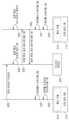
도 5를 참조하면, 본 발명의 일 실시예에 따른 통신 모듈(200)은 제1 통신 회로(210)와 제2 통신 회로(220), 안테나(ANT, 230), 및 컨트롤러(240) 등을 포함할 수 있다. 컨트롤러(240)는 제1 통신 회로(210) 또는 제2 통신 회로(220)를 이용하여 외부의 장치들과 데이터를 송수신할 수 있다. 일례로, 컨트롤러(240)는 제1 통신 회로(210)를 통해 블루투스 또는 BLE 로 외부 장치들과 통신하고, 제2 통신 회로(220)를 통해 Zigbee 또는 Z-Wave 로 외부 장치들과 통신할 수 있다. 일례로, 제1 통신 회로(210)와 제2 통신 회로(220)는 서로 같은 주파수 대역 또는 서로 다른 주파수 대역의 신호를 처리할 수 있다. 제1 통신 회로(210)와 제2 통신 회로(220)는 무선 신호를 송수신하기 위한 RF 회로를 포함할 수 있다.Referring to FIG. 5, a communication module (200) according to one embodiment of the present invention may include a first communication circuit (210), a second communication circuit (220), an antenna (ANT, 230), and a controller (240). The controller (240) may transmit and receive data with external devices using the first communication circuit (210) or the second communication circuit (220). For example, the controller (240) may communicate with external devices via Bluetooth or BLE through the first communication circuit (210), and may communicate with external devices via Zigbee or Z-Wave through the second communication circuit (220). For example, the first communication circuit (210) and the second communication circuit (220) may process signals of the same frequency band or different frequency bands. The first communication circuit (210) and the second communication circuit (220) may include an RF circuit for transmitting and receiving a wireless signal.
제1 통신 회로(210)와 제2 통신 회로(220)는 하나의 안테나(230)를 공유할 수 있다. 컨트롤러(240)는 제1 통신 회로(210)와 제2 통신 회로(220)가 안테나(230)를 점유하는 시간이 중복되지 않도록, 제1 통신 회로(210)와 제2 통신 회로(220)를 제어할 수 있다. 예를 들어, 컨트롤러(240)는 제1 통신 회로(210)와 제2 통신 회로(220) 중 하나만을 활성화하거나, 또는 제1 통신 회로(210)와 제2 통신 회로(220)를 모두 활성화시키고 제1 통신 회로(210)와 제2 통신 회로(220)를 시분할 방식으로 안테나(230)에 연결할 수 있다.The first communication circuit (210) and the second communication circuit (220) can share one antenna (230). The controller (240) can control the first communication circuit (210) and the second communication circuit (220) so that the time that the first communication circuit (210) and the second communication circuit (220) occupy the antenna (230) does not overlap. For example, the controller (240) can activate only one of the first communication circuit (210) and the second communication circuit (220), or can activate both the first communication circuit (210) and the second communication circuit (220) and connect the first communication circuit (210) and the second communication circuit (220) to the antenna (230) in a time-division manner.
도 5a를 참조하면, 컨트롤러(240)는 제1 통신 회로(210)와 안테나(230)를 이용하여 데이터를 송수신하는 동안, 제2 통신 회로(220)를 비활성화할 수 있다. 또한 도 5b를 참조하면, 컨트롤러(240)는 제2 통신 회로(220)와 안테나(230)를 이용하여 데이터를 송수신하는 동안 제1 통신 회로(210)를 비활성화할 수 있다. 즉, 제1 통신 방식으로 데이터를 송수신하는 모드에서 통신 모듈(200)은 도 5a와 같이 동작하고, 제2 통신 방식으로 데이터를 송수신하는 모드에서 통신 모듈(200)은 도 5b와 같이 동작할 수 있다.Referring to FIG. 5a, the controller (240) can deactivate the second communication circuit (220) while transmitting and receiving data using the first communication circuit (210) and the antenna (230). Also, referring to FIG. 5b, the controller (240) can deactivate the first communication circuit (210) while transmitting and receiving data using the second communication circuit (220) and the antenna (230). That is, in a mode for transmitting and receiving data using the first communication method, the communication module (200) can operate as in FIG. 5a, and in a mode for transmitting and receiving data using the second communication method, the communication module (200) can operate as in FIG. 5b.
또는, 컨트롤러(240)가 제1 통신 회로(210)와 제2 통신 회로(220)를 모두 활성화하고, 안테나(230)를 시분할 방식 등으로 제1 통신 회로(210)와 제2 통신 회로(220)에 연결할 수 있다. 통신 모듈(200)은 제1 통신 회로(210)가 안테나(230)를 점유하는 동안 제1 통신 방식으로 데이터를 송수신하고, 제2 통신 회로(220)가 안테나(230)를 점유하는 동안 제2 통신 방식으로 데이터를 송수신할 수 있다.Alternatively, the controller (240) may activate both the first communication circuit (210) and the second communication circuit (220) and connect the antenna (230) to the first communication circuit (210) and the second communication circuit (220) in a time-division manner, etc. The communication module (200) may transmit and receive data in the first communication manner while the first communication circuit (210) occupies the antenna (230), and may transmit and receive data in the second communication manner while the second communication circuit (220) occupies the antenna (230).
도 7 및 도 8은 본 발명의 일 실시예에 따른 조명 시스템의 동작을 설명하기 위해 제공되는 도면들이다.FIGS. 7 and 8 are drawings provided to explain the operation of a lighting system according to one embodiment of the present invention.
먼저 도 7을 참조하면, 조명 시스템(300)은 복수의 조명 장치들(311-314: 310)과 모바일 디바이스(320)를 포함할 수 있다. 복수의 조명 장치들(310)은 제1 조명 장치(311), 제2 조명 장치(312), 제3 조명 장치(313), 및 제4 조명 장치(314) 등을 포함할 수 있으며, 조명 장치들(310) 각각은 통신 모듈을 포함할 수 있다. 조명 장치들(310)의 개수는 한정적이지 않으며, 다양하게 증가, 감소할 수 있다. 통신 모듈은 서로 다른 제1 통신 방식과 제2 통신 방식을 지원할 수 있다. 조명 장치들(310) 각각에 포함되는 통신 모듈은 제1 통신 방식과 제2 통신 방식 중 하나를 이용하여 서로 통신할 수 있다. 일 실시예로, 조명 장치들(310) 각각에 포함되는 통신 모듈은, 제1 통신 방식에 의해 모바일 디바이스(320)나 다른 외부 장비의 개입 없이 서로 직접 통신할 수 있다.First, referring to FIG. 7, the lighting system (300) may include a plurality of lighting devices (311-314: 310) and a mobile device (320). The plurality of lighting devices (310) may include a first lighting device (311), a second lighting device (312), a third lighting device (313), a fourth lighting device (314), etc., and each of the lighting devices (310) may include a communication module. The number of the lighting devices (310) is not limited and may increase or decrease in various ways. The communication modules may support different first communication methods and second communication methods. The communication modules included in each of the lighting devices (310) may communicate with each other using one of the first communication method and the second communication method. In one embodiment, the communication modules included in each of the lighting devices (310) may communicate directly with each other without the intervention of the mobile device (320) or other external equipment by the first communication method.
모바일 디바이스(320)는 제1 통신 방식과 제2 통신 방식 중 어느 하나를 이용하여 조명 장치들(310) 중 적어도 하나와 직접 통신할 수 있다. 일 실시예로, 모바일 디바이스(320)는 제1 통신 방식을 이용하여 제1 조명 장치(311)와 직접 통신할 수 있다. 일례로, 제1 통신 방식은 블루투스 또는 BLE 일 수 있다. 조명 장치들(310)은 BLE 메쉬 방식으로 서로 직접 통신할 수 있다. 이하, 도 8을 참조하여 도 7에 도시한 조명 시스템(300)의 동작의 일 실시예를 더욱 자세히 설명하기로 한다.The mobile device (320) can communicate directly with at least one of the lighting devices (310) using either the first communication method or the second communication method. In one embodiment, the mobile device (320) can communicate directly with the first lighting device (311) using the first communication method. In one embodiment, the first communication method can be Bluetooth or BLE. The lighting devices (310) can communicate directly with each other using the BLE mesh method. Hereinafter, an embodiment of the operation of the lighting system (300) illustrated in FIG. 7 will be described in more detail with reference to FIG. 8.
도 8을 참조하면, 제1 조명 장치(311)의 통신 모듈(315)과 제2 조명 장치(312)의 통신 모듈(316)은 제1 통신 방식을 활성화하고(S10), 제2 통신 방식을 비활성화할 수 있다(S11). 일례로, 통신 모듈들(315, 316)은 제1 통신 방식을 지원하는 제1 통신 칩을 동작시키고 제2 통신 칩을 슬립 모드 (또는 대기 모드)에 진입시킬 수 있다. 또는, 통신 모듈들(315, 316)에서 제1 통신 방식을 지원하는 제1 통신 회로가 활성화되고 제2 통신 회로는 비활성화될 수 있다. 또한, 통신 모듈들(315, 316) 각각에 포함되는 하나의 통신 칩이 제1 통신 방식을 활성화하고 제2 통신 방식을 비활성화할 수도 있다.Referring to FIG. 8, the communication module (315) of the first lighting device (311) and the communication module (316) of the second lighting device (312) can activate the first communication method (S10) and deactivate the second communication method (S11). For example, the communication modules (315, 316) can operate the first communication chip supporting the first communication method and cause the second communication chip to enter a sleep mode (or standby mode). Alternatively, the first communication circuit supporting the first communication method in the communication modules (315, 316) can be activated and the second communication circuit can be deactivated. In addition, one communication chip included in each of the communication modules (315, 316) can activate the first communication method and deactivate the second communication method.
제1 조명 장치(311)의 통신 모듈(315)은 모바일 디바이스(320)에 제1 통신 방식에 의한 연결 요청을 송신할 수 있다(S12). 제1 통신 방식이 블루투스 또는 BLE 인 경우, S12 단계의 연결 요청은 페어링(PAIRING) 요청을 포함할 수 있다. 사용자는 모바일 디바이스(320)가 수신한 연결 요청을 확인하고 모바일 디바이스(320)를 조작하여 연결 요청에 응답할 수 있다. 사용자가 연결 요청에 응답하면, 제1 조명 장치(311)의 통신 모듈(315)은 제1 통신 방식에 의한 연결 응답을 수신하고(S13), 모바일 디바이스(320)와의 연결을 설정할 수 있다(S14). 모바일 디바이스(320) 역시 제1 조명 장치(311)와의 연결을 설정할 수 있다(S15).The communication module (315) of the first lighting device (311) can transmit a connection request to the mobile device (320) by the first communication method (S12). When the first communication method is Bluetooth or BLE, the connection request of step S12 can include a pairing request. The user can confirm the connection request received by the mobile device (320) and respond to the connection request by operating the mobile device (320). When the user responds to the connection request, the communication module (315) of the first lighting device (311) can receive a connection response by the first communication method (S13) and establish a connection with the mobile device (320) (S14). The mobile device (320) can also establish a connection with the first lighting device (311) (S15).
제1 조명 장치(311)와 모바일 디바이스(320) 사이의 연결은, 앞서 설명한 S12 내지 S15 단계와 달리 모바일 디바이스(320)가 제1 통신 방식에 의한 연결 요청을 제1 조명 장치(311)에 보냄으로써 설정될 수도 있다. 제1 조명 장치(311)는 사전에 미리 저장된 디바이스 목록을 확인하고, 디바이스 목록에 모바일 디바이스(320)가 존재하는 경우에 모바일 디바이스(320)와의 연결을 설정할 수 있다.The connection between the first lighting device (311) and the mobile device (320) may be established by the mobile device (320) sending a connection request by the first communication method to the first lighting device (311), unlike steps S12 to S15 described above. The first lighting device (311) may check a device list stored in advance, and establish a connection with the mobile device (320) if the mobile device (320) is present in the device list.
한편, 제1 조명 장치(311)의 통신 모듈(315)은 제2 조명 장치(312)의 통신 모듈(316)에 제1 통신 방식에 의한 연결 요청을 보낼 수 있다(S16). 제2 조명 장치(312)의 통신 모듈(316)은 S16 단계의 요청에 대응하여 제1 통신 방식에 의한 연결 응답을 제1 조명 장치(311)의 통신 모듈(315)로 전송할 수 있다(S17). 따라서, 제1 조명 장치(311)의 통신 모듈(315)이 제2 조명 장치(312)와의 연결을 설정하고(S18), 제2 조명 장치(312)의 통신 모듈(316)은 제1 조명 장치(311)와의 연결을 설정할 수 있다(S19).Meanwhile, the communication module (315) of the first lighting device (311) can send a connection request by the first communication method to the communication module (316) of the second lighting device (312) (S16). The communication module (316) of the second lighting device (312) can transmit a connection response by the first communication method to the communication module (315) of the first lighting device (311) in response to the request of step S16 (S17). Accordingly, the communication module (315) of the first lighting device (311) can establish a connection with the second lighting device (312) (S18), and the communication module (316) of the second lighting device (312) can establish a connection with the first lighting device (311) (S19).
도 7 및 도 8에 도시한 일 실시예에서, 조명 장치들(310)과 모바일 디바이스(320)는 하나의 통신 방식을 이용하여 서로 연결될 수 있다. 일례로, 블루투스 또는 BLE 에 의해 조명 장치들(310) 중 적어도 하나와 모바일 디바이스(320)가 서로 직접 통신할 수 있다. 또한, 조명 장치들(310)은 BLE 메쉬 네트워크를 이용하여 서로 통신할 수 있다.In one embodiment illustrated in FIGS. 7 and 8, the lighting devices (310) and the mobile device (320) may be connected to each other using one communication method. For example, at least one of the lighting devices (310) and the mobile device (320) may communicate directly with each other via Bluetooth or BLE. Additionally, the lighting devices (310) may communicate with each other using a BLE mesh network.
사용자는 모바일 디바이스(320)에서 실행 가능한 애플리케이션을 이용하여 조명 장치들(310)을 제어하거나, 조명 장치들(310)의 정보, 예를 들어 조명 장치들(310)의 상태, 소모 전력, 이상 발생 여부 등을 확인할 수 있다. 사용자가 상기 애플리케이션을 통해 입력하는 제어 커맨드는, 모바일 디바이스(320)와 직접 연결된 제1 조명 장치(311)에 전달되며, 제1 조명 장치(311)는 조명 장치들(310) 중에서 사용자가 제어하고자 하는 장치를 식별하여 제어 커맨드를 전달할 수 있다. 제1 조명 장치(311)는 다른 조명 장치들(312-314)에 제어 커맨드를 전달할 때, 앞서 설명한 BLE 메쉬 네트워크를 이용할 수 있다.The user can control the lighting devices (310) or check information of the lighting devices (310), such as the status of the lighting devices (310), power consumption, and occurrence of an abnormality, using an application executable on the mobile device (320). The control command that the user inputs through the application is transmitted to the first lighting device (311) directly connected to the mobile device (320), and the first lighting device (311) can identify a device that the user wants to control among the lighting devices (310) and transmit the control command. When transmitting the control command to other lighting devices (312-314), the first lighting device (311) can use the BLE mesh network described above.
도 9 및 도 10은 본 발명의 일 실시예에 따른 조명 시스템의 동작을 설명하기 위해 제공되는 도면들이다.FIGS. 9 and 10 are drawings provided to explain the operation of a lighting system according to one embodiment of the present invention.
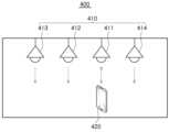
도 9를 참조하면, 조명 시스템(400)은 복수의 조명 장치들(411-414: 410)과 모바일 디바이스(320)를 포함할 수 있다. 복수의 조명 장치들(410)은 제1 내지 제4 조명 장치들(411-414)을 포함할 수 있으며, 조명 장치들(410) 각각은 통신 모듈을 포함할 수 있다. 조명 장치들(410)의 개수는 필요에 따라 다양하게 변경될 수 있다. 조명 장치들(410) 각각에 포함되는 통신 모듈은 서로 다른 제1 통신 방식과 제2 통신 방식을 지원할 수 있다.Referring to FIG. 9, the lighting system (400) may include a plurality of lighting devices (411-414: 410) and a mobile device (320). The plurality of lighting devices (410) may include first to fourth lighting devices (411-414), and each of the lighting devices (410) may include a communication module. The number of the lighting devices (410) may vary depending on the need. The communication module included in each of the lighting devices (410) may support different first communication methods and second communication methods.
모바일 디바이스(420)는 스마트폰, 태블릿 PC 등의 장치일 수 있으며, 제1 통신 방식과 제2 통신 방식 중 어느 하나를 이용하여 조명 장치들(410) 중 적어도 하나와 직접 통신할 수 있다. 일 실시예로, 모바일 디바이스(420)는 제1 통신 방식을 이용하여 제1 조명 장치(411)와 직접 통신할 수 있다. 일례로, 제1 통신 방식은 블루투스 또는 BLE 일 수 있다. 또한 도 9에 도시한 일 실시예에서, 제2 내지 제4 조명 장치들(412-414)의 통신 모듈은 BLE 비콘 모드로 동작할 수 있다. 일례로, 제2 내지 제4 조명 장치들(412-414)의 통신 모듈은 특정 이벤트가 발생하는 경우에, BLE 비콘 모드를 이용하여 모바일 디바이스(420)에 데이터를 전송할 수 있다. 상기 이벤트는, 제2 내지 제4 조명 장치들(412-414)의 유지/보수에 필요한 정보, 및 고장 정보 등을 포함할 수 있다.The mobile device (420) may be a device such as a smart phone or a tablet PC, and may directly communicate with at least one of the lighting devices (410) using either the first communication method or the second communication method. In one embodiment, the mobile device (420) may directly communicate with the first lighting device (411) using the first communication method. For example, the first communication method may be Bluetooth or BLE. In addition, in one embodiment illustrated in FIG. 9, the communication modules of the second to fourth lighting devices (412-414) may operate in a BLE beacon mode. For example, the communication modules of the second to fourth lighting devices (412-414) may transmit data to the mobile device (420) using the BLE beacon mode when a specific event occurs. The event may include information necessary for maintenance/repair of the second to fourth lighting devices (412-414), failure information, etc.
이하, 도 10을 참조하여 도 9에 도시한 조명 시스템(400)의 동작의 일 실시예를 더욱 자세히 설명하기로 한다.Hereinafter, an embodiment of the operation of the lighting system (400) illustrated in FIG. 9 will be described in more detail with reference to FIG. 10.
도 10을 참조하면, 제1 조명 장치(411)의 통신 모듈(415)은 제1 통신 방식을 활성화하고(S20), 제2 통신 방식을 비활성화할 수 있다(S21). 일례로, 제1 조명 장치(411)의 통신 모듈(415)은 제1 통신 방식을 지원하는 제1 통신 칩을 동작시키고 제2 통신 칩을 슬립 모드 (또는 대기 모드)에 진입시킬 수 있다. 또는, 통신 모듈(415)에서 제1 통신 방식을 지원하는 제1 통신 회로가 활성화되고 제2 통신 회로는 비활성화될 수 있다. 또한, 통신 모듈들(415, 416) 각각에 포함되는 하나의 통신 칩이 제1 통신 방식을 활성화하고 제2 통신 방식을 비활성화할 수도 있다.Referring to FIG. 10, the communication module (415) of the first lighting device (411) can activate the first communication method (S20) and deactivate the second communication method (S21). For example, the communication module (415) of the first lighting device (411) can operate the first communication chip supporting the first communication method and cause the second communication chip to enter a sleep mode (or standby mode). Alternatively, the first communication circuit supporting the first communication method in the communication module (415) can be activated and the second communication circuit can be deactivated. In addition, one communication chip included in each of the communication modules (415, 416) can activate the first communication method and deactivate the second communication method.
제1 조명 장치(411)의 통신 모듈(415)은 모바일 디바이스(420)에 제1 통신 방식에 의한 연결 요청을 송신할 수 있다(S22). 제1 통신 방식이 블루투스 또는 BLE 인 경우, S22 단계의 연결 요청은 페어링(PAIRING) 요청을 포함할 수 있다. 사용자는 모바일 디바이스(420)가 수신한 연결 요청을 확인하고 모바일 디바이스(420)를 조작하여 연결 요청에 응답할 수 있다. 사용자가 연결 요청에 응답하면, 제1 조명 장치(411)의 통신 모듈(415)은 제1 통신 방식에 의한 연결 응답을 수신하고(S23), 모바일 디바이스(420)와의 연결을 설정할 수 있다(S24). 모바일 디바이스(420) 역시 제1 조명 장치(411)와의 연결을 설정할 수 있다(S25).The communication module (415) of the first lighting device (411) can transmit a connection request by the first communication method to the mobile device (420) (S22). If the first communication method is Bluetooth or BLE, the connection request in step S22 can include a pairing request. The user can confirm the connection request received by the mobile device (420) and respond to the connection request by operating the mobile device (420). If the user responds to the connection request, the communication module (415) of the first lighting device (411) can receive a connection response by the first communication method (S23) and establish a connection with the mobile device (420) (S24). The mobile device (420) can also establish a connection with the first lighting device (411) (S25).
제1 조명 장치(411)와 모바일 디바이스(420) 사이의 연결은, 앞서 설명한 S22 내지 S25 단계와 달리 모바일 디바이스(420)가 제1 통신 방식에 의한 연결 요청을 제1 조명 장치(411)에 먼저 보냄으로써 설정될 수도 있다. 제1 조명 장치(411)는 사전에 미리 저장된 디바이스 목록을 확인하고, 디바이스 목록에 모바일 디바이스(420)가 존재하는 경우에 모바일 디바이스(420)와의 연결을 설정할 수 있다.The connection between the first lighting device (411) and the mobile device (420) may be established by the mobile device (420) first sending a connection request by the first communication method to the first lighting device (411), unlike steps S22 to S25 described above. The first lighting device (411) can check a device list stored in advance and establish a connection with the mobile device (420) if the mobile device (420) is present in the device list.
한편, 제2 조명 장치(412)의 통신 모듈(416)은 제1 통신 방식의 비콘 모드를 활성화하고(S26), 제2 통신 방식을 비활성화할 수 있다(S27). 제2 조명 장치(412)의 통신 모듈(416)은, 소정의 이벤트가 발생하거나 또는 미리 설정된 주기가 도래할 때마다 모바일 디바이스(420)에 비콘 모드로 데이터를 전송할 수 있다(S28). 사용자는 모바일 디바이스(420)를 이용하여 제1 조명 장치(411)를 제어하고, 비콘 모드를 이용하여 제2 조명 장치(412) 등의 동작 상태와 고장 발생 여부 등을 인지할 수 있다.Meanwhile, the communication module (416) of the second lighting device (412) can activate the beacon mode of the first communication method (S26) and deactivate the second communication method (S27). The communication module (416) of the second lighting device (412) can transmit data to the mobile device (420) in the beacon mode whenever a predetermined event occurs or a preset cycle arrives (S28). The user can control the first lighting device (411) using the mobile device (420) and recognize the operating status and whether a failure has occurred of the second lighting device (412) using the beacon mode.
도 11 및 도 12는 본 발명의 일 실시예에 따른 조명 시스템의 동작을 설명하기 위해 제공되는 도면들이다.FIGS. 11 and 12 are drawings provided to explain the operation of a lighting system according to one embodiment of the present invention.
도 11을 참조하면, 조명 시스템(500)은 복수의 조명 장치들(511-514: 510)과 모바일 디바이스(520)를 포함할 수 있다. 복수의 조명 장치들(510)은 제1 내지 제4 조명 장치(511-514) 등을 포함할 수 있으며, 조명 장치들(510) 각각은 통신 모듈을 포함할 수 있다. 조명 장치들(510)의 개수는 한정적이지 않으며, 다양하게 변형될 수 있다. 통신 모듈은 서로 다른 제1 통신 방식과 제2 통신 방식을 지원할 수 있다. 조명 장치들(510) 각각에 포함되는 통신 모듈은 제1 통신 방식과 제2 통신 방식 중 하나를 이용하여 서로 통신할 수 있다.Referring to FIG. 11, a lighting system (500) may include a plurality of lighting devices (511-514: 510) and a mobile device (520). The plurality of lighting devices (510) may include first to fourth lighting devices (511-514), etc., and each of the lighting devices (510) may include a communication module. The number of the lighting devices (510) is not limited and may be variously modified. The communication modules may support different first communication methods and second communication methods. The communication modules included in each of the lighting devices (510) may communicate with each other using one of the first communication method and the second communication method.
도 11에 도시한 일 실시예에서, 모바일 디바이스(520)는 제1 통신 방식과 제2 통신 방식 중 어느 하나를 이용하여 조명 장치들(510) 중 적어도 하나와 직접 통신할 수 있다. 일 실시예로, 모바일 디바이스(520)는 제1 통신 방식을 이용하여 제1 조명 장치(511)와 직접 통신할 수 있다. 일례로, 제1 통신 방식은 블루투스 또는 BLE 일 수 있다. 제1 조명 장치(511)를 제외한 제2 내지 제4 조명 장치들(512-514)의 통신 모듈은 BLE 비콘 모드를 활성화하여 모바일 디바이스(520)에 데이터를 전송할 수 있다.In one embodiment illustrated in FIG. 11, the mobile device (520) can communicate directly with at least one of the lighting devices (510) using either the first communication method or the second communication method. In one embodiment, the mobile device (520) can communicate directly with the first lighting device (511) using the first communication method. For example, the first communication method may be Bluetooth or BLE. The communication modules of the second to fourth lighting devices (512-514), excluding the first lighting device (511), can activate the BLE beacon mode to transmit data to the mobile device (520).
조명 장치들(510)은 제2 통신 방식으로 게이트웨이(530)를 통해 서로 통신 가능하도록 연결될 수 있다. 일례로 제2 통신 방식은 Zigbee 또는 Z-Wave 일 수 있다. 또는, 조명 장치들(510) 중 적어도 하나가 제2 통신 방식으로 게이트웨이(530)에 연결되고, 조명 장치들(510)이 서로 제2 통신 방식으로 연결될 수도 있다. 이 경우, 조명 장치들(510)에 포함되는 통신 모듈은 Zigbee 라우터(router)로 동작할 수 있다. 도 11에 도시한 일 실시예에서, 조명 장치들(510)에 포함되는 통신 모듈은 제1 통신 방식과 제2 통신 방식을 모두 활성화시킬 수 있다.The lighting devices (510) may be connected to each other via the gateway (530) in a second communication manner. For example, the second communication manner may be Zigbee or Z-Wave. Alternatively, at least one of the lighting devices (510) may be connected to the gateway (530) in the second communication manner, and the lighting devices (510) may be connected to each other in the second communication manner. In this case, the communication module included in the lighting devices (510) may operate as a Zigbee router. In one embodiment illustrated in FIG. 11, the communication module included in the lighting devices (510) may activate both the first communication manner and the second communication manner.
이하, 도 12를 참조하여 도 10에 도시한 조명 시스템(500)의 동작의 일 실시예를 더욱 자세히 설명하기로 한다.Hereinafter, with reference to FIG. 12, one embodiment of the operation of the lighting system (500) illustrated in FIG. 10 will be described in more detail.
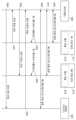
도 12를 참조하면, 제1 조명 장치(511)의 통신 모듈(515)과 제2 조명 장치(512)의 통신 모듈(516)은 게이트웨이(530)와 제2 통신 방식으로 연결될 수 있다(S30, S31). 또는 실시예들에 따라 제1 조명 장치(511)의 통신 모듈(515)은 게이트웨이(530)와 연결되고, 제2 조명 장치(512)의 통신 모듈(516)은 제2 통신 방식에 의해 제1 조명 장치(511)의 통신 모듈(515)과 연결될 수 있다. 한편, 제1 조명 장치(511)의 통신 모듈(515)은 제1 통신 방식을 활성화하고(S32), 제2 조명 장치(512)의 통신 모듈(516)은 제1 통신 방식을 비콘 모드로 활성화할 수 있다(S33).Referring to FIG. 12, the communication module (515) of the first lighting device (511) and the communication module (516) of the second lighting device (512) may be connected to the gateway (530) in a second communication manner (S30, S31). Or, according to embodiments, the communication module (515) of the first lighting device (511) may be connected to the gateway (530), and the communication module (516) of the second lighting device (512) may be connected to the communication module (515) of the first lighting device (511) in a second communication manner. Meanwhile, the communication module (515) of the first lighting device (511) may activate the first communication manner (S32), and the communication module (516) of the second lighting device (512) may activate the first communication manner in a beacon mode (S33).
제1 조명 장치(511)의 통신 모듈(515)은 모바일 디바이스(520)와 제1 통신 방식으로 직접 연결될 수 있다(S34). 제1 조명 장치(511)의 통신 모듈(515)과 모바일 디바이스(520) 사이의 연결을 설정하는 방법은, 앞서 설명한 바와 유사할 수 있다. 예를 들어, 제1 조명 장치(511)의 통신 모듈(515)과 모바일 디바이스(520) 중 하나가 먼저 연결 요청을 보내고, 나머지 하나가 이에 응답하면, 제1 조명 장치(511)의 통신 모듈(515)과 모바일 디바이스(520) 사이에 제1 통신 방식에 의한 통신 채널이 형성될 수 있다.The communication module (515) of the first lighting device (511) can be directly connected to the mobile device (520) via the first communication method (S34). The method of establishing a connection between the communication module (515) of the first lighting device (511) and the mobile device (520) can be similar to that described above. For example, when one of the communication module (515) of the first lighting device (511) and the mobile device (520) first sends a connection request, and the other one responds to it, a communication channel via the first communication method can be formed between the communication module (515) of the first lighting device (511) and the mobile device (520).
제2 조명 장치(512)의 통신 모듈(516)은 제2 통신 방식의 비콘 모드를 이용하여 모바일 디바이스(520)에 데이터를 전송할 수 있다(S35). 일 실시예에서 제2 조명 장치(512)는 소정의 이벤트가 발생하거나, 미리 설정된 주기가 도래할 때마다 모바일 디바이스(520)에 데이터를 전송할 수 있다. 데이터는 제2 조명 장치(512)의 상태 정보, 소모 전력, 사용 시간 등을 포함할 수 있다.The communication module (516) of the second lighting device (512) can transmit data to the mobile device (520) using the beacon mode of the second communication method (S35). In one embodiment, the second lighting device (512) can transmit data to the mobile device (520) whenever a predetermined event occurs or a preset cycle arrives. The data can include status information, power consumption, usage time, etc. of the second lighting device (512).
도 11 및 도 12를 참조하여 설명한 일 실시예에서, 조명 장치들(510)에 포함되는 통신 모듈은 제1 통신 방식과 제2 통신 방식을 모두 활성화시킬 수 있다. 통신 모듈이 하나의 안테나만을 포함하는 경우, 시분할 방식 등으로 안테나를 제1 통신 방식과 제2 통신 방식에 할당할 수 있다. 일례로, 제1 조명 장치(511)의 통신 모듈(515)은 모바일 디바이스(520)와 제1 통신 방식에 의한 직접 연결이 설정되는 동안, 안테나를 제1 통신 방식에만 할당할 수 있다. 제1 조명 장치(511)의 통신 모듈(515)은 모바일 디바이스(520)와의 연결이 끊어지면, 안테나를 제2 통신 방식에 할당하여 게이트웨이(530)와의 통신 채널을 형성할 수 있다.In one embodiment described with reference to FIGS. 11 and 12, the communication module included in the lighting devices (510) can activate both the first communication mode and the second communication mode. When the communication module includes only one antenna, the antenna can be assigned to the first communication mode and the second communication mode in a time-division manner, etc. For example, the communication module (515) of the first lighting device (511) can assign the antenna only to the first communication mode while a direct connection is established with the mobile device (520) via the first communication mode. When the connection with the mobile device (520) is lost, the communication module (515) of the first lighting device (511) can assign the antenna to the second communication mode to form a communication channel with the gateway (530).
도 13 및 도 14는 본 발명의 일 실시예에 따른 조명 시스템의 동작을 설명하기 위해 제공되는 도면들이다.FIGS. 13 and 14 are drawings provided to explain the operation of a lighting system according to one embodiment of the present invention.
도 13을 참조하면, 조명 시스템(600)은 조명 장치들(611-614: 610)과 모바일 디바이스(620) 및 게이트웨이(630)를 포함할 수 있다. 조명 장치들(610)은 서로 다른 제1 통신 방식 및 제2 통신 방식을 지원하는 통신 모듈을 포함할 수 있으며, 제2 통신 방식에 의해 게이트웨이(630)와 통신할 수 있다. 일례로 제1 통신 방식은 블루투스, BLE 등일 수 있으며, 제2 통신 방식은 Zigbee, Z-wave, Wifi 등일 수 있다. 게이트웨이(630)는 제2 통신 방식에 의해 조명 장치들(610)과 통신할 수 있다. 조명 장치들(610)의 통신 모듈은 Zigbee 라우터로 동작할 수 있으며, Zigbee 통신에 의해 서로 통신 가능하도록 연결될 수 있다.Referring to FIG. 13, the lighting system (600) may include lighting devices (611-614: 610), a mobile device (620), and a gateway (630). The lighting devices (610) may include communication modules that support different first and second communication methods, and may communicate with the gateway (630) via the second communication method. For example, the first communication method may be Bluetooth, BLE, etc., and the second communication method may be Zigbee, Z-wave, Wifi, etc. The gateway (630) may communicate with the lighting devices (610) via the second communication method. The communication modules of the lighting devices (610) may operate as Zigbee routers, and may be connected to communicate with each other via Zigbee communication.
한편, 게이트웨이(630)는 제1 통신 방식 및 제2 통신 방식과 다른 제3 통신 방식에 의해 모바일 디바이스(620)와 연결될 수 있다. 일례로, 제1 통신 방식이 블루투스 또는 BLE 이고, 제2 통신 방식이 Zigbee 인 경우, 제3 통신 방식은 Wifi일 수 있다. 게이트웨이(630)는 별도의 액세스 포인트(Access Point)를 통해 모바일 디바이스(620)와 Wifi 통신으로 연결될 수도 있다.Meanwhile, the gateway (630) may be connected to the mobile device (620) by a third communication method that is different from the first and second communication methods. For example, if the first communication method is Bluetooth or BLE and the second communication method is Zigbee, the third communication method may be Wifi. The gateway (630) may also be connected to the mobile device (620) by Wifi communication through a separate access point.
모바일 디바이스(620)에서 생성되는 제어 커맨드는 게이트웨이(630)를 통해 조명 장치들(610) 중 적어도 하나에 전달될 수 있다. 게이트웨이(630)는 제3 통신 방식에 의해 모바일 디바이스(620)로부터 수신한 제어 커맨드를, 제2 통신 방식에 맞는 포맷으로 변환하여 조명 장치들(610) 중 적어도 하나에 전달할 수 있다. 이하, 도 14를 참조하여 도 13에 도시한 조명 시스템(600)의 동작의 일 실시예를 더욱 자세히 설명하기로 한다.A control command generated from a mobile device (620) can be transmitted to at least one of the lighting devices (610) via a gateway (630). The gateway (630) can convert a control command received from the mobile device (620) via a third communication method into a format suitable for the second communication method and transmit it to at least one of the lighting devices (610). Hereinafter, an embodiment of the operation of the lighting system (600) illustrated in FIG. 13 will be described in more detail with reference to FIG. 14.
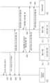
도 14를 참조하면, 제1 조명 장치(611)의 통신 모듈(615)과 제2 조명 장치(612)의 통신 모듈(616)은 게이트웨이(630)와 제2 통신 방식으로 연결될 수 있다(S40, S41). 또는 실시예들에 따라 조명 장치들(610) 중 적어도 하나가 게이트웨이(630)와 제2 통신 방식으로 연결되고, 조명 장치들(610)이 서로 제2 통신 방식으로 연결될 수도 있다. 즉, 조명 장치들(610)의 통신 모듈이 제2 통신 방식의 라우터 기능을 제공할 수도 있다.Referring to FIG. 14, the communication module (615) of the first lighting device (611) and the communication module (616) of the second lighting device (612) may be connected to the gateway (630) in a second communication manner (S40, S41). Alternatively, according to embodiments, at least one of the lighting devices (610) may be connected to the gateway (630) in a second communication manner, and the lighting devices (610) may be connected to each other in the second communication manner. That is, the communication modules of the lighting devices (610) may provide a router function of the second communication manner.
게이트웨이(630)는 제3 통신 방식에 의해 모바일 디바이스(620)와 통신 가능하도록 연결될 수 있다(S42). 게이트웨이(630)는 Wifi 통신을 통해 직접 모바일 디바이스(620)와 연결되거나, 모바일 디바이스(620)가 연결된 이동통신망을 통해 모바일 디바이스(620)와 통신 가능하도록 연결되거나, 또는 게이트웨이(630)에 연결된 액세스 포인트 등을 통해 모바일 디바이스(620)와 연결될 수 있다. 한편, 제1 조명 장치(611)의 통신 모듈(615)과 제2 조명 장치(612)의 통신 모듈(616)은 제1 통신 방식을 비콘 모드로 활성화할 수 있다(S43, S44).The gateway (630) can be connected to communicate with the mobile device (620) by the third communication method (S42). The gateway (630) can be directly connected to the mobile device (620) via Wifi communication, can be connected to communicate with the mobile device (620) via a mobile communication network to which the mobile device (620) is connected, or can be connected to the mobile device (620) via an access point, etc. connected to the gateway (630). Meanwhile, the communication module (615) of the first lighting device (611) and the communication module (616) of the second lighting device (612) can activate the first communication method in a beacon mode (S43, S44).
모바일 디바이스(620)는 제어 커맨드를 생성하고, 제3 통신 방식에 의해 상기 제어 커맨드를 게이트웨이(630)에 전송할 수 있다(S45). 게이트웨이(630)는 모바일 디바이스(620)로부터 수신한 제어 커맨드를, 제2 통신 방식에 맞는 포맷으로 변환하여 타겟 조명 장치에 전송할 수 있다(S46). 도 14에 도시한 일 실시예에서 타겟 조명 장치는 제2 조명 장치(612)일 수 있다. 제2 조명 장치(612)는 통신 모듈(616)을 통해 제어 커맨드를 수신하고, 제어 커맨드에 기초하여 광원의 밝기, 조명 시간 등을 조절할 수 있다.The mobile device (620) can generate a control command and transmit the control command to the gateway (630) via the third communication method (S45). The gateway (630) can convert the control command received from the mobile device (620) into a format suitable for the second communication method and transmit it to the target lighting device (S46). In one embodiment illustrated in FIG. 14, the target lighting device can be the second lighting device (612). The second lighting device (612) can receive the control command via the communication module (616) and adjust the brightness of the light source, lighting time, etc. based on the control command.
한편, 조명 장치들(610) 중 적어도 하나는, 소정의 이벤트가 발생하거나 미리 설정된 주기가 도래할 때 장치 정보를 생성하여 게이트웨이(630)로 전송할 수 있다(S47). 조명 장치들(610)은 제2 통신 방식을 이용하여 게이트웨이(630)에 장치 정보를 전송할 수 있다. 게이트웨이(630)는 S47 단계에서 수신한 장치 정보를 제3 통신 방식에 맞는 포맷으로 변환하여 모바일 디바이스(620)에 전송할 수 있다(S48). 사용자는 모바일 디바이스(620)를 통해, 조명 장치들(610)의 상태 정보, 소모 전력, 사용 시간 등을 인지할 수 있다.Meanwhile, at least one of the lighting devices (610) can generate device information and transmit it to the gateway (630) when a predetermined event occurs or a preset cycle arrives (S47). The lighting devices (610) can transmit the device information to the gateway (630) using the second communication method. The gateway (630) can convert the device information received in step S47 into a format suitable for the third communication method and transmit it to the mobile device (620) (S48). The user can recognize the status information, power consumption, usage time, etc. of the lighting devices (610) through the mobile device (620).
즉, 도 13 및 도 14를 참조하여 설명한 일 실시예에 따른 조명 시스템(600)에서는, 모바일 디바이스(620)가 게이트웨이(630)를 통해 조명 장치들(610)에 제어 커맨드를 전송하고, 게이트웨이(630)를 통해 조명 장치들(610)로부터 정보를 수집할 수 있다. 게이트웨이(630)와 조명 장치들(610)을 연결하는 통신 방식과, 게이트웨이(630)와 모바일 디바이스(620)를 연결하는 통신 방식은 서로 다를 수 있다.That is, in the lighting system (600) according to one embodiment described with reference to FIGS. 13 and 14, the mobile device (620) can transmit a control command to the lighting devices (610) through the gateway (630) and collect information from the lighting devices (610) through the gateway (630). The communication method connecting the gateway (630) and the lighting devices (610) and the communication method connecting the gateway (630) and the mobile device (620) may be different from each other.
도 15 및 도 16은 본 발명의 일 실시예에 따른 조명 시스템의 동작을 설명하기 위해 제공되는 도면들이다.FIGS. 15 and 16 are drawings provided to explain the operation of a lighting system according to one embodiment of the present invention.
도 15를 참조하면, 조명 시스템(700)은 조명 장치들(711-714: 710)과 모바일 디바이스(720) 및 게이트웨이(730)를 포함할 수 있다. 조명 장치들(610)은 서로 다른 제1 통신 방식 및 제2 통신 방식을 지원하는 통신 모듈을 포함할 수 있으며, 제2 통신 방식에 의해 게이트웨이(630)와 통신할 수 있다. 일례로 제1 통신 방식은 블루투스, BLE 등일 수 있으며, 제2 통신 방식은 Zigbee, Z-wave, Wifi 등일 수 있다. 게이트웨이(730)는 제2 통신 방식에 의해 조명 장치들(710)과 통신할 수 있다. 일례로, 조명 장치들(610)의 통신 모듈은 Zigbee 라우터로 동작할 수 있으며, Zigbee 통신에 의해 서로 통신 가능하도록 연결될 수 있다.Referring to FIG. 15, the lighting system (700) may include lighting devices (711-714: 710), a mobile device (720), and a gateway (730). The lighting devices (610) may include communication modules that support different first and second communication methods, and may communicate with the gateway (630) via the second communication method. For example, the first communication method may be Bluetooth, BLE, etc., and the second communication method may be Zigbee, Z-wave, Wifi, etc. The gateway (730) may communicate with the lighting devices (710) via the second communication method. For example, the communication modules of the lighting devices (610) may operate as Zigbee routers, and may be connected to communicate with each other via Zigbee communication.
조명 장치들(710) 중 적어도 하나는, 제1 통신 방식에 의해 모바일 디바이스(720)와 직접 통신 가능하도록 연결될 수 있다. 도 15에 도시한 일 실시예에서는, 제1 조명 장치(711)가 모바일 디바이스(720)와 제1 통신 방식에 의해 직접 연결될 수 있다. 한편, 제2 내지 제4 조명 장치들(712-714)은 제1 통신 방식의 비콘 모드로 동작하여, 모바일 디바이스(720)로 데이터를 전송할 수 있다.At least one of the lighting devices (710) may be connected to directly communicate with the mobile device (720) via the first communication method. In one embodiment illustrated in FIG. 15, the first lighting device (711) may be directly connected to the mobile device (720) via the first communication method. Meanwhile, the second to fourth lighting devices (712-714) may operate in a beacon mode of the first communication method to transmit data to the mobile device (720).
도 15에 도시한 일 실시예에서, 조명 장치들(710)의 통신 모듈은 제1 통신 방식과 제2 통신 방식을 모두 활성화할 수 있다. 따라서, 통신 모듈이 하나의 안테나만을 포함하는 경우, 통신 모듈은 시분할 방식 등으로 안테나를 제1 통신 방식과 제2 통신 방식에 할당하여 충돌을 방지할 수 있다.In one embodiment illustrated in Fig. 15, the communication module of the lighting devices (710) can activate both the first communication mode and the second communication mode. Accordingly, when the communication module includes only one antenna, the communication module can prevent collision by allocating the antenna to the first communication mode and the second communication mode in a time-division manner, etc.
한편, 게이트웨이(730)는 제1 통신 방식 및 제2 통신 방식과 다른 제3 통신 방식에 의해 모바일 디바이스(720)와 연결될 수 있다. 일례로, 제1 통신 방식이 블루투스 또는 BLE 이고, 제2 통신 방식이 Zigbee 인 경우, 제3 통신 방식은 Wifi일 수 있다. 예를 들어, 게이트웨이(730)는 별도의 액세스 포인트(Access Point)를 통해 모바일 디바이스(720)와 Wifi 통신으로 연결될 수도 있다.Meanwhile, the gateway (730) may be connected to the mobile device (720) by a third communication method that is different from the first and second communication methods. For example, if the first communication method is Bluetooth or BLE and the second communication method is Zigbee, the third communication method may be Wifi. For example, the gateway (730) may be connected to the mobile device (720) by Wifi communication through a separate access point.
도 15에 도시한 일 실시예에서는, 조명 장치들(710)의 통신 모듈에서 제1 통신 방식과 제2 통신 방식이 모두 활성화되므로, 조명 장치들(710)이 제1 통신 방식을 통해 모바일 디바이스(720)로부터 제어 커맨드를 직접 수신하거나, 또는 게이트웨이(730)를 통해 제2 통신 방식으로 제어 커맨드를 수신할 수도 있다. 예를 들어, 모바일 디바이스(720)와 제1 통신 방식으로 직접 연결되는 제1 통신 장치(711)가 모바일 디바이스(720)로부터 제어 커맨드를 수신할 수 있다. 제1 통신 장치(711)는 제1 통신 방식으로 수신한 제어 커맨드를 제2 통신 방식에 맞는 포맷으로 변환하여 다른 조명 장치들(712-714)에 전달할 수 있다. 또는, 게이트웨이(730)가 모바일 디바이스(720)로부터 제3 통신 방식으로 제어 커맨드를 수신하고, 제어 커맨드를 제2 통신 방식에 맞는 포맷으로 변환하여 조명 장치들(710)에 전달할 수도 있다.In one embodiment illustrated in FIG. 15, since both the first communication method and the second communication method are activated in the communication modules of the lighting devices (710), the lighting devices (710) may directly receive a control command from the mobile device (720) via the first communication method, or may receive a control command via the second communication method via the gateway (730). For example, a first communication device (711) directly connected to the mobile device (720) via the first communication method may receive a control command from the mobile device (720). The first communication device (711) may convert the control command received via the first communication method into a format suitable for the second communication method and transmit it to other lighting devices (712-714). Alternatively, the gateway (730) may receive a control command via the third communication method from the mobile device (720), convert the control command into a format suitable for the second communication method, and transmit it to the lighting devices (710).
이하, 도 16을 참조하여 도 15에 도시한 조명 시스템(700)의 동작의 일 실시예를 더욱 자세히 설명하기로 한다.Hereinafter, with reference to FIG. 16, one embodiment of the operation of the lighting system (700) illustrated in FIG. 15 will be described in more detail.
도 16을 참조하면, 제1 조명 장치(711)의 통신 모듈(715)과 제2 조명 장치(712)의 통신 모듈(716)이 게이트웨이(730)와 제2 통신 방식으로 연결될 수 있다(S50, S51). 또는 실시예들에 따라 조명 장치들(710) 중 적어도 하나가 게이트웨이(730)와 제2 통신 방식으로 연결되고, 조명 장치들(710)이 서로 제2 통신 방식으로 연결될 수도 있다. 즉, 조명 장치들(710)의 통신 모듈이 제2 통신 방식의 라우터 기능을 제공할 수도 있다.Referring to FIG. 16, the communication module (715) of the first lighting device (711) and the communication module (716) of the second lighting device (712) may be connected to the gateway (730) in a second communication manner (S50, S51). Alternatively, according to embodiments, at least one of the lighting devices (710) may be connected to the gateway (730) in a second communication manner, and the lighting devices (710) may be connected to each other in the second communication manner. That is, the communication modules of the lighting devices (710) may provide a router function of the second communication manner.
제1 조명 장치(711)의 통신 모듈(715)은 제1 통신 방식을 활성화하고(S52), 제2 조명 장치(712)의 통신 모듈(716)은 제1 통신 방식을 비콘 모드로 활성화할 수 있다(S53). 즉, 도 15 및 도 16에 도시한 일 실시예에서는, 통신 모듈들(715, 716)이 제1 통신 방식과 제2 통신 방식을 모두 활성화할 수 있다.The communication module (715) of the first lighting device (711) can activate the first communication mode (S52), and the communication module (716) of the second lighting device (712) can activate the first communication mode in a beacon mode (S53). That is, in one embodiment illustrated in FIGS. 15 and 16, the communication modules (715, 716) can activate both the first communication mode and the second communication mode.
게이트웨이(730)는 제3 통신 방식에 의해 모바일 디바이스(720)와 통신 가능하도록 연결될 수 있다(S54). 게이트웨이(730)는 Wifi 통신을 통해 직접 모바일 디바이스(720)와 연결되거나, 모바일 디바이스(720)가 연결된 이동통신망을 통해 모바일 디바이스(720)와 통신 가능하도록 연결되거나, 또는 게이트웨이(730)에 연결된 액세스 포인트 등을 통해 모바일 디바이스(720)와 연결될 수 있다. 제3 통신 방식은 제2 통신 방식과 다른 통신 방식일 수 있다.The gateway (730) may be connected to communicate with the mobile device (720) via a third communication method (S54). The gateway (730) may be directly connected to the mobile device (720) via Wifi communication, may be connected to communicate with the mobile device (720) via a mobile communication network to which the mobile device (720) is connected, or may be connected to the mobile device (720) via an access point connected to the gateway (730). The third communication method may be a different communication method from the second communication method.
모바일 디바이스(720)는, 제1 통신 방식이 활성화된 제1 조명 장치(711)의 통신 모듈(715)과 제1 통신 방식으로 연결될 수 있다(S55). 제1 통신 방식이 블루투스 또는 BLE인 경우, S55 단계는 모바일 디바이스(720)와 제1 조명 장치(711) 사이의 페어링 프로세스를 포함할 수 있다.The mobile device (720) can be connected to the communication module (715) of the first lighting device (711) with the first communication method activated using the first communication method (S55). If the first communication method is Bluetooth or BLE, step S55 can include a pairing process between the mobile device (720) and the first lighting device (711).
모바일 디바이스(720)는 제1 통신 방식에 의해 제1 조명 장치(711)에 직접 제어 커맨드를 전송할 수 있다. 제1 조명 장치(711)는 모바일 디바이스(720)로부터 수신한 제어 커맨드를, 제2 통신 방식으로 다른 조명 장치들(712-714)에 전달할 수 있다. 또는, 모바일 디바이스(720)가 제3 통신 방식에 의해 게이트웨이(730)에 제어 커맨드를 전달하고, 게이트웨이(730)가 제2 통신 방식으로 조명 장치들(710)에 제어 커맨드를 전달할 수도 있다.The mobile device (720) can directly transmit a control command to the first lighting device (711) via the first communication method. The first lighting device (711) can transmit the control command received from the mobile device (720) to other lighting devices (712-714) via the second communication method. Alternatively, the mobile device (720) can transmit the control command to the gateway (730) via the third communication method, and the gateway (730) can transmit the control command to the lighting devices (710) via the second communication method.
한편 모바일 디바이스(720)는, 제1 통신 방식의 비콘 모드로 동작하는 제2 조명 장치(712)의 통신 모듈(716)로부터 데이터를 수신하고(S56), 수신한 데이터를 처리할 수 있다(S57). 일례로, 제1 조명 장치(711) 및 게이트웨이(730) 중 적어도 하나와, 제2 조명 장치(712)로부터 동시에 데이터를 수신할 경우, 모바일 디바이스(720)의 애플리케이션에서 수신한 데이터를 처리할 수 있다. 일례로, 모바일 디바이스(720)의 애플리케이션은, 제1 조명 장치(711) 또는 게이트웨이(730)로부터 수신한 데이터를, 제2 조명 장치(712)로부터 수신한 데이터보다 우선하여 처리할 수 있다.Meanwhile, the mobile device (720) can receive data from the communication module (716) of the second lighting device (712) operating in the beacon mode of the first communication method (S56) and process the received data (S57). For example, when data is received simultaneously from at least one of the first lighting device (711) and the gateway (730) and the second lighting device (712), the application of the mobile device (720) can process the received data. For example, the application of the mobile device (720) can process the data received from the first lighting device (711) or the gateway (730) with priority over the data received from the second lighting device (712).
도 17 및 도 18은 본 발명의 일 실시예에 따른 조명 시스템의 동작을 설명하기 위해 제공되는 도면들이다.FIGS. 17 and 18 are drawings provided to explain the operation of a lighting system according to one embodiment of the present invention.
도 17을 참조하면, 조명 시스템(800)은 조명 장치들(811-814: 810)과 모바일 디바이스(820) 및 게이트웨이(830)를 포함할 수 있다. 조명 장치들(810)은 서로 다른 제1 통신 방식 및 제2 통신 방식을 지원하는 통신 모듈을 포함할 수 있으며, 제2 통신 방식에 의해 게이트웨이(830)와 통신할 수 있다. 일례로 제1 통신 방식은 블루투스, BLE 등일 수 있으며, 제2 통신 방식은 Zigbee, Z-wave, Wifi 등일 수 있다. 게이트웨이(830)는 제2 통신 방식에 의해 조명 장치들(810)과 통신할 수 있다. 일례로, 조명 장치들(810)의 통신 모듈은 Zigbee 라우터로 동작할 수 있으며, Zigbee 통신에 의해 서로 통신 가능하도록 연결될 수 있다.Referring to FIG. 17, the lighting system (800) may include lighting devices (811-814: 810), a mobile device (820), and a gateway (830). The lighting devices (810) may include communication modules that support different first and second communication methods, and may communicate with the gateway (830) via the second communication method. For example, the first communication method may be Bluetooth, BLE, etc., and the second communication method may be Zigbee, Z-wave, Wifi, etc. The gateway (830) may communicate with the lighting devices (810) via the second communication method. For example, the communication modules of the lighting devices (810) may operate as Zigbee routers, and may be connected to communicate with each other via Zigbee communication.
게이트웨이(830)는 외부 통신망(840)과 연결될 수 있다. 일례로, 게이트웨이(830)는 LAN 등의 유선 통신에 의해 외부 통신망(840)과 연결될 수 있다. 외부 통신망(840)은, 조명 장치들(810)과 게이트웨이(830)가 설치된 공간의 외부에서 통신을 제공하기 위한 네트워크로서, 모바일 디바이스(820)가 연결가능한 네트워크일 수 있다. 일례로 외부 통신망(840)은 3G 이동통신 네트워크, 4G 이동통신 네트워크, 5G 이동통신 네트워크 등일 수 있다. 즉, 모바일 디바이스(820)는 외부 통신망(840)을 통해 게이트웨이(830)에 연결될 수 있다.The gateway (830) may be connected to an external communication network (840). For example, the gateway (830) may be connected to the external communication network (840) via wired communication such as a LAN. The external communication network (840) may be a network for providing communication outside of a space where the lighting devices (810) and the gateway (830) are installed, and may be a network to which a mobile device (820) can connect. For example, the external communication network (840) may be a 3G mobile communication network, a 4G mobile communication network, a 5G mobile communication network, etc. That is, the mobile device (820) may be connected to the gateway (830) via the external communication network (840).
모바일 디바이스(820)가 생성하는 제어 커맨드는 외부 통신망(840)과 게이트웨이(830)를 거쳐 조명 장치들(810)에 전달될 수 있다. 따라서, 사용자는 외부에서도 모바일 디바이스(820)를 이용하여 조명 장치들(810)을 제어할 수 있다. 또한 조명 장치들(810)의 상태 정보, 소모 전력, 사용 시간 등이 게이트웨이(830)와 외부 통신망(840)을 통해 모바일 디바이스(820)로 전달될 수 있다. 사용자는 외부에서도 모바일 디바이스(820)를 이용하여 조명 장치들(810)의 상태를 인지할 수 있다.The control command generated by the mobile device (820) can be transmitted to the lighting devices (810) via the external communication network (840) and the gateway (830). Accordingly, the user can control the lighting devices (810) using the mobile device (820) even from outside. In addition, the status information, power consumption, usage time, etc. of the lighting devices (810) can be transmitted to the mobile device (820) through the gateway (830) and the external communication network (840). The user can recognize the status of the lighting devices (810) even from outside using the mobile device (820).
이하, 도 18을 참조하여 도 17에 도시한 조명 시스템(800)의 동작의 일 실시예를 더욱 자세히 설명하기로 한다.Hereinafter, with reference to FIG. 18, one embodiment of the operation of the lighting system (800) illustrated in FIG. 17 will be described in more detail.
도 18을 참조하면, 제1 조명 장치(811)의 통신 모듈(815)과 제2 조명 장치(812)의 통신 모듈(816)이 게이트웨이(830)와 제2 통신 방식으로 연결될 수 있다(S60, S61). 또는 실시예들에 따라 조명 장치들(810) 중 적어도 하나가 게이트웨이(830)와 제2 통신 방식으로 연결되고, 조명 장치들(810)이 서로 제2 통신 방식으로 연결될 수도 있다. 즉, 조명 장치들(810)의 통신 모듈이 제2 통신 방식의 라우터 기능을 제공할 수도 있다.Referring to FIG. 18, the communication module (815) of the first lighting device (811) and the communication module (816) of the second lighting device (812) may be connected to the gateway (830) in a second communication manner (S60, S61). Alternatively, according to embodiments, at least one of the lighting devices (810) may be connected to the gateway (830) in a second communication manner, and the lighting devices (810) may be connected to each other in the second communication manner. That is, the communication modules of the lighting devices (810) may provide a router function of the second communication manner.
제1 조명 장치(811)의 통신 모듈(815)과 제2 조명 장치(812)의 통신 모듈(816)은 제1 통신 방식을 비활성화할 수 있다(S62, S63). 도 17 및 도 18에 도시한 일 실시예에서는 조명 장치들(800)이 설치된 공간 내에 모바일 디바이스(820)가 존재하지 않으므로, 제1 통신 방식을 비활성화하여 소모 전력을 최소화할 수 있다.The communication module (815) of the first lighting device (811) and the communication module (816) of the second lighting device (812) can deactivate the first communication method (S62, S63). In the embodiment illustrated in FIGS. 17 and 18, since there is no mobile device (820) within the space where the lighting devices (800) are installed, the first communication method can be deactivated to minimize power consumption.
사용자가 외부에서 모바일 디바이스(820)를 이용하여 조명 장치들(810)을 제어하고자 하는 경우, 모바일 디바이스(820)는 제어 커맨드를 생성하여 게이트웨이(830)에 전송할 수 있다(S64). 일 실시예에서, 모바일 디바이스(820)가 생성한 제어 커맨드는 외부 통신망(840)과 게이트웨이(830)를 통해 조명 장치들(810)에 전달될 수 있다(S65).When a user wants to control the lighting devices (810) from the outside using a mobile device (820), the mobile device (820) can generate a control command and transmit it to the gateway (830) (S64). In one embodiment, the control command generated by the mobile device (820) can be transmitted to the lighting devices (810) through the external communication network (840) and the gateway (830) (S65).
조명 장치들(810) 중 적어도 하나는, 장치 정보를 생성하여 모바일 디바이스(820)에 전송할 수 있다. 도 18에 도시한 일 실시예에서는, 제2 조명 장치(812)가 장치 정보를 생성할 수 있다. 제2 조명 장치(812)는 장치 정보를 게이트웨이(830)에 전송할 수 있으며(S66), 게이트웨이(830)는 제2 조명 장치(812)로부터 수신한 장치 정보를 모바일 디바이스(820)에 전송할 수 있다(S67).At least one of the lighting devices (810) can generate device information and transmit it to the mobile device (820). In one embodiment illustrated in FIG. 18, the second lighting device (812) can generate the device information. The second lighting device (812) can transmit the device information to the gateway (830) (S66), and the gateway (830) can transmit the device information received from the second lighting device (812) to the mobile device (820) (S67).
도 17 및 도 18을 참조하여 설명한 동작은, 조명 장치들(810)과 게이트웨이(830)이 설치된 공간 외부에 모바일 디바이스(820)가 위치하는 경우로 한정되지 않는다. 조명 장치들(810)과 게이트웨이(830)가 설치된 공간 내에서도, 모바일 디바이스(820)는 외부 통신망(840)에 연결될 수 있다. 따라서, 조명 장치들(810)과 게이트웨이(830)가 설치된 공간 내에 모바일 디바이스(820)가 위치하는 경우에도, 모바일 디바이스(820)가 생성하는 제어 커맨드는 외부 통신망(840)과 게이트웨이(830)를 통해 조명 장치들(810)로 전송될 수 있다.The operation described with reference to FIGS. 17 and 18 is not limited to the case where the mobile device (820) is located outside the space where the lighting devices (810) and the gateway (830) are installed. Even within the space where the lighting devices (810) and the gateway (830) are installed, the mobile device (820) can be connected to the external communication network (840). Accordingly, even when the mobile device (820) is located within the space where the lighting devices (810) and the gateway (830) are installed, the control command generated by the mobile device (820) can be transmitted to the lighting devices (810) via the external communication network (840) and the gateway (830).
본 발명은 상술한 실시형태 및 첨부된 도면에 의해 한정되는 것이 아니며 첨부된 청구범위에 의해 한정하고자 한다. 따라서, 청구범위에 기재된 본 발명의 기술적 사상을 벗어나지 않는 범위 내에서 당 기술분야의 통상의 지식을 가진 자에 의해 다양한 형태의 치환, 변형 및 변경이 가능할 것이며, 이 또한 본 발명의 범위에 속한다고 할 것이다.The present invention is not limited to the above-described embodiments and the attached drawings, but is intended to be limited by the appended claims. Accordingly, various forms of substitution, modification, and change may be made by those skilled in the art within the scope that does not depart from the technical idea of the present invention described in the claims, and this will also fall within the scope of the present invention.
1, 300, 400, 500, 600, 700, 800: 조명 시스템
10, 30, 310, 410, 510, 610, 710, 810: 조명 장치
20, 320, 420, 520, 620, 720, 820: 모바일 디바이스
530, 630, 730, 830: 게이트웨이1, 300, 400, 500, 600, 700, 800: Lighting System
10, 30, 310, 410, 510, 610, 710, 810: Lighting Devices
20, 320, 420, 520, 620, 720, 820: Mobile devices
530, 630, 730, 830: Gateway
Claims (20)
Translated fromKorean상기 제1 통신 방식에 의해 상기 복수의 조명 장치들 중 적어도 하나와 통신 가능하도록 직접 연결되는 모바일 디바이스; 를 포함하며,
상기 통신 모듈은 상기 제1 통신 칩 및 상기 제2 통신 칩에 공통으로 연결되는 하나의 안테나를 포함하고,
상기 제1 통신 칩이 상기 안테나를 점유하는 제1 시간 동안 상기 통신 모듈은 상기 제1 통신 칩을 활성화하고 상기 제2 통신 칩을 비활성화하며, 상기 제2 통신 칩이 상기 안테나를 점유하는 제2 시간 동안 상기 통신 모듈은 상기 제1 통신 칩을 비활성화하고 상기 제2 통신 칩을 활성화하는 조명 시스템.
A communication module, which is installed in a predetermined space and has a first communication chip supporting a first communication method and a second communication chip supporting a second communication method different from the first communication method, and a driver that drives a light source based on a control command received by the communication module, and a plurality of lighting devices connected to each other so as to be able to communicate with each other using at least one of the first communication method and the second communication method; and
A mobile device directly connected to at least one of the plurality of lighting devices so as to be capable of communicating with the first communication method;
The above communication module includes one antenna commonly connected to the first communication chip and the second communication chip,
A lighting system wherein the communication module activates the first communication chip and deactivates the second communication chip during a first period of time in which the first communication chip occupies the antenna, and the communication module deactivates the first communication chip and activates the second communication chip during a second period of time in which the second communication chip occupies the antenna.
상기 제2 통신 방식에 의해 상기 복수의 조명 장치들 중 적어도 하나와 통신 가능하도록 연결되는 게이트웨이; 를 더 포함하는 조명 시스템.
In the first paragraph,
A lighting system further comprising a gateway connected to enable communication with at least one of the plurality of lighting devices by the second communication method.
상기 모바일 디바이스는, 상기 제2 통신 방식과 다른 제3 통신 방식에 의해 상기 게이트웨이와 통신 가능하도록 연결되는 조명 시스템.
In the second paragraph,
A lighting system in which the mobile device is connected to the gateway so as to be able to communicate with the gateway via a third communication method different from the second communication method.
상기 모바일 디바이스는 상기 제3 통신 방식에 의해 상기 게이트웨이로 상기 복수의 조명 장치들 중 적어도 하나에 대한 제어 커맨드를 송신하고,
상기 게이트웨이는 상기 제2 통신 방식에 의해 상기 복수의 조명 장치들 중 적어도 하나에 상기 제어 커맨드를 송신하는 조명 시스템.
In the third paragraph,
The mobile device transmits a control command for at least one of the plurality of lighting devices to the gateway by the third communication method,
A lighting system in which the gateway transmits the control command to at least one of the plurality of lighting devices by the second communication method.
상기 복수의 조명 장치들 중 적어도 하나의 상기 통신 모듈은, 상기 제2 통신 방식에 의해 상기 게이트웨이와 연결되면 상기 제1 통신 방식을 비활성화하는 조명 시스템.
In the second paragraph,
A lighting system in which at least one of the communication modules among the plurality of lighting devices deactivates the first communication method when connected to the gateway by the second communication method.
상기 복수의 조명 장치들 중 적어도 하나의 상기 통신 모듈은, 상기 제2 통신 방식에 의한 상기 게이트웨이와의 연결이 끊어지면, 상기 제1 통신 방식을 활성화하는 조명 시스템.
In paragraph 5,
A lighting system in which at least one of the communication modules of the plurality of lighting devices activates the first communication method when the connection with the gateway via the second communication method is disconnected.
상기 복수의 조명 장치들 중 적어도 하나의 상기 통신 모듈은, 상기 제1 통신 방식을 활성화하여 상기 모바일 디바이스와의 연결을 설정하는 조명 시스템.
In Article 6,
A lighting system wherein at least one of the communication modules among the plurality of lighting devices activates the first communication method to establish a connection with the mobile device.
상기 모바일 디바이스는, 상기 공간 내에서 상기 제1 통신 방식에 의해 상기 복수의 조명 장치들 중 적어도 하나와 직접 연결되고, 상기 공간 외에서 상기 게이트웨이를 통해 상기 복수의 조명 장치들 중 적어도 하나와 연결되는 조명 시스템.
In the second paragraph,
A lighting system in which the mobile device is directly connected to at least one of the plurality of lighting devices through the first communication method within the space, and is connected to at least one of the plurality of lighting devices through the gateway outside the space.
상기 복수의 조명 장치들 중 적어도 하나의 상기 통신 모듈은, 상기 제2 통신 방식에 의해 상기 게이트웨이와 연결되면 상기 제1 통신 방식의 비콘 모드로 데이터를 출력하는 조명 시스템.
In the second paragraph,
A lighting system in which at least one of the communication modules of the plurality of lighting devices outputs data in a beacon mode of the first communication method when connected to the gateway by the second communication method.
상기 모바일 디바이스는 상기 제어 커맨드를 생성하는 조명 제어 애플리케이션을 포함하며,
상기 조명 제어 애플리케이션은 상기 제1 통신 방식에 의해 상기 복수의 조명 장치들 중 적어도 하나로부터 직접 수신하는 제1 데이터와, 상기 게이트웨이로부터 수신하는 제2 데이터를 처리하는 조명 시스템.
In the second paragraph,
The above mobile device includes a lighting control application that generates the above control commands,
A lighting system in which the lighting control application processes first data received directly from at least one of the plurality of lighting devices by the first communication method and second data received from the gateway.
상기 복수의 조명 장치들 중 적어도 하나는, 상기 모바일 디바이스로부터 상기 제1 통신 방식에 의해 직접 수신한 제어 커맨드를, 상기 복수의 조명 장치들 중 나머지 장치들에 상기 제1 통신 방식으로 전달하는 조명 시스템.
In the first paragraph,
A lighting system in which at least one of the plurality of lighting devices transmits a control command directly received from the mobile device via the first communication method to the remaining devices among the plurality of lighting devices via the first communication method.
상기 제1 통신 방식은 블루투스(Bluetooth) 또는 BLE(Bluetooth Low Energy) 통신이고, 상기 제2 통신 방식은 지그비(Zigbee) 또는 Z-Wave 통신인 조명 시스템.
In the first paragraph,
A lighting system in which the first communication method is Bluetooth or BLE (Bluetooth Low Energy) communication, and the second communication method is Zigbee or Z-Wave communication.
복수의 LED들을 갖는 광원; 및
상기 통신 모듈이 수신한 제어 커맨드에 기초하여 상기 광원을 구동하는 드라이버; 를 포함하며,
상기 제1 통신 칩과 상기 제2 통신 칩은 시분할 방식으로 상기 안테나를 공유하며,
상기 통신 모듈은 상기 안테나가 상기 제1 통신 칩에 할당되고 상기 제2 통신 칩에 할당되지 않은 상태에서 상기 제1 통신 방식에 따라 제1 RF 신호를 처리하고, 상기 안테나가 상기 제2 통신 칩에 할당되고 상기 제1 통신 칩에 할당되지 않은 상태에서 상기 제2 통신 방식에 따라 제2 RF 신호를 처리하며,
상기 제1 통신 칩이 상기 안테나를 점유하는 제1 시간 동안 상기 통신 모듈은 상기 제1 통신 칩을 활성화하고 상기 제2 통신 칩을 비활성화하며, 상기 제2 통신 칩이 상기 안테나를 점유하는 제2 시간 동안 상기 통신 모듈은 상기 제1 통신 칩을 비활성화하고 상기 제2 통신 칩을 활성화하는 조명 장치.
A communication module having a first communication chip supporting a first communication method, a second communication chip supporting a second communication method different from the first communication method, and one antenna commonly connected to the first communication chip and the second communication chip;
A light source having multiple LEDs; and
A driver for driving the light source based on a control command received by the communication module;
The first communication chip and the second communication chip share the antenna in a time-division manner,
The communication module processes a first RF signal according to the first communication method in a state where the antenna is assigned to the first communication chip and not assigned to the second communication chip, and processes a second RF signal according to the second communication method in a state where the antenna is assigned to the second communication chip and not assigned to the first communication chip.
A lighting device wherein the communication module activates the first communication chip and deactivates the second communication chip during a first period of time in which the first communication chip occupies the antenna, and the communication module deactivates the first communication chip and activates the second communication chip during a second period of time in which the second communication chip occupies the antenna.
상기 통신 모듈은, 상기 제1 통신 방식에 의해 외부의 모바일 디바이스와 직접 통신하고, 상기 제2 통신 방식에 의해 외부의 게이트웨이 및 외부의 다른 통신 모듈 중 적어도 하나와 통신하는 조명 장치.
In Article 14,
The above communication module is a lighting device that communicates directly with an external mobile device through the first communication method and communicates with at least one of an external gateway and other external communication modules through the second communication method.
상기 통신 모듈은, 상기 제2 통신 방식에 의해 상기 게이트웨이 및 상기 다른 통신 모듈 중 적어도 하나와 통신하는 동안, 상기 제1 통신 방식을 비콘 모드로 설정하는 조명 장치.
In Article 17,
A lighting device in which the communication module sets the first communication method to a beacon mode while communicating with at least one of the gateway and the other communication module by the second communication method.
상기 제1 통신 방식과 상기 제2 통신 방식은 서로 같은 주파수 대역을 이용하는 조명 장치.In Article 14,
A lighting device in which the first communication method and the second communication method use the same frequency band.
Priority Applications (2)
| Application Number | Priority Date | Filing Date | Title |
|---|---|---|---|
| KR1020190040389AKR102825810B1 (en) | 2019-04-05 | 2019-04-05 | Lighting system and lighting apparatus |
| US16/659,951US11310895B2 (en) | 2019-04-05 | 2019-10-22 | Lighting system and lighting device |
Applications Claiming Priority (1)
| Application Number | Priority Date | Filing Date | Title |
|---|---|---|---|
| KR1020190040389AKR102825810B1 (en) | 2019-04-05 | 2019-04-05 | Lighting system and lighting apparatus |
Publications (2)
| Publication Number | Publication Date |
|---|---|
| KR20200118333A KR20200118333A (en) | 2020-10-15 |
| KR102825810B1true KR102825810B1 (en) | 2025-06-30 |
Family
ID=72662672
Family Applications (1)
| Application Number | Title | Priority Date | Filing Date |
|---|---|---|---|
| KR1020190040389AActiveKR102825810B1 (en) | 2019-04-05 | 2019-04-05 | Lighting system and lighting apparatus |
Country Status (2)
| Country | Link |
|---|---|
| US (1) | US11310895B2 (en) |
| KR (1) | KR102825810B1 (en) |
Families Citing this family (2)
| Publication number | Priority date | Publication date | Assignee | Title |
|---|---|---|---|---|
| US11083073B1 (en)* | 2021-01-19 | 2021-08-03 | TrueLight, Inc. | Wireless communication control in lighting systems |
| CN116208199A (en)* | 2023-02-08 | 2023-06-02 | 华为数字能源技术有限公司 | An intelligent lighting system, networking method and device |
Citations (3)
| Publication number | Priority date | Publication date | Assignee | Title |
|---|---|---|---|---|
| KR101439010B1 (en)* | 2013-03-13 | 2014-09-11 | 엘지이노텍 주식회사 | The lighting apparatus having the communication module |
| JP2016517622A (en)* | 2013-03-18 | 2016-06-16 | コーニンクレッカ フィリップス エヌ ヴェKoninklijke Philips N.V. | Method and apparatus for information management and control of outdoor lighting network |
| JP2018514913A (en)* | 2015-04-30 | 2018-06-07 | フィリップス ライティング ホールディング ビー ヴィ | Light source upgrade |
Family Cites Families (80)
| Publication number | Priority date | Publication date | Assignee | Title |
|---|---|---|---|---|
| CN1143394C (en) | 1996-08-27 | 2004-03-24 | 精工爱普生株式会社 | Peeling method, thin film device transfer method and thin film device |
| USRE38466E1 (en) | 1996-11-12 | 2004-03-16 | Seiko Epson Corporation | Manufacturing method of active matrix substrate, active matrix substrate and liquid crystal display device |
| US8965677B2 (en)* | 1998-10-22 | 2015-02-24 | Intelligent Technologies International, Inc. | Intra-vehicle information conveyance system and method |
| US7208725B2 (en) | 1998-11-25 | 2007-04-24 | Rohm And Haas Electronic Materials Llc | Optoelectronic component with encapsulant |
| JP3906654B2 (en) | 2000-07-18 | 2007-04-18 | ソニー株式会社 | Semiconductor light emitting device and semiconductor light emitting device |
| US6818465B2 (en) | 2001-08-22 | 2004-11-16 | Sony Corporation | Nitride semiconductor element and production method for nitride semiconductor element |
| JP2003218034A (en) | 2002-01-17 | 2003-07-31 | Sony Corp | Selective growth method, semiconductor light emitting device and method of manufacturing the same |
| JP3815335B2 (en) | 2002-01-18 | 2006-08-30 | ソニー株式会社 | Semiconductor light emitting device and manufacturing method thereof |
| KR100499129B1 (en) | 2002-09-02 | 2005-07-04 | 삼성전기주식회사 | Light emitting laser diode and fabricatin method thereof |
| US7002182B2 (en) | 2002-09-06 | 2006-02-21 | Sony Corporation | Semiconductor light emitting device integral type semiconductor light emitting unit image display unit and illuminating unit |
| KR100714639B1 (en) | 2003-10-21 | 2007-05-07 | 삼성전기주식회사 | Light emitting element |
| KR100506740B1 (en) | 2003-12-23 | 2005-08-08 | 삼성전기주식회사 | Nitride semiconductor light emitting device and method of manufacturing the same |
| KR100664985B1 (en) | 2004-10-26 | 2007-01-09 | 삼성전기주식회사 | Nitride-based semiconductor device |
| DE602006000435T2 (en)* | 2005-03-16 | 2009-01-15 | Sony Computer Entertainment Inc. | communication device |
| KR100665222B1 (en) | 2005-07-26 | 2007-01-09 | 삼성전기주식회사 | LED package using diffusion material and manufacturing method thereof |
| KR100661614B1 (en) | 2005-10-07 | 2006-12-26 | 삼성전기주식회사 | Nitride-based semiconductor light emitting device and its manufacturing method |
| KR100723247B1 (en) | 2006-01-10 | 2007-05-29 | 삼성전기주식회사 | Chip coated LED package and manufacturing method thereof |
| KR100735325B1 (en) | 2006-04-17 | 2007-07-04 | 삼성전기주식회사 | Light emitting diode package and its manufacturing method |
| KR100930171B1 (en) | 2006-12-05 | 2009-12-07 | 삼성전기주식회사 | White light emitting device and white light source module using same |
| KR100855065B1 (en) | 2007-04-24 | 2008-08-29 | 삼성전기주식회사 | Light emitting diode package |
| KR100982980B1 (en) | 2007-05-15 | 2010-09-17 | 삼성엘이디 주식회사 | Surface light source device and LCD backlight unit having same |
| US20080317475A1 (en)* | 2007-05-24 | 2008-12-25 | Federal Law Enforcement Development Services, Inc. | Led light interior room and building communication system |
| KR101164026B1 (en) | 2007-07-12 | 2012-07-18 | 삼성전자주식회사 | Nitride semiconductor light emitting device and fabrication method thereof |
| KR100891761B1 (en) | 2007-10-19 | 2009-04-07 | 삼성전기주식회사 | Semiconductor light emitting device, manufacturing method thereof and semiconductor light emitting device package using same |
| US8731689B2 (en)* | 2008-05-06 | 2014-05-20 | Abl Ip Holding, Llc | Networked, wireless lighting control system with distributed intelligence |
| US8255487B2 (en)* | 2008-05-16 | 2012-08-28 | Integrated Illumination Systems, Inc. | Systems and methods for communicating in a lighting network |
| KR101332794B1 (en) | 2008-08-05 | 2013-11-25 | 삼성전자주식회사 | Light emitting device, light emitting system comprising the same, and fabricating method of the light emitting device and the light emitting system |
| KR20100030470A (en) | 2008-09-10 | 2010-03-18 | 삼성전자주식회사 | Light emitting device and system providing white light with various color temperatures |
| KR101530876B1 (en) | 2008-09-16 | 2015-06-23 | 삼성전자 주식회사 | Light emitting device with increased light emitting amount, light emitting device including same, method of manufacturing light emitting device and light emitting device |
| US8008683B2 (en) | 2008-10-22 | 2011-08-30 | Samsung Led Co., Ltd. | Semiconductor light emitting device |
| US9618915B2 (en)* | 2009-09-05 | 2017-04-11 | Enlighted, Inc. | Configuring a plurality of sensor devices of a structure |
| US8639124B2 (en)* | 2009-09-18 | 2014-01-28 | Interdigital Patent Holdings, Inc. | Method and apparatus for dimming with rate control for visible light communications (VLC) |
| KR101729102B1 (en)* | 2009-10-27 | 2017-04-21 | 엘지전자 주식회사 | Navigation method of mobile terminal and apparatus thereof |
| CN102687594B (en) | 2009-11-02 | 2016-04-20 | 三星电子株式会社 | lighting control equipment |
| KR20110050934A (en) | 2009-11-09 | 2011-05-17 | 삼성엘이디 주식회사 | Lighting control system |
| KR101133657B1 (en) | 2010-03-10 | 2012-04-10 | 삼성엘이디 주식회사 | System and method for controlling lighting |
| KR101211084B1 (en) | 2010-03-30 | 2012-12-12 | 삼성전자주식회사 | Lighting apparatus |
| KR101148213B1 (en) | 2010-06-22 | 2012-05-25 | 삼성엘이디 주식회사 | Controller for lighting control |
| KR101139420B1 (en) | 2010-07-06 | 2012-04-27 | 삼성엘이디 주식회사 | Lighting device |
| KR101214235B1 (en) | 2010-07-19 | 2012-12-20 | 삼성전자주식회사 | Wireless sensing module, wireless lighting controller and wireless lighting system |
| US9801233B2 (en)* | 2010-08-02 | 2017-10-24 | Interdigital Patent Holdings, Inc. | Method and apparatus for supporting femtocell service capabilities for services |
| WO2013106188A2 (en)* | 2012-01-13 | 2013-07-18 | Interdigital Patent Holdings, Inc. | Method and apparatus for supporting machine-to-machine communications |
| EP2832170A1 (en)* | 2012-03-30 | 2015-02-04 | Interdigital Patent Holdings, Inc. | Local internet protocol access (lipa) extensions to enable local content sharing |
| US9386659B2 (en)* | 2012-06-01 | 2016-07-05 | Saman Sinai | Fully integrated intelligent lighting module |
| WO2014036059A1 (en)* | 2012-08-28 | 2014-03-06 | Interdigital Patent Holdings, Inc. | Dynamic point-to-point spectrum licensing |
| US20140125250A1 (en)* | 2012-11-02 | 2014-05-08 | General Electric Company | Antenna sensor |
| US9548535B1 (en)* | 2013-03-06 | 2017-01-17 | Amazon Technologies, Inc. | Phase-controlled antenna with independent tuning capability |
| US10020833B2 (en)* | 2013-03-14 | 2018-07-10 | Bby Solutions, Inc. | Integrated networking equipment and diversity antenna in light bulb |
| TWI508627B (en) | 2013-03-22 | 2015-11-11 | Internat Mobile Iot Corp | Lighting control system |
| KR20140122909A (en) | 2013-04-11 | 2014-10-21 | 엘지전자 주식회사 | Lighting system, lighting apparatus and method of controlling the same |
| CN105122544B (en)* | 2013-04-23 | 2017-04-12 | 飞利浦照明控股有限公司 | Lighting installations including antennas and lamps |
| CN103369790A (en) | 2013-06-20 | 2013-10-23 | 浙江生辉照明有限公司 | LED (Light Emitting Diode) illuminating device and illumination control system |
| US9930166B2 (en)* | 2013-07-05 | 2018-03-27 | Philips Lighting Holding B.V. | Method for operating a communication device in a communication network, a communication device, a luminaire equipped with such communication device |
| KR102223034B1 (en) | 2013-11-14 | 2021-03-04 | 삼성전자주식회사 | Lighting device and signal converting device therefor |
| WO2015113003A1 (en)* | 2014-01-25 | 2015-07-30 | Innosys, Inc. | Solid state lighting systems |
| US9526153B2 (en) | 2014-02-12 | 2016-12-20 | Atif Mohammad Noori | System and method for light socket adaptation |
| CA2952856A1 (en)* | 2014-06-18 | 2015-12-23 | Sensity Systems Inc. | Application framework for interactive light sensor networks |
| EP3162160A1 (en)* | 2014-06-30 | 2017-05-03 | Interdigital Patent Holdings, Inc. | Network-based flow mobility for multi connectivity devices |
| US10136284B2 (en)* | 2014-07-07 | 2018-11-20 | Convida Wireless, Llc | Coordinated grouping for machine type communications group based services |
| CN104296116B (en)* | 2014-09-30 | 2018-03-06 | 生迪光电科技股份有限公司 | A kind of controlled in wireless lighting device with audio playing function |
| US9398422B2 (en)* | 2014-11-05 | 2016-07-19 | Beco, Inc. | Systems, methods and apparatus for light enabled indoor positioning and reporting |
| MX368265B (en)* | 2015-02-27 | 2019-09-26 | Panasonic Ip Corp America | Signal generation method, signal generation device and program. |
| US10425873B2 (en)* | 2015-04-09 | 2019-09-24 | Lg Electronics Inc. | Method and apparatus for performing cell reselection procedures for load distribution |
| US9468078B1 (en)* | 2015-05-01 | 2016-10-11 | Abl Ip Holding Llc | Lighting system with cellular networking |
| US20180070428A1 (en) | 2015-05-05 | 2018-03-08 | Dan Huang | Control system and control method for wireless lamp |
| WO2016189862A1 (en)* | 2015-05-28 | 2016-12-01 | 京セラ株式会社 | Mounting behavior detection system |
| KR102471466B1 (en)* | 2015-10-14 | 2022-11-29 | 삼성전자주식회사 | External communication apparatus, display apparatus, display system and method of controlling thereof |
| CA3007998A1 (en)* | 2015-12-11 | 2017-06-15 | Lutron Electronics Co., Inc. | Load control system having a visible light sensor |
| KR102546654B1 (en) | 2015-12-11 | 2023-06-23 | 삼성전자주식회사 | Lighting system, lighting device and a control method of the same |
| KR101678835B1 (en) | 2016-05-04 | 2016-11-23 | 메를로랩 주식회사 | Wireless lighting device and electric and electronic device control system using mobile terminal |
| JP6813970B2 (en)* | 2016-07-04 | 2021-01-13 | キヤノン株式会社 | Information processing device, its control method, and program |
| US10080274B2 (en)* | 2016-09-09 | 2018-09-18 | Abl Ip Holding Llc | Control modules having integral antenna components for luminaires and wireless intelligent lighting systems containing the same |
| WO2018048279A1 (en)* | 2016-09-12 | 2018-03-15 | 엘지전자 주식회사 | Communication system |
| KR102729069B1 (en)* | 2016-12-01 | 2024-11-13 | 삼성전자 주식회사 | Lamp device for inputting or outputting voice signals and a method of driving the lamp device |
| WO2018146038A1 (en)* | 2017-02-10 | 2018-08-16 | British Telecommunications Public Limited Company | Method and apparatuses for controlling communications depending on detected radar signals |
| JP6964232B2 (en)* | 2017-04-25 | 2021-11-10 | パナソニックIpマネジメント株式会社 | lighting equipment |
| KR101823827B1 (en) | 2017-05-30 | 2018-03-14 | 주식회사 퍼스트아이씨티 | Power supply of LED lighting and control system using the same |
| DE112018003399T5 (en)* | 2017-07-01 | 2020-03-12 | Intel Corporation | METHOD AND DEVICES FOR VEHICLE RADIO COMMUNICATIONS |
| US10887123B2 (en)* | 2017-10-19 | 2021-01-05 | Libre Wireless Technologies, Inc. | Multiprotocol audio/voice internet-of-things devices and related system |
| US20190132815A1 (en)* | 2017-10-27 | 2019-05-02 | Sentry Centers Holdings LLC | Systems and methods for beacon integrated with displays |
- 2019
- 2019-04-05KRKR1020190040389Apatent/KR102825810B1/enactiveActive
- 2019-10-22USUS16/659,951patent/US11310895B2/enactiveActive
Patent Citations (3)
| Publication number | Priority date | Publication date | Assignee | Title |
|---|---|---|---|---|
| KR101439010B1 (en)* | 2013-03-13 | 2014-09-11 | 엘지이노텍 주식회사 | The lighting apparatus having the communication module |
| JP2016517622A (en)* | 2013-03-18 | 2016-06-16 | コーニンクレッカ フィリップス エヌ ヴェKoninklijke Philips N.V. | Method and apparatus for information management and control of outdoor lighting network |
| JP2018514913A (en)* | 2015-04-30 | 2018-06-07 | フィリップス ライティング ホールディング ビー ヴィ | Light source upgrade |
Also Published As
| Publication number | Publication date |
|---|---|
| US20200323054A1 (en) | 2020-10-08 |
| US11310895B2 (en) | 2022-04-19 |
| KR20200118333A (en) | 2020-10-15 |
Similar Documents
| Publication | Publication Date | Title |
|---|---|---|
| US8463454B2 (en) | Wireless ballast control unit | |
| EP2850918B1 (en) | Wireless light controller system and method | |
| US20100204847A1 (en) | Wireless infrastructure mesh network system using a lighting node | |
| KR101618856B1 (en) | IoT gateway device linking multiple IoT device | |
| KR102825810B1 (en) | Lighting system and lighting apparatus | |
| US11012534B2 (en) | Node for a multi-hop communication network, related lighting system, method of updating the software of lighting modules and computer-program product | |
| US11190393B2 (en) | Wireless IO-link communication network having an additional master and method for its operation | |
| JP6129368B2 (en) | Electric energy supply device having data bridge function and wireless lighting control system | |
| US10725140B2 (en) | Operating of a transmission device of a lighting device comprising an illumination device | |
| US11012308B2 (en) | Method for configuring a wireless fire detection system | |
| CN101958742B (en) | Relay forwarding control system and wireless control device for high current assembly | |
| JP2017011626A (en) | Lighting controller and control method for lighting device | |
| US20190036722A1 (en) | Systems and methods for high efficiency lighting installations | |
| US20170055332A1 (en) | Illumination system | |
| JP2001155870A (en) | Lighting equipment | |
| JP2021174572A (en) | Control system and controller | |
| KR20110048816A (en) | Wireless lighting control unit | |
| EP2925094B1 (en) | Lighting system and method for operating a lighting system using power consumption for information transmission | |
| KR102274996B1 (en) | Power line communication system of closed circuit and method for transmitting data there of | |
| EP3808157B1 (en) | Lighting device with connectivity test routine function capability | |
| KR101006816B1 (en) | LED lighting control system using binary CDMA | |
| KR101903909B1 (en) | Method for automatically setting of light node based on wireless network | |
| JP7411173B1 (en) | Wireless power supply system | |
| JP7715011B2 (en) | Lighting Control System | |
| US20250247982A1 (en) | Module of a modular power strip, modular power strip and a method for selecting a module of a modular power strip |
Legal Events
| Date | Code | Title | Description |
|---|---|---|---|
| PA0109 | Patent application | St.27 status event code:A-0-1-A10-A12-nap-PA0109 | |
| P22-X000 | Classification modified | St.27 status event code:A-2-2-P10-P22-nap-X000 | |
| P22-X000 | Classification modified | St.27 status event code:A-2-2-P10-P22-nap-X000 | |
| PG1501 | Laying open of application | St.27 status event code:A-1-1-Q10-Q12-nap-PG1501 | |
| P22-X000 | Classification modified | St.27 status event code:A-2-2-P10-P22-nap-X000 | |
| A201 | Request for examination | ||
| PA0201 | Request for examination | St.27 status event code:A-1-2-D10-D11-exm-PA0201 | |
| D13-X000 | Search requested | St.27 status event code:A-1-2-D10-D13-srh-X000 | |
| D14-X000 | Search report completed | St.27 status event code:A-1-2-D10-D14-srh-X000 | |
| E902 | Notification of reason for refusal | ||
| PE0902 | Notice of grounds for rejection | St.27 status event code:A-1-2-D10-D21-exm-PE0902 | |
| E13-X000 | Pre-grant limitation requested | St.27 status event code:A-2-3-E10-E13-lim-X000 | |
| P11-X000 | Amendment of application requested | St.27 status event code:A-2-2-P10-P11-nap-X000 | |
| P13-X000 | Application amended | St.27 status event code:A-2-2-P10-P13-nap-X000 | |
| E90F | Notification of reason for final refusal | ||
| PE0902 | Notice of grounds for rejection | St.27 status event code:A-1-2-D10-D21-exm-PE0902 | |
| P11-X000 | Amendment of application requested | St.27 status event code:A-2-2-P10-P11-nap-X000 | |
| E701 | Decision to grant or registration of patent right | ||
| PE0701 | Decision of registration | St.27 status event code:A-1-2-D10-D22-exm-PE0701 | |
| GRNT | Written decision to grant | ||
| PR0701 | Registration of establishment | St.27 status event code:A-2-4-F10-F11-exm-PR0701 | |
| PR1002 | Payment of registration fee | St.27 status event code:A-2-2-U10-U11-oth-PR1002 Fee payment year number:1 | |
| PG1601 | Publication of registration | St.27 status event code:A-4-4-Q10-Q13-nap-PG1601 | |
| P22-X000 | Classification modified | St.27 status event code:A-4-4-P10-P22-nap-X000 |