KR102823008B1 - Method for Operating an Instrumentation Control System Which Automatically Recovers the Failure of the Field Control Module - Google Patents
Method for Operating an Instrumentation Control System Which Automatically Recovers the Failure of the Field Control ModuleDownload PDFInfo
- Publication number
- KR102823008B1 KR102823008B1KR1020240131502AKR20240131502AKR102823008B1KR 102823008 B1KR102823008 B1KR 102823008B1KR 1020240131502 AKR1020240131502 AKR 1020240131502AKR 20240131502 AKR20240131502 AKR 20240131502AKR 102823008 B1KR102823008 B1KR 102823008B1
- Authority
- KR
- South Korea
- Prior art keywords
- signal
- contact
- control module
- signals
- field
- Prior art date
- Legal status (The legal status is an assumption and is not a legal conclusion. Google has not performed a legal analysis and makes no representation as to the accuracy of the status listed.)
- Active
Links
Images


Classifications
- G—PHYSICS
- G05—CONTROLLING; REGULATING
- G05B—CONTROL OR REGULATING SYSTEMS IN GENERAL; FUNCTIONAL ELEMENTS OF SUCH SYSTEMS; MONITORING OR TESTING ARRANGEMENTS FOR SUCH SYSTEMS OR ELEMENTS
- G05B23/00—Testing or monitoring of control systems or parts thereof
- G05B23/02—Electric testing or monitoring
- G05B23/0205—Electric testing or monitoring by means of a monitoring system capable of detecting and responding to faults
- G05B23/0259—Electric testing or monitoring by means of a monitoring system capable of detecting and responding to faults characterized by the response to fault detection
- G05B23/0262—Confirmation of fault detection, e.g. extra checks to confirm that a failure has indeed occurred
- G—PHYSICS
- G05—CONTROLLING; REGULATING
- G05B—CONTROL OR REGULATING SYSTEMS IN GENERAL; FUNCTIONAL ELEMENTS OF SUCH SYSTEMS; MONITORING OR TESTING ARRANGEMENTS FOR SUCH SYSTEMS OR ELEMENTS
- G05B23/00—Testing or monitoring of control systems or parts thereof
- G05B23/02—Electric testing or monitoring
- G05B23/0205—Electric testing or monitoring by means of a monitoring system capable of detecting and responding to faults
- G05B23/0218—Electric testing or monitoring by means of a monitoring system capable of detecting and responding to faults characterised by the fault detection method dealing with either existing or incipient faults
- G05B23/0224—Process history based detection method, e.g. whereby history implies the availability of large amounts of data
- G05B23/024—Quantitative history assessment, e.g. mathematical relationships between available data; Functions therefor; Principal component analysis [PCA]; Partial least square [PLS]; Statistical classifiers, e.g. Bayesian networks, linear regression or correlation analysis; Neural networks
- G—PHYSICS
- G05—CONTROLLING; REGULATING
- G05B—CONTROL OR REGULATING SYSTEMS IN GENERAL; FUNCTIONAL ELEMENTS OF SUCH SYSTEMS; MONITORING OR TESTING ARRANGEMENTS FOR SUCH SYSTEMS OR ELEMENTS
- G05B23/00—Testing or monitoring of control systems or parts thereof
- G05B23/02—Electric testing or monitoring
- G05B23/0205—Electric testing or monitoring by means of a monitoring system capable of detecting and responding to faults
- G05B23/0259—Electric testing or monitoring by means of a monitoring system capable of detecting and responding to faults characterized by the response to fault detection
- G05B23/0286—Modifications to the monitored process, e.g. stopping operation or adapting control
- G—PHYSICS
- G06—COMPUTING OR CALCULATING; COUNTING
- G06Q—INFORMATION AND COMMUNICATION TECHNOLOGY [ICT] SPECIALLY ADAPTED FOR ADMINISTRATIVE, COMMERCIAL, FINANCIAL, MANAGERIAL OR SUPERVISORY PURPOSES; SYSTEMS OR METHODS SPECIALLY ADAPTED FOR ADMINISTRATIVE, COMMERCIAL, FINANCIAL, MANAGERIAL OR SUPERVISORY PURPOSES, NOT OTHERWISE PROVIDED FOR
- G06Q50/00—Information and communication technology [ICT] specially adapted for implementation of business processes of specific business sectors, e.g. utilities or tourism
- G06Q50/10—Services
- G—PHYSICS
- G05—CONTROLLING; REGULATING
- G05B—CONTROL OR REGULATING SYSTEMS IN GENERAL; FUNCTIONAL ELEMENTS OF SUCH SYSTEMS; MONITORING OR TESTING ARRANGEMENTS FOR SUCH SYSTEMS OR ELEMENTS
- G05B2219/00—Program-control systems
- G05B2219/20—Pc systems
- G05B2219/24—Pc safety
- G05B2219/24215—Scada supervisory control and data acquisition
Landscapes
- Physics & Mathematics (AREA)
- Engineering & Computer Science (AREA)
- General Physics & Mathematics (AREA)
- Automation & Control Theory (AREA)
- Business, Economics & Management (AREA)
- Tourism & Hospitality (AREA)
- General Health & Medical Sciences (AREA)
- Primary Health Care (AREA)
- Strategic Management (AREA)
- Marketing (AREA)
- General Business, Economics & Management (AREA)
- Human Resources & Organizations (AREA)
- Economics (AREA)
- Theoretical Computer Science (AREA)
- Health & Medical Sciences (AREA)
- Artificial Intelligence (AREA)
- Evolutionary Computation (AREA)
- Mathematical Physics (AREA)
- Testing And Monitoring For Control Systems (AREA)
Abstract
Translated fromKoreanDescription
Translated fromKorean본 발명은 현장제어모듈의 고장판단 및 고장복구 기능을 제공하는 프로세스제어반의 운영방법으로서, 수처리시스템 등의 현장에서 온도, 유량, 온도, 습도의 센싱이나 장치의 제어를 위한 설비단말의 접점신호에 기초하여 설비단말의 고장여부를 판단하면서, 고장발생 시 현장제어모듈의 개별 혹은 전체 프로그램을 리셋하면서 자체적으로 고장복구를 시도하는, 현장제어모듈의 고장판단 및 고장복구 기능을 제공하는 프로세스제어반의 운영방법에 관한 것이다.The present invention relates to an operating method of a process control panel that provides a failure judgment and failure recovery function of a field control module, wherein the process control panel determines whether a facility terminal is failed based on a contact signal of a facility terminal for sensing temperature, flow rate, temperature, and humidity or for controlling a device in a field such as a water treatment system, and attempts to recover the failure on its own by resetting individual or all programs of the facility control module when a failure occurs.
강, 하천, 댐, 저수지 등에서의 수처리시설에서는 수위조절, 수질측정, 하수방류, 수질정화 등 수자원 관리를 위하여 프로세스 제어기술이 이용될 수 있다. 구체적으로 수처리시설은 현장에 설치된 수질센서, 수위센서, 유량센서, 압력센서 등을 포함하는 계측기와 계측기로부터 센싱정보를 수신하거나 계측기의 제어와 관련된 신호를 송신하는 현장제어단말, 관리자가 계측기를 통해 센싱된 정보를 모니터링하거나 계측기 및 현장제어단말을 제어하기 위한 서버를 포함하는 프로세스제어반을 통해 운용될 수 있다.In water treatment facilities such as rivers, streams, dams, and reservoirs, process control technology can be used for water resource management such as water level control, water quality measurement, sewage discharge, and water quality purification. Specifically, water treatment facilities can be operated through a process control panel including measuring instruments including water quality sensors, water level sensors, flow sensors, and pressure sensors installed on site, a field control terminal that receives sensing information from the measuring instruments or transmits signals related to the control of the measuring instruments, and a server that allows a manager to monitor information sensed by the measuring instruments or control the measuring instruments and the field control terminal.
이와 같이 프로세스제어반은 상하수, 가스 등의 운용을 위한 공정제어 분야에서 온도, 압력, 습도, 중량, 유량 등을 관리, 제어, 계측, 감시하는 장치 혹은 시스템을 의미한다.In this way, the process control panel refers to a device or system that manages, controls, measures, and monitors temperature, pressure, humidity, weight, and flow rate in the process control field for the operation of water, sewage, gas, etc.
한편 관련 산업 및 기술이 고도화됨에 따라, 프로세스제어반이 처리하는 데이터 종류 및 시스템복잡도가 증가하고 있으며, 이에 따라 프레세스제어반의 고장을 실시간으로 정밀하게 진단하며, 또한 고장 발생 시에 자체적으로 고장을 복구할 수 있는 기술이 마련될 필요가 있다.Meanwhile, as related industries and technologies become more advanced, the types of data and system complexity processed by process control panels are increasing, and accordingly, there is a need for technology that can accurately diagnose process control panel failures in real time and also recover failures on its own when they occur.
본 발명은 현장제어모듈의 고장판단 및 고장복구 기능을 제공하는 프로세스제어반의 운영방법으로서, 수처리시스템 등의 현장에서 온도, 유량, 온도, 습도의 센싱이나 장치의 제어를 위한 설비단말의 접점신호에 기초하여 설비단말의 고장여부를 판단하면서, 고장발생 시 현장제어모듈의 개별 혹은 전체 프로그램을 리셋하면서 자체적으로 고장복구를 시도하는, 현장제어모듈의 고장판단 및 고장복구 기능을 제공하는 프로세스제어반의 운영방법을 제공하는 것을 목적으로 한다.The present invention relates to a method for operating a process control panel that provides a function for determining a failure of a field control module and a function for recovering a failure, the method comprising: determining whether a facility terminal is failed based on a contact signal of a facility terminal for sensing temperature, flow rate, temperature, humidity, or controlling a device in a field such as a water treatment system; and attempting to recover a failure on its own by resetting individual or all programs of the facility control module when a failure occurs. The purpose of the present invention is to provide a method for operating a process control panel that provides a function for determining a failure of a field control module and a function for recovering a failure.
상기와 같은 과제를 해결하기 위하여, 현장제어모듈의 고장판단 및 고장복구 기능을 제공하는 프로세스제어반의 운영방법으로서, 상기 프로세스제어반은, 현장의 설비단말에 대한 설비신호를 송수신하는 복수의 접점을 포함하는 현장제어모듈; 상기 현장제어모듈의 복수의 접점 각각에서 측정되는 접점신호가 자체적인 규칙성이 가지고 있는 지를 판단하고, 규칙성이 있는 접점신호에 기초하여 상기 설비단말의 이상여부를 모니터링하면서, 상기 설비단말 및 상기 현장제어모듈의 모니터링 및 제어를 수행하는 현장서버; 및 상기 현장서버로부터 수신한 상기 설비단말 및 상기 현장제어모듈의 모니터링 및 제어를 위한 정보를 저장하고, 관리자단말에서 실행되는 스카다(SCADA)프로그램과 데이터를 송수신하는 관리서버;를 포함하고, 상기 운영방법은, 상기 관리서버에 의하여, 상기 현장서버로부터 수신하는 상기 현장제어모듈 및 설비단말에 대한 정보를 상기 관리자단말에서 실행되는 스카다프로그램에 송신하여, 해당 스카다프로그램을 통해 관리자에게 설비단말에 대한 정보를 포함하는 정보를 제공하는 스카다기능제공단계; 상기 관리서버에 의하여, 상기 현장서버로부터 수신하는 복수의 신호에 대한 정보에 기초하여, 상기 현장제어모듈의 고장여부를 판단하는 고장판단단계; 및 상기 관리서버에 의하여, 상기 현장제어모듈에 고장이 발생한 것으로 판단되는 경우에, 상기 현장서버로 하여금 상기 현장제어모듈이 상기 현장제어모듈에 탑재된 전체 혹은 일부 프로그램을 리셋하여 고장을 복구하게끔 명령하는 고장복구단계;를 포함하는, 프로세스제어반의 운영방법을 제공한다.In order to solve the above-mentioned problem, a method of operating a process control panel that provides a fault judgment and fault recovery function of a field control module, the process control panel comprises: a field control module including a plurality of contacts that transmit and receive equipment signals for field equipment terminals; a field server that determines whether contact signals measured at each of the plurality of contacts of the field control module have their own regularity, and monitors whether there is an abnormality in the equipment terminal based on the contact signals having regularity, and performs monitoring and control of the equipment terminal and the field control module; And a management server which stores information for monitoring and controlling the equipment terminal and the field control module received from the field server, and transmits and receives data with a SCADA program running on the administrator terminal; and the operating method provides an operating method of a process control panel, including a SCADA function providing step in which the management server transmits information about the field control module and the equipment terminal received from the field server to the SCADA program running on the administrator terminal, and provides information including information about the equipment terminal to the administrator through the SCADA program; a failure determination step in which the management server determines whether the field control module is faulty based on information about a plurality of signals received from the field server; and a failure recovery step in which, if the management server determines that a failure has occurred in the field control module, the field server is commanded to reset all or part of the programs loaded on the field control module to recover the failure.
본 발명의 일 실시예에서는, 상기 관리자단말은, 상기 현장제어모듈 및 상기 현장제어모듈과 설비신호를 송수신하는 설비단말에 대한 모니터링 및 제어를 위한 스카다인터페이스를 제공하는 스카다프로그램; 및 상기 현장제어모듈의 고장여부 판단 및 데이터복구에 대한 기능을 위한 관리인터페이스를 제공하는 관리프로그램;을 실행하고, 상기 관리서버는, 상기 관리자단말과 유선 혹은 무선으로 통신을 수행하면서, 상기 스카다프로그램 및 상기 관리프로그램에 해당 프로그램들의 실행을 위한 정보를 제공할 수 있다.In one embodiment of the present invention, the management terminal executes a SCADA program providing a SCADA interface for monitoring and controlling the field control module and the equipment terminal transmitting and receiving equipment signals with the field control module; and a management program providing a management interface for determining whether the field control module is in a state of failure and recovering data; and the management server can perform wired or wireless communication with the management terminal and provide information for executing the corresponding programs to the SCADA program and the management program.
본 발명의 일 실시예에서는, 상기 고장복구단계는, 상기 관리서버가 상기 현장서버로부터 수신하는 복수의 신호 중, 상기 현장제어모듈의 고장과 관련이 있다고 판단되는 신호에 대하여, 상기 현장서버로 하여금, 상기 현장제어모듈이 상기 현장제어모듈에서 수행되는 1 이상의 프로그램 중 현장제어모듈의 고장과 관련이 있다고 판단되는 신호와 관련된 프로그램을 리셋하도록 명령하는 개별프로그램리셋단계; 및 상기 개별프로그램리셋단계를 수행한 이후에도, 상기 현장제어모듈의 고장이 복구되지 않는 경우에, 상기 현장서버로 하여금, 상기 현장제어모듈이 상기 현장제어모듈에서 수행되는 모든 프로그램을 리셋하도록 명령하는 전체프로그램리셋단계;을 포함할 수 있다.In one embodiment of the present invention, the failure recovery step may include an individual program reset step in which, for a signal determined to be related to a failure of the field control module among a plurality of signals received by the management server from the field server, the field control module commands the field server to reset a program related to a signal determined to be related to a failure of the field control module among one or more programs executed in the field control module; and, if the failure of the field control module is not recovered even after the individual program reset step is performed, a full program reset step in which, for the field server, the field control module commands the field server to reset all programs executed in the field control module.
본 발명의 일 실시예에서는, 상기 고장판단단계는, 상기 현장서버로부터, 상기 현장제어모듈의 제어와 관련된 복수의 신호를 수신하는 신호수신단계; 상기 복수의 신호 각각에 대하여, 해당 신호의 복수의 펄스 각각에 대한 주기를 기록하여 신호규칙성판단테이블을 생성하는 신호규칙성판단테이블생성단계; 상기 신호규칙성판단테이블에 기록된 복수의 신호의 주기에 대한 표준편차 및 평균에 기초하여, 해당 신호가 규칙적으로 상기 현장서버에서 상기 관리서버로 송신되는 규칙성을 가지고 있는 지를 판단하는 신호규칙성판단단계; 상기 신호규칙성판단단계에서 규칙성이 있다고 판단된 신호를 제1고장판단신호그룹에 포함시키고, 상기 제1고장판단신호그룹에 포함된 신호의 주기에 대한 제1정상신호판단기준을 설정하는 제1정상신호판단기준설정단계; 및 상기 제1고장판단신호그룹에 속하는 신호가 상기 제1정상신호판단기준을 만족하는 지 여부에 기초하여, 상기 현장서버 혹은 상기 현장제어모듈의 고장여부를 판단하는 제1고장판단단계;를 포함할 수 있다.In one embodiment of the present invention, the failure determination step includes: a signal receiving step of receiving a plurality of signals related to the control of the field control module from the field server; a signal regularity determination table generation step of generating a signal regularity determination table by recording a period for each of a plurality of pulses of each of the plurality of signals, for each of the plurality of signals; a signal regularity determination step of determining whether the signal has a regularity in being regularly transmitted from the field server to the management server based on a standard deviation and an average of the periods of the plurality of signals recorded in the signal regularity determination table; a first normal signal determination criterion setting step of including a signal determined to have a regularity in the signal regularity determination step in a first failure determination signal group and setting a first normal signal determination criterion for the period of a signal included in the first failure determination signal group; and may include a first failure determination step for determining whether the field server or the field control module is faulty based on whether a signal belonging to the first failure determination signal group satisfies the first normal signal determination criterion.
본 발명의 일 실시예에서는, 상기 신호규칙성판단단계는, 상기 신호규칙성판단테이블에 기록된 상기 복수의 신호 각각에 대하여, 주기가 하기의 [식 1-1]을 만족하는 지 여부에 대한 비율에 기초하여 해당 신호가 규칙성을 가지고 있는 지를 판단할 수 있다.In one embodiment of the present invention, the signal regularity judgment step can determine whether the signal has regularity based on the ratio of whether the period of each of the plurality of signals recorded in the signal regularity judgment table satisfies the following [Formula 1-1].
[식 1-1][Formula 1-1]
(주기-μ1-1) / σ1-1 < 기준값(Period-μ1-1 ) / σ1-1 < Reference value
(μ1-1은 신호규칙성판단테이블에 기록된 주기의 평균, σ1-1은 신호규칙성판단테이블에 기록된 주기의 표준편차)(μ1-1 is the average of the periods recorded in the signal regularity judgment table, σ1-1 is the standard deviation of the periods recorded in the signal regularity judgment table)
본 발명의 일 실시예에 따르면, 현장제어모듈에서 송수신되는 복수의 접점신호 중 자체적인 규칙성을 가지는 접점신호를 판별하고, 자체적인 규칙성을 가지는 접점신호에 대한 정상허용범위를 자동적으로 설정하여, 설비단말의 이상여부를 판단할 수 있다.According to one embodiment of the present invention, a contact signal having its own regularity among a plurality of contact signals transmitted and received from a field control module is determined, and a normal allowable range for the contact signal having its own regularity is automatically set, thereby determining whether an equipment terminal is abnormal.
본 발명의 일 실시예에 따르면, 현장제어모듈에서 송수신되는 복수의 접점신호 중 임의의 2개 접점신호를 선택한 신호조합 중, 2개 접점신호가 서로 관계성이 있는 신호조합을 판별하고, 서로 관계성이 있는 신호조합의 2개 접점신호에 대한 시점차이시간에 대한 정상허용범위를 자동적으로 설정하여, 설비단말의 이상여부를 판단할 수 있다.According to one embodiment of the present invention, among a plurality of contact signals transmitted and received from a field control module, a signal combination in which two contact signals are related to each other is determined among a signal combination in which two contact signals are selected, and a normal allowable range for a time difference between two contact signals of the signal combination in which the two contact signals are related to each other is automatically set, thereby making it possible to determine whether an equipment terminal is abnormal.
본 발명의 일 실시예에 따르면, 현장제어모듈에서 송수신되는 복수의 접점신호 중 임의의 2개 접점신호를 선택한 신호조합 중, 해당 신호조합의 어느 하나의 접점신호와 나머지 하나의 접점신호의 동작이 1:1로 짝지어지는 여부를 판단하여, 해당하는 경우에 대해서만 해당 신호조합의 2개 접점신호 상호간이 관계성을 가지고 있는 지 여부를 판단할 수 있다.According to one embodiment of the present invention, among a plurality of contact signals transmitted and received from a field control module, it is determined whether the operations of one contact signal and the other contact signal of a signal combination are paired 1:1 among two contact signals selected as a signal combination, and only in such a case, it is possible to determine whether two contact signals of the signal combination have a relationship with each other.
본 발명의 일 실시예에 따르면, 현장제어모듈에서 송수신되는 아날로그신호를 디지털신호로 근사변환하여, 디지털신호로 변환된 아날로그신호가 자체적인 규칙성을 가지는 접점신호를 판별하고, 자체적인 규칙성을 가지는 아날로그신호에 대한 정상허용범위를 자동적으로 설정하여, 설비단말의 이상여부를 판단할 수 있다.According to one embodiment of the present invention, an analog signal transmitted and received from a field control module is approximately converted into a digital signal, the analog signal converted into a digital signal is judged to be a contact signal having its own regularity, and a normal allowable range for the analog signal having its own regularity is automatically set, thereby making it possible to determine whether an equipment terminal is abnormal.
본 발명의 일 실시예에 따르면, 현장제어모듈에서 송수신되는 아날로그신호를 디지털신호로 근사변환하여, 현장제어모듈에서 송수신되는 복수의 접점신호 및 디지털신호로 변환된 아날로그신호 중 임의의 2개 신호를 선택한 신호조합 중, 2개 신호가 서로 관계성이 있는 신호조합을 판별하고, 서로 관계성이 있는 신호조합의 2개 신호에 대한 시점차이시간에 대한 정상허용범위를 자동적으로 설정하여, 설비단말의 이상여부를 판단할 수 있다.According to one embodiment of the present invention, an analog signal transmitted and received from a field control module is approximately converted into a digital signal, and among a plurality of contact signals transmitted and received from the field control module and any two signals converted into digital signals, a signal combination in which two signals are related to each other is selected, and a normal allowable range for a time difference between two signals of the signal combination in which two signals are related to each other is automatically set, so that it is possible to determine whether an equipment terminal is abnormal.
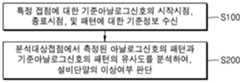
본 발명의 일 실시예에 따르면, 관리자에 의해 입력된 현장제어모듈의 특정 분석대상접점에 대한 기준아날로그신호의 시작시점 및 종료시점, 해당 기준아날로그신호의 패턴을 포함하는 기준정보에 기초하여, 해당 분석대상접점에서 측정된 아날로그신호의 패턴과 기준아날로그신호의 패턴의 유사도에 기초하여 설비단말의 이상여부를 판단할 수 있다.According to one embodiment of the present invention, based on reference information including the start time and end time of a reference analog signal for a specific analysis target contact of a field control module input by an administrator and the pattern of the corresponding reference analog signal, it is possible to determine whether an equipment terminal is abnormal based on the similarity between the pattern of an analog signal measured at the corresponding analysis target contact and the pattern of the reference analog signal.
본 발명의 일 실시예에 따르면, 현장서버가 관리서버로 송신하는 복수의 신호 중 자체적인 규칙성을 가지는 신호를 판별하고, 자체적인 규칙성을 가지는 신호에 대한 정상신호판단기준을 자동적으로 설정하여, 현장서버의 고장여부를 판단할 수 있다.According to one embodiment of the present invention, a signal having its own regularity among a plurality of signals transmitted by a field server to a management server is determined, and a normal signal judgment criterion for the signal having its own regularity is automatically set, thereby determining whether the field server is broken.
본 발명의 일 실시예에 따르면, 관리서버에 의하여 현장서버의 고장이 발생한 것으로 판단되는 경우에, 현장서버로 하여금 현장제어모듈이 현장제어모듈의 복수의 프로그램 중 고장과 관련된 개별 프로그램을 리셋하게끔 하여, 현장서버 혹은 현장제어모듈의 고장을 복구할 수 있다.According to one embodiment of the present invention, when a management server determines that a failure has occurred in a field server, the field server can be caused to reset an individual program related to the failure among a plurality of programs of the field control module, thereby recovering the failure of the field server or field control module.
본 발명의 일 실시예에 따르면, 현장제어모듈의 복수의 프로그램 중 고장과 관련된 개별 프로그램을 리셋한 이후에도 고장이 복구되지 않는 경우에, 관리서버는 현장서버로 하여금 현장제어모듈이 현장제어모듈의 모든 복수의 프로그램을 리셋하게끔 하여, 현장서버 혹은 현장제어모듈의 고장을 복구할 수 있다.According to one embodiment of the present invention, if a failure is not recovered even after resetting an individual program related to a failure among a plurality of programs of a field control module, the management server can cause the field server to reset all of the plurality of programs of the field control module, thereby recovering the failure of the field server or the field control module.
본 발명의 일 실시예에 따르면, 현장제어모듈과 설비단말에 대한 모니터링 및 제어를 위한 스카다프로그램과 현장제어모듈의 고장여부 판단 및 데이터복구를 위한 관리프로그램이 구현하는 인터페이스가 관리자단말에 제공될 수 있다.According to one embodiment of the present invention, an interface implemented by a SCADA program for monitoring and controlling a field control module and an equipment terminal and a management program for determining whether a field control module is in a fault and recovering data can be provided to a manager terminal.
도 1은 본 발명의 일 실시예에 따른 프로세스제어반의 구성요소를 개략적으로 도시한다.
도 2는 본 발명의 일 실시예에 따른 현장제어모듈에서의 접점신호들을 도시한다.
도 3은 본 발명의 일 실시예에 따른 개별 접점신호의 규칙성에 기초하여 프로세스제어반의 이상여부를 판단하는 방법의 단계를 도시한다.
도 4는 본 발명의 일 실시예에 따른 규칙성테이블생성단계에 대한 사항을 도시한다.
도 5는 본 발명의 일 실시예에 따른 규칙성판단단계에 대한 사항을 도시한다.
도 6은 본 발명의 일 실시예에 따른 제1정상허용범위설정단계에 대한 사항을 도시한다.
도 7은 본 발명의 일 실시예에 따른 접점신호 상호간의 관계성에 기초하여 프로세스제어반의 이상여부를 판단하는 방법의 단계를 도시한다.
도 8은 본 발명의 일 실시예에 따른 관계성테이블생성단계에 대한 사항을 도시한다.
도 9는 본 발명의 일 실시예에 따른 관계성테이블의 생성여부의 결정에 대한 사항을 도시한다.
도 10은 본 발명의 일 실시예에 따른 제1대상접점신호그룹 및 제2대상접점신호그룹에 대한 사항을 도시한다.
도 11은 본 발명의 일 실시예에 따른 아날로그신호의 규칙성 및 관계성에 기초하여 프로세스제어반의 이상여부를 판단하는 방법의 단계를 도시한다.
도 12는 본 발명의 일 실시예에 따른 근사AD변환단계에 대한 사항을 도시한다.
도 13은 본 발명의 일 실시예에 따른 아날로그신호의 패턴유사도에 기초하여 프로세스제어반의 이상여부를 판단하는 방법의 단계를 도시한다.
도 14는 본 발명의 일 실시예에 따른 기준정보수신단계 및 제4이상여부판단단계에 대한 사항을 도시한다.
도 15는 본 발명의 일 실시예에 따른 프로세스제어반의 구성요소들을 도시한다.
도 16은 본 발명의 일 실시예에 따른 프로세스제어반이 제공하는 인터페이스를 도시한다.
도 17은 본 발명의 일 실시예에 따른 현장서버가 관리서버로 송신하는 신호를 도시한다.
도 18은 본 발명의 일 실시예에 따른 현장제어모듈의 고장을 판단하고 복구하는 단계들을 도시한다.
도 19는 본 발명의 일 실시예에 따른 컴퓨팅장치의 내부 구성을 개략적으로 도시한다.
FIG. 1 schematically illustrates components of a process control panel according to one embodiment of the present invention.
Figure 2 illustrates contact signals in a field control module according to one embodiment of the present invention.
FIG. 3 illustrates steps of a method for determining whether a process control panel is abnormal based on the regularity of individual contact signals according to one embodiment of the present invention.
Figure 4 illustrates details of a regularity table generation step according to one embodiment of the present invention.
Figure 5 illustrates details of a regularity judgment step according to one embodiment of the present invention.
Figure 6 illustrates details of a first normal tolerance range setting step according to one embodiment of the present invention.
FIG. 7 illustrates steps of a method for determining whether a process control panel is abnormal based on the relationship between contact signals according to one embodiment of the present invention.
Figure 8 illustrates details of a relationship table creation step according to one embodiment of the present invention.
FIG. 9 illustrates matters regarding a decision on whether to create a relationship table according to one embodiment of the present invention.
FIG. 10 illustrates details of a first target contact signal group and a second target contact signal group according to one embodiment of the present invention.
FIG. 11 illustrates steps of a method for determining whether a process control panel is abnormal based on the regularity and relationship of an analog signal according to one embodiment of the present invention.
Figure 12 illustrates details of an approximate AD conversion step according to one embodiment of the present invention.
FIG. 13 illustrates steps of a method for determining whether a process control panel is abnormal based on pattern similarity of an analog signal according to one embodiment of the present invention.
Figure 14 illustrates details of a reference information receiving step and a fourth abnormality determination step according to one embodiment of the present invention.
FIG. 15 illustrates components of a process control panel according to one embodiment of the present invention.
FIG. 16 illustrates an interface provided by a process control panel according to one embodiment of the present invention.
Figure 17 illustrates a signal transmitted by a field server to a management server according to one embodiment of the present invention.
FIG. 18 illustrates steps for determining and recovering a failure of a field control module according to one embodiment of the present invention.
FIG. 19 schematically illustrates the internal configuration of a computing device according to one embodiment of the present invention.
이하에서는, 다양한 실시예들 및/또는 양상들이 이제 도면들을 참조하여 개시된다. 하기 설명에서는 설명을 목적으로, 하나이상의 양상들의 전반적 이해를 돕기 위해 다수의 구체적인 세부사항들이 개시된다. 그러나, 이러한 양상(들)은 이러한 구체적인 세부사항들 없이도 실행될 수 있다는 점 또한 본 발명의 기술 분야에서 통상의 지식을 가진 자에게 인식될 수 있을 것이다. 이후의 기재 및 첨부된 도면들은 하나 이상의 양상들의 특정한 예시적인 양상들을 상세하게 기술한다. 하지만, 이러한 양상들은 예시적인 것이고 다양한 양상들의 원리들에서의 다양한 방법들 중 일부가 이용될 수 있으며, 기술되는 설명들은 그러한 양상들 및 그들의 균등물들을 모두 포함하고자 하는 의도이다.Hereinafter, various embodiments and/or aspects are now disclosed with reference to the drawings. In the following description, for purposes of explanation, numerous specific details are set forth in order to provide a thorough understanding of one or more of the aspects. It will be recognized, however, by one skilled in the art that such aspect(s) may be practiced without these specific details. The following description and the annexed drawings set forth specific exemplary aspects of one or more of the aspects in detail. It should be understood, however, that these aspects are exemplary and that any of the various methods of the principles of the various aspects may be utilized, and the description is intended to encompass all such aspects and their equivalents.
또한, 다양한 양상들 및 특징들이 다수의 디바이스들, 컴포넌트들 및/또는 모듈들 등을 포함할 수 있는 시스템에 의하여 제시될 것이다. 다양한 시스템들이, 추가적인 장치들, 컴포넌트들 및/또는 모듈들 등을 포함할 수 있다는 점 그리고/또는 도면들과 관련하여 논의된 장치들, 컴포넌트들, 모듈들 등 전부를 포함하지 않을 수도 있다는 점 또한 이해되고 인식되어야 한다.Additionally, various aspects and features will be presented by means of systems that may include a number of devices, components, and/or modules, etc. It is also to be understood and appreciated that various systems may include additional devices, components, and/or modules, etc., and/or may not include all of the devices, components, modules, etc. discussed in connection with the drawings.
본 명세서에서 사용되는 "실시예", "예", "양상", "예시" 등은 기술되는 임의의 양상 또는 설계가 다른 양상 또는 설계들보다 양호하다거나, 이점이 있는 것으로 해석되지 않을 수도 있다. 아래에서 사용되는 용어들 '~부', '컴포넌트', '모듈', '시스템', '인터페이스' 등은 일반적으로 컴퓨터 관련 엔티티(computer-related entity)를 의미하며, 예를 들어, 하드웨어, 하드웨어와 소프트웨어의 조합, 소프트웨어를 의미할 수 있다.The terms "embodiment," "example," "aspect," and "example" as used herein are not to be construed as implying that any aspect or design described is better or advantageous over other aspects or designs. The terms "part," "component," "module," "system," and "interface," as used below, generally refer to computer-related entities, and can refer to, for example, hardware, a combination of hardware and software, or software.
또한, "포함한다" 및/또는 "포함하는"이라는 용어는, 해당 특징 및/또는 구성요소가 존재함을 의미하지만, 하나 이상의 다른 특징, 구성요소 및/또는 이들의 그룹의 존재 또는 추가를 배제하지 않는 것으로 이해되어야 한다.Additionally, it should be understood that the terms "comprises" and/or "comprising" imply the presence of the features and/or components, but do not preclude the presence or addition of one or more other features, components and/or groups thereof.
또한, 제1, 제2 등과 같이 서수를 포함하는 용어는 다양한 구성요소들을 설명하는데 사용될 수 있지만, 상기 구성요소들은 상기 용어들에 의해 한정되지는 않는다. 상기 용어들은 하나의 구성요소를 다른 구성요소로부터 구별하는 목적으로만 사용된다. 예를 들어, 본 발명의 권리 범위를 벗어나지 않으면서 제1 구성요소는 제2 구성요소로 명명될 수 있고, 유사하게 제2 구성요소도 제1 구성요소로 명명될 수 있다. 및/또는 이라는 용어는 복수의 관련된 기재된 항목들의 조합 또는 복수의 관련된 기재된 항목들 중의 어느 항목을 포함한다.Also, terms including ordinal numbers such as first, second, etc. may be used to describe various components, but the components are not limited by the terms. The terms are only used to distinguish one component from another. For example, without departing from the scope of the present invention, the first component may be referred to as the second component, and similarly, the second component may also be referred to as the first component. The term and/or includes a combination of a plurality of related described items or any item among a plurality of related described items.
또한, 본 발명의 실시예들에서, 별도로 다르게 정의되지 않는 한, 기술적이거나 과학적인 용어를 포함해서 여기서 사용되는 모든 용어들은 본 발명이 속하는 기술 분야에서 통상의 지식을 가진 자에 의해 일반적으로 이해되는 것과 동일한 의미를 가지고 있다. 일반적으로 사용되는 사전에 정의되어 있는 것과 같은 용어들은 관련 기술의 문맥 상 가지는 의미와 일치하는 의미를 가지는 것으로 해석되어야 하며, 본 발명의 실시예에서 명백하게 정의하지 않는 한, 이상적이거나 과도하게 형식적인 의미로 해석되지 않는다.In addition, in the embodiments of the present invention, unless otherwise defined, all terms used herein, including technical or scientific terms, have the same meaning as commonly understood by a person of ordinary skill in the art to which the present invention belongs. Terms defined in commonly used dictionaries should be interpreted as having a meaning consistent with the meaning they have in the context of the relevant technology, and shall not be interpreted in an ideal or overly formal meaning unless explicitly defined in the embodiments of the present invention.
1. 현장제어모듈에서 측정되는 접점신호에 기반한 프로세스제어반의 고장여부 판단방법1. Method for determining whether a process control panel is faulty based on the contact signal measured by the field control module
본 발명에 대한 상세한 설명에 앞서, 이하에서는 “1. 현장제어모듈에서 측정되는 접점신호에 기반한 프로세스제어반의 고장여부 판단방법”에 대해 상술한다. 구체적으로 “1. 현장제어모듈에서 측정되는 접점신호에 기반한 프로세스제어반의 고장여부 판단방법”은 현장제어모듈에서의 접점신호에 기초하여, 설비단말의 이상여부를 판단하는 방법(알고리즘)을 개시하고 있다.Prior to a detailed description of the present invention, “1. A method for determining whether a process control panel is faulty based on a contact signal measured in a field control module” will be described below. Specifically, “1. A method for determining whether a process control panel is faulty based on a contact signal measured in a field control module” discloses a method (algorithm) for determining whether an equipment terminal is abnormal based on a contact signal in a field control module.
본 발명의 “2. 현장제어모듈의 고장판단 및 고장복구 기능을 제공하는 프로세스제어반의 운영방법”은 해당 알고리즘 중 일부와 실질적으로 동일한 알고리즘을 사용하여, 현장서버가 관리서버 송신하는 신호에 기초하여, 현장서버의 고장여부를 판단할 수 있다.The “2. Operation method of a process control panel providing a failure judgment and failure recovery function of a field control module” of the present invention can determine whether a field server is broken based on a signal transmitted from the field server to the management server by using an algorithm substantially identical to some of the algorithms.
본 발명의 프로세서제어반은 수질계측, 수위조절, 유량 혹은 압력 조절 등을 위한 수치리시설 등에 적용될 수 있다. 즉 아래에서 설명하는 설비단말(3)은 수처리시설에 설치된 계측기와 같이 수질, 수위, 유량, 압력 등과 관련된 복수의 지표를 센싱하는 복합센서에 해당할 수 있다.The processor control panel of the present invention can be applied to water treatment facilities for water quality measurement, water level control, flow rate or pressure control, etc. That is, the equipment terminal (3) described below can correspond to a complex sensor that senses multiple indicators related to water quality, water level, flow rate, pressure, etc., such as a measuring device installed in a water treatment facility.
도 1은 본 발명의 일 실시예에 따른 프로세스제어반의 구성요소를 개략적으로 도시한다.FIG. 1 schematically illustrates components of a process control panel according to one embodiment of the present invention.
도 1에 도시된 바와 같이, 프로세스제어반은 설비단말(3)로부터 설비신호를 송수신하는 복수의 접점을 포함하는 현장제어모듈(1) 및 상기 현장제어모듈(1)로부터 수신한 정보에 기초하여 상기 설비단말(3) 및 상기 현장제어모듈(1)의 모니터링 및 제어를 수행하는 현장서버(2)를 포함할 수 있다.As illustrated in Fig. 1, the process control panel may include a field control module (1) including a plurality of contact points for transmitting and receiving equipment signals from an equipment terminal (3), and a field server (2) for monitoring and controlling the equipment terminal (3) and the field control module (1) based on information received from the field control module (1).
또한 프로세스제어반은 현장서버(2)와 통신을 수행하는 관리서버(4) 및 관리서버(4)로부터 수신한 관리프로그램을 통해 현장에 설치된 장비(설비단말(3) 및 현장제어모듈(1) 등)에 대한 관리를 수행하는 관리자단말(5)을 포함할 수 있다.In addition, the process control panel may include a management server (4) that performs communication with the field server (2) and a management terminal (5) that performs management of equipment installed in the field (such as equipment terminal (3) and field control module (1)) through a management program received from the management server (4).
구체적으로 설비단말(3)은 모터, 펌프, 센서 중 1 이상을 포함하는 계장/계측설비일 수 있고, 설비단말(3)에 의하여 생성된 계측신호, 동작신호 중 1 이상을 포함하는 설비신호는 현장제어모듈(1)로 송신될 수 있다. 현장제어모듈(1)은 복수의 설비단말(3) 각각과 설비신호를 송수신하여, 해당 설비신호를 현장서버(2)로 송수신할 수 있다.Specifically, the equipment terminal (3) may be an instrumentation/measurement equipment including at least one of a motor, a pump, and a sensor, and an equipment signal including at least one of a measurement signal and an operation signal generated by the equipment terminal (3) may be transmitted to the field control module (1). The field control module (1) may transmit and receive equipment signals to and from each of a plurality of equipment terminals (3), and transmit and receive the corresponding equipment signals to and from the field server (2).
본 발명의 일 실시예에서, 설비단말(3)은 수처리시설에서 설치되는 수질센서, 수위센서, 유량센서, 압력센서 등을 포함하는 계측기로서, 수위, 수질, 유량, 압력 등을 센싱하고 해당 정보를 현장제어모듈(1)로 송신할 수 있다.In one embodiment of the present invention, the equipment terminal (3) is a measuring device including a water quality sensor, a water level sensor, a flow rate sensor, a pressure sensor, etc., installed in a water treatment facility, and can sense water level, water quality, flow rate, pressure, etc., and transmit the corresponding information to the field control module (1).
본 발명의 일 실시예에서, 프로세스제어반은 설비단말(3)을 포함하는 형태로 구현될 수 있다.In one embodiment of the present invention, the process control panel can be implemented in a form including an equipment terminal (3).
본 발명의 일 실시예에서, 현장제어모듈(1)은 설비단말(3) 외의 다른 현장제어모듈(1)에서의 설비신호를 송수신할 수 있다. 즉 현장제어모듈(1)은 설비단말(3) 뿐만 아니라 타 프로세스제어반의 현장제어모듈(1)과 통신하면서 타 프로세스제어반에서의 설비신호를 송수신할 수 있다.In one embodiment of the present invention, the field control module (1) can transmit and receive equipment signals from other field control modules (1) other than the equipment terminal (3). That is, the field control module (1) can communicate with not only the equipment terminal (3) but also the field control module (1) of another process control panel, and transmit and receive equipment signals from other process control panels.
본 발명의 일 실시예에서, 현장제어모듈(1)은 PLC, RTU, DCS 중 1 이상을 포함할 수 있다.In one embodiment of the present invention, the field control module (1) may include one or more of a PLC, an RTU, and a DCS.
현장서버(2)는 상기 현장제어모듈(1)로부터 수신한 설비신호에 기초하여, 설비단말(3) 및 현장제어모듈(1)의 모니터링과 제어와 관련된 정보를 저장하면서, 설비단말(3) 및 현장제어모듈(1)의 이상여부 또한 판단할 수 있다.The field server (2) stores information related to monitoring and control of the equipment terminal (3) and the field control module (1) based on the equipment signal received from the field control module (1), and can also determine whether the equipment terminal (3) and the field control module (1) are abnormal.
현장서버(2)는 현장제어모듈(1)과 마찬가지로 현장에 구축된 서버일 수 있다.The field server (2) may be a server built on site, similar to the field control module (1).
구체적으로 상기 현장서버(2)는 1 이상의 프로세서 및 1 이상의 메모리를 포함하는 컴퓨팅장치로서, 관리자로 하여금 설비단말(3) 및 현장제어모듈(1)의 모니터링과 제어와 관련된 기능을 제공하는 관리서버(4)에 해당 현장서버(2)가 수집한 정보(즉 설비단말(3) 및 현장제어모듈(1)과 관련된 정보)를 송신할 수 있다.Specifically, the above-mentioned field server (2) is a computing device including one or more processors and one or more memories, and can transmit information collected by the field server (2) (i.e., information related to the facility terminal (3) and the field control module (1)) to a management server (4) that provides a manager with functions related to monitoring and controlling the facility terminal (3) and the field control module (1).
현장서버(2)로부터 이와 같은 정보들을 수신하고 저장하는 관리서버(4)는 관리자단말(5)과 통신을 수행할 수 있다.The management server (4), which receives and stores such information from the field server (2), can communicate with the management terminal (5).
구체적으로 관리자단말(5)은 관리자가 설비단말(3) 및 현장제어모듈(1)의 모니터링과 제어를 수행하기 위한 인터페이스를 제공하는 SCADA프로그램과 설비단말(3) 및 현장제어모듈(1)의 이상여부를 판단하는 이상감지프로그램을 실행할 수 있다.Specifically, the administrator terminal (5) can execute a SCADA program that provides an interface for the administrator to monitor and control the equipment terminal (3) and the field control module (1) and an abnormality detection program that determines whether there is an abnormality in the equipment terminal (3) and the field control module (1).
본 발명의 일 실시예에서, 설비단말(3) 및 현장제어모듈(1)의 모니터링과 제어, 및 설비신호의 수집과 저장 등에 대한 기능과 설비단말(3) 및 현장제어모듈(1)의 이상여부를 판단하고 알림정보를 제공하는 기능이 관리자단말(5)에서 구현되는 단일의 프로그램에서 통합적으로 구현될 수 있다.In one embodiment of the present invention, functions for monitoring and controlling the equipment terminal (3) and the field control module (1), collecting and storing equipment signals, etc., and functions for determining whether the equipment terminal (3) and the field control module (1) are abnormal and providing notification information can be implemented in an integrated manner in a single program implemented in the administrator terminal (5).
한편 현장제어모듈(1)은 복수의 접점을 포함할 수 있다. 구체적으로 현장제어모듈(1)은 설비단말(3), 현장서버(2), 혹은 다른 현장제어모듈(1)과 송수신하면서, 설비신호의 처리와 전송을 위하여 접점신호가 송수신되는 복수의 접점을 포함할 수 있다.Meanwhile, the field control module (1) may include multiple contact points. Specifically, the field control module (1) may include multiple contact points through which contact signals are transmitted and received for processing and transmitting equipment signals while transmitting and receiving with the equipment terminal (3), the field server (2), or another field control module (1).
프로세스제어반은 현장제어모듈(1)의 복수의 접점에서 측정되는 접점신호에 대한 정보에 기초하여, 상기 설비단말(3)에 대한 이상여부를 판단할 수 있다. 구체적으로 프로세스제어반의 현장제어모듈(1)은 복수의 접점에서 측정되는 접점신호 중 설비단말(3)의 이상여부를 판단할 수 있는 접점신호에 해당하는 대상접점신호그룹에 포함시키고, 대상접점신호그룹에 포함된 접점신호에 대한 정보에 기초하여 자체적으로 설비단말(3)의 이상여부를 판단할 수 있다.The process control panel can determine whether there is an abnormality in the equipment terminal (3) based on information about contact signals measured at multiple contact points of the field control module (1). Specifically, the field control module (1) of the process control panel includes in a target contact signal group a contact signal capable of determining whether there is an abnormality in the equipment terminal (3) among the contact signals measured at multiple contact points, and can determine whether there is an abnormality in the equipment terminal (3) based on information about the contact signals included in the target contact signal group.
바람직하게는 현장제어모듈(1) 혹은 현장서버(2)는 자체적으로 설비단말(3)의 이상여부를 판단하고, 설비단말(3)의 이상여부에 대한 판단결과를 현장서버(2)로 송신할 수 있다. 현장서버(2)는 해당 정보를 관리서버(4)로 전송하고 최종적으로는 설비단말(3)의 이상여부에 대한 판단결과에 대한 정보가 관리자단말(5)을 통해 관리자에게 제공할 수 있다.Preferably, the field control module (1) or the field server (2) can independently determine whether there is a problem with the equipment terminal (3) and transmit the determination result regarding whether there is a problem with the equipment terminal (3) to the field server (2). The field server (2) can transmit the relevant information to the management server (4), and ultimately, information regarding the determination result regarding whether there is a problem with the equipment terminal (3) can be provided to the administrator through the administrator terminal (5).
현장제어모듈(1)의 복수의 접점 중 어느 접점에서는 아날로그신호가 출력될 수 있다. 예를 들어, 상기 현장제어모듈(1)의 복수의 접점 중 어느 하나는 설비단말(3)의 ON/OFF 동작을 결정하는 디지털 접점신호에 대한 접점일 수 있고, 다른 어느 하나는 설비단말(3)에서 측정되는 계측값에 대한 아날로그신호에 대한 접점일 수 있다.An analog signal can be output from any of the multiple contact points of the field control module (1). For example, any of the multiple contact points of the field control module (1) can be a contact point for a digital contact signal that determines the ON/OFF operation of the equipment terminal (3), and any of the other contact points can be a contact point for an analog signal for a measurement value measured at the equipment terminal (3).
본 발명의 일 실시예에서 현장제어모듈(1) 혹은 현장서버(2)는 현장제어모듈(1)의 디지털 접점신호뿐만 아니라 아날로그신호에 대해서도 이상여부를 판단할 수 있다.In one embodiment of the present invention, the field control module (1) or the field server (2) can determine whether there is an abnormality not only in the digital contact signal of the field control module (1) but also in the analog signal.
본 발명의 일 실시예에서, 현장제어모듈(1)의 접점은 PLC접점일 수 있다.In one embodiment of the present invention, the contact of the field control module (1) may be a PLC contact.
도 2는 본 발명의 일 실시예에 따른 현장제어모듈(1)에서의 접점신호들을 도시한다.Figure 2 illustrates contact signals in a field control module (1) according to one embodiment of the present invention.
도 2의 (a)에 도시된 바와 같이, 현장제어모듈(1)은 디지털 혹은 아날로그신호가 송수신되는 복수의 접점을 포함할 수 있고, 도 2의 (b)에 도시된 바와 같이 현장제어모듈(1)의 복수의 접점(A 내지 E접점) 각각에서는 디지털 접점신호 혹은 아날로그신호가 송수신될 수 있다.As shown in (a) of Fig. 2, the field control module (1) may include a plurality of contact points through which digital or analog signals are transmitted and received, and as shown in (b) of Fig. 2, a digital contact signal or an analog signal may be transmitted and received at each of the plurality of contact points (contact points A to E) of the field control module (1).
접점신호는 ON/OFF로 스위칭되는 디지털신호로서, 복수의 펄스를 포함할 수 있다. 본 발명에서는 접점신호가 ON되는 시점에서 OFF되는 시점까지의 시간차를 펄스폭으로 정의하고, 접점신호가 ON되는 시점에서 이후에 해당 접점신호가 다시 ON되는 시점까지의 시간차를 주기로 정의한다.A contact signal is a digital signal that switches ON/OFF and may include multiple pulses. In the present invention, the time difference between the point where the contact signal turns ON and the point where it turns OFF is defined as a pulse width, and the time difference between the point where the contact signal turns ON and the point where the contact signal turns ON again is defined as a period.
예시적으로 A접점에서의 접점신호는 ON/OFF를 반복하면서 3개의 펄스를 포함할 수 있고, 3개의 펄스 각각에 대해서 펄스폭 및 주기가 측정될 수 있다.For example, a contact signal at contact A may include three pulses that repeat ON/OFF, and the pulse width and period may be measured for each of the three pulses.
본 발명의 일 실시예에 따르면, 복수의 접점신호 각각에 대한 규칙성 혹은 다른 접점신호와의 관계성에 기초하여 설비단말(3)의 이상여부를 판단할 수 있다.According to one embodiment of the present invention, it is possible to determine whether the equipment terminal (3) is abnormal based on the regularity of each of a plurality of contact signals or the relationship with other contact signals.
한편 본 발명의 일 실시예에 따르면, 접점신호에 기반한 설비단말(3)의 이상여부를 판단하는 기능과 더불어 아날로그신호에 기반하여 설비단말(3)의 이상여부를 판단하는 기능이 구현될 수 있고, 이에 대한 상세한 설명은 후술하도록 한다.Meanwhile, according to one embodiment of the present invention, in addition to the function of determining whether there is an abnormality in the equipment terminal (3) based on a contact signal, a function of determining whether there is an abnormality in the equipment terminal (3) based on an analog signal can be implemented, and a detailed description thereof will be provided later.
예를 들어, 본 발명의 일 실시예에 따르면 E접점에서 측정된 아날로그신호에 기반하여 설비단말(3)의 이상여부를 판단할 수 있다.For example, according to one embodiment of the present invention, it is possible to determine whether the equipment terminal (3) is abnormal based on an analog signal measured at the E contact.
도 3은 본 발명의 일 실시예에 따른 개별 접점신호의 규칙성에 기초하여 프로세스제어반의 이상여부를 판단하는 방법의 단계를 도시한다.FIG. 3 illustrates steps of a method for determining whether a process control panel is abnormal based on the regularity of individual contact signals according to one embodiment of the present invention.
도 3에 도시된 바와 같이, 현장제어모듈에서 측정되는 접점신호에 기반한 프로세스제어반의 고장여부 판단방법으로서, 상기 프로세스제어반은, 설비단말(3)로부터 설비신호를 송수신하는 복수의 접점을 포함하는 현장제어모듈(1); 및 상기 현장제어모듈(1)로부터 수신한 정보에 기초하여 상기 설비단말(3) 및 상기 현장제어모듈(1)의 모니터링 및 제어를 수행하는 현장서버(2);를 포함하고, 상기 방법은, 상기 현장제어모듈(1)의 복수의 접점 각각에서 ON/OFF로 스위칭되는 복수의 접점신호를 측정하는 접점신호측정단계; 상기 복수의 접점신호 각각에 대하여, 해당 접점신호의 복수의 펄스 각각에 대한 펄스폭과 주기를 기록하여 규칙성테이블을 생성하는 규칙성테이블생성단계; 상기 규칙성테이블에 기록된 접점신호의 펄스폭 및 주기 각각에 대한 표준편차 및 평균에 기초하여, 해당 접점신호가 규칙성을 가지고 있는 지를 판단하는 규칙성판단단계; 상기 규칙성판단단계에서 규칙성이 있다고 판단된 접점신호를 제1대상접점신호그룹에 포함시키고, 상기 제1대상접점신호그룹에 포함된 접점신호의 펄스폭, 및 주기 중 1 이상에 대한 제1정상허용범위를 설정하는 제1정상허용범위설정단계; 및 상기 제1대상접점신호그룹에 속하는 접점신호가 상기 제1정상허용범위를 만족하는 지 여부에 기초하여, 상기 설비단말(3)의 이상여부를 판단하는 제1이상여부판단단계;를 포함할 수 있다.As illustrated in FIG. 3, a method for determining whether a process control panel is faulty based on a contact signal measured by a field control module, wherein the process control panel comprises a field control module (1) including a plurality of contacts for transmitting and receiving equipment signals from a facility terminal (3); and a field server (2) for monitoring and controlling the facility terminal (3) and the field control module (1) based on information received from the field control module (1), wherein the method comprises: a contact signal measuring step for measuring a plurality of contact signals that are switched ON/OFF at each of the plurality of contacts of the field control module (1); a regularity table generating step for generating a regularity table by recording the pulse width and period of each of the plurality of pulses of the corresponding contact signals for each of the plurality of contact signals; a regularity determining step for determining whether the corresponding contact signal has regularity based on the standard deviation and average for each of the pulse width and period of the contact signal recorded in the regularity table; The method may include a first normal tolerance setting step of including a contact signal determined to have regularity in the above regularity determination step in a first target contact signal group and setting a first normal tolerance for at least one of the pulse width and period of the contact signal included in the first target contact signal group; and a first abnormality determination step of determining whether the equipment terminal (3) is abnormal based on whether the contact signal belonging to the first target contact signal group satisfies the first normal tolerance.
또한 개별 접점신호의 규칙성과 접점신호간의 관계성에 기반하여 빌딩자동제어장치 및 시스템의 이상여부를 판단하는 방법으로서, 상기 빌딩자동제어장치 및 시스템은, 설비단말(3)로부터 설비신호를 송수신하는 복수의 접점을 포함하는 현장제어모듈(1); 및 상기 현장제어모듈(1)로부터 수신한 정보에 기초하여 상기 설비단말(3) 및 상기 현장제어모듈(1)의 모니터링 및 제어를 수행하는 현장서버(2);를 포함하고, 상기 방법은, 상기 현장제어모듈(1)의 복수의 접점 각각에서 ON/OFF로 스위칭되는 복수의 접점신호를 측정하는 접점신호측정단계; 상기 복수의 접점신호 각각에 대하여, 해당 접점신호의 복수의 펄스 각각에 대한 펄스폭과 주기를 기록하여 규칙성테이블을 생성하는 규칙성테이블생성단계; 상기 규칙성테이블에 기록된 접점신호의 펄스폭 및 주기 각각에 대한 표준편차 및 평균에 기초하여, 해당 접점신호가 규칙성을 가지고 있는 지를 판단하는 규칙성판단단계; 상기 규칙성판단단계에서 규칙성이 있다고 판단된 접점신호를 제1대상접점신호그룹에 포함시키고, 상기 제1대상접점신호그룹에 포함된 접점신호의 펄스폭, 및 주기 중 1 이상에 대한 제1정상허용범위를 설정하는 제1정상허용범위설정단계; 및 상기 제1대상접점신호그룹에 속하는 접점신호가 상기 제1정상허용범위를 만족하는 지 여부에 기초하여, 상기 설비단말(3)의 이상여부를 판단하는 제1이상여부판단단계;를 포함할 수 있다.Also, as a method for determining whether a building automatic control device and system are abnormal based on the regularity of individual contact signals and the relationship between contact signals, the building automatic control device and system comprises a field control module (1) including a plurality of contacts for transmitting and receiving equipment signals from a facility terminal (3); and a field server (2) for monitoring and controlling the facility terminal (3) and the field control module (1) based on information received from the field control module (1); and the method comprises a contact signal measuring step for measuring a plurality of contact signals that are switched ON/OFF at each of the plurality of contacts of the field control module (1); a regularity table generating step for generating a regularity table by recording the pulse width and period of each of the plurality of pulses of the corresponding contact signals for each of the plurality of contact signals; a regularity judgment step for determining whether the corresponding contact signal has a regularity based on the standard deviation and the average for each of the pulse width and period of the contact signal recorded in the regularity table; The method may include a first normal tolerance setting step of including a contact signal determined to have regularity in the above regularity determination step in a first target contact signal group and setting a first normal tolerance for at least one of the pulse width and period of the contact signal included in the first target contact signal group; and a first abnormality determination step of determining whether the equipment terminal (3) is abnormal based on whether the contact signal belonging to the first target contact signal group satisfies the first normal tolerance.
본 발명의 일 실시예에 따르면, 프로세스제어반은 현장제어모듈(1)의 복수의 접점에서 측정되는 복수의 접점신호 각각에 대하여, 해당 접점신호가 규칙성이 있는 지 여부를 판단할 수 있고, 규칙성이 있다고 판단된 접점신호에 대한 이상여부를 판단할 수 있고, 이하의 S1 내지 S5.1단계는 이를 위해 수행되는 단계일 수 있다.According to one embodiment of the present invention, the process control panel can determine whether each of a plurality of contact signals measured at a plurality of contact points of the field control module (1) has a regularity, and can determine whether a contact signal determined to have a regularity is abnormal. The following steps S1 to S5.1 may be steps performed for this purpose.
S1단계는 접점신호측정단계로서, 현장제어모듈(1)의 복수의 접점 각각에서 ON/OFF로 스위칭되는 복수의 접점신호를 측정 혹은 해당 접점신호를 수신하는 단계일 수 있다. 구체적으로 복수의 접점신호는 ON/OFF로 스위칭되는 디지털신호를 포함할 수 있다. 예를 들어 디지털신호에 해당하는 접점신호는 복수의 펄스를 포함하는 신호일 수 있다.Step S1 is a contact signal measurement step, which may be a step of measuring multiple contact signals that are switched ON/OFF at each of multiple contacts of the field control module (1) or receiving the corresponding contact signals. Specifically, the multiple contact signals may include digital signals that are switched ON/OFF. For example, a contact signal corresponding to a digital signal may be a signal that includes multiple pulses.
본 발명의 일 실시예에서, S1단계는 현장제어모듈(1) 혹은 현장서버(2)에 의하여 수행될 수 있다.In one embodiment of the present invention, step S1 can be performed by a field control module (1) or a field server (2).
S2.1단계는 규칙성테이블생성단계로서, 복수의 접점신호 각각에 대하여 해당 접점신호의 복수의 펄스 각각에 대한 펄스폭과 주기를 측정하여, 해당 접점신호의 복수의 펄스 각각에 대한 펄스폭과 주기에 대한 정보가 포함된 규칙성테이블을 생성하는 단계일 수 있다.Step S2.1 may be a step of generating a regularity table, which may be a step of measuring the pulse width and period of each of multiple pulses of each of multiple contact signals, and generating a regularity table that includes information on the pulse width and period of each of multiple pulses of each of the multiple contact signals.
바람직하게는 규칙성테이블은 디지털신호에 해당하는 복수의 접점신호 각각에 대해 생성될 수 있고, 해당 접점신호의 복수의 펄스 각각에 대한 펄스폭과 주기에 대한 정보를 포함할 수 있다.Preferably, the regularity table can be generated for each of a plurality of contact signals corresponding to the digital signal, and can include information on the pulse width and period for each of a plurality of pulses of the corresponding contact signals.
본 발명의 일 실시예에서, S2.1단계는 현장제어모듈(1) 혹은 현장서버(2)에 의하여 수행될 수 있다.In one embodiment of the present invention, step S2.1 can be performed by a field control module (1) or a field server (2).
S3.1단계는 규칙성판단단계로서, 상기 규칙성테이블에 기록된 접점신호의 펄스폭 및 주기 각각에 대한 표준편차 및 평균에 기초하여, 해당 접점신호가 규칙성을 가지고 있는 지 여부를 판단하는 단계일 수 있다.Step S3.1 is a regularity judgment step, which may be a step for judging whether the contact signal has regularity based on the standard deviation and average for each pulse width and period of the contact signal recorded in the regularity table.
구체적으로 프로세스제어반은 복수의 펄스 각각에 대한 펄스폭에 대한 정보에 기초하여, 펄스폭에 대한 표준편차 및 평균을 산출할 수 있고, 복수의 펄스 각각에 대한 펄스폭이 후술하는 [식 1]을 만족하는 비율에 기초하여 해당 접점신호가 규칙성을 가지고 있는 지를 판단할 수 있다.Specifically, the process control panel can calculate the standard deviation and average of the pulse width based on information about the pulse width of each of the plurality of pulses, and can determine whether the corresponding contact signal has regularity based on the ratio of the pulse width of each of the plurality of pulses satisfying [Formula 1] described below.
유사하게, 프로세스제어반은 복수의 펄스 각각에 대한 주기에 대한 정보에 기초하여, 주기에 대한 표준편차 및 평균을 산출할 수 있고, 복수의 펄스 각각에 대한 주기가 후술하는 [식 2]를 만족하는 비율에 기초하여 해당 접점신호가 규칙성을 가지고 있는 지를 판단할 수 있다.Similarly, the process control panel can calculate the standard deviation and average for the period based on information about the period for each of the plurality of pulses, and can determine whether the corresponding contact signal has a regularity based on the ratio of the period for each of the plurality of pulses satisfying [Formula 2] described below.
바람직하게는 프로세스제어반은 펄스폭과 주기 각각에 대해서 접점신호가 규칙성을 가지고 있는 지를 판단하고, 동시에 만족하는 경우에 해당 접점신호가 규칙성을 가지고 있다고 최종판단할 수 있다.Preferably, the process control panel can determine whether the contact signal has regularity for each of the pulse width and period, and if both are satisfied, it can make a final judgment that the contact signal has regularity.
한편 규칙성이 있는 접점신호란, 해당 접점신호의 복수의 펄스 각각에 대한 펄스폭 및 주기가 비교적 동일한 크기로 출력되는 접점신호를 의미할 수 있다.Meanwhile, a regular contact signal may mean a contact signal in which the pulse width and period for each of the multiple pulses of the contact signal are output with relatively equal sizes.
예를 들어, 해당 접점신호의 복수의 펄스 각각에 대한 펄스폭 혹은 주기가 3초/3초/2.99초/3.01초와 같이 출력되는 경우에 해당 접점신호가 규칙성이 있다고 판단될 수 있고, 반대로 해당 접점신호의 복수의 펄스 각각에 대한 펄스폭 혹은 주기가 3초/2초/3초/5초와 같이 출력되는 경우에 해당 접점신호가 규칙성이 없다고 판단될 수 있다.For example, if the pulse width or period for each of the multiple pulses of the corresponding contact signal is output as 3 seconds/3 seconds/2.99 seconds/3.01 seconds, the corresponding contact signal may be judged to be regular, and conversely, if the pulse width or period for each of the multiple pulses of the corresponding contact signal is output as 3 seconds/2 seconds/3 seconds/5 seconds, the corresponding contact signal may be judged to be irregular.
본 발명의 일 실시예에서, S3.1단계는 현장제어모듈(1) 혹은 현장서버(2)에 의하여 수행될 수 있다.In one embodiment of the present invention, step S3.1 can be performed by a field control module (1) or a field server (2).
S4.1단계는 제1정상허용범위설정단계로서, 상기 규칙성판단단계에서 규칙성이 있다고 판단된 접점신호를 제1대상접점신호그룹에 포함시키고, 제1대상접점신호그룹에 포함된 접점신호의 펄스폭, 및 주기 중 1 이상에 대한 제1정상허용범위를 설정하는 단계일 수 있다.Step S4.1 may be a first normal tolerance setting step, which may be a step of including a contact signal determined to have regularity in the regularity judging step in a first target contact signal group, and setting a first normal tolerance for at least one of the pulse width and period of the contact signal included in the first target contact signal group.
구체적으로 제1정상허용범위는 제1대상접점신호그룹에 포함된 접점신호의 복수의 펄스의 펄스폭 및 주기에 대한 평균 및 표준편차에 기초하여 설정될 수 있고, 설정된 제1정상허용범위는 해당 접점신호가 정상에 해당하는 지 여부를 판단하기 위한 기준범위에 해당할 수 있다. 바람직하게는 제1정상허용범위는 펄스폭, 및 주기 각각에 대해서 설정될 수 있다.Specifically, the first normal tolerance range may be set based on the average and standard deviation of the pulse width and period of a plurality of pulses of the contact signal included in the first target contact signal group, and the set first normal tolerance range may correspond to a reference range for determining whether the corresponding contact signal is normal. Preferably, the first normal tolerance range may be set for each of the pulse width and period.
예를 들어, 어떤 접점신호의 주기에 대한 제1정상허용범위가 2.8초 내지 3.2초로 설정되어 있고, 해당 접점신호의 주기가 3.0초인 경우에 해당 접점신호는 정상상태인 것으로 판단될 수 있고, 반대로 해당 접점신호의 주기가 2.0초인 경우에 해당 접점신호는 이상상태인 것으로 판단될 수 있다.For example, if the first normal allowable range for the cycle of a certain contact signal is set to 2.8 seconds to 3.2 seconds and the cycle of the corresponding contact signal is 3.0 seconds, the corresponding contact signal can be judged to be in a normal state, and conversely, if the cycle of the corresponding contact signal is 2.0 seconds, the corresponding contact signal can be judged to be in an abnormal state.
본 발명의 일 실시예에서, S4.1단계는 현장제어모듈(1) 혹은 현장서버(2)에 의하여 수행될 수 있다.In one embodiment of the present invention, step S4.1 can be performed by a field control module (1) or a field server (2).
S5.1단계는 제1이상여부판단단계로서, 제1대상접점신호그룹에 속하는 접점신호가 해당 접점신호에 대해 설정된 제1정상허용범위를 만족하는 지 여부에 기초하여, 설비단말(3)의 이상여부를 판단하는 단계일 수 있다.Step S5.1 is a first abnormality judgment step, which may be a step for judging whether the equipment terminal (3) is abnormal based on whether a contact signal belonging to the first target contact signal group satisfies the first normal tolerance range set for the corresponding contact signal.
전술한 바와 같이 제1대상접점신호그룹에 속하는 접점신호는 펄스폭 및 주기 각각에 대한 제1정상허용범위가 설정되어 있을 수 있고, 프로세스제어반은 측정된 해당 접점신호의 펄스폭 및 주기가 제1정상허용범위를 만족하는 지 여부에 기초하여, 해당 접점신호가 이상여부를 판단할 수 있다.As described above, the contact signals belonging to the first target contact signal group may have first normal allowable ranges set for pulse width and period, respectively, and the process control panel may determine whether the corresponding contact signal is abnormal based on whether the measured pulse width and period of the corresponding contact signal satisfy the first normal allowable range.
나아가 프로세스제어반은 해당 접점신호의 이상여부에 기초하여, 설비단말(3) 혹은 계장제어모듈의 이상여부를 판단할 수 있다.Furthermore, the process control panel can determine whether there is an abnormality in the equipment terminal (3) or instrumentation control module based on whether there is an abnormality in the corresponding contact signal.
본 발명의 일 실시예에서, S5.1단계는 현장서버(2)에 의하여 수행될 수 있다. 즉 현장서버(2)는 현장제어모듈(1)의 접점에서 측정되는 접점신호의 이상여부를 판단하고, 해당 접점신호가 이상이 있는 것으로 판단되는 경우에 해당 현장제어모듈(1) 혹은 해당 현장제어모듈(1)과 연관된 설비단말(3)의 이상상태에 대한 정보가 관리서버(4) 및 관리자단말(5)을 통해 관리자에게 제공될 수 있다.In one embodiment of the present invention, step S5.1 may be performed by the field server (2). That is, the field server (2) determines whether there is an abnormality in the contact signal measured at the contact point of the field control module (1), and if the contact signal is determined to be abnormal, information on the abnormal state of the field control module (1) or the equipment terminal (3) associated with the field control module (1) may be provided to the administrator through the management server (4) and the administrator terminal (5).
도 4는 본 발명의 일 실시예에 따른 규칙성테이블생성단계에 대한 사항을 도시한다.Figure 4 illustrates details of a regularity table generation step according to one embodiment of the present invention.
도 4의 (a)는 A접점과 B접점 각각에 대한 접점신호를 도시한다. 도시된 바와 같이, A접점에 대한 접점신호는 각각에 대한 펄스폭과 주기를 가지는 복수의 펄스를 포함할 수 있다. 구체적으로 A접점에 대한 접점신호의 첫번째 펄스의 펄스폭은 AP1,주기는 At1일 수 있고, 두번째 펄스의 펄스폭은 AP2,주기는 At2일 수 있고, 세번째 펄스의 펄스폭은 AP3,주기는 At3일 수 있다.Fig. 4(a) illustrates contact signals for each of contact A and contact B. As illustrated, the contact signal for contact A may include a plurality of pulses, each having a pulse width and a period. Specifically, the pulse width of the first pulse of the contact signal for contact A may be AP1 and the period may be At1 , the pulse width of the second pulse may be AP2 and the period may be At2 , and the pulse width of the third pulse may be AP3 and the period may be At3 .
한편, 도 4의 (b)에 도시된 바와 같이 현장제어모듈(1)은 A접점에 대한 접점신호의 복수의 펄스 각각에 대한 펄스폭과 주기에 대한 정보를 기록하여, A접점에 대한 접점신호에 대한 규칙성테이블을 생성할 수 있다.Meanwhile, as shown in (b) of Fig. 4, the field control module (1) can record information on the pulse width and period for each of multiple pulses of the contact signal for contact A, thereby generating a regularity table for the contact signal for contact A.
구체적으로 A접점에 대한 접점신호에 대한 규칙성테이블에는, A접점에 대한 접점신호의 복수의 펄스 각각에 대한 펄스폭(AP1,AP2,AP3)에 대한 정보와, A접점에 대한 접점신호의 복수의 펄스 각각에 대한 주기(At1,At2,At3)에 대한 정보가 기록될 수 있다.Specifically, in the regularity table for the contact signal for contact A, information about the pulse width (AP1, AP2, AP3 ) for each of the multiple pulses of the contact signal for contact A, and information about the period (At1 , At2 , At3 ) for each of the multiple pulses of the contact signal for contact A can be recorded.
전술한 바와 같이 현장제어모듈(1)은 복수의 접점신호 각각에 대해서 규칙성테이블을 생성할 수 있다. B접점에 대한 접점신호에 대해서도 동일하게, B접점에 대한 접점신호의 복수의 펄스 각각에 대한 펄스폭(BP1,BP2,BP3)및 주기(Bt1,Bt2,Bt3)에 대한 정보가 기록되는 규칙성테이블이 생성될 수 있다.As described above, the field control module (1) can generate a regularity table for each of a plurality of contact signals. Similarly, for the contact signal for the B contact, a regularity table can be generated in which information on the pulse width (BP1, BP2, BP3 ) and period (Bt1 , Bt2 , Bt3 ) of each of a plurality of pulses of the contact signal for the B contact are recorded.
한편, 현장제어모듈(1)은 복수의 접점신호 각각에 대한 규칙성테이블에 기초하여, 해당 접점신호가 규칙성을 가지고 있는 지를 판단할 수 있다.Meanwhile, the field control module (1) can determine whether a contact signal has a regularity based on a regularity table for each of a plurality of contact signals.
도 5는 본 발명의 일 실시예에 따른 규칙성판단단계에 대한 사항을 도시한다.Figure 5 illustrates details of a regularity judgment step according to one embodiment of the present invention.
도 5에 도시된 바와 같이, 상기 규칙성판단단계는, 상기 규칙성테이블에 기록된 상기 접점신호의 복수의 펄스 각각에 대하여, 펄스폭 및 주기가 각각 하기의 [식 1] 및 [식 2]을 만족하는 지 여부에 대한 비율에 기초하여 해당 접점신호가 규칙성을 가지고 있는 지를 판단할 수 있다.As illustrated in FIG. 5, the regularity judgment step can determine whether the corresponding contact signal has regularity based on the ratio of whether the pulse width and period of each of the plurality of pulses of the contact signal recorded in the regularity table satisfy [Formula 1] and [Formula 2] below.
[식 1][Formula 1]
(펄스폭-μ1) / σ1 < 기준값(pulse width - μ1 ) / σ1 < reference value
(μ1은 규칙성테이블에 기록된 펄스폭의 평균, σ1은 규칙성테이블에 기록된 펄스폭의 표준편차)(μ1 is the average of the pulse widths recorded in the regularity table, σ1 is the standard deviation of the pulse widths recorded in the regularity table)
[식 2][Formula 2]
(주기-μ2) / σ2 < 기준값(Period-μ2 ) / σ2 < Reference value
(μ2은 규칙성테이블에 기록된 주기의 평균, σ2은 규칙성테이블에 기록된 주기의 표준편차)(μ2 is the mean of the periods recorded in the regularity table, σ2 is the standard deviation of the periods recorded in the regularity table)
현장제어모듈(1)은 규칙성테이블에 기록된 접점신호의 복수의 펄스 각각에 대한 펄스폭이 상술한 [식 1]을 만족하는 지 여부를 판단하고, [식 1]을 만족하는 비율이 기설정된 규칙성판단기준을 상회하는 경우, 해당 접점신호가 규칙성을 가지고 있는 것으로 판단할 수 있다.The field control module (1) determines whether the pulse width of each of the multiple pulses of the contact signal recorded in the regularity table satisfies the above-described [Formula 1], and if the ratio satisfying [Formula 1] exceeds the preset regularity judgment criterion, it can be determined that the corresponding contact signal has regularity.
구체적으로 A접점에 대한 접점신호에 대한 규칙성테이블에 기록된 펄스폭(AP1,AP2,AP3)에 대한 평균(μ1)과 표준편차(σ1)를 산출하고, 각각의 펄스폭(AP1,AP2,AP3)을 [식 1]에 대입하여 만족하는 지 여부를 판단할 수 있다.Specifically, the average (μ1 ) and standard deviation (σ1 ) of the pulse widths (AP1, AP2, AP3 ) recorded in the regularity table for the contact signal for contact A are calculated, and by substituting each pulse width (AP1, AP2, AP3 ) into [Equation 1], it is possible to determine whether it is satisfied.
현장제어모듈(1)은 펄스폭이 [식 1]을 만족하는 비율이 기설정된 규칙성판단기준(예를 들어 80%)을 상회하는 경우에, A접점에 대한 접점신호의 펄스폭이 규칙성을 가지고 있는 것으로 판단할 수 있다.The field control module (1) can determine that the pulse width of the contact signal for contact A has regularity when the ratio of the pulse width satisfying [Formula 1] exceeds the preset regularity judgment criterion (e.g., 80%).
동일하게, 규칙성테이블에 기록된 접점신호의 복수의 펄스 각각에 대한 주기가 상술한 [식 2]를 만족하는 지 여부를 판단하고, [식 2]를 만족하는 비율이 기설정된 규칙성판단기준을 상회하는 경우, 해당 접점신호가 규칙성을 가지고 있는 것으로 판단할 수 있다.Likewise, it is determined whether the period of each of the multiple pulses of the contact signal recorded in the regularity table satisfies the above-described [Formula 2], and if the ratio satisfying [Formula 2] exceeds the preset regularity judgment criterion, it can be determined that the corresponding contact signal has regularity.
구체적으로 A접점에 대한 접점신호에 대한 규칙성테이블에 기록된 주기(At1,At2,At3)에 대한 평균(μ2)과 표준편차(σ2)를 산출하고, 각각의 주기(At1,At2,At3)를 [식 2]에 대입하여 만족하는 지 여부를 판단할 수 있다.Specifically, the average (μ2 ) and standard deviation (σ2 ) for the periods (At1 , At2 , At3 ) recorded in the regularity table for the contact signal for contact A are calculated, and by substituting each period (At1 , At2 , At3 ) into [Equation 2], it is possible to determine whether it is satisfied.
현장제어모듈(1)은 주기가 [식 2]를 만족하는 비율이 기설정된 규칙성판단기준을 상회하는 경우에, A접점에 대한 접점신호의 주기가 규칙성을 가지고 있는 것으로 판단할 수 있다.The field control module (1) can determine that the period of the contact signal for contact A has regularity when the ratio satisfying the period [Formula 2] exceeds the preset regularity judgment criterion.
한편 상기 기준값 및 규칙성판단기준은 관리자에 의해 설정된 상수일 수 있고, 예를 들어 기준값은 1, 규칙성판단기준은 90%로 설정될 수 있다.Meanwhile, the above-mentioned standard value and regularity judgment criterion may be constants set by the administrator, and for example, the standard value may be set to 1 and the regularity judgment criterion may be set to 90%.
본 발명의 일 실시예에서, 펄스폭 및 주기 각각에 대해서 동일한 수치의 기준값 및 규칙성판단기준이 적용될 수 있다. 또는 본 발명의 다른 실시예에서, 펄스폭 및 주기 각각에 대해서 기준값 및 규칙성판단기준이 상이하게 적용될 수 있다.In one embodiment of the present invention, the same numerical reference value and regularity judgment criterion may be applied to each of the pulse width and period. Or, in another embodiment of the present invention, different reference values and regularity judgment criteria may be applied to each of the pulse width and period.
도 5의 (a)는 규칙성이 있는 접점신호의 복수의 펄스 각각에 대한 펄스폭 혹은 주기를 도식화한 것으로, 도시된 바와 같이 표준편차가 작게 해당 접점신호에 대한 펄스폭 혹은 주기가 분포될 수 있다. 또한 표준편차가 작을수록 펄스폭 혹은 주기가 상술한 [식 1] 혹은 [식 2]를 만족하는 비율이 높아질 수 있다.Figure 5 (a) is a diagram illustrating the pulse width or period for each of multiple pulses of a regular contact signal. As illustrated, the pulse width or period for the corresponding contact signal can be distributed with a small standard deviation. In addition, the smaller the standard deviation, the higher the rate at which the pulse width or period satisfies the above-described [Formula 1] or [Formula 2].
달리 말하자면, 접점신호가 규칙성이 있는 경우에, 해당 접점신호의 복수의 펄스 각각에 대한 펄스폭 혹은 주기가 상대적으로 안정되고 일정함을 의미할 수 있다.In other words, when a contact signal has regularity, it can mean that the pulse width or period of each of the multiple pulses of the contact signal is relatively stable and constant.
도 5의 (b)는 규칙성이 없는 접점신호의 복수의 펄스 각각에 대한 펄스폭 혹은 주기를 도식화한 것으로, 도시된 바와 같이 표준편차가 크게 해당 접점신호에 대한 펄스폭 혹은 주기가 분포될 수 있다. 또한 표준편차가 클수록 펄스폭 혹은 주기가 상술한 [식 1] 혹은 [식 2]를 만족하는 비율이 낮아질 수 있다.Figure 5 (b) is a diagram illustrating the pulse width or period for each of multiple pulses of a contact signal without a regularity. As illustrated, the pulse width or period for the corresponding contact signal may be distributed with a large standard deviation. In addition, the larger the standard deviation, the lower the rate at which the pulse width or period satisfies the above-described [Formula 1] or [Formula 2].
달리 말하자면, 접점신호가 규칙성이 없는 경우에, 해당 접점신호의 복수의 펄스 각각에 대한 펄스폭 혹은 주기가 상대적으로 변동이 큼을 의미할 수 있다.In other words, if the contact signal is irregular, it may mean that the pulse width or period of each of the multiple pulses of the contact signal has relatively large fluctuations.
이와 같은 방식으로 프로세스제어반은 현장제어모듈(1)의 복수의 접점 중 규칙성을 가지는 접점신호가 측정되는 접점을 자동적으로 식별할 수 있고, 식별된 해당 접점에서의 접점신호에 기초하여 설비단말(3)의 이상여부를 판단할 수 있다.In this way, the process control panel can automatically identify a contact point among multiple contact points of the field control module (1) at which a contact signal having regularity is measured, and can determine whether there is an abnormality in the equipment terminal (3) based on the contact signal at the identified contact point.
즉, 본 발명의 일 실시예에 따르면 현장제어모듈(1)의 복수의 접점 중 설비단말(3)의 이상여부 판단과 관련된 접점을 관리자가 직접 설정할 필요없이, 규칙성을 가지는 접점신호를 송수신하는 접점이 설비단말(3)의 이상여부 판단과 관련된 접점으로 자동적으로 설정될 수 있다.That is, according to one embodiment of the present invention, without the need for the administrator to directly set a contact point related to determining whether the equipment terminal (3) is abnormal among the multiple contact points of the field control module (1), a contact point that transmits and receives a contact signal having a regularity can be automatically set as a contact point related to determining whether the equipment terminal (3) is abnormal.
도 6은 본 발명의 일 실시예에 따른 제1정상허용범위설정단계에 대한 사항을 도시한다.Figure 6 illustrates details of a first normal tolerance range setting step according to one embodiment of the present invention.
도 6에 도시된 바와 같이, 상기 제1정상허용범위설정단계는, 상기 규칙성테이블에 기록된 상기 접점신호의 복수의 펄스 각각에 대하여, 펄스폭 및 주기 각각에 대한 평균 및 표준편차에 기초하여, 해당 접점신호의 펄스폭 및 주기 각각에 대한 제1정상허용범위를 설정할 수 있다.As illustrated in FIG. 6, the first normal allowable range setting step can set a first normal allowable range for each pulse width and period of the contact signal, based on the average and standard deviation for each pulse width and period of each of the plurality of pulses of the contact signal recorded in the regularity table.
프로세스제어반은 규칙성이 있다고 판단되는 접점신호를 제1대상접점신호그룹에 포함시키고, 해당 접점신호의 펄스폭 및 주기 각각에 대한 제1정상허용범위를 설정할 수 있다. 구체적으로 제1대상접점신호그룹이란 복수의 접접신호 중 설비단말(3)의 이상여부를 판단하기 위한 접점신호의 그룹에 해당할 수 있다.The process control panel can include a contact signal judged to have regularity in a first target contact signal group and set a first normal allowable range for each pulse width and period of the corresponding contact signal. Specifically, the first target contact signal group may correspond to a group of contact signals for judging whether or not the equipment terminal (3) is abnormal among multiple contact signals.
즉, 복수의 접점신호 중 자체적으로 규칙성이 있는 접점신호에 기반하여 설비단말(3)의 이상여부가 판단될 수 있다.That is, whether or not the equipment terminal (3) is abnormal can be determined based on a contact signal that has its own regularity among multiple contact signals.
프로세스제어반은 제1대상접점신호그룹에 포함된 접점신호, 즉 규칙성이 있는 접점신호의 펄스폭 및 주기 각각에 대한 평균 및 표준편차에 기초하여, 펄스폭 및 주기 각각에 대한 제1정상허용범위를 설정할 수 있다.The process control panel can set a first normal allowable range for each pulse width and period based on the average and standard deviation for each pulse width and period of the contact signals included in the first target contact signal group, i.e., the contact signals having regularity.
프로세스제어반은 해당 접점에서 측정된 접점신호의 펄스폭 및 주기가 설정된 제1정상허용범위를 만족하는 경우에, 해당 접점신호가 정상인 것으로 판단할 수 있다.The process control panel can determine that the contact signal is normal if the pulse width and period of the contact signal measured at the contact satisfies the set first normal allowable range.
도 6에 도시된 바와 같이, 본 발명의 일 실시예에서 제1정상허용범위는 μ-6σ에서 μ+6σ까지의 범위로 설정될 수 있다. 구체적으로 본 발명의 일 실시예에서 펄스폭에 대한 제1정상허용범위는 펄스폭의 평균(μ1)과 표준편차(σ1)에 기초하여, μ1-6σ1에서 μ1+6σ1까지의 범위로 설정될 수 있고, 주기에 대한 제1정상허용범위는 주기의 평균(μ2)과 표준편차(σ2)에 기초하여, μ2-6σ2에서 μ2+6σ2까지의 범위로 설정될 수 있다.As illustrated in FIG. 6, in one embodiment of the present invention, the first normal tolerance range may be set to a range from μ-6σ to μ+6σ. Specifically, in one embodiment of the present invention, the first normal tolerance range for the pulse width may be set to a range from μ 1 -
도 7은 본 발명의 일 실시예에 따른 접점신호 상호간의 관계성에 기초하여 프로세스제어반의 이상여부를 판단하는 방법의 단계를 도시한다.FIG. 7 illustrates steps of a method for determining whether a process control panel is abnormal based on the relationship between contact signals according to one embodiment of the present invention.
도 7에 도시된 바와 같이 상기 방법은, 상기 복수의 접점신호 중 임의의 2개 접점신호를 선택한 신호조합 각각에 대하여, 해당 신호조합의 어느 하나의 접점신호가 ON 또는 OFF되는 시점에서 나머지 하나의 접점신호가 ON 또는 OFF되는 시점까지의 시점차이시간을 기록하여 관계성테이블을 생성하는 관계성테이블생성단계; 상기 관계성테이블에 기록된 신호조합 각각에 대하여, 해당 신호조합의 2개 접점신호의 시점차이시간에 대한 표준편차 및 평균에 기초하여, 해당 2개 접점신호 상호간이 관계성을 가지는 지를 판단하는 관계성판단단계; 상기 관계성판단단계에서 관계성이 있다고 판단된 2개의 접점신호를 제2대상접점신호그룹에 포함시키고, 상기 제2대상접점신호그룹의 페어된 2개의 접점신호의 시점차이시간에 대한 제2정상허용범위를 설정하는 제2정상허용범위설정단계; 및 상기 제2대상접점신호그룹에 속하는 2개의 대상접점신호의 시점차이시간이 제2정상허용범위를 만족하는 지 여부에 기초하여, 상기 설비단말(3)의 이상여부를 판단하는 제2이상여부판단단계;를 더 포함할 수 있다.As illustrated in FIG. 7, the method comprises: a relationship table generation step of generating a relationship table by recording, for each signal combination in which two contact signals among the plurality of contact signals are selected, a time difference between the time when one of the contact signals of the corresponding signal combination turns ON or OFF and the time when the other contact signal turns ON or OFF; a relationship judgment step of determining, for each signal combination recorded in the relationship table, whether the two contact signals have a relationship based on the standard deviation and the average of the time difference between the two contact signals of the corresponding signal combination; a second normal tolerance setting step of including the two contact signals determined to have a relationship in the relationship judgment step in a second target contact signal group and setting a second normal tolerance range for the time difference between the two contact signals paired in the second target contact signal group; And it may further include a second abnormality judgment step for judging whether the equipment terminal (3) is abnormal based on whether the time difference between the two target contact signals belonging to the second target contact signal group satisfies the second normal allowable range.
본 발명의 일 실시예에 따르면, 프로세스제어반은 현장제어모듈(1)의 복수의 접점 중 임의의 2개 접짐신호를 선택한 신호조합 각각에 대하여, 해당 신호조합의 2개 접점신호가 서로 관계성이 있는 지 여부를 판단할 수 있고, 관계성이 있다고 판단된 신호조합에 대한 이상여부를 판단할 수 있고, 이하의 S1 내지 S5.2단계는 이를 위해 수행되는 단계일 수 있다.According to one embodiment of the present invention, the process control panel can determine whether two contact signals of each signal combination selected from two arbitrary contact signals among a plurality of contacts of the field control module (1) are related to each other, and can determine whether there is an abnormality with respect to a signal combination determined to be related. The following steps S1 to S5.2 may be steps performed for this purpose.
S1단계는 접점신호측정단계로서, 현장제어모듈(1)의 복수의 접점 각각에서 ON/OFF로 스위칭되는 복수의 접점신호를 측정하는 단계일 수 있다. 구체적으로 복수의 접점신호는 ON/OFF로 스위칭되는 디지털신호를 포함할 수 있다. 예를 들어 디지털신호에 해당하는 접점신호는 복수의 펄스를 포함하는 신호일 수 있다.Step S1 is a contact signal measurement step, which may be a step of measuring multiple contact signals that are switched ON/OFF at each of multiple contacts of the field control module (1). Specifically, the multiple contact signals may include digital signals that are switched ON/OFF. For example, a contact signal corresponding to a digital signal may be a signal that includes multiple pulses.
바람직하게는 도 7의 S1단계는 도 3에서 전술한 S1단계와 동일한 단계에 해당할 수 있다.Preferably, step S1 of Fig. 7 may correspond to the same step as step S1 described above in Fig. 3.
본 발명의 일 실시예에서, S1단계는 현장제어모듈(1) 혹은 현장서버(2)에 의하여 수행될 수 있다.In one embodiment of the present invention, step S1 can be performed by a field control module (1) or a field server (2).
S2.2단계는 관계성테이블생성단계로서, 복수의 접점신호 중 임의의 2개 접점신호를 선택한 신호조합 각각에 대하여, 해당 신호조합의 어느 하나의 접점신호가 ON 또는 OFF되는 시점에서 나머지 하나의 접점신호가 ON 또는 OFF되는 시점까지의 시점차이시간을 측정하여, 해당 신호조합의 2개 접점신호의 시점차이시간에 대한 정보가 포함된 관계성테이블을 생성하는 단계일 수 있다.Step S2.2 is a relationship table generation step, and may be a step of generating a relationship table including information on the time difference between two contact signals of the signal combination by measuring the time difference between the time when one contact signal of the signal combination turns ON or OFF and the time when the other contact signal turns ON or OFF for each signal combination in which two contact signals are selected randomly from among a plurality of contact signals.
바람직하게는 관계성테이블은 디지털신호에 해당하는 복수의 접점신호 중 임의의 2개 접점신호를 선택한 복수의 신호조합 각각에 대해 생성될 수 있고, 해당 신호조합의 2개 접점신호의 시점차이시간에 대한 정보를 포함할 수 있다.Preferably, the relationship table may be generated for each of a plurality of signal combinations in which two contact signals are selected from among a plurality of contact signals corresponding to digital signals, and may include information on the time difference between the two contact signals of the corresponding signal combination.
한편 관계성테이블에는 신호조합의 어느 하나의 접점신호의 ON 또는 OFF되는 시점에서 나머지 하나의 접점신호의 ON 또는 OFF되는 시점까지 복수의 시점차이시간을 포함할 수 있고, 이에 대한 상세한 설명은 후술하도록 한다.Meanwhile, the relationship table may include multiple time difference periods from the point in time when one contact signal of the signal combination turns ON or OFF to the point in time when the remaining contact signal turns ON or OFF, and a detailed description of this will be provided later.
본 발명의 일 실시예에서, S2.2단계는 현장제어모듈(1) 혹은 현장서버(2)에 의하여 수행될 수 있다.In one embodiment of the present invention, step S2.2 can be performed by a field control module (1) or a field server (2).
S3.2단계는 관계성판단단계로서, 관계성테이블에 기록된 신호조합 각각에 대하여, 해당 신호조합의 2개 접점신호의 시점차이시간에 대한 표준편차 및 평균에 기초하여, 해당 신호조합의 2개 접점신호 상호간이 관계성을 가지는 지 여부를 판단하는 단계일 수 있다.Step S3.2 is a relationship judgment step, which may be a step for judging whether two contact signals of each signal combination recorded in the relationship table have a relationship based on the standard deviation and average of the time difference between the two contact signals of the signal combination.
구체적으로 프로세스제어반은 신호조합의 2개 접점신호의 시점차이시간에 대한 정보에 기초하여, 시점차이시간에 대한 표준편차 및 평균을 산출할 수 있고, 복수의 시점차이시간 각각이 후술하는 [식 3]을 만족하는 비율에 기초하여 해당 신호조합의 2개 접점신호가 서로 관계성을 가지고 있는 지를 판단할 수 있다.Specifically, the process control panel can calculate the standard deviation and average of the time difference times based on information about the time difference times of two contact signals of the signal combination, and can determine whether the two contact signals of the signal combination have a relationship with each other based on the ratio of each of the multiple time difference times satisfying [Formula 3] described below.
한편 서로 관계성이 있는 2개 접점신호란, 어느 하나의 접점신호가 ON 또는 OFF시점에서 나머지 하나의 접점신호가 ON 또는 OFF되는 시점의 차이에 대한 시점차이시간이 비교적 동일한 2개의 접점신호를 의미할 수 있다.Meanwhile, two contact signals that are related to each other may mean two contact signals that have relatively equal time differences in the timing between when one contact signal turns ON or OFF and when the other contact signal turns ON or OFF.
예를 들어, 어느 하나의 접점신호가 ON되는 시점에서 나머지 하나의 접점신호가 ON되는 시점의 차이가 3초/3초/2.99초/3.01초와 같은 경우에, 해당 2개의 접점신호가 서로 관계성이 있다고 판단될 수 있고, 반대로 어느 하나의 접점신호가 ON되는 시점에서 나머지 하나의 접점신호가 ON되는 시점의 차이가 3초/2초/3초/5초와 같은 경우에, 해당 2개의 접점신호가 서로 관계성이 없다고 판단될 수 있다.For example, if the difference between the time when one contact signal turns ON and the time when the other contact signal turns ON is 3 seconds/3 seconds/2.99 seconds/3.01 seconds, the two contact signals can be determined to be related to each other, and conversely, if the difference between the time when one contact signal turns ON and the time when the other contact signal turns ON is 3 seconds/2 seconds/3 seconds/5 seconds, the two contact signals can be determined to be unrelated to each other.
또는 어느 하나의 접점신호와 나머지 하나의 접점신호가 각각 개별적인 동작을 가지는 경우에, 해당 2개의 접점신호가 서로 관계성이 없다고 판단될 수 있다.Or, if one contact signal and the other contact signal each have independent operations, it may be determined that the two contact signals are not related to each other.
본 발명의 일 실시예에서, S3.2단계는 현장제어모듈(1) 혹은 현장서버(2)에 의하여 수행될 수 있다.In one embodiment of the present invention, step S3.2 can be performed by a field control module (1) or a field server (2).
S4.2단계는 제2정상허용범위설정단계로서, 상기 관계성판단단계에서 관계성이 있다고 판단된 2개의 접점신호를 제2대상접점신호그룹에 포함시키고, 제2대상접점신호그룹에 포함된 페어된 2개 접점신호의 시점차이시간에 대한 제2정상허용범위를 설정하는 단계일 수 있다.Step S4.2 may be a second normal tolerance setting step, which may be a step of including two contact signals determined to have a relationship in the relationship judgment step into a second target contact signal group, and setting a second normal tolerance for the time difference between the two paired contact signals included in the second target contact signal group.
구체적으로 제2정상허용범위는 제2대상접점신호그룹에 포함된 2개 접점신호의 시점차이시간에 대한 평균 및 표준편차에 기초하여 설정될 수 있고, 설정된 제2정상허용범위는 해당 2개 접점신호가 정상에 해당하는 지 여부를 판단하기 위한 기준범위에 해당할 수 있다.Specifically, the second normal tolerance range can be set based on the average and standard deviation of the time difference between the two contact signals included in the second target contact signal group, and the set second normal tolerance range can correspond to a reference range for determining whether the two contact signals are normal.
예를 들어, 어떤 신호조합의 2개 접점신호의 시점차이시간에 대한 제2정상허용범위가 2.8초 내지 3.2초로 설정되어 있고, 해당 2개 접점신호의 시점차이시간이 3.0초인 경우에 해당 2개 접점신호는 정상상태인 것으로 판단될 수 있고, 반대로 해당 접점신호의 시점차이시간이 2.0초인 경우에 해당 2개 접점신호는 이상상태인 것으로 판단될 수 있다.For example, if the second normal allowable range for the time difference between two contact signals of a certain signal combination is set to 2.8 seconds to 3.2 seconds and the time difference between the two contact signals is 3.0 seconds, the two contact signals can be judged to be in a normal state, and conversely, if the time difference between the two contact signals is 2.0 seconds, the two contact signals can be judged to be in an abnormal state.
본 발명의 일 실시예에서, S4.2단계는 현장제어모듈(1) 혹은 현장서버(2)에 의하여 수행될 수 있다.In one embodiment of the present invention, step S4.2 can be performed by a field control module (1) or a field server (2).
S5.2단계는 제2이상여부판단단계로서, 제2대상접점신호그룹에 속하는 2개의 접점신호가 해당 2개 접점신호에 대해 설정된 제2정상허용범위를 만족하는 지 여부에 기초하여, 설비단말(3)의 이상여부를 판단하는 단계일 수 있다.Step S5.2 is a second abnormality judgment step, which may be a step for judging whether the equipment terminal (3) is abnormal based on whether two contact signals belonging to the second target contact signal group satisfy the second normal tolerance range set for the two contact signals.
전술한 바와 같이 제2대상접점신호그룹에 속하는 2개 접점신호의 시점차이시간에 대한 제2정상허용범위가 설정되어 있을 수 있고, 프로세스제어반은 측정된 해당 2개 접점신호의 시점차이시간이 제2정상허용범위를 만족하는 지 여부에 기초하여, 해당 2개 접점신호의 이상여부를 판단할 수 있다.As described above, a second normal allowable range may be set for the time difference between two contact signals belonging to the second target contact signal group, and the process control panel may determine whether the two contact signals are abnormal based on whether the measured time difference between the two contact signals satisfies the second normal allowable range.
나아가 프로세스제어반은 해당 2개 접점신호의 이상여부에 기초하여, 설비단말(3) 혹은 계장제어모듈의 이상여부를 판단할 수 있다.Furthermore, the process control panel can determine whether there is an abnormality in the equipment terminal (3) or instrumentation control module based on whether there is an abnormality in the two contact signals.
본 발명의 일 실시예에서, S5.2단계는 현장서버(2)에 의하여 수행될 수 있다. 즉 현장서버(2)는 현장제어모듈(1)의 접점 중 서로 관계성이 있는 2개 접점에서 각각 측정되는 접점신호의 이상여부를 판단하고, 해당 2개 접점신호가 이상이 있는 것으로 판단되는 경우에 해당 현장제어모듈(1) 혹은 해당 현장제어모듈(1)과 연관된 설비단말(3)의 이상상태에 대한 정보가 관리서버(4) 및 관리자단말(5)을 통해 관리자에게 제공될 수 있다.In one embodiment of the present invention, step S5.2 may be performed by the field server (2). That is, the field server (2) determines whether there is an abnormality in the contact signals measured at two contact points that are related to each other among the contact points of the field control module (1), and if it is determined that there is an abnormality in the two contact points, information on the abnormal state of the field control module (1) or the equipment terminal (3) related to the field control module (1) may be provided to the administrator through the management server (4) and the administrator terminal (5).
도 8은 본 발명의 일 실시예에 따른 관계성테이블생성단계에 대한 사항을 도시한다.Figure 8 illustrates details of a relationship table creation step according to one embodiment of the present invention.
도 8에 도시된 바와 같이, 상기 관계성테이블에서의 복수의 접점신호 중 임의로 선택된 2개의 접점신호의 신호조합 각각에 대한 시점차이시간은, 해당 신호조합의 어느 하나의 접점신호가 ON되는 시점에서 나머지 하나의 접점신호가 ON되는 시점까지의 제1시점차이시간; 해당 신호조합의 어느 하나의 접점신호가 ON되는 시점에서 나머지 하나의 접점신호가 OFF되는 시점까지의 제2시점차이시간; 해당 신호조합의 어느 하나의 접점신호가 OFF되는 시점에서 나머지 하나의 접점신호가 ON되는 시점까지의 제3시점차이시간; 및 해당 신호조합의 어느 하나의 접점신호가 OFF되는 시점에서 나머지 하나의 접점신호가 OFF되는 시점까지의 제4시점차이시간;에 대한 정보를 포함할 수 있다.As illustrated in FIG. 8, the time difference time for each signal combination of two contact signals randomly selected from among a plurality of contact signals in the relationship table may include information about a first time difference time from the time when one contact signal of the signal combination turns ON to the time when the other contact signal turns ON; a second time difference time from the time when one contact signal of the signal combination turns ON to the time when the other contact signal turns OFF; a third time difference time from the time when one contact signal of the signal combination turns OFF to the time when the other contact signal turns ON; and a fourth time difference time from the time when one contact signal of the signal combination turns OFF to the time when the other contact signal turns OFF.
도 8의 (a)는 A접점과 B접점 각각에 대한 접점신호를 도시한다. 도시된 바와 같이, A접점 및 B접점에 대한 2개 접점신호에 대한 제1시점차이시간은 A접점에 대한 접점신호가 ON되는 시점에서 B접점에 대한 접점신호가 ON되는 시점까지의 시간차에 해당할 수 있고, 각각 AB1,AB2,AB3일 수 있다.Fig. 8 (a) illustrates contact signals for each of contact A and contact B. As illustrated, the first time difference between the two contact signals for contact A and contact B may correspond to the time difference between when the contact signal for contact A turns ON and when the contact signal for contact B turns ON, and may be AB1 , AB2 , and AB3 , respectively.
또한 A접점 및 B접점에 대한 2개 접점신호에 대한 제2시점차이시간은 A접점에 대한 접점신호가 ON되는 시점에서 B접점에 대한 접점신호가 OFF되는 시점까지의 시간차에 해당할 수 있고, 각각 Ab1,Ab2,Ab3일 수 있다.In addition, the second point-in-time difference time for the two contact signals for contact A and contact B may correspond to the time difference from the point in time when the contact signal for contact A turns ON to the point in time when the contact signal for contact B turns OFF, and may be Ab1 , Ab2 , and Ab3 , respectively.
또한 A접점 및 B접점에 대한 2개 접점신호에 대한 제3시점차이시간은 A접점에 대한 접점신호가 OFF되는 시점에서 B접점에 대한 접점신호가 ON되는 시점까지의 시간차에 해당할 수 있고, 각각 aB1,aB2,aB3일 수 있다.In addition, the third time difference between the two contact signals for contacts A and B may correspond to the time difference between when the contact signal for contact A turns OFF and when the contact signal for contact B turns ON, and may be aB1 , aB2 , and aB3 , respectively.
또한 A접점 및 B접점에 대한 2개 접점신호에 대한 제4시점차이시간은 A접점에 대한 접점신호가 OFF되는 시점에서 B접점에 대한 접점신호가 OFF되는 시점까지의 시간차에 해당할 수 있고, 각각 ab1,ab2,ab3일 수 있다.In addition, the fourth time difference between the two contact signals for contacts A and B may correspond to the time difference between when the contact signal for contact A turns OFF and when the contact signal for contact B turns OFF, and may be ab1 , ab2 , and ab3 , respectively.
한편, 도 8의 (b)에 도시된 바와 같이 현장제어모듈(1)은 A접점에 대한 접점신호와 B접점에 대한 접점신호에 대한 시점차이시간에 대한 정보를 기록하여, A접점에 대한 접점신호와 B접점에 대한 접점신호 상호간에 대한 관계성테이블을 생성할 수 있다.Meanwhile, as shown in (b) of Fig. 8, the field control module (1) records information on the time difference between the contact signal for contact A and the contact signal for contact B, thereby generating a relationship table between the contact signal for contact A and the contact signal for contact B.
바람직하게는 A접점에 대한 접점신호와 B접점에 대한 접점신호 상호간에 대한 관계성테이블에는 제1시점차이시간(AB1,AB2,AB3),제2시점차이시간(Ab1,Ab2,Ab3),제3시점차이시간(aB1,aB2,aB3),제4시점차이시간(ab1,ab2,ab3)에 대한 정보를 포함할 수 있다.Preferably, the relationship table between the contact signals for contact A and the contact signals for contact B may include information about the first time difference time (AB1 , AB2 , AB3 ), the second time difference time (Ab1 , Ab2 , Ab3 ), the third time difference time (aB1 , aB2 , aB3 ), and the fourth time difference time (ab1 , ab2 , ab3 ).
한편, 현장제어모듈(1)은 복수의 접점신호 중 임의로 2개의 접점신호를 선택한 신호조합 각각에 대한 관계성테이블에 기초하여, 해당 신호조합의 2개의 접점신호가 서로 관계성을 가지고 있는 지를 판단할 수 있다.Meanwhile, the field control module (1) can determine whether two contact signals of a signal combination have a relationship with each other based on a relationship table for each signal combination in which two contact signals are randomly selected from among multiple contact signals.
도 9는 본 발명의 일 실시예에 따른 관계성테이블의 생성여부의 결정에 대한 사항을 도시한다.FIG. 9 illustrates matters regarding a decision on whether to create a relationship table according to one embodiment of the present invention.
도 9에 도시된 바와 같이, 상기 관계성테이블생성단계는, 상기 복수의 접점신호 중 임의의 2개 접점신호를 선택한 신호조합 각각에 대하여, 어느 하나의 접점신호가 ON 또는 OFF로 동작한 이후에 상기 어느 하나의 접점신호가 ON 또는 OFF 중 동일한 동작을 반복하기 이전에, 나머지 하나의 접점신호가 ON 또는 OFF로 동작하고, 이후에 상기 어느 하나의 접점신호가 ON 또는 OFF 중 동일한 동작을 반복하는 경우에, 상기 해당 신호조합의 어느 하나의 접점신호와 나머지 하나의 접점신호의 동작이 1:1로 짝지어지는 경우로 판단하여, 상기 해당 신호조합의 어느 하나의 접점신호 및 나머지 하나의 접점신호에 대한 관계성테이블을 생성할 수 있다.As illustrated in FIG. 9, in the relationship table generation step, for each signal combination in which any two contact signals among the plurality of contact signals are selected, if one contact signal operates ON or OFF, and before the one contact signal repeats the same operation of being ON or OFF, the other contact signal operates ON or OFF, and thereafter the one contact signal repeats the same operation of being ON or OFF, it is determined that the operations of the one contact signal of the corresponding signal combination and the one contact signal of the other contact signal are paired 1:1, and a relationship table can be generated for the one contact signal and the one contact signal of the corresponding signal combination.
전술한 바와 같이, 복수의 접점신호 중 임의의 2개 접점신호를 선택한 복수의 신호조합 중, 동작이 서로 짝지어지는 신호조합에 대해서만 관계성테이블을 생성할 수 있다.As described above, among multiple signal combinations in which two random contact signals are selected from multiple contact signals, a relationship table can be created only for signal combinations in which operations are paired with each other.
구체적으로 도 9의 (a)에 도시된 바와 같이, A접점에 대한 접점신호가 ON된 이후에, A접점에 대한 접점신호가 다시 ON되기 이전에, B접점에 대한 접점신호가 ON되고, 이후에 A접점에 대한 접점신호가 ON되는 동작을 반복하여, (A접점 ON -> B접점 ON) -> (A접점 ON -> B접점 ON) -> (A접점 ON -> B접점 ON)와 같이 동작이 서로 1:1로 짝지어지는 경우에, A접점에 대한 접점신호와 B접점에 대한 접점신호에 대한 관계성테이블을 생성할 수 있다.Specifically, as illustrated in (a) of FIG. 9, when the contact signal for contact A is turned ON, and before the contact signal for contact A is turned ON again, the contact signal for contact B is turned ON, and then the contact signal for contact A is turned ON, and when the operations are paired 1:1, such as (contact A ON -> contact B ON) -> (contact A ON -> contact B ON) -> (contact A ON -> contact B ON), a relationship table for the contact signal for contact A and the contact signal for contact B can be created.
반대로 도 9의 (b)에 도시된 바와 같이, A접점에 대한 접점신호가 ON된 이후에, A접점에 대한 접점신호가 다시 ON되기 이전에, C접점에 대한 접점신호가 ON되고, 이후에 A접점에 대한 접점신호가 ON되는 동작을 반복하지 않는 경우, 예를 들어 A접점 ON -> C접점 ON -> C접점 ON -> A접점 ON -> C접점 ON -> A접점 ON -> C접점 ON-> C접점 ON와 같이 동작이 서로 1:1로 짝지어지지 않는 경우에, A접점에 대한 접점신호와 C접점에 대한 접점신호에 대한 관계성테이블을 생성하지 않을 수 있다.Conversely, as illustrated in (b) of FIG. 9, if the operation of turning ON the contact signal for contact A, then turning ON the contact signal for contact C before turning ON the contact signal for contact A again, and then turning ON the contact signal for contact A is not repeated, for example, if the operations are not paired 1:1, such as contact A ON -> contact C ON -> contact C ON -> contact A ON -> contact C ON -> contact A ON -> contact C ON-> contact C ON, then a relationship table for the contact signal for contact A and the contact signal for contact C may not be generated.
이와 같이, 동작이 서로 1:1로 짝지어지지 않는 2개 접점신호는 서로 관계성이 없는 접점신호로 판단될 수 있다.In this way, two contact signals whose movements are not paired 1:1 can be judged as contact signals that have no relationship with each other.
본 발명에서는 복수의 접접신호 중 임의로 2개 접점신호를 선택한 모든 신호조합 각각에 대해서 관계성테이블을 생성하지 않고, 해당 신호조합의 2개 접점신호의 동작이 서로 짝지어지는 여부를 먼저 판단하고, 짝지어지는 경우에만 해당 신호조합의 2개 접점신호에 대한 관계성테이블을 생성할 수 있다.In the present invention, instead of generating a relationship table for each signal combination in which two contact signals are randomly selected from among a plurality of contact signals, it is first determined whether the operations of two contact signals of the corresponding signal combination are paired with each other, and only if they are paired can a relationship table be generated for two contact signals of the corresponding signal combination.
결과적으로 본 발명의 일 실시예에 따르면, 관계성테이블을 생성하는 데 소요되는 연산부하량을 대폭 경감할 수 있다.As a result, according to one embodiment of the present invention, the computational load required to create a relationship table can be significantly reduced.
한편 상기 관계성판단단계는, 상기 관계성테이블에 기록된 신호조합의 어느 하나의 접점신호와 나머지 하나의 접점신호 상호간의 시점차이시간이 하기의 [식 3]을 만족하는 지 여부에 기초하여 상기 어느 하나의 접점신호와 나머지 하나의 접점신호 상호간이 관계성을 가지고 있는 지를 판단할 수 있다.Meanwhile, the above relationship judgment step can determine whether one of the contact signals and the remaining contact signal have a relationship based on whether the time difference between one of the contact signals and the remaining contact signal among the signal combinations recorded in the relationship table satisfies [Formula 3] below.
[식 3][Formula 3]
(시점차이시간-μ3) / σ3 < 기준값(Time difference - μ3 ) / σ3 < reference value
(μ3은 관계성테이블에 기록된 시점차이시간의 평균, σ3은 관계성테이블에 기록된 시점차이시간의 표준편차)(μ3 is the average of the time difference times recorded in the relationship table, σ3 is the standard deviation of the time difference times recorded in the relationship table)
현장제어모듈(1)은 관계성테이블에 기록된 신호조합의 2개 접점신호에 대한 복수의 시점차이시간 각각이 상술한 [식 3]을 만족하는 지 여부를 판단하고, [식 3]을 만족하는 비율이 기설정된 관계성판단기준을 상회하는 경우, 해당 2개의 접점신호가 서로 관계성을 가지고 있는 것으로 판단할 수 있다.The field control module (1) determines whether each of multiple time difference times for two contact signals of a signal combination recorded in a relationship table satisfies the above-described [Formula 3], and if the ratio satisfying [Formula 3] exceeds a preset relationship judgment standard, it can be determined that the two contact signals have a relationship with each other.
구체적으로 A접점과 B접점에 대한 접점신호 상호간에 대한 관계성테이블에 기록된 제1시점차이시간(AB1,AB2,AB3)에 대한 평균(μ3)과 표준편차(σ3)를 산출하고, 각각의 제1시점차이시간(AB1,AB2,AB3)을 [식 3]에 대입하여 만족하는 지 여부를 판단할 수 있다.Specifically, the average (μ3 ) and standard deviation (σ3 ) of the first time difference times (AB1 , AB2 , AB3 ) recorded in the relationship table between the contact signals for contacts A and B are calculated, and by substituting each of the first time difference times (AB1 , AB2 , AB3 ) into [Equation 3], it is possible to determine whether it is satisfied.
현장제어모듈(1)은 제1시점차이시간이 [식 3]을 만족하는 비율이 기설정된 관계성판단기준(예를 들어 80%)을 상회하는 경우에, A접점과 B접점에 대한 2개 접점신호 상호간이 관계성을 가지고 있는 것으로 판단할 수 있다.The field control module (1) can determine that two contact signals for contact A and contact B have a relationship if the ratio of the first point-in-time difference time satisfying [Formula 3] exceeds the preset relationship judgment standard (e.g., 80%).
동일하게, 현장제어모듈(1)은 제2시점차이시간(Ab1,Ab2,Ab3),제3시점차이시간(aB1,aB2,aB3),제4시점차이시간(ab1,ab2,ab3)각각에 대해서도, 동일한 판단을 수행할 수 있다.Likewise, the field control module (1) can perform the same judgment for each of the second time difference time (Ab1 , Ab2 , Ab3 ), the third time difference time (aB1 , aB2 , aB3 ), and the fourth time difference time (ab1 , ab2 , ab3 ).
한편 상기 기준값 및 관계성판단기준은 관리자에 의해 설정된 상수일 수 있고, 예를 들어 기준값은 1, 관계성판단기준은 90%로 설정될 수 있다.Meanwhile, the above-mentioned reference value and relationship judgment criterion may be constants set by the administrator, and for example, the reference value may be set to 1 and the relationship judgment criterion may be set to 90%.
본 발명의 일 실시예에서, 제1시점차이시간, 제2시점차이시간, 제3시점차이시간, 제4시점차이시간 각각에 대해서 동일한 수치의 기준값 및 규칙성판단기준이 적용될 수 있다. 또는 본 발명의 다른 실시예에서, 제1시점차이시간, 제2시점차이시간, 제3시점차이시간, 제4시점차이시간 각각에 대해서 기준값 및 관계성판단기준이 상이하게 적용될 수 있다.In one embodiment of the present invention, the same reference value and regularity judgment criterion may be applied to each of the first time difference time, the second time difference time, the third time difference time, and the fourth time difference time. Or, in another embodiment of the present invention, different reference values and relationship judgment criteria may be applied to each of the first time difference time, the second time difference time, the third time difference time, and the fourth time difference time.
바람직하게는 2개 접점신호의 관계성을 판단하기 위한 기준값 및 관계성판단기준은 각각, 도 5에서 개별 접점신호의 규칙성을 판단하기 위한 기준값 및 규칙성판단기준과 서로 동일하게 설정될 수 있다.Preferably, the reference value and the relationship judgment criterion for judging the relationship between two contact signals can be set to be identical to the reference value and the regularity judgment criterion for judging the regularity of individual contact signals in Fig. 5, respectively.
서로 관계성이 있는 2개 접점신호의 시점차이시간은 도 5의 (a)와 같이 도시화될 수 있다. 구체적으로 표준편차가 작을수록 시점차이시간이 상술한 [식 3] 을 만족하는 비율이 높아질 수 있다.The time difference between two contact signals that are related to each other can be graphically depicted as in (a) of Fig. 5. Specifically, the smaller the standard deviation, the higher the rate at which the time difference satisfies the above-described [Equation 3].
달리 말하자면, 2개 접점신호가 서로 관계성이 있는 경우에, 해당 2개 접점신호의 시점차이시간이 상대적으로 일정함을 의미할 수 있다.In other words, when two contact signals are related to each other, it can mean that the time difference between the two contact signals is relatively constant.
서로 관계성이 없는 2개 접점신호의 시점차이시간은 도 5의 (b)와 같이 도시화될 수 있다. 구체적으로 표준편차가 클수록 시점차이시간이 상술한 [식 3] 을 만족하는 비율이 낮아질 수 있다.The time difference between two contact signals that are not related to each other can be visualized as in (b) of Fig. 5. Specifically, the larger the standard deviation, the lower the rate at which the time difference satisfies the above-described [Equation 3].
달리 말하자면, 2개 접점신호가 서로 관계성이 있는 경우에, 해당 2개의 접점신호의 시점차이시간이 상대적으로 변동이 큼을 의미할 수 있다.In other words, when two contact signals are related to each other, it can mean that the time difference between the two contact signals fluctuates relatively greatly.
이와 같은 방식으로 프로세스제어반은 현장제어모듈(1)의 복수의 접점 중 임의로 2개 접점신호를 선택한 신호조합 중 서로 관계성이 있는 신호조합의 2개 접점신호를 자동적으로 식별할 수 있고, 식별된 해당 신호조합의 2개 접점신호에 기초하여 설비단말(3)의 이상여부를 판단할 수 있다.In this way, the process control panel can automatically identify two contact signals of a signal combination that are related to each other among the signal combinations in which two contact signals are randomly selected from among the multiple contacts of the field control module (1), and can determine whether the equipment terminal (3) is abnormal based on the two contact signals of the identified signal combination.
즉, 본 발명의 일 실시예에 따르면 현장제어모듈(1)의 복수의 접점 중 설비단말(3)의 이상여부 판단과 관련된 접점을 관리자가 직접 설정할 필요없이, 서로 관계성을 가지는 접점신호를 송수신하는 2개의 접점이 설비단말(3)의 이상여부 판단과 관련된 접점으로 자동적으로 설정될 수 있다.That is, according to one embodiment of the present invention, without the need for the administrator to directly set a contact point related to determining whether the equipment terminal (3) is abnormal among the multiple contact points of the field control module (1), two contact points that transmit and receive contact signals that have a relationship with each other can be automatically set as contact points related to determining whether the equipment terminal (3) is abnormal.
한편, 상기 제2정상허용범위설정단계는, 상기 관계성테이블에 기록된 신호조합의 어느 하나의 접점신호와 나머지 하나의 접점신호 상호간의 시점차이시간에 대한 평균 및 표준편차에 기초하여, 해당 신호조합의 어느 하나의 접점신호와 나머지 하나의 접점신호 상호간의 시점차이시간에 대한 제2정상허용범위를 설정할 수 있다.Meanwhile, the second normal tolerance range setting step can set the second normal tolerance range for the time difference between one contact signal of the signal combination and the other contact signal based on the average and standard deviation of the time difference between one contact signal of the signal combination and the other contact signal recorded in the relationship table.
프로세스제어반은 서로 관계성이 있다고 판단되는 접점신호를 제2대상접점신호그룹에 포함시키고, 해당 2개 접점신호의 시점차이시간에 대한 제2정상허용범위를 설정할 수 있다. 구체적으로 제2대상접점신호그룹이란 복수의 접접신호 중 설비단말(3)의 이상여부를 판단하기 위한 페어된 2개 접점신호의 그룹에 해당할 수 있다.The process control panel can include contact signals that are judged to be related to each other in a second target contact signal group, and set a second normal allowable range for the time difference between the two contact signals. Specifically, the second target contact signal group can correspond to a group of two paired contact signals for judging whether the equipment terminal (3) is abnormal among multiple contact signals.
즉, 복수의 접점신호 중 임의로 2개 접점신호를 선택한 신호조합 중 서로 관계성이 있는 신호조합의 2개 접점신호에 기반하여 설비단말(3)의 이상여부가 판단될 수 있다.That is, whether or not the equipment terminal (3) is abnormal can be determined based on two contact signals of a signal combination that is related to each other among a signal combination in which two contact signals are randomly selected from among multiple contact signals.
프로세스제어반은 제2대상접점신호그룹에 포함된 페어된 2개 접점신호, 즉 서로 관계성이 있는 페어된 2개 접점신호의 시점차이시간에 대한 평균 및 표준편차에 기초하여, 시점차이시간에 대한 제2정상허용범위를 설정할 수 있다.The process control panel can set a second normal allowable range for the point-in-time difference time based on the average and standard deviation of the point-in-time difference time of two paired contact signals included in the second target contact signal group, i.e., two paired contact signals that are related to each other.
프로세스제어반은 해당 2개 접점에서 측정된 2개 접점신호 상호간의 시점차이시간이 설정된 제2정상허용범위를 만족하는 경우에, 해당 2개의 접점신호가 정상인 것으로 판단할 수 있다.The process control panel can determine that the two contact signals are normal if the time difference between the two contact signals measured at the two contact points satisfies the second normal allowable range.
도 6에 도시된 바와 같이 , 본 발명의 일 실시예에서 제2정상허용범위는 μ-6σ에서 μ+6σ까지의 범위로 설정될 수 있다. 구체적으로 본 발명의 일 실시예에서 서로 관계성이 있는 2개 접점신호의 시점차이시간에 대한 제2정상허용범위는 2개 접점신호의 시점차이시간의 평균(μ3)과 표준편차(σ3)에 기초하여, μ3-6σ3에서 μ3+6σ3까지의 범위로 설정될 수 있다.As illustrated in FIG. 6, in one embodiment of the present invention, the second normal tolerance range may be set to a range from μ-6σ to μ+6σ. Specifically, in one embodiment of the present invention, the second normal tolerance range for the time difference between two contact signals having a relationship with each other may be set to a range fromμ3-6σ3 toμ3 +6σ3 based on the average (μ3 ) and standard deviation (σ3 ) of the time difference between thetwo contact signals.
도 10은 본 발명의 일 실시예에 따른 제1대상접점신호그룹 및 제2대상접점신호그룹에 대한 사항을 도시한다.FIG. 10 illustrates details of a first target contact signal group and a second target contact signal group according to one embodiment of the present invention.
도 10에 도시된 바와 같이 현장제어모듈(1)의 접점에서 측정하는 복수의 접점신호 중, 자체적으로 규칙적인 아웃풋을 출력하여 규칙성이 있거나, 다른 접점신호의 동작에 따라 규칙된 아웃풋을 출력하여 다른 접점신호와의 관계성이 있는 접점신호를 대상접점신호그룹에 포함시킬 수 있다.Among the multiple contact signals measured at the contact points of the field control module (1) as illustrated in Fig. 10, contact signals that have regularity by outputting regular outputs on their own or have a relationship with other contact signals by outputting regular outputs according to the operation of other contact signals can be included in the target contact signal group.
전술한 바와 같이 현장제어모듈(1)은 접점신호가 송수신되는 복수의 접점을 포함할 수 있고, 본 발명의 일 실시예에 따르면 현장제어모듈(1)의 복수의 접점신호 중 자체적인 규칙성을 가지는 접점신호, 혹은 다른 접점신호와의 관계성을 가지는 접점신호를 제1대상접점신호그룹 혹은 제2대상접점신호그룹에 포함시킴으로써, 설비단말(3)의 이상여부를 판단하기 위한 접점신호를 자동적으로 결정할 수 있다.As described above, the field control module (1) may include a plurality of contact points through which contact signals are transmitted and received, and according to one embodiment of the present invention, by including a contact signal having its own regularity or a contact signal having a relationship with another contact signal among the plurality of contact signals of the field control module (1) in the first target contact signal group or the second target contact signal group, a contact signal for determining whether the equipment terminal (3) is abnormal can be automatically determined.
구체적으로 도 10의 (a)에 도시된 바와 같이, 본 발명의 일 실시예에 따르면 개별 접점신호 각각이 규칙성을 가지고 있는 지 여부, 즉 개별 접점신호 각각이 자체적으로 규칙적인 아웃풋을 출력하는 지 여부를 판단하여, 해당하는 접점신호를 제1대상접점신호그룹에 포함시키고, 해당 접점신호가 규칙적인 아웃풋을 출력하는 지 여부에 기초하여 설비단말(3)의 이상여부를 판단할 수 있다.Specifically, as illustrated in (a) of FIG. 10, according to one embodiment of the present invention, it is possible to determine whether each individual contact signal has regularity, that is, whether each individual contact signal outputs a regular output on its own, and include the corresponding contact signal in the first target contact signal group, and determine whether the equipment terminal (3) is abnormal based on whether the corresponding contact signal outputs a regular output.
또한 도 10의 (b)에 도시된 바와 같이, 본 발명의 일 실시예에 따르면 2개의 접점신호 상호간이 관계성을 가지고 있는 지 여부, 즉 복수의 접점신호 중 2개 접점신호를 선택한 신호조합 중 어느 하나의 접점신호와 나머지 하나의 접점신호가 상호간의 동작에 따라 규칙적인 아웃풋을 출력하는 지를 판단하여, 해당하는 신호조합의 2개 접점신호를 제2대상접점신호그룹에 포함시키고, 해당 2개 접점신호 상호간이 규칙적인 아웃풋을 출력하는 지 여부에 기초하여 설비단말(3)의 이상여부를 판단할 수 있다.In addition, as illustrated in (b) of FIG. 10, according to one embodiment of the present invention, by determining whether two contact signals have a relationship with each other, that is, whether one contact signal and the other contact signal among a signal combination in which two contact signals are selected from among a plurality of contact signals output regular outputs according to their mutual operations, the two contact signals of the corresponding signal combination are included in a second target contact signal group, and based on whether the two contact signals output regular outputs, it is possible to determine whether the equipment terminal (3) is abnormal.
한편 현장제어모듈(1)의 복수의 접점 각각에 대한 복수의 접점신호 중 설비단말(3)의 이상여부를 판단하기 위한 접점신호는 자동적으로 결정될 수 있다. 구체적으로 복수의 접점신호 각각이 제1대상접점신호그룹 혹은 제2대상접점신호그룹에 포함될 지 여부는, 해당 접점신호의 규칙성 혹은 다른 접점신호와의 관계성에 기초하여 결정될 수 있고, 해당 과정은 해당 접점신호 및 다른 접점신호의 출력값에 따라 자동적으로 결정될 수 있다.Meanwhile, among the multiple contact signals for each of the multiple contacts of the field control module (1), the contact signal for determining whether the equipment terminal (3) is abnormal can be automatically determined. Specifically, whether each of the multiple contact signals is included in the first target contact signal group or the second target contact signal group can be determined based on the regularity of the corresponding contact signal or the relationship with other contact signals, and the corresponding process can be automatically determined based on the output values of the corresponding contact signal and other contact signals.
즉, 본 발명의 일 실시예에 따르면 관리자에 의해 복수의 접점신호 중 설비단말(3)의 이상여부를 판단하기 위한 접점신호를 선택하는 과정을 필요로 하지 않을 수 있다.That is, according to one embodiment of the present invention, a process of selecting a contact signal among a plurality of contact signals by the manager to determine whether the equipment terminal (3) is abnormal may not be required.
이와 같이 본 발명의 일 실시예에 따르면 현장제어모듈(1)에서 송수신되는 디지털 접점신호에 기초하여 설비단말(3)의 이상여부가 판단될 수 있다.According to one embodiment of the present invention, it is possible to determine whether the equipment terminal (3) is abnormal based on a digital contact signal transmitted and received from the field control module (1).
한편, 본 발명에서는 현장제어모듈(1)에서 송신되는 아날로그신호에 기초하여 설비단말(3)의 이상여부를 판단할 수 있고, 이하에서는 이에 대해 상술하도록 한다.Meanwhile, in the present invention, it is possible to determine whether there is an abnormality in the equipment terminal (3) based on an analog signal transmitted from the field control module (1), and this will be described in detail below.
도 11은 본 발명의 일 실시예에 따른 아날로그신호의 규칙성 및 관계성에 기초하여 프로세스제어반의 이상여부를 판단하는 방법의 단계를 도시한다.FIG. 11 illustrates steps of a method for determining whether a process control panel is abnormal based on the regularity and relationship of an analog signal according to one embodiment of the present invention.
도 11에 도시된 바와 같이, 상기 방법은, 상기 현장제어모듈(1)의 복수의 접점 각각에서의 아날로그신호를 측정하는 아날로그신호측정단계; 상기 아날로그신호를 설정된 AD기준값을 초과하는 지 여부에 따라 디지털신호로 변환하는 근사AD변환단계; 디지털신호로 변환된 아날로그신호에 대하여, 해당 디지털신호로 변환된 아날로그신호의 복수의 펄스 각각에 대한 펄스폭과 주기를 기록하여 규칙성테이블을 생성하는 규칙성테이블생성단계; 상기 규칙성테이블에 기록된 상기 디지털신호로 변환된 아날로그신호의 펄스폭 및 주기 각각에 대한 표준편차 및 평균에 기초하여, 해당 디지털신호로 변환된 아날로그신호가 규칙성을 가지고 있는 지를 판단하는 규칙성판단단계; 상기 규칙성판단단계에서 규칙성이 있다고 판단된 디지털신호로 변환된 아날로그신호를 제3대상접점신호그룹에 포함시키고, 상기 제3대상접점신호그룹에 포함된 디지털신호로 변환된 아날로그신호의 펄스폭, 및 주기 중 1 이상에 대한 제3정상허용범위를 설정하는 제3정상허용범위설정단계; 및 상기 제3대상접점신호그룹에 속하는 디지털신호로 변환된 아날로그신호가 상기 제3정상허용범위를 만족하는 지 여부에 기초하여, 상기 설비단말(3)의 이상여부를 판단하는 제3이상여부판단단계;를 포함할 수 있다.As illustrated in FIG. 11, the method comprises: an analog signal measuring step of measuring an analog signal at each of a plurality of contact points of the field control module (1); an approximate AD conversion step of converting the analog signal into a digital signal depending on whether the analog signal exceeds a set AD reference value; a regularity table generation step of recording the pulse width and period of each of a plurality of pulses of the analog signal converted into the digital signal for the analog signal converted into the digital signal to generate a regularity table; a regularity judgment step of determining whether the analog signal converted into the digital signal has a regularity based on the standard deviation and average of each of the pulse widths and periods of the analog signal converted into the digital signal recorded in the regularity table; a third normal tolerance setting step of including an analog signal converted into a digital signal determined to have a regularity in the regularity judgment step into a third target contact signal group, and setting a third normal tolerance for at least one of the pulse width and period of the analog signal converted into the digital signal included in the third target contact signal group; And it may include a third abnormality judgment step for judging whether the equipment terminal (3) is abnormal based on whether the analog signal converted into a digital signal belonging to the third target contact signal group satisfies the third normal allowable range.
또한, 상기 방법은, 상기 현장제어모듈(1)의 복수의 접점 각각에서의 아날로그신호를 측정하는 아날로그신호측정단계; 상기 아날로그신호를 설정된 AD기준값을 초과하는 지 여부에 따라 디지털신호로 변환하는 근사AD변환단계; 상기 복수의 접점신호 및 디지털신호로 변환된 아날로그신호 중 임의의 2개 신호(접점신호 혹은 디지털신호로 변환된 아날로그신호)를 선택한 신호조합 각각에 대하여, 해당 신호조합의 어느 하나의 ‘접점신호 혹은 디지털신호로 변환된 아날로그신호’가 ON 또는 OFF되는 시점에서 나머지 하나의 ‘접점신호 혹은 디지털신호로 변환된 아날로그신호’가 ON 또는 OFF되는 시점까지의 시점차이시간을 기록하여 관계성테이블을 생성하는 관계성테이블생성단계; 상기 관계성테이블에 기록된 신호조합 각각에 대하여, 해당 신호조합의 2개 ‘접점신호 혹은 디지털신호로 변환된 아날로그신호’의 시점차이시간에 대한 표준편차 및 평균에 기초하여, 해당 2개 ‘접점신호 혹은 디지털신호로 변환된 아날로그신호’ 상호간이 관계성을 가지는 지를 판단하는 관계성판단단계; 상기 관계성판단단계에서 관계성이 있다고 판단된 2개의 ‘접점신호 혹은 디지털신호로 변환된 아날로그신호’를 제4대상접점신호그룹에 포함시키고, 상기 제4대상접점신호그룹의 페어된 2개의 ‘접점신호 혹은 디지털신호로 변환된 아날로그신호’의 시점차이시간에 대한 제4정상허용범위를 설정하는 제4정상허용범위설정단계; 및 상기 제4대상접점신호그룹에 속하는 2개의 ‘접점신호 혹은 디지털신호로 변환된 아날로그신호’의 시점차이시간이 제4정상허용범위를 만족하는 지 여부에 기초하여, 상기 설비단말(3)의 이상여부를 판단하는 제5이상여부판단단계;를 더 포함할 수 있다.In addition, the method comprises: an analog signal measuring step for measuring an analog signal at each of a plurality of contact points of the field control module (1); an approximate AD conversion step for converting the analog signal into a digital signal depending on whether the analog signal exceeds a set AD reference value; a relationship table generation step for generating a relationship table by recording a time difference between the time when one ‘contact signal or analog signal converted into a digital signal’ of the signal combination turns ON or OFF and the time when the other ‘contact signal or analog signal converted into a digital signal’ turns ON or OFF, for each signal combination selected from among the plurality of contact signals and the analog signals converted into digital signals; a relationship judgment step for determining whether the two ‘contact signals or analog signals converted into digital signals’ of the signal combination recorded in the relationship table have a relationship based on the standard deviation and average of the time difference between the two ‘contact signals or analog signals converted into digital signals’ of the signal combination; The method may further include a fourth normal tolerance setting step of including two ‘contact signals or analog signals converted into digital signals’ that are determined to have a relationship in the above relationship judgment step into a fourth target contact signal group, and setting a fourth normal tolerance range for the time difference between the two paired ‘contact signals or analog signals converted into digital signals’ of the fourth target contact signal group; and a fifth abnormality judgment step of judging whether the equipment terminal (3) is abnormal based on whether the time difference between the two ‘contact signals or analog signals converted into digital signals’ belonging to the fourth target contact signal group satisfies the fourth normal tolerance range.
도 2에서 전술한 바와 같이, 현장제어모듈(1)의 복수의 접점 중 일부(접점 E)에서는 아날로그신호가 송수신될 수 있고, 현장제어모듈(1) 혹은 현장서버(2)는 아날로그신호가 규칙성을 가지고 있는 지 여부를 판단하고, 해당하는 경우에 해당 아날로그신호에 기초하여 설비단말(3)의 이상여부를 판단할 수 있다.As described above in Fig. 2, some of the multiple contact points (contact points E) of the field control module (1) can transmit and receive analog signals, and the field control module (1) or the field server (2) can determine whether the analog signal has a regularity and, if so, determine whether there is an abnormality in the equipment terminal (3) based on the analog signal.
구체적으로 도 11의 (a)에서 S10단계는 아날로그신호측정단계로서, 현장제어모듈(1)의 복수의 접점 중 아날로그신호를 송수신하는 접점에서의 아날로그신호를 측정하는 단계일 수 있다. 예를 들어 아날로그신호는 ON/OFF의 구분없이 시간에 따라 연속적으로 변화하는 신호일 수 있다.Specifically, step S10 in (a) of Fig. 11 is an analog signal measurement step, which may be a step of measuring an analog signal at a contact point that transmits and receives an analog signal among multiple contact points of the field control module (1). For example, the analog signal may be a signal that changes continuously over time without distinction between ON/OFF.
본 발명의 일 실시예에서, S10단계는 현장제어모듈(1) 혹은 현장서버(2)에 의하여 수행될 수 있고, S1단계에 포함될 수 있다.In one embodiment of the present invention, step S10 may be performed by a field control module (1) or a field server (2) and may be included in step S1.
S20단계는 근사AD변환단계로서, 아날로그신호를 설정된 AD기준값을 초과하는 지 여부에 따라 디지털신호로 변환하는 단계일 수 있다. 구체적으로 프로세스제어반은 아날로그신호에서 기설정된 AD기준값을 초과하는 구간을 ON으로 변환하고, AD기준값을 초과하지 않는 구간을 OFF로 변환함으로써, 아날로그신호를 디지털신호로 근사변환할 수 있다.Step S20 is an approximate AD conversion step, which may be a step for converting an analog signal into a digital signal depending on whether the analog signal exceeds a set AD reference value. Specifically, the process control panel may approximately convert an analog signal into a digital signal by converting a section of the analog signal that exceeds a preset AD reference value to ON and a section that does not exceed the AD reference value to OFF.
본 발명의 일 실시예에서, S20단계는 현장제어모듈(1)에 의하여 수행될 수 있다.In one embodiment of the present invention, step S20 can be performed by the field control module (1).
이와 같은 방식으로 현장제어모듈(1)에서 송수신되는 아날로그신호는 디지털신호로 근사변환될 수 있고, 프로세스제어반은 디지털신호로 변환된 아날로그신호에 대하여, 규칙성테이블을 생성(S2.3단계)하고, 생성된 규칙성테이블에 기초하여 해당 디지털신호로 변환된 아날로그신호가 규칙성을 가지고 있는 지를 판단(S3.3단계)하고, 규칙성이 있는 경우에 해당 디지털신호로 변환된 아날로그신호를 제3대상접점신호그룹에 포함시키면서 제3정상허용범위를 설정(S4.3단계)하고, 해당 디지털신호로 변환된 아날로그신호가 제3정상허용범위를 만족하는 지 여부에 따라 설비단말(3)의 이상여부를 판단(S5.3단계)하는 단계를 수행할 수 있다.In this way, the analog signal transmitted and received from the field control module (1) can be approximately converted into a digital signal, and the process control panel can generate a regularity table for the analog signal converted into a digital signal (step S2.3), determine whether the analog signal converted into the corresponding digital signal has a regularity based on the generated regularity table (step S3.3), and if there is a regularity, include the analog signal converted into the corresponding digital signal in the third target contact signal group while setting the third normal tolerance range (step S4.3), and determine whether the equipment terminal (3) is abnormal based on whether the analog signal converted into the corresponding digital signal satisfies the third normal tolerance range (step S5.3).
상기 S2.3 내지 S5.3단계는 도 3에서 전술한 S2.1 내지 S5.1단계와 실질적으로 동일함으로 이에 대한 중복된 설명은 생략하도록 한다.The above steps S2.3 to S5.3 are substantially the same as steps S2.1 to S5.1 described above in FIG. 3, so a duplicate description thereof will be omitted.
한편 본 발명의 일 실시예에서는 ‘아날로그신호와 다른 접점신호’ 혹은 ‘2개 아날로그신호’ 상호간의 관계성에 기초하여 설비단말(3)의 이상여부가 판단될 수 있다. 바람직하게는 ‘디지털신호로 변환된 아날로그신호와 다른 접점신호’ 혹은 ‘디지털신호로 각각 변환된 2개 아날로그신호’ 상호간의 관계성에 기초하여 설비단말(3)의 이상여부가 판단될 수 있다.Meanwhile, in one embodiment of the present invention, whether the equipment terminal (3) is abnormal can be determined based on the relationship between ‘an analog signal and another contact signal’ or ‘two analog signals’. Preferably, whether the equipment terminal (3) is abnormal can be determined based on the relationship between ‘an analog signal converted into a digital signal and another contact signal’ or ‘two analog signals each converted into a digital signal’.
구체적으로 도 11의 (b)에 도시된 바와 같이 프로세스제어반은 현장제어모듈(1)의 복수의 접점 중 아날로그신호를 송수신하는 접점에서의 아날로그신호를 측정(S10단계)하고, 해당 아날로그신호를 디지털신호로 근사변환(S20단계)할 수 있다.Specifically, as illustrated in (b) of Fig. 11, the process control panel can measure an analog signal at a contact point that transmits and receives an analog signal among multiple contact points of the field control module (1) (step S10) and approximate convert the analog signal into a digital signal (step S20).
이어서, 프로세스제어반은 디지털신호로 변환된 아날로그신호와 접점신호 중 임의의 2개 신호(접점신호 혹은 디지털신호로 변환된 아날로그신호)를 선택한 신호조합에 대하여 관계성테이블을 생성(S2.4단계)하고, 생성된 관계성테이블에 기초하여 해당 신호조합의 2개 신호(접점신호 혹은 디지털신호로 변환된 아날로그신호)가 서로 관계성을 가지고 있는 지를 판단(S3.4단계)하고, 관계성이 있는 경우에 해당 신호조합의 2개 신호(접점신호 혹은 디지털신호로 변환된 아날로그신호)를 제4대상접점신호그룹에 포함시키면서 해당 신호조합의 2개 신호(접점신호 혹은 디지털신호로 변환된 아날로그신호)의 시점차이시간에 대한 제4정상허용범위를 설정(S4.3단계)하고, 해당 신호조합의 2개 신호(접점신호 혹은 디지털신호로 변환된 아날로그신호)에 대한 시점차이시간이 제4정상허용범위를 만족하는 지 여부에 따라 설비단말(3)의 이상여부를 판단(S5.4단계)하는 단계를 수행할 수 있다.Next, the process control panel generates a relationship table for a signal combination in which two signals (contact signals or analog signals converted into digital signals) are selected among the analog signal and the contact signal converted into a digital signal (step S2.4), and determines whether the two signals (contact signals or analog signals converted into digital signals) of the signal combination have a relationship with each other based on the generated relationship table (step S3.4), and if there is a relationship, the two signals (contact signals or analog signals converted into digital signals) of the signal combination are included in the fourth target contact signal group, and the fourth normal allowable range for the time difference of the two signals (contact signals or analog signals converted into digital signals) of the signal combination is set (step S4.3), and whether the equipment terminal (3) is abnormal is determined based on whether the time difference of the two signals (contact signals or analog signals converted into digital signals) of the signal combination satisfies the fourth normal allowable range. The step of judging (step S5.4) can be performed.
상기 S2.4 내지 S5.4단계는 도 7에서 전술한 S2.2 내지 S5.2단계와 실질적으로 동일함으로 이에 대한 중복된 설명은 생략하도록 한다.The above steps S2.4 to S5.4 are substantially the same as steps S2.2 to S5.2 described above in FIG. 7, so a duplicate description thereof will be omitted.
결과적으로 본 발명의 일 실시예에 따르면, 현장제어모듈(1)에서 송수신되는 아날로그신호에 대해서, 해당 아날로그신호를 디지털신호로 변환했을 때 해당 신호가 자체적인 규칙성을 가지고 있는 지 여부, 혹은 해당 신호가 ‘다른 접점신호 혹은 디지털신호로 변환된 다른 아날로그신호’와 관계성을 가지고 있는 지 여부에 기초하여, 설비단말(3)의 이상여부가 판단될 수 있다.As a result, according to one embodiment of the present invention, whether or not the equipment terminal (3) is abnormal can be determined based on whether the analog signal transmitted and received from the field control module (1) has its own regularity when converted into a digital signal, or whether the signal has a relationship with ‘another contact signal or another analog signal converted into a digital signal.’
또한 본 발명의 일 실시예에 따르면, 관리자에 의한 별도의 설정입력을 필요로 하지 않으면서, 현장제어모듈(1)에서의 복수의 아날로그신호 중 설비단말(3)의 이상여부를 판단하기 위한 아날로그신호가 자동적으로 설정되고, 해당 아날로그신호에 기반하여 자동적으로 설비단말(3)의 이상여부가 판단될 수 있다.In addition, according to one embodiment of the present invention, an analog signal for determining whether there is an abnormality in the equipment terminal (3) among a plurality of analog signals in the field control module (1) is automatically set without requiring a separate setting input by the administrator, and whether there is an abnormality in the equipment terminal (3) can be automatically determined based on the analog signal.
도 12는 본 발명의 일 실시예에 따른 근사AD변환단계에 대한 사항을 도시한다.Figure 12 illustrates details of an approximate AD conversion step according to one embodiment of the present invention.
도 12에 도시된 바와 같이, 아날로그신호는 기설정된 AD기준값을 초과하는 지 여부에 기초하여, ON/OFF형태의 디지털신호로 근사변환될 수 있다.As illustrated in Fig. 12, an analog signal can be approximately converted into a digital signal in the ON/OFF form based on whether it exceeds a preset AD reference value.
본 발명의 일 실시예에서, AD기준값은 관리자에 의해 설정된 값일 수 있다. 또는 본 발명의 다른 실시예에서 AD기준값은 해당 아날로그신호에 대해 수집된 통계적 정보에 기반하여 설정된 값일 수 있다.In one embodiment of the present invention, the AD reference value may be a value set by an administrator. Or, in another embodiment of the present invention, the AD reference value may be a value set based on statistical information collected for the corresponding analog signal.
본 발명의 일 실시예에서, AD기준값은 현장제어모듈(1)에서 송수신되는 복수의 아날로그신호 각각에 대해서 상이하게 설정될 수 있다.In one embodiment of the present invention, the AD reference value can be set differently for each of a plurality of analog signals transmitted and received from the field control module (1).
도 13은 본 발명의 일 실시예에 따른 아날로그신호의 패턴유사도에 기초하여 프로세스제어반의 이상여부를 판단하는 방법의 단계를 도시하고, 도 14는 본 발명의 일 실시예에 따른 기준정보수신단계 및 제4이상여부판단단계에 대한 사항을 도시한다.FIG. 13 illustrates steps of a method for determining whether a process control panel is abnormal based on pattern similarity of an analog signal according to one embodiment of the present invention, and FIG. 14 illustrates details of a reference information receiving step and a fourth abnormality determination step according to one embodiment of the present invention.
도 13 및 14에 도시된 바와 같이 상기 방법은, 특정 접점에 대한 기준아날로그신호의 시작시점 및 종료시점, 해당 기준아날로그신호의 패턴을 포함하는 기준정보를 수신하는 기준정보수신단계; 상기 기준정보에 기초하여, 분석대상접점에서 측정된 아날로그신호의 패턴과 상기 기준아날로그신호의 패턴의 유사도를 분석하여, 해당 분석대상접점의 아날로그신호에 대한 이상여부를 판단하는 제4이상여부판단단계;를 수행할 수 있다.As illustrated in FIGS. 13 and 14, the method may perform a reference information receiving step of receiving reference information including a start time and an end time of a reference analog signal for a specific contact point and a pattern of the reference analog signal; a fourth abnormality judgment step of analyzing the similarity between the pattern of an analog signal measured at an analysis target contact point and the pattern of the reference analog signal based on the reference information to determine whether there is an abnormality in the analog signal of the analysis target contact point;
한편 본 발명의 일 실시예에 따르면, 아날로그신호를 근사변환하지 않고 기준아날로그신호와의 패턴유사도에 기초하여 설비단말(3)의 이상여부가 판단될 수 있다.Meanwhile, according to one embodiment of the present invention, it is possible to determine whether the equipment terminal (3) is abnormal based on the pattern similarity with the reference analog signal without performing approximate conversion on the analog signal.
구체적으로 S100단계는 기준정보수신단계로서, 특정 접점에 대한 기준아날로그신호의 시작시점 및 종료시점, 해당 기준아날로그신호의 패턴을 포함하는 기준정보를 수신하는 단계일 수 있다.Specifically, step S100 may be a step for receiving reference information, which includes the start and end times of a reference analog signal for a specific contact point and the pattern of the reference analog signal.
구체적으로 도 14의 (a)에 도시된 바와 같이, 기준정보는 현장제어모듈(1)의 특정 접점에 대한 기준아날로그신호의 시작시점 및 종료시점, 해당 기준아날로그신호의 패턴에 대한 정보, 및 기준아날로그신호와 관련된 분석대상접점에 대한 정보 중 1 이상을 포함할 수 있고, 관리자에 의해 입력되는 정보일 수 있다.Specifically, as illustrated in (a) of Fig. 14, the reference information may include at least one of the start and end times of a reference analog signal for a specific contact point of the field control module (1), information on the pattern of the reference analog signal, and information on an analysis target contact point related to the reference analog signal, and may be information entered by an administrator.
예를 들어, 관리자는 현장제어모듈(1)에서 아날로그신호가 송수신되는 분석대상접점인 E접점에 대하여, 해당 E접점에서의 이상적인 형태의 기준아날로그신호에 대한 기준정보를 입력할 수 있다. 달리 말하자면, E접점에서 측정되는 아날로그신호가 관리자에 의해 입력된 기준아날로그신호와 유사할수록 설비단말(3)에 이상이 없고 정상적인 상태인 것으로 이해될 수 있다.For example, the manager can input reference information on the ideal form of the reference analog signal at the E contact, which is the analysis target contact point where the analog signal is transmitted and received in the field control module (1). In other words, the more similar the analog signal measured at the E contact point is to the reference analog signal input by the manager, the more it can be understood that there is no abnormality in the equipment terminal (3) and that it is in a normal state.
본 발명의 일 실시예에서, S100단계는 현장제어모듈(1) 혹은 현장서버(2)에 의하여 수행될 수 있다.In one embodiment of the present invention, step S100 can be performed by a field control module (1) or a field server (2).
S200단계는 제4이상여부판단단계로서, 관리자에 의해 입력된 기준정보에 기초하여, 분석대상접점에서 측정된 아날로그신호의 패턴과 기준아날로그신호의 패턴의 유사도를 분석하여, 해당 분석대상접점의 아날로그신호에 대한 이상여부를 판단하는 단계일 수 있다.Step S200 is a fourth abnormality judgment step, which may be a step for judging whether there is an abnormality in the analog signal of the analysis target contact by analyzing the similarity between the pattern of the analog signal measured at the analysis target contact and the pattern of the reference analog signal based on the reference information entered by the administrator.
구체적으로 도 14의 (b)에 도시된 바와 같이, 현장제어모듈(1)은 분석대상접점에서 측정된 아날로그신호와 해당 분석대상접점에 대한 기준아날로그신호의 시작시점에서 종료시점까지의 패턴의 유사도를 분석하여, 패턴의 유사도가 기설정된 유사도판단기준 이상인 경우에 해당 분석대상접점에서 측정된 아날로그신호, 나아가 해당 아날로그신호가 측정된 현장제어모듈(1)과 연관된 설비단말(3)이 정상인 것으로 판단할 수 있다.Specifically, as illustrated in (b) of FIG. 14, the field control module (1) analyzes the similarity between the pattern of the analog signal measured at the analysis target contact point and the reference analog signal for the analysis target contact point from the start point to the end point, and if the similarity of the pattern is higher than the preset similarity judgment standard, it can be determined that the analog signal measured at the analysis target contact point, and further, the equipment terminal (3) associated with the field control module (1) where the analog signal was measured, are normal.
본 발명의 일 실시예에서, 프로세스제어반은 평균제곱차이 유사도(Mean Squared Difference Similarity), 코사인 유사도 (Cosine Similarity), 피어슨 유사도 (Pearson Similarity) 중 1 이상의 공지된 데이터분석 기술을 이용하여, 기준아날로그신호와 분석대상접점에서 측정된 아날로그신호간의 패턴 유사도를 분석할 수 있다.In one embodiment of the present invention, the process control panel can analyze pattern similarity between a reference analog signal and an analog signal measured at an analysis target contact point using at least one known data analysis technique among Mean Squared Difference Similarity, Cosine Similarity, and Pearson Similarity.
또는 본 발명의 다른 실시예에서, 프로세스제어반은 딥러닝 기반의 학습된 유사도분석학습모델을 포함하여, 기준아날로그신호와 분석대상접점에서 측정된 아날로그신호간의 패턴 유사도를 분석할 수 있다.Or, in another embodiment of the present invention, the process control panel can analyze pattern similarity between a reference analog signal and an analog signal measured at an analysis target contact by including a deep learning-based learned similarity analysis learning model.
본 발명의 일 실시예에서, S100단계는 현장제어모듈(1) 혹은 현장서버(2)에 의하여 수행될 수 있다.In one embodiment of the present invention, step S100 can be performed by a field control module (1) or a field server (2).
결과적으로 본 발명의 일 실시예에 따르면, 관리자에 의해 선택입력된 특정 접점의 아날로그신호에 대한 패턴분석 결과에 기반하여 설비단말(3)의 이상여부가 판단될 수 있다.As a result, according to one embodiment of the present invention, it is possible to determine whether the equipment terminal (3) is abnormal based on the pattern analysis result for the analog signal of a specific contact point selected and input by the manager.
2. 현장제어모듈의 고장판단 및 고장복구 기능을 제공하는 프로세스제어반의 운영방법2. Operation method of process control panel providing fault judgment and fault recovery functions of field control module
“1. 현장제어모듈에서 측정되는 접점신호에 기반한 프로세스제어반의 고장여부 판단방법”에서는 현장제어모듈에서의 접점신호에 기초하여 설비단말에 대한 이상여부를 판단하는 방법에 대해 상술하였다. 이하에서는 관리자단말에서 실행되는 현장제어모듈 및 설비단말의 모니터링과 제어를 위한 스카다프로그램 및 현장제어모듈의 고장여부 판단 및 데이터복구를 위한 관리프로그램을 제공하는 구성과, 현장서버가 관리서버로 송신하는 신호에 기초하여 현장서버에 대한 고장여부를 판단하는 구성에 대해 상술하도록 한다.“1. Method for Determining Whether or Not a Process Control Panel Is Faulty Based on a Contact Signal Measured from a Field Control Module” describes in detail a method for determining whether or not an equipment terminal is abnormal based on a contact signal from a field control module. Below, a configuration that provides a SCADA program for monitoring and controlling the field control module and equipment terminals executed on a manager terminal and a management program for determining whether or not the field control module is faulty and restoring data, and a configuration for determining whether or not a field server is faulty based on a signal transmitted from the field server to the management server will be described in detail.
도 15는 본 발명의 일 실시예에 따른 프로세스제어반의 구성요소들을 도시한다.FIG. 15 illustrates components of a process control panel according to one embodiment of the present invention.
도 15에 도시된 바와 같이, 현장제어모듈의 고장판단 및 고장복구 기능을 제공하는 프로세스제어반의 운영방법으로서, 상기 프로세스제어반은, 현장의 설비단말에 대한 설비신호를 송수신하는 복수의 접점을 포함하는 현장제어모듈; 상기 현장제어모듈의 복수의 접점 각각에서 측정되는 접점신호가 자체적인 규칙성이 가지고 있는 지를 판단하고, 규칙성이 있는 접점신호에 기초하여 상기 설비단말의 이상여부를 모니터링하면서, 상기 설비단말 및 상기 현장제어모듈의 모니터링 및 제어를 수행하는 현장서버; 및 상기 현장서버로부터 수신한 상기 설비단말 및 상기 현장제어모듈의 모니터링 및 제어를 위한 정보를 저장하고, 관리자단말에서 실행되는 스카다(SCADA)프로그램과 데이터를 송수신하는 관리서버;를 포함하고, 상기 운영방법은, 상기 관리서버(4)에 의하여, 상기 현장서버(2)로부터 수신하는 상기 현장제어모듈(1) 및 설비단말(3)에 대한 정보를 상기 관리자단말(5)에서 실행되는 스카다프로그램에 송신하여, 해당 스카다프로그램을 통해 관리자에게 설비단말(3)에 대한 정보를 포함하는 정보를 제공하는 스카다기능제공단계; 상기 관리서버(4)에 의하여, 상기 현장서버(2)로부터 수신하는 복수의 신호에 대한 정보에 기초하여, 상기 현장제어모듈(1)의 고장여부를 판단하는 고장판단단계; 및 상기 관리서버(4)에 의하여, 상기 현장제어모듈(1)에 고장이 발생한 것으로 판단되는 경우에, 상기 현장서버(2)로 하여금 상기 현장제어모듈(1)이 상기 현장제어모듈(1)에 탑재된 전체 혹은 일부 프로그램을 리셋하여 고장을 복구하게끔 명령하는 고장복구단계;를 포함할 수 있다.As illustrated in FIG. 15, a method for operating a process control panel that provides a fault judgment and fault recovery function of a field control module, the process control panel comprises: a field control module including a plurality of contacts for transmitting and receiving equipment signals to and from equipment terminals in the field; a field server that determines whether contact signals measured at each of the plurality of contacts of the field control module have their own regularity, and monitors whether there is an abnormality in the equipment terminal based on the contact signals having regularity, and performs monitoring and control of the equipment terminal and the field control module; And a management server that stores information for monitoring and controlling the equipment terminal and the field control module received from the field server, and transmits and receives data with a SCADA program executed on the administrator terminal; and the operating method comprises: a SCADA function providing step of transmitting, by the management server (4), information about the field control module (1) and the equipment terminal (3) received from the field server (2) to a SCADA program executed on the administrator terminal (5), and providing information including information about the equipment terminal (3) to the administrator through the SCADA program; a failure determination step of determining, by the management server (4), whether the field control module (1) is broken based on information about a plurality of signals received from the field server (2); And, if it is determined by the management server (4) that a failure has occurred in the field control module (1), a failure recovery step may be included in which the field server (2) is instructed to reset all or part of the programs loaded in the field control module (1) to recover the failure.
또한 스카다프로그램을 지원하고, 현장제어모듈(1)의 고장을 자동적으로 복구하는, 빌딩자동제어장치 및 시스템의 운영방법으로서, 상기 빌딩자동제어장치 및 시스템은, 설비단말(3)로부터 설비신호를 송수신하면서, 현장서버(2)와 통신을 수행하는 현장제어모듈(1); 상기 현장제어모듈(1)로부터 수신한 신호에 기초하여 상기 설비단말(3) 및 상기 현장제어모듈(1)의 모니터링 및 제어를 수행하고, 상기 설비단말(3) 및 현장제어모듈(1)과 관련된 정보를 저장 및 관리서버(4)로 송신하는 현장서버(2); 상기 현장서버(2)로부터 수신한 상기 설비단말(3) 및 상기 현장제어모듈(1)의 모니터링 및 제어를 위한 정보를 저장하고, 관리자단말(5)에서 실행되는 스카다(SCADA)프로그램과 데이터를 송수신하는 관리서버(4);를 포함하고, 상기 방법은, 상기 관리서버(4)에 의하여, 상기 현장서버(2)로부터 수신하는 상기 현장제어모듈(1) 및 설비단말(3)에 대한 정보를 상기 관리자단말(5)에서 실행되는 스카다프로그램에 송신하여, 해당 스카다프로그램을 통해 관리자에게 설비단말(3)에 대한 정보를 포함하는 정보를 제공하는 스카다기능제공단계; 상기 관리서버(4)에 의하여, 상기 현장서버(2)로부터 수신하는 복수의 신호에 대한 정보에 기초하여, 상기 현장제어모듈(1)의 고장여부를 판단하는 고장판단단계; 및 상기 관리서버(4)에 의하여, 상기 현장제어모듈(1)에 고장이 발생한 것으로 판단되는 경우에, 상기 현장서버(2)로 하여금 상기 현장제어모듈(1)이 상기 현장제어모듈(1)에 탑재된 전체 혹은 일부 프로그램을 리셋하여 고장을 복구하게끔 명령하는 고장복구단계;를 포함할 수 있다.Also, as an operating method of a building automatic control device and system that supports a SCADA program and automatically recovers a failure of a field control module (1), the building automatic control device and system comprises: a field control module (1) that transmits and receives equipment signals from an equipment terminal (3) and communicates with a field server (2); a field server (2) that monitors and controls the equipment terminal (3) and the field control module (1) based on signals received from the field control module (1), and transmits information related to the equipment terminal (3) and the field control module (1) to a storage and management server (4); A management server (4) that stores information for monitoring and controlling the equipment terminal (3) and the field control module (1) received from the field server (2), and transmits and receives data with a SCADA program executed on an administrator terminal (5); and the method comprises: a SCADA function providing step of transmitting, by the management server (4), information about the field control module (1) and the equipment terminal (3) received from the field server (2) to a SCADA program executed on the administrator terminal (5), and providing information including information about the equipment terminal (3) to the administrator through the SCADA program; a failure determination step of determining, by the management server (4), whether the field control module (1) is failed based on information about a plurality of signals received from the field server (2); And, if it is determined by the management server (4) that a failure has occurred in the field control module (1), a failure recovery step may be included in which the field server (2) is instructed to reset all or part of the programs loaded in the field control module (1) to recover the failure.
도 1에서 전술한 바와 같이, 현장제어모듈(1)은 설비단말(3) 혹은 다른 현장제어모듈(1)과 설비신호를 송수신하면서, 해당 설비신호를 현장서버(2)와 송수신할 수 있다. 즉, 현장제어모듈(1)은 설비현장에 설치된 복수의 설비단말(3)로부터 수집된 설비신호들을 취합하여 현장서버(2)로 송신하고, 현장서버(2)로부터 수신한 제어명령에 따라 설비단말(3)을 제어하기 위한 단말로 이해될 수 있다.As described above in Fig. 1, the field control module (1) can transmit and receive facility signals with the facility terminal (3) or another field control module (1), and can also transmit and receive the corresponding facility signals with the field server (2). That is, the field control module (1) can be understood as a terminal for collecting facility signals from multiple facility terminals (3) installed at the facility site, transmitting them to the field server (2), and controlling the facility terminal (3) according to a control command received from the field server (2).
한편, 현장서버(2)는 설비단말(3) 혹은 현장제어모듈(1)과 같은 현장에 설치되어 있고, 현장제어모듈(1) 혹은 설비단말(3)와 관련된 정보를 관리서버(4)로 송신할 수 있다.Meanwhile, the field server (2) is installed at the same field as the equipment terminal (3) or the field control module (1), and can transmit information related to the field control module (1) or the equipment terminal (3) to the management server (4).
관리서버(4)는 관리자단말(5)과 통신을 수행하면서, 관리자단말(5)에서 실행되는 스카다프로그램 및 관리프로그램의 실행과 관련된 정보를 제공할 수 있다.The management server (4) can communicate with the management terminal (5) and provide information related to the execution of the SCADA program and management program running on the management terminal (5).
구체적으로 스카다프로그램이란 현장제어모듈(1) 및 설비단말(3)을 모니터링하고 제어하기 위한 프로그램에 해당할 수 있고, 관리자단말(5)에 의해 실행되어 해당 기능에 대한 스카다인터페이스를 제공할 수 있다. 이 때 스카다인터페이스에 표시되는 정보들은 관리서버(4)로부터 수신한 정보에 기반한 정보일 수 있다.Specifically, the SCADA program may correspond to a program for monitoring and controlling the field control module (1) and equipment terminal (3), and may be executed by the management terminal (5) to provide a SCADA interface for the corresponding function. At this time, the information displayed on the SCADA interface may be information based on information received from the management server (4).
관리자는 스카다프로그램이 제공하는 스카다인터페이스를 통해 현장제어모듈(1) 및 설비단말(3)을 모니터링 및 제어할 수 있다.The manager can monitor and control the field control module (1) and equipment terminal (3) through the SCADA interface provided by the SCADA program.
구체적으로 관리서버(4)는 관리자단말(5)의 스카다프로그램에 현장서버(2)로부터 수신한 현장제어모듈(1) 및 설비단말(3)와 관련된 신호를 송신하여, 관리자가 해당 스카다프로그램에 의해 출력되는 출력정보를 확인하게끔 할 수 있다.Specifically, the management server (4) can transmit signals related to the field control module (1) and the equipment terminal (3) received from the field server (2) to the SCADA program of the management terminal (5), thereby allowing the manager to check the output information output by the SCADA program.
한편, 관리자단말(5)은 관리프로그램을 실행할 수 있다. 구체적으로 관리프로그램은 현장서버(2), 현장제어모듈(1), 설비단말(3)의 고장여부를 판단하고, 고장으로 판단되는 경우에 고장의 복구를 시도하는 기능에 대한 관리인터페이스를 제공할 수 있다.Meanwhile, the management terminal (5) can execute a management program. Specifically, the management program can provide a management interface for the function of determining whether the field server (2), field control module (1), and equipment terminal (3) are faulty, and attempting to recover from a fault if a fault is determined to exist.
본 발명의 일 실시예에서, 관리서버(4)는 현장서버(2)로부터 수신한 신호가 자체적인 규칙성을 가지고 있는 지 여부를 판단하고, 해당하는 신호들을 현장 서버(2)의 고장을 판단하기 위한 대상으로 설정하고, 해당 신호들에 대한 정상신호기준을 설정하고, 해당 신호들이 이에 부합하는 지 여부에 따라, 현장서버(2)의 고장여부를 판단할 수 있다.In one embodiment of the present invention, the management server (4) determines whether a signal received from the field server (2) has its own regularity, sets the corresponding signals as targets for determining a failure of the field server (2), sets a normal signal standard for the corresponding signals, and determines whether the field server (2) is broken depending on whether the corresponding signals conform to the normal signal standard.
즉, 관리서버(4)가 현장서버(2)의 고장여부를 판단하는 알고리즘은 “1. 개별 접점신호의 규칙성과 접점신호간의 관계성에 기반하여 프로세스제어반의 이상여부를 판단하는 방법”에서 전술한 알고리즘 중, 현장제어모듈(1)의 접점신호의 주기에 대한 규칙성에 기초하여 설비단말(3) 및 현장제어모듈(1)의 이상여부를 판단하는 알고리즘과 실질적으로 동일할 수 있다.That is, the algorithm by which the management server (4) determines whether the field server (2) is faulty may be substantially the same as the algorithm for determining whether the equipment terminal (3) and field control module (1) are faulty based on the regularity of the cycle of the contact signal of the field control module (1) among the algorithms described above in “1. Method for determining whether the process control panel is faulty based on the regularity of the individual contact signal and the relationship between the contact signals.”
도 16은 본 발명의 일 실시예에 따른 프로세스제어반이 제공하는 인터페이스를 도시한다.FIG. 16 illustrates an interface provided by a process control panel according to one embodiment of the present invention.
도 16에 도시된 바와 같이, 상기 관리자단말(5)은, 상기 현장제어모듈(1) 및 상기 현장제어모듈(1)과 설비신호를 송수신하는 설비단말(3)에 대한 모니터링 및 제어를 위한 스카다인터페이스를 제공하는 스카다프로그램; 및 상기 현장제어모듈(1)의 고장여부 판단 및 데이터복구에 대한 기능을 위한 관리인터페이스를 제공하는 관리프로그램;을 실행하고, 상기 관리서버(4)는, 상기 관리자단말(5)과 유선 혹은 무선으로 통신을 수행하면서, 상기 스카다프로그램 및 상기 관리프로그램에 해당 프로그램들의 실행을 위한 정보를 제공할 수 있다.As illustrated in FIG. 16, the management terminal (5) executes a SCADA program that provides a SCADA interface for monitoring and controlling the field control module (1) and the equipment terminal (3) that transmits and receives equipment signals with the field control module (1); and a management program that provides a management interface for determining whether the field control module (1) is in a state of failure and recovering data; and the management server (4) can perform wired or wireless communication with the management terminal (5) and provide information for executing the corresponding programs to the SCADA program and the management program.
본 발명의 일 실시예에서, 스카다인터페이스와 관리인터페이스는 하나의 관리자단말(5)에서 실행될 수 있다.In one embodiment of the present invention, the SCADA interface and the management interface can be executed on one management terminal (5).
본 발명의 일 실시예에서, 스카다인터페이스와 관리인터페이스는 관리자단말(5)에서 하나의 화면에서 동시에 표시될 수 있다.In one embodiment of the present invention, the SCADA interface and the management interface can be displayed simultaneously on one screen in the management terminal (5).
한편, 관리프로그램은 현장서버(2) 혹은 현장제어모듈(1)의 고장여부 판단, 데이터복구, 및 프로그램리셋과 관련된 관리인터페이스를 제공한다.Meanwhile, the management program provides a management interface related to determining whether the field server (2) or field control module (1) is in a fault, data recovery, and program reset.
구체적으로 관리서버(4)는 현장서버(2)이 관리서버(4)로 송신하는 복수의 신호들에 대한 정보에 기초하여, 현장서버(2)의 고장여부를 판단할 수 있고, 관리프로그램은 관리자에게 현장서버(2) 혹은 현장제어모듈(1)의 고장여부에 대한 정보를 제공하거나, 현장제어모듈(1)의 프로그램을 리셋하는 기능들을 제공하기 위한 프로그램일 수 있다.Specifically, the management server (4) can determine whether the field server (2) is broken based on information about multiple signals transmitted from the field server (2) to the management server (4), and the management program can be a program that provides information about whether the field server (2) or the field control module (1) is broken to the manager, or provides functions for resetting the program of the field control module (1).
도 17은 본 발명의 일 실시예에 따른 현장서버(2)이 관리서버(4)로 송신하는 신호를 도시한다.Figure 17 illustrates a signal transmitted by a field server (2) to a management server (4) according to one embodiment of the present invention.
도 17에 도시된 바와 같이, 현장제어모듈(1)은 현장서버(2)로 복수의 신호를 송신하고, 현장서버(2)는 현장제어모듈(1)로부터 수신한 신호와 관련된 신호를 관리서버(4)로 송신할 수 있다.As illustrated in Fig. 17, the field control module (1) can transmit multiple signals to the field server (2), and the field server (2) can transmit signals related to signals received from the field control module (1) to the management server (4).
예를 들어, 현장제어모듈(1)에서는 복수의 프로그램이 실행될 수 있고, 복수의 프로그램 중 1 이상에 의하여 현장제어모듈(1)에서의 신호가 현장서버(2)로 송신되고, 이와 관련된 신호가 현장서버(2)에 의하여 관리서버(4)로 송신될 수 있다.For example, multiple programs can be executed in the field control module (1), and a signal from the field control module (1) can be transmitted to the field server (2) by at least one of the multiple programs, and a signal related thereto can be transmitted to the management server (4) by the field server (2).
또한 현장제어모듈(1)이 서버(2)로 송신하는 복수의 신호 중 복수의 프로그램 각각과 관련된 신호가 상이할 수 있다.In addition, among the multiple signals transmitted by the field control module (1) to the server (2), signals related to each of the multiple programs may be different.
또한 현장서버(2)가 관리서버(4)로 송신하는 복수의 신호 중 현장제어모듈(1)에 설치된 복수의 프로그램 각각과 관련된 신호가 상이할 수 있다.In addition, among the multiple signals transmitted from the field server (2) to the management server (4), the signals related to each of the multiple programs installed in the field control module (1) may be different.
예를 들어 도 17에 도시된 바와 같이, 신호#1은 현장제어모듈(1)에 설치된 프로그램#1 및 프로그램#2와 관련된 신호일 수 있고, 신호#2는 현장제어모듈(1)에 설치된 프로그램#3과 관련된 신호일 수 있고, 신호#3은 현장제어모듈(1)에 설치된 프로그램#4과 관련된 신호일 수 있다.For example, as illustrated in FIG. 17,
달리 말하자면, 신호#1은 현장서버(2)가 관리서버(4)로 송신하는 신호 중 현장제어모듈(1)에 설치된 프로그램#1 및 프로그램#2에 의하여 현장서버(2)로 송신되는 신호와 관련된 신호일 수 있다.In other words,
또한 신호#2는 현장서버(2)가 관리서버(4)로 송신하는 신호 중 현장제어모듈(1)에 설치된 프로그램#3에 의하여 현장서버(2)로 송신되는 신호와 관련된 신호일 수 있다.In addition,
또한 신호#3은 현장서버(2)가 관리서버(4)로 송신하는 신호 중 현장제어모듈(1)에 설치된 프로그램#4에 의하여 현장서버(2)로 송신되는 신호와 관련된 신호일 수 있다.In addition,
관리서버(4)는 현장서버(2)가 송신하는 복수의 신호 각각에 대해서 이상여부를 판단할 수 있다. 예를 들어, 관리서버(4)는 현장서버(2)가 관리서버(4)로 주기적으로 송신하는 신호가 주기적으로 송신되지 않고 비주기적으로 송신되거나 통신이 두절되어 송신되지 않는 경우를, 현장서버(2)에 고장이 발생한 것으로 판단할 수 있다.The management server (4) can determine whether there is an abnormality in each of the multiple signals transmitted by the field server (2). For example, the management server (4) can determine that a failure has occurred in the field server (2) if a signal that the field server (2) periodically transmits to the management server (4) is not transmitted periodically but is transmitted aperiodically or is not transmitted due to a communication interruption.
본 발명의 일 실시예에서, 현장서버(2)이 관리서버(4)로 송신하는 신호는 현장제어모듈(1)에 포함된 복수의 접점 중 어느 하나에서 출력되어 현장서버(2)로 송신되는 접점신호일 수 있다.In one embodiment of the present invention, the signal transmitted from the field server (2) to the management server (4) may be a contact signal output from any one of a plurality of contacts included in the field control module (1) and transmitted to the field server (2).
본 발명의 일 실시예에서, 현장서버(2)가 관리서버(4)로 송신하는 신호는 디지털 혹은 아날로그 형태일 수 있다.In one embodiment of the present invention, the signal transmitted from the field server (2) to the management server (4) may be in digital or analog form.
본 발명의 일 실시예에서, 현장서버(2)가 관리서버(4)로 송신하는 신호는 현장제어모듈(1)로부터 수신한 설비단말(3)의 설비신호일 수 있다.In one embodiment of the present invention, the signal transmitted from the field server (2) to the management server (4) may be an equipment signal of the equipment terminal (3) received from the field control module (1).
도 18은 본 발명의 일 실시예에 따른 현장제어모듈(1)의 고장을 판단하고 복구하는 단계들을 도시한다.Figure 18 illustrates steps for determining and recovering a failure of a field control module (1) according to one embodiment of the present invention.
도 18의 (a)에 도시된 바와 같이, 상기 고장판단단계는, 상기 현장서버(2)로부터, 상기 현장제어모듈(1)의 제어와 관련된 복수의 신호를 수신하는 신호수신단계; 상기 복수의 신호 각각에 대하여, 해당 신호의 복수의 펄스 각각에 대한 주기를 기록하여 신호규칙성판단테이블을 생성하는 신호규칙성판단테이블생성단계; 상기 신호규칙성판단테이블에 기록된 복수의 신호의 주기에 대한 표준편차 및 평균에 기초하여, 해당 신호가 규칙적으로 상기 현장서버(2)에서 상기 관리서버(4)로 송신되는 규칙성을 가지고 있는 지를 판단하는 신호규칙성판단단계; 상기 신호규칙성판단단계에서 규칙성이 있다고 판단된 신호를 제1고장판단신호그룹에 포함시키고, 상기 제1고장판단신호그룹에 포함된 신호의 주기에 대한 제1정상신호판단기준을 설정하는 제1정상신호판단기준설정단계; 및 상기 제1고장판단신호그룹에 속하는 신호가 상기 제1정상신호판단기준을 만족하는 지 여부에 기초하여, 상기 현장서버(2) 혹은 상기 현장제어모듈(1)의 고장여부를 판단하는 제1고장판단단계;를 포함할 수 있다.As illustrated in (a) of FIG. 18, the fault determination step includes: a signal receiving step of receiving a plurality of signals related to the control of the field control module (1) from the field server (2); a signal regularity determination table generation step of recording the cycle of each of a plurality of pulses of the corresponding signal for each of the plurality of signals to generate a signal regularity determination table; a signal regularity determination step of determining whether the corresponding signal has a regularity of being regularly transmitted from the field server (2) to the management server (4) based on the standard deviation and average of the cycles of the plurality of signals recorded in the signal regularity determination table; a first normal signal determination criterion setting step of including a signal determined to have a regularity in the signal regularity determination step in a first fault determination signal group and setting a first normal signal determination criterion for the cycle of the signal included in the first fault determination signal group; and may include a first failure determination step for determining whether the field server (2) or the field control module (1) is faulty based on whether a signal belonging to the first failure determination signal group satisfies the first normal signal determination criterion.
또한 상기 신호규칙성판단단계는, 상기 신호규칙성판단테이블에 기록된 상기 복수의 신호에 각각에 대하여, 주기가 하기의 [식 1-1]을 만족하는 지 여부에 대한 비율에 기초하여 해당 신호가 규칙성을 가지고 있는 지를 판단할 수 있다.In addition, the signal regularity judgment step can determine whether the signal has regularity based on the ratio of whether the period of each of the plurality of signals recorded in the signal regularity judgment table satisfies [Formula 1-1] below.
[식 1-1][Formula 1-1]
(주기-μ1-1) / σ1-1 < 기준값(Period-μ1-1 ) / σ1-1 < Reference value
(μ1-1은 신호규칙성판단테이블에 기록된 주기의 평균, σ1-1은 신호규칙성판단테이블에 기록된 주기의 표준편차)(μ1-1 is the average of the periods recorded in the signal regularity judgment table, σ1-1 is the standard deviation of the periods recorded in the signal regularity judgment table)
관리서버(4)는 현장서버(2)로부터 수신한 복수의 신호에 대한 정보에 기초하여, 현장서버(2)의 고장여부를 판단할 수 있고, 해당 알고리즘은 ‘현장제어모듈(1)의 접점신호에 기초하여 설비단말(3) 및 현장제어모듈(1)의 이상여부를 판단하는 알고리즘’ 중 접점신호의 주기에 대한 규칙성을 판단하고 이에 기반하여 고장여부를 판단하는 알고리즘과 실질적으로 동일할 수 있다.The management server (4) can determine whether the field server (2) is faulty based on information about multiple signals received from the field server (2), and the corresponding algorithm may be substantially identical to an algorithm that determines whether there is a fault in the equipment terminal (3) and field control module (1) based on the contact signal of the field control module (1) and determines whether there is a regularity in the cycle of the contact signal and determines whether there is a fault based on this among the ‘algorithms for determining whether there is a fault in the equipment terminal (3) and field control module (1) based on the contact signal of the field control module (1)’.
구체적으로 도 2에서 현장제어모듈(1)의 복수의 접점에서 측정되는 접점신호를 의미하고, 도 3 내지 6에서는 ON/OFF로 스위칭되는 복수의 디지털 접점신호 중 자체적인 규칙성을 가지고 있는 접점신호를 선정하고, 해당 접점신호가 정상에 해당하는 제1정상허용범위를 설정하고, 해당 접점신호가 제1정상허용범위를 만족하는 지 여부에 따라, 해당 접점신호에 이상이 발생하였는 지를 판단하는 구성에 대해 상술하였다.Specifically, in Fig. 2, it means a contact signal measured at a plurality of contact points of a field control module (1), and in Figs. 3 to 6, a contact signal having its own regularity is selected from a plurality of digital contact signals that are switched ON/OFF, a first normal allowable range corresponding to normal of the corresponding contact signal is set, and a configuration for determining whether an abnormality has occurred in the corresponding contact signal is described in detail.
동일한 방식으로 관리서버(4)는 현장서버(2)이 관리서버(4)로 송신하는 복수의 신호 각각에 대해서, 해당 신호의 주기를 기록하여 신호규칙성판단테이블을 생성하고, 신호규칙성판단테이블에 기록된 복수의 신호 각각의 주기에 대한 표준편차 및 평균에 기초하여, 해당 신호가 자체적인 규칙성을 가지고 있는 지를 판단하고, 자체적인 규칙성이 있다고 판단된 신호를 제1고장판단신호그룹에 포함시키고, 제1고장판단신호그룹에 포함된 신호에 대한 제1정상신호판단기준을 설정하고, 해당 신호가 제1정상신호판단기준을 만족하는 지 여부에 기초하여, 현장서버(2)에 고장이 발생하였는 지 여부를 판단할 수 있다.In the same manner, the management server (4) records the period of each of the plurality of signals transmitted from the field server (2) to the management server (4) to create a signal regularity judgment table, and based on the standard deviation and average of the periods of each of the plurality of signals recorded in the signal regularity judgment table, determines whether the signal has its own regularity, includes the signal determined to have its own regularity in a first failure judgment signal group, sets a first normal signal judgment criterion for the signal included in the first failure judgment signal group, and determines whether a failure has occurred in the field server (2) based on whether the signal satisfies the first normal signal judgment criterion.
즉 해당 경우에 도 2에 도시된 신호들은 현장서버(2)이 관리서버(4)로 송신하는 신호로 이해될 수 있다.That is, in this case, the signals shown in Fig. 2 can be understood as signals transmitted by the field server (2) to the management server (4).
또한 관리서버(4)가 신호규칙성판단테이블에 주기에 대한 정보가 기록된 복수의 신호 각각이 규칙성을 가지는 지 판단함에 있어, 복수의 신호 각각이 하기의 [식 1-1]을 만족하는 비율에 따라 결정할 수 있다.In addition, when the management server (4) determines whether each of a plurality of signals, each of which has information about a period recorded in the signal regularity determination table, has a regularity, it can determine the ratio of each of the plurality of signals satisfying the following [Formula 1-1].
[식 1-1][Formula 1-1]
(주기-μ1-1) / σ1-1 < 기준값(Period-μ1-1 ) / σ1-1 < Reference value
(μ1-1은 신호규칙성판단테이블에 기록된 주기의 평균, σ1-1은 신호규칙성판단테이블에 기록된 주기의 표준편차(μ1-1 is the average of the periods recorded in the signal regularity judgment table, σ1-1 is the standard deviation of the periods recorded in the signal regularity judgment table.
도 18의 (b)에 도시된 바와 같이, 상기 고장복구단계는, 상기 관리서버(4)가 상기 현장서버(2)로부터 수신하는 복수의 신호 중, 상기 현장제어모듈(1)의 고장과 관련이 있다고 판단되는 신호에 대하여, 상기 현장서버(2)로 하여금, 상기 현장제어모듈(1)이 상기 현장제어모듈(1)에서 수행되는 1 이상의 프로그램 중 현장제어모듈(1)의 고장과 관련이 있다고 판단되는 신호와 관련된 프로그램을 리셋하도록 명령하는 개별프로그램리셋단계;를 포함할 수 있다.As illustrated in (b) of FIG. 18, the failure recovery step may include an individual program reset step in which, for a signal determined to be related to a failure of the field control module (1) among a plurality of signals received by the management server (4) from the field server (2), the field control module (1) is instructed to reset a program related to a signal determined to be related to a failure of the field control module (1) among one or more programs executed in the field control module (1).
구체적으로 관리서버(4)는 현장서버(2)에 고장이 발생한 것으로 판단된 경우에, 현장서버(2)로 하여금 현장제어모듈(1)이 고장이 발생한 신호와 관련된 현장제어모듈(1)의 프로그램을 리셋시키도록 명령할 수 있다.Specifically, if the management server (4) determines that a failure has occurred in the field server (2), it can command the field server (2) to reset the program of the field control module (1) related to the signal that caused the failure.
도 17에서 전술한 바와 같이, 현장제어모듈(1)에는 복수의 프로그램들이 탑재될 수 있고, 현장제어모듈(1)이 현장서버(2)로 송신하는 복수의 신호 및 현장서버(2)가 관리서버(4)로 송신하는 복수의 신호 각각과 관련된 프로그램들이 상이할 수 있다.As described above in Fig. 17, multiple programs can be loaded into the field control module (1), and the programs related to each of the multiple signals transmitted from the field control module (1) to the field server (2) and the multiple signals transmitted from the field server (2) to the management server (4) can be different.
관리서버(4)는 현장서버(2)가 관리서버(4)로 송신하는 복수의 신호 각각의 주기에 대한 정보에 기초하여 현장서버(2)의 고장여부를 판단할 수 있고, 현장서버(2)에 고장이 발생한 것으로 판단된 경우에, 현장서버(2)를 통해 현장제어모듈(1)이 고장에 해당하는 신호와 관련된 프로그램을 리셋시키도록 할 수 있다.The management server (4) can determine whether the field server (2) is faulty based on information about the cycle of each of the multiple signals transmitted from the field server (2) to the management server (4), and if it is determined that a fault has occurred in the field server (2), the field control module (1) can be caused to reset a program related to the signal corresponding to the fault through the field server (2).
예를 들어, 도 17에서 관리서버(4)가 신호#1에 대해서 고장이 발생한 것으로 판단한 경우(예를 들어, 주기적으로 송신되는 신호#1이 비주기적이거나 송신되지 않는 경우), 현장서버(2)가 현장제어모듈(1)이 신호#1과 관련된 프로그램#1 및 프로그램#2를 리셋하도록 할 수 있다.For example, in Fig. 17, if the management server (4) determines that a failure has occurred with respect to signal #1 (for example, if
이와 같이, 관리서버(4)는 현장서버(2)를 통해 현장제어모듈(1)이 탑재된 복수의 프로그램 중 고장과 관련성이 높을 것으로 추정되는 개별 프로그램을 선별적으로 리셋하게 함으로써, 현장서버(2) 및 현장제어모듈(1)의 고장복구를 시도할 수 있다.In this way, the management server (4) can attempt to recover from a failure of the field server (2) and field control module (1) by selectively resetting individual programs among multiple programs equipped with the field control module (1) through the field server (2) that are presumed to be highly related to the failure.
도 18의 (c)에 도시된 바와 같이, 상기 고장복구단계는, 상기 개별프로그램리셋단계를 수행한 이후에도, 상기 현장제어모듈(1)의 고장이 복구되지 않는 경우에, 상기 현장서버(2)로 하여금, 상기 현장제어모듈(1)이 상기 현장제어모듈(1)에서 수행되는 모든 프로그램을 리셋하도록 명령하는 전체프로그램리셋단계;을 포함할 수 있다.As shown in (c) of Fig. 18, the failure recovery step may include a full program reset step that commands the field server (2) to reset all programs being executed in the field control module (1), if the failure of the field control module (1) is not recovered even after the individual program reset step is performed.
한편, 관리서버(4)는 고장과 관련된 현장제어모듈(1)의 개별 프로그램을 리셋한 이후에도 고장이 복구되지 않는 경우에, 현장서버(2)가 현장제어모듈(1)이 현장제어모듈(1)의 모든 프로그램을 리셋하도록 하여 고장복구를 시도할 수 있다.Meanwhile, if the management server (4) fails to recover from the failure even after resetting the individual programs of the field control module (1) related to the failure, the field server (2) can attempt to recover from the failure by having the field control module (1) reset all programs of the field control module (1).
이와 같이, 관리서버(4)는 현장서버(2)로 하여금 현장제어모듈(1)이 현장제어모듈(1)에 탑재된 복수의 프로그램을 개별적으로 혹은 모두 동시에 리셋하도록 명령하는 2가지 방식으로 현장서버(2) 및 현장제어모듈(1)의 고장복구를 시도할 수 있다.In this way, the management server (4) can attempt to recover the failure of the field server (2) and the field control module (1) in two ways: by commanding the field server (2) to individually or simultaneously reset multiple programs loaded in the field control module (1).
도 19는 본 발명의 일 실시예에 따른 컴퓨팅장치의 내부 구성을 개략적으로 도시한다.FIG. 19 schematically illustrates the internal configuration of a computing device according to one embodiment of the present invention.
상술한 도 1 및 도 15에 도시된 현장서버(2), 및 관리서버(4)는 상기 도 19에 도시된 컴퓨팅장치(11000)의 구성요소들을 포함할 수 있다.The field server (2) and management server (4) illustrated in FIG. 1 and FIG. 15 described above may include components of the computing device (11000) illustrated in FIG. 19.
도 19에 도시된 바와 같이, 컴퓨팅장치(11000)는 적어도 하나의 프로세서(processor)(11100), 메모리(memory)(11200), 주변장치 인터페이스(peripheral interface)(11300), 입/출력 서브시스템(I/O subsystem)(11400), 전력 회로(11500) 및 통신 회로(11600)를 적어도 포함할 수 있다. 이때, 컴퓨팅장치(11000)는 도 1 및 도 15에 도시된 현장서버(2), 및 관리서버(4)에 해당될 수 있다.As illustrated in FIG. 19, the computing device (11000) may include at least one processor (11100), a memory (11200), a peripheral interface (11300), an input/output subsystem (I/O subsystem) (11400), a power circuit (11500), and a communication circuit (11600). At this time, the computing device (11000) may correspond to the field server (2) and the management server (4) illustrated in FIG. 1 and FIG. 15.
메모리(11200)는 일례로 고속 랜덤 액세스 메모리(high-speed random access memory), 자기 디스크, 에스램(SRAM), 디램(DRAM), 롬(ROM), 플래시 메모리 또는 비휘발성 메모리를 포함할 수 있다. 메모리(11200)는 컴퓨팅장치(11000)의 동작에 필요한 소프트웨어 모듈, 명령어 집합 또는 그 밖에 다양한 데이터를 포함할 수 있다.The memory (11200) may include, for example, a high-speed random access memory, a magnetic disk, an SRAM, a DRAM, a ROM, a flash memory, or a nonvolatile memory. The memory (11200) may include a software module, a set of instructions, or other various data necessary for the operation of the computing device (11000).
이때, 프로세서(11100)나 주변장치 인터페이스(11300) 등의 다른 컴포넌트에서 메모리(11200)에 액세스하는 것은 프로세서(11100)에 의해 제어될 수 있다.At this time, access to the memory (11200) from other components such as the processor (11100) or peripheral interface (11300) may be controlled by the processor (11100).
주변장치 인터페이스(11300)는 컴퓨팅장치(11000)의 입력 및/또는 출력 주변장치를 프로세서(11100) 및 메모리 (11200)에 결합시킬 수 있다. 프로세서(11100)는 메모리(11200)에 저장된 소프트웨어 모듈 또는 명령어 집합을 실행하여 컴퓨팅장치(11000)을 위한 다양한 기능을 수행하고 데이터를 처리할 수 있다.The peripheral interface (11300) can couple input and/or output peripherals of the computing device (11000) to the processor (11100) and memory (11200). The processor (11100) can execute software modules or instruction sets stored in the memory (11200) to perform various functions for the computing device (11000) and process data.
입/출력 서브시스템은 다양한 입/출력 주변장치들을 주변장치 인터페이스(11300)에 결합시킬 수 있다. 예를 들어, 입/출력 서브시스템은 모니터나 키보드, 마우스, 프린터 또는 필요에 따라 터치스크린이나 센서 등의 주변장치를 주변장치 인터페이스(11300)에 결합시키기 위한 컨트롤러를 포함할 수 있다. 다른 측면에 따르면, 입/출력 주변장치들은 입/출력 서브시스템을 거치지 않고 주변장치 인터페이스(11300)에 결합될 수도 있다.The input/output subsystem can couple various input/output peripherals to the peripheral interface (11300). For example, the input/output subsystem can include a controller for coupling peripherals such as a monitor, a keyboard, a mouse, a printer, or, as needed, a touchscreen or a sensor to the peripheral interface (11300). In another aspect, the input/output peripherals can be coupled to the peripheral interface (11300) without going through the input/output subsystem.
전력 회로(11500)는 단말기의 컴포넌트의 전부 또는 일부로 전력을 공급할 수 있다. 예를 들어 전력 회로(11500)는 전력 관리 시스템, 배터리나 교류(AC) 등과 같은 하나 이상의 전원, 충전 시스템, 전력 실패 감지 회로(power failure detection circuit), 전력 변환기나 인버터, 전력 상태 표시자 또는 전력 생성, 관리, 분배를 위한 임의의 다른 컴포넌트들을 포함할 수 있다.The power circuit (11500) may provide power to all or part of the components of the terminal. For example, the power circuit (11500) may include a power management system, one or more power sources such as a battery or alternating current (AC), a charging system, a power failure detection circuit, a power converter or inverter, a power status indicator, or any other components for generating, managing, or distributing power.
통신 회로(11600)는 적어도 하나의 외부 포트를 이용하여 다른 컴퓨팅장치와 통신을 가능하게 할 수 있다.The communication circuit (11600) may enable communication with another computing device using at least one external port.
또는 상술한 바와 같이 필요에 따라 통신 회로(11600)는 RF 회로를 포함하여 전자기 신호(electromagnetic signal)라고도 알려진 RF 신호를 송수신함으로써, 다른 컴퓨팅장치와 통신을 가능하게 할 수도 있다.Alternatively, as described above, the communication circuit (11600) may enable communication with another computing device by transmitting and receiving RF signals, also known as electromagnetic signals, including RF circuits, as needed.
이러한 도 19의 실시예는, 컴퓨팅장치(11000)의 일례일 뿐이고, 컴퓨팅장치(11000)는 도 19에 도시된 일부 컴포넌트가 생략되거나, 도 19에 도시되지 않은 추가의 컴포넌트를 더 구비하거나, 2개 이상의 컴포넌트를 결합시키는 구성 또는 배치를 가질 수 있다. 예를 들어, 모바일 환경의 통신 단말을 위한 컴퓨팅장치는 도 19에 도시된 컴포넌트들 외에도, 터치스크린이나 센서 등을 더 포함할 수도 있으며, 통신 회로(11600)에 다양한 통신방식(WiFi, 3G, LTE, Bluetooth, NFC, Zigbee 등)의 RF 통신을 위한 회로가 포함될 수도 있다. 컴퓨팅장치(11000)에 포함 가능한 컴포넌트들은 하나 이상의 신호 처리 또는 어플리케이션에 특화된 집적 회로를 포함하는 하드웨어, 소프트웨어, 또는 하드웨어 및 소프트웨어 양자의 조합으로 구현될 수 있다.This embodiment of FIG. 19 is only an example of a computing device (11000), and the computing device (11000) may have some of the components illustrated in FIG. 19 omitted, may further include additional components not illustrated in FIG. 19, or may have a configuration or arrangement that combines two or more components. For example, a computing device for a communication terminal in a mobile environment may further include a touchscreen or a sensor, in addition to the components illustrated in FIG. 19, and may include a circuit for RF communication of various communication methods (WiFi, 3G, LTE, Bluetooth, NFC, Zigbee, etc.) in the communication circuit (11600). The components that can be included in the computing device (11000) may be implemented as hardware including one or more signal processing or application-specific integrated circuits, software, or a combination of both hardware and software.
본 발명의 실시예에 따른 방법들은 다양한 컴퓨팅장치를 통하여 수행될 수 있는 프로그램 명령(instruction) 형태로 구현되어 컴퓨터 판독 가능 매체에 기록될 수 있다. 특히, 본 실시예에 따른 프로그램은 PC 기반의 프로그램 또는 모바일 단말 전용의 어플리케이션으로 구성될 수 있다. 본 발명이 적용되는 어플리케이션은 파일 배포 시스템이 제공하는 파일을 통해 컴퓨팅장치(11000)에 설치될 수 있다. 일 예로, 파일 배포 시스템은 컴퓨팅장치(11000)의 요청에 따라 상기 파일을 전송하는 파일 전송부(미도시)를 포함할 수 있다.The methods according to the embodiments of the present invention may be implemented in the form of program instructions that can be executed through various computing devices and recorded on a computer-readable medium. In particular, the program according to the embodiments may be configured as a PC-based program or an application exclusively for mobile terminals. The application to which the present invention is applied may be installed on a computing device (11000) through a file provided by a file distribution system. For example, the file distribution system may include a file transfer unit (not shown) that transfers the file according to a request from the computing device (11000).
이상에서 설명된 장치는 하드웨어 구성요소, 소프트웨어 구성요소, 및/또는 하드웨어 구성요소 및 소프트웨어구성요소의 조합으로 구현될 수 있다. 예를 들어, 실시예들에서 설명된 장치 및 구성요소는, 예를 들어, 프로세서, 콘트롤러, ALU(arithmetic logic unit), 디지털 신호 프로세서(digital signal processor), 마이크로컴퓨터, FPGA(field programmable gate array), PLU(programmable logic unit), 마이크로프로세서, 또는 명령(instruction)을 실행하고 응답할 수 있는 다른 어떠한 장치와 같이, 하나 이상의 범용 컴퓨터 또는 특수 목적컴퓨터를 이용하여 구현될 수 있다. 처리 장치는 운영 체제(OS) 및 상기 운영 체제 상에서 수행되는 하나 이상의 소프트웨어 어플리케이션을 수행할 수 있다. 또한, 처리 장치는 소프트웨어의 실행에 응답하여, 데이터를 접근, 저장, 조작, 처리 및 생성할 수도 있다. 이해의 편의를 위하여, 처리 장치는 하나가 사용되는 것으로 설명된 경우도 있지만, 해당 기술분야에서 통상의 지식을 가진 자는, 처리 장치가 복수 개의 처리 요소(processing element) 및/또는 복수 유형의 처리 요소를 포함할 수 있음을 알 수 있다. 예를 들어, 처리 장치는 복수 개의 프로세서 또는 하나의 프로세서 및 하나의 콘트롤러를 포함할 수 있다. 또한, 병렬 프로세서(parallel processor)와 같은, 다른 처리 구성(processing configuration)도 가능하다.The devices described above may be implemented as hardware components, software components, and/or a combination of hardware components and software components. For example, the devices and components described in the embodiments may be implemented using one or more general-purpose computers or special-purpose computers, such as, for example, a processor, a controller, an arithmetic logic unit (ALU), a digital signal processor, a microcomputer, a field programmable gate array (FPGA), a programmable logic unit (PLU), a microprocessor, or any other device capable of executing instructions and responding to them. The processing device may execute an operating system (OS) and one or more software applications running on the operating system. In addition, the processing device may access, store, manipulate, process, and generate data in response to the execution of the software. For ease of understanding, the processing device is sometimes described as being used alone, but those skilled in the art will appreciate that the processing device may include multiple processing elements and/or multiple types of processing elements. For example, the processing device may include multiple processors, or a processor and a controller. Other processing configurations, such as parallel processors, are also possible.
소프트웨어는 컴퓨터 프로그램(computer program), 코드(code), 명령(instruction), 또는 이들 중 하나 이상의 조합을 포함할 수 있으며, 원하는 대로 동작하도록 처리 장치를 구성하거나 독립적으로 또는 결합적으로 (collectively) 처리 장치를 명령할 수 있다. 소프트웨어 및/또는 데이터는, 처리 장치에 의하여 해석되거나 처리 장치에 명령 또는 데이터를 제공하기 위하여, 어떤 유형의 기계, 구성요소(component), 물리적 장치, 가상장치(virtual equipment), 컴퓨터 저장 매체 또는 장치, 또는 전송되는 신호 파(signal wave)에 영구적으로, 또는 일시적으로 구체화(embody)될 수 있다. 소프트웨어는 네트워크로 연결된 컴퓨팅장치 상에 분산되어서, 분산된 방법으로 저장되거나 실행될 수도 있다. 소프트웨어 및 데이터는 하나 이상의 컴퓨터 판독 가능 기록 매체에 저장될 수 있다.The software may include a computer program, code, instructions, or a combination of one or more of these, which may configure a processing device to perform a desired operation or may independently or collectively command the processing device. The software and/or data may be permanently or temporarily embodied in any type of machine, component, physical device, virtual equipment, computer storage medium or device, or transmitted signal waves, for interpretation by the processing device or for providing instructions or data to the processing device. The software may also be distributed over network-connected computing devices, and stored or executed in a distributed manner. The software and data may be stored on one or more computer-readable recording media.
실시예에 따른 방법은 다양한 컴퓨터 수단을 통하여 수행될 수 있는 프로그램 명령 형태로 구현되어 컴퓨터 판독 가능 매체에 기록될 수 있다. 상기 컴퓨터 판독 가능 매체는 프로그램 명령, 데이터 파일, 데이터 구조 등을 단독으로 또는 조합하여 포함할 수 있다. 상기 매체에 기록되는 프로그램 명령은 실시예를 위하여 특별히 설계되고 구성된 것들이거나 컴퓨터 소프트웨어 당업자에게 공지되어 사용 가능한 것일 수도 있다. 컴퓨터 판독 가능 기록 매체의 예에는 하드 디스크, 플로피 디스크 및 자기 테이프와 같은 자기 매체(magnetic media), CD-ROM, DVD와 같은 광기록 매체(optical media), 플롭티컬 디스크(floptical disk)와 같은 자기-광 매체(magneto-optical media), 및 롬(ROM), 램(RAM), 플래시 메모리 등과 같은 프로그램 명령을 저장하고 수행하도록 특별히 구성된 하드웨어 장치가 포함된다. 프로그램 명령의 예에는 컴파일러에 의해 만들어지는 것과 같은 기계어 코드뿐만 아니라 인터프리터 등을 사용해서 컴퓨터에 의해서 실행될 수 있는 고급 언어 코드를 포함한다. 상기된 하드웨어 장치는 실시예의 동작을 수행하기 위해 하나 이상의 소프트웨어 모듈로서 작동하도록 구성될 수 있으며, 그 역도 마찬가지이다.The method according to the embodiment may be implemented in the form of program commands that can be executed through various computer means and recorded on a computer-readable medium. The computer-readable medium may include program commands, data files, data structures, etc., alone or in combination. The program commands recorded on the medium may be those specially designed and configured for the embodiment or may be those known to and available to those skilled in the art of computer software. Examples of the computer-readable recording medium include magnetic media such as hard disks, floppy disks, and magnetic tapes, optical media such as CD-ROMs and DVDs, magneto-optical media such as floptical disks, and hardware devices specially configured to store and execute program commands such as ROMs, RAMs, flash memories, etc. Examples of the program commands include not only machine language codes generated by a compiler but also high-level language codes that can be executed by a computer using an interpreter, etc. The hardware devices described above may be configured to operate as one or more software modules to perform the operations of the embodiment, and vice versa.
이상과 같이 실시예들이 비록 한정된 실시예와 도면에 의해 설명되었으나, 해당 기술분야에서 통상의 지식을 가진 자라면 상기의 기재로부터 다양한 수정 및 변형이 가능하다. 예를 들어, 설명된 기술들이 설명된 방법과 다른 순서로 수행되거나, 및/또는 설명된 시스템, 구조, 장치, 회로 등의 구성요소들이 설명된 방법과 다른 형태로 결합 또는 조합되거나, 다른 구성요소 또는 균등물에 의하여 대치되거나 치환되더라도 적절한 결과가 달성될 수 있다. 그러므로, 다른 구현들, 다른 실시예들 및 특허청구범위와 균등한 것들도 후술하는 특허청구범위의 범위에 속한다.Although the embodiments have been described above by way of limited examples and drawings, those skilled in the art can make various modifications and variations from the above description. For example, appropriate results can be achieved even if the described techniques are performed in a different order from the described method, and/or components of the described system, structure, device, circuit, etc. are combined or combined in a different form from the described method, or are replaced or substituted by other components or equivalents. Therefore, other implementations, other embodiments, and equivalents of the claims also fall within the scope of the claims described below.
Claims (5)
Translated fromKorean상기 프로세스제어반은,
현장의 설비단말에 대한 설비신호를 송수신하는 복수의 접점을 포함하는 현장제어모듈; 상기 현장제어모듈의 복수의 접점 각각에서 측정되는 접점신호가 자체적인 규칙성이 가지고 있는 지를 판단하고, 규칙성이 있는 접점신호에 기초하여 상기 설비단말의 이상여부를 모니터링하면서, 상기 설비단말 및 상기 현장제어모듈의 모니터링 및 제어를 수행하는 현장서버; 및 상기 현장서버로부터 수신한 상기 설비단말 및 상기 현장제어모듈의 모니터링 및 제어를 위한 정보를 저장하고, 관리자단말에서 실행되는 스카다(SCADA)프로그램과 데이터를 송수신하는 관리서버;를 포함하고,
상기 운영방법은,
상기 관리서버에 의하여, 상기 현장서버로부터 수신하는 상기 현장제어모듈 및 설비단말에 대한 정보를 상기 관리자단말에서 실행되는 스카다프로그램에 송신하여, 해당 스카다프로그램을 통해 관리자에게 설비단말에 대한 정보를 포함하는 정보를 제공하는 스카다기능제공단계;
상기 관리서버에 의하여, 상기 현장서버로부터 수신하는 복수의 신호에 대한 정보에 기초하여, 상기 현장제어모듈의 고장여부를 판단하는 고장판단단계; 및
상기 관리서버에 의하여, 상기 현장제어모듈에 고장이 발생한 것으로 판단되는 경우에, 상기 현장서버로 하여금 상기 현장제어모듈이 상기 현장제어모듈에 탑재된 전체 혹은 일부 프로그램을 리셋하여 고장을 복구하게끔 명령하는 고장복구단계;를 포함하고,
상기 고장판단단계는,
상기 현장서버로부터, 상기 현장제어모듈의 제어와 관련된 복수의 신호를 수신하는 신호수신단계;
상기 복수의 신호 각각에 대하여, 해당 신호의 복수의 펄스 각각에 대한 주기를 기록하여 신호규칙성판단테이블을 생성하는 신호규칙성판단테이블생성단계;
상기 신호규칙성판단테이블에 기록된 복수의 신호의 주기에 대한 표준편차 및 평균에 기초하여, 해당 신호가 규칙적으로 상기 현장서버에서 상기 관리서버로 송신되는 규칙성을 가지고 있는 지를 판단하는 신호규칙성판단단계;
상기 신호규칙성판단단계에서 규칙성이 있다고 판단된 신호를 제1고장판단신호그룹에 포함시키고, 상기 제1고장판단신호그룹에 포함된 신호의 주기에 대한 제1정상신호판단기준을 설정하는 제1정상신호판단기준설정단계; 및
상기 제1고장판단신호그룹에 속하는 신호가 상기 제1정상신호판단기준을 만족하는 지 여부에 기초하여, 상기 현장서버 혹은 상기 현장제어모듈의 고장여부를 판단하는 제1고장판단단계;를 포함하는, 프로세스제어반의 운영방법.
As an operating method of a process control panel that provides fault judgment and fault recovery functions of a field control module,
The above process control panel,
A field control module including a plurality of contacts for transmitting and receiving equipment signals to equipment terminals in the field; a field server for determining whether contact signals measured at each of the plurality of contacts of the field control module have their own regularity and monitoring whether there is an abnormality in the equipment terminal based on the contact signals having the regularity, and performing monitoring and control of the equipment terminal and the field control module; and a management server for storing information for monitoring and controlling the equipment terminal and the field control module received from the field server, and transmitting and receiving data with a SCADA program running on a management terminal;
The above operating method is,
A SCADA function provision step of transmitting information about the field control module and equipment terminal received from the field server by the management server to a SCADA program running on the administrator terminal, thereby providing information including information about the equipment terminal to the administrator through the SCADA program;
A failure determination step for determining whether the field control module is faulty based on information about multiple signals received from the field server by the management server; and
Including a failure recovery step for commanding the field server to reset all or part of the programs loaded in the field control module to recover the failure when the management server determines that a failure has occurred in the field control module;
The above fault determination step is,
A signal receiving step for receiving multiple signals related to the control of the field control module from the field server;
A signal regularity judgment table generation step for generating a signal regularity judgment table by recording the period of each of the plurality of pulses of the signal for each of the plurality of signals;
A signal regularity judgment step for judging whether a signal has a regularity of being regularly transmitted from the field server to the management server based on the standard deviation and average of the cycles of a plurality of signals recorded in the signal regularity judgment table;
A first normal signal judgment criterion setting step for including a signal judged to have a regularity in the above signal regularity judgment step in a first fault judgment signal group and setting a first normal signal judgment criterion for the period of the signal included in the first fault judgment signal group; and
A method for operating a process control panel, comprising: a first failure determination step for determining whether the field server or the field control module is faulty based on whether a signal belonging to the first failure determination signal group satisfies the first normal signal determination criterion;
상기 관리자단말은,
상기 현장제어모듈 및 상기 현장제어모듈과 설비신호를 송수신하는 설비단말에 대한 모니터링 및 제어를 위한 스카다인터페이스를 제공하는 스카다프로그램; 및
상기 현장제어모듈의 고장여부 판단 및 데이터복구에 대한 기능을 위한 관리인터페이스를 제공하는 관리프로그램;을 실행하고,
상기 관리서버는,
상기 관리자단말과 유선 혹은 무선으로 통신을 수행하면서, 상기 스카다프로그램 및 상기 관리프로그램에 해당 프로그램들의 실행을 위한 정보를 제공하는, 프로세스제어반의 운영방법.
In claim 1,
The above administrator terminal is,
A SCADA program providing a SCADA interface for monitoring and controlling the above-mentioned field control module and the equipment terminal transmitting and receiving equipment signals with the above-mentioned field control module; and
A management program that provides a management interface for determining whether the above-mentioned field control module is in a fault condition and for data recovery is executed;
The above management server,
A method of operating a process control panel, which provides information for executing the corresponding programs to the SCADA program and the management program while communicating with the above manager terminal via wired or wireless means.
상기 고장복구단계는,
상기 관리서버가 상기 현장서버로부터 수신하는 복수의 신호 중, 상기 현장제어모듈의 고장과 관련이 있다고 판단되는 신호에 대하여,
상기 현장서버로 하여금, 상기 현장제어모듈이 상기 현장제어모듈에서 수행되는 1 이상의 프로그램 중 현장제어모듈의 고장과 관련이 있다고 판단되는 신호와 관련된 프로그램을 리셋하도록 명령하는 개별프로그램리셋단계; 및
상기 개별프로그램리셋단계를 수행한 이후에도, 상기 현장제어모듈의 고장이 복구되지 않는 경우에, 상기 현장서버로 하여금, 상기 현장제어모듈이 상기 현장제어모듈에서 수행되는 모든 프로그램을 리셋하도록 명령하는 전체프로그램리셋단계;을 포함하는, 프로세스제어반의 운영방법.
In claim 1,
The above failure recovery steps are:
Among the multiple signals received by the above management server from the above field server, for a signal judged to be related to a failure of the above field control module,
An individual program reset step that commands the above-mentioned field server to reset a program related to a signal determined to be related to a failure of the field control module among one or more programs performed by the above-mentioned field control module; and
A method for operating a process control panel, comprising: a full program reset step for commanding the field server to reset all programs being executed in the field control module, if a failure of the field control module is not recovered even after performing the individual program reset step;
상기 신호규칙성판단단계는,
상기 신호규칙성판단테이블에 기록된 상기 복수의 신호 각각에 대하여, 주기가 하기의 [식 1-1]을 만족하는 지 여부에 대한 비율에 기초하여 해당 신호가 규칙성을 가지고 있는 지를 판단하는, 프로세스제어반의 운영방법.
[식 1-1]
(주기-μ1-1) / σ1-1 < 기준값
(μ1-1은 신호규칙성판단테이블에 기록된 주기의 평균, σ1-1은 신호규칙성판단테이블에 기록된 주기의 표준편차)In claim 1,
The above signal regularity judgment step is,
An operating method of a process control panel, which determines whether a signal has a regularity based on a ratio of whether the period of each of the plurality of signals recorded in the signal regularity judgment table satisfies [Formula 1-1] below.
[Formula 1-1]
(Period-μ1-1 ) / σ1-1 < Reference value
(μ1-1 is the average of the periods recorded in the signal regularity judgment table, σ1-1 is the standard deviation of the periods recorded in the signal regularity judgment table)
Priority Applications (1)
| Application Number | Priority Date | Filing Date | Title |
|---|---|---|---|
| KR1020240131502AKR102823008B1 (en) | 2024-09-27 | 2024-09-27 | Method for Operating an Instrumentation Control System Which Automatically Recovers the Failure of the Field Control Module |
Applications Claiming Priority (1)
| Application Number | Priority Date | Filing Date | Title |
|---|---|---|---|
| KR1020240131502AKR102823008B1 (en) | 2024-09-27 | 2024-09-27 | Method for Operating an Instrumentation Control System Which Automatically Recovers the Failure of the Field Control Module |
Publications (1)
| Publication Number | Publication Date |
|---|---|
| KR102823008B1true KR102823008B1 (en) | 2025-06-24 |
Family
ID=96221804
Family Applications (1)
| Application Number | Title | Priority Date | Filing Date |
|---|---|---|---|
| KR1020240131502AActiveKR102823008B1 (en) | 2024-09-27 | 2024-09-27 | Method for Operating an Instrumentation Control System Which Automatically Recovers the Failure of the Field Control Module |
Country Status (1)
| Country | Link |
|---|---|
| KR (1) | KR102823008B1 (en) |
Citations (3)
| Publication number | Priority date | Publication date | Assignee | Title |
|---|---|---|---|---|
| US20190219996A1 (en)* | 2016-05-09 | 2019-07-18 | Strong Force Iot Portfolio 2016, Llc | Systems and methods for data collection utilizing selective coupling of an analog switch |
| WO2020010281A1 (en)* | 2018-07-06 | 2020-01-09 | Schneider Electric USA, Inc. | Systems and methods for analyzing and optimizing dynamic tolerance curves |
| KR102174722B1 (en) | 2020-06-09 | 2020-11-05 | (주)주인정보시스템 | Instrumentation control system that predicts failure by machine learning the noise received from the on-site machinery |
- 2024
- 2024-09-27KRKR1020240131502Apatent/KR102823008B1/enactiveActive
Patent Citations (4)
| Publication number | Priority date | Publication date | Assignee | Title |
|---|---|---|---|---|
| US20190219996A1 (en)* | 2016-05-09 | 2019-07-18 | Strong Force Iot Portfolio 2016, Llc | Systems and methods for data collection utilizing selective coupling of an analog switch |
| WO2020010281A1 (en)* | 2018-07-06 | 2020-01-09 | Schneider Electric USA, Inc. | Systems and methods for analyzing and optimizing dynamic tolerance curves |
| EP3618214A1 (en)* | 2018-07-06 | 2020-03-04 | Schneider Electric USA, Inc. | Systems and methods for analyzing power quality events in an electrical system |
| KR102174722B1 (en) | 2020-06-09 | 2020-11-05 | (주)주인정보시스템 | Instrumentation control system that predicts failure by machine learning the noise received from the on-site machinery |
Similar Documents
| Publication | Publication Date | Title |
|---|---|---|
| US10410502B2 (en) | Method and apparatus for providing environmental management using smart alarms | |
| CN103140814B (en) | For detecting the system of the displacement in redundant sensor signal, method and apparatus | |
| US20060200278A1 (en) | Generic software fault mitigation | |
| CN103140813B (en) | For detecting system, the method and apparatus of irregular sensor signal noise | |
| WO2020028454A1 (en) | Battery management system | |
| KR102470112B1 (en) | Intelligent condition monitoring method and system for nuclear power plants | |
| JP7008098B2 (en) | Multi-stage failure diagnosis method and equipment for fuel cell system | |
| KR20240031892A (en) | A system and method for diagnosing faults in a 3-phase motor using sensing results of input current, vibration, and temperature | |
| US20120173933A1 (en) | Profile-based execution monitoring | |
| KR101469179B1 (en) | System for diagnosing communication error of nuclear power plant simmulator | |
| EP3312844B1 (en) | Abnormality indication monitoring system | |
| JP4973703B2 (en) | Failure detection method and monitoring device | |
| KR102823008B1 (en) | Method for Operating an Instrumentation Control System Which Automatically Recovers the Failure of the Field Control Module | |
| JP5327105B2 (en) | Backup system | |
| MX2015001900A (en) | Methods and apparatuses for reducing common mode failures of nuclear safety-related software control systems. | |
| KR102721562B1 (en) | Method for Operating an InstrumentationControl System that Supports Scada Programs and Automatically Recovers the Failureof the Field Control Module | |
| KR101448013B1 (en) | Fault-tolerant apparatus and method in multi-computer for Unmanned Aerial Vehicle | |
| KR102807052B1 (en) | Method for determining Process Control System’s Fault based on Contact Signals | |
| KR100279204B1 (en) | Dual Controlling Method of Local Controller for An Automatic Control System and an Equipment thereof | |
| KR102772479B1 (en) | Method for Detecting SystemFault by Contact Signals Regularity and Relationship | |
| CN118693312A (en) | A fuel cell backup power system fault diagnosis method and system | |
| JP6943218B2 (en) | Failure detection device, failure detection method and failure detection program | |
| Warriach et al. | Self-* properties in smart environments: Requirements and performance metrics | |
| KR20240069101A (en) | Method and apparatus for diagnosing fault based on estimation of probability distribution of vibration data measured time series from three-phase motor | |
| KR102781009B1 (en) | Smart led display device capable of active failure prediction and response using failure prediction data |
Legal Events
| Date | Code | Title | Description |
|---|---|---|---|
| PA0109 | Patent application | Patent event code:PA01091R01D Comment text:Patent Application Patent event date:20240927 | |
| PA0201 | Request for examination | Patent event code:PA02011R01I Patent event date:20240927 Comment text:Patent Application | |
| PA0302 | Request for accelerated examination | Patent event date:20240927 Patent event code:PA03022R01D Comment text:Request for Accelerated Examination Patent event date:20240927 Patent event code:PA03021R01I Comment text:Patent Application | |
| PE0902 | Notice of grounds for rejection | Comment text:Notification of reason for refusal Patent event date:20241210 Patent event code:PE09021S01D | |
| PE0701 | Decision of registration | Patent event code:PE07011S01D Comment text:Decision to Grant Registration Patent event date:20250415 | |
| GRNT | Written decision to grant | ||
| PR0701 | Registration of establishment | Comment text:Registration of Establishment Patent event date:20250617 Patent event code:PR07011E01D | |
| PR1002 | Payment of registration fee | Payment date:20250617 End annual number:3 Start annual number:1 | |
| PG1601 | Publication of registration |