KR102822906B1 - Substrate processing method - Google Patents
Substrate processing methodDownload PDFInfo
- Publication number
- KR102822906B1 KR102822906B1KR1020230197545AKR20230197545AKR102822906B1KR 102822906 B1KR102822906 B1KR 102822906B1KR 1020230197545 AKR1020230197545 AKR 1020230197545AKR 20230197545 AKR20230197545 AKR 20230197545AKR 102822906 B1KR102822906 B1KR 102822906B1
- Authority
- KR
- South Korea
- Prior art keywords
- substrate
- processing
- support unit
- unit
- recovery
- Prior art date
- Legal status (The legal status is an assumption and is not a legal conclusion. Google has not performed a legal analysis and makes no representation as to the accuracy of the status listed.)
- Active
Links
Images


Classifications
- H—ELECTRICITY
- H01—ELECTRIC ELEMENTS
- H01L—SEMICONDUCTOR DEVICES NOT COVERED BY CLASS H10
- H01L21/00—Processes or apparatus adapted for the manufacture or treatment of semiconductor or solid state devices or of parts thereof
- H01L21/67—Apparatus specially adapted for handling semiconductor or electric solid state devices during manufacture or treatment thereof; Apparatus specially adapted for handling wafers during manufacture or treatment of semiconductor or electric solid state devices or components ; Apparatus not specifically provided for elsewhere
- H01L21/67005—Apparatus not specifically provided for elsewhere
- H01L21/67011—Apparatus for manufacture or treatment
- H01L21/67017—Apparatus for fluid treatment
- H01L21/67063—Apparatus for fluid treatment for etching
- H01L21/67075—Apparatus for fluid treatment for etching for wet etching
- H01L21/6708—Apparatus for fluid treatment for etching for wet etching using mainly spraying means, e.g. nozzles
- H—ELECTRICITY
- H01—ELECTRIC ELEMENTS
- H01L—SEMICONDUCTOR DEVICES NOT COVERED BY CLASS H10
- H01L21/00—Processes or apparatus adapted for the manufacture or treatment of semiconductor or solid state devices or of parts thereof
- H01L21/02—Manufacture or treatment of semiconductor devices or of parts thereof
- H01L21/04—Manufacture or treatment of semiconductor devices or of parts thereof the devices having potential barriers, e.g. a PN junction, depletion layer or carrier concentration layer
- H01L21/18—Manufacture or treatment of semiconductor devices or of parts thereof the devices having potential barriers, e.g. a PN junction, depletion layer or carrier concentration layer the devices having semiconductor bodies comprising elements of Group IV of the Periodic Table or AIIIBV compounds with or without impurities, e.g. doping materials
- H01L21/30—Treatment of semiconductor bodies using processes or apparatus not provided for in groups H01L21/20 - H01L21/26
- H01L21/31—Treatment of semiconductor bodies using processes or apparatus not provided for in groups H01L21/20 - H01L21/26 to form insulating layers thereon, e.g. for masking or by using photolithographic techniques; After treatment of these layers; Selection of materials for these layers
- H01L21/3205—Deposition of non-insulating-, e.g. conductive- or resistive-, layers on insulating layers; After-treatment of these layers
- H01L21/321—After treatment
- H01L21/3213—Physical or chemical etching of the layers, e.g. to produce a patterned layer from a pre-deposited extensive layer
- H01L21/32133—Physical or chemical etching of the layers, e.g. to produce a patterned layer from a pre-deposited extensive layer by chemical means only
- H01L21/32134—Physical or chemical etching of the layers, e.g. to produce a patterned layer from a pre-deposited extensive layer by chemical means only by liquid etching only
- H—ELECTRICITY
- H01—ELECTRIC ELEMENTS
- H01L—SEMICONDUCTOR DEVICES NOT COVERED BY CLASS H10
- H01L21/00—Processes or apparatus adapted for the manufacture or treatment of semiconductor or solid state devices or of parts thereof
- H01L21/67—Apparatus specially adapted for handling semiconductor or electric solid state devices during manufacture or treatment thereof; Apparatus specially adapted for handling wafers during manufacture or treatment of semiconductor or electric solid state devices or components ; Apparatus not specifically provided for elsewhere
- H01L21/67005—Apparatus not specifically provided for elsewhere
- H01L21/67011—Apparatus for manufacture or treatment
- H01L21/67098—Apparatus for thermal treatment
- H01L21/67115—Apparatus for thermal treatment mainly by radiation
Landscapes
- Engineering & Computer Science (AREA)
- Manufacturing & Machinery (AREA)
- Physics & Mathematics (AREA)
- Condensed Matter Physics & Semiconductors (AREA)
- General Physics & Mathematics (AREA)
- Computer Hardware Design (AREA)
- Microelectronics & Electronic Packaging (AREA)
- Power Engineering (AREA)
- Toxicology (AREA)
- Health & Medical Sciences (AREA)
- Chemical & Material Sciences (AREA)
- Chemical Kinetics & Catalysis (AREA)
- General Chemical & Material Sciences (AREA)
- Cleaning Or Drying Semiconductors (AREA)
Abstract
Translated fromKoreanDescription
Translated fromKorean본 발명은 기판 처리 장치 및 기판 처리 방법에 관한 것이다.The present invention relates to a substrate processing device and a substrate processing method.
일반적으로 평판 표시 소자 제조나 반도체 제조 공정에서 유리 기판이나 웨이퍼를 처리하는 공정에는 감광액 도포 공정(photoresist coating process), 현상 공정(developing process), 식각 공정(etching process), 애싱 공정(ashing process) 등 다양한 공정이 수행된다.In general, various processes are performed in the process of processing glass substrates or wafers in the manufacturing of flat panel displays or semiconductor manufacturing processes, such as the photoresist coating process, developing process, etching process, and ashing process.
이 중 식각 공정 또는 세정 공정은 기판 상에 형성된 박막 중 불필요한 영역을 제거하는 공정으로, 박막에 대한 높은 선택비, 높은 식각률 및 식각 균일성이 요구되며, 반도체 소자의 고집적화에 따라 점점 더 높은 수준의 식각 선택비 및 식각 균일성이 요구되고 있다.Among these, the etching process or cleaning process is a process of removing unnecessary areas among the thin film formed on the substrate, and requires high selectivity, high etching rate, and etching uniformity for the thin film. As semiconductor devices become more highly integrated, an increasingly higher level of etching selectivity and etching uniformity is required.
그러나, 기존의 TiN 스트립 공정(식각 공정) 또는 세정 공정에서 기판의 중심부와 가장자리 간의 온도 차이로 인해 에칭 레이트의 균일도(E/R Uniformity)가 현저하게 떨어지는 문제가 있다.However, there is a problem that the uniformity of the etching rate (E/R Uniformity) significantly decreases due to the temperature difference between the center and edge of the substrate in the existing TiN strip process (etching process) or cleaning process.
본 발명은 에치 레이트(Etch Rate, ER)의 산포를 균일하게 하는 기판 처리 장치 및 방법을 제공하는 것을 일 목적으로 한다.The present invention aims to provide a substrate processing device and method that uniformly distributes an etch rate (ER).
본 발명은 기판 상에서 영역별 에치 레이트(ER) 감소의 요인인 기판 가장자리의 온도를 보상할 수 있는 기판 처리 장치 및 방법을 제공하는 것을 일 목적으로 한다.The present invention aims to provide a substrate processing device and method capable of compensating for the temperature of a substrate edge, which is a factor in reducing an area-specific etch rate (ER) on a substrate.
본 발명의 목적은 여기에 제한되지 않으며, 언급되지 않은 또 다른 목적들은 아래의 기재로부터 당업자가 명확하게 이해될 수 있을 것이다.The purpose of the present invention is not limited thereto, and other purposes not mentioned will be clearly understood by those skilled in the art from the description below.
본 발명의 일 측면에 따르면, 처리 공간을 제공하는 챔버; 상기 처리 공간에 제공되고, 기판을 지지 및 회전시키는 기판 지지 유닛; 상기 기판 상에 처리액을 공급하는 액 공급 유닛; 상기 기판 지지 유닛을 둘러싸도록 제공되며, 기판으로부터 비산되는 처리액을 회수하기 위한 복수의 회수 공간을 가지는 바울; 및 상기 바울에 설치되고, 상기 기판 지지 유닛에 놓여진 기판의 가장자리 온도를 보상하기 위한 히터를 포함하는 기판 처리 장치가 제공될 수 있다According to one aspect of the present invention, a substrate processing device may be provided, which includes a chamber providing a processing space; a substrate support unit provided in the processing space and supporting and rotating a substrate; a liquid supply unit supplying a processing liquid onto the substrate; a bowl provided to surround the substrate support unit and having a plurality of recovery spaces for recovering the processing liquid flying from the substrate; and a heater installed in the bowl and for compensating for an edge temperature of a substrate placed on the substrate support unit.
또한, 상기 바울은 수직한 수직벽; 및 상기 수직벽의 상단으로부터 내측방향으로 상향 경사진 경사벽을 포함하는 회수컵을 포함하되; 상기 히터는 상기 경사벽에 제공될 수 있다.In addition, the above-described bowl includes a recovery cup including a vertical vertical wall; and an inclined wall inclined inwardly upward from an upper end of the vertical wall; wherein the heater can be provided on the inclined wall.
또한, 상기 히터는 상기 경사벽의 내측면에 제공될 수 있다.Additionally, the heater may be provided on the inner surface of the inclined wall.
또한, 상기 바울은 상기 기판 지지 유닛을 감싸도록 배치되고 기판으로부터 비산되는 처리액을 회수하는 제1유입구를 갖는 제1회수통; 상기 제1회수통을 감싸도록 제공되고, 상기 제1회수통의 제1유입구보다 상부에 위치되는 제2유입구를 갖는 제2회수통; 및 상기 제2회수통을 감싸도록 제공되고, 상기 제2회수통의 제2유입구보다 상부에 위치되는 제3유입구를 갖는 제3회수통을 포함하고, 상기 히터는 상기 제1회수통 내지 제3회수통 중 적어도 하나에 제공될 수 있다.In addition, the bowl includes a first recovery tank having a first inlet that is arranged to surround the substrate support unit and recovers the treatment liquid flying from the substrate; a second recovery tank provided to surround the first recovery tank and having a second inlet positioned above the first inlet of the first recovery tank; and a third recovery tank provided to surround the second recovery tank and having a third inlet positioned above the second inlet of the second recovery tank, and the heater may be provided in at least one of the first to third recovery tanks.
또한, 상기 바울은 기판상에서 비산되는 처리액과 기체를 유입 및 흡입하는 환형의 제1 내지 제3회수통이 다단으로 배치되고, 상기 제1 내지 제3회수통은 각각 환형의 링 형상을 갖는 바닥면 및 바닥면으로부터 연장되어 원통 형상을 갖는 측벽 그리고 상기 측벽의 상단으로부터 내측방향으로 상향 경사진 경사벽을 포함하며, 상기 히터는 상기 경사벽에 제공될 수 있다.In addition, the above-described bowl is provided with first to third annular recovery tanks arranged in multiple stages for introducing and sucking in the treatment liquid and gas flying on the substrate, and the first to third recovery tanks each include a bottom surface having an annular ring shape, a side wall extending from the bottom surface and having a cylindrical shape, and an inclined wall inclined upward inwardly from the top of the side wall, and the heater can be provided on the inclined wall.
또한, 상기 액 공급 유닛은 상기 기판의 패턴면을 향해 식각액을 토출하되; 상기 식각액은 과산화수소를 포함할 수 있다.In addition, the liquid supply unit discharges an etchant toward the pattern surface of the substrate; the etchant may contain hydrogen peroxide.
본 발명의 다른 측면에 따르면, 챔버의 처리 공간에 위치하는 지지 유닛으로 기판의 패턴면이 위를 향하도록 하여 기판을 로딩하는 단계; 및 상기 지지 유닛에 로딩된 상기 기판을 회전시키고, 상기 기판의 패턴면으로 상기 패턴면에 형성된 박막을 식각하기 위한 식각액을 토출하고, 상기 기판의 비패턴으로 가열 유체를 토출하는 단계를 포함하되; 상기 식각액이 상기 기판의 패턴면으로 토출될 때 상기 기판 가장자리의 온도 보상을 위한 온도 보상 단계를 더 포함하는 기판 처리 방법이 제공될 수 있다.According to another aspect of the present invention, a substrate processing method can be provided, comprising: a step of loading a substrate with a pattern surface of the substrate facing upward into a support unit positioned in a processing space of a chamber; and a step of rotating the substrate loaded onto the support unit, discharging an etchant for etching a thin film formed on the pattern surface of the substrate onto the pattern surface, and discharging a heating fluid onto a non-pattern surface of the substrate; wherein the method further comprises a temperature compensation step for compensating the temperature of an edge of the substrate when the etchant is discharged onto the pattern surface of the substrate.
또한, 상기 온도 보상 단계는 상기 지지 유닛을 둘러싸도록 제공되며, 기판으로부터 비산되는 처리액을 회수하기 위한 바울의 히팅에 의해 제공될 수 있다.Additionally, the temperature compensation step may be provided to surround the support unit and may be provided by heating of the bowl for recovering the treatment liquid flying from the substrate.
또한, 상기 온도 보상 단계는 상기 바울의 수직벽의 상단으로부터 내측방향으로 상향 경사진 경사벽에 설치된 히터에 의해 제공될 수 있다.Additionally, the temperature compensation step may be provided by a heater installed on an inclined wall sloping upward inwardly from the top of the vertical wall of the bowl.
또한, 상기 박막은 질화티타늄(TiN)막이고, 상기 식각액은 과산화수소를 포함하며, 상기 가열 유체는 고온의 순수를 포함할 수 있다.In addition, the thin film may be a titanium nitride (TiN) film, the etching solution may contain hydrogen peroxide, and the heating fluid may contain high-temperature pure water.
본 발명의 일 실시예에 의하면, 식각 성능이 향상될 수 있다.According to one embodiment of the present invention, etching performance can be improved.
본 발명의 일 실시예에 의하면, 에치 레이트(Etch Rate, ER)의 산포를 균일하게 할 수 있다.According to one embodiment of the present invention, the distribution of the etch rate (ER) can be made uniform.
본 발명의 일 실시예에 의하면, 기판 상에서 영역별 에치 레이트(ER) 감소의 요인인 온도 감소를 보완할 수 있다.According to one embodiment of the present invention, temperature reduction, which is a factor in reducing area-specific etch rate (ER) on a substrate, can be compensated for.
본 발명의 효과가 상술한 효과들로 한정되는 것은 아니며, 언급되지 않은 효과들은 본 명세서 및 첨부된 도면으로부터 본 발명이 속하는 기술분야에서 통상의 지식을 가진 자에게 명확히 이해될 수 있을 것이다.The effects of the present invention are not limited to the effects described above, and effects not mentioned can be clearly understood by a person skilled in the art from this specification and the attached drawings.
도 1은 본 발명의 일 실시예에 따른 기판 처리 장치가 제공된 기판 처리 설비를 개략적으로 나타낸 평면도이다.
도 2는 도 1의 기판 처리 장치의 평면도이다.
도 3은 도 1의 기판 처리 장치의 단면도이다.
도 4는 바울에 설치된 히터를 보여주는 요부 확대도이다.
도 5은 본 발명의 일 실시 예에 따라 기판이 처리되는 과정을 설명하기 위한 플로우챠트이다.
도 6은 기판의 패턴면으로 식각액이 공급되는 것을 보여주는 도면이다.
도 7은 기판 가장자리의 온도 보상을 통한 에칭 레이트의 균일도((E/R Uniformity)를 보여주는 그래프이다.FIG. 1 is a plan view schematically showing a substrate processing facility provided with a substrate processing device according to one embodiment of the present invention.
Figure 2 is a plan view of the substrate processing device of Figure 1.
Figure 3 is a cross-sectional view of the substrate processing device of Figure 1.
Figure 4 is an enlarged view showing the heater installed in the pole.
FIG. 5 is a flowchart illustrating a process of processing a substrate according to one embodiment of the present invention.
Figure 6 is a drawing showing the etching solution being supplied to the pattern surface of the substrate.
Figure 7 is a graph showing the uniformity of the etching rate (E/R Uniformity) through temperature compensation at the edge of the substrate.
아래에서는 첨부한 도면을 참고로 하여 본 발명의 실시 예에 대하여 본 발명이 속하는 기술 분야에서 통상의 지식을 가진 자가 용이하게 실시할 수 있도록 상세히 설명한다. 그러나 본 발명은 여러 가지 상이한 형태로 구현될 수 있으며 여기에서 설명하는 실시 예에 한정되지 않는다. 또한, 본 발명의 바람직한 실시예를 상세하게 설명함에 있어, 관련된 공지 기능 또는 구성에 대한 구체적인 설명이 본 발명의 요지를 불필요하게 흐릴 수 있다고 판단되는 경우에는 그 상세한 설명을 생략한다. 또한, 유사한 기능 및 작용을 하는 부분에 대해서는 도면 전체에 걸쳐 동일한 부호를 사용한다.Hereinafter, with reference to the attached drawings, embodiments of the present invention will be described in detail so that those skilled in the art can easily practice the present invention. However, the present invention may be implemented in various different forms and is not limited to the embodiments described herein. In addition, when describing the preferred embodiments of the present invention in detail, if it is determined that a specific description of a related known function or configuration may unnecessarily obscure the gist of the present invention, the detailed description thereof will be omitted. In addition, the same reference numerals are used throughout the drawings for parts that perform similar functions and actions.
어떤 구성요소를 '포함'한다는 것은, 특별히 반대되는 기재가 없는 한 다른 구성요소를 제외하는 것이 아니라 다른 구성요소를 더 포함할 수 있다는 것을 의미한다. 구체적으로, "포함하다" 또는 "가지다" 등의 용어는 명세서 상에 기재된 특징, 숫자, 단계, 동작, 구성요소, 부품 또는 이들을 조합한 것이 존재함을 지정하려는 것이지, 하나 또는 그 이상의 다른 특징들이나 숫자, 단계, 동작, 구성요소, 부품 또는 이들을 조합한 것들의 존재 또는 부가 가능성을 미리 배제하지 않는 것으로 이해되어야 한다.The term "including" an element means that, unless otherwise stated, it may include other elements, but not to the exclusion of other elements. Specifically, the terms "including" or "having" should be understood to specify the presence of a feature, number, step, operation, element, part, or combination thereof described in the specification, but not to exclude in advance the possibility of the presence or addition of one or more other features, numbers, steps, operations, elements, parts, or combinations thereof.
단수의 표현은 문맥상 명백하게 다르게 뜻하지 않는 한, 복수의 표현을 포함한다. 또한 도면에서 요소들의 형상 및 크기 등은 보다 명확한 설명을 위해 과장될 수 있다.Singular expressions include plural expressions unless the context clearly indicates otherwise. Also, the shape and size of elements in the drawings may be exaggerated for clearer explanation.
제1, 제2 등의 용어는 다양한 구성 요소들을 설명하는데 사용될 수 있지만, 상기 구성 요소들은 상기 용어들에 의해 한정되어서는 안 된다. 상기 용어들은 하나의 구성 요소를 다른 구성 요소로부터 구별하는 목적으로 사용될 수 있다. 예를 들어, 본 발명의 권리 범위로부터 이탈되지 않은 채 제1 구성 요소는 제2 구성 요소로 명명될 수 있고, 유사하게 제2 구성 요소도 제1 구성 요소로 명명될 수 있다.The terms first, second, etc. may be used to describe various components, but the components should not be limited by the terms. The terms may be used to distinguish one component from another. For example, without departing from the scope of the present invention, the first component may be referred to as the second component, and similarly, the second component may also be referred to as the first component.
어떤 구성 요소가 다른 구성 요소에 "연결되어" 있다거나 "접속되어" 있다고 언급된 때에는, 그 다른 구성 요소에 직접적으로 연결되어 있거나 또는 접속되어 있을 수도 있지만, 중간에 다른 구성 요소가 존재할 수도 있다고 이해되어야 할 것이다. 반면에, 어떤 구성 요소가 다른 구성 요소에 "직접 연결되어" 있다거나 "직접 접속되어" 있다고 언급된 때에는, 중간에 다른 구성 요소가 존재하지 않는 것으로 이해되어야 할 것이다. 구성 요소들 간의 관계를 설명하는 다른 표현들, 즉 "~사이에"와 "바로 ~사이에" 또는 "~에 이웃하는"과 "~에 직접 이웃하는" 등도 마찬가지로 해석되어야 한다.When it is said that a component is "connected" or "connected" to another component, it should be understood that it may be directly connected or connected to that other component, but that there may be other components in between. On the other hand, when it is said that a component is "directly connected" or "directly connected" to another component, it should be understood that there are no other components in between. Other expressions that describe the relationship between components, such as "between" and "directly between" or "adjacent to" and "directly adjacent to", should be interpreted similarly.
다르게 정의되지 않는 한, 기술적이거나 과학적인 용어를 포함해서 여기서 사용되는 모든 용어들은 본 발명이 속하는 기술 분야에서 통상의 지식을 가진 자에 의해 일반적으로 이해되는 것과 동일한 의미이다. 일반적으로 사용되는 사전에 정의되어 있는 것과 같은 용어들은 관련 기술의 문맥상 가지는 의미와 일치하는 의미인 것으로 해석되어야 하며, 본 출원에서 명백하게 정의하지 않는 한, 이상적이거나 과도하게 형식적인 의미로 해석되지 않는다.Unless otherwise defined, all terms used herein, including technical or scientific terms, have the same meaning as commonly understood by one of ordinary skill in the art to which this invention belongs. Terms defined in commonly used dictionaries, such as those defined in common dictionaries, should be interpreted as having a meaning consistent with the meaning they have in the context of the relevant art, and shall not be interpreted in an idealized or overly formal sense unless expressly defined in this application.
이상의 상세한 설명은 본 발명을 예시하는 것이다. 또한 전술한 내용은 본 발명의 바람직한 실시 형태를 나타내어 설명하는 것이며, 본 발명은 다양한 다른 조합, 변경 및 환경에서 사용할 수 있다. 즉 본 명세서에 개시된 발명의 개념의 범위, 저술한 개시 내용과 균등한 범위 및/또는 당업계의 기술 또는 지식의 범위내에서 변경 또는 수정이 가능하다. 저술한 실시예는 본 발명의 기술적 사상을 구현하기 위한 최선의 상태를 설명하는 것이며, 본 발명의 구체적인 적용 분야 및 용도에서 요구되는 다양한 변경도 가능하다. 따라서 이상의 발명의 상세한 설명은 개시된 실시 상태로 본 발명을 제한하려는 의도가 아니다. 또한 첨부된 청구범위는 다른 실시 상태도 포함하는 것으로 해석되어야 한다.The above detailed description is illustrative of the present invention. In addition, the above contents illustrate and explain the preferred embodiment of the present invention, and the present invention can be used in various other combinations, changes, and environments. That is, changes or modifications are possible within the scope of the inventive concept disclosed in this specification, the scope equivalent to the written disclosure, and/or the scope of technology or knowledge in the art. The written embodiment describes the best state for implementing the technical idea of the present invention, and various changes required for specific application fields and uses of the present invention are also possible. Therefore, the above detailed description of the invention is not intended to limit the present invention to the disclosed embodiments. In addition, the appended claims should be interpreted to include other embodiments.
도 1은 본 발명의 기판 처리 설비(1)를 개략적으로 나타낸 평면도이다.Figure 1 is a plan view schematically showing the substrate processing equipment (1) of the present invention.
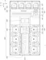
도 1을 참조하면, 기판 처리 설비(1)는 인덱스 모듈(1000)과 공정 처리 모듈(2000)을 포함한다. 인덱스 모듈(1000)은 로드포트(1200) 및 이송프레임(1400)을 포함한다. 로드포트(1200), 이송프레임(1400), 그리고 공정 처리 모듈(2000)은 순차적으로 일렬로 배열된다. 이하, 로드포트(1200), 이송프레임(1400), 그리고 공정 처리 모듈(2000)이 배열된 방향을 제1방향(12)이라 한다. 그리고 상부에서 바라볼 때 제1방향(12)과 수직한 방향을 제2방향(14)이라 하고, 제1방향(12)과 제2방향(14)을 포함한 평면에 수직인 방향을 제3방향(16)이라 한다.Referring to FIG. 1, the substrate processing equipment (1) includes an index module (1000) and a process processing module (2000). The index module (1000) includes a load port (1200) and a transfer frame (1400). The load port (1200), the transfer frame (1400), and the process processing module (2000) are sequentially arranged in a row. Hereinafter, the direction in which the load port (1200), the transfer frame (1400), and the process processing module (2000) are arranged is referred to as a first direction (12). In addition, a direction perpendicular to the first direction (12) when viewed from above is referred to as a second direction (14), and a direction perpendicular to a plane including the first direction (12) and the second direction (14) is referred to as a third direction (16).
로드포트(1200)에는 기판(W)이 수납된 캐리어(1300)가 안착된다. 로드포트(1200)는 복수 개가 제공되며 이들은 제2방향(14)을 따라 일렬로 배치된다. 도 1에서는 네 개의 로드포트(1200)가 제공된 것으로 도시하였다. 그러나 로드포트(1200)의 개수는 공정 처리 모듈(2000)의 공정효율 및 풋 프린트 등의 조건에 따라 증가하거나 감소할 수도 있다. 캐리어(1300)에는 기판(W)의 가장자리를 지지하도록 제공된 슬롯(도시되지 않음)이 형성된다. 슬롯은 제3방향(16)으로 복수 개가 제공된다. 기판(W)은 제3방향(16)을 따라 서로 이격된 상태로 적층되게 캐리어(1300)내에 위치된다. 캐리어(1300)로는 전면 개방 일체형 포드(Front Opening Unified Pod;FOUP)가 사용될 수 있다.A carrier (1300) containing a substrate (W) is placed in the load port (1200). A plurality of load ports (1200) are provided, and they are arranged in a row along the second direction (14). In FIG. 1, four load ports (1200) are provided. However, the number of load ports (1200) may increase or decrease depending on conditions such as process efficiency and footprint of the process processing module (2000). A slot (not shown) is formed in the carrier (1300) to support an edge of the substrate (W). A plurality of slots are provided in the third direction (16). The substrates (W) are positioned in the carrier (1300) so as to be stacked while being spaced apart from each other along the third direction (16). A front opening unified pod (FOUP) can be used as the carrier (1300).
공정 처리 모듈(2000)은 버퍼 유닛(2200), 이송챔버(2400), 그리고 공정챔버(2600)를 포함한다. 이송챔버(2400)는 그 길이 방향이 제1방향(12)과 평행하게 배치된다. 제2방향(14)을 따라 이송챔버(2400)의 일측 및 타측에는 각각 공정챔버들(2600)이 배치된다. 이송챔버(2400)의 일측에 위치한 공정챔버들(2600)과 이송챔버(2400)의 타측에 위치한 공정챔버들(2600)은 이송챔버(2400)를 기준으로 서로 대칭이 되도록 제공된다. 공정챔버(2600)들 중 일부는 이송챔버(2400)의 길이 방향을 따라 배치된다. 또한, 공정챔버(2600)들 중 일부는 서로 적층되게 배치된다. 즉, 이송챔버(2400)의 일측에는 공정챔버(2600)들이 A X B(A와 B는 각각 1이상의 자연수)의 배열로 배치될 수 있다. 여기서 A는 제1방향(12)을 따라 일렬로 제공된 공정챔버(2600)의 수이고, B는 제3방향(16)을 따라 일렬로 제공된 공정챔버(2600)의 수이다. 이송챔버(2400)의 일측에 공정 챔버(2600)가 4개 또는 6개 제공되는 경우, 공정챔버(2600)들은 2 X 2 또는 3 X 2의 배열로 배치될 수 있다. 공정챔버(2600)의 개수는 증가하거나 감소할 수도 있다. 상술한 바와 달리, 공정챔버(2600)는 이송챔버(2400)의 일측에만 제공될 수 있다. 또한, 상술한 바와 달리, 공정챔버(2600)는 이송챔버(2400)의 일측 및 양측에 단층으로 제공될 수 있다.The process processing module (2000) includes a buffer unit (2200), a transfer chamber (2400), and a process chamber (2600). The transfer chamber (2400) is arranged such that its longitudinal direction is parallel to the first direction (12). Process chambers (2600) are arranged on one side and the other side of the transfer chamber (2400) along the second direction (14), respectively. The process chambers (2600) located on one side of the transfer chamber (2400) and the process chambers (2600) located on the other side of the transfer chamber (2400) are provided to be symmetrical with respect to the transfer chamber (2400). Some of the process chambers (2600) are arranged along the longitudinal direction of the transfer chamber (2400). In addition, some of the process chambers (2600) are arranged to be stacked on each other. That is, on one side of the transfer chamber (2400), process chambers (2600) can be arranged in an array of A X B (A and B are each a natural number greater than or equal to 1). Here, A is the number of process chambers (2600) provided in a row along the first direction (12), and B is the number of process chambers (2600) provided in a row along the third direction (16). When four or six process chambers (2600) are provided on one side of the transfer chamber (2400), the process chambers (2600) can be arranged in an array of 2 X 2 or 3 X 2. The number of process chambers (2600) can also increase or decrease. Unlike the above, the process chambers (2600) can be provided only on one side of the transfer chamber (2400). Additionally, unlike the above-described, the process chamber (2600) may be provided as a single layer on one side and both sides of the transfer chamber (2400).
버퍼 유닛(2200)은 이송프레임(1400)과 이송챔버(2400) 사이에 배치된다. 버퍼 유닛(2200)은 이송챔버(2400)와 이송프레임(1400) 간에 기판(W)이 반송되기 전에 기판(W)이 머무르는 공간을 제공한다. 버퍼 유닛(2200)은 그 내부에 기판(W)이 놓이는 슬롯(미도시)이 제공되며, 슬롯(미도시)들은 서로 간에 제3방향(16)을 따라 이격되도록 복수 개 제공된다. 버퍼 유닛(2200)에서 이송프레임(1400)과 마주보는 면과 이송챔버(2400)와 마주보는 면 각각이 개방된다.The buffer unit (2200) is arranged between the transfer frame (1400) and the transfer chamber (2400). The buffer unit (2200) provides a space where the substrate (W) stays before the substrate (W) is returned between the transfer chamber (2400) and the transfer frame (1400). The buffer unit (2200) is provided with a slot (not shown) in which the substrate (W) is placed therein, and a plurality of slots (not shown) are provided so as to be spaced apart from each other along a third direction (16). In the buffer unit (2200), each of a surface facing the transfer frame (1400) and a surface facing the transfer chamber (2400) is open.
이송프레임(1400)은 로드포트(1200)에 안착된 캐리어(1300)와 버퍼 유닛(2200) 간에 기판(W)을 반송한다. 이송프레임(1400)에는 인덱스 레일(1420)과 인덱스 로봇(1440)이 제공된다. 인덱스 레일(1420)은 그 길이 방향이 제2방향(14)과 나란하게 제공된다. 인덱스 로봇(1440)은 인덱스 레일(1420) 상에 설치되며, 인덱스 레일(1420)을 따라 제2방향(14)으로 직선 이동된다. 인덱스 로봇(1440)은 베이스(1441), 몸체(1442), 그리고 인덱스암(1443)을 가진다. 베이스(1441)는 인덱스 레일(1420)을 따라 이동 가능하도록 설치된다. 몸체(1442)는 베이스(1441)에 결합된다. 몸체(1442)는 베이스(1441) 상에서 제3방향(16)을 따라 이동 가능하도록 제공된다. 또한, 몸체(1442)는 베이스(1441) 상에서 회전 가능하도록 제공된다. 인덱스암(1443)은 몸체(1442)에 결합되고, 몸체(1442)에 대해 전진 및 후진 이동 가능하도록 제공된다. 인덱스암(1443)은 복수 개 제공되어 각각 개별 구동되도록 제공된다. 인덱스암(1443)들은 제3방향(16)을 따라 서로 이격된 상태로 적층되게 배치된다. 인덱스암(1443)들 중 일부는 공정 처리 모듈(2000)에서 캐리어(1300)로 기판(W)을 반송할 때 사용되고, 다른 일부는 캐리어(1300)에서 공정 처리 모듈(2000)로 기판(W)을 반송할 때 사용될 수 있다. 이는 인덱스 로봇(1440)이 기판(W)을 반입 및 반출하는 과정에서 공정 처리 전의 기판(W)으로부터 발생된 파티클이 공정 처리 후의 기판(W)에 부착되는 것을 방지할 수 있다.The transfer frame (1400) transfers the substrate (W) between the carrier (1300) mounted on the load port (1200) and the buffer unit (2200). The transfer frame (1400) is provided with an index rail (1420) and an index robot (1440). The index rail (1420) is provided such that its longitudinal direction is parallel to the second direction (14). The index robot (1440) is installed on the index rail (1420) and moves linearly along the index rail (1420) in the second direction (14). The index robot (1440) has a base (1441), a body (1442), and an index arm (1443). The base (1441) is installed so as to be able to move along the index rail (1420). The body (1442) is coupled to the base (1441). The body (1442) is provided to be movable along the third direction (16) on the base (1441). In addition, the body (1442) is provided to be rotatable on the base (1441). An index arm (1443) is coupled to the body (1442) and is provided to be movable forward and backward with respect to the body (1442). A plurality of index arms (1443) are provided so as to be individually driven. The index arms (1443) are arranged to be stacked while being spaced apart from each other along the third direction (16). Some of the index arms (1443) may be used when returning a substrate (W) from a process processing module (2000) to a carrier (1300), and other some may be used when returning a substrate (W) from a carrier (1300) to the process processing module (2000). This can prevent particles generated from the substrate (W) before processing from being attached to the substrate (W) after processing during the process of the index robot (1440) loading and unloading the substrate (W).
이송챔버(2400)는 버퍼 유닛(2200)과 공정챔버(2600) 간에, 그리고 공정챔버(2600)들 간에 기판(W)을 반송한다. 이송챔버(2400)에는 가이드 레일(2420)과 메인로봇(2440)이 제공된다. 가이드 레일(2420)은 그 길이 방향이 제1방향(12)과 나란 하도록 배치된다. 메인로봇(2440)은 가이드 레일(2420) 상에 설치되고, 가이드 레일(2420) 상에서 제1방향(12)을 따라 직선 이동된다. 메인로봇(2440)은 베이스(2441), 몸체(2442), 그리고 메인암(2443)을 가진다. 베이스(2441)는 가이드 레일(2420)을 따라 이동 가능하도록 설치된다. 몸체(2442)는 베이스(2441)에 결합된다. 몸체(2442)는 베이스(2441) 상에서 제3방향(16)을 따라 이동 가능하도록 제공된다. 또한, 몸체(2442)는 베이스(2441) 상에서 회전 가능하도록 제공된다. 메인암(2443)은 몸체(2442)에 결합되고, 이는 몸체(2442)에 대해 전진 및 후진 이동 가능하도록 제공된다. 메인암(2443)은 복수 개 제공되어 각각 개별 구동 되도록 제공된다. 메인암(2443)들은 제3방향(16)을 따라 서로 이격된 상태로 적층되게 배치된다. 버퍼 유닛(2200)에서 공정챔버(2600)로 기판(W)을 반송할 때 사용되는 메인암(2443)과 공정챔버(2600)에서 버퍼 유닛(2200)으로 기판(W)을 반송할 때 사용되는 메인암(2443)은 서로 상이할 수 있다.The transfer chamber (2400) transfers a substrate (W) between the buffer unit (2200) and the process chamber (2600), and between the process chambers (2600). A guide rail (2420) and a main robot (2440) are provided in the transfer chamber (2400). The guide rail (2420) is arranged so that its longitudinal direction is parallel to the first direction (12). The main robot (2440) is installed on the guide rail (2420) and moves linearly along the first direction (12) on the guide rail (2420). The main robot (2440) has a base (2441), a body (2442), and a main arm (2443). The base (2441) is installed so as to be able to move along the guide rail (2420). The body (2442) is coupled to the base (2441). The body (2442) is provided to be movable along the third direction (16) on the base (2441). In addition, the body (2442) is provided to be rotatable on the base (2441). The main arm (2443) is coupled to the body (2442) and is provided to be movable forward and backward with respect to the body (2442). The main arms (2443) are provided in multiple numbers and are provided to be individually driven. The main arms (2443) are arranged to be stacked while being spaced apart from each other along the third direction (16). The main arm (2443) used when returning the substrate (W) from the buffer unit (2200) to the process chamber (2600) and the main arm (2443) used when returning the substrate (W) from the process chamber (2600) to the buffer unit (2200) may be different from each other.
공정챔버(2600) 내에는 기판(W)에 대해 세정 공정을 수행하는 기판 처리 장치(10)가 제공된다. 각각의 공정챔버(2600) 내에 제공된 기판 처리 장치(10)는 수행하는 세정 공정의 종류에 따라 상이한 구조를 가질 수 있다. 선택적으로 각각의 공정챔버(2600) 내의 기판 처리 장치(10)는 동일한 구조를 가질 수 있다. 선택적으로 공정챔버(2600)들은 복수 개의 그룹으로 구분되어, 동일한 그룹에 속하는 공정챔버(2600)에 제공된 기판 처리 장치(10)들은 서로 동일한 구조를 가지고, 상이한 그룹에 속하는 공정챔버(2600)에 제공된 기판 처리 장치(10)들은 서로 상이한 구조를 가질 수 있다. 예컨대, 공정챔버(2600)가 2개의 그룹으로 나누어지는 경우, 이송챔버(2400)의 일측에는 제1그룹의 공정챔버들(2600)이 제공되고, 이송챔버(2400)의 타측에는 제2그룹의 공정챔버들(2600)이 제공될 수 있다. 선택적으로 이송챔버(2400)의 일측 및 타측 각각에서 하층에는 제1그룹의 공정챔버(2600)들이 제공되고, 상층에는 제2그룹의 공정챔버(2600)들이 제공될 수 있다. 제1그룹의 공정챔버(2600)와 제2그룹의 공정챔버(2600)는 각각 사용되는 케미칼의 종류나, 세정 방식의 종류에 따라 구분될 수 있다.A substrate processing device (10) for performing a cleaning process on a substrate (W) is provided within a process chamber (2600). The substrate processing device (10) provided within each process chamber (2600) may have a different structure depending on the type of cleaning process to be performed. Optionally, the substrate processing devices (10) within each process chamber (2600) may have the same structure. Optionally, the process chambers (2600) are divided into a plurality of groups, and the substrate processing devices (10) provided within the process chambers (2600) belonging to the same group may have the same structure, and the substrate processing devices (10) provided within the process chambers (2600) belonging to different groups may have different structures. For example, when the process chamber (2600) is divided into two groups, the first group of process chambers (2600) may be provided on one side of the transfer chamber (2400), and the second group of process chambers (2600) may be provided on the other side of the transfer chamber (2400). Optionally, the first group of process chambers (2600) may be provided on the lower layer on each of the one side and the other side of the transfer chamber (2400), and the second group of process chambers (2600) may be provided on the upper layer. The first group of process chambers (2600) and the second group of process chambers (2600) may be distinguished according to the type of chemical used or the type of cleaning method.
아래의 실시예에서는 고온의 황산, 알카리성 약액, 산성 약액, 린스액, 고온의 순수 그리고 건조 가스와 같은 처리 유체들을 사용하여 기판(W)을 세정하는 장치를 예로 들어 설명한다. 그러나 본 발명의 기술적 사상은 이에 한정되지 않으며, 식각 공정 등과 같이 기판(W)을 회전시키면서 공정을 수행하는 다양한 종류의 장치에 모두 적용될 수 있다.In the following examples, a device for cleaning a substrate (W) using processing fluids such as high-temperature sulfuric acid, alkaline solutions, acidic solutions, rinse solutions, high-temperature pure water, and drying gas is described as an example. However, the technical idea of the present invention is not limited thereto, and can be applied to various types of devices that perform a process while rotating the substrate (W), such as an etching process.
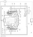
도 2는 도 1의 기판 처리 장치의 평면도이고, 도 3은 도 1의 기판 처리 장치의 단면도이다.Figure 2 is a plan view of the substrate processing device of Figure 1, and Figure 3 is a cross-sectional view of the substrate processing device of Figure 1.
도 2와 도 3을 참조하면, 기판 처리 장치(10)는 챔버(100), 바울(200), 지지 유닛(300), 가열유체 공급 유닛(330), 처리액 공급 유닛(410), 배기 유닛(500), 승강 유닛(600), 히터(700), 제어기(800)를 포함할 수 있다.Referring to FIGS. 2 and 3, the substrate processing device (10) may include a chamber (100), a bowl (200), a support unit (300), a heating fluid supply unit (330), a processing liquid supply unit (410), an exhaust unit (500), an elevating unit (600), a heater (700), and a controller (800).
챔버(100)는 밀폐된 내부 공간을 제공한다. 상부에는 기류 공급 부재(110)가 설치된다. 기류 공급 부재(110)은 챔버(100) 내부에 하강 기류를 형성한다.The chamber (100) provides a sealed internal space. An airflow supply member (110) is installed at the top. The airflow supply member (110) forms a descending airflow inside the chamber (100).
기류 공급 부재(110)는 고습도 외기를 필터링하여 챔버(100) 내부로 공급한다. 고습도 외기는 기류 공급 부재(110)를 통과하여 챔버(100) 내부로 공급되며 하강 기류를 형성한다. 하강 기류는 기판(W)의 상부에 균일한 기류를 제공하며, 처리 유체에 의해 기판(W) 표면이 처리되는 과정에서 발생되는 오염물질들을 공기와 함께 바울(200)의 회수통들(210,220,230)을 통해 배기 유닛(500)으로 배출시킨다.The air supply member (110) filters high-humidity outside air and supplies it into the chamber (100). The high-humidity outside air passes through the air supply member (110) and is supplied into the chamber (100) to form a descending airflow. The descending airflow provides a uniform airflow to the upper portion of the substrate (W) and discharges contaminants generated during the process of treating the surface of the substrate (W) with the treatment fluid together with air to the exhaust unit (500) through the recovery tanks (210, 220, 230) of the bowl (200).
챔버(100)는 수평 격벽(102)에 의해 공정 영역(120)과 유지보수 영역(130)으로 나뉜다. 공정 영역(120)에는 바울(200)과 지지 유닛(300)이 위치한다. 유지보수 영역(130)에는 바울(200)과 연결되는 회수 라인(241,243,245), 배기 라인(510) 이외에도 승강 유닛(600)의 구동부과, 처리액 공급 유닛(410)과 연결되는 구동부, 공급라인 등이 위치한다. 유지보수 영역(130)은 공정 영역(120)으로부터 격리된다.The chamber (100) is divided into a process area (120) and a maintenance area (130) by a horizontal bulkhead (102). A bowl (200) and a support unit (300) are located in the process area (120). In addition to a recovery line (241, 243, 245) and an exhaust line (510) connected to the bowl (200), a driving unit of an elevating unit (600), a driving unit connected to a treatment liquid supply unit (410), a supply line, etc. are located in the maintenance area (130). The maintenance area (130) is isolated from the process area (120).
지지 유닛(300)은 공정 진행 중 기판(W)을 지지하며, 공정이 진행되는 동안 기판(W)을 회전시킬 수 있다. 지지 유닛(300)은 지지판(310) 및 스핀 구동부(320)를 포함할 수 있다.The support unit (300) supports the substrate (W) during the process and can rotate the substrate (W) while the process is in progress. The support unit (300) may include a support plate (310) and a spin drive unit (320).
지지판(310)은 원형의 상부면을 가진다. 지지판(310)는 스핀 구동부 (320)에 결합되어 회전된다. 지지판(310)은 지지 핀(318)들을 포함한다. 지지 핀(318)들은 지지판(310)의 상부 면 가장자리부에 소정 간격 이격되어 배치될 수 있다. 지지 핀(318)들은 기판(W)의 하면을 지지하여 기판(W)이 지지판(310)로부터 상측 방향으로 이격된 상태에서 지지되도록 한다. 지지판(310)의 가장자리에는 척킹 핀(316)들이 설치된다. 척킹 핀(316)들은 다수의 지지 핀(318)들에 의해 지지된 기판(W)이 정 위치에 놓이도록 기판(W)을 정렬한다. 공정 진행시 척킹 핀(316)들은 기판(W)의 측부와 접촉되어 기판(W)이 정 위치로부터 이탈되는 것을 방지한다. 스핀 구동부(320)는 중공형의 형상을 갖고, 지지판(310)과 결합하여 지지판(310)을 회전시킨다.The support plate (310) has a circular upper surface. The support plate (310) is coupled to a spin driver (320) and rotates. The support plate (310) includes support pins (318). The support pins (318) may be arranged at an edge portion of the upper surface of the support plate (310) at a predetermined interval. The support pins (318) support the lower surface of the substrate (W) so that the substrate (W) is supported while being spaced upward from the support plate (310). Chucking pins (316) are installed at the edge of the support plate (310). The chucking pins (316) align the substrate (W) supported by the plurality of support pins (318) so that the substrate (W) is placed in a correct position. During the process, the chucking pins (316) come into contact with the side of the substrate (W) to prevent the substrate (W) from being deviated from the correct position. The spin drive unit (320) has a hollow shape and is combined with the support plate (310) to rotate the support plate (310).
처리액 공급 유닛(410)은 기판의 패턴면의 박막으로 처리액을 분사하기 위해 제공된다. 처리액은 기판(W) 표면의 박막을 식각하기 위한 고온의 케미칼일 수 있다. 일 예로, 박막은 질화티타늄(TiN)막일 수 있고, 식각액은 과산화수소 또는 과산화수소와 알칼리액의 혼합액을 포함할 수 있다.The treatment solution supply unit (410) is provided to spray the treatment solution onto the thin film on the pattern surface of the substrate. The treatment solution may be a high-temperature chemical for etching the thin film on the surface of the substrate (W). As an example, the thin film may be a titanium nitride (TiN) film, and the etching solution may include hydrogen peroxide or a mixture of hydrogen peroxide and an alkaline solution.
처리액 공급 유닛(410)은 제1노즐(411), 노즐 암(413), 지지 로드(415), 노즐 구동기(417)를 포함할 수 있다. 제1노즐(411)은 공급부(420)를 통해 식각액을 공급받는다. 제1노즐(411)은 식각액을 기판(W)의 패턴면으로 토출한다. 노즐 암(413)은 일 방향으로 길이가 길게 제공되는 암으로, 선단에 제1노즐(411)이 장착된다. 노즐 암(413)은 제1노즐(411)을 지지한다. 노즐 암(413)의 후단에는 지지 로드(415)가 장착된다. 지지 로드(415)는 노즐 암(413)의 하부에 위치한다. 지지 로드(415)는 노즐 암(413)에 수직하게 배치된다. 노즐 구동기(417)는 지지 로드(415)의 하단에 제공된다. 노즐 구동기(417)는 지지 로드(415)의 길이 방향 축을 중심으로 지지 로드(415)를 회전시킨다. 지지 로드(415)의 회전으로 노즐 암(413)과 제1노즐(411)이 지지 로드(415)를 축으로 스윙 이동한다. 제1노즐(411)은 바울(200)의 외측과 내측 사이를 스윙 이동할 수 있다.The treatment solution supply unit (410) may include a first nozzle (411), a nozzle arm (413), a support rod (415), and a nozzle driver (417). The first nozzle (411) receives an etchant through a supply unit (420). The first nozzle (411) discharges the etchant onto a pattern surface of a substrate (W). The nozzle arm (413) is an arm that is provided long in one direction, and a first nozzle (411) is mounted at a front end thereof. The nozzle arm (413) supports the first nozzle (411). A support rod (415) is mounted at the rear end of the nozzle arm (413). The support rod (415) is located at the lower end of the nozzle arm (413). The support rod (415) is arranged vertically to the nozzle arm (413). The nozzle driver (417) is provided at the lower end of the support rod (415). The nozzle driver (417) rotates the support rod (415) around the longitudinal axis of the support rod (415). As the support rod (415) rotates, the nozzle arm (413) and the first nozzle (411) swing about the support rod (415). The first nozzle (411) can swing between the outside and inside of the bowl (200).
도시하지 않았지만, 챔버(100)에는 기판으로 린스액을 공급하기 위한 린스액 공급 유닛이 제공될 수 있으며, 린스액 공급 유닛은 처리액 공급 유닛과 거의 동일한 구성으로 제공될 수 있으며, 이에 대한 설명은 생략하기로 한다.Although not described herein, a rinse solution supply unit for supplying a rinse solution to the substrate may be provided in the chamber (100), and the rinse solution supply unit may be provided with a configuration almost identical to that of the treatment solution supply unit, and a description thereof will be omitted.
가열유체 공급 유닛(330)은 노즐 몸체(332) 및 백노즐 분사부(334)를 포함할 수 있다. 백노즐 분사부(334)는 지지판(310)의 중앙 상부에 위치된다. 백노즐 분사부(334)는 가열 유체를 기판의 비패턴면 중심으로 토출한다. 백노즐 분사부(334)는 고온의 린스액(초순수)을 분사할 수 있다. 노즐 몸체(332)는 중공형의 스핀 구동부(320) 내에 관통 축설된다. 도시하지 않았지만, 노즐 몸체(334)의 내부에는 가열 유체 공급 라인, 린스액 공급 라인 등이 제공될 수 있다. 백노즐 분사부(334)는 가열 유체 공급부(339)를 통해 가열 유체를 공급받는다.The heating fluid supply unit (330) may include a nozzle body (332) and a back nozzle spray unit (334). The back nozzle spray unit (334) is located at the upper center of the support plate (310). The back nozzle spray unit (334) sprays a heating fluid toward the center of a non-patterned surface of the substrate. The back nozzle spray unit (334) may spray a high-temperature rinsing liquid (ultra-pure water). The nozzle body (332) is installed through a hollow spin drive unit (320). Although not shown, a heating fluid supply line, a rinsing liquid supply line, etc. may be provided inside the nozzle body (334). The back nozzle spray unit (334) receives a heating fluid through a heating fluid supply unit (339).
제어기(800)는 기판 처리 장치를 제어할 수 있다. 제어기(800)는 상술하는 바와 같이 기판을 설정 공정에 따라 처리되도록 공정 챔버의 구성 요소들을 제어할 수 있다. 또한, 제어기(800)는 기판 처리 장치의 제어를 실행하는 마이크로프로세서(컴퓨터)로 이루어지는 프로세스 컨트롤러와, 오퍼레이터가 기판 처리 장치를 관리하기 위해서 커맨드 입력 조작 등을 행하는 키보드나, 기판 처리 장치의 가동 상황을 가시화해서 표시하는 디스플레이 등으로 이루어지는 유저 인터페이스와, 기판 처리 장치에서 실행되는 처리를 프로세스 컨트롤러의 제어로 실행하기 위한 제어 프로그램이나, 각종 데이터 및 처리 조건에 따라 각 구성부에 처리를 실행시키기 위한 프로그램, 즉 처리 레시피가 저장된 기억부를 구비할 수 있다. 또한, 유저 인터페이스 및 기억부는 프로세스 컨트롤러에 접속되어 있을 수 있다. 처리 레시피는 기억 부 중 기억 매체에 기억되어 있을 수 있고, 기억 매체는, 하드 디스크이어도 되고, CD-ROM, DVD 등의 가반성 디스크나, 플래시 메모리 등의 반도체 메모리 일 수도 있다.The controller (800) can control the substrate processing device. The controller (800) can control the components of the process chamber so that the substrate is processed according to the set process as described above. In addition, the controller (800) may be equipped with a process controller including a microprocessor (computer) that executes control of the substrate processing device, a user interface including a keyboard through which an operator performs command input operations, etc. to manage the substrate processing device, a display that visualizes and displays the operating status of the substrate processing device, a control program for executing processing executed in the substrate processing device under the control of the process controller, or a memory unit in which a program for executing processing in each component according to various data and processing conditions, i.e., a processing recipe, is stored. In addition, the user interface and the memory unit may be connected to the process controller. The processing recipe may be stored in a storage medium among the memory units, and the storage medium may be a hard disk, a portable disk such as a CD-ROM or DVD, or a semiconductor memory such as a flash memory.
바울(200)은 상부가 개방된 원통 형상을 갖고, 기판(W)을 처리하기 위한 처리 공간을 가진다. 바울(200)의 개방된 상면은 기판(W)의 반출 및 반입 통로로 제공된다. 처리 공간에는 지지 유닛(300)이 위치된다. 지지 유닛(300)은 공정 진행시 기판(W)을 지지한 상태에서 기판(W)을 회전시킨다.The bowl (200) has a cylindrical shape with an open top and has a processing space for processing a substrate (W). The open upper surface of the bowl (200) is provided as a passage for taking out and bringing in the substrate (W). A support unit (300) is positioned in the processing space. The support unit (300) rotates the substrate (W) while supporting the substrate (W) during the process.
바울(200)은 강제 배기가 이루어지도록 하단부에 배기 덕트(290)가 연결된 하부공간을 제공한다. 바울(200)에는 회전되는 기판(W)상에서 비산되는 처리액과 기체를 유입 및 흡입하는 제1 내지 제3회수통(210, 220, 230)이 다단으로 배치된다.The bowl (200) provides a lower space with an exhaust duct (290) connected to the lower portion to enable forced exhaust. The bowl (200) is provided with first to third recovery tanks (210, 220, 230) arranged in multiple stages to introduce and suck in the treatment liquid and gas flying on the rotating substrate (W).
환형의 제1 내지 제3회수통(210, 220, 230)은 하나의 공통된 환형 공간과 통하는 배기구(H)들을 갖는다. 구체적으로, 제1 내지 제3회수통(210, 220, 230)은 각각 환형의 링 형상을 갖는 바닥면 및 바닥면으로부터 연장되어 원통 형상을 갖는 측벽을 포함한다. 제2회수통(220)은 제1회수통(210)을 둘러싸고, 제1회수통(210)로부터 이격되어 위치한다. 제3회수통(230)은 제2회수통(220)을 둘러싸고, 제2회수통(220)로부터 이격되어 위치한다.The first to third annular recovery tanks (210, 220, 230) have exhaust ports (H) communicating with a common annular space. Specifically, the first to third recovery tanks (210, 220, 230) each include a bottom surface having an annular ring shape and a side wall extending from the bottom surface and having a cylindrical shape. The second recovery tank (220) surrounds the first recovery tank (210) and is positioned apart from the first recovery tank (210). The third recovery tank (230) surrounds the second recovery tank (220) and is positioned apart from the second recovery tank (220).
제1 내지 제3회수통 (210, 220, 230)은 기판(W)으로부터 비산된 처리액 및 흄이 포함된 기류가 유입되는 제1 내지 제3회수공간(RS1, RS2, RS3)을 제공한다. 제1회수공간(RS1)은 제1회수통(110)에 의해 정의되고, 제2회수공간(RS2)은 제1 회수통(110)과 제2회수통(120) 간의 이격 공간에 의해 정의되며, 제3회수공간(RS3)은 제2회수통(120)과 제3회수통(130) 간의 이격 공간에 의해 정의된다.The first to third recovery tanks (210, 220, 230) provide first to third recovery spaces (RS1, RS2, RS3) into which airflow containing the treatment liquid and fume flying from the substrate (W) flows in. The first recovery space (RS1) is defined by the first recovery tank (110), the second recovery space (RS2) is defined by the space between the first recovery tank (110) and the second recovery tank (120), and the third recovery space (RS3) is defined by the space between the second recovery tank (120) and the third recovery tank (130).
제1 내지 제3회수통(210, 220, 230)의 각 상면은 중앙부가 개방된다. 제1 내지 제3회수통(210, 220, 230)은 연결된 수직벽(202)(측벽)으로부터 개방부로 갈수록 대응하는 바닥면과의 거리가 점차 증가하는 경사벽(204)으로 이루어진다. 기판(W)으로부터 비산된 처리액은 제1 내지 제3회수통(210, 220, 230)의 유입구를 따라 회수 공간들(RS1, RS2, RS3) 안으로 흘러간다.The upper surface of each of the first to third recovery tanks (210, 220, 230) is open in the center. The first to third recovery tanks (210, 220, 230) are formed by inclined walls (204) in which the distance from the corresponding bottom surface gradually increases from the connected vertical wall (202) (side wall) toward the open portion. The treatment liquid flying from the substrate (W) flows into the recovery spaces (RS1, RS2, RS3) along the inlets of the first to third recovery tanks (210, 220, 230).
액 처리 공정이 진행시 기판(W)의 회전에 의해 비산되는 처리 액은 제1 내지 제3회수통(210, 220, 230)의 유입구(210a, 220a, 230a)를 통해 회수 공간(RS1, RS2, RS3)으로 유입될 수 있다. 일 예에 의하면, 제1회수통(210)은 지지 유닛(300)을 감싸도록 배치되고, 제2회수통(220)은 제1회수통(210)을 감싸도록 배치되고, 제3회수통(230)은 제2회수통(220)을 감싸도록 배치된다. 제2회수통(220)의 제2유입구(220a)는 제1회수통(210)의 제1유입구(210a)보다 상부에 위치되고, 제3회수통(230)의 제3유입구(230a)는 제2유입구(220a)보다 상부에 위치될 수 있다. 제1회수공간(RS1)에 유입된 제1처리액은 제1회수라인(241)을 통해 외부로 배출된다. 제2회수공간(RS2)에 유입된 제2처리액은 제2회수라인(243)을 통해 외부로 배출된다. 제3회수공간(RS3)에 유입된 제3처리액은 제3회수라인(245)을 통해 외부로 배출된다.When the liquid treatment process is in progress, the treatment liquid scattered by the rotation of the substrate (W) can be introduced into the recovery space (RS1, RS2, RS3) through the inlets (210a, 220a, 230a) of the first to third recovery tanks (210, 220, 230). According to an example, the first recovery tank (210) is arranged to surround the support unit (300), the second recovery tank (220) is arranged to surround the first recovery tank (210), and the third recovery tank (230) is arranged to surround the second recovery tank (220). The second inlet (220a) of the second recovery tank (220) may be positioned above the first inlet (210a) of the first recovery tank (210), and the third inlet (230a) of the third recovery tank (230) may be positioned above the second inlet (220a). The first treatment liquid flowing into the first recovery space (RS1) is discharged to the outside through the first recovery line (241). The second treatment liquid flowing into the second recovery space (RS2) is discharged to the outside through the second recovery line (243). The third treatment liquid flowing into the third recovery space (RS3) is discharged to the outside through the third recovery line (245).
배기 유닛(500)은 바울(200)의 내부를 배기할 수 있다. 일 예로, 배기 유닛(500)은 공정시 제1 내지 제3회수통(210, 220, 230)중 처리액을 회수하는 회수통에 배기 압력(흡입 압력)을 제공하기 위한 것이다. 배기 유닛(500)은 배기 덕트(290)와 연결되는 배기 라인(510), 댐퍼(520)를 포함한다. 배기 라인(510)은 배기 펌프(미도시됨)로부터 배기압을 제공받으며 반도체 생산라인의 바닥 공간에 매설된 메인 배기 라인과 연결된다.The exhaust unit (500) can exhaust the inside of the bowl (200). For example, the exhaust unit (500) is provided to provide exhaust pressure (suction pressure) to the recovery tanks that recover the treatment liquid among the first to third recovery tanks (210, 220, 230) during the process. The exhaust unit (500) includes an exhaust line (510) connected to an exhaust duct (290) and a damper (520). The exhaust line (510) receives exhaust pressure from an exhaust pump (not shown) and is connected to a main exhaust line buried in the floor space of a semiconductor production line.
한편, 바울(200)은 바울(200)의 수직 위치를 변경시키는 승강 유닛(600)과 결합된다. 승강 유닛(600)은 바울(200)을 상하 방향으로 직선 이동시킨다. 바울(200)이 상하로 이동됨에 따라 지지 유닛(300)에 대한 바울(200)의 상대 높이가 변경된다.Meanwhile, the pole (200) is coupled with an elevating unit (600) that changes the vertical position of the pole (200). The elevating unit (600) moves the pole (200) in a straight line in the up-and-down direction. As the pole (200) moves up and down, the relative height of the pole (200) with respect to the support unit (300) changes.
승강 유닛(600)은 브라켓(612), 이동 축(614), 그리고 구동기(616)를 포함한다. 브라켓(612)은 처리 용기(100)의 외벽에 고정 설치된다. 브라켓(612)에는 구동기(616)에 의해 상하 방향으로 이동되는 이동 축(614)이 고정 결합된다. 기판(W)이 지지 유닛(300)에 로딩 또는 언 로딩될 때 지지 유닛(300)이 바울(200)의 상부로 돌출되도록 바울(200)은 하강한다. 또한, 공정이 진행 시에는 기판(W)에 공급된 처리액의 종류에 따라 처리액이 기 설정된 회수통들(210, 220, 230)로 유입될 수 있도록 바울(200)의 높이가 조절된다. 바울(200)은 상기 각 회수공간(RS1, RS2, RS3) 별로 회수되는 처리액과 오염 가스의 종류를 다르게 할 수 있다.The lifting unit (600) includes a bracket (612), a moving shaft (614), and a driver (616). The bracket (612) is fixedly installed on the outer wall of the processing vessel (100). A moving shaft (614) that moves up and down by a driver (616) is fixedly connected to the bracket (612). When the substrate (W) is loaded or unloaded on the support unit (300), the bail (200) is lowered so that the support unit (300) protrudes above the bail (200). In addition, when the process is in progress, the height of the bail (200) is adjusted so that the processing liquid supplied to the substrate (W) can flow into preset recovery containers (210, 220, 230) according to the type of the processing liquid. The bail (200) can have different types of the processing liquid and the polluted gas recovered for each recovery space (RS1, RS2, RS3).
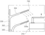
도 4는 히터를 설명하기 위한 도면이다.Figure 4 is a drawing for explaining a heater.
도 4를 참조하면, 히터(700)는 기판 가장자리의 온도를 보상하기 위해 제공된다. 히터(700)는 바울(200)에 제공될 수 있다. 히터(700)는 기판 가장자리와 가까운 제1 내지 제3회수통(210, 220, 230)의 경사벽(204)에 설치될 수 있다. 일 예로, 히터(700)는 제3회수통(230)의 경사벽(204) 내측면에 제공될 수 있다. 그러나, 히터(700) 배치는 이에 한정되는 것은 아니고 제1,2회수통(210,220)의 경사벽(204)에도 제공될 수 있다. 히터(700)에 의해 기판 가장자리는 승온될 수 있다. 특히, 식각액을 이용한 기판 처리시 기판으로부터 비산되는 식각액이 히터(700)에 의해 가열된 바울(200)의 경사벽(204)에 맞고 기판으로 리바운드되는 과정에서 리바운드되는 식각액의 온도가 상승되는 효과가 있어, 기판 가장자FL의 온도를 상승시키는 효꽈를 기대할 수 있다. 히터(700)의 발열체는 램프(lamp), UV 광원, LED 광원, 레이저 광원, 또는 열선(hot wire) 중 어느 하나를 포함할 수 있다.Referring to FIG. 4, a heater (700) is provided to compensate for the temperature of the edge of the substrate. The heater (700) may be provided in the bowl (200). The heater (700) may be installed on the inclined wall (204) of the first to third recovery tanks (210, 220, 230) close to the edge of the substrate. For example, the heater (700) may be provided on the inner surface of the inclined wall (204) of the third recovery tank (230). However, the arrangement of the heater (700) is not limited thereto and may also be provided on the inclined wall (204) of the first and second recovery tanks (210, 220). The edge of the substrate may be heated by the heater (700). In particular, when the etchant flying from the substrate during substrate processing using an etchant hits the inclined wall (204) of the bowl (200) heated by the heater (700) and rebounds to the substrate, the temperature of the rebounding etchant increases, so that the effect of increasing the temperature of the edge FL of the substrate can be expected. The heating element of the heater (700) may include any one of a lamp, a UV light source, an LED light source, a laser light source, or a hot wire.
도 5 및 도 6은 본 발명의 일 실시 예에 따라 기판이 처리되는 과정을 설명하기 위한 플로우챠트 및 도면이다. 도 5, 도 6을 참조하여 본 발명의 일 실시 예에 따른 기판 처리 방법을 설명한다.FIGS. 5 and 6 are flowcharts and drawings for explaining a process of processing a substrate according to one embodiment of the present invention. A substrate processing method according to one embodiment of the present invention will be explained with reference to FIGS. 5 and 6.
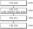
기판 처리 방법은 기판 로딩 단계(S100), 기판 식각 단계(S200), 기판 린스 단계(S300) 그리고 기판 건조 단계(S400)를 포함할 수 있다. 기판 로딩 단계(S100)에서 기판은 챔버(100)로 반입되어 지지 유닛(300)에 놓여진다. 기판이 지지 유닛(300)에 기판이 놓여지면, 약액 처리 공정(기판 식각 단계;S200)을 수행한다. 약액 처리 공정(식각 단계)은 기판이 회전되는 상태에서 처리액 공급 유닛(410)의 제1노즐(411)이 기판의 패턴면으로 식각액을 공급하고, 가열 유체 공급 유닛(330)의 백노즐 분사부(334)가 기판의 비패턴면으로 가열 유체인 고온의 초순수를 공급한다. 가열 유체의 공급 시점은 식각액의 공급 시점보다 빠르거나 같을 수 있다. 식각액은 고온(예를 들면, 섭씨 50도)으로 공급될 수 있고, 식각액은 기판의 패턴면 중심으로 토출될 수 있다. 약액 처리 공정에서 기판 가장자리는 히터(700)에 의해 승온될 수 있다. 따라서, 기판의 가장자리 영역의 온도는 기판의 중심 영역의 온도보다 소정온도 높아질 수 있다. 이처럼, 약액 처리 공정시 히터(700)에 의해 기판 가장자리 온도가 기판 중심 온도보다 소정 온도 높게 유지됨으로써 개선전보다 식각 E/R 산포를 개선할 수 있다.The substrate processing method may include a substrate loading step (S100), a substrate etching step (S200), a substrate rinsing step (S300), and a substrate drying step (S400). In the substrate loading step (S100), the substrate is loaded into the chamber (100) and placed on the support unit (300). When the substrate is placed on the support unit (300), a chemical treatment process (substrate etching step; S200) is performed. In the chemical treatment process (etching step), the first nozzle (411) of the treatment solution supply unit (410) supplies an etching solution to the pattern surface of the substrate while the substrate is rotated, and the back nozzle spray unit (334) of the heating fluid supply unit (330) supplies high-temperature ultrapure water as a heating fluid to the non-pattern surface of the substrate. The supply time of the heating fluid may be earlier than or the same as the supply time of the etching solution. The etchant can be supplied at a high temperature (for example, 50 degrees Celsius), and the etchant can be discharged to the center of the pattern surface of the substrate. In the liquid treatment process, the edge of the substrate can be heated by the heater (700). Therefore, the temperature of the edge region of the substrate can be higher by a predetermined temperature than the temperature of the center region of the substrate. In this way, the substrate edge temperature is maintained by the heater (700) higher than the substrate center temperature during the liquid treatment process, thereby improving the etching E/R distribution compared to before the improvement.
기판에 대한 식각 공정이 완료되면 린스 단계(S300)가 수행될 수 있다. 린스 단계는 기판의 패턴면으로 순수가 공급될 수 있다. 이 후, 기판(W)은 건조 단계(S400)가 수행될 수 있다. 건조 단계(S400)는 스핀 드라이 또는, 초임계 건조 등이 적용될 수 있다.When the etching process for the substrate is completed, a rinsing step (S300) may be performed. In the rinsing step, pure water may be supplied to the pattern surface of the substrate. After this, the substrate (W) may be subjected to a drying step (S400). The drying step (S400) may be applied by spin drying or supercritical drying.
도 7은 기판 가장자리의 온도 보상을 통한 에칭 레이트의 균일도((E/R Uniformity)를 보여주는 그래프이다.Figure 7 is a graph showing the uniformity of the etching rate (E/R Uniformity) through temperature compensation at the edge of the substrate.
도 7을 참고하면, 본 발명은 기판이 지지 유닛에 놓이고, 고온의 식각액이 기판의 패턴면을 향해 토출될 때 회수통에 설치된 히터에 의해 기판 가장자리의 온도 보상이 이루어진다. 따라서, 기판 가장자리 온도가 기판 중심 온도보다 소정 온도 높게 유지됨으로써 개선전보다 식각 E/R 산포를 개선할 수 있다.Referring to FIG. 7, the present invention provides temperature compensation at the edge of the substrate by a heater installed in a recovery tank when the substrate is placed on a support unit and a high-temperature etchant is discharged toward the pattern surface of the substrate. Accordingly, the temperature at the edge of the substrate is maintained at a predetermined temperature higher than the temperature at the center of the substrate, thereby improving the etching E/R distribution compared to before the improvement.
이상의 상세한 설명은 본 발명을 예시하는 것이다. 또한 전술한 내용은 본 발명의 바람직한 실시 형태를 나타내어 설명하는 것이며, 본 발명은 다양한 다른 조합, 변경 및 환경에서 사용할 수 있다. 즉 본 명세서에 개시된 발명의 개념의 범위, 저술한 개시 내용과 균등한 범위 및/또는 당업계의 기술 또는 지식의 범위내에서 변경 또는 수정이 가능하다. 저술한 실시예는 본 발명의 기술적 사상을 구현하기 위한 최선의 상태를 설명하는 것이며, 본 발명의 구체적인 적용 분야 및 용도에서 요구되는 다양한 변경도 가능하다. 따라서 이상의 발명의 상세한 설명은 개시된 실시 상태로 본 발명을 제한하려는 의도가 아니다. 또한 첨부된 청구범위는 다른 실시 상태도 포함하는 것으로 해석되어야 한다.The above detailed description is illustrative of the present invention. In addition, the above contents illustrate and explain the preferred embodiment of the present invention, and the present invention can be used in various other combinations, changes, and environments. That is, changes or modifications are possible within the scope of the inventive concept disclosed in this specification, the scope equivalent to the written disclosure, and/or the scope of technology or knowledge in the art. The written embodiment describes the best state for implementing the technical idea of the present invention, and various changes required for specific application fields and uses of the present invention are also possible. Therefore, the above detailed description of the invention is not intended to limit the present invention to the disclosed embodiments. In addition, the appended claims should be interpreted to include other embodiments.
100: 챔버
200: 바울
300: 지지 유닛
410: 처리액 공급 유닛
500: 배기 유닛
700 : 히터
800 : 제어기100: Chamber
200: Paul
300: Support Unit
410: Treatment liquid supply unit
500: Exhaust unit
700 : Heater
800 : Controller
Claims (10)
Translated fromKorean챔버의 처리 공간에 위치하는 지지 유닛으로 기판의 패턴면이 위를 향하도록 하여 기판을 로딩하는 단계; 및
상기 지지 유닛에 로딩된 상기 기판을 회전시키고, 상기 기판의 패턴면으로 상기 패턴면에 형성된 박막을 식각하기 위한 식각액을 토출하고, 상기 기판의 비패턴으로 가열 유체를 토출하는 단계를 포함하되;
상기 식각액이 상기 기판의 패턴면으로 토출될 때 상기 기판 가장자리의 온도 보상을 위한 온도 보상 단계를 더 포함하고,
상기 박막은 질화티타늄(TiN)막이고,
상기 식각액은 과산화수소를 포함하며,
상기 가열 유체는 가열된 순수를 포함하며, 상기 가열 유체의 토출 시점은 상기 식각액의 토출 시점보다 빠르거나 또는 동시에 진행되는 기판 처리 방법.In the substrate processing method,
A step of loading a substrate with the pattern side of the substrate facing upward into a support unit located in the processing space of the chamber; and
A step of rotating the substrate loaded on the support unit, discharging an etchant for etching a thin film formed on a pattern surface of the substrate onto a pattern surface of the substrate, and discharging a heating fluid onto a non-pattern surface of the substrate;
Further comprising a temperature compensation step for temperature compensation of the edge of the substrate when the etchant is discharged onto the pattern surface of the substrate,
The above thin film is a titanium nitride (TiN) film,
The above etching solution contains hydrogen peroxide,
A substrate processing method wherein the heating fluid includes heated pure water, and the discharge time of the heating fluid is earlier than or simultaneously with the discharge time of the etchant.
상기 온도 보상 단계는
상기 지지 유닛을 둘러싸도록 제공되며, 기판으로부터 비산되는 처리액을 회수하기 위한 바울의 히팅에 의해 제공되는 기판 처리 방법.In Article 7,
The above temperature compensation step
A substrate treatment method provided by heating a bowl provided to surround the above support unit and recover the treatment liquid flying from the substrate.
상기 온도 보상 단계는
상기 바울의 수직벽의 상단으로부터 내측방향으로 상향 경사진 경사벽에 설치된 히터에 의해 제공되는 기판 처리 방법.In Article 8,
The above temperature compensation step
A method for processing a substrate provided by a heater installed on an inclined wall slanted upward inwardly from the top of the vertical wall of the above-mentioned Paul.
Priority Applications (1)
| Application Number | Priority Date | Filing Date | Title |
|---|---|---|---|
| KR1020230197545AKR102822906B1 (en) | 2023-12-29 | 2023-12-29 | Substrate processing method |
Applications Claiming Priority (1)
| Application Number | Priority Date | Filing Date | Title |
|---|---|---|---|
| KR1020230197545AKR102822906B1 (en) | 2023-12-29 | 2023-12-29 | Substrate processing method |
Publications (1)
| Publication Number | Publication Date |
|---|---|
| KR102822906B1true KR102822906B1 (en) | 2025-06-20 |
Family
ID=96222643
Family Applications (1)
| Application Number | Title | Priority Date | Filing Date |
|---|---|---|---|
| KR1020230197545AActiveKR102822906B1 (en) | 2023-12-29 | 2023-12-29 | Substrate processing method |
Country Status (1)
| Country | Link |
|---|---|
| KR (1) | KR102822906B1 (en) |
Citations (5)
| Publication number | Priority date | Publication date | Assignee | Title |
|---|---|---|---|---|
| US20040234696A1 (en)* | 2001-08-10 | 2004-11-25 | Akihisa Hongo | Plating device and method |
| KR20160026419A (en) | 2014-09-01 | 2016-03-09 | 세메스 주식회사 | Pre dispense unit and substrate treating apparatus |
| KR20200029248A (en)* | 2018-09-10 | 2020-03-18 | (주)신우에이엔티 | Temperature-humidity control structure of bowl for wafer handling device |
| KR20230068176A (en)* | 2021-11-10 | 2023-05-17 | 세메스 주식회사 | Substrate processing apparatus |
| KR20230099581A (en)* | 2021-12-27 | 2023-07-04 | 세메스 주식회사 | Apparatus and method for treating a substrate |
- 2023
- 2023-12-29KRKR1020230197545Apatent/KR102822906B1/enactiveActive
Patent Citations (5)
| Publication number | Priority date | Publication date | Assignee | Title |
|---|---|---|---|---|
| US20040234696A1 (en)* | 2001-08-10 | 2004-11-25 | Akihisa Hongo | Plating device and method |
| KR20160026419A (en) | 2014-09-01 | 2016-03-09 | 세메스 주식회사 | Pre dispense unit and substrate treating apparatus |
| KR20200029248A (en)* | 2018-09-10 | 2020-03-18 | (주)신우에이엔티 | Temperature-humidity control structure of bowl for wafer handling device |
| KR20230068176A (en)* | 2021-11-10 | 2023-05-17 | 세메스 주식회사 | Substrate processing apparatus |
| KR20230099581A (en)* | 2021-12-27 | 2023-07-04 | 세메스 주식회사 | Apparatus and method for treating a substrate |
Similar Documents
| Publication | Publication Date | Title |
|---|---|---|
| KR101681183B1 (en) | Apparatus for treating a substrate | |
| US10991603B2 (en) | Apparatus and method for treating substrate | |
| KR101980729B1 (en) | Substrate treating apparatus and substrate treating method | |
| KR102229786B1 (en) | Apparatus and method for treating a substrate | |
| KR102743710B1 (en) | Apparatus for and Method of supplying chemical and substrate processing apparatus | |
| KR20230035275A (en) | Substrate heating unit | |
| KR20190037835A (en) | Substrate heating unit and substrate processing apparatus using the same | |
| US11961748B2 (en) | Support unit and substrate treating apparatus including the same | |
| KR102037908B1 (en) | Substrate heating unit and substrate processing apparatus using the same | |
| KR102822906B1 (en) | Substrate processing method | |
| KR102357066B1 (en) | Apparatus for treating substrate | |
| KR102174065B1 (en) | Apparatus and method of processing stripping a substrate | |
| KR20220088551A (en) | Support unit and apparatus for treating substrate | |
| KR20220069187A (en) | Support unit and apparatus for treating substrate | |
| KR20140071312A (en) | Apparatus for Processing Substrate | |
| KR20220121302A (en) | Substrate processing apparatus and substrate processing method | |
| KR102201877B1 (en) | Substrate supporting unit and substrate processing apparatus using the same | |
| KR102263006B1 (en) | Substrate processing apparatus | |
| KR20250078051A (en) | Substrate processing apparatus and substrate processing method | |
| KR20170026901A (en) | Apparatus and method for treating a substrate | |
| KR20250078175A (en) | substrate supporting unit and apparatus for substrate processing | |
| KR102769321B1 (en) | Apparatus and Method for treating substrate | |
| KR20250081076A (en) | Appratus and Method for treatmenting substrate | |
| KR102829289B1 (en) | Bowl unit and substrate processing apparatus | |
| KR102851962B1 (en) | Fluid supplying member and substrate processing apparatus including the same |
Legal Events
| Date | Code | Title | Description |
|---|---|---|---|
| PA0109 | Patent application | Patent event code:PA01091R01D Comment text:Patent Application Patent event date:20231229 | |
| PA0201 | Request for examination | Patent event code:PA02011R01I Patent event date:20231229 Comment text:Patent Application | |
| PE0902 | Notice of grounds for rejection | Comment text:Notification of reason for refusal Patent event date:20241209 Patent event code:PE09021S01D | |
| PE0701 | Decision of registration | Patent event code:PE07011S01D Comment text:Decision to Grant Registration Patent event date:20250417 | |
| GRNT | Written decision to grant | ||
| PR0701 | Registration of establishment | Comment text:Registration of Establishment Patent event date:20250616 Patent event code:PR07011E01D | |
| PR1002 | Payment of registration fee | Payment date:20250617 End annual number:3 Start annual number:1 | |
| PG1601 | Publication of registration |