KR102818312B1 - Slave battery monitoring system diagnosing error of battery module and battery pack including the slave battery monitoring system - Google Patents
Slave battery monitoring system diagnosing error of battery module and battery pack including the slave battery monitoring systemDownload PDFInfo
- Publication number
- KR102818312B1 KR102818312B1KR1020200074768AKR20200074768AKR102818312B1KR 102818312 B1KR102818312 B1KR 102818312B1KR 1020200074768 AKR1020200074768 AKR 1020200074768AKR 20200074768 AKR20200074768 AKR 20200074768AKR 102818312 B1KR102818312 B1KR 102818312B1
- Authority
- KR
- South Korea
- Prior art keywords
- bms
- slave
- error
- slave bms
- time interval
- Prior art date
- Legal status (The legal status is an assumption and is not a legal conclusion. Google has not performed a legal analysis and makes no representation as to the accuracy of the status listed.)
- Active
Links
Images


Classifications
- G—PHYSICS
- G01—MEASURING; TESTING
- G01R—MEASURING ELECTRIC VARIABLES; MEASURING MAGNETIC VARIABLES
- G01R31/00—Arrangements for testing electric properties; Arrangements for locating electric faults; Arrangements for electrical testing characterised by what is being tested not provided for elsewhere
- G01R31/36—Arrangements for testing, measuring or monitoring the electrical condition of accumulators or electric batteries, e.g. capacity or state of charge [SoC]
- G01R31/396—Acquisition or processing of data for testing or for monitoring individual cells or groups of cells within a battery
- G—PHYSICS
- G08—SIGNALLING
- G08C—TRANSMISSION SYSTEMS FOR MEASURED VALUES, CONTROL OR SIMILAR SIGNALS
- G08C25/00—Arrangements for preventing or correcting errors; Monitoring arrangements
- H—ELECTRICITY
- H01—ELECTRIC ELEMENTS
- H01M—PROCESSES OR MEANS, e.g. BATTERIES, FOR THE DIRECT CONVERSION OF CHEMICAL ENERGY INTO ELECTRICAL ENERGY
- H01M10/00—Secondary cells; Manufacture thereof
- H01M10/42—Methods or arrangements for servicing or maintenance of secondary cells or secondary half-cells
- H01M10/4207—Methods or arrangements for servicing or maintenance of secondary cells or secondary half-cells for several batteries or cells simultaneously or sequentially
- H—ELECTRICITY
- H01—ELECTRIC ELEMENTS
- H01M—PROCESSES OR MEANS, e.g. BATTERIES, FOR THE DIRECT CONVERSION OF CHEMICAL ENERGY INTO ELECTRICAL ENERGY
- H01M10/00—Secondary cells; Manufacture thereof
- H01M10/42—Methods or arrangements for servicing or maintenance of secondary cells or secondary half-cells
- H01M10/4221—Methods or arrangements for servicing or maintenance of secondary cells or secondary half-cells with battery type recognition
- H—ELECTRICITY
- H01—ELECTRIC ELEMENTS
- H01M—PROCESSES OR MEANS, e.g. BATTERIES, FOR THE DIRECT CONVERSION OF CHEMICAL ENERGY INTO ELECTRICAL ENERGY
- H01M10/00—Secondary cells; Manufacture thereof
- H01M10/42—Methods or arrangements for servicing or maintenance of secondary cells or secondary half-cells
- H01M10/425—Structural combination with electronic components, e.g. electronic circuits integrated to the outside of the casing
- H—ELECTRICITY
- H02—GENERATION; CONVERSION OR DISTRIBUTION OF ELECTRIC POWER
- H02J—CIRCUIT ARRANGEMENTS OR SYSTEMS FOR SUPPLYING OR DISTRIBUTING ELECTRIC POWER; SYSTEMS FOR STORING ELECTRIC ENERGY
- H02J7/00—Circuit arrangements for charging or depolarising batteries or for supplying loads from batteries
- H02J7/0047—Circuit arrangements for charging or depolarising batteries or for supplying loads from batteries with monitoring or indicating devices or circuits
- H—ELECTRICITY
- H04—ELECTRIC COMMUNICATION TECHNIQUE
- H04Q—SELECTING
- H04Q9/00—Arrangements in telecontrol or telemetry systems for selectively calling a substation from a main station, in which substation desired apparatus is selected for applying a control signal thereto or for obtaining measured values therefrom
- H—ELECTRICITY
- H01—ELECTRIC ELEMENTS
- H01M—PROCESSES OR MEANS, e.g. BATTERIES, FOR THE DIRECT CONVERSION OF CHEMICAL ENERGY INTO ELECTRICAL ENERGY
- H01M10/00—Secondary cells; Manufacture thereof
- H01M10/42—Methods or arrangements for servicing or maintenance of secondary cells or secondary half-cells
- H01M10/425—Structural combination with electronic components, e.g. electronic circuits integrated to the outside of the casing
- H01M2010/4271—Battery management systems including electronic circuits, e.g. control of current or voltage to keep battery in healthy state, cell balancing
- H—ELECTRICITY
- H01—ELECTRIC ELEMENTS
- H01M—PROCESSES OR MEANS, e.g. BATTERIES, FOR THE DIRECT CONVERSION OF CHEMICAL ENERGY INTO ELECTRICAL ENERGY
- H01M10/00—Secondary cells; Manufacture thereof
- H01M10/42—Methods or arrangements for servicing or maintenance of secondary cells or secondary half-cells
- H01M10/425—Structural combination with electronic components, e.g. electronic circuits integrated to the outside of the casing
- H01M2010/4278—Systems for data transfer from batteries, e.g. transfer of battery parameters to a controller, data transferred between battery controller and main controller
- H—ELECTRICITY
- H04—ELECTRIC COMMUNICATION TECHNIQUE
- H04Q—SELECTING
- H04Q2209/00—Arrangements in telecontrol or telemetry systems
- H04Q2209/10—Arrangements in telecontrol or telemetry systems using a centralized architecture
- Y—GENERAL TAGGING OF NEW TECHNOLOGICAL DEVELOPMENTS; GENERAL TAGGING OF CROSS-SECTIONAL TECHNOLOGIES SPANNING OVER SEVERAL SECTIONS OF THE IPC; TECHNICAL SUBJECTS COVERED BY FORMER USPC CROSS-REFERENCE ART COLLECTIONS [XRACs] AND DIGESTS
- Y02—TECHNOLOGIES OR APPLICATIONS FOR MITIGATION OR ADAPTATION AGAINST CLIMATE CHANGE
- Y02E—REDUCTION OF GREENHOUSE GAS [GHG] EMISSIONS, RELATED TO ENERGY GENERATION, TRANSMISSION OR DISTRIBUTION
- Y02E60/00—Enabling technologies; Technologies with a potential or indirect contribution to GHG emissions mitigation
- Y02E60/10—Energy storage using batteries
Landscapes
- Engineering & Computer Science (AREA)
- General Chemical & Material Sciences (AREA)
- Manufacturing & Machinery (AREA)
- Chemical & Material Sciences (AREA)
- Chemical Kinetics & Catalysis (AREA)
- Electrochemistry (AREA)
- Microelectronics & Electronic Packaging (AREA)
- Physics & Mathematics (AREA)
- General Physics & Mathematics (AREA)
- Power Engineering (AREA)
- Computer Networks & Wireless Communication (AREA)
- Charge And Discharge Circuits For Batteries Or The Like (AREA)
- Tests Of Electric Status Of Batteries (AREA)
Abstract
Translated fromKoreanDescription
Translated fromKorean본 발명은 배터리 팩에 관한 것으로, 좀 더 상세하게는 배터리 모듈에 발생한 에러가 치명적인지 여부에 따라 동작 모드를 변경하는 배터리 팩에 관한 것이다.The present invention relates to a battery pack, and more particularly, to a battery pack that changes an operation mode depending on whether an error occurring in a battery module is fatal.
최근 이차 전지에 대한 연구 개발이 활발히 이루어지고 있다. 여기서 이차 전지는 충방전이 가능한 전지로서, 종래의 Ni/Cd 전지, Ni/MH 전지 등과 최근의 리튬 이온 전지를 모두 포함한다. 이차 전지 중 리튬 이온 전지는 종래의 Ni/Cd 전지, Ni/MH 전지 등에 비하여 에너지 밀도가 훨씬 높다는 장점이 있다. 리튬 이온 전지는 소형, 경량으로 제작할 수 있어서, 이동 기기의 전원으로 사용된다. 특히, 리튬 이온 전지는 전기 자동차의 전원으로 사용될 수 있어, 차세대 에너지 저장 매체로 주목을 받고 있다.Recently, research and development on secondary batteries have been actively conducted. Here, secondary batteries are batteries that can be recharged and discharged, and include both conventional Ni/Cd batteries, Ni/MH batteries, and recent lithium-ion batteries. Among secondary batteries, lithium-ion batteries have the advantage of having a much higher energy density than conventional Ni/Cd batteries, Ni/MH batteries, etc. Lithium-ion batteries can be manufactured to be small and lightweight, and are used as power sources for mobile devices. In particular, lithium-ion batteries can be used as power sources for electric vehicles, and are attracting attention as a next-generation energy storage medium.
이차 전지는 일반적으로 복수 개의 배터리 셀들이 직렬 및/또는 병렬로 연결된 배터리 모듈 단위로 사용된다. 배터리 팩은 복수의 슬레이브 BMS(Battery Monitoring System)와 복수의 슬레이브 BMS를 관리하는 마스터 BMS를 포함한다. 슬레이브 BMS는 배터리 모듈을 모니터링하고, 배터리 모듈에 발생한 에러에 관한 정보를 마스터 BMS로 통지한다. 슬레이브 BMS들 각각은 할당된 시간에서 마스터 BMS와 통신할 수 있다. 다만, 이런 경우, 배터리 모듈에 발생한 에러가 치명적인 상황에서도, 슬레이브 BMS가 마스터 BMS로 에러에 대한 정보를 신속하게 전달할 수 없다는 문제가 있다.Secondary batteries are generally used as battery module units in which multiple battery cells are connected in series and/or in parallel. The battery pack includes multiple slave BMSs (Battery Monitoring Systems) and a master BMS that manages multiple slave BMSs. The slave BMSs monitor the battery modules and notify the master BMS of information about errors that occur in the battery modules. Each of the slave BMSs can communicate with the master BMS at an assigned time. However, in this case, there is a problem that the slave BMS cannot quickly transmit information about the error to the master BMS even when the error that occurs in the battery module is critical.
본 발명은 상술된 기술적 과제를 해결하기 위한 것으로써, 본 발명의 목적은 배터리 모듈에 발생한 에러의 유형에 따라, 마스터 BMS로 에러에 대한 정보를 전달하는 시기를 결정하는 슬레이브 BMS를 제공하는 데 있다.The present invention is to solve the above-described technical problem, and an object of the present invention is to provide a slave BMS that determines when to transmit information about an error to a master BMS according to the type of error that occurred in a battery module.
본 발명의 실시 예에 따른 배터리 팩은 마스터 BMS 및 제 1 슬레이브 BMS를 포함할 수 있다. 제 1 슬레이브 BMS는 제 1 배터리 모듈에 에러가 발생한 경우, 에러가 치명적인지 여부를 판단할 수 있다. 제 1 슬레이브 BMS는 제 1 슬레이브 BMS의 ID(Identification)에 대응하는 시간 구간에서 마스터 BMS와 통신하고, 에러가 치명적인지 여부에 기초하여 ID를 변경하고, 변경된 ID에 대응하는 시간 구간에서 에러에 대한 정보를 마스터 BMS로 출력할 수 있다.A battery pack according to an embodiment of the present invention may include a master BMS and a first slave BMS. The first slave BMS may determine whether an error is fatal when an error occurs in a first battery module. The first slave BMS may communicate with the master BMS in a time period corresponding to an ID (Identification) of the first slave BMS, change the ID based on whether the error is fatal, and output information about the error to the master BMS in a time period corresponding to the changed ID.
본 발명의 실시 예에 따른 마스터 BMS와 통신하는 제 1 슬레이브 BMS는 통신부 및 제어부를 포함할 수 있다. 통신부는 제 1 슬레이브 BMS의 ID(Identification)에 대응하는 시간 구간에서 마스터 BMS와 통신할 수 있다. 제어부는 배터리 모듈에 에러가 발생한 경우 에러가 치명적인지 여부를 판단하고, 에러가 치명적인 것으로 판단되는 경우 ID를 제 1 ID로부터 제 2 ID로 변경할 수 있다. 제 1 ID에 대응하는 제 1 시간 구간은 제 2 ID에 대응하는 제 2 시간 구간 이후의 시간 구간이고, 제 2 시간 구간은 에러가 발생한 시각 이후의 시간 구간일 수 있다. 통신부는 ID가 제 2 ID로 변경되는 경우, 제 2 시간 구간에서 마스터 BMS로 에러에 대한 정보를 출력할 수 있다.A first slave BMS communicating with a master BMS according to an embodiment of the present invention may include a communication unit and a control unit. The communication unit may communicate with the master BMS in a time interval corresponding to an ID (Identification) of the first slave BMS. The control unit may determine whether an error occurs in a battery module and whether the error is fatal, and may change the ID from the first ID to the second ID if the error is determined to be fatal. The first time interval corresponding to the first ID may be a time interval after a second time interval corresponding to the second ID, and the second time interval may be a time interval after a time at which the error occurs. The communication unit may output information about the error to the master BMS in the second time interval if the ID is changed to the second ID.
본 발명에 따른 슬레이브 BMS는 배터리 모듈에 발생한 에러의 유형에 따라, 자신의 ID를 변경할 수 있다. 슬레이브 BMS는 자신의 ID를 변경함으로써, 본래 ID에 할당된 시간 구간 보다 이전의 시간 구간에서 에러에 대한 정보를 출력할 수 있다. 따라서, 마스터 BMS는 치명적인 에러에 대한 정보를 신속하게 전달받을 수 있다.The slave BMS according to the present invention can change its ID according to the type of error that has occurred in the battery module. By changing its ID, the slave BMS can output information about an error in a time interval earlier than the time interval originally assigned to the ID. Therefore, the master BMS can quickly receive information about a critical error.
도 1은 본 발명의 실시 예에 따른 슬레이브 BMS를 포함하는 배터리 팩을 보여주는 블록도이다.
도 2는 도 1의 슬레이브 BMS의 구성을 보여주는 블록도이다.
도 3은 도 2의 슬레이브 BMS의 동작을 설명하기 위한 흐름도이다.
도 4는 일반 모드에서 도 1의 슬레이브 BMS들의 동작을 설명하기 위한 개념도이다.
도 5는 긴급 고장 모드에서 도 1의 슬레이브 BMS들의 동작들의 일 실시 예를 설명하기 위한 개념도이다.
도 6은 긴급 고장 모드에서 도 1의 슬레이브 BMS들의 동작들의 다른 실시 예를 설명하기 위한 개념도이다.
도 7은 긴급 고장 모드에서 도 1의 슬레이브 BMS들의 동작들의 다른 실시 예를 설명하기 위한 개념도이다.
도 8은 긴급 고장 모드에서 도 1의 슬레이브 BMS들의 동작들의 다른 실시 예를 설명하기 위한 개념도이다.
도 9은 일반 고장 모드에서 도 1의 슬레이브 BMS들의 동작들의 일 실시 예를 설명하기 위한 개념도이다.
도 10은 본 발명의 일 실시 예에 따른 BMS의 하드웨어 구성을 나타내는 도면이다.FIG. 1 is a block diagram showing a battery pack including a slave BMS according to an embodiment of the present invention.
Figure 2 is a block diagram showing the configuration of the slave BMS of Figure 1.
Figure 3 is a flowchart for explaining the operation of the slave BMS of Figure 2.
Figure 4 is a conceptual diagram for explaining the operation of the slave BMSs of Figure 1 in normal mode.
FIG. 5 is a conceptual diagram illustrating one embodiment of the operations of the slave BMSs of FIG. 1 in an emergency failure mode.
FIG. 6 is a conceptual diagram illustrating another embodiment of the operations of the slave BMSs of FIG. 1 in an emergency failure mode.
FIG. 7 is a conceptual diagram illustrating another embodiment of the operations of the slave BMSs of FIG. 1 in an emergency failure mode.
FIG. 8 is a conceptual diagram illustrating another embodiment of the operations of the slave BMSs of FIG. 1 in an emergency failure mode.
FIG. 9 is a conceptual diagram illustrating one embodiment of the operations of the slave BMSs of FIG. 1 in a normal failure mode.
FIG. 10 is a diagram showing the hardware configuration of a BMS according to one embodiment of the present invention.
이하, 첨부한 도면을 참조하여 본 발명의 다양한 실시 예들에 대해 상세히 설명하고자 한다. 본 문서에서 도면 상의 동일한 구성 요소에 대해서는 동일한 참조 부호를 사용하고 동일한 구성요소에 대해서 중복된 설명은 생략한다.Hereinafter, various embodiments of the present invention will be described in detail with reference to the attached drawings. In this document, the same reference numerals are used for the same components in the drawings, and redundant descriptions of the same components are omitted.
본 문서에 개시되어 있는 본 발명의 다양한 실시 예들에 대해서, 특정한 구조적 내지 기능적 설명들은 단지 본 발명의 실시 예를 설명하기 위한 목적으로 예시된 것으로, 본 발명의 다양한 실시 예들은 여러 가지 형태로 실시될 수 있으며 본 문서에 설명된 실시 예들에 한정되는 것으로 해석되어서는 아니 된다.With respect to the various embodiments of the present invention disclosed in this document, specific structural and functional descriptions are merely exemplified for the purpose of explaining the embodiments of the present invention, and the various embodiments of the present invention may be implemented in various forms and should not be construed as being limited to the embodiments described in this document.
다양한 실시 예에서 사용된 "제1", "제2", "첫째", 또는 "둘째" 등의 표현들은 다양한 구성요소들을, 순서 및/또는 중요도에 상관없이 수식할 수 있고, 해당 구성 요소들을 한정하지 않는다. 예를 들면, 본 발명의 권리 범위를 벗어나지 않으면서 제1 구성 요소는 제2 구성 요소로 명명될 수 있고, 유사하게 제2 구성요소도 제1 구성 요소로 바꾸어 명명될 수 있다.The expressions “first,” “second,” “first,” or “second” used in various embodiments can describe various components, regardless of order and/or importance, and do not limit the components. For example, without departing from the scope of the present invention, the first component can be renamed as the second component, and similarly, the second component can also be renamed as the first component.
본 문서에서 사용된 용어들은 단지 특정한 실시 예를 설명하기 위해 사용된 것으로, 다른 실시 예의 범위를 한정하려는 의도가 아닐 수 있다. 단수의 표현은 문맥상 명백하게 다르게 뜻하지 않는 한, 복수의 표현을 포함할 수 있다.The terms used in this document are only used to describe specific embodiments and may not be intended to limit the scope of other embodiments. Singular expressions may include plural expressions unless the context clearly indicates otherwise.
기술적이거나 과학적인 용어를 포함해서 여기서 사용되는 모든 용어들은 본 발명의 기술 분야에서 통상의 지식을 가진 자에 의해 일반적으로 이해되는 것과 동일한 의미를 가질 수 있다. 일반적으로 사용되는 사전에 정의된 용어들은 관련 기술의 문맥 상 가지는 의미와 동일 또는 유사한 의미를 가지는 것으로 해석될 수 있으며, 본 문서에서 명백하게 정의되지 않는 한, 이상적이거나 과도하게 형식적인 의미로 해석되지 않는다. 경우에 따라서, 본 문서에서 정의된 용어일지라도 본 발명의 실시 예들을 배제하도록 해석될 수 없다.All terms used herein, including technical or scientific terms, may have the same meaning as commonly understood by a person of ordinary skill in the art of the present invention. Terms defined in commonly used dictionaries may be interpreted as having the same or similar meaning in the context of the relevant technology, and shall not be interpreted in an ideal or overly formal sense unless explicitly defined in this document. In some cases, even if a term is defined in this document, it cannot be interpreted to exclude embodiments of the present invention.
도 1은 본 발명의 실시 예에 따른 슬레이브 BMS를 포함하는 배터리 팩을 보여주는 블록도이다.FIG. 1 is a block diagram showing a battery pack including a slave BMS according to an embodiment of the present invention.
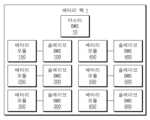
배터리 팩(1)은 배터리 모듈들(150, 250, 350, 450, 550, 650), 슬레이브 BMS들(100, 200, 300, 400, 500, 600) 및 마스터 BMS(10)를 포함할 수 있다. 이하 설명들에서, 배터리 팩(1)은 6개의 배터리 모듈들 및 6개의 슬레이브 BMS들을 포함하는 것으로 가정되지만, 본 발명은 이에 한정되지 않는다.The battery pack (1) may include battery modules (150, 250, 350, 450, 550, 650), slave BMSs (100, 200, 300, 400, 500, 600), and a master BMS (10). In the following descriptions, the battery pack (1) is assumed to include six battery modules and six slave BMSs, but the present invention is not limited thereto.
배터리 모듈들(150, 250, 350, 450, 550, 650) 각각은 직렬 및/또는 병렬 연결된 배터리 셀들을 포함할 수 있다. 배터리 모듈들(150, 250, 350, 450, 550, 650)은 배터리 팩(1)의 외부에 있는 외부 회로들로 전원을 공급할 수 있다.Each of the battery modules (150, 250, 350, 450, 550, 650) may include battery cells connected in series and/or parallel. The battery modules (150, 250, 350, 450, 550, 650) may supply power to external circuits external to the battery pack (1).
슬레이브 BMS들(100, 200, 300, 400, 500, 600)은 각각 배터리 모듈들(150, 250, 350, 450, 550, 650)을 모니터링할 수 있다. 슬레이브 BMS들(100, 200, 300, 400, 500, 600)은 각각 상이한 ID(Identification)들을 가질 수 있다. 슬레이브 BMS들(100, 200, 300, 400, 500, 600)의 ID들은 마스터 BMS(10)에 의해 할당된 것일 수 있으나, 본 발명은 이에 한정되지 않는다. 슬레이브 BMS들(100, 200, 300, 400, 500, 600)은 각자의 ID에 대응하는 시간 구간에서 마스터 BMS(10)와 통신할 수 있다. 이하 설명들에서, 슬레이브 BMS들(100, 200, 300, 400, 500, 600)의 초기 ID들이 변경되지 않는 경우에는, 슬레이브 BMS들(100, 200, 300, 400, 500, 600)이 순차적으로 마스터 BMS(10)와 통신하는 것으로 가정된다. 슬레이브 BMS(600)와 마스터 BMS(10) 간의 통신이 완료된 후에, 다시 슬레이브 BMS(100)부터 마스터 BMS(10)와 통신할 수 있다. 이하 설명들에서, 슬레이브 BMS(300) 및 배터리 모듈(350)의 동작이 자세하게 설명된다. 나머지 슬레이브 BMS들(100, 200, 400, 500, 600)은 슬레이브 BMS(300)와 실질적으로 동일한 동작을 제공하며, 나머지 배터리 모듈들(150, 250, 450, 550, 650)은 배터리 모듈(350)과 실질적으로 동일한 동작을 제공한다.The slave BMSs (100, 200, 300, 400, 500, 600) can monitor the battery modules (150, 250, 350, 450, 550, 650), respectively. The slave BMSs (100, 200, 300, 400, 500, 600) can have different IDs (Identifications). The IDs of the slave BMSs (100, 200, 300, 400, 500, 600) may be assigned by the master BMS (10), but the present invention is not limited thereto. The slave BMSs (100, 200, 300, 400, 500, 600) can communicate with the master BMS (10) in a time section corresponding to their respective IDs. In the following descriptions, if the initial IDs of the slave BMSs (100, 200, 300, 400, 500, 600) do not change, it is assumed that the slave BMSs (100, 200, 300, 400, 500, 600) sequentially communicate with the master BMS (10). After the communication between the slave BMS (600) and the master BMS (10) is completed, communication can be resumed from the slave BMS (100) to the master BMS (10). In the following descriptions, the operations of the slave BMS (300) and the battery module (350) are described in detail. The remaining slave BMSs (100, 200, 400, 500, 600) provide substantially the same operation as the slave BMS (300), and the remaining battery modules (150, 250, 450, 550, 650) provide substantially the same operation as the battery module (350).
슬레이브 BMS(300)는 배터리 모듈(350)에 발생한 에러를 감지할 수 있다. 슬레이브 BMS(300)는 감지된 에러에 관한 정보를 마스터 BMS(10)로 출력할 수 있다. 마스터 BMS(10)는 슬레이브 BMS(300)로부터 제공받는 정보에 기초하여, 배터리 모듈(350)에 적절한 조치를 취할 수 있다. 본 발명의 실시 예에 따르면, 배터리 모듈(350)에 발생한 에러가 치명적인 경우, 마스터 BMS(10)는 배터리 모듈(350)에 빠르게 조치를 취할 수 있다.The slave BMS (300) can detect an error that has occurred in the battery module (350). The slave BMS (300) can output information about the detected error to the master BMS (10). The master BMS (10) can take appropriate action on the battery module (350) based on the information provided from the slave BMS (300). According to an embodiment of the present invention, if an error that has occurred in the battery module (350) is critical, the master BMS (10) can quickly take action on the battery module (350).
슬레이브 BMS(300)는 배터리 모듈(350)에 발생한 에러가 치명적인지 여부를 감지할 수 있다. 이하 설명들에서, "긴급 에러"는 치명적인 에러를 의미한다. "긴급 에러"는 과전압(over voltage), 저전압(under voltage), 과열(over temperature), 과전류(over current) 등을 의미할 수 있다. 이하 설명들에서, "일반 에러"는 치명적이지 않은 에러를 의미한다. "일반 에러"는 배터리 모듈(350)의 SOC(State Of Charge)가 낮거나, 배터리 모듈(350)의 일부 배터리 셀이 동작하지 않는 것을 의미할 수 있다. 다만, 상술한 분류는 예시적인 것으로 이에 한정되는 것은 아니며, 위에서 분류한 것과 상이한 기준으로 에러들을 "긴급 에러" 또는 "일반 에러"로 분류할 수 있을 것이다.The slave BMS (300) can detect whether an error that occurred in the battery module (350) is fatal. In the following descriptions, an "emergency error" means a fatal error. An "emergency error" may mean over voltage, under voltage, over temperature, over current, etc. In the following descriptions, a "general error" means a non-fatal error. A "general error" may mean that the SOC (State Of Charge) of the battery module (350) is low or that some battery cells of the battery module (350) are not operating. However, the above-described classification is exemplary and is not limited thereto, and errors may be classified as "emergency errors" or "general errors" based on criteria different from those classified above.
배터리 모듈(350)에 긴급 에러가 발생한 것으로 판단되는 경우, 슬레이브 BMS(300)는 에러에 대한 정보를 보다 더 빨리 출력하기 위해, 자신의 ID를 변경할 수 있다. 슬레이브 BMS(300)는 자신의 ID를 다른 슬레이브 BMS의 ID로 변경할 수 있다. 이 경우, 다른 슬레이브 BMS의 ID에 대응하는 시간 구간은 에러가 발생한 시각과 슬레이브 BMS(300)의 초기 ID에 대응하는 시간 구간 사이의 시간 구간일 수 있다. 예로서, 슬레이브 BMS(100)가 마스터 BMS(10)와 통신 중에 배터리 모듈(350)에서 긴급 에러가 발생한 경우, 슬레이브 BMS(300)는 자신의 ID를 슬레이브 BMS(100)의 ID 또는 슬레이브 BMS(200)의 ID로 변경할 수 있다. 다른 예로서, 슬레이브 BMS(500)가 마스터 BMS(10)와 통신 중에 배터리 모듈(350)에서 긴급 에러가 발생한 경우, 슬레이브 BMS(300)는 자신의 ID를 슬레이브 BMS들(500, 600, 100, 200) 중 하나의 ID로 변경할 수 있다.If it is determined that an emergency error has occurred in the battery module (350), the slave BMS (300) can change its ID in order to output information about the error more quickly. The slave BMS (300) can change its ID to the ID of another slave BMS. In this case, the time interval corresponding to the ID of another slave BMS may be the time interval between the time at which the error occurred and the time interval corresponding to the initial ID of the slave BMS (300). For example, if an emergency error has occurred in the battery module (350) while the slave BMS (100) is communicating with the master BMS (10), the slave BMS (300) can change its ID to the ID of the slave BMS (100) or the ID of the slave BMS (200). As another example, if an emergency error occurs in the battery module (350) while the slave BMS (500) is communicating with the master BMS (10), the slave BMS (300) can change its ID to the ID of one of the slave BMSs (500, 600, 100, 200).
특히, 슬레이브 BMS(300)는 자신의 ID를 에러가 발생한 당시에 마스터 BMS(10)와 통신 중인 슬레이브 BMS(100)의 ID로 변경할 수 있다. 따라서, 슬레이브 BMS(300)는 에러에 대한 정보를 마스터 BMS(10)로 보다 더 빨리 전송할 수 있다.In particular, the slave BMS (300) can change its ID to the ID of the slave BMS (100) that was communicating with the master BMS (10) at the time when the error occurred. Therefore, the slave BMS (300) can transmit information about the error to the master BMS (10) more quickly.
슬레이브 BMS(300)는 변경된 ID에 대응하는 시간 구간에서, 자신의 ID가 변경되었음을 나타내는 제 1 알림 신호를 마스터 BMS(10)로 출력할 수 있다. 마스터 BMS(10)는 제 1 알림 신호에 기초하여, 나머지 슬레이브 BMS들(100, 200, 400, 500, 600)로 슬레이브 BMS(300)의 ID가 변경되었음을 나타내는 제 2 알림 신호를 출력할 수 있다. 나머지 슬레이브 BMS들(100, 200, 400, 500, 600)은 제 2 알림 신호에 기초하여, 마스터 BMS(10)와의 통신이 원할하게 이루어지도록, 각자의 ID를 변경할 수 있다. 이 때, 나머지 슬레이브 BMS들(100, 200, 400, 500, 600)이 ID를 변경하는 방법은 배터리 팩(1)에 입력된 규칙을 따를 수 있다. 예로서, 규칙은 슬레이브 BMS(300)가 자신의 ID를 슬레이브 BMS(100)의 초기 ID로 변경한 경우, 슬레이브 BMS(100)가 자신의 ID를 슬레이브 BMS(300)의 초기 ID로 변경하는 것일 수 있다. 다른 예로서, 규칙은 슬레이브 BMS(300)가 자신의 ID를 슬레이브 BMS(100)의 초기 ID로 변경한 경우, 슬레이브 BMS(200)가 자신의 ID를 슬레이브 BMS(300)의 초기 ID로 변경하고 슬레이브 BMS(100)가 자신의 ID를 슬레이브 BMS(200)의 초기 ID로 변경하는 것일 수 있다. 다만, 본 발명은 이에 한정되지 않고, 슬레이브 BMS들의 통신 시간 구간들이 서로 겹치지 않도록 조정하기 위한 다양한 규칙이 이용될 수 있다.The slave BMS (300) can output a first notification signal indicating that its ID has been changed to the master BMS (10) in a time section corresponding to the changed ID. Based on the first notification signal, the master BMS (10) can output a second notification signal indicating that the ID of the slave BMS (300) has been changed to the remaining slave BMSs (100, 200, 400, 500, 600). Based on the second notification signal, the remaining slave BMSs (100, 200, 400, 500, 600) can change their respective IDs so that communication with the master BMS (10) can be performed smoothly. At this time, the method by which the remaining slave BMSs (100, 200, 400, 500, 600) change their IDs can follow the rules input into the battery pack (1). For example, the rule may be that if the slave BMS (300) changes its ID to the initial ID of the slave BMS (100), the slave BMS (100) changes its ID to the initial ID of the slave BMS (300). As another example, the rule may be that if the slave BMS (300) changes its ID to the initial ID of the slave BMS (100), the slave BMS (200) changes its ID to the initial ID of the slave BMS (300) and the slave BMS (100) changes its ID to the initial ID of the slave BMS (200). However, the present invention is not limited thereto, and various rules may be used to adjust the communication time intervals of the slave BMSs so that they do not overlap each other.
마스터 BMS(10)는 슬레이브 BMS(300)로부터 긴급 에러에 대한 정보가 수신되는 경우, 배터리 모듈들(150~650) 및 슬레이브 BMS들(100~600)에 적절한 조치를 취할 수 있다.When information about an emergency error is received from the slave BMS (300), the master BMS (10) can take appropriate action on the battery modules (150 to 650) and the slave BMSs (100 to 600).
배터리 모듈(350)에 일반 에러가 발생한 것으로 판단되는 경우, 슬레이브 BMS(300)는 일시적으로 자신의 ID를 마스터 BMS(10)와 통신 중인 슬레이브 BMS의 ID로 변경할 수 있다. 슬레이브 BMS(300)는 자신의 ID를 변경한 후, 일반 에러가 발생하였음을 나타내는 알림 신호를 마스터 BMS(10)로 출력할 수 있다. 알림 신호가 출력되는데 소요되는 시간은 에러에 대한 정보가 출력되는데 소요되는 시간보다 짧을 수 있다. 슬레이브 BMS(300)는 알림 신호를 출력한 후, 자신의 변경된 ID를 다시 초기 ID로 재변경할 수 있다. 따라서, 일반 에러가 발생한 경우에는, 긴급 에러가 발생한 경우와 달리 나머지 슬레이브 BMS들(100, 200, 400, 500, 600)은 자신의 ID를 변경할 필요가 없다. 슬레이브 BMS(300)는 자신의 초기 ID에 대응하는 시간 구간에서, 일반 에러에 대한 정보를 마스터 BMS(10)로 출력할 수 있다.If it is determined that a general error has occurred in the battery module (350), the slave BMS (300) can temporarily change its ID to the ID of the slave BMS communicating with the master BMS (10). After changing its ID, the slave BMS (300) can output a notification signal indicating that a general error has occurred to the master BMS (10). The time required for the notification signal to be output may be shorter than the time required for information about the error to be output. After outputting the notification signal, the slave BMS (300) can change its changed ID back to the initial ID. Therefore, in the case of a general error, unlike in the case of an emergency error, the remaining slave BMSs (100, 200, 400, 500, 600) do not need to change their IDs. The slave BMS (300) can output information about the general error to the master BMS (10) in the time section corresponding to its initial ID.
마스터 BMS(10)는 알림 신호에 기초하여, 배터리 모듈(350)에 일반 에러가 발생하였음을 인지할 수 있다. 마스터 BMS(10)는 슬레이브 BMS(300)로부터 일반 에러에 대한 정보가 수신되는 경우, 배터리 모듈들(150~650) 및 슬레이브 BMS들(100~600)에 적절한 조치를 취할 수 있다. 다만, 마스터 BMS(10)는 일반 에러에 대한 정보가 수신되기 전에도, 필요한 경우에는 배터리 모듈들(150~650) 및 슬레이브 BMS들(100~600)에 적절한 조치를 취할 수 있다.The master BMS (10) can recognize that a general error has occurred in the battery module (350) based on the notification signal. When information about a general error is received from the slave BMS (300), the master BMS (10) can take appropriate measures for the battery modules (150 to 650) and the slave BMSs (100 to 600). However, the master BMS (10) can take appropriate measures for the battery modules (150 to 650) and the slave BMSs (100 to 600) even before information about a general error is received, if necessary.
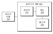
도 2는 도 1의 슬레이브 BMS(300)의 구성을 보여주는 블록도이다.Figure 2 is a block diagram showing the configuration of the slave BMS (300) of Figure 1.
위에서 언급된 것처럼, 나머지 슬레이브 BMS들(100, 200, 400, 500, 600)도 슬레이브 BMS(300)와 실질적으로 동일한 구성을 가지므로, 나머지 슬레이브 BMS들(100, 200, 400, 500, 600)에 대한 설명은 생략된다.As mentioned above, the remaining slave BMSs (100, 200, 400, 500, 600) also have substantially the same configuration as the slave BMS (300), so the description of the remaining slave BMSs (100, 200, 400, 500, 600) is omitted.
슬레이브 BMS(300)는 센싱부(310), MCU(Micro Controller Unit, 320) 및 통신부(330)를 포함할 수 있다.The slave BMS (300) may include a sensing unit (310), an MCU (Micro Controller Unit, 320), and a communication unit (330).
센싱부(310)는 배터리 모듈(350)로부터 배터리 모듈(350)의 상태에 관한 상태 데이터를 획득할 수 있다. 예로서, 센싱부(310)는 배터리 모듈(350)의 전압, 전류, 온도 등을 측정할 수 있다.The sensing unit (310) can obtain status data regarding the status of the battery module (350) from the battery module (350). For example, the sensing unit (310) can measure voltage, current, temperature, etc. of the battery module (350).
MCU(320)는 센싱부(310)로부터 배터리 모듈(350)에 관한 상태 데이터를 수신할 수 있다. MCU(320)는 상태 데이터에 기초하여, 배터리 모듈(350)에 발생한 에러를 감지할 수 있다. MCU(320)는 상태 데이터에 기초하여, 배터리 모듈(350)에 발생한 에러가 긴급 에러인지, 일반 에러인지를 판단할 수 있다. MCU(320)는 배터리 모듈(350)에 발생한 에러의 유형에 따라, 슬레이브 BMS(300)의 ID를 변경하는 시기를 결정할 수 있다. MCU(320)는 변경된 ID에 대응하는 시간 구간에서 통신부(330)가 에러에 대한 정보를 출력할 수 있도록, 통신부(330)를 제어할 수 있다. MCU(320)가 슬레이브 BMS(300)의 ID를 변경하는 방법은 도 3 내지 도 9를 참조하여 자세하게 설명된다.The MCU (320) can receive status data regarding the battery module (350) from the sensing unit (310). The MCU (320) can detect an error occurring in the battery module (350) based on the status data. The MCU (320) can determine whether the error occurring in the battery module (350) is an emergency error or a general error based on the status data. The MCU (320) can determine a time to change the ID of the slave BMS (300) according to the type of error occurring in the battery module (350). The MCU (320) can control the communication unit (330) so that the communication unit (330) can output information about the error in a time section corresponding to the changed ID. The method by which the MCU (320) changes the ID of the slave BMS (300) is described in detail with reference to FIGS. 3 to 9.
통신부(330)는 MCU(320)의 제어에 따라, 슬레이브 BMS(300)의 ID에 대응하는 시간 구간에서 도 1의 마스터 BMS(10)로 에러에 대한 정보를 출력할 수 있다.The communication unit (330) can output information about an error to the master BMS (10) of Fig. 1 in a time section corresponding to the ID of the slave BMS (300) under the control of the MCU (320).
도 1 및 도 2를 참조하여 설명된 것처럼, 본 발명의 슬레이브 BMS(300)는 배터리 모듈에 발생한 에러의 유형에 따라, 자신의 ID를 변경할 수 있다. 슬레이브 BMS(300)는 자신의 ID를 변경함으로써, 초기 ID에 할당된 시간 구간 보다 이전의 시간 구간에서 에러에 대한 정보를 출력할 수 있다. 따라서, 마스터 BMS(10)는 배터리 모듈(350)에 발생한 에러에 대한 정보를 신속하게 전달받을 수 있다.As described with reference to FIGS. 1 and 2, the slave BMS (300) of the present invention can change its ID according to the type of error that has occurred in the battery module. By changing its ID, the slave BMS (300) can output information about an error in a time period earlier than the time period assigned to the initial ID. Accordingly, the master BMS (10) can quickly receive information about an error that has occurred in the battery module (350).
도 3은 도 2의 슬레이브 BMS(300)의 동작을 설명하기 위한 흐름도이다.Figure 3 is a flowchart for explaining the operation of the slave BMS (300) of Figure 2.
S110 동작에서, 슬레이브 BMS(300)는 사용자에 의해 초기화되거나, 마스터 BMS(10)의 제어에 의해 초기화될 수 있다.In operation S110, the slave BMS (300) can be initialized by the user or under the control of the master BMS (10).
S120 동작에서, 초기화된 직후에, 슬레이브 BMS(300)는 일반 모드에서 동작할 수 있다. 슬레이브 BMS(300)는 일반 모드에서 배터리 모듈(350)을 모니터링할 수 있다. 슬레이브 BMS(300)는 배터리 모듈(350)에 대한 상태 데이터를 획득할 수 있다. 일반 모드에서의 슬레이브 BMS(300)의 동작은 도 4를 참조하여 자세하게 설명된다.In the S120 operation, immediately after initialization, the slave BMS (300) can operate in the normal mode. The slave BMS (300) can monitor the battery module (350) in the normal mode. The slave BMS (300) can obtain status data for the battery module (350). The operation of the slave BMS (300) in the normal mode is described in detail with reference to FIG. 4.
S130 동작에서, 슬레이브 BMS(300)는 상태 데이터에 기초하여, 배터리 모듈(350)에 에러가 발생하였는지 여부를 판단할 수 있다.In operation S130, the slave BMS (300) can determine whether an error has occurred in the battery module (350) based on status data.
에러가 발생하지 않은 경우, S120 동작이 다시 수행된다.If no error occurs, operation S120 is performed again.
에러가 발생한 경우, S140 동작이 수행된다. S140 동작에서, 슬레이브 BMS(300)는 배터리 모듈(350)에 발생한 에러를 진단할 수 있다.If an error occurs, operation S140 is performed. In operation S140, the slave BMS (300) can diagnose an error that occurred in the battery module (350).
S150 동작에서, 슬레이브 BMS(300)는 배터리 모듈(350)에 발생한 에러가 치명적인지 여부를 판단할 수 있다.In the S150 operation, the slave BMS (300) can determine whether an error that occurred in the battery module (350) is fatal.
에러가 치명적인 경우, S160 동작이 수행된다. S160 동작에서, 슬레이브 BMS(300)는 동작 모드를 일반 모드로부터 긴급 고장 모드로 전환할 수 있다. 긴급 고장 모드에서 슬레이브 BMS(300)의 동작은 도 5 내지 도 8을 참조하여 자세하게 설명된다.If the error is fatal, operation S160 is performed. In operation S160, the slave BMS (300) can switch the operation mode from the normal mode to the emergency failure mode. The operation of the slave BMS (300) in the emergency failure mode is described in detail with reference to FIGS. 5 to 8.
에러가 치명적이지 않은 경우, S170 동작이 수행된다. S170 동작에서, 슬레이브 BMS(300)는 동작 모드를 일반 모드로부터 일반 고장 모드로 전환할 수 있다. 일반 고장 모드에서 슬레이브 BMS(300)의 동작은 도 9를 참조하여 자세하게 설명된다.If the error is not fatal, operation S170 is performed. In operation S170, the slave BMS (300) can switch the operation mode from the normal mode to the normal failure mode. The operation of the slave BMS (300) in the normal failure mode is described in detail with reference to FIG. 9.
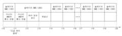
도 4는 일반 모드에서 도 1의 슬레이브 BMS들의 동작을 설명하기 위한 개념도이다.Figure 4 is a conceptual diagram for explaining the operation of the slave BMSs of Figure 1 in normal mode.
도 1을 참조하여 설명된 것처럼, 슬레이브 BMS들(100, 200, 300, 400, 500, 600)은 각자의 ID에 대응하는 시간 구간에서, 마스터 BMS(10)와 통신할 수 있다. 슬레이브 BMS들(100, 200, 300, 400, 500, 600)의 초기 ID들이 변경되지 않는 경우에는, 슬레이브 BMS들(100, 200, 300, 400, 500, 600)이 순차적으로 마스터 BMS(10)와 통신하는 것으로 가정된다. 슬레이브 BMS(300)는 일반 모드에서, ID를 변경하지 않을 수 있다. 따라서, 슬레이브 BMS(300)는 초기 ID에 할당된 시간 구간(t4~t5)에서 마스터 BMS(10)와 통신할 수 있다. 슬레이브 BMS(600)와 마스터 BMS(10) 간의 통신이 완료된 후에, 슬레이브 BMS(100)부터 다시 마스터 BMS(10)와 통신할 수 있다.As described with reference to FIG. 1, the slave BMSs (100, 200, 300, 400, 500, 600) can communicate with the master BMS (10) in the time interval corresponding to their respective IDs. If the initial IDs of the slave BMSs (100, 200, 300, 400, 500, 600) do not change, it is assumed that the slave BMSs (100, 200, 300, 400, 500, 600) sequentially communicate with the master BMS (10). The slave BMS (300) may not change its ID in the normal mode. Therefore, the slave BMS (300) can communicate with the master BMS (10) in the time interval (t4 to t5) assigned to the initial ID. After communication between the slave BMS (600) and the master BMS (10) is completed, communication can be resumed from the slave BMS (100) to the master BMS (10).
이하, 슬레이브 BMS들(100, 200, 300, 400, 500, 600) 각각이 마스터 BMS(10)와 통신하는 방법이 구체적으로 설명된다. 슬레이브 BMS(100)는 시간 구간(t0~t3)에서 마스터 BMS(10)와 통신할 수 있다. 시간 구간(t0~t3)은 준비 구간(t0~t1), 정보 송신 구간(t1~t2) 및 재송신 구간(t2~t3)을 포함할 수 있다.Hereinafter, a method by which each of the slave BMSs (100, 200, 300, 400, 500, 600) communicates with the master BMS (10) is specifically described. The slave BMS (100) can communicate with the master BMS (10) in a time period (t0 to t3). The time period (t0 to t3) can include a preparation period (t0 to t1), an information transmission period (t1 to t2), and a retransmission period (t2 to t3).
준비 구간(t0~t1)은 슬레이브 BMS(100)가 마스터 BMS(10)로 배터리 모듈(150)에 관한 상태 데이터를 출력하기 위해, 마스터 BMS(10)와 통신을 시작하는 구간일 수 있다. 준비 구간(t0~t1)에서, 슬레이브 BMS(100)는 마스터 BMS(10)로 준비 신호를 송신할 수 있다. 마스터 BMS(10)는 준비 신호에 기초하여, 슬레이브 BMS(100)로부터 상태 데이터를 수신하기 위해 준비할 수 있다.The preparation period (t0 to t1) may be a period in which the slave BMS (100) starts communication with the master BMS (10) to output status data regarding the battery module (150) to the master BMS (10). In the preparation period (t0 to t1), the slave BMS (100) may transmit a preparation signal to the master BMS (10). The master BMS (10) may prepare to receive status data from the slave BMS (100) based on the preparation signal.
정보 송신 구간(t1~t2)은 슬레이브 BMS(100)가 마스터 BMS(10)로 배터리 모듈(150)에 관한 상태 데이터를 출력하는 구간일 수 있다. 배터리 모듈(150)에 관한 상태 데이터는 배터리 모듈(150)에 발생한 에러에 관한 데이터를 포함할 수도 있다.The information transmission section (t1 to t2) may be a section in which the slave BMS (100) outputs status data regarding the battery module (150) to the master BMS (10). The status data regarding the battery module (150) may include data regarding an error that occurred in the battery module (150).
재송신 구간(t2~t3)은 슬레이브 BMS(100)가 마스터 BMS(10)로 배터리 모듈(150)에 관한 상태 데이터를 재송신하는 구간일 수 있다. 슬레이브 BMS(100)는 마스터 BMS(10)로 배터리 모듈(150)에 관한 상태 데이터를 보다 더 확실하게 전달하기 위해, 재송신 구간(t2~t3)에서 상태 데이터를 재전송할 수 있다. 다만, 재송신 구간(t2~t3)에서 출력되는 상태 데이터는 정보 송신 구간(t1~t2)에서 출력된 상태 데이터 중 일부 정보들이 생략된 데이터일 수 있다. 즉, 재송신 구간(t2~t3)은 정보 송신 구간(t1~t2) 보다 짧을 수 있다.The retransmission section (t2 to t3) may be a section in which the slave BMS (100) retransmits status data regarding the battery module (150) to the master BMS (10). In order to more reliably transmit the status data regarding the battery module (150) to the master BMS (10), the slave BMS (100) may retransmit the status data in the retransmission section (t2 to t3). However, the status data output in the retransmission section (t2 to t3) may be data in which some information is omitted from the status data output in the information transmission section (t1 to t2). In other words, the retransmission section (t2 to t3) may be shorter than the information transmission section (t1 to t2).
나머지 슬레이브 BMS들(200, 300, 400, 500, 600) 각각도 슬레이브 BMS(100)와 동일한 방법으로 마스터 BMS(10)와 통신할 수 있다. 즉, 도 4에서는 생략되었지만, 나머지 슬레이브 BMS들(200, 300, 400, 500, 600)에 대응하는 시간 구간들 각각도 준비 구간, 정보 송신 구간 및 재송신 구간을 포함할 수 있다.Each of the remaining slave BMSs (200, 300, 400, 500, 600) can also communicate with the master BMS (10) in the same manner as the slave BMS (100). That is, although omitted in FIG. 4, each of the time intervals corresponding to the remaining slave BMSs (200, 300, 400, 500, 600) can also include a preparation interval, an information transmission interval, and a retransmission interval.
도 5는 긴급 고장 모드에서 도 1의 슬레이브 BMS들의 동작들의 일 실시 예를 설명하기 위한 개념도이다.FIG. 5 is a conceptual diagram illustrating one embodiment of the operations of the slave BMSs of FIG. 1 in an emergency failure mode.
도 5를 참조하는 설명에서, 시각 't11'에서, 배터리 모듈(350)에 긴급 에러가 발생한 것으로 가정된다. 시각 't11'은 도 1의 시각 't1'에 대응할 수 있다. 또한, 슬레이브 BMS들(100, 200, 300, 400, 500, 600)의 초기 ID들이 변경되지 않는 경우에는, 슬레이브 BMS들(100, 200, 300, 400, 500, 600)이 순차적으로 마스터 BMS(10)와 통신하는 것으로 가정된다.In the description referring to Fig. 5, it is assumed that an emergency error occurs in the battery module (350) at time 't11'. Time 't11' may correspond to time 't1' of Fig. 1. In addition, if the initial IDs of the slave BMSs (100, 200, 300, 400, 500, 600) are not changed, it is assumed that the slave BMSs (100, 200, 300, 400, 500, 600) sequentially communicate with the master BMS (10).
슬레이브 BMS(300)는 배터리 모듈(350)에 긴급 에러가 발생한 것으로 판단되는 경우, 마스터 BMS(10)로 긴급 에러에 대한 정보를 출력할 수 있다. 이 때, 슬레이브 BMS(300)는 초기 ID에 대응하는 시간 구간(t15~t16) 보다 이전의 시간 구간(t11~t14)에서 긴급 에러에 대한 정보를 출력할 수 있다. 슬레이브 BMS(300)는 시간 구간(t11~t14)에서 긴급 에러에 대한 정보를 출력하기 위해, 자신의 초기 ID를 슬레이브 BMS(100)의 초기 ID로 변경할 수 있다. 슬레이브 BMS(100)는 긴급 에러가 발생한 시각 't11'에서 마스터 BMS(10)와 통신 중인 슬레이브 BMS일 수 있다. 시간 구간(t10~t14)은 슬레이브 BMS(100)의 초기 ID에 대응하는 시간 구간일 수 있으며, 도 4의 시간 구간(t0~t3)에 대응할 수 있다.If the slave BMS (300) determines that an emergency error has occurred in the battery module (350), it can output information about the emergency error to the master BMS (10). At this time, the slave BMS (300) can output information about the emergency error in a time section (t11 to t14) prior to the time section (t15 to t16) corresponding to the initial ID. In order to output information about the emergency error in the time section (t11 to t14), the slave BMS (300) can change its initial ID to the initial ID of the slave BMS (100). The slave BMS (100) may be the slave BMS communicating with the master BMS (10) at the time 't11' when the emergency error occurred. The time interval (t10 to t14) may be a time interval corresponding to the initial ID of the slave BMS (100) and may correspond to the time interval (t0 to t3) of FIG. 4.
슬레이브 BMS(300)는 정보 송신 구간(t12~t13)에서, 긴급 에러에 대한 정보를 마스터 BMS(10)로 출력할 수 있다. 슬레이브 BMS(300)는 정보 송신 구간(t12~t13)에서, 자신의 ID가 슬레이브 BMS(100)의 초기 ID로 변경되었음을 나타내는 제 1 알림 신호를 마스터 BMS(10)로 출력할 수 있다.The slave BMS (300) can output information about an emergency error to the master BMS (10) in the information transmission section (t12 to t13). The slave BMS (300) can output a first notification signal indicating that its ID has been changed to the initial ID of the slave BMS (100) to the master BMS (10) in the information transmission section (t12 to t13).
마스터 BMS(10)는 제 1 알림 신호에 기초하여, 슬레이브 BMS(300)의 ID가 슬레이브 BMS(100)의 초기 ID로 변경되었음을 나타내는 제 2 알림 신호를 나머지 슬레이브 BMS들(100, 200, 400, 500, 600)로 출력할 수 있다. 나머지 슬레이브 BMS들(100, 200, 400, 500, 600)은 제 2 알림 신호에 기초하여, 정해진 규칙대로, 각자의 ID를 변경할 수 있다. 슬레이브 BMS(300)에 의해 슬레이브 BMS(100)가 배터리 모듈(150)에 관한 상태 데이터를 마스터 BMS(10)로 전송하지 못한 경우, 슬레이브 BMS(100)는 슬레이브 BMS(300)와 마스터 BMS(10)간의 통신이 완료된 이후에, 다시 배터리 모듈(150)에 관한 상태 데이터를 마스터 BMS(10)로 출력할 수 있다. 이 경우, 예로서, 슬레이브 BMS(100)는 자신의 ID를 슬레이브 BMS(300)의 초기 ID로 변경할 수 있다. 따라서, 도 5에 도시된 것과 같이, 슬레이브 BMS(300)의 초기 ID에 할당된 시간 구간(t15~t16)에서 슬레이브 BMS(100)는 배터리 모듈(150)에 관한 상태 데이터를 마스터 BMS(10)로 전송할 수 있다. 이 경우, 슬레이브 BMS들(100, 200, 300, 400, 500, 600)이 마스터 BMS(10)와 통신하는 순서는 300->200->100->400->500->600일 수 있다. 다만, 본 발명은 이에 한정되지 않고, 나머지 슬레이브 BMS들(100, 200, 400, 500, 600)은 다양한 방법으로 자신의 ID를 변경하여, 마스터 BMS(10)와 통신하는 순서를 재구성할 수 있다. 다양한 실시 예가 도 6 및 도 7을 참조하여 설명된다.The master BMS (10) can output a second notification signal to the remaining slave BMSs (100, 200, 400, 500, 600) indicating that the ID of the slave BMS (300) has been changed to the initial ID of the slave BMS (100) based on the first notification signal. The remaining slave BMSs (100, 200, 400, 500, 600) can change their IDs according to established rules based on the second notification signal. If the slave BMS (100) fails to transmit status data regarding the battery module (150) to the master BMS (10) by the slave BMS (300), the slave BMS (100) can output status data regarding the battery module (150) to the master BMS (10) again after communication between the slave BMS (300) and the master BMS (10) is completed. In this case, for example, the slave BMS (100) can change its ID to the initial ID of the slave BMS (300). Accordingly, as illustrated in FIG. 5, the slave BMS (100) can transmit status data regarding the battery module (150) to the master BMS (10) in the time period (t15 to t16) assigned to the initial ID of the slave BMS (300). In this case, the order in which the slave BMSs (100, 200, 300, 400, 500, 600) communicate with the master BMS (10) may be 300->200->100->400->500->600. However, the present invention is not limited thereto, and the remaining slave BMSs (100, 200, 400, 500, 600) may change their IDs in various ways to reconstruct the order in which they communicate with the master BMS (10). Various embodiments are described with reference to FIGS. 6 and 7.
도 6은 긴급 고장 모드에서 도 1의 슬레이브 BMS들의 동작들의 다른 실시 예를 설명하기 위한 개념도이다. 설명의 편의를 위해 도 5가 함께 참조된다.Fig. 6 is a conceptual diagram illustrating another embodiment of the operations of the slave BMSs of Fig. 1 in an emergency failure mode. For convenience of explanation, Fig. 5 is also referred to.
도 6에 표시된 시각들(t10~t19)은 도 5에 표시된 시각들(t10~t19)과 대응한다. 도 6을 참조하여서는 나머지 슬레이브 BMS들(100, 200, 400, 500, 600)이 도 5를 참조하여 설명된 방법과 상이한 방법으로, 각각의 ID를 변경하는 방법이 설명되며, 중복되는 설명은 생략된다.The times (t10 to t19) shown in Fig. 6 correspond to the times (t10 to t19) shown in Fig. 5. Referring to Fig. 6, a method of changing each ID of the remaining slave BMSs (100, 200, 400, 500, 600) in a different manner from the method described with reference to Fig. 5 is described, and redundant descriptions are omitted.
긴급 에러가 발생한 슬레이브 BMS(300)의 ID 변경에 따라, 나머지 슬레이브 BMS들(100, 200, 400, 500, 600)은 본래 슬레이브 BMS들(100, 200, 400, 500, 600)과 마스터 BMS(10)가 통신하는 순서가 변경되지 않도록 각각의 ID를 변경할 수 있다. 이 경우, 슬레이브 BMS들(100, 200, 300, 400, 500, 600)이 마스터 BMS(10)와 통신하는 순서는 300->100->200->400->500->600일 수 있다.According to the change of the ID of the slave BMS (300) in which an emergency error occurred, the remaining slave BMSs (100, 200, 400, 500, 600) can change their respective IDs so that the order in which the slave BMSs (100, 200, 400, 500, 600) communicate with the master BMS (10) does not change. In this case, the order in which the slave BMSs (100, 200, 300, 400, 500, 600) communicate with the master BMS (10) can be 300->100->200->400->500->600.
실시 예로서, 나머지 슬레이브 BMS들(100, 200, 400, 500, 600) 중 슬레이브 BMS(200)가 ID를 변경하는 방법이 설명된다. 슬레이브 BMS(200)는 자신의 ID를 슬레이브 BMS(300)의 초기 ID로 변경할 수 있다. 슬레이브 BMS(300)의 초기 ID가 대응하는 시간 구간(도 5의 t15~t16)은 슬레이브 BMS(200)의 초기 ID가 대응하는 시간 구간(도 5의 t14~t15) 직후의 시간 구간일 수 있다.As an example, a method for changing an ID of a slave BMS (200) among the remaining slave BMSs (100, 200, 400, 500, 600) is described. The slave BMS (200) can change its ID to the initial ID of the slave BMS (300). The time interval (t15 to t16 in FIG. 5) to which the initial ID of the slave BMS (300) corresponds may be a time interval immediately following the time interval (t14 to t15 in FIG. 5) to which the initial ID of the slave BMS (200) corresponds.
도 7은 긴급 고장 모드에서 도 1의 슬레이브 BMS들의 동작들의 다른 실시 예를 설명하기 위한 개념도이다. 설명의 편의를 위해 도 5가 함께 참조된다.Fig. 7 is a conceptual diagram illustrating another embodiment of the operations of the slave BMSs of Fig. 1 in an emergency failure mode. For convenience of explanation, Fig. 5 is also referred to.
도 7에 표시된 시각들(t10~t19)은 도 5에 표시된 시각들(t10~t19)과 대응한다. 도 7을 참조하여서는 나머지 슬레이브 BMS들(100, 200, 400, 500, 600)이 한 사이클이 완료된 이후(즉, 시각 't18'이후), 자신의 ID를 초기 ID로 변경하는 방법이 설명된다.The times (t10 to t19) shown in Fig. 7 correspond to the times (t10 to t19) shown in Fig. 5. Referring to Fig. 7, a method is described in which the remaining slave BMSs (100, 200, 400, 500, 600) change their IDs to the initial IDs after one cycle is completed (i.e., after time 't18').
이 경우, 슬레이브 BMS들(100, 200, 400, 500, 600)은 긴급 에러가 발생한 사이클(t10~t18)에서는, 도 5를 참조하여 설명된 방법과 동일한 방법으로, 각각의 ID를 변경할 수 있다. 다만, 본 발명은 이에 한정되지 않고, 슬레이브 BMS들(100, 200, 400, 500, 600)은 긴급 에러가 발생한 사이클(t10~t18)에서, 도 6을 참조하여 설명된 방법과 동일한 방법으로, 각각의 ID를 변경할 수도 있다. 슬레이브 BMS들(100, 200, 300, 400, 500, 600)은 긴급 에러가 발생한 사이클(t10~t18)이 완료되면, 자신의 ID를 초기 ID로 변경할 수 있다. 이 경우, 슬레이브 BMS들(100, 200, 300, 400, 500, 600)이 마스터 BMS(10)와 통신하는 순서는 100->200->300->400->500->600일 수 있다.In this case, the slave BMSs (100, 200, 400, 500, 600) can change their respective IDs in the cycle (t10 to t18) in which an emergency error occurs, in the same manner as described with reference to FIG. 5. However, the present invention is not limited thereto, and the slave BMSs (100, 200, 400, 500, 600) can also change their respective IDs in the cycle (t10 to t18) in which an emergency error occurs, in the same manner as described with reference to FIG. 6. The slave BMSs (100, 200, 300, 400, 500, 600) can change their IDs to the initial IDs when the cycle (t10 to t18) in which an emergency error occurs is completed. In this case, the order in which the slave BMSs (100, 200, 300, 400, 500, 600) communicate with the master BMS (10) may be 100->200->300->400->500->600.
도 8은 긴급 고장 모드에서 도 1의 슬레이브 BMS들의 동작들의 다른 실시 예를 설명하기 위한 개념도이다.FIG. 8 is a conceptual diagram illustrating another embodiment of the operations of the slave BMSs of FIG. 1 in an emergency failure mode.
도 8을 참조하는 설명에서, 시각 't22'에, 배터리 모듈(350)에 긴급 에러가 발생한 것으로 가정된다. 시각 't22'는 도 1의 시각 't2'에 대응할 수 있다. 또한, 슬레이브 BMS들(100, 200, 300, 400, 500, 600)의 초기 ID들이 변경되지 않는 경우에는, 슬레이브 BMS들(100, 200, 300, 400, 500, 600)이 순차적으로 마스터 BMS(10)와 통신하는 것으로 가정된다. 도 8은 도 5를 참조하여 설명된 방법과의 차이점 위주로 설명된다.In the description referring to Fig. 8, it is assumed that an emergency error occurs in the battery module (350) at time 't22'. Time 't22' may correspond to time 't2' of Fig. 1. In addition, if the initial IDs of the slave BMSs (100, 200, 300, 400, 500, 600) are not changed, it is assumed that the slave BMSs (100, 200, 300, 400, 500, 600) sequentially communicate with the master BMS (10). Fig. 8 is described mainly with respect to the differences from the method described with reference to Fig. 5.
도 5에서와 달리, 도 8에서는 슬레이브 BMS(300)에 의해 마스터 BMS(10)와의 통신이 중단되기 이전에, 슬레이브 BMS(100)가 배터리 모듈(150)에 관한 상태 데이터를 마스터 BMS(10)로 1회 전송할 수 있다. 이 경우, 슬레이브 BMS(100)는 슬레이브 BMS(300)의 정보 전송이 완료된 이후에 배터리 모듈(150)에 관한 상태 데이터를 마스터 BMS(10)로 재전송하지 않을 수 있다. 즉, 슬레이브 BMS(100)는 자신의 ID를 슬레이브 BMS(300)의 초기 ID로 변경하지 않을 수 있다.Unlike in FIG. 5, in FIG. 8, before communication with the master BMS (10) is interrupted by the slave BMS (300), the slave BMS (100) may transmit status data regarding the battery module (150) to the master BMS (10) once. In this case, the slave BMS (100) may not retransmit status data regarding the battery module (150) to the master BMS (10) after the slave BMS (300) completes transmitting information. That is, the slave BMS (100) may not change its ID to the initial ID of the slave BMS (300).
도 9은 일반 고장 모드에서 도 1의 슬레이브 BMS들의 동작들의 일 실시 예를 설명하기 위한 개념도이다.FIG. 9 is a conceptual diagram illustrating one embodiment of the operations of the slave BMSs of FIG. 1 in a normal failure mode.
도 9을 참조하는 설명에서, 시각 't31'에서, 배터리 모듈(350)에 일반 에러가 발생한 것으로 가정된다. 시각 't31'은 도 1의 시각 't1'에 대응할 수 있다. 또한, 슬레이브 BMS들(100, 200, 300, 400, 500, 600)의 초기 ID들이 변경되지 않는 경우에는, 슬레이브 BMS들(100, 200, 300, 400, 500, 600)이 순차적으로 마스터 BMS(10)와 통신하는 것으로 가정된다. 도 8은 도 5에 도시된 상황과의 차이점 위주로 설명된다.In the description referring to Fig. 9, it is assumed that a general error occurs in the battery module (350) at time 't31'. Time 't31' may correspond to time 't1' of Fig. 1. In addition, if the initial IDs of the slave BMSs (100, 200, 300, 400, 500, 600) are not changed, it is assumed that the slave BMSs (100, 200, 300, 400, 500, 600) sequentially communicate with the master BMS (10). Fig. 8 is explained mainly with respect to the differences from the situation illustrated in Fig. 5.
슬레이브 BMS(300)는 배터리 모듈(350)에 일반 에러가 발생한 것으로 판단되는 경우, 마스터 BMS(10)로 배터리 모듈(350)에 에러가 발생하였음을 알리기 위한 알림 신호를 출력할 수 있다. 다만, 슬레이브 BMS(300)는 긴급 고장 모드에서와 달리, 마스터 BMS(10)와 통신 중인 슬레이브 BMS(100)로부터 배터리 모듈(150)에 관한 상태 데이터가 1회 출력된 이후에, 알림 신호를 송신할 수 있다. 알림 신호는 시간 구간(t32~t33)에서 출력될 수 있으며, 시간 구간(t32~t33)은 도 1의 시간 구간(t2~t3)에 대응할 수 있다. 알림 신호가 출력되기 위해 필요한 시간 구간(t32~t33)은 도 5의 시간 구간(t11~t14) 보다 짧을 수 있다. 시간 구간(t11~t14)은 에러에 대한 정보가 출력되기 위해 필요한 시간 구간일 수 있다.If it is determined that a general error has occurred in the battery module (350), the slave BMS (300) can output a notification signal to notify the master BMS (10) that an error has occurred in the battery module (350). However, unlike in the emergency failure mode, the slave BMS (300) can transmit the notification signal after status data regarding the battery module (150) is output once from the slave BMS (100) communicating with the master BMS (10). The notification signal can be output in the time interval (t32 to t33), and the time interval (t32 to t33) can correspond to the time interval (t2 to t3) of FIG. 1. The time interval (t32 to t33) required for the notification signal to be output can be shorter than the time interval (t11 to t14) of FIG. 5. The time interval (t11 to t14) can be a time interval required for information about the error to be output.
슬레이브 BMS(300)는 슬레이브 BMS(100)로부터 배터리 모듈(150)에 관한 상태 데이터가 1회 출력된 이후(즉, 시각 't32'이후), 자신의 ID를 슬레이브 BMS(100)의 초기 ID로 변경할 수 있다. 슬레이브 BMS(300)는 알림 신호를 출력한 이후(즉, 시각 't33'이후), 자신의 변경된 ID를 다시 초기 ID로 변경할 수 있다. 슬레이브 BMS(300)는 자신의 초기 ID에 대응하는 시간 구간(t34~t35)에서, 일반 에러에 대한 정보를 마스터 BMS(10)로 출력할 수 있다. 시간 구간(t34~t35)은 도 4의 시간 구간(t4~t5)에 대응할 수 있다. 또한, 일반 고장 모드에서 슬레이브 BMS(300)는 자신의 ID를 일시적으로 변경하므로, 나머지 슬레이브 BMS들(100, 200, 400, 500, 600)은 자신의 ID를 변경하지 않을 수 있다.The slave BMS (300) can change its ID to the initial ID of the slave BMS (100) after the status data on the battery module (150) is output once from the slave BMS (100) (i.e., after time 't32'). The slave BMS (300) can change its changed ID back to the initial ID after outputting a notification signal (i.e., after time 't33'). The slave BMS (300) can output information on a general error to the master BMS (10) in a time section (t34 to t35) corresponding to its initial ID. The time section (t34 to t35) can correspond to the time section (t4 to t5) of FIG. 4. Additionally, in normal failure mode, the slave BMS (300) temporarily changes its ID, so the remaining slave BMSs (100, 200, 400, 500, 600) may not change their IDs.
도 10은 본 발명의 일 실시 예에 따른 BMS의 하드웨어 구성을 나타내는 도면이다.FIG. 10 is a diagram showing the hardware configuration of a BMS according to one embodiment of the present invention.
도 10을 참조하면, BMS(1000)는, 각종 처리 및 각 구성을 제어하는 마이크로컨트롤러(MCU; 810)와, 운영체제 프로그램 및 각종 프로그램(예로서, 배터리 진단 프로그램, 전압 근사식 산출 프로그램 등) 등이 기록되는 메모리(1020)와, 배터리 셀 모듈 및/또는 반도체 스위칭 소자와의 사이에서 입력 인터페이스 및 출력 인터페이스를 제공하는 입출력 인터페이스(1030)와, 유무선 통신망을 통해 외부와 통신 가능한 통신 인터페이스(1040)를 구비할 수 있다. 이와 같이, 본 발명에 따른 컴퓨터 프로그램은 메모리(1020)에 기록되고, 마이크로 컨트롤러(1010)에 의해 처리됨으로써 예를 들면 도 2에서 도시한 각 기능 블록들을 수행하는 모듈로서 구현될 수 있다.Referring to FIG. 10, the BMS (1000) may be equipped with a microcontroller (MCU; 810) that controls various processes and each configuration, a memory (1020) in which an operating system program and various programs (e.g., a battery diagnosis program, a voltage approximation calculation program, etc.) are recorded, an input/output interface (1030) that provides an input interface and an output interface between a battery cell module and/or a semiconductor switching element, and a communication interface (1040) that can communicate with the outside via a wired/wireless communication network. In this way, a computer program according to the present invention may be recorded in the memory (1020) and processed by the microcontroller (1010), thereby being implemented as a module that performs each functional block illustrated in FIG. 2, for example.
상술된 내용은 본 발명을 실시하기 위한 구체적인 실시 예들이다. 본 발명은 상술된 실시 예들뿐만 아니라, 단순하게 설계 변경되거나 용이하게 변경할 수 있는 실시 예들 또한 포함할 것이다. 또한, 본 발명은 실시 예들을 이용하여 용이하게 변형하여 실시할 수 있는 기술들도 포함될 것이다. 따라서, 본 발명의 범위는 상술된 실시 예들에 국한되어 정해져서는 안되며 후술하는 특허청구범위뿐만 아니라 이 발명의 특허청구범위와 균등한 것들에 의해 정해져야 할 것이다.The above-described contents are specific embodiments for carrying out the present invention. The present invention will include not only the above-described embodiments, but also embodiments that can be simply designed or easily changed. In addition, the present invention will also include technologies that can be easily modified and implemented using the embodiments. Therefore, the scope of the present invention should not be limited to the above-described embodiments, but should be determined by the claims described below as well as the equivalents of the claims of this invention.
Claims (15)
Translated fromKorean제 1 배터리 모듈에 에러가 발생한 경우, 상기 에러의 유형을 긴급 에러 또는 일반 에러로 분류하는 제 1 슬레이브 BMS를 포함하되,
상기 제 1 슬레이브 BMS는 상기 제 1 슬레이브 BMS의 ID(Identification)에 대응하는 시간 구간에서 상기 마스터 BMS와 통신하고, 상기 에러의 유형에 기초하여 상이한 방식으로 상기 ID를 변경하고, 상기 변경된 ID에 대응하는 시간 구간에서 상기 에러에 대한 정보를 상기 마스터 BMS로 출력하는 배터리 팩.Master BMS; and
In case an error occurs in the first battery module, the first slave BMS is included to classify the type of the error as an emergency error or a general error.
A battery pack in which the first slave BMS communicates with the master BMS in a time interval corresponding to an ID (Identification) of the first slave BMS, changes the ID in a different manner based on the type of the error, and outputs information about the error to the master BMS in a time interval corresponding to the changed ID.
제 2 배터리 모듈을 모니터링하는 제 2 슬레이브 BMS를 더 포함하고,
상기 제 1 슬레이브 BMS는 상기 에러의 유형이 상기 긴급 에러인 경우, 상기 ID를 제 1 ID로부터 상기 제 2 슬레이브 BMS의 제 2 ID로 변경하고,
상기 제 1 ID에 대응하는 제 1 시간 구간은 상기 제 2 ID에 대응하는 제 2 시간 구간 이후의 시간 구간이고,
상기 제 2 시간 구간은 상기 에러가 발생한 시각 이후의 시간 구간인 배터리 팩.In claim 1,
Further comprising a second slave BMS for monitoring the second battery module,
The first slave BMS changes the ID from the first ID to the second ID of the second slave BMS when the type of the error is the emergency error,
The first time interval corresponding to the first ID is a time interval after the second time interval corresponding to the second ID,
The above second time interval is the battery pack time interval after the time at which the above error occurred.
상기 에러가 발생한 상기 시각에서, 상기 제 2 슬레이브 BMS는 상기 마스터 BMS와 통신 중인 슬레이브 BMS인 배터리 팩.In claim 2,
At the time when the above error occurred, the second slave BMS is a battery pack that is a slave BMS communicating with the master BMS.
상기 마스터 BMS는 상기 제 1 슬레이브 BMS의 상기 ID가 변경된 경우, 상기 제 2 슬레이브 BMS로 알림 신호를 출력하고,
상기 제 2 슬레이브 BMS는 상기 알림 신호에 기초하여, 상기 제 2 슬레이브 BMS의 ID를 변경하는 배터리 팩.In claim 2,
The above master BMS outputs a notification signal to the second slave BMS when the ID of the first slave BMS is changed,
The second slave BMS is a battery pack that changes the ID of the second slave BMS based on the notification signal.
상기 제 2 슬레이브 BMS는 상기 알림 신호에 기초하여, 상기 제 2 슬레이브 BMS의 상기 ID를 상기 제 2 ID로부터 상기 제 1 ID로 변경하는 배터리 팩.In claim 4,
A battery pack wherein the second slave BMS changes the ID of the second slave BMS from the second ID to the first ID based on the notification signal.
상기 제 2 슬레이브 BMS는 상기 제 1 시간 구간에서 상기 마스터 BMS와 통신한 후, 상기 제 2 슬레이브 BMS의 상기 ID를 상기 제 1 ID로부터 상기 제 2 ID로 재변경하고,
상기 제 1 슬레이브 BMS는 상기 제 1 시간 구간에서 상기 제 2 슬레이브 BMS와 상기 마스터 BMS 간의 통신이 완료된 이후, 상기 제 1 슬레이브 BMS의 상기 ID를 상기 제 2 ID로부터 상기 제 1 ID로 재변경하는 배터리 팩.In claim 5,
The second slave BMS, after communicating with the master BMS during the first time period, changes the ID of the second slave BMS from the first ID to the second ID,
A battery pack wherein the first slave BMS changes the ID of the first slave BMS from the second ID to the first ID after communication between the second slave BMS and the master BMS is completed in the first time period.
상기 제 2 슬레이브 BMS는 상기 제 1 시간 구간에서 상기 마스터 BMS와 통신한 후, 상기 제 2 슬레이브 BMS의 상기 ID를 상기 제 1 ID로 유지하고,
상기 제 1 슬레이브 BMS는 상기 제 1 슬레이브 BMS의 상기 ID를 상기 제 2 ID로 유지하는 배터리 팩.In claim 5,
The second slave BMS maintains the ID of the second slave BMS as the first ID after communicating with the master BMS during the first time period,
The above first slave BMS is a battery pack that maintains the ID of the above first slave BMS as the second ID.
상기 제 2 슬레이브 BMS는
상태 정보 송신 구간에서 상기 제 2 배터리 모듈에 관한 상태 정보를 상기 마스터 BMS로 전송하고, 상기 상태 정보 송신 구간 이후의 재전송 구간에서 상기 상태 정보를 상기 마스터 BMS로 재전송하고,
상기 상태 정보 송신 구간에서 상기 제 1 슬레이브 BMS에 의해 상기 마스터 BMS와의 통신이 중단된 경우, 상기 에러에 대한 상기 정보가 상기 마스터 BMS로 전송된 이후에 상기 상태 정보를 상기 마스터 BMS로 전송하고,
상기 재전송 구간에서 상기 제 1 슬레이브 BMS에 의해 상기 마스터 BMS와의 통신이 중단된 경우, 상기 에러에 대한 상기 정보가 상기 마스터 BMS로 전송된 이후에 상기 상태 정보를 상기 마스터 BMS로 전송하지 않는 배터리 팩.In claim 4,
The above second slave BMS
In the status information transmission section, status information about the second battery module is transmitted to the master BMS, and in the retransmission section after the status information transmission section, the status information is retransmitted to the master BMS.
If communication with the master BMS is interrupted by the first slave BMS during the above status information transmission section, the status information is transmitted to the master BMS after the information about the error is transmitted to the master BMS,
A battery pack that does not transmit the status information to the master BMS after the information about the error is transmitted to the master BMS when communication with the master BMS is interrupted by the first slave BMS during the retransmission section.
상기 마스터 BMS는 상기 제 1 슬레이브 BMS의 상기 ID가 변경된 경우, 상기 긴급 에러가 발생된 상기 시각과 상기 제 1 시간 구간 사이에 있는 시간 구간들에 대응하는 ID들을 갖는 슬레이브 BMS들로 알림 신호를 출력하고,
상기 슬레이브 BMS들은 상기 알림 신호에 기초하여, 상기 슬레이브 BMS들 각각의 ID를 변경하는 배터리 팩.In claim 2,
The above master BMS outputs a notification signal to slave BMSs having IDs corresponding to time intervals between the time at which the emergency error occurred and the first time interval when the ID of the first slave BMS is changed,
A battery pack in which the slave BMSs change the ID of each of the slave BMSs based on the notification signal.
상기 슬레이브 BMS들 중 임의의 슬레이브 BMS는 상기 알림 신호에 기초하여 상기 임의의 슬레이브 BMS의 ID를 제 3 ID로부터 제 4 ID로 변경하고,
상기 제 4 ID에 대응하는 시간 구간은 상기 제 3 ID에 대응하는 시간 구간 직후의 시간 구간인 배터리 팩.In claim 9,
Any slave BMS among the above slave BMSs changes the ID of the above slave BMS from the third ID to the fourth ID based on the above notification signal,
A battery pack in which the time interval corresponding to the above 4th ID is the time interval immediately following the time interval corresponding to the above 3rd ID.
제 2 배터리 모듈을 모니터링하는 제 2 슬레이브 BMS를 더 포함하고,
상기 제 1 슬레이브 BMS는 상기 에러의 유형이 상기 일반 에러인 경우, 상기 마스터 BMS와 통신 중인 상기 제 2 슬레이브 BMS로부터 상기 제 2 배터리 모듈에 관한 상태 데이터가 출력된 이후에, 상기 제 1 슬레이브 BMS의 상기 ID를 제 1 ID로부터 상기 제 2 슬레이브 BMS의 제 2 ID로 변경하고,
상기 제 1 ID에 대응하는 제 1 시간 구간은 상기 제 2 ID에 대응하는 제 2 시간 구간 이후의 시간 구간이고,
상기 제 2 시간 구간은 상기 에러가 발생한 시각 이후의 시간 구간인 배터리 팩.In claim 1,
Further comprising a second slave BMS for monitoring the second battery module,
The first slave BMS changes the ID of the first slave BMS from the first ID to the second ID of the second slave BMS after the status data regarding the second battery module is output from the second slave BMS communicating with the master BMS when the type of the error is the general error.
The first time interval corresponding to the first ID is a time interval after the second time interval corresponding to the second ID,
The above second time interval is the battery pack time interval after the time at which the above error occurred.
상기 제 1 슬레이브 BMS는 상기 제 2 슬레이브 BMS가 상기 제 2 배터리 모듈에 관한 상기 상태 데이터를 재전송하기 위한 재전송 구간에서, 상기 에러가 발생하였음을 나타내는 알림 신호를 출력하고, 상기 알림 신호를 출력한 후 상기 ID를 상기 제 2 ID로부터 상기 제 1 ID로 재변경하고, 상기 제 1 시간 구간에서 상기 에러에 대한 상기 정보를 출력하되,
상기 재전송 구간은 상기 제 2 시간 구간 내의 시간 구간인 배터리 팩.In claim 11,
The first slave BMS outputs a notification signal indicating that the error has occurred during a retransmission period for the second slave BMS to retransmit the status data regarding the second battery module, and after outputting the notification signal, changes the ID from the second ID to the first ID, and outputs the information about the error during the first time period.
The above retransmission interval is a battery pack that is a time interval within the second time interval.
상기 제 1 슬레이브 BMS의 ID(Identification)에 대응하는 시간 구간에서 상기 마스터 BMS와 통신하는 통신부; 및
배터리 모듈에 에러가 발생한 경우 상기 에러의 유형을 긴급 에러 또는 일반 에러로 판단하고, 상기 에러의 유형이 상기 긴급 에러인 것으로 판단되는 경우 상기 ID를 제 1 ID로부터 제 2 ID로 변경하는 제어부를 포함하되,
상기 제 1 ID에 대응하는 제 1 시간 구간은 상기 제 2 ID에 대응하는 제 2 시간 구간 이후의 시간 구간이고,
상기 제 2 시간 구간은 상기 에러가 발생한 시각 이후의 시간 구간이고,
상기 통신부는 상기 ID가 상기 제 2 ID로 변경되는 경우, 상기 제 2 시간 구간에서 상기 마스터 BMS로 상기 에러에 대한 정보를 출력하는 제 1 슬레이브 BMS.For the first slave BMS communicating with the master BMS,
A communication unit that communicates with the master BMS in a time period corresponding to the ID (Identification) of the first slave BMS; and
Including a control unit that determines the type of the error as an emergency error or a general error when an error occurs in the battery module, and changes the ID from the first ID to the second ID when the type of the error is determined to be the emergency error.
The first time interval corresponding to the first ID is a time interval after the second time interval corresponding to the second ID,
The above second time interval is the time interval after the time at which the above error occurred,
The above communication unit is a first slave BMS that outputs information about the error to the master BMS in the second time interval when the ID is changed to the second ID.
상기 제 2 ID는 상기 에러가 발생한 상기 시각에서 상기 마스터 BMS와 통신 중인 제 2 슬레이브 BMS의 ID인 제 1 슬레이브 BMS.In claim 13,
The above second ID is the ID of the first slave BMS which is communicating with the master BMS at the time when the above error occurred.
상기 제어부는 상기 에러의 유형이 상기 일반 에러인 것으로 판단되는 경우, 상기 ID를 상기 제 1 ID로부터 상기 제 2 ID로 변경하여 상기 제 2 시간 구간에서 상기 일반 에러가 발생하였음을 나타내는 알림 신호를 출력하고, 상기 알림 신호를 출력한 후 상기 ID를 상기 제 2 ID로부터 상기 제 1 ID로 재변경하고, 상기 제 1 시간 구간에서 상기 에러에 대한 상기 정보를 출력하는 제 1 슬레이브 BMS.
In claim 13,
A first slave BMS which, when the control unit determines that the type of the error is the general error, changes the ID from the first ID to the second ID and outputs a notification signal indicating that the general error has occurred in the second time interval, and after outputting the notification signal, changes the ID from the second ID back to the first ID and outputs the information about the error in the first time interval.
Priority Applications (9)
| Application Number | Priority Date | Filing Date | Title |
|---|---|---|---|
| KR1020200074768AKR102818312B1 (en) | 2020-06-19 | 2020-06-19 | Slave battery monitoring system diagnosing error of battery module and battery pack including the slave battery monitoring system |
| ES21826797TES2987943T3 (en) | 2020-06-19 | 2021-05-28 | SLAVE BMS FOR DIAGNOSTICS OF A BATTERY MODULE AND A BATTERY PACK COMPRISING THE SAME SLAVE BMS |
| JP2022548534AJP7355297B2 (en) | 2020-06-19 | 2021-05-28 | A slave BMS for diagnosing an error in a battery module and a battery pack including the slave BMS |
| PL21826797.9TPL4095977T3 (en) | 2020-06-19 | 2021-05-28 | Slave bms for diagnosing an error of a battery module and battery pack comprising same slave bms |
| HUE21826797AHUE066585T2 (en) | 2020-06-19 | 2021-05-28 | Slave bms for diagnosing an error of a battery module and battery pack comprising same slave bms |
| PCT/KR2021/006645WO2021256722A1 (en) | 2020-06-19 | 2021-05-28 | Slave bms for diagnosing error of battery module and battery pack including slave bms |
| EP21826797.9AEP4095977B1 (en) | 2020-06-19 | 2021-05-28 | Slave bms for diagnosing an error of a battery module and battery pack comprising same slave bms |
| CN202180016475.8ACN115176373B (en) | 2020-06-19 | 2021-05-28 | Slave BMS for diagnosing battery module errors and battery pack including the slave BMS |
| US17/801,924US12416683B2 (en) | 2020-06-19 | 2021-05-28 | Slave BMS for diagnosing an error of a battery module and battery pack comprising same slave BMS |
Applications Claiming Priority (1)
| Application Number | Priority Date | Filing Date | Title |
|---|---|---|---|
| KR1020200074768AKR102818312B1 (en) | 2020-06-19 | 2020-06-19 | Slave battery monitoring system diagnosing error of battery module and battery pack including the slave battery monitoring system |
Publications (2)
| Publication Number | Publication Date |
|---|---|
| KR20210157017A KR20210157017A (en) | 2021-12-28 |
| KR102818312B1true KR102818312B1 (en) | 2025-06-10 |
Family
ID=79178189
Family Applications (1)
| Application Number | Title | Priority Date | Filing Date |
|---|---|---|---|
| KR1020200074768AActiveKR102818312B1 (en) | 2020-06-19 | 2020-06-19 | Slave battery monitoring system diagnosing error of battery module and battery pack including the slave battery monitoring system |
Country Status (9)
| Country | Link |
|---|---|
| US (1) | US12416683B2 (en) |
| EP (1) | EP4095977B1 (en) |
| JP (1) | JP7355297B2 (en) |
| KR (1) | KR102818312B1 (en) |
| CN (1) | CN115176373B (en) |
| ES (1) | ES2987943T3 (en) |
| HU (1) | HUE066585T2 (en) |
| PL (1) | PL4095977T3 (en) |
| WO (1) | WO2021256722A1 (en) |
Families Citing this family (3)
| Publication number | Priority date | Publication date | Assignee | Title |
|---|---|---|---|---|
| JP7619211B2 (en)* | 2021-08-30 | 2025-01-22 | 株式会社デンソー | Battery Management System |
| KR102845827B1 (en)* | 2021-12-22 | 2025-08-12 | 주식회사 엘지에너지솔루션 | Battery apparatus, battery management system and diagnosis method |
| CN120283364A (en)* | 2023-11-06 | 2025-07-08 | 株式会社Lg新能源 | Battery system, battery pack embedded with the battery system, and battery pack monitoring method using the battery system |
Family Cites Families (20)
| Publication number | Priority date | Publication date | Assignee | Title |
|---|---|---|---|---|
| JP2733242B2 (en)* | 1988-03-28 | 1998-03-30 | 松下電工株式会社 | Time division multiplex transmission method |
| JP2002269661A (en) | 2001-03-08 | 2002-09-20 | Osaka Gas Co Ltd | Abnormality informing system for fuel cell system for domestic use |
| JP5331450B2 (en)* | 2008-11-07 | 2013-10-30 | 株式会社日立製作所 | Power storage module, power storage device, electric motor drive system, and vehicle |
| BR112013010923B1 (en)* | 2010-11-02 | 2020-04-28 | Navitas Solutions Inc | wireless battery area network for an intelligent battery management system |
| JP5421942B2 (en) | 2011-03-02 | 2014-02-19 | 三菱電機株式会社 | Power storage management device |
| KR101539689B1 (en) | 2012-02-20 | 2015-07-27 | 주식회사 엘지화학 | System and method for identifier allowcation of multi-bms |
| KR101926196B1 (en) | 2012-07-09 | 2018-12-06 | 에스케이이노베이션 주식회사 | Fault management apparatus of the parallel battery system and method thereof |
| JP5693547B2 (en) | 2012-11-20 | 2015-04-01 | 三菱重工業株式会社 | Battery management apparatus, control method and program thereof, and battery monitoring system including the same |
| KR101454518B1 (en)* | 2012-12-26 | 2014-10-24 | 넥스콘 테크놀러지 주식회사 | Using the electric switchs for automatic address setting of Battery Management System) |
| CN103723051B (en)* | 2013-12-20 | 2016-06-15 | 惠州市亿能电子有限公司 | The state synchronized of a kind of distributed battery management system and tracking |
| US9981559B2 (en)* | 2014-02-14 | 2018-05-29 | Hitachi, Ltd. | Battery control system, and battery system |
| JP2015156319A (en) | 2014-02-20 | 2015-08-27 | セイコーインスツル株式会社 | electrochemical cell unit control method and electrochemical cell unit |
| KR102167427B1 (en)* | 2016-04-11 | 2020-10-19 | 주식회사 엘지화학 | Apparatus and method for cognizance of master bms and slave bms |
| JP2018010441A (en) | 2016-07-13 | 2018-01-18 | 株式会社日立製作所 | Log collection system, log collection server, and log collection method |
| KR20180079769A (en)* | 2017-01-02 | 2018-07-11 | 엘지전자 주식회사 | Battery system |
| US10131246B2 (en) | 2017-04-05 | 2018-11-20 | H55 Sa | Communication system for battery management systems in electric or hybrid vehicles |
| KR102157882B1 (en)* | 2017-07-19 | 2020-09-18 | 주식회사 엘지화학 | Wireless battery manamement system and a battery pack including the same |
| KR102119763B1 (en)* | 2017-09-29 | 2020-06-05 | 현대오트론 주식회사 | Battery management system and overcharge protection method thereof |
| KR102258814B1 (en) | 2018-10-04 | 2021-07-14 | 주식회사 엘지에너지솔루션 | System and method for communicating between BMS |
| KR102163762B1 (en) | 2018-11-27 | 2020-10-08 | 현대오트론 주식회사 | Method for processing error in autonomous drive controller |
- 2020
- 2020-06-19KRKR1020200074768Apatent/KR102818312B1/enactiveActive
- 2021
- 2021-05-28EPEP21826797.9Apatent/EP4095977B1/enactiveActive
- 2021-05-28USUS17/801,924patent/US12416683B2/enactiveActive
- 2021-05-28PLPL21826797.9Tpatent/PL4095977T3/enunknown
- 2021-05-28WOPCT/KR2021/006645patent/WO2021256722A1/ennot_activeCeased
- 2021-05-28JPJP2022548534Apatent/JP7355297B2/enactiveActive
- 2021-05-28CNCN202180016475.8Apatent/CN115176373B/enactiveActive
- 2021-05-28HUHUE21826797Apatent/HUE066585T2/enunknown
- 2021-05-28ESES21826797Tpatent/ES2987943T3/enactiveActive
Also Published As
| Publication number | Publication date |
|---|---|
| EP4095977B1 (en) | 2024-04-17 |
| ES2987943T3 (en) | 2024-11-18 |
| JP2023515358A (en) | 2023-04-13 |
| EP4095977A1 (en) | 2022-11-30 |
| CN115176373A (en) | 2022-10-11 |
| US20230101736A1 (en) | 2023-03-30 |
| CN115176373B (en) | 2025-04-11 |
| PL4095977T3 (en) | 2024-07-01 |
| KR20210157017A (en) | 2021-12-28 |
| HUE066585T2 (en) | 2024-08-28 |
| US12416683B2 (en) | 2025-09-16 |
| JP7355297B2 (en) | 2023-10-03 |
| WO2021256722A1 (en) | 2021-12-23 |
| EP4095977A4 (en) | 2023-08-02 |
Similar Documents
| Publication | Publication Date | Title |
|---|---|---|
| JP7517771B2 (en) | Master and Slave Battery Management Systems | |
| KR102818312B1 (en) | Slave battery monitoring system diagnosing error of battery module and battery pack including the slave battery monitoring system | |
| EP3557687B1 (en) | Battery management unit and battery pack including same | |
| KR102785104B1 (en) | Apparatus and method for diagnosing parallel battery relay | |
| JP7485493B2 (en) | Slave BMS, master BMS and battery pack for diagnosing the cause of a communication error | |
| KR102150068B1 (en) | Apparatus and method for diagnosing communication fault | |
| US10101398B2 (en) | Cell monitoring device, method, and computer program product | |
| KR20200006472A (en) | Control unit for battery system, battery system and method for operating of battery system | |
| KR20240153146A (en) | Battery system and monitoring method of battery system | |
| CN118946816A (en) | Battery management system with hierarchical structure and operation method thereof |
Legal Events
| Date | Code | Title | Description |
|---|---|---|---|
| PA0109 | Patent application | Patent event code:PA01091R01D Comment text:Patent Application Patent event date:20200619 | |
| PN2301 | Change of applicant | Patent event date:20210602 Comment text:Notification of Change of Applicant Patent event code:PN23011R01D | |
| PG1501 | Laying open of application | ||
| E902 | Notification of reason for refusal | ||
| PE0902 | Notice of grounds for rejection | Comment text:Notification of reason for refusal Patent event date:20241022 Patent event code:PE09021S01D | |
| E701 | Decision to grant or registration of patent right | ||
| PE0701 | Decision of registration | Patent event code:PE07011S01D Comment text:Decision to Grant Registration Patent event date:20250523 | |
| GRNT | Written decision to grant | ||
| PR0701 | Registration of establishment | Comment text:Registration of Establishment Patent event date:20250604 Patent event code:PR07011E01D | |
| PR1002 | Payment of registration fee | Payment date:20250605 End annual number:3 Start annual number:1 | |
| PG1601 | Publication of registration |