KR102814886B1 - Radar apparatus, antenna apparatus for radar apparatus and control method of radar apparatus - Google Patents
Radar apparatus, antenna apparatus for radar apparatus and control method of radar apparatusDownload PDFInfo
- Publication number
- KR102814886B1 KR102814886B1KR1020190027276AKR20190027276AKR102814886B1KR 102814886 B1KR102814886 B1KR 102814886B1KR 1020190027276 AKR1020190027276 AKR 1020190027276AKR 20190027276 AKR20190027276 AKR 20190027276AKR 102814886 B1KR102814886 B1KR 102814886B1
- Authority
- KR
- South Korea
- Prior art keywords
- antenna
- transmitting
- receiving
- transmission
- signal
- Prior art date
- Legal status (The legal status is an assumption and is not a legal conclusion. Google has not performed a legal analysis and makes no representation as to the accuracy of the status listed.)
- Active
Links
Images


Classifications
- G—PHYSICS
- G01—MEASURING; TESTING
- G01S—RADIO DIRECTION-FINDING; RADIO NAVIGATION; DETERMINING DISTANCE OR VELOCITY BY USE OF RADIO WAVES; LOCATING OR PRESENCE-DETECTING BY USE OF THE REFLECTION OR RERADIATION OF RADIO WAVES; ANALOGOUS ARRANGEMENTS USING OTHER WAVES
- G01S7/00—Details of systems according to groups G01S13/00, G01S15/00, G01S17/00
- G01S7/02—Details of systems according to groups G01S13/00, G01S15/00, G01S17/00 of systems according to group G01S13/00
- G01S7/03—Details of HF subsystems specially adapted therefor, e.g. common to transmitter and receiver
- G01S7/034—Duplexers
- G—PHYSICS
- G01—MEASURING; TESTING
- G01S—RADIO DIRECTION-FINDING; RADIO NAVIGATION; DETERMINING DISTANCE OR VELOCITY BY USE OF RADIO WAVES; LOCATING OR PRESENCE-DETECTING BY USE OF THE REFLECTION OR RERADIATION OF RADIO WAVES; ANALOGOUS ARRANGEMENTS USING OTHER WAVES
- G01S7/00—Details of systems according to groups G01S13/00, G01S15/00, G01S17/00
- G01S7/02—Details of systems according to groups G01S13/00, G01S15/00, G01S17/00 of systems according to group G01S13/00
- G01S7/03—Details of HF subsystems specially adapted therefor, e.g. common to transmitter and receiver
- G01S7/032—Constructional details for solid-state radar subsystems
- G—PHYSICS
- G01—MEASURING; TESTING
- G01S—RADIO DIRECTION-FINDING; RADIO NAVIGATION; DETERMINING DISTANCE OR VELOCITY BY USE OF RADIO WAVES; LOCATING OR PRESENCE-DETECTING BY USE OF THE REFLECTION OR RERADIATION OF RADIO WAVES; ANALOGOUS ARRANGEMENTS USING OTHER WAVES
- G01S13/00—Systems using the reflection or reradiation of radio waves, e.g. radar systems; Analogous systems using reflection or reradiation of waves whose nature or wavelength is irrelevant or unspecified
- G01S13/02—Systems using reflection of radio waves, e.g. primary radar systems; Analogous systems
- G01S13/06—Systems determining position data of a target
- G01S13/42—Simultaneous measurement of distance and other co-ordinates
- G—PHYSICS
- G01—MEASURING; TESTING
- G01S—RADIO DIRECTION-FINDING; RADIO NAVIGATION; DETERMINING DISTANCE OR VELOCITY BY USE OF RADIO WAVES; LOCATING OR PRESENCE-DETECTING BY USE OF THE REFLECTION OR RERADIATION OF RADIO WAVES; ANALOGOUS ARRANGEMENTS USING OTHER WAVES
- G01S13/00—Systems using the reflection or reradiation of radio waves, e.g. radar systems; Analogous systems using reflection or reradiation of waves whose nature or wavelength is irrelevant or unspecified
- G01S13/86—Combinations of radar systems with non-radar systems, e.g. sonar, direction finder
- G01S13/867—Combination of radar systems with cameras
- G—PHYSICS
- G01—MEASURING; TESTING
- G01S—RADIO DIRECTION-FINDING; RADIO NAVIGATION; DETERMINING DISTANCE OR VELOCITY BY USE OF RADIO WAVES; LOCATING OR PRESENCE-DETECTING BY USE OF THE REFLECTION OR RERADIATION OF RADIO WAVES; ANALOGOUS ARRANGEMENTS USING OTHER WAVES
- G01S13/00—Systems using the reflection or reradiation of radio waves, e.g. radar systems; Analogous systems using reflection or reradiation of waves whose nature or wavelength is irrelevant or unspecified
- G01S13/88—Radar or analogous systems specially adapted for specific applications
- G01S13/93—Radar or analogous systems specially adapted for specific applications for anti-collision purposes
- G01S13/931—Radar or analogous systems specially adapted for specific applications for anti-collision purposes of land vehicles
- H—ELECTRICITY
- H01—ELECTRIC ELEMENTS
- H01Q—ANTENNAS, i.e. RADIO AERIALS
- H01Q1/00—Details of, or arrangements associated with, antennas
- H01Q1/27—Adaptation for use in or on movable bodies
- H01Q1/32—Adaptation for use in or on road or rail vehicles
- H01Q1/3208—Adaptation for use in or on road or rail vehicles characterised by the application wherein the antenna is used
- H01Q1/3233—Adaptation for use in or on road or rail vehicles characterised by the application wherein the antenna is used particular used as part of a sensor or in a security system, e.g. for automotive radar, navigation systems
- H—ELECTRICITY
- H01—ELECTRIC ELEMENTS
- H01Q—ANTENNAS, i.e. RADIO AERIALS
- H01Q1/00—Details of, or arrangements associated with, antennas
- H01Q1/36—Structural form of radiating elements, e.g. cone, spiral, umbrella; Particular materials used therewith
- H01Q1/38—Structural form of radiating elements, e.g. cone, spiral, umbrella; Particular materials used therewith formed by a conductive layer on an insulating support
- H—ELECTRICITY
- H01—ELECTRIC ELEMENTS
- H01Q—ANTENNAS, i.e. RADIO AERIALS
- H01Q21/00—Antenna arrays or systems
- H01Q21/0006—Particular feeding systems
- H01Q21/0037—Particular feeding systems linear waveguide fed arrays
- H—ELECTRICITY
- H01—ELECTRIC ELEMENTS
- H01Q—ANTENNAS, i.e. RADIO AERIALS
- H01Q21/00—Antenna arrays or systems
- H01Q21/06—Arrays of individually energised antenna units similarly polarised and spaced apart
- H01Q21/061—Two dimensional planar arrays
- H01Q21/065—Patch antenna array
- G—PHYSICS
- G01—MEASURING; TESTING
- G01S—RADIO DIRECTION-FINDING; RADIO NAVIGATION; DETERMINING DISTANCE OR VELOCITY BY USE OF RADIO WAVES; LOCATING OR PRESENCE-DETECTING BY USE OF THE REFLECTION OR RERADIATION OF RADIO WAVES; ANALOGOUS ARRANGEMENTS USING OTHER WAVES
- G01S13/00—Systems using the reflection or reradiation of radio waves, e.g. radar systems; Analogous systems using reflection or reradiation of waves whose nature or wavelength is irrelevant or unspecified
- G01S13/02—Systems using reflection of radio waves, e.g. primary radar systems; Analogous systems
- G01S2013/0236—Special technical features
- G01S2013/0245—Radar with phased array antenna
- G—PHYSICS
- G01—MEASURING; TESTING
- G01S—RADIO DIRECTION-FINDING; RADIO NAVIGATION; DETERMINING DISTANCE OR VELOCITY BY USE OF RADIO WAVES; LOCATING OR PRESENCE-DETECTING BY USE OF THE REFLECTION OR RERADIATION OF RADIO WAVES; ANALOGOUS ARRANGEMENTS USING OTHER WAVES
- G01S13/00—Systems using the reflection or reradiation of radio waves, e.g. radar systems; Analogous systems using reflection or reradiation of waves whose nature or wavelength is irrelevant or unspecified
- G01S13/88—Radar or analogous systems specially adapted for specific applications
- G01S13/93—Radar or analogous systems specially adapted for specific applications for anti-collision purposes
- G01S13/931—Radar or analogous systems specially adapted for specific applications for anti-collision purposes of land vehicles
- G01S2013/9327—Sensor installation details
- G01S2013/93271—Sensor installation details in the front of the vehicles
Landscapes
- Engineering & Computer Science (AREA)
- Radar, Positioning & Navigation (AREA)
- Remote Sensing (AREA)
- Physics & Mathematics (AREA)
- Computer Networks & Wireless Communication (AREA)
- General Physics & Mathematics (AREA)
- Electromagnetism (AREA)
- Computer Security & Cryptography (AREA)
- Radar Systems Or Details Thereof (AREA)
Abstract
Translated fromKoreanDescription
Translated fromKorean본 개시는 차량에 구비된 레이더 장치, 레이더 장치용 안테나 장치 및 레이더 장치를 제어하는 방법에 관한 것이다.The present disclosure relates to a radar device equipped in a vehicle, an antenna device for a radar device, and a method for controlling the radar device.
레이더 기술은 레이더 장치의 송신 안테나로부터 송신되는 신호가 객체에 반사되어 수신되는 수신신호를 이용하여, 객체를 검출하고 객체의 정보를 획득하는 기술을 의미한다. 이러한 레이더 기술은 자동차, 항공기, 군사용 등으로 다양하게 사용되고 있다. 최근에는 자동차에 장착하는 레이더 기술에 대한 활용 범위가 점차 넓어지고 있으며, 특히 운전자 보조 시스템(Advanced Driver Assistance System, ADAS) 등에 적용할 수 있도록 소형의 자동차 레이더 개발이 진행되고 있다.Radar technology refers to a technology that detects objects and obtains information about them by using the reception signal that is received when the signal transmitted from the transmitting antenna of the radar device is reflected by the object. This radar technology is used in various ways, such as in automobiles, aircraft, and the military. Recently, the scope of application of radar technology installed in automobiles is gradually expanding, and in particular, development of compact automobile radars is underway so that they can be applied to driver assistance systems (Advanced Driver Assistance Systems, ADAS).
자동차에 적용되는 레이더 장치는 타겟의 정확한 감지를 위하여 고해상도의 각도 분해능을 가져야 한다. 기존의 레이더 장치는, 고해상도의 각도 분해능을 얻기 위해, 수신 안테나를 여러 개 배열하는 구조로 구성된다. 즉, 기존의 레이더 장치는, 수신 안테나 다수 채널을 배열하여, 각도 분해능을 높이는 구조를 이용한다. 이와 같이 수신 안테나를 여러 개 배열하는 구조에 따라, 기존의 레이더 장치의 사이즈가 커지게 되고, 송수신부(즉, RF 회로부)에 이와 관련된 많은 소자가 필요하게 된다.Radar devices applied to automobiles must have high-resolution angular resolution in order to accurately detect targets. Existing radar devices are configured with a structure that arranges multiple receiving antennas in order to obtain high-resolution angular resolution. That is, existing radar devices use a structure that arranges multiple receiving antenna channels to increase angular resolution. According to this structure that arranges multiple receiving antennas, the size of existing radar devices increases, and many related components are required in the transceiver section (i.e., RF circuit section).
이와 관련, 최근 차량용 레이더의 소형화를 위하여 개발되고 있는 다중입력 다중출력(MIMO) 레이더의 경우, 송신 안테나의 간격을 적당히 배치하여 수신 안테나의 개구(aperture)를 확장시키는 효과가 있기 때문에 RF 칩(chip)의 수를 줄이면서도 동일한 성능을 낼 수 있다. 그러나, 차량용 레이더는 중/장거리뿐만 아니라 근거리의 넓은 영역도 감지를 해야 하며, 이로 인하여 비용 및 복잡도가 증가하는 문제가 있다.In this regard, in the case of the multiple-input multiple-output (MIMO) radar, which is being developed recently for miniaturization of vehicle radar, the aperture of the receiving antenna can be expanded by appropriately spacing out the transmitting antennas, so that the number of RF chips can be reduced while achieving the same performance. However, vehicle radar must detect not only medium/long distances but also wide areas of short distances, which increases the cost and complexity.
즉, 고해상도의 각도 분해능과 더불어, 차량용 레이더 장치는 저비용 및 사이즈의 소형화도 같이 요구된다. 일반적으로 레이더 장치가 소형화되면 안테나 개수가 제한되고, 각도 분해 성능의 열화가 야기될 수 있다.That is, in addition to high-resolution angular resolution, automotive radar devices are also required to be low-cost and small in size. In general, when radar devices are miniaturized, the number of antennas is limited, and deterioration of angular resolution performance may occur.
따라서, 고해상도의 각도 분해능을 유지하면서도 레이더 장치의 사이즈를 줄일 수 있는 레이더 장치의 개발이 요구되고 있다.Therefore, there is a demand for the development of a radar device that can reduce the size of the radar device while maintaining high-resolution angular resolution.
이러한 배경에서, 본 개시의 목적은, 송신 안테나 중 감지모드에 따라 이용되지 않는 송신 안테나를 수신 안테나로 활용하여 수신 안테나의 개구(aperture)를 확장함으로써, 각도 분해능을 향상시킬 수 있는 레이더 장치, 레이더 장치용 안테나 장치 및 레이더 장치의 제어 방법을 제공하는 것이다.Against this backdrop, the purpose of the present disclosure is to provide a radar device, an antenna device for a radar device, and a control method for a radar device capable of improving angular resolution by expanding the aperture of a receiving antenna by utilizing a transmitting antenna that is not used according to a detection mode among transmitting antennas as a receiving antenna.
본 개시의 다른 목적은, 수신 안테나로 활용되는 송신 안테나와 수신 안테나 사이에 가상 안테나를 구현함으로써, 그레이팅 로브에 의한 고스트 타겟을 제거할 수 있는 레이더 장치, 레이더 장치용 안테나 장치 및 레이더 장치의 제어 방법을 제공하는 것이다.Another object of the present disclosure is to provide a radar device, an antenna device for a radar device, and a control method for the radar device capable of eliminating a ghost target caused by a grating lobe by implementing a virtual antenna between a transmitting antenna utilized as a receiving antenna and a receiving antenna.
전술한 목적을 달성하기 위하여, 일 측면에서, 본 개시는 제1 송신 안테나, 제2 송신 안테나 및 수신 안테나를 포함하는 안테나부, 감지모드에 따라 제1 송신 안테나 및 제2 송신 안테나 중 어느 하나를 통하여 송신신호를 송신하고, 수신 안테나를 통하여 객체에서 반사된 반사신호를 수신하는 송수신부 및 수신 안테나를 통하여 수신된 반사신호를 처리하여 객체에 대한 정보를 획득하는 제어부를 포함하되, 제어부는 제1 송신 안테나를 통하여 송신신호를 송신하는 경우, 제2 송신 안테나 및 수신 안테나를 통하여 반사신호를 수신하도록 송수신부를 제어하는 것을 특징으로 하는 레이더 장치를 제공한다.In order to achieve the above-mentioned object, in one aspect, the present disclosure provides a radar device including an antenna unit including a first transmitting antenna, a second transmitting antenna, and a receiving antenna, a transmitting/receiving unit transmitting a transmitting signal through one of the first transmitting antenna and the second transmitting antenna according to a detection mode and receiving a reflected signal reflected from an object through the receiving antenna, and a control unit processing the reflected signal received through the receiving antenna to obtain information about the object, wherein the control unit controls the transmitting/receiving unit to receive the reflected signal through the second transmitting antenna and the receiving antenna when transmitting the transmitting signal through the first transmitting antenna.
다른 측면에서, 본 개시는 레이더 장치에 사용되는 안테나 장치로서, 원거리 감지모드에서 송신신호를 송신하는 제1 송신 안테나, 근거리 감지모드에서 송신신호를 송신하는 제2 송신 안테나 및 객체에서 반사된 반사신호를 수신하는 수신 안테나를 포함하되, 제2 송신 안테나는 원거리 감지모드에서 객체에서 반사된 반사신호를 수신하는 것을 특징으로 하는 안테나 장치를 제공한다.In another aspect, the present disclosure provides an antenna device used in a radar device, comprising a first transmitting antenna for transmitting a transmission signal in a long-distance detection mode, a second transmitting antenna for transmitting a transmission signal in a short-distance detection mode, and a receiving antenna for receiving a reflection signal reflected from an object, wherein the second transmitting antenna is characterized in that it receives the reflection signal reflected from the object in the long-distance detection mode.
다른 측면에서, 본 개시는 제1 송신 안테나, 제2 송신 안테나 및 수신 안테나를 포함하는 안테나부가 구비된 레이더 장치의 제어 방법에 있어서, 원거리 감지모드 및 근거리 감지모드 중 어느 하나의 감지모드를 선택하는 단계, 원거리 감지모드가 선택되면, 제1 송신 안테나를 통하여 송신신호를 송신하고, 제2 송신 안테나 및 수신 안테나를 통하여 객체에서 반사된 반사신호를 수신하는 단계, 근거리 감지모드가 선택되면, 제2 송신 안테나를 통하여 송신신호를 송신하고, 수신 안테나를 통하여 객체에서 반사된 반사신호를 수신하는 단계 및 원거리 감지모드에서 수신된 반사신호 또는 근거리 감지모드에서 수신된 반사신호를 처리하여 객체에 대한 정보를 획득하는 단계를 포함하는 레이더 장치의 제어 방법을 제공한다.In another aspect, the present disclosure provides a method for controlling a radar device having an antenna section including a first transmitting antenna, a second transmitting antenna, and a receiving antenna, the method including the steps of: selecting one of a long-distance detection mode and a short-distance detection mode; transmitting a transmission signal through the first transmitting antenna and receiving a reflection signal reflected from an object through the second transmitting antenna and the receiving antenna when the long-distance detection mode is selected; transmitting a transmission signal through the second transmitting antenna and receiving a reflection signal reflected from the object through the receiving antenna when the short-distance detection mode is selected; and processing the reflection signal received in the long-distance detection mode or the reflection signal received in the short-distance detection mode to obtain information about the object.
이상에서 살펴본 바와 같이, 본 개시에 의하면, 송신 안테나 중 감지모드에 따라 이용되지 않는 송신 안테나를 수신 안테나로 활용하여 수신 안테나의 개구를 확장함으로써, 레이더 장치를 소형화하고 각도 분해능을 향상시킬 수 있는 레이더 장치, 레이더 장치용 안테나 장치 및 레이더 장치의 제어 방법을 제공할 수 있다.As described above, according to the present disclosure, a radar device, an antenna device for a radar device, and a control method for a radar device can be provided, which can miniaturize the radar device and improve angular resolution by expanding the aperture of the receiving antenna by utilizing a transmitting antenna that is not used according to a detection mode among transmitting antennas as a receiving antenna.
또한, 본 개시에 의하면, 수신 안테나로 활용되는 송신 안테나와 수신 안테나 사이에 가상 안테나를 구현함으로써, 그레이팅 로브에 의한 고스트 타겟을 제거할 수 있는 레이더 장치, 레이더 장치용 안테나 장치 및 레이더 장치의 제어 방법을 제공할 수 있다.In addition, according to the present disclosure, a radar device capable of eliminating a ghost target caused by a grating lobe, an antenna device for a radar device, and a control method of the radar device can be provided by implementing a virtual antenna between a transmitting antenna utilized as a receiving antenna and a receiving antenna.
도 1은 본 개시와 관련된 차량에 구비된 레이더 장치의 탐지 영역을 나타낸 도면이다.
도 2는 본 개시와 관련된 원거리 및 근거리 감지를 위한 차량용 레이더 장치를 나타낸 도면이다.
도 3은 본 개시의 일 실시예에 따른 차량용 레이더 장치의 블록도이다.
도 4는 본 개시의 일 실시예에 따른 레이더 장치에 구비된 안테나 장치의 구조를 설명하기 위한 도면이다.
도 5 내지 도 7은 본 개시의 일 실시예에 따른 원거리 감지모드에서의 제2 송신 안테나를 이용한 반사신호의 수신을 설명하기 위한 도면이다.
도 8은 본 개시의 일 실시예에 따른 원거리 감지모드에서의 가상 수신 안테나에 의한 반사신호의 산출을 설명하기 위한 도면이다.
도 9는 본 개시의 일 실시예에 따른 제1 송신 안테나 중 일부가 수직으로 이격된 구조를 설명하기 위한 도면이다.
도 10은 본 개시의 일 실시예에 따른 차량용 레이더 장치에서 감지된 객체에 대한 정보를 운전자 보조 시스템에 제공하는 것을 설명하기 위한 도면이다.
도 11은 본 개시의 일 실시예에 따른 차량용 레이더 장치의 제어 방법에 대한 흐름도이다.Figure 1 is a drawing showing a detection area of a radar device equipped in a vehicle related to the present disclosure.
FIG. 2 is a drawing showing a vehicle radar device for long-distance and short-distance detection related to the present disclosure.
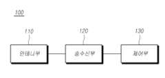
FIG. 3 is a block diagram of a vehicle radar device according to one embodiment of the present disclosure.
FIG. 4 is a drawing for explaining the structure of an antenna device equipped in a radar device according to one embodiment of the present disclosure.
FIGS. 5 to 7 are diagrams for explaining reception of a reflected signal using a second transmitting antenna in a long-distance detection mode according to one embodiment of the present disclosure.
FIG. 8 is a diagram for explaining the production of a reflected signal by a virtual receiving antenna in a long-distance sensing mode according to one embodiment of the present disclosure.
FIG. 9 is a drawing for explaining a structure in which some of the first transmitting antennas are vertically spaced according to one embodiment of the present disclosure.
FIG. 10 is a diagram for explaining providing information on an object detected by a vehicle radar device according to one embodiment of the present disclosure to a driver assistance system.
FIG. 11 is a flowchart of a method for controlling a vehicle radar device according to one embodiment of the present disclosure.
이하, 본 개시의 일부 실시예들을 예시적인 도면을 통해 상세하게 설명한다. 각 도면의 구성요소들에 참조부호를 부가함에 있어서, 동일한 구성요소들에 대해서는 비록 다른 도면상에 표시되더라도 가능한 한 동일한 부호를 가질 수 있다. 또한, 본 개시를 설명함에 있어, 관련된 공지 구성 또는 기능에 대한 구체적인 설명이 본 개시의 요지를 흐릴 수 있다고 판단되는 경우에는 그 상세한 설명은 생략할 수 있다.Hereinafter, some embodiments of the present disclosure will be described in detail with reference to exemplary drawings. When adding reference numerals to components in each drawing, the same components may have the same numerals as much as possible even if they are shown in different drawings. In addition, when describing the present disclosure, if it is determined that a specific description of a related known configuration or function may obscure the gist of the present disclosure, the detailed description may be omitted.
또한, 본 개시의 구성 요소를 설명하는 데 있어서, 제 1, 제 2, A, B, (a), (b) 등의 용어를 사용할 수 있다. 이러한 용어는 그 구성 요소를 다른 구성 요소와 구별하기 위한 것일 뿐, 그 용어에 의해 해당 구성 요소의 본질이나 차례 또는 순서 등이 한정되지 않는다. 어떤 구성 요소가 다른 구성요소에 "연결", "결합" 또는 "접속"된다고 기재된 경우, 그 구성 요소는 그 다른 구성요소에 직접적으로 연결되거나 또는 접속될 수 있지만, 각 구성 요소 사이에 또 다른 구성 요소가 "연결", "결합" 또는 "접속"될 수도 있다고 이해되어야 할 것이다.Also, in describing components of the present disclosure, terms such as first, second, A, B, (a), (b), etc. may be used. These terms are only intended to distinguish the components from other components, and the nature, order, or sequence of the components are not limited by the terms. When it is described that a component is "connected," "coupled," or "connected" to another component, it should be understood that the component may be directly connected or connected to the other component, but another component may also be "connected," "coupled," or "connected" between each component.
다른 정의가 없다면, 본 개시에서 사용되는 모든 용어(기술 및 과학적 용어를 포함)는 본 개시의 실시예들이 속하는 기술분야에서 통상의 지식을 가진 자에게 공통적으로 이해될 수 있는 의미로 사용될 수 있을 것이다. 또 일반적으로 사용되는 사전에 정의되어 있는 용어들은 명백하게 특별히 정의되어 있지 않는 한 이상적으로 또는 과도하게 해석되지 않는다. 그리고 후술되는 용어들은 본 개시의 실시예들에서의 기능을 고려하여 정의된 용어들로서 이는 사용자, 운용자의 의도 또는 관례 등에 따라 달라질 수 있다. 그러므로 그 정의는 본 개시 전반에 걸친 내용을 토대로 내려져야 할 것이다.Unless otherwise defined, all terms (including technical and scientific terms) used in this disclosure may be used with a meaning that can be commonly understood by a person of ordinary skill in the art to which the embodiments of the present disclosure belong. In addition, terms defined in commonly used dictionaries shall not be ideally or excessively interpreted unless explicitly specifically defined. In addition, the terms described below are terms defined in consideration of their functions in the embodiments of the present disclosure, and this may vary depending on the intention or custom of the user or operator. Therefore, the definitions should be made based on the contents throughout the present disclosure.
본 개시에서, "제1 방향"은 지면에 대하여 수직인 방향을 의미하고, "제2 방향"은 제1 방향에 수직인 지면에 대하여 수평인 방향을 의미한다. 또한, "원거리 감지모드"는 차량으로부터 중장거리에 위치한 객체를 감지하기 위한 레이더 장치의 감지모드를 의미한다. 또한, "근거리 감지모드"는 차량으로부터 근거리에 위치한 객체를 감지하기 위한 레이더 장치의 감지모드를 의미한다. 또한, "채널"은 하나의 급전 라인(feeding line)으로 전력이 공급되는 어레이 안테나들을 의미한다. 또한, "객체에 대한 정보"는 레이더 장치의 감지영역 내에서 검출된 객체의 위치 정보 또는 속도 정보 등을 의미한다.In the present disclosure, the "first direction" means a direction perpendicular to the ground, and the "second direction" means a direction horizontal to the ground perpendicular to the first direction. In addition, the "long-distance detection mode" means a detection mode of the radar device for detecting an object located at a medium to long distance from a vehicle. In addition, the "short-distance detection mode" means a detection mode of the radar device for detecting an object located at a short distance from the vehicle. In addition, the "channel" means array antennas supplied with power by a single feeding line. In addition, the "information about the object" means location information or speed information, etc., of an object detected within a detection area of the radar device.
도 1은 본 개시와 관련된 차량에 구비된 레이더 장치의 탐지 영역을 나타낸 도면이다.Figure 1 is a drawing showing a detection area of a radar device equipped in a vehicle related to the present disclosure.
차량용 레이더 장치는 차량(10)의 전면부, 후면부, 또는 측면부 등 다양한 위치에 장착될 수 있으며, 도 1에서는 전면부에 장착되는 예가 도시되어 있다. 차량의 전방을 감지하는 레이더 장치는 원거리에 위치한 객체를 감지하기 위한 원거리 안테나와 근거리에 위치한 객체를 탐지하기 위한 근거리 안테나를 함께 포함한다. 근거리 송신 안테나는 근거리의 객체를 감지할 수 있도록 넓은 감지각도의 감지영역(20)을 갖도록 설정된다. 원거리 송신 안테나는 원거리에 있는 객체를 감지할 수 있도록 좁은 감지 각도의 감지영역(30)을 갖도록 설정된다.The vehicle radar device can be mounted in various locations, such as the front, rear, or side of the vehicle (10), and an example of mounting on the front is illustrated in FIG. 1. The radar device detecting the front of the vehicle includes a long-range antenna for detecting a long-range object and a short-range antenna for detecting a short-range object. The short-range transmitting antenna is set to have a detection area (20) with a wide detection angle so that it can detect a short-range object. The long-range transmitting antenna is set to have a detection area (30) with a narrow detection angle so that it can detect a long-range object.
차량(10)은 원거리 감지를 위한 안테나를 이용하여 원거리 감지영역(30)에 있는 객체를 탐지하고, 근거리 감지를 위한 안테나를 이용하여 근거리 감지영역(20)에 있는 객체를 탐지할 수 있다. 이러한 두 가지 감지 영역은 차량(10)으로부터 원거리에 있는 객체와 근거리에 있는 객체를 탐지해야 하는 상황이 모두 요구되기 때문에 필요하다. 예를 들어, 전방에 있는 차량을 추월하기 위해 좁고 긴 탐지 범위를 가지는 원거리 안테나가 필요하고, 보행자 또는 근접 상태에 있는 다른 차량과의 충돌을 방지하기 위해서는 넓고 짧은 탐지 범위를 가지는 근거리 안테나가 필요하게 된다.The vehicle (10) can detect an object in a long-distance detection area (30) using an antenna for long-distance detection, and can detect an object in a short-distance detection area (20) using an antenna for short-distance detection. These two detection areas are necessary because both a situation requiring detection of objects at a long distance from the vehicle (10) and objects at a short distance are required. For example, a long-distance antenna with a narrow and long detection range is required to overtake a vehicle ahead, and a short-distance antenna with a wide and short detection range is required to prevent a collision with a pedestrian or another vehicle in close proximity.
도 2는 본 개시와 관련된 원거리 및 근거리 감지를 위한 차량용 레이더 장치를 나타낸 도면이다.FIG. 2 is a drawing showing a vehicle radar device for long-distance and short-distance detection related to the present disclosure.
도 2를 참조하면, 원거리 안테나와 근거리 안테나를 포함하는 레이더 장치의 일 예가 도시되어 있다. 레이더 장치의 안테나부(40)는 원거리 안테나와 근거리 안테나를 포함한다. 원거리 안테나는 원거리 송신신호를 출력하는 원거리 송신 안테나(Tx0)와, 원거리 송신신호가 반사된 반사신호를 수신하기 위한 원거리 수신 안테나(Rx1, Rx2, Rx3)를 포함한다. 근거리 안테나는 근거리 송신신호를 출력하는 근거리 송신 안테나(Tx1)와 근거리 송신신호가 반사된 반사신호를 수신하기 위한 근거리 수신 안테나(Rx0)를 포함한다.Referring to FIG. 2, an example of a radar device including a long-range antenna and a short-range antenna is illustrated. The antenna unit (40) of the radar device includes a long-range antenna and a short-range antenna. The long-range antenna includes a long-range transmitting antenna (Tx0) that outputs a long-range transmission signal, and a long-range receiving antenna (Rx1, Rx2, Rx3) for receiving a reflected signal that is a reflection of the long-range transmission signal. The short-range antenna includes a short-range transmitting antenna (Tx1) that outputs a short-range transmission signal, and a short-range receiving antenna (Rx0) for receiving a reflected signal that is a reflection of the short-range transmission signal.
근거리 수신 안테나(Rx0) 및 원거리 수신 안테나(Rx1, Rx2, Rx3)는 공용화될 수 있다. 이 경우, 네 개의 수신 안테나 모두는 원거리 감지 시에는 원거리 송신신호가 반사된 반사신호를 수신하고, 근거리 감지 시에는 근거리 송신신호가 반사된 반사신호를 수신할 수 있다.The near-field receiving antenna (Rx0) and the far-field receiving antennas (Rx1, Rx2, Rx3) can be shared. In this case, all four receiving antennas can receive a reflected signal of a far-field transmission signal when far-field detection is performed, and a reflected signal of a near-field transmission signal when near-field detection is performed.
이 때, 원거리 송신 안테나와 원거리 수신 안테나, 근거리 송신 안테나와 근거리 수신 안테나는 각각 최소한 한 개 이상의 패치 안테나로 구성되는데, 수직 방향에 대한 안테나 신호의 방향성을 적절히 억제하기 위하여 두 개 이상의 패치 안테나를 지면에 대하여 수직 방향인 제1 방향으로 연결한 것을 어레이 안테나(Array Antenna)라고 한다. 도 2에는 각 어레이 안테나가 열 개의 패치 안테나로 이루어진 것으로 도시되었으나, 이는 일 예로서 이에 한정되는 것은 아니다. 각 어레이 안테나에 포함된 패치 안테나의 개수, 크기 및 형상 등은 필요에 따라 다르게 구현될 수 있다.At this time, the long-distance transmitting antenna and the long-distance receiving antenna, the short-distance transmitting antenna and the short-distance receiving antenna are each composed of at least one patch antenna, and an array antenna is formed by connecting two or more patch antennas in a first direction that is vertical to the ground in order to appropriately suppress the directionality of antenna signals in the vertical direction. In Fig. 2, each array antenna is illustrated as being composed of ten patch antennas, but this is only an example and is not limited thereto. The number, size, and shape of the patch antennas included in each array antenna may be implemented differently as needed.
레이더 장치는 원거리 송신 안테나와 근거리 송신 안테나를 통하여 송신신호를 송신하고, 원거리 수신 안테나 및 근거리 수신 안테나로부터 수신신호를 수신하는 송수신부(50)를 포함한다. 송수신부(50)는 감지모드에 따라 송신 안테나 및 수신 안테나를 선택하기 위한 스위칭 장치를 포함할 수 있다.The radar device includes a transceiver (50) that transmits a transmission signal through a long-distance transmission antenna and a short-distance transmission antenna, and receives a reception signal from a long-distance receiving antenna and a short-distance receiving antenna. The transceiver (50) may include a switching device for selecting a transmission antenna and a reception antenna according to a detection mode.
제어부(60)는 수신 안테나를 통하여 수신된 반사신호를 처리하여 감지영역 내의 객체에 대한 정보를 획득할 수 있다. 예를 들어, 제어부(60)는 수신 안테나를 통해 수신된 반사신호와 송신 안테나를 통해 송신된 송신신호에 대한 상관분석을 통해 대상 객체에 대한 신호를 검출할 수 있다.The control unit (60) can obtain information about an object within a detection area by processing a reflected signal received through a receiving antenna. For example, the control unit (60) can detect a signal for a target object through correlation analysis of a reflected signal received through a receiving antenna and a transmitted signal transmitted through a transmitting antenna.
한편, 수평 방향에 대한 안테나 신호의 방향성을 적절히 억제하기 위하여 2개 이상의 어레이 안테나가 동일한 간격으로 지면과 수평으로 배치될 수 있다. 이 때 하나의 급전 라인(feeding line)으로 전력이 공급되는 어레이 안테나들을 동일한 하나의 채널에 연결된 것으로 본다. 예를 들어, 도 2를 참조하면, 네 개의 어레이 안테나들이 한 개의 채널로 원거리 송신 안테나(Tx0)를 구성한다. 또한, 두 개의 어레이 안테나들이 한 개의 채널로 근거리 송신 안테나(Tx1)를 구성한다. 또한, 두 개의 어레이 안테나들이 한 개의 채널로 근거리 수신 안테나(Rx0)를 구성한다. 또한, 여섯 개의 어레이 안테나들이 각각 두 개씩 세 개의 채널로 원거리 수신 안테나(Rx1, Rx2, Rx3)를 구성한다.Meanwhile, in order to appropriately suppress the directionality of antenna signals in the horizontal direction, two or more array antennas may be arranged horizontally with the ground at equal intervals. In this case, the array antennas supplied with power by one feeding line are considered to be connected to the same one channel. For example, referring to FIG. 2, four array antennas form a long-distance transmitting antenna (Tx0) with one channel. In addition, two array antennas form a short-distance transmitting antenna (Tx1) with one channel. In addition, two array antennas form a short-distance receiving antenna (Rx0) with one channel. In addition, six array antennas form three long-distance receiving antennas (Rx1, Rx2, Rx3) with two channels each.
수평 방향의 각도 분해능을 향상시키기 위해서는 전체 채널에 있어서 수신용 안테나의 왼쪽 끝과 오른쪽 끝이 멀게 배치될 필요가 있다. 이를 위해서는 수신용 안테나의 채널 개수를 늘리거나 어레이 안테나의 간격을 충분히 넓게 할 필요가 있지만, 어레이 안테나의 간격이 사용되는 파장의 절반(λ/2)보다 넓으면 안테나 신호의 방향성이 손상될 수 있으므로, 채널의 개수와 어레이 안테나의 개수, 어레이 안테나의 간격을 효율적으로 조정하는 것이 필요하게 된다.In order to improve the horizontal angular resolution, the left and right ends of the receiving antennas need to be placed far apart in the entire channel. To do this, it is necessary to increase the number of receiving antenna channels or to make the spacing between the array antennas sufficiently wide. However, if the spacing between the array antennas is wider than half the wavelength used (λ/2), the directionality of the antenna signal may be damaged, so it is necessary to efficiently adjust the number of channels, the number of array antennas, and the spacing between the array antennas.
이하에서는, 첨부되는 도면을 참조하여 본 개시의 실시예들에 따른 차량용 레이더 장치 및 그 제어 방법을 설명한다.Hereinafter, a vehicle radar device and a control method thereof according to embodiments of the present disclosure will be described with reference to the attached drawings.
도 3은 본 개시의 일 실시예에 따른 차량용 레이더 장치의 블록도이다. 도 4는 본 개시의 일 실시예에 따른 레이더 장치에 구비된 안테나 장치의 구조를 설명하기 위한 도면이다.FIG. 3 is a block diagram of a vehicle radar device according to one embodiment of the present disclosure. FIG. 4 is a drawing for explaining the structure of an antenna device provided in a radar device according to one embodiment of the present disclosure.
도 3을 참조하면, 본 개시에 따른 레이더 장치(100)는 제1 송신 안테나, 제2 송신 안테나 및 수신 안테나를 포함하는 안테나부(110), 감지모드에 따라 제1 송신 안테나 및 제2 송신 안테나 중 어느 하나를 통하여 송신신호를 송신하고, 수신 안테나를 통하여 객체에서 반사된 반사신호를 수신하는 송수신부(120) 및 수신 안테나를 통하여 수신된 반사신호를 처리하여 객체에 대한 정보를 획득하는 제어부를 포함할 수 있다. 이러한 레이더 장치를 레이더 센서라고도 한다.Referring to FIG. 3, a radar device (100) according to the present disclosure may include an antenna unit (110) including a first transmitting antenna, a second transmitting antenna, and a receiving antenna, a transceiver unit (120) that transmits a transmission signal through one of the first transmitting antenna and the second transmitting antenna according to a detection mode and receives a reflection signal reflected from an object through the receiving antenna, and a control unit that processes the reflection signal received through the receiving antenna to obtain information about the object. Such a radar device is also called a radar sensor.
안테나부(110)는, 적어도 하나의 제1 송신 안테나, 제1 송신 안테나와 지면에 수평인 방향으로 소정의 거리만큼 이격 배치되는 적어도 하나의 제2 송신 안테나 및 연속하여 소정의 거리만큼 이격 배치되는 적어도 하나의 수신 안테나를 포함할 수 있다.The antenna unit (110) may include at least one first transmitting antenna, at least one second transmitting antenna spaced apart from the first transmitting antenna in a direction horizontal to the ground by a predetermined distance, and at least one receiving antenna spaced apart continuously by a predetermined distance.
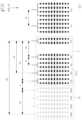
일 예로서, 도 4에 도시된 것과 같이, 제1 송신 안테나는 지면과 수직인 제1 방향으로 연장되는 어레이 안테나가 네 개씩 각각 하나의 채널로 연결된 두 개의 송신 안테나들(Tx0, Tx1)로 구성될 수 있다. 마찬가지로, 제2 송신 안테나는 두 개의 어레이 안테나들이 하나의 채널로 연결된 한 개의 송신 안테나(Tx2)로 구성될 수 있다. 수신 안테나는 여덟 개의 어레이 안테나들이 두 개씩 각각 하나의 채널로 연결된 네 개의 수신 안테나들(Rx0, Rx1, Rx2, Rx3)로 구성될 수 있다.As an example, as illustrated in FIG. 4, the first transmit antenna may be configured with two transmit antennas (Tx0, Tx1) each connected to a channel, with four array antennas extending in a first direction perpendicular to the ground. Similarly, the second transmit antenna may be configured with one transmit antenna (Tx2) each connected to a channel, with two array antennas. The receive antenna may be configured with four receive antennas (Rx0, Rx1, Rx2, Rx3) each connected to a channel, with eight array antennas.
즉, 일 예에 따른 레이더 장치는 세 개의 송신 채널(송신 안테나)과, 네 개의 수신 채널(수신 안테나)을 구비할 수 있다. 이하에서는 이러한 구조의 레이더 장치를 전제로 하여 설명하기로 한다. 다만, 이러한 레이더 장치의 구조는 일 예로서, 이에 한정되는 것은 아니다. 본 개시에 따른 레이더 장치는, L 개의 제1 송신 안테나, M 개의 제2 송신 안테나 및 N 개의 수신 안테나로 구성(L, M, N은 자연수)된 안테나부를 포함할 수 있으며, 각 안테나들은 적어도 하나의 어레이 안테나를 포함할 수 있다. 이러한 경우에도, 후술하는 내용은 실질적으로 동일하게 적용될 수 있다.That is, a radar device according to an example may have three transmission channels (transmission antennas) and four reception channels (reception antennas). The following description will be made on the premise of a radar device having such a structure. However, the structure of the radar device is merely an example and is not limited thereto. The radar device according to the present disclosure may include an antenna unit composed of L first transmission antennas, M second transmission antennas, and N reception antennas (L, M, N are natural numbers), and each of the antennas may include at least one array antenna. Even in this case, the contents described below may be substantially equally applied.
이러한 안테나부(110)의 구체적인 구성 및 동작에 대해서는 이하 관련 도면에서 더 상세하게 설명하기로 한다.The specific configuration and operation of this antenna unit (110) will be described in more detail in the related drawings below.
송수신부(120)는, 안테나부(110)에 포함된 제1 및 제2 송신 안테나 중 어느 하나로 스위칭(Switching)하여, 스위칭된 송신 안테나를 통해 송신신호를 송신하는 송신부와, 감지영역 내의 타겟인 객체에서 반사된 반사신호를 수신 안테나에서 수신하는 수신부를 포함할 수 있다.The transceiver (120) may include a transmitter that transmits a transmission signal through the switched transmission antenna by switching between the first and second transmission antennas included in the antenna unit (110), and a receiver that receives a reflected signal reflected from an object, which is a target within a detection area, through a receiving antenna.
일 예에 따라, 송수신부(120)에 포함된 송신부는, 스위칭된 송신 안테나에 할당된 한 개의 송신 채널 또는 복수 개의 송신 안테나에 할당된 멀티 송신채널에 대한 송신신호를 생성하는 발진부를 포함할 수 있다. 이러한 발진부는, 일 예로서, 전압 제어 발진기(VCO: Voltage-Controlled Oscillator) 및 오실레이터(Oscillator) 등을 포함할 수 있다.According to an example, the transmitter included in the transceiver (120) may include an oscillator that generates a transmission signal for one transmission channel assigned to a switched transmission antenna or for multiple transmission channels assigned to multiple transmission antennas. The oscillator may include, for example, a voltage-controlled oscillator (VCO) and an oscillator.
일 예에 따라, 송수신부(120)에 포함된 수신부는, 네 개의 수신 안테나(즉, 네 개의 수신 채널)를 통해 수신된 반사신호를 저잡음 증폭하는 저잡음 증폭부(LNA: Low Noise Amplifier)와, 저잡음 증폭된 수신신호를 믹싱하는 믹싱부(Mixer)와, 믹싱된 수신신호를 증폭하는 증폭부(Amplifier)와, 증폭된 수신신호를 디지털 변환하여 수신데이터를 생성하는 변환부(ADC: Analog Digital Converter) 등을 포함할 수 있다.For example, the receiving unit included in the transceiver (120) may include a low noise amplifier (LNA) that amplifies a reflected signal received through four receiving antennas (i.e., four receiving channels) with low noise, a mixing unit (Mixer) that mixes the low noise amplified receiving signal, an amplifier that amplifies the mixed receiving signal, and a conversion unit (ADC: Analog Digital Converter) that digitally converts the amplified receiving signal to generate receiving data.
더 구체적으로, 송수신부(120)는 근거리 감지를 위한 근거리 감지모드에서는 제2 송신 안테나(Tx2)를 통하여 송신신호를 송출하고, 모든 수신 안테나(Rx0, Rx1, Rx2, Rx3)에서 반사신호를 수신할 수 있다.More specifically, the transceiver (120) can transmit a transmission signal through the second transmission antenna (Tx2) in the short-range detection mode for short-range detection and receive reflected signals from all receiving antennas (Rx0, Rx1, Rx2, Rx3).
송수신부(120)는 중/장거리 감지를 위한 원거리 감지모드에서는 제1 송신 안테나(Tx0, Tx1)에서 코드 분할된 송신신호를 송출하고, 모든 수신 안테나(Rx0, Rx1, Rx2, Rx3)에서 반사신호를 수신할 수 있다. 이 경우, 일 실시예에 따라, 송수신부(120)는 원거리 감지모드에서 사용되지 않는 제2 송신 안테나(Tx2)를 수신 안테나로 이용하도록 스위칭할 수 있다. 즉, 원거리 감지모드에서 수신 안테나(Rx0, Rx1, Rx2, Rx3)와 함께 제2 송신 안테나(Tx2)를 통하여 반사신호를 수신할 수 있다. 이러한 송수신부(120)의 동작은 제어부(130)에 의해 제어될 수 있다.The transceiver (120) can transmit a code-divided transmission signal from the first transmission antenna (Tx0, Tx1) in the long-distance detection mode for medium/long-distance detection, and receive a reflected signal from all receiving antennas (Rx0, Rx1, Rx2, Rx3). In this case, according to one embodiment, the transceiver (120) can switch to use the second transmission antenna (Tx2) that is not used in the long-distance detection mode as a receiving antenna. That is, the reflected signal can be received through the second transmission antenna (Tx2) together with the receiving antennas (Rx0, Rx1, Rx2, Rx3) in the long-distance detection mode. Such operation of the transceiver (120) can be controlled by the control unit (130).
제어부(130)는 송신신호와 수신된 반사신호를 처리하여 객체에 대한 정보, 예를 들어, 위치정보를 산출할 수 있다. 더 구체적으로, 근거리 감지모드에서, 제어부(130)는 단일의 제2 송신 안테나(Tx2)를 통하여 송신된 송신신호와 수신 안테나(Rx0, Rx1, Rx2, Rx3)에서 수신된 수신신호를 이용하여 근거리에 있는 객체의 방위각과 같은 근거리 수평정보를 획득할 수 있다. 도 4를 참조하면, 수신 안테나들 사이의 간격이 A라 할 때, 근거리 감지모드에서의 수신 안테나의 개구는 3A가 될 수 있다.The control unit (130) can process the transmission signal and the received reflection signal to derive information about the object, for example, location information. More specifically, in the short-range detection mode, the control unit (130) can obtain short-range horizontal information, such as the azimuth of the object at a short range, by using the transmission signal transmitted through the single second transmission antenna (Tx2) and the reception signals received from the reception antennas (Rx0, Rx1, Rx2, Rx3). Referring to FIG. 4, when the spacing between the reception antennas is A, the aperture of the reception antenna in the short-range detection mode can be 3A.
또한, 원거리 감지모드에서, 제어부(130)는 제1 송신 안테나(Tx0, Tx1)에서 코드 분할되어 송신된 송신신호와 수신 안테나(Rx0, Rx1, Rx2, Rx3) 및 제2 송신 안테나(Tx2)에서 수신된 반사신호를 이용하여 중장거리에 있는 객체의 방위각(azimuth angle)과 같은 중장거리 수평정보를 획득할 수 있다. 제어부(130)는 제1 송신 안테나(Tx0, Tx1)를 통하여 송신신호를 송신하는 경우, 제2 송신 안테나(Tx2) 및 수신 안테나(Rx0, Rx1, Rx2, Rx3)를 통하여 반사신호를 수신하도록 상기 송수신부(120)를 제어할 수 있다.In addition, in the long-distance detection mode, the control unit (130) can obtain medium- to long-distance horizontal information, such as an azimuth angle, of an object at a medium- to long-distance by using a transmission signal transmitted by being code-divided from the first transmission antenna (Tx0, Tx1) and a reflection signal received from the receiving antennas (Rx0, Rx1, Rx2, Rx3) and the second transmission antenna (Tx2). When the control unit (130) transmits a transmission signal through the first transmission antenna (Tx0, Tx1), the control unit (130) can control the transceiver (120) to receive a reflection signal through the second transmission antenna (Tx2) and the receiving antennas (Rx0, Rx1, Rx2, Rx3).
일 예에 따라, 제1 송신안테나(Tx0, Tx1)가 서로 제1 방향으로 이격되어 배치되는 경우, 제어부(130)는 객체의 수직각도(elevation angle) 등과 같은 수직정보를 더 획득할 수 있다.For example, when the first transmission antennas (Tx0, Tx1) are arranged spaced apart from each other in the first direction, the control unit (130) can obtain additional vertical information, such as the elevation angle of the object.
일 예에 따라, 제어부(130)는, 많은 연산량을 필요로 하는 신호 처리를 제1 처리부와 제2 처리부에 효율적으로 분배함으로써, 비용을 줄이고, 동시에 하드웨어 사이즈를 축소하도록 구현될 수 있다.For example, the control unit (130) can be implemented to reduce costs and at the same time reduce hardware size by efficiently distributing signal processing requiring a large amount of computation to the first processing unit and the second processing unit.
제어부(130)에 포함된 제1 처리부는, 제2 처리부를 위한 전 처리부(Pre-Processor)로서, 송신 데이터 및 수신 데이터를 획득하여, 획득된 송신 데이터에 근거한 발진부에서의 송신신호의 생성을 제어하고, 송신 데이터 및 수신 데이터를 동기화하며, 송신 데이터 및 수신 데이터를 주파수 변환할 수 있다.The first processing unit included in the control unit (130) is a preprocessor for the second processing unit, and can acquire transmission data and reception data, control the generation of a transmission signal in the oscillator based on the acquired transmission data, synchronize the transmission data and reception data, and frequency convert the transmission data and reception data.
제1 처리부는, 획득된 송신 데이터 및 획득된 수신 데이터를 한 주기당 처리 가능한 단위 샘플 사이즈로 데이터 버퍼링 한 이후, 주파수 변환을 수행할 수 있다. 제1 처리부에서 수행하는 주파수 변환에는, 고속 푸리에 변환(FFT: Fast Fourier Transform) 등과 같은 푸리에 변환이 이용될 수 있다.The first processing unit can perform frequency conversion after data buffering the acquired transmission data and acquired reception data into a unit sample size that can be processed per cycle. The frequency conversion performed in the first processing unit can utilize a Fourier transform such as a fast Fourier transform (FFT).
제2 처리부는, 제1 처리부의 처리 결과를 이용하여 실질적 처리를 수행하는 후 처리부(Post-Processor)로서, 제1 처리부에서 주파수 변환된 수신 데이터를 토대로 CFAR(Constant False Alarm Rate) 연산, 트래킹(Tracking) 연산 및 객체에 대한 타겟 선택(Target Selection) 연산 등을 수행하고, 객체에 대한 각도정보, 속도정보 및 거리정보 등을 추출할 수 있다.The second processing unit is a post-processor that performs actual processing using the processing results of the first processing unit. Based on the received data that has been frequency converted by the first processing unit, the second processing unit performs CFAR (Constant False Alarm Rate) operations, tracking operations, and target selection operations for objects, and can extract angle information, speed information, and distance information for objects.
제2 처리부는, 제1 처리부에서 이루어진 제1 푸리에 변환(FFT)된 신호에 대하여 제2 푸리에 변환을 할 수 있으며, 제2 푸리에 변환은, 일 예로서, 이산 푸리에 변환(DFT: Discrete Fourier Transform, 이하 "DFT"라 칭함)일 수 있다. 또한, DFT 중에서도, 첩-이산 푸리에 변환(Chirp-DFT)일 수 있다.The second processing unit can perform a second Fourier transform on the first Fourier transformed (FFT) signal produced by the first processing unit, and the second Fourier transform can be, for example, a discrete Fourier transform (DFT, hereinafter referred to as “DFT”). Additionally, among the DFTs, it can be a chirp-discrete Fourier transform (Chirp-DFT).
제2 처리부는 Chirp-DFT 등의 제2 푸리에 변환을 통해, 제2 푸리에 변환 길이에 해당하는 개수만큼의 주파수 값을 획득하고, 획득된 주파수 값을 토대로 각 첩(Chirp) 주기 동안 가장 큰 파워를 갖는 비트 주파수를 계산하고, 계산된 비트 주파수에 근거하여 객체의 속도 정보 및 거리 정보를 획득함으로써 객체를 탐지할 수 있다.The second processing unit obtains a number of frequency values corresponding to the length of the second Fourier transform through a second Fourier transform such as Chirp-DFT, calculates a beat frequency with the greatest power during each chirp period based on the obtained frequency values, and obtains velocity information and distance information of the object based on the calculated beat frequency, thereby detecting the object.
이에 따르면, 레이더 장치가 원거리 감지모드로 동작 중에는 이용되지 않는 제2 송신 안테나를 수신 안테나로 활용하여 수신 안테나의 개구를 확장함으로써, 추가적인 구성 없이, 각도 분해능이 향상된 레이더 장치를 제공할 수 있다.Accordingly, by utilizing a second transmitting antenna, which is not used while the radar device is operating in a long-distance detection mode, as a receiving antenna and expanding the aperture of the receiving antenna, a radar device with improved angular resolution can be provided without additional configuration.
이하에서는, 원거리 감지모드에서 레이더 장치(100) 수신 안테나의 개구의 확장을 통한 각도 분해능의 향상에 대하여 구체적으로 설명하기로 한다.Below, the improvement of angular resolution through expansion of the aperture of the receiving antenna of the radar device (100) in the long-distance detection mode will be specifically described.
도 5 내지 도 7은 본 개시의 일 실시예에 따른 원거리 감지모드에서의 제2 송신 안테나를 이용한 반사신호의 수신을 설명하기 위한 도면이다.FIGS. 5 to 7 are diagrams for explaining reception of a reflected signal using a second transmitting antenna in a long-distance detection mode according to one embodiment of the present disclosure.
도 5를 참조하면, 1 송신 안테나(Tx0, Tx1), 제2 송신 안테나(Tx2) 및 수신 안테나(Rx0, Rx1, Rx2, Rx3)는 지면과 수평인 제2 방향을 따라 순차적으로 이격되어 배치될 수 있다. 즉, 안테나부(110)에서, 제1 송신 안테나(Tx0, Tx1) 및 수신 안테나(Rx0, Rx1, Rx2, Rx3)는 제2 송신 안테나(Tx2)의 양측에 각각 배치될 수 있다.Referring to FIG. 5, the first transmitting antenna (Tx0, Tx1), the second transmitting antenna (Tx2), and the receiving antennas (Rx0, Rx1, Rx2, Rx3) may be sequentially spaced apart and arranged along a second direction that is horizontal to the ground. That is, in the antenna unit (110), the first transmitting antenna (Tx0, Tx1) and the receiving antennas (Rx0, Rx1, Rx2, Rx3) may be arranged on both sides of the second transmitting antenna (Tx2), respectively.
도 5에는 제1 송신 안테나(Tx0, Tx1)가 제2 송신 안테나(Tx2)의 좌측에 배치된 것으로 도시되어 있으나, 이는 일 예로서, 이에 한정되는 것은 아니다. 제1 송신 안테나(Tx0, Tx1)가 제2 송신 안테나(Tx2)의 우측에, 수신 안테나(Rx0, Rx1, Rx2, Rx3)가 제2 송신 안테나(Tx2)의 좌측에 배치될 수도 있다.Although FIG. 5 illustrates that the first transmitting antenna (Tx0, Tx1) is arranged to the left of the second transmitting antenna (Tx2), this is only an example and is not limited thereto. The first transmitting antenna (Tx0, Tx1) may be arranged to the right of the second transmitting antenna (Tx2), and the receiving antennas (Rx0, Rx1, Rx2, Rx3) may be arranged to the left of the second transmitting antenna (Tx2).
레이더 장치(100)의 원거리 감지모드에서는, 복수의 송신 안테나와 복수의 수신 안테나를 이용하며, 따라서, 다중입력 다중출력(Multi-Input Multi-Output; MIMO) 방식의 안테나 장치로 동작할 수 있다. 우선적으로, 도 5에서는 수신 안테나(Rx0, Rx1, Rx2, Rx3)에 관하여 설명하기로 한다.In the long-distance detection mode of the radar device (100), multiple transmitting antennas and multiple receiving antennas are used, and therefore, it can operate as an antenna device of the multi-input multi-output (MIMO) method. First, the receiving antennas (Rx0, Rx1, Rx2, Rx3) will be described in FIG. 5.
일 예에 따라, 코드분할된 송신신호가 송신되는 제1 송신 안테나(Tx0, Tx1) 각각은 지면과 수평인 제2 방향으로 4A만큼 이격되어 배치된 경우로 가정한다. 다만, 이는 일 예로서, 이에 한정되는 것은 아니며, 제1 송신 안테나(Tx0, Tx1) 사이의 거리는, 필요에 따라 다르게 설정될 수 있다.For example, it is assumed that each of the first transmission antennas (Tx0, Tx1) through which the code-divided transmission signal is transmitted is arranged to be spaced apart by 4A in a second direction that is horizontal to the ground. However, this is only an example and is not limited thereto, and the distance between the first transmission antennas (Tx0, Tx1) may be set differently as needed.
이 경우, 객체에서 반사된 반사신호를 수신하는 수신 안테나 입장에서는 동일한 형태의 신호이되 제1 코드 및 제2 코드로 분할된 반사신호가 공간적으로 제2 방향으로 4A만큼 시프트되어 수신되는 것과 동일한 효과를 가진다. 이 때, 실제 존재하는 수신 안테나와 구별되는 개념으로, 동시에 신호를 송신하는 송신 안테나의 수평 이격에 의하여 가상적으로 존재하게 되는 수신 안테나를 가상 수신 안테나로 표현할 수 있다.In this case, from the perspective of the receiving antenna that receives the reflected signal reflected from the object, it has the same effect as receiving the reflected signal that is the same type of signal but divided into the first code and the second code and spatially shifted by 4A in the second direction. At this time, as a concept that is distinguished from the actually existing receiving antenna, the receiving antenna that exists virtually due to the horizontal separation of the transmitting antenna that transmits the signal at the same time can be expressed as a virtual receiving antenna.
도 5에서 제1 송신 안테나(Tx0)를 기준으로 볼 때, 수신 안테나(Rx0, Rx1, Rx2, Rx3)는 실제로 존재하는 수신 안테나인 진성 수신 안테나(real Rx antenna)가 된다. 제1 송신 안테나(Tx0)를 기준으로 볼 때, 제2 코드의 송신신호를 동시에 전송하는 제1 송신 안테나(Tx1)가 수평 방향으로 4A만큼 이격되어 있기 때문에, 제1 송신 안테나(Tx1)에서 송신되는 신호를 수신하는 수신 안테나는 실제 위치보다 수평방향으로 4A만큼 시프트된 위치에 있는 것과 동일한 효과를 가지게 된다. 이렇게 시프트된 위치에 생성되는 수신 안테나를 가상 수신 안테나(virtual Rx Antenna)로 표현할 수 있다.In Fig. 5, with respect to the first transmitting antenna (Tx0), the receiving antennas (Rx0, Rx1, Rx2, Rx3) become real Rx antennas that actually exist. With respect to the first transmitting antenna (Tx0), since the first transmitting antenna (Tx1) that simultaneously transmits the transmission signal of the second code is horizontally spaced apart by 4A, the receiving antenna that receives the signal transmitted from the first transmitting antenna (Tx1) has the same effect as being at a position horizontally shifted by 4A from the actual position. The receiving antenna created at this shifted position can be expressed as a virtual Rx antenna.
실제 수신 안테나와 구분하기 위하여, 제1 송신 안테나(Tx1)의 송신신호를 수신하는 가상 수신 안테나를 VRx0, VRx1, VRx2, VRx3로 표시하며, 실제 수신 안테나를 실선으로, 가상 수신 안테나를 점선으로 표시한다.To distinguish them from actual receiving antennas, virtual receiving antennas that receive the transmission signal of the first transmitting antenna (Tx1) are indicated as VRx0, VRx1, VRx2, and VRx3, and actual receiving antennas are indicated by solid lines and virtual receiving antennas are indicated by dotted lines.
따라서, 도 5를 참조하면, 진성 수신 안테나로부터 4A만큼 이격된 위치에 진성 수신 안테나와 동일한 배열 형태를 가지는 총 네 개의 가상 수신 안테나(VRx0, VRx1, VRx2, VRx3)가 생성된다. 즉, 원거리 감지모드에서, 네 개 채널의 진성 수신 안테나(Rx0, Rx1, Rx2, Rx3)가 배치된 영역(R)과 네 개 채널의 가상 수신 안테나(VRx0, VRx1, VRx2, VRx3)가 배치된 영역(V)이 수신 안테나로서 동작할 수 있다.Accordingly, referring to FIG. 5, a total of four virtual receiving antennas (VRx0, VRx1, VRx2, VRx3) having the same arrangement form as the genuine receiving antennas are generated at positions spaced 4A apart from the genuine receiving antennas. That is, in the long-distance sensing mode, an area (R) where the genuine receiving antennas (Rx0, Rx1, Rx2, Rx3) of four channels are arranged and an area (V) where the virtual receiving antennas (VRx0, VRx1, VRx2, VRx3) of four channels are arranged can operate as receiving antennas.
결과적으로, 원거리 감지모드에서, 수신 안테나의 전체 개구는, 진성 수신 안테나 중 가장 좌측의 수신 안테나(Rx0)와 가상 수신 안테나 중 가장 우측의 수신 안테나(VRx3) 사이의 수평 거리인 7A가 된다. 즉, MIMO 방식을 통하여, 수신단의 개구가 3A에서 7A로 확장될 수 있다.As a result, in the long-range sensing mode, the total aperture of the receiving antenna becomes 7A, which is the horizontal distance between the leftmost receiving antenna (Rx0) among the genuine receiving antennas and the rightmost receiving antenna (VRx3) among the virtual receiving antennas. In other words, through the MIMO method, the aperture of the receiving end can be expanded from 3A to 7A.
도 6을 참조하면, 원거리 감지모드에서, 제어부(130)는 근거리 감지모드에서 이용되는 제2 송신 안테나(Tx2)를 수신 안테나로 이용하도록 송수신부(120)를 제어할 수 있다. 이를 위하여, 제2 송신 안테나(Tx2)는 근거리 감지를 위한 송신신호의 송신 및 원거리 감지를 위한 송신신호가 반사된 반사신호의 수신 동작의 수행이 가능하도록 구현될 수 있다. 제2 송신 안테나(Tx2)는 제어부(130)의 제어에 따라 송신신호의 송신 및 반사신호의 수신 중 하나를 수행할 수 있다.Referring to FIG. 6, in the long-distance detection mode, the control unit (130) can control the transceiver (120) to use the second transmission antenna (Tx2) used in the short-distance detection mode as a receiving antenna. To this end, the second transmission antenna (Tx2) can be implemented to be capable of performing operations of transmitting a transmission signal for short-distance detection and receiving a reflected signal that is a reflection of the transmission signal for long-distance detection. The second transmission antenna (Tx2) can perform one of transmitting a transmission signal and receiving a reflected signal under the control of the control unit (130).
이 경우, 실제 수신 안테나가 배치된 영역은, 네 개 채널의 진성 수신 안테나(Rx0, Rx1, Rx2, Rx3)가 배치된 영역(R)에서 제2 송신 안테나(Tx2)를 포함하는 영역(E)로 확장될 수 있다. 일 예에 따라, 제2 송신 안테나(Tx2)와 수신 안테나(Rx0) 사이의 간격이 수평 거리 2A만큼 이격된 것으로 가정한다. 다만, 이는 일 예로서, 이에 한정되는 것은 아니다. 제2 송신 안테나(Tx2)와 수신 안테나(Rx0) 사이의 간격은, 필요에 따라 다르게 설정될 수 있다. 이 경우, 진성 수신 안테나가 배치된 영역(E)의 개구는 5A가 된다.In this case, the area where the actual receiving antennas are placed can be extended from the area (R) where the genuine receiving antennas (Rx0, Rx1, Rx2, Rx3) of four channels are placed to the area (E) including the second transmitting antenna (Tx2). As an example, it is assumed that the interval between the second transmitting antenna (Tx2) and the receiving antenna (Rx0) is spaced apart by a horizontal distance of 2A. However, this is only an example and is not limited thereto. The interval between the second transmitting antenna (Tx2) and the receiving antenna (Rx0) can be set differently as needed. In this case, the aperture of the area (E) where the genuine receiving antennas are placed becomes 5A.
도 5에서 전술한 것과 같이, 코드분할된 송신신호가 송신되는 제1 송신 안테나(Tx0, Tx1) 각각은 지면과 수평인 제2 방향으로 4A만큼 이격되어 배치된 경우를 가정한다. 이 경우, 객체에서 반사된 반사신호를 수신하는 수신 안테나 입장에서는 동일한 형태의 신호이되 제1 코드 및 제2 코드로 분할된 반사신호가 공간적으로 제2 방향으로 4A만큼 시프트되어 수신되는 것과 동일한 효과를 가진다.As described above in Fig. 5, it is assumed that each of the first transmission antennas (Tx0, Tx1) through which the code-divided transmission signal is transmitted is arranged to be spaced apart by 4A in the second direction that is horizontal to the ground. In this case, from the perspective of the receiving antenna that receives the reflected signal reflected from the object, it has the same effect as if the reflected signal, which is the same type of signal but divided into the first code and the second code, is spatially shifted by 4A in the second direction.
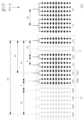
따라서, 도 7을 참조하면, 진성 수신 안테나(Tx2 및 Rx0, Rx1, Rx2, Rx3)로부터 4A만큼 이격된 위치에 진성 수신 안테나와 동일한 배열 형태를 가지는 총 다섯 개의 가상 수신 안테나(VTx2 및 VRx0, VRx1, VRx2, VRx3)가 생성된다. 이 경우, 진성 수신 안테나(Rx2)와 가상 수신 안테나(VTx2)의 위치는 중첩되게 된다.Therefore, referring to FIG. 7, a total of five virtual receive antennas (VTx2 and VRx0, VRx1, VRx2, VRx3) having the same arrangement form as the genuine receive antennas are created at positions spaced 4A apart from the genuine receive antennas (Tx2 and Rx0, Rx1, Rx2, Rx3). In this case, the positions of the genuine receive antenna (Rx2) and the virtual receive antenna (VTx2) overlap.
즉, 원거리 감지모드에서, 다섯 개 채널의 진성 수신 안테나(Tx2 및 Rx0, Rx1, Rx2, Rx3)가 배치된 영역(E)과 다섯 개 채널의 가상 수신 안테나(VTx2 및 VRx0, VRx1, VRx2, VRx3)가 배치된 영역(VE)이 수신 안테나로서 동작할 수 있다.That is, in the long-distance sensing mode, an area (E) where five channel genuine receiving antennas (Tx2 and Rx0, Rx1, Rx2, Rx3) are placed and an area (VE) where five channel virtual receiving antennas (VTx2 and VRx0, VRx1, VRx2, VRx3) are placed can operate as receiving antennas.
결과적으로, 원거리 감지모드에서, 수신 안테나의 전체 개구는, 진성 수신 안테나 중 가장 좌측의 제2 송신 안테나(Tx2)와 가상 수신 안테나 중 가장 우측의 수신 안테나(VRx3) 사이의 수평 거리인 9A가 된다. 즉, 제2 송신 안테나(Tx2)를 수신 안테나로 이용함으로써, 수신단의 개구가 9A로 확장될 수 있다.As a result, in the long-distance sensing mode, the total aperture of the receiving antenna becomes 9A, which is the horizontal distance between the second transmitting antenna (Tx2) on the leftmost side among the real receiving antennas and the receiving antenna (VRx3) on the rightmost side among the virtual receiving antennas. That is, by using the second transmitting antenna (Tx2) as a receiving antenna, the aperture of the receiving end can be expanded to 9A.
이에 따르면, 송신 안테나 중 감지모드에 따라 이용되지 않는 송신 안테나를 수신 안테나로 활용하여 수신 안테나의 개구를 확장함으로써, 추가적인 구성 없이 레이더 장치의 소형화와 함께 각도 분해능을 향상시킬 수 있다.Accordingly, by utilizing a transmitting antenna that is not used in the detection mode among the transmitting antennas as a receiving antenna and expanding the aperture of the receiving antenna, the angular resolution can be improved along with miniaturization of the radar device without additional configuration.
도 8은 본 개시의 일 실시예에 따른 원거리 감지모드에서의 가상 수신 안테나에 의한 반사신호의 산출을 설명하기 위한 도면이다.FIG. 8 is a diagram for explaining the production of a reflected signal by a virtual receiving antenna in a long-distance sensing mode according to one embodiment of the present disclosure.
도 7에서 전술한 것과 같이, 다섯 개 채널의 진성 수신 안테나(Tx2 및 Rx0, Rx1, Rx2, Rx3)가 배치된 영역(E)에서 제2 송신 안테나(Tx2)와 수신 안테나(Rx0) 사이가 2A 만큼 이격되어 있는 경우를 가정한다. 만약, 수신 안테나들 사이의 간격인 수평 거리 A가 송신신호의 반 파장으로 설정된 경우, 제2 송신 안테나(Tx2)와 수신 안테나(Rx0) 사이의 거리가 반 파장보다 길게 되어, 동일한 공분산 행렬(covariance matrix)을 생성하는 서로 다른 두 개의 각도 성분이 발생하게 된다. 이는 전파의 도달각도(direction-of-arrival) 추정을 모호하게 하는 공간적 모호성(spatial ambiguity)으로 표현되며, 최종적으로 그레이팅 로브(grating lobe)에 의한 고스트(ghost)를 발생시킬 수 있다.As described above in Fig. 7, it is assumed that in an area (E) where five channel genuine receiving antennas (Tx2 and Rx0, Rx1, Rx2, Rx3) are arranged, the second transmitting antenna (Tx2) and the receiving antenna (Rx0) are spaced apart by 2A. If the horizontal distance A between the receiving antennas is set to half a wavelength of a transmission signal, the distance between the second transmitting antenna (Tx2) and the receiving antenna (Rx0) becomes longer than the half wavelength, so that two different angular components that generate the same covariance matrix are generated. This is expressed as spatial ambiguity that obscures the estimation of the direction-of-arrival of the radio wave, and may ultimately cause a ghost due to a grating lobe.
이를 방지하기 위하여, 제어부(130)는, 도 8에 도시된 것과 같이, 제2 송신 안테나(Tx2) 및 수신 안테나(Rx0) 사이에 위치하는 가상 수신 안테나(VRx4)를 생성할 수 있다. 가상 수신 안테나(VRx4)는 제2 송신 안테나(Tx2) 및 수신 안테나(Rx0)와 각각 A만큼 이격되도록 배치될 수 있다.To prevent this, the control unit (130) may generate a virtual receiving antenna (VRx4) positioned between the second transmitting antenna (Tx2) and the receiving antenna (Rx0), as illustrated in FIG. 8. The virtual receiving antenna (VRx4) may be positioned to be spaced apart from the second transmitting antenna (Tx2) and the receiving antenna (Rx0) by A, respectively.
다만, 이는 제2 송신 안테나(Tx2) 및 수신 안테나(Rx0) 사이의 간격이 2A인 경우를 전제로 하는 것으로, 이에 한정되는 것은 아니다. 예를 들어, 제2 송신 안테나(Tx2) 및 수신 안테나(Rx0) 사이의 간격이 3A인 경우, 제2 송신 안테나(Tx2) 및 수신 안테나(Rx0) 사이에 A만큼 이격된 두 개의 가상 수신 안테나가 배치될 수 있다.However, this is based on the assumption that the spacing between the second transmitting antenna (Tx2) and the receiving antenna (Rx0) is 2A, and is not limited thereto. For example, if the spacing between the second transmitting antenna (Tx2) and the receiving antenna (Rx0) is 3A, two virtual receiving antennas spaced apart by A may be placed between the second transmitting antenna (Tx2) and the receiving antenna (Rx0).
즉, 원거리 감지모드에서, 다섯 개 채널의 진성 수신 안테나(Tx2 및 Rx0, Rx1, Rx2, Rx3) 및 한 개 채널의 가상 수신 안테나(VRx4)가 배치된 영역(S)과 다섯 개 채널의 가상 수신 안테나(VTx2 및 VRx0, VRx1, VRx2, VRx3)가 배치된 영역(VE)이 수신 안테나로서 동작할 수 있다. 또는, 상기 영역(S) 및 상기 영역(S)가 4A만큼 시프트된 영역(VS)이 수신 안테나로 동작할 수 있다. 이 경우, 영역(VS) 내의 가상 수신 안테나(VTx2) 및 생성된 가상 수신 안테나(VRx4)가 시프트된 가상 수신 안테나(VRx4')는 영역(S) 내의 진성 수신 안테나(Rx2, Rx3)와 중첩되게 된다. 따라서, 실질적인 수신단의 개구는 두 경우가 동일하게 된다.That is, in the long-distance sensing mode, a region (S) in which five channel genuine receiving antennas (Tx2 and Rx0, Rx1, Rx2, Rx3) and one channel virtual receiving antenna (VRx4) are arranged and a region (VE) in which five channel virtual receiving antennas (VTx2 and VRx0, VRx1, VRx2, VRx3) are arranged can operate as receiving antennas. Alternatively, the region (S) and a region (VS) in which the region (S) is shifted by 4A can operate as receiving antennas. In this case, the virtual receiving antenna (VTx2) in the region (VS) and the virtual receiving antenna (VRx4') in which the generated virtual receiving antenna (VRx4) is shifted overlap with the genuine receiving antennas (Rx2, Rx3) in the region (S). Therefore, the aperture of the actual receiving terminal becomes the same in both cases.
결과적으로, 원거리 감지모드에서, 수신 안테나의 전체 개구는, 진성 수신 안테나 중 가장 좌측의 제2 송신 안테나(Tx2)와 가상 수신 안테나 중 가장 우측의 수신 안테나(VRx3) 사이의 수평 거리인 9A가 된다. 또한, 수신단의 전체 개구 내의 열 개의 수신 안테나는 모두 동일한 간격인 수평 거리 A로 배치될 수 있다.As a result, in the long-range sensing mode, the overall aperture of the receiving antennas becomes 9A, which is the horizontal distance between the second transmitting antenna (Tx2) on the leftmost side among the real receiving antennas and the receiving antenna (VRx3) on the rightmost side among the virtual receiving antennas. In addition, all ten receiving antennas within the overall aperture of the receiving end can be arranged at the same horizontal distance A.
제어부(130)는 가상 수신 안테나(VRx4)에 의해 수신된 반사신호를 산출할 수 있다. 이 경우, 제어부(130)는 제1 송신 안테나를 통하여 송신된 송신신호 및 제2 송신 안테나 및 수신 안테나를 통하여 수신된 반사신호에 기초하여 가상 수신 안테나(VRx4)에 의한 반사신호를 산출할 수 있다.The control unit (130) can calculate a reflected signal received by the virtual receiving antenna (VRx4). In this case, the control unit (130) can calculate a reflected signal by the virtual receiving antenna (VRx4) based on a transmission signal transmitted through the first transmitting antenna and a reflected signal received through the second transmitting antenna and the receiving antenna.
제어부(130)는 수신된 반사신호 및 산출된 반사신호에 기초하여 송신신호와의 상관관계에 따라 객체에 대한 위치 정보 등을 획득할 수 있다.The control unit (130) can obtain location information about the object, etc. based on the received reflection signal and the generated reflection signal and the correlation with the transmission signal.
이에 따르면, 수신 안테나로 활용되는 송신 안테나와 수신 안테나 사이에 가상 안테나를 구현함으로써, 수신 안테나들 사이의 거리가 중심 주파수의 반 파장보다 멀어지는 경우에 발생할 수 있는 그레이팅 로브에 의한 고스트 타겟을 제거할 수 있다.Accordingly, by implementing a virtual antenna between a transmitting antenna and a receiving antenna used as a receiving antenna, it is possible to eliminate ghost targets caused by grating lobes that may occur when the distance between the receiving antennas becomes further than half a wavelength of the center frequency.
도 9는 본 개시의 일 실시예에 따른 제1 송신 안테나 중 일부가 수직으로 이격된 구조를 설명하기 위한 도면이다.FIG. 9 is a drawing for explaining a structure in which some of the first transmitting antennas are vertically spaced according to one embodiment of the present disclosure.
일 예에 따라, 제1 송신 안테나가 복수의 채널로 이루어진 경우, 복수의 채널 중 적어도 하나는 지면과 수직인 제1 방향을 따라 소정의 거리만큼 이격되어 배치될 수 있다. 도 9를 참조하면, 제1 송신 안테나(Tx0, Tx1)는 두 개의 채널로 구성되므로, 제1 송신 안테나(Tx1)는 제1 송신 안테나(Tx0)보다 수직 거리 B만큼 낮게 배치될 수 있다.For example, when the first transmitting antenna is composed of a plurality of channels, at least one of the plurality of channels may be arranged to be spaced apart from the ground by a predetermined distance along a first direction perpendicular to the ground. Referring to FIG. 9, since the first transmitting antenna (Tx0, Tx1) is composed of two channels, the first transmitting antenna (Tx1) may be arranged lower by a vertical distance B than the first transmitting antenna (Tx0).
이와 같이, 송신 안테나들의 수직 이격을 이용하여, 제어부(130)는 송신신호와 수신신호를 처리하여 객체의 위치 정보 중 객체의 수직 각도(elevation angle) 등과 같은 수직 정보를 더 획득할 수 있다.In this way, by utilizing the vertical separation of the transmitting antennas, the control unit (130) can process the transmitting signal and the receiving signal to obtain additional vertical information, such as the vertical angle of the object (elevation angle), among the object's position information.
다만, 이는 수직 방향의 정보를 획득하기 위한 것으로, 이와 수직인 수평 방향의 정보를 획득하기 위하여 도 3 내지 도 8에서 전술한 내용은, 도 9에 도시된 구조의 안테나부(110)에 대해서도 실질적으로 동일하게 적용될 수 있다. 따라서, 이에 대한 구체적인 설명은 중복 기재를 피하기 위해 생략하기로 한다.However, this is for obtaining vertical information, and the contents described above in FIGS. 3 to 8 for obtaining horizontal information perpendicular thereto can be substantially equally applied to the antenna unit (110) of the structure illustrated in FIG. 9. Therefore, a detailed description thereof will be omitted to avoid redundant description.
이에 따르면, 수직으로 이격된 송신 안테나들이 적용된 레이더 장치에 대해서도, 수직 정보의 획득과 함께, 레이더 장치의 소형화 및 각도 분해능의 향상을 도모할 수 있다.Accordingly, even for a radar device to which vertically spaced transmitting antennas are applied, it is possible to achieve miniaturization of the radar device and improvement of angular resolution along with acquisition of vertical information.
도 10은 본 개시의 일 실시예에 따른 차량용 레이더 장치에서 감지된 객체에 대한 정보를 운전자 보조 시스템에 제공하는 것을 설명하기 위한 도면이다.FIG. 10 is a diagram for explaining providing information on an object detected by a vehicle radar device according to one embodiment of the present disclosure to a driver assistance system.
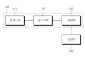
도 10을 참조하면, 레이더 장치(100)는 차량에 구비된 운전자 보조 시스템(ADAS)과 데이터를 송수신할 수 있다. 제어부(130)는 레이더 장치(100)가 설치된 차량에 포함된 운전자 보조 시스템(Advanced Driver Assistance Systems; ADAS, 200)에 객체에 대한 정보를 제공할 수 있다.Referring to FIG. 10, the radar device (100) can transmit and receive data with an Advanced Driver Assistance System (ADAS) equipped in a vehicle. The control unit (130) can provide information about an object to an Advanced Driver Assistance System (ADAS, 200) included in a vehicle in which the radar device (100) is installed.
여기서, 운전자 보조 시스템은 자율 주행 시스템(autonomous driving system), 반자율 주행 시스템(semi-autonomous driving system), 자동 주차 시스템(automated parking system), 블라인드 스팟 감지 시스템(blind spot detection system), 후측면 접근 차량 경고 시스템(cross traffic alert system), 차선 변경 및 병합 보조 시스템(lane change and merge aid system), 자동 긴급 제동 시스템(automatic emergency braking system), 보행자 감지 시스템(pedestrian detection system), 회전 보조(turn assist) 및 교차로 충돌 완화 시스템(intersection collision mitigation system)으로 구성된 그룹으로부터 선택된 적어도 하나의 시스템을 포함할 수 있다. 여기서 설명하는 운전자 보조 시스템의 용어 및 명칭은 예시적으로 개시한 것으로 이에 한정되지 않는다.Here, the driver assistance system may include at least one system selected from the group consisting of an autonomous driving system, a semi-autonomous driving system, an automated parking system, a blind spot detection system, a cross traffic alert system, a lane change and merge aid system, an automatic emergency braking system, a pedestrian detection system, a turn assist, and an intersection collision mitigation system. The terms and names of the driver assistance system described herein are provided by way of example and are not limited thereto.
제어부(130)는 레이더 장치(100)에 의한 센싱 데이터의 요청을 수신하면, 레이더 장치(100)를 구동하여, 송신신호를 송출하고, 객체에서 반사된 반사신호를 수신하도록 제어할 수 있다. 제어부(130)는 수신된 반사신호에 기초하여 객체에 대한 정보를 획득하고, 센싱 데이터를 요청한 운전자 보조 시스템으로 획득된 객체에 대한 정보를 송신할 수 있다.When the control unit (130) receives a request for sensing data from the radar device (100), it can control the radar device (100) to drive the radar device (100) to transmit a transmission signal and receive a reflected signal reflected from an object. The control unit (130) can obtain information about the object based on the received reflected signal and transmit the obtained information about the object to the driver assistance system that requested the sensing data.
일 예에 따라, 운전자 보조 시스템은 차량에 구비된 카메라에 의해 캡쳐된 이미지 데이터를 더 이용할 수 있다. 이 경우, 캡쳐된 이미지 데이터는 레이더 장치(100)에서 감지된 센싱 데이터와 퓨전되어 이용될 수 있다.As an example, the driver assistance system may further utilize image data captured by a camera equipped in the vehicle. In this case, the captured image data may be fused with sensing data detected by the radar device (100) and utilized.
일 예에 따라, 제어부(130)는 차량에 대한 전반적인 제어를 수행하는 도메인 컨트롤 유닛(Domain Control Unit; DCU)으로 통합될 수 있다. 이 경우, 제어부(130)는 레이더 장치에서 생략되거나, 도메인 컨트롤 유닛의 제어에 따라 동작할 수 있다. 도메인 컨트롤 유닛은 수신된 반사신호를 처리하여 객체에 대한 정보를 획득하고, 획득된 정보에 기초하여 운전자 보조 시스템 중 하나 이상을 제어하도록 동작할 수 있다.As an example, the control unit (130) may be integrated into a domain control unit (DCU) that performs overall control of the vehicle. In this case, the control unit (130) may be omitted from the radar device or may operate under the control of the domain control unit. The domain control unit may process the received reflected signal to obtain information about the object and operate to control one or more of the driver assistance systems based on the obtained information.
또한, 운전자 보조 시스템은 자율 주행을 위한 자율 주행 모듈을 포함할 수도 있다. 또는, 운전자 보조 시스템에 포함되는 개별 시스템 모듈들의 제어를 통해서 도메인 컨트롤 유닛이 차량이 자율 주행을 수행하도록 제어할 수도 있다.Additionally, the driver assistance system may include an autonomous driving module for autonomous driving. Alternatively, the domain control unit may control the vehicle to perform autonomous driving by controlling individual system modules included in the driver assistance system.
이에 따르면, 레이더 장치에서 검출된 객체에 대한 정보를 차량에 구비된 운전자 보조 시스템에 제공함으로써, 차량의 운전자에게 안정성 및 편의를 제공할 수 있다.Accordingly, by providing information on objects detected by a radar device to a driver assistance system equipped in a vehicle, safety and convenience can be provided to the driver of the vehicle.
본 개시의 일 실시예에 따른 안테나 장치는, 레이더 장치에 사용되는 안테나 장치로서, 원거리 감지모드에서 송신신호를 송신하는 제1 송신 안테나, 근거리 감지모드에서 송신신호를 송신하는 제2 송신 안테나 및 객체에서 반사된 반사신호를 수신하는 수신 안테나를 포함하되, 제2 송신 안테나는 원거리 감지모드에서 객체에서 반사된 반사신호를 수신할 수 있다. 제1 송신 안테나, 제2 송신 안테나 및 수신 안테나는 각각 적어도 하나의 채널로 이루어지고, 각 채널은 적어도 하나의 어레이 안테나를 포함할 수 있다.An antenna device according to one embodiment of the present disclosure is an antenna device used in a radar device, comprising: a first transmitting antenna for transmitting a transmission signal in a long-distance detection mode; a second transmitting antenna for transmitting a transmission signal in a short-distance detection mode; and a receiving antenna for receiving a reflection signal reflected from an object, wherein the second transmitting antenna can receive the reflection signal reflected from the object in the long-distance detection mode. The first transmitting antenna, the second transmitting antenna, and the receiving antenna each include at least one channel, and each channel can include at least one array antenna.
안테나 장치는 제1 송신 안테나, 제2 송신 안테나 및 수신 안테나가 지면과 수평인 제2 방향을 따라 순차적으로 이격되어 배치될 수 있다. 또한, 안테나 장치가 원거리 감지모드에서 동작하는 경우, 제2 송신 안테나 및 수신 안테나 사이에서 가상 수신 안테나가 형성될 수 있다. 제1 송신 안테나가 복수의 채널로 이루어진 경우, 복수의 채널 중 적어도 하나는 지면과 수직인 제1 방향을 따라 소정의 거리만큼 이격되어 배치될 수 있다.The antenna device may be arranged such that the first transmitting antenna, the second transmitting antenna, and the receiving antenna are sequentially spaced apart from each other along a second direction that is horizontal to the ground. In addition, when the antenna device operates in a long-distance detection mode, a virtual receiving antenna may be formed between the second transmitting antenna and the receiving antenna. When the first transmitting antenna is composed of a plurality of channels, at least one of the plurality of channels may be arranged so as to be spaced apart from each other by a predetermined distance along a first direction that is vertical to the ground.
본 개시에 따른 안테나 장치는 도 3 내지 도 9에서 전술한 레이더 장치에 포함된 안테나부와 명칭만 다를 뿐, 구조 및 동작은 실질적으로 동일하므로, 중복 기재를 피하기 위하여 더 이상의 구체적인 설명은 생략하기로 한다.The antenna device according to the present disclosure is substantially the same in structure and operation as the antenna part included in the radar device described above in FIGS. 3 to 9, except for the difference in name; therefore, further detailed description will be omitted to avoid redundant description.
이에 따르면, 송신 안테나 중 감지 모드에 따라 이용되지 않는 송신 안테나를 수신 안테나로 활용하여 수신 안테나의 개구를 확장함으로써, 레이더 장치를 소형화하고 각도 분해능을 향상시킬 수 있다. 또한, 수신 안테나로 활용되는 송신 안테나와 수신 안테나 사이에 가상 안테나를 구현함으로써, 그레이팅 로브에 의한 고스트 타겟을 제거할 수 있다.Accordingly, by utilizing a transmitting antenna that is not used according to the detection mode among the transmitting antennas as a receiving antenna and expanding the aperture of the receiving antenna, the radar device can be miniaturized and the angular resolution can be improved. In addition, by implementing a virtual antenna between the transmitting antenna and the receiving antenna that are utilized as receiving antennas, ghost targets caused by grating lobes can be eliminated.
본 개시에 따른 차량용 레이더 장치의 제어 방법은 전술한 차량용 레이더 장치(100)에서 구현될 수 있다. 이하 필요한 도면들을 참조하여, 본 개시에 따른 차량용 레이더 장치의 제어 방법과, 이를 구현하기 위한 차량용 레이더 장치(100)의 동작을 상세히 설명하기로 한다.The method for controlling a vehicle radar device according to the present disclosure can be implemented in the vehicle radar device (100) described above. With reference to the necessary drawings below, the method for controlling a vehicle radar device according to the present disclosure and the operation of the vehicle radar device (100) for implementing the same will be described in detail.
도 11은 본 개시의 일 실시예에 따른 차량용 레이더 장치의 제어 방법에 대한 흐름도이다. 제1 송신 안테나, 제2 송신 안테나 및 수신 안테나를 포함하는 안테나부가 구비된 레이더 장치Fig. 11 is a flow chart of a method for controlling a vehicle radar device according to one embodiment of the present disclosure. A radar device having an antenna section including a first transmitting antenna, a second transmitting antenna, and a receiving antenna.
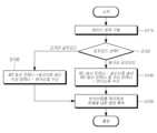
도 11을 참조하면, 차량의 주행 중 레이더 장치에 의한 센싱 데이터가 요청되는 경우, 레이더 장치가 구동될 수 있다[S110]. 다만, 이는 일 예로서, 이에 한정되는 것은 아니다. 레이더 장치는 차량의 시동 시부터 구동될 수 있다.Referring to Fig. 11, when sensing data by a radar device is requested while the vehicle is driving, the radar device may be driven [S110]. However, this is only an example and is not limited thereto. The radar device may be driven from the time the vehicle is started.
레이더 장치는 센싱 데이터가 요청된 상황에 따라, 원거리 감지모드 및 근거리 감지모드 중 어느 하나의 감지모드를 선택할 수 있다[S120]. 예를 들어, 전방에 있는 차량에 대한 추월 시도가 있는 경우, 원거리 감지모드가 선택될 수 있다. 또는, 차량이 주차 중인 경우, 차량 주변의 보행자 또는 객체와의 충돌을 방지하기 위해서 넓은 탐지 범위를 가지는 근거리 감지모드가 선택될 수 있다.The radar device can select either a long-distance detection mode or a short-distance detection mode depending on the situation in which sensing data is requested [S120]. For example, when there is an attempt to overtake a vehicle in front, the long-distance detection mode can be selected. Or, when the vehicle is parked, the short-distance detection mode with a wide detection range can be selected to prevent collision with pedestrians or objects around the vehicle.
다시, 도 11을 참조하면, 레이더 장치는 원거리 감지모드가 선택되면, 제1 송신 안테나를 통하여 송신신호를 송신하고, 제2 송신 안테나 및 수신 안테나를 통하여 객체에서 반사된 반사신호를 수신할 수 있다[S130].Again, referring to FIG. 11, when the long-distance detection mode is selected, the radar device can transmit a transmission signal through the first transmission antenna and receive a reflection signal reflected from an object through the second transmission antenna and the receiving antenna [S130].
레이더 장치는 적어도 하나의 제1 송신 안테나, 제1 송신 안테나와 지면에 수평인 방향으로 소정의 거리만큼 이격 배치되는 적어도 하나의 제2 송신 안테나 및 동일 방향으로 연속하여 소정의 거리만큼 이격 배치되는 적어도 하나의 수신 안테나를 포함할 수 있다. 일 예로서, 도 4에 도시된 것과 같이, 레이더 장치는 두 개의 송신 안테나들(Tx0, Tx1)로 구성된 제1 송신 안테나, 한 개의 송신 안테나(Tx2)로 구성된 제2 송신 안테나 및 네 개의 수신 안테나들(Rx0, Rx1, Rx2, Rx3)을 포함할 수 있다. 즉, 일 예에 따른 레이더 장치는 세 개의 송신 채널(송신 안테나)과, 네 개의 수신 채널(수신 안테나)을 구비할 수 있다. 이하에서는 이러한 구조의 레이더 장치를 전제로 하여 설명하기로 한다. 다만, 이러한 레이더 장치의 구조는 일 예로서, 이에 한정되는 것은 아니다.A radar device may include at least one first transmitting antenna, at least one second transmitting antenna spaced apart from the first transmitting antenna in a direction horizontal to the ground by a predetermined distance, and at least one receiving antenna spaced apart continuously in the same direction by a predetermined distance. As an example, as illustrated in FIG. 4, the radar device may include a first transmitting antenna composed of two transmitting antennas (Tx0, Tx1), a second transmitting antenna composed of one transmitting antenna (Tx2), and four receiving antennas (Rx0, Rx1, Rx2, Rx3). That is, a radar device according to an example may have three transmitting channels (transmitting antennas) and four receiving channels (receiving antennas). The following description will be made on the premise that a radar device having such a structure is used. However, the structure of the radar device is not limited thereto.
레이더 장치는 중/장거리 감지를 위한 원거리 감지모드가 선택되면, 제1 송신 안테나(Tx0, Tx1)에서 코드 분할된 송신신호를 송출하고, 모든 수신 안테나(Rx0, Rx1, Rx2, Rx3)에서 반사신호를 수신할 수 있다. 이 경우, 레이더 장치는 원거리 감지모드에서 사용되지 않는 제2 송신 안테나(Tx2)를 수신 안테나로 이용하도록 스위칭할 수 있다. 즉, 원거리 감지모드에서는 수신 안테나(Rx0, Rx1, Rx2, Rx3)와 함께 제2 송신 안테나(Tx2)를 통하여 반사신호가 수신될 수 있다.When the long-range detection mode for medium/long-range detection is selected, the radar device can transmit a code-divided transmission signal from the first transmission antenna (Tx0, Tx1) and receive a reflected signal from all receiving antennas (Rx0, Rx1, Rx2, Rx3). In this case, the radar device can switch to use the second transmission antenna (Tx2), which is not used in the long-range detection mode, as a receiving antenna. That is, in the long-range detection mode, the reflected signal can be received through the second transmission antenna (Tx2) together with the receiving antennas (Rx0, Rx1, Rx2, Rx3).
다시, 도 11을 참조하면, 레이더 장치는 근거리 감지모드가 선택되면, 제2 송신 안테나를 통하여 송신신호를 송신하고, 수신 안테나를 통하여 객체에서 반사된 반사신호를 수신할 수 있다[S140]. 레이더 장치는 근거리 감지를 위한 근거리 감지모드가 선택되면, 제2 송신 안테나(Tx2)를 통하여 송신신호를 송출하고, 모든 수신 안테나(Rx0, Rx1, Rx2, Rx3)에서 반사신호를 수신할 수 있다.Again, referring to FIG. 11, when the short-range detection mode is selected, the radar device can transmit a transmission signal through the second transmission antenna and receive a reflected signal reflected from an object through the receiving antenna [S140]. When the short-range detection mode for short-range detection is selected, the radar device can transmit a transmission signal through the second transmission antenna (Tx2) and receive reflected signals from all receiving antennas (Rx0, Rx1, Rx2, Rx3).
다시, 도 11을 참조하면, 레이더 장치는 원거리 감지모드에서 수신된 반사신호 또는 근거리 감지모드에서 수신된 반사신호를 처리하여 객체에 대한 정보를 획득할 수 있다[S150].Again, referring to FIG. 11, the radar device can obtain information about an object by processing a reflected signal received in a long-distance detection mode or a reflected signal received in a short-distance detection mode [S150].
레이더 장치는 송신신호와 수신된 반사신호를 처리하여 객체에 대한 정보, 예를 들어, 위치정보를 산출할 수 있다. 더 구체적으로, 근거리 감지모드에서, 레이더 장치는 단일의 제2 송신 안테나(Tx2)를 통하여 송신된 송신신호와 수신 안테나(Rx0, Rx1, Rx2, Rx3)에서 수신된 수신신호를 이용하여 근거리에 있는 객체의 방위각과 같은 근거리 수평정보를 획득할 수 있다.The radar device can process the transmitted signal and the received reflected signal to derive information about the object, for example, location information. More specifically, in the short-range detection mode, the radar device can obtain short-range horizontal information, such as the azimuth of the object at a short range, by using the transmitted signal transmitted through the single second transmitting antenna (Tx2) and the received signals received from the receiving antennas (Rx0, Rx1, Rx2, Rx3).
원거리 감지모드에서, 레이더 장치는 제1 송신 안테나(Tx0, Tx1)에서 코드 분할되어 송신된 송신신호와 수신 안테나(Rx0, Rx1, Rx2, Rx3) 및 제2 송신 안테나(Tx2)에서 수신된 반사신호를 이용하여 중장거리에 있는 객체의 방위각(azimuth angle)과 같은 중장거리 수평정보를 획득할 수 있다.In the long-range detection mode, the radar device can obtain mid- to long-range horizontal information, such as the azimuth angle of an object at a mid- to long-range, by using a transmission signal transmitted by being code-divided from a first transmission antenna (Tx0, Tx1) and a reflected signal received from the receiving antennas (Rx0, Rx1, Rx2, Rx3) and the second transmission antenna (Tx2).
또한, 제1 송신안테나(Tx0, Tx1) 각각이 서로 제1 방향으로 소정의 간격만큼 이격되어 배치되는 경우, 레이더 장치는 객체의 수직각도(elevation angle) 등과 같은 수직정보를 더 획득할 수 있다.In addition, when the first transmission antennas (Tx0, Tx1) are respectively arranged at a predetermined interval in the first direction, the radar device can obtain additional vertical information, such as the elevation angle of the object.
또한, 안테나 장치가 원거리 감지모드에서 동작하는 경우, 레이더 장치는 제2 송신 안테나(Tx2)와 수신 안테나(Rx0) 사이의 공간에 가상 수신 안테나를 생성할 수 있다. 제2 송신 안테나를 수신 안테나로 이용하여 수신단의 개구를 확장하는 경우, 제2 송신 안테나(Tx2)와 수신 안테나(Rx0) 사이의 거리가 송신신호의 반 파장보다 길다면, 그레이팅 로브(grating lobe)에 의한 고스트(ghost)가 발생될 수 있다. 이를 방지하기 위하여, 레이더 장치는 제2 송신 안테나(Tx2)와 수신 안테나(Rx0) 사이에 가상 수신 안테나를 형성하여, 수신 안테나들 사이의 간격을 반 파장 이하로 조정할 수 있다.In addition, when the antenna device operates in the long-distance detection mode, the radar device can create a virtual receiving antenna in the space between the second transmitting antenna (Tx2) and the receiving antenna (Rx0). When the second transmitting antenna is used as a receiving antenna to expand the aperture of the receiving end, if the distance between the second transmitting antenna (Tx2) and the receiving antenna (Rx0) is longer than half a wavelength of the transmission signal, a ghost due to a grating lobe may occur. To prevent this, the radar device can form a virtual receiving antenna between the second transmitting antenna (Tx2) and the receiving antenna (Rx0) and adjust the spacing between the receiving antennas to less than half a wavelength.
이에 따르면, 송신 안테나 중 감지 모드에 따라 이용되지 않는 송신 안테나를 수신 안테나로 활용하여 수신 안테나의 개구를 확장함으로써, 레이더 장치를 소형화하고 각도 분해능을 향상시킬 수 있다. 또한, 수신 안테나로 활용되는 송신 안테나와 수신 안테나 사이에 가상 안테나를 구현함으로써, 그레이팅 로브에 의한 고스트 타겟을 제거할 수 있다.Accordingly, by utilizing a transmitting antenna that is not used according to the detection mode among the transmitting antennas as a receiving antenna and expanding the aperture of the receiving antenna, the radar device can be miniaturized and the angular resolution can be improved. In addition, by implementing a virtual antenna between the transmitting antenna and the receiving antenna that are utilized as receiving antennas, ghost targets caused by grating lobes can be eliminated.
전술한 본 개시는, 프로그램이 기록된 매체에 컴퓨터가 읽을 수 있는 코드로서 구현하는 것이 가능하다. 컴퓨터가 읽을 수 있는 매체는, 컴퓨터 시스템에 의하여 읽혀질 수 있는 데이터가 저장되는 모든 종류의 기록장치를 포함한다. 컴퓨터가 읽을 수 있는 매체의 예로는, HDD(Hard Disk Drive), SSD(Solid State Disk), SDD(Silicon Disk Drive), ROM, RAM, CD-ROM, 자기 테이프, 플로피 디스크, 광 데이터 저장 장치 등이 있으며, 또한 캐리어 웨이브(예를 들어, 인터넷을 통한 전송)의 형태로 구현되는 것도 포함한다.The above-described present disclosure can be implemented as a computer-readable code on a medium having a program recorded thereon. The computer-readable medium includes all kinds of recording devices that store data that can be read by a computer system. Examples of the computer-readable medium include a hard disk drive (HDD), a solid state disk (SSD), a silicon disk drive (SDD), a ROM, a RAM, a CD-ROM, a magnetic tape, a floppy disk, an optical data storage device, and the like, and also includes those implemented in the form of a carrier wave (e.g., transmission via the Internet).
이상에서의 설명 및 첨부된 도면은 본 개시의 기술 사상을 예시적으로 나타낸 것에 불과한 것으로서, 본 개시가 속하는 기술 분야에서 통상의 지식을 가진 자라면 본 개시의 본질적인 특성에서 벗어나지 않는 범위에서 구성의 결합, 분리, 치환 및 변경 등의 다양한 수정 및 변형이 가능할 것이다. 따라서, 본 개시에 개시된 실시예들은 본 개시의 기술 사상을 한정하기 위한 것이 아니라 설명하기 위한 것이고, 이러한 실시예에 의하여 본 개시의 기술 사상의 범위가 한정되는 것은 아니다. 즉, 본 개시의 목적 범위 안에서라면, 그 모든 구성 요소들이 하나 이상으로 선택적으로 결합하여 동작할 수도 있다. 본 개시의 보호 범위는 아래의 청구범위에 의하여 해석되어야 하며, 그와 동등한 범위 내에 있는 모든 기술 사상은 본 개시의 권리범위에 포함되는 것으로 해석되어야 할 것이다.The above description and the attached drawings are merely illustrative of the technical idea of the present disclosure, and those skilled in the art to which the present disclosure pertains may make various modifications and variations, such as combination, separation, substitution, and change of the configuration, without departing from the essential characteristics of the present disclosure. Therefore, the embodiments disclosed in the present disclosure are not intended to limit the technical idea of the present disclosure but to explain it, and the scope of the technical idea of the present disclosure is not limited by these embodiments. That is, within the scope of the purpose of the present disclosure, all of the components may be selectively combined and operated one or more times. The protection scope of the present disclosure should be interpreted by the claims below, and all technical ideas within a scope equivalent thereto should be interpreted as being included in the scope of the rights of the present disclosure.
10: 차량20: 근거리 감지영역
20: 원거리 감지영역40: 안테나부
50: 송수신부60: 제어부
100: 레이더 장치110: 안테나부
120: 송수신부130: 제어부10: Vehicle 20: Close range detection area
20: Long distance detection area 40: Antenna section
50: Transmitter/Receiver 60: Control Unit
100: Radar device 110: Antenna section
120: Transmitter/Receiver 130: Control Unit
Claims (16)
Translated fromKorean감지모드에 따라 상기 제1 송신 안테나 및 상기 제2 송신 안테나 중 어느 하나를 통하여 송신신호를 송신하고, 상기 수신 안테나를 통하여 객체에서 반사된 반사신호를 수신하는 송수신부; 및
상기 수신 안테나를 통하여 수신된 반사신호를 처리하여 상기 객체에 대한 정보를 획득하는 제어부;를 포함하되,
상기 제어부는 상기 제1 송신 안테나를 통하여 송신신호를 송신하는 경우, 상기 제2 송신 안테나 및 상기 수신 안테나를 통하여 반사신호를 수신하도록 상기 송수신부를 제어하고,
상기 제1 송신 안테나, 상기 제2 송신 안테나 및 상기 수신 안테나는 지면과 수평인 제2 방향을 따라 순차적으로 이격되어 배치되고,
상기 제2 송신 안테나 및 상기 수신 안테나 사이에 위치하는 가상 수신 안테나에 의한 반사신호를 산출하고,
상기 제1 송신 안테나를 통하여 송신신호를 송신하는 경우, 상기 송신신호 및 상기 제2 송신 안테나 및 상기 수신 안테나를 통하여 수신된 반사신호에 기초하여 상기 가상 수신 안테나에 의한 반사신호를 산출하고,
상기 수신된 반사신호 및 상기 산출된 반사신호에 기초하여 상기 객체에 대한 정보를 획득하는 것을 특징으로 하는 레이더 장치.An antenna section including a first transmitting antenna, a second transmitting antenna, and a receiving antenna;
A transceiver unit that transmits a transmission signal through one of the first transmission antenna and the second transmission antenna according to the detection mode and receives a reflected signal reflected from an object through the receiving antenna; and
A control unit for obtaining information about the object by processing a reflected signal received through the receiving antenna; including:
The control unit controls the transceiver to receive a reflected signal through the second transmitting antenna and the receiving antenna when transmitting a transmission signal through the first transmitting antenna.
The first transmitting antenna, the second transmitting antenna, and the receiving antenna are sequentially spaced apart along a second direction that is horizontal to the ground,
Calculating a reflected signal by a virtual receiving antenna located between the second transmitting antenna and the receiving antenna,
When transmitting a transmission signal through the first transmission antenna, a reflection signal by the virtual receiving antenna is calculated based on the transmission signal and the reflection signal received through the second transmission antenna and the receiving antenna,
A radar device characterized by obtaining information about the object based on the received reflection signal and the calculated reflection signal.
상기 제1 송신 안테나, 상기 제2 송신 안테나 및 상기 수신 안테나는 각각 적어도 하나의 채널로 이루어지고, 각 채널은 적어도 하나의 어레이 안테나를 포함하는 레이더 장치.In paragraph 1,
A radar device wherein the first transmitting antenna, the second transmitting antenna, and the receiving antenna each comprise at least one channel, and each channel includes at least one array antenna.
상기 제1 송신 안테나가 복수의 채널로 이루어진 경우, 상기 복수의 채널 중 적어도 하나는 지면과 수직인 제1 방향을 따라 소정의 거리만큼 이격되어 배치되는 레이더 장치.In the second paragraph,
A radar device in which, when the first transmitting antenna is composed of a plurality of channels, at least one of the plurality of channels is arranged at a predetermined distance apart along a first direction perpendicular to the ground.
상기 제2 송신 안테나는 상기 제어부의 제어에 따라 송신신호의 송신 및 반사신호의 수신 중 하나를 수행하는 레이더 장치.In paragraph 1,
The second transmitting antenna is a radar device that performs one of transmitting a transmission signal and receiving a reflected signal under the control of the control unit.
상기 송수신부는 원거리 감지모드에서 상기 제1 송신 안테나를 통하여 송신신호를 송신하고, 근거리 감지모드에서 상기 제2 송신 안테나를 통하여 송신신호를 송신하는 레이더 장치.In paragraph 1,
The above-mentioned transceiver is a radar device that transmits a transmission signal through the first transmission antenna in a long-distance detection mode and transmits a transmission signal through the second transmission antenna in a short-distance detection mode.
상기 제어부는 상기 레이더 장치가 설치된 차량에 포함된 운전자 보조 시스템(Advanced Driver Assistance Systems, ADAS)에 상기 객체에 대한 정보를 제공하는 레이더 장치.In paragraph 1,
The above control unit is a radar device that provides information about the object to an Advanced Driver Assistance Systems (ADAS) included in a vehicle in which the radar device is installed.
상기 운전자 보조 시스템은 상기 차량에 구비된 카메라에 의해 캡쳐된 이미지 데이터를 더 이용하고,
상기 캡쳐된 이미지 데이터는 상기 레이더 장치에서 감지된 센싱 데이터와 퓨전되어 이용되는 레이더 장치.In Article 9,
The above driver assistance system further utilizes image data captured by a camera equipped in the vehicle,
A radar device in which the captured image data is fused with sensing data detected by the radar device and used.
원거리 감지모드에서 송신신호를 송신하는 제1 송신 안테나;
근거리 감지모드에서 송신신호를 송신하는 제2 송신 안테나; 및
객체에서 반사된 반사신호를 수신하는 수신 안테나;를 포함하되,
상기 제2 송신 안테나는 상기 원거리 감지모드에서 상기 객체에서 반사된 반사신호를 수신하고,
상기 제1 송신 안테나, 상기 제2 송신 안테나 및 상기 수신 안테나는 지면과 수평인 제2 방향을 따라 순차적으로 이격되어 배치되고,
상기 제2 송신 안테나 및 상기 수신 안테나 사이에서 가상 수신 안테나가 형성되고,
상기 제1 송신 안테나를 통하여 송신신호를 송신하는 경우, 상기 송신신호 및 상기 제2 송신 안테나 및 상기 수신 안테나를 통하여 수신된 반사신호에 기초하여 상기 가상 수신 안테나에 의한 반사신호를 산출하고,
상기 수신된 반사신호 및 상기 산출된 반사신호에 기초하여 상기 객체에 대한 정보를 획득하는 것을 특징으로 하는 안테나 장치.As an antenna device used in a radar device,
A first transmitting antenna for transmitting a transmission signal in a long-distance sensing mode;
a second transmitting antenna for transmitting a transmission signal in a near-field detection mode; and
A receiving antenna for receiving a reflected signal reflected from an object;
The second transmitting antenna receives a reflected signal reflected from the object in the long-distance detection mode,
The first transmitting antenna, the second transmitting antenna, and the receiving antenna are sequentially spaced apart along a second direction that is horizontal to the ground,
A virtual receiving antenna is formed between the second transmitting antenna and the receiving antenna,
When transmitting a transmission signal through the first transmission antenna, a reflection signal by the virtual receiving antenna is calculated based on the transmission signal and the reflection signal received through the second transmission antenna and the receiving antenna,
An antenna device characterized in that it obtains information about the object based on the received reflection signal and the calculated reflection signal.
상기 제1 송신 안테나, 상기 제2 송신 안테나 및 상기 수신 안테나는 각각 적어도 하나의 채널로 이루어지고, 각 채널은 적어도 하나의 어레이 안테나를 포함하는 안테나 장치.In Article 11,
An antenna device wherein the first transmitting antenna, the second transmitting antenna, and the receiving antenna each comprise at least one channel, and each channel includes at least one array antenna.
상기 제1 송신 안테나가 복수의 채널로 이루어진 경우, 상기 복수의 채널 중 적어도 하나는 지면과 수직인 제1 방향을 따라 소정의 거리만큼 이격되어 배치되는 안테나 장치.In Article 12,
An antenna device in which, when the first transmitting antenna is composed of a plurality of channels, at least one of the plurality of channels is arranged at a predetermined distance apart from the ground in a first direction perpendicular to the ground.
상기 제1 송신 안테나, 상기 제2 송신 안테나 및 상기 수신 안테나는 지면과 수평인 제2 방향을 따라 순차적으로 이격되어 배치되고,
상기 제2 송신 안테나 및 상기 수신 안테나 사이에 위치하는 가상 수신 안테나에 의한 반사신호를 산출하고,
상기 제1 송신 안테나를 통하여 송신신호를 송신하는 경우, 상기 송신신호 및 상기 제2 송신 안테나 및 상기 수신 안테나를 통하여 수신된 반사신호에 기초하여 상기 가상 수신 안테나에 의한 반사신호를 산출하고,
상기 수신된 반사신호 및 상기 산출된 반사신호에 기초하여 객체에 대한 정보를 획득하고,
원거리 감지모드 및 근거리 감지모드 중 어느 하나의 감지모드를 선택하는 단계;
상기 원거리 감지모드가 선택되면, 상기 제1 송신 안테나를 통하여 송신신호를 송신하고, 상기 제2 송신 안테나 및 상기 수신 안테나를 통하여 객체에서 반사된 반사신호를 수신하는 단계;
상기 근거리 감지모드가 선택되면, 상기 제2 송신 안테나를 통하여 송신신호를 송신하고, 상기 수신 안테나를 통하여 상기 객체에서 반사된 반사신호를 수신하는 단계; 및
상기 원거리 감지모드에서 수신된 반사신호 또는 상기 근거리 감지모드에서 수신된 반사신호를 처리하여 상기 객체에 대한 정보를 획득하는 단계;
를 포함하는 레이더 장치의 제어 방법.
A method for controlling a radar device having an antenna section including a first transmitting antenna, a second transmitting antenna, and a receiving antenna,
The first transmitting antenna, the second transmitting antenna, and the receiving antenna are sequentially spaced apart along a second direction that is horizontal to the ground,
Calculating a reflected signal by a virtual receiving antenna located between the second transmitting antenna and the receiving antenna,
When transmitting a transmission signal through the first transmission antenna, a reflection signal by the virtual receiving antenna is calculated based on the transmission signal and the reflection signal received through the second transmission antenna and the receiving antenna,
Obtain information about the object based on the received reflection signal and the generated reflection signal,
A step of selecting one of the detection modes among the long-distance detection mode and the short-distance detection mode;
When the above remote detection mode is selected, a step of transmitting a transmission signal through the first transmission antenna and receiving a reflection signal reflected from an object through the second transmission antenna and the receiving antenna;
When the above short-range detection mode is selected, a step of transmitting a transmission signal through the second transmission antenna and receiving a reflection signal reflected from the object through the receiving antenna; and
A step of obtaining information about the object by processing a reflection signal received in the long-distance detection mode or a reflection signal received in the short-distance detection mode;
A method for controlling a radar device including a .
Priority Applications (2)
| Application Number | Priority Date | Filing Date | Title |
|---|---|---|---|
| KR1020190027276AKR102814886B1 (en) | 2019-03-11 | 2019-03-11 | Radar apparatus, antenna apparatus for radar apparatus and control method of radar apparatus |
| US16/715,710US11579246B2 (en) | 2019-03-11 | 2019-12-16 | Radar apparatus, antenna device for radar apparatus, and control method of radar apparatus |
Applications Claiming Priority (1)
| Application Number | Priority Date | Filing Date | Title |
|---|---|---|---|
| KR1020190027276AKR102814886B1 (en) | 2019-03-11 | 2019-03-11 | Radar apparatus, antenna apparatus for radar apparatus and control method of radar apparatus |
Publications (2)
| Publication Number | Publication Date |
|---|---|
| KR20200108540A KR20200108540A (en) | 2020-09-21 |
| KR102814886B1true KR102814886B1 (en) | 2025-05-30 |
Family
ID=72423307
Family Applications (1)
| Application Number | Title | Priority Date | Filing Date |
|---|---|---|---|
| KR1020190027276AActiveKR102814886B1 (en) | 2019-03-11 | 2019-03-11 | Radar apparatus, antenna apparatus for radar apparatus and control method of radar apparatus |
Country Status (2)
| Country | Link |
|---|---|
| US (1) | US11579246B2 (en) |
| KR (1) | KR102814886B1 (en) |
Families Citing this family (9)
| Publication number | Priority date | Publication date | Assignee | Title |
|---|---|---|---|---|
| JP2020085529A (en)* | 2018-11-19 | 2020-06-04 | 株式会社デンソー | Radar apparatus |
| US12140692B2 (en)* | 2019-01-31 | 2024-11-12 | Mitsubishi Electric Corporation | Antenna device and radar apparatus |
| WO2020218808A1 (en)* | 2019-04-22 | 2020-10-29 | 주식회사 비트센싱 | Radar device and antenna device used in radar device |
| CN112666524B (en)* | 2020-12-31 | 2025-08-08 | 广州极飞科技股份有限公司 | Radar and movable platform |
| US12153157B2 (en)* | 2021-01-27 | 2024-11-26 | Aptiv Technologies AG | Radar system with paired one-dimensional and two-dimensional antenna arrays |
| US11860297B2 (en)* | 2021-03-08 | 2024-01-02 | GM Global Technology Operations LLC | High resolution unambiguous radar |
| KR102661028B1 (en)* | 2021-07-23 | 2024-04-26 | 한국과학기술원 | Multi-input multi-output radar device including antenna sub-arrays and method of operating thereof |
| CN114063015B (en)* | 2021-11-12 | 2023-02-10 | 华睿交通科技股份有限公司 | Multi-channel 77GHz low-profile microstrip antenna array structure |
| KR102805129B1 (en)* | 2022-01-10 | 2025-05-13 | 엘아이지넥스원 주식회사 | Transmit switching radar system for compressing grating lobe and method for compressing grating lobe level of transmit switching radar system |
Citations (1)
| Publication number | Priority date | Publication date | Assignee | Title |
|---|---|---|---|---|
| JP2011526371A (en)* | 2008-07-02 | 2011-10-06 | アーデーツエー・オートモテイブ・デイスタンス・コントロール・システムズ・ゲゼルシヤフト・ミツト・ベシユレンクテル・ハフツング | Radar system with improved angle shaping |
Family Cites Families (34)
| Publication number | Priority date | Publication date | Assignee | Title |
|---|---|---|---|---|
| WO2000073818A1 (en)* | 1999-05-26 | 2000-12-07 | Robert Bosch Gmbh | Object detection system |
| DE10011263A1 (en)* | 2000-03-08 | 2001-09-13 | Bosch Gmbh Robert | Object detection system for adaptive cruise control system of vehicle, includes radar sensor with large and small detection ranges |
| DE60205711T2 (en)* | 2001-12-18 | 2006-05-18 | Hitachi, Ltd. | Monopuls Radar with adjustment of beam expansion |
| US6750810B2 (en)* | 2001-12-18 | 2004-06-15 | Hitachi, Ltd. | Monopulse radar system |
| KR100513523B1 (en)* | 2003-05-29 | 2005-09-07 | 현대자동차주식회사 | Autonomous intelligent cruise control device |
| JP4067456B2 (en)* | 2003-06-09 | 2008-03-26 | 富士通テン株式会社 | Radar apparatus and signal processing control method thereof |
| DE102004004492A1 (en)* | 2004-01-29 | 2005-08-18 | Robert Bosch Gmbh | Radar system for motor vehicles |
| JP2006201013A (en)* | 2005-01-20 | 2006-08-03 | Hitachi Ltd | Automotive radar |
| JP5042558B2 (en)* | 2006-08-10 | 2012-10-03 | 富士通テン株式会社 | Radar equipment |
| JP4545174B2 (en)* | 2007-06-11 | 2010-09-15 | 三菱電機株式会社 | Radar equipment |
| JP2009265007A (en) | 2008-04-28 | 2009-11-12 | Hitachi Ltd | Mobile radar and planar antenna |
| KR101137088B1 (en)* | 2010-01-06 | 2012-04-19 | 주식회사 만도 | Integrated Radar Apparatus and Integrated Antenna Apparatus |
| US8405541B2 (en)* | 2010-09-01 | 2013-03-26 | Toyota Motor Engineering & Manufacturing North America, Inc. | Multi-range radar system |
| DE102010064348A1 (en)* | 2010-12-29 | 2012-07-05 | Robert Bosch Gmbh | Radar sensor for motor vehicles |
| US8902103B2 (en)* | 2011-03-16 | 2014-12-02 | Electronics And Telecommunications Research Institute | Radar apparatus supporting short and long range radar operation |
| US9063225B2 (en)* | 2012-03-07 | 2015-06-23 | Toyota Motor Engineering & Manufacturing North America, Inc. | High resolution Doppler collision avoidance radar |
| KR101927162B1 (en)* | 2012-12-17 | 2018-12-10 | 현대자동차 주식회사 | Sensor fusion system and method thereof |
| KR101477909B1 (en)* | 2013-06-03 | 2014-12-30 | 주식회사 만도 | Radar apparatus and antenna apparatus |
| DE102013212090A1 (en)* | 2013-06-25 | 2015-01-08 | Robert Bosch Gmbh | Angle-resolving FMCW radar sensor |
| US9541639B2 (en)* | 2014-03-05 | 2017-01-10 | Delphi Technologies, Inc. | MIMO antenna with elevation detection |
| CN106546983B (en)* | 2015-09-17 | 2021-11-12 | 松下电器产业株式会社 | Radar apparatus |
| DE102015222884A1 (en)* | 2015-11-19 | 2017-05-24 | Conti Temic Microelectronic Gmbh | Radar system with interleaved serial transmission and parallel reception |
| EP3211445B1 (en)* | 2016-02-29 | 2019-06-12 | Nxp B.V. | Radar system |
| DE102016203160A1 (en)* | 2016-02-29 | 2017-08-31 | Robert Bosch Gmbh | Radar system comprising an antenna arrangement for transmitting and receiving electromagnetic radiation |
| JP6853642B2 (en)* | 2016-09-26 | 2021-03-31 | パナソニック株式会社 | Radar device |
| KR102647693B1 (en)* | 2016-11-28 | 2024-03-15 | 주식회사 에이치엘클레무브 | Radar Apparatus and Error Correction Method thereof |
| KR102662238B1 (en)* | 2016-11-28 | 2024-05-02 | 주식회사 에이치엘클레무브 | Radar Apparatus and Antenna Apparatus therefor |
| KR102662232B1 (en)* | 2016-11-28 | 2024-05-02 | 주식회사 에이치엘클레무브 | Radar Apparatus with Multi-Input Multi-Output Antenna |
| DE102016224900A1 (en)* | 2016-12-14 | 2018-06-14 | Robert Bosch Gmbh | MIMO radar sensor for motor vehicles |
| KR102429767B1 (en)* | 2017-04-11 | 2022-08-05 | 한국전자통신연구원 | Self calibration method of switched array antenna radar |
| EP3413077B1 (en)* | 2017-06-09 | 2020-02-19 | Veoneer Sweden AB | Enhanced vertical object detection for a vehicle radar system |
| US10935650B2 (en)* | 2017-12-22 | 2021-03-02 | Waymo Llc | Radar based three dimensional point cloud for autonomous vehicles |
| JP6844525B2 (en)* | 2017-12-26 | 2021-03-17 | 株式会社デンソー | Antenna device |
| US11187795B2 (en)* | 2018-03-19 | 2021-11-30 | Panasonic Intellectual Property Management Co., Ltd. | Radar device |
- 2019
- 2019-03-11KRKR1020190027276Apatent/KR102814886B1/enactiveActive
- 2019-12-16USUS16/715,710patent/US11579246B2/enactiveActive
Patent Citations (1)
| Publication number | Priority date | Publication date | Assignee | Title |
|---|---|---|---|---|
| JP2011526371A (en)* | 2008-07-02 | 2011-10-06 | アーデーツエー・オートモテイブ・デイスタンス・コントロール・システムズ・ゲゼルシヤフト・ミツト・ベシユレンクテル・ハフツング | Radar system with improved angle shaping |
Also Published As
| Publication number | Publication date |
|---|---|
| US11579246B2 (en) | 2023-02-14 |
| US20200292661A1 (en) | 2020-09-17 |
| KR20200108540A (en) | 2020-09-21 |
Similar Documents
| Publication | Publication Date | Title |
|---|---|---|
| KR102814886B1 (en) | Radar apparatus, antenna apparatus for radar apparatus and control method of radar apparatus | |
| CN110361738B (en) | Radar apparatus and antenna apparatus thereof | |
| CN108120957B (en) | Radar device and antenna device thereof | |
| CN108120958B (en) | Radar apparatus with multiple-input multiple-output antenna | |
| US11422254B2 (en) | Radar sensor apparatus for vehicle, object detecting method, and antenna apparatus therefor | |
| KR102167084B1 (en) | Radar Apparatus and Antenna Apparatus therefor | |
| US9470782B2 (en) | Method and apparatus for increasing angular resolution in an automotive radar system | |
| EP2977784B1 (en) | Radar device | |
| KR102651145B1 (en) | Radar apparatus and antenna apparatus therefor | |
| US12332375B2 (en) | MIMO channel extenders with associated systems and methods | |
| US20190310346A1 (en) | Nonlinear array antenna radar and method thereof | |
| KR102667977B1 (en) | Radar Apparatus for Vehicle and Controlling Method thereof | |
| KR102689273B1 (en) | Radar apparatus | |
| US12388193B2 (en) | Antenna device and radar device with the same | |
| KR20220089824A (en) | Smart sensor device for detecting obstacles in mobile devices | |
| KR102689268B1 (en) | Radar Apparatus for Vehicle and Controlling Method thereof | |
| US12360238B2 (en) | Vehicle radar apparatus and method of controlling the same | |
| US20220291333A1 (en) | Integrated radar device | |
| WO2024209378A1 (en) | Uniform mimo radar antenna array with main and side lobes | |
| KR20240145205A (en) | Angle Compensation Device and Method, and Radar Device including the same |
Legal Events
| Date | Code | Title | Description |
|---|---|---|---|
| PA0109 | Patent application | Patent event code:PA01091R01D Comment text:Patent Application Patent event date:20190311 | |
| PG1501 | Laying open of application | ||
| PN2301 | Change of applicant | Patent event date:20211001 Comment text:Notification of Change of Applicant Patent event code:PN23011R01D | |
| PA0201 | Request for examination | Patent event code:PA02012R01D Patent event date:20220216 Comment text:Request for Examination of Application Patent event code:PA02011R01I Patent event date:20190311 Comment text:Patent Application | |
| PN2301 | Change of applicant | Patent event date:20220412 Comment text:Notification of Change of Applicant Patent event code:PN23011R01D | |
| E902 | Notification of reason for refusal | ||
| PE0902 | Notice of grounds for rejection | Comment text:Notification of reason for refusal Patent event date:20240402 Patent event code:PE09021S01D | |
| E601 | Decision to refuse application | ||
| PE0601 | Decision on rejection of patent | Patent event date:20241122 Comment text:Decision to Refuse Application Patent event code:PE06012S01D | |
| PX0701 | Decision of registration after re-examination | Patent event date:20250305 Comment text:Decision to Grant Registration Patent event code:PX07013S01D | |
| X701 | Decision to grant (after re-examination) | ||
| GRNT | Written decision to grant | ||
| PR0701 | Registration of establishment | Comment text:Registration of Establishment Patent event date:20250526 Patent event code:PR07011E01D | |
| PR1002 | Payment of registration fee | Payment date:20250526 End annual number:3 Start annual number:1 | |
| PG1601 | Publication of registration |