KR102814585B1 - Tattoo needles driving apparatus - Google Patents
Tattoo needles driving apparatusDownload PDFInfo
- Publication number
- KR102814585B1 KR102814585B1KR1020230152986AKR20230152986AKR102814585B1KR 102814585 B1KR102814585 B1KR 102814585B1KR 1020230152986 AKR1020230152986 AKR 1020230152986AKR 20230152986 AKR20230152986 AKR 20230152986AKR 102814585 B1KR102814585 B1KR 102814585B1
- Authority
- KR
- South Korea
- Prior art keywords
- shaft
- vertical axis
- tattoo needle
- rotational
- axis line
- Prior art date
- Legal status (The legal status is an assumption and is not a legal conclusion. Google has not performed a legal analysis and makes no representation as to the accuracy of the status listed.)
- Active
Links
Images


Classifications
- A—HUMAN NECESSITIES
- A61—MEDICAL OR VETERINARY SCIENCE; HYGIENE
- A61M—DEVICES FOR INTRODUCING MEDIA INTO, OR ONTO, THE BODY; DEVICES FOR TRANSDUCING BODY MEDIA OR FOR TAKING MEDIA FROM THE BODY; DEVICES FOR PRODUCING OR ENDING SLEEP OR STUPOR
- A61M37/00—Other apparatus for introducing media into the body; Percutany, i.e. introducing medicines into the body by diffusion through the skin
- A61M37/0076—Tattooing apparatus
- A—HUMAN NECESSITIES
- A61—MEDICAL OR VETERINARY SCIENCE; HYGIENE
- A61M—DEVICES FOR INTRODUCING MEDIA INTO, OR ONTO, THE BODY; DEVICES FOR TRANSDUCING BODY MEDIA OR FOR TAKING MEDIA FROM THE BODY; DEVICES FOR PRODUCING OR ENDING SLEEP OR STUPOR
- A61M5/00—Devices for bringing media into the body in a subcutaneous, intra-vascular or intramuscular way; Accessories therefor, e.g. filling or cleaning devices, arm-rests
- A61M5/178—Syringes
- A61M5/31—Details
- A61M5/32—Needles; Details of needles pertaining to their connection with syringe or hub; Accessories for bringing the needle into, or holding the needle on, the body; Devices for protection of needles
- A61M5/3287—Accessories for bringing the needle into the body; Automatic needle insertion
- A—HUMAN NECESSITIES
- A61—MEDICAL OR VETERINARY SCIENCE; HYGIENE
- A61M—DEVICES FOR INTRODUCING MEDIA INTO, OR ONTO, THE BODY; DEVICES FOR TRANSDUCING BODY MEDIA OR FOR TAKING MEDIA FROM THE BODY; DEVICES FOR PRODUCING OR ENDING SLEEP OR STUPOR
- A61M5/00—Devices for bringing media into the body in a subcutaneous, intra-vascular or intramuscular way; Accessories therefor, e.g. filling or cleaning devices, arm-rests
- A61M5/46—Devices for bringing media into the body in a subcutaneous, intra-vascular or intramuscular way; Accessories therefor, e.g. filling or cleaning devices, arm-rests having means for controlling depth of insertion
- A—HUMAN NECESSITIES
- A61—MEDICAL OR VETERINARY SCIENCE; HYGIENE
- A61M—DEVICES FOR INTRODUCING MEDIA INTO, OR ONTO, THE BODY; DEVICES FOR TRANSDUCING BODY MEDIA OR FOR TAKING MEDIA FROM THE BODY; DEVICES FOR PRODUCING OR ENDING SLEEP OR STUPOR
- A61M2205/00—General characteristics of the apparatus
- A61M2205/10—General characteristics of the apparatus with powered movement mechanisms
- A61M2205/103—General characteristics of the apparatus with powered movement mechanisms rotating
- A—HUMAN NECESSITIES
- A61—MEDICAL OR VETERINARY SCIENCE; HYGIENE
- A61M—DEVICES FOR INTRODUCING MEDIA INTO, OR ONTO, THE BODY; DEVICES FOR TRANSDUCING BODY MEDIA OR FOR TAKING MEDIA FROM THE BODY; DEVICES FOR PRODUCING OR ENDING SLEEP OR STUPOR
- A61M2205/00—General characteristics of the apparatus
- A61M2205/10—General characteristics of the apparatus with powered movement mechanisms
- A61M2205/106—General characteristics of the apparatus with powered movement mechanisms reciprocating
- A—HUMAN NECESSITIES
- A61—MEDICAL OR VETERINARY SCIENCE; HYGIENE
- A61M—DEVICES FOR INTRODUCING MEDIA INTO, OR ONTO, THE BODY; DEVICES FOR TRANSDUCING BODY MEDIA OR FOR TAKING MEDIA FROM THE BODY; DEVICES FOR PRODUCING OR ENDING SLEEP OR STUPOR
- A61M2205/00—General characteristics of the apparatus
- A61M2205/42—Reducing noise
Landscapes
- Health & Medical Sciences (AREA)
- Engineering & Computer Science (AREA)
- Animal Behavior & Ethology (AREA)
- General Health & Medical Sciences (AREA)
- Biomedical Technology (AREA)
- Heart & Thoracic Surgery (AREA)
- Hematology (AREA)
- Life Sciences & Earth Sciences (AREA)
- Veterinary Medicine (AREA)
- Anesthesiology (AREA)
- Public Health (AREA)
- Vascular Medicine (AREA)
- Virology (AREA)
- Dermatology (AREA)
- Medical Informatics (AREA)
- Transmission Devices (AREA)
Abstract
Translated fromKoreanDescription
Translated fromKorean본 발명은 문신바늘 구동장치에 관한 것으로, 상세하게는 모터에서 출력되는 회전력을 직선 왕복 운동으로 변환하여 문신바늘의 직선 왕복 동작이 정확히 구현되도록 하고, 장치의 소형화가 가능하며, 진동 및 소음 발생을 감소시킬 수 있는 문신바늘 구동장치에 관한 것이다.The present invention relates to a tattoo needle driving device, and more particularly, to a tattoo needle driving device that converts rotational force output from a motor into linear reciprocating motion to accurately implement linear reciprocating motion of a tattoo needle, enables miniaturization of the device, and reduces vibration and noise generation.
문신이란 피부나 피하조직에 상처를 내고 물감을 들여 글씨나 그림 무늬 등을 새기는 일을 말한다. 문신은 처음에 동물의 뼈로 만든 작은 도구들을 이용하였으나, 오늘날에는 모터의 구동을 통해 문신바늘을 직선 왕복 운동시켜 피부에 상처를 만드는 등 다양한 방식의 문신 장치가 개발되어 사용되고 있다.Tattooing is the process of making a wound in the skin or subcutaneous tissue and injecting ink to create letters, pictures, or other designs. Initially, tattooing was done using small tools made from animal bones, but today, various types of tattooing devices have been developed and are being used, such as those that are driven by motors to move tattoo needles back and forth in a straight line to create wounds in the skin.
일반적으로 문신장치는 모터로부터 전달되는 구동력을 이용하여 문신바늘을 직선 왕복 운동시키면서 피부에 상처를 만들고 상처 부위에 문신 물감을 채워가면서 피부에 문신을 새기게 된다.Typically, tattoo machines use the driving force from a motor to move a tattoo needle back and forth in a straight line, creating a wound on the skin and filling the wound with tattoo pigment to create a tattoo on the skin.
이러한 문신장치에는 모터의 회전축과 문신바늘의 구동축을 연결하며, 회전축의 회전 운동을 구동축의 직선 왕복 운동으로 변환하는 동력전달유닛이 기본적으로 마련된다. 관련하여 본 출원인은 대한민국 등록특허공보 제2372435호(이하 선행문헌이라 함)를 통해 문신 장치용 동력전달유닛에 대해 소개한 바 있다.These tattoo devices are basically provided with a power transmission unit that connects the rotational shaft of the motor and the drive shaft of the tattoo needle, and converts the rotational motion of the rotational shaft into the linear reciprocating motion of the drive shaft. In this regard, the applicant of the present invention has introduced a power transmission unit for a tattoo device through Korean Patent Publication No. 2372435 (hereinafter referred to as “prior document”).
그러나, 선행문헌에 개시된 캠 로드 방식의 구동력전달유닛은 다음과 같은 문제들이 있다.However, the cam-load type driving force transmission unit disclosed in the prior literature has the following problems.
먼저, 문신바늘과 동축을 이루는 구동축과 모터의 회전축이 교차하는 형태로 배치됨에 따라, 동작 중 진동 및 소음이 증대되는 문제가 있다. 이러한 진동 및 소음은 장치의 내구성을 저하시키는 것은 물론 정교함을 요하는 문신 작업에도 방해가 된다.First, since the drive shaft and the motor rotation shaft, which are coaxial with the tattoo needle, are arranged in an intersecting manner, there is a problem of increased vibration and noise during operation. Such vibration and noise not only reduce the durability of the device, but also interfere with precise tattoo work.
또한, 회전축에 대해 캠이 편심되게 배치됨에 따라, 동작 중 진동 및 소음이 더욱 증대되는 문제가 있고, 이를 해결하기 위해 캠에 대치되는 웨이트를 추가하는 등 진동 감소를 위한 추가 부품이 더 요구된다.In addition, since the cam is positioned eccentrically with respect to the rotation axis, there is a problem that vibration and noise increase further during operation, and to solve this, additional parts are required to reduce vibration, such as adding a weight to be replaced by the cam.
또한, 문신바늘과 동축을 이루는 구동축과 모터의 회전축이 교차하는 형태로 배치됨에 따라, 구동축과 동축이 아닌 측방향으로 어긋난 위치에 캠 로드 구조가 배치되어야 하고, 이에 따른 진동 및 소음이 더욱 증대되고, 문신장치의 두께가 두꺼워지는 문제가 있다.In addition, since the drive shaft coaxial with the tattoo needle and the rotational axis of the motor are arranged in an intersecting manner, the cam rod structure must be arranged in a position that is laterally misaligned from the drive shaft rather than coaxial with it, which causes further increase in vibration and noise and increases the thickness of the tattoo device.
상술한 문제점을 해결하기 위한 본 발명의 과제는 모터의 회전축에서 출력되는 회전력을 직선 왕복 운동으로 변환하여 문신바늘의 직선 왕복 동작이 정확히 구현되도록 하고, 장치의 소형화가 가능하며, 진동 및 소음 발생을 감소시킬 수 있는 문신바늘 구동장치를 제공함에 있다.The object of the present invention to solve the above-described problems is to provide a tattoo needle driving device that converts the rotational force output from the rotational shaft of the motor into a linear reciprocating motion so that the linear reciprocating motion of the tattoo needle is accurately implemented, enables miniaturization of the device, and reduces vibration and noise generation.
본 발명이 해결하고자 하는 과제는 이상에서 언급한 과제로 제한되지 않으며, 언급되지 않은 또 다른 과제들은 아래의 기재로부터 본 발명이 속하는 기술 분야에서 통상의 지식을 가진 자에게 명확하게 이해될 수 있을 것이다.The problems to be solved by the present invention are not limited to the problems mentioned above, and other problems not mentioned can be clearly understood by a person having ordinary skill in the technical field to which the present invention belongs from the description below.
상술한 과제를 해결하기 위한 본 발명의 실시예에 따른 문신바늘 구동장치는 지지대; 상기 지지대에 설치되는 모터; 및 상기 지지대에 설치되며, 상기 모터의 회전축과 문신바늘의 구동축을 연결하며, 상기 회전축의 회전 운동을 변환하여 상기 구동축이 직선 왕복 이동되도록 하는 동력전달유닛을 포함한다. 이때, 상기 회전축 및 상기 구동축은 동일한 수직축선을 가질 수 있고, 상기 동력전달유닛은 상기 회전축에 결합되며, 상기 수직축선에 대해 경사진 경사축선을 따라 연장되는 축연장부와, 상기 축연장부의 외주면에 회전 가능하게 결합되며, 상기 축연장부의 회전과 연동하면서 발생되는 상기 수직축선 방향의 변위로부터 상기 구동축이 직선 왕복 이동되도록 하는 회동부재를 포함한다.According to an embodiment of the present invention for solving the above-described problem, a tattoo needle driving device includes: a support; a motor installed on the support; and a power transmission unit installed on the support, connecting a rotational shaft of the motor and a driving shaft of a tattoo needle, and converting a rotational motion of the rotational shaft to allow the driving shaft to move linearly and reciprocally. At this time, the rotational shaft and the driving shaft may have the same vertical axis, and the power transmission unit includes an axial extension portion coupled to the rotational shaft and extending along an inclined axis line inclined with respect to the vertical axis line, and a rotary member rotatably coupled to an outer surface of the axial extension portion and allowing the driving shaft to move linearly and reciprocally from a displacement in the direction of the vertical axis line that is generated while cooperating with the rotation of the axial extension portion.
본 발명의 실시예에 따른 문신바늘 구동장치에 있어서, 상기 회동부재는 상기 축연장부의 외주면에 회전 가능하게 결합되는 링부재와, 상기 링부재의 외면 일측에서 상기 경사축선을 교차하는 방향으로 돌출되는 제1회동암을 포함할 수 있고, 상기 축연장부의 회전과 연동하면서 발생되는 상기 제1회동암의 상기 수직축선 방향의 변위로부터 상기 구동축이 직선 왕복 이동되도록 할 수 있다.In a tattoo needle driving device according to an embodiment of the present invention, the rotating member may include a ring member rotatably coupled to an outer surface of the axial extension portion, and a first rotating arm protruding from one side of the outer surface of the ring member in a direction intersecting the inclined axis line, and the driving shaft may be moved linearly and reciprocally from a displacement of the first rotating arm in the direction of the vertical axis line that occurs in conjunction with the rotation of the axial extension portion.
본 발명의 실시예에 따른 문신바늘 구동장치에 있어서, 상기 회동부재는 상기 링부재의 외면 타측에서 상기 경사축선을 교차하는 방향으로 돌출되는 제2회동암을 더 포함할 수 있고, 이때, 상기 지지대는 상기 제2회동암이 상기 수직축선을 따라 이동되도록 안내하는 수직슬롯을 포함할 수 있다.In a tattoo needle driving device according to an embodiment of the present invention, the rotating member may further include a second rotating arm protruding in a direction intersecting the inclined axis line from the other side of the outer surface of the ring member, and at this time, the support may include a vertical slot guiding the second rotating arm to move along the vertical axis line.
본 발명의 실시예에 따른 문신바늘 구동장치에 있어서, 상기 동력전달유닛은 상기 수직축선을 따라 이동 가능하게 마련되며, 일단부는 상기 제1회동암에 결합되고, 타단부는 상기 구동축에 결합되는 가압대를 더 포함할 수 있다.In a tattoo needle driving device according to an embodiment of the present invention, the power transmission unit may further include a pressure member that is arranged to be movable along the vertical axis, one end of which is coupled to the first rotating arm, and the other end of which is coupled to the driving shaft.
본 발명의 실시예에 따른 문신바늘 구동장치에 있어서, 상기 가압대는 상단부가 상기 제1회동암이 결합되는 암결합부와, 하단부가 상기 구동축에 결합되고, 상기 수직축선 방향으로 연장되는 수직가압부와, 상기 암결합부의 하단부 및 상기 수직가압부의 상단부를 연결하는 경사연결부를 포함할 수 있다.In a tattoo needle driving device according to an embodiment of the present invention, the pressure member may include an arm coupling portion to which the first rotary arm is coupled at an upper end, a vertical pressure portion whose lower end is coupled to the driving shaft and extends in the direction of the vertical axis, and an inclined connection portion connecting the lower end of the arm coupling portion and the upper end of the vertical pressure portion.
본 발명에 따르면, 모터의 회전축 및 문신바늘의 구동축을 수직축선 상에 동축으로 배치하고, 동력전달유닛의 작동 범위가 수직축선에서 크게 벗어나지 않도록 하여, 문신장치의 직선 왕복 동작의 신뢰성을 높일 수 있고, 문신장치의 소형화가 가능하며, 진동 및 소음 발생을 크게 감소할 수 있다.According to the present invention, the rotational shaft of the motor and the drive shaft of the tattoo needle are arranged coaxially on a vertical axis, and the operating range of the power transmission unit does not greatly deviate from the vertical axis, thereby increasing the reliability of the linear reciprocating motion of the tattoo device, enabling miniaturization of the tattoo device, and greatly reducing vibration and noise generation.
본 발명의 효과는 상기한 효과로 한정되는 것은 아니며, 본 발명의 상세한 설명 또는 청구범위에 기재된 발명의 구성으로부터 추론 가능한 모든 효과를 포함하는 것으로 이해되어야 한다.It should be understood that the effects of the present invention are not limited to the effects described above, but include all effects that can be inferred from the composition of the invention described in the detailed description or claims of the present invention.
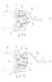
도 1은 본 발명의 일 실시예에 따른 문신바늘 구동장치를 나타낸 예시도이다.
도 2는 도 1의 분리 예시도이다.
도 3은 도 2의 모터 및 지지대를 분리해서 나타낸 예시도이다.
도 4는 도 3의 지지대 및 동력전달유닛을 분리해서 나타낸 예시도이다.
도 5는 도 4의 동력전달유닛을 분리해서 나타낸 예시도이다.
도 6은 본 발명에 따른 동력전달유닛의 작동을 설명하기 위한 예시도이다.FIG. 1 is an exemplary diagram showing a tattoo needle driving device according to one embodiment of the present invention.
Figure 2 is a separation example of Figure 1.
Figure 3 is an example diagram showing the motor and support of Figure 2 separated.
Figure 4 is an example diagram showing the support and power transmission unit of Figure 3 separated.
Figure 5 is an example diagram showing the power transmission unit of Figure 4 in isolation.
Figure 6 is an exemplary diagram for explaining the operation of a power transmission unit according to the present invention.
이하 상술한 해결하고자 하는 과제가 구체적으로 실현될 수 있는 본 발명의 바람직한 실시예들이 첨부된 도면을 참조하여 설명된다. 본 실시예들을 설명함에 있어서, 동일 구성에 대해서는 동일 명칭 및 동일 부호가 사용될 수 있으며 이에 따른 부가적인 설명은 생략될 수 있다.Hereinafter, preferred embodiments of the present invention, in which the above-described problems to be solved can be specifically realized, are described with reference to the attached drawings. In describing these embodiments, the same names and symbols may be used for the same components, and additional descriptions thereof may be omitted.
먼저 본 실시예에 따른 문신장치는 시술자가 손으로 쉽게 파지한 상태에서 신체에 대해 문신 작업을 용이하게 수행할 수 있도록 팬슬과 같은 형태를 취한다. 이러한 문신장치는 모터로부터 전달되는 회전 구동력을 이용하여 문신바늘을 직선 왕복 운동시키면서 피부에 상처를 만들고 상처 부위에 문신 물감을 채워가면서 피부에 문신을 새기게 된다.First, the tattoo device according to the present embodiment takes the form of a pencil so that the practitioner can easily perform tattoo work on the body while holding it with his or her hand. This tattoo device uses a rotary driving force transmitted from a motor to move a tattoo needle back and forth in a straight line, thereby creating a wound on the skin and filling the wounded area with tattoo pigment to tattoo the skin.
도 1은 본 발명의 일 실시예에 따른 문신바늘 구동장치를 나타낸 예시도이고, 도 2는 도 1의 분리 예시도이다.FIG. 1 is an exemplary diagram showing a tattoo needle driving device according to one embodiment of the present invention, and FIG. 2 is an exemplary diagram showing a separation of FIG. 1.
본 발명의 실시예에 따른 문신장치는 기본적으로 도시 생략된 문신바늘을 직선 왕복 동작시키기 위한 구동력을 제공하는 문신바늘 구동장치(100) 및 문신바늘 카트리지(미도시)를 포함할 수 있다.A tattoo device according to an embodiment of the present invention may basically include a tattoo needle drive device (100) that provides a driving force for making a tattoo needle (not shown) move in a straight line and a tattoo needle cartridge (not shown).
도시 생략된 문신바늘 카트리지는 사용 여부에 따라 문신바늘 구동장치(100)에 탈부착 가능하게 결합되는 카트리지 형태를 이루는 것으로, 카트리지 본체와, 카트리지 본체에 수직축선(VA)을 따라 왕복 이동이 가능하게 결합되는 문신바늘과, 문신바늘과 동일한 수직축선(VA)을 따라 연장되는 구동축을 포함할 수 있다. 구동축은 문신바늘과 일체로 형성될 수도 있다. 그리고, 문신바늘 카트리지는 문신바늘의 구동축을 상부 방향으로 탄성 지지하는 탄성부재를 더 포함할 수 있다. 탄성부재에 의해 탄성 지지된 문신바늘의 구동축은 후술되는 가압대(220)에 밀착될 수 있다.The tattoo needle cartridge, which is omitted in the city, is in the form of a cartridge that is detachably coupled to a tattoo needle drive device (100) depending on whether it is used, and may include a cartridge body, a tattoo needle coupled to the cartridge body so as to be reciprocally movable along a vertical axis (VA), and a drive shaft that extends along the same vertical axis (VA) as the tattoo needle. The drive shaft may be formed integrally with the tattoo needle. In addition, the tattoo needle cartridge may further include an elastic member that elastically supports the drive shaft of the tattoo needle in an upward direction. The drive shaft of the tattoo needle elastically supported by the elastic member may be in close contact with a pressure member (220) described below.
문신바늘 구동장치(100)는 커버, 지지대(110), 모터(120), 동력전달유닛(200)을 포함할 수 있다.The tattoo needle drive device (100) may include a cover, a support (110), a motor (120), and a power transmission unit (200).
커버는 문신바늘 구동장치(100)의 외형을 형상하는 것으로, 상부커버(101), 중간커버(103) 및 하부커버(102)를 포함할 수 있다.The cover forms the outer shape of the tattoo needle drive device (100) and may include an upper cover (101), a middle cover (103), and a lower cover (102).
상부커버(101)는 문신바늘 구동장치(100)의 상부 외형을 형성하며, 지지대(110) 및 모터(120)를 감싸도록 마련될 수 있다. 도시되진 않은 모터(120)의 상측에 마련되는 내부 공간에는 배터리 등이 추가 장착될 수 있다.The upper cover (101) forms the upper outer shape of the tattoo needle drive device (100) and may be provided to surround the support (110) and the motor (120). A battery or the like may be additionally installed in the internal space provided on the upper side of the motor (120), which is not shown.
중간커버(103)는 상단부가 상부커버(101)의 하단부에 탈부착 가능하게 결합될 수 있으며, 동력전달유닛(200)을 감싸도록 마련될 수 있다. 그리고, 중간커버(103)는 내부에 수직가이드를 가질 수 있다. 수직가이드는 수직축선(VA)을 따라 연장될 수 있으며, 후술되는 가압대(220)의 수직가압부(223)가 수직축선(VA)을 따라 이동하도록 안내할 수 있다.The middle cover (103) may be detachably connected at the upper end to the lower end of the upper cover (101) and may be arranged to surround the power transmission unit (200). In addition, the middle cover (103) may have a vertical guide inside. The vertical guide may extend along the vertical axis (VA) and guide the vertical pressurizing portion (223) of the pressurizing member (220) described below to move along the vertical axis (VA).
하부커버(102)는 문신바늘 구동장치(100)의 하부 외형을 형성하며, 중간커버(103)를 감싸도록 마련될 수 있고, 중간커버(103)에 탈부착이 가능하게 결합될 수 있다. 그리고, 하부커버(102)의 하단부에는 도시 생략된 문신바늘 카트리지가 탈부착 가능하게 결합될 수 있다. 문신바늘 카트리지가 하부커버(102)에 삽입 결합되면 문신바늘의 구동축은 가압대(220)의 수직가압부(223)에 자동적으로 밀착될 수 있다.The lower cover (102) forms the lower outer shape of the tattoo needle drive device (100), and may be provided to cover the middle cover (103), and may be detachably coupled to the middle cover (103). In addition, a tattoo needle cartridge, not shown, may be detachably coupled to the lower end of the lower cover (102). When the tattoo needle cartridge is inserted and coupled to the lower cover (102), the driving shaft of the tattoo needle may automatically be brought into close contact with the vertical pressurizing portion (223) of the pressurizing unit (220).
상부커버(101) 및 하부커버(102)는 시술자가 용이하게 파지할 수 있도록 외측면은 다각형상으로 형성될 수 있다.The outer surfaces of the upper cover (101) and the lower cover (102) can be formed in a polygonal shape so that the operator can easily grasp them.
지지대(110)는 모터(120) 및 동력전달유닛(200)을 지지할 수 있다.The support (110) can support the motor (120) and the power transmission unit (200).
모터(120)는 회전축(121: 도 3 참조)이 문신바늘의 구동축과 동일한 수직축선(VA) 상에 배치되며, 수직축선(VA)을 따라 하부 방향을 향하도록 배치될 수 있다.The motor (120) may be positioned on the same vertical axis (VA) as the driving axis of the tattoo needle with the rotation axis (121: see FIG. 3) and may be positioned so as to face downward along the vertical axis (VA).
동력전달유닛(200)은 모터(120)의 회전축(121)과 문신바늘의 구동축을 연결하며, 회전축(121)의 회전 운동을 변환하여 구동축이 직선 왕복 이동되도록 할 수 있다.The power transmission unit (200) connects the rotation shaft (121) of the motor (120) and the drive shaft of the tattoo needle, and can convert the rotational motion of the rotation shaft (121) to allow the drive shaft to move in a linear reciprocating manner.
본 실시예에 따른 동력전달유닛(200)은 모터(120)의 회전축(121) 및 문신바늘의 구동축에 대한 편심 구조를 배제하고, 모터(120)의 회전축(121) 및 문신바늘의 구동축과 동일한 수직축선(VA)을 가지도록 구성된다. 이에 따라, 회전축(121)에서 출력되는 회전력을 직선 왕복 운동으로 변환하여 문신바늘의 직선 왕복 동작이 정확히 구현되도록 할 수 있고, 문신장치의 소형화가 가능하며, 특히 진동 및 소음 발생을 크게 감소할 수 있다.The power transmission unit (200) according to the present embodiment excludes an eccentric structure with respect to the rotational shaft (121) of the motor (120) and the driving shaft of the tattoo needle, and is configured to have the same vertical axis (VA) as the rotational shaft (121) of the motor (120) and the driving shaft of the tattoo needle. Accordingly, the rotational force output from the rotational shaft (121) can be converted into a linear reciprocating motion so that the linear reciprocating motion of the tattoo needle can be accurately implemented, and the miniaturization of the tattoo device is possible, and in particular, vibration and noise generation can be greatly reduced.
이하, 본 실시예에 따른 문신바늘 구동장치(100)의 동력전달유닛(200)을 중심으로 보다 상세히 설명한다.Hereinafter, the power transmission unit (200) of the tattoo needle driving device (100) according to the present embodiment will be described in more detail.
도 3은 도 2의 모터 및 지지대를 분리해서 나타낸 예시도이고, 도 4는 도 3의 지지대 및 동력전달유닛을 분리해서 나타낸 예시도이며, 도 5는 도 4의 동력전달유닛을 분리해서 나타낸 예시도이고, 도 6은 본 발명에 따른 동력전달유닛의 작동을 설명하기 위한 예시도이다.FIG. 3 is an exemplary diagram showing the motor and support of FIG. 2 separated, FIG. 4 is an exemplary diagram showing the support and power transmission unit of FIG. 3 separated, FIG. 5 is an exemplary diagram showing the power transmission unit of FIG. 4 separated, and FIG. 6 is an exemplary diagram explaining the operation of the power transmission unit according to the present invention.
지지대(110)는 지지대 본체(111) 및 지지대 연장부(112)를 포함할 수 있다.The support (110) may include a support body (111) and a support extension (112).
지지대 본체(111)는 모터(120)의 회전축(121)를 하부로 관통시킨 상태로 모터(120)를 지지할 수 있다. 그리고, 지지대 본체(111)는 상부커버(101)에 고정 결합될 수 있다.The support body (111) can support the motor (120) with the rotation shaft (121) of the motor (120) penetrating downward. In addition, the support body (111) can be fixedly connected to the upper cover (101).
지지대 연장부(112)는 지지대 본체(111)에서 하부 방향으로 연장되며, 내부에 설치 공간을 가지는 원통체 형상으로 형성될 수 있다. 내부 설치 공간에는 동력전달유닛(200)이 배치될 수 있다. 지지대 연장부(112)는 수직축선(VA) 방향으로 연장되는 수직슬롯을 가질 수 있다.The support extension (112) extends downward from the support main body (111) and may be formed in a cylindrical shape having an installation space inside. A power transmission unit (200) may be placed in the internal installation space. The support extension (112) may have a vertical slot extending in the direction of the vertical axis (VA).
수직슬롯은 제1수직슬롯(112a)을 가질 수 있다. 제1수직슬롯(112a)은 지지대 연장부(112)의 일측에 형성될 수 있다. 제1수직슬롯(112a)은 회동부재(230)의 제1회동암(232)과 결합되는 가압대(220)의 수직축선(VA) 방향으로의 이동을 안내할 수 있다.The vertical slot may have a first vertical slot (112a). The first vertical slot (112a) may be formed on one side of the support extension (112). The first vertical slot (112a) may guide movement of the pressure member (220) coupled with the first rotation arm (232) of the rotation member (230) in the direction of the vertical axis (VA).
수직슬롯은 제2수직슬롯(112b)을 더 가질 수 있다. 제2수직슬롯(112b)은 지지대 연장부(112)의 타측에 형성될 수 있다. 제2수직슬롯(112b)은 회동부재(230)의 제2회동암(233)의 수직축선(VA) 방향으로의 이동을 안내할 수 있다. 이러한 제2수직슬롯(112b) 및 제2회동암(233)에 의해 회동부재(230)는 축연장부(210)의 회전에 연동하되 회전은 제한되고 수직축선(VA) 방향으로의 변위만이 발생하게 된다.The vertical slot may further have a second vertical slot (112b). The second vertical slot (112b) may be formed on the other side of the support extension (112). The second vertical slot (112b) may guide movement of the second rotation arm (233) of the rotational member (230) in the direction of the vertical axis (VA). By the second vertical slot (112b) and the second rotation arm (233), the rotational member (230) is linked to the rotation of the shaft extension (210), but the rotation is limited and only displacement in the direction of the vertical axis (VA) occurs.
본 실시예에 따른 동력전달유닛(200)은 축연장부(210), 가압대(220), 회동부재(230)를 포함할 수 있다.The power transmission unit (200) according to the present embodiment may include an extension member (210), a pressurizing member (220), and a rotating member (230).
축연장부(210)는 모터(120)의 회전축(121)에 결합되어 회전축(121)과 연동하여 회전할 수 있다. 그리고, 축연장부(210)는 수직축선(VA)에 대해 경사진 경사축선(IA)을 따라 연장하여 형성된다. 즉, 축연장부(210)는 회전축(121)과 연동하여 수직축선(VA)을 중심으로 회전하는 중 수직축선(VA) 및 경사축선(IA)이 이루는 경사각(a)을 유지할 수 있다.The shaft extension part (210) is coupled to the rotation shaft (121) of the motor (120) and can rotate in conjunction with the rotation shaft (121). In addition, the shaft extension part (210) is formed by extending along an inclined axis line (IA) inclined with respect to the vertical axis line (VA). That is, the shaft extension part (210) can maintain an inclination angle (a) formed by the vertical axis line (VA) and the inclined axis line (IA) while rotating around the vertical axis line (VA) in conjunction with the rotation shaft (121).
축연장부(210)는 마운트(211) 및 축부재(213)를 가질 수 있다.The shaft extension part (210) may have a mount (211) and a shaft member (213).
마운트(211)는 축연장부(210)의 상부를 형성되며, 상면에는 회전축(121)이 결합되는 축공이 형성된다. 마운트(211)의 축공에 결합된 회전축(121)은 마운트(211)를 관통하여 나사 결합되는 체결구(212)에 의해 고정될 수 있다. 물론 축연장부(210)는 마운트(211) 없이 모터(120)의 회전축(121)에 직결될 수도 있다.The mount (211) forms the upper part of the shaft extension part (210), and an axial hole is formed on the upper surface to which a rotation shaft (121) is coupled. The rotation shaft (121) coupled to the axial hole of the mount (211) can be fixed by a fastener (212) that penetrates the mount (211) and is screw-coupled. Of course, the shaft extension part (210) can also be directly connected to the rotation shaft (121) of the motor (120) without the mount (211).
축부재(213)는 축연장부(210)의 하부를 형성하며, 수직축선(VA)에 대해 경사진 경사축선(IA)을 따라 연장하여 형성될 수 있다. 축부재(213)는 하단부에 베어링의 설치 위치를 제한하기 위한 플랜지를 가질 수 있고, 축부재(213)에 베어링(240)을 설치한 후 고정구를 이용해서 플랜지를 축부재(213)에 고정 결합할 수 있다.The shaft member (213) forms the lower part of the shaft extension part (210) and can be formed by extending along an inclined axis line (IA) inclined with respect to the vertical axis line (VA). The shaft member (213) can have a flange for limiting the installation position of the bearing at the lower part, and after installing the bearing (240) on the shaft member (213), the flange can be fixedly connected to the shaft member (213) using a fixing member.
가압대(220)는 문신바늘 카트리지의 문신바늘의 구동축에 결합될 수 있으며, 수직축선(VA)을 따라 이동하도록 마련될 수 있다.The pressurizing member (220) may be coupled to the driving shaft of the tattoo needle of the tattoo needle cartridge and may be arranged to move along the vertical axis (VA).
가압대(220)는 암결합부(221), 경사연결부(225), 수직가압부(223)를 가질 수 있다.The pressurizing member (220) may have a female connecting member (221), an inclined connecting member (225), and a vertical pressurizing member (223).
암결합부(221)는 지지대 연장부(112)를 사이에 두고 축연장부(210)의 일측에 배치될 수 있고, 링부재(231)의 제1회동암(232)이 결합될 수 있다. 이때, 제1회동암(232) 및 암결합부(221)는 볼 조인트 결합 구조를 가질 수 있다. 즉, 제1회동암(232)의 단부에는 구 형상의 볼부재가 마련되고, 암결합부(221)에는 볼부재가 삽입 결합되는 결합홈이 마련될 수 있다. 이에 따라, 제1회동암(232)의 수직축선(VA) 방향으로의 변위로부터 가압대(220)의 수직 이동이 안정적으로 보장될 수 있다.The female coupling part (221) can be arranged on one side of the axial extension part (210) with the support extension part (112) in between, and the first rotary arm (232) of the ring member (231) can be coupled. At this time, the first rotary arm (232) and the female coupling part (221) can have a ball joint coupling structure. That is, a spherical ball member can be provided at the end of the first rotary arm (232), and a coupling groove into which the ball member is inserted and coupled can be provided in the female coupling part (221). Accordingly, the vertical movement of the pressurizing member (220) can be stably guaranteed from the displacement of the first rotary arm (232) in the direction of the vertical axis (VA).
수직가압부(223)는 수직축선(VA)을 따라 연장하여 형성될 수 있고, 하단부가 문신바늘의 구동축에 결합될 수 있다. 앞서 설명한 바와 같이, 수직가압부(223) 및 문신바늘의 구동축은 밀착된 상태를 유지할 수 있는데, 이 경우 문신바늘의 구동축은 탄성부재에 의해 상부 방향으로 탄성 지지되도록 구성될 수 있다.The vertical pressurizing portion (223) may be formed by extending along the vertical axis (VA), and the lower end may be coupled to the driving shaft of the tattoo needle. As described above, the vertical pressurizing portion (223) and the driving shaft of the tattoo needle may be maintained in a close state, and in this case, the driving shaft of the tattoo needle may be configured to be elastically supported in an upward direction by an elastic member.
경사연결부(225)는 암결합부(221)의 하단부 및 수직가압부(223)의 상단부를 경사지게 연결할 수 있다.The inclined connection part (225) can connect the lower part of the female connection part (221) and the upper part of the vertical pressure part (223) in an inclined manner.
회동부재(230)는 축연장부의 회전과 연동하면서 발생되는 수직축선(VA) 방향의 변위로부터 문신바늘의 구동축이 직선 왕복 이동되도록 할 수 있다. 구체적으로, 회동부재(230)는 축연장부(210) 및 가압대(220)를 연결하며, 축연장부(210)의 회전 운동으로부터 가압대(220)를 수직축선(VA) 상에서 직선 왕복 이동시킬 수 있고, 이에 따라, 문신바늘의 구동축을 직선 왕복 이동시킬 수 있다.The rotating member (230) can cause the driving shaft of the tattoo needle to move linearly and reciprocally from the displacement in the direction of the vertical axis (VA) that occurs in conjunction with the rotation of the axial extension unit. Specifically, the rotating member (230) connects the axial extension unit (210) and the pressurizing member (220), and can cause the pressurizing member (220) to move linearly and reciprocally along the vertical axis (VA) from the rotational movement of the axial extension unit (210), thereby causing the driving shaft of the tattoo needle to move linearly and reciprocally.
회동부재(230)는 링부재(231), 제1회동암(232), 제2회동암(233)을 가질 수 있다.The rotating member (230) may have a ring member (231), a first rotating arm (232), and a second rotating arm (233).
링부재(231)는 축연장부(210)를 감싸도록 링 형상으로 마련될 수 있고, 축연장부(210)의 외주면에 대해 회전 가능하게 결합될 수 있다.The ring member (231) can be provided in a ring shape to surround the axial extension part (210) and can be rotatably coupled to the outer circumference of the axial extension part (210).
제1회동암(232)은 링부재(231)의 외면 일측에서 경사축선(IA)을 교차하는(실질적으로 수직하는) 방향으로 돌출 형성될 수 있다. 제1회동암(232)은 가압대(220)의 암결합부(221)에 결합될 수 있다. 가압대(220)의 암결합부(221)는 제1수직슬롯(112a)에 의해 수직축선(VA) 방향으로의 이동이 안내될 수 있다.The first rotation arm (232) may be formed to protrude in a direction intersecting (substantially perpendicular to) the inclined axis line (IA) on one side of the outer surface of the ring member (231). The first rotation arm (232) may be coupled to the female coupling part (221) of the pressure member (220). The female coupling part (221) of the pressure member (220) may be guided to move in the direction of the vertical axis line (VA) by the first vertical slot (112a).
제2회동암(233)은 링부재(231)의 외면 타측에서 경사축선(IA)을 교차하는(실질적으로 수직하는) 방향으로 돌출 형성될 수 있다. 제2회동암(233)은 제2수직슬롯(112b)에 의해 수직축선(VA) 방향으로의 이동이 안내될 수 있다.The second pivot arm (233) can be formed to protrude in a direction intersecting (substantially perpendicular to) the inclined axis line (IA) on the other side of the outer surface of the ring member (231). The second pivot arm (233) can be guided to move in the direction of the vertical axis line (VA) by the second vertical slot (112b).
이에 따라, 축연장부(210)가 회전하면 회동부재(230)는 제2회동암(233)이 제2수직슬롯(112b)에 구속되어 회전되지 않고 수직축선(VA) 방향으로 변위가 발생된다. 그러면 제1회동암(232)에 결합되어 있는 가압대(220) 역시 연동하여 수직축선(VA) 방향으로 직선 왕복 이동하면서 문신바늘의 구동축을 직선 왕복 이동시킬 수 있다.Accordingly, when the shaft extension part (210) rotates, the rotational member (230) is not rotated because the second rotational arm (233) is restrained by the second vertical slot (112b) and is displaced in the direction of the vertical axis (VA). Then, the pressure plate (220) coupled to the first rotational arm (232) can also move linearly and reciprocally in the direction of the vertical axis (VA) while interlocking to linearly reciprocate the driving shaft of the tattoo needle.
한편, 동력전달유닛(200)은 베어링(240)을 더 가질 수 있다.Meanwhile, the power transmission unit (200) may have additional bearings (240).
베어링(240)은 축연장부(210)의 축부재(213)의 외주면과 회동부재(230)의 링부재(231)의 내주면 사이에 배치될 수 있고, 축부재(213)로부터 링부재(231)의 안정적인 회전을 안내할 수 있다. 베어링(240)은 기본적으로 복수의 볼을 매개로 연결되는 내륜 및 외륜으로 구성될 수 있으며, 내륜은 축부재(213)에 결합될 수 있고, 외륜은 링부재(231)에 결합될 수 있다.A bearing (240) can be arranged between the outer surface of the shaft member (213) of the shaft extension (210) and the inner surface of the ring member (231) of the rotating member (230), and can guide stable rotation of the ring member (231) from the shaft member (213). The bearing (240) can be basically composed of an inner ring and an outer ring connected via a plurality of balls, and the inner ring can be coupled to the shaft member (213), and the outer ring can be coupled to the ring member (231).
동력전달유닛(200)의 작동을 보충 설명하면 다음과 같다.The operation of the power transmission unit (200) is further described as follows.
모터(120)의 회전축(121)이 회전하면, 축연장부(210)는 회전축(121)과 연동하여 수직축선(VA)을 중심으로 회전하고, 축연장부(210)의 경사축선(IA)은 수직축선(VA)에 대해 경사각(a)을 유지하게 된다.When the rotation shaft (121) of the motor (120) rotates, the shaft extension (210) rotates around the vertical axis (VA) in conjunction with the rotation shaft (121), and the inclination axis (IA) of the shaft extension (210) maintains an inclination angle (a) with respect to the vertical axis (VA).
이때, 회동부재(230)의 제2회동암(233)이 제2수직슬롯(112b)에 구속되어 있기 때문에, 축연장부(210)의 회전에 연동하는 회동부재(230)의 회전은 제한되고 수직축선(VA) 방향으로의 변위가 발생된다. 이에 따라, 회동부재(230)의 제1회동암(232)에 결합되어 있는 가압대(220)가 수직축선(VA) 방향으로 직선 왕복 이동되고, 결과적으로, 문신바늘의 구동축을 수직축선(VA) 방향으로 직선 왕복 이동시키게 된다.At this time, since the second rotation arm (233) of the rotation member (230) is restrained to the second vertical slot (112b), the rotation of the rotation member (230) linked to the rotation of the axial extension part (210) is restricted and displacement in the direction of the vertical axis (VA) occurs. Accordingly, the pressure plate (220) coupled to the first rotation arm (232) of the rotation member (230) moves linearly and reciprocally in the direction of the vertical axis (VA), and as a result, the driving shaft of the tattoo needle is linearly and reciprocally moved in the direction of the vertical axis (VA).
이처럼 본 발명은 모터(120)의 회전축(121) 및 문신바늘의 구동축을 동축 상태로 배치하고, 축연장부(210), 회동부재(230) 및 가압대(220)의 회전 및 동작 범위가 수직축선(VA)에서 크게 벗어나지 않도록 설계하여, 문신장치의 작동의 품질을 높일 수 있고, 작동 중 진동이나 소음을 크게 줄일 수 있다. 그리고, 동력전달유닛(200)인 축연장부(210), 회동부재(230) 및 가압대(220)의 배치 위치 및 동작 범위가 모터(120)를 지지하는 지지대(110)의 반경 범위 내 수직축선(VA) 상에 배치 가능하므로 문신장치의 콤팩트하고 유연한 설계가 가능하다.In this way, the present invention arranges the rotational shaft (121) of the motor (120) and the driving shaft of the tattoo needle in a coaxial state, and designs the rotation and operating ranges of the shaft extension (210), the rotating member (230), and the pressurizing member (220) not to greatly deviate from the vertical axis (VA), thereby improving the operating quality of the tattooing device and significantly reducing vibration and noise during operation. In addition, since the arrangement position and operating range of the shaft extension (210), the rotating member (230), and the pressurizing member (220), which are the power transmission unit (200), can be arranged on the vertical axis (VA) within the radius range of the support (110) that supports the motor (120), compact and flexible design of the tattooing device is possible.
상술한 바와 같이 도면을 참조하여 본 발명의 바람직한 실시예를 설명하였지만, 해당 기술 분야의 숙련된 당업자라면, 하기의 청구범위에 기재된 본 발명의 사상 및 영역으로부터 벗어나지 않는 범위 내에서 본 발명을 다양하게 수정 또는 변경시킬 수 있다.Although the preferred embodiments of the present invention have been described with reference to the drawings as described above, it will be apparent to those skilled in the art that various modifications or changes may be made to the present invention without departing from the spirit and scope of the present invention as set forth in the claims below.
100: 문신바늘 구동장치
110: 지지대
112a: 제1수직슬롯
112b: 제2수직슬롯
120: 모터
200: 동력전달유닛
210: 축연장부
220: 가압대
230: 회동부재
231: 링부재
232: 제1회동암
233: 제2회동암100: Tattoo Needle Drive Device
110: Support
112a: 1st vertical slot
112b: 2nd vertical slot
120: Motor
200: Power transmission unit
210: Extension of the shaft
220: Pressurized
230: Absence of rotation
231: Ring Absence
232: The first round of Dongam
233: The 2nd Dongam
Claims (5)
Translated fromKorean상기 지지대에 설치되는 모터; 및
상기 지지대에 설치되며, 상기 모터의 회전축과 문신바늘의 구동축을 연결하며, 상기 회전축의 회전 운동을 변환하여 상기 구동축이 직선 왕복 이동되도록 하는 동력전달유닛을 포함하고,
상기 회전축 및 상기 구동축은 동일한 수직축선을 가지며,
상기 동력전달유닛은,
상기 회전축에 결합되며, 상기 수직축선에 대해 경사진 경사축선을 따라 연장되는 축연장부와,
상기 축연장부의 외주면에 회전 가능하게 결합되는 링부재와, 상기 링부재의 외면 일측에서 상기 경사축선을 교차하는 방향으로 돌출되는 제1회동암을 가지며, 상기 축연장부의 회전과 연동하면서 발생되는 상기 제1회동암의 수직축선 방향의 변위로부터 상기 구동축이 직선 왕복 이동되도록 하는 회동부재와,
상기 수직축선을 따라 이동 가능하게 마련되며, 일단부는 상기 제1회동암에 결합되고, 타단부는 상기 구동축에 결합되는 가압대를 포함하고,
상기 가압대는, 상단부가 상기 제1회동암이 결합되는 암결합부와, 하단부가 상기 구동축에 결합되고 상기 수직축선 방향으로 연장되는 수직가압부와, 상기 암결합부의 하단부 및 상기 수직가압부의 상단부를 연결하는 경사연결부를 포함하는 것을 특징으로 하는 문신바늘 구동장치.Support;
a motor installed on the above support; and
It is installed on the above support, and includes a power transmission unit that connects the rotational shaft of the motor and the drive shaft of the tattoo needle, and converts the rotational motion of the rotational shaft so that the drive shaft moves linearly back and forth.
The above rotational axis and the above driving axis have the same vertical axis line,
The above power transmission unit,
An axial extension portion coupled to the above rotational axis and extending along an inclined axis line inclined with respect to the vertical axis line,
A ring member rotatably coupled to the outer surface of the above-mentioned axial member, and a first rotary arm protruding from one side of the outer surface of the above-mentioned ring member in a direction intersecting the above-mentioned inclined axis line, and a rotary member that causes the driving shaft to move in a linear reciprocating manner from displacement of the first rotary arm in the direction of the vertical axis line that occurs in conjunction with the rotation of the above-mentioned axial member,
It includes a pressure plate that is arranged to be movable along the vertical axis, one end of which is connected to the first rotary arm, and the other end of which is connected to the driving shaft.
A tattoo needle drive device characterized in that the pressurizing member includes a female coupling portion to which the first rotary arm is coupled at an upper end, a vertical pressurizing portion having a lower end coupled to the driving shaft and extending in the direction of the vertical axis, and an inclined connecting portion connecting the lower end of the female coupling portion and the upper end of the vertical pressurizing portion.
상기 회동부재는,
상기 링부재의 외면 타측에서 상기 경사축선을 교차하는 방향으로 돌출되는 제2회동암을 더 포함하고,
상기 지지대는,
상기 제2회동암이 상기 수직축선을 따라 이동되도록 안내하는 수직슬롯을 포함하는 것을 특징으로 하는 문신바늘 구동장치.In the first paragraph,
The above rotating member is,
It further includes a second rotating arm protruding in a direction intersecting the inclined axis line from the outer surface of the ring member.
The above support is,
A tattoo needle drive device characterized by including a vertical slot for guiding the second rotary arm to move along the vertical axis.
Priority Applications (1)
| Application Number | Priority Date | Filing Date | Title |
|---|---|---|---|
| KR1020230152986AKR102814585B1 (en) | 2023-11-07 | 2023-11-07 | Tattoo needles driving apparatus |
Applications Claiming Priority (1)
| Application Number | Priority Date | Filing Date | Title |
|---|---|---|---|
| KR1020230152986AKR102814585B1 (en) | 2023-11-07 | 2023-11-07 | Tattoo needles driving apparatus |
Publications (2)
| Publication Number | Publication Date |
|---|---|
| KR20250066895A KR20250066895A (en) | 2025-05-14 |
| KR102814585B1true KR102814585B1 (en) | 2025-05-30 |
Family
ID=95710383
Family Applications (1)
| Application Number | Title | Priority Date | Filing Date |
|---|---|---|---|
| KR1020230152986AActiveKR102814585B1 (en) | 2023-11-07 | 2023-11-07 | Tattoo needles driving apparatus |
Country Status (1)
| Country | Link |
|---|---|
| KR (1) | KR102814585B1 (en) |
Citations (1)
| Publication number | Priority date | Publication date | Assignee | Title |
|---|---|---|---|---|
| KR101593617B1 (en) | 2015-11-10 | 2016-02-12 | 권승열 | Needle machine |
Family Cites Families (5)
| Publication number | Priority date | Publication date | Assignee | Title |
|---|---|---|---|---|
| KR101150777B1 (en)* | 2009-07-22 | 2012-06-08 | 봄텍전자 주식회사 | Tatooing Apparatus |
| KR101466880B1 (en)* | 2013-02-28 | 2014-12-01 | (주)우리메카 | Mechanical skin resurfacing device |
| KR20170123756A (en)* | 2016-04-29 | 2017-11-09 | 봄텍전자 주식회사 | Tattooing apparatus |
| KR102042176B1 (en)* | 2017-07-06 | 2019-11-07 | 주식회사 미로 | Tattooing Apparatus |
| KR102372435B1 (en) | 2021-09-29 | 2022-05-30 | 주식회사 크롭 | Tattoo apparatus |
- 2023
- 2023-11-07KRKR1020230152986Apatent/KR102814585B1/enactiveActive
Patent Citations (1)
| Publication number | Priority date | Publication date | Assignee | Title |
|---|---|---|---|---|
| KR101593617B1 (en) | 2015-11-10 | 2016-02-12 | 권승열 | Needle machine |
Also Published As
| Publication number | Publication date |
|---|---|
| KR20250066895A (en) | 2025-05-14 |
Similar Documents
| Publication | Publication Date | Title |
|---|---|---|
| US20080033469A1 (en) | Blood withdrawal system | |
| US10369341B2 (en) | Micro needle driving device | |
| KR20070026151A (en) | Motor Drive for Ultrasonic Transducer Mechanically Scanned | |
| KR102814585B1 (en) | Tattoo needles driving apparatus | |
| US20170105702A1 (en) | Ultrasonic probe | |
| KR20120092546A (en) | Dental tool displacement apparatus and method with slow rotational motion | |
| JP5116021B2 (en) | Stepping actuator | |
| CN109975971A (en) | The locking of endoscope power holds mirror system with regulating mechanism and endoscope | |
| KR20240140667A (en) | Cartridge for moving focal point of ultrasound and treatment device using ultrasound comprising the same | |
| KR101209232B1 (en) | Needle Device | |
| CN108243626B (en) | Needle tube advancing and retreating assembly and winding machine | |
| US20200324098A1 (en) | Drive system and drive module for a hand-held device for locally piercing of human or animal skin, and hand-held device | |
| RU2644698C1 (en) | Tattoo machine and self-aligning support of tattoo machine motor shaft | |
| CN101987220A (en) | Needle driving assembly for medical instrument | |
| CN111053576A (en) | Transmission device for enabling ultrasonic three-dimensional probe transducer to rotate in reciprocating mode and application method thereof | |
| KR101766836B1 (en) | Small sized servo linear actuator including combination type outer-housing | |
| KR100946174B1 (en) | Reciprocating Power Unit | |
| US20220290347A1 (en) | Driving device used in sewing apparatus | |
| CN209906995U (en) | Sewing machine | |
| US11339858B2 (en) | Actuator for a needle | |
| CN221358183U (en) | Tattooing needle driving mechanism and tattooing machine | |
| KR200350253Y1 (en) | Device for marking with ink | |
| KR101484589B1 (en) | Needle apparatus | |
| CN222383689U (en) | Flexible rotary device of bending | |
| CN222787861U (en) | Rotary joint and surgical robot |
Legal Events
| Date | Code | Title | Description |
|---|---|---|---|
| PA0109 | Patent application | Patent event code:PA01091R01D Comment text:Patent Application Patent event date:20231107 | |
| PA0201 | Request for examination | Patent event code:PA02011R01I Patent event date:20231107 Comment text:Patent Application | |
| PA0302 | Request for accelerated examination | Patent event date:20231113 Patent event code:PA03022R01D Comment text:Request for Accelerated Examination | |
| PE0902 | Notice of grounds for rejection | Comment text:Notification of reason for refusal Patent event date:20240729 Patent event code:PE09021S01D | |
| PE0701 | Decision of registration | Patent event code:PE07011S01D Comment text:Decision to Grant Registration Patent event date:20250226 | |
| PG1501 | Laying open of application | ||
| GRNT | Written decision to grant | ||
| PR0701 | Registration of establishment | Comment text:Registration of Establishment Patent event date:20250526 Patent event code:PR07011E01D | |
| PR1002 | Payment of registration fee | Payment date:20250526 End annual number:3 Start annual number:1 | |
| PG1601 | Publication of registration |