KR102811191B1 - Apparatus and method for estmating direction in wireless communication system - Google Patents
Apparatus and method for estmating direction in wireless communication systemDownload PDFInfo
- Publication number
- KR102811191B1 KR102811191B1KR1020180169807AKR20180169807AKR102811191B1KR 102811191 B1KR102811191 B1KR 102811191B1KR 1020180169807 AKR1020180169807 AKR 1020180169807AKR 20180169807 AKR20180169807 AKR 20180169807AKR 102811191 B1KR102811191 B1KR 102811191B1
- Authority
- KR
- South Korea
- Prior art keywords
- auxiliary
- beams
- pair
- vehicle
- communication
- Prior art date
- Legal status (The legal status is an assumption and is not a legal conclusion. Google has not performed a legal analysis and makes no representation as to the accuracy of the status listed.)
- Active
Links
Images


Classifications
- H—ELECTRICITY
- H04—ELECTRIC COMMUNICATION TECHNIQUE
- H04B—TRANSMISSION
- H04B7/00—Radio transmission systems, i.e. using radiation field
- H04B7/02—Diversity systems; Multi-antenna system, i.e. transmission or reception using multiple antennas
- H04B7/04—Diversity systems; Multi-antenna system, i.e. transmission or reception using multiple antennas using two or more spaced independent antennas
- H04B7/0408—Diversity systems; Multi-antenna system, i.e. transmission or reception using multiple antennas using two or more spaced independent antennas using two or more beams, i.e. beam diversity
- H—ELECTRICITY
- H04—ELECTRIC COMMUNICATION TECHNIQUE
- H04B—TRANSMISSION
- H04B7/00—Radio transmission systems, i.e. using radiation field
- H04B7/02—Diversity systems; Multi-antenna system, i.e. transmission or reception using multiple antennas
- H04B7/04—Diversity systems; Multi-antenna system, i.e. transmission or reception using multiple antennas using two or more spaced independent antennas
- H04B7/06—Diversity systems; Multi-antenna system, i.e. transmission or reception using multiple antennas using two or more spaced independent antennas at the transmitting station
- H04B7/0613—Diversity systems; Multi-antenna system, i.e. transmission or reception using multiple antennas using two or more spaced independent antennas at the transmitting station using simultaneous transmission
- H04B7/0615—Diversity systems; Multi-antenna system, i.e. transmission or reception using multiple antennas using two or more spaced independent antennas at the transmitting station using simultaneous transmission of weighted versions of same signal
- H04B7/0617—Diversity systems; Multi-antenna system, i.e. transmission or reception using multiple antennas using two or more spaced independent antennas at the transmitting station using simultaneous transmission of weighted versions of same signal for beam forming
- H—ELECTRICITY
- H04—ELECTRIC COMMUNICATION TECHNIQUE
- H04B—TRANSMISSION
- H04B7/00—Radio transmission systems, i.e. using radiation field
- H04B7/02—Diversity systems; Multi-antenna system, i.e. transmission or reception using multiple antennas
- H04B7/04—Diversity systems; Multi-antenna system, i.e. transmission or reception using multiple antennas using two or more spaced independent antennas
- H04B7/06—Diversity systems; Multi-antenna system, i.e. transmission or reception using multiple antennas using two or more spaced independent antennas at the transmitting station
- H04B7/0613—Diversity systems; Multi-antenna system, i.e. transmission or reception using multiple antennas using two or more spaced independent antennas at the transmitting station using simultaneous transmission
- H04B7/0615—Diversity systems; Multi-antenna system, i.e. transmission or reception using multiple antennas using two or more spaced independent antennas at the transmitting station using simultaneous transmission of weighted versions of same signal
- H04B7/0619—Diversity systems; Multi-antenna system, i.e. transmission or reception using multiple antennas using two or more spaced independent antennas at the transmitting station using simultaneous transmission of weighted versions of same signal using feedback from receiving side
- H04B7/0621—Feedback content
- H04B7/0626—Channel coefficients, e.g. channel state information [CSI]
- H—ELECTRICITY
- H04—ELECTRIC COMMUNICATION TECHNIQUE
- H04B—TRANSMISSION
- H04B7/00—Radio transmission systems, i.e. using radiation field
- H04B7/02—Diversity systems; Multi-antenna system, i.e. transmission or reception using multiple antennas
- H04B7/04—Diversity systems; Multi-antenna system, i.e. transmission or reception using multiple antennas using two or more spaced independent antennas
- H04B7/06—Diversity systems; Multi-antenna system, i.e. transmission or reception using multiple antennas using two or more spaced independent antennas at the transmitting station
- H04B7/0613—Diversity systems; Multi-antenna system, i.e. transmission or reception using multiple antennas using two or more spaced independent antennas at the transmitting station using simultaneous transmission
- H04B7/0615—Diversity systems; Multi-antenna system, i.e. transmission or reception using multiple antennas using two or more spaced independent antennas at the transmitting station using simultaneous transmission of weighted versions of same signal
- H04B7/0619—Diversity systems; Multi-antenna system, i.e. transmission or reception using multiple antennas using two or more spaced independent antennas at the transmitting station using simultaneous transmission of weighted versions of same signal using feedback from receiving side
- H04B7/0621—Feedback content
- H04B7/0632—Channel quality parameters, e.g. channel quality indicator [CQI]
- H—ELECTRICITY
- H04—ELECTRIC COMMUNICATION TECHNIQUE
- H04B—TRANSMISSION
- H04B7/00—Radio transmission systems, i.e. using radiation field
- H04B7/02—Diversity systems; Multi-antenna system, i.e. transmission or reception using multiple antennas
- H04B7/04—Diversity systems; Multi-antenna system, i.e. transmission or reception using multiple antennas using two or more spaced independent antennas
- H04B7/06—Diversity systems; Multi-antenna system, i.e. transmission or reception using multiple antennas using two or more spaced independent antennas at the transmitting station
- H04B7/0613—Diversity systems; Multi-antenna system, i.e. transmission or reception using multiple antennas using two or more spaced independent antennas at the transmitting station using simultaneous transmission
- H04B7/0615—Diversity systems; Multi-antenna system, i.e. transmission or reception using multiple antennas using two or more spaced independent antennas at the transmitting station using simultaneous transmission of weighted versions of same signal
- H04B7/0619—Diversity systems; Multi-antenna system, i.e. transmission or reception using multiple antennas using two or more spaced independent antennas at the transmitting station using simultaneous transmission of weighted versions of same signal using feedback from receiving side
- H04B7/0636—Feedback format
- H04B7/0639—Using selective indices, e.g. of a codebook, e.g. pre-distortion matrix index [PMI] or for beam selection
- H—ELECTRICITY
- H04—ELECTRIC COMMUNICATION TECHNIQUE
- H04B—TRANSMISSION
- H04B7/00—Radio transmission systems, i.e. using radiation field
- H04B7/02—Diversity systems; Multi-antenna system, i.e. transmission or reception using multiple antennas
- H04B7/04—Diversity systems; Multi-antenna system, i.e. transmission or reception using multiple antennas using two or more spaced independent antennas
- H04B7/06—Diversity systems; Multi-antenna system, i.e. transmission or reception using multiple antennas using two or more spaced independent antennas at the transmitting station
- H04B7/0686—Hybrid systems, i.e. switching and simultaneous transmission
- H04B7/0691—Hybrid systems, i.e. switching and simultaneous transmission using subgroups of transmit antennas
- H—ELECTRICITY
- H04—ELECTRIC COMMUNICATION TECHNIQUE
- H04B—TRANSMISSION
- H04B7/00—Radio transmission systems, i.e. using radiation field
- H04B7/02—Diversity systems; Multi-antenna system, i.e. transmission or reception using multiple antennas
- H04B7/04—Diversity systems; Multi-antenna system, i.e. transmission or reception using multiple antennas using two or more spaced independent antennas
- H04B7/06—Diversity systems; Multi-antenna system, i.e. transmission or reception using multiple antennas using two or more spaced independent antennas at the transmitting station
- H04B7/0686—Hybrid systems, i.e. switching and simultaneous transmission
- H04B7/0695—Hybrid systems, i.e. switching and simultaneous transmission using beam selection
- H04B7/06952—Selecting one or more beams from a plurality of beams, e.g. beam training, management or sweeping
- H04B7/0696—Determining beam pairs
- H—ELECTRICITY
- H04—ELECTRIC COMMUNICATION TECHNIQUE
- H04L—TRANSMISSION OF DIGITAL INFORMATION, e.g. TELEGRAPHIC COMMUNICATION
- H04L5/00—Arrangements affording multiple use of the transmission path
- H04L5/003—Arrangements for allocating sub-channels of the transmission path
- H04L5/0048—Allocation of pilot signals, i.e. of signals known to the receiver
- H—ELECTRICITY
- H04—ELECTRIC COMMUNICATION TECHNIQUE
- H04L—TRANSMISSION OF DIGITAL INFORMATION, e.g. TELEGRAPHIC COMMUNICATION
- H04L27/00—Modulated-carrier systems
- H04L27/26—Systems using multi-frequency codes
- H04L27/2601—Multicarrier modulation systems
- H04L27/2602—Signal structure
- H04L27/261—Details of reference signals
- H04L27/2613—Structure of the reference signals
Landscapes
- Engineering & Computer Science (AREA)
- Signal Processing (AREA)
- Computer Networks & Wireless Communication (AREA)
- Physics & Mathematics (AREA)
- Mathematical Physics (AREA)
- Radio Transmission System (AREA)
- Mobile Radio Communication Systems (AREA)
Abstract
Translated fromKoreanDescription
Translated fromKorean본 개시(disclosure)는 일반적으로 무선 통신 시스템에 관한 것으로, 보다 구체적으로 무선 통신 시스템에서 방향을 추정하기 위한 장치 및 방법에 관한 것이다.The present disclosure relates generally to wireless communication systems, and more specifically to devices and methods for estimating direction in a wireless communication system.
4G(4th generation) 통신 시스템 상용화 이후 증가 추세에 있는 무선 데이터 트래픽 수요를 충족시키기 위해, 개선된 5G(5th generation) 통신 시스템 또는 pre-5G 통신 시스템을 개발하기 위한 노력이 이루어지고 있다. 이러한 이유로, 5G 통신 시스템 또는 pre-5G 통신 시스템은 4G 네트워크 이후(Beyond 4G Network) 통신 시스템 또는 LTE(Long Term Evolution) 시스템 이후(Post LTE) 시스템이라 불리어지고 있다.In order to meet the increasing demand for wireless data traffic since the commercialization of 4G (4th generation) communication systems, efforts are being made to develop improved 5G (5th generation) communication systems or pre-5G communication systems. For this reason, 5G communication systems or pre-5G communication systems are also called Beyond 4G Network communication systems or Post LTE (Long Term Evolution) system.
높은 데이터 전송률을 달성하기 위해, 5G 통신 시스템은 초고주파(mmWave) 대역(예를 들어, 60기가(60GHz) 대역과 같은)에서의 구현이 고려되고 있다. 초고주파 대역에서의 전파의 경로손실 완화 및 전파의 전달 거리를 증가시키기 위해, 5G 통신 시스템에서는 빔포밍(beamforming), 거대 배열 다중 입출력(massive MIMO), 전차원 다중입출력(Full Dimensional MIMO, FD-MIMO), 어레이 안테나(array antenna), 아날로그 빔형성(analog beam-forming), 및 대규모 안테나(large scale antenna) 기술들이 논의되고 있다.To achieve high data rates, 5G communication systems are being considered for implementation in ultra-high frequency (mmWave) bands (e.g., 60 gigahertz (GHz) bands). To mitigate radio path loss and increase the transmission range of radio waves in ultra-high frequency bands, beamforming, massive MIMO, full-dimensional MIMO (FD-MIMO), array antenna, analog beam-forming, and large scale antenna technologies are being discussed in 5G communication systems.
또한 시스템의 네트워크 개선을 위해, 5G 통신 시스템에서는 진화된 소형 셀, 개선된 소형 셀(advanced small cell), 클라우드 무선 액세스 네트워크(cloud radio access network, cloud RAN), 초고밀도 네트워크(ultra-dense network), 기기 간 통신(Device to Device communication, D2D), 무선 백홀(wireless backhaul), 이동 네트워크(moving network), 협력 통신(cooperative communication), CoMP(Coordinated Multi-Points), 및 수신 간섭제거(interference cancellation) 등의 기술 개발이 이루어지고 있다.In addition, to improve the network of the system, the 5G communication system is developing technologies such as evolved small cells, advanced small cells, cloud radio access networks (cloud RAN), ultra-dense networks, device to device communication (D2D), wireless backhaul, moving networks, cooperative communication, CoMP (Coordinated Multi-Points), and interference cancellation.
이 밖에도, 5G 시스템에서는 진보된 코딩 변조(Advanced Coding Modulation, ACM) 방식인 FQAM(Hybrid Frequency Shift Keying and Quadrature Amplitude Modulation) 및 SWSC(Sliding Window Superposition Coding)과, 진보된 접속 기술인 FBMC(Filter Bank Multi Carrier), NOMA(Non Orthogonal Multiple Access), 및 SCMA(Sparse Code Multiple Access) 등이 개발되고 있다.In addition, advanced coding modulation (ACM) methods such as Hybrid Frequency Shift Keying and Quadrature Amplitude Modulation (FQAM) and Sliding Window Superposition Coding (SWSC), as well as advanced access technologies such as Filter Bank Multi Carrier (FBMC), Non Orthogonal Multiple Access (NOMA), and Sparse Code Multiple Access (SCMA), are being developed in 5G systems.
5G 통신 시스템은, 초고주파 대역(예: mmWave)의 특성으로 인한 경로 손실의 문제를 극복하기 위해, 빔포밍 기법을 이용하여 신호 이득을 높이도록 운용되고 있다. 원활한 빔포밍 통신을 위해 송신 혹은 수신되는 신호의 방향을 보다 정확히 파악할 것이 요구된다. 한편, 단순히 많은 빔들을 이용하여 방향 추정의 정확도를 높이는 경우, 방향을 파악하기 위해 소요되는 시간이 증가할 수 있다.5G communication systems are operated to increase signal gain by using beamforming techniques to overcome the problem of path loss due to the characteristics of ultra-high frequency bands (e.g., mmWave). For smooth beamforming communication, it is required to more accurately identify the direction of the transmitted or received signal. On the other hand, if the accuracy of direction estimation is simply increased by using many beams, the time required to identify the direction may increase.
상술한 바와 같은 논의를 바탕으로, 본 개시(disclosure)는, 무선 통신 시스템에서 송신 혹은 수신되는 신호의 방향을 보다 정확히 추정하기 위한 장치 및 방법을 제공한다.Based on the discussion as described above, the present disclosure provides a device and method for more accurately estimating the direction of a signal transmitted or received in a wireless communication system.
또한, 본 개시는, 무선 통신 시스템에서 낮은 오버헤드(overhead)로 신호의 방향을 추정하기 위한 장치 및 방법을 제공한다.Additionally, the present disclosure provides a device and method for estimating the direction of a signal with low overhead in a wireless communication system.
본 개시의 다양한 실시 예들에 따르면, 무선 통신 시스템에서 제1 장치는 안테나 어레이(antenna array), 적어도 하나의 송수신기, 및 적어도 하나의 프로세서를 포함하고, 상기 적어도 하나의 송수신기는, 빔 셋(beam set)을 이용하여 신호들을 송신하고, 제2 장치로부터, 상기 빔 셋 중 적어도 하나의 빔을 가리키기 위한 신호를 수신하고, 상기 적어도 하나의 프로세서는, 상기 적어도 하나의 빔에 기반하여, 보조 빔 페어를 결정하고, 상기 적어도 하나의 송수신기는, 상기 보조 빔 페어(auxiliary beam pair)를 이용하여 기준 신호들을 상기 제2 장치에게 송신하고, 상기 제2 장치로부터, 상기 보조 빔 페어에 대한 피드백 정보를 수신하고, 상기 적어도 하나의 프로세서는, 상기 피드백 정보에 기반하여, 상기 제2 장치와 관련된 통신 방향을 결정하도록 구성될 수 있다.According to various embodiments of the present disclosure, in a wireless communication system, a first device may include an antenna array, at least one transceiver, and at least one processor, wherein the at least one transceiver is configured to transmit signals using a beam set and receive a signal from a second device for indicating at least one beam of the beam set, the at least one processor may determine an auxiliary beam pair based on the at least one beam, the at least one transceiver may transmit reference signals to the second device using the auxiliary beam pair and receive feedback information about the auxiliary beam pair from the second device, and the at least one processor may be configured to determine a communication direction related to the second device based on the feedback information.
본 개시의 다양한 실시 예들에 따르면, 무선 통신 시스템에서 무선 통신 시스템에서, 제1 장치의 동작 방법은, 빔 셋을 이용하여 신호들을 송신하는 과정과, 제2 장치로부터, 상기 빔 셋 중 적어도 하나의 빔을 가리키기 위한 신호를 수신하는 과정과, 상기 적어도 하나의 빔에 기반하여, 보조 빔 페어를 결정하는 과정과, 상기 보조 빔 페어를 이용하여 기준 신호들을 상기 제2 장치에게 송신하는 과정과, 상기 제2 장치로부터, 상기 보조 빔 페어에 대한 피드백 정보를 수신하는 과정과, 상기 피드백 정보에 기반하여, 상기 제2 장치와 관련된 통신 방향을 결정하는 과정을 포함할 수 있다.According to various embodiments of the present disclosure, in a wireless communication system, a method of operating a first device may include the steps of: transmitting signals using a beam set; receiving a signal from a second device for indicating at least one beam of the beam set; determining an auxiliary beam pair based on the at least one beam; transmitting reference signals to the second device using the auxiliary beam pair; receiving feedback information about the auxiliary beam pair from the second device; and determining a communication direction related to the second device based on the feedback information.
본 개시의 다양한 실시 예들에 따른 장치 및 방법은, 원활한 빔포밍 통신을 위해 요구되는, 신호의 통신 방향을 보다 정확히 결정할 수 있게 한다.Devices and methods according to various embodiments of the present disclosure enable more accurately determining the communication direction of a signal, which is required for smooth beamforming communication.
본 개시의 다양한 실시 예들에 따른 장치 및 방법은, 보조 빔 페어를 이용함으로써, 빔 훈련으로 인한 오버헤드를 줄이면서 방향을 추정할 수 있게 한다.Devices and methods according to various embodiments of the present disclosure enable direction estimation while reducing overhead due to beam training by utilizing an auxiliary beam pair.
본 개시에서 얻을 수 있는 효과는 이상에서 언급한 효과들로 제한되지 않으며, 언급하지 않은 또 다른 효과들은 아래의 기재로부터 본 개시가 속하는 기술 분야에서 통상의 지식을 가진 자에게 명확하게 이해될 수 있을 것이다.The effects obtainable from the present disclosure are not limited to the effects mentioned above, and other effects not mentioned will be clearly understood by a person skilled in the art to which the present disclosure belongs from the description below.
도 1은 본 개시의 다양한 실시 예들에 따른 무선 통신 시스템을 도시한다.
도 2는 본 개시의 다양한 실시 예들에 따른 무선 통신 시스템에서 기지국의 구성을 도시한다.
도 3은 본 개시의 다양한 실시 예들에 따른 무선 통신 시스템에서 단말의 구성을 도시한다.
도 4a 내지 4c는 본 개시의 다양한 실시 예들에 따른 무선 통신 시스템에서 통신부의 구성을 도시한다.
도 5는 본 개시의 다양한 실시 예들에 따른, 방향 추정(direction estimation)을 위한 제1 장치의 동작 흐름을 도시한다.
도 6은 본 개시의 다양한 실시 예들에 따른, 방향 추정의 예를 도시한다.
도 7은 본 개시의 다양한 실시 예들에 따른, 빔 셋(beam set)을 결정하기 위한 제1 장치의 동작 흐름을 도시한다.
도 8은 본 개시의 다양한 실시 예들에 따른, 빔 폭(beamwidth)의 예를 도시한다.
도 9는 본 개시의 다양한 실시 예들에 따른, 보조 빔 페어(auxiliary beam pair)를 결정하기 위한 제1 장치의 동작 흐름을 도시한다.
도 10은 본 개시의 다양한 실시 예들에 따른, 보조 빔 페어의 예를 도시한다.
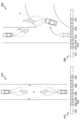
도 11은 본 개시의 다양한 실시 예들에 따른 차량 간 통신에서 방향 추정의 예를 도시한다.
도 12a는 본 개시의 다양한 실시 예들에 따른 차량 간 통신에서 방향 추적(direction tracking)의 예를 도시한다.
도 12b는 본 개시의 다양한 실시 예들에 따른 차량 간 통신에서 주행 방향 변경에 따른 방향 추적의 예를 도시한다.
도 12c는 본 개시의 다양한 실시 예들에 따른 차량 간 통신에서 기준 방향 변경에 따른 방향 추정의 예를 도시한다.
도 13a 내지 13b는 본 개시의 다양한 실시 예들에 따른 빔 폭의 성능을 나타내는 그래프를 도시한다.
도 14a 내지 14d는 본 개시의 다양한 실시 예들에 따른, 2-단계 각도 추정 기법에 따른 방향 추정의 성능을 나타내는 그래프를 도시한다.FIG. 1 illustrates a wireless communication system according to various embodiments of the present disclosure.
FIG. 2 illustrates a configuration of a base station in a wireless communication system according to various embodiments of the present disclosure.
FIG. 3 illustrates a configuration of a terminal in a wireless communication system according to various embodiments of the present disclosure.
FIGS. 4A to 4C illustrate the configuration of a communication unit in a wireless communication system according to various embodiments of the present disclosure.
FIG. 5 illustrates an operation flow of a first device for direction estimation according to various embodiments of the present disclosure.
FIG. 6 illustrates an example of direction estimation according to various embodiments of the present disclosure.
FIG. 7 illustrates an operational flow of a first device for determining a beam set according to various embodiments of the present disclosure.
FIG. 8 illustrates examples of beamwidths according to various embodiments of the present disclosure.
FIG. 9 illustrates an operational flow of a first device for determining an auxiliary beam pair according to various embodiments of the present disclosure.
FIG. 10 illustrates an example of an auxiliary beam pair according to various embodiments of the present disclosure.
FIG. 11 illustrates an example of direction estimation in vehicle-to-vehicle communication according to various embodiments of the present disclosure.
FIG. 12a illustrates an example of direction tracking in vehicle-to-vehicle communication according to various embodiments of the present disclosure.
FIG. 12b illustrates an example of direction tracking according to a change in driving direction in vehicle-to-vehicle communication according to various embodiments of the present disclosure.
FIG. 12c illustrates an example of direction estimation according to a change in reference direction in vehicle-to-vehicle communication according to various embodiments of the present disclosure.
FIGS. 13a to 13b illustrate graphs showing beam width performance according to various embodiments of the present disclosure.
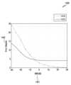
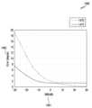
FIGS. 14a to 14d illustrate graphs showing the performance of direction estimation according to a two-step angle estimation technique according to various embodiments of the present disclosure.
본 개시에서 사용되는 용어들은 단지 특정한 실시 예를 설명하기 위해 사용된 것으로, 다른 실시 예의 범위를 한정하려는 의도가 아닐 수 있다. 단수의 표현은 문맥상 명백하게 다르게 뜻하지 않는 한, 복수의 표현을 포함할 수 있다. 기술적이거나 과학적인 용어를 포함해서 여기서 사용되는 용어들은 본 개시에 기재된 기술 분야에서 통상의 지식을 가진 자에 의해 일반적으로 이해되는 것과 동일한 의미를 가질 수 있다. 본 개시에 사용된 용어들 중 일반적인 사전에 정의된 용어들은, 관련 기술의 문맥상 가지는 의미와 동일 또는 유사한 의미로 해석될 수 있으며, 본 개시에서 명백하게 정의되지 않는 한, 이상적이거나 과도하게 형식적인 의미로 해석되지 않는다. 경우에 따라서, 본 개시에서 정의된 용어일지라도 본 개시의 실시 예들을 배제하도록 해석될 수 없다.The terms used in this disclosure are only used to describe specific embodiments and may not be intended to limit the scope of other embodiments. The singular expression may include the plural expression unless the context clearly indicates otherwise. The terms used herein, including technical or scientific terms, may have the same meaning as commonly understood by a person having ordinary skill in the art described in this disclosure. Among the terms used in this disclosure, terms defined in general dictionaries may be interpreted as having the same or similar meaning as the meaning they have in the context of the related technology, and shall not be interpreted in an ideal or excessively formal meaning unless explicitly defined in this disclosure. In some cases, even if a term is defined in this disclosure, it cannot be interpreted to exclude embodiments of the present disclosure.
이하에서 설명되는 본 개시의 다양한 실시 예들에서는 하드웨어적인 접근 방법을 예시로서 설명한다. 하지만, 본 개시의 다양한 실시 예들에서는 하드웨어와 소프트웨어를 모두 사용하는 기술을 포함하고 있으므로, 본 개시의 다양한 실시 예들이 소프트웨어 기반의 접근 방법을 제외하는 것은 아니다.In the various embodiments of the present disclosure described below, a hardware-based approach is described as an example. However, since the various embodiments of the present disclosure include techniques using both hardware and software, the various embodiments of the present disclosure do not exclude a software-based approach.
이하 본 개시는 무선 통신 시스템에서 신호의 통신 방향을 보다 정확하게 추정하기 위한 장치 및 방법에 관한 것이다. 구체적으로, 본 개시는 무선 통신 시스템에서 빔포밍 기법을 활용하여, 원활한 통신을 위해 요구되는 신호의 방향에 대한 정보를 획득하기 위한 기술을 설명한다.The present disclosure relates to a device and method for more accurately estimating the communication direction of a signal in a wireless communication system. Specifically, the present disclosure describes a technique for obtaining information on the direction of a signal required for smooth communication by utilizing a beamforming technique in a wireless communication system.
이하 설명에서 사용되는 신호를 지칭하는 용어(예: 신호, 기준 신호, 정보), 통신 노드(communication node)들을 지칭하는 용어(예: 기지국, 단말, 차량, 전자 장치 등), 장치의 구성 요소를 지칭하는 용어 등은 설명의 편의를 위해 예시된 것이다. 따라서, 본 개시가 후술되는 용어들에 한정되는 것은 아니며, 동등한 기술적 의미를 가지는 다른 용어가 사용될 수 있다.In the following description, terms referring to signals (e.g., signal, reference signal, information), terms referring to communication nodes (e.g., base station, terminal, vehicle, electronic device, etc.), terms referring to components of a device, etc. are examples for convenience of explanation. Therefore, the present disclosure is not limited to the terms described below, and other terms having equivalent technical meanings may be used.
또한, 본 개시는, 일부 통신 규격(예: 3GPP(3rd Generation Partnership Project))에서 사용되는 용어들을 이용하여 다양한 실시 예들을 설명하지만, 이는 설명을 위한 예시일 뿐이다. 본 개시의 다양한 실시 예들은, 다른 통신 시스템에서도, 용이하게 변형되어 적용될 수 있다.In addition, although the present disclosure describes various embodiments using terms used in some communication standards (e.g., 3rd Generation Partnership Project (3GPP)), this is only an example for explanation. The various embodiments of the present disclosure can be easily modified and applied to other communication systems.
도 1은 본 개시의 다양한 실시 예들에 따른 무선 통신 시스템을 도시한다. 도 1은 무선 통신 시스템에서 무선 채널을 이용하는 노드(node)들의 일부로서, 기지국 110, 단말 120, 및 단말 130을 예시한다.FIG. 1 illustrates a wireless communication system according to various embodiments of the present disclosure. FIG. 1 exemplifies a
기지국 110은 단말들 120, 130에게 무선 접속을 제공하는 네트워크 인프라스트럭쳐(infrastructure)이다. 기지국 110은 신호를 송신할 수 있는 거리에 기초하여 일정한 지리적 영역으로 정의되는 커버리지(coverage)를 가진다. 기지국 110은 기지국(base station) 외에 '액세스 포인트(access point, AP)', '이노드비(eNodeB, eNB)', '5G 노드(5th generation node)', '무선 포인트(wireless point)' 또는 이와 동등한 기술적 의미를 가지는 다른 용어로 지칭될 수 있다. 다양한 실시 예들에 따라, 기지국 110은, 하나 이상의 '송수신 포인트(transmission/reception point, TRP)'와 연결될 수 있다. 기지국 110은 하나 이상의 TRP들을 통해, 단말 120 또는 단말 130에게 하향링크 신호를 전송하거나 상향링크 신호를 수신할 수 있다.The
단말 120 및 단말 130 각각은 사용자에 의해 사용되는 장치로서, 기지국 110과 무선 채널을 통해 통신을 수행한다. 경우에 따라, 단말 120 및 단말 130 중 적어도 하나는 사용자의 관여 없이 운영될 수 있다. 즉, 단말 120 및 단말 130 중 적어도 하나는 기계 타입 통신(machine type communication, MTC)을 수행하는 장치로서, 사용자에 의해 휴대되지 아니할 수 있다. 단말 120 및 단말 130 각각은 단말(terminal) 외 '사용자 장비(user equipment, UE)', '이동국(mobile station)', '가입자국(subscriber station)', ‘고객 댁내 장치’(customer premises equipment, CPE), '원격 단말(remote terminal)', '무선 단말(wireless terminal)', ‘전자 장치(electronic device)’, 또는 ‘차량(vehicle)용 단말’, '사용자 장치(user device)' 또는 이와 동등한 기술적 의미를 가지는 다른 용어로 지칭될 수 있다.Each of the
기지국 110, 단말 120, 단말 130은 밀리미터 파(mmWave) 대역(예: 28GHz, 30GHz, 38GHz, 60GHz)에서 무선 신호를 송신 및 수신할 수 있다. 이때, 채널 이득의 향상을 위해, 기지국 110, 단말 120, 단말 130은 빔포밍(beamforming)을 수행할 수 있다. 여기서, 빔포밍은 송신 빔포밍 및 수신 빔포밍을 포함할 수 있다. 즉, 기지국 110, 단말 120, 단말 130은 송신 신호 또는 수신 신호에 방향성(directivity)을 부여할 수 있다. 이를 위해, 기지국 110 및 단말들 120, 130은 빔 탐색(beam search) 또는 빔 관리(beam management) 절차를 통해 서빙(serving) 빔들 112, 113, 121, 131을 선택할 수 있다. 서빙 빔들 112, 113, 121, 131이 선택된 후, 이후 통신은 서빙 빔들 112, 113, 121, 131을 송신한 자원과 QCL(quasi co-located) 관계에 있는 자원을 통해 수행될 수 있다.The
제1 안테나 포트 상의 심볼을 전달한 채널의 광범위한(large-scale) 특성들이 제2 안테나 포트 상의 심볼을 전달한 채널로부터 추정될(inferred) 수 있다면, 제1 안테나 포트 및 제2 안테나 포트는 QCL 관계에 있다고 평가될 수 있다. 예를 들어, 광범위한 특성들은 지연 스프레드(delay spread), 도플러 스프레드(doppler spread), 도플러 쉬프트(doppler shift), 평균 이득(average gain), 평균 지연(average delay), 공간적 수신 파라미터(spatial receiver parameter) 중 적어도 하나를 포함할 수 있다.The first antenna port and the second antenna port may be evaluated to have a QCL relationship if large-scale characteristics of a channel carrying a symbol on the first antenna port can be inferred from a channel carrying a symbol on the second antenna port. For example, the large-scale characteristics may include at least one of delay spread, Doppler spread, Doppler shift, average gain, average delay, and a spatial receiver parameter.
기지국 110은 단말 120에게 빔을 이용하여 신호를 전송할 수 있다. 이 때, 전송되는 신호는 지향적인 특성을 가지므로, 원활한 빔포밍 통신을 위해서는 빔의 방향이 적절하게 설정될 것이 요구된다. 기지국 110은 단말 120과 관련된 방향을 추정하고, 추정된 방향에 대응하는 빔을 이용하여 신호를 전송할 수 있다. 단말 120과 관련된 방향이란, 단말 120을 위해 기지국 110의 신호가 전송되는 방향, 즉 신호가 출발되는 각도(angle of departure, AoD)를 의미하거나 단말 120의 신호가 수신되는 방향, 즉 신호가 도달되는 각도(angle of arrival, AoA)를 의미한다. 이하, 본 개시는 신호가 실제로 전송되는 통신 방향을 보다 정확하게 추정함으로써, 통신 효율을 높이기 위한 방안에 대해 서술한다.The
도 1을 통해 빔포밍이 운용되는 시스템으로서 기지국과 단말 간 통신을 예로 서술하였으나, 본 개시의 다양한 실시 예들은 이에 한정되지 않는다. 본 개시의 방향 추정 기법은, D2D(device to device), V2X(vehicle to everything) 등을 포함하는 사이드 링크(sidelink)에 적용될 수 있다.Although the communication between a base station and a terminal is described as an example of a system in which beamforming is operated through Fig. 1, various embodiments of the present disclosure are not limited thereto. The direction estimation technique of the present disclosure can be applied to sidelinks including D2D (device to device), V2X (vehicle to everything), etc.
송신기 및/또는 수신에게 복수의 안테나들을 사용하는 다중 입출력(multiple-input multiple output: MIMO) 시스템에서, 채널에 대한 정보를 획득하는 것은 MIMO 기술의 장점을 활용하기 위해서 매우 중요하게 여겨지고 활발히 연구되고 있다. 특히, MIMO 기술이 적용되는 빔포밍 통신 시스템에서는, 신호의 전송 방향 혹은 수신 방향(이하, 통신 방향), 다시 말해 송신 신호의 각도(angle-of-departure: AoD)와 수신 신호의 각도(angle-of-arrival: AoA)를 보다 정확히 추정(estimation)할 것이 요구된다.In a multiple-input multiple output (MIMO) system that uses multiple antennas for a transmitter and/or a receiver, obtaining information about the channel is considered very important and is being actively studied in order to utilize the advantages of MIMO technology. In particular, in a beamforming communication system to which MIMO technology is applied, it is required to more accurately estimate the transmission direction or reception direction of a signal (hereinafter, communication direction), that is, the angle-of-departure (AoD) of the transmitted signal and the angle-of-arrival (AoA) of the received signal.
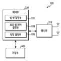
도 2는 본 개시의 다양한 실시 예들에 따른 무선 통신 시스템에서 기지국의 구성을 도시한다. 도 2에 예시된 구성은 기지국 110의 구성으로서 이해될 수 있다. 이하 사용되는 '...부', '...기' 등의 용어는 적어도 하나의 기능이나 동작을 처리하는 단위를 의미하며, 이는 하드웨어나 소프트웨어, 또는, 하드웨어 및 소프트웨어의 결합으로 구현될 수 있다.FIG. 2 illustrates a configuration of a base station in a wireless communication system according to various embodiments of the present disclosure. The configuration illustrated in FIG. 2 can be understood as a configuration of
도 2를 참고하면, 기지국 110은 무선통신부 210, 백홀통신부 220, 저장부 230, 제어부 240를 포함한다.Referring to FIG. 2, the
무선통신부 210은 무선 채널을 통해 신호를 송수신하기 위한 기능들을 수행한다. 예를 들어, 무선통신부 210은 시스템의 물리 계층 규격에 따라 기저대역 신호 및 비트열 간 변환 기능을 수행한다. 예를 들어, 데이터 송신 시, 무선통신부 210은 송신 비트열을 부호화 및 변조함으로써 복소 심벌들을 생성한다. 또한, 데이터 수신 시, 무선통신부 210은 기저대역 신호를 복조 및 복호화를 통해 수신 비트열을 복원한다. 또한, 무선통신부 210은 기저대역 신호를 RF(radio frequency) 대역 신호로 상향변환한 후 안테나를 통해 송신하고, 안테나를 통해 수신되는 RF 대역 신호를 기저대역 신호로 하향변환한다.The
이를 위해, 무선통신부 210은 송신 필터, 수신 필터, 증폭기, 믹서(mixer), 오실레이터(oscillator), DAC(digital to analog convertor), ADC(analog to digital convertor) 등을 포함할 수 있다. 또한, 무선통신부 210은 다수의 송수신 경로(path)들을 포함할 수 있다. 나아가, 무선통신부 210은 다수의 안테나 요소들(antenna elements)로 구성된 적어도 하나의 안테나 어레이(antenna array)를 포함할 수 있다. 하드웨어의 측면에서, 무선통신부 210은 디지털 유닛(digital unit) 및 아날로그 유닛(analog unit)으로 구성될 수 있으며, 아날로그 유닛은 동작 전력, 동작 주파수 등에 따라 다수의 서브 유닛(sub-unit)들로 구성될 수 있다.To this end, the
무선통신부 210은 신호를 송수신할 수 있다. 예를 들어, 무선통신부 210은 동기 신호(synchronization signal), 기준 신호(reference signal), 시스템 정보, 메시지, 제어 정보, 또는 데이터 등을 전송할 수 있다. 또한, 무선통신부 210은 빔포밍을 수행할 수 있다. 무선통신부 210은, 송수신하고자 하는 신호에 제어부 240의 설정에 따른 방향성을 부여하기 위해, 신호에 빔포밍 가중치를 적용할 수 있다.The
무선통신부 210은 상술한 바와 같이 신호를 송신 및 수신한다. 이에 따라, 무선통신부 210의 전부 또는 일부는 '송신부', '수신부' 또는 '송수신부'로 지칭될 수 있다. 또한, 이하 설명에서, 무선 채널을 통해 수행되는 송신 및 수신은 무선통신부 210에 의해 상술한 바와 같은 처리가 수행되는 것을 포함하는 의미로 사용된다.The
백홀통신부 220은 네트워크 내 다른 노드들과 통신을 수행하기 위한 인터페이스를 제공한다. 즉, 백홀통신부 220은 기지국 110에서 다른 노드, 예를 들어, 다른 접속 노드, 다른 기지국, 상위 노드, 코어망 등으로 송신되는 비트열을 물리적 신호로 변환하고, 다른 노드로부터 수신되는 물리적 신호를 비트열로 변환한다.The
저장부 230은 기지국 110의 동작을 위한 기본 프로그램, 응용 프로그램, 설정 정보 등의 데이터를 저장한다. 저장부 230은 휘발성 메모리, 비휘발성 메모리 또는 휘발성 메모리와 비휘발성 메모리의 조합으로 구성될 수 있다. 그리고, 저장부 230은 제어부 240의 요청에 따라 저장된 데이터를 제공한다. 다양한 실시 예들에 따라, 저장부 230은 기지국 110에서 운용될 빔 셋(beam set)의 각 빔 또는 보조 빔 페어(auxiliary beam pair, ABP)의 각 빔에 대한 방향 정보(또는 각도 정보라고 지칭될 수도 있음)를 저장할 수 있다. 일 실시 예에 따라, 방향 정보는 어레이 응답 벡터(array response vector)의 형태로 표현될 수 있다.The
제어부 240은 기지국 110의 전반적인 동작들을 제어한다. 예를 들어, 제어부 240은 무선통신부 210을 통해 또는 백홀통신부 220을 통해 신호를 송신 및 수신한다. 또한, 제어부 240은 저장부 230에 데이터를 기록하고, 읽는다. 그리고, 제어부 240은 통신 규격에서 요구하는 프로토콜 스택(protocol stack)의 기능들을 수행할 수 있다. 이를 위해, 제어부 240은 적어도 하나의 프로세서(processor)를 포함할 수 있다.The
다양한 실시 예들에 따라, 제어부 240은 빔 셋 결정부 241, 보조 빔 페어 결정부 243, 방향 결정부 245를 포함할 수 있다. 빔 셋 결정부 241은 빔 훈련(beam training)을 수행하기 위한 빔 셋을 결정할 수 있다. 다양한 실시 예들에 따를 때, 빔 셋의 빔은 후술되는 보조 빔 페어의 빔보다 넓은 빔 폭을 가질 수 있다. 보조 빔 페어 결정부 243은, 방향을 보다 정확히 추정하기 위한 보조 빔 페어를 결정할 수 있다. 방향 결정부 245는, 보조 빔 페어의 빔들을 이용하여 전송되는 신호들에 대한 피드백 정보로부터, 신호의 방향, 즉 송신 각도 또는 수신 각도를 추정할 수 있다. 본 개시에서 방향을 추정하는 과정은, 안테나 어레이에 적용될 적합한 어레이 응답 벡터를 결정하는 과정을 포함할 수 있다. 빔 셋 결정부 241, 보조 빔 페어 결정부 243, 및 방향 결정부 245는 저장된 명령어 집합 또는 코드로서, 적어도 일시적으로 제어부 240에 상주된(resided) 명령어/코드 또는 명령어/코드를 저장한 저장 공간이거나, 제어부 240를 구성하는 회로(circuitry)의 일부, 또는 제어부 240의 기능을 수행하기 위한 모듈일 수 있다. 다양한 실시 예들에 따라, 제어부 240은 기지국 110이 후술하는 다양한 실시 예들에 따른 동작들을 수행하도록 제어할 수 있다.According to various embodiments, the
도 3은 본 개시의 다양한 실시 예들에 따른 무선 통신 시스템에서 단말의 구성을 도시한다. 도 3에 예시된 구성은 단말 120의 구성으로서 이해될 수 있다. 이하 사용되는 '...부', '...기' 등의 용어는 적어도 하나의 기능이나 동작을 처리하는 단위를 의미하며, 이는 하드웨어나 소프트웨어, 또는, 하드웨어 및 소프트웨어의 결합으로 구현될 수 있다.FIG. 3 illustrates a configuration of a terminal in a wireless communication system according to various embodiments of the present disclosure. The configuration illustrated in FIG. 3 can be understood as a configuration of
도 3을 참고하면, 단말 120은 통신부 310, 저장부 320, 제어부 330을 포함한다.Referring to FIG. 3,
통신부 310은 무선 채널을 통해 신호를 송수신하기 위한 기능들을 수행한다. 예를 들어, 통신부 310은 시스템의 물리 계층 규격에 따라 기저대역 신호 및 비트열 간 변환 기능을 수행한다. 예를 들어, 데이터 송신 시, 통신부 310은 송신 비트열을 부호화 및 변조함으로써 복소 심벌들을 생성한다. 또한, 데이터 수신 시, 통신부 310은 기저대역 신호를 복조 및 복호화를 통해 수신 비트열을 복원한다. 또한, 통신부 310은 기저대역 신호를 RF 대역 신호로 상향변환한 후 안테나를 통해 송신하고, 안테나를 통해 수신되는 RF 대역 신호를 기저대역 신호로 하향변환한다. 예를 들어, 통신부 310은 송신 필터, 수신 필터, 증폭기, 믹서, 오실레이터, DAC, ADC 등을 포함할 수 있다.The
또한, 통신부 310은 다수의 송수신 경로(path)들을 포함할 수 있다. 나아가, 통신부 310은 안테나부를 포함할 수 있다. 통신부 310은 다수의 안테나 요소들로 구성된 적어도 하나의 안테나 어레이를 포함할 수 있다. 하드웨어의 측면에서, 통신부 310은 디지털 회로 및 아날로그 회로(예: RFIC(radio frequency integrated circuit))로 구성될 수 있다. 여기서, 디지털 회로 및 아날로그 회로는 하나의 패키지로 구현될 수 있다. 또한, 통신부 310은 다수의 RF 체인들을 포함할 수 있다. 통신부 310은 빔포밍을 수행할 수 있다. 통신부 310은, 송수신하고자 하는 신호에 제어부 330의 설정에 따른 방향성을 부여하기 위해, 신호에 빔포밍 가중치를 적용할 수 있다. 일 실시 예에 따라, 통신부 310은 RF(radio frequency) 블록(또는 RF 부)을 포함할 수 있다. RF 블록은 안테나와 관련된 제1 RF 회로(circuitry)와 기저대역 프로세싱과 관련된 제2 RF 회로(circuitry)를 포함할 수 있다. 제1 RF 회로는 RF-A(antenna)로 지칭될 수 있다. 제2 RF 회로는 RF-B(baseband)로 지칭될 수 있다.In addition, the
또한, 통신부 310은 신호를 송수신할 수 있다. 통신부 310은 하향링크 신호를 수신할 수 있다. 하향링크 신호는 동기 신호(synchronization signal, SS), 기준 신호(reference signal, RS)(예: CRS(cell-specific reference signal), DM(demodulation)-RS), 시스템 정보(예: MIB, SIB, RMSI(remaining system information), OSI(other system information)), 설정 메시지(configuration message), 제어 정보(control information) 또는 하향링크 데이터 등을 포함할 수 있다. 또한, 통신부 310은 상향링크 신호를 전송할 수 있다. 상향링크 신호는 랜덤 액세스 관련 신호(예: 랜덤 액세스 프리앰블(random access preamble, RAP)(또는 Msg1(message 1)), Msg3(message 3)) 또는 기준 신호(예: SRS(sounding reference signal), DM-RS) 등을 포함할 수 있다. 또한, 통신부 310은 서로 다른 주파수 대역의 신호들을 처리하기 위해 서로 다른 통신 모듈들을 포함할 수 있다. 나아가, 통신부 310은 서로 다른 다수의 무선 접속 기술들을 지원하기 위해 다수의 통신 모듈들을 포함할 수 있다. 예를 들어, 서로 다른 무선 접속 기술들은 블루투스 저 에너지(bluetooth low energy, BLE), Wi-Fi(Wireless Fidelity), WiGig(WiFi Gigabyte), 셀룰러 망(예: LTE(Long Term Evolution), NR(new radio) 등을 포함할 수 있다. 또한, 서로 다른 주파수 대역들은 극고단파(super high frequency, SHF)(예: 2.5GHz, 5Ghz) 대역, mm파(millimeter wave)(예: 38GHz, 60GHz 등) 대역을 포함할 수 있다. 또한 통신부 310은 서로 다른 주파수 대역(예: LAA(licensed Assisted Access)를 위한 비면허 대역, CBRS(citizens broadband radio service)(예: 3.5 GHz)) 상에서 동일한 방식의 무선 접속 기술을 이용할 수도 있다.In addition, the
통신부 310은 상술한 바와 같이 신호를 송신 및 수신한다. 이에 따라, 통신부 310의 전부 또는 일부는 '송신부', '수신부' 또는 '송수신부'로 지칭될 수 있다. 또한, 이하 설명에서 무선 채널을 통해 수행되는 송신 및 수신은 통신부 310에 의해 상술한 바와 같은 처리가 수행되는 것을 포함하는 의미로 사용된다.The
저장부 320은 단말 120의 동작을 위한 기본 프로그램, 응용 프로그램, 설정 정보 등의 데이터를 저장한다. 저장부 320은 휘발성 메모리, 비휘발성 메모리 또는 휘발성 메모리와 비휘발성 메모리의 조합으로 구성될 수 있다. 그리고, 저장부 320은 제어부 330의 요청에 따라 저장된 데이터를 제공한다. 다양한 실시 예들에 따라, 저장부 320은 단말 120에서 운용될 빔 셋의 각 빔 또는 보조 빔 페어의 각 빔에 대한 방향 정보를 저장할 수 있다.The
제어부 330은 단말 120의 전반적인 동작들을 제어한다. 예를 들어, 제어부 330은 통신부 310를 통해 신호를 송신 및 수신한다. 또한, 제어부 330은 저장부 320에 데이터를 기록하고, 읽는다. 그리고, 제어부 330은 통신 규격에서 요구하는 프로토콜 스택의 기능들을 수행할 수 있다. 이를 위해, 제어부 330은 적어도 하나의 프로세서 또는 마이크로(micro) 프로세서를 포함하거나, 또는, 프로세서의 일부일 수 있다. 또한, 통신부 310의 일부 및 제어부 330은 CP라 지칭될 수 있다. 제어부 330은 통신을 수행하기 위한 다양한 모듈들을 포함할 수 있다.The
다양한 실시 예들에 따라, 제어부 330은 빔 셋 결정부 331, 보조 빔 페어 결정부 333, 및 방향 결정부 335를 포함할 수 있다. 빔 셋 결정부 331, 보조 빔 페어 결정부 333, 및 방향 결정부 335는 각각, 기지국 110의 빔 셋 결정부 241, 보조 빔 페어 결정부 243, 및 방향 결정부 245에 대응되므로, 중복되는 구성에 대한 구체적인 설명은 생략된다. 빔 셋 결정부 331, 보조 빔 페어 결정부 333, 및 방향 결정부 335는 저장부 320에 저장된 명령어 집합 또는 코드로서, 적어도 일시적으로 제어부 330에 상주된(resided) 명령어/코드 또는 명령어/코드를 저장한 저장 공간이거나, 제어부 330를 구성하는 회로(circuitry)의 일부, 또는 제어부 330의 기능을 수행하기 위한 모듈일 수 있다. 다양한 실시 예들에 따라, 제어부 330은 단말이 후술하는 다양한 실시 예들에 따른 동작들을 수행하도록 제어할 수 있다.According to various embodiments, the
도 3에 도시된 단말의 구성은, 단말의 일 예일 뿐, 도 3에 도시된 구성으로부터 한정되지 않는다. 즉, 다양한 실시 예들에 따라, 일부 구성이 추가, 삭제, 변경될 수 있다.The configuration of the terminal illustrated in FIG. 3 is only an example of the terminal and is not limited to the configuration illustrated in FIG. 3. That is, some configurations may be added, deleted, or changed according to various embodiments.
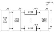
도 4a 내지 4c는 본 개시의 다양한 실시 예들에 따른 무선 통신 시스템에서 통신부의 구성을 도시한다. 도 4a 내지 4c는 도 2의 무선통신부 210 또는 도 3의 통신부 310의 상세한 구성에 대한 예를 도시한다. 구체적으로, 도 4a 내지 4c는 도 2의 무선통신부 210 또는 도 3의 통신부 310의 일부로서, 빔포밍을 수행하기 위한 구성요소들을 예시한다.FIGS. 4A to 4C illustrate a configuration of a communication unit in a wireless communication system according to various embodiments of the present disclosure. FIGS. 4A to 4C illustrate an example of a detailed configuration of the
도 4a를 참고하면, 무선통신부 210 또는 통신부 310은 부호화 및 변조부 402, 디지털 빔포밍부 404, 다수의 송신 경로들 406-1 내지 406-N, 아날로그 빔포밍부 408를 포함한다.Referring to FIG. 4A, the
부호화 및 변조부 402는 채널 인코딩을 수행한다. 채널 인코딩을 위해, LDPC(low density parity check) 코드, 컨볼루션(convolution) 코드, 폴라(polar) 코드 중 적어도 하나가 사용될 수 있다. 부호화 및 변조부 402는 성상도 맵핑(constellation mapping)을 수행함으로써 변조 심벌들을 생성한다.The encoding and
디지털 빔포밍부 404은 디지털 신호(예: 변조 심벌들)에 대한 빔포밍을 수행한다. 이를 위해, 디지털 빔포밍부 404은 변조 심벌들에 빔포밍 가중치들을 곱한다. 여기서, 빔포밍 가중치들은 신호의 크기 및 위상을 변경하기 위해 사용되며, '프리코딩 행렬(precoding matrix)', '프리코더(precoder)' 등으로 지칭될 수 있다. 디지털 빔포밍부 404는 다수의 송신 경로들 406-1 내지 406-N로 디지털 빔포밍된 변조 심벌들을 출력한다. 이때, MIMO(multiple input multiple output) 전송 기법에 따라, 변조 심벌들은 다중화되거나, 다수의 송신 경로들 406-1 내지 406-N로 동일한 변조 심벌들이 제공될 수 있다.The
다수의 송신 경로들 406-1 내지 406-N은 디지털 빔포밍된 디지털 신호들을 아날로그 신호로 변환한다. 이를 위해, 다수의 송신 경로들 406-1 내지 406-N 각각은 IFFT(inverse fast fourier transform) 연산부, CP(cyclic prefix) 삽입부, DAC, 상향 변환부를 포함할 수 있다. CP 삽입부는 OFDM(orthogonal frequency division multiplexing) 방식을 위한 것으로, 다른 물리 계층 방식(예: FBMC(filter bank multi-carrier))이 적용되는 경우 제외될 수 있다. 즉, 다수의 송신 경로들 406-1 내지 406-N은 디지털 빔포밍을 통해 생성된 다수의 스트림(stream)들에 대하여 독립된 신호처리 프로세스를 제공한다. 단, 구현 방식에 따라, 다수의 송신 경로들 406-1 내지 406-N의 구성요소들 중 일부는 공용으로 사용될 수 있다.The plurality of transmission paths 406-1 to 406-N convert digital beamformed digital signals into analog signals. To this end, each of the plurality of transmission paths 406-1 to 406-N may include an inverse fast fourier transform (IFFT) operation unit, a cyclic prefix (CP) insertion unit, a DAC, and an upconversion unit. The CP insertion unit is for an orthogonal frequency division multiplexing (OFDM) scheme and may be excluded when another physical layer scheme (e.g., filter bank multi-carrier (FBMC)) is applied. That is, the plurality of transmission paths 406-1 to 406-N provide independent signal processing processes for the plurality of streams generated through digital beamforming. However, depending on the implementation method, some of the components of the plurality of transmission paths 406-1 to 406-N may be used in common.
아날로그 빔포밍부 408는 아날로그 신호에 대한 빔포밍을 수행한다. 이를 위해, 디지털 빔포밍부 404은 아날로그 신호들에 빔포밍 가중치들을 곱한다. 여기서, 빔포밍 가중치들은 신호의 크기 및 위상을 변경하기 위해 사용된다. 구체적으로, 다수의 송신 경로들 406-1 내지 406-N 및 안테나들 간 연결 구조에 따라, 아날로그 빔포밍부 408는 도 4b 또는 도 4c와 같이 구성될 수 있다.The
도 4b를 참고하면, 아날로그 빔포밍부 408로 입력된 신호들은 위상/크기 변환, 증폭의 연산을 거쳐, 안테나들을 통해 송신된다. 이때, 각 경로의 신호는 서로 다른 안테나 집합들 즉, 안테나 어레이들을 통해 송신된다. 첫번째 경로를 통해 입력된 신호의 처리를 살펴보면, 신호는 위상/크기 변환부들 412-1-1 내지 412-1-M에 의해 서로 다른 또는 동일한 위상/크기를 가지는 신호열로 변환되고, 증폭기들 414-1-1 내지 414-1-M에 의해 증폭된 후, 안테나들을 통해 송신된다.Referring to FIG. 4b, signals input to the
도 4c를 참고하면, 아날로그 빔포밍부 408로 입력된 신호들은 위상/크기 변환, 증폭의 연산을 거쳐, 안테나들을 통해 송신된다. 이때, 각 경로의 신호는 동일한 안테나 집합, 즉, 안테나 어레이를 통해 송신된다. 첫번째 경로를 통해 입력된 신호의 처리를 살펴보면, 신호는 위상/크기 변환부들 412-1-1 내지 412-1-M에 의해 서로 다른 또는 동일한 위상/크기를 가지는 신호열로 변환되고, 증폭기들 414-1-1 내지 414-1-M에 의해 증폭된다. 그리고, 하나의 안테나 어레이를 통해 송신되도록, 증폭된 신호들은 안테나 요소를 기준으로 합산부들 416-1-1 내지 416-1-M에 의해 합산된 후, 안테나들을 통해 송신된다.Referring to FIG. 4c, signals input to the
도 4b는 송신 경로 별 독립적 안테나 어레이가 사용되는 예를, 도 4c 송신 경로들이 하나의 안테나 어레이를 공유하는 예를 나타낸다. 그러나, 다른 실시 예에 따라, 일부 송신 경로들은 독립적 안테나 어레이를 사용하고, 나머지 송신 경로들은 하나의 안테나 어레이를 공유할 수 있다. 나아가, 또 다른 실시 예에 따라, 송신 경로들 및 안테나 어레이들 간 스위치 가능한(switchable) 구조를 적용함으로써, 상황에 따라 적응적으로 변화할 수 있는 구조가 사용될 수 있다.FIG. 4b shows an example where independent antenna arrays are used for each transmission path, and FIG. 4c shows an example where the transmission paths share one antenna array. However, according to another embodiment, some transmission paths may use independent antenna arrays, and the remaining transmission paths may share one antenna array. Furthermore, according to another embodiment, by applying a switchable structure between the transmission paths and the antenna arrays, a structure that can adaptively change depending on the situation can be used.
도 1 내지 도 4c를 통해, 본 개시의 다양한 실시 예들에 따른 방향 추정을 위한 통신 환경, 기지국, 또는 단말의 예시적인 구성이 서술되었다. 이하, 도 5 내지 도 6을 통해 본 개시의 다양한 실시 예들에 따른 방향 추정을 위한 장치의 동작들이 서술된다.Through FIGS. 1 to 4c, exemplary configurations of a communication environment, a base station, or a terminal for direction estimation according to various embodiments of the present disclosure are described. Hereinafter, operations of a device for direction estimation according to various embodiments of the present disclosure are described through FIGS. 5 to 6.
본 개시의 방향 추정을 설명하기 위해, 제1 장치는 제1 장치에서 제2 장치에게 전송될 신호의 방향을 추정하는 상황이 예로 서술된다. 즉, 제1 장치는 송신 장치이고, 제2 장치는 수신 장치일 수 있다. 여기서, 추정되는 통신 방향은 제1 장치 및 제2 장치 간 통신 품질을 높이기 위한 방향으로, AoD를 의미할 수 있다.In order to explain the direction estimation of the present disclosure, a situation is described as an example in which a first device estimates the direction of a signal to be transmitted from the first device to the second device. That is, the first device may be a transmitting device, and the second device may be a receiving device. Here, the estimated communication direction may mean AoD, which is a direction for improving communication quality between the first device and the second device.
통신을 위해 요구되는 신호의 송신 방향(예: AoD) 또는 수신 방향(예: AoA)을 추정하기 위한, 하나의 방법으로써, GoB(grid of beam) 기법이 이용될 수 있다. GoB 기법에 따라, 제1 장치는 제1 장치의 복수의 빔들 중 신호의 품질(예: RSRP(reference signal received power))이 가장 높은 빔을 식별하고, 식별된 빔의 기준 방향(예: 조준(boresight))을 AoD로 결정할 수 있다. GoB 기법에서 추정되는 각도의 정확도를 향상시키기 위해, 즉 추정되는 방향의 해상도(resolution)를 높이기 위해 보다 좁은 빔 폭의 빔들이 이용될 수 있다. 빔포밍에 이용되는 제1 장치의 안테나들의 개수가 증가함에 따라, 보다 좁은 빔 폭을 갖는 빔들이 형성될 수 있다. 그러나, 빔 폭이 좁아질수록 동일한 커버리지를 포함하는 빔들의 개수가 증가하므로, 빔들 전체에 대한 전역 탐색(exhaustive search)을 통해 방향을 추정하는 GoB 기법은, 많은 빔들에 대한 빔 훈련으로 인해 오버헤드가 증가할 수 있다.As a method for estimating the transmission direction (e.g., AoD) or reception direction (e.g., AoA) of a signal required for communication, the GoB (grid of beam) technique can be used. According to the GoB technique, the first device can identify a beam having the highest signal quality (e.g., reference signal received power (RSRP)) among a plurality of beams of the first device, and determine the reference direction (e.g., boresight) of the identified beam as the AoD. In the GoB technique, in order to improve the accuracy of the estimated angle, that is, to increase the resolution of the estimated direction, beams with narrower beam widths can be used. As the number of antennas of the first device used for beamforming increases, beams with narrower beam widths can be formed. However, since the number of beams including the same coverage increases as the beam width becomes narrower, the GoB technique, which estimates the direction through an exhaustive search for all beams, can increase overhead due to beam training for many beams.
단순히 좁은 빔 폭을 가지는 빔들을 운용함으로써 해상도를 충족하기 위한 GoB 기법과 달리, 높은 해상도를 얻기 위해 보조 빔 페어(auxiliary beam pair, ABP)를 이용하는 기법이 고려될 수 있다. 제1 장치는 복수의 빔들을 형성할 수 있다. 제1 장치는 복수의 빔들을 이용하여 빔 훈련(beam training)을 수행할 수 있다. 제1 장치는, 상대 장치인 제2 장치에게 복수의 빔들 각각을 이용하여 신호를 전송하고, 제2 장치로부터 전송된 신호에 대한 피드백을 수신할 수 있다. ABP를 이용하는 기법은 수신 전력(예: RSRP)이 가장 큰 제1 빔과 상기 제1 빔에 인접한 두 빔들 중 수신 전력이 더 큰 제2 빔을 한 쌍(pair)으로 하여 방향(각도)를 추정하는 기법이다. 제1 장치에서 기형성된 복수의 빔들은 제1 빔과 제2 빔을 포함할 수 있다. 제1 장치는 빔 훈련을 통해 복수의 빔들 중에서 제1 빔과 제2 빔을 식별할 수 있다. 제1 장치는 두 빔들의 방향 정보와 두 빔들의 전력 정보를 통해 통신 방향을 추정할 수 있다. 수신 전력이 가장 큰 빔의 기준 방향을 AoD로 결정하는 GoB 기법과 달리, 보조 빔 페어를 이용함으로써, 제1 장치는 제1 빔의 기준 방향과 다른 빔인 제2 빔의 기준 방향 사이에 위치한 방향을 AoD로서 획득할 수 있다. 따라서, 빔들의 개수로 고정된 해상도를 갖는 GoB 기법보다 정밀하게 신호의 방향을 추정할 수 있다. 이러한 기법은 GoB 기반 ABP 기법으로 지칭될 수 있다.Unlike the GoB technique that simply satisfies the resolution by operating beams having narrow beam widths, a technique using an auxiliary beam pair (ABP) to obtain high resolution may be considered. A first device may form a plurality of beams. The first device may perform beam training using the plurality of beams. The first device may transmit a signal to a second device, which is a counterpart device, using each of the plurality of beams, and may receive feedback on the signal transmitted from the second device. The technique using ABP is a technique that estimates a direction (angle) by pairing a first beam having the largest reception power (e.g., RSRP) and a second beam having the larger reception power among two beams adjacent to the first beam. The plurality of beams formed in the first device may include the first beam and the second beam. The first device may identify the first beam and the second beam among the plurality of beams through beam training. The first device may estimate the communication direction using the direction information of the two beams and the power information of the two beams. Unlike the GoB technique that determines the reference direction of the beam with the largest reception power as the AoD, by using the auxiliary beam pair, the first device can obtain the direction located between the reference direction of the first beam and the reference direction of the second beam, which is a different beam, as the AoD. Therefore, the direction of the signal can be estimated more precisely than the GoB technique that has a fixed resolution by the number of beams. This technique can be referred to as the GoB-based ABP technique.
그러나, GoB 기반 ABP 기법이라도 실제 통신 방향과 추정되는 통신 방향 간 추정되는 오차가 여전히 존재할 수 있다. 실제 신호의 방향은 제1 빔의 기준 방향과 가까움에도 불구하고, 제1 빔에 인접한 제2 빔을 이용하게 됨으로써, 실제 신호의 최적의 방향과 추정되는 방향 간의 오차(이하, 추정 오차)를 야기할 수 있다. 이러한 현상은 특히 높은 SNR(signal to noise ratio)에서 두드러질 수 있다. 이러한 추정 오차를 줄이기 위해, 본 개시는 빔 훈련을 통해 빔을 식별한 뒤, 식별된 빔의 방향을 기준으로 대칭인 보조 빔 페어를 이용하여 통신 방향을 식별하는 2개의 단계들을 통한 방향 추정 기법을 제안한다. 2개의 단계들을 통한 방향 추정 기법은, 2-단계 방향 추정 기법, 2-단계 각도 추정 기법, 2-단계 빔포밍 기반 방향 추정 기법, 2-단계 빔 훈련 기반 방향 추정 기법, 빔 재설정 기법 등으로 지칭될 수 있다.However, even in the GoB-based ABP technique, there may still be an estimated error between the actual communication direction and the estimated communication direction. Even though the direction of the actual signal is close to the reference direction of the first beam, an error (hereinafter, estimation error) may occur between the optimal direction of the actual signal and the estimated direction by using the second beam adjacent to the first beam. This phenomenon may be particularly prominent at a high signal-to-noise ratio (SNR). In order to reduce this estimation error, the present disclosure proposes a direction estimation technique through two steps of identifying a beam through beam training and then identifying the communication direction using an auxiliary beam pair that is symmetrical based on the direction of the identified beam. The direction estimation technique through two steps may be referred to as a two-step direction estimation technique, a two-step angle estimation technique, a two-step beamforming-based direction estimation technique, a two-step beam training-based direction estimation technique, a beam resetting technique, etc.
2- 단계 방향 추정 기법2- Step Direction Estimation Technique
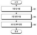
도 5는 본 개시의 다양한 실시 예들에 따른, 방향 추정을 위한 제1 장치의 동작 흐름을 도시한다. 제1 장치는 기지국 110 또는 단말 120을 포함할 수 있다. 제2 장치는 기지국 110 또는 단말 120을 포함할 수 있다.FIG. 5 illustrates an operation flow of a first device for direction estimation according to various embodiments of the present disclosure. The first device may include a
도 5를 참고하면, 501 단계에서, 제1 장치는 빔 셋을 결정할 수 있다. 제1 장치는 빔 훈련(beam training)을 위한 빔 셋을 결정할 수 있다. 여기서, 빔 훈련이란, 특정 장치(예: 기지국 110)가 순차적으로 빔 방향을 달리하여 신호들을 상대방 장치에게 전송함으로써, 빔 셋의 복수의 빔들 중 상대 장치(예: 다른 장치 120)와 통신하기에 적합한 빔을 식별하기 위한 절차를 의미한다. 다양한 실시 예들에 따른 빔 셋의 빔은 후술되는 보조 빔 페어의 빔 대비 넓은 빔 폭을 가지게 되므로, 와이드 빔 셋(wide beam set)으로 지칭될 수 있다.Referring to FIG. 5, in
빔 셋에 포함된 개수가 클수록, 제2 장치가 위치하는 방향의 정확도는 증가할 수 있다. 빔 훈련에 이용되는 빔들이 많을수록 방향에 대한 해상도가 증가하기 때문이다. 한편, 빔 훈련에 이용되는 빔들의 개수가 클수록, 빔 훈련을 위해 송신되는 신호들의 개수가 많아지므로, 통신 방향의 추정을 위한 오버헤드는 증가한다. 반대로, 빔 셋에 포함된 개수가 작을수록 방향 추정의 정확도는 감소할 수 있다. 빔 훈련에 이용되는 빔들이 적을수록 방향에 대한 해상도가 감소하기 때문이다. 마찬가지로, 빔 훈련에 이용되는 빔들의 개수가 작을수록, 빔 훈련을 위해 송신되는 신호들의 개수가 적어지므로 통신 방향을 찾기 위한 오버헤드는 감소한다. 따라서, 제1 장치는 정확도의 향상과 빔 훈련으로 인한 오버헤드 모두를 고려하여, 적절한 빔 셋을 결정할 것이 요구된다.As the number included in the beam set increases, the accuracy of the direction in which the second device is located can increase. This is because the resolution for the direction increases as the number of beams used for beam training increases. On the other hand, as the number of beams used for beam training increases, the number of signals transmitted for beam training increases, and thus the overhead for estimating the communication direction increases. Conversely, as the number included in the beam set decreases, the accuracy of direction estimation can decrease. This is because the resolution for the direction decreases as the number of beams used for beam training decreases. Similarly, as the number of beams used for beam training decreases, the number of signals transmitted for beam training decreases, and thus the overhead for finding the communication direction decreases. Therefore, the first device is required to determine an appropriate beam set by considering both the improvement in accuracy and the overhead due to beam training.
다양한 실시 예들에 따라, 제1 장치는 지정된 빔 폭으로 형성되는 빔들을 포함하는 빔 셋을 결정할 수 있다. 지정된 빔 폭이란 빔 셋의 각 빔의 빔 폭이 특정 조건을 만족함을 의미한다. 특정 조건은 보조 빔 페어의 빔 간격과 관련될 수 있다. 특정 조건은, 보조 빔 페어를 이용한 각도 추정 시, 보조 빔 페어에 대한 벡터들이 간소화되어 표현될 수 있도록 위상의 주기성을 만족시키기 위한 조건일 수 있다. 제1 장치는 안테나 어레이의 안테나들의 개수에 기반하여 빔 셋을 결정할 수 있다. 일 실시 예에 따라, 빔 폭은 반전력 빔 폭(half power beamwidth, HPBW)일 수 있다. 빔 폭은 복사빔 방향을 포함하는패턴 단면에서, 복사 전력 세기가 최대값의 1/2가 되는 두 방향 사이의 각도로 정의될 수 있다.According to various embodiments, the first device can determine a beam set including beams formed with a designated beam width. The designated beam width means that the beam width of each beam of the beam set satisfies a designated condition. The designated condition may be related to a beam spacing of an auxiliary beam pair. The designated condition may be a condition for satisfying a periodicity of a phase so that vectors for the auxiliary beam pair can be expressed in a simplified manner when estimating an angle using the auxiliary beam pair. The first device can determine the beam set based on the number of antennas of the antenna array. According to one embodiment, the beam width may be a half power beamwidth (HPBW). The beam width may be defined as an angle between two directions in which a radiated power intensity is half of a maximum value in a pattern cross-section including a radiated beam direction.
다양한 실시 예들에 따라, 제1 장치는, 보조 빔 페어들의 빔들 간 빔 간격에 기반하여 빔 폭을 결정할 수 있다. 빔 간격은, 빔들의 중심 방향들이 물리적으로 이루는 각도를 의미한다. 보조 빔 페어가 특정 각도를 이루도록 설정하기 위하여, 제1 장치는 특정 각도에 기반하여 빔 폭을 결정할 수 있다. 이는 기준 빔에 기반하여 추후 보조 빔 페어를 결정하기 위함이다.According to various embodiments, the first device can determine the beam width based on the beam spacing between the beams of the auxiliary beam pairs. The beam spacing means the angle that the center directions of the beams physically make. In order to set the auxiliary beam pair to form a specific angle, the first device can determine the beam width based on the specific angle. This is to determine the auxiliary beam pair later based on the reference beam.
다양한 실시 예들에 따라, 제1 장치는 빔 폭 및 제공하고자 하는 커버리지에 기반하여, 빔 셋을 결정할 수 있다. 커버리지는 빔포밍을 통해 전송하고자 하는 신호의 방향 범위를 포함할 수 있다. 고정된 커버리지 내에서, 빔 폭이 클수록 빔 셋의 빔들의 개수는 적을 수 있다. 반대로, 고정된 커버리지 내에서, 빔 폭이 작을수록 빔 셋의 빔들의 개수는 증가할 수 있다.According to various embodiments, the first device can determine a beam set based on a beam width and a coverage to be provided. The coverage can include a directional range of a signal to be transmitted via beamforming. Within a fixed coverage, a larger beam width can lead to a smaller number of beams in the beam set. Conversely, within a fixed coverage, a smaller beam width can lead to an increased number of beams in the beam set.
503 단계에서, 제1 장치는 빔 셋을 이용하여 신호를 송신할 수 있다. 빔 셋은 복수의 빔들을 포함할 수 있다. 복수의 빔들 각각은 서로 다른 방향을 가리킬 수 있다. 제1 장치는 복수의 빔들 각각을 이용하여 신호를 송신할 수 있다. 제1 장치는 빔 방향을 달리하여 순차적으로 빔 셋의 빔을 이용하여 신호를 반복적으로 송신할 수 있다. 예를 들어, 제1 장치는, 빔 스위핑(beam sweeping)을 수행할 수 있다.At
신호는 빔포밍된 신호일 수 있다. 다양한 실시 예들에 따라, 빔포밍된 신호는 동기 신호를 포함할 수 있다. 예를 들어, 동기 신호는 PSS(primary synchronization signal), SSS(secondary synchronization signal), ESS(extended synchronization signal) 중 적어도 하나일 수 있다. 또한, 예를 들어, 동기 신호는 SS 블록(block)일 수 있다. 다양한 실시 예들에 따라, 빔포밍된 신호는 기준 신호를 포함할 수도 있다. 예를 들어, 기준 신호는 BRS, BRRS(beam refinement reference signal), CRS(cell-specific reference signal), CSI-RS(channel state information-reference signal), DM-RS(demodulation-reference signal) 중 적어도 하나일 수 있다.The signal may be a beamformed signal. According to various embodiments, the beamformed signal may include a synchronization signal. For example, the synchronization signal may be at least one of a primary synchronization signal (PSS), a secondary synchronization signal (SSS), and an extended synchronization signal (ESS). Also, for example, the synchronization signal may be an SS block. According to various embodiments, the beamformed signal may also include a reference signal. For example, the reference signal may be at least one of a BRS, a beam refinement reference signal (BRRS), a cell-specific reference signal (CRS), a channel state information-reference signal (CSI-RS), and a demodulation-reference signal (DM-RS).
505 단계에서, 제1 장치는 적어도 하나의 빔을 가리키기 위한 신호를 수신할 수 있다. 제1 장치는 제2 장치로부터 상기 빔 셋의 빔들 중 적어도 하나의 빔을 가리키기 위한 신호를 수신할 수 있다. 제2 장치는 503 단계의 신호를 수신할 수 있다. 제2 장치는 503 단계의 빔을 달리하여 전송된 신호들을 수신하고, 수신된 신호들을 측정할 수 있다.At
본 개시에서, 신호들의 측정을 위한 메트릭은 예를 들어, BRSRP(beam reference signal received power), RSRP, RSRQ(reference signal received quality), RSSI(received signal strength indicator), SINR(signal to interference and noise ratio), CINR(carrier to interference and noise ratio), SNR, EVM(error vector magnitude), BER(bit error rate), BLER(block error rate) 중 적어도 하나일 수 있다. 상술한 예 외에도, 이와 동등한 기술적 의미를 가지는 다른 용어들 혹은 채널 품질을 나타내는 다른 지표(metric)들이 사용될 수 있음은 물론이다. 본 개시에서 채널 품질이 높음은, 신호 크기 관련의 채널 품질 값이 크거나 또는 오류율 관련 채널 품질 값이 작은 경우를 의미한다. 채널 품질이 높을수록, 원활한 무선 통신 환경이 보장됨을 의미할 수 있다. 또한, 최적의 빔이란 빔들 중 채널 품질이 가장 높은 빔을 의미할 수 있다. 이하, 빔포밍 신호의 크기를 결정하는 채널 품질은 RSRP를 예로 서술한다.In the present disclosure, a metric for measuring signals may be, for example, at least one of BRSRP (beam reference signal received power), RSRP, RSRQ (reference signal received quality), RSSI (received signal strength indicator), SINR (signal to interference and noise ratio), CINR (carrier to interference and noise ratio), SNR, EVM (error vector magnitude), BER (bit error rate), and BLER (block error rate). In addition to the examples described above, it goes without saying that other terms having equivalent technical meanings or other metrics indicating channel quality may be used. In the present disclosure, high channel quality means a case where a channel quality value related to a signal size is large or a channel quality value related to an error rate is small. A higher channel quality may mean that a smooth wireless communication environment is guaranteed. In addition, an optimal beam may mean a beam with the highest channel quality among beams. Hereinafter, the channel quality that determines the size of a beamforming signal is described as an example of RSRP.
제2 장치는 측정 결과에 기반하여, 복수의 빔들 중 적어도 하나의 빔을 가리키기 위한 신호를 제1 장치에게 전송할 수 있다. 제2 장치는, 가장 양호한 채널 상태를 제공하는 빔, 즉 신호들 중 채널 품질이 가장 높게 측정된 신호에 대응하는 빔(또는 자원)을 가리키는 신호를 제1 장치에게 전송할 수 있다. 예를 들어, 제2 장치는 복수의 기준 신호들 중 RSRP가 가장 높은 기준 신호를 제1 장치에게 피드백할 수 있다.The second device may transmit a signal to the first device for indicating at least one beam among the plurality of beams based on the measurement result. The second device may transmit a signal to the first device for indicating a beam providing the best channel condition, i.e., a beam (or resource) corresponding to a signal whose channel quality is measured to be the highest among the signals. For example, the second device may feed back a reference signal having the highest RSRP among the plurality of reference signals to the first device.
제1 장치는, 제2 장치로부터 적어도 하나의 빔을 가리키기 위한 신호를 수신함으로써, 빔 셋의 복수의 빔들 중 어떤 빔이 제2 장치와 통신하기에 상대적으로 적절한 지 결정할 수 있다. 일부 실시 예들에서, 제1 장치는 상기 적어도 하나의 빔을 가리키는 정보를 포함하는 피드백 정보를 제1 장치에게 전송할 수 있다. 피드백 정보는 명시적으로(explicitly) 적어도 하나의 빔을 가리킬 수 있다. 예를 들어, 피드백 정보는 CSI-RS의 자원을 포함할 수 있다. 다른 일부 실시 예들에서, 제1 장치는 상기 적어도 하나의 빔을 가리키기 위한 자원 영역 상에서 특정 신호를 수신할 수 있다. 특정 신호는 암묵적으로(implicitly) 적어도 하나의 빔을 가리킬 수 있다. 예를 들어, 특정 신호는 Random access preamble을 포함할 수 있다.The first device can determine which of a plurality of beams of the beam set is relatively suitable for communicating with the second device by receiving a signal from the second device for indicating at least one beam. In some embodiments, the first device can transmit feedback information including information indicating the at least one beam to the first device. The feedback information can explicitly indicate the at least one beam. For example, the feedback information can include a resource of a CSI-RS. In some other embodiments, the first device can receive a specific signal on a resource region for indicating the at least one beam. The specific signal can implicitly indicate the at least one beam. For example, the specific signal can include a random access preamble.
507 단계에서, 제1 장치는 보조 빔 페어를 결정할 수 있다. 본 개시의 다양한 실시 예들에서, 보조 빔 페어란 본 장치(예: 제1 장치)와 상대 장치(예: 제2 장치) 간 통신을 위해 요구되는, 신호의 물리적인 경로의 방향(이하, 통신 방향)를 정확히 추정하기 위해 이용되는 빔 쌍을 의미할 수 있다. 보조 빔 페어의 두 빔들 각각에 대한 채널 품질(예: 수신 전력, RSRP)에 기반하여, 제1 장치는 두 빔들의 방향들 사이에 위치하는 통신 방향을 보다 정확히 추정할 수 있다.At
제1 장치는 빔 셋의 빔들 중 기준 빔을 식별할 수 있다. 제1 장치는 기준 빔을 결정하기 위해, 505 단계의 제2 장치로부터 수신한 적어도 하나의 빔에 대한 정보를 획득할 수 있다. 제1 장치는 적어도 하나의 빔 중에서 기준 빔을 식별할 수 있다. 다양한 실시 예들에 따라, 적어도 하나의 빔은 빔 셋의 복수의 빔들 중에서 채널 품질에 따라 식별될 수 있다. 제1 장치는 빔 셋의 복수의 빔들 중 가장 높은 채널 품질을 갖는 빔을 결정할 수 있다. 보다 높은 채널 품질을 제공하는 빔의 방향이 통신 방향과 보다 유사하기 때문이다. 제1 장치는 가장 높은 채널 품질에 대응하는 빔을 기준 빔으로 결정할 수 있다.The first device can identify a reference beam among the beams of the beam set. The first device can obtain information about at least one beam received from the second device in
제1 장치는 기준 빔의 방향을 기준 방향으로 결정할 수 있다. 여기서, 기준 빔의 방향이란, 기준 빔의 중심 방향을 의미할 수 있다. 예를 들어, 기준 빔의 방향은, 기준 빔을 형성하는 안테나의 복사 패턴 중 메인 로브(main lobe)에 대응하는 방향, 즉 조준 방향으로 결정될 수 있다. 제1 장치는 기준 방향으로부터 대칭되는 두 빔들을 보조 빔 페어로 결정할 수 있다.The first device can determine the direction of the reference beam as the reference direction. Here, the direction of the reference beam can mean the center direction of the reference beam. For example, the direction of the reference beam can be determined as the direction corresponding to the main lobe among the radiation patterns of the antenna forming the reference beam, that is, the aiming direction. The first device can determine two beams that are symmetrical from the reference direction as the auxiliary beam pair.
다양한 실시 예들에 따를 때, 제1 장치는 기준 방향을 중심으로 대칭인(symmetric) 두 방향들에 대응하는 두 빔들을 빔 페어로 결정할 수 있다. 다시 말해, 보조 빔 페어의 두 빔들은 503 단계 내지 505 단계를 통해 획득된 기준 빔의 중심 방향을 기준으로 대칭일 수 있다. 제1 장치는 빔 셋의 빔들을 이용하는 것이 아니라, 기준 방향을 중심으로 대칭을 형성하도록 빔을 재형성할 수 있다. 다시 말해, 다양한 실시 예들에 따른 보조 빔 페어는, 빔 셋의 빔들과 다를 수 있다. 보조 빔 페어의 각 빔은 빔 셋의 각 빔의 조준 방향과 다른 방향을 갖는다.According to various embodiments, the first device may determine two beams corresponding to two directions that are symmetric about a reference direction as a beam pair. In other words, the two beams of the auxiliary beam pair may be symmetric about the center direction of the reference beam obtained through
다양한 실시 예들에 따를 때, 제1 장치는 501 단계에서 결정된 빔 셋 의 빔들 중에서 보조 빔 페어의 빔들을 식별하는 것이 아니라, 결정된 기준 방향에 기반하여 보조 빔 페어를 결정하기 위한 빔 셋을 새로이 결정할 수 있다. 이후, 제1 장치는 새로이 결정된 빔 셋의 빔들로부터 보조 빔 페어를 결정할 수 있다. 501 단계의 빔 셋은 1차(primary) 빔 셋으로 지칭될 수 있다. 적어도 하나의 보조 빔 페어의 빔들은 2차(secondary) 빔 셋으로 지칭될 수 있다. 기준 신호를 전송하고 이에 대한 수신 전력을 피드백 받는 과정 또한 빔 훈련의 일 예로서 볼 수 있으므로, 적어도 하나의 보조 빔 페어의 빔들은, 501 단계의 빔 셋과 구별하기 위하여, 2차 빔 셋으로 지칭될 수 있다.According to various embodiments, the first device may determine a new beam set for determining the auxiliary beam pair based on the determined reference direction, rather than identifying the beams of the auxiliary beam pair among the beams of the beam set determined in
다양한 실시 예들에 따를 때, 제1 장치는 기준 방향과 지정된 각도를 이루는 방향들 중 상호 대칭인 두 방향들을 제공하는 빔들을 보조 빔 페어로 결정할 수 있다. 보조 빔 페어는, 501 단계에서 결정된 빔 셋의 빔 폭에 기반하여 결정될 수 있다. 빔 셋 결정 시, 보조 빔 페어의 빔 간격을 고려하여 빔 폭을 결정하였으므로, 제1 장치는, 기준 빔의 빔 폭에 기반하여 보조 빔 페어를 결정할 수 있다. 일 실시 예에 따라, 제1 장치는 기준 빔의 빔 폭이 보조 빔 페어의 빔 간격과 동일하도록, 보조 빔 페어를 결정할 수 있다. 다른 일 실시 예에 따라, 제1 장치는 기준 빔의 빔 폭이 보조 빔 페어의 빔 간격의 배수가 되도록, 보조 빔 페어를 결정할 수 있다. 또 다른 일 실시 예에 따라, 제1 장치는 보조 빔 페어의 빔 간격이 기준 빔의 빔 폭의 배수가 되도록, 보조 빔 페어를 결정할 수 있다. 즉, 단순히 기준 방향으로부터 대칭인 빔들뿐만 아니라, 기준 방향에 관하여 대칭인 빔들 각각의 방향이 기준 방향과 이루는 각도에 기반하여, 제1 장치는 보조 빔 페어를 결정할 수 있다. 상기 각도의 두 배는 보조 빔 페어의 빔들 간 빔 간격일 수 있다. 다시 말해, 제1 장치는 지정된 빔 간격에 기반하여 보조 빔 페어를 결정할 수 있다. 일부 실시 예들에서, 제1 장치는, 보조 빔 페어의 각 빔 형성 시 이용되는 안테나 어레이의 안테나 개수에 기반하여, 빔 간격을 지정할 수 있다.According to various embodiments, the first device may determine beams providing two mutually symmetrical directions among directions forming a specified angle with a reference direction as auxiliary beam pairs. The auxiliary beam pair may be determined based on the beam width of the beam set determined in
509 단계에서, 제1 장치는 보조 빔 페어를 이용하여 기준 신호를 송신할 수 있다. 보조 빔 페어는, 제1 장치의 빔 쌍을 포함할 수 있다. 빔 쌍은 제1 장치의 2개의 빔들을 포함할 수 있다. 이하, 설명의 편의를 위하여 하나의 보조 빔 페어를 이용하여, 본 개시의 2-단계 방향 추정 기법을 서술하나, 본 개시는 이에 한정되지 않는다. 2-단계 방향 추정 기법을 수행하기 위하여, 복수의 보조 빔 페어들이 이용될 수 있다.At
보조 빔 페어는 제1 장치의 제1 빔 및 제1 장치의 제2 빔을 포함할 수 있다. 통신 각도는 제1 빔과 제2 빔 사이에 위치할 수 있다. 제1 장치는 정확한 통신 각도를 추정하기 위하여, 제1 빔과 제2 빔을 이용하여 각각 기준 신호를 송신할 수 있다. 제1 장치는 제1 빔을 이용하여 제1 기준 신호를 송신할 수 있다. 제2 장치는 제2 빔을 이용하여 제2 기준 신호를 송신할 수 있다. 여기서, 사용되는 기준 신호는 BRS, BRRS, CRS, CSI-RS, DM-RS 중 적어도 하나일 수 있다.The auxiliary beam pair may include a first beam of the first device and a second beam of the first device. The communication angle may be located between the first beam and the second beam. The first device may transmit reference signals using the first beam and the second beam, respectively, to estimate an accurate communication angle. The first device may transmit the first reference signal using the first beam. The second device may transmit the second reference signal using the second beam. Here, the reference signal used may be at least one of a BRS, a BRRS, a CRS, a CSI-RS, and a DM-RS.
다양한 실시 예들에 따를 때, 보조 빔 페어의 각 빔의 빔 폭은, 501 단계에서 결정된 빔 셋의 각 빔의 빔 폭보다 좁을 수 있다. 즉, 제1 빔 또는 제2 빔의 빔 폭은, 빔 셋의 복수의 빔들 각각의 빔 폭보다 좁을 수 있다. 빔 셋을 통한 빔 훈련 이후, 보조 빔 페어를 이용함으로써, 보다 정밀한 각도 추정을 수행하기 위함이다.According to various embodiments, the beam width of each beam of the auxiliary beam pair may be narrower than the beam width of each beam of the beam set determined in
511 단계에서, 제1 장치는 피드백 정보를 수신할 수 있다. 제1 장치는 보조 빔 페어에 대한 피드백 정보를 수신할 수 있다. 제1 장치는 제1 빔에 대한 피드백 정보를 수신할 수 있다. 피드백 정보는 제1 빔에 대한 채널 품질을 포함할 수 있다. 예를 들어, 피드백 정보는 제1 빔을 이용하여 송신된 제1 기준 신호의 수신 전력 값을 포함할 수 있다. 일 예로, 피드백 정보는 제1 기준 신호의 RSRP를 포함할 수 있다. 제1 장치는 제2 빔에 대한 피드백 정보를 수신할 수 있다. 피드백 정보는 제2 빔에 대한 채널 품질을 포함할 수 있다. 예를 들어, 피드백 정보는 제2 빔을 이용하여 송신된 제2 기준 신호의 수신 전력 값을 포함할 수 있다. 일 예로, 피드백 정보는 제2 기준 신호의 RSRP를 포함할 수 있다.At
제1 장치는 제1 빔에 대한 채널 품질과 제2 빔에 대한 채널 품질을 다양한 방법으로 획득할 수 있다. 일부 실시 예들에서, 제1 빔에 대한 피드백 정보와 제2 빔에 대한 피드백 정보는 하나의 메시지로서 한 회의 시그널링을 통해 피드백될 수 있다. 다른 일부 실시 예들에서, 제1 빔에 대한 피드백 정보와 제2 빔에 대한 피드백 정보는 각각 독립적인 신호로 전송될 수 있다.The first device can obtain the channel quality for the first beam and the channel quality for the second beam in various ways. In some embodiments, the feedback information for the first beam and the feedback information for the second beam can be fed back as one message through one signaling. In some other embodiments, the feedback information for the first beam and the feedback information for the second beam can be transmitted as independent signals, respectively.
513 단계에서, 제1 장치는 방향을 결정할 수 있다. 다양한 실시 예들에 따라, 제1 장치는, 기준 빔의 방향 정보에 기반하여, 통신 방향을 결정할 수 있다. 501 단계의 빔 셋의 빔들 중에서 기준 빔이 가장 높은 채널 품질을 제공하므로, 빔 셋의 빔들 중에서 기준 빔의 방향이 통신 방향과 가장 오차가 적을 수 있기 때문이다. 제1 장치는, 기준 방향에 대한 방향 정보를 획득할 수 있다. 여기서, 기준 방향에 대한 방향 정보는, 기준 빔에 의해 형성되는 물리적인 신호 경로의 절대적인 방향 벡터를 포함할 수 있다.In
제1 장치는 피드백 정보에 기반하여 방향을 결정할 수 있다. 여기서 방향이란 제1 장치가 제2 장치와 통신을 수행하기 위한 최적의 각도에 대응하는 방향일 수 있다. 최적의 각도는 최적의 통신 품질을 제공하는 통신 방향을 의미할 수 있다. 통신 방향은 제1 장치와 제2 장치 간 최적의 통신을 위한 신호의 물리적인 경로와 관련될 수 있다. 예를 들어, 상기 통신 방향은, 제1 장치가 제2 장치와 원활한 통신을 위해 요구되는 제1 장치의 신호의 AoD(또는 AoA)를 의미할 수 있다. 본 개시에서 통신 방향의 결정은 통신 방향의 추정, 각도의 추정, 통신 각도의 결정 등으로 표현될 수 있다. 결정되는 통신 방향은, 해당 방향으로 빔을 형성하기 위한 안테나 어레이의 벡터에 기반하여 표현될 수 있다.The first device can determine a direction based on feedback information. Here, the direction may be a direction corresponding to an optimal angle for the first device to communicate with the second device. The optimal angle may mean a communication direction that provides optimal communication quality. The communication direction may be related to a physical path of a signal for optimal communication between the first device and the second device. For example, the communication direction may mean an AoD (or AoA) of a signal of the first device required for smooth communication between the first device and the second device. In the present disclosure, the determination of the communication direction may be expressed as estimation of the communication direction, estimation of the angle, determination of the communication angle, etc. The determined communication direction may be expressed based on a vector of an antenna array for forming a beam in the corresponding direction.
다양한 실시 예들에 따라, 제1 장치는, 제1 기준 신호에 대한 채널 품질(예: 제1 RSRP) 및 제2 기준 신호에 대한 채널 품질(예: 제2 RSRP)에 기반하여, 통신 방향을 결정할 수 있다. 제1 기준 신호가 전송된 방향과 제2 기준 신호가 전송된 방향 사이에 제2 장치를 위한 통신 방향이 위치할 수 있기 때문이다. 제1 장치는 방향 정보 및 보조 빔 페어의 채널 품질 정보(예: 제1 RSRP, 제2 RSRP)에 기반하여, 통신 방향을 결정할 수 있다.According to various embodiments, the first device can determine the communication direction based on the channel quality for the first reference signal (e.g., the first RSRP) and the channel quality for the second reference signal (e.g., the second RSRP). This is because the communication direction for the second device can be located between the direction in which the first reference signal is transmitted and the direction in which the second reference signal is transmitted. The first device can determine the communication direction based on the direction information and the channel quality information of the auxiliary beam pair (e.g., the first RSRP, the second RSRP).
도 5에는 도시되지 않았으나, 제1 장치는 획득한 통신 방향에 기반하여 제2 장치와 빔포밍 통신을 수행할 수 있다. 제1 장치는 통신 방향에 대응하는 적어도 하나의 빔을 형성할 수 있다. 제1 장치는 통신 방향에 대응하는 빔을 이용하여 데이터를 제2 장치에게 전송할 수 있다. 제1 장치는, 보다 정확한 통신 방향(통신 각도)를 획득함으로써, 제2 장치와의 빔포밍 통신의 품질을 높일 수 있다. 또한, 제1 장치는 획득한 통신 방향에 기반하여, 빔 훈련을 위한 빔들 중 적어도 하나의 빔을 식별함으로써, 빔 훈련으로 인한 오버헤드를 줄일 수 있다.Although not shown in FIG. 5, the first device can perform beamforming communication with the second device based on the acquired communication direction. The first device can form at least one beam corresponding to the communication direction. The first device can transmit data to the second device using the beam corresponding to the communication direction. The first device can improve the quality of beamforming communication with the second device by acquiring a more accurate communication direction (communication angle). In addition, the first device can reduce overhead due to beam training by identifying at least one beam among beams for beam training based on the acquired communication direction.
도 5는 보조 빔 페어를 이용하여 전송되는 신호의 예로, 기준 신호가 서술되었으나, 본 개시는 이에 한정되지 않는다, 일 실시 예에 따라 기준 신호 대신 동기 신호가 사용되거나 데이터를 포함하는 빔포밍된 신호가 보조 빔 페어를 이용한 방향 추정에 사용될 수도 있다.FIG. 5 is an example of a signal transmitted using an auxiliary beam pair. Although a reference signal is described, the present disclosure is not limited thereto. In one embodiment, a synchronization signal may be used instead of a reference signal, or a beamformed signal including data may be used for direction estimation using an auxiliary beam pair.
도 6은 본 개시의 다양한 실시 예들에 따른, 방향 추정의 예를 도시한다. 도 6의 방향 추정은, 빔 셋 및 보조 빔 페어를 이용하는, 도 5에 도시된 통신 방향의 추정 절차를 예시한다. 제1 장치는 송신 장치로써 AoD를 추정하고, 제2 장치는 수신 장치로써 AoA를 추정하는 상황이 서술된다.FIG. 6 illustrates an example of direction estimation according to various embodiments of the present disclosure. The direction estimation of FIG. 6 illustrates a procedure for estimating a communication direction as illustrated in FIG. 5 using a beam set and an auxiliary beam pair. A situation is described where a first device estimates an AoD as a transmitting device and a second device estimates an AoA as a receiving device.
도 6을 참고하면, 제1 장치와 제2 장치는 채널 601을 통해 통신을 수행할 수 있다. 제1 장치는 채널 601을 통해 제2 장치에게 신호를 송신할 수 있다. 제2 장치는 채널 601을 통해 제1 장치로부터 신호를 수신할 수 있다.Referring to FIG. 6, the first device and the second device can communicate via
제1 장치는 송신 안테나 어레이(antenna array) 610을 포함할 수 있다. 송신 안테나 어레이 610은 빔 셋의 송신 빔들 611, 612, 613, 614, 615, 616을 각각 형성할 수 있다. 빔 셋의 결정은 후술되는 도 7 내지 도 8을 통해 구체적으로 서술된다. 제1 장치는 송신 안테나 어레이 610의 빔들 중 송신 빔 613을 기준 빔으로 결정할 수 있다. 송신 빔 613은 제2 장치와의 빔 훈련 절차에 식별될 수 있다. 일 예로, 송신 빔 613은 송신 빔들 611, 612, 613, 614, 615, 616 중 가장 높은 채널 품질을 제공하는 빔일 수 있다.The first device may include a transmit
제1 장치는 기준 빔인 빔 613으로부터, 보조 빔 페어 621, 623을 결정할 수 있다. 빔 613의 조준 방향은 기준 방향 625로 결정될 수 있다. 제1 장치는 기준 방향 625에 대칭되는 빔 쌍을 보조 빔 페어로 결정할 수 있다. 예를 들어, 제1 장치는 송신 빔 613이 형성하는 각도의 양 끝에 위치한 제1 빔 621, 제2 빔 623을 보조 빔 페어의 빔 쌍으로 결정할 수 있다. 통신 방향은 송신 빔 613의 커버리지, 즉 송신 빔 613의 빔 폭이 제공하는 각도 범위 내 위치하기 때문이다.The first device can determine an
제2 장치는 수신 안테나 어레이 630을 포함할 수 있다. 수신 안테나 어레이 630은 빔 셋의 수신 빔들 631, 632, 633, 634, 635, 636을 각각 형성할 수 있다. 제2 장치는 수신 안테나 어레이 630의 빔들 중 수신 빔 633을 기준 빔으로 결정할 수 있다. 일 예로, 수신 빔 633은 빔 훈련 절차를 통해 결정될 수 있다.The second device may include a receive
안테나 어레이에서 형성되는 빔은, 벡터의 형태로 표현될 수 있다. 즉, 모든 송신 빔과 수신 빔은 어레이 응답 벡터의 형태로 구성될 수 있다. 따라서, 제1 장치에 의해 결정되는 보조 빔 페어의 빔들, 즉 제1 빔 621 및 제2 빔 623은, 하기의 수학식 1과 같이 표현될 수 있다.The beams formed in the antenna array can be expressed in the form of vectors. That is, all transmit beams and receive beams can be configured in the form of array response vectors. Accordingly, the beams of the auxiliary beam pair determined by the first device, that is, the


다양한 실시 예들에 따를 때, 제1 장치는 수학식 2에 따라


제1 장치와 제2 장치 간 무선 통신 경로로서 채널 601은, MIMO 채널로서 단일 경로(single-path)일 수 있다. 실제 통신 신호가 겪는 채널 601은, MIMO 단일 경로로서 하기의 수학식 3으로 표현될 수 있다.
여기서,


여기서


다양한 실시 예에 따라, 송신 방향 650에 대응하는 송신 각도(예: AoD(μ))를 추정 시, 제1 장치는 수신 방향 660에 대응하는 수신 각도(예: AoA(ψ))에 대한 정보를 미리 획득할 수 있다. 일부 실시 예들에서, 제1 장치는 수신 각도에 대한 정보를 제2 장치로부터 획득할 수 있다. 예를 들어, 제2 장치는 수신 각도에 대한 정보를 제1 장치에게 피드백할 수 있다. 다른 일부 실시 예들에서, 수신 각도에 대한 정보는 미리 결정될 수 있다. 예를 들어, 수신 단말이 넓은 빔 폭을 갖는 빔(예: 옴니(omni-directional) 빔)을 통해 신호를 수신함으로써, 수신 각도에 대한 정보는 미리 결정될 수 있다.According to various embodiments, when estimating a transmission angle (e.g., AoD(μ)) corresponding to a
수학식 4의 보조 빔 페어의 빔들(즉, 제1 빔 621, 제2 빔 623)을 이용하여 전송된 신호의 전력은 하기의 수학식 5와 같이 표현될 수 있다.The power of a signal transmitted using the beams of the auxiliary beam pair of Equation 4 (i.e., the


수학식 5의
다양한 실시 예들에 따를 때, 수학식 7은, 빔 간격이 수학식 2를 만족하면, 하기의 수학식 8과 같이 표현될 수 있다.According to various embodiments, mathematical expression 7 can be expressed as
제1 장치는 보조 빔 페어의 빔들 각각의 수신 전력을 이용하여, 비율 지표(ratio metric)를 획득할 수 있다. 여기서 비율 지표는, 기준 방향 625와 실제 추정되는 통신 방향 650 간의 차이를 결정하기 위한 지표일 수 있다. 비율 지표는 하기의 수학식 9와 같이 표현될 수 있다.The first device can obtain a ratio metric by using the received power of each beam of the auxiliary beam pair. Here, the ratio metric can be an metric for determining a difference between the

수학식 9는, 수학식 8을 이용하여, 하기의 수학식 10과 같이 표현될 수 있다.Mathematical expression 9 can be expressed as


도 6을 통해, 보조 빔 페어를 통해 통신 경로의 송신 방향 650, 즉 AoD를 추정하는 방식이 서술되었으나, 본 개시는 이에 한정되지 않는다. 제2 장치는, 유사한 방식으로 보조 빔 페어를 통신 경로의 수신 방향 660, 즉 AoA를 추정할 수 있다. 일 실시 예에 따라, 제2 장치는, 송신 방향 650에 대응하는 각도에 대한 정보(예: AoD(μ)에 대한 정보)를 제1 장치로부터 획득할 수 있다. 제2 장치는 제1 장치의 각 보조 빔 페어의 수신 전력과, 송신 방향 650에 대응하는 송신 각도에 대한 정보에 기반하여, 수신 각도인 AoA를 추정할 수 있다. 다른 일 실시 예에 따라, 제2 장치는, 수신 빔 스위핑을 통해 기준 수신 빔을 식별하고, 기준 수신 빔의 방향에 따라 결정되는 보조 빔 벡터를 이용하여 수신 각도인 AoA를 추정할 수 있다.Although a method of estimating the
도 6에서는, 하나의 빔 페어를 기준으로 보조 빔 페어를 이용한 각도 추정 기법이 서술되었다. 그러나, 전술한 바와 같이, 복수의 보조 빔 페어들을 이용하여 본 개시의 방향 추정이 가능함은 물론이다.In Fig. 6, an angle estimation technique using an auxiliary beam pair based on one beam pair is described. However, as described above, it is of course possible to perform direction estimation of the present disclosure using multiple auxiliary beam pairs.
빔 셋 결정Beam set decision
본 개시의 다양한 실시 예들은, 기준 빔에 기반하여 보조 빔 페어를 결정하고, 보조 빔 페어를 이용하여 각도 추정을 하는 것뿐만 아니라, 기준 빔을 식별하기 위한 빔 셋을 형성하는 절차 또한 본 개시의 실시 예로서 이해될 수 있다. 즉, 본 개시의 2-단계 각도 추정 기법은 보조 빔 페어를 빔 셋의 빔들 중 하나로부터 새로이 형성하는 것뿐만 아니라, 어떠한 빔 셋을 결정할 것인지, 즉 최적의 빔 셋을 결정하기 위한 기준에 대한 실시 예들을 포함할 수 있다. 이하, 도 7 내지 도 8은 빔 셋을 결정하기 위한 실시 예들에 대하여 서술한다.Various embodiments of the present disclosure may be understood as embodiments of the present disclosure, not only for determining an auxiliary beam pair based on a reference beam and performing angle estimation using the auxiliary beam pair, but also for forming a beam set for identifying the reference beam. That is, the two-step angle estimation technique of the present disclosure may include embodiments for not only newly forming an auxiliary beam pair from one of the beams of the beam set, but also for determining which beam set to use, that is, for determining an optimal beam set. Hereinafter, FIGS. 7 and 8 describe embodiments for determining a beam set.
도 7은 본 개시의 다양한 실시 예들에 따른, 빔 셋을 결정하기 위한 제1 장치의 동작 흐름을 도시한다. 도 7은 도 5의 501 단계의 일부로서, 도 7의 동작 흐름은, 제1 장치 또는 제1 장치의 구성 요소로 이해될 수 있다. 제1 장치는 기지국 110 또는 단말 120을 포함할 수 있다.FIG. 7 illustrates an operational flow of a first device for determining a beam set according to various embodiments of the present disclosure. FIG. 7 is a part of
도 7을 참고하면, 701 단계에서, 제1 장치는 커버리지를 결정할 수 있다. 여기서, 커버리지는 제1 장치에서 송신하고자 하는 통신 방향의 물리적인 범위를 포함할 수 있다. 예를 들어, 제1 장치는 180도(즉, π 라디안)에 대응하는 영역을 커버리지로 결정할 수 있다. 다른 예를 들어, 제1 장치는 120도에 대응하는 영역(예: -60도부터 + 60도의 범위)을 커버리지로 결정할 수 있다. 또 다른 예를 들어, 제1 장치는 360도에 대응하는 영역, 즉 전 방향을 커버리지로 결정할 수 있다.Referring to FIG. 7, at
703 단계에서, 제1 장치는 빔 폭을 결정할 수 있다. 제1 장치는 보조 빔 페어의 결정을 용이하게 하기 위한 빔 폭을 결정할 수 있다. 제1 장치는 빔 훈련 시 이용되는 빔 셋의 빔들을 보조 빔 페어로 결정하게 되면, 가장 큰 수신 전력을 제공하는 빔의 방향 외에 다른 빔의 방향을 고려하게 됨으로써, 실제 방향 간 오차가 발생할 수 있다. 따라서, 제1 장치는 최적의 빔(즉, 가장 높은 통신 품질을 제공하는 빔)에서 보조 빔 페어를 용이하게 결정하기 위해, 빔 셋에 대한 빔 폭을 결정할 수 있다.In
다양한 실시 예들에 따를 때, 제1 장치는 지정된 각도에 기반하여 빔 폭을 결정할 수 있다. 지정된 각도는 안테나 어레이의 안테나들의 개수에 기반하여 결정될 수 있다. 또한, 지정된 각도는 비율 지표가 단조 특성을 충족하기 위한 각도일 수 있다. 여기서, 비율 지표는 방향과 전력 간의 관계를 나타내기 위한 지표일 수 있다. 예를 들어, 제1 장치는 수학식 2에 따라 정의되는 각도에 기반하여 빔 폭을 결정할 수 있다. 즉, 제1 장치는 보조 빔 페어의 빔 간격에 기반하여 빔 폭을 결정할 수 있다.According to various embodiments, the first device can determine the beam width based on a specified angle. The specified angle can be determined based on the number of antennas of the antenna array. In addition, the specified angle can be an angle for a ratio index to satisfy a monotonic characteristic. Here, the ratio index can be an index for representing a relationship between a direction and a power. For example, the first device can determine the beam width based on an angle defined according to
다양한 실시 예들에 따를 때, 제1 장치는 보조 빔 페어의 빔 간격의 배수를 빔 폭으로 결정할 수 있다. 예를 들어, 제1 장치는 2mδ_t (m=1,2,3,..) 가 되도록 빔 셋의 빔 폭을 결정할 수 있다. 여기서, 보조 빔 페어의 간격은 ?2δ?_t일 수 있다. δ_t는 상기 수학식 2에 의해 결정될 수 있다. 빔 간격은 제1 장치의 안테나 어레이 내 안테나 개수에 기반하여 결정될 수 있다. 즉, 제1 장치는, 안테나 어레이 내 안테나 개수에 기반하여 빔 폭을 결정할 수 있다.According to various embodiments, the first device can determine the beam width as a multiple of the beam spacing of the auxiliary beam pair. For example, the first device can determine the beam width of the beam set to be 2mδ_t (m=1,2,3,..). Here, the spacing of the auxiliary beam pair can be ?2δ?_t. δ_t can be determined by the
705 단계에서, 제1 장치는 빔 셋을 결정할 수 있다. 제1 장치는 커버리지 및 빔 간격에 기반하여 빔 셋을 결정할 수 있다. 고정된 커버리지 내에서, 빔 간격이 클수록 빔 셋의 빔들의 개수는 감소할 수 있다. 마찬가지로, 빔 간격이 작을수록 빔들의 개수는 증가할 수 있다. 제1 장치는 결정된 커버리지에 대응하는 방향 범위를 커버하는 빔들의 셋, 즉 빔 셋을 결정할 수 있다. 예를 들어, 고정된 커버리지에 대응하는 방향 범위는 180도(즉, π 라디안)의 크기를 갖고(예: -90도부터 +90도), 빔 간격은 30도(즉,
도 7에서는, 빔 간격 이전에 커버리지를 결정하는 것으로 도시되었으나, 커버리지는 빔 간격 이후 결정되거나 미리 결정될 수 있다. 다시 말해, 도 7에 도시된 순서에 의해 본 개시의 실시 예들이 한정되지 않는다.In FIG. 7, coverage is illustrated as being determined before the beam spacing, but coverage may be determined after the beam spacing or may be determined in advance. In other words, the embodiments of the present disclosure are not limited by the order illustrated in FIG. 7.
도 8은 본 개시의 다양한 실시 예들에 따른, 빔 폭의 예를 도시한다. 도 8을 통해, 빔 훈련을 위한 빔 셋 결정 시, 보조 빔 페어를 위한 빔 폭으로 빔 셋이 결정된 경우(800)와 보조 빔 페어를 고려하지 않은 빔 폭으로 빔 셋이 결정된 경우(850)를 구별하여, 보조 빔 페어의 빔 간격과 빔 셋의 빔 폭 간의 관계가 서술된다. 각 경우의 빔 셋을 통해, 기준 빔이 식별된 상황이다.FIG. 8 illustrates examples of beam widths according to various embodiments of the present disclosure. Through FIG. 8, when determining a beam set for beam training, the relationship between the beam spacing of the auxiliary beam pair and the beam width of the beam set is described by distinguishing between a case where the beam set is determined with a beam width for the auxiliary beam pair (800) and a case where the beam set is determined with a beam width that does not consider the auxiliary beam pair (850). Through the beam set in each case, a reference beam is identified.
도 8을 참고하면, 제1 장치는 기준 빔 800에 기반하여 제1 빔 801 및 제2 빔 803을 결정할 수 있다. 제1 장치는 기준 빔 800의 양 끝 방향의 빔들을 보조 빔 페어로 결정할 수 있다. 실제 통신 방향은 보조 빔 페어의 빔들의 방향들 사이에 위치하므로, 제1 장치는 기준 빔 800의 양 끝 방향들에 대응하는 빔들을 보조 빔 페어로 결정할 수 있다. 기준 빔 800의 빔 폭은

제1 장치는 기준 빔 850에 기반하여 제 3 빔 851 및 제4 빔 853을 결정할 수 있다. 제1 장치는 기준 빔 850의 양 끝 방향의 빔들을 보조 빔 페어로 결정할 수 있다. 기준 빔 850의 빔 폭은

제1 빔 801 및 제2 빔 803을 보조 빔 페어로 이용 시, 제1 장치는 제 3 빔 851 및 제4 빔 853을 보조 빔 페어로 이용하는 경우보다 방향 추정에 대한 높은 정확도를 얻을 수 있다. 기준 빔 800의 빔 폭인

보조 빔 페어 결정Determining the auxiliary beam pair
도 9는 본 개시의 다양한 실시 예들에 따른, 보조 빔 페어를 결정하기 위한 제1 장치의 동작 흐름을 도시한다. 도 9는 도 5의 507 단계의 일부로서, 도 9의 동작 흐름은, 제1 장치 또는 제1 장치의 구성 요소로 이해될 수 있다. 제1 장치는 기지국 110 또는 단말 120을 포함할 수 있다.FIG. 9 illustrates an operational flow of a first device for determining an auxiliary beam pair according to various embodiments of the present disclosure. FIG. 9 is a part of
901 단계에서, 제1 장치는 기준 빔을 식별할 수 있다. 제1 장치는 제1 장치의 빔 셋을 이용하여 빔 훈련을 수행할 수 있다. 빔 셋은 복수의 빔들을 포함할 수 있다. 다시 말해, 제1 장치는, 제1 장치의 복수의 빔들을 이용하여 빔 훈련을 수행할 수 있다. 예를 들어, 제1 장치는 복수의 빔들 각각을 이용하여 기준 신호(또는 동기 신호)를 전송하고, 채널 품질의 측정 결과를 획득함으로써, 복수의 빔들 중 가장 높은 채널 품질을 제공하는 빔을 식별할 수 있다. 제1 장치는 식별된 빔을 기준 빔으로 결정할 수 있다. 다양한 실시 예들에 따라, 제1 장치는 빔 훈련을 위한 빔 셋의 빔들 중 가장 높은 채널 품질을 제공하는 기준 빔을 식별할 수 있다.In
903 단계에서, 제1 장치는 기준 방향을 식별할 수 있다. 제1 장치는 기준 빔에 기반하여, 기준 방향을 식별할 수 있다. 제1 장치는 기준 빔의 중심 방향(예: 조준 방향)을, 기준 방향으로 식별할 수 있다. 조준 방향이란, 안테나에서 방사 시 복사 이득이 최대가 되는 방향을 의미한다. 다양한 실시 예들에 따라, 제1 장치는 빔 셋의 빔들 각각의 조준 방향에 대한 정보를 획득할 수 있다. 방향에 대한 정보는, 빔 형성시 안테나 어레이에서 사용되는 어레이 응답 벡터의 표현으로 구성될 수 있다.At
905 단계에서, 제1 장치는 보조 빔 페어를 결정할 수 있다. 제1 장치는 기준 방향에 대칭인 두 빔들을 보조 빔 페어로 결정할 수 있다. 보조 빔 페어가 제1 빔 및 제2 빔을 포함하는 경우, 제1 빔의 방향과 및 제2 빔의 방향은 기준 방향에 선대칭 관계일 수 있다. 보조 빔 페어는 정밀한 방향 추정을 위한 것이므로, 다양한 실시 예들에 따른 보조 빔 페어의 두 빔들 각각의 빔 폭은 빔 셋의 각 빔의 빔 폭보다 좁을 수 있다.In
제1 장치는, 기준 빔의 빔 폭에 대응하는 범위(이하, 각도 범위) 내에 제2 장치와 통신을 위한 통신 방향이 위치함을 결정할 수 있다. 다양한 실시 예들에 따를 때, 제1 장치는, 보조 빔 페어를 이용하여 상기 통신 방향을 식별하기 위하여 각도 범위의 양 끝에 대응하는 빔들로 보조 빔 페어를 결정할 수 있다.The first device can determine that a communication direction for communication with the second device is located within a range (hereinafter, angular range) corresponding to a beam width of a reference beam. According to various embodiments, the first device can determine an auxiliary beam pair with beams corresponding to both ends of the angular range to identify the communication direction using an auxiliary beam pair.
다양한 실시 예들에 따를 때, 기준 빔의 빔 폭이


일부 실시 예들에서, 제1 장치는, 기준 빔의 양 끝에 대응하는 두 빔들 외에 추가적인 빔 쌍을 보조 빔 페어로 결정할 수 있다. 추가적인 보조 빔 페어의 빔 간격은 수학식 2를 만족할 수 있다. 보다 더 좁은 각도 범위에서 보조 빔 페어를 형성함으로써, 제1 장치는 보다 정밀하게 방향을 추정할 수 있다. 제1 장치는 기준 빔의 양 끝에 대응하는 보조 빔 페어(이하, 1차 빔 페어)를 통해 방향을 추정하고, 추가적으로 더 좁은 각도 범위의 보조 빔 페어(이하, 2차 빔 페어)를 결정할 수 있다. 2차 빔 페어는 상기 수학식 2를 만족하는 빔 간격을 갖는 2차 빔 페어일 수 있다. 예를 들어, 1차 빔 페어의 빔 간격은

도 10은 본 개시의 다양한 실시 예들에 따른, 보조 빔 페어의 예를 도시한다. 도 10을 통해, 보조 빔 페어의 간격과 방향 추정의 정확도(또는 복잡도)간의 관계가 서술된다.FIG. 10 illustrates an example of an auxiliary beam pair according to various embodiments of the present disclosure. Through FIG. 10, the relationship between the spacing of the auxiliary beam pair and the accuracy (or complexity) of direction estimation is described.
도 10을 참고하면, 제1 장치는 제1 보조 빔 페어 1001를 형성할 수 있다. 제1보조 빔 페어 1001의 간격은


수신 전력은 수학식 8과 같이 간소화될 수 있다. 수신 전력에 대한 표현이 간소화됨에 따라, 비율 지표의 단조 속성이 충족될 수 있다. 다시 말해, 빔 페어 1001의 간격이


제1장치는 제2 보조 빔 페어 1003을 형성할 수 있다. 제2보조 빔 페어 1003의 간격은


제1 장치는 제3 보조 빔 페어 1005를 형성할 수 있다. 제3보조 빔 페어 1005의 간격은


도 5 내지 도 10을 통해, 본 개시의 2-단계 방향 추정 기법이 서술되었다. 요컨대, 본 개시에 의할 때, 빔 셋의 빔들을 이용하여 최적의 빔을 통해 개략적인 통신 방향의 각도 범위를 찾고, 최적의 빔에 기반하여 보조 빔 페어를 생성함으로써, 제1 장치는 높은 해상도로 각도를 추정할 수 있다. 빔 셋의 빔들을 이용하여 빔 훈련을 수행한 뒤 추가적으로 보조 빔 페어의 빔들을 이용하여 빔 훈련을 수행함으로써, 적은 오버헤드로 해상도를 높일 수 있다. 상술한 목적 및 효과들을 달성하기 위해, 본 개시는 방향 추정의 정확도를 향상시키기 위한 보조 빔 페어의 빔 간격의 조건을 미리 정의하고, 정의된 조건에 따른 빔 간격을 고려하여 빔 셋의 빔 폭을 결정함으로써, 방향 추정의 해상도를 높일 뿐만 아니라, 적은 개수의 빔들을 통해 적은 추정 오차를 달성할 수 있다.Through FIGS. 5 to 10, the two-step direction estimation technique of the present disclosure is described. In short, according to the present disclosure, by finding an angular range of a rough communication direction through an optimal beam using beams of a beam set, and generating an auxiliary beam pair based on the optimal beam, a first device can estimate an angle with high resolution. By performing beam training using the beams of the beam set and then additionally performing beam training using the beams of the auxiliary beam pair, the resolution can be increased with little overhead. In order to achieve the above-described purposes and effects, the present disclosure defines in advance the conditions of the beam spacing of the auxiliary beam pair for improving the accuracy of direction estimation, and determines the beam width of the beam set by considering the beam spacing according to the defined conditions, thereby not only increasing the resolution of direction estimation but also achieving a small estimation error through a small number of beams.
다양한 실시 예들에 따를 때, 제1 장치는 통신 방향을 추정한 뒤, 추정된 통신 방향에 대응하는 빔을 형성할 수 있다. 제1 장치는 형성된 빔을 통해, 제2 장치와 통신을 수행할 수 있다. 보다 정확한 방향의 빔을 형성함으로써, 제1 장치는 제2 장치에게 보다 높은 통신 품질을 제공할 수 있다. 빔 방향이 실제 통신 방향과 일치함에 따라, 정해진 전력 범위 내에서 경로 손실이 최소화되기 때문이다.According to various embodiments, the first device can estimate a communication direction and then form a beam corresponding to the estimated communication direction. The first device can perform communication with the second device through the formed beam. By forming a beam with a more accurate direction, the first device can provide higher communication quality to the second device. This is because the path loss is minimized within a given power range as the beam direction matches the actual communication direction.
본 개시의 다양한 실시 예들은, 기지국-단말 간 통신뿐만 아니라 단말 간 통신(예: V2X 통신)에도 적용 가능하다. 이하, 도 11 내지 도 12c를 통해, 차량 간 통신(vehicle to vehicle, V2V)을 예로 본 개시의 2-단계 각도 추정 기법이 서술된다.Various embodiments of the present disclosure are applicable not only to base station-terminal communication but also to terminal-to-terminal communication (e.g., V2X communication). Hereinafter, a two-step angle estimation technique of the present disclosure is described using vehicle to vehicle (V2V) communication as an example through FIGS. 11 to 12c.
도 11은 본 개시의 다양한 실시 예들에 따른 차량 간 통신에서 방향 추정의 예를 도시한다.FIG. 11 illustrates an example of direction estimation in vehicle-to-vehicle communication according to various embodiments of the present disclosure.
도 11을 참고하면, 제1 차량 1110은 제2 차량 1120과 빔포밍 통신을 수행할 수 있다. 도로 위에서 차량(예: 제1 차량 1110, 제2 차량 1120)이 주행 중인 경우, 각 차량은 실시간으로 움직인다. 차량 간 빔포밍 통신을 지속하기 위해서는, 각 차량은 차량의 주행과 관련된 정보(이하, 사이드 정보(side information))에 기반하여 적절한 빔을 찾을 것이 요구될 수 있다. 따라서, 각 차량은 사이드 정보를 획득할 것이 요구된다. 제2 차량 1120이 제1 차량 1110에게 신호를 송신하는 상황이 서술된다. 제2 차량 1120의 동작을 중심으로 본 개시의 실시 예들이 서술되나, 대응하는 구성들은 제1 차량 1110에도 동일하게 적용될 수 있다.Referring to FIG. 11, a
제2 차량 1120은, 사이드 정보를 획득할 수 있다. 사이드 정보는, 차량의 속도(velocity), 핸들(steering wheel) 정보, 깜박이 정보(blinker information), 관성 센서 정보 등 적어도 하나를 포함할 수 있다. 일부 실시 예들에서, 제2 차량 1120은, 제1 차량 1110의 사이드 정보를 획득할 수 있다. 제2 차량은 제1 차량 1110으로부터 사이드 정보를 수신할 수 있다. 다른 일부 실시 예들에서, 제2 차량 1120은, 제2 차량 1120의 사이드 정보를 획득할 수 있다. 제2 차량 1120 은 제2 차량 1120의 내부의 센서 등을 통해 사이드 정보를 획득할 수 있다.The
제2 차량 1120은, 사이드 정보에 기반하여, 제2 차량 1120의 통신 방향의 범위를 결정할 수 있다. 예를 들어, 제2 차량 1120은, 제1 차량 1110에게 신호를 송신할 때, 제2 차량 1120의 AoD의 범위를 결정할 수 있다, 마찬가지로, 제1 차량 1110은, 사이드 정보에 기반하여 제1 차량 1110의 통신 방향의 범위를 결정할 수 있다. 예를 들어, 제1 차량 1110은, 제2 차량 1120으로부터 신호를 수신할 때, 제1 차량 1110은 제1 차량 1110의 AoA의 범위를 결정할 수 있다.The
제2 차량 1120은 통신 방향의 범위를 결정함으로써, 커버리지를 결정할 수 있다. 여기서, 커버리지는 도7의 701 단계의 커버리지에 대응할 수 있다. 제2 차량 1120은, 상기 커버리지 내에 위치하는 방향에 대응하는 빔들 중에서, 지정된 빔 폭(예:
제2 차량 1120은, 사이드 정보를 이용하여 통신 방향(송신 방향)의 범위를 미리 결정함으로써, 빔 셋의 후보 빔들을 줄일 수 있다. 사이드 정보를 통해 개략적인 차량 간 위치를 파악함으로써 커버리지가 감소할 수 있다. 커버리지의 감소를 통해, 빔 셋의 빔들의 개수가 줄어들 뿐만 아니라 추후 빔 훈련 시, 각 빔에 대한 오버헤드가 감소할 수 있다. 다시 말해, 제2 차량 1120은 사이드 정보를 통해 보다 효율적으로 빔 셋을 결정할 수 있다. 동일하게, 제1 차량 1110 또한 사이드 정보를 이용하여 통신 방향(수신 방향)의 범위를 미리 결정함으로써, 빔 셋의 후보 빔들을 줄일 수 있다.The
제2 차량 1120은, 감소된 커버리지에 따른 빔 셋을 이용하여 빔 훈련을 수행할 수 있다. 제2 차량 1120은 빔 1130을 기준 빔으로 식별할 수 있다. 제2 차량 1120은 빔 1130의 방향을 기준으로 대칭인 빔 1131 및 빔 1132를 보조 빔 페어로 결정할 수 있다. 제2 차량 1120은, 보조 빔 페어를 통해, 제1 차량 1110에 대한 통신 방향(예: AoD)을 추정할 수 있다. 빔 1130의 빔 폭은, 빔 1131의 빔 폭과 빔 1132의 빔 폭보다 넓을 수 있다. 마찬가지로, 제1 차량 1110은, 감소된 커버리지에 따른 빔 셋을 이용하여 빔 훈련을 수행할 수 있다. 제1 차량 1110은 빔 1140의 방향을 기준으로 대칭인 빔 1141 및 빔 1142를 보조 빔 페어로 결정할 수 있다. 제1 차량 1110은, 보조 빔 페어를 통해, 제2 차량 1120에 대한 통신 방향(예: AoA)을 추정할 수 있다.The
도 12a는 본 개시의 다양한 실시 예들에 따른 차량 간 통신에서 방향 추적(direction tracking)의 예를 도시한다. 정해진 기준 빔의 빔 폭 내에서 통신 방향을 결정하는 동작은, 방향 추적(direction tracking)으로 지칭될 수 있다. 도 12a를 통해, 방향 추적을 위한 차량의 시간 영역 행동(time domain behavior)이 서술된다. 여기서, 방향 추적은 도 5 내지 도 10을 통해 서술된, 다양한 실시 예들에 따른 2-단계 각도 추정 기법에 따른 방향 추정을 포함한다. 차량은 기준 빔에 대한 보조 빔 페어의 빔들을 이용하여, 기준 빔의 커버리지 내에서 통신 방향을 결정할 수 있다.FIG. 12A illustrates an example of direction tracking in vehicle-to-vehicle communication according to various embodiments of the present disclosure. The operation of determining a communication direction within the beam width of a given reference beam may be referred to as direction tracking. Through FIG. 12A, a time domain behavior of a vehicle for direction tracking is described. Here, the direction tracking includes direction estimation according to a two-step angle estimation technique according to various embodiments described through FIGS. 5 to 10. The vehicle can determine a communication direction within the coverage of the reference beam by using beams of an auxiliary beam pair for the reference beam.
도12a를 참고하면, 제2 차량 1120은 주기적 방향 추정 1210을 수행할 수 있다. 제2 차량 1120은 제1 차량 1110과 주기적으로 방향 추정을 수행할 수 있다.Referring to FIG. 12a, the
주기적 시간 흐름 1215를 참고하면, 제2 차량 1120은 구간 1221동안 채널 추정(channel estimation)을 수행할 수 있다. 채널 추정을 통해, 제2 차량 1120은 기준 빔을 식별하고, 기준 방향을 결정할 수 있다. 제2 차량 1120은 구간 1222 동안 데이터 채널(예: DDC(dedicated data channel))을 통해, 제1 차량 1110에게 데이터를 전송할 수 있다. 구간 1222는 데이터 구간으로 지칭될 수 있다. 제2 차량 1120은 구간 1223 동안 전환을 수행할 수 있다. 전환은 통신 채널을 데이터 채널에서 추적 채널(예: DTC(dedicated tracking channel))을 의미한다. 여기서 구간 1220은 전환 구간(transition period, TP)로 지칭될 수 있다. 제2 차량 1120은 구간 1224 동안, 추적 채널을 통해, 제1 차량 1110과 통신을 위한 방향, 즉 통신 방향을 결정할 수 있다. 제2 차량 1120은 기준 방향의 커버리지 내에서 방향 추적을 통해, 통신 방향을 결정할 수 있다. 본 개시의 보조 빔 페어의 결정을 통해, 제2 차량 1120은 제1 차량 1110에 대한 통신 방향을 결정할 수 있다. 구간 1224는 추적 구간으로 지칭될 수 있다.Referring to the
제2 차량 1120은 이후, 전환 구간 동안 통신 채널을 추적 채널에서 데이터 채널로 변경할 수 있다. 제2 차량 1120은 구간 1225에서 다시 데이터 채널을 통해 제1 차량 1110에게 데이터를 전송할 수 있다. 제2 차량 1120은, 전환 구간을 통해 통신 채널을 추적 채널로 변경한 뒤 제1 차량 1110과의 통신 방향을 결정하고, 다시 전환 구간을 통해 통신 채널을 데이터 채널로 재변경한다. 제2 차량 1120은 구간 1226에서 다시 데이터 채널을 통해 제1 차량 1110에게 데이터를 전송할 수 있다. 동일한 구간들(전환 구간?추적 구간?전환 구간)을 거쳐, 제2 차량 1120은 구간 1227에서 다시 데이터 채널을 통해 제1 차량 1110에게 데이터를 전송할 수 있다. 주기적으로, 전환 구간, 추적 구간, 전환 구간, 데이터 구간을 반복함으로써, 제2 차량 1120은 제1 차량 1110에 대한 방향을 주기적으로 추적 수 있다. 또한, 제2 차량 1120은 제1 차량 1110에게 데이터를 주기적으로 송신할 수 있다. 제2 차량 1120은 다음 채널 추정의 구간이 도래하면 다시 기준 빔을 식별하고, 다시 주기적으로 방향 추적을 수행할 수 있다.The
제2 차량 1120은, 비주기적 방향 추정 1260을 수행할 수 있다. 비주기적 방향 추정 1260을 수행하기 위한, 트리거링 조건이 다양하게 정의될 수 있다.The
일부 실시 예들에서, 제2 차량 1120은, 제2 차량 1120의 이동 범위가 임계 범위를 초과하는 경우, 비주기적 방향 추정 1260을 트리거(trigger)할 수 있다. 예를 들어, 제2 차량 1120은 제2 차량의 핸들의 이동 범위 및 차량의 속도에 기반하여, 제2 차량 1120의 이동 범위가 임계 범위를 초과하는지 여부를 결정할 수 있다. 제2 차량 1120의 이동 속도가 임계 속도 이상이고 핸들의 이동 각도가 임계 각도를 초과하는 경우, 제2 차량 1120은 이동 범위가 임계 범위를 초과함을 결정할 수 있다. 제2 차량 1120은 비주기적 방향 추정 1260의 수행을 개시할 수 있다.In some embodiments, the
다른 일부 실시 예들에서, 제2 차량 1120은, GPS 정보 및 깜박이 정보에 기반하여, 제2 차량 1120의 비주기적 방향 추정 1260을 트리거할 수 있다. 예를 들어, 제2 차량 1120은, 사거리 또는 삼거리와 같은 위치 정보 및 왼쪽 깜박이 정보에 기반하여, 제2 차량이 기존의 주행 방향과 다른 방향으로 이동하였음을 인식할 수 있다. 제2 차량 1120은 비주기적 방향 추정 1260의 수행을 개시할 수 있다.In some other embodiments, the
또 다른 일부 실시 예들에서, 제2 차량 1120은 현재 이용중인 빔의 채널 품질에 기반하여 비주기적 방향 추정 1260을 트리거할 수 있다. 예를 들어, 제2 차량 1120은 서빙 빔의 채널 품질(예: RSRP)이 급격히 저하되는 경우, 링크의 단절(예: BLF)을 선언하고, 방향 추적이 요구됨을 결정할 수 있다. 제2 차량 1120은 비주기적 방향 추정 1260의 수행을 개시할 수 있다.In some other embodiments, the
비주기적 시간 흐름 1265를 참고하면, 제2 차량 1120은 구간 1271동안 채널 추정을 수행할 수 있다. 제2 차량 1120은 구간 1272 동안 데이터 채널을 통해, 제1 차량 1110에게 데이터를 전송할 수 있다. 제2 차량 1120은 구간 1273 동안 통신 채널을 데이터 채널에서 추적 채널로 전환을 수행할 수 있다. 제2 차량 1120은 구간 1274 동안, 추적 채널을 통해, 제1 차량 1110과 통신을 위한 방향, 즉 통신 방향을 결정할 수 있다. 제2 차량 1120은 기준 빔의 빔 폭 내에서, 제1 차량 1110에 대한 통신 방향을 결정할 수 있다. 제2 차량 1120은 이후, 전환 구간을 거쳐 구간 1275에서 다시 데이터 채널을 통해 제1 차량 1110에게 데이터를 전송할 수 있다.Referring to the
주기적으로 방향 추적 및 데이터 전송을 수행하다가, 비주기적 방향 추정이 트리거되면, 제2 차량 1120은 임의의 구간에서 방향 추적을 수행하고 제1 차량 1110에게 데이터를 전송할 수 있다. 제2 차량 1120은 방향 추적을 수행한 뒤, 구간 1276 동안 제1 차량 1110에게 데이터를 전송할 수 있다. 제2 차량 1120은 비주기적으로 방향 추적을 수행한 뒤, 상대적으로 많은 시간 동안 데이터를 제1 차량 1110에게 전송할 수 있다. 제2 차량 1120은 방향 추적을 수행한 뒤, 구간 1277 동안 제1 차량 1110에게 데이터를 전송할 수 있다. 제2 차량 1120은 비주기적으로 방향 추적을 수행한 뒤, 상대적으로 짧은 시간 동안 데이터를 제1 차량 1110에게 전송할 수도 있다. 제2 차량 1120은, 방향 추적이 요구되는 상황에 따라 수동적으로 방향 추적을 트리거함으로써, 필요한 때에 통신 방향을 획득할 수 있을 뿐만 아니라, 필요에 따라, 데이터 구간을 유동적으로 조절함으로써 통신 효율을 높일 수 있다.When periodically performing direction tracking and data transmission, and when aperiodic direction estimation is triggered, the
도 12b는 본 개시의 다양한 실시 예들에 따른 차량 간 통신에서 주행 방향 변경에 따른 방향 추적의 예를 도시한다. 여기서, 방향 추적은, 도 5 내지 도 10을 통해 서술된 보조 빔 페어 결정을 포함한다. 도 12b를 통해, 차량의 주행 방향의 변경에 따른 보조 빔 페어의 개수의 결정의 예가 도시된다.FIG. 12b illustrates an example of direction tracking according to a change in driving direction in vehicle-to-vehicle communication according to various embodiments of the present disclosure. Here, the direction tracking includes determining auxiliary beam pairs as described through FIGS. 5 to 10 . FIG. 12b illustrates an example of determining the number of auxiliary beam pairs according to a change in the driving direction of a vehicle.
도12b를 참고하면, 제1 예 1220에서, 제2 차량 1120은, 제1 각도 1225(θ_1)만큼 주행 방향을 변경할 수 있다. 제2 차량 1120은, 제1 각도 1225에 대응하는 방향 범위를 결정할 수 있다. 제2 차량 1120은, 결정된 방향 범위에 따라 보조 빔 페어의 개수를 결정할 수 있다. 예를 들어, 제2 차량 1120은 제1 각도 1225가 임계 범위를 초과하지 않는 경우, 보조 빔 페어의 개수를 한 개로 결정할 수 있다. 제2 차량 1120은 기준 빔의 빔 폭 양 끝에 대응하는 빔들을 보조 빔 페어로 결정할 수 있다. 일 예로, 제2 차량 1120의 빔 셋의 각 빔 폭, 보조 빔 페어의 간격은 모두
제2 차량 1120은, 제2 예 1270에서, 제2 각도 1275(


도 12b에서는, 주행 방향의 변경 각도가 임계 범위를 초과하는지 여부에 따른, 2가지 경우들에 대한 실시 예들이 서술되었으나, 본 개시는 이에 한정되지 않은다. 다양한 실시 예들에 따라, 주행 변경의 변경 각도에 따른 K개의 복수의 레벨들(K는 3 이상의 자연수)이 정의되고, 각 레벨에 대응하는 보조 빔 페어의 개수가 정의될 수 있다. 제2 차량 1120은 3개 이상의 보조 빔 페어를 운용하여, 제1 차량 1110에 대한 방향을 추정할 수 있다.In Fig. 12b, embodiments for two cases depending on whether the change angle of the driving direction exceeds the critical range are described, but the present disclosure is not limited thereto. According to various embodiments, K multiple levels (K is a natural number greater than or equal to 3) depending on the change angle of the driving change may be defined, and the number of auxiliary beam pairs corresponding to each level may be defined. The
도 12c는 본 개시의 다양한 실시 예들에 따른 차량 간 통신에서 기준 방향 변경에 따른 방향 추정의 예를 도시한다. 여기서, 방향 추정은, 도 5 내지 도 10을 통해 서술된, 다양한 실시 예들에 따른 2-단계 각도 추정 기법에 따른 방향 추정을 포함한다. 도 12c를 통해, 기준 빔의 추적을 통한 방향 추정 절차가 서술된다.FIG. 12c illustrates an example of direction estimation according to a change in reference direction in vehicle-to-vehicle communication according to various embodiments of the present disclosure. Here, the direction estimation includes direction estimation according to a two-step angle estimation technique according to various embodiments described through FIGS. 5 to 10. Through FIG. 12c, a direction estimation procedure through tracking of a reference beam is described.
도 12c를 참고하면, 제2 차량 1120은 기준 빔을 추적할 수 있다. 추적 결과에 따라, 제2 차량 1120은 제1 기준 빔 1235을 보조 빔 페어의 결정을 위한 기준 빔으로 유지할지 여부를 결정할 수 있다. 제1 예 1230에서, 제2 차량 1120은 기준 빔을 제1 기준 빔 1235로 유지할 수 있다. 반대로, 제2 예 1280에서, 제2 차량 1120은 기준 빔을 제2 기준 빔 1285로 변경할 수 있다.Referring to FIG. 12c, the
다양한 실시 예들에 따라, 제2 차량 1120은, 주기적으로 제1 기준 빔 1235을 보조 빔 페어의 결정을 위한 기준 빔으로 유지할지 여부를 결정할 수 있다. 일부 실시 예들에서, 제2 차량 1120은, 주기적으로 주행 방향이 임계 범위를 초과하지 않는 범위 내에서 변경되는지 여부를 결정할 수 있다. 여기서, 임계 범위는 기준 빔의 방향의 변경을 요구하기 위해 설정되는 범위일 수 있다. 일 실시 예에 따라, 임계 범위는 빔 셋의 각 빔의 빔 폭에 기반하여 결정될 수 있다. 예를 들어, 임계 범위는, 빔 폭보다 큰 각도로 설정될 수 있다. 제2 차량 1120 은, 빔 셋의 빔들 중에서 제1 기준 빔 1235를 식별할 수 있다. 제2 차량 1120은 제1 기준 빔 1235에 대응하는 보조 빔 페어를 이용하여 제1 차량 1110에 대한 통신 방향을 결정할 수 있다. 제2 차량 1120은 결정된 통신 방향을 통해 제1 차량 1110과 통신을 수행할 수 있다.According to various embodiments, the
다른 일부 실시 예들에서, 제2 차량 1120은 주기적으로 제1 기준 빔 1235에 대한 채널 품질을 측정할 수 있다. 제2 차량 1120은 채널 품질의 변경 정도에 따라 제1 기준 빔 1235을 보조 빔 페어의 결정을 위한 기준 빔으로 유지할지 여부를 결정할 수 있다. 다른 일부 실시 예들에서, 제2 차량 1120은 제1 차량 1110으로부터 주기적으로 채널 정보를 수신할 수 있다. 제2 차량 1120은 채널 정보(예: CSI)에 포함되는 파라미터(예: CQI(channel quality indicator), CRI(CSI-RS resource indicator) 등)에 따라 제1 기준 빔 1235을 보조 빔 페어의 결정을 위한 기준 빔으로 유지할지 여부를 결정할 수 있다.In some other embodiments, the
또 다른 일부 실시 예들에서, 제2 차량 1120은, 제2 차량 1120의 사이드 정보를 주기적으로 획득할 수 있다. 제2 차량 1120은 사이드 정보에 포함되는 속도 정보, 회전 정보(예: 핸들 회전 정보), 센서 정보(예: 관성 센서)에 따라, 제1 기준 빔 1235을 보조 빔 페어의 결정을 위한 기준 빔으로 유지할지 여부를 결정할 수 있다.In some other embodiments, the
제2 차량 1120은, 제1 기준 빔 1235을 보조 빔 페어의 결정을 위한 기준 빔으로 유지할지 여부를 비주기적으로 결정할 수도 있다. 제2 차량 1120은 미리 정의된 트리거링 조건을 검출하여, 기준 빔의 변경을 결정할 수도 있다. 예를 들어, 제2 차량 1120은, 제1 차량 1110으로부터 빔 변경을 요구하는 신호를 수신하는 경우, 기준 빔을 유지할지 여부를 결정할 수 있다. 제2 차량 1120은 빔 훈련을 통해 기준 빔의 변경 여부를 결정할 수 있다.The
기준 빔의 변경을 결정하는 경우, 제2 차량 1120은 제2 기준 빔 1285를 식별할 수 있다. 제2 차량 1120은 수동적으로 빔 훈련을 수행할 수 있다. 제2 차량 1120은, 빔 셋의 빔들 각각을 이용하여 신호를 전송함으로써, 빔 훈련을 수행할 수 있다. 일 실시 예에 따라, 제2 차량 1120은 도 11에서 개시된 바와 같이, 사이드 정보에 기반하여 빔 셋의 후보 빔들의 개수를 감소시킬 수 있다. 제2 차량 1120은 새로운 기준 빔으로써, 제2 기준 빔 1285를 식별할 수 있다. 제2 차량 1120은 제2 기준 빔 1285에 대응하는 보조 빔 페어를 이용하여 제1 차량 1110에 대한 통신 방향을 결정할 수 있다. 제2 차량 1120은 결정된 통신 방향을 통해 제1 차량 1110과 통신을 수행할 수 있다.When determining to change the reference beam, the
도 13a 내지 13b는 본 개시의 다양한 실시 예들에 따른 빔 폭의 성능을 나타내는 그래프를 도시한다. 여기서, 빔 폭은 다양한 실시 예들에 따른 단조 특성 조건에 기반하여 결정되는 각도일 수 있다.FIGS. 13A to 13B illustrate graphs showing performance of beam width according to various embodiments of the present disclosure. Here, the beam width may be an angle determined based on monotonic characteristic conditions according to various embodiments.
도 13a를 참고하면, 그래프 1300은 송신 안테나 어레이의 안테나들의 개수 및 수신 안테나 어레이의 안테나들의 개수가 모두 8개인 경우, 단조 특성 조건을 만족하는 빔 셋과 그렇지 않은 빔 셋의 성능 차이를 도시한다. 가로축 1301은 SNR(dB)를 나타내고, 세로축 1302는 각도 추정의 평균 오차(이하, 추정 오차)(˚)를 나타낸다. 실제 통신 방향은 [-60˚, 60˚]의 범위에서 임의의 값을 갖는다고 가정되었다. 제1 라인 1310은 단조 특성 조건, 즉 수학식 2를 만족하는 빔 폭(

그래프 1300에 도시된 바와 같이, SNR이 증가할수록 단조 특성 조건을 만족하는 빔 셋과 그렇지 않은 빔 셋 간 추정 오차의 차이가 점점 커짐이 확인될 수 있다. 기준 값 이상의 SNR에서 추정 오차의 차이가 증가함을 통해, 본 개시의 단조 특성 조건을 만족하는 빔 셋의 이용한 방향 추정의 실시 여부가 확인될 수 있다.As shown in
도 13b를 참고하면, 그래프 1320은 송신 안테나 어레이의 안테나들의 개수는 16개, 수신 안테나 어레이의 안테나들의 개수가 8개인 경우, 단조 특성 조건을 만족하는 빔 셋과 그렇지 않은 빔 셋의 성능 차이를 도시한다. 가로축 1321은 SNR(dB)를 나타내고, 세로축 1322는 추정 오차(˚)를 나타낸다. 실제 통신 방향은 [-60˚, 60˚]의 범위에서 임의의 값을 갖는다고 가정되었다. 제1 라인 1330은 단조 특성 조건, 즉 수학식 2를 만족하는 빔 폭(

그래프 1320에 도시된 바와 같이, SNR이 증가할수록 단조 특성 조건을 만족하는 빔 셋과 그렇지 않은 빔 셋 간 추정 오차는 모두 줄어들지만, 단조 특성 조건을 만족하는 빔 셋을 이용한 방향 추정을 통해 더 작은 추정 오차가 획득됨이 확인될 수 있다. 단조 특성 조건의 충족 여부에 따라 달라지는 추정 오차에 따라, 본 개시의 실시 여부가 확인될 수 있다.As illustrated in
도 14a 내지 14d는 본 개시의 다양한 실시 예들에 따른, 2-단계 각도 추정 기법에 따른 방향 추정의 성능을 나타내는 그래프를 도시한다.FIGS. 14a to 14d illustrate graphs showing the performance of direction estimation according to a two-step angle estimation technique according to various embodiments of the present disclosure.
도 14a를 참고하면, 그래프 1400은 송신 안테나 어레이의 안테나들의 개수 및 수신 안테나 어레이의 안테나들의 개수가 모두 8개인 경우, 단조 특성 조건을 만족하는 빔 셋 및 보조 빔 페어를 이용한 방향 추정 기법과 GoB 기법 간의 성능 차이를 도시한다. 가로축 1401은 SNR(dB)를 나타내고, 세로축 1402는 추정 오차(˚)를 나타낸다. 실제 통신 방향은 [-60˚, 60˚]의 범위에서 임의의 값을 갖는다고 가정되었다. 제1 라인 1410은 단조 특성 조건, 즉 수학식 2를 만족하는 빔 폭(
제1 라인 1410에 따른 기법, 즉 본 개시의 다양한 실시 예들에 따른 2-단계 각도 추정 기법은, 총 8개의 빔들이 사용된다. 빔 셋은 총 6개의 빔들을 포함할 수 있다. 6개의 빔들 중 기준 빔의 양 끝에 대응하는 두 개의 빔들이 보조 빔 페어로서 이용될 수 있다. 따라서, 2-단계 각도 추정 기법을 위해, 총 8개의 빔들에 대한 시그널링(예: 빔포밍된 기준 신호 전송 및 이에 대한 피드백)이 사용된다. 제2 라인 1415에 따른 기법, 즉 GoB 기법은 8개의 빔들을 통해 빔 훈련이 수행되고, 이에 따른 성능이 도시되었다.The technique according to the
그래프 1400에 도시된 바와 같이, SNR이 증가할수록 2-단계 각도 추정 기법의 성능이 GoB 기법 대비 높아짐을 확인할 수 있다. 2-단계 각도 추정 기법은 GoB 기법과 동일한 개수의 빔들을 이용하면서도, GoB 기법의 추정 오차보다 더 작은 추정 오차를 제공함이 확인된다.As shown in
도 14b를 참고하면, 그래프 1420은 송신 안테나 어레이의 안테나들의 개수는 16개, 수신 안테나 어레이의 안테나들의 개수가 8개인 경우, 단조 특성 조건을 만족하는 빔 셋 및 보조 빔 페어를 이용한 방향 추정 기법과 GoB 기법 간의 성능 차이를 도시한다. 가로축 1421은 SNR(dB)를 나타내고, 세로축 1422는 추정 오차(˚)를 나타낸다. 실제 통신 방향은 [-60˚, 60˚]의 범위에서 임의의 값을 갖는다고 가정되었다. 제1 라인 1430은 단조 특성 조건, 즉 수학식 2를 만족하는 빔 폭(
제1 라인 1430에 따른 기법, 즉 본 개시의 다양한 실시 예들에 따른 2-단계 각도 추정 기법은, 총 9개의 빔들이 사용된다. 빔 셋은 총 7개의 빔들을 포함할 수 있다. 7개의 빔들 중 기준 빔의 양 끝에 대응하는 두 개의 빔들이 보조 빔 페어로서 이용될 수 있다. 따라서, 2-단계 각도 추정 기법을 위해, 총 9개의 빔들에 대한 시그널링(예: 빔포밍된 기준 신호 전송 및 이에 대한 피드백)이 사용된다. 제2 라인 1435에 따른 기법, 즉 GoB 기법은 16개의 빔들을 통해 빔 훈련이 수행되고, 이에 따른 성능이 도시되었다.The technique according to the
그래프 1420에 도시된 바와 같이, SNR이 증가할수록 2-단계 각도 추정 기법의 성능이 GoB 기법 대비 높아짐을 확인할 수 있다. 또한, 2-단계 각도 추정 기법을 통해 GoB 기법에 이용된 빔들의 개수(16개)보다 적은 개수(9개) 빔들을 이용함에 따라 오버헤드가 감소하고, 2-단계 각도 추정 기법의 추정 오차가 GoB 기법의 추정 오차보다 더 작음이 확인된다.As shown in
도 14c를 참고하면, 그래프 1440은 송신 안테나 어레이의 안테나들의 개수 및 수신 안테나 어레이의 안테나들의 개수가 모두 8개인 경우, 단조 특성 조건을 만족하는 빔 셋 및 보조 빔 페어를 이용한 방향 추정 기법과 GoB 기반 보조 빔 페어를 이용한 방향 추정 기법 간의 성능 차이를 도시한다. 가로축 1441은 SNR(dB)를 나타내고, 세로축 1442는 추정 오차(˚)를 나타낸다. 실제 통신 방향은 [-60˚, 60˚]의 범위에서 임의의 값을 갖는다고 가정되었다. 제1 라인 1450은 단조 특성 조건, 즉 수학식 2를 만족하는 빔 폭(
제1 라인 1450에 따른 기법, 즉 본 개시의 다양한 실시 예들에 따른 2-단계 각도 추정 기법은, 총 8개의 빔들이 사용된다. 빔 셋은 총 6개의 빔들을 포함할 수 있다. 6개의 빔들 중 기준 빔의 양 끝에 대응하는 두 개의 빔들이 보조 빔 페어로서 이용될 수 있다. 따라서, 2-단계 각도 추정 기법을 위해, 총 8개의 빔들에 대한 시그널링(예: 빔포밍된 기준 신호 전송 및 이에 대한 피드백)이 사용된다. 제2 라인 1455에 따른 기법, 즉 GoB 기반 보조 빔 페어 기법은 8개의 빔들을 통해 빔 훈련이 수행되고, 이에 따른 성능이 도시되었다.The technique according to the
도 14d를 참고하면, 그래프 1460은 송신 안테나 어레이의 안테나들의 개수는 16개, 수신 안테나 어레이의 안테나들의 개수가 8개인 경우, 단조 특성 조건을 만족하는 빔 셋 및 보조 빔 페어를 이용한 방향 추정 기법과 GoB 기반 보조 빔 페어를 이용한 방향 추정 기법 간의 성능 차이를 도시한다. 가로축 1461은 SNR(dB)를 나타내고, 세로축 1462는 추정 오차(˚)를 나타낸다. 실제 통신 방향은 [-60˚, 60˚]의 범위에서 임의의 값을 갖는다고 가정되었다. 제1 라인 1470은 단조 특성 조건, 즉 수학식 2를 만족하는 빔 폭(
제1 라인 1470에 따른 기법, 즉 본 개시의 다양한 실시 예들에 따른 2-단계 각도 추정 기법은, 총 9개의 빔들이 사용된다. 빔 셋은 총 7개의 빔들을 포함할 수 있다. 7개의 빔들 중 기준 빔의 양 끝에 대응하는 두 개의 빔들이 보조 빔 페어로서 이용될 수 있다. 따라서, 2-단계 각도 추정 기법을 위해, 총 9개의 빔들에 대한 시그널링(예: 빔포밍된 기준 신호 전송 및 이에 대한 피드백)이 사용된다. 제2 라인 1475에 따른 기법, 즉 GoB 기반 보조 빔 페어 기법은 16개의 빔들을 통해 빔 훈련이 수행되고, 이에 따른 성능이 도시되었다.The technique according to the
그래프 1440 및 그래프 1460은, 그래프 1400 및 그래프 1420과 유사한 형태를 보인다. 그러나, 단순히 GoB 기법을 이용하는 통신 방향의 추정보다, GoB 기반 보조 빔 페어 기법을 이용한 통신 방향의 추정이 더 낮은 추정 오차를 제공한다. 그래프 1440 및 그래프 1460을 참고하면, 일정 수준 이상의 SNR이 보장되는 경우, 고해상도를 갖는 통신 방향의 추정이 제공됨이 확인될 수 있다.
그래프 1440에 도시된 바와 같이, SNR이 증가할수록 2-단계 각도 추정 기법의 성능이 GoB 기반 보조 빔 페어 기법 대비 높아짐을 확인할 수 있다. 2-단계 각도 추정 기법은 GoB 기반 보조 빔 페어 기법과 동일한 개수의 빔들을 이용하면서도, GoB 기반 보조 빔 페어 기법의 추정 오차보다 더 작은 추정 오차를 제공함이 확인된다.As shown in
그래프 1460에 도시된 바와 같이, SNR이 증가할수록 2-단계 각도 추정 기법의 성능이 GoB 기반 보조 빔 페어 기법 대비 높아짐을 확인할 수 있다. 또한, 2-단계 각도 추정 기법을 통해, GoB 기반 보조 빔 페어 기법에 이용된 빔들의 개수(16개)보다 적은 개수(9개) 빔들을 이용함에 따라 오버헤드가 감소하고, 2-단계 각도 추정 기법의 추정 오차가 GoB 기법의 추정 오차보다 더 작음이 확인된다.As shown in
본 개시의 2-단계 방향 추정 기법은, 장치가 빔 셋으로 빔 훈련을 수행함으로써 최적의 빔을 식별하는 제1 단계와, 식별되는 빔에 의해 결정되는 보조 빔 페어를 이용하여 통신 방향을 추정하는 제2 단계를 포함한다. 본 개시는, 제1 단계의 빔 훈련 과정 또는 제2 단계의 방향 추정 과정이 빔포밍된 신호들의 송신과, 신호에 대한 피드백을 포함하는 것으로 서술되었으나, 본 개시의 실시 범위는 이에 한정되지 않는다. 채널 상호성(channel reciprocity)가 만족되는 환경 (예: TDD(time duplex division))에서는 피드백 없이 방향 추정이 수행될 수 있다. 예를 들어, 도 1의 기지국 110은 단말 120이 송신하는 신호들을 통해 수신 빔 스위핑을 수행하고, 최적의 수신 빔으로부터 보조 빔 페어를 결정할 수 있다. 다른 예를 들어, 기지국 110은, 기지국의 빔들 중 최적의 송신 빔으로부터 AoA를 결정하기 위한 보조 빔 페어를 결정할 수도 있다.The two-step direction estimation technique of the present disclosure includes a first step in which a device identifies an optimal beam by performing beam training with a set of beams, and a second step in which a communication direction is estimated using an auxiliary beam pair determined by the identified beam. Although the present disclosure has been described as including the beam training process of the first step or the direction estimation process of the second step including transmission of beamformed signals and feedback on the signals, the scope of the present disclosure is not limited thereto. In an environment in which channel reciprocity is satisfied (e.g., time duplex division (TDD)), direction estimation can be performed without feedback. For example, the
본 개시에서, 특정 조건의 충족(fulfilled) 여부를 판단하기 위해, 이상 또는 이하의 표현이 사용되었으나, 이는 일 예를 표현하기 위한 기재일 뿐 초과 또는 미만의 기재를 배제하는 것이 아니다. ‘이상’으로 기재된 조건은 ‘초과’, ‘이하’로 기재된 조건은 ‘미만’, ‘이상 및 미만’으로 기재된 조건은 ‘초과 및 이하’로 대체될 수 있다.In the present disclosure, the expressions “more than” and “less than” are used to determine whether a specific condition is fulfilled, but this is only a description to express an example and does not exclude descriptions of more than or less than. A condition described as “more than” may be replaced with “more than,” a condition described as “less than” may be replaced with “less than,” and a condition described as “more than and less than” may be replaced with “more than and less than.”
본 개시의 청구항 또는 명세서에 기재된 실시 예들에 따른 방법들은 하드웨어, 소프트웨어, 또는 하드웨어와 소프트웨어의 조합의 형태로 구현될(implemented) 수 있다.The methods according to the embodiments described in the claims or specification of the present disclosure may be implemented in the form of hardware, software, or a combination of hardware and software.
소프트웨어로 구현하는 경우, 하나 이상의 프로그램(소프트웨어 모듈)을 저장하는 컴퓨터 판독 가능 저장 매체가 제공될 수 있다. 컴퓨터 판독 가능 저장 매체에 저장되는 하나 이상의 프로그램은, 전자 장치(device) 내의 하나 이상의 프로세서에 의해 실행 가능하도록 구성된다(configured for execution). 하나 이상의 프로그램은, 전자 장치로 하여금 본 개시의 청구항 또는 명세서에 기재된 실시 예들에 따른 방법들을 실행하게 하는 명령어(instructions)를 포함한다.In the case of software implementation, a computer-readable storage medium storing one or more programs (software modules) may be provided. The one or more programs stored in the computer-readable storage medium are configured for execution by one or more processors in an electronic device. The one or more programs include instructions that cause the electronic device to execute methods according to the embodiments described in the claims or specification of the present disclosure.
이러한 프로그램(소프트웨어 모듈, 소프트웨어)은 랜덤 액세스 메모리 (random access memory), 플래시(flash) 메모리를 포함하는 불휘발성(non-volatile) 메모리, 롬(read only memory, ROM), 전기적 삭제가능 프로그램가능 롬(electrically erasable programmable read only memory, EEPROM), 자기 디스크 저장 장치(magnetic disc storage device), 컴팩트 디스크 롬(compact disc-ROM, CD-ROM), 디지털 다목적 디스크(digital versatile discs, DVDs) 또는 다른 형태의 광학 저장 장치, 마그네틱 카세트(magnetic cassette)에 저장될 수 있다. 또는, 이들의 일부 또는 전부의 조합으로 구성된 메모리에 저장될 수 있다. 또한, 각각의 구성 메모리는 다수 개 포함될 수도 있다.These programs (software modules, software) may be stored in a random access memory, a non-volatile memory including flash memory, a read only memory (ROM), an electrically erasable programmable read only memory (EEPROM), a magnetic disc storage device, a compact disc-ROM (CD-ROM), digital versatile discs (DVDs) or other forms of optical storage devices, a magnetic cassette. Or, they may be stored in a memory composed of a combination of some or all of these. In addition, each configuration memory may be included in multiple numbers.
또한, 프로그램은 인터넷(Internet), 인트라넷(Intranet), LAN(local area network), WAN(wide area network), 또는 SAN(storage area network)과 같은 통신 네트워크, 또는 이들의 조합으로 구성된 통신 네트워크를 통하여 접근(access)할 수 있는 부착 가능한(attachable) 저장 장치(storage device)에 저장될 수 있다. 이러한 저장 장치는 외부 포트를 통하여 본 개시의 실시 예를 수행하는 장치에 접속할 수 있다. 또한, 통신 네트워크상의 별도의 저장장치가 본 개시의 실시 예를 수행하는 장치에 접속할 수도 있다.Additionally, the program may be stored in an attachable storage device that is accessible via a communications network, such as the Internet, an Intranet, a local area network (LAN), a wide area network (WAN), or a storage area network (SAN), or a combination thereof. The storage device may be connected to a device performing an embodiment of the present disclosure via an external port. Additionally, a separate storage device on the communications network may be connected to the device performing an embodiment of the present disclosure.
상술한 본 개시의 구체적인 실시 예들에서, 개시에 포함되는 구성 요소는 제시된 구체적인 실시 예에 따라 단수 또는 복수로 표현되었다. 그러나, 단수 또는 복수의 표현은 설명의 편의를 위해 제시한 상황에 적합하게 선택된 것으로서, 본 개시가 단수 또는 복수의 구성 요소에 제한되는 것은 아니며, 복수로 표현된 구성 요소라 하더라도 단수로 구성되거나, 단수로 표현된 구성 요소라 하더라도 복수로 구성될 수 있다.In the specific embodiments of the present disclosure described above, the components included in the disclosure are expressed in the singular or plural form depending on the specific embodiment presented. However, the singular or plural expressions are selected to suit the presented situation for the convenience of explanation, and the present disclosure is not limited to the singular or plural components, and even if a component is expressed in the plural form, it may be composed of the singular form, or even if a component is expressed in the singular form, it may be composed of the plural form.
한편 본 개시의 상세한 설명에서는 구체적인 실시 예에 관해 설명하였으나, 본 개시의 범위에서 벗어나지 않는 한도 내에서 여러 가지 변형이 가능함은 물론이다. 그러므로 본 개시의 범위는 설명된 실시 예에 국한되어 정해져서는 아니 되며 후술하는 특허청구의 범위뿐만 아니라 이 특허청구의 범위와 균등한 것들에 의해 정해져야 한다.Meanwhile, although the detailed description of the present disclosure has described specific embodiments, it is obvious that various modifications are possible without departing from the scope of the present disclosure. Therefore, the scope of the present disclosure should not be limited to the described embodiments, but should be determined not only by the scope of the claims described below, but also by equivalents of the scope of the claims.
Claims (24)
Translated fromKorean빔 셋(beam set)을 이용하여 신호들을 송신하는 과정과,
제2 장치로부터, 상기 빔 셋 중 적어도 하나의 빔을 가리키기 위한 신호를 수신하는 과정과,
상기 빔 셋 내의 복수의 빔들 중 기준 신호를 식별하는 과정과,
상기 적어도 하나의 빔을 가리키기 위한 신호에 기반하여 상기 기준 신호의 중심 방향을 기준 방향으로 식별하는 과정과,
보조 빔 페어(auxiliary beam pair)를 결정하는 과정과,
상기 보조 빔 페어를 이용하여 기준 신호들을 상기 제2 장치에게 송신하는 과정과,
상기 제2 장치로부터, 상기 보조 빔 페어에 대한 피드백 정보를 수신하는 과정과,
상기 피드백 정보에 기반하여, 상기 제2 장치와 관련된 통신 방향을 결정하는 과정을 포함하고,
상기 보조 빔 페어는 상기 기준 방향에 대하여 서로 대칭 관계인 제1 빔 및 제2 빔을 포함하며,
상기 기준 방향과 상기 제1 빔의 방향 사이의 각도 및 상기 기준 방향과 상기 제2 빔의 방향 사이의 각도는 안테나 어레이(antenna array)의 안테나들의 개수에 기반하여 결정되는 방법.
In a wireless communication system, a method of operating a first device,
The process of transmitting signals using a beam set,
A process of receiving a signal for pointing to at least one beam among the beam sets from a second device;
A process for identifying a reference signal among multiple beams within the above beam set,
A process for identifying the center direction of the reference signal as a reference direction based on a signal for pointing to at least one beam;
The process of determining the auxiliary beam pair, and
A process of transmitting reference signals to the second device using the above auxiliary beam pair,
A process of receiving feedback information about the auxiliary beam pair from the second device,
A process for determining a communication direction related to the second device based on the above feedback information,
The above auxiliary beam pair includes a first beam and a second beam which are symmetrical to each other with respect to the reference direction,
A method in which the angle between the reference direction and the direction of the first beam and the angle between the reference direction and the direction of the second beam are determined based on the number of antennas in the antenna array.
상기 기준 방향과 상기 제1 빔의 방향 사이의 각도 및 상기 기준 방향과 상기 제2 빔의 방향 사이의 각도는 kπ/N에 따라 결정되고,
N은 상기 안테나 어레이의 안테나들의 개수이고, k는 1보다 크거나 같은 정수인 방법.
In claim 1,
The angle between the reference direction and the direction of the first beam and the angle between the reference direction and the direction of the second beam are determined according to kπ/N,
A method where N is the number of antennas in the antenna array, and k is an integer greater than or equal to 1.
커버리지를 결정하는 과정과,
상기 커버리지 및 빔 개수에 기반하여, 빔 폭을 결정하는 과정과,
상기 빔 폭에 기반하여, 상기 빔 셋을 결정하는 과정을 포함하는 방법.
In claim 1, the process of determining the beam set comprises:
The process of determining coverage,
Based on the above coverage and number of beams, a process of determining the beam width,
A method comprising a process of determining the beam set based on the beam width.
상기 빔 폭은 상기 안테나 어레이(antenna array)의 안테나들의 개수에 기반하여 결정되고,
상기 안테나 어레이는 상기 보조 빔 페어의 빔들을 형성하기 위해 이용되는 방법.
In claim 4,
The beam width is determined based on the number of antennas in the antenna array,
A method wherein the above antenna array is used to form beams of the auxiliary beam pair.
상기 빔 폭은 2kπ/N의 배수로 결정되고, N은 상기 안테나 어레이의 안테나들의 개수이고, k는 1보다 크거나 같은 정수이고,
상기 보조 빔 페어의 빔들의 방향들이 이루는 각도는 2kπ/N인 방법.
In claim 5,
The beam width is determined as a multiple of 2kπ/N, where N is the number of antennas in the antenna array, and k is an integer greater than or equal to 1.
A method in which the angle formed by the directions of the beams of the above auxiliary beam pair is 2kπ/N.
상기 보조 빔 페어의 제1 빔을 이용하여 전송된 제1 기준 신호의 채널 품질에 관련된 정보와 상기 보조 빔 페어의 제2 빔을 이용하여 전송된 제2 기준 신호의 채널 품질에 관련된 정보를 포함하는 방법.
In claim 1, the feedback information is:
A method including information related to channel quality of a first reference signal transmitted using a first beam of the auxiliary beam pair and information related to channel quality of a second reference signal transmitted using a second beam of the auxiliary beam pair.
기준 빔의 상기 기준 방향, 상기 제1 기준 신호의 채널 품질, 및 상기 제2 기준 신호의 채널 품질에 기반하여 상기 통신 방향을 결정하는 방법.
In claim 8, the process of determining the communication direction is:
A method for determining the communication direction based on the reference direction of the reference beam, the channel quality of the first reference signal, and the channel quality of the second reference signal.
기준 빔의 양 끝 방향에 대응하는 두 빔들을 보조 빔 페어로 결정하는 과정과,
상기 기준 빔의 빔 폭은 2kπ/N의 배수이고, N은 상기 보조 빔 페어를 형성하기 위한 안테나 어레이의 안테나들의 개수이고, k는 1보다 크거나 같은 정수인 방법.
In claim 1, the process of determining the auxiliary beam pair comprises:
A process of determining two beams corresponding to the directions of both ends of a reference beam as auxiliary beam pairs,
A method wherein the beam width of the reference beam is a multiple of 2kπ/N, N is the number of antennas of the antenna array for forming the auxiliary beam pair, and k is an integer greater than or equal to 1.
안테나 어레이(antenna array);
상 안테나 어레이와 연결된 적어도 하나의 송수신기; 및
적어도 하나의 프로세서를 포함하고,
상기 적어도 하나의 프로세서는:
빔 셋(beam set)을 이용하여 신호들을 송신하고,
제2 장치로부터, 상기 빔 셋 중 적어도 하나의 빔을 가리키기 위한 신호를 수신하고,
상기 빔 셋 내의 복수의 빔들 중 기준 신호를 식별하고,
상기 적어도 하나의 빔을 가리키기 위한 신호에 기반하여 상기 기준 신호의 중심 방향을 기준 방향으로 식별하고
보조 빔 페어(auxiliary beam pair)를 결정하는 과정과,
상기 보조 빔 페어를 이용하여 기준 신호들을 상기 제2 장치에게 송신하고,
상기 제2 장치로부터, 상기 보조 빔 페어에 대한 피드백 정보를 수신하고,
상기 피드백 정보에 기반하여, 상기 제2 장치와 관련된 통신 방향을 결정하도록 구성되고,
상기 보조 빔 페어는 상기 기준 방향에 대하여 서로 대칭 관계인 제1 빔 및 제2 빔을 포함하며,
상기 기준 방향과 상기 제1 빔의 방향 사이의 각도 및 상기 기준 방향과 상기 제2 빔의 방향 사이의 각도는 안테나 어레이(antenna array)의 안테나들의 개수에 기반하여 결정되는 제1 장치.
In a wireless communication system, in a first device,
antenna array;
At least one transceiver connected to the antenna array; and
comprising at least one processor,
At least one processor of the above:
Transmit signals using a beam set,
From a second device, a signal is received for pointing to at least one beam of the beam set,
Identifying a reference signal among multiple beams within the above beam set,
Identifying the center direction of the reference signal as the reference direction based on the signal for pointing to at least one beam;
The process of determining the auxiliary beam pair, and
Transmitting reference signals to the second device using the above auxiliary beam pair,
From the second device, feedback information for the auxiliary beam pair is received,
Based on the above feedback information, it is configured to determine a communication direction related to the second device,
The above auxiliary beam pair includes a first beam and a second beam which are symmetrical to each other with respect to the reference direction,
A first device, wherein the angle between the reference direction and the direction of the first beam and the angle between the reference direction and the direction of the second beam are determined based on the number of antennas of the antenna array.
상기 기준 방향과 상기 제1 빔의 방향 사이의 각도 및 상기 기준 방향과 상기 제2 빔의 방향 사이의 각도는 kπ/N에 따라 결정되고,
N은 상기 안테나 어레이의 안테나들의 개수이고, k는 1보다 크거나 같은 정수인 제1 장치.
In claim 13,
The angle between the reference direction and the direction of the first beam and the angle between the reference direction and the direction of the second beam are determined according to kπ/N,
A first device wherein N is the number of antennas of the antenna array, and k is an integer greater than or equal to 1.
커버리지를 결정하고,
상기 커버리지 및 빔 개수에 기반하여, 빔 폭을 결정하고,
상기 빔 폭에 기반하여, 상기 빔 셋을 결정하도록 구성되는 제1 장치.
In claim 13, the at least one processor, to determine the beam set,
Determine coverage,
Based on the above coverage and number of beams, the beam width is determined,
A first device configured to determine the beam set based on the beam width.
상기 빔 폭은 상기 안테나 어레이의 안테나들의 개수에 기반하여 결정되고,
상기 안테나 어레이는 상기 보조 빔 페어의 빔들을 형성하기 위해 이용되는 제1 장치.
In claim 16,
The beam width is determined based on the number of antennas in the antenna array,
The above antenna array is a first device used to form beams of the auxiliary beam pair.
상기 빔 폭은 2kπ/N의 배수로 결정되고, N은 상기 안테나 어레이의 안테나들의 개수이고, k는 1보다 크거나 같은 정수이고,
상기 보조 빔 페어의 빔들의 방향들이 이루는 각도는 2kπ/N인 제1 장치.
In claim 17,
The beam width is determined as a multiple of 2kπ/N, where N is the number of antennas in the antenna array, and k is an integer greater than or equal to 1.
A first device wherein the angle formed by the directions of the beams of the auxiliary beam pair is 2kπ/N.
상기 보조 빔 페어의 제1 빔을 이용하여 전송된 제1 기준 신호의 채널 품질에 관련된 정보와 상기 보조 빔 페어의 제2 빔을 이용하여 전송된 제2 기준 신호의 채널 품질에 관련된 정보를 포함하는 제1 장치.
In claim 13, the feedback information is:
A first device including information related to channel quality of a first reference signal transmitted using a first beam of the auxiliary beam pair and information related to channel quality of a second reference signal transmitted using a second beam of the auxiliary beam pair.
기준 빔의 상기 기준 방향, 상기 제1 기준 신호의 채널 품질, 및 상기 제2 기준 신호의 채널 품질에 기반하여 상기 통신 방향을 결정하도록 구성되는 제1 장치.
In claim 20, the at least one processor, to determine the communication direction,
A first device configured to determine the communication direction based on the reference direction of the reference beam, the channel quality of the first reference signal, and the channel quality of the second reference signal.
기준 빔의 양 끝 방향에 대응하는 두 빔들을 보조 빔 페어로 결정하도록 구성되고,
상기 기준 빔의 빔 폭은 2kπ/N의 배수이고, N은 상기 보조 빔 페어를 형성하기 위한 안테나 어레이의 안테나들의 개수이고, k는 1보다 크거나 같은 정수인 제1 장치.In claim 13, the at least one processor, to determine the auxiliary beam pair,
It is configured to determine two beams corresponding to the directions of both ends of the reference beam as auxiliary beam pairs,
A first device, wherein the beam width of the reference beam is a multiple of 2kπ/N, N is the number of antennas of the antenna array for forming the auxiliary beam pair, and k is an integer greater than or equal to 1.
Priority Applications (5)
| Application Number | Priority Date | Filing Date | Title |
|---|---|---|---|
| KR1020180169807AKR102811191B1 (en) | 2018-12-26 | 2018-12-26 | Apparatus and method for estmating direction in wireless communication system |
| EP19901973.8AEP3891898A4 (en) | 2018-12-26 | 2019-12-26 | Apparatus and method for estimating direction in wireless communication system |
| PCT/KR2019/018515WO2020138972A1 (en) | 2018-12-26 | 2019-12-26 | Apparatus and method for estimating direction in wireless communication system |
| US16/727,459US10958330B2 (en) | 2018-12-26 | 2019-12-26 | Apparatus and method for estimating direction in wireless communication system |
| CN201980086455.0ACN113228525B (en) | 2018-12-26 | 2019-12-26 | Device and method for estimating direction in wireless communication system |
Applications Claiming Priority (1)
| Application Number | Priority Date | Filing Date | Title |
|---|---|---|---|
| KR1020180169807AKR102811191B1 (en) | 2018-12-26 | 2018-12-26 | Apparatus and method for estmating direction in wireless communication system |
Publications (2)
| Publication Number | Publication Date |
|---|---|
| KR20200080009A KR20200080009A (en) | 2020-07-06 |
| KR102811191B1true KR102811191B1 (en) | 2025-05-22 |
Family
ID=71123397
Family Applications (1)
| Application Number | Title | Priority Date | Filing Date |
|---|---|---|---|
| KR1020180169807AActiveKR102811191B1 (en) | 2018-12-26 | 2018-12-26 | Apparatus and method for estmating direction in wireless communication system |
Country Status (5)
| Country | Link |
|---|---|
| US (1) | US10958330B2 (en) |
| EP (1) | EP3891898A4 (en) |
| KR (1) | KR102811191B1 (en) |
| CN (1) | CN113228525B (en) |
| WO (1) | WO2020138972A1 (en) |
Families Citing this family (14)
| Publication number | Priority date | Publication date | Assignee | Title |
|---|---|---|---|---|
| US10700753B2 (en)* | 2018-02-07 | 2020-06-30 | Qualcomm Incorporated | Reporting variation of beam quality for beam management |
| US11622352B2 (en)* | 2018-09-28 | 2023-04-04 | At&T Intellectual Property I, L.P. | Receiver beamforming and antenna panel switching in advanced networks |
| US10992364B2 (en)* | 2019-01-18 | 2021-04-27 | Verizon Patent And Licensing Inc. | Systems and methods for adaptive beamforming management |
| JP7312839B2 (en)* | 2019-01-29 | 2023-07-21 | テレフオンアクチーボラゲット エルエム エリクソン(パブル) | Beamset generation |
| US11152986B2 (en)* | 2019-06-25 | 2021-10-19 | The Boeing Company | Fast spatial search using phased array antennas |
| US12149956B2 (en)* | 2019-07-10 | 2024-11-19 | Lg Electronics Inc. | Method for terminal to transmit and receive feedback signal in wireless communication system supporting sidelink, and device for same |
| US11758411B2 (en) | 2020-01-23 | 2023-09-12 | Nant Holdings Ip, Llc | Beam alignment and beam tracking in vehicle-to-vehicle communications |
| JP7049537B2 (en)* | 2020-03-09 | 2022-04-06 | 三菱電機株式会社 | Communication equipment, control circuits and storage media |
| KR102402858B1 (en)* | 2020-11-30 | 2022-05-26 | 주식회사 엘지유플러스 | Apparatus for wireless communication between platooning vehicles, and operating method thereof |
| CN112738764B (en)* | 2020-12-28 | 2021-12-24 | 北京邮电大学 | A broadband millimeter-wave beam tracking method based on vehicle trajectory cognition |
| CN115052303A (en)* | 2021-04-25 | 2022-09-13 | 四川通信科研规划设计有限责任公司 | Base station direction angle deviation rectifying method, storage medium and device based on grid RSRP data |
| US20240243791A1 (en)* | 2021-07-16 | 2024-07-18 | Qualcomm Incorporated | Techniques for beam width adjustment in beamforming communications |
| US11785591B2 (en)* | 2022-04-04 | 2023-10-10 | Ultralogic 6G, Llc | Multiplexed code for ACK/SR/power/beam feedback in 5G and 6G |
| WO2024007280A1 (en)* | 2022-07-08 | 2024-01-11 | British Telecommunications Public Limited Company | Wireless telecommunications network |
Citations (1)
| Publication number | Priority date | Publication date | Assignee | Title |
|---|---|---|---|---|
| US20170303263A1 (en)* | 2016-04-19 | 2017-10-19 | Qualcomm Incorporated | Beam reference signal based narrowband channel measurement and cqi reporting |
Family Cites Families (20)
| Publication number | Priority date | Publication date | Assignee | Title |
|---|---|---|---|---|
| KR101847400B1 (en)* | 2011-09-01 | 2018-04-10 | 삼성전자주식회사 | Apparatus and method for selecting best beam in wireless communication system |
| US9184806B2 (en)* | 2012-03-07 | 2015-11-10 | Lg Electronics Inc. | Method for performing hierarchical beamforming in wireless access system and device therefor |
| US9439096B2 (en)* | 2012-08-13 | 2016-09-06 | Samsung Electronics Co., Ltd. | Method and apparatus to support channel refinement and multi-stream transmission in millimeter wave systems |
| KR102261878B1 (en) | 2013-04-30 | 2021-06-08 | 삼성전자주식회사 | Apparatus and method for transmitting/receiving reference signal in wireless communication system supporting beam forming scheme |
| WO2016173627A1 (en) | 2015-04-28 | 2016-11-03 | Telefonaktiebolaget Lm Ericsson (Publ) | A device and a method for controlling a grid of beams |
| KR102300532B1 (en)* | 2014-09-05 | 2021-09-13 | 삼성전자주식회사 | A method and apparatus for channel information feedback in a beam forming system |
| KR102335741B1 (en) | 2015-08-13 | 2021-12-06 | 삼성전자주식회사 | Scheme for communication using beamformed csi-rs in mobile communication system |
| US10270514B2 (en)* | 2016-01-14 | 2019-04-23 | Samsung Electronics Co., Ltd. | Method and apparatus for generating beam measurement information in a wireless communication system |
| WO2018029644A2 (en)* | 2016-08-12 | 2018-02-15 | Telefonaktiebolaget Lm Ericsson (Publ) | Progressive advanced csi feedback |
| WO2018128522A1 (en)* | 2017-01-09 | 2018-07-12 | 엘지전자 주식회사 | Method and apparatus for csi-rs setting for beam management in wireless communication system |
| US11140562B2 (en)* | 2017-01-11 | 2021-10-05 | Huawei Technologies Co., Ltd. | Antenna beam management for multi-connection communications |
| CN108667499A (en)* | 2017-03-27 | 2018-10-16 | 中国移动通信有限公司研究院 | Signal transmission method, signal reception method, base station, terminal, and storage medium |
| US10924175B2 (en)* | 2017-03-31 | 2021-02-16 | Apple Inc. | Beam management procedure triggering and signaling delivery in fall-back mode |
| US10897295B2 (en)* | 2017-04-13 | 2021-01-19 | Futurewei Technologies, Inc. | System and method for beam indexing reference signal design for initial access |
| CN110720181A (en)* | 2017-05-05 | 2020-01-21 | 美国国家仪器有限公司 | Wireless communication system performing beam reporting based on a combination of RSRP and CSI metrics |
| KR102417833B1 (en)* | 2017-07-28 | 2022-07-06 | 삼성전자주식회사 | Apparatus and method for controlling directivity in wireless communication system |
| CN117767986A (en)* | 2017-10-19 | 2024-03-26 | 交互数字专利控股公司 | Channel access procedure for directional systems in unlicensed frequency bands |
| US11190953B2 (en)* | 2017-11-13 | 2021-11-30 | Futurewei Technologies, Inc. | Apparatus and method using mobile sensor based beam steering control |
| KR20190070146A (en)* | 2017-12-12 | 2019-06-20 | 삼성전자주식회사 | Apparatus and method for transmitting or receiving signal using beamforming in wireless communication system |
| CN108964736B (en) | 2018-10-15 | 2021-01-19 | 西安交通大学 | Method for optimizing wave beams in user discovery phase based on millimeter wave system |
- 2018
- 2018-12-26KRKR1020180169807Apatent/KR102811191B1/enactiveActive
- 2019
- 2019-12-26WOPCT/KR2019/018515patent/WO2020138972A1/ennot_activeCeased
- 2019-12-26USUS16/727,459patent/US10958330B2/enactiveActive
- 2019-12-26CNCN201980086455.0Apatent/CN113228525B/enactiveActive
- 2019-12-26EPEP19901973.8Apatent/EP3891898A4/enactivePending
Patent Citations (1)
| Publication number | Priority date | Publication date | Assignee | Title |
|---|---|---|---|---|
| US20170303263A1 (en)* | 2016-04-19 | 2017-10-19 | Qualcomm Incorporated | Beam reference signal based narrowband channel measurement and cqi reporting |
Non-Patent Citations (1)
| Title |
|---|
| S. He, et. al., "Codebook Based Hybrid Precoding for Millimeter Wave Multiuser Systems."IEEE Transactions on Signal Processing 65.20 (2017.07.04.)* |
Also Published As
| Publication number | Publication date |
|---|---|
| EP3891898A4 (en) | 2022-03-09 |
| WO2020138972A1 (en) | 2020-07-02 |
| US20200212988A1 (en) | 2020-07-02 |
| EP3891898A1 (en) | 2021-10-13 |
| US10958330B2 (en) | 2021-03-23 |
| CN113228525A (en) | 2021-08-06 |
| KR20200080009A (en) | 2020-07-06 |
| CN113228525B (en) | 2025-04-25 |
Similar Documents
| Publication | Publication Date | Title |
|---|---|---|
| KR102811191B1 (en) | Apparatus and method for estmating direction in wireless communication system | |
| KR102577672B1 (en) | Apparatus and method for frequency scanning in wireless communication system | |
| AU2022221564B2 (en) | Apparatus and method for selecting cell in wireless communication system | |
| US10879965B2 (en) | Apparatus and method for transmitting reference signal in wireless communication system | |
| KR102373474B1 (en) | Apparatus and method for transmitting data in wireless communication system | |
| US10768268B2 (en) | Apparatus and method for determining properties of channel | |
| KR102380185B1 (en) | Apparatus and method for operating beamforming in wireless communication system | |
| US10749589B2 (en) | Apparatus and method for selecting beam in wireless communication system | |
| CN114902579B (en) | Millimeter wave multi-beam | |
| KR102543091B1 (en) | Apparatus and method for integrated beamforming in wireless communication system | |
| US11729729B2 (en) | Apparatus and method for tracking synchronization in wireless communication system | |
| EP3685604B1 (en) | Apparatus and method for measurement configuration in wireless communication system | |
| US12255720B2 (en) | Directional channel access using a narrow beam with multiple spatial streams | |
| KR102470529B1 (en) | Apparatus and method for obtaining system information in wireless communication system | |
| KR20210115526A (en) | Apparatus and method for adaptively controlling beam width in wireless communication system | |
| KR102495700B1 (en) | Apparatus and method for frequency scanning in wireless communication system | |
| US11089554B2 (en) | Apparatus and method for controlling uplink transmission power in wireless communication system | |
| CN116724518A (en) | Determining the coverage code used for the transmission of the reference signal | |
| KR20210010199A (en) | Apparatus and method for power control in wireless communication system | |
| KR20250087238A (en) | Method and apparatus for estimating a channel based on an artificial intelligence model in a wireless communication system | |
| KR20250002960A (en) | Method and apparatus for scanning of transmission beam with reference signal adaptation in wireless communication system |
Legal Events
| Date | Code | Title | Description |
|---|---|---|---|
| PA0109 | Patent application | Patent event code:PA01091R01D Comment text:Patent Application Patent event date:20181226 | |
| PG1501 | Laying open of application | ||
| A201 | Request for examination | ||
| PA0201 | Request for examination | Patent event code:PA02012R01D Patent event date:20211220 Comment text:Request for Examination of Application Patent event code:PA02011R01I Patent event date:20181226 Comment text:Patent Application | |
| E902 | Notification of reason for refusal | ||
| PE0902 | Notice of grounds for rejection | Comment text:Notification of reason for refusal Patent event date:20240813 Patent event code:PE09021S01D | |
| E701 | Decision to grant or registration of patent right | ||
| PE0701 | Decision of registration | Patent event code:PE07011S01D Comment text:Decision to Grant Registration Patent event date:20250225 | |
| GRNT | Written decision to grant | ||
| PR0701 | Registration of establishment | Comment text:Registration of Establishment Patent event date:20250519 Patent event code:PR07011E01D | |
| PR1002 | Payment of registration fee | Payment date:20250520 End annual number:3 Start annual number:1 | |
| PG1601 | Publication of registration |