KR102808882B1 - guide fixing screw and method for manufacturing dental restoration using thereof - Google Patents
guide fixing screw and method for manufacturing dental restoration using thereofDownload PDFInfo
- Publication number
- KR102808882B1 KR102808882B1KR1020220112711AKR20220112711AKR102808882B1KR 102808882 B1KR102808882 B1KR 102808882B1KR 1020220112711 AKR1020220112711 AKR 1020220112711AKR 20220112711 AKR20220112711 AKR 20220112711AKR 102808882 B1KR102808882 B1KR 102808882B1
- Authority
- KR
- South Korea
- Prior art keywords
- image
- head
- guide
- groove
- fixing
- Prior art date
- Legal status (The legal status is an assumption and is not a legal conclusion. Google has not performed a legal analysis and makes no representation as to the accuracy of the status listed.)
- Active
Links
Images


Classifications
- A—HUMAN NECESSITIES
- A61—MEDICAL OR VETERINARY SCIENCE; HYGIENE
- A61C—DENTISTRY; APPARATUS OR METHODS FOR ORAL OR DENTAL HYGIENE
- A61C13/00—Dental prostheses; Making same
- A61C13/0003—Making bridge-work, inlays, implants or the like
- A61C13/0004—Computer-assisted sizing or machining of dental prostheses
- A—HUMAN NECESSITIES
- A61—MEDICAL OR VETERINARY SCIENCE; HYGIENE
- A61B—DIAGNOSIS; SURGERY; IDENTIFICATION
- A61B34/00—Computer-aided surgery; Manipulators or robots specially adapted for use in surgery
- A61B34/10—Computer-aided planning, simulation or modelling of surgical operations
- A—HUMAN NECESSITIES
- A61—MEDICAL OR VETERINARY SCIENCE; HYGIENE
- A61B—DIAGNOSIS; SURGERY; IDENTIFICATION
- A61B5/00—Measuring for diagnostic purposes; Identification of persons
- A61B5/0059—Measuring for diagnostic purposes; Identification of persons using light, e.g. diagnosis by transillumination, diascopy, fluorescence
- A61B5/0082—Measuring for diagnostic purposes; Identification of persons using light, e.g. diagnosis by transillumination, diascopy, fluorescence adapted for particular medical purposes
- A61B5/0088—Measuring for diagnostic purposes; Identification of persons using light, e.g. diagnosis by transillumination, diascopy, fluorescence adapted for particular medical purposes for oral or dental tissue
- A—HUMAN NECESSITIES
- A61—MEDICAL OR VETERINARY SCIENCE; HYGIENE
- A61B—DIAGNOSIS; SURGERY; IDENTIFICATION
- A61B6/00—Apparatus or devices for radiation diagnosis; Apparatus or devices for radiation diagnosis combined with radiation therapy equipment
- A61B6/02—Arrangements for diagnosis sequentially in different planes; Stereoscopic radiation diagnosis
- A61B6/03—Computed tomography [CT]
- A61B6/032—Transmission computed tomography [CT]
- A—HUMAN NECESSITIES
- A61—MEDICAL OR VETERINARY SCIENCE; HYGIENE
- A61C—DENTISTRY; APPARATUS OR METHODS FOR ORAL OR DENTAL HYGIENE
- A61C1/00—Dental machines for boring or cutting ; General features of dental machines or apparatus, e.g. hand-piece design
- A61C1/08—Machine parts specially adapted for dentistry
- A61C1/082—Positioning or guiding, e.g. of drills
- A—HUMAN NECESSITIES
- A61—MEDICAL OR VETERINARY SCIENCE; HYGIENE
- A61C—DENTISTRY; APPARATUS OR METHODS FOR ORAL OR DENTAL HYGIENE
- A61C8/00—Means to be fixed to the jaw-bone for consolidating natural teeth or for fixing dental prostheses thereon; Dental implants; Implanting tools
- A61C8/0018—Means to be fixed to the jaw-bone for consolidating natural teeth or for fixing dental prostheses thereon; Dental implants; Implanting tools characterised by the shape
- A61C8/0022—Self-screwing
- A—HUMAN NECESSITIES
- A61—MEDICAL OR VETERINARY SCIENCE; HYGIENE
- A61C—DENTISTRY; APPARATUS OR METHODS FOR ORAL OR DENTAL HYGIENE
- A61C9/00—Impression cups, i.e. impression trays; Impression methods
- A61C9/004—Means or methods for taking digitized impressions
- A61C9/0046—Data acquisition means or methods
- G—PHYSICS
- G06—COMPUTING OR CALCULATING; COUNTING
- G06T—IMAGE DATA PROCESSING OR GENERATION, IN GENERAL
- G06T1/00—General purpose image data processing
- G06T1/0007—Image acquisition
- G—PHYSICS
- G06—COMPUTING OR CALCULATING; COUNTING
- G06T—IMAGE DATA PROCESSING OR GENERATION, IN GENERAL
- G06T19/00—Manipulating 3D models or images for computer graphics
- G06T19/20—Editing of 3D images, e.g. changing shapes or colours, aligning objects or positioning parts
- G—PHYSICS
- G16—INFORMATION AND COMMUNICATION TECHNOLOGY [ICT] SPECIALLY ADAPTED FOR SPECIFIC APPLICATION FIELDS
- G16H—HEALTHCARE INFORMATICS, i.e. INFORMATION AND COMMUNICATION TECHNOLOGY [ICT] SPECIALLY ADAPTED FOR THE HANDLING OR PROCESSING OF MEDICAL OR HEALTHCARE DATA
- G16H30/00—ICT specially adapted for the handling or processing of medical images
- G—PHYSICS
- G16—INFORMATION AND COMMUNICATION TECHNOLOGY [ICT] SPECIALLY ADAPTED FOR SPECIFIC APPLICATION FIELDS
- G16H—HEALTHCARE INFORMATICS, i.e. INFORMATION AND COMMUNICATION TECHNOLOGY [ICT] SPECIALLY ADAPTED FOR THE HANDLING OR PROCESSING OF MEDICAL OR HEALTHCARE DATA
- G16H50/00—ICT specially adapted for medical diagnosis, medical simulation or medical data mining; ICT specially adapted for detecting, monitoring or modelling epidemics or pandemics
- G16H50/50—ICT specially adapted for medical diagnosis, medical simulation or medical data mining; ICT specially adapted for detecting, monitoring or modelling epidemics or pandemics for simulation or modelling of medical disorders
- A—HUMAN NECESSITIES
- A61—MEDICAL OR VETERINARY SCIENCE; HYGIENE
- A61B—DIAGNOSIS; SURGERY; IDENTIFICATION
- A61B18/00—Surgical instruments, devices or methods for transferring non-mechanical forms of energy to or from the body
- A61B18/18—Surgical instruments, devices or methods for transferring non-mechanical forms of energy to or from the body by applying electromagnetic radiation, e.g. microwaves
- A61B18/20—Surgical instruments, devices or methods for transferring non-mechanical forms of energy to or from the body by applying electromagnetic radiation, e.g. microwaves using laser
- A61B2018/2035—Beam shaping or redirecting; Optical components therefor
- A61B2018/20351—Scanning mechanisms
- A61B2018/20353—Scanning in three dimensions [3D]
- G—PHYSICS
- G06—COMPUTING OR CALCULATING; COUNTING
- G06T—IMAGE DATA PROCESSING OR GENERATION, IN GENERAL
- G06T2207/00—Indexing scheme for image analysis or image enhancement
- G06T2207/30—Subject of image; Context of image processing
- G06T2207/30004—Biomedical image processing
- G06T2207/30036—Dental; Teeth
Landscapes
- Health & Medical Sciences (AREA)
- Engineering & Computer Science (AREA)
- Life Sciences & Earth Sciences (AREA)
- Public Health (AREA)
- General Health & Medical Sciences (AREA)
- Medical Informatics (AREA)
- Animal Behavior & Ethology (AREA)
- Veterinary Medicine (AREA)
- Oral & Maxillofacial Surgery (AREA)
- Epidemiology (AREA)
- Dentistry (AREA)
- Physics & Mathematics (AREA)
- Surgery (AREA)
- Biomedical Technology (AREA)
- Heart & Thoracic Surgery (AREA)
- Molecular Biology (AREA)
- Nuclear Medicine, Radiotherapy & Molecular Imaging (AREA)
- Pathology (AREA)
- Theoretical Computer Science (AREA)
- Primary Health Care (AREA)
- General Physics & Mathematics (AREA)
- Biophysics (AREA)
- Radiology & Medical Imaging (AREA)
- Optics & Photonics (AREA)
- Computer Hardware Design (AREA)
- Pulmonology (AREA)
- Orthopedic Medicine & Surgery (AREA)
- Audiology, Speech & Language Pathology (AREA)
- Architecture (AREA)
- Computer Graphics (AREA)
- High Energy & Nuclear Physics (AREA)
- General Engineering & Computer Science (AREA)
- Software Systems (AREA)
- Robotics (AREA)
- Data Mining & Analysis (AREA)
- Databases & Information Systems (AREA)
- Apparatus For Radiation Diagnosis (AREA)
Abstract
Translated fromKoreanDescription
Translated fromKorean본 발명은 가이드픽싱스크류 및 이를 이용한 치아수복물 제조방법에 관한 것으로, 보다 상세하게는 치아 임플란트 식립의 정밀성이 개선되는 가이드픽싱스크류 및 이를 이용한 치아수복물 제조방법에 관한 것이다.The present invention relates to a guide fixing screw and a method for manufacturing a dental restoration using the same, and more specifically, to a guide fixing screw that improves the precision of dental implant placement and a method for manufacturing a dental restoration using the same.
일반적으로 임플란트는 본래의 인체조직이 상실되었을 때 인체조직을 대신할 수 있는 대치물을 의미하지만, 치과에서는 인공으로 만든 치아를 이식하는 것을 의미한다. 즉, 상실된 치근을 대신할 수 있도록 인체에 거부반응이 없는 티타늄 등으로 제조된 픽스츄어(fixture)를 치아가 빠져나간 치조골에 식립한 뒤, 인공치관(crown)을 고정시켜 치아의 기능을 회복하도록 하는 것이다.In general, implants refer to a substitute for human tissue when the original tissue is lost, but in dentistry, it refers to the transplantation of artificial teeth. In other words, a fixture made of titanium, which is not rejected by the human body, is implanted into the alveolar bone where the tooth has fallen out to replace the lost tooth root, and then an artificial crown is fixed to restore the function of the tooth.
이러한 임플란트는 대합치 또는 임플란트 식립을 필요로 하는 대상악궁 내 잔존치아의 손상을 방지할 수 있으며, 이차적인 충치 발생요인이 없기 때문에 안정적으로 사용할 수 있다. 또한, 임플란트는 자연치아와 실질적으로 동일한 구조를 가지므로 잇몸의 통증 및 이물감이 전혀 없으며, 관리만 잘하면 반영구적으로 사용할 수 있는 장점이 있다.These implants can prevent damage to the opposing teeth or remaining teeth in the target arch that require implant placement, and can be used safely because there is no secondary caries occurrence factor. In addition, implants have a structure that is virtually identical to natural teeth, so there is no pain or foreign body sensation in the gums, and if managed well, they have the advantage of being able to be used semi-permanently.
한편, 임플란트 식립은 드릴을 이용하여 대상악궁측 치조골에 식립공을 형성하고, 상기 식립공에 픽스츄어를 식립하는 과정을 포함하는데, 식립공을 형성하는 과정 및 픽스츄어를 식립하는 과정은 환자마다 상이하다. 이는 환자의 치아 및 치조골 상태나 구강의 임플란트 식립이 필요한 위치 등 다양한 요인을 고려하여 식립위치, 깊이 및 방향을 결정해야 하기 때문이다.Meanwhile, implant placement includes the process of forming a placement hole in the alveolar bone on the target arch side using a drill and implanting a fixture into the placement hole. The process of forming the placement hole and the process of implanting the fixture are different for each patient. This is because the placement location, depth, and direction must be determined by considering various factors such as the condition of the patient's teeth and alveolar bone, and the location in the oral cavity where implant placement is required.
이처럼 치조골에 식립공을 형성하기 위한 드릴 작업은 초심자뿐만 아니라 유경험자에게도 작업 과정에서 식립깊이 및 방향을 정확하게 가늠하기가 상당히 어렵다는 난점이 있다. 더욱이, 초보자의 경우 별도의 측정단계 없이 드릴 작업 도중 드릴의 삽입 깊이를 가늠하는 것은 매우 어렵다.In this way, drilling work to form a planting hole in the alveolar bone has the difficulty that it is quite difficult for both beginners and experienced workers to accurately estimate the planting depth and direction during the work process. Furthermore, it is very difficult for beginners to estimate the insertion depth of the drill during the drilling process without a separate measurement step.
또한, 치조골에 식립공을 형성시 시술자가 드릴에 힘을 가하여 드릴 작업을 수행하면서 현재 어느 정도까지의 깊이로 진행되었는지 판단하기가 어려운 문제점이 있었다. 더욱이, 일정 깊이 이상 드릴이 삽입되면 상악동 막 또는 하치조신경을 손상시키는 심각한 문제점이 발생하였다.In addition, there was a problem that it was difficult to judge the depth to which the drill had progressed while the operator was performing drilling work by applying force to the drill when forming the implant hole in the alveolar bone. Furthermore, if the drill was inserted beyond a certain depth, a serious problem occurred in which the maxillary sinus membrane or inferior alveolar nerve was damaged.
반면, 일정한 깊이에 도달하기 전에 드릴 작업을 종료하는 경우에는 형성된 식립공의 깊이가 얕아서 픽스츄어를 고정하는데 과도한 힘이 소요된다. 이로 인해, 식립공 주위의 나사산이 손상되거나 치조골이 파절될 수 있으며, 픽스츄어가 완벽하게 고정되지 못하여 추후 재식립을 하게되는 문제가 발생하기도 하였다.On the other hand, if the drilling operation is terminated before reaching a certain depth, the depth of the formed implant hole is shallow, so excessive force is required to fix the fixture. As a result, the screw threads around the implant hole may be damaged or the alveolar bone may be fractured, and the fixture may not be completely fixed, resulting in problems such as having to be reimplanted later.
이에 따라, 정확한 식립위치 및 방향에 대응하여 드릴 작업이 진행되도록 서지컬 가이드(surgical guide)라고 하는 보조 기구를 사용한다.Accordingly, an auxiliary device called a surgical guide is used to ensure that drilling work is performed in accordance with the exact implantation location and direction.
도 1은 종래의 가이드픽싱스크류를 이용한 치아수복물 제조방법을 나타낸 흐름도이다. 도 1에서 보는 바와 같이, 종래의 서지컬 가이드는 다음과 같은 과정을 통하여 제조된다.Figure 1 is a flow chart showing a method for manufacturing a dental restoration using a conventional guide fixing screw. As shown in Figure 1, a conventional surgical guide is manufactured through the following process.
먼저, CT 촬영을 통해 환자의 구강에 대한 3차원 이미지를 획득하고, 오랄스캔을 통해 구강에 대한 3차원 외부형상 이미지를 획득한다(s1).First, a three-dimensional image of the patient's oral cavity is obtained through CT scanning, and a three-dimensional external shape image of the oral cavity is obtained through oral scanning (s1).
여기서, 상기 3차원 이미지는 잇몸 외측으로 드러나는 치관뿐만 아니라 치근 및 상기 치근이 결합된 치조골의 3차원 형상, 그리고 상기 치관, 치근, 치조골의 골밀도에 대한 내부 조직정보를 포함한다. 또한, 상기 3차원 외부형상 이미지는 치관 및 잇몸의 외면 형상에 대한 3차원 표면정보를 포함한다.Here, the three-dimensional image includes not only the crown exposed outside the gums, but also the three-dimensional shape of the tooth root and the alveolar bone to which the root is joined, and internal tissue information about the bone density of the crown, root, and alveolar bone. In addition, the three-dimensional external shape image includes three-dimensional surface information about the outer surface shape of the crown and gums.
그리고, 각 이미지가 획득되면, 치아의 특이점 등 시술자에 의해 설정되거나 자동으로 설정되는 구강의 공통부분을 기준으로 두 이미지를 영상 정합한다(s2). 이어서, 영상 정합된 결과를 기반으로 임플란트 식립계획을 수립하고(s3), 식립계획에 따라 임플란트 식립을 안내하는 서지컬 가이드를 제조한다(s4).Then, when each image is acquired, the two images are image-aligned based on common parts of the oral cavity, such as teeth singularities, set by the operator or automatically set (s2). Then, an implant placement plan is established based on the image-aligned results (s3), and a surgical guide that guides implant placement according to the placement plan is manufactured (s4).
이때, 상기 서지컬 가이드는 잇몸의 두께, 치조골의 분포, 임플란트 식립위치 등의 다양한 해부학적인 조건과 함께 주변 잔존치아 및 대합치와의 배열관계 등을 포괄하여 제작되어야 한다. 이를 위해, 내부 조직정보를 포함하는 상기 3차원 이미지와 표면정보를 포함하는 상기 3차원 외부형상 이미지를 함께 활용하는 것이 바람직하다. 따라서, 각 이미지에서 부족한 정보를 보충하고, 왜곡된 정보를 보정하기 위하여 두 이미지를 영상 정합하는 단계(s2)가 필수적으로 요구된다.At this time, the surgical guide should be manufactured to encompass various anatomical conditions such as the thickness of the gums, distribution of the alveolar bone, implant placement location, and arrangement relationship with the surrounding remaining teeth and opposing teeth. To this end, it is desirable to utilize the 3D image including internal tissue information and the 3D external shape image including surface information together. Therefore, a step (s2) of image alignment of the two images is essential to supplement insufficient information in each image and correct distorted information.
상세히, 상기 3차원 외부형상 이미지는 환자의 구강을 따라 구강스캐너를 이용하여 스캐닝된 정보를 결합하여 획득된다. 그러나, 상기 3차원 외부형상 이미지는 스캐닝된 정보를 결합하는 과정에서 치열 곡률이 실제 구강과 상이하게 왜곡되어 나타난다. 따라서, CT 촬영을 통해 획득되는 상기 3차원 이미지를 기반으로 상기 3차원 외부형상 이미지 내에 왜곡된 치열 곡률을 보정하는 작업을 필요로 한다.In detail, the three-dimensional external shape image is obtained by combining information scanned using an oral scanner along the patient's oral cavity. However, the three-dimensional external shape image appears distorted in the curvature of the teeth, which is different from the actual oral cavity, in the process of combining the scanned information. Therefore, it is necessary to correct the distorted curvature of the teeth in the three-dimensional external shape image based on the three-dimensional image obtained through CT scanning.
또한, 피시술자의 대상악궁에 적합한 픽스츄어/어버트먼트를 준비하고 크라운의 높이를 설정하기 위하여, 상기 3차원 이미지는 환자의 수직고경에 대응하여 상하악이 교합된 상태에서 CT 촬영을 통해 획득됨이 바람직하다.In addition, in order to prepare a fixture/abutment suitable for the patient's target arch and to set the height of the crown, it is preferable that the three-dimensional image be acquired through CT scanning in a state where the upper and lower jaws are occluded corresponding to the patient's vertical dimension.
그러나, 상하악 중 적어도 어느 하나의 악궁이 대부분의 치아가 상실되거나 무치악인 경우, 환자에게 적합한 수직고경에 대응하여 상하악이 이격되기 어려운 문제점이 있었다. 이에, 환자의 정확한 수직고경을 가이드하도록 구강에 설치되는 스플린트가 일부 개시되었다.However, when at least one of the maxillary and mandibular arches has lost most of its teeth or is edentulous, there is a problem in that it is difficult for the maxilla and mandible to be spaced apart in a vertical dimension suitable for the patient. Accordingly, some splints that are installed in the oral cavity to guide the patient's exact vertical dimension have been disclosed.
상세히, 종래의 스플린트는 각 환자의 구강에 형합되도록 개별적으로 주문 제작된다. 이를 위해, 임플란트 식립이 실제로 수행되는 치과 등의 시술자측에서 환자의 상하악에 대한 인상을 채득하며, 치기공소와 같은 제조자측으로 채득된 인상을 전달한다. 그리고, 제조자는 전달된 인상을 기반으로 대상악궁에 형합되는 스플린트를 개별 제조한 후 다시 시술자측에 전달하며, 시술자는 제조된 스플린트를 환자의 구강에 설치하되 외면에 교합베이스를 적층하고 수직고경에 대응하여 높이를 조절한다.In detail, conventional splints are individually custom-made to fit each patient's oral cavity. To this end, the operator, such as a dental clinic where implant placement is actually performed, takes an impression of the patient's upper and lower jaws and transfers the impression to a manufacturer, such as a dental laboratory. Then, the manufacturer individually manufactures a splint that fits the target arch based on the transferred impression and transfers it back to the operator, who then installs the manufactured splint in the patient's oral cavity, layers an occlusal base on the outer surface, and adjusts the height in response to the vertical dimension.
이어서, 시술자는 수직고경에 대응하여 높이가 조절된 스플린트를 환자의 구강에 설치하고 교합된 상태에서 CT 촬영하여 상기 3차원 이미지를 획득하며, 획득된 3차원 이미지를 제조자측으로 전송한다. 그리고, 제조자는 전송된 3차원 이미지 및 기획득된 3차원 외부형상 이미지를 영상 정합하여 임플란트 식립계획을 수립하고 서지컬 가이드를 설계/제조한다.Next, the practitioner installs a splint whose height is adjusted in response to the vertical dimension into the patient's mouth, takes a CT scan in an occluded state, acquires the three-dimensional image, and transmits the acquired three-dimensional image to the manufacturer. Then, the manufacturer establishes an implant placement plan by image-aligning the transmitted three-dimensional image and the acquired three-dimensional external shape image, and designs/manufactures a surgical guide.
그러나, 임플란트 식립을 안내하도록 제조되는 서지컬 가이드를 포함하는 치아수복물은 잇몸 리지(Ridge)가 낮은 무치악 환자의 구강에 실질적으로 형합되지 못하는 문제점이 있었다. 이로 인해, 임플란트 식립 계획의 전반적인 정확도가 저하되며, 부정확하게 식립된 임플란트로 인해 교합 및 저작시 통증 또는 이물감이 증가되어 환자의 불편감이 가중되는 문제점이 있었다.However, there was a problem that dental restorations including surgical guides manufactured to guide implant placement did not substantially conform to the oral cavity of edentulous patients with low gum ridges. As a result, the overall accuracy of the implant placement plan was reduced, and there was a problem that the discomfort of the patient was aggravated due to increased pain or foreign body sensation during occlusion and chewing caused by inaccurately placed implants.
상기와 같은 문제점을 해결하기 위하여, 본 발명은 치아 임플란트 식립의 정밀성이 개선되는 가이드픽싱스크류 및 이를 이용한 치아수복물 제조방법을 제공하는 것을 해결과제로 한다.In order to solve the above problems, the present invention aims to provide a guide fixing screw that improves the precision of dental implant placement and a method for manufacturing a dental restoration using the same.
상기의 과제를 해결하기 위하여, 본 발명은 체결나사산이 형성된 나사부의 단부에 원주방향을 따라 반경방향 외측으로 절곡지게 확장된 외측단으로부터 길이방향을 따라 형성된 수직측면부 및 체결홈이 함몰 형성된 평탄면부 사이에 라운드진 외면 윤곽으로 형성되는 라운드면부가 형성된 걸림고정용 헤드부가 형성된 적어도 하나 이상의 가이드픽싱스크류가 식립된 무치악의 식립대상부 및 대합대상부에 대한 복수개의 스캐닝이미지와, 구강에 대한 CT 이미지가 촬상장치를 통해 획득되고 플래닝부로 전송되는 제1단계; 상기 스캐닝이미지 및 상기 CT 이미지에 표시된 공통부분을 기준으로 중첩 및 정합되어 교합높이가 고려된 3차원 플래닝이미지가 상기 플래닝부에 의해 생성되는 제2단계; 상기 3차원 플래닝이미지를 기반으로 상기 식립대상부의 치열라인에 대응되어 라운드지게 연장되되 상기 식립대상부에 형합되도록 일면을 따라 고정홈부가 함몰 형성되며 상기 헤드부에 형합되도록 상기 고정홈부의 적어도 어느 일측으로부터 정렬홈부가 함몰 형성되고 상기 가이드픽싱스크류와 이격 배치되는 픽스츄어의 식립 위치에 대응되어 가이드홀이 관통 형성된 서지컬 가이드가 상기 플래닝부에 의해 설계되고 제조장치를 이용하여 제조되는 제3단계; 및 상기 3차원 플래닝이미지를 기반으로 상기 정렬홈부에 대응되는 임시걸림홈부가 형성된 임시보철이 상기 플래닝부에 의해 설계되고 상기 제조장치를 이용하여 제조되는 제4단계를 포함하는 가이드픽싱스크류를 이용한 치아수복물 제조방법을 제공한다.In order to solve the above problem, the present invention comprises: a first step in which a plurality of scanning images of an edentulous implantation target area and an opposing target area, in which at least one guide fixing screw is implanted, and which has a rounded surface formed between a vertical side portion formed along a longitudinal direction and a flat surface portion in which a fixing groove is sunken and an outer end portion bent radially outward along a circumferential direction at an end of a screw portion in which a fastening screw thread is formed, and a CT image of the oral cavity are acquired through an imaging device and transmitted to a planning unit; a second step in which a three-dimensional planning image in which an occlusal height is taken into consideration is generated by the planning unit by overlapping and aligning common portions indicated in the scanning images and the CT images; The present invention provides a method for manufacturing a dental restoration using a guide fixing screw, including a third step in which a surgical guide is designed by the planning unit and manufactured using a manufacturing device, wherein the surgical guide has a fixing groove formed in a sunken shape along one side of the fixing groove so as to correspond to the dentition line of the implantation target portion based on the three-dimensional planning image, an alignment groove formed in a sunken shape from at least one side of the fixing groove so as to correspond to the head portion, and a guide hole formed through the guide hole corresponding to the implantation position of a fixture spaced apart from the guide fixing screw; and a fourth step in which a temporary prosthesis is designed by the planning unit and manufactured using the manufacturing device, wherein a temporary engaging groove corresponding to the alignment groove is formed based on the three-dimensional planning image.
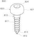
한편, 본 발명은 길이방향을 따라 연장되며 외주에 체결나사산이 형성되되, 일단부로 갈수록 원주방향을 따라 반경방향 내측으로 협소화되며, 일단부 반경방향 중심으로부터 길이방향 외측으로 첨단부가 일체로 돌출 형성되는 나사부; 및 상기 나사부의 타단부에 원주방향을 따라 반경방향 외측으로 절곡지게 확장된 외측단으로부터 상기 나사부의 길이방향을 따라 형성되는 수직측면부와, 단부에 형성되되 중앙부로부터 상기 나사부를 향하여 체결홈이 함몰 형성되는 평탄면부와, 상기 수직측면부 및 상기 평탄면부 사이에 테두리를 따라 라운드진 외면 윤곽으로 형성되는 라운드면부를 포함하여 구비되는 걸림고정용 헤드부를 포함하는 가이드픽싱스크류를 제공한다.Meanwhile, the present invention provides a guide fixing screw including a head portion for engaging and fixing, which includes a screw portion extending in the longitudinal direction and having a fastening screw thread formed on the outer periphery, narrowing radially inwardly along the circumference as it goes toward one end, and having a tip integrally formed to protrude outwardly in the longitudinal direction from the radial center of one end; and a vertical side portion formed along the longitudinal direction of the screw portion from an outer end that is bent radially outwardly along the circumference at the other end of the screw portion, a flat surface portion formed at the end and having a fastening groove sunk toward the screw portion from the center, and a round surface portion formed with a rounded outer contour along an edge between the vertical side portion and the flat surface portion.
상기의 해결 수단을 통하여, 본 발명은 다음과 같은 효과를 제공한다.Through the above solution, the present invention provides the following effects.
첫째, 치아수복물로서 제조된 서지컬 가이드의 정렬홈부 또는 임시보철의 임시걸림홈부가 걸림고정용 헤드부의 수직측면부에 형합되어 설치 후 진동 및 분리가 방지되므로 잇몸 리지가 낮은 무치악 환자의 구강에 식립된 가이드픽싱스크류에 설치되는 치아수복물의 위치가 정밀하게 유지되어 정확한 시술을 보장할 수 있다.First, the alignment groove of the surgical guide manufactured as a dental restoration or the temporary engaging groove of the temporary prosthesis is fitted into the vertical side of the engaging fixing head to prevent vibration and separation after installation, so that the position of the dental restoration installed on the guide fixing screw implanted in the oral cavity of an edentulous patient with a low gum ridge is precisely maintained, ensuring accurate treatment.
둘째, 서지컬 가이드의 정렬홈부 또는 임시보철의 임시걸림홈부가 걸림고정용 헤드부가 복수개 구비되는 경우에도 라운드진 외면 윤곽으로 형성된 라운드면부에 용이하게 안내 및 삽입된 후 수직측면부에 형합되므로 치아수복물의 설치편의성이 현저히 개선될 수 있다.Second, even when the alignment groove of the surgical guide or the temporary engagement groove of the temporary prosthesis is provided with multiple engagement fixing heads, the round surface formed by the rounded outer contour can be easily guided and inserted and then conformed to the vertical side surface, so the convenience of installing the dental restoration can be significantly improved.
셋째, 걸림고정용 헤드부에 대하여 획득된 헤드부 스캐닝이미지 및 헤드부 CT 이미지의 공통부분을 기준으로 스캐닝이미지와 CT 이미지를 중첩함에 따라 각 이미지가 신속하고 정확하게 정합될 수 있으며, 각 이미지 간의 형합도가 현저히 개선될 수 있다.Third, by overlapping the scanning image and the CT image based on the common portion of the head scanning image and the head CT image obtained for the head fixation, each image can be aligned quickly and accurately, and the degree of alignment between each image can be significantly improved.
도 1은 종래의 가이드픽싱스크류를 이용한 치아수복물 제조방법을 나타낸 흐름도.
도 2는 본 발명의 일실시예에 따른 가이드픽싱스크류를 이용한 치아수복물 제조방법을 나타낸 흐름도.
도 3은 본 발명의 일실시예에 따른 가이드픽싱스크류를 이용한 치아수복물 제조시스템을 나타낸 블록도.
도 4a는 본 발명의 일실시예에 따른 가이드픽싱스크류를 이용한 치아수복물 제조방법에서 가이드픽싱스크류가 식립된 식립대상부와 대합대상부를 정면에서 바라본 예시도.
도 4b는 본 발명의 일실시예에 따른 가이드픽싱스크류를 이용한 치아수복물 제조방법에서 가이드픽싱스크류가 식립된 식립대상부를 상면에서 바라본 예시도.
도 5a 및 도 5b는 본 발명의 일실시예에 따른 가이드픽싱스크류를 이용한 치아수복물 제조방법에서 CT 이미지 및 스캐닝이미지를 나타낸 예시도.
도 6은 본 발명의 일실시예에 따른 가이드픽싱스크류를 이용한 치아수복물 제조방법에서 3차원 플래닝이미지를 나타낸 예시도.
도 7은 본 발명의 일실시예에 따른 가이드픽싱스크류를 이용한 치아수복물 제조방법에서 가상 서지컬 가이드를 나타낸 예시도.
도 8은 도 7의 'A-B'방향 단면도.
도 9는 도 7의 'C-D'방향 단면도.
도 10은 본 발명의 일실시예에 따라 제조된 서지컬 가이드를 나타낸 단면도.
도 11은 본 발명의 일실시예에 따른 가이드픽싱스크류를 이용한 치아수복물 제조방법에서 가상 임시보철을 나타낸 예시도.
도 12는 본 발명의 일실시예에 따라 제조된 임시보철을 나타낸 예시도.
도 13은 본 발명의 일실시예에 따른 가이드픽싱스크류를 나타낸 정면도.
도 14는 본 발명의 일실시예에 따른 가이드픽싱스크류를 나타낸 사시도.Figure 1 is a flow chart showing a method for manufacturing a dental restoration using a conventional guide fixing screw.
Figure 2 is a flow chart showing a method for manufacturing a dental restoration using a guide fixing screw according to one embodiment of the present invention.
FIG. 3 is a block diagram showing a dental restoration manufacturing system using a guide fixing screw according to one embodiment of the present invention.
FIG. 4a is an exemplary view of a front view of a target portion and a target portion where a guide fixing screw is implanted in a method for manufacturing a dental restoration using a guide fixing screw according to one embodiment of the present invention.
FIG. 4b is an exemplary view of a top view of a target implantation site where a guide fixing screw is implanted in a method for manufacturing a dental restoration using a guide fixing screw according to one embodiment of the present invention.
FIGS. 5a and 5b are exemplary views showing CT images and scanning images in a method for manufacturing a dental restoration using a guide fixing screw according to one embodiment of the present invention.
FIG. 6 is an exemplary diagram showing a three-dimensional planning image in a method for manufacturing a dental restoration using a guide fixing screw according to an embodiment of the present invention.
FIG. 7 is an exemplary diagram showing a virtual surgical guide in a method for manufacturing a dental restoration using a guide fixing screw according to an embodiment of the present invention.
Fig. 8 is a cross-sectional view taken along the ‘A-B’ direction of Fig. 7.
Figure 9 is a cross-sectional view taken along the ‘C-D’ direction of Figure 7.
FIG. 10 is a cross-sectional view showing a surgical guide manufactured according to one embodiment of the present invention.
FIG. 11 is an exemplary diagram showing a virtual temporary prosthesis in a method for manufacturing a dental restoration using a guide fixing screw according to one embodiment of the present invention.
Figure 12 is an exemplary diagram showing a temporary prosthesis manufactured according to one embodiment of the present invention.
Figure 13 is a front view showing a guide fixing screw according to one embodiment of the present invention.
Figure 14 is a perspective view showing a guide fixing screw according to one embodiment of the present invention.
이하, 첨부된 도면을 참조하여 본 발명의 바람직한 실시예에 따른 가이드픽싱스크류 및 이를 이용한 치아수복물 제조방법을 상세히 설명한다.Hereinafter, with reference to the attached drawings, a guide fixing screw and a method for manufacturing a dental restoration using the same according to a preferred embodiment of the present invention will be described in detail.
도 2는 본 발명의 일실시예에 따른 가이드픽싱스크류를 이용한 치아수복물 제조방법을 나타낸 흐름도이고, 도 3은 본 발명의 일실시예에 따른 가이드픽싱스크류를 이용한 치아수복물 제조시스템을 나타낸 블록도이다. 그리고, 도 4a는 본 발명의 일실시예에 따른 가이드픽싱스크류를 이용한 치아수복물 제조방법에서 가이드픽싱스크류가 식립된 식립대상부와 대합대상부를 정면에서 바라본 예시도이며, 도 4b는 본 발명의 일실시예에 따른 가이드픽싱스크류를 이용한 치아수복물 제조방법에서 가이드픽싱스크류가 식립된 식립대상부를 상면에서 바라본 예시도이다. 그리고, 도 5a 및 도 5b는 본 발명의 일실시예에 따른 가이드픽싱스크류를 이용한 치아수복물 제조방법에서 CT 이미지 및 스캐닝이미지를 나타낸 예시도이고, 도 6은 본 발명의 일실시예에 따른 가이드픽싱스크류를 이용한 치아수복물 제조방법에서 3차원 플래닝이미지를 나타낸 예시도이다. 도 7은 본 발명의 일실시예에 따른 가이드픽싱스크류를 이용한 치아수복물 제조방법에서 가상 서지컬 가이드를 나타낸 예시도이며, 도 8은 도 7의 'A-B'방향 단면도이고, 도 9는 도 7의 'C-D'방향 단면도이다. 그리고, 도 10은 본 발명의 일실시예에 따라 제조된 서지컬 가이드를 나타낸 단면도이며, 도 11은 본 발명의 일실시예에 따른 가이드픽싱스크류를 이용한 치아수복물 제조방법에서 가상 임시보철을 나타낸 예시도이다. 그리고, 도 12는 본 발명의 일실시예에 따라 제조된 임시보철을 나타낸 예시도이며, 도 13은 본 발명의 일실시예에 따른 가이드픽싱스크류를 나타낸 정면도이다. 그리고, 도 14는 본 발명의 일실시예에 따른 가이드픽싱스크류를 나타낸 사시도이다.FIG. 2 is a flowchart showing a method for manufacturing a dental restoration using a guide fixing screw according to an embodiment of the present invention, and FIG. 3 is a block diagram showing a system for manufacturing a dental restoration using a guide fixing screw according to an embodiment of the present invention. In addition, FIG. 4a is an exemplary view showing a front view of an implantable portion and an opposing portion where a guide fixing screw is implanted in a method for manufacturing a dental restoration using a guide fixing screw according to an embodiment of the present invention, and FIG. 4b is an exemplary view showing a top view of an implantable portion where a guide fixing screw is implanted in a method for manufacturing a dental restoration using a guide fixing screw according to an embodiment of the present invention. And, FIGS. 5A and 5B are exemplary diagrams showing CT images and scanning images in a method for manufacturing a dental restoration using a guide fixing screw according to an embodiment of the present invention, and FIG. 6 is an exemplary diagram showing a three-dimensional planning image in a method for manufacturing a dental restoration using a guide fixing screw according to an embodiment of the present invention. FIG. 7 is an exemplary diagram showing a virtual surgical guide in a method for manufacturing a dental restoration using a guide fixing screw according to an embodiment of the present invention, and FIG. 8 is a cross-sectional view taken along the 'A-B' direction of FIG. 7, and FIG. 9 is a cross-sectional view taken along the 'C-D' direction of FIG. 7. And, FIG. 10 is a cross-sectional view showing a surgical guide manufactured according to an embodiment of the present invention, and FIG. 11 is an exemplary diagram showing a virtual temporary prosthesis in a method for manufacturing a dental restoration using a guide fixing screw according to an embodiment of the present invention. And, Fig. 12 is an exemplary view showing a temporary prosthesis manufactured according to one embodiment of the present invention, and Fig. 13 is a front view showing a guide fixing screw according to one embodiment of the present invention. And, Fig. 14 is a perspective view showing a guide fixing screw according to one embodiment of the present invention.
도 2 내지 도 14에서 보는 바와 같이, 본 발명의 일실시예에 따른 가이드픽싱스크류를 이용한 치아수복물 제조방법은 걸림고정용 헤드부가 형성된 적어도 하나 이상의 가이드픽싱스크류가 식립된 식립대상부 및 대합대상부에 대한 복수개의 스캐닝이미지와, 구강에 대한 CT 이미지 획득(s10), 스캐닝이미지 및 CT 이미지가 중첩 및 정합되어 교합높이가 고려된 3차원 플래닝이미지 생성(s20), 그리고 3차원 플래닝이미지를 기반으로 식립대상부의 치열라인에 대응되어 라운드지게 연장되되 일면을 따라 고정홈부가 함몰 형성되며 고정홈부로부터 정렬홈부가 함몰 형성되고 가이드홀이 관통 형성된 서지컬 가이드 설계 및 제조(s30), 3차원 플래닝이미지를 기반으로 임시보철 설계 및 제조(s40)의 일련의 단계를 포함한다. 이때, 본 발명에서 설명될 헤드부와 걸림고정용 헤드부는 동일한 개념으로 이해함이 바람직하다.As shown in FIGS. 2 to 14, a method for manufacturing a dental restoration using a guide fixing screw according to an embodiment of the present invention includes a series of steps of: acquiring a plurality of scanning images of a target implantation site and an opposing target implantation site, in which at least one guide fixing screw having a head portion for engaging and fixing is formed, and obtaining a CT image of the oral cavity (s10); overlapping and aligning the scanning images and the CT images to generate a three-dimensional planning image in which the occlusal height is considered (s20); designing and manufacturing a surgical guide that is extended in a rounded manner corresponding to the dentition line of the target implantation site based on the three-dimensional planning image, but in which a fixing groove portion is formed recessed along one surface, an alignment groove portion is formed recessed from the fixing groove portion, and a guide hole is formed penetrating therethrough (s30); and designing and manufacturing a temporary prosthesis based on the three-dimensional planning image (s40). At this time, it is preferable to understand that the head portion and the head portion for engaging and fixing to be described in the present invention have the same concept.
또한, 본 발명의 일실시예에 따른 서지컬 가이드 제조시스템은 촬상장치(901), 플래닝부(902) 및 제조장치(903)를 포함한다. 즉, 본 발명의 일실시예에 따른 가이드픽싱스크류를 이용한 치아수복물 제조방법은 상기 촬상장치(901), 상기 플래닝부(902) 및 상기 제조장치(903)를 포함하는 서지컬 가이드 제조시스템에 의해 수행될 수 있다.In addition, a surgical guide manufacturing system according to an embodiment of the present invention includes an imaging device (901), a planning unit (902), and a manufacturing device (903). That is, a method for manufacturing a dental restoration using a guide fixing screw according to an embodiment of the present invention can be performed by a surgical guide manufacturing system including the imaging device (901), the planning unit (902), and the manufacturing device (903).
한편, 임플란트 식립은 드릴을 이용하여 치조골에 천공을 형성하고, 상기 천공에 픽스츄어를 식립하는 과정으로 수행된다. 이때, 천공 작업을 수행할 정확한 위치 및 방향을 파악할 수 있도록 상기 서지컬 가이드(surgical guide)라고 하는 보조기구가 사용된다.Meanwhile, implant placement is performed by forming a hole in the alveolar bone using a drill and implanting a fixture into the hole. At this time, an auxiliary device called a surgical guide is used to determine the exact location and direction in which the drilling operation is to be performed.
즉, 피시술자의 구강 내부의 상태에 따라 임플란트 식립계획이 수립되면 수립된 임플란트 식립계획을 안내하는 상기 서지컬 가이드를 제작하여 시술자의 드릴작업 또는 픽스츄어 식립시 방향이나 깊이 등이 정확하게 가이드될 수 있다. 이때, 본 발명에서 치아수복물은 상기 서지컬 가이드(600) 및 임시보철(700)을 포함하는 개념으로 이해함이 바람직하다.That is, when an implant placement plan is established based on the condition inside the oral cavity of the recipient, the surgical guide that guides the established implant placement plan is manufactured so that the direction and depth, etc. of the drilling work or fixture placement of the recipient can be accurately guided. At this time, it is preferable to understand the dental restoration in the present invention as a concept that includes the surgical guide (600) and the temporary prosthesis (700).
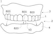
또한, 본 발명은 특히 상악 및 하악 중 적어도 어느 일측의 자연치아 소실량이 많아 수직고경(occlusal vertical dimension,VD)의 산출이 어려운 무치악 환자의 임플란트 식립시 응용될 수 있다. 특히, 본 발명은 잇몸 리지(Ridge)가 낮은 무치악 환자의 임플란트 식립시 응용될 수 있다. 이때, 상기 잇몸 리지라 함은 상악골 및 하악골에서 치아가 박혀있는 돌출구조로 이해함이 바람직하며, 상기 잇몸 리지는 치열궁에 대응하여 원호형으로 돌출 형성되는 치조골의 표면에 연조직인 잇몸(4)이 감싸진 해부학적 구조를 가진다.In addition, the present invention can be applied when implanting an edentulous patient who has lost a large amount of natural teeth on at least one side of the maxilla and the mandible, making it difficult to calculate the occlusal vertical dimension (VD). In particular, the present invention can be applied when implanting an edentulous patient who has a low gum ridge. At this time, it is preferable to understand the gum ridge as a protruding structure in which teeth are embedded in the maxilla and the mandible, and the gum ridge has an anatomical structure in which the gum (4), which is soft tissue, is wrapped around the surface of the alveolar bone that protrudes in an arc shape corresponding to the dental arch.
한편, 걸림고정용 헤드부(820)가 형성된 적어도 하나 이상의 가이드픽싱스크류(800)가 식립된 무치악의 식립대상부(2) 및 대합대상부(3)에 대한 복수개의 스캐닝이미지(111)와, 구강에 대한 CT 이미지(114)가 상기 촬상장치(901)를 통해 각각 획득되고 상기 플래닝부(902)로 전송된다(s10).Meanwhile, a plurality of scanning images (111) of the implantation target area (2) and the opposing target area (3) of the edentulous jaw, in which at least one guide fixing screw (800) having a fixing head (820) formed thereon is implanted, and a CT image (114) of the oral cavity are each acquired through the imaging device (901) and transmitted to the planning unit (902) (s10).
여기서, 상기 가이드픽싱스크류(800)는 체결나사산(811)이 형성된 나사부(810)의 단부에 원주방향을 따라 반경방향 외측으로 절곡지게 확장된 외측단으로부터 길이방향을 따라 형성된 수직측면부(821) 및 체결홈(824)이 함몰 형성된 평탄면부(822) 사이에 라운드진 외면 윤곽으로 형성되는 라운드면부(823)가 형성된 걸림고정용 헤드부(820)를 포함하여 구비됨이 바람직하다.Here, it is preferable that the guide fixing screw (800) is provided with a head portion (820) for engaging and fixing, which includes a vertical side portion (821) formed along the longitudinal direction from an outer end that is bent radially outwardly along the circumferential direction at the end of a screw portion (810) in which a fastening screw thread (811) is formed, and a round surface portion (823) formed with a rounded outer surface contour between a flat surface portion (822) in which a fastening groove (824) is formed sunken.
또한, 상기 식립대상부(2)는 피시술자의 구강 내부(1)의 상악 또는 하악 중 어느 일측에 자연치아가 상실되어 임플란트 식립을 수행하고자 하는 부분으로, 특히 상기 대합대상부(3)의 단부(t)와의 대향단부측으로 이해함이 바람직하다.In addition, the implant target area (2) is a portion of the oral cavity (1) of the patient where a natural tooth is lost on either the upper or lower jaw and where implant implantation is to be performed, and it is preferable to understand it as the end portion opposite to the end portion (t) of the opposing target area (3).
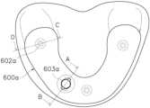
그리고, 도 4a 내지 도 4b를 참조하면, 상기 가이드픽싱스크류(800)는 상기 식립대상부(2)에 적어도 하나 이상 식립된다. 이때, 본 발명의 일실시예에서 상기 가이드픽싱스크류(800)는 상기 식립대상부(2)에 상호간 간격을 두고 이격되며 3개소 식립되는 경우를 예로써 도시 및 설명한다. 또한, 각 상기 가이드픽싱스크류(800)는 상기 나사부(810)가 상기 식립대상부(2)에 셀프 탭핑되며 식립되되 상기 나사부(810)의 단부에 형성된 상기 걸림고정용 헤드부(820)가 상기 식립대상부(2)로부터 돌출되어 노출 배치된다. 상기 가이드픽싱스크류(800)의 상세한 형상은 후술된다.And, referring to FIGS. 4A and 4B, at least one guide fixing screw (800) is implanted in the implantation target portion (2). At this time, in one embodiment of the present invention, a case in which the guide fixing screws (800) are implanted in three places with a gap therebetween in the implantation target portion (2) is illustrated and described as an example. In addition, each of the guide fixing screws (800) is implanted by self-tapping the screw portion (810) in the implantation target portion (2), and the head portion (820) for fixing formed at the end of the screw portion (810) protrudes from the implantation target portion (2) and is exposed. The detailed shape of the guide fixing screw (800) will be described later.
또한, 상기 가이드픽싱스크류(800) 중 어느 하나는 상기 식립대상부(2)의 전치측 중앙부에 식립될 수 있으며, 상기 가이드픽싱스크류(800) 중 나머지 2개는 상기 식립대상부(2)의 각 구치부에 상호 대칭되는 위치로 식립될 수 있다. 또한, 상기 가이드픽싱스크류(800)의 식립 위치는 픽스츄어의 식립 위치(6)로부터 이격 배치됨이 바람직하다. 이때, 도 4b에서 6으로 도시된 영역은 상기 식립대상부(2)에 픽스츄어(f)가 식립될 위치로 이해함이 바람직하다.In addition, one of the above guide fixing screws (800) can be implanted in the central portion of the anterior side of the implantation target portion (2), and the remaining two of the above guide fixing screws (800) can be implanted in mutually symmetrical positions in each molar portion of the implantation target portion (2). In addition, it is preferable that the implantation position of the above guide fixing screw (800) be spaced apart from the implantation position (6) of the fixture. At this time, it is preferable to understand that the area indicated by 6 in FIG. 4b is the position where the fixture (f) is implanted in the implantation target portion (2).
한편, 상기 수직고경(VD)의 획득을 위한 수직고경측정장치(미도시)가 상기 피시술자의 저작감도에 따라 상기 수직고경(VD)이 고려된 상태로 상기 구강 내부(1)에 배치될 수 있다. 이때, 상기 수직고경측정장치(미도시)는 상기 식립대상부(2) 및 상기 대합대상부(3) 사이에 형성되는 교합공간에 수직고경(VD)이 고려되어 구비된다. 이때, 상기 수직고경측정장치(미도시)는 피시술자의 저작감도에 따라 상기 식립대상부(2) 및 상기 대합대상부(3)의 각 대향단부에 의해 가압되며, 상하면에 상기 각 대향단부의 외면 윤곽과 대응되는 형합홈부 및 걸림홈부가 함몰 형성될 수 있다. 그리고, 상기 교합공간은 피시술자의 개략적인 수직고경(VD)이 해부학적으로 예측됨에 따라 상기 대합대상부(3)의 단부(t)와 상기 식립대상부(2)의 대향단부 사이에 임의로 산출되어 이격되는 빈공간으로 이해함이 바람직하다. 이때, 상기 수직고경(VD)은 상기 수직고경측정장치(미도시)에 가해지는 교합력(bite force)에 의해 함몰 형성된 형합홈부와 걸림홈부 사이의 간격에 대응하되, 피시술자의 저작감도에 따라 최적화되어 설정될 수 있다. 이러한 저작감도는 피시술자의 직접적인 의사표현에 의해 판단될 수 있으며, 경우에 따라 턱관절 주변 및 턱근육의 전기적, 화학적 신호를 측정하여 판단할 수도 있다.Meanwhile, a vertical diameter measuring device (not shown) for obtaining the vertical diameter (VD) may be placed inside the oral cavity (1) in consideration of the vertical diameter (VD) according to the masticatory sensitivity of the subject. At this time, the vertical diameter measuring device (not shown) is provided in consideration of the vertical diameter (VD) in the occlusal space formed between the implantation target portion (2) and the opposing target portion (3). At this time, the vertical diameter measuring device (not shown) is pressed by the opposing ends of the implantation target portion (2) and the opposing target portion (3) according to the masticatory sensitivity of the subject, and a shaping groove portion and a catch groove portion may be formed on the upper and lower surfaces corresponding to the outer surface contours of the opposing ends. And, it is preferable to understand the occlusal space as an empty space arbitrarily calculated and spaced between the end (t) of the opposing portion (3) and the opposite end of the implantation portion (2) according to the anatomical prediction of the approximate vertical dimension (VD) of the subject. At this time, the vertical dimension (VD) corresponds to the gap between the mating groove and the engaging groove formed by the bite force applied to the vertical dimension measuring device (not shown), but can be optimally set according to the masticatory sensitivity of the subject. This masticatory sensitivity can be determined by the direct expression of the subject's will, and in some cases, can be determined by measuring the electrical and chemical signals around the temporomandibular joint and jaw muscles.
따라서, 상기 수직고경측정장치(미도시)가 설치된 상태에서 상기 식립대상부(2)와 상기 대합대상부(3)의 단부는 상기 수직고경(VD)에 대응하여 이격될 수 있다. 이를 통해, 상기 수직고경측정장치(미도시)이 설치된 구강 내부를 스캔하여 획득된 상기 스캐닝이미지(111)에는 상기 식립대상부 및 상기 대합대상부의 대향단부(2b,t)가 상기 수직고경(VD)에 대응하여 이격된 상태의 외형정보가 포함될 수 있다.Accordingly, when the vertical height measuring device (not shown) is installed, the ends of the implantation target portion (2) and the opposing target portion (3) can be spaced apart in correspondence to the vertical height (VD). Accordingly, the scanning image (111) obtained by scanning the inside of the oral cavity in which the vertical height measuring device (not shown) is installed can include external shape information of the opposing ends (2b,t) of the implantation target portion and the opposing target portion being spaced apart in correspondence to the vertical height (VD).
한편, 상기 수직고경측정장치(미도시)가 설치되어 교합된 구강 내부(1)를 CT 촬영하여 상기 CT 이미지(114)가 획득된다. 이때, 상기 CT 이미지(114)는 치조골 형상, 골밀도 등과 같은 피시술자의 구강 내부(1)에 대한 2차원 및 3차원적인 내부 조직 정보를 포함한다.Meanwhile, the vertical height measuring device (not shown) is installed, and the inside of the occluded oral cavity (1) is CT-photographed to obtain the CT image (114). At this time, the CT image (114) includes two-dimensional and three-dimensional internal tissue information about the inside of the oral cavity (1) of the subject, such as the shape of the alveolar bone and bone density.
또한, 도 5a를 참조하면, 상기 CT 이미지(114)는 상기 걸림고정용 헤드부(820)가 형성된 상기 가이드픽싱스크류(800)의 외면 형상에 대한 2차원 및 3차원적인 헤드부 CT 이미지(25a)를 포함하는 가이드픽싱스크류 CT 이미지(25)를 포함한다. 여기서, 상기 CT 이미지(114)는 상기 식립대상부(2)의 각 구치측으로부터 돌출된 상기 걸림고정용 헤드부(820)의 외면 형상에 대한 구치측 헤드부 CT 이미지와, 상기 식립대상부(2)의 전치측 중앙부로부터 돌출된 상기 걸림고정용 헤드부(820)의 외면 형상에 대한 전치측 헤드부 CT 이미지를 포함하여 획득될 수 있다. 이때, 상기 걸림고정용 헤드부(820)가 형성된 상기 가이드픽싱스크류(800)는 방사선 불투과성 재질로 구비될 수 있으며, 바람직하게는 티타늄과 같은 금속 재질로 구비될 수 있다.In addition, referring to FIG. 5a, the CT image (114) includes a guide fixing screw CT image (25) including two-dimensional and three-dimensional head CT images (25a) of the outer surface shape of the guide fixing screw (800) on which the engaging and fixing head portion (820) is formed. Here, the CT image (114) can be obtained by including a molar-side head portion CT image of the outer surface shape of the engaging and fixing head portion (820) protruding from each molar side of the implantation target portion (2) and an anterior-side head portion CT image of the outer surface shape of the engaging and fixing head portion (820) protruding from the anterior-side central portion of the implantation target portion (2). At this time, the guide fixing screw (800) on which the engaging and fixing head portion (820) is formed can be formed of a radiopaque material, and preferably can be formed of a metal material such as titanium.
더욱이, 상기 CT 이미지(114)가 상기 수직고경측정장치(미도시)가 설치된 상태에서 획득되면 상기 식립대상부측의 치조골(2a)과 상기 대합대상부측 단부(t) 사이가 수직고경(VD)에 대응하여 이격된 상태로 표시될 수 있다.Furthermore, when the CT image (114) is acquired with the vertical dimension measuring device (not shown) installed, the distance between the alveolar bone (2a) on the implantation target side and the end (t) on the opposing target side can be displayed as being spaced apart in accordance with the vertical dimension (VD).
즉, 상기 CT 이미지(114)에 포함된 2차원 및 3차원 내부 조직 정보는 이미 수직고경(VD)이 고려된 상태로 획득되므로 임플란트 식립계획을 위한 수직고경(VD)에 대한 정보가 상기 CT 이미지(114)로부터 손쉽게 획득될 수 있다. 또한, 상기 CT 이미지(114)의 이미지 보정작업이 실질적으로 생략 가능함에 따라 종래에 수직고경이 고려되지 않고 획득된 CT 이미지를 피시술자의 수직고경에 대응되도록 보정하던 복잡한 과정이 간소화될 수 있다.That is, since the two-dimensional and three-dimensional internal tissue information included in the CT image (114) is already acquired with the vertical dimension (VD) taken into consideration, information on the vertical dimension (VD) for implant placement planning can be easily acquired from the CT image (114). In addition, since the image correction work of the CT image (114) can be practically omitted, the complicated process of correcting a CT image acquired without considering the vertical dimension to correspond to the vertical dimension of the patient in the past can be simplified.
이때, 상기 수직고경측정장치(미도시)는 방사선 투과성의 수지 재질이 상기 교합공간 일측에 부분적으로 충진되어 구비될 수 있다. 즉, 상기 CT 이미지(114)에 표시된 상기 식립대상부측 치조골(2a)과 상기 대합대상부측 단부(t)는 상기 수직고경(VD)에 대응하여 이격되면서도 상기 부분교합레진에 대한 이미지는 상기 CT 이미지(114)에 실질적으로 표시되지 않는다.At this time, the vertical dimension measuring device (not shown) may be provided with a radiolucent resin material partially filling one side of the occlusal space. That is, the alveolar bone (2a) on the implantation target side and the end (t) on the opposing target side, which are indicated in the CT image (114), are spaced apart in correspondence to the vertical dimension (VD), but the image for the partial occlusal resin is not substantially displayed in the CT image (114).
한편, 상기 식립대상부(2) 및 상기 대합대상부(3)에 대한 상기 스캐닝이미지(111)가 획득됨이 바람직하다. 상세히, 상기 스캐닝이미지(111)는 피시술자의 구강 내부에 대한 3차원 외형정보가 포함되며, 구강스캐너를 포함하여 구비된 상기 촬상장치(901)를 이용하여 피시술자의 구강 내부를 직접 스캐닝하여 획득될 수 있다. 즉, 상기 촬상장치(901)는 상기 식립대상부(2) 및 상기 대합대상부(3)의 외면에 대한 3차원 표면정보를 획득하는 구강스캐너 및 상하악의 골형상, 치조골 밀도 등에 대한 내부정보를 획득하는 컴퓨터단층촬영기를 포괄하는 개념으로 이해함이 바람직하다.Meanwhile, it is preferable to obtain the scanning image (111) of the implantation target portion (2) and the opposing target portion (3). In detail, the scanning image (111) includes three-dimensional external information about the inside of the oral cavity of the subject, and can be obtained by directly scanning the inside of the oral cavity of the subject using the imaging device (901) equipped with an oral scanner. That is, it is preferable to understand the imaging device (901) as a concept encompassing an oral scanner that obtains three-dimensional surface information about the outer surfaces of the implantation target portion (2) and the opposing target portion (3), and a computed tomography machine that obtains internal information about the bone shape of the upper and lower jaws, alveolar bone density, etc.
그리고, 상기 스캐닝이미지(111)는 상기 수직고경(VD)에 대응하여 이격된 상기 식립대상부와 상기 대합대상부의 대향단부(2b,t) 및 상기 수직고경측정장치(미도시)의 외면형상을 포함하는 상기 교합 스캐닝이미지(111c)를 포함하여 획득됨이 바람직하다.And, it is preferable that the scanning image (111) be acquired including the occlusal scanning image (111c) including the outer surface shape of the vertical dimension measuring device (not shown) and the opposing end portions (2b,t) of the implantation target portion and the opposing target portion spaced apart in correspondence to the vertical dimension (VD).
상세히, 도 5b를 참조하면, 상기 교합 스캐닝이미지(111c)에는 상기 식립대상부 및 상기 대합대상부의 3차원 외형정보가 표시된다. 이때, 상기 교합 스캐닝이미지(111c)는 상기 식립대상부 및 상기 대합대상부의 대향단부(2b,t)가 상기 수직고경(VD)에 대응하여 이격된 상태로 표시될 수 있다.In detail, referring to Fig. 5b, the occlusal scanning image (111c) displays three-dimensional external information of the implantation target portion and the opposing target portion. At this time, the occlusal scanning image (111c) may display the opposing ends (2b, t) of the implantation target portion and the opposing target portion spaced apart in correspondence with the vertical dimension (VD).
그리고, 상기 스캐닝이미지(111)는 상기 식립대상부 및 상기 대합대상부의 외면형상을 각각 포함하는 식립측 스캐닝이미지(111a) 및 대합측 스캐닝이미지(111b)를 더 포함하여 획득될 수 있다. 그리고, 상기 식립측 스캐닝이미지(111a) 및 상기 대합측 스캐닝이미지(111b)가 상기 교합 스캐닝이미지(111c)를 기반으로 예비정합될 수도 있다.In addition, the scanning image (111) may be obtained by further including an implantation-side scanning image (111a) and an opposing-side scanning image (111b) which each include the outer surface shapes of the implantation target portion and the opposing target portion. In addition, the implantation-side scanning image (111a) and the opposing-side scanning image (111b) may be pre-aligned based on the occlusal scanning image (111c).
상세히, 상기 식립측 스캐닝이미지(111a)는 상기 식립대상부 및 잇몸에 대한 3차원 외형정보가 포함되고 상기 대합측 스캐닝이미지(111b)는 대합대상부의 단부(t) 및 저작면 등의 3차원 외형정보가 포함된다.In detail, the above-mentioned implant-side scanning image (111a) includes three-dimensional external information about the implant target area and gums, and the above-mentioned opposing-side scanning image (111b) includes three-dimensional external information about the end (t) of the opposing target area and the chewing surface.
그리고, 상기 식립측 스캐닝이미지(111a)는 상기 식립대상부(2)의 외면 형상에 대한 식립대상이미지(4a) 및 상기 식립대상부(2)로부터 돌출된 상기 걸림고정용 헤드부(820)의 외면 형상에 대한 헤드부 스캐닝이미지(15a)를 포함하여 획득됨이 바람직하다. 이때, 상기 헤드부 스캐닝이미지(15a)는 상기 가이드픽싱스크류(800)가 상기 식립대상부(2)의 외측으로 부분 노출된 영역의 외면 형상에 대하여 획득되는 가이드픽싱스크류 스캐닝이미지(15)에 포함되는 개념으로 이해함이 바람직하다. 또한, 상기 식립대상부(2)에 식립된 상기 가이드픽싱스크류(800)의 나사부(810)는 노출되지 않으므로 스캐닝이미지가 미획득됨으로 이해함이 바람직하다. 더불어, 상기 식립대상이미지(4a)는 상기 식립측 스캐닝이미지(111a)에서 상기 가이드픽싱스크류 스캐닝이미지(15)를 제외한 이미지로 이해함이 바람직하다. 즉, 상기 식립대상이미지(4a)는 상기 식립대상부(도 4a의 2)의 외면 윤곽에 대한 이미지로 이해함이 바람직하다.And, it is preferable that the above-mentioned implantation-side scanning image (111a) is acquired including the implantation target image (4a) for the outer surface shape of the implantation target portion (2) and the head scanning image (15a) for the outer surface shape of the head portion (820) for hooking and fixing protruded from the implantation target portion (2). At this time, it is preferable to understand that the head scanning image (15a) is included in the guide fixing screw scanning image (15) acquired for the outer surface shape of the area where the guide fixing screw (800) is partially exposed to the outside of the implantation target portion (2). In addition, it is preferable to understand that the screw portion (810) of the guide fixing screw (800) implanted in the implantation target portion (2) is not exposed and therefore the scanning image is not acquired. In addition, it is preferable to understand the above-mentioned implantation target image (4a) as an image obtained by excluding the guide fixing screw scanning image (15) from the above-mentioned implantation-side scanning image (111a). That is, it is preferable to understand the above-mentioned implantation target image (4a) as an image of the outer surface outline of the above-mentioned implantation target portion (2 in FIG. 4a).
여기서, 상기 스캐닝이미지(111)에 포함된 상기 식립측 스캐닝이미지(111a)는 상기 식립대상부(2)의 각 구치측으로부터 돌출된 상기 걸림고정용 헤드부(820)의 외면 형상에 대한 구치측 헤드부 스캐닝이미지와, 상기 식립대상부(2)의 전치측 중앙부로부터 돌출된 상기 걸림고정용 헤드부(820)의 외면 형상에 대한 전치측 헤드부 스캐닝이미지를 포함하여 획득될 수 있다.Here, the implantation-side scanning image (111a) included in the scanning image (111) can be obtained by including a molar-side head scanning image for the outer surface shape of the hook-and-fix head part (820) protruding from each molar side of the implantation target part (2), and an anterior-side head scanning image for the outer surface shape of the hook-and-fix head part (820) protruding from the anterior-side central part of the implantation target part (2).
그리고, 상기 식립측 스캐닝이미지(111a) 및 상기 대합측 스캐닝이미지(111b)는 상기 교합 스캐닝이미지(111c)와 기설정된 공통부분을 기준으로 정렬될 수도 있다. 이때, 상기 교합 스캐닝이미지(111c)는 피시술자의 수직고경(VD)이 고려된 상태의 외형정보를 포함한다. 따라서, 상기 식립측 스캐닝이미지(111a)와 상기 대합측 스캐닝이미지(111b)가 상기 교합 스캐닝이미지(111c)를 기준으로 예비정합되면 상기 식립측 스캐닝이미지(111a) 및 상기 대합측 스캐닝이미지(111b)가 피시술자의 수직고경(VD)에 대응하여 배치될 수 있다. 이러한 상기 CT 이미지(114) 및 상기 스캐닝이미지(111)는 영상 정합, 보정 및 설계작업이 용이하도록 3차원 벡터 데이터로 저장될 수 있다.And, the implantation-side scanning image (111a) and the opposing-side scanning image (111b) may be aligned with the common portion set with the occlusal scanning image (111c). At this time, the occlusal scanning image (111c) includes external information in which the vertical dimension (VD) of the subject is taken into consideration. Therefore, when the implantation-side scanning image (111a) and the opposing-side scanning image (111b) are pre-aligned with the occlusal scanning image (111c) as the basis, the implantation-side scanning image (111a) and the opposing-side scanning image (111b) may be arranged corresponding to the vertical dimension (VD) of the subject. The CT image (114) and the scanning image (111) may be stored as three-dimensional vector data to facilitate image alignment, correction, and design work.
한편, 상기 스캐닝이미지(111) 및 상기 CT 이미지(114)에 표시된 공통부분을 기준으로 중첩 및 본정합되어 교합높이, 즉 상기 수직고경(VD)이 고려된 3차원 플래닝이미지(116)가 상기 플래닝부(920)에 의해 생성된다(s20). 이때, 상기 플래닝부(920)는 상기 촬상장치(910)를 이용하여 획득된 이미지데이터 및 기저장된 설계정보를 바탕으로 상기 서지컬 가이드와 인공치아부를 설계하는 설계장치로 이해함이 바람직하다.Meanwhile, a three-dimensional planning image (116) is generated by the planning unit (920) based on the common portions indicated in the scanning image (111) and the CT image (114), and the occlusal height, i.e., the vertical dimension (VD), is considered by overlapping and matching them (s20). At this time, it is preferable to understand the planning unit (920) as a design device that designs the surgical guide and the artificial tooth based on the image data acquired using the imaging device (910) and the pre-stored design information.
여기서, 도 6을 참조하면, 상기 3차원 플래닝이미지(116)는 상기 헤드부 중첩정합이미지를 기준으로 상기 스캐닝이미지(111)와 상기 CT 이미지(114)가 상기 플래닝부(920)에 의해 중첩 및 정합되어 헤드부 중첩정합이미지가 생성됨이 바람직하다. 즉, 상기 스캐닝이미지(111)와 상기 CT 이미지(114)는 상기 헤드부 중첩정합이미지를 마커로서 상기 플래닝부(920)에 의해 중첩 및 정합될 수 있다. 이때, 상기 헤드부 중첩정합이미지는 상기 헤드부 스캐닝이미지(15a) 및 상기 헤드부 CT 이미지(25a)가 상기 플래닝부(920)에 의해 중첩 정합되어 생성됨이 바람직하다. 즉, 상기 3차원 플래닝이미지(116)에는 상기 헤드부 스캐닝이미지(15a) 및 상기 헤드부 CT 이미지(25a)가 중첩 정합되어 생성된 상기 헤드부 중첩정합이미지가 포함됨이 바람직하다. 이때, 상기 헤드부 중첩정합이미지는 도 6에서 15a(25a)로 도시된 부분 및 도 9에서 15a로 도시된 부분으로 이해함이 바람직하다.Here, referring to FIG. 6, it is preferable that the 3D planning image (116) is generated by overlapping and aligning the scanning image (111) and the CT image (114) by the planning unit (920) based on the head overlapping alignment image. That is, the scanning image (111) and the CT image (114) can be overlapped and aligned by the planning unit (920) using the head overlapping alignment image as a marker. At this time, it is preferable that the head overlapping alignment image is generated by overlapping and aligning the head scanning image (15a) and the head CT image (25a) by the planning unit (920). That is, it is preferable that the three-dimensional planning image (116) includes the head overlapping aligned image generated by overlapping and aligned the head scanning image (15a) and the head CT image (25a). At this time, it is preferable to understand the head overlapping aligned image as the portion illustrated as 15a (25a) in FIG. 6 and the portion illustrated as 15a in FIG. 9.
따라서, 상기 플래닝부(920)가 상기 스캐닝이미지(111) 및 상기 CT 이미지(114)의 공통부분인 상기 헤드부 스캐닝이미지(15a) 및 상기 헤드부 CT 이미지(25a)를 기준으로 상기 스캐닝이미지(111)와 상기 CT 이미지(114)를 중첩함에 따라 각 이미지(111,114)가 신속하고 정확하게 정합될 수 있으며, 각 이미지(111,114) 간의 형합도가 더욱 개선될 수 있다.Accordingly, as the planning unit (920) overlaps the scanning image (111) and the CT image (114) based on the head scanning image (15a) and the head CT image (25a), which are common parts of the scanning image (111) and the CT image (114), each image (111, 114) can be aligned quickly and accurately, and the degree of alignment between each image (111, 114) can be further improved.
상세히, 상기 3차원 플래닝이미지(116)에는 상기 CT 이미지(114)로부터 제공되는 피시술자의 구강 내부에 대한 2차원 및 3차원 내부 조직 정보가 포함된다. 더불어, 상기 스캐닝이미지(111)로부터 제공되는 구강 내부의 3차원 외형정보가 통합되어 포함된다. 이에 따라, 임플란트 식립물 및 상기 식립물의 식립위치를 정확하게 가이드할 수 있는 상기 서지컬 가이드의 설계정보가 상기 3차원 플래닝이미지(116)를 통하여 전반적으로 획득될 수 있다. 이를 통해, 임플란트 식립계획의 정확도가 향상될 수 있으며 임플란트 식립계획과 동시에 상기 식립물 및 상기 서지컬 가이드의 설계가 용이하므로 신속하면서도 정밀한 임플란트 식립이 수행될 수 있다.In detail, the three-dimensional planning image (116) includes two-dimensional and three-dimensional internal tissue information about the inside of the oral cavity of the subject provided from the CT image (114). In addition, three-dimensional external shape information about the inside of the oral cavity provided from the scanning image (111) is integrated and included. Accordingly, design information of the surgical guide capable of accurately guiding the implant placement material and the placement position of the implant placement material can be acquired overall through the three-dimensional planning image (116). Through this, the accuracy of the implant placement plan can be improved, and since the design of the implant placement material and the surgical guide can be easily performed at the same time as the implant placement plan, rapid and precise implant placement can be performed.
여기서, 상기 스캐닝이미지(111) 및 상기 CT 이미지(114)는 피시술자의 수직고경(VD)이 이미 고려된 상태로 획득되므로 이미지 영상 정합의 정확도가 개선될 수 있다. 더욱이, 상기 CT 이미지(114)는 치열 곡률 또한 실질적으로 피시술자의 구강 내부에 대응하여 획득될 수 있다. 따라서, 상기 CT 이미지(114)의 보정작업이 실질적으로 생략될 수 있으며, 상기 CT 이미지(114)를 기준으로 상기 스캐닝이미지(111)의 왜곡된 치열 곡률이 보정되는 최소한의 작업으로 간소화될 수 있다.Here, since the scanning image (111) and the CT image (114) are acquired in a state in which the vertical dimension (VD) of the subject is already taken into consideration, the accuracy of image alignment can be improved. Furthermore, the CT image (114) can be acquired so that the curvature of the teeth substantially corresponds to the inside of the oral cavity of the subject. Therefore, the correction work of the CT image (114) can be substantially omitted, and the work of correcting the distorted curvature of the scanning image (111) based on the CT image (114) can be simplified to a minimum.
이에 따라, 피시술자의 구강 내부와 실질적으로 대응되는 3차원 플래닝이미지(116)가 신속하면서도 정밀하게 획득될 수 있다. 그리고, 상기 3차원 플래닝이미지(116)를 기반으로 설계 및 제조되는 상기 식립물 및 상기 서지컬 가이드의 신뢰도가 향상되므로 임플란트 식립의 정확도가 현저히 개선될 수 있다.Accordingly, a three-dimensional planning image (116) substantially corresponding to the inside of the oral cavity of the recipient can be quickly and precisely acquired. In addition, since the reliability of the implant and the surgical guide designed and manufactured based on the three-dimensional planning image (116) is improved, the accuracy of implant placement can be significantly improved.
이때, 대합대상부측의 경우 상기 CT 이미지(114)와 상기 스캐닝이미지(111)에 표시된 대합대상부의 단부(t) 및 저작면 등의 견고한 조직에 대한 외면형상이 공통부분으로 표시되며, 이를 기준으로 중첩하고 비교영역으로 설정된다. 그리고, 상기 비교영역은 각 이미지에 표시되는 공통부분에서 상호 대응되는 점, 선 내지 면으로 설정될 수 있다. 더욱이, 상기 비교영역을 복수개소로 지정함에 따라 상기 CT 이미지(114)와 상기 스캐닝이미지(111) 간의 형합도가 현저히 개선될 수 있다.At this time, in the case of the target area side, the outer surface shape of the solid tissue such as the end (t) of the target area and the masticatory surface displayed in the CT image (114) and the scanning image (111) is displayed as a common part, and is overlapped based on this and set as a comparison area. In addition, the comparison area can be set as a point, line, or plane that corresponds to each other in the common part displayed in each image. Furthermore, by designating the comparison area as a plurality of locations, the degree of conformity between the CT image (114) and the scanning image (111) can be significantly improved.
더욱이, 상기 스캐닝이미지(111)와 상기 CT 이미지(114)가 상기 수직고경측정장치(미도시)가 설치된 상태로 획득됨에 따라 실질적으로 동일한 수직고경(VD)에 대응하여 이격된 상기 식립대상부와 상기 대합대상부측 정보를 포함한다. 따라서, 상기 스캐닝이미지(111) 및 상기 CT 이미지(114)의 공통부분인 상기 대합대상부의 단부(t) 및 저작면 등을 공통부분으로 하여 중첩함에 따라 각 이미지(111,114)가 신속하고 정확하게 정합될 수도 있다.Furthermore, since the scanning image (111) and the CT image (114) are acquired with the vertical dimension measuring device (not shown) installed, they include information on the implantation target portion and the opposing target portion that are spaced apart from each other in correspondence to substantially the same vertical dimension (VD). Accordingly, since the common portions of the scanning image (111) and the CT image (114), such as the end portion (t) and the masticatory surface of the opposing target portion, are overlapped as the common portions, each image (111, 114) can be quickly and accurately aligned.
한편, 각 비교영역의 최상단부 및 최외곽부가 일치되도록 상기 스캐닝이미지(111)를 상기 CT 이미지(114)에 대응하여 보정하는 단계가 수행된다. 상세히, 각 이미지(111,114)의 공통부분이 설정된 각 비교영역이 쌍으로 매칭되면, 각 쌍의 비교영역을 중첩하여 형합오차가 적은 최초의 디퍼런스 맵이 획득될 수 있다. 그리고, 최초의 디퍼런스 맵을 통한 영상 정합 과정에서 이미지 보정작업을 수행하여 고도로 정밀화되어 형합도가 높은 상기 3차원 플래닝이미지(116)가 획득될 수 있다. 여기서, 상기 형합도는 상기 CT 이미지(114)와 상기 스캐닝이미지(111)의 유사한 정도를 두 이미지 사이의 형합오차로 나타낸 것을 의미한다. 상세히, 상기 형합오차의 절대값이 낮을수록 두 이미지는 서로 형합되어 정확하게 중첩되는 것을 의미하며 형합도가 높다고 해석할 수 있다. 반대로, 상기 형합오차의 절대값이 높을수록 두 이미지는 어긋나게 중첩된 것을 의미한다. 즉, 형합오차가 0인 경우 상기 형합도는 가장 높으며, 형합오차의 절대값에 비례하여 상기 형합도가 낮아진다.Meanwhile, a step of correcting the scanning image (111) to correspond to the CT image (114) so that the uppermost part and the outermost part of each comparison area match is performed. In detail, when each comparison area in which the common part of each image (111, 114) is set is matched in pairs, the comparison areas of each pair can be overlapped to obtain an initial difference map with a small merging error. Then, an image correction operation can be performed in the image matching process through the initial difference map to obtain the three-dimensional planning image (116) with high precision and high merging degree. Here, the merging degree means the degree of similarity between the CT image (114) and the scanning image (111) expressed as the merging error between the two images. In detail, the lower the absolute value of the merging error, the more accurately the two images are merging and overlapping with each other, which can be interpreted as a high merging degree. Conversely, the higher the absolute value of the above-mentioned mismatch error, the more the two images are misaligned and overlapped. That is, when the above-mentioned mismatch error is 0, the above-mentioned mismatch degree is the highest, and the above-mentioned mismatch degree decreases in proportion to the absolute value of the above-mentioned mismatch error.
그리고, 상기 각 이미지(111,114)에 비교영역으로 설정된 공통부분의 형합도가 높아짐에 따라 실질적으로 상기 스캐닝이미지(111)와 상기 CT 이미지(114)의 상호 대응되는 부분의 형합도 역시 높아짐으로 해석할 수 있다. 예컨대, 상기 형합도는 상기 비교영역으로 설정된 공통부분을 기준으로 상기 CT 이미지(114)와 상기 스캐닝이미지(111)를 중첩시, 어느 일측 이미지의 표면으로부터 타측 이미지의 표면이 돌출 또는 함몰된 정도로 나타날 수 있다. 더욱이, 상기 형합도는 상기 각 이미지(111,114)의 3차원 벡터 데이터를 통해 산출될 수 있다. 즉, 상기 각 이미지(111,114)의 3차원 벡터 데이터를 통해 상기 각 이미지(111,114)의 표면의 높이 정보가 수치로 표현될 수 있다. 이러한 형합도는 수치와 함께 색상별로 분해하여 출력됨에 따라 시술자가 영상 정합 결과에 대한 정확성을 신속하고 직관적으로 판단할 수 있다. 이를 통해, 신속한 이미지 연산처리가 가능하며, 정밀한 3차원 플래닝이미지(116)의 획득을 위한 후속 보정작업이 원활하게 진행될 수 있다.And, as the degree of conformity of the common part set as the comparison area in each of the images (111, 114) increases, the degree of conformity of the corresponding parts of the scanning image (111) and the CT image (114) also increases. For example, the degree of conformity may be expressed as the degree to which the surface of one image protrudes or sinks from the surface of the other image when the CT image (114) and the scanning image (111) are overlapped based on the common part set as the comparison area. Furthermore, the degree of conformity may be calculated through the three-dimensional vector data of each of the images (111, 114). That is, the height information of the surface of each of the images (111, 114) may be expressed in numbers through the three-dimensional vector data of each of the images (111, 114). Since the degree of conformity is output by decomposing it into colors together with the numbers, the operator can quickly and intuitively judge the accuracy of the image alignment result. Through this, rapid image processing is possible, and subsequent correction work for obtaining a precise three-dimensional planning image (116) can proceed smoothly.
한편, 상기 3차원 플래닝이미지(116)를 기반으로 상기 식립대상부(2)의 치열라인에 대응되어 라운드지게 연장되되 상기 식립대상부(2)에 형합되도록 일면을 따라 고정홈부(601)가 함몰 형성되며 상기 걸림고정용 헤드부(820)에 형합되도록 상기 고정홈부(601)의 적어도 어느 일측으로부터 정렬홈부(602)가 함몰 형성되고 상기 가이드픽싱스크류(800)와 이격 배치되는 픽스츄어의 식립 위치(6)에 대응되어 가이드홀(603)이 관통 형성된 서지컬 가이드(600)가 상기 플래닝부(920)에 의해 설계되고 상기 제조장치(930)를 이용하여 제조된다(s30).Meanwhile, based on the three-dimensional planning image (116), a surgical guide (600) is designed by the planning unit (920) and manufactured using the manufacturing device (930) in which a fixing groove (601) is formed recessed along one side to correspond to the tooth line of the implantation target (2) and to fit into the implantation target (2), an alignment groove (602) is formed recessed from at least one side of the fixing groove (601) to fit into the head portion (820) for hooking and fixing, and a guide hole (603) is formed penetrating to correspond to the implantation position (6) of a fixture spaced apart from the guide fixing screw (800).
여기서, 상기 제조장치(930)는 상기 플래닝부(920)를 통해 생성된 상기 서지컬 가이드 및 상기 인공치아부의 설계정보에 대응하도록 3차원 프린팅 또는 밀링 가공하여 실물로 제조하는 3차원 프린터 또는 밀링기 등으로 이해함이 바람직하다. 이때, 상기 서지컬 가이드의 설계정보와 후술될 가상 서지컬 가이드는 동일한 개념으로 이해함이 바람직하다. 물론, 상기 제조장치(930)는 설계된 정보에 대응하여 준비되는 금형장치를 더 포함할 수 있다.Here, it is preferable to understand that the manufacturing device (930) is a 3D printer or milling machine that manufactures a real product by 3D printing or milling to correspond to the design information of the surgical guide and the artificial tooth portion generated through the planning unit (920). At this time, it is preferable to understand that the design information of the surgical guide and the virtual surgical guide to be described later are the same concept. Of course, the manufacturing device (930) may further include a mold device prepared in response to the designed information.
상세히, 도 6 내지 도 10을 참조하면, 상기 3차원 플래닝이미지(116)를 기반으로 크라운(c)의 높이가 설정될 수 있다. 더불어, 피시술자의 구강 내부(1) 형상에 형합되는 상기 고정홈부(601) 및 설정된 상기 크라운(c)에 대응되는 픽스츄어(f)의 식립 위치(6)를 따라 형성된 상기 가이드홀(603)을 포함하여 상기 서지컬 가이드(600)가 제조된다.In detail, referring to FIGS. 6 to 10, the height of the crown (c) can be set based on the three-dimensional planning image (116). In addition, the surgical guide (600) is manufactured including the fixing groove (601) that conforms to the shape of the oral cavity (1) of the subject and the guide hole (603) formed along the implantation position (6) of the fixture (f) corresponding to the set crown (c).
여기서, 상기 크라운(c)은 상기 3차원 플래닝이미지(116)를 기반으로 상기 수직고경(VD)에 대응하여 설계될 수 있다. 이때, 상기 수직고경(VD)는 피시술자의 저작감도에 따라 불편함이 최소화되도록 최적화된 상기 수직고경측정장치(미도시)가 설치되어 교합된 상태의 구강 내부(1)를 CT 촬영한 상기 CT 이미지(114)를 기반으로 산출된다. 또한, 상기 스캐닝이미지(111)에 포함된 상기 대합대상부(3)의 배치형태, 저작면 형상 및 상기 식립대상부의 잇몸 외형정보를 통하여 상기 크라운(c)의 외면형상이 설정되므로 상기 크라운(c)의 정확성 및 신뢰도가 현저히 개선될 수 있다. 더욱이, 상기 크라운(c)의 높이 및 형상뿐만 아니라 어버트먼트(a) 및 픽스츄어(f)의 식립위치 및 방향(d1)이 상기 3차원 플래닝이미지(116)상에서 설정될 수 있다.Here, the crown (c) can be designed based on the three-dimensional planning image (116) to correspond to the vertical dimension (VD). At this time, the vertical dimension (VD) is calculated based on the CT image (114) obtained by CT-photographing the inside of the oral cavity (1) in an occluded state using the vertical dimension measuring device (not shown) optimized to minimize discomfort according to the masticatory sensitivity of the subject. In addition, since the outer surface shape of the crown (c) is set through the arrangement of the opposing portion (3), the shape of the masticatory surface, and the gum outer shape information of the implantation portion included in the scanning image (111), the accuracy and reliability of the crown (c) can be significantly improved. Furthermore, not only the height and shape of the crown (c), but also the implantation position and direction (d1) of the abutment (a) and the fixture (f) can be set on the three-dimensional planning image (116).
상세히, 상기 크라운(c)은 상기 대합측 스캐닝이미지(111b) 또는 상기 교합 스캐닝이미지(111c)에 포함된 대합대상부의 저작면 윤곽을 기반으로 설계될 수 있다. 이에 따라, 상기 3차원 플래닝이미지(116)를 기반으로 설계 및 제조된 크라운(c)이 식립된 상태에서 상기 대합대상부(3)와의 저작신뢰성이 향상되므로 피시술자의 저작시 불편감이 최소화될 수 있다. 즉, 상기 서지컬 가이드(600)의 제조 이전에 단계적으로 수행되는 상기 각 이미지(111,114)의 정렬 및 영상 정합 단계에서 피시술자에게 적합한 수직고경(VD)이 산출되고 이를 기반으로 상기 크라운(c)의 정확하고 정밀한 설계 및 제조가 가능하다. 이를 통해, 부정확한 크라운으로 인한 재설계 및 재설치를 최소화하여 임플란트 식립에 소모되는 시간 및 비용의 낭비가 최소화되므로 효율적이고 신속한 식립이 가능하다. 더욱이, 상기 3차원 플래닝이미지(116)로부터 피시술자의 만족도를 최대화할 수 있는 높이의 상기 크라운(c)이 설계 및 제조됨과 동시에 상기 크라운(c)의 설치를 정확하게 가이드할 수 있는 상기 서지컬 가이드(600)가 설계 및 제조될 수 있다. 이를 통해, 최소한의 과정으로 상기 픽스츄어(f)의 식립 및 상기 어버트먼트(a)/크라운(c)의 설치를 단기간에 완료할 수 있는 치아 임플란트 기반 기술장치를 제공받을 수 있다.In detail, the crown (c) can be designed based on the outline of the chewing surface of the opposing portion included in the opposing-side scanning image (111b) or the occlusal scanning image (111c). Accordingly, the chewing reliability with the opposing portion (3) is improved in the state where the crown (c) designed and manufactured based on the three-dimensional planning image (116) is implanted, so that the discomfort of the recipient during chewing can be minimized. That is, in the alignment and image registration steps of the respective images (111, 114) performed step by step before the manufacturing of the surgical guide (600), a vertical dimension (VD) suitable for the recipient is calculated, and accurate and precise design and manufacturing of the crown (c) are possible based on this. Through this, redesign and reinstallation due to an inaccurate crown are minimized, thereby minimizing waste of time and cost consumed in implant implantation, and thus efficient and rapid implantation is possible. Furthermore, the crown (c) having a height that can maximize the satisfaction of the patient can be designed and manufactured from the three-dimensional planning image (116), and at the same time, the surgical guide (600) that can accurately guide the installation of the crown (c) can be designed and manufactured. Through this, a dental implant-based technology device can be provided that can complete the implantation of the fixture (f) and the installation of the abutment (a)/crown (c) in a short period of time with a minimum number of processes.
그리고, 도 7 내지 도 9를 참조하여, 상기 서지컬 가이드(600)의 설계과정을 설명하면, 먼저 상기 식립대상부(2)의 치열라인에 대응되어 라운드지게 연장되는 가상 서지컬 가이드(600a)가 상기 플래닝부(920)에 의해 생성될 수 있다.And, referring to FIGS. 7 to 9, the design process of the surgical guide (600) will be described. First, a virtual surgical guide (600a) that extends in a round shape corresponding to the tooth line of the implantation target portion (2) can be created by the planning unit (920).
상세히, 상기 가상 서지컬 가이드(600a)에는 상기 식립대상부(2)에 형합 대응되는 가상 고정홈부(601a)가 상기 플래닝부(920)에 의해 생성될 수 있다. 그리고, 상기 가상 서지컬 가이드(600a)에는 상기 3차원 플래닝이미지(116)에서 상기 걸림고정용 헤드부(820)의 위치에 대응되는 상기 고정홈부(601a)의 적어도 어느 일측으로부터 상기 걸림고정용 헤드부(820)의 상기 수직측면부(821)에 측면부가 형합 대응되는 가상 정렬홈부(602a)가 상기 플래닝부(920)에 의해 생성될 수 있다.In detail, in the virtual surgical guide (600a), a virtual fixing groove (601a) corresponding to the implantation target portion (2) can be created by the planning unit (920). In addition, in the virtual surgical guide (600a), a virtual alignment groove (602a) whose side surface corresponds to the vertical side surface (821) of the fixing head portion (820) from at least one side of the fixing groove (601a) corresponding to the position of the fixing head portion (820) in the three-dimensional planning image (116) can be created by the planning unit (920).
즉, 상기 가상 정렬홈부(602a)는 상기 헤드부 스캐닝이미지(15a) 및 상기 헤드부 CT 이미지(25a)가 중첩 정합되어 생성된 상기 헤드부 중첩정합이미지의 위치에 대응되는 상기 고정홈부(601a)의 적어도 어느 일측에 생성될 수 있다. 예컨대, 상기 식립대상부(2)의 각 구치측으로부터 돌출된 상기 걸림고정용 헤드부(820)의 상기 수직측면부(821)에 측면부가 형합 대응되는 한쌍의 가상 구치측 정렬홈부가 생성되며, 상기 식립대상부(2)의 전치측으로부터 돌출된 상기 걸림고정용 헤드부(820)에 형합 대응되는 가상 전치측 정렬홈부가 생성될 수 있다.That is, the virtual alignment groove (602a) can be created on at least one side of the fixing groove (601a) corresponding to the position of the head overlap alignment image generated by overlapping and matching the head scanning image (15a) and the head CT image (25a). For example, a pair of virtual molar-side alignment grooves can be created whose side surfaces correspond to the vertical side surfaces (821) of the head portion (820) for engaging and fixing protruding from each molar side of the implantation target portion (2), and a virtual anterior-side alignment groove can be created whose side surfaces correspond to the head portion (820) for engaging and fixing protruding from the anterior side of the implantation target portion (2).
또한, 상기 가상 서지컬 가이드(600a)에는 상기 가상 정렬홈부(602a)에 이격되되 상기 픽스츄어의 식립 위치(도 4b의 6)에 대응되는 위치에 가상 가이드홀(603a)이 상기 플래닝부(920)에 의해 생성될 수 있다. 여기서, 상기 가상 서지컬 가이드(600a), 상기 가상 고정홈부(601a), 상기 가상 정렬홈부(602a) 및 상기 가상 가이드홀(603a)은 상기 플래닝부(920)에 의해 생성되는 가상의 3차원 이미지데이터로서 이해함이 바람직하다.In addition, in the virtual surgical guide (600a), a virtual guide hole (603a) may be created by the planning unit (920) at a position corresponding to the implantation position (6 of FIG. 4b) of the fixture but spaced apart from the virtual alignment groove (602a). Here, it is preferable to understand that the virtual surgical guide (600a), the virtual fixing groove (601a), the virtual alignment groove (602a), and the virtual guide hole (603a) are virtual three-dimensional image data created by the planning unit (920).
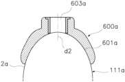
그리고, 도 10을 참조하면, 상기 가상 서지컬 가이드(600a)에 대응되는 실물의 상기 서지컬 가이드(600)가 상기 제조장치(930)를 통해 제조될 수 있다. 여기서, 상기 제조장치(930)에 의해 상기 서지컬 가이드(600)에 상기 가상 고정홈부(601a)에 대응되는 상기 고정홈부(601)가 형성되며, 상기 가상 정렬홈부(602a)에 대응되는 상기 정렬홈부(602)가 형성되고, 상기 가상 가이드홀(603a)에 대응되는 상기 가이드홀(603)이 형성될 수 있다. 예컨대, 상기 서지컬 가이드(600)에 상기 가상 구치측 정렬홈부에 대응되는 한쌍의 구치측 정렬홈부가 형성되고, 상기 가상 전치측 정렬홈부에 대응되는 전치측 정렬홈부가 형성될 수 있다.And, referring to FIG. 10, the actual surgical guide (600) corresponding to the virtual surgical guide (600a) can be manufactured through the manufacturing device (930). Here, the fixing groove (601) corresponding to the virtual fixing groove (601a) can be formed in the surgical guide (600) by the manufacturing device (930), the alignment groove (602) corresponding to the virtual alignment groove (602a) can be formed, and the guide hole (603) corresponding to the virtual guide hole (603a) can be formed. For example, a pair of molar-side alignment grooves corresponding to the virtual molar-side alignment grooves can be formed in the surgical guide (600), and an anterior-side alignment groove corresponding to the virtual anterior-side alignment grooves can be formed.
여기서, 상기 서지컬 가이드(600)는 피시술자의 구강 내부 형상 및 상기 걸림고정용 헤드부(820)에 형합되는 상기 고정홈부(601) 및 상기 정렬홈부(602)를 포함하여 제조된다. 또한, 상기 서지컬 가이드(600)는 상기 픽스츄어(f)의 식립위치 및 방향(d1)을 따라 상기 가이드홀(603)이 관통되도록 제조된다. 이때, 상기 서지컬 가이드(600)는 상기 고정홈부(601) 및 상기 정렬홈부(602)가 상기 식립대상부(2) 및 상기 걸림고정용 헤드부(820)에 각각 형합되어 고정된다. 이에 따라, 상기 서지컬 가이드(600)가 상기 식립대상부(2) 및 상기 걸림고정용 헤드부(820)에 고정된 상태에서, 상기 가이드홀(603)을 통해 상기 픽스츄어(f)의 식립을 위한 천공이 드릴링될 수 있다.Here, the surgical guide (600) is manufactured including the fixing groove (601) and the alignment groove (602) that are conformed to the internal shape of the oral cavity of the subject and the hooking and fixing head (820). In addition, the surgical guide (600) is manufactured so that the guide hole (603) passes through along the implantation position and direction (d1) of the fixture (f). At this time, the surgical guide (600) is fixed by conforming the fixing groove (601) and the alignment groove (602) to the implantation target portion (2) and the hooking and fixing head portion (820), respectively. Accordingly, while the surgical guide (600) is fixed to the implantation target portion (2) and the fixing head portion (820), a hole for implantation of the fixture (f) can be drilled through the guide hole (603).
이러한 서지컬 가이드(600)는 상기 고정홈부(601)가 상기 식립대상부(2)의 외면과 실질적으로 형합되도록 상기 식립측 스캐닝이미지(111a)에 포함된 상기 식립대상부의 외면 윤곽을 기반으로 설정된다. 즉, 상기 고정홈부(601)의 내면 윤곽이 상기 식립대상부의 외면 윤곽과 실질적으로 형합되도록 설정됨에 따라 상기 서지컬 가이드(600)가 피시술자의 구강 내부에 설치된 상태에서 드릴링 및 식립작업이 정확한 위치에 수행될 수 있다.This surgical guide (600) is set based on the outer surface outline of the implantation target portion (2) included in the implantation-side scanning image (111a) so that the fixing groove portion (601) substantially conforms to the outer surface of the implantation target portion. That is, since the inner surface outline of the fixing groove portion (601) is set to substantially conform to the outer surface outline of the implantation target portion, drilling and implantation work can be performed at an accurate position while the surgical guide (600) is installed inside the oral cavity of the recipient.
더욱이, 상기 정렬홈부(602)가 상기 가이드픽싱스크류(800)의 걸림고정용 헤드부(820)의 외면과 실질적으로 형합되도록 상기 헤드부 스캐닝이미지(15a) 및 상기 헤드부 CT 이미지(25a)가 중첩 정합되어 생성된 상기 헤드부 중첩정합이미지를 기반으로 설정된다. 즉, 상기 정렬홈부(602)의 내면 윤곽이 상기 걸림고정용 헤드부(820)의 외면 윤곽과 실질적으로 형합되도록 설정된다. 이에 따라, 상기 정렬홈부(602)가 상기 걸림고정용 헤드부(820)에 걸림고정되며 결합되어 상기 서지컬 가이드(600)가 잇몸 높이가 낮은 무치악 피시술자의 구강 내부에 설치된 상태에서 드릴링 및 식립작업시 유동을 방지하며 지지력을 제공할 수 있다. 따라서, 상기 서지컬가이드(600)의 상기 정렬홈부(602)의 내면 윤곽이 상기 걸림고정용 헤드부(820)의 외면 윤곽과 형합 대응되어 설계 및 제조되어 피시술자의 구강 내부에 식립된 상기 가이드픽싱스크류(800)의 걸림고정용 헤드부(820)에 정렬되며 걸림고정되어 결합될 수 있다. 이를 통해, 잇몸 리지가 낮은 무치악 식립대상부의 드릴링 및 식립작업시에도 유동을 방지하며 안정적인 고정 지지력을 제공할 수 있다.Furthermore, the alignment groove (602) is set based on the head superimposed alignment image generated by overlapping and matching the head scanning image (15a) and the head CT image (25a) so that the outer surface of the engaging and fixing head (820) of the guide fixing screw (800) is substantially aligned. That is, the inner contour of the alignment groove (602) is set so as to substantially match the outer surface contour of the engaging and fixing head (820). Accordingly, the alignment groove (602) is engaged and fixed to the engaging and fixing head (820), so that the surgical guide (600) can prevent movement and provide support during drilling and implantation work in a state where it is installed in the oral cavity of an edentulous patient with a low gum height. Accordingly, the inner contour of the alignment groove (602) of the surgical guide (600) is designed and manufactured to correspond to the outer contour of the engaging and fixing head (820), so that it can be aligned with the engaging and fixing head (820) of the guide fixing screw (800) implanted inside the oral cavity of the recipient and connected thereto. Through this, even when drilling and implanting an edentulous implantation site with a low gum ridge, movement can be prevented and a stable fixing support force can be provided.
그리고, 상기 고정홈부(601)가 설계되면, 상기 서지컬 가이드(600)가 상기 식립대상부에 고정된 상태에서 상기 픽스츄어(f)의 식립위치 및 방향(d1)과 평행하도록 상기 가이드홀(603)의 관통방향(d2)을 설정하여 제조할 수 있다. 이에 따라, 상기 서지컬 가이드(600)에 의해 가이드되어 드릴링된 천공의 위치 및 방향과 이에 식립되는 상기 식립물의 위치 및 방향이 기수립된 임플란트 식립계획에 대응하여 정확하게 가이드될 수 있다.And, when the above-mentioned fixed groove part (601) is designed, the surgical guide (600) can be manufactured by setting the penetration direction (d2) of the guide hole (603) to be parallel to the implantation position and direction (d1) of the fixture (f) while being fixed to the implantation target part. Accordingly, the position and direction of the drilled hole guided by the surgical guide (600) and the position and direction of the implanted object to be implanted can be accurately guided in response to the established implantation plan.
또한, 별도의 인상채득 과정 없이도 피시술자의 구강 내부에 대하여 획득된 각 이미지로부터 상기 식립물 및 상기 서지컬 가이드에 대한 설계정보를 제공받을 수 있다. 이를 통해, 임플란트 식립계획부터 식립작업까지 단기간에 진행되면서도 정밀성이 향상된 임플란트 식립이 수행되므로 피시술자의 식립만족감이 현저히 향상될 수 있다.In addition, design information for the implant and the surgical guide can be provided from each image acquired of the inside of the oral cavity of the recipient without a separate impression acquisition process. Through this, implant placement can be performed with improved precision while proceeding in a short period of time from the implant placement plan to the implantation operation, so that the recipient's satisfaction with the implantation can be significantly improved.
한편, 상기 3차원 플래닝이미지(116)를 기반으로 상기 정렬홈부(602)에 대응되는 임시걸림홈부(702)가 형성된 임시보철(700)이 상기 플래닝부(920)에 의해 설계되고 상기 제조장치(930)를 이용하여 제조된다(s40). 이때, 상기 임시보철(700)은 최종적으로 제조되는 최종보철과 같은 치아수복물의 제조전에 피시술자의 구강 내부에 설치되어 임시로 사용되는 치아수복물을 의미한다.Meanwhile, a temporary prosthesis (700) having a temporary catch groove (702) corresponding to the alignment groove (602) formed based on the three-dimensional planning image (116) is designed by the planning unit (920) and manufactured using the manufacturing device (930) (s40). At this time, the temporary prosthesis (700) refers to a dental restoration that is temporarily installed inside the oral cavity of the recipient before the manufacturing of the final prosthesis, such as the dental restoration that is finally manufactured.
여기서, 도 6 및 도 11 및 도 12를 참조하면, 상기 3차원 플래닝이미지(116)를 기반으로 상기 식립대상부(2)의 치열라인에 대응되어 라운드지게 연장되되 상기 식립대상부(2)에 형합되도록 일면을 따라 임시형합홈부(701)가 함몰 형성되며 상기 걸림고정용 헤드부(820)에 형합되도록 상기 임시형합홈부(701)의 적어도 어느 일측으로부터 상기 임시걸림홈부(702)가 함몰 형성되고 상기 수직고경(VD)에 대응되어 임시교합홈부(703)가 형성되는 상기 임시보철(700)이 상기 플래닝부(920)에 의해 설계되고 상기 제조장치(930)를 이용하여 제조될 수 있다. 이때, 상기 임시형합홈부(701) 및 상기 임시교합홈부(703) 사이 간격이 상기 수직고경(VD)에 대응되어 설정되어 제조될 수 있다.Here, referring to FIG. 6 and FIG. 11 and FIG. 12, based on the three-dimensional planning image (116), a temporary shaping groove (701) is formed by being sunken along one side to correspond to the tooth line of the implantation target portion (2) and to be fitted with the implantation target portion (2), and a temporary engaging groove (702) is formed by being sunken from at least one side of the temporary shaping groove (701) to be fitted with the engaging and fixing head portion (820), and a temporary occlusal groove (703) is formed to correspond to the vertical dimension (VD), and the temporary prosthesis (700) can be designed by the planning unit (920) and manufactured using the manufacturing device (930). At this time, the interval between the temporary shaping groove (701) and the temporary occlusal groove (703) can be set to correspond to the vertical dimension (VD) and manufactured.
상세히, 상기 임시보철(700)의 설계과정을 설명하면, 먼저 상기 식립대상부(2)의 치열라인에 대응되어 라운드지게 연장되는 가상 임시보철(700a)이 상기 플래닝부(920)에 의해 생성될 수 있다.In detail, the design process of the temporary prosthesis (700) will be described. First, a virtual temporary prosthesis (700a) that is extended in a round shape corresponding to the tooth line of the implantation target portion (2) can be created by the planning portion (920).
이때, 상기 가상 임시보철(700a)에는 상기 식립대상부(2)에 형합 대응되는 가상 임시형합홈부(701a)가 상기 플래닝부(920)에 의해 생성될 수 있다. 그리고, 상기 가상 임시보철(700a)에는 상기 3차원 플래닝이미지(116)에서 상기 걸림고정용 헤드부(820)의 위치에 대응되는 상기 임시형합홈부(701)의 적어도 어느 일측으로부터 상기 걸림고정용 헤드부(820)에 형합 대응되는 적어도 하나 이상의 가상 임시걸림홈부(702a)가 상기 플래닝부(920)에 의해 생성될 수 있다. 즉, 상기 가상 임시걸림홈부(702a)는 상기 헤드부 스캐닝이미지(15a) 및 상기 헤드부 CT 이미지(25a)가 중첩 정합되어 생성된 상기 헤드부 중첩정합이미지의 위치에 대응되는 상기 임시형합홈부(701)의 적어도 어느 일측에 생성될 수 있다. 예컨대, 상기 식립대상부(2)의 각 구치측으로부터 돌출된 상기 걸림고정용 헤드부(820)에 형합 대응되는 한쌍의 가상 구치측 정렬홈부가 생성되며, 상기 식립대상부(2)의 전치측으로부터 돌출된 상기 걸림고정용 헤드부(820)에 형합 대응되는 가상 전치측 정렬홈부가 생성될 수 있다. 여기서, 상기 가상 임시걸림홈부(702a)는 상기 걸림고정용 헤드부(820)에 형합 대응되는 상기 가상 정렬홈부(602a) 대응되는 형상으로 설정됨이 바람직하다. 또한, 상기 임시걸림홈부(702)는 상기 정렬홈부(602)에 대응되는 형상으로 형성됨이 바람직하다.At this time, in the virtual temporary prosthesis (700a), a virtual temporary shaping groove (701a) corresponding to the implantation target portion (2) may be created by the planning unit (920). In addition, in the virtual temporary prosthesis (700a), at least one virtual temporary engaging groove (702a) corresponding to the engaging and fixing head portion (820) from at least one side of the temporary shaping groove (701) corresponding to the position of the engaging and fixing head portion (820) in the three-dimensional planning image (116) may be created by the planning unit (920). That is, the virtual temporary engaging groove (702a) can be created on at least one side of the temporary aligning groove (701) corresponding to the position of the head overlapping aligned image generated by overlapping and aligning the head scanning image (15a) and the head CT image (25a). For example, a pair of virtual molar-side alignment grooves can be created corresponding to the engaging and fixing head parts (820) protruding from each molar side of the implantation target part (2), and a virtual anterior-side alignment groove can be created corresponding to the engaging and fixing head parts (820) protruding from the anterior side of the implantation target part (2). Here, it is preferable that the virtual temporary engaging groove (702a) be set to a shape corresponding to the virtual alignment groove (602a) corresponding to the engaging and fixing head parts (820). In addition, it is preferable that the temporary holding groove (702) be formed in a shape corresponding to the alignment groove (602).
그리고, 상기 가상 임시보철(700a)에는 상기 가상 임시형합홈부(701a) 및 상기 가상 임시교합홈부(703a) 사이 간격이 상기 수직고경(VD)에 대응되어 설정될 수 있다. 또한, 상기 3차원 플래닝이미지(116)를 기반으로 높이가 설정된 상기 크라운(c)에 대응되어 상기 가상 임시보철(700a)의 가상 임시치아부가 설계되며 상기 가상 임시치아부의 단부가 상기 가상 임시교합홈부(703a)로서 설정될 수 있다. 여기서, 상기 가상 임시보철(700a), 상기 가상 임시형합홈부(701a), 상기 가상 임시걸림홈부(702a) 및 상기 가상 임시교합홈부(703a)는 상기 플래닝부(920)에 의해 생성되는 가상의 3차원 이미지데이터로서 이해함이 바람직하다.And, in the virtual temporary prosthesis (700a), the gap between the virtual temporary shaping groove (701a) and the virtual temporary occlusal groove (703a) can be set to correspond to the vertical diameter (VD). In addition, the virtual temporary tooth part of the virtual temporary prosthesis (700a) is designed to correspond to the crown (c) whose height is set based on the three-dimensional planning image (116), and an end of the virtual temporary tooth part can be set as the virtual temporary occlusal groove (703a). Here, it is preferable to understand that the virtual temporary prosthesis (700a), the virtual temporary shaping groove (701a), the virtual temporary engaging groove (702a), and the virtual temporary occlusal groove (703a) are virtual three-dimensional image data generated by the planning part (920).
더욱이, 경우에 따라 상기 가상 임시보철(700a)에는 상기 가상 임시걸림홈부(702a)에 이격되되 상기 픽스츄어의 식립 위치(도 4b의 6)에 대응되는 위치에 상기 픽스츄어(f) 및 상기 어버트먼트(a)의 식립을 위한 가상 천공홀(미도시)이 상기 플래닝부(920)에 의해 생성될 수도 있다.Furthermore, in some cases, a virtual drilling hole (not shown) for implanting the fixture (f) and the abutment (a) may be created by the planning unit (920) at a position corresponding to the implantation position of the fixture (6 in FIG. 4b) but spaced apart from the virtual temporary catch groove (702a) in the virtual temporary prosthesis (700a).
그리고, 상기 가상 임시보철(700a)에 대응되는 실물의 상기 임시보철(700)이 상기 제조장치(930)를 통해 제조될 수 있다. 여기서, 상기 제조장치(930)에 의해 상기 임시보철(700)에 상기 가상 임시형합홈부(701a)에 대응되는 상기 임시형합홈부(701)가 형성되며, 적어도 하나 이상의 상기 가상 임시걸림홈부(702a)에 대응되는 적어도 하나 이상의 상기 임시걸림홈부(702)가 형성되고, 상기 가상 임시교합홈부(703a)에 대응되는 상기 임시교합홈부(703)이 형성될 수 있으며, 상기 가상 임시치아부에 대응되는 임시치아부가 형성될 수 있다. 예컨대, 상기 임시보철(700)에 상기 가상 구치측 임시걸림홈부에 대응되는 한쌍의 구치측 임시걸림홈부가 형성되고, 상기 가상 전치측 임시걸림홈부에 대응되는 전치측 임시걸림홈부가 형성될 수 있다.And, the actual temporary prosthesis (700) corresponding to the virtual temporary prosthesis (700a) can be manufactured through the manufacturing device (930). Here, the temporary shaping groove (701) corresponding to the virtual temporary shaping groove (701a) is formed in the temporary prosthesis (700) by the manufacturing device (930), at least one temporary catching groove (702) corresponding to at least one virtual temporary engaging groove (702a) is formed, the temporary catching groove (703) corresponding to the virtual temporary occlusal groove (703a) can be formed, and the temporary tooth portion corresponding to the virtual temporary tooth portion can be formed. For example, a pair of temporary engaging grooves on the molar side corresponding to the virtual temporary engaging grooves on the molar side may be formed on the temporary prosthesis (700), and a temporary engaging groove on the anterior side corresponding to the virtual temporary engaging groove on the anterior side may be formed.
여기서, 상기 임시보철(700)은 피시술자의 구강 내부 형상 및 상기 걸림고정용 헤드부(820)에 형합되는 상기 임시형합홈부(701) 및 상기 임시걸림홈부(702)를 포함하여 제조된다. 또한, 경우에 따라 상기 임시보철(700)은 상기 픽스츄어(f)의 식립위치 및 방향(d1)을 따라 상기 가상 천공홀(미도시)에 대응되는 천공홀(미도시)이 관통되도록 제조될 수도 있다. 이때, 상기 임시보철(700)은 상기 임시형합홈부(701) 및 상기 임시걸림홈부(702)가 상기 식립대상부(2) 및 상기 걸림고정용 헤드부(820)에 각각 형합되어 고정된 상태에서 사용될 수 있다.Here, the temporary prosthesis (700) is manufactured including the temporary shaping groove (701) and the temporary catching groove (702) that are conformed to the internal shape of the oral cavity of the subject and the engaging and fixing head (820). In addition, in some cases, the temporary prosthesis (700) may be manufactured so that a perforation hole (not shown) corresponding to the virtual perforation hole (not shown) passes through along the implantation position and direction (d1) of the fixture (f). At this time, the temporary prosthesis (700) can be used in a state where the temporary shaping groove (701) and the temporary catching groove (702) are respectively conformed and fixed to the implantation target portion (2) and the engaging and fixing head (820).
더욱이, 상기 임시걸림홈부(702)가 상기 가이드픽싱스크류(800)의 걸림고정용 헤드부(820)의 외면과 실질적으로 형합되도록 상기 헤드부 스캐닝이미지(15a) 및 상기 헤드부 CT 이미지(25a)가 중첩 정합되어 생성된 상기 헤드부 중첩정합이미지를 기반으로 설정된다. 즉, 상기 임시걸림홈부(702)의 내면 윤곽이 상기 걸림고정용 헤드부(820)의 외면 윤곽과 실질적으로 형합되도록 설정된다. 이에 따라, 상기 임시걸림홈부(702)가 상기 걸림고정용 헤드부(820)에 걸림고정되며 결합되어 상기 임시보철(700)이 잇몸 높이가 낮은 무치악 피시술자의 구강 내부에 설치된 상태에서 유동을 방지하며 안정적으로 고정된 상태로 사용될 수 있다. 따라서, 상기 임시걸림홈부(702)의 내면 윤곽이 상기 걸림고정용 헤드부(820)의 외면 윤곽과 형합 대응되어 설계 및 제조되어 피시술자의 구강 내부에 식립된 상기 가이드픽싱스크류(800)의 걸림고정용 헤드부(820)에 정렬되며 걸림고정되어 결합될 수 있다. 이를 통해, 잇몸 리지가 낮은 무치악 식립대상부에 상기 임시보철(700)이 설치시에도 유동을 방지하며 안정적인 고정 지지력을 제공할 수 있다.Furthermore, the temporary engaging groove (702) is set based on the head overlapping matching image generated by overlapping and matching the head scanning image (15a) and the head CT image (25a) so that the outer surface of the engaging and fixing head (820) of the guide fixing screw (800) is substantially aligned. That is, the inner contour of the temporary engaging groove (702) is set so that the outer surface contour of the engaging and fixing head (820) is substantially aligned. Accordingly, the temporary engaging groove (702) is engaged and fixed to the engaging and fixing head (820), so that the temporary prosthesis (700) can be used while preventing movement and stably fixed in a state where it is installed in the oral cavity of an edentulous patient with a low gum height. Accordingly, the inner contour of the temporary retaining groove (702) is designed and manufactured to correspond to the outer contour of the retaining head (820) so that it can be aligned with the retaining head (820) of the guide fixing screw (800) implanted inside the oral cavity of the patient and be engaged by being retained. Through this, even when the temporary prosthesis (700) is installed in an edentulous implantation site with a low gum ridge, it can prevent movement and provide stable fixing support.
한편, 도 13 내지 도 14를 참조하면, 본 발명의 일실시예에 따른 가이드픽싱스크류(800)는 상기 나사부(810) 및 상기 걸림고정용 헤드부(820)를 포함한다.Meanwhile, referring to FIGS. 13 and 14, a guide fixing screw (800) according to one embodiment of the present invention includes the screw portion (810) and the head portion (820) for fixing the catch.
여기서, 상기 나사부(810)는 상기 식립대상부(도 4a의 2)에 셀프 탭핑되도록 길이방향을 따라 연장되며 외주에 상기 체결나사산(811)이 형성됨이 바람직하다.Here, it is preferable that the screw portion (810) extends along the longitudinal direction so as to self-tap on the implantation target portion (2 of FIG. 4a) and that the fastening screw thread (811) is formed on the outer periphery.
그리고, 상기 나사부(810)에는 일단부 반경방향 중심으로부터 길이방향 외측으로 첨단부(812)가 일체로 돌출 형성됨이 바람직하다. 이때, 상기 첨단부(812)는 상기 식립대상부(도 4a의 2)를 가압하며 셀프 탭핑되도록 상기 체결나사산(811)의 직경 미만으로 설정되되 첨예한 형상으로 단부가 형성될 수 있다.In addition, it is preferable that the screw portion (810) be formed with a tip (812) that protrudes integrally from the center in the radial direction toward the outer side in the longitudinal direction. At this time, the tip (812) may be set to be smaller than the diameter of the fastening screw thread (811) so as to pressurize the implantation target portion (2 of FIG. 4a) and self-tap, but the end may be formed with a sharp shape.
더욱이, 상기 나사부(810)에는 하부 일측에 절삭면(813)이 함몰 형성될 수 있다. 이때, 상기 절삭면(813)은 상기 첨단부(812)에 인접한 상기 체결나사산(811)의 단부 일측에 형성될 수 있으며, 상기 체결나사산(811)의 단부가 상기 절삭면(813)에 의해 절삭된 형태로 형성될 수 있다.Furthermore, a cutting surface (813) may be formed recessed on the lower side of the screw portion (810). At this time, the cutting surface (813) may be formed on one side of the end of the fastening screw thread (811) adjacent to the tip portion (812), and the end of the fastening screw thread (811) may be formed in a form cut by the cutting surface (813).
또한, 상기 나사부(810)는 일단부로 갈수록 원주방향을 따라 반경방향 내측으로 연속적으로 테이퍼지게 협소화됨이 바람직하다. 즉, 상기 나사부(810)는 상기 헤드부(820)에서 상기 첨단부(812)로 갈수록 직경이 협소화되는 형태로 형성됨이 바람직하다.In addition, it is preferable that the screw portion (810) is continuously tapered inwardly in the radial direction as it goes toward one end. That is, it is preferable that the screw portion (810) is formed in a form in which the diameter becomes narrower as it goes from the head portion (820) to the tip portion (812).
한편, 상기 걸림고정용 헤드부(820)는 상기 나사부(810)의 타단부에 원주방향을 따라 반경방향 외측으로 절곡지게 확장 형성되며, 표면에 상기 수직측면부(821), 상기 평탄면부(822) 및 상기 라운드면부(823)이 연속적으로 형성됨이 바람직하다. 또한, 상기 걸림고정용 헤드부(820)의 표면은 샌드블라스트 처리되어 높은 마찰력을 갖도록 형성될 수 있다.Meanwhile, the head portion (820) for fixing the hook is formed to extend radially outwardly along the circumferential direction at the other end of the screw portion (810), and it is preferable that the vertical side portion (821), the flat surface portion (822), and the round surface portion (823) are formed continuously on the surface. In addition, the surface of the head portion (820) for fixing the hook can be formed to have high friction by being sandblasted.
상세히, 상기 걸림고정용 헤드부(820)는 상기 나사부(810)의 타단부에 원주방향을 따라 반경방향 외측으로 절곡지게 확장된 외측단으로부터 상기 나사부(810)의 길이방향을 따라 형성되는 상기 수직측면부(821)를 포함함이 바람직하다.In detail, it is preferable that the head portion (820) for fixing the above-mentioned screw portion includes the vertical side portion (821) formed along the longitudinal direction of the screw portion (810) from an outer end that is bent radially outwardly along the circumferential direction at the other end of the screw portion (810).
그리고, 상기 걸림고정용 헤드부(820)는 단부에 형성되되 중앙부로부터 상기 나사부(810)를 향하여 상기 체결홈(824)이 함몰 형성되는 상기 평탄면부(822)를 포함함이 바람직하다. 이때, 상기 평탄면부(822)는 상기 나사부(810)의 길이방향에 수직인 평탄면으로서 형성됨이 바람직하다. 더불어, 상기 체결홈(824)는 상기 평탄면부(822)의 반경방향 중앙으로부터 상기 나사부(810)측으로 함몰 형성됨이 바람직하다.And, it is preferable that the head portion (820) for fixing the hook is formed at an end portion and includes a flat surface portion (822) in which the fastening groove (824) is formed recessed from the center portion toward the screw portion (810). At this time, it is preferable that the flat surface portion (822) is formed as a flat surface perpendicular to the longitudinal direction of the screw portion (810). In addition, it is preferable that the fastening groove (824) is formed recessed from the radial center of the flat surface portion (822) toward the screw portion (810).
이때, 상기 체결홈(824)은 상기 나사부(810)가 상기 식립대상부(도 4a의 2)에 셀프 탭핑되도록 회전시 회전체결장치(미도시)가 체결된 상태에서 회전되도록 내벽면이 다각 단면 형상으로 형성될 수 있다.At this time, the inner wall surface of the fastening groove (824) can be formed into a polygonal cross-section shape so that the screw portion (810) rotates while the rotating fastening device (not shown) is fastened so that it self-tap on the implantation target portion (2 of FIG. 4a).
또한, 상기 걸림고정용 헤드부(820)는 상기 수직측면부(821) 및 상기 평탄면부(822) 사이에 테두리를 따라 라운드진 외면 윤곽으로 형성되는 상기 라운드면부(923)를 포함함이 바람직하다.In addition, it is preferable that the head portion (820) for fixing the hook include the round surface portion (923) formed with a rounded outer surface outline along the edge between the vertical side portion (821) and the flat surface portion (822).
여기서, 상기 정렬홈부(602) 및 상기 임시걸림홈부(702)의 윤곽이 상기 걸림고정용 헤드부(820)의 표면 윤곽에 대응되어 형성됨이 바람직하다. 그리고, 상기 나사부(810)가 상기 식립대상부(도 4a의 2)에 식립되어 고정된 상태에서, 각 상기 정렬홈부(602) 또는 각 상기 임시걸림홈부(702)가 각 상기 걸림고정용 헤드부(820)에 각각 걸림 결합될 수 있다. 즉, 상기 서지컬 가이드(600)에 형성된 적어도 하나 이상의 상기 정렬홈부(602)가 상기 걸림고정용 헤드부(820)에 걸림 결합되되, 상기 정렬홈부(602)가 상기 서지컬 가이드(600)에 복수개 형성된 경우 각 상기 걸림고정용 헤드부(820)에 동시에 걸림 결합될 수 있다. 또한, 즉, 상기 임시보철(700)에 형성된 적어도 하나 이상의 상기 임시걸림홈부(702)가 상기 걸림고정용 헤드부(820)에 걸림 결합되되, 상기 임시걸림홈부(702)가 상기 임시보철(700)에 복수개 형성된 경우 각 상기 걸림고정용 헤드부(820)에 동시에 걸림 결합될 수 있다.Here, it is preferable that the outlines of the alignment groove (602) and the temporary engaging groove (702) are formed to correspond to the surface outline of the engaging and fixing head (820). In addition, when the screw portion (810) is implanted and fixed in the implantation target portion (2 of FIG. 4A), each of the alignment grooves (602) or each of the temporary engaging grooves (702) can be engaged and fixed to each of the engaging and fixing head portions (820). That is, at least one of the alignment grooves (602) formed on the surgical guide (600) is engaged and fixed to the engaging and fixing head portion (820), and when a plurality of the alignment grooves (602) are formed on the surgical guide (600), they can be engaged and fixed to each of the engaging and fixing head portions (820) at the same time. In addition, that is, at least one temporary engaging groove (702) formed on the temporary prosthesis (700) is engaged with the engaging and fixing head portion (820), and when a plurality of temporary engaging grooves (702) are formed on the temporary prosthesis (700), they can be engaged with each engaging and fixing head portion (820) at the same time.
이때, 상기 걸림고정용 헤드부(820)에 테두리를 따라 라운드진 외면 윤곽으로 상기 라운드면부(923)가 형성됨에 따라 각 상기 정렬홈부(602) 또는 각 상기 임시걸림홈부(702)가 각 상기 걸림고정용 헤드부(820)에 용이하게 삽입되어 걸림 결합될 수 있다. 또한, 상기 나사부(810)의 타단부에 원주방향을 따라 반경방향 외측으로 절곡지게 확장된 외측단으로부터 상기 나사부(810)의 길이방향을 따라 형성된 상기 수직측면부(821)에 각 상기 정렬홈부(602) 또는 각 상기 임시걸림홈부(702)가 형합될 수 있다.At this time, since the round surface portion (923) is formed with a rounded outer surface outline along the edge of the fixing head portion (820), each of the alignment groove portions (602) or each of the temporary fixing groove portions (702) can be easily inserted into each of the fixing head portions (820) and fixedly connected. In addition, each of the alignment groove portions (602) or each of the temporary fixing groove portions (702) can be fitted into the vertical side portion (821) formed along the longitudinal direction of the screw portion (810) from the outer end that is extended radially outwardly along the circumferential direction of the other end of the screw portion (810).
이를 통해, 치아수복물로서 제조된 상기 서지컬 가이드(600)의 정렬홈부(602) 또는 상기 임시보철(700)의 임시걸림홈부(702)가 상기 걸림고정용 헤드부(820)에 라운드진 외면 윤곽으로 형성된 상기 라운드면부(823)에 용이하게 안내 및 삽입된 후 상기 수직측면부(821)에 형합되므로 치아수복물의 설치편의성이 현저히 개선될 수 있다.Through this, the alignment groove (602) of the surgical guide (600) manufactured as a dental restoration or the temporary engaging groove (702) of the temporary prosthesis (700) can be easily guided and inserted into the round surface (823) formed with a rounded outer contour of the engaging fixing head (820) and then fitted into the vertical side surface (821), so that the convenience of installing the dental restoration can be significantly improved.
또한, 치아수복물로서 제조된 상기 서지컬 가이드(600)의 정렬홈부(602) 또는 상기 임시보철(700)의 임시걸림홈부(702)가 상기 걸림고정용 헤드부(820)의 상기 수직측면부(821)에 형합되어 설치 후 진동 및 분리가 방지되므로 잇몸 리지가 낮은 무치악 환자의 구강에 식립된 상기 가이드픽싱스크류(800)에 설치되는 치아수복물의 위치가 정밀하게 유지되어 정확한 시술을 보장할 수 있다.In addition, the alignment groove (602) of the surgical guide (600) manufactured as a dental restoration or the temporary engaging groove (702) of the temporary prosthesis (700) is fitted into the vertical side surface (821) of the engaging fixing head (820) to prevent vibration and separation after installation, so that the position of the dental restoration installed on the guide fixing screw (800) implanted in the oral cavity of an edentulous patient with a low gum ridge is precisely maintained, thereby ensuring accurate treatment.
이때, 이상에서 기재된 "포함하다", "구성하다" 또는 "구비하다" 등의 용어는, 특별히 반대되는 기재가 없는 한, 해당 구성 요소가 내재할 수 있음을 의미하는 것이므로, 다른 구성 요소를 제외하는 것이 아니라 다른 구성 요소를 더 포함할 수 있는 것으로 해석되어야 한다. 기술적이거나 과학적인 용어를 포함한 모든 용어들은, 다르게 정의되지 않는 한, 본 발명이 속하는 기술 분야에서 통상의 지식을 가진 자에 의해 일반적으로 이해되는 것과 동일한 의미가 있다. 사전에 정의된 용어와 같이 일반적으로 사용되는 용어들은 관련 기술의 문맥상의 의미와 일치하는 것으로 해석되어야 하며, 본 발명에서 명백하게 정의하지 않는 한, 이상적이거나 과도하게 형식적인 의미로 해석되지 않는다.Here, the terms "include," "compose," or "have," etc. described above, unless otherwise specifically stated, mean that the corresponding component may be present, and therefore should be interpreted as including other components rather than excluding other components. All terms, including technical or scientific terms, unless otherwise defined, have the same meaning as generally understood by a person of ordinary skill in the art to which the present invention pertains. Commonly used terms, such as terms defined in a dictionary, should be interpreted as being consistent with the contextual meaning of the relevant technology, and shall not be interpreted in an ideal or overly formal meaning unless explicitly defined in the present invention.
이상 설명한 바와 같이, 본 발명은 상술한 각 실시예에 한정되는 것은 아니며, 본 발명의 청구항에서 청구하는 범위를 벗어남 없이 본 발명이 속하는 기술분야에서 통상의 지식을 가진 자에 의해 변형 실시되는 것은 가능하며, 이러한 변형 실시는 본 발명의 범위에 속한다.As described above, the present invention is not limited to each of the embodiments described above, and modifications may be made by a person skilled in the art without departing from the scope claimed in the claims of the present invention, and such modifications fall within the scope of the present invention.
1 : 구강 내부2 : 식립대상부
3 : 대합대상부5: 가이드픽싱스크류
5a: 걸림고정용 헤드부111 : 스캐닝이미지
114 : CT 이미지116 : 3차원 교합 가이드 이미지
600 : 서지컬 가이드600a: 가상 서지컬 가이드
601 : 고정홈부601a: 가상 고정홈부
602 : 정렬홈부602a: 가상 정렬홈부
603: 가이드홀603a: 가상 가이드홀
700: 임시보철700a: 가상 임시보철
701: 임시형합홈부701a: 가상 임시형합홈부
702: 임시걸림홈부702a: 가상 임시걸림홈부
703: 임시교합홈부703a: 가상 임시교합홈부
800: 가이드픽싱스크류810: 나사부
811: 체결나사산812: 첨단부
813: 절삭면820: 걸림고정용 헤드부
824: 체결홈901: 촬상장치
902: 플래닝부903: 제조장치1: Inside the mouth 2: Target area for implantation
3: Conveyor belt 5: Guide fixing screw
5a: Head for fixing the hook 111: Scanning image
114: CT image 116: 3D occlusion guide image
600:
601: Fixed home
602:
603:
700:
701:
702:
703: Temporary
800: Guide fixing screw 810: Screw part
811: Fastening screw thread 812: Tip
813: Cutting surface 820: Head part for fixing
824: Fastening groove 901: Image capture device
902: Planning Department 903: Manufacturing Equipment
Claims (5)
Translated fromKorean상기 스캐닝이미지 및 상기 CT 이미지에 표시된 공통부분을 기준으로 중첩 및 정합되어 교합높이가 고려된 3차원 플래닝이미지가 상기 플래닝부에 의해 생성되는 제2단계;
상기 3차원 플래닝이미지를 기반으로 상기 식립대상부의 치열라인에 대응되어 라운드지게 연장되되 상기 식립대상부에 형합되도록 일면을 따라 고정홈부가 함몰 형성되며 상기 헤드부에 형합되도록 상기 고정홈부의 적어도 어느 일측으로부터 정렬홈부가 함몰 형성되고 상기 가이드픽싱스크류와 이격 배치되는 픽스츄어의 식립 위치에 대응되어 가이드홀이 관통 형성된 서지컬 가이드가 상기 플래닝부에 의해 설계되고 제조장치를 이용하여 제조되는 제3단계; 및
상기 3차원 플래닝이미지를 기반으로 상기 정렬홈부에 대응되는 임시걸림홈부가 형성된 임시보철이 상기 플래닝부에 의해 설계되고 상기 제조장치를 이용하여 제조되는 제4단계를 포함하되,
상기 제3단계는, 상기 식립대상부의 치열라인에 대응되어 라운드지게 연장되는 가상 서지컬 가이드가 생성되는 단계와,
상기 가상 서지컬 가이드에 상기 식립대상부에 형합 대응되는 가상 고정홈부가 생성되고, 상기 헤드부의 위치에 대응되도록 상기 가상 고정홈부의 적어도 어느 일측으로부터 상기 수직측면부에 형합 대응되는 가상 정렬홈부가 생성되는 단계와,
상기 가상 서지컬 가이드에 상기 픽스츄어의 식립 위치에 대응되어 가상 가이드홀이 상기 가상 정렬홈부에 이격되며 생성되는 단계와,
상기 서지컬 가이드에 상기 가상 고정홈부에 대응되는 상기 고정홈부가 형성되며, 상기 가상 정렬홈부에 대응되는 상기 정렬홈부가 형성되고, 상기 가상 가이드홀에 대응되는 상기 가이드홀이 형성되는 단계를 포함함을 특징으로 하는 가이드픽싱스크류를 이용한 치아수복물 제조방법.A first step in which at least one guide fixing screw is formed, wherein a plurality of scanning images of an edentulous implantation target area and an opposing target area are acquired through an imaging device and a CT image of the oral cavity is transmitted to a planning section, wherein a head portion for engaging and fixing is formed, wherein a vertical side portion formed in a longitudinal direction from an outer end expanded radially outwardly along a circumferential direction at an end of a screw portion on which a fastening screw thread is formed and a rounded surface portion formed between a flat surface portion in which a fastening groove is sunken in is formed, are formed;
A second step in which a three-dimensional planning image is generated by the planning unit by overlapping and aligning the common portions indicated in the above scanning image and the above CT image and considering the occlusal height;
A third step in which a surgical guide is designed by the planning section and manufactured using a manufacturing device, wherein the surgical guide is extended in a rounded manner corresponding to the tooth line of the implantation target based on the three-dimensional planning image, a fixing groove is formed sunken along one side to fit the implantation target, an alignment groove is formed sunken from at least one side of the fixing groove to fit the head, and a guide hole is formed penetrating corresponding to the implantation position of a fixture spaced apart from the guide fixing screw; and
A fourth step is included in which a temporary prosthesis having a temporary catch groove corresponding to the alignment groove is designed by the planning section based on the three-dimensional planning image and manufactured using the manufacturing device.
The third step is a step in which a virtual surgical guide is created that is extended in a round shape corresponding to the tooth line of the implant target area.
A step of creating a virtual fixing groove corresponding to the implantation target portion in the virtual surgical guide, and creating a virtual alignment groove corresponding to the vertical side portion from at least one side of the virtual fixing groove so as to correspond to the position of the head portion;
A step of creating a virtual guide hole spaced apart from the virtual alignment groove corresponding to the implantation position of the fixture in the virtual surgical guide,
A method for manufacturing a dental restoration using a guide fixing screw, characterized in that it includes a step of forming a fixing groove corresponding to the virtual fixing groove in the surgical guide, forming an alignment groove corresponding to the virtual alignment groove, and forming a guide hole corresponding to the virtual guide hole.
상기 스캐닝이미지 및 상기 CT 이미지에 표시된 공통부분을 기준으로 중첩 및 정합되어 교합높이가 고려된 3차원 플래닝이미지가 상기 플래닝부에 의해 생성되는 제2단계;
상기 3차원 플래닝이미지를 기반으로 상기 식립대상부의 치열라인에 대응되어 라운드지게 연장되되 상기 식립대상부에 형합되도록 일면을 따라 고정홈부가 함몰 형성되며 상기 헤드부에 형합되도록 상기 고정홈부의 적어도 어느 일측으로부터 정렬홈부가 함몰 형성되고 상기 가이드픽싱스크류와 이격 배치되는 픽스츄어의 식립 위치에 대응되어 가이드홀이 관통 형성된 서지컬 가이드가 상기 플래닝부에 의해 설계되고 제조장치를 이용하여 제조되는 제3단계; 및
상기 3차원 플래닝이미지를 기반으로 상기 정렬홈부에 대응되는 임시걸림홈부가 형성된 임시보철이 상기 플래닝부에 의해 설계되고 상기 제조장치를 이용하여 제조되는 제4단계를 포함하되,
상기 제1단계에서, 상기 스캐닝이미지 및 상기 CT 이미지는 상기 식립대상부로부터 돌출된 상기 헤드부의 외면 형상에 대한 헤드부 스캐닝이미지 및 헤드부 CT 이미지를 각각 포함하며,
상기 제2단계에서, 상기 헤드부 스캐닝이미지 및 상기 헤드부 CT 이미지가 중첩 정합되어 헤드부 중첩정합이미지가 생성되고, 상기 3차원 플래닝이미지는 상기 헤드부 중첩정합이미지를 기준으로 상기 스캐닝이미지와 상기 CT 이미지가 중첩 및 정합되어 생성됨을 특징으로 하는 가이드픽싱스크류를 이용한 치아수복물 제조방법.A first step in which at least one guide fixing screw is formed, wherein a plurality of scanning images of an edentulous implantation target area and an opposing target area are acquired through an imaging device and a CT image of the oral cavity is transmitted to a planning section, wherein a head portion for engaging and fixing is formed, wherein a vertical side portion formed in a longitudinal direction from an outer end expanded radially outwardly along a circumferential direction at an end of a screw portion on which a fastening screw thread is formed and a rounded surface portion formed between a flat surface portion in which a fastening groove is sunken in is formed, are formed;
A second step in which a three-dimensional planning image is generated by the planning unit by overlapping and aligning the common portions indicated in the above scanning image and the above CT image and considering the occlusal height;
A third step in which a surgical guide is designed by the planning section and manufactured using a manufacturing device, wherein the surgical guide is extended in a rounded manner corresponding to the tooth line of the implantation target based on the three-dimensional planning image, a fixing groove is formed sunken along one side to fit the implantation target, an alignment groove is formed sunken from at least one side of the fixing groove to fit the head, and a guide hole is formed penetrating corresponding to the implantation position of a fixture spaced apart from the guide fixing screw; and
A fourth step is included in which a temporary prosthesis having a temporary catch groove corresponding to the alignment groove is designed by the planning section based on the three-dimensional planning image and manufactured using the manufacturing device.
In the above first step, the scanning image and the CT image each include a head scanning image and a head CT image of the outer surface shape of the head protruding from the implantation target portion,
A method for manufacturing a dental restoration using a guide fixing screw, characterized in that in the second step, the head scanning image and the head CT image are overlapped and aligned to generate a head overlapped alignment image, and the three-dimensional planning image is generated by overlapping and aligning the scanning image and the CT image based on the head overlapped alignment image.
상기 제1단계에서,
상기 스캐닝이미지는 상기 식립대상부의 각 구치측으로부터 돌출된 상기 헤드부의 외면 형상에 대한 구치측 헤드부 스캐닝이미지와, 상기 식립대상부의 전치측 중앙부로부터 돌출된 상기 헤드부의 외면 형상에 대한 전치측 헤드부 스캐닝이미지를 포함하여 획득되고,
상기 CT 이미지는 상기 식립대상부의 각 구치측으로부터 돌출된 상기 헤드부의 외면 형상에 대한 구치측 헤드부 CT 이미지와, 상기 식립대상부의 전치측 중앙부로부터 돌출된 상기 헤드부의 외면 형상에 대한 전치측 헤드부 CT 이미지를 포함하여 획득됨을 특징으로 하는 가이드픽싱스크류를 이용한 치아수복물 제조방법.In the third paragraph,
In the above step 1,
The above scanning image is obtained by including a scanning image of the head portion on the molar side for the outer surface shape of the head portion protruding from each molar side of the implantation target portion, and a scanning image of the head portion on the anterior side for the outer surface shape of the head portion protruding from the central part of the anterior side of the implantation target portion.
A method for manufacturing a dental restoration using a guide fixing screw, characterized in that the CT image is acquired by including a molar-side head part CT image for the outer surface shape of the head part protruding from each molar side of the implantation target part, and an anterior-side head part CT image for the outer surface shape of the head part protruding from the anterior-side central part of the implantation target part.
상기 나사부의 타단부에 원주방향을 따라 반경방향 외측으로 절곡지게 확장된 외측단으로부터 상기 나사부의 길이방향을 따라 형성되는 수직측면부와, 단부에 형성되되 중앙부로부터 상기 나사부를 향하여 체결홈이 함몰 형성되는 평탄면부와, 상기 수직측면부 및 상기 평탄면부 사이에 테두리를 따라 라운드진 외면 윤곽으로 형성되는 라운드면부를 포함하여 구비되는 걸림고정용 헤드부를 포함하는 가이드픽싱스크류.A screw portion that extends along the longitudinal direction and has a fastening screw thread formed on the outer periphery, but is narrowed radially inwardly along the circumference as it goes toward one end, and a tip is integrally formed to protrude outwardly in the longitudinal direction from the radial center of one end; and
A guide fixing screw comprising a head portion for engaging and fixing, the head portion including a vertical side portion formed along the longitudinal direction of the screw portion from an outer end that is bent radially outwardly along the circumferential direction of the other end of the screw portion, a flat surface portion formed at the end and having a fastening groove sunken from the center toward the screw portion, and a round surface portion formed with a rounded outer contour along the edge between the vertical side portion and the flat surface portion.
Priority Applications (1)
| Application Number | Priority Date | Filing Date | Title |
|---|---|---|---|
| KR1020220112711AKR102808882B1 (en) | 2022-09-06 | 2022-09-06 | guide fixing screw and method for manufacturing dental restoration using thereof |
Applications Claiming Priority (1)
| Application Number | Priority Date | Filing Date | Title |
|---|---|---|---|
| KR1020220112711AKR102808882B1 (en) | 2022-09-06 | 2022-09-06 | guide fixing screw and method for manufacturing dental restoration using thereof |
Publications (2)
| Publication Number | Publication Date |
|---|---|
| KR20240034288A KR20240034288A (en) | 2024-03-14 |
| KR102808882B1true KR102808882B1 (en) | 2025-05-20 |
Family
ID=90249419
Family Applications (1)
| Application Number | Title | Priority Date | Filing Date |
|---|---|---|---|
| KR1020220112711AActiveKR102808882B1 (en) | 2022-09-06 | 2022-09-06 | guide fixing screw and method for manufacturing dental restoration using thereof |
Country Status (1)
| Country | Link |
|---|---|
| KR (1) | KR102808882B1 (en) |
Citations (1)
| Publication number | Priority date | Publication date | Assignee | Title |
|---|---|---|---|---|
| KR101797155B1 (en) | 2016-09-02 | 2017-11-14 | 주식회사 디오 | method for manufacturing surgical guide and crown, abutment in mouth for dental implant |
Family Cites Families (5)
| Publication number | Priority date | Publication date | Assignee | Title |
|---|---|---|---|---|
| KR100967527B1 (en)* | 2008-07-30 | 2010-07-05 | 오스템임플란트 주식회사 | Implant jig for prosthetic occlusal relationship and prosthesis manufacturing method using the implant jig |
| KR102172860B1 (en) | 2018-10-15 | 2020-11-02 | 주식회사 디오 | method and system for manufacturing surgical guide and dental implant in mouth |
| KR102324709B1 (en)* | 2019-09-20 | 2021-11-12 | 주식회사 라이프덴토메디칼 | Edentulous anchor pin and method for manufacturing surgical guide using the same |
| KR102438919B1 (en)* | 2020-08-24 | 2022-09-01 | 주식회사 디오 | Dental restoration implantation method |
| KR102459365B1 (en)* | 2020-09-22 | 2022-10-28 | 주식회사 디오 | manufacturing method for digital dental prosthesis |
- 2022
- 2022-09-06KRKR1020220112711Apatent/KR102808882B1/enactiveActive
Patent Citations (1)
| Publication number | Priority date | Publication date | Assignee | Title |
|---|---|---|---|---|
| KR101797155B1 (en) | 2016-09-02 | 2017-11-14 | 주식회사 디오 | method for manufacturing surgical guide and crown, abutment in mouth for dental implant |
Also Published As
| Publication number | Publication date |
|---|---|
| KR20240034288A (en) | 2024-03-14 |
Similar Documents
| Publication | Publication Date | Title |
|---|---|---|
| KR101862815B1 (en) | method for manufacturing surgical guide and crown, abutment in mouth for dental implant | |
| EP3100699B1 (en) | Method for manufacturing a surgical guide and a crown | |
| KR101608017B1 (en) | method for manufacturing surgical guide using reference marker attached in mouth for dental implant of edentulous patient | |
| KR101797155B1 (en) | method for manufacturing surgical guide and crown, abutment in mouth for dental implant | |
| KR101554157B1 (en) | reference marker for attaching intraoral and manufacturing method for guide stent of dental implant operation using the same | |
| KR101940743B1 (en) | manufacturing method and system for digital dental prosthesis | |
| KR101638558B1 (en) | digital onebody abutment for dental implant using digital library | |
| JP6867047B2 (en) | How to make a dental implant drill guide | |
| KR101538097B1 (en) | method for manufacturing surgical guide and crown, abutment in mouth for dental implant | |
| KR101594497B1 (en) | method for manufacturing surgical guide and crown, abutment using occlusal vertical dimension marker in mouth for dental implant | |
| KR101777261B1 (en) | method for manufacturing surgical guide and crown, abutment in mouth for dental implant | |
| KR102246985B1 (en) | dental implant insertion set | |
| KR101550369B1 (en) | method for manufacturing surgical guide and crown, abutment in mouth for dental implant | |
| US12274590B2 (en) | Method for providing a dental prosthesis and a positioning guide for placing the dental prosthesis | |
| KR102172860B1 (en) | method and system for manufacturing surgical guide and dental implant in mouth | |
| KR102133002B1 (en) | method for manufacturing dental restoration using abutment for dental digital implant | |
| KR102013298B1 (en) | manufacturing method for digital overdenture | |
| KR102523432B1 (en) | image data processing method for dental restoration design | |
| KR101706332B1 (en) | surgical guide for dental implant having alignment reference point and manufacturing method of thereof | |
| KR101675503B1 (en) | reference wire attached in mouth and method for manufacturing surgical guide and crown, abutment using thereof for dental implant | |
| KR101797743B1 (en) | System for Transplant Guide of Dental Implant | |
| KR101452718B1 (en) | bite tray for image matching | |
| EP3649984B1 (en) | Digital denture manufacturing method and manufacturing system, and denture hole guider applied thereto and manufacturing method thereof | |
| KR102670676B1 (en) | method for manufacturing surgical guide | |
| KR102080243B1 (en) | general purpose splint for measuring occlusal vertical dimention |
Legal Events
| Date | Code | Title | Description |
|---|---|---|---|
| PA0109 | Patent application | Patent event code:PA01091R01D Comment text:Patent Application Patent event date:20220906 | |
| PA0201 | Request for examination | ||
| PG1501 | Laying open of application | ||
| E902 | Notification of reason for refusal | ||
| PE0902 | Notice of grounds for rejection | Comment text:Notification of reason for refusal Patent event date:20240822 Patent event code:PE09021S01D | |
| E701 | Decision to grant or registration of patent right | ||
| PE0701 | Decision of registration | Patent event code:PE07011S01D Comment text:Decision to Grant Registration Patent event date:20250424 | |
| GRNT | Written decision to grant | ||
| PR0701 | Registration of establishment | Comment text:Registration of Establishment Patent event date:20250513 Patent event code:PR07011E01D | |
| PR1002 | Payment of registration fee | Payment date:20250513 End annual number:3 Start annual number:1 | |
| PG1601 | Publication of registration |