KR102801222B1 - Apparatus for storage of carrying material - Google Patents
Apparatus for storage of carrying materialDownload PDFInfo
- Publication number
- KR102801222B1 KR102801222B1KR1020200149494AKR20200149494AKR102801222B1KR 102801222 B1KR102801222 B1KR 102801222B1KR 1020200149494 AKR1020200149494 AKR 1020200149494AKR 20200149494 AKR20200149494 AKR 20200149494AKR 102801222 B1KR102801222 B1KR 102801222B1
- Authority
- KR
- South Korea
- Prior art keywords
- loading
- loading members
- main body
- body frame
- storage device
- Prior art date
- Legal status (The legal status is an assumption and is not a legal conclusion. Google has not performed a legal analysis and makes no representation as to the accuracy of the status listed.)
- Active
Links
- 239000000463materialSubstances0.000titleclaimsdescription30
- 230000008878couplingEffects0.000claimsabstractdescription14
- 238000010168coupling processMethods0.000claimsabstractdescription14
- 238000005859coupling reactionMethods0.000claimsabstractdescription14
- 239000003638chemical reducing agentSubstances0.000claimsdescription4
- 230000005540biological transmissionEffects0.000claims3
- 238000010586diagramMethods0.000description4
- 238000009434installationMethods0.000description3
- 238000004519manufacturing processMethods0.000description3
- 239000004065semiconductorSubstances0.000description3
- 238000000034methodMethods0.000description2
- 230000009286beneficial effectEffects0.000description1
- 230000000694effectsEffects0.000description1
- 238000012986modificationMethods0.000description1
- 230000004048modificationEffects0.000description1
Images


Classifications
- B—PERFORMING OPERATIONS; TRANSPORTING
- B65—CONVEYING; PACKING; STORING; HANDLING THIN OR FILAMENTARY MATERIAL
- B65G—TRANSPORT OR STORAGE DEVICES, e.g. CONVEYORS FOR LOADING OR TIPPING, SHOP CONVEYOR SYSTEMS OR PNEUMATIC TUBE CONVEYORS
- B65G1/00—Storing articles, individually or in orderly arrangement, in warehouses or magazines
- B65G1/02—Storage devices
- B65G1/04—Storage devices mechanical
- H—ELECTRICITY
- H01—ELECTRIC ELEMENTS
- H01L—SEMICONDUCTOR DEVICES NOT COVERED BY CLASS H10
- H01L21/00—Processes or apparatus adapted for the manufacture or treatment of semiconductor or solid state devices or of parts thereof
- H01L21/67—Apparatus specially adapted for handling semiconductor or electric solid state devices during manufacture or treatment thereof; Apparatus specially adapted for handling wafers during manufacture or treatment of semiconductor or electric solid state devices or components ; Apparatus not specifically provided for elsewhere
- H01L21/677—Apparatus specially adapted for handling semiconductor or electric solid state devices during manufacture or treatment thereof; Apparatus specially adapted for handling wafers during manufacture or treatment of semiconductor or electric solid state devices or components ; Apparatus not specifically provided for elsewhere for conveying, e.g. between different workstations
- H01L21/67763—Apparatus specially adapted for handling semiconductor or electric solid state devices during manufacture or treatment thereof; Apparatus specially adapted for handling wafers during manufacture or treatment of semiconductor or electric solid state devices or components ; Apparatus not specifically provided for elsewhere for conveying, e.g. between different workstations the wafers being stored in a carrier, involving loading and unloading
- H01L21/67769—Storage means
- B—PERFORMING OPERATIONS; TRANSPORTING
- B65—CONVEYING; PACKING; STORING; HANDLING THIN OR FILAMENTARY MATERIAL
- B65G—TRANSPORT OR STORAGE DEVICES, e.g. CONVEYORS FOR LOADING OR TIPPING, SHOP CONVEYOR SYSTEMS OR PNEUMATIC TUBE CONVEYORS
- B65G1/00—Storing articles, individually or in orderly arrangement, in warehouses or magazines
- B65G1/02—Storage devices
- B65G1/04—Storage devices mechanical
- B65G1/0457—Storage devices mechanical with suspended load carriers
- B—PERFORMING OPERATIONS; TRANSPORTING
- B65—CONVEYING; PACKING; STORING; HANDLING THIN OR FILAMENTARY MATERIAL
- B65G—TRANSPORT OR STORAGE DEVICES, e.g. CONVEYORS FOR LOADING OR TIPPING, SHOP CONVEYOR SYSTEMS OR PNEUMATIC TUBE CONVEYORS
- B65G1/00—Storing articles, individually or in orderly arrangement, in warehouses or magazines
- B65G1/02—Storage devices
- B65G1/04—Storage devices mechanical
- B65G1/0407—Storage devices mechanical using stacker cranes
- B65G1/0435—Storage devices mechanical using stacker cranes with pulling or pushing means on either stacking crane or stacking area
- B—PERFORMING OPERATIONS; TRANSPORTING
- B65—CONVEYING; PACKING; STORING; HANDLING THIN OR FILAMENTARY MATERIAL
- B65G—TRANSPORT OR STORAGE DEVICES, e.g. CONVEYORS FOR LOADING OR TIPPING, SHOP CONVEYOR SYSTEMS OR PNEUMATIC TUBE CONVEYORS
- B65G1/00—Storing articles, individually or in orderly arrangement, in warehouses or magazines
- B65G1/02—Storage devices
- B65G1/04—Storage devices mechanical
- B65G1/06—Storage devices mechanical with means for presenting articles for removal at predetermined position or level
- B—PERFORMING OPERATIONS; TRANSPORTING
- B65—CONVEYING; PACKING; STORING; HANDLING THIN OR FILAMENTARY MATERIAL
- B65G—TRANSPORT OR STORAGE DEVICES, e.g. CONVEYORS FOR LOADING OR TIPPING, SHOP CONVEYOR SYSTEMS OR PNEUMATIC TUBE CONVEYORS
- B65G1/00—Storing articles, individually or in orderly arrangement, in warehouses or magazines
- B65G1/02—Storage devices
- B65G1/04—Storage devices mechanical
- B65G1/10—Storage devices mechanical with relatively movable racks to facilitate insertion or removal of articles
- B—PERFORMING OPERATIONS; TRANSPORTING
- B65—CONVEYING; PACKING; STORING; HANDLING THIN OR FILAMENTARY MATERIAL
- B65G—TRANSPORT OR STORAGE DEVICES, e.g. CONVEYORS FOR LOADING OR TIPPING, SHOP CONVEYOR SYSTEMS OR PNEUMATIC TUBE CONVEYORS
- B65G1/00—Storing articles, individually or in orderly arrangement, in warehouses or magazines
- B65G1/02—Storage devices
- B65G1/04—Storage devices mechanical
- B65G1/12—Storage devices mechanical with separate article supports or holders movable in a closed circuit to facilitate insertion or removal of articles the articles being books, documents, forms or the like
- B—PERFORMING OPERATIONS; TRANSPORTING
- B65—CONVEYING; PACKING; STORING; HANDLING THIN OR FILAMENTARY MATERIAL
- B65G—TRANSPORT OR STORAGE DEVICES, e.g. CONVEYORS FOR LOADING OR TIPPING, SHOP CONVEYOR SYSTEMS OR PNEUMATIC TUBE CONVEYORS
- B65G23/00—Driving gear for endless conveyors; Belt- or chain-tensioning arrangements
- B65G23/22—Arrangements or mountings of driving motors
- B—PERFORMING OPERATIONS; TRANSPORTING
- B65—CONVEYING; PACKING; STORING; HANDLING THIN OR FILAMENTARY MATERIAL
- B65G—TRANSPORT OR STORAGE DEVICES, e.g. CONVEYORS FOR LOADING OR TIPPING, SHOP CONVEYOR SYSTEMS OR PNEUMATIC TUBE CONVEYORS
- B65G23/00—Driving gear for endless conveyors; Belt- or chain-tensioning arrangements
- B65G23/24—Gearing between driving motor and belt- or chain-engaging elements
- B—PERFORMING OPERATIONS; TRANSPORTING
- B65—CONVEYING; PACKING; STORING; HANDLING THIN OR FILAMENTARY MATERIAL
- B65G—TRANSPORT OR STORAGE DEVICES, e.g. CONVEYORS FOR LOADING OR TIPPING, SHOP CONVEYOR SYSTEMS OR PNEUMATIC TUBE CONVEYORS
- B65G2201/00—Indexing codes relating to handling devices, e.g. conveyors, characterised by the type of product or load being conveyed or handled
- B65G2201/02—Articles
- B65G2201/0297—Wafer cassette
- B—PERFORMING OPERATIONS; TRANSPORTING
- B65—CONVEYING; PACKING; STORING; HANDLING THIN OR FILAMENTARY MATERIAL
- B65G—TRANSPORT OR STORAGE DEVICES, e.g. CONVEYORS FOR LOADING OR TIPPING, SHOP CONVEYOR SYSTEMS OR PNEUMATIC TUBE CONVEYORS
- B65G2812/00—Indexing codes relating to the kind or type of conveyors
- B65G2812/02—Belt or chain conveyors
- B65G2812/02128—Belt conveyors
- B65G2812/02138—Common features for belt conveyors
- B65G2812/02148—Driving means for the belts
Landscapes
- Engineering & Computer Science (AREA)
- Mechanical Engineering (AREA)
- Physics & Mathematics (AREA)
- Condensed Matter Physics & Semiconductors (AREA)
- General Physics & Mathematics (AREA)
- Manufacturing & Machinery (AREA)
- Computer Hardware Design (AREA)
- Microelectronics & Electronic Packaging (AREA)
- Power Engineering (AREA)
- Warehouses Or Storage Devices (AREA)
Abstract
Translated fromKoreanDescription
Translated fromKorean본 발명은 반송물 보관 장치에 관한 것이다.The present invention relates to a device for storing returned goods.
반도체 제조 라인에는 공정/저장 설비 간 반송물을 이송하는 반송물 이송 장치(OHT, Overhead Hoist Transport)가 구비되며, 반송물 이송 장치(OHT)는 주행 레일을 따라 이동된다.Semiconductor manufacturing lines are equipped with overhead hoist transport (OHT) devices to transport returned items between process/storage facilities, and the overhead hoist transport (OHT) devices move along a running rail.
그리고, 반도체 제조 라인에는 주행 레일의 측면 또는 하면에 설치되어 반송물을 보관하는 반송물 보관 장치가 구비된다.In addition, the semiconductor manufacturing line is equipped with a return material storage device installed on the side or bottom of the running rail to store return materials.
그런데, 공정의 다각화로 인하여 보관되는 반송물의 보관량이 증대되고 있다. 하지만, 보다 많은 반송물 저장을 위해 반송물 보관 장치의 구조를 변경하는 경우 반송물 이송 장치의 크기가 증가하거나 구성 부품이 증가하여 반송물 이송 장치를 구동시키는 소프트 웨어의 사양이 변경되어야 하는 등 문제가 발생된다.However, due to the diversification of processes, the amount of returned goods being stored is increasing. However, when the structure of the returned goods storage device is changed to store more returned goods, problems arise, such as the size of the returned goods transport device increasing or the number of components increasing, requiring changes in the specifications of the software that operates the returned goods transport device.
본 발명의 기술적 사상이 이루고자 하는 기술적 과제 중 하나는, 반송물의 적재 공간을 증가시키면서 반송물의 이송 및 적재가 용이한 반송물 보관 장치를 제공하는 것이다.One of the technical tasks to be achieved by the technical idea of the present invention is to provide a transport storage device for returned goods that is easy to transport and load returned goods while increasing the loading space for returned goods.
예시적인 실시예에 따른 반송물 보관 장치는 본체 프레임과, 상기 본체 프레임에 설치되며 반송물이 상,하 방향으로 복수개의 층을 이루도록 안착되는 복수개의 적재부재와, 상기 복수개의 적재부재 중 적어도 하나에 연결되는 구동부 및 이웃하는 적재부재와의 착탈을 위해 상기 복수개의 적재부재 중 일부에 구비되는 보조 결합부를 포함하며, 상기 복수개의 적재부재는 상기 본체 프레임의 하단부에 고정 설치되는 복수개의 제1 적재부재와, 상기 제1 적재부재의 상부에 배치되며 상기 본체 프레임에 이동 가능하게 설치되는 복수개의 제2 적재부재를 구비하며, 상기 구동부는 상기 복수개의 제2 적재부재 중 적어도 어느 하나에 연결되며, 상기 보조 결합부는 상기 제2 적재부재의 일단에 설치되는 전자석과, 상기 전자석에 대응되도록 상기 제2 적재부재의 타단과 상기 본체 프레임에 설치되는 자성체를 구비할 수 있다.A returnable storage device according to an exemplary embodiment includes a main body frame, a plurality of loading members installed on the main body frame and on which returnables are placed to form a plurality of layers in the upper and lower directions, a driving unit connected to at least one of the plurality of loading members, and an auxiliary coupling unit provided on some of the plurality of loading members for attachment and detachment from neighboring loading members, wherein the plurality of loading members include a plurality of first loading members fixedly installed at a lower end of the main body frame, and a plurality of second loading members arranged above the first loading members and movably installed on the main body frame, the driving unit being connected to at least one of the plurality of second loading members, and the auxiliary coupling unit may include an electromagnet installed at one end of the second loading members, and a magnetic body installed at the other end of the second loading members and the main body frame to correspond to the electromagnet.
반송물의 적재 공간을 증가시키면서 반송물의 이송 및 적재가 용이한 반송물 보관 장치를 제공할 수 있다.It is possible to provide a return storage device that facilitates transport and loading of return items while increasing the loading space for return items.
본 발명의 다양하면서도 유익한 장점과 효과는 상술한 내용에 한정되지 않으며, 본 발명의 구체적인 실시예를 설명하는 과정에서 보다 쉽게 이해될 수 있을 것이다.The various advantageous and beneficial advantages and effects of the present invention are not limited to the above-described contents, and will be more easily understood in the course of explaining specific embodiments of the present invention.
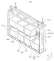
도 1은 예시적인 실시예에 따른 반송물 보관 장치를 나타내는 정면 사시도이다.
도 2는 예시적인 실시예에 따른 반송물 보관 장치를 나타내는 배면 사시도이다.이다.
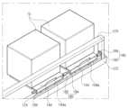
도 3은 예시적인 실시예에 따른 반송물 보관 장치의 구동부를 설명하기 위한 설명도이다.
도 4는 예시적인 실시예에 따른 반송물 보관 장치의 보조 결합부를 설명하기 위한 설명도이다.
도 5 내지 도 7은 예시적인 실시예에 따른 반송물 보관 장치의 작동을 설명하기 위한 설명도이다.Figure 1 is a front perspective view showing a return material storage device according to an exemplary embodiment.
FIG. 2 is a rear perspective view showing a return material storage device according to an exemplary embodiment.
Figure 3 is an explanatory diagram for explaining the driving unit of a return material storage device according to an exemplary embodiment.
FIG. 4 is an explanatory diagram for explaining an auxiliary coupling part of a return material storage device according to an exemplary embodiment.
Figures 5 to 7 are explanatory diagrams for explaining the operation of a return material storage device according to an exemplary embodiment.
이하, 첨부된 도면을 참조하여 본 발명의 바람직한 실시 형태들을 설명한다.Hereinafter, preferred embodiments of the present invention will be described with reference to the attached drawings.
도 1은 예시적인 실시예에 따른 반송물 보관 장치를 나타내는 정면 사시도이고, 도 2는 예시적인 실시예에 따른 반송물 보관 장치를 나타내는 배면 사시도이다.FIG. 1 is a front perspective view showing a return article storage device according to an exemplary embodiment, and FIG. 2 is a back perspective view showing a return article storage device according to an exemplary embodiment.
도 1 및 도 2를 참조하면, 반송물 보관 장치(100)는 본체 프레임(120), 적재부재(140), 구동부(160) 및 보조 결합부(180)를 포함하여 구성될 수 있다.Referring to FIGS. 1 and 2, the return material storage device (100) may be configured to include a main body frame (120), a loading member (140), a driving unit (160), and an auxiliary coupling unit (180).
본체 프레임(120)은 반송물(10)이 복수개의 층을 이루도록 배치되도록 다단 구조를 가진다. 일예로서, 본체 프레임(120)에는 제1 단부(121)와, 제1 단부(121)로부터 상부 측으로 이격 배치되는 제2 단부(122)를 구비할 수 있다. 한편, 제2 단부(122)에는 구동부(160)의 설치를 위한 설치대(123)가 구비될 수 있다. 그리고, 제2 단부(122)에는 일예로서, 도 3에 보다 자세하게 도시된 바와 같이, 적재부재(140)의 이동을 안내하기 위한 안내레일(124)이 구비될 수 있다. 이에 대한 자세한 설명은 후술하기로 한다. 또한, 본체 프레임(120)에는 상단부에 본체 프레임(120)의 설치를 위한 설치구(125)가 구비될 수 있다.The main body frame (120) has a multi-stage structure so that the return material (10) is arranged to form multiple layers. For example, the main body frame (120) may be provided with a first end (121) and a second end (122) spaced apart from the first end (121) toward the upper side. Meanwhile, the second end (122) may be provided with an installation stand (123) for installing the driving unit (160). In addition, the second end (122) may be provided with a guide rail (124) for guiding the movement of the loading member (140), as illustrated in more detail in FIG. 3, as an example. A detailed description thereof will be given later. In addition, the main body frame (120) may be provided with an installation hole (125) for installing the main body frame (120) at the upper end.
한편, 본 실시예에서는 본체 프레임(120)이 제1 단부(121)와 제2 단부(122)를 구비하는 경우를 예로 들어 설명하고 있으나, 이에 한정되지 않으며 단부의 개수는 다양하게 변경 가능할 것이다. 즉, 본체 프레임(120)은 3 단부 이상의 다단 구조를 가질 수 있다.Meanwhile, in this embodiment, a case in which the main body frame (120) has a first end (121) and a second end (122) is described as an example, but it is not limited thereto, and the number of ends may be changed in various ways. That is, the main body frame (120) may have a multi-stage structure with three or more ends.
적재부재(140)는 복수개가 본체 프레임(120)에 설치된다. 일예로서, 복수개의 적재부재(140)는 본체 프레임(120)의 하단부, 예를 들어 제1 단부(121)에 설치되는 복수개의 제1 적재부재(142)와, 제1 적재부재(142)의 상부에 배치되며 본체 프레임(120), 예를 들어 제2 단부(122)에 이동 가능하게 설치되는 복수개의 제2 적재부재(144)를 구비할 수 있다.A plurality of loading members (140) are installed on the main body frame (120). As an example, the plurality of loading members (140) may include a plurality of first loading members (142) installed on the lower part of the main body frame (120), for example, the first end (121), and a plurality of second loading members (144) positioned on the upper part of the first loading members (142) and movably installed on the main body frame (120), for example, the second end (122).
한편, 제1 적재부재(142)는 본체 프레임(120)의 제1 단부(121)에 고정 설치된다. 일예로서, 제1 적재부재(142)는 제1 단부(121)에 4개가 설치될 수 있다. 다만, 이에 한정되지 않으며 제1 적재부재(142)의 개수는 다양하게 변경 가능할 것이다. 그리고, 제1 적재부재(142)에는 반송물(10)이 적재되는 경우 반송물(10)의 이탈을 방지하기 위한 걸림턱(142a)가 구비될 수 있다. 걸림턱(142a)은 제1 적재부재(142)의 전단과 후단으로부터 상부측으로 돌출되도록 형성될 수 있다.Meanwhile, the first loading member (142) is fixedly installed to the first end (121) of the main body frame (120). As an example, four first loading members (142) may be installed to the first end (121). However, this is not limited thereto, and the number of first loading members (142) may be changed in various ways. In addition, the first loading member (142) may be provided with a catch (142a) to prevent the return material (10) from coming off when the return material (10) is loaded. The catch (142a) may be formed to protrude upward from the front and rear ends of the first loading member (142).
그리고, 제2 적재부재(144)는 본체 프레임(120)의 제2 단부(122)에 이동 가능하게 설치된다. 일예로서, 제2 적재부재(144)는 제2 단부(122)에 제1 적재부재(142)의 개수보다 하나가 적은 개수가 설치될 수 있다. 즉, 제1 적재부재(142)에 반송물(10)의 적재 및 이송이 가능할 수 있도록 복수개의 제1 적재부재(142) 중 하나의 제1 적재부재(142) 상부에 제2 적재부재(144)가 배치되지 않도록 할 수 있다. 한편, 본 실시예에서는 제2 적재부재(144)가 제2 단부(122)에 3개가 설치되는 경우를 예로 들어 설명하고 있으나, 제2 적재부재(144)의 개수는 다양하게 변경 가능할 것이다.And, the second loading member (144) is movably installed on the second end (122) of the main body frame (120). As an example, the number of second loading members (144) may be one less than the number of first loading members (142) installed on the second end (122). That is, the second loading member (144) may not be placed on top of one of the first loading members (142) among the plurality of first loading members (142) so that the loading and transport of the return material (10) onto the first loading member (142) is possible. Meanwhile, in the present embodiment, a case where three second loading members (144) are installed on the second end (122) is described as an example, but the number of second loading members (144) may be changed in various ways.
한편, 제2 적재부재(144)에도 반송물(10)의 이탈을 방지하기 위한 걸림턱(144a)이 구비될 수 있다.Meanwhile, the second loading member (144) may also be provided with a catch (144a) to prevent the return material (10) from coming off.
그리고, 제2 적재부재(144)에는 도 3에 보다 자세하게 도시된 바와 같이, 제2 단부(122)의 안내레일(124)에 결합되는 체결구(144b)가 구비될 수 있다. 즉, 체결구(144b)가 안내레일(124)에 결합되어 제2 적재부재(144)가 슬라이딩 이동 가능한 것이다. 다만, 제2 적재부재(144)의 슬라이딩 이동을 위한 구성은 안내레일(124)과 체결구(144b)에 한정되지 않으며, 다른 구성에 의해서도 구현될 수 있을 것이다.And, as illustrated in more detail in FIG. 3, the second loading member (144) may be provided with a fastening member (144b) that is coupled to the guide rail (124) of the second end (122). That is, the fastening member (144b) is coupled to the guide rail (124) so that the second loading member (144) can slide. However, the configuration for sliding movement of the second loading member (144) is not limited to the guide rail (124) and the fastening member (144b), and may also be implemented by other configurations.
구동부(160)는 복수개의 적재부재(140) 중 적어도 하나에 연결된다. 일예로서, 구동부(160)는 제2 적재부재(144) 중 적어도 어느 하나에 연결될 수 있다. 한편, 구동부(160)는 예를 들어, 구동원(162), 감속기(164), 풀리(166), 타이밍 벨트(168) 및 연결부재(170)를 포함하여 구성될 수 있다.The driving unit (160) is connected to at least one of the plurality of loading members (140). For example, the driving unit (160) may be connected to at least one of the second loading members (144). Meanwhile, the driving unit (160) may be configured to include, for example, a driving source (162), a reducer (164), a pulley (166), a timing belt (168), and a connecting member (170).
구동원(162)은 본체 프레임(120)의 설치대(123)에 고정 설치된다. 일예로서, 구동원(162)은 모터일 수 있다. 또한, 구동원(162)은 정회전과 역회전을 할 수 있다. 그리고, 구동원(162)에는 감속기(164)가 연결되며, 감속기(164)에 의해 구동원(162)으로부터 발생된 동력이 적절히 조절되어 풀리(166)로 전달될 수 있다. 풀리(166)는 타이밍 벨트(168)의 무한궤도 운동을 안내하며 2개가 하나의 쌍을 이룰 수 있다. 그리고, 구동원(162)으로부터 발생되는 구동력은 풀리(166)를 통해 타이밍 벨트(168)에 전달되고 이에 따라 타이밍 벨트(168)가 무한궤도 운동을 할 수 있다. 연결부재(170)는 타이밍 벨트(168)와 제2 적재부재(144) 중 어느 하나를 연결하는 역할을 수행한다. 이에 따라, 타이밍 벨트(168)의 주행 시 제2 적재부재(144) 중 어느 하나가 이동될 수 있다. 이와 같이, 구동원(162)의 정회전과 역회전에 의해 제2 적재부재(144)가 X 방향(도 1, 2 참조)을 따라 본체 프레임(120)의 좌측 또는 우측으로 이동될 수 있다.The driving source (162) is fixedly installed on the installation stand (123) of the main body frame (120). For example, the driving source (162) may be a motor. In addition, the driving source (162) may rotate forward and backward. In addition, a reducer (164) is connected to the driving source (162), and power generated from the driving source (162) may be appropriately controlled by the reducer (164) and transmitted to the pulley (166). The pulley (166) guides the infinite orbital motion of the timing belt (168), and two of the pulleys may form a pair. In addition, the driving force generated from the driving source (162) is transmitted to the timing belt (168) through the pulley (166), and accordingly, the timing belt (168) may perform the infinite orbital motion. The connecting member (170) serves to connect either the timing belt (168) or the second loading member (144). Accordingly, when the timing belt (168) is driven, one of the second loading members (144) can be moved. In this way, the second loading member (144) can be moved to the left or right of the main body frame (120) along the X direction (see FIGS. 1 and 2) by the forward and reverse rotation of the driving source (162).
한편, 본 실시예에서는 구동부(160)가 풀리(166)와 타이밍 벨트(168)를 구비하는 경우를 예로 들어 설명하고 있으나, 이에 한정되지 않으며 구동부(160)에는 볼 스크류 또는 복수개의 기어를 구비할 수 있으며, 이를 통해 구동원(162)로부터 발생된 구동력을 적재부재(140)에 전달할 수도 있을 것이다.Meanwhile, in this embodiment, a case in which the driving unit (160) is provided with a pulley (166) and a timing belt (168) is described as an example, but the present invention is not limited thereto, and the driving unit (160) may be provided with a ball screw or multiple gears, through which the driving force generated from the driving source (162) may be transmitted to the loading member (140).
보조 결합부(180)는 이웃하는 적재부재(140)와의 착탈을 위해 복수개의 적재부재(140) 중 일부에 구비된다. 일예로서, 보조 결합부(180)는 제2 적재부재(144)에 구비될 수 있다. 예를 들어, 보조 결합부(180)는 도 4에 보다 자세하게 도시된 바와 같이, 제2 적재부재(144)의 일단에 설치되는 전자석(182)과, 전자석(182)에 대응되도록 제2 적재부재(144)의 타단과 본체 프레임(120)에 설치되는 자성체(184)를 구비할 수 있다. 이에 대하여 보다 자세하게 살펴보면, 구동부(160)에 연결된 제2 적재부재(144)에는 전자석(182)이 구비되며, 구동부(160)가 연결된 제2 적재부재(144)에 이웃하여 배치되는 제2 적재부재(144)에는 전자석(182)에 대응되는 자성체(184)가 구비된다. 그리고, 자성체(184)가 구비되는 제2 적재부재(144)의 타단에는 전자석(182)이 구비되며, 전자석(182)에 대응되도록 이웃하여 배치되는 제2 적재부재(144)의 일단에 자성체(184)가 구비된다. 그리고, 제2 적재부재(144)의 타단에는 전자석(182)이 구비되며, 이에 대응되도록 본체 프레임(120)에 자성체(184)가 구비된다. 이와 같이, 전자석(182)과 자성체(184)로 구성되는 보조 결합부(180)를 통해 제2 적재부재(144)가 이동되는 이동 개수가 정해질 수 있다.The auxiliary coupling member (180) is provided on some of the plurality of loading members (140) for attachment and detachment from the neighboring loading members (140). As an example, the auxiliary coupling member (180) may be provided on the second loading member (144). For example, as illustrated in more detail in FIG. 4, the auxiliary coupling member (180) may be provided with an electromagnet (182) installed on one end of the second loading member (144), and a magnetic body (184) installed on the other end of the second loading member (144) and the main body frame (120) to correspond to the electromagnet (182). Looking into this in more detail, an electromagnet (182) is provided on the second loading member (144) connected to the driving member (160), and a magnetic body (184) corresponding to the electromagnet (182) is provided on the second loading member (144) arranged adjacent to the second loading member (144) to which the driving member (160) is connected. In addition, an electromagnet (182) is provided on the other end of the second loading member (144) on which the magnetic body (184) is provided, and a magnetic body (184) is provided on one end of the second loading member (144) arranged adjacent to the electromagnet (182). In addition, an electromagnet (182) is provided on the other end of the second loading member (144), and a magnetic body (184) is provided on the main body frame (120) to correspond thereto. In this way, the number of times the second loading member (144) moves can be determined through the auxiliary coupling member (180) composed of an electromagnet (182) and a magnetic body (184).
여기서, 설명의 편의를 위해 구동부(160)에 연결된 제2 적재부재(144)를 제2-1 적재부재라 하고, 제2-1 적재부재에 이웃하여 배치되는 제2 적재부재(144)를 제2-2 적재부재라 하며, 제2-2 적재부재에 이웃하여 배치되는 제2 적재부재(144)를 제2-3 적재부재라 한다.Here, for convenience of explanation, the second loading member (144) connected to the driving member (160) is referred to as the 2-1 loading member, the second loading member (144) arranged adjacent to the 2-1 loading member is referred to as the 2-2 loading member, and the second loading member (144) arranged adjacent to the 2-2 loading member is referred to as the 2-3 loading member.
제2-1 적재부재에 구비되는 전자석(182)이 작동되는 경우 제2-2 적재부재에 구비되는 자성체(184)가 제2-1 적재부재에 구비되는 전자석(182)에 결합된다. 이에 따라, 제2-1 적재부재와 제2-2 적재부재가 함께 이동될 수 있다. 반대로, 제2-1 적재부재에 구비되는 전자석(182)이 작동되지 않는 경우 제2-2 적재부재에 구비되는 자성체(184)가 제2-1 적재부재에 구비되는 전자석(182)으로부터 분리될 수 있다. 이에 따라, 제2-1 적재부재는 제2-2 적재부재와 함께 이동되지 않고 제2-1 적재부재만이 구동부(160)의 구동에 의해 이동될 수 있다.When the electromagnet (182) provided in the 2-1 loading member is operated, the magnetic body (184) provided in the 2-2 loading member is coupled to the electromagnet (182) provided in the 2-1 loading member. Accordingly, the 2-1 loading member and the 2-2 loading member can be moved together. Conversely, when the electromagnet (182) provided in the 2-1 loading member is not operated, the magnetic body (184) provided in the 2-2 loading member can be separated from the electromagnet (182) provided in the 2-1 loading member. Accordingly, the 2-1 loading member is not moved together with the 2-2 loading member, and only the 2-1 loading member can be moved by the driving of the driving unit (160).
그리고, 제2-2 적재부재에 구비되는 전자석(182)이 작동되는 경우 제2-3 적재부재에 구비되는 자성체(184)가 제2-2 적재부재에 구비되는 전자석(182)에 결합된다. 이에 따라, 제2-2 적재부재와 제2-3 적재부재가 함께 이동될 수 있다. 다만, 제2-3 적재부재가 이동되는 경우 제2-3 적재부재에 구비되는 전자석(182)이 작동되지 않을 수 있다.And, when the electromagnet (182) provided in the 2-2 loading member is operated, the magnetic body (184) provided in the 2-3 loading member is coupled to the electromagnet (182) provided in the 2-2 loading member. Accordingly, the 2-2 loading member and the 2-3 loading member can be moved together. However, when the 2-3 loading member is moved, the electromagnet (182) provided in the 2-3 loading member may not be operated.
이에 대한 자세한 설명은 후술하기로 한다.A detailed explanation of this will be given later.
한편, 본 실시예에서는 보조 결합부(180)가 전자석(182)과 자성체(184)로 구성되는 경우를 예로 들어 설명하고 있으나, 이에 한정되지 않으며 보조 결합부(180)는 캠, 솔레노이드 등을 포함하여 구성될 수도 있다.Meanwhile, in this embodiment, the auxiliary coupling part (180) is described as an example in which it is composed of an electromagnet (182) and a magnetic body (184), but it is not limited thereto, and the auxiliary coupling part (180) may be composed of a cam, a solenoid, etc.
상기한 바와 같이, 구동부(160)와 보조 결합부(180)를 통해 복수개의 제2 적재부재(144) 중 일부 또는 전부를 이동시킬 수 있으므로, 반송물(10)이 복수개의 층을 이루도록 본체 프레임(120)에 적재될 수 있다. 나아가, 반송물(10)이 복수개의 층을 이루도록 적재부재(140)에 적재되면서도 반송물(10)의 이송 및 적재가 용이하게 수행될 수 있다. 다시 말해, 반도체 제조 라인에 구비되는 반송물 이송 장치(OHT, 미도시)의 구조나 구성부품의 변경 없이 기존의 반송물 이송 장치(OHT)를 통해 반송물(10)의 이송 및 적재가 수행될 수 있다.As described above, since some or all of the plurality of second loading members (144) can be moved through the driving unit (160) and the auxiliary coupling unit (180), the return material (10) can be loaded onto the main body frame (120) to form a plurality of layers. Furthermore, even when the return material (10) is loaded onto the loading member (140) to form a plurality of layers, the transport and loading of the return material (10) can be easily performed. In other words, the transport and loading of the return material (10) can be performed through an existing return material transport device (OHT, not shown) equipped in a semiconductor manufacturing line without changing the structure or components of the return material transport device (OHT).
이하에서는 도면을 참조하여 반송물 보관 장치의 작동에 대하여 설명하기로 한다.Below, the operation of the return storage device will be described with reference to the drawings.
도 5 내지 도 7은 예시적인 실시예에 따른 반송물 보관 장치의 작동을 설명하기 위한 설명도이다.Figures 5 to 7 are explanatory diagrams for explaining the operation of a return material storage device according to an exemplary embodiment.
도 5를 참조하면, 본체 프레임(120)의 제1 단부(121)에 적재된 반송물(10) 중 좌측에서 3번째 배치되는 반송물(10)을 이송하고자 하는 경우 구동부(160)가 연결된 제2 적재부재(144)만이 X축 방향 오른쪽으로 이동된다. 이때, 구동부(160)가 연결된 제2 적재부재(144)에 구비되는 전자석(182)은 작동하지 않으며, 나머지 제2 적재부재(144)에 구비되는 전자석(182)은 작동한다. 이에 따라, 나머지 제2 적재부재(144)는 이동되지 않을 수 있으므로 본체 프레임(120)의 제1 단부(121)에 적재된 반송물(10) 중 좌측에서 3번째 배치되는 반송물(10)을 이송시킬 수 있다.Referring to Fig. 5, when transporting the third load (10) from the left among the loads (10) loaded on the first end (121) of the main body frame (120), only the second loading member (144) connected to the driving unit (160) moves to the right in the X-axis direction. At this time, the electromagnet (182) provided in the second loading member (144) connected to the driving unit (160) does not operate, and the electromagnets (182) provided in the remaining second loading members (144) operate. Accordingly, the remaining second loading members (144) may not move, so that the third load (10) from the left among the loads (10) loaded on the first end (121) of the main body frame (120) can be transported.
그리고, 도 6을 참조하면, 본체 프레임(120)의 제1 단부(121)에 적재된 반송물(10) 중 좌측에서 2번째 배치되는 반송물(10)을 이송하고자 하는 경우 구동부(160)가 연결된 제2 적재부재(144)와 이웃하는 제2 적재부재(144)가 X축 방향 오른쪽으로 이동된다. 이때, 구동부(160)가 연결된 적재부재(144)에 구비되는 전자석(182)은 작동하고, 구동부(160)가 연결된 적재부재(144)에 이웃하여 배치되는 적재부재(144)에 구비되는 전자석(182)은 작동하지 않는다. 그리고, 나머지 하나의 적재부재(144)에 구비되는 전자석(182)은 작동하여 본체 프레임(120)에 설치되는 자성체(184)와 결합된다. 이에 따라, 본체 프레임(120)의 제1 단부(121)에 적재된 반송물(10) 중 좌측에서 2번째 배치되는 반송물(10)을 이송시킬 수 있다.And, referring to Fig. 6, when transporting the second load member (10) from the left among the load members (10) loaded on the first end (121) of the main body frame (120), the second load member (144) connected to the driving unit (160) and the neighboring second load member (144) move to the right in the X-axis direction. At this time, the electromagnet (182) provided in the load member (144) connected to the driving unit (160) operates, and the electromagnet (182) provided in the load member (144) located adjacent to the load member (144) connected to the driving unit (160) does not operate. And, the electromagnet (182) provided in the remaining one load member (144) operates and is coupled with the magnetic body (184) installed in the main body frame (120). Accordingly, the second load (10) placed from the left among the loads (10) loaded on the first end (121) of the main body frame (120) can be transported.
또한, 도 7을 참조하면, 본체 프레임(120)의 제1 단부(121)에 적재된 반송물(10) 중 좌측에서 1번째 배치되는 반송물(10)을 이송하고자 하는 경우 모든 제2 적재부재(144)가 X축 방향 오른쪽으로 이동된다. 이때, 본체 프레임(120)에 설치되는 자성체(184)에 대응되는 전자석(182)만이 작동되지 않고 나머지 전자석(182)은 모두 작동된다. 이에 따라, 본체 프레임(120)의 제1 단부(121)에 적재된 반송물(10) 중 좌측에서 1번째 배치되는 반송물(10)을 이송시킬 수 있다.In addition, referring to FIG. 7, when transporting the first load (10) placed from the left among the loads (10) loaded on the first end (121) of the main body frame (120), all second loading members (144) move to the right in the X-axis direction. At this time, only the electromagnet (182) corresponding to the magnetic body (184) installed on the main body frame (120) does not operate, and all of the remaining electromagnets (182) operate. Accordingly, the load (10) placed from the left among the loads (10) loaded on the first end (121) of the main body frame (120) can be transported.
이상에서 본 발명의 실시예에 대하여 상세하게 설명하였지만 본 발명의 권리범위는 이에 한정되는 것은 아니고, 청구범위에 기재된 본 발명의 기술적 사상을 벗어나지 않는 범위 내에서 다양한 수정 및 변형이 가능하다는 것은 당 기술분야의 통상의 지식을 가진 자에게는 자명할 것이다.Although the embodiments of the present invention have been described in detail above, the scope of the present invention is not limited thereto, and it will be apparent to those skilled in the art that various modifications and variations are possible within a scope that does not depart from the technical spirit of the present invention described in the claims.
100 : 반송물 보관 장치
120 : 본체 프레임
140 : 적재부재
160 : 구동부
180 : 보조 결합부100 : Return storage device
120 : Body Frame
140 : No loading
160 : Drive Unit
180 : Auxiliary joint
Claims (8)
Translated fromKorean반송물이 복수개의 층을 이루도록 상기 다단 구조의 상기 본체 프레임에 배치되는 복수개의 적재부재;
상기 복수개의 적재부재 중 적어도 하나에 연결되는 구동부; 및
이웃하는 적재부재와의 착탈을 위해 상기 복수개의 적재부재 중 일부에 구비되는 보조 결합부;
를 포함하며,
상기 복수개의 적재부재는 상기 본체 프레임의 하단부에 고정 설치되는 복수개의 제1 적재부재와, 상기 제1 적재부재의 상부에 배치되며 상기 본체 프레임에 이동 가능하게 설치되는 복수개의 제2 적재부재를 구비하며,
상기 구동부는 상기 복수개의 제2 적재부재 중 적어도 어느 하나에 연결되며,
상기 보조 결합부는 상기 제2 적재부재의 일단에 설치되는 전자석과, 상기 전자석에 대응되도록 상기 제2 적재부재의 타단과 상기 본체 프레임에 설치되는 자성체를 구비하는 반송물 보관 장치.
A main body frame having a multi-stage structure;
A plurality of loading members arranged on the main body frame of the multi-stage structure so that the returned goods form multiple layers;
a driving unit connected to at least one of the plurality of loading members; and
An auxiliary connecting member provided on some of the plurality of loading members for attachment or detachment from adjacent loading members;
Including,
The above plurality of loading members comprises a plurality of first loading members fixedly installed at the lower end of the main body frame, and a plurality of second loading members arranged above the first loading members and movably installed on the main body frame.
The above driving member is connected to at least one of the plurality of second loading members,
A return material storage device having an electromagnet installed at one end of the second loading member and a magnetic body installed at the other end of the second loading member and the main body frame to correspond to the electromagnet.
상기 구동부는 상기 본체 프레임에 고정 설치되는 구동원과, 상기 구동원에 연결되어 동력을 전달하는 동력전달부재 및 상기 동력전달부재와 상기 제2 적재부재를 연결하는 연결부재를 구비하며,
상기 동력전달부재는 풀리와, 상기 풀리에 연결되는 타이밍 벨트를 구비하는 반송물 보관 장치.
In the first paragraph,
The above driving unit has a driving source fixedly installed on the main body frame, a power transmission member connected to the driving source to transmit power, and a connecting member connecting the power transmission member and the second loading member.
The above power transmission member is a return material storage device having a pulley and a timing belt connected to the pulley.
상기 구동부는 상기 풀리와 상기 구동원을 연결하는 감속기를 더 구비하는 반송물 보관 장치.
In the second paragraph,
A return material storage device wherein the above driving unit further comprises a reducer connecting the pulley and the driving source.
상기 본체 프레임에는 상기 제2 적재부재의 이동을 위한 안내레일이 구비되는 반송물 보관 장치.
In the first paragraph,
A return material storage device in which a guide rail for moving the second loading member is provided on the above main body frame.
상기 복수개의 적재부재에는 상기 반송물의 이탈을 방지하기 위한 걸림턱이 구비되는 반송물 보관 장치.
In the first paragraph,
A return material storage device in which the above plurality of loading members are provided with a catch to prevent the return material from falling off.
상기 복수개의 적재부재는 2개의 층을 이루도록 배치되는 반송물 보관 장치.
In the first paragraph,
A return material storage device in which the above plurality of loading members are arranged to form two layers.
상기 제1 적재부재의 개수는 상기 제2 적재부재의 개수보다 하나가 많은 반송물 보관 장치.
In Article 6,
A return material storage device in which the number of the first loading members is one more than the number of the second loading members.
상기 구동부와 상기 보조 결합부를 통해 상기 복수개의 제2 적재부재 중 일부 또는 전부를 이동시키는 반송물 보관 장치.
In the first paragraph,
A return material storage device that moves some or all of the plurality of second loading members through the driving unit and the auxiliary coupling unit.
Priority Applications (2)
| Application Number | Priority Date | Filing Date | Title |
|---|---|---|---|
| KR1020200149494AKR102801222B1 (en) | 2020-11-10 | 2020-11-10 | Apparatus for storage of carrying material |
| US17/517,963US12006144B2 (en) | 2020-11-10 | 2021-11-03 | Apparatus for storage of carrying material |
Applications Claiming Priority (1)
| Application Number | Priority Date | Filing Date | Title |
|---|---|---|---|
| KR1020200149494AKR102801222B1 (en) | 2020-11-10 | 2020-11-10 | Apparatus for storage of carrying material |
Publications (2)
| Publication Number | Publication Date |
|---|---|
| KR20220063853A KR20220063853A (en) | 2022-05-18 |
| KR102801222B1true KR102801222B1 (en) | 2025-04-30 |
Family
ID=81455088
Family Applications (1)
| Application Number | Title | Priority Date | Filing Date |
|---|---|---|---|
| KR1020200149494AActiveKR102801222B1 (en) | 2020-11-10 | 2020-11-10 | Apparatus for storage of carrying material |
Country Status (2)
| Country | Link |
|---|---|
| US (1) | US12006144B2 (en) |
| KR (1) | KR102801222B1 (en) |
Citations (1)
| Publication number | Priority date | Publication date | Assignee | Title |
|---|---|---|---|---|
| JP2020075819A (en) | 2018-11-06 | 2020-05-21 | 村田機械株式会社 | Ceiling hanging shelf and transport system |
Family Cites Families (14)
| Publication number | Priority date | Publication date | Assignee | Title |
|---|---|---|---|---|
| KR100577622B1 (en)* | 2001-12-04 | 2006-05-10 | 로제 가부시키가이샤 | Device for temporarily loading, keeping and unloading a container |
| WO2004034438A2 (en) | 2002-10-11 | 2004-04-22 | Brooks Automation, Inc. | Access to one or more levels of material storage shelves by an overhead hoist transport vehicle from a single track position |
| US7578650B2 (en)* | 2004-07-29 | 2009-08-25 | Kla-Tencor Technologies Corporation | Quick swap load port |
| JP2008172062A (en) | 2007-01-12 | 2008-07-24 | Murata Mach Ltd | Article feeding apparatus |
| TW200911654A (en) | 2007-09-06 | 2009-03-16 | Asyst Technologies Japan Inc | Storage, transporting system and storage set |
| US8070410B2 (en)* | 2008-02-05 | 2011-12-06 | Lutz Rebstock | Scalable stocker with automatic handling buffer |
| JP4770938B2 (en) | 2009-02-10 | 2011-09-14 | 東京エレクトロン株式会社 | Substrate processing equipment |
| TWI496732B (en) | 2009-07-31 | 2015-08-21 | Murata Machinery Ltd | Buffered storage and transport device for tool utilization |
| KR101123888B1 (en) | 2010-03-11 | 2012-03-23 | (주) 예스티 | Foup stocker and heat treatment apparatus with the same |
| KR102174332B1 (en)* | 2014-07-30 | 2020-11-04 | 삼성전자주식회사 | Stockers of Fabricating Semiconductors and Wafer Transferring Method Using the Same |
| KR101674454B1 (en) | 2015-06-22 | 2016-11-09 | 주식회사 신성에프에이 | Side track buffer for foup purging |
| KR102453197B1 (en)* | 2015-10-30 | 2022-10-12 | 삼성전자주식회사 | Apparatus for loading substrate storage container |
| KR102141197B1 (en)* | 2018-11-28 | 2020-08-04 | 세메스 주식회사 | Carrier buffer apparatus |
| KR102167241B1 (en)* | 2019-01-02 | 2020-10-19 | 김재기 | How Smart Storage and Storage Works |
- 2020
- 2020-11-10KRKR1020200149494Apatent/KR102801222B1/enactiveActive
- 2021
- 2021-11-03USUS17/517,963patent/US12006144B2/enactiveActive
Patent Citations (1)
| Publication number | Priority date | Publication date | Assignee | Title |
|---|---|---|---|---|
| JP2020075819A (en) | 2018-11-06 | 2020-05-21 | 村田機械株式会社 | Ceiling hanging shelf and transport system |
Also Published As
| Publication number | Publication date |
|---|---|
| US12006144B2 (en) | 2024-06-11 |
| US20220144542A1 (en) | 2022-05-12 |
| KR20220063853A (en) | 2022-05-18 |
Similar Documents
| Publication | Publication Date | Title |
|---|---|---|
| JP7324422B2 (en) | Ceiling hanging shelf and transport system | |
| KR100679938B1 (en) | Ceiling odometer system | |
| CA2350562C (en) | Transfer system | |
| US20060254883A1 (en) | Chain-type conveyor having direction-changing roller | |
| US20070224026A1 (en) | Transferring system | |
| CN113471117B (en) | Tower crane, method for driving tower crane, and machine-readable medium | |
| JPH11157604A (en) | Automated storage and retrieval system | |
| EP3643646A1 (en) | Lifting device and sorting device | |
| KR100342254B1 (en) | Loading robot having a balancing part | |
| KR102801222B1 (en) | Apparatus for storage of carrying material | |
| TWM651796U (en) | Reciprocating conveyor | |
| CN107324253B (en) | Bidirectional pallet fork device | |
| US4461379A (en) | Pallet conveyor | |
| JP2010046706A (en) | Apparatus for carrying workpiece | |
| KR19980067155A (en) | Recirculating Component Feeder | |
| JPH0717605A (en) | Load transfer device | |
| JP2016204154A (en) | Lifting conveyance system, and transfer device | |
| CN108177960A (en) | A kind of conveying device | |
| JP2004203528A (en) | Load transporting method, load transporting device, stacker crane, and automatic warehouse | |
| KR20230093764A (en) | lift-type transport device | |
| JPH04308104A (en) | Material carrying-in/carrying-out device | |
| JP7318676B2 (en) | Conveyor | |
| EP2090531A1 (en) | Chain-type conveyor having direction-changing roller | |
| CN112573051A (en) | Article conveying device | |
| JPS6238965Y2 (en) |
Legal Events
| Date | Code | Title | Description |
|---|---|---|---|
| PA0109 | Patent application | Patent event code:PA01091R01D Comment text:Patent Application Patent event date:20201110 | |
| PG1501 | Laying open of application | ||
| A201 | Request for examination | ||
| PA0201 | Request for examination | Patent event code:PA02012R01D Patent event date:20231108 Comment text:Request for Examination of Application Patent event code:PA02011R01I Patent event date:20201110 Comment text:Patent Application | |
| E902 | Notification of reason for refusal | ||
| PE0902 | Notice of grounds for rejection | Comment text:Notification of reason for refusal Patent event date:20241218 Patent event code:PE09021S01D | |
| E701 | Decision to grant or registration of patent right | ||
| PE0701 | Decision of registration | Patent event code:PE07011S01D Comment text:Decision to Grant Registration Patent event date:20250313 | |
| GRNT | Written decision to grant | ||
| PR0701 | Registration of establishment | Comment text:Registration of Establishment Patent event date:20250423 Patent event code:PR07011E01D | |
| PR1002 | Payment of registration fee | Payment date:20250424 End annual number:3 Start annual number:1 | |
| PG1601 | Publication of registration |