KR102799402B1 - Systems and methods for charging, transporting and operating flying machines - Google Patents
Systems and methods for charging, transporting and operating flying machinesDownload PDFInfo
- Publication number
- KR102799402B1 KR102799402B1KR1020187028086AKR20187028086AKR102799402B1KR 102799402 B1KR102799402 B1KR 102799402B1KR 1020187028086 AKR1020187028086 AKR 1020187028086AKR 20187028086 AKR20187028086 AKR 20187028086AKR 102799402 B1KR102799402 B1KR 102799402B1
- Authority
- KR
- South Korea
- Prior art keywords
- flying
- delete delete
- charging
- storage container
- machines
- Prior art date
- Legal status (The legal status is an assumption and is not a legal conclusion. Google has not performed a legal analysis and makes no representation as to the accuracy of the status listed.)
- Active
Links
Images


Classifications
- B—PERFORMING OPERATIONS; TRANSPORTING
- B64—AIRCRAFT; AVIATION; COSMONAUTICS
- B64F—GROUND OR AIRCRAFT-CARRIER-DECK INSTALLATIONS SPECIALLY ADAPTED FOR USE IN CONNECTION WITH AIRCRAFT; DESIGNING, MANUFACTURING, ASSEMBLING, CLEANING, MAINTAINING OR REPAIRING AIRCRAFT, NOT OTHERWISE PROVIDED FOR; HANDLING, TRANSPORTING, TESTING OR INSPECTING AIRCRAFT COMPONENTS, NOT OTHERWISE PROVIDED FOR
- B64F5/00—Designing, manufacturing, assembling, cleaning, maintaining or repairing aircraft, not otherwise provided for; Handling, transporting, testing or inspecting aircraft components, not otherwise provided for
- B64F5/60—Testing or inspecting aircraft components or systems
- B—PERFORMING OPERATIONS; TRANSPORTING
- B64—AIRCRAFT; AVIATION; COSMONAUTICS
- B64C—AEROPLANES; HELICOPTERS
- B64C39/00—Aircraft not otherwise provided for
- B64C39/02—Aircraft not otherwise provided for characterised by special use
- B64C39/024—Aircraft not otherwise provided for characterised by special use of the remote controlled vehicle type, i.e. RPV
- B—PERFORMING OPERATIONS; TRANSPORTING
- B60—VEHICLES IN GENERAL
- B60L—PROPULSION OF ELECTRICALLY-PROPELLED VEHICLES; SUPPLYING ELECTRIC POWER FOR AUXILIARY EQUIPMENT OF ELECTRICALLY-PROPELLED VEHICLES; ELECTRODYNAMIC BRAKE SYSTEMS FOR VEHICLES IN GENERAL; MAGNETIC SUSPENSION OR LEVITATION FOR VEHICLES; MONITORING OPERATING VARIABLES OF ELECTRICALLY-PROPELLED VEHICLES; ELECTRIC SAFETY DEVICES FOR ELECTRICALLY-PROPELLED VEHICLES
- B60L53/00—Methods of charging batteries, specially adapted for electric vehicles; Charging stations or on-board charging equipment therefor; Exchange of energy storage elements in electric vehicles
- B60L53/10—Methods of charging batteries, specially adapted for electric vehicles; Charging stations or on-board charging equipment therefor; Exchange of energy storage elements in electric vehicles characterised by the energy transfer between the charging station and the vehicle
- B60L53/14—Conductive energy transfer
- B60L53/16—Connectors, e.g. plugs or sockets, specially adapted for charging electric vehicles
- B—PERFORMING OPERATIONS; TRANSPORTING
- B60—VEHICLES IN GENERAL
- B60L—PROPULSION OF ELECTRICALLY-PROPELLED VEHICLES; SUPPLYING ELECTRIC POWER FOR AUXILIARY EQUIPMENT OF ELECTRICALLY-PROPELLED VEHICLES; ELECTRODYNAMIC BRAKE SYSTEMS FOR VEHICLES IN GENERAL; MAGNETIC SUSPENSION OR LEVITATION FOR VEHICLES; MONITORING OPERATING VARIABLES OF ELECTRICALLY-PROPELLED VEHICLES; ELECTRIC SAFETY DEVICES FOR ELECTRICALLY-PROPELLED VEHICLES
- B60L53/00—Methods of charging batteries, specially adapted for electric vehicles; Charging stations or on-board charging equipment therefor; Exchange of energy storage elements in electric vehicles
- B60L53/30—Constructional details of charging stations
- B60L53/305—Communication interfaces
- B—PERFORMING OPERATIONS; TRANSPORTING
- B60—VEHICLES IN GENERAL
- B60L—PROPULSION OF ELECTRICALLY-PROPELLED VEHICLES; SUPPLYING ELECTRIC POWER FOR AUXILIARY EQUIPMENT OF ELECTRICALLY-PROPELLED VEHICLES; ELECTRODYNAMIC BRAKE SYSTEMS FOR VEHICLES IN GENERAL; MAGNETIC SUSPENSION OR LEVITATION FOR VEHICLES; MONITORING OPERATING VARIABLES OF ELECTRICALLY-PROPELLED VEHICLES; ELECTRIC SAFETY DEVICES FOR ELECTRICALLY-PROPELLED VEHICLES
- B60L53/00—Methods of charging batteries, specially adapted for electric vehicles; Charging stations or on-board charging equipment therefor; Exchange of energy storage elements in electric vehicles
- B60L53/50—Charging stations characterised by energy-storage or power-generation means
- B60L53/53—Batteries
- B—PERFORMING OPERATIONS; TRANSPORTING
- B64—AIRCRAFT; AVIATION; COSMONAUTICS
- B64F—GROUND OR AIRCRAFT-CARRIER-DECK INSTALLATIONS SPECIALLY ADAPTED FOR USE IN CONNECTION WITH AIRCRAFT; DESIGNING, MANUFACTURING, ASSEMBLING, CLEANING, MAINTAINING OR REPAIRING AIRCRAFT, NOT OTHERWISE PROVIDED FOR; HANDLING, TRANSPORTING, TESTING OR INSPECTING AIRCRAFT COMPONENTS, NOT OTHERWISE PROVIDED FOR
- B64F1/00—Ground or aircraft-carrier-deck installations
- B64F1/12—Ground or aircraft-carrier-deck installations for anchoring aircraft
- B64F1/16—Pickets or ground anchors; Wheel chocks
- B—PERFORMING OPERATIONS; TRANSPORTING
- B64—AIRCRAFT; AVIATION; COSMONAUTICS
- B64U—UNMANNED AERIAL VEHICLES [UAV]; EQUIPMENT THEREFOR
- B64U10/00—Type of UAV
- B64U10/10—Rotorcrafts
- B—PERFORMING OPERATIONS; TRANSPORTING
- B64—AIRCRAFT; AVIATION; COSMONAUTICS
- B64U—UNMANNED AERIAL VEHICLES [UAV]; EQUIPMENT THEREFOR
- B64U10/00—Type of UAV
- B64U10/10—Rotorcrafts
- B64U10/13—Flying platforms
- B64U10/14—Flying platforms with four distinct rotor axes, e.g. quadcopters
- B—PERFORMING OPERATIONS; TRANSPORTING
- B64—AIRCRAFT; AVIATION; COSMONAUTICS
- B64U—UNMANNED AERIAL VEHICLES [UAV]; EQUIPMENT THEREFOR
- B64U10/00—Type of UAV
- B64U10/25—Fixed-wing aircraft
- B—PERFORMING OPERATIONS; TRANSPORTING
- B64—AIRCRAFT; AVIATION; COSMONAUTICS
- B64U—UNMANNED AERIAL VEHICLES [UAV]; EQUIPMENT THEREFOR
- B64U30/00—Means for producing lift; Empennages; Arrangements thereof
- B64U30/10—Wings
- B—PERFORMING OPERATIONS; TRANSPORTING
- B64—AIRCRAFT; AVIATION; COSMONAUTICS
- B64U—UNMANNED AERIAL VEHICLES [UAV]; EQUIPMENT THEREFOR
- B64U30/00—Means for producing lift; Empennages; Arrangements thereof
- B64U30/20—Rotors; Rotor supports
- B—PERFORMING OPERATIONS; TRANSPORTING
- B64—AIRCRAFT; AVIATION; COSMONAUTICS
- B64U—UNMANNED AERIAL VEHICLES [UAV]; EQUIPMENT THEREFOR
- B64U50/00—Propulsion; Power supply
- B64U50/10—Propulsion
- B64U50/19—Propulsion using electrically powered motors
- B—PERFORMING OPERATIONS; TRANSPORTING
- B64—AIRCRAFT; AVIATION; COSMONAUTICS
- B64U—UNMANNED AERIAL VEHICLES [UAV]; EQUIPMENT THEREFOR
- B64U50/00—Propulsion; Power supply
- B64U50/30—Supply or distribution of electrical power
- B64U50/34—In-flight charging
- B—PERFORMING OPERATIONS; TRANSPORTING
- B64—AIRCRAFT; AVIATION; COSMONAUTICS
- B64U—UNMANNED AERIAL VEHICLES [UAV]; EQUIPMENT THEREFOR
- B64U50/00—Propulsion; Power supply
- B64U50/30—Supply or distribution of electrical power
- B64U50/37—Charging when not in flight
- B—PERFORMING OPERATIONS; TRANSPORTING
- B64—AIRCRAFT; AVIATION; COSMONAUTICS
- B64U—UNMANNED AERIAL VEHICLES [UAV]; EQUIPMENT THEREFOR
- B64U80/00—Transport or storage specially adapted for UAVs
- B64U80/20—Transport or storage specially adapted for UAVs with arrangements for servicing the UAV
- B64U80/25—Transport or storage specially adapted for UAVs with arrangements for servicing the UAV for recharging batteries; for refuelling
- G—PHYSICS
- G01—MEASURING; TESTING
- G01M—TESTING STATIC OR DYNAMIC BALANCE OF MACHINES OR STRUCTURES; TESTING OF STRUCTURES OR APPARATUS, NOT OTHERWISE PROVIDED FOR
- G01M99/00—Subject matter not provided for in other groups of this subclass
- G01M99/005—Testing of complete machines, e.g. washing-machines or mobile phones
- G—PHYSICS
- G01—MEASURING; TESTING
- G01M—TESTING STATIC OR DYNAMIC BALANCE OF MACHINES OR STRUCTURES; TESTING OF STRUCTURES OR APPARATUS, NOT OTHERWISE PROVIDED FOR
- G01M99/00—Subject matter not provided for in other groups of this subclass
- G01M99/008—Subject matter not provided for in other groups of this subclass by doing functionality tests
- G—PHYSICS
- G05—CONTROLLING; REGULATING
- G05D—SYSTEMS FOR CONTROLLING OR REGULATING NON-ELECTRIC VARIABLES
- G05D1/00—Control of position, course, altitude or attitude of land, water, air or space vehicles, e.g. using automatic pilots
- G05D1/60—Intended control result
- G05D1/652—Take-off
- H—ELECTRICITY
- H02—GENERATION; CONVERSION OR DISTRIBUTION OF ELECTRIC POWER
- H02J—CIRCUIT ARRANGEMENTS OR SYSTEMS FOR SUPPLYING OR DISTRIBUTING ELECTRIC POWER; SYSTEMS FOR STORING ELECTRIC ENERGY
- H02J7/00—Circuit arrangements for charging or depolarising batteries or for supplying loads from batteries
- H02J7/0042—Circuit arrangements for charging or depolarising batteries or for supplying loads from batteries characterised by the mechanical construction
- B—PERFORMING OPERATIONS; TRANSPORTING
- B60—VEHICLES IN GENERAL
- B60L—PROPULSION OF ELECTRICALLY-PROPELLED VEHICLES; SUPPLYING ELECTRIC POWER FOR AUXILIARY EQUIPMENT OF ELECTRICALLY-PROPELLED VEHICLES; ELECTRODYNAMIC BRAKE SYSTEMS FOR VEHICLES IN GENERAL; MAGNETIC SUSPENSION OR LEVITATION FOR VEHICLES; MONITORING OPERATING VARIABLES OF ELECTRICALLY-PROPELLED VEHICLES; ELECTRIC SAFETY DEVICES FOR ELECTRICALLY-PROPELLED VEHICLES
- B60L2200/00—Type of vehicles
- B60L2200/10—Air crafts
- B—PERFORMING OPERATIONS; TRANSPORTING
- B64—AIRCRAFT; AVIATION; COSMONAUTICS
- B64U—UNMANNED AERIAL VEHICLES [UAV]; EQUIPMENT THEREFOR
- B64U2201/00—UAVs characterised by their flight controls
- B64U2201/10—UAVs characterised by their flight controls autonomous, i.e. by navigating independently from ground or air stations, e.g. by using inertial navigation systems [INS]
- B—PERFORMING OPERATIONS; TRANSPORTING
- B64—AIRCRAFT; AVIATION; COSMONAUTICS
- B64U—UNMANNED AERIAL VEHICLES [UAV]; EQUIPMENT THEREFOR
- B64U70/00—Launching, take-off or landing arrangements
- B—PERFORMING OPERATIONS; TRANSPORTING
- B64—AIRCRAFT; AVIATION; COSMONAUTICS
- B64U—UNMANNED AERIAL VEHICLES [UAV]; EQUIPMENT THEREFOR
- B64U80/00—Transport or storage specially adapted for UAVs
- B64U80/70—Transport or storage specially adapted for UAVs in containers
- G—PHYSICS
- G05—CONTROLLING; REGULATING
- G05D—SYSTEMS FOR CONTROLLING OR REGULATING NON-ELECTRIC VARIABLES
- G05D2109/00—Types of controlled vehicles
- G05D2109/20—Aircraft, e.g. drones
- G05D2109/25—Rotorcrafts
- G05D2109/254—Flying platforms, e.g. multicopters
- G—PHYSICS
- G08—SIGNALLING
- G08G—TRAFFIC CONTROL SYSTEMS
- G08G5/00—Traffic control systems for aircraft
- G08G5/20—Arrangements for acquiring, generating, sharing or displaying traffic information
- G08G5/26—Transmission of traffic-related information between aircraft and ground stations
- G—PHYSICS
- G08—SIGNALLING
- G08G—TRAFFIC CONTROL SYSTEMS
- G08G5/00—Traffic control systems for aircraft
- G08G5/50—Navigation or guidance aids
- G08G5/55—Navigation or guidance aids for a single aircraft
- G—PHYSICS
- G08—SIGNALLING
- G08G—TRAFFIC CONTROL SYSTEMS
- G08G5/00—Traffic control systems for aircraft
- G08G5/50—Navigation or guidance aids
- G08G5/57—Navigation or guidance aids for unmanned aircraft
- Y—GENERAL TAGGING OF NEW TECHNOLOGICAL DEVELOPMENTS; GENERAL TAGGING OF CROSS-SECTIONAL TECHNOLOGIES SPANNING OVER SEVERAL SECTIONS OF THE IPC; TECHNICAL SUBJECTS COVERED BY FORMER USPC CROSS-REFERENCE ART COLLECTIONS [XRACs] AND DIGESTS
- Y02—TECHNOLOGIES OR APPLICATIONS FOR MITIGATION OR ADAPTATION AGAINST CLIMATE CHANGE
- Y02T—CLIMATE CHANGE MITIGATION TECHNOLOGIES RELATED TO TRANSPORTATION
- Y02T10/00—Road transport of goods or passengers
- Y02T10/60—Other road transportation technologies with climate change mitigation effect
- Y02T10/70—Energy storage systems for electromobility, e.g. batteries
- Y—GENERAL TAGGING OF NEW TECHNOLOGICAL DEVELOPMENTS; GENERAL TAGGING OF CROSS-SECTIONAL TECHNOLOGIES SPANNING OVER SEVERAL SECTIONS OF THE IPC; TECHNICAL SUBJECTS COVERED BY FORMER USPC CROSS-REFERENCE ART COLLECTIONS [XRACs] AND DIGESTS
- Y02—TECHNOLOGIES OR APPLICATIONS FOR MITIGATION OR ADAPTATION AGAINST CLIMATE CHANGE
- Y02T—CLIMATE CHANGE MITIGATION TECHNOLOGIES RELATED TO TRANSPORTATION
- Y02T10/00—Road transport of goods or passengers
- Y02T10/60—Other road transportation technologies with climate change mitigation effect
- Y02T10/7072—Electromobility specific charging systems or methods for batteries, ultracapacitors, supercapacitors or double-layer capacitors
- Y—GENERAL TAGGING OF NEW TECHNOLOGICAL DEVELOPMENTS; GENERAL TAGGING OF CROSS-SECTIONAL TECHNOLOGIES SPANNING OVER SEVERAL SECTIONS OF THE IPC; TECHNICAL SUBJECTS COVERED BY FORMER USPC CROSS-REFERENCE ART COLLECTIONS [XRACs] AND DIGESTS
- Y02—TECHNOLOGIES OR APPLICATIONS FOR MITIGATION OR ADAPTATION AGAINST CLIMATE CHANGE
- Y02T—CLIMATE CHANGE MITIGATION TECHNOLOGIES RELATED TO TRANSPORTATION
- Y02T50/00—Aeronautics or air transport
- Y02T50/50—On board measures aiming to increase energy efficiency
- Y—GENERAL TAGGING OF NEW TECHNOLOGICAL DEVELOPMENTS; GENERAL TAGGING OF CROSS-SECTIONAL TECHNOLOGIES SPANNING OVER SEVERAL SECTIONS OF THE IPC; TECHNICAL SUBJECTS COVERED BY FORMER USPC CROSS-REFERENCE ART COLLECTIONS [XRACs] AND DIGESTS
- Y02—TECHNOLOGIES OR APPLICATIONS FOR MITIGATION OR ADAPTATION AGAINST CLIMATE CHANGE
- Y02T—CLIMATE CHANGE MITIGATION TECHNOLOGIES RELATED TO TRANSPORTATION
- Y02T50/00—Aeronautics or air transport
- Y02T50/60—Efficient propulsion technologies, e.g. for aircraft
- Y—GENERAL TAGGING OF NEW TECHNOLOGICAL DEVELOPMENTS; GENERAL TAGGING OF CROSS-SECTIONAL TECHNOLOGIES SPANNING OVER SEVERAL SECTIONS OF THE IPC; TECHNICAL SUBJECTS COVERED BY FORMER USPC CROSS-REFERENCE ART COLLECTIONS [XRACs] AND DIGESTS
- Y02—TECHNOLOGIES OR APPLICATIONS FOR MITIGATION OR ADAPTATION AGAINST CLIMATE CHANGE
- Y02T—CLIMATE CHANGE MITIGATION TECHNOLOGIES RELATED TO TRANSPORTATION
- Y02T90/00—Enabling technologies or technologies with a potential or indirect contribution to GHG emissions mitigation
- Y02T90/10—Technologies relating to charging of electric vehicles
- Y02T90/12—Electric charging stations
- Y—GENERAL TAGGING OF NEW TECHNOLOGICAL DEVELOPMENTS; GENERAL TAGGING OF CROSS-SECTIONAL TECHNOLOGIES SPANNING OVER SEVERAL SECTIONS OF THE IPC; TECHNICAL SUBJECTS COVERED BY FORMER USPC CROSS-REFERENCE ART COLLECTIONS [XRACs] AND DIGESTS
- Y02—TECHNOLOGIES OR APPLICATIONS FOR MITIGATION OR ADAPTATION AGAINST CLIMATE CHANGE
- Y02T—CLIMATE CHANGE MITIGATION TECHNOLOGIES RELATED TO TRANSPORTATION
- Y02T90/00—Enabling technologies or technologies with a potential or indirect contribution to GHG emissions mitigation
- Y02T90/10—Technologies relating to charging of electric vehicles
- Y02T90/14—Plug-in electric vehicles
- Y—GENERAL TAGGING OF NEW TECHNOLOGICAL DEVELOPMENTS; GENERAL TAGGING OF CROSS-SECTIONAL TECHNOLOGIES SPANNING OVER SEVERAL SECTIONS OF THE IPC; TECHNICAL SUBJECTS COVERED BY FORMER USPC CROSS-REFERENCE ART COLLECTIONS [XRACs] AND DIGESTS
- Y02—TECHNOLOGIES OR APPLICATIONS FOR MITIGATION OR ADAPTATION AGAINST CLIMATE CHANGE
- Y02T—CLIMATE CHANGE MITIGATION TECHNOLOGIES RELATED TO TRANSPORTATION
- Y02T90/00—Enabling technologies or technologies with a potential or indirect contribution to GHG emissions mitigation
- Y02T90/10—Technologies relating to charging of electric vehicles
- Y02T90/16—Information or communication technologies improving the operation of electric vehicles
Landscapes
- Engineering & Computer Science (AREA)
- Aviation & Aerospace Engineering (AREA)
- Remote Sensing (AREA)
- Transportation (AREA)
- Mechanical Engineering (AREA)
- Combustion & Propulsion (AREA)
- Chemical & Material Sciences (AREA)
- Power Engineering (AREA)
- General Physics & Mathematics (AREA)
- Physics & Mathematics (AREA)
- Automation & Control Theory (AREA)
- Radar, Positioning & Navigation (AREA)
- Manufacturing & Machinery (AREA)
- Charge And Discharge Circuits For Batteries Or The Like (AREA)
- Control Of Position, Course, Altitude, Or Attitude Of Moving Bodies (AREA)
- Warehouses Or Storage Devices (AREA)
- Aiming, Guidance, Guns With A Light Source, Armor, Camouflage, And Targets (AREA)
- Electric Propulsion And Braking For Vehicles (AREA)
Abstract
Translated fromKoreanDescription
Translated fromKorean관련 출원 상호 참조Cross-reference to related applications
본 출원은 2016년 2월 29일에 출원된 미국 가출원 제62/301,524호 및 2017년 2월 17일에 출원된 미국 가출원 제62/460,703호에 대한 우선권을 주장하며, 양자는 이에 의해 그것들 전체가 본원에 참조로서 통합된다.This application claims the benefit of U.S. Provisional Application No. 62/301,524, filed February 29, 2016, and U.S. Provisional Application No. 62/460,703, filed February 17, 2017, both of which are hereby incorporated by reference in their entirety.
기술분야Technical field
본 출원은 일반적으로 비행 기계들과 같은 기계들을 충전, 운송 및 작동하는 것에 관한 것이다.The present application relates generally to charging, transporting and operating machines, such as flying machines.
비행 기계들은 당업계에 주지되어 있다. 비행 기계들에는 예를 들어, 싱글 및 멀티 로터 머신들 이를테면 쿼드콥터들이 포함된다. 배터리로 작동하는 비행 기계의 경우, 통상적으로 별도의 충전기가 제공되어 배터리 충전에 사용된다. 충전 프로세스는 수동으로 조작되는 프로세스이다. 예를 들어, 사용자는 비행 기계에서 배터리를 물리적으로 제거하고, 배터리를 충전기에 물리적으로 연결하며, 충전기를 전원에 연결해야할 수 있다. 배터리가 충전되면, 배터리를 충전기에서 물리적으로 분리하고 비행 기계에 다시 연결해야한다.Flying machines are well known in the art. Flying machines include, for example, single and multi-rotor machines such as quadcopters. For battery-powered flying machines, a separate charger is typically provided for charging the battery. The charging process is a manually operated process. For example, a user may have to physically remove the battery from the flying machine, physically connect the battery to the charger, and connect the charger to a power source. Once the battery is charged, the battery must be physically disconnected from the charger and reconnected to the flying machine.
하드 케이스들 및 소프트 팩들과 같은 컨테이너들을 비행 기계들을 수납 및 운반하기 위해 이용할 수 있다. 컨테이너들은 통상적으로 하나의 비행 기계를 수납하도록 구성되고 또한 여분의 로터, 여분의 배터리, 비행 기계를 제어하기위한 제어기 및 충전기와 같은 부속품들을 수납하도록 구성될 수도 있다. 일부 컨테이너의 경우에는, 두 대의 비행 기계를 수납하는 것이 가능할 수 있다.Containers such as hard cases and soft packs can be used to store and transport the flying machines. The containers are typically configured to store one flying machine, but may also be configured to store accessories such as spare rotors, spare batteries, controllers for controlling the flying machine, and chargers. In some containers, it may be possible to store two flying machines.
여러 비행 기계를 사용할 때, 사용자는 통상적으로 여러 컨테이너를 사용하며, 이 경우 각 컨테이너는 하나 또는 두 대의 비행 기계를 수납한다. 사용자는 컨테이너들을 수동으로 개봉하고 사용할 각 비행 기계들을 개별적으로 배치해야 한다. 완료되면, 사용자는 수동으로 배터리들을 충전하고 각 비행 기계를 해당 컨테이너에 수동으로 다시 포장해야 한다. 이것은 특히 많은 수의 비행 기계를 사용할 때, 시간이 많이 걸리는 과정이다.When using multiple flying machines, the user typically uses multiple containers, each container housing one or two flying machines. The user must manually open the containers and individually place each flying machine to be used. Once complete, the user must manually charge the batteries and manually repack each flying machine into its respective container. This is a time-consuming process, especially when using a large number of flying machines.
다른 기계들과 마찬가지로, 비행 기계들도 오작동하거나 성능이 저하될 수 있다. 이것은 지상에서 작동하는 대부분의 기계와는 달리, 고장 이후나 성능 저하가 있을 때에도 충돌을 피하기 위해 계속 작동해야하기 때문에, 특히 공기보다 더 무거운 비행 기계들의 경우 특히 문제가 된다. 점검되지 않은 오작동 또는 성능 저하는 비행 기계, 기타 주변 물체들에 손상을 그리고 사람들에게 부상을 초래할 수 있다. 유인항공기에서, 광범위한 훈련을 받은 조종사들은 비행 전 점검들을 수행한다. 그러나 많은 무인항공기 및 비행 기계들은 필적할 만한 훈련을 받지 않은 조종사들이 조작하거나 부분적으로 또는 완전히 자율적으로 작동된다. 또한 그러한 비행 기계들은 보통 비용을 포함하여, 다른 작동 제약 조건들을 갖는다. 따라서 비행 기계들이 충분한 성능을 발휘하고 이륙 전이나 이륙 중에 비행하는데 적임임을 보장하는 시스템들 및 방법들이 요구된다.Like other machines, flying machines can malfunction or degrade. This is especially problematic for heavier-than-air flying machines, which, unlike most machines operating on the ground, must continue to operate to avoid crashes even after a breakdown or deterioration. Unchecked malfunctions or deterioration can result in damage to the flying machine, other objects in the vicinity, and injury to people. In manned aircraft, extensively trained pilots perform preflight checks. However, many unmanned aircraft and flying machines are operated by pilots who do not have comparable training or operate partially or fully autonomously. Such flying machines also typically have different operational constraints, including cost. Therefore, systems and methods are needed to ensure that flying machines are performing adequately and are suitable for flight before and during takeoff.
때때로 많은 숫자의 비행 기계가 시각적인 디스플레이 및 퍼포먼스를 창출하기 위해 사용되어 왔다. 예를 들어, 비행 기계들은 하늘의 조직된 조명 쇼에서 특정 비행 경로들을 따르도록 프로그램되었다. 그러한 퍼포먼스를 위한 비행 기계들의 프로그래밍 및 설정은 수동적이고 지루한 과정이다.Sometimes large numbers of flying machines have been used to create visual displays and performances. For example, flying machines have been programmed to follow specific flight paths in an organized light show in the sky. Programming and setting up flying machines for such performances is a manual and tedious process.
따라서, 본 발명은 비행 기계들을 수납하고 충전하기 위한 개선된 시스템들 및 방법들을 개시한다. 또한 본 발명은 비행 기계들을 작동하기 위한 개선된 시스템들 및 방법들을 개시한다.Accordingly, the present invention discloses improved systems and methods for storing and charging flying machines. The present invention also discloses improved systems and methods for operating flying machines.
실시예들은 첨부된 도면들의 도면들에 제한이 아닌 예시로서 도시되며, 동일한 도면 부호들은 유사한 요소들을 나타내고 여기서:
도 1a는 본 발명의 몇몇 실시예에 따른 충전 컨테이너의 베이스를 도시한다; 실시예들은 첨부된 도면들의 도면들에 제한이 아닌 예시로서 도시되며, 동일한 도면 부호들은 유사한 요소들을 나타내고 여기서:
도 1a는 본 발명의 몇몇 실시예에 따른 충전 컨테이너의 베이스를 도시한다;
도 1b는 본 발명의 몇몇 실시예에 따른 충전 컨테이너의 뚜껑을 도시한다;
도 1c는 본 발명의 몇몇 실시예에 따른 단일 베이스 및 단일 뚜껑을 포함한 충전 컨테이너를 도시한다;
도 1d는 본 발명의 몇몇 실시예에 따른 통합 충전 컨테이너가 다수의 베이스 및 뚜껑을 포함하는 통합 실시예를 도시한다;
도 2a는 본 발명의 몇몇 실시예에 따른 충전판들 사이에 비행 기계들을 끼우기 위한 네 개의 대표적인 실시예의 측면도를 도시한다;
도 2b는 본 발명의 몇몇 실시예에 따른 예시적인 비행 기계를 도시한다;
도 2c는 본 발명의 몇몇 실시예에 따른 예시적인 비행 기계 및 충전판을 도시한다;
도 2d는 본 발명의 몇몇 실시예에 따른 예시적인 비행 기계 및 을 도시한다;
도 3은 본 발명의 몇몇 실시예에 따른 비행 기계들을 충전 및 운반하기 위한 대안적인 시스템을 도시한다;
도 4는 본 발명의 몇몇 실시예에 따른 충전 컨테이너의 예시적인 전기적 구성요소들의 블록도를 도시한다;
도 5는 본 발명의 몇몇 실시예에 따른 충전 스테이션 및 비행 기계의 예시적인 전기적 구성요소들의 블록도를 도시한다;
도 6은 본 발명의 몇몇 실시예에 따른 충전 모듈 및 그것의 두 개의 충전 스테이션과의 상호 접속의 블록도를 도시한다;
도 7은 본 발명의 몇몇 실시예에 따른 케이블에 걸려 있는 예시적인 비행 기계들을 도시한다;
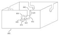
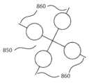
도 8a는 본 발명의 몇몇 실시예에 따른 예시적인 기계식 래버린스 구조를 도시한다;
도 8b는 본 발명의 몇몇 실시예에 따른 기계식 래버린스 구조와 상호 작용하기 위한 돌출부들을 갖는 예시적인 비행 기계를 도시한다;
도 9는 본 발명의 몇몇 실시예에 따른 두 개의 영역 및 전이 영역을 갖는 기계식 구조를 도시한다;
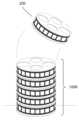
도 10a는 본 발명의 몇몇 실시예에 따른 예시적인 비행 기계들의 스택을 도시한다;
도 10b는 본 발명의 몇몇 실시예에 따른 비행 기계의 분해 조립도를 도시한다; 그리고
도 11은 본 발명의 몇몇 실시예에 따른 예시적인 통신 아키텍처의 블록도를 도시한다.Embodiments are illustrated by way of example and not limitation in the drawings of the accompanying drawings, wherein like reference numerals represent similar elements and wherein:
FIG. 1a illustrates a base of a charging container according to some embodiments of the present invention; embodiments are illustrated by way of example and not limitation in the drawings of the accompanying drawings, wherein like reference numerals represent similar elements, and wherein:
FIG. 1a illustrates a base of a charging container according to some embodiments of the present invention;
FIG. 1b illustrates a lid of a charging container according to some embodiments of the present invention;
FIG. 1c illustrates a filling container including a single base and a single lid according to some embodiments of the present invention;
FIG. 1d illustrates an integrated embodiment of an integrated charging container comprising multiple bases and lids according to some embodiments of the present invention;
FIG. 2a illustrates a side view of four representative embodiments for sandwiching flying machines between charging plates according to some embodiments of the present invention;
FIG. 2b illustrates an exemplary flying machine according to some embodiments of the present invention;
FIG. 2c illustrates an exemplary flying machine and charging plate according to some embodiments of the present invention;
FIG. 2d illustrates an exemplary flying machine and according to some embodiments of the present invention;
FIG. 3 illustrates an alternative system for charging and transporting flying machines according to some embodiments of the present invention;
FIG. 4 illustrates a block diagram of exemplary electrical components of a charging container according to some embodiments of the present invention;
FIG. 5 illustrates a block diagram of exemplary electrical components of a charging station and a flying machine according to some embodiments of the present invention;
FIG. 6 illustrates a block diagram of a charging module and its interconnection with two charging stations according to some embodiments of the present invention;
FIG. 7 illustrates exemplary flying machines suspended from cables according to some embodiments of the present invention;
FIG. 8a illustrates an exemplary mechanical labyrinth structure according to some embodiments of the present invention;
FIG. 8b illustrates an exemplary flying machine having protrusions for interacting with a mechanical labyrinth structure according to some embodiments of the present invention;
FIG. 9 illustrates a mechanical structure having two regions and a transition region according to some embodiments of the present invention;
FIG. 10a illustrates a stack of exemplary flying machines according to some embodiments of the present invention;
FIG. 10b illustrates an exploded assembly view of a flying machine according to some embodiments of the present invention; and
FIG. 11 illustrates a block diagram of an exemplary communication architecture according to some embodiments of the present invention.
본 발명에 따라, 비행 기계들을 수납, 충전 및 작동하기 위한 현재 시스템들의 한계점들이 감소되거나 제거되었다. 또한, 본 발명은 현재 시스템들에 비해 다양한 기술적 이점을 제공한다.According to the present invention, the limitations of current systems for storing, charging and operating flying machines are reduced or eliminated. In addition, the present invention provides various technical advantages over current systems.
일부 실시예에서, 충전 컨테이너 시스템들 및 방법들은 다수의 비행 기계의 통합된 충전 및 운반을 제공한다. 충전 컨테이너는 다음과 같은 방식으로 사용될 수 있다. 하나 이상의 비행 기계가 충전 스테이션 상에 배치된다. 이는 수동 또는 자동으로 달성될 수 있다(예를 들어, 충전 컨테이너 상에 비행 기계들을 자율적으로 착륙시킴으로써). 원하는 수의 비행 기계가 충전 컨테이너 상에 위치되면, 클램핑 메커니즘을 사용하여 비행 기계들의 위치들을 컨테이너에 기계식으로 고정한다. 전기 회로는 충전 스테이션들(예를 들어, 충전판, 충전 막대, 전도성 물질로 코팅된 자석들 등) 상의 충전 단자들을 비행 기계 상의 충전 커넥터들(예를 들어, 비행 기계의 케이지 상의 전도성 물질, 비행 기계 본체 상의 전도성 물질, 전도성 리프 스프링들, 전도성 핀들, 전도성 물질로 코팅된 자석들 등)에 연결함으로써 동시에 닫힐 수 있다. 이는 예를 들어, 클램핑 메커니즘이 (예를 들어, 상측 충전판과 하측 충전판 사이에 비행 기계를 끼움으로써) 비행 기계들을 두 개의 충전판에 밀어 대도록 컨테이너 및 그것의 구성요소들을 구성 및 배열시킴으로써 달성될 수 있다. 다른 예로서, 이는 클램핑 메커니즘이 비행 기계들을 제1 및 제2 충전 로드들 사이에 클램핑하도록 컨테이너 및 그것의 구성요소들을 구성 및 배열시킴으로써 달성될 수 있다. 추가 예로서, 전기 회로는 비행 기계가 충전 스테이션 상에 위치되자마자 추가적인 클램핑 동작 없이 닫힐 수 있다. 이러한 예에서, 연결은 예를 들어, 비행 기계 본체 상에 위치된 전도성 리프 스프링들이 비행 기계 상에 작용하는 중력에 의해 충전 스테이션의 충전판 상에 가압될 때, 중력에 의해 보조될 수 있다.In some embodiments, the charging container systems and methods provide for integrated charging and transport of multiple flying machines. The charging container may be used in the following manner: One or more flying machines are placed on a charging station. This may be accomplished manually or automatically (e.g., by autonomously landing the flying machines on the charging container). Once the desired number of flying machines are placed on the charging container, the positions of the flying machines are mechanically secured in the container using a clamping mechanism. The electrical circuit may be closed simultaneously by connecting charging terminals on the charging stations (e.g., charging plates, charging rods, magnets coated with a conductive material, etc.) to charging connectors on the flying machine (e.g., conductive material on the cage of the flying machine, conductive material on the body of the flying machine, conductive leaf springs, conductive pins, magnets coated with a conductive material, etc.). This may be accomplished, for example, by configuring and arranging the container and its components such that the clamping mechanism pushes the flying machines against the two charging plates (e.g., by sandwiching the flying machines between the upper and lower charging plates). As another example, this may be accomplished by configuring and arranging the container and its components such that the clamping mechanism clamps the flying machine between the first and second charging rods. As a further example, the electrical circuit may be closed without additional clamping action as soon as the flying machine is positioned on the charging station. In such an example, the connection may be assisted by gravity, for example, when conductive leaf springs positioned on the flying machine body are pressed against the charging plate of the charging station by gravity acting on the flying machine.
일부 실시예에서, 전기 회로는 비행 기계들을 충전할 수 있게 한다. 이는 충전 모듈을 제1 충전 단자, 제1 비행 기계 커넥터, 비행 기계 배터리, 제2 비행 기계 커넥터, 제2 충전 단자를 통해 다시 충전 모듈에 연결함으로써 달성된다. 일부 실시예에서, 회로는 (예를 들어, 비행 기계 커넥터들과 비행 기계 배터리 사이에) 비행 기계 상에 물리적으로 위치되고 배터리의 충전 프로세스를 모니터링 및 제어하는 충전 제어 회로를 포함할 수 있다. 충전 제어 회로는 예를 들어, 배터리 밸런싱을 수행할 수 있고, 충전 상태(state of charge : SOC) 또는 잔여 유효 수명(remaining useful life : RUL) 추정과 같은 모니터링 프로세스들을 수행할 수 있다.In some embodiments, the electrical circuit enables charging of the flying machines. This is accomplished by connecting the charging module back to the charging module via the first charging terminal, the first flying machine connector, the flying machine battery, the second flying machine connector, and the second charging terminal. In some embodiments, the circuit can include a charge control circuit that is physically located on the flying machine (e.g., between the flying machine connectors and the flying machine battery) and monitors and controls the charging process of the battery. The charge control circuit can, for example, perform battery balancing and perform monitoring processes such as estimating state of charge (SOC) or remaining useful life (RUL).
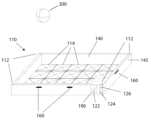
본 발명의 몇몇 실시예에 따라 도 1a는 충전 컨테이너의 베이스(110)를 도시하고 도 1b는 충전 컨테이너의 뚜껑(150)을 도시한다. 베이스(110)는 그 표면 상에 배치된 비행 기계(예를 들어, 비행 기계(200))와 전기 접속을 구축하도록 구성 및 배열된 전도성 물질을 포함하는 충전판(114)을 포함한다. 비행 기계(200)는 단순화를 위해 원형 케이지로 도시되어 있음이 이해될 것이다. 비행 기계(200)는 임의의 적합한 형상 및 크기일 수 있다. 충전판(114)은 각각 비행 기계를 수용하고 충전할 수 있는 다수의 충전 스테이션을 포함할 수 있다. 일부 실시예에서, 도 1a의 판(114) 상에 도시된 각각의 정사각형은 충전 스테이션일 수 있다. 일부 실시예에서, 충전판(114)은 각각의 대전 스테이션을 위한 별도의 충전 단자들을 포함할 수 있다.According to some embodiments of the present invention, FIG. 1A illustrates a base (110) of a charging container and FIG. 1B illustrates a lid (150) of the charging container. The base (110) includes a charging plate (114) comprising a conductive material configured and arranged to establish an electrical connection with a flying machine (e.g., a flying machine (200)) disposed on a surface thereof. It will be appreciated that the flying machine (200) is illustrated as a circular cage for simplicity. The flying machine (200) may be of any suitable shape and size. The charging plate (114) may include a plurality of charging stations, each of which may accommodate and charge the flying machine. In some embodiments, each of the squares illustrated on the plate (114) of FIG. 1A may be a charging station. In some embodiments, the charging plate (114) may include separate charging terminals for each charging station.
충전판(114)은 전원 소켓(122), 온/오프 전원 스위치(124) 및 상태 LED들(126)에 전기적으로 연결된 충전 모듈(190)에 전기적으로 연결된다. 전원 소켓(122)은 외부 전원 케이블(미도시)을 통해 충전 모듈(190)에 전력을 공급한다. 전원 스위치(124)는 사용자로 하여금 전원 연결을 차단할 수 있게 한다. 상태 LED들(126)은 충전 컨테이너의 전기적 상태를 사용자에게 알려준다. 예를 들어, LED들(126)은 충전 모듈(190)에 전력이 공급되고 있는지 여부를 나타낼 수 있다. 다른 예로서, LED들(126)은 비행 기계가 충전 스테이션에 전기적으로 연결되어 있는지 여부, 비행 기계가 충전 중인지 여부 그리고/또는 비행 기계가 완전히 충전되었는지 여부와 같은 각 충전 스테이션에서의 충전 상태를 나타낼 수 있다.The charging plate (114) is electrically connected to a charging module (190) which is electrically connected to a power socket (122), an on/off power switch (124), and status LEDs (126). The power socket (122) supplies power to the charging module (190) via an external power cable (not shown). The power switch (124) allows a user to disconnect the power connection. The status LEDs (126) inform the user of the electrical status of the charging container. For example, the LEDs (126) may indicate whether power is being supplied to the charging module (190). As another example, the LEDs (126) may indicate the charging status at each charging station, such as whether the flying machine is electrically connected to the charging station, whether the flying machine is charging, and/or whether the flying machine is fully charged.
일부 실시예에서, 보다 진보된 인터페이스들이 충전 컨테이너의 일부로서 제공될 수 있다. 예를 들어, 사용자가 충전 컨테이너의 동작을 제어할 수 있게 하기 위해 통합된 LCD 디스플레이 또는 터치스크린이 제공될 수 있다. 다른 예로는, Wi-Fi 및 이더넷과 같은 추가 연결이 제공될 수 있다.In some embodiments, more advanced interfaces may be provided as part of the charging container. For example, an integrated LCD display or touchscreen may be provided to allow a user to control the operation of the charging container. In other examples, additional connectivity such as Wi-Fi and Ethernet may be provided.
베이스(110)는 하나 이상의 내부 커넥터(112)를 포함할 수 있다. 각각의 내부 커넥터(112)는 뚜껑이 베이스(110) 상에(예컨대, 도 1c 또는 도 1d에서와 같이) 또는 추가 베이스가 베이스(110) 상에 위치될 때(예컨대, 도 1d에서와 같이) 추가 베이스 상에 위치될 때 뚜껑 상의 대응하는 내부 커넥터(예컨대, 도 1b의 내부 커넥터(152))에 전기적으로 결합되도록 구성 및 배치될 수 있다. 내부 커넥터들(112 및 152) 사이의 전기적 결합은 임의의 적절한 커넥터(예컨대, 스프링 장착된 커넥터 또는 임의의 다른 적합한 전기 커넥터)를 사용하여 달성될 수 있다.The base (110) may include one or more internal connectors (112). Each internal connector (112) may be configured and positioned to electrically couple to a corresponding internal connector on the lid (e.g., internal connector (152) of FIG. 1B) when the lid is positioned on the base (110) (e.g., as in FIG. 1C or FIG. 1D) or when an additional base is positioned on the base (110) (e.g., as in FIG. 1D). Electrical coupling between the internal connectors (112 and 152) may be accomplished using any suitable connector (e.g., a spring loaded connector or any other suitable electrical connector).
도 1a의 베이스(110) 및 도 1b의 뚜껑(150) 각각은 내벽(140)을 포함한다. 내벽(140)은 충전판(예를 들어, 도 1a의 충전판(114) 및 도 1b의 충전판(154))으로서 사용될 수 있고, 비 전도성 재료 또는 이들의 조합으로 만들어질 수 있다. 도 1a의 베이스(110) 및 도 1b의 뚜껑(150) 각각은 외벽(142)을 포함한다. 외벽(142)은 베이스(110) 및 뚜껑(150)을 함께 고정시키기 위한 하나 이상의 클램핑 메커니즘(160)(예를 들어, 걸쇠, 래치 등)을 구비할 수 있다. 외벽(142)은 또한 용이한 운반을 위해 하나 이상의 핸들(미도시)을 구비할 수 있다.Each of the base (110) of FIG. 1A and the lid (150) of FIG. 1B includes an inner wall (140). The inner wall (140) can be used as a charging plate (e.g., the charging plate (114) of FIG. 1A and the charging plate (154) of FIG. 1B) and can be made of a non-conductive material or a combination thereof. Each of the base (110) of FIG. 1A and the lid (150) of FIG. 1B includes an outer wall (142). The outer wall (142) can have one or more clamping mechanisms (160) (e.g., a latch, a catch, etc.) for securing the base (110) and the lid (150) together. The outer wall (142) can also have one or more handles (not shown) for easy carrying.
베이스(110)는 뚜껑(150) 또는 다른 베이스에 기계적 지지를 제공한다. 비행 기계들이 자동으로 충전판 상에 놓여지면, 비행 기계의 착륙 또는 도킹 조종 중에 운항을 돕기 위해 베이스(110)가 사용될 수 있다. 이는 (1) 베이스(110) 상의 명확한 위치들에 명확한 피처들(예를 들어, 마킹들, 위치 LED들, 발광체들, 무선 주파수(RF) 방사체들)을 통합시킴으로써, (2) 비행 기계들에 이러한 피처들 검출에 적합한 센서들(예를 들어, 비전 센서들, RF 센서들)을 구비시킴으로써, 그리고 (3) 명확한 피처들에 관한 비행 기계의 현재 위치, 비행 기계의 원하는 착륙 또는 도킹 위치(예를 들어, 충전 스테이션), 그리고 원하는 착륙 또는 도킹 위치에 관한 명확한 피처들의 기지 위치를 나타내는 센서 판독치들에 따라 비행 기계 상에서 착륙 또는 도킹 시퀀스를 실행함으로써 달성될 수 있다.The base (110) provides mechanical support to the lid (150) or other base. Once the flying machine is autonomously placed on the charging plate, the base (110) can be used to assist in the navigation of the flying machine during landing or docking maneuvers. This can be accomplished by (1) incorporating distinct features (e.g., markings, location LEDs, luminescent elements, radio frequency (RF) emitters) at distinct locations on the base (110), (2) equipping the flying machine with sensors suitable for detecting such features (e.g., vision sensors, RF sensors), and (3) executing a landing or docking sequence on the flying machine based on sensor readings indicating the current position of the flying machine relative to the distinct features, a desired landing or docking location for the flying machine (e.g., a charging station), and a known location of the distinct features relative to the desired landing or docking location.
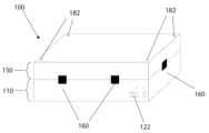
도 1c는 단일 베이스(110) 및 단일 뚜껑(150)을 포함한 충전 컨테이너(100)를 도시한다. 도시된 바와 같이, 충전 컨테이너(100)에는 충전 및/또는 운반을 위해 베이스 및 뚜껑을 연결하는 클램핑 메커니즘(160)이 구비된다.Figure 1c illustrates a filling container (100) including a single base (110) and a single lid (150). As illustrated, the filling container (100) is provided with a clamping mechanism (160) that connects the base and lid for filling and/or transport.
도 1c의 뚜껑(150)은 또한 하나 이상의 외부 커넥터(182)를 포함할 수도 있다. 외부 커넥터들(182)은 다수의 컨테이너가 적층될 때 다른 충전 컨테이너 상의 대응하는 외부 커넥터(182)에 연결되도록 구성 및 배열될 수 있다. 외부 커넥터들 사이의 전기적 결합은 예를 들어, 스프링 장착된 연결 플러그를 사용하여 달성될 수 있다. 외부 커넥터들은 단일 전원 소켓(122)을 통해 다수의 충전 컨테이너에 전력을 공급할 수 있다. 외부 커넥터는 다른 적합한 외부 커넥터와 접촉할 때만 전원이 공급됨을 보장하는 안전 회로를 포함할 수 있다.The lid (150) of FIG. 1c may also include one or more external connectors (182). The external connectors (182) may be configured and arranged to connect to corresponding external connectors (182) on other charging containers when multiple containers are stacked. Electrical coupling between the external connectors may be accomplished, for example, using spring-loaded connecting plugs. The external connectors may provide power to the multiple charging containers through a single power socket (122). The external connector may include safety circuitry to ensure that power is supplied only when in contact with another suitable external connector.
도 1c의 충전 컨테이너(100)는 개별적으로 또는 스택에서의 추가 충전 컨테이너들과 조합하여 사용될 수 있다. 도 1c의 충전 컨테이너(100)를 추가 충전 컨테이너들과 적층되도록 의도할 때, 추가 클램핑 메커니즘들이 충전 컨테이너들을 함께 고정하는데 사용될 수 있다. 또한 하나의 충전 컨테이너의 충전 모듈이 추가 충전 컨테이너들의 비행 기계들을 충전하는 데 사용될 수 있음이 이해될 것이다. 일부 실시예에서, 추가 충전 컨테이너들에는 전원 소켓 및 온/오프 전원 스위치가 생략될 수 있다.The charging container (100) of FIG. 1c may be used individually or in combination with additional charging containers in a stack. When the charging container (100) of FIG. 1c is intended to be stacked with additional charging containers, additional clamping mechanisms may be used to secure the charging containers together. It will also be appreciated that the charging module of one charging container may be used to charge the flight machines of the additional charging containers. In some embodiments, the additional charging containers may omit the power socket and the on/off power switch.
도 1d는 본 발명의 몇몇 실시예에 따른 통합 충전 컨테이너(100)가 다수의 베이스(110) 및 뚜껑(150)을 포함하는 통합 실시예를 도시한다.FIG. 1d illustrates an integrated embodiment of an integrated charging container (100) comprising a plurality of bases (110) and lids (150) according to some embodiments of the present invention.
통합 충전 컨테이너(100)는 통합 충전 컨테이너의 상하로서 사용되는 두 개의 단부 덮개(150)로 구성된다. 하부 덮개에는 용이한 운반을 위해 휠들(170)이 장착된다. 이러한 실시예에서, 충전 모듈(190), 전원 소켓(122), 전원 스위치(124) 및 상태 LED들(126)이 상부 덮개(150)에 포함된다. 이러한 실시예에서, 네 개의 베이스(110) 각각은 두 개의 충전판(114 및 154)을 포함하도록 구성 및 배열된다. 비행 기계들(200)은 하측 베이스(110)의 제1 충전판(114)과 상측 베이스(110)의 제2 충전판(154) 사이에 끼워진다. 통합 충전 컨테이너(100)의 상이한 층들은 클램핑 메커니즘들(160)을 사용하여 함께 연결될 수 있다.The integrated charging container (100) is comprised of two end covers (150) that serve as the upper and lower portions of the integrated charging container. The lower cover is equipped with wheels (170) for easy transport. In this embodiment, a charging module (190), a power socket (122), a power switch (124), and status LEDs (126) are included in the upper cover (150). In this embodiment, each of the four bases (110) is configured and arranged to include two charging plates (114 and 154). The flying machines (200) are sandwiched between the first charging plate (114) of the lower base (110) and the second charging plate (154) of the upper base (110). The different layers of the integrated charging container (100) can be connected together using clamping mechanisms (160).
이러한 실시예는 다수의 비행 기계(200)를 특히 간편하게 충전, 수납 또는 운반할 수 있게 한다. 이러한 대표적인 실시예는 변형이 가능하다. 예를 들어, 충전 컨테이너들은 서랍들로서 만들어질 수 있다. 다른 예로서, 내부 커넥터들은 연결 플러그들 또는 연결 케이블들로서 만들어질 수 있다.This embodiment allows for a particularly easy charging, storage or transport of a plurality of flying machines (200). This representative embodiment is subject to modification. For example, the charging containers may be made as drawers. As another example, the internal connectors may be made as connecting plugs or connecting cables.
도 2a는 본 발명의 몇몇 실시예에 따른 충전판들(114 및 154) 사이에 비행 기계들을 끼우기 위한 네 개의 대표적인 실시예의 측면도를 도시한다. 끼움은 충전판들(114 및 154) 사이에 힘(210)을 가함으로써 달성된다. 이는 클램핑 메커니즘을 사용함으로써 달성될 수 있다.FIG. 2a illustrates a side view of four representative embodiments for fitting flying machines between charging plates (114 and 154) according to some embodiments of the present invention. Fitting is accomplished by applying a force (210) between the charging plates (114 and 154). This may be accomplished by using a clamping mechanism.
각각의 비행 기계(200)는 그 본체(220)에 연결된 적어도 두 개의 커넥터(214 및 254)를 포함한다. 커넥터들(214 및 254)은 충전판들(114 및 154)과 전기 접촉할 수 있게 한다. 이는 비행 기계들의 배터리들 및 작동 매개 변수들(예를 들어, 최소 충전 시간, 배터리 크기)에 의해 요구되는 충전 전압 및 암페어에 따라 적절한 전도도를 갖는 물질들을 선택하고, 비행 기계들의 탑재 하중에 따라 적절한 무게를 선택하고, 비행 기계들의 동역학적 속성뿐만 아니라 공기 역학적 속성에 따라 적절한 형상을 선택하며, 비행 기계들 및 충전판들의 형상 및 표면 속성들에 따라 적절한 연결 속성들(예를 들어, 스프링 장착된 커넥터들, 자기 커넥터들)을 선택함으로써 달성될 수 있다. 전기 접촉은 또한 클램핑의 결과로서의 힘(210)에 따른 잠재적인 구조적 변형을 고려함으로써 달성될 수 있다.Each flying machine (200) includes at least two connectors (214 and 254) connected to its body (220). The connectors (214 and 254) enable electrical contact with the charging plates (114 and 154). This can be accomplished by selecting materials having appropriate conductivity based on the charging voltage and amperage required by the batteries of the flying machines and the operating parameters (e.g., minimum charging time, battery size), selecting an appropriate weight based on the payload of the flying machines, selecting an appropriate shape based on the aerodynamic properties as well as the dynamic properties of the flying machines, and selecting appropriate connection properties (e.g., spring loaded connectors, magnetic connectors) based on the shape and surface properties of the flying machines and the charging plates. Electrical contact can also be accomplished by considering potential structural deformation due to the force (210) as a result of clamping.
커넥터들(214 및 254)은 동시에 비행 기계들(200)을 보관 및 운반을 위한 위치로 고정시키는데 사용될 수 있다. 이는 (1) 판들(114 및 154) 사이에 끼워진 비행 기계들(200)에 힘을 가하는 클램핑 메커니즘을 사용함으로써; (2) 비행 기계(200)가 커넥터들(214 및 254)과 충전판들(114 및 154) 사이의 마찰에 따라 판들(114 및 154) 사이에 끼워질 때 그것이 움직이지 않도록 커넥터들(214 및 254)을 구성 및 배열시킴으로써; 그리고 (3) 판들(114 및 154) 및 비행 기계 본체들(220)을 구조적 손상 없이 끼울 수 있게 하도록 구성 및 배열시킴으로써 달성될 수 있다.The connectors (214 and 254) may be used to simultaneously secure the flying machines (200) in a position for storage and transport. This may be accomplished by (1) using a clamping mechanism that applies force to the flying machines (200) sandwiched between the plates (114 and 154); (2) configuring and arranging the connectors (214 and 254) so that the flying machine (200) does not move when sandwiched between the plates (114 and 154) due to friction between the connectors (214 and 254) and the charging plates (114 and 154); and (3) configuring and arranging the plates (114 and 154) and the flying machine bodies (220) so as to be sandwiched without structural damage.
일부 실시예에서, 충전 컨테이너는 기계식 가이드들을 포함할 수 있다. 예를 들어, 충전판(114)은 기계식 가이드들로서 기능하는 오목부들을 내재할 수 있다. 그러한 가이드들은 비행 기계들을 박스에 넣을 때 그것들을 특정 위치들 또는 특정 방향들로 가이드하기 위해 사용될 수 있다. 이러한 가이딩 프로세스는 통상적으로 수동적이다, 즉, 비행 기계들은 그것들이 박스(100)에 넣어질 때 위치/방향으로 미끄러져 들어간다. 이러한 프로세스를 쉽게 하기 위해 다양한 고안을 사용할 수 있다. 예들로 비행 기계들(200)과 충전 컨테이너 사이의 접점들에 저 마찰 물질들을 사용하는 것(예컨대, 광택 금속); 비행 기계들의 본체들의 형상을 개조하는 것; 비행 기계들의 케이지들 또는 슈라우드들의 형상을 개조하는 것(예컨대, 구형 케이지를 사용하는 것); 베이스(110)를 흔드는 것(예를 들어, 수동 또는 자동으로(예컨대, 진동 모터를 사용하여)); 비행 기계(200)가 전용 착륙 조종(예컨대, 도킹 조종)을 수행하게 하는 것; 비행 기계(200) 또는 충전 컨테이너(100) 상에 자석들을 사용하는 것(예컨대, 영구적으로 자화된 물질 또는 전자석들) 또는 충전 컨테이너(100) 또는 그것의 베이스들(110)을 비스듬하게 위치시키는 것(예컨대, 컨테이너들에 바닥 상에 놓았을 때 비스듬하게 받쳐줄 수 있게 하는 받침대를 장착하거나 충전 박스에 각진 베이스를 장착하는 것) 또는 기타(예를 들어, 충전 컨테이너에 비행 기계들을 수집, 분류 또는 배치하기 위한 미끄럼판(chute) 또는 누두(funnel)로서 작용하는 널빤지(landing board)(미도시)를 부가하는 것)를 포함한다. 기계식 가이드들의 예들은 함입부들, 노치들, 누두들, 레일들 또는 홈들을 포함한다.In some embodiments, the charging container may include mechanical guides. For example, the charging plate (114) may include recesses that function as mechanical guides. Such guides may be used to guide the flying machines into specific positions or orientations when they are placed into the box. This guiding process is typically manual, i.e., the flying machines slide into positions/orientations when they are placed into the box (100). Various designs may be used to facilitate this process. Examples include using low-friction materials at the contact points between the flying machines (200) and the charging container (e.g., polished metal); modifying the shape of the bodies of the flying machines; modifying the shape of the cages or shrouds of the flying machines (e.g., using a spherical cage); shaking the base (110) (e.g., manually or automatically (e.g., using a vibrating motor)); causing the flying machine (200) to perform dedicated landing maneuvers (e.g., docking maneuvers); Using magnets (e.g., permanently magnetized material or electromagnets) on the flying machine (200) or the charging container (100) or positioning the charging container (100) or its bases (110) at an angle (e.g., mounting pedestals on the containers to allow them to rest at an angle when placed on the floor or mounting an angled base on the charging box) or others (e.g., adding a landing board (not shown) to act as a chute or funnel for collecting, sorting or placing the flying machines on the charging container). Examples of mechanical guides include recesses, notches, grooves, rails or grooves.
가이드들은 또한 비행 기계들(200)을 고정 또는 운반할 위치에 배치하는데 사용될 수 있다. 이는 비행 기계들의 형상과 일치하도록 가이드들을 구성 및 배열시킴으로써 달성될 수 있다. 도 1a의 대표적인 실시예에서, 역 피라미드 형상들의 기계식 가이드들은 그 크기들이 비행 기계들의 구형 케이지의 형상과 일치하도록 만들어져 사용된다.The guides may also be used to position the flying machines (200) in a position to be secured or transported. This may be accomplished by configuring and arranging the guides to match the shape of the flying machines. In the exemplary embodiment of Fig. 1a, mechanical guides of inverted pyramid shapes are used whose dimensions are made to match the shape of the spherical cage of the flying machines.
또한 가이드들을 사용하여 비행 기계들을 특정 패턴으로 배치할 수 있다. 예를 들어, 도 1a의 대표적인 실시예에 도시된 역 사각 피라미드들을 사용하여 비행 기계들을 격자 패턴으로 배열시킬 수 있다. 유사하게, 삼각 또는 육각 피라미드들을 사용하여 비행 기계들을 등각 또는 육각 격자로 배열시킬 수 있다.Guides can also be used to arrange the flying machines in a specific pattern. For example, the inverse square pyramids illustrated in the representative embodiment of Fig. 1a can be used to arrange the flying machines in a grid pattern. Similarly, triangular or hexagonal pyramids can be used to arrange the flying machines in an equiangular or hexagonal grid.
유사하게, 많은 다른 모자이크 세공 또는 패턴이 달성될 수 있다.Similarly, many other mosaic finishes or patterns can be achieved.
배열들은 심미적인 이유들로(예를 들어, 비행 기계들을 조명 디스플레이의 일부로 사용할 때) 사용될 수 있다. 배열들은 충전 또는 운반을 위한 위치로 가이드할 수 있도록 사용될 수 있다. 이는 수동 조작이 거의 없거나 전혀 없는 많은 비행 기계를 가이드할 수 있도록 할 수 있다. 또한 배열들은 예를 들어 액추에이터의 자유로운 움직임을 허용하도록 구성 및 배열함으로써(예를 들어, 액추에이터의 움직임이 가이드들, 충전기들 및 다른 비행 기계들을 포함하여 장애물들에 의해 제한되지 않음을 기계적으로 보장함으로써), 자율 이륙 또는 착륙할 수 있게 하도록 사용될 수도 있다. 다른 예로서, 그것들은 동일한 컨테이너 상에서 계속 이륙 또는 착륙하는 다수의 비행 기계의 자유로운 공기 흐름/난류를 줄일 수 있게 하도록 구성 및 배열될 수 있다(예를 들어, 컨테이너에서의 그것들의 위치를 나타내는 데이터를 사용하여 그것들의 이륙 또는 착륙 순서를 결정함으로써 또는 에어 쿠션 생성을 줄이기 위해 컨테이너에 통풍관들, 통풍구들, 와이어 그리드들 또는 유로 가이드들을 장착함으로써). 다른 예로서, 배열들은 방향(예를 들어, 비행 기계의 요우)이 (예컨대, 기계식 가이드들 또는 센서들을 통해) 알려져 있음을 보장함으로써 이륙 조종을 더 신뢰할 수 있게 할 수 있다. 유사하게, 배열들을 루틴들을 교정할 수 있게 할 수 있다. 일부 실시예에서, 비행 기계들은 컨테이너에서의 그것들의 위치 및 방향을 육안으로 점검할 수 있게 하도록 마킹된다(예컨대, 그것들의 아암 중 하나 상에 색 코딩된 밴드로). 일부 실시예에서, 비행 기계들은 비행 기계 식별자를 컨테이너에 전달하도록 구성 및 배열된다. 일부 실시예에서, 컨테이너는 충전 스테이션 식별자를 해당 충전 스테이션의 비행 기계에 전달하도록 구성 및 배치된다.The arrays may be used for aesthetic reasons (e.g., when using the flying machines as part of a light display). The arrays may be used to guide them into position for charging or transport. This may allow for guiding many flying machines with little or no manual intervention. The arrays may also be used to allow for autonomous takeoff or landing, for example, by configuring and arranging them to allow free movement of the actuators (e.g., by mechanically ensuring that the movement of the actuators is not restricted by obstacles including the guides, chargers and other flying machines). As another example, they may be configured and arranged to reduce free airflow/turbulence of many flying machines taking off or landing continuously on the same container (e.g., by using data indicating their positions in the container to determine their takeoff or landing order, or by equipping the container with ducts, vents, wire grids or flow guides to reduce air cushion creation). As another example, the arrangements can make takeoff maneuvers more reliable by ensuring that the direction (e.g., the yaw of the flying machine) is known (e.g., via mechanical guides or sensors). Similarly, the arrangements can enable correcting routines. In some embodiments, the flying machines are marked (e.g., with a color-coded band on one of their arms) to allow for visual inspection of their position and orientation in the container. In some embodiments, the flying machines are configured and arranged to convey a flying machine identifier to the container. In some embodiments, the container is configured and arranged to convey a charging station identifier to the flying machine at that charging station.
또한 가이드들을 사용하여 비행 기계들을 전기 충전할 위치로 배치할 수 있다. 이는 올바른 양극 및 음극의 연결을 보장하는데 유용할 수 있다. 이는 스마트 충전기들을 사용할 때(예를 들어, 동시에 충전되는 비행 기계들의 수를 결정하기 위해) 또는 스마트 배터리들을 사용할 때(예를 들어, 배터리 관리 시스템을 구비한 배터리들), 추가 커넥터들(예를 들어, 배터리 조정, 배터리 밸런싱 또는 배터리 통신용)을 구비한 비행 기계들에 유용할 수 있다. 이는 가이드들, 비행 기계의 커넥터들 및 충전 단자들을 비행 기계의 커넥터들을 충전 단자들에 쉽게 정렬시키고 연결할 수 있게 하도록 구성 및 배열시킴으로써 달성될 수 있다. 이는 예를 들어, 블라인드 메이트 커넥터들(blind mate connectors)을 사용하여 달성될 수 있다. 추가 예들로서, 이는 또한 스프링 바이어싱되거나 스프링 장착된 또는 적어도 하나의 가이딩 표면을 포함하는 메이팅 커넥터들을 사용함으로써 달성될 수도 있다.Guides can also be used to position the flying machines into position for electrical charging. This can be useful for ensuring proper positive and negative connection. This can be useful when using smart chargers (e.g., to determine the number of flying machines to be charged simultaneously) or when using smart batteries (e.g., batteries with battery management systems) with flying machines having additional connectors (e.g., for battery regulation, battery balancing or battery communication). This can be accomplished by configuring and arranging the guides, the flying machine connectors and the charging terminals so that the flying machine connectors can be easily aligned and connected to the charging terminals. This can be accomplished, for example, by using blind mate connectors. As additional examples, this can also be accomplished by using mating connectors that are spring biased or spring loaded or that include at least one guiding surface.
가이드들은 또한 충전 회로들 사이에 전기 절연을 제공하는 데 사용될 수 있다. 이는 그것들에 절연체를 장착하거나 그것들을 비 전도성 물질로 제조함으로써 달성될 수 있다.The guides can also be used to provide electrical insulation between charging circuits. This can be accomplished by mounting an insulator on them or by manufacturing them from a non-conductive material.
일부 실시예에서, 커넥터들은 기계식 가이드들에 맞추기 위해 기계적으로 정합될 수 있다. 이는 비행 기계들과 박스 사이의 전기 접속을 향상시키거나, 운반 중 비행 기계들의 고정을 향상시키거나, 비행 기계들을 특정 위치들 또는 방향들로 가이드할 때 가이드들의 효율을 향상시키는데 유용할 수 있다. 이는, 메이팅될 때 사소한 정렬 오류를 허용하는 자정렬 피처들과 함께 본 발명에서 설명된 피처들을 커넥터들과 조합시킴으로써 달성될 수 있다. 예를 들어, 비행 기계 상의 대응하는 텅(tongue), 비드(bead), 볼트 또는 도그(dog)와 충전판 상의 홈 또는 슬롯이 사용될 수 있다.In some embodiments, the connectors may be mechanically mated to align with the mechanical guides. This may be useful for improving electrical connection between the flying machines and the box, improving fixation of the flying machines during transport, or improving the efficiency of the guides when guiding the flying machines to specific positions or orientations. This may be accomplished by combining the features described herein with self-aligning features that allow for minor misalignment when mating the connectors. For example, a corresponding tongue, bead, bolt or dog on the flying machine and a groove or slot on the charging plate may be used.
다시 도 1a 내지 도 1d를 참조하면, 클램핑 메커니즘(160)은 복수의 비행 기계 상에 동시에 힘을 가할 수 있다. 클램핑 메커니즘(160)은 또한 컨테이너 베이스(110)를 뚜껑(150) 또는 추가의 컨테이너에 기계적으로 연결할 수 있다. 그것은 명확한 기계력을 비행 기계(200)에 인가할 수 있다. 이는 탄성 요소들을 사용하여 달성될 수 있다. 예컨대, 충전판들은 포옴 또는 다른 탄성 재료에 의해 지지될 수 있거나 또는 비행 기계 커넥터들이 탄성 재료를 포함할 수 있다. 힘은 또한 클램핑 메커니즘들의 유형, 수 또는 배치, 또는 벽들(140) 또는 컨테이너 베이스(110)에 의해 제공되는 크기 또는 기계적 지지를 비행 기계들의 크기 또는 구조적 속성들에 맞춤으로써 조정될 수 있다. 대표적인 클램핑 메커니즘들은 레버 조작식 래치, 신속 클램프 파스너, 탄성 앵커, 스프링 래치 및 토글 클램프를 포함한다.Referring again to FIGS. 1A-1D , the clamping mechanism (160) can apply force to multiple flight machines simultaneously. The clamping mechanism (160) can also mechanically connect the container base (110) to the lid (150) or to an additional container. It can apply a specific mechanical force to the flight machine (200). This can be accomplished using elastomeric elements. For example, the filler plates can be supported by foam or other elastomeric material, or the flight machine connectors can include elastomeric material. The force can also be adjusted by adjusting the type, number, or arrangement of the clamping mechanisms, or the size or mechanical support provided by the walls (140) or the container base (110), to suit the size or structural properties of the flight machines. Exemplary clamping mechanisms include lever-operated latches, quick clamp fasteners, elastomeric anchors, spring latches, and toggle clamps.
도 2b는 본 발명의 몇몇 실시예에 따른 비행 기계(200)를 도시한다. 비행 기계(200)는 본체(220), 센서(260), 대응하는 프로펠러들(272)을 갖는 네 개의 액추에이터(270), 제어 모듈(280), 배터리(290) 및 두 개의 커넥터(예를 들어, 후크)(214 및 254)를 포함한다. 충전 회로(미도시)는 두 개의 커넥터(214 및 254) 각각을 배터리(290)에 전기적으로 연결한다.FIG. 2b illustrates a flying machine (200) according to some embodiments of the present invention. The flying machine (200) includes a body (220), a sensor (260), four actuators (270) having corresponding propellers (272), a control module (280), a battery (290), and two connectors (e.g., hooks) (214 and 254). A charging circuit (not shown) electrically connects each of the two connectors (214 and 254) to the battery (290).
도 2c는 본 발명의 몇몇 실시예에 따른 비행 기계(200) 및 충전판(114)을 도시한다. 비행 기계(200)는 본체(220), 센서(260), 대응하는 프로펠러들(272)을 갖는 네 개의 액추에이터(270), 제어 모듈(280), 배터리(290) 및 네 개의 커넥터(214)를 포함한다. 커넥터들과 충전판(114) 사이의 양호한 전기 접속을 보장하기 위해 하나 이상의 커넥터(214) (예를 들어, 하나, 둘, 셋 또는 모두 네 개)가 자석들(예를 들어, 영구 자석 또는 전자석)을 포함할 수 있다. 일부 실시예에서, 자석들은 또한 비행 기계(200)를 충전판(114)에 고정하기에 충분한 강도를 가질 수 있다. 회로(미도시)는 두 개 이상의 커넥터(214)를 비행 기계(200)의 구성요소들(예를 들어, 배터리(290))에 전기적으로 연결한다. 도 2c에 도시된 바와 같이, 충전판(114)은 섹션들(114.1-5)을 포함한다. 섹션(114.5)은 판(114)의 비전도성 섹션이고 그것은 섹션들(114.1-4)을 전기적으로 절연시킨다. 각 섹션들(114.1-4)은 주름진 형상 또는 다른 형상으로 비행 기계(200)를 원하는 위치 및 방향으로 위치시키는 것을 도울 수 있다. 일부 실시예에서, 하나 이상의 섹션(114.1-5)은 비행 기계(200)를 원하는 위치 및 방향으로 가이딩하거나 섹션들(114.1-4)과 하나 이상의 커넥터(214) 사이의 양호한 전기 접속을 보장하는 것을 돕기 위해 자석들(예를 들어, 영구 자석 또는 전자석)을 포함할 수 있다. 일부 실시예들에서, 섹션들(114.1-4) 각각은 충전 단자 또는 통신 인터페이스로서 사용될 수 있다. 도 2c에 도시된 전체 충전판(114)은 단일 충전 스테이션에 대응할 수 있다.FIG. 2C illustrates a flying machine (200) and a charging plate (114) according to some embodiments of the present invention. The flying machine (200) includes a body (220), a sensor (260), four actuators (270) having corresponding propellers (272), a control module (280), a battery (290), and four connectors (214). One or more of the connectors (214) (e.g., one, two, three, or all four) may include magnets (e.g., permanent magnets or electromagnets) to ensure a good electrical connection between the connectors and the charging plate (114). In some embodiments, the magnets may also be of sufficient strength to secure the flying machine (200) to the charging plate (114). Circuitry (not shown) electrically connects the two or more connectors (214) to components of the flying machine (200) (e.g., the battery (290)). As illustrated in FIG. 2c, the charging plate (114) includes sections (114.1-5). Section (114.5) is a non-conductive section of the plate (114) that electrically insulates the sections (114.1-4). Each of the sections (114.1-4) may have a corrugated shape or other shape to assist in positioning the flight machine (200) in a desired position and orientation. In some embodiments, one or more of the sections (114.1-5) may include magnets (e.g., permanent magnets or electromagnets) to assist in guiding the flight machine (200) in a desired position and orientation or to ensure a good electrical connection between the sections (114.1-4) and one or more connectors (214). In some embodiments, each of the sections (114.1-4) may be used as a charging terminal or a communication interface. The entire charging plate (114) illustrated in FIG. 2c may correspond to a single charging station.
도 2d는 본 발명의 일부 실시예에 따른 비행 기계(200) 및 충전 스테이션의 다른 예를 도시한다. 비행 기계(200)는 비행 기계(200)가 충전 스테이션 상에 놓일 때, 각각 충전판들(114.1 및 114.2)과 접촉을 이루는 두 개의 충전 커넥터(214.1 및 214.2)를 포함한다. 비행 기계(200)는 비행 기계가 충전 스테이션 상에 놓일 때 통신판(115)과 접촉을 이루는 통신 커넥터(215)를 더 포함한다. 이러한 예에서, 비행 기계 커넥터들(214.1, 214.2 및 215)은 비행 기계(200) 상에 작용하는 중력을 받아 편향됨으로써 대응하는 충전판들(114.1 및 114.2) 및 통신판(115)에 전기 접속부를 제공하는 리프 스프링 접점들을 추가적인 클램핑 힘이 필요하지 않도록 적절한 치수로 만들어진다. 충전판은 비행 기계(200)가 충전 스테이션 상에 놓일 때 (예를 들어, 충전 컨테이너(100)의 운분 중에) 비행 기계(200)의 수평 움직임을 제한하는 가이드들(116.1-3)을 더 포함한다. 가이드들(116.1 및 116.2)은 충전 스테이션상의 정확한 비행 기계(200)의 방향만을 허용하기 위해, 각각 비행 기계(200)상의 피처들(220.1 및 220.2)과 매칭하도록 형성되며, 이는 전기 접속부들의 극성이 맞는 것을 보장하도록 도울 수 있다. 예시된 바와 같이, 피처들(220.1 및 220.2)은 그것들 각각의 로터 아암들 상에 비행 기계(200)의 중심으로부터 서로 다른 거리들에 위치된다. 이러한 서로 다른 거리들은 가이드들(116.1 및 116.2) 내의 대응하는 오목부들의 위치들과 매칭하며 그에 따라 비행 기계(200)는 단지 한 방향으로만 충전 스테이션 상에 맞게 될 것이다. 예시된 피처들 및 가이드들은 단지 예시적인 것이며 임의의 적합한 피처들 및 가이드들이 충전 스테이션 상의 적절한 위치 및 방향으로 비행 기계(200)를 위치시키는 것을 돕기 위해 사용될 수 있음이 이해될 것이다.FIG. 2d illustrates another example of a flying machine (200) and a charging station according to some embodiments of the present invention. The flying machine (200) includes two charging connectors (214.1 and 214.2) that make contact with charging plates (114.1 and 114.2) respectively when the flying machine (200) is placed on the charging station. The flying machine (200) further includes a communication connector (215) that makes contact with a communication plate (115) when the flying machine is placed on the charging station. In this example, the flying machine connectors (214.1, 214.2 and 215) are dimensioned so that no additional clamping force is required to provide leaf spring contacts that deflect under the force of gravity acting on the flying machine (200) to provide electrical connections to the corresponding charging plates (114.1 and 114.2) and the communication plate (115). The charging plate further includes guides (116.1-3) that limit the horizontal movement of the flying machine (200) when the flying machine (200) is placed on the charging station (e.g., during transportation of the charging container (100)). The guides (116.1 and 116.2) are formed to match features (220.1 and 220.2) on the flying machine (200), respectively, to allow only the correct orientation of the flying machine (200) on the charging station, which may help ensure that the polarity of the electrical connections is correct. As illustrated, the features (220.1 and 220.2) are positioned at different distances from the center of the flying machine (200) on their respective rotor arms. These different distances match the locations of corresponding recesses within the guides (116.1 and 116.2) such that the flying machine (200) will only fit on the charging station in one orientation. It will be appreciated that the illustrated features and guides are merely exemplary and that any suitable features and guides may be used to assist in positioning the flying machine (200) in an appropriate location and orientation on the charging station.
도 3은 본 발명의 몇몇 실시예에 따른 복수의 비행 기계를 충전 및 운반하기 위한 대안적인 시스템을 도시한다. 도 3의 시스템은 충전 컨테이너의 단자들로서 두 개의 충전 막대(314 및 354)를 포함한다.Figure 3 illustrates an alternative system for charging and transporting a plurality of flying machines according to some embodiments of the present invention. The system of Figure 3 includes two charging rods (314 and 354) as terminals of the charging container.
충전 막대들(314 및 354)은 또한 지지 구조체들로서도 작용한다. 충전 막대들(314 및 354)은 다음과 같은 방식으로 사용된다. 하나 이상의 비행 기계(200)가 충전 막대들(314 및 354) 상에 배치된다. 이는 수동 또는 자동으로 달성될 수 있다(예를 들어, 베이스(110)에 비행 기계들을 착륙시킴으로써). 비행 기계들(200)은 비행 기계들을 충전 막대들(314 및 354)에 부착하는데 사용되는 두 개의 후크 또는 다른 유형들의 부착 메커니즘들을 포함할 수 있다. 도시된 바와 같이, 비행 기계들(200) 각각은 충전 막대들(314, 354) 각각을 적어도 부분적으로 둘러싸는 두 개의 후크를 포함한다. 그것들은 후크에 걸려 있을 때 비행 기계의 중량의 적어도 일부를 지지하도록 구성 및 배열될 수 있다. 두 개의 후크는 커넥터들(214 및 254)을 포함한다. 그에 따라, 후크들은 비행 기계들(200)에 대한 구조적 지지뿐만 아니라 전기 접속부들을 제공한다. 원하는 수의 비행 기계(200)가 베이스(110)에 있으면, 클램핑 메커니즘(160)은 충전 막대들(314 및 354)을 펼치기 위해 사용되며, 이는 비행 기계들(200)의 후크들에 반발력(210)을 가한다. 이렇게 하면 충전 컨테이너의 비행 기계들의 위치들이 고정된다. 이는 또한 전기 회로를 (예를 들어, 동시에) 닫는다(케이블류는 명확하게 하기 위해 도면에서 생략됨). 이는 상측 충전 막대(354)와 하측 충전 막대(314) 사이에 비행 기계들(200)을 클램핑함으로써 달성된다.The charging rods (314 and 354) also act as support structures. The charging rods (314 and 354) are utilized in the following manner. One or more flying machines (200) are placed on the charging rods (314 and 354). This may be accomplished manually or automatically (e.g., by landing the flying machines on the base (110). The flying machines (200) may include two hooks or other types of attachment mechanisms used to attach the flying machines to the charging rods (314 and 354). As illustrated, each of the flying machines (200) includes two hooks that at least partially surround each of the charging rods (314, 354). They may be constructed and arranged to support at least a portion of the weight of the flying machine when hung from the hooks. The two hooks include connectors (214 and 254). Accordingly, the hooks provide structural support as well as electrical connections for the flying machines (200). Once the desired number of flying machines (200) are on the base (110), the clamping mechanism (160) is used to extend the charging rods (314 and 354), which exert a repulsive force (210) on the hooks of the flying machines (200). This fixes the positions of the flying machines in the charging container. This also closes (e.g., simultaneously) the electrical circuit (cables are omitted from the drawing for clarity). This is accomplished by clamping the flying machines (200) between the upper charging rod (354) and the lower charging rod (314).
후크들 또는 다른 유형들의 부착 메커니즘들은 바람직하게는 막대에서 후크가 분리될 수 있게 하기에 충분한 간격을 갖는 비행 기계의 프레임의 연장부들이다. 그것들은 비행 기계가 특정 방향으로 걸릴 수 있게 하도록 구성 및 배열될 수 있다. 이것은 예를 들어, 비행 기계의 중량을 지지하기에 충분한 강성 재료로 만들어진 후크들을 사용함으로써 그리고 특정 모션이 수행되는 경우 비행 기계를 막대에 연결하고 분리할 수 있게 함으로써 달성될 수 있다. 예를 들어, 비행 기계는 막대에서 후크를 자유롭게 들어올리기 위해 축을 따라 회전될 수 있다. 다른 예로서, 막대는 비행 기계를 해제시키도록 이동될 수 있다.The hooks or other types of attachment mechanisms are preferably extensions of the frame of the flying machine having sufficient clearance to allow the hooks to be released from the rod. They may be constructed and arranged to allow the flying machine to be hung in a particular direction. This may be accomplished, for example, by using hooks made of a material sufficiently rigid to support the weight of the flying machine and to allow the flying machine to be connected and released from the rod when a particular motion is performed. For example, the flying machine may be rotated about an axis to lift the hooks free from the rod. As another example, the rod may be moved to release the flying machine.
전기 회로는 비행 기계들(200)의 충전을 가능하게 한다. 이는 충전 모듈을 충전 막대(314), 제1 비행 기계 커넥터(214), 비행 기계 배터리, 제2 비행 기계 커넥터(2540, 충전 막대(354)를 통해 다시 충전 모듈에 연결함으로써 달성된다(케이블류 및 충전 모듈은 명확하게 하기 위해 도면에서 생략됨). 일부 실시예에서, 각각의 비행 기계(200)는 충전 모듈을 포함하고, 이러한 실시예들에서는 충전 막대들(314 및 354)이 충전 모듈에 전력을 제공한다.The electrical circuit enables charging of the flight machines (200). This is accomplished by connecting the charging module to the charging rod (314), the first flight machine connector (214), the flight machine battery, the second flight machine connector (2540), and again to the charging module via the charging rod (354) (the cables and charging module are omitted from the drawing for clarity). In some embodiments, each flight machine (200) includes a charging module, and in such embodiments, the charging rods (314 and 354) provide power to the charging module.
도 3에 도시된 후크 및 구성은 단지 예시적인 것이며 임의의 다른 적절한 구성 또는 부착 메카니즘이 사용될 수 있음이 이해될 것이다. 예를 들어, 후크들은 본체의 대향 단부들에 위치되고 로터 아암들로부터 연장되는 것으로 도시되어 있지만, 후크들은 임의의 다른 적절한 위치들에 배치될 수 있다. 예를 들어, 후크들은 로터 아암들 아래 비행 기계의 본체 상의 임의의 다른 적절한 위치들에 위치될 수 있다. 다른 예로서, 자석을 사용하여 비행 기계를 충전 막대에 부착할 수 있다. 다른 예로서, 핀을 사용하여 비행 기계를 충전 막대에 부착할 수 있다.It will be appreciated that the hooks and configurations illustrated in FIG. 3 are merely exemplary and that any other suitable configuration or attachment mechanism may be used. For example, while the hooks are shown positioned at opposite ends of the body and extending from the rotor arms, the hooks may be positioned at any other suitable locations. For example, the hooks may be positioned at any other suitable locations on the body of the flying machine below the rotor arms. As another example, magnets may be used to attach the flying machine to the charging rod. As another example, pins may be used to attach the flying machine to the charging rod.
도 4는 본 발명의 몇몇 실시예에 따른 충전 컨테이너(400)의 예시적인 전기적 구성요소들의 블록도를 도시한다. 일부 실시예에서, 충전 컨테이너(400)는 도 1a 내지 도 1d의 충전 컨테이너(100)에 대응한다. 일부 실시예에서, 도 3의 베이스(110)는 충전 컨테이너(400)의 일부로서 사용될 수 있다. 충전 컨테이너(400)는 충전 스테이션(402A-C), 제어 회로(410), 전원 소켓(420), 경보 회로(430), 통신 인터페이스(440), 사용자 인터페이스(450), 위치 파악 유닛 (460), 액추에이터(470) 및 센서(480)를 포함한다.FIG. 4 illustrates a block diagram of exemplary electrical components of a charging container (400) according to some embodiments of the present invention. In some embodiments, the charging container (400) corresponds to the charging container (100) of FIGS. 1A-1D. In some embodiments, the base (110) of FIG. 3 may be used as part of the charging container (400). The charging container (400) includes a charging station (402A-C), a control circuit (410), a power socket (420), an alarm circuit (430), a communication interface (440), a user interface (450), a positioning unit (460), an actuator (470), and a sensor (480).
충전 스테이션들(402A-C)은 각각 충전 단자들(예를 들어, 충전판들(도 1a 내지 도 1c 참조), 충전 막대들(도 3 참조) 등) 및 통신 인터페이스를 포함할 수 있다. 충전 단자들은 비행 기계들의 전기 커넥터들 전기적으로 결합하도록 구성될 수 있다. 충전 스테이션들(402A-C) 각각은 둘, 셋, 넷, 또는 그보다 많은 충전 단자를 포함할 수 있다. 단일 셀 배터리를 갖는 비행 기계들의 경우에는, 충전 스테이션들(402A-C)의 일부로서 포함되는 단지 두 개의 충전 단자가 있을 수 있다. 멀티셀 배터리들을 갖는 비행 기계들의 경우에는, 배터리 밸런싱을 가능하게 하기 위해 추가 충전 단자들이 제공될 수 있다. 충전 스테이션들(402A-C) 각각에 대한 통신 인터페이스는 제어 회로(410)가 충전 스테이션에 도킹된 비행 기계와 통신할 수 있게 하기 위한 임의의 적절한 통신 인터페이스일 수 있다. 일부 실시예에서, 통신 인터페이스는 블루투스, 지그비 또는 WiFi와 같은 임의의 적합한 통신 프로토콜을 사용할 수 있다. 일부 실시예에서, 통신 인터페이스는 비행 기계와 제어 회로(410) 사이에 유선 통신 프로토콜을 사용할 수 있다. 유선 통신은 충전 스테이션 상의 적어도 하나의 통신 단자를 비행 기계 상의 적어도 하나의 통신 커넥터와 연결함으로써 구축될 수 있다. 일부 실시예에서, 통신 인터페이스는 충전 단자들을 사용하여 비행 기계들과 통신할 수 있다. 이는 예를 들어, DC-BUS를 사용하여 달성될 수 있다. 세 개의 충전 스테이션이 도 4에 도시되어 있지만, 임의의 적절한 수의 충전 스테이션이 충전 컨테이너(400)에 포함될 수 있다.The charging stations (402A-C) may each include charging terminals (e.g., charging plates (see FIGS. 1A-1C), charging rods (see FIG. 3), etc.) and a communication interface. The charging terminals may be configured to electrically couple to electrical connectors of the flying machines. The charging stations (402A-C) may each include two, three, four, or more charging terminals. For flying machines having single-cell batteries, there may be only two charging terminals included as part of the charging stations (402A-C). For flying machines having multi-cell batteries, additional charging terminals may be provided to enable battery balancing. The communication interface for each of the charging stations (402A-C) may be any suitable communication interface that allows the control circuitry (410) to communicate with the flying machine docked to the charging station. In some embodiments, the communication interface may use any suitable communication protocol, such as Bluetooth, Zigbee, or WiFi. In some embodiments, the communication interface may utilize a wired communication protocol between the flight machine and the control circuitry (410). The wired communication may be established by connecting at least one communication terminal on the charging station to at least one communication connector on the flight machine. In some embodiments, the communication interface may communicate with the flight machines using the charging terminals. This may be accomplished, for example, using a DC-BUS. While three charging stations are illustrated in FIG. 4, any suitable number of charging stations may be included in the charging container (400).
위치 파악 유닛(460)은 충전 컨테이너(400)의 위치를 결정한다. 위치 파악 유닛(460)은 위치 파악 신호들을 수신하기 위한 수신기 및 하나 이상의 안테나를 포함할 수 있다. 일부 실시예에서, 위치 파악 유닛(460)은 타임 스탬핑 가능한 위치 파악 신호들(예를 들어, 초 광대역 신호들)의 수신 시간들 및 신호들을 송신하는 송수신기들의 기지 위치들에 기초하여 위치를 결정한다. 수신된 신호는 로컬 클록 신호에 기초하여 타임 스탬핑될 수 있다. 위치는 TOA 또는 TDOA 계산들과 같은 임의의 적절한 계산들을 사용하여 결정될 수 있다. 결정된 위치는 제어 회로(410)에 제공된다. 일부 실시예에서, 위치 파악 유닛(460)은 제어 회로(410)에 통합된다. 일부 실시예에서, 충전 스테이션(400)은 위치 파악 유닛(460)을 포함하지 않는다.A positioning unit (460) determines a position of a charging container (400). The positioning unit (460) may include a receiver and one or more antennas for receiving positioning signals. In some embodiments, the positioning unit (460) determines a position based on the times of reception of time-stamped positioning signals (e.g., ultra-wideband signals) and known locations of transceivers transmitting the signals. The received signal may be time-stamped based on a local clock signal. The position may be determined using any suitable calculations, such as TOA or TDOA calculations. The determined position is provided to the control circuit (410). In some embodiments, the positioning unit (460) is integrated into the control circuit (410). In some embodiments, the charging station (400) does not include the positioning unit (460).
일부 실시예에서, 위치 파악 유닛은 신호들을 송신하는 송수신기들에 대한 거리들을 결정한다. 이는 당업계의 공지된 기술들을 사용하여 달성될 수 있다. 예를 들어, 위치 파악 유닛 및 송수신기들은 동기화된 클록들을 가질 수 있으며, 신호들은 그것들이 전송되기 전에 송수신기들에 의해 타임 스탬핑됨에 따라 신호들이 언제 전송되는지를 나타내는 시간을 포함할 수 있다. 위치 파악 유닛이 신호들을 수신할 때, 신호들 상의 타임 스탬프들은 위치 파악 유닛이 그것의 클록 상에 갖는 시간과 비교된다. 이는 위치 파악 유닛이 신호의 전파 시간을 결정할 수 있게 함에 따라, 신호들 각각이 빛의 속도로 이동했음을 알아 그것이 위치 파악 유닛과 송수신기들 각각 간의 거리를 결정할 수 있게 한다. 거리를 결정하는 다른 방법은 신호 전력을 사용하는 것이다. 이를 위해, 송수신기들 각각에 의해 원래 송신된 신호의 강도가 위치 파악 유닛에 알려진다(예를 들어, 메모리에 저장되거나 송신된 신호의 일부이다). 위치 파악 유닛에 수신된 신호들 각각의 강도를 측정함으로써 그리고 자유 공간 경로 손실 모델을 사용함으로써, 위치 파악 유닛과 송수신기들 각각 간의 거리들을 추정할 수 있다. 또 다른 예에서, 위치 파악 유닛은 삼각 측량에 의해 그 위치를 결정할 수 있다. 위치 파악 유닛은 적어도 세 개의 송수신기로부터 신호들을 수신하고 (예를 들어, 수신 신호들의 강도에 기초하여) 수신된 신호들에 기초하여 세 개의 송수신기 각각에 대한 거리를 추정한다. 위치 확인 유닛은 이러한 세 개의 송수신기의 위치들(예를 들어, 메모리에 저장되거나 송신된 신호의 일부이다)을 알면, 세 개의 송수신기 각각으로부터 추정된 거리에 기초하여 그 위치를 결정한다.In some embodiments, the positioning unit determines the distances to the transceivers transmitting the signals. This can be accomplished using techniques known in the art. For example, the positioning unit and the transceivers may have synchronized clocks, and the signals may include a time indicating when the signals were transmitted as they are time stamped by the transceivers before they are transmitted. When the positioning unit receives the signals, the time stamps on the signals are compared to the time the positioning unit has on its clock. This allows the positioning unit to determine the propagation time of the signals, thereby knowing that each of the signals traveled at the speed of light, and thus to determine the distance between the positioning unit and each of the transceivers. Another way to determine the distance is to use signal power. For this, the strength of the signal originally transmitted by each of the transceivers is known to the positioning unit (e.g., stored in memory or as part of the transmitted signal). By measuring the strength of each of the signals received by the positioning unit and by using a free space path loss model, the distances between the positioning unit and each of the transceivers can be estimated. In another example, the positioning unit can determine its position by triangulation. The positioning unit receives signals from at least three transceivers and estimates a distance to each of the three transceivers based on the received signals (e.g., based on the strength of the received signals). Knowing the positions of these three transceivers (e.g., stored in memory or as part of a transmitted signal), the positioning unit determines its position based on the estimated distances from each of the three transceivers.
제어 회로(410)는 임의의 적절한 하드웨어 또는 하드웨어 및 소프트웨어의 조합을 사용하여 구현될 수 있다. 예를 들어, 제어 회로는 하나 이상의 프로세서, 비 일시적 컴퓨터 판독 가능 메모리와 같은 메모리, 컴퓨터 판독 가능 명령들을 포함하는 하나 이상의 소프트웨어 모듈, 펌웨어 또는 이들의 임의의 조합을 포함할 수 있다.The control circuit (410) may be implemented using any suitable hardware or a combination of hardware and software. For example, the control circuit may include one or more processors, memory, such as non-transitory computer-readable memory, one or more software modules including computer-readable instructions, firmware, or any combination thereof.
액추에이터들(470)은 충전 컨테이너(400)의 동작을 보조하는 임의의 적절한 액추에이터일 수 있다. 일부 실시예에서, 액추에이터(470)는 클램핑 메커니즘을 작동시키거나 클램핑 메커니즘으로서 기능하며 이는 충전 및/또는 운반을 위해 비행 기계들을 고정시키는데 사용된다. 예를 들어, 도 1a 내지 도 1d의 뚜껑(150)은 일측을 따라 힌지로 대응하는 베이스(110)에 연결될 수 있고, 액추에이터(470)는 뚜껑(150)을 올리는데 사용되는 선형 또는 회전식 액추에이터일 수 있다. 적합한 액추에이터들은 서보 모터들 또는 스테퍼 모터들을 포함할 수 있다. 일부 실시예에서, 하나 이상의 액추에이터(470)가 비행 기계들을 개별적으로 고정 및 해제시키는데 사용될 수 있다. 액추에이터(470)는 제어 회로(410)에 의해 제어된다. 일부 실시예에서, 액추에이터(470)는 충전 컨테이너(400)가 위치 파악 유닛(460)에 의해 결정된 적절한 위치에 있을 때에만 작동된다. 일부 실시예에서, 충전 스테이션(400)은 액추에이터(470)를 포함하지 않는다.The actuators (470) may be any suitable actuator that assists in the operation of the charging container (400). In some embodiments, the actuators (470) actuate a clamping mechanism or function as a clamping mechanism that is used to secure the flying machines for filling and/or transport. For example, the lid (150) of FIGS. 1A-1D may be connected to a corresponding base (110) by a hinge along one side, and the actuators (470) may be linear or rotary actuators used to raise the lid (150). Suitable actuators may include servo motors or stepper motors. In some embodiments, one or more actuators (470) may be used to individually secure and release the flying machines. The actuators (470) are controlled by the control circuitry (410). In some embodiments, the actuator (470) operates only when the charging container (400) is in a proper location determined by the positioning unit (460). In some embodiments, the charging station (400) does not include an actuator (470).
센서(480)는 임의의 적합한 센서 또는 센서들의 조합일 수 있다. 예를 들어, 센서(480)는 광학 센서, 가속도계, 자력계 및 자이로스코프 중 하나 이상을 포함할 수 있다. 일부 실시예에서, 제어 회로(410)는 센서(480)로부터의 측정을 사용하여 충전 컨테이너(400)의 동작을 제어한다. 예를 들어, 제어 회로(410)는 측정을 사용하여 충전 컨테이너(400)가 적절한 방향에 있는지 그리고 비행 기계들을 해제하고 수신하기에 충분히 평평한지 여부를 결정할 수 있다. 이는 예를 들어, 비행 기계에 가속도계 또는 자력계와 같은 적절한 센서를 장착하여 달성될 수 있다. 일부 실시예에서, 센서(480)는 비행 기계가 각 충전 스테이션에 위치되는지 여부를 결정하는데 사용된다. 이는 예를 들어 홀 센서, 광학 센서, 전류 센서 또는 변위 센서를 사용하여 달성될 수 있다. 일부 실시예에서, 충전 스테이션(400)은 센서(480)를 포함하지 않는다.The sensor (480) may be any suitable sensor or combination of sensors. For example, the sensor (480) may include one or more of an optical sensor, an accelerometer, a magnetometer, and a gyroscope. In some embodiments, the control circuit (410) uses measurements from the sensor (480) to control the operation of the charging container (400). For example, the control circuit (410) may use the measurements to determine whether the charging container (400) is in the proper orientation and is flat enough to release and receive the flying machines. This may be accomplished, for example, by mounting the flying machine with a suitable sensor, such as an accelerometer or magnetometer. In some embodiments, the sensor (480) is used to determine whether the flying machine is positioned at each charging station. This may be accomplished, for example, using a Hall sensor, an optical sensor, a current sensor, or a displacement sensor. In some embodiments, the charging station (400) does not include a sensor (480).
도 5는 본 발명의 몇몇 실시예에 따른 도 4의 충전 스테이션(402A) 및 비행 기계(500)의 예시적인 전기적 구성요소들의 블록도를 도시한다. 도 5에 도시된 바와 같이, 충전 스테이션(402A)은 여기서 두 개의 충전 단자, 즉 충전 단자(404A 및 404B)를 포함한다. 충전 단자들(404A 및 404B)은 비행 기계(500)의 각각의 전기 커넥터(504A 및 504B)와 전기적으로 결합될 수 있다. 일부 실시예에서, 단자들(404A 및 404B) 및 커넥터들(504A 및 504B)은 전기적으로 전도성이고 전기적 결합은 물리적 접촉에 의해 달성된다. 전술한 바와 같이, 양호한 물리적 접촉을 보장하기 위해 클램핑 메커니즘이 사용될 수 있다. 추가적으로 또는 대안적으로, 양호한 물리적 접촉을 보장하기 위해 자석이 사용될 수 있다. 예를 들어, 하나 이상의 충전 단자(404A 및 404B) 및 전기 커넥터(504A 및 504B)는 영구 자석 또는 전자석을 포함할 수 있다. 일부 실시예에서, 자석의 견인력은 양호한 물리적 접촉을 보장하기에 충분히 높을 수 있지만, 비행 기계(500)가 충전 스테이션(402A)을 들어올려 떼내기 위해 생성할 수 있는 힘보다는 작을 수 있다. 자석이 턴 온 및 오프될 수 있는 전자석일 때, 견인력은 비행 기계(500)를 충전 스테이션(402A)에 물리적으로 고정시키기에 충분히 높게 설정될 수 있다. 전자석들은 비행 기계(500)가 충전 스테이션(402A)으로부터 들어올려 떼어낼 수 있게 하기 위해 턴 오프될 수 있다. 전술한 예들은 단지 예시적인 것이고 임의의 적절한 자석 견인력이 본 발명에 따라 사용될 수 있다. 일부 실시예에서, 단자들(404A 및 404B) 및 커넥터들(504A 및 504B)은 유도 코일들을 포함하고 유도 충전을 가능하게 하기 위해 서로 유도적으로 결합된다. 일례로, 단자들(404A 및 404B)은 상대적으로 큰 유도 코일들을 포함하고 커넥터들(504A 및 504B)은 상대적으로 작은 유도 코일들을 포함한다. 단자들(404A 및 404B)에서 더 큰 유도성 코일들 또는 전력을 사용함으로써, 비행 기계(500)상의 유도 코일들은 더 작은 치수로 만들어지고 그에 따라 비행 기계(500)에 대한 중량이 감소될 수 있다. 커넥터들(504A 및 504B)은 배터리의 충전을 가능하게 하기 위해 배터리(510)에 전기적으로 결합된다. 추가의 충전 단자들 및 대응하는 전기 커넥터들이 배터리(510)의 충전 밸런싱을 가능하게 하기 위해 제공될 수 있음이 이해될 것이다.FIG. 5 illustrates a block diagram of exemplary electrical components of the charging station (402A) and the flight machine (500) of FIG. 4, according to some embodiments of the present invention. As illustrated in FIG. 5, the charging station (402A) includes two charging terminals, namely charging terminals (404A and 404B). The charging terminals (404A and 404B) may be electrically coupled with respective electrical connectors (504A and 504B) of the flight machine (500). In some embodiments, the terminals (404A and 404B) and the connectors (504A and 504B) are electrically conductive and the electrical coupling is achieved by physical contact. As described above, a clamping mechanism may be used to ensure good physical contact. Additionally or alternatively, magnets may be used to ensure good physical contact. For example, one or more of the charging terminals (404A and 404B) and the electrical connectors (504A and 504B) may include permanent magnets or electromagnets. In some embodiments, the pulling force of the magnets may be sufficiently high to ensure good physical contact, but less than the force that the flying machine (500) can generate to lift and remove the charging station (402A). When the magnets are electromagnets that can be turned on and off, the pulling force may be set sufficiently high to physically secure the flying machine (500) to the charging station (402A). The electromagnets may be turned off to allow the flying machine (500) to be lifted and removed from the charging station (402A). The above examples are merely illustrative and any suitable magnetic pulling force may be used in accordance with the present invention. In some embodiments, the terminals (404A and 404B) and connectors (504A and 504B) include inductive coils and are inductively coupled to each other to enable inductive charging. For example, terminals (404A and 404B) include relatively large inductive coils and connectors (504A and 504B) include relatively small inductive coils. By utilizing larger inductive coils or power at terminals (404A and 404B), the inductive coils on the flight machine (500) can be made of smaller dimensions, thereby reducing the weight of the flight machine (500). Connectors (504A and 504B) are electrically coupled to the battery (510) to enable charging of the battery. It will be appreciated that additional charging terminals and corresponding electrical connectors may be provided to enable charge balancing of the battery (510).
도 5의 충전 스테이션(402A)은 또한 통신 인터페이스(406)를 포함하고, 비행 기계(500)는 또한 대응하는 통신 인터페이스(506)를 포함한다. 인터페이스들(406 및 506)은 비행 기계(500)와 충전 스테이션(402A) 사이의 통신을 가능하게 하는 임의의 적합한 유선 또는 무선 통신 인터페이스일 수 있다. 사용될 수 있는 무선 통신 인터페이스들의 예들은 블루투스, 지그비 및 WiFi를 포함한다. 비행 기계(500)의 통신 인터페이스(506)는 제어 유닛(530)을 통해 메모리(520)에 결합될 수 있다. 메모리(520)는 임의의 적절한 비 일시적인 컴퓨터 판독 가능 메모리일 수 있다. 메모리(520)는 처리 회로(예를 들어, 제어 유닛 (530))에 의해 실행 가능한 컴퓨터 판독 가능 명령들을 저장할 수 있다. 메모리(520)는 또한 비행 기계(500)에 대한 정보를 저장할 수도 있다. 예를 들어, 메모리(520)는 비행 기계(500)에 대한 ID 번호, 배터리(510)에 대한 배터리 정보 및 비행 기계(500)에 대한 비행 계획 정보를 저장할 수 있다. 배터리 정보는 배터리 전압, 배터리 셀들의 수, 배터리 용량, 배터리 충전 이력, 임의의 다른 적절한 배터리 정보 및 이들의 임의의 조합을 포함할 수 있다. 메모리(520)에 저장된 정보는 통신 인터페이스들(506 및 406)을 통해 충전 컨테이너에 전달될 수 있다. 유선 통신 인터페이스는 개별 와이어들을 사용할 수 있거나 또는 충전 단자들(404A 및 404B)과 공동으로 하나 이상의 와이어를 사용할 수 있음이 이해될 것이다. 예를 들어, 유선 통신 인터페이스는 DC-BUS 기술을 사용하여 충전 단자들(404A 및 404B)을 통해 통신할 수 있다.The charging station (402A) of FIG. 5 also includes a communication interface (406), and the flight machine (500) also includes a corresponding communication interface (506). The interfaces (406 and 506) may be any suitable wired or wireless communication interfaces that enable communication between the flight machine (500) and the charging station (402A). Examples of wireless communication interfaces that may be used include Bluetooth, Zigbee, and WiFi. The communication interface (506) of the flight machine (500) may be coupled to a memory (520) via a control unit (530). The memory (520) may be any suitable non-transitory computer readable memory. The memory (520) may store computer readable instructions that are executable by processing circuitry (e.g., the control unit (530)). The memory (520) may also store information about the flight machine (500). For example, the memory (520) may store an ID number for the flight machine (500), battery information for the battery (510), and flight plan information for the flight machine (500). The battery information may include battery voltage, number of battery cells, battery capacity, battery charge history, any other suitable battery information, and any combination thereof. The information stored in the memory (520) may be communicated to the charging container via the communication interfaces (506 and 406). It will be appreciated that the wired communication interface may utilize individual wires or may utilize one or more wires in conjunction with the charging terminals (404A and 404B). For example, the wired communication interface may communicate via the charging terminals (404A and 404B) using DC-BUS technology.
도 5는 또한 내부 커넥터(408)를 도시한다. 내부 커넥터(408)는 예를 들어, 충전 스테이션(402A)의 충전 단자들(404A 및 404B)이 충전 컨테이너의 상이한 구성요소들 상에 배치될 때 사용될 수 있다. 예를 들어, 충전 스테이션(402A)이 도 1a 내지 도 1d의 충전 스테이션에 대응하고 하나의 충전 단자가 베이스(110) 상에 위치되며 다른 충전 단자는 뚜껑(150) 상에 위치될 때, 내부 커넥터(408)는 베이스(110)와 뚜껑(150) 사이의 전기적 결합을 형성하는데 사용될 수 있다. 충전 스테이션(402A)의 충전 단자들(404A 및 404B)이 예를 들어, 단일 구조체 상에 위치될 때, 내부 커넥터(408)는 필요하지 않다.FIG. 5 also illustrates an internal connector (408). The internal connector (408) may be used, for example, when the charging terminals (404A and 404B) of the charging station (402A) are positioned on different components of the charging container. For example, when the charging station (402A) corresponds to the charging station of FIGS. 1A-1D and one charging terminal is positioned on the base (110) and the other charging terminal is positioned on the lid (150), the internal connector (408) may be used to form an electrical connection between the base (110) and the lid (150). When the charging terminals (404A and 404B) of the charging station (402A) are positioned on a single structure, for example, the internal connector (408) is not necessary.
도 5는 또한 비행 기계(500)가 위치 파악 유닛(540), 액추에이터(550) 및 센서(560)를 포함하는 것으로 도시한다. 위치 파악 유닛(540)은 비행 기계(500)의 위치를 계산한다. 일부 실시예에서, 위치 파악 유닛(540)은 전술한 바와 같이 위치 파악 유닛(460)의 기능 및 구성요소들을 포함한다. 위치 파악 유닛(540)은 결정된 위치를 제어 유닛(530)에 제공한다. 일부 실시예에서, 위치 파악 유닛(540)은 제어 유닛(530)에 통합된다. 일부 실시예에서, 비행 기계(500)는 위치 파악 유닛(540)을 포함하지 않는다.FIG. 5 also illustrates the flying machine (500) as including a positioning unit (540), an actuator (550), and a sensor (560). The positioning unit (540) calculates the position of the flying machine (500). In some embodiments, the positioning unit (540) includes the functions and components of the positioning unit (460) as described above. The positioning unit (540) provides the determined position to the control unit (530). In some embodiments, the positioning unit (540) is integrated into the control unit (530). In some embodiments, the flying machine (500) does not include a positioning unit (540).
제어 유닛(530)은 임의의 적절한 하드웨어 또는 하드웨어 및 소프트웨어의 조합을 사용하여 구현될 수 있다. 예를 들어, 제어 유닛(530)은 하나 이상의 프로세서, 비 일시적 컴퓨터 판독 가능 메모리와 같은 메모리, 컴퓨터 판독 가능 명령들을 포함하는 하나 이상의 소프트웨어 모듈, 펌웨어 또는 이들의 임의의 조합을 포함할 수 있다.The control unit (530) may be implemented using any suitable hardware or a combination of hardware and software. For example, the control unit (530) may include one or more processors, memory, such as non-transitory computer-readable memory, one or more software modules including computer-readable instructions, firmware, or any combination thereof.
액추에이터(550)는 비행 기계(500)의 모션을 제어하기 위한 임의의 적합한 액추에이터일 수 있다. 예를 들어, 액추에이터(550)는 프로펠러에 결합된 모터일 수 있다. 액추에이터(550)는 (예를 들어, 고정익항공기용) 단일 모터 또는 (예를 들어, 멀티콥터용) 다중 모터를 포함할 수 있다. 액추에이터(550)는 제어 유닛(530)에 의해 제어된다. 일부 실시예에서, 비행 기계(500)는 자율 비행이 가능하고, 제어 유닛(530)은 액추에이터(550)에 제공되는 하나 이상의 제어 신호를 결정한다. 일부 실시예에서, 하나 이상의 제어 신호는 하나 이상의 액추에이터(550)에 결합된 하나 이상의 프로펠러에 의해 생성된 추력을 변경하는데 사용된다. 일부 실시예에서, 제어 유닛(530)은 비행 기계(500)가 원하는 비행 경로를 따르게 하도록 하나 이상의 제어 신호를 결정한다. 일부 실시예에서, 제어 유닛(530)은 하나 이상의 제어 루프를 사용하여 기준 신호에 기초하여 하나 이상의 제어 신호를 결정한다. 일부 실시예에서, 제어 유닛(530)은 비행 기계(500)의 현재 위치를 비행 경로와 연관된 기준 위치와 비교한다.The actuator (550) may be any suitable actuator for controlling the motion of the flying machine (500). For example, the actuator (550) may be a motor coupled to a propeller. The actuator (550) may include a single motor (e.g., for a fixed wing aircraft) or multiple motors (e.g., for a multicopter). The actuator (550) is controlled by a control unit (530). In some embodiments, the flying machine (500) is capable of autonomous flight, and the control unit (530) determines one or more control signals to be provided to the actuator (550). In some embodiments, the one or more control signals are used to vary the thrust generated by one or more propellers coupled to one or more actuators (550). In some embodiments, the control unit (530) determines one or more control signals to cause the flying machine (500) to follow a desired flight path. In some embodiments, the control unit (530) determines one or more control signals based on a reference signal using one or more control loops. In some embodiments, the control unit (530) compares the current position of the flight machine (500) to a reference position associated with the flight path.
센서(560)는 임의의 적합한 센서 또는 센서들의 조합일 수 있다. 예를 들어, 센서(560)는 광학 센서, 무선 주파수(RF) 센서, 홀 효과 센서, 가속도계, 자력계 및 자이로스코프 중 하나 이상을 포함할 수 있다. 일부 실시예에서, 제어 유닛(530)은 센서(560)로부터의 측정을 사용하여 비행 기계(500)의 동작을 제어한다. 예를 들어, 제어 유닛(530)은 광학 센서(예를 들어, 비전 센서)로부터의 측정을 사용하여 베이스(110) 상의 명확한 피처를 검출하여 충전 스테이션에의 착륙을 도울 수 있다. 예를 들어, 광학 센서로부터의 측정은 비행 기계(500)의 명확한 피처에 대한 상대 위치를 결정하는데 사용될 수 있고 이러한 정보는 착륙 또는 도킹 시퀀스를 실행하는데 사용될 수 있다. 이는 기점 마커와 비행 기계 간의 상대 거리(카메라 센서 상 기점의 크기) 및 평행 변위(카메라 센서 상 기점의 위치)를 제공하기 위해 예를 들어, 베이스(110) 상의 기지 크기 및 위치를 갖는 기점 및 비행 기계 상의 조정된 카메라를 사용하여 달성될 수 있다. 일부 실시예에서, 센서(560)는 비행 기계(500)가 위치되는 충전 스테이션을 식별하는데 사용될 수 있다. 이는 예를 들어 홀 센서, 광학 센서, 전류 센서 또는 변위 센서를 사용하여 달성될 수 있다. 비행 기계(500)는 통신 인터페이스(506)를 사용하여 충전 스테이션의 식별을 충전 컨테이너(400)에 제공할 수 있다. 일부 실시예에서, 비행 기계(500)는 센서(560)를 포함하지 않는다.The sensor (560) may be any suitable sensor or combination of sensors. For example, the sensor (560) may include one or more of an optical sensor, a radio frequency (RF) sensor, a Hall effect sensor, an accelerometer, a magnetometer, and a gyroscope. In some embodiments, the control unit (530) uses measurements from the sensor (560) to control the operation of the flying machine (500). For example, the control unit (530) may use measurements from an optical sensor (e.g., a vision sensor) to detect a distinct feature on the base (110) to assist in landing at the charging station. For example, measurements from the optical sensor may be used to determine the relative position of the flying machine (500) to the distinct feature, and this information may be used to execute a landing or docking sequence. This can be accomplished, for example, by using a fiducial having a known size and location on the base (110) and an adjusted camera on the flying machine to provide the relative distance (size of the fiducial relative to the camera sensor) and parallel displacement (position of the fiducial relative to the camera sensor) between the fiducial marker and the flying machine. In some embodiments, a sensor (560) can be used to identify the charging station at which the flying machine (500) is located. This can be accomplished, for example, using a Hall sensor, an optical sensor, a current sensor, or a displacement sensor. The flying machine (500) can provide the identification of the charging station to the charging container (400) using the communication interface (506). In some embodiments, the flying machine (500) does not include a sensor (560).
도 5 및 대응하는 설명의 상세는 충전 스테이션(402A)에 한정되지 않음이 이해될 것이다. 상세 및 대응하는 설명은 또한 도 5의 충전 스테이션들(402B 및 402C) 및 본 명세서에 설명된 다른 충전 스테이션들에도 적용된다.It will be appreciated that the details of FIG. 5 and the corresponding description are not limited to the charging station (402A). The details and the corresponding description also apply to the charging stations (402B and 402C) of FIG. 5 and other charging stations described herein.
다시 도 4를 참조하면, 제어 회로(410)는 메모리(412) 및 충전 모듈(414)을 포함할 수 있다. 제어 회로(410)는 충전 컨테이너(400)의 전기적 구성요소들의 동작과 통신하고 그것들을 제어할 수 있다. 예를 들어, 제어 회로(410)는 (예를 들어, 하나 이상의 센서(480)를 사용하여) 충전 스테이션들(402A-C) 각각에 도킹된 비행 기계의 존재를 검출하고 도킹된 비행 기계들의 충전을 가능하게 할 수 있다. 메모리(412)는 임의의 적절한 비 일시적인 컴퓨터 판독 가능 메모리일 수 있다. 메모리(412)는 제어 회로(410)에 의해 실행되는 컴퓨터 판독 가능 명령들을 저장할 수 있다. 메모리(412)는 또한 충전 상태 및 충전 이력에 대한 정보, 비행 기계들로부터 수신된 정보, 사용자 인터페이스(450)로부터 수신된 정보, 임의의 다른 적절한 정보, 및 이들의 임의의 적절한 조합을 저장할 수 있다. 충전 모듈(414)은 충전 스테이션들(402A-C)에 도킹된 비행 기계들을 충전한다. 충전 모듈(414)은 제어 회로(410)의 제어 하에 작동할 수 있고 충전 스테이션들(402A-C) 각각에서 충전을 독립적으로 제어하도록 구성될 수 있다. 일부 실시예에서, 충전 모듈(414)은 수동 또는 능동 배터리 밸런싱을 수행하도록 구성된다. 충전 모듈(414)은 제어 회로(410)와 별개인 것으로 도시되어 있지만, 일부 실시예에서 충전 모듈(414)의 기능이 제어 회로(410)에 통합되거나, 그 반대일 수 있다. 일부 실시예에서, 충전 스테이션(400)은 충전 모듈(414)을 포함하지 않는다. 예를 들어, 각 비행 기계는 충전 모듈을 포함할 수 있다.Referring again to FIG. 4, the control circuit (410) may include a memory (412) and a charging module (414). The control circuit (410) may communicate with and control the operation of the electrical components of the charging container (400). For example, the control circuit (410) may detect the presence of a flying machine docked to each of the charging stations (402A-C) (e.g., using one or more sensors (480)) and enable charging of the docked flying machines. The memory (412) may be any suitable non-transitory computer-readable memory. The memory (412) may store computer-readable instructions that are executed by the control circuit (410). The memory (412) may also store information regarding charging status and charging history, information received from the flying machines, information received from the user interface (450), any other suitable information, and any suitable combination thereof. The charging module (414) charges the flying machines docked to the charging stations (402A-C). The charging module (414) may operate under the control of the control circuit (410) and may be configured to independently control charging at each of the charging stations (402A-C). In some embodiments, the charging module (414) is configured to perform passive or active battery balancing. Although the charging module (414) is depicted as being separate from the control circuit (410), in some embodiments, the functionality of the charging module (414) may be integrated into the control circuit (410), or vice versa. In some embodiments, the charging station (400) does not include the charging module (414). For example, each flying machine may include a charging module.
경보 회로(430)는 경보 상태를 표시하기 위한 임의의 적절한 청각 또는 시각 지시기들을 포함할 수 있다. 경보 상태들은 예를 들어, 충전 완료, 배터리 고장, 배터리 과열, 비행 기계와의 연결 불량, 임의의 적절한 경보 상태들 및 이들의 임의의 조합을 포함한다. 일례로, 충전 모듈(414)은 충전되고 있는 배터리들의 온도를 감지할 수 있고, 배터리의 온도가 임계(예를 들어, 정상 충전 온도)를 초과하면, 경보 회로 430)는 경보를 활성화할 수 있다. 일부 실시예에서, 충전 스테이션(400)은 경보 회로(430)를 포함하지 않는다.The alarm circuit (430) may include any suitable audible or visual indicators for indicating an alarm condition. The alarm conditions may include, for example, charge complete, battery failure, battery overheating, poor connection to the flight machine, any suitable alarm conditions, and any combination thereof. For example, the charging module (414) may sense the temperature of the batteries being charged, and if the temperature of the batteries exceeds a threshold (e.g., normal charging temperature), the alarm circuit (430) may activate an alarm. In some embodiments, the charging station (400) does not include an alarm circuit (430).
전원 소켓(420)은 도 1a, 도 1c 및 도 1d의 전원 소켓들(122)에 대응할 수 있다. 전원 소켓(420)은 전기 콘센트와 같은 전원에 연결될 수 있는 제거 가능한 외부 전원 케이블에 물리적 그리고 전기적으로 연결하도록 구성될 수 있다. 일부 실시예에서, 전원 소켓(420)은 전원에 연결하기 위한 전원 케이블(예를 들어, 집어넣을 수 있는 전원 케이블)을 포함할 수 있다.The power socket (420) may correspond to the power sockets (122) of FIGS. 1A, 1C, and 1D. The power socket (420) may be configured to be physically and electrically connected to a removable external power cable that may be connected to a power source, such as an electrical outlet. In some embodiments, the power socket (420) may include a power cable (e.g., a retractable power cable) for connection to a power source.
사용자 인터페이스(450)는 사용자 입력 디바이스, 디스플레이 또는 스피커를 포함할 수 있다. 키보드, 마우스, 터치스크린, 버튼들, 스위치들, 마이크로폰, 조이스틱, 터치 패드 또는 임의의 다른 적절한 입력 디바이스와 같은 임의의 유형의 사용자 입력 디바이스는 사용자 인터페이스(450)의 일부로서 포함될 수 있다. 예를 들어, 사용자 인터페이스(450)는 도 1a, 도 1c 및 도 1d의 전원 스위치(124)를 포함할 수 있다. 음극선 관 디스플레이, 액정 디스플레이 또는 플라즈마 디스플레이와 같은 평판 디스플레이 또는 임의의 다른 적절한 디스플레이 디바이스와 같은 임의의 유형의 디스플레이가 사용자 인터페이스(450)의 일부로서 포함될 수 있다. 디스플레이는 예를 들어, 메뉴 옵션들을 디스플레이할 수 있고, 사용자가 충전 컨테이너(400)의 동작을 제어할 수 있게 하기 위해 소프트 키들이 제공될 수 있다. 다른 예로서, 디스플레이는 충전 스테이션들(402A-C) 각각의 상태를 디스플레이할 수 있다. 상태는 충전 스테이션에 충전기가 도킹되었는지 여부, 배터리가 충전되고 있는지 여부, 충전 전압, 충전 전류, 예상 충전 시간, 배터리 식별자, 배터리 건강 상태, 배터리 완충 여부 등을 나타낼 수 있다.The user interface (450) may include a user input device, a display, or a speaker. Any type of user input device, such as a keyboard, a mouse, a touchscreen, buttons, switches, a microphone, a joystick, a touch pad, or any other suitable input device, may be included as part of the user interface (450). For example, the user interface (450) may include the power switch (124) of FIGS. 1A, 1C, and 1D. Any type of display, such as a flat panel display, such as a cathode ray tube display, a liquid crystal display, or a plasma display, or any other suitable display device, may be included as part of the user interface (450). The display may, for example, display menu options and may be provided with soft keys to allow the user to control the operation of the charging container (400). As another example, the display may display the status of each of the charging stations (402A-C). The status can indicate whether the charger is docked in a charging station, whether the battery is charging, the charge voltage, the charge current, the expected charge time, the battery identifier, the battery health status, whether the battery is fully charged, etc.
사용자 인터페이스(450)는 사용자로 하여금 충전 컨테이너(400)의 다양한 측면을 제어할 수 있게 할 수 있다. 예를 들어, 사용자는 각각의 충전 스테이션들에 도킹된 비행 기계들의 충전을 시작하기 위해 사용자 인터페이스(450)를 사용할 수 있다. 다른 예로서, 사용자는 도킹된 비행 기계들부터 정보를 검색하기 위해 사용자 인터페이스 (450)를 사용할 수 있다. 다른 예로서, 사용자는 사용자 인터페이스(450)를 사용하여 비행 기계들의 소프트웨어 또는 설정을 프로그램 또는 조절할 수 있다.The user interface (450) may allow a user to control various aspects of the charging container (400). For example, a user may use the user interface (450) to initiate charging of the flying machines docked at each of the charging stations. As another example, a user may use the user interface (450) to retrieve information from the docked flying machines. As another example, a user may use the user interface (450) to program or adjust software or settings of the flying machines.
외부 통신 인터페이스(440)는 충전 컨테이너(400)가 외부 디바이스들과 통신할 수 있게 할 수 있다. 외부 통신 인터페이스(440)는 임의의 적절한 하드웨어 또는 하드웨어 및 소프트웨어를 포함할 수 있으며, 이는 충전 컨테이너(400)가 전자 회로, 디바이스(예를 들어, 랩탑 또는 스마트 폰), 네트워크, 서버 또는 다른 워크 스테이션들, 디스플레이 또는 이들의 임의의 조합을 포함할 수 있다. 외부 통신 인터페이스(440)는 하나 이상의 수신기, 송신기, 송수신기, 안테나, 플러그-인 커넥터, 포트, 통신 버스, 통신 프로토콜, 디바이스 식별 프로토콜, 임의의 다른 적절한 하드웨어 및 소프트웨어, 또는 이들의 임의의 조합을 포함할 수 있다. 외부 통신 인터페이스(440)는 유선 통신, 무선 통신, 또는 양자를 허용하도록 구성될 수 있다. 일부 실시예에서, 사용자 인터페이스(450)의 일부 또는 전부는 충전 컨테이너 (400)에 포함되지 않을 수 있고, 기능은 외부 통신 인터페이스(440)를 사용하여 충전 컨테이너(400)와 통신하는 외부 장치에 구현될 수 있다. 다수의 충전 컨테이너가 사용되는 일부 실시예에서, 하나의 외부 디바이스(예를 들어, 랩톱)가 각각의 외부 통신 인터페이스를 통해 다수의 충전 컨테이너를 제어하는데 사용될 수 있다. 일부 실시예에서, 충전 스테이션(400)은 통신 인터페이스(440)를 포함하지 않는다.The external communication interface (440) may enable the charging container (400) to communicate with external devices. The external communication interface (440) may include any suitable hardware or hardware and software, which may enable the charging container (400) to include electronic circuitry, devices (e.g., a laptop or smart phone), a network, a server or other workstations, a display, or any combination thereof. The external communication interface (440) may include one or more receivers, transmitters, transceivers, antennas, plug-in connectors, ports, communication buses, communication protocols, device identification protocols, any other suitable hardware and software, or any combination thereof. The external communication interface (440) may be configured to allow wired communications, wireless communications, or both. In some embodiments, some or all of the user interface (450) may not be included in the charging container (400), and the functionality may be implemented in an external device that communicates with the charging container (400) using the external communication interface (440). In some embodiments where multiple charging containers are used, a single external device (e.g., a laptop) may be used to control the multiple charging containers via their respective external communication interfaces. In some embodiments, the charging station (400) does not include a communication interface (440).
도 6은 본 발명의 몇몇 실시예에 따른 충전 모듈(614) 및 그것의 충전 스테이션들(602A 및 602B)과의 상호 접속의 블록도를 도시한다. 일부 실시예들에서, 충전 모듈(614)은 도 4의 충전 모듈 (414)에 대응하고 충전 스테이션들(602A 및 602B)은 도 4의 충전 스테이션들 중 두 개에 대응한다. 충전 모듈(614)은 커넥터들(680, 682 및 690)에 의해 충전 스테이션(602A)에 연결된다. 충전 모듈(614)은 커넥터들(680, 682 및 692)에 의해 충전 스테이션(602B)에 연결된다. 커넥터(680, 682, 690 및 692)는 충전 모듈(614)과 충전 스테이션(602A 및 602B) 사이에 통신을 제공하기 위한 임의의 적합한 유선 접속들일 수 있다.FIG. 6 illustrates a block diagram of a charging module (614) and its interconnection with charging stations (602A and 602B) according to some embodiments of the present invention. In some embodiments, the charging module (614) corresponds to the charging module (414) of FIG. 4 and the charging stations (602A and 602B) correspond to two of the charging stations of FIG. 4. The charging module (614) is connected to the charging station (602A) by connectors (680, 682, and 690). The charging module (614) is connected to the charging station (602B) by connectors (680, 682, and 692). The connectors (680, 682, 690, and 692) may be any suitable wired connections for providing communications between the charging module (614) and the charging stations (602A and 602B).
충전 모듈(614)은 커넥터들(680 및 682) 및 전원 장치(610)를 사용하여 도킹된 비행 기계들의 배터리들을 충전하기 위해 충전 스테이션들(602A 및 602B)에 일정하거나 가변적인 전압 또는 전류를 제공할 수 있다. 커넥터들(680 및 682)은 다수의 충전 스테이션에 연결되는 것으로 도시되어 있지만, 다른 구성들이 사용될 수 있음이 이해될 것이다. 예를 들어, 각 충전 스테이션마다 별도의 커넥터들이 사용될 수 있다. 다른 예로서, 스위치들이 각 충전 스테이션의 독립적인 제어를 가능하게 하기 위해 커넥터들(680 및 682)에서 사용될 수 있다. 일부 실시예에서, 충전 모듈(614)은 커넥터들(690 및 692)을 사용하여 도킹된 배터리들의 충전(예를 들어, 배터리 밸런싱)을 모니터링 및 제어한다. 일부 실시예에서, 커넥터들(690 및 692)은 각각 다수의 유선 연결을 포함할 수 있다.The charging module (614) may provide a constant or variable voltage or current to the charging stations (602A and 602B) to charge the batteries of the docked flying machines using the connectors (680 and 682) and the power supply (610). While the connectors (680 and 682) are shown as being connected to multiple charging stations, it will be appreciated that other configurations may be used. For example, separate connectors may be used for each charging station. As another example, switches may be used at the connectors (680 and 682) to enable independent control of each charging station. In some embodiments, the charging module (614) monitors and controls the charging (e.g., battery balancing) of the docked batteries using the connectors (690 and 692). In some embodiments, the connectors (690 and 692) may each include multiple wired connections.
충전 모듈(614)은 배터리 감지 모듈(620), 온도 감지 모듈(630), 충전 상태(SOC) 모듈(640), 잔여 유효 수명(RUL) 모듈(650), 건강 상태(state of health : SOH) 모듈(660) 및 제어 모듈(670)을 포함할 수 있다. 배터리 감지 모듈(620)은 비행 기계가 충전 스테이션에 도킹되는 때를 검출하도록 구성될 수 있다. 예를 들어, 배터리 감지 모듈(620)은 충전 스테이션의 두 개의 커넥터에 걸친 저항, 전압 또는 전류를 검사하여 비행 기계의 존재를 검출할 수 있다. 온도 감지 모듈(630)은 도킹된 배터리의 온도를 검출하도록 구성될 수 있다. 일부 실시예에서, 온도 감지 모듈(630)은 도킹된 배터리의 다수의 온도(예를 들어, 각 배터리 셀마다 하나의 온도)를 검출하도록 구성될 수 있다. 온도 감지 모듈(630)은 임의의 적합한 기술 또는 기술들의 조합을 사용하여 배터리의 온도를 결정할 수 있다. 예를 들어, 온도는 충전 이력 및 배터리의 온도 거동의 모델에 기초하여 추정될 수 있다. 다른 예로서, 온도는 배터리의 임피던스를 측정함으로써 결정될 수 있다. 다른 예로서, 온도는 서미스터를 사용하여 결정될 수 있다. 또한, 임의의 다른 기술 또는 기술들의 조합이 배터리의 하나 이상의 온도를 결정하는데 사용될 수 있다.The charging module (614) may include a battery sensing module (620), a temperature sensing module (630), a state of charge (SOC) module (640), a remaining useful life (RUL) module (650), a state of health (SOH) module (660), and a control module (670). The battery sensing module (620) may be configured to detect when the flying machine is docked to the charging station. For example, the battery sensing module (620) may detect the presence of the flying machine by testing resistance, voltage, or current across two connectors of the charging station. The temperature sensing module (630) may be configured to detect the temperature of the docked battery. In some embodiments, the temperature sensing module (630) may be configured to detect multiple temperatures of the docked battery (e.g., one temperature for each battery cell). The temperature sensing module (630) may determine the temperature of the battery using any suitable technique or combination of techniques. For example, the temperature may be estimated based on a model of the charge history and the temperature behavior of the battery. As another example, the temperature may be determined by measuring the impedance of the battery. As another example, the temperature may be determined using a thermistor. Additionally, any other technique or combination of techniques may be used to determine one or more temperatures of the battery.
SOC 모듈(640)은 배터리의 가용 용량을 결정하도록 구성될 수 있다. 일부 실시예에서, SOC 모듈(640)은 배터리의 각 셀의 가용 용량을 결정하도록 구성될 수 있다. 배터리의 가용 용량은 임의의 적합한 기술을 사용하여 결정될 수 있다. 충전 모듈(614)은 배터리 밸런싱을 수행하기 위해 용량 정보를 사용할 수 있다.The SOC module (640) may be configured to determine the available capacity of the battery. In some embodiments, the SOC module (640) may be configured to determine the available capacity of each cell of the battery. The available capacity of the battery may be determined using any suitable technique. The charging module (614) may use the capacity information to perform battery balancing.
RUL 모듈(650)은 잔여 유효 수명을 결정하도록 구성될 수 있다. RUL 모듈 (650)은 임의의 적합한 기술을 사용하여 잔여 유효 수명을 결정할 수 있다. 예를 들어, 배터리가 충전되는 동안 배터리를 모니터링하여 잔여 유효 수명을 결정할 수 있다. 다른 예로서, 배터리 또는 비행 기계는 고유한 ID 번호를 가질 수 있고, RUL 모듈(650)은 잔여 유효 수명을 결정하기 위해 이력 충전 정보를 사용할 수 있다. 잔여 유효 수명이 소정의 양보다 적으면, 충전 모듈(614)은 경보를 트리거하거나 운영자에게 경고를 디스플레이할 수 있다.The RUL module (650) can be configured to determine the remaining useful life. The RUL module (650) can use any suitable technique to determine the remaining useful life. For example, the battery can be monitored while it is being charged to determine the remaining useful life. As another example, the battery or the aircraft can have a unique ID number, and the RUL module (650) can use historical charging information to determine the remaining useful life. If the remaining useful life is less than a predetermined amount, the charging module (614) can trigger an alarm or display a warning to the operator.
SOH 모듈(660)은 배터리의 전반 상태를 결정하도록 구성될 수 있다. 일부 실시예에서, 전반 상태는 새로운 배터리 또는 그러한 타입의 배터리에 대한 이상적인 상태와 비교하여 결정된다. 예를 들어, SOH 모듈(660)은 배터리의 임피던스를 측정하고 새로운 배터리들에 의해 통상적으로 달성되는 임피던스와 측정치를 비교할 수 있다. 다른 예로서, SOH 모듈(660)은 배터리의 완전 방전 및 충전 사이클을 수행하고 배터리의 공칭 용량과 측정치를 비교함으로써 배터리 용량을 측정할 수 있다. SOH 모듈(660)은 운영자에게 배터리의 상태를 디스플레이할 수 있다. 일부 실시예에서, 배터리의 상태는 잔여 유효 수명을 결정하기 위해 RUL 모듈(650)에 의해 사용된다.The SOH module (660) may be configured to determine the overall health of the battery. In some embodiments, the overall health is determined by comparing it to an ideal state for a new battery or such type of battery. For example, the SOH module (660) may measure the impedance of the battery and compare the measurement to an impedance typically achieved by new batteries. As another example, the SOH module (660) may measure the capacity of the battery by performing a full discharge and charge cycle of the battery and comparing the measurement to the nominal capacity of the battery. The SOH module (660) may display the health of the battery to the operator. In some embodiments, the health of the battery is used by the RUL module (650) to determine the remaining useful life.
제어 모듈(670)은 커넥터들(680 및 682) 및 전원 장치(610)를 사용하여 도킹된 비행 기계들의 배터리들을 충전하기 위해 충전 스테이션들(602A 및 602B)에 적절한 일정하거나 가변적인 전압 또는 전류를 결정하도록 구성될 수 있다. 충전 이외에, 제어 모듈(670)은 배터리들을 밸런싱하거나, 특정 SOC(예를 들어, 운반 또는 수납에 적합한 SOC)로 배터리를 조절하는 것과 같은 특수 기능들을 수행하도록 구성될 수 있다. 다른 실시예들에서, 제어 모듈은 비행 기계 상에 물리적으로 위치될 수 있다.The control module (670) may be configured to determine an appropriate constant or variable voltage or current to the charging stations (602A and 602B) to charge the batteries of the docked flying machines using the connectors (680 and 682) and the power supply (610). In addition to charging, the control module (670) may be configured to perform special functions such as balancing the batteries or regulating the batteries to a particular SOC (e.g., an SOC suitable for transport or storage). In other embodiments, the control module may be physically located on the flying machine.
충전 모듈(614)은 몇몇 상이한 모듈을 포함하는 것으로 설명되었지만, 모든 모듈이 포함될 필요는 없음이 이해될 것이다. 예를 들어, 기본 구현에서, 모듈들(620-670)은 충전 모듈(614)의 일부로서 포함되지 않을 수 있다.Although the charging module (614) has been described as including several different modules, it will be appreciated that not all modules need to be included. For example, in a basic implementation, modules (620-670) may not be included as part of the charging module (614).
충전 모듈(614)은 배터리들의 유효 수명을 최대화하고 배터리들을 안전한 방식으로 충전하도록 구성될 수 있다. 예를 들어, 충전 전류 또는 전압은 충전 시작시 지능적으로 상승될 수 있다. 다른 예로서, 전류 리미터 또는 서지 보호를 사용하여 배터리들이 과열되는 것을 방지할 수 있다. 다른 예로서, 퓨즈들이 커넥터들의 일부로서 또는 배터리들에 포함되어 너무 많은 전류가 배터리로 들어가는 것을 방지하고 단락 회로로부터 배터리들을 보호할 수 있다. 임의의 다른 안전 기술들 및 안전 기술들의 조합들이 충전 모듈(614)에 포함될 수 있다.The charging module (614) may be configured to maximize the useful life of the batteries and charge the batteries in a safe manner. For example, the charging current or voltage may be intelligently increased at the start of the charge. As another example, a current limiter or surge protection may be used to prevent the batteries from overheating. As another example, fuses may be included as part of the connectors or in the batteries to prevent too much current from flowing into the batteries and to protect the batteries from short circuits. Any other safety technologies and combinations of safety technologies may be included in the charging module (614).
충전 모듈(614)은 충전 스테이션들(602A 및 602B)에 연결되는 것으로 설명되었지만, 일부 실시예에서는 별도의 충전 모듈(614)이 각각의 비행 기계 상에 물리적으로 위치될 수 있다. 그러한 실시예들에서, 각각의 충전 스테이션은 충전 모듈에 전력을 공급하기 위해 비행 기계에 전력을 제공할 수 있다.Although the charging module (614) has been described as being connected to the charging stations (602A and 602B), in some embodiments a separate charging module (614) may be physically located on each flying machine. In such embodiments, each charging station may provide power to the flying machine to power the charging module.
전술한 컨테이너들은 충전 능력을 포함하고 충전 컨테이너들로 지칭되지만, 일부 실시예에서는 컨테이너들이 충전 능력을 포함하지 않을 수도 있음이 이해될 것이다. 본 명세서에서 설명된 컨테이너들은 수납 컨테이너들 또는 비행 기계 수납 컨테이너들로 지칭될 수 있음이 또한 이해될 것이다. 또한 전술 한 컨테이너들은 비행 기계들을 컨테이너들에 기계적으로 고정하는 클램핑 메커니즘들을 포함하지만, 일부 실시예에서는 컨테이너들이 클램핑 메커니즘들을 포함하지 않을 수 있음이 이해될 것이다.It will be appreciated that while the containers described above include a charging capability and are referred to as charging containers, in some embodiments the containers may not include a charging capability. It will also be appreciated that the containers described herein may be referred to as storage containers or flying machine storage containers. It will also be appreciated that while the containers described above include clamping mechanisms to mechanically secure flying machines to the containers, in some embodiments the containers may not include clamping mechanisms.
본 발명의 비행 기계들은 다양한 방법을 수행하는데 사용될 수 있고 다양한 방법을 수행하도록 구성될 수 있다. 일부 실시예에서, 본 발명의 비행 기계들은 걸린 위치로부터 이륙하도록 구성될 수 있다. 예컨대, 도 3의 비행 기계들(200)은 충전 막대(354)에 걸려 있는 동안 이륙하도록 구성될 수 있다. 또한, 도 7은 본 발명의 몇몇 실시예에 따른 상측 케이블(720)에 걸려 하측 케이블(720) 상에 놓이는 비행 기계들(200)을 도시한다. 상측 케이블 (710)은 비행 기계들(700)이 걸릴 수 있는 임의의 적절한 지지 구조일 수 있다. 예컨대, 상측 케이블(710)은 비행 기계들(200)이 걸릴 수 있는 하나 이상의 피처를 갖는 케이블, 막대 또는 다른 지지 구조일 수 있다. 일부 실시예에서, 케이블들(710 및 720)은 스테이지에 걸쳐(예를 들어, 보이지 않는 곳에 또는 세트의 일부로서) 묶일 수 있다. 하측 케이블 (720)은 상측 케이블(710)로부터 수직으로 오프셋되어 비행 기계들(200)을 수직에 대해 특정 각도로(예를 들어, 45도 각도로) 유지할 수 있다. 일부 실시예에서, 도 7의 비행 기계들(200) 각각은 걸릴 수 있게 하기 위해 상측 케이블(710)을 적어도 부분적으로 둘러싸는 단일 후크를 포함하며, 이 경우 중력이 비행 기계를 하측 케이블(720) 상에 놓이게 한다. 일부 실시예에서, 도 7의 비행 기계들(200)은 도 2의 비행 기계들(200)과 유사하게 두 개의 후크를 포함할 수 있다. 일부 실시예에서, 케이블들(710 및 720)은 충전 단자들로서 및/또는 비행 기계들(200)과의 데이터 통신을 제공하기 위해 사용될 수 있다. 일부 실시예에서, 케이블들(710 및 720)은 라운더리 라인 시스템(laundry line system)과 유사하게 이동되고 사용될 수 있다. 예컨대, 비행 기계들은 케이블들 상에 비행 기계를 배치하고, 케이블들(710 및 720)을 이동시키며, 프로세스를 순차적으로 반복함으로써 케이블들(710 및 720) 상에 위치될 수 있다. 일부 실시예에서, 케이블들(710 및 720)은 비행 기계들이 통신 및/또는 충전을 위한 전기 접속을 가능하게 하도록 장착될 특수한 섹션들을 갖는다.The flying machines of the present invention can be used and configured to perform a variety of methods. In some embodiments, the flying machines of the present invention can be configured to take off from a hung position. For example, the flying machines (200) of FIG. 3 can be configured to take off while hung from a charging pole (354). Also, FIG. 7 illustrates flying machines (200) hanging from an upper cable (720) and resting on a lower cable (720) according to some embodiments of the present invention. The upper cable (710) can be any suitable support structure upon which the flying machines (700) can hang. For example, the upper cable (710) can be a cable, pole, or other support structure having one or more features upon which the flying machines (200) can hang. In some embodiments, the cables (710 and 720) can be tethered across the stage (e.g., out of sight or as part of a set). The lower cable (720) can be vertically offset from the upper cable (710) to maintain the flying machines (200) at a particular angle relative to the vertical, for example, at a 45 degree angle. In some embodiments, each of the flying machines (200) of FIG. 7 includes a single hook that at least partially surrounds the upper cable (710) to allow for latching, in which case gravity will cause the flying machine to rest on the lower cable (720). In some embodiments, the flying machines (200) of FIG. 7 may include two hooks, similar to the flying machines (200) of FIG. 2. In some embodiments, the cables (710 and 720) can be used as charging terminals and/or to provide data communications with the flying machines (200). In some embodiments, the cables (710 and 720) can be moved and used similar to a laundry line system. For example, the flying machines can be positioned on the cables (710 and 720) by placing the flying machines on the cables, moving the cables (710 and 720), and sequentially repeating the process. In some embodiments, the cables (710 and 720) have special sections that are mounted to allow the flying machines to have electrical connections for communications and/or charging.
일부 실시예에서, 걸린 위치(예를 들어, 도 3 및 도 7에 도시된 바와 같은)로부터 이륙하도록 구성된 비행 기계는 본체, 적어도 두 개의 액추에이터 및 본체에 결합된 대응하는 프로펠러들, 및 본체에 결합된 부착 구성요소를 포함하며, 이는 지지 구조와 체결하도록 구성됨으로써, 비행 기계가 제1 방향으로 지지 구조에 걸릴 수 있게 한다. 비행 기계는 위치 파악 신호들을 수신하도록 구성된 본체에 결합된 수신기, 및 방향 신호를 생성하도록 구성된 본체에 결합된 센서를 더 포함한다. 비행 기계는 본체에 결합된 적어도 하나의 프로세서를 더 포함하며, 이 경우 적어도 하나의 프로세서는 (a) 이륙 명령을 수신하도록 구성되고, (b) 비행 기계가 제1 방향으로 지지 구조에 걸려 있는 동안 이륙 명령을 수신하는 것에 응답하여 제1 이륙 조종을 실행하도록 구성되되, 이 경우 제1 이륙 조종은 비행 기계가 지지 구조체를 중심으로 제1 방향으로부터 제2 방향으로 회전하게 하도록 적어도 두 개의 액추에이터 및 대응하는 프로펠러 중 적어도 하나를 활성화하는 것이고, (c) 방향 신호에 기초하여 제1 이륙 조종의 완료를 결정하도록 구성되며, (d) 제1 이륙 조종의 완료를 결정하는 것에 응답하여 제2 이륙 조종을 실행하도록 구성되되, 이 경우 제2 이륙 조종은 비행 기계가 지지 구조에서 풀리게 하도록 적어도 두 개의 액추에이터 및 대응하는 프로펠러들 중 적어도 두 개를 활성화하는 것이고 제2 이륙 조종은 위치 파악 신호들에 기초하여 제어된다.In some embodiments, a flying machine configured to take off from a hung position (e.g., as illustrated in FIGS. 3 and 7) includes a body, at least two actuators and corresponding propellers coupled to the body, and an attachment component coupled to the body, configured to engage a support structure, thereby allowing the flying machine to hang on the support structure in a first orientation. The flying machine further includes a receiver coupled to the body configured to receive positioning signals, and a sensor coupled to the body configured to generate a direction signal. The flying machine further comprises at least one processor coupled to the body, wherein the at least one processor is configured to (a) receive a takeoff command, (b) execute a first takeoff maneuver in response to receiving the takeoff command while the flying machine is suspended from the support structure in a first orientation, wherein the first takeoff maneuver activates at least one of the at least two actuators and the corresponding propellers to cause the flying machine to rotate from the first orientation to a second orientation about the support structure, (c) determine completion of the first takeoff maneuver based on the directional signal, and (d) execute a second takeoff maneuver in response to determining completion of the first takeoff maneuver, wherein the second takeoff maneuver activates at least two of the at least two actuators and the corresponding propellers to cause the flying machine to disengage from the support structure, and the second takeoff maneuver is controlled based on the positioning signals.
일부 실시예에서, 성공적인 이륙은 3 회의 이륙 조종을 필요로 할 수 있다. 3 회의 조종은 움직임 화살표들(730, 732 및 734)을 갖고 도 7에 도시되어 있다. 첫 번째 이륙 조종은 움직임 화살표(730)로 표시된 바와 같이 비행 기계를 직립 위치로 이동시킨다. 두 번째 이륙 조종은 움직임 화살표(732)로 표시된 바와 같이 비행 기계를 옆으로 이동시킨다. 세 번째 이륙 조종은 움직임 화살표(734)로 도시된 바와 같이 비행 기계를 이륙을 위해 위쪽으로 이동시킨다. 일부 실시예에서, 비행 기계 상의 후크의 기계적 구조는 이러한 조종들을 수행할 수 없는(예를 들어, 잘못된 조정, 모터 회전 실패 등으로 인해) 비행 기계들이 이륙하는 것을 기계적으로 방지한다.In some embodiments, a successful takeoff may require three takeoff maneuvers. The three maneuvers are illustrated in FIG. 7 with motion arrows (730, 732, and 734). The first takeoff maneuver moves the flying machine to an upright position, as indicated by motion arrow (730). The second takeoff maneuver moves the flying machine sideways, as indicated by motion arrow (732). The third takeoff maneuver moves the flying machine upward for takeoff, as indicated by motion arrow (734). In some embodiments, the mechanical structure of the hook on the flying machine mechanically prevents flying machines that are unable to perform these maneuvers (e.g., due to misalignment, motor failure to rotate, etc.) from taking off.
일부 실시예에서, 비행 기계는 지지 구조(예를 들어, 도 3의 충전 막대(354) 또는 도 7의 상측 케이블(710)) 상에 착륙하고 걸리도록 구성되며, 이는 하나 이상의 충전 단자를 포함할 수 있다. 비행 기계는 본체, 적어도 두 개의 액추에이터 및 본체에 결합된 대응하는 프로펠러, 및 본체에 결합된 부착 구성요소를 포함하며, 이러한 부착 구성요소는 지지 구조와 체결하도록 구성됨으로써, 비행 기계가 특정 방향으로 지지 구조에 걸릴 수 있게 한다. 비행 기계는 본체에 결합된 수신기(이 경우 수신기는 위치 파악 신호들을 수신하도록 구성된다), 및 본체에 결합된 센서(이 경우 센서는 방향 신호를 생성하도록 구성된다)를 더 포함할 수 있다. 비행 기계는 본체에 결합된 적어도 하나의 프로세서를 더 포함할 수 있으며, 적어도 하나의 프로세서는 (a) 도킹 명령을 수신하도록 구성되고, (b) 도킹 명령을 수신하는 것에 응답하여 제1 도킹 조종을 실행하도록 구성되되, 제1 도킹 조종은 비행 기계가 적어도 하나의 액추에이터 및 대응하는 프로펠러 및 위치 파악 신호들을 사용하여 지지 구조에 관해 미리 결정된 위치로 날아가게 하는 것이고, (c) 제1 도킹 조종의 완료 후에 제2 도킹 조종을 실행하도록 구성되되, 제2 도킹 조종은 비행 기계가 지지 구조에 접촉하게 하는 것이고, (d) 제2 도킹 조종의 완료 후에 제3 도킹 조종을 실행하도록 구성되되, 제3 도킹 조종은 비행 기계가 부착 구성요소와 함께 지지 구조와 체결하기 위해 지지 구조를 중심으로 회전하게 하는 것이고, 비행 기계는 제3 도킹 조종의 완료 후에 특정 방향으로 지지 구조에 걸려 있으며, 제3 도킹 조종은 방향 신호에 기초하여 제어된다.In some embodiments, the flying machine is configured to land and latch onto a support structure (e.g., the charging rod (354) of FIG. 3 or the upper cable (710) of FIG. 7), which may include one or more charging terminals. The flying machine includes a body, at least two actuators and corresponding propellers coupled to the body, and an attachment component coupled to the body, the attachment component being configured to engage the support structure, thereby allowing the flying machine to latch onto the support structure in a particular orientation. The flying machine may further include a receiver coupled to the body, in which case the receiver is configured to receive positioning signals, and a sensor coupled to the body, in which case the sensor is configured to generate direction signals. The flying machine may further comprise at least one processor coupled to the body, wherein the at least one processor is configured to (a) receive a docking command, and (b) in response to receiving the docking command, execute a first docking maneuver, wherein the first docking maneuver causes the flying machine to fly to a predetermined position relative to the support structure using the at least one actuator and corresponding propeller and positioning signals, and (c) after completion of the first docking maneuver, execute a second docking maneuver, wherein the second docking maneuver causes the flying machine to contact the support structure, and (d) after completion of the second docking maneuver, execute a third docking maneuver, wherein the third docking maneuver causes the flying machine to rotate about the support structure to engage the support structure with the attachment component, and wherein the flying machine is latched to the support structure in a particular orientation after completion of the third docking maneuver, and wherein the third docking maneuver is controlled based on the directional signals.
일부 실시예에서, 복수의 비행 기계를 충전하기 위한 방법이 본 발명에 따라 수행될 수 있다. 방법은 (a) 제1 비행 기계를 도킹 전 위치로 조종하는 단계, (b) 제1 도킹 조종을 실행하는 단계, (c) 제2 비행 기계를 도킹 전 위치로 조종하는 단계, (d) 제2 도킹 조종을 실행하는 단계, (e) 제3 비행 기계를 도킹 전 위치로 조종하는 단계 및 (f) 제3 도킹 조종을 실행하는 단계를 포함한다. 방법은 (g) 기계적 클램핑 메커니즘을 체결시킴으로써 적어도 제1, 제2 및 제3 비행 기계들을 고정하는 단계를 더 포함할 수 있다. 방법은 (h) 적어도 제1, 제2 및 제3 비행 기계들의 충전을 개시하는 단계를 더 포함한다. 방법은 (i) 기계적 클램핑 메커니즘을 해제시킴으로써 적어도 제1, 제2 및 제3 비행 기계들을 동시에 해제시키는 단계를 더 포함할 수 있다.In some embodiments, a method for charging a plurality of flying machines may be performed in accordance with the present invention. The method may include the steps of (a) manoeuvring a first flying machine to a pre-docking position, (b) executing a first docking maneuver, (c) manoeuvring a second flying machine to a pre-docking position, (d) executing a second docking maneuver, (e) manoeuvring a third flying machine to a pre-docking position, and (f) executing a third docking maneuver. The method may further include the step of (g) securing at least the first, second, and third flying machines by engaging a mechanical clamping mechanism. The method may further include the step of (h) initiating charging of at least the first, second, and third flying machines. The method may further include the step of (i) simultaneously releasing at least the first, second, and third flying machines by releasing the mechanical clamping mechanism.
일부 실시예에서, 복수의 비행 기계를 충전기에 연결하기 위한 방법이 본 발명에 따라 수행될 수 있다. 복수의 비행 기계 각각은 적어도 제1 및 제2 커넥터를 포함할 수 있고, 충전기는 적어도 제1 및 제2 충전 및 운반 수단을 포함할 수 있으며, 여기서 제1 커넥터는 제1 충전 및 운반 수단에 대한 제1 전기적 및 기계적 연결을 생성하도록 구성 및 배열되고 제2 커넥터는 제2 충전 및 운반 수단에 대한 제2 전기적 및 기계적 연결을 생성하도록 구성 및 배열된다. 방법은 (a) 각각의 비행 기계의 제1 커넥터가 제1 충전 및 운반 수단과 접촉하도록 복수의 비행 기계 각각을 자율적으로 조종하는 단계, 및 (b) 비행 기계의 제2 커넥터와 제2 충전 및 운반 수단의 각각 간의 접촉을 보장하도록 복수의 비행 기계 또는 충전기를 수동으로 조작하는 단계를 포함한다. 방법은 (c) 클램핑 메커니즘과 체결하여 복수의 비행 기계의 각각과 충전기 간의 전기적 및 기계적 연결을 구축하는 단계를 더 포함할 수 있다.In some embodiments, a method for connecting a plurality of flying machines to a charger may be performed in accordance with the present invention. Each of the plurality of flying machines may include at least first and second connectors, and the charger may include at least first and second charging and transport means, wherein the first connector is configured and arranged to make a first electrical and mechanical connection to the first charging and transport means and the second connector is configured and arranged to make a second electrical and mechanical connection to the second charging and transport means. The method comprises the steps of (a) autonomously manipulating each of the plurality of flying machines such that the first connector of each flying machine contacts the first charging and transport means, and (b) manually manipulating the plurality of flying machines or the charger to ensure contact between the second connector of each of the flying machines and each of the second charging and transport means. The method may further comprise the step of (c) engaging a clamping mechanism to establish an electrical and mechanical connection between each of the plurality of flying machines and the charger.
일부 실시예에서, 복수의 비행 기계를 충전기에 도킹시키기 위한 방법이 본 발명에 따라 수행될 수 있다. 충전기는 베이스, 베이스 상의 명확한 위치의 적어도 하나의 명확한 피처, 제1 및 제2 충전 단자들, 및 충전 단자들에 작동 가능하게 연결된 충전 회로를 포함할 수 있다. 복수의 비행 기계 각각은 (a) 본체, (b) 본체에 부착된 배터리, (c) 본체에 부착되며, 각각이 본체와의 기계적 연결 그리고 배터리와의 전기적 연결을 동시에 제공하도록 구성 및 배열되고, 각각이 또한 제1 또는 제2 충전 단자와의 기계적 및 전기적 연결을 가능하게 하도록 구성 및 배열되는 제1 및 제2 커넥터들, (d) 본체에 부착되고 적어도 하나의 명확한 피처를 검출하도록 그리고 비행 기계의 명확한 피처에 관한 모션을 나타내는 데이터를 생성하도록 작동하는 센서, 및 (e) 본체에 부착되고 비행 기계가 날아가게 할 수 있는 힘을 생성하도록 작동하는 액추에이터를 포함할 수 있다. 방법은 충전기로 비행 기계 도킹 조종을 개시하는 단계 및 비행 기계 도킹 조종의 개시에 응답하여 다음 단계들을 수행하는 단계를 포함한다: (a) 비행 기계의 명확한 피처에 관한 모션을 나타내는 데이터에 기초하여 명확한 피처에 대한 비행 기계의 상대 위치의 추정치를 계산하는 단계, (b) 명확한 피처에 대한 비행 기계의 상대 위치의 추정치의 명확한 피처에 대한 비행 기계의 바람직한 상대 위치와의 비교에 기초하여, 그리고 또한 베이스 상의 기지의 명확한 위치에 기초하여 액추에이터를 제어하는 단계, 및 (c) 제1 또는 제2 커넥터와 제1 또는 제2 충전 단자 사이의 적어도 제1 도킹을 검출하는 단계. 방법은 적어도 제1 도킹의 검출에 응답하여, 다음 단계들을 수행하는 단계를 더 포함한다: (a) 비행 기계 도킹 조종을 종료시키는 단계, 및 (b) 충전기의 충전 회로를 인에이블하는 단계.In some embodiments, a method for docking a plurality of flying machines to a charger may be performed in accordance with the present invention. The charger may include a base, at least one distinct feature in a distinct location on the base, first and second charging terminals, and charging circuitry operably connected to the charging terminals. Each of the plurality of flying machines may include (a) a body, (b) a battery attached to the body, (c) first and second connectors attached to the body, each of which is configured and arranged to simultaneously provide mechanical connection with the body and electrical connection with the battery, and each of which is configured and arranged to further enable mechanical and electrical connection with the first or second charging terminals, (d) a sensor attached to the body and operative to detect the at least one distinct feature and to generate data indicative of motion of the flying machine with respect to the distinct feature, and (e) an actuator attached to the body and operative to generate a force capable of causing the flying machine to fly. The method comprises the steps of initiating a flying machine docking maneuver with a charger, and in response to initiating the flying machine docking maneuver, performing the following steps: (a) computing an estimate of a relative position of the flying machine with respect to a well-defined feature based on data representing motion of the flying machine with respect to a well-defined feature, (b) controlling an actuator based on a comparison of the estimate of the relative position of the flying machine with respect to the well-defined feature with a desired relative position of the flying machine with respect to the well-defined feature, and also based on a well-defined position of the base on the base, and (c) detecting at least a first docking between the first or second connector and the first or second charging terminal. The method further comprises the steps of performing the following steps in response to detecting at least the first docking: (a) terminating the flying machine docking maneuver, and (b) enabling a charging circuit of the charger.
일부 실시예에서, 복수의 비행 기계를 충전기에서 자동 이륙시키기 위한 방법이 본 발명에 따라 수행될 수 있다. 충전기는 복수의 충전 스테이션을 포함하며, 여기서 각 충전 스테이션은 (a) 적어도 제1 및 제2 충전 단자들, (b) 비행 기계를 이륙시키기 위해 원하는 위치 및 방향에 유지시키는 것을 기계적 또는 자기적으로 돕도록 구성 및 배열되는 가이드, 및 (c) 제1 및 제2 충전 단자들에 작동 가능하게 연결된 충전 회로를 포함한다. 복수의 비행 기계 각각은: (a) 본체, (b) 본체에 부착된 배터리, (c) 각각이 본체에 부착되고 각각이 충전 스테이션과 도킹될 때 해당 충전 스테이션의 제1 및 제2 충전 단자들 각각과의 전기 접촉을 허용하도록 구성 및 배열되는 적어도 제1 및 제2 커넥터들, (c) 본체에 부착되고 비행 기계가 이륙하게 할 수 있는 힘을 생성하도록 작동하는 액추에이터, 및 (d) 비행 기계의 그것의 충전 스테이션에서의 이륙을 트리거하는 신호를 수신하도록 구성 및 배열되는 통신 인터페이스를 포함한다. 방법은 충전기로부터 복수의 비행 기계 중 적어도 제1 비행 기계의 이륙을 개시하는 단계, 및 제1 비행 기계의 이륙 조종의 개시에 응답하여, 다음 단계들을 수행하는 단계를 포함한다: (a) 제1 비행 기계의 통신 인터페이스에서 이륙 신호를 수신하는 단계, (b) 비행 기계의 배터리 충전량을 미리 정의된 임계(예를 들어, 안전 임계)와 비교하는 단계, 및 (c) 제1 비행 기계의 배터리 충전량을 임계와 비교하는 단계에 따라, 제1 비행 기계의 충전 스테이션에서의 이륙 조종을 실행 또는 중지하는 단계.In some embodiments, a method for autonomously launching a plurality of flying machines from a charging station may be performed in accordance with the present invention. The charging station comprises a plurality of charging stations, wherein each charging station comprises (a) at least first and second charging terminals, (b) a guide constructed and arranged to mechanically or magnetically assist in maintaining the flying machine in a desired position and orientation for launching, and (c) a charging circuit operably connected to the first and second charging terminals. Each of the plurality of flying machines comprises: (a) a body, (b) a battery attached to the body, (c) at least first and second connectors constructed and arranged to permit electrical contact with each of the first and second charging terminals of the charging station when each of the plurality of flying machines is attached to the body and each of the plurality of flying machines is docked with the charging station, (c) an actuator attached to the body and operable to generate a force capable of causing the flying machine to launch, and (d) a communications interface constructed and arranged to receive a signal triggering launching of the flying machine from its charging station. The method comprises the steps of initiating takeoff of at least a first flight machine of a plurality of flight machines from a charging station, and in response to initiating a takeoff maneuver of the first flight machine, performing the following steps: (a) receiving a takeoff signal at a communication interface of the first flight machine, (b) comparing a battery charge of the flight machine to a predefined threshold (e.g., a safety threshold), and (c) executing or aborting a takeoff maneuver of the first flight machine from the charging station in response to the step of comparing the battery charge of the first flight machine to the threshold.
일부 실시예에서, 비행 기계들이 이륙을 위한 충분한 수행 능력을 가짐을 보장하기 위한 시스템들 및 방법들이 제공된다. 일부 실시예에서, 시스템은 이륙 위치로부터 해제되도록 비행 기계가 하나 이상의 조종을 수행할 것을 요구하는 기계식 구조를 포함한다. 예를 들어, 시스템은 영역들 내 비행 기계의 위치 조정을 제한하는 제1 및 제2 영역들을 포함할 수 있다. 시스템은 비행 기계가 제1 영역으로부터 제2 영역으로 이동할 수 있게 하는 전이 영역(예를 들어, 초크 포인트)을 더 포함할 수 있다. 시스템은 비행 기계가 제2 영역을 빠져 나갈 수 있게 하는 제2 영역 내 출구를 더 포함할 수 있다.In some embodiments, systems and methods are provided for ensuring that flying machines have sufficient performance capability for takeoff. In some embodiments, the system includes a mechanical structure that requires the flying machine to perform one or more maneuvers to release from a takeoff position. For example, the system may include first and second zones that limit positioning of the flying machine within the zones. The system may further include a transition zone (e.g., a choke point) that allows the flying machine to move from the first zone to the second zone. The system may further include an exit within the second zone that allows the flying machine to exit the second zone.
일부 실시예에서, 기계식 구조는 1 이상의 자유도에서의 비행 기계의 움직임을 제한하고 1 이상의 상이한 자유도에서의 비행 기계의 움직임을 허용하는 하나 이상의 기계식 가이드를 포함한다. 하나 이상의 기계식 가이드는 비행 기계가 해제되기 위해 운항해야 하는 래버린스를 형성할 수 있다.In some embodiments, the mechanical structure includes one or more mechanical guides that constrain movement of the flight machine in one or more degrees of freedom and allow movement of the flight machine in one or more different degrees of freedom. The one or more mechanical guides may form a labyrinth through which the flight machine must navigate in order to be released.
도 8a는 본 발명의 몇몇 실시예에 따른 예시적인 기계식 래버린스 구조(800)를 도시한다. 도시된 바와 같이, 구조(800)는 네 개의 측면을 포함한다. 각 측면은 비행 기계의 일부가 통과할 수 있는 통로를 형성하는 개방 영역을 포함한다. 도시된 바와 같이, 구조(800)의 각 측면 상의 통로는 동일한 형상을 갖는다. 일부 실시예에서, 구조(800)의 하나 이상의 측면의 통로의 형상 및/또는 크기는 상이할 수 있다(예를 들어, 비대칭). 도 8b는 비행 기계 본체의 네 개의 로터 아암 각각으로부터 연장되는 돌출부들(860)을 갖는 예시적인 비행 기계(850)를 도시한다. 각각의 돌출부(860)는 구조(800)의 측면 상의 통로를 통과하도록 크기가 정해질 수 있다. 비행 기계(850)가 구조(800)로 완전히 삽입될 때, 각각의 돌출부(860)는 원(810)으로 도시된 바와 같이 통로의 바닥에 놓이게 될 수 있다. 비행 기계(850)와 같은 비행 기계가 이륙하기 위해서는, 그것은 먼저 통로의 바닥으로부터 올라가, 영역(820)을 통과하여 영역(820)의 높이에 도달해야 한다. 그 다음, 비행 기계는 수평 영역(820)을 통과하여 수직 영역(824)과 수직으로 정렬되도록 돌출부를 옆으로 이동시켜야 한다. 그 다음 비행 기계는 올라가 수직 영역(824)을 통과하여 출구(840)에 도달해야 한다. 전이 영역들(830 및 832)은 비행 기계가 인접한 수직 및 수평 영역들 사이에서 오고갈 수 있게 한다. 수직 영역들(820 및 824)은 수평 자유도에서의 비행 기계의 움직임을 제한하고 수직 자유도에서의 움직임을 허용하는 기계식 가이드들(예를 들어, 통로의 측면들)을 포함한다. 구조(800)의 하나보다 많은 측면이 유사한 수직 영역들(예를 들어, 대향 측면들)을 가질 때, 영역은 또한 수직축에 대한 회전 자유도에서의 비행 기계의 움직임을 제한하도록 작용한다. 수평 영역(822)은 수직 자유도에서의 비행 기계의 움직임을 제한하고 수평 자유도에서의 움직임을 허용하는 기계식 가이드들(예를 들어, 통로의 측면들)을 포함한다. 구조(800)의 하나보다 많은 측면이 유사한 수평 영역들(예를 들어, 대향 측면들)을 가질 때, 영역은 또한 수평축에 대한 회전 자유도에서의 비행 기계의 움직임을 제한하도록 작용한다. 전이 영역들(830 및 832)은 각각 그것의 인접한 영역들에 의해 제한되는 자유도에서의 비행 기계의 움직임을 허용할 수 있다.FIG. 8A illustrates an exemplary mechanical labyrinth structure (800) according to some embodiments of the present invention. As illustrated, the structure (800) includes four sides. Each side includes an open area forming a passageway through which a portion of the flight machine may pass. As illustrated, the passageways on each side of the structure (800) have the same shape. In some embodiments, the shapes and/or sizes of the passageways on one or more sides of the structure (800) may be different (e.g., asymmetrical). FIG. 8B illustrates an exemplary flight machine (850) having protrusions (860) extending from each of the four rotor arms of the flight machine body. Each protrusion (860) may be sized to pass through a passageway on a side of the structure (800). When the flight machine (850) is fully inserted into the structure (800), each protrusion (860) may be positioned at the bottom of the passageway, as illustrated by the circle (810). In order for a flying machine, such as a flying machine (850), to take off, it must first rise from the floor of the passageway, pass through the region (820), and reach the height of the region (820). The flying machine must then pass through the horizontal region (820) and move the protrusion sideways so as to be vertically aligned with the vertical region (824). The flying machine must then rise through the vertical region (824) and reach the exit (840). The transition regions (830 and 832) allow the flying machine to move between adjacent vertical and horizontal regions. The vertical regions (820 and 824) include mechanical guides (e.g., sides of the passageway) that restrict the movement of the flying machine in the horizontal degree of freedom and allow the movement in the vertical degree of freedom. When more than one side of the structure (800) has similar vertical regions (e.g., opposing sides), the regions also act to restrict the movement of the flying machine in the rotational degree of freedom about the vertical axis. The horizontal region (822) includes mechanical guides (e.g., sides of the passageway) that restrict movement of the flying machine in the vertical degree of freedom and permit movement in the horizontal degree of freedom. When more than one side of the structure (800) has similar horizontal regions (e.g., opposing sides), the regions also act to restrict movement of the flying machine in the rotational degree of freedom about the horizontal axis. The transition regions (830 and 832) may each permit movement of the flying machine in the degrees of freedom restricted by its adjacent regions.
구조(800)의 측면들의 통로들은 비행 기계가 구조로부터 해제되기 위해 비행 기계가 특정 순서의 조종들을 수행할 것을 요구한다. 따라서 구조는 비행 기계가 성공적으로 구조에서 벗어나기 위해 운항해야 하는 장애물 코스 또는 래버린스를 생성하는 것으로 간주될 수 있습니다. 비행 기계가 자율 또는 반자동 비행을 수행하도록 프로그램될 때, 구조(800)는 비행 기계의 수행 능력들의 기계적 테스트를 제공하여 비행 기계가 비행에 충분한 수행 능력들을 발휘함을 보장한다. 비행 기계에 충분한 수행 능력이 없는 경우, 그것은 벗어날 통로들을 성공적으로 운항할 수 없을 수 있다.The passageways on the sides of the structure (800) require the flying machine to perform a specific sequence of maneuvers in order to be released from the structure. Thus, the structure can be thought of as creating an obstacle course or labyrinth through which the flying machine must navigate in order to successfully escape the structure. When the flying machine is programmed to perform autonomous or semi-autonomous flight, the structure (800) provides a mechanical test of the flying machine's capabilities to ensure that the flying machine exhibits sufficient capabilities for flight. If the flying machine does not have sufficient capabilities, it may not be able to successfully navigate the passageways to escape.
도 8a에 도시된 통로들의 형상은 단지 예시적인 것이고 임의의 적합한 형상들 및 형상들의 조합이 비행 기계의 수행 능력의 기계적 테스트를 생성하는데 사용될 수 있다. 예를 들어, 더 엄격한 성능 테스트가 추가 영역들을 사용하여 더 복잡한 형상의 통로를 형성할 수 있다. 또한, 통로에는 비행 기계가 출구에 도달하기 위해 성공적으로 운항해서 지나야 하는 하나 이상의 막 다른 지점이 포함될 수 있다. 예를 들어, 막 다른 영역이 전이 영역(832)의 오른쪽에 추가될 수 있다. 비행 기계가 전이 영역(832)을 통해 오른쪽으로 너무 멀리 이동하면, 그것은 막 다른 영역으로 들어갈 수 있어 출구에 도달할 수 없을 것이다. 구조(800)는 또한 하나 이상의 능동 요소를 포함할 수 있다. 예를 들어, 비행 기계가 너무 많이 이동하거나 회전하면 스위치를 활성화하도록 안전 이륙 스위치가 포함될 수 있다. 스위치는 예를 들어, 비행 기계에 기계가 셧다운될 것을 지시하는 신호가 전송되게 할 수 있다. 다른 예로서, 스위치는 비행 기계가 구조물로부터 해제되는 것을 방지하기 위해 래치 또는 다른 메커니즘을 활성화할 수 있다. 일부 실시예에서는, 안전 이륙 스위치가 비행 기계 상에 포함될 수 있다.The geometry of the passages illustrated in FIG. 8A is merely exemplary and any suitable geometry and combination of geometry may be used to create a mechanical test of the performance capability of the flight machine. For example, a more rigorous performance test may utilize additional regions to form a more complexly shaped passage. Additionally, the passage may include one or more dead ends that the flight machine must successfully navigate through in order to reach the exit. For example, a dead end region may be added to the right of the transition region (832). If the flight machine travels too far to the right through the transition region (832), it may enter the dead end region and not be able to reach the exit. The structure (800) may also include one or more active elements. For example, a safety takeoff switch may be included to activate the switch if the flight machine travels or rotates too much. The switch may, for example, cause a signal to be transmitted to the flight machine indicating that the machine is to be shut down. As another example, the switch may activate a latch or other mechanism to prevent the flight machine from being released from the structure. In some embodiments, a safety takeoff switch may be included on the flying machine.
일부 실시예에서, 구조(800)는 도 1a, 도 1d, 도 2a, 도 2c 및 도 2d에 도시된 충전 스테이션들 중 어느 하나와 같은 충전 스테이션 주위에 위치될 수 있다. 일부 실시예에서, 구조(800)는 임의의 적합한 비행 기계 이륙 패드 또는 이륙 위치와 관련하여 사용될 수 있다. 또한 구조(800)가 그것의 상부에서 비행 기계를 해제하는 동안, 구조(800)는 비행 기계들을 이륙시키기 위한 임의의 다른 적절한 방향으로 위치될 수 있음이 이해될 것이다. 일부 실시예에서, 구조(800)의 측면들의 개구들은 비행 기계가 구조(800)의 바닥에서 빠져 나갈 수 있도록 바닥 상에 있을 수 있다. 이러한 실시예들에서, 구조(800)는 지지 구조체의 밑면에 부착될 수 있다. 또한 구조(800)는 비행 기계(200)의 임의의 적합한 부분 또는 부분들과 상호 작용할 수 있음이 이해될 것이다. 일부 실시예에서, 비행 기계(200)의 본체 상의 임의의 적절한 위치들에 배치된 하나 이상의 받침대를 구조체(800)의 통로들과 상호 작용하는데 사용할 수 있다. 일부 실시예에서, 비행 기계(200)의 로터 아암들은 구조(800)의 통로들과 상호 작용하도록 형상 및 크기가 정해질 수 있다.In some embodiments, the structure (800) may be positioned around a charging station, such as any of the charging stations illustrated in FIGS. 1A, 1D, 2A, 2C, and 2D. In some embodiments, the structure (800) may be utilized in connection with any suitable flying machine launch pad or launch location. It will also be appreciated that the structure (800) may be positioned in any other suitable orientation for launching flying machines while the structure (800) releases the flying machine from above it. In some embodiments, the openings in the sides of the structure (800) may be on the floor to allow the flying machine to exit the bottom of the structure (800). In such embodiments, the structure (800) may be attached to the underside of the support structure. It will also be appreciated that the structure (800) may interact with any suitable portion or portions of the flying machine (200). In some embodiments, one or more pedestals positioned at any suitable locations on the body of the flight machine (200) may be used to interact with the passageways of the structure (800). In some embodiments, the rotor arms of the flight machine (200) may be shaped and sized to interact with the passageways of the structure (800).
일부 실시예에서, 본 발명의 기계적 구조는 비행 기계보다 큰 크기의 두 개 이상의 영역을 포함한다. 각 영역은 비행 기계가 정의된 공간 내에서 비행할 수 있도록 그것의 위치 조정을 제한할 수 있다. 기계 구조는 또한 비행 기계가 두 영역 사이에서 오고갈 수 있게 하는 전이 영역을 포함한다. 전이 영역은 비행 기계가 영역들 사이에서 오고가기 위해 성공적으로 운항해야 하는 초크 포인트로서 기능할 수 있다.In some embodiments, the mechanical structure of the present invention includes two or more regions that are larger in size than the flying machine. Each region can restrict the positioning of the flying machine so that it can fly within a defined space. The mechanical structure also includes a transition region that allows the flying machine to move between the two regions. The transition region can function as a choke point that the flying machine must successfully navigate in order to move between the regions.
도 9는 본 발명의 일부 실시예에 따른 기계 구조(900)를 도시한다. 기계적 구조(900)는 제1 영역(910) 및 제2 영역(912)을 포함한다. 영역들(910 및 912)은 비행 기계(200)보다 큰 크기로 만들어져 비행 기계(200)가 각 영역들 내에서 올라가 날아갈 수 있게 한다. 그러나, 영역들(910 및 912)은 제한된 공간 내에서 기계(200)의 비행을 제한하고 그에 따라 비행 기계(200)의 위치 조정을 제한한다. 기계적 구조(900)는 전이 영역(920)을 더 포함한다. 전이 영역(920)은 비행 기계(200)가 영역들(910 및 912) 간을 날아갈 수 있게 한다.FIG. 9 illustrates a mechanical structure (900) according to some embodiments of the present invention. The mechanical structure (900) includes a first region (910) and a second region (912). The regions (910 and 912) are made larger than the flying machine (200) to enable the flying machine (200) to ascend and fly within each region. However, the regions (910 and 912) limit the flight of the machine (200) within a limited space and thus limit the positioning of the flying machine (200). The mechanical structure (900) further includes a transition region (920). The transition region (920) allows the flying machine (200) to fly between the regions (910 and 912).
전이 영역(920)은 비행 기계(200)보다 큰 크기이다. 일부 실시예에서, 전이 영역(920)은 비행 기계(200)보다 적어도 2, 3, 4, 5, 6, 7, 8, 9 또는 10배 더 크다. 기계적 구조(900)는 비행 기계(200)가 구조(900)에서 해제될 수 있는 영역(912) 내에 위치한 출구(930)를 더 포함한다.The transition area (920) is larger than the flight machine (200). In some embodiments, the transition area (920) is at least 2, 3, 4, 5, 6, 7, 8, 9, or 10 times larger than the flight machine (200). The mechanical structure (900) further includes an exit (930) located within the area (912) through which the flight machine (200) can be released from the structure (900).
영역(910)은 하나 이상의 이륙 위치를 포함할 수 있다. 비행 기계가 구조(900)에서 해제되기 위해, 비행 기계는 이륙 위치에서 이륙하고, 제1 영역(910)을 통과하여 전이 영역(920)으로 날아간 다음, 전이 영역(920)을 통과하고, 영역(912)을 통과하여 출구(930)로 날다간 다음, 출구(930)를 통과해야할 것이다.The region (910) may include one or more takeoff locations. In order for the flying machine to be released from the structure (900), the flying machine would have to take off from the takeoff location, fly through the first region (910) to the transition region (920), fly through the transition region (920), fly through the region (912) to the exit (930), and then fly through the exit (930).
도시된 바와 같이, 영역(912)은 영역(910)의 상부에 위치된다. 도시된 바와 같이, 출구(930)는 전이 영역(920)에서 수평으로 오프셋된다. 이는 단지 예시적인 것이며 임의의 다른 적절한 구성이 사용될 수 있다. 예를 들어, 일부 실시예에서, 영역들(910 및 912)은 나란히 위치될 수 있으며, 여기서 전이 영역은 영역(910)의 우측 부분을 영역(912)의 좌측 부분에 연결한다. 이러한 실시예들에서, 전이 영역 및 출구는 수직 방향으로 이격될 수 있다. 일부 실시예에서, 전이 영역은 하나의 비행 기계가 한 번에 그것을 통과해 이동할 수 있게 하는 초크 포인트를 포함한다.As illustrated, the region (912) is positioned above the region (910). As illustrated, the exit (930) is offset horizontally from the transition region (920). This is merely exemplary and any other suitable configuration may be used. For example, in some embodiments, the regions (910 and 912) may be positioned side by side, with the transition region connecting the right portion of the region (910) to the left portion of the region (912). In such embodiments, the transition region and the exit may be spaced vertically. In some embodiments, the transition region includes a choke point that allows only one flying machine to travel through it at a time.
도 9에 도시된 영역들의 형상은 단지 예시적인 것이며, 임의의 적합한 형상들 및 영역들의 조합이 비행 기계의 수행 능력의 기계적 테스트를 생성하는데 사용될 수 있음이 이해될 것이다. 예를 들어, 더 엄격한 성능 테스트가 비행이 통과해야 하는 추가 영역들 및/또는 더 작은 크기의 전이 영역들을 사용할 수 있다.It will be appreciated that the geometries of the regions illustrated in FIG. 9 are merely exemplary and that any suitable combination of geometries and regions may be used to create a mechanical test of the performance capabilities of the flight machine. For example, a more rigorous performance test may utilize additional regions through which the flight must pass and/or transition regions of smaller size.
일부 실시예에서, 구조(900)는 도 1a, 도 1d, 도 2a, 도 2c, 도 2d, 도 3 및 도 7에 도시된 충전 스테이션들 중 어느 하나와 같은 충전 스테이션과 사용될 수 있다. 예를 들어, 베이스(110)는 영역(910) 내에 위치될 수 있다. 또한 구조(900)는 고정익 비행 기계들뿐만 아니라 멀티콥터 비행 기계들과 함께 사용될 수 있음이 이해될 것이다.In some embodiments, the structure (900) may be used with a charging station, such as any of the charging stations illustrated in FIGS. 1A, 1D, 2A, 2C, 2D, 3, and 7. For example, the base (110) may be positioned within the area (910). It will also be appreciated that the structure (900) may be used with multicopter flying machines as well as fixed wing flying machines.
일부 실시예에서, 구조(900)의 영역들은 완전히 둘러싸이지 않을 수 있다. 일부 실시예에서, 구조(900)의 측면들은 생략된다. 예를 들어, 영역(910)의 상부 및 영역(912)의 상부는 전이 영역(920) 및 출구(930)를 형성하는 홀들을 갖는 그물 모양 제재로 제조될 수 있다. 그물 모양 제재는 예를 들어, 스테이지 위에 매달릴 수 있다. 이러한 실시예에서, 그물 모양 제재는 비행 기계들에 대한 성능 검사를 제공할 수 있고, 또한 비행 기계가 그물 모양 제재를 통과해 성공적으로 운항한 후에 오작동하는 경우 스테이지 상의 사람들 및 객체들을 보호할 수 있다. 예를 들어, 그물 모양 제재는 오작동 비행 기계를 캐치할 수 있다. 또한 그물 모양 제재는 고장난 비행 기계의 손상을 감소시키거나 예방할 것이다.In some embodiments, the regions of the structure (900) may not be completely enclosed. In some embodiments, the sides of the structure (900) are omitted. For example, the upper portion of the region (910) and the upper portion of the region (912) may be fabricated from a mesh material having holes forming a transition region (920) and an exit (930). The mesh material may be suspended above the stage, for example. In such embodiments, the mesh material may provide performance testing for the flying machines and may also protect people and objects on the stage in the event that the flying machine malfunctions after successfully navigating through the mesh material. For example, the mesh material may catch a malfunctioning flying machine. The mesh material may also reduce or prevent damage to a malfunctioning flying machine.
구조들(800 및 900)을 사용하는 비행 기계들은 자율 또는 반자율 비행들을 수행하도록 구성될 수 있다. 예를 들어, 비행 기계들은 구조들(800 및 900)을 자율적으로 운항하도록 구성될 수 있다. 비행 기계들은 구조들의 기하학적 구조(예를 들어, 구조(800)의 통로 기하학적 구조 및/또는 구조(900)의 영역들(910, 912 및 920)의 기하학적 구조)를 나타내는 내부 메모리 데이터를 저장할 수 있다.The flying machines utilizing the structures (800 and 900) can be configured to perform autonomous or semi-autonomous flights. For example, the flying machines can be configured to autonomously fly the structures (800 and 900). The flying machines can store internal memory data representing the geometry of the structures (e.g., the passage geometry of the structure (800) and/or the geometry of the regions (910, 912, and 920) of the structure (900).
일부 실시예에서는, 이륙시 비행 기계의 자동 성능 검사를 수행하기 위해 구조들(800 및 900)이 사용될 수 있다. 방법은 자동 이륙 프로세스를 개시하기 위한 명령을 비행 기계에서 수신하는 단계 및 자동 이륙 프로세스를 개시하기 위한 명령을 수신하는 것에 응답하여 비행 기계의 적어도 하나의 액추에이터를 활성화시키는 단계를 포함할 수 있다. 방법은 적어도 하나의 액추에이터를 사용하여, 비행 기계를 이륙 위치로부터 비행 기계의 전이 영역으로의 움직임을 제한하는 제1 영역을 통해 이동시키는 단계를 더 포함할 수 있다. 방법은 적어도 하나의 액추에이터를 사용하여, 비행 기계를 전이 영역을 통해 비행 기계의 움직임을 제한하는 제2 영역으로 이동시키는 단계를 더 포함할 수 있다. 방법은 적어도 하나의 액추에이터를 사용하여, 비행 기계를 제2 영역을 통해 제2 영역 내의 출구로 이동시키는 단계, 및 적어도 하나의 액추에이터를 사용하여, 비행 기계를 출구를 통해 이동시켜 이륙을 완료하는 단계를 더 포함할 수 있다.In some embodiments, structures (800 and 900) may be used to perform an automatic performance check of the flight machine during takeoff. The method may include receiving a command from the flight machine to initiate an automatic takeoff process and activating at least one actuator of the flight machine in response to receiving the command to initiate the automatic takeoff process. The method may further include moving the flight machine, using the at least one actuator, through a first region that restricts movement of the flight machine from a takeoff position to a transition region of the flight machine. The method may further include moving the flight machine, using the at least one actuator, through the transition region to a second region that restricts movement of the flight machine. The method may further include moving the flight machine, using the at least one actuator, through the second region to an exit within the second region, and moving the flight machine, using the at least one actuator, through the exit to complete takeoff.
일부 실시예에서, 비행 기계들은 적층 구성으로 사용된다. 적층 구성을 사용하면 공간을 보다 효율적으로 사용할 수 있다(예를 들어, 이륙, 착륙 및 수납을 위해). 일부 실시예에서, 5, 10 또는 그보다 많은 비행 기계들이 스택에 위치될 수 있다. 도 10a는 본 발명의 일부 실시예에 따른 비행 기계들(200)의 예시적인 스택(1000)을 도시한다. 일부 실시예에서, 스택(1000) 내의 맨 아래 비행 기계는 충전 스테이션(예를 들어, 도 6의 충전 스테이션(602A)) 상에 위치될 수 있다. 비행 기계들(200) 각각은 비행 기계를 대부분 둘러싸는 프레임을 포함할 수 있다. 프레임들의 상하들은 받침대 없이 서 있는 비행 기계들이 안정적으로 쌓일 수 있도록 형성될 수 있다. 인접한 비행 기계들의 프레임들의 접점들에는 전기 커넥터들이 포함될 수 있다. 일부 실시예에서, 프레임들의 전기 커넥터들은 충전 스테이션의 충전 단자들을 스택 내 비행 기계들 각각에 전기적으로 결합시킬 수 있다. 이를 통해 스택 내 각 비행 기계가 충전될 수 있다. 일부 실시예에서, 프레임들의 전기 커넥터들은 충전 스테이션의 유선 통신 인터페이스를 스택 내 비행 기계들 각각에 전기적으로 결합시킬 수 있다. 일부 실시예에서, 프레임들의 전기 커넥터들은 스택 내 각 비행 기계가 충전되고 충전 스테이션과 통신할 수 있게 할 수 있다.In some embodiments, the flying machines are used in a stacked configuration. Stacking allows for more efficient use of space (e.g., for takeoff, landing, and storage). In some embodiments, five, ten, or more flying machines may be positioned in the stack. FIG. 10A illustrates an exemplary stack (1000) of flying machines (200) according to some embodiments of the present invention. In some embodiments, the bottommost flying machine in the stack (1000) may be positioned on a charging station (e.g., charging station 602A of FIG. 6 ). Each of the flying machines (200) may include a frame that substantially surrounds the flying machine. The upper and lower portions of the frames may be formed to allow the flying machines to be stably stacked without a support. Electrical connectors may be included at the contact points of the frames of adjacent flying machines. In some embodiments, the electrical connectors of the frames may electrically couple the charging terminals of the charging station to each of the flying machines in the stack. This allows each flying machine in the stack to be charged. In some embodiments, the electrical connectors on the frames may electrically couple the wired communication interface of the charging station to each of the flying machines in the stack. In some embodiments, the electrical connectors on the frames may enable each flying machine in the stack to be charged and communicate with the charging station.
스택(1000)의 비행 기계들(200)은 한 번에 하나씩 순차적으로 이륙하도록 프로그램될 수 있다. 도 10a는 스택(1000)으로부터 이륙하는 비행 기계들(200)을 도시한다. 도시된 바와 같이, 하나의 비행 기계(200)가 이륙하고 여섯 대의 비행 기계가 스택(1000) 내에 남아 있다. 일부 실시예에서, 비행 기계들(200)은 스택에 착륙하도록 구성될 수 있다.The flying machines (200) of the stack (1000) can be programmed to take off sequentially, one at a time. FIG. 10A illustrates flying machines (200) taking off from the stack (1000). As illustrated, one flying machine (200) takes off and six flying machines remain in the stack (1000). In some embodiments, the flying machines (200) can be configured to land in the stack.
일부 실시예에서, 비행 기계들의 스택은 성능의 일부로서 사용될 수 있다. 예를 들어, 비행 기계들의 스택을 스테이지 상에서 사용할 수 있고 각 비행 기계의 프레임들을 스테이지 상에서 받침대처럼 보이도록 형성 및 색칠할 수 있다. 비행 기계들은 한 번에 하나씩 스택에서 이륙하여 편성된 퍼포먼스를 수행한 다음 한 번에 하나씩 차곡차곡 착륙하여 스택을 형성하도록 구성될 수 있다. 도 10a에 도시된 바와 같이, 각 비행 기계(200)의 외부는 필름 감개처럼 보이도록 형성되어 있다. 도 10b는 본 발명의 몇몇 실시예에 따른 도 10a의 비행 기계(200)의 분해 조립도를 도시한다. 도 10b의 비행 기계(200)의 프레임은 원형 하부(1012) 및 비행체의 주요 본체 상에 끼워지는 원형 상부(1014)를 포함한다. 하부(1012) 및 상부(1014)는 공기가 비행 기계를 통과할 수 있게 하는 개구들을 포함한다. 도시된 바와 같이, 각 프로펠러의 위와 아래에 개구들이 있다. 따라서, 필름 감개처럼 보이는 비행 기계가 성공적으로 날아갈 수 있다. 비행 기계들은 본 발명에 따라 임의의 다른 유형의 받침대로서 형성될 수 있음이 이해될 것이다.In some embodiments, a stack of flying machines may be used as part of a performance. For example, a stack of flying machines may be used on a stage and the frames of each flying machine may be formed and painted to look like pedestals on the stage. The flying machines may be configured to take off from the stack one at a time, perform the organized performance, and then land one at a time, one after the other, to form the stack. As illustrated in FIG. 10A , the exterior of each flying machine (200) is formed to look like a film winder. FIG. 10B illustrates an exploded view of the flying machine (200) of FIG. 10A according to some embodiments of the present invention. The frame of the flying machine (200) of FIG. 10B includes a circular lower portion (1012) and a circular upper portion (1014) that fits over the main body of the aircraft. The lower portion (1012) and the upper portion (1014) include openings that allow air to pass through the flying machine. As illustrated, there are openings above and below each propeller. Thus, a flying machine that looks like a film reel can fly successfully. It will be appreciated that flying machines can be formed with any other type of support according to the present invention.
도 11은 본 발명의 몇몇 실시예에 따른 통신 아키텍처에 대한 블록도(1100)를 도시한다. 아키텍처는 비행 기계들을 작동하기 위한 시스템에 사용될 수 있다. 시스템은 비행 기계들 및 제1 및 제2 비행 기계 수납 컨테이너들(1120 및 1122)에 대한 역할 정보를 저장하도록 구성된 제어 시스템(1110)을 포함할 수 있다.FIG. 11 illustrates a block diagram (1100) of a communication architecture according to some embodiments of the present invention. The architecture may be used in a system for operating flying machines. The system may include a control system (1110) configured to store role information for the flying machines and first and second flying machine storage containers (1120 and 1122).
일부 실시예에서, 제어 시스템(1110)은 역할 정보를 저장하거나 전달하도록 구성된다. 역할 정보에는 비행 계획들, 조명 지침들 또는 비행 기계의 탑재 하중 매개 변수들과 같은 세부 정보들이 포함된다. 비행 계획은 비행 기계가 점유할 복수의 공간 좌표를 특정하는 비행 경로를 포함할 수 있으며, 이때 각 공간 좌표는 시간 주기의 이산 시간과 연관된다. 각 비행 계획은 적어도 하나의 비행 경로를 포함할 수 있는데, 여기서 비행 경로는 비행 기계가 점유할 일련의 공간 좌표이고 각 공간 좌표는 시간 주기의 이산 시간과 연관된다. 일부 실시예에서, 비행 계획은 기계에 대한 속도, 가속도들, 방향들 및/또는 시간 값들을 더 포함할 수 있음이 이해되어야 한다. 예를 들어, 비행 계획은 비행 경로가 20km/hr의 속도로 이동되어야 한다고 지정할 수 있다. 비행 경로는 기계에 대한 임의의 적절한 매개 변수들 또는 값들을 포함할 수 있지만, 적어도 일련의 공간 좌표를 항상 포함할 것임이 이해되어야 한다. 일 실시예에서, 각 비행 계획은 비행 기계에 대한 일련의 방위를 더 포함할 수 있으며, 이때 각 방위는 시간 주기의 이산 시간과 연관된다(예를 들어, 일 실시예에서 각 비행 계획은 각각의 해당 비행 경로에서의 각각의 공간 좌표에 대해항공기에 대한 각각의 방위를 제공하기 위해, 대응하는 비행 경로의 각각의 이산 시간들 각각에 대해항공기에 대한 방위를 더 포함할 수 있다). 또 다른 실시예에서, 각 비행 계획은 일정 기간 기간에 걸쳐 이산 시간 동안 비행 기계에 대한 속도, 가속도 및/또는 요 방위 중 임의의 하나 이상을 더 포함할 수 있다. 일 실시예에서, 비행 기계는 각 공간 좌표에 대해, 비행 기계에 대한 속도 및/또는 가속도를 결정하기 위해, 시간에 대해, 비행 계획에서 특정된 공간 좌표들의 미분을 결정하도록 구성될 수 있는 프로세서(예를 들어, 도 5의 제어 유닛(530))를 포함할 수 있다. 일 실시예에서, 각각의 비행 기계는 두 이산적인 시간 사이 시간 동안 공간 좌표들, 방위들, 속도, 가속도 및/또는 요 방위를 결정하기 위해 상기 두 이산 시간 사이에서, 상기 공간 좌표들, 방위들, 속도, 가속도 및/또는 요 방위 중 어느 하나를 보간하도록 구성될 수 있는 프로세서(예를 들어, 도 5의 제어 유닛(530))를 포함할 수 있다. 유사하게, 일부 실시예에서, 역할 정보는 조명 정보(예를 들어, 빛 세기, 색상) 또는 다른 유형의 탑재 하중에 대한 관련 정보(예를 들어, 카메라에 대한 카메라 설정, 짐벌의 제어기에 대한 이득들과 같은 튜닝 매개 변수들) 또는 비행 기계에 대한 추가 매개 변수들(예를 들어, 비행 기계 상에 장착된 충돌 방지 센서에 대한 감도 설정)을 저장할 수 있다. 그러한 역할 정보는 유사하게 공간 좌표들, 이산 시간들과 연관되거나, 또는 보간될 수 있다. 일부 실시예에서, 제어 시스템(1110)에 저장된 비행 기계들에 대한 역할 정보는 편성된 퍼포먼스를 수행할 비행 기계들에 대한 비행 경로 정보를 포함한다. 일부 실시예에서, 제어 시스템(1110)에 저장된 비행 기계들에 대한 역할 정보는 비행 기계들에 대한 복수의 특정 역할을 포함한다.In some embodiments, the control system (1110) is configured to store or transmit role information. The role information includes details such as flight plans, lighting instructions, or payload parameters of the flying machine. The flight plan may include a flight path specifying a plurality of spatial coordinates to be occupied by the flying machine, wherein each spatial coordinate is associated with a discrete time in the time period. Each flight plan may include at least one flight path, wherein the flight path is a series of spatial coordinates to be occupied by the flying machine, and each spatial coordinate is associated with a discrete time in the time period. It should be appreciated that in some embodiments, the flight plan may further include velocity, accelerations, directions, and/or time values for the machine. For example, the flight plan may specify that the flight path is to be moved at a speed of 20 km/hr. It should be appreciated that the flight path may include any suitable parameters or values for the machine, but will always include at least a series of spatial coordinates. In one embodiment, each flight plan may further include a series of headings for the flight machine, wherein each heading is associated with a discrete time in the time period (e.g., in one embodiment, each flight plan may further include a heading for the aircraft for each of discrete times in the corresponding flight path, to provide a respective heading for the aircraft for each spatial coordinate in each of the corresponding flight paths). In another embodiment, each flight plan may further include any one or more of a velocity, an acceleration, and/or a yaw heading for the flight machine for discrete times in the time period. In one embodiment, the flight machine may include a processor (e.g., control unit (530) of FIG. 5 ) configured to determine, with respect to time, a derivative of the spatial coordinates specified in the flight plan to determine, for each spatial coordinate, a velocity and/or an acceleration for the flight machine. In one embodiment, each flying machine may include a processor (e.g., control unit 530 of FIG. 5 ) configured to interpolate any one of the spatial coordinates, orientations, velocity, acceleration and/or yaw orientations between two discrete times to determine the spatial coordinates, orientations, velocity, acceleration and/or yaw orientations between said two discrete times. Similarly, in some embodiments, the role information may store lighting information (e.g., light intensity, color) or other types of payload-related information (e.g., camera settings for a camera, tuning parameters such as gains for a controller of a gimbal) or additional parameters for the flying machine (e.g., sensitivity settings for a collision avoidance sensor mounted on the flying machine). Such role information may similarly be associated with, or interpolated from, spatial coordinates, discrete times. In some embodiments, the role information for the flying machines stored in the control system (1110) includes flight path information for the flying machines that are to perform the orchestrated performance. In some embodiments, the role information for the flight machines stored in the control system (1110) includes a plurality of specific roles for the flight machines.
일부 실시예에서, 비행 기계 수납 컨테이너(예를 들어, 수납 컨테이너 (1120))는 비행 기계들의 제1 서브 세트(예를 들어, 비행 기계들(1130A 및 1130B))를 수납하도록; 비행 기계들의 제1 서브 세트에 대한 역할 정보의 제1 세트를 제어 시스템으로부터 수신하도록; 그리고 역할 정보의 제1 세트를 비행 기계들의 제1 세트 내의 비행 기계들에 전달하도록 구성될 수 있다. 일부 실시예에서, 비행 기계 수납 컨테이너(예를 들어, 수납 컨테이너 (1122))는 비행 기계들의 제2 서브 세트(예를 들어, 비행 기계들(1130A 및 1130B))를 수납하도록; 비행 기계들의 제2 서브 세트에 대한 역할 정보의 제2 세트를 제어 시스템으로부터 수신하도록; 그리고 역할 정보의 제2 세트를 비행 기계들의 제2 세트 내의 비행 기계들에 전달하도록 구성될 수 있다. 일부 실시예에서, 역할 정보의 제1 세트는 비행 기계들의 제1 서브 세트에 대한 제어 시스템에 저장된 역할 정보의 서브 세트를 포함한다. 일부 실시예에서, 제1 비행 기계 수납 컨테이너는 비행 기계들의 제1 서브 세트의 각각과 개별적으로 통신하도록 구성된다. 일부 실시예에서, 역할 정보의 제1 세트는 복수의 특정 역할을 포함한다. 일부 실시예에서, 제1 비행 기계 수납 컨테이너는 제1 비행 기계 수납 컨테이너에서의 비행 기계의 위치에 기초하여 제1 서브 세트 내의 각 비행 기계에 특정 역할을 전송하도록 구성된다.In some embodiments, a flight machine storage container (e.g., storage container (1120)) can be configured to store a first subset of flight machines (e.g., flight machines (1130A and 1130B)); receive a first set of role information for the first subset of flight machines from a control system; and communicate the first set of role information to flight machines in the first set of flight machines. In some embodiments, a flight machine storage container (e.g., storage container (1122)) can be configured to store a second subset of flight machines (e.g., flight machines (1130A and 1130B)); receive a second set of role information for the second subset of flight machines from the control system; and communicate the second set of role information to flight machines in the second set of flight machines. In some embodiments, the first set of role information comprises a subset of role information stored in the control system for the first subset of flight machines. In some embodiments, the first flight machine storage container is configured to individually communicate with each of the first subset of flight machines. In some embodiments, the first set of role information includes a plurality of specific roles. In some embodiments, the first flight machine storage container is configured to transmit a specific role to each flight machine within the first subset based on the location of the flight machine in the first flight machine storage container.
일부 실시예에서, 비행 기계 수납 컨테이너는 비행 기계 수납 컨테이너의 위치를 결정하도록 구성된 위치 파악 유닛(예를 들어, 도 4의 위치 파악 유닛(460))을 포함한다. 일부 실시예에서, 비행 기계 수납 컨테이너는 그 위치를 제어 시스템에 전달하도록 구성된다. 일부 실시예에서, 제어 시스템은 제1 비행 기계 수납 컨테이너의 위치에 기초하여 역할 정보의 제1 서브 세트를 생성한다.In some embodiments, the flight machine storage container includes a positioning unit (e.g., positioning unit (460) of FIG. 4) configured to determine a location of the flight machine storage container. In some embodiments, the flight machine storage container is configured to transmit its location to a control system. In some embodiments, the control system generates a first subset of role information based on the location of the first flight machine storage container.
일부 실시예에서, 제1 비행 기계 수납 컨테이너는 어떤 비행 기계들이 제1 비행 기계 수납 컨테이너에 수납되어 있는지 식별하도록; 그리고 수납되어 있는 비행 기계들의 식별을 제어 시스템에 전달하도록 구성된다.In some embodiments, the first flight machine storage container is configured to identify which flight machines are stored in the first flight machine storage container; and to communicate the identification of the stored flight machines to the control system.
일부 실시예에서, 비행 기계 수납 컨테이너는 출구에서 비행 기계들의 제1 세트를 차례로 해제시키도록; 그리고 비행 기계가 출구에서 해제시키기 전 제1 서브 세트의 각 비행 기계에 특정 역할을 차례로 전달하도록 구성된다.In some embodiments, the flight machine storage container is configured to sequentially release a first set of flight machines from the exit; and sequentially transfer a specific role to each flight machine of the first subset before the flight machines are released from the exit.
다시 도 10을 참조하면, 이러한 예에서, 수납 컨테이너(1120)는 두 대의 비행 기계(1130A 및 1130B)를 수납하고 수납 컨테이너(1122)는 두 대의 비행 기계(1132A 및 1132B)를 수납한다. 각각의 수납 컨테이너들은 컨테이너 내의 비행 기계들과 통신할 수 있게 하는 통신 시스템(예를 들어, 도 5의 통신 인터페이스(406))을 갖는다. 그러한 통신은 유선일 수 있다. 예를 들어, 그것은 다른 것들 중에서도, 제어기 영역 네트워크(CAN) 버스, 범용 비동기 송수신기(UART) 쌍들 또는 직렬 주변 장치 인터페이스(SPI)를 사용할 수 있다. 또한 통신은 무선일 수 있다. 예를 들어, 그것은 다른 것들 중에서도, 근거리 통신(NFC), IEEE 802.15 무선 개인 영역 네트워크(WPAN), 블루투스 무선 연결 또는 적외선 광통신 인터페이스를 사용할 수 있다. 통신 인터페이스는 브로드 캐스트 기반 또는 버스 기반일 수 있다. 예를 들어, CAN 버스 또는 802.11UDP 패킷들이 사용될 수 있다. 다른 예로서, 점대점(UART 또는 NFC와 같은)이 사용될 수 있다. 브로드 캐스트 또는 버스 기반 통신 시스템들의 경우, 개별항공기들은 예를 들어 고유 식별자를 메시지의 헤더에 제공함으로써, 식별자를 통해 어드레싱될 수 있다. 유선 통신 시스템의 경우, 수납 컨테이너로부터 비행 기계의 해제에 대항하는 힘을 거의 제공하지 않는 커넥터들을 사용하는 것이 바람직하다. 그러한 커넥터들의 예들로는 포고 핀들(pogo pins), 여분의 낮은 해제력 커넥터들 및 스프링 타입 커넥터들이 있다.Referring again to FIG. 10 , in this example, the storage container (1120) contains two flying machines (1130A and 1130B) and the storage container (1122) contains two flying machines (1132A and 1132B). Each of the storage containers has a communication system (e.g., the communication interface (406) of FIG. 5 ) that allows communication with the flying machines within the container. Such communication may be wired. For example, it may use a controller area network (CAN) bus, universal asynchronous receiver/transmitter (UART) pairs, or a serial peripheral interface (SPI), among others. The communication may also be wireless. For example, it may use near field communication (NFC), an IEEE 802.15 wireless personal area network (WPAN), a Bluetooth wireless connection, or an infrared optical communication interface, among others. The communication interface may be broadcast-based or bus-based. For example, CAN bus or 802.11UDP packets may be used. As another example, point-to-point (such as UART or NFC) may be used. For broadcast or bus-based communication systems, individual aircraft may be addressed via an identifier, for example by providing a unique identifier in the header of the message. For wired communication systems, it is desirable to use connectors that provide little or no force against the release of the aircraft from its storage container. Examples of such connectors include pogo pins, extra low release force connectors and spring type connectors.
이러한 대표적인 실시예에서, 각 수납 컨테이너는 운영자 콘솔에 통합될 수 있는 제어 시스템(1110)과 통신할 수 있게 하는 통신 인터페이스(예를 들어, 도 4의 외부 통신 인터페이스(440))를 더 갖는다. 이러한 인터페이스는 또한 무선 또는 유선일 수 있으며, 예들은 위에서 나열되었다. 일부 실시예에서, 이러한 통신 인터페이스는 수납 컨테이너들과 비행 기계들 사이에서 통신하는데 사용되는 인터페이스보다 더 긴 범위를 갖도록 구성되는 것이 바람직하다. 그러한 프로토콜들의 예들로는 이더넷, CAN 버스, 802.11WLAN 및 주파수 호핑 확산 스펙트럼 라디오들이 있다. 이러한 통신 인터페이스는 또한 조명 제어기(1140)와 같은 추가 제어기들에 연결될 수도 있다.In this exemplary embodiment, each stowage container further has a communication interface (e.g., an external communication interface (440) of FIG. 4) that allows it to communicate with a control system (1110) that may be integrated into the operator console. This interface may also be wireless or wired, examples of which are listed above. In some embodiments, this communication interface is preferably configured to have a longer range than the interface used to communicate between the stowage containers and the flight machines. Examples of such protocols include Ethernet, CAN bus, 802.11WLAN, and frequency hopping spread spectrum radios. This communication interface may also be coupled to additional controllers, such as a lighting controller (1140).
이러한 대표적인 실시예에서, 제어 시스템(1110)은 운영자로 하여금 역할 정보를 정의할 수 있게 한다. 역할 정보는 예를 들어, 다수의 비행 기계 중 어느 하나가 어떤 모션들을 실행할지를 특정할 수 있다. 제어 시스템(1110)은 수납 컨테이너들과 통신하며, 이는 차례로 비행 기계들과 통신한다. 이러한 아키텍처는 다양한 이유로 비행 기계들과 직접 통신하는 제어 시스템(1110)보다 더 바람직할 수 있다. 예를 들어, 수납 컨테이너들(1120 및 1122)은 비행 기계의 수납 위치에 유선 커넥터를 제공할 수 있으며, 이는 무선 연결보다 비용을 절감하거나 더 높은 신뢰성을 제공할 수 있다. 다른 예로서, 이러한 아키텍처는 수납 컨테이너를 비행 기계의 작동 영역에 더 가깝게 위치시킬 수 있으며, 이는 저전력, 저전력을 사용하는 저범위 무선 통신 그리고 더 장거리 무선 라디오들보다 적은 무게를 사용하는 것을 가능하게 할 수 있다. 다른 예로서, 이러한 아키텍처는 수납 컨테이너와의 고 대역폭 통신 인터페이스를 구현함으로써 비행 기계들에 대한 중량 또는 전력 패널티들을 감소시킬 수 있다. 다른 예로서, 이러한 아키텍처는 운영자가 개별 비행 기계들이 아닌 비행 기계들의 컨테이너들을 처리할 수 있게 함으로써 운영 단순화를 제공할 수 있으며, 이는 많은 수의 비행 기계를 작동할 때 특히 유용할 수 있다. 다른 예로서, 이러한 아키텍처는 각 수납 컨테이너 수준에서 추가 검사들을 제공함으로써 오류들을 줄일 수 있다. 수납 컨테이너들(1120 및 1122) 각각은 매개 변수들(예를 들어, 비행 기계 또는 수납 컨테이너의 식별자, 전체 상태, 배터리 충전, 방위,; 수납 컨테이너 내부의 비행 기계의 위치; 비행 기계의 역할 등)을 결정할 수 있다. 그 다음, 그러한 데이터는 타겟 매개 변수들(예를 들어, 안전 임계치들, 목적 또는 예상 매개 변수 값들)과 비교될 수 있다. 그러한 비교는 수납 컨테이너 수준, 제어 시스템 수준, 비행 기계 수준 또는 여러 수준에서 일어날 수 있다. 그러한 비교들에는 또한 인간 운영자가 수반될 수 있다. 비교 결과, 특정 작업이 자동으로 또는 운영자에 의해 트리거될 수 있다.In this exemplary embodiment, the control system (1110) allows the operator to define role information. The role information may, for example, specify which of a plurality of flying machines will perform which motions. The control system (1110) communicates with the stowage containers, which in turn communicate with the flying machines. This architecture may be preferable to the control system (1110) communicating directly with the flying machines for a variety of reasons. For example, the stowage containers (1120 and 1122) may provide a wired connector to the stowage location of the flying machine, which may be less costly or more reliable than a wireless connection. As another example, this architecture may allow the stowage containers to be located closer to the operating area of the flying machine, which may allow for lower power, lower range wireless communications and less weight than longer range wireless radios. As another example, this architecture may reduce weight or power penalties for the flying machines by implementing a high bandwidth communications interface with the stowage containers. As another example, such an architecture may provide operational simplification by allowing the operator to process containers of aircraft rather than individual aircraft, which may be particularly useful when operating a large number of aircraft. As another example, such an architecture may reduce errors by providing additional checks at each storage container level. Each of the storage containers (1120 and 1122) may determine parameters (e.g., identifier of the aircraft or storage container, overall status, battery charge, orientation; position of the aircraft within the storage container; role of the aircraft, etc.). Such data may then be compared to target parameters (e.g., safety thresholds, target or expected parameter values). Such comparisons may occur at the storage container level, the control system level, the aircraft level, or multiple levels. Such comparisons may also involve a human operator. As a result of the comparisons, specific actions may be triggered automatically or by the operator.
이차 제어 시스템들이 또한 수납 컨테이너들, 예를 들어, 조명 제어기(1140)와 통신할 수 있다. 조명 제어기(1140)는 예를 들어, 조명 제어기(1140)의 통신 인터페이스를 통해 조명 명령들을 수납 컨테이너들에 전송함으로써 비행 기계들의 빛의 세기 및 색상을 조절할 수 있다. 일부 실시예에서, 조명 제어기(1140)의 통신 인터페이스는 제어 시스템(1110)의 통신 인터페이스와 유사하다. 그 다음 수납 컨테이너들은 예를 들어, 이러한 명령들을 개별 비행 기계들에 대한 별개의 명령들로 나눌 수 있고, 그 다음 수납 컨테이너들과 비행 기계들 간의 통신 인터페이스를 통해 이러한 별개의 명령들을 비행 기계들에 전송할 수 있다.The secondary control systems may also communicate with the containment containers, for example, a lighting controller (1140). The lighting controller (1140) may control the intensity and color of the light of the flying machines by, for example, transmitting lighting commands to the containment containers via a communication interface of the lighting controller (1140). In some embodiments, the communication interface of the lighting controller (1140) is similar to the communication interface of the control system (1110). The containment containers may then, for example, divide these commands into separate commands for individual flying machines and then transmit these separate commands to the flying machines via a communication interface between the containment containers and the flying machines.
블록도(1100)는 단지 예시적인 것이며 아키텍처에 대한 다양한 수정이 본 발명의 범위 내에서 이루어질 수 있음이 이해될 것이다. 예를 들어, 일부 실시예에서, 블록도(1100)의 아키텍처는 조명 제어기(1140)를 포함하지 않는다. 또한, 단지 두 개의 수납 컨테이너가 도시되어 있지만, 3, 4, 5, 6, 7, 8, 9, 10 또는 그보다 많은 수와 같은 임의의 적절한 수의 수납 컨테이너가 사용될 수 있다. 또한 각각의 수납 컨테이너는 3, 4, 5, 6, 7, 8, 9, 10 또는 그보다 많은 수와 같은 임의의 적절한 수의 비행 기계를 수납하도록 구성될 수 있음이 이해될 것이다. 또한 수납 컨테이너(1120 및 1122)는 본 명세서에서 설명된 임의의 수납 컨테이너들일 수 있음이 이해될 것이다. 예를 들어, 수납 컨테이너들(1120 및 122)은 도 1a 내지 도 1d, 도 3 및 도 4에 도시된 수납 컨테이너들 중 어느 하나일 수 있다. 또한 비행 기계들(1130A, 1130B, 1132A 및 1132B)은 본 명세서에 설명된 비행 기계들 중 어느 하나일 수 있음이 이해될 것이다.It will be appreciated that the block diagram (1100) is merely exemplary and that various modifications to the architecture may be made within the scope of the present invention. For example, in some embodiments, the architecture of the block diagram (1100) does not include a lighting controller (1140). Additionally, while only two containment containers are illustrated, any suitable number of containment containers may be used, such as 3, 4, 5, 6, 7, 8, 9, 10 or more. It will also be appreciated that each containment container may be configured to contain any suitable number of flying machines, such as 3, 4, 5, 6, 7, 8, 9, 10 or more. It will also be appreciated that the containment containers (1120 and 1122) may be any of the containment containers described herein. For example, the storage containers (1120 and 122) may be any of the storage containers illustrated in FIGS. 1A through 1D, FIGS. 3 and 4. It will also be appreciated that the flying machines (1130A, 1130B, 1132A and 1132B) may be any of the flying machines described herein.
대표적인 통신 아키텍처들이 아래에서 설명될 것이다. 당업자에게는 몇몇 다른 통신 아키텍처가 본 발명의 범위 내에서 이러한 예들의 직접적인 변형 예들임이 명백할 것이다.Representative communication architectures will be described below. It will be apparent to those skilled in the art that several other communication architectures are direct variations of these examples within the scope of the present invention.
중앙 집중식 아키텍처의 예에서, 조명 제어기(예를 들어, 조명 제어기(1140))는 먼저 얼마나 많은 비행 기계가 각 수납 컨테이너에 존재하는지 결정할 수 있다. 이를 위해, 그것은 각 수납 컨테이너(예를 들어, 수납 컨테이너들(1120 및 1122))에 비행 기계 카운트 요청 메시지를 전송한다. 각 수납 컨테이너는 각 지점 간 인터페이스들 상에서 핑 요청을 전송한 다음 응답에 대해 미리 정의된 기간을 대기한다. 응답이 시간 내에 도착하면, 슬롯은 "점유된" 것으로 간주되고; 그렇지 않으면 그것은 "비어 있는" 것으로 간주된다. 컨테이너는 각 지점 간 인터페이스에 대해, 점유 상태를 저장하는 맵을 생성한다. 그 다음 "점유된" 슬롯들의 수를 카운트하고 그 수를 조명 제어기에 응답으로서 제공한다. 조명 제어기는 각 수납 컨테이너에 대한 밝기 레벨을 결정한다. 조명 제어기는 밝기 레벨 및 색상 정보를 각 수납 컨테이너에 송신하고; 수신시, 수납 컨테이너는 지점 간 인터페이스들을 통해 밝기 레벨 및 색상을 개별 비행 기계들로 전달한다. 각 비행 기계는 기내의 빛의 밝기와 색상을 명령과 일치하도록 조절한다(예를 들어, PWM 듀티 사이클을 조절함으로써).In an example of a centralized architecture, the lighting controller (e.g., lighting controller (1140)) can first determine how many flying machines are present in each storage container. To do this, it sends a flying machine count request message to each of the storage containers (e.g., storage containers (1120 and 1122)). Each of the storage containers sends a ping request on each of the point-to-point interfaces and then waits for a predefined period of time for a response. If a response arrives within the time, the slot is considered "occupied"; otherwise, it is considered "empty." The container creates a map for each point-to-point interface that stores the occupancy status. It then counts the number of "occupied" slots and provides that number as a response to the lighting controller. The lighting controller determines a brightness level for each of the storage containers. The lighting controller transmits brightness level and color information to each of the storage containers; upon receipt, the storage containers transmit the brightness level and color to the individual flying machines via the point-to-point interfaces. Each flying machine adjusts the brightness and color of its cabin lights to match commands (e.g., by adjusting the PWM duty cycle).
중앙 집중식 아키텍처의 이러한 예에서, 제어 시스템(예를 들어, 제어 시스템(1110))은 먼저 이용 가능한 비행 기계들의 리스트를 결정할 수 있다. 이를 위해, 수납 컨테이너에 비행 기계 목록 요청을 전송함으로써 각 수납 컨테이너(예를 들어, 수납 컨테이너들(1120 및 1122))와 순차적으로 통신할 수 있다. 그러한 목록 요청을 수신하면, 수납 컨테이너는 그것의 이차 통신 인터페이스를 통해 수납 컨테이너 내의 비행 기계로부터 상태 정보를 요청한다. 비행 기계들 각각은 그것의 고유 식별자("비행 기계 ID") 및 역할 맵핑과 관련된 상태 정보 (예를 들어, 비행 기계의 비행 준비 태세, 그것의 배터리 충전 상태 및 그것의 최대 비행 속도)를 제공함으로써 상태 정보 요청에 응답한다. 수납 컨테이너는 컨테이너 내의 비행 기계들 각각으로부터 이러한 상태 정보를 종합한 다음, 비행 기계 ID들 및 상태 정보의 리스트를 제어 시스템에 반환한다. 수납 컨테이너는 또한 그 자신의 상태 정보(예를 들어, 컨테이너의 고유 식별자 및 그것의 위치 및 방위)를 제어 스테이션에 제공할 수 있다. 제어 시스템은 비행 기계 정보(비행 기계 ID들 및 상태 정보) 및 수납 컨테이너 정보를 종합한다. 그 다음 제어 시스템은 어느 비행 기계가 이용 가능한 역할들 중 어느 역할을 수행해야 하는지 결정할 수 있고, 어느 비행 기계가 어느 컨테이너에 수납되어 있는지에 대한 맵을 생성한다. 비행 기계들을 작동시키기 위해, 제어 시스템은 먼저 수납 컨테이너들 중 어느 수납 컨테이너가 비행에 사용될지 결정한다. 사용될 각 수납 컨테이너에 대해, 시스템은 역할을 부여할 비행 기계들의 리스트를 종합하고, 이러한 리스트를 수납 컨테이너에 송신한다. 수납 컨테이너에 의해 이러한 리스트가 수신되면, 수납 컨테이너는 비행 기계들과 통신하여(하나씩 또는 방송 방식으로), 각 비행 기계에 해당 비행 기계로 어드레싱된 역할 정보를 전송한다.In this example of a centralized architecture, the control system (e.g., control system 1110) may first determine a list of available flying machines. To this end, it may sequentially communicate with each of the receiving containers (e.g., receiving
분산형 아키텍처의 예에서, 각각의 수납 컨테이너(예를 들어, 수납 컨테이너들(1120 및 1122))는 그것 내의 비행 기계들의 수 및 ID를 지속적으로 모니터링한다. 이를 위해, 그것은 주기적으로(예를 들어, 초당 1회) 그것의 이차 통신 인터페이스를 통해 핑 요청을 전송할 수 있다. 모든 비행 기계는 그러한 핑 요청에 응답하도록 구성된다; 그에 따라 수납 컨테이너는 그것의 핑 요청에 대한 응답들을 종합하여 그것 내에 수납되어 있는 항공기들의 맵을 생성할 수 있다.In an example of a distributed architecture, each containment container (e.g.,
분산형 아키텍처의 예에서, 조명 제어기(예를 들어, 조명 제어기(1140))는 이용 가능한 수납 컨테이너들의 리스트를 저장한다. 조명 제어기는 예를 들어 조명 콘솔에 대한 DMX 인터페이스를 통해, 또는 조명 제어기 상의 조그 다이얼들을 통해, 각 수납 컨테이너의 세기 및 색상을 조절하는 수단을 제공한다. 조명 제어기는 주기적으로(예를 들어, 초당 100회) 요청된 색상 및 세기를 각 수납 컨테이너에 송신할 수 있다. 수신시, 수납 컨테이너는 항공기 맵에서의 요소들을 카운팅함으로써 컨테이너 내 현재 비행 기계들의 수를 결정한다. 그 다음 수납 컨테이너는 조명 명령을 항공기들의 수로 조절하고(예를 들어, 색상 명령은 유지하고, 존재하는 비행 기계들의 수와 독립적으로 일정한 세기를 유지하기 위해 수납 컨테이너 내항공기들의 수로 세기 명령을 나눔으로써), 요청된 세기 및 색상을 송신할 모든 항공기에 어드레싱한다. 비행 기계들은 요청된 조명에 맞게 그것들의 광원을 조절한다.In an example of a distributed architecture, a lighting controller (e.g., lighting controller (1140)) stores a list of available storage containers. The lighting controller provides a means to control the intensity and color of each storage container, for example, via a DMX interface to a lighting console, or via jog dials on the lighting controller. The lighting controller may periodically (e.g., 100 times per second) transmit the requested color and intensity to each storage container. Upon receipt, the storage container determines the number of current aircraft within the container by counting elements in the aircraft map. The storage container then adjusts the lighting command to the number of aircraft (e.g., by maintaining the color command and dividing the intensity command by the number of aircraft within the storage container to maintain a constant intensity independent of the number of aircraft present) and addresses all aircraft to which the requested intensity and color should be transmitted. The aircraft adjust their light sources to match the requested lighting.
분산형 아키텍처의 예에서, 제어 시스템(예를 들어, 제어 시스템(1110))은 비행 기계들에 대한 역할들의 리스트를 저장한다. 각 역할에 대해, 그것은 컨테이너 위치를 추가로 저장할 수 있다. 비행 기계들에게 비행을 명령하기 위해, 제어 시스템은 각각 관련 컨테이너 위치와 함께, 역할들의 리스트를 브로드캐스팅한다. 리스트는 바람직하게는 역할들의 중요도의 순서로(예를 들어, 연출에 가장 중요한 역할들로 시작하여) 송신된다. 모든 수납 컨테이너는 이러한 리스트를 수신한다. 각 수납 컨테이너는 브로드캐스팅된 리스트를 수신할 때 그것의 현재 위치를 결정한다(예를 들어, 위치 파악 유닛을 사용하여, 위성항법 시스템(global positioning system : GPS)을 사용하여, 또는 수납 컨테이너 상의 카메라들을 사용하고 랜드 마크들을 검출함으로써). 리스트의 각 항목에 대해, 수납 컨테이너는 그 다음 그것의 현재 위치를 역할과 연관된 컨테이너 위치와 비교한다. 현재 위치가 역할과 연관된 컨테이너 위치에 충분히 가깝다면(예를 들어, 그것이 1m 이내라면), 수납 컨테이너는 그것의 수납되어 있는 항공기 맵에서의 항공기와 통신하여, 그러한 항공기에 현재 리스트 위치에서 역할을 수행할 것을 명령한다. 컨테이너는 비행 기계들이 역할에 매핑되었던 리스트를 유지 관리한다. 수납 컨테이너 내의 모든 비행 기계에 역할이 할당되었거나 리스트의 끝에 도달하면, 브로드캐스팅된 리스트의 프로세싱이 중지된다.In an example of a distributed architecture, a control system (e.g., control system (1110)) stores a list of roles for the flying machines. For each role, it may additionally store a container location. To command the flying machines to fly, the control system broadcasts the list of roles, each with its associated container location. The list is preferably transmitted in order of importance of the roles (e.g., starting with the most important roles for the production). All the storage containers receive this list. Upon receiving the broadcasted list, each storage container determines its current location (e.g., using a positioning unit, using a global positioning system (GPS), or using cameras on the storage container to detect landmarks). For each item in the list, the storage container then compares its current location to the container location associated with the role. If the current location is close enough to the container location associated with the role (e.g., within 1 m), the storage container communicates with the aircraft in its contained aircraft map and commands that aircraft to perform the role at the current list location. The container maintains a list of aircraft that have been mapped to roles. Once all aircraft in the container have been assigned a role or the end of the list has been reached, processing of the broadcast list stops.
본 발명의 일 측면에 따르면, 비행 기계들을 프로그램하기 위한 방법이 제공된다. 방법은 (1) 제어 시스템을 사용하여, 제1 비행 기계 수납 컨테이너에 전송될 역할 정보의 제1 세트를 결정하는 단계; (2) 상기 제어 시스템을 사용하여, 상기 역할 정보의 제1 세트를 상기 제1 비행 기계 수납 컨테이너에 전송하는 단계; (3) 상기 제1 비행 기계 수납 컨테이너를 사용하여, 상기 역할 정보의 제1 세트를 수신하는 단계; (4) 상기 제1 비행 기계 수납 컨테이너를 사용하여, 상기 제1 비행 기계 수납 컨테이너에 수납되어 있는 제1 복수의 비행 기계에 상기 역할 정보의 제1 세트를 전송하는 단계; (5) 제어 시스템을 사용하여, 제2 비행 기계 수납 컨테이너에 전송될 역할 정보의 제2 세트를 결정하는 단계; (6) 상기 제어 시스템을 사용하여, 상기 역할 정보의 제2 세트를 상기 제2 비행 기계 수납 컨테이너에 전송하는 단계; (7) 상기 제2 비행 기계 수납 컨테이너를 사용하여, 상기 역할 정보의 제2 세트를 수신하는 단계; 및 (8) 상기 제2 비행 기계 수납 컨테이너를 사용하여, 상기 제2 비행 기계 수납 컨테이너에 수납되어 있는 제2 복수의 비행 기계에 상기 역할 정보의 제2 세트를 전송하는 단계를 포함할 수 있다.According to one aspect of the present invention, a method for programming flying machines is provided. The method comprises the steps of: (1) using a control system, determining a first set of role information to be transmitted to a first flying machine storage container; (2) using the control system, transmitting the first set of role information to the first flying machine storage container; (3) using the first flying machine storage container, receiving the first set of role information; (4) using the first flying machine storage container, transmitting the first set of role information to a first plurality of flying machines stored in the first flying machine storage container; (5) using the control system, determining a second set of role information to be transmitted to a second flying machine storage container; (6) using the control system, transmitting the second set of role information to the second flying machine storage container; (7) using the second flying machine storage container, receiving the second set of role information; And (8) a step of transmitting a second set of role information to a second plurality of flying machines stored in the second flying machine storage container using the second flying machine storage container.
일부 실시예에서, 비행 기계들을 이륙시키기 위한 방법은 다음 순서로 다음 단계들을 포함한다: (1) 비행 기계에 소정 시간 간격(예를 들어, 5 분) 내에 전원을 켜기 위한 명령을 송신하는 단계(예를 들어, 제어 시스템 또는 수납 컨테이너로부터), (2) 비행 기계에서 명령을 수신하는 단계, (3) 비행 기계에서 카운트다운 타이머를 시작하는 단계, (4) 카운트다운 타이머의 끝에서, 비행 기계의 전원을 켜는("가동") 단계, (5) 하나 이상의 비행 전 검사를 수행하는 단계, 및 (6) 이륙하는 단계. 이는 예를 들어, 저전력 무선 수신기를 사용하여 무선 신호 이를테면 블루투스 저에너지, 지그비, Wi-Fi, UWB 또는 명령들을 송수신하기 위한 근거리 통신(NFC) 표준을 사용하는 신호를 수신함으로써; 비행 기계에 그것의 주요 전자 장치에 더하여 무선 신호들을 청취하기 위한 저전력 회로를 장착함으로써 달성될 수 있으며, 이는 훨씬 더 많은 전력을 소모한다. 비행 전 검사들은 예를 들어, 비행 기계의 배터리 수준을 역할 요구 사항과 비교하고, 비행 기계 센서의 상태를 미리 정의된 임계 또는 범위와 비교하고, 모터 성능을 예상 값들과 비교하고, 비행 기계 구성 요소의 자기 점검 결과를 평가하는 것을 포함할 수 있다. 일부 실시예에서, 비행 기계는 이륙시 그 역할 정보에 따라 비행 조종들을 실행할 수 있다. 일부 실시예에서, 다수의 비행 기계의 이륙은 동기화 클록들(예를 들어, 비행 기계 상의 위치 파악 유닛(540)에 의해 사용되는 클록 및 보드 외부의 위치 파악 유닛(460)에 의해 사용되는 클록)을 사용함으로써 그리고 (예를 들어, 제어 시스템에서) 미리 정의된 이륙 시간들을 조정함으로써 관리될 수 있다.In some embodiments, a method for taking off an aerial machine comprises the following steps in the following sequence: (1) transmitting a command to the aerial machine (e.g., from a control system or a storage container) to power on within a predetermined time interval (e.g., 5 minutes), (2) receiving the command from the aerial machine, (3) starting a countdown timer from the aerial machine, (4) at the end of the countdown timer, powering on (“powering on”) the aerial machine, (5) performing one or more pre-flight checks, and (6) taking off. This can be accomplished, for example, by using a low power wireless receiver to receive a wireless signal, such as a signal using Bluetooth low energy, Zigbee, Wi-Fi, UWB, or a near field communication (NFC) standard to send and receive commands; or by equipping the aerial machine with low power circuitry in addition to its main electronics for listening for wireless signals, which consumes significantly more power. Pre-flight checks may include, for example, comparing the battery level of the aircraft to role requirements, comparing the state of aircraft sensors to predefined thresholds or ranges, comparing motor performance to expected values, and evaluating self-test results of aircraft components. In some embodiments, the aircraft may execute flight controls based on its role information upon takeoff. In some embodiments, takeoff of multiple aircraft may be managed by using synchronization clocks (e.g., a clock used by a positioning unit (540) on the aircraft and a clock used by an off-board positioning unit (460)) and by coordinating predefined takeoff times (e.g., in a control system).
본 발명의 특정 측면들이 그것의 대표적인 실시예들을 참조하여 특히 제시 및 설명되었지만, 당업자에 의해 형태 및 상세가 다음 청구범위에 의해 정의된 바와 같이 본 발명의 사상 및 범위에서 벗어나지 않고 그것 내에서 다양하게 변경될 수 있음이 이해될 것이다. 따라서, 본 실시예들은 모든 점에서 제한적인 것이 아니라 예시적인 것으로 고려되어야 하며, 본 발명의 범위를 나타내기 위해 상기한 설명보다는 오히려 첨부된 청구범위를 참조하는 것이 바람직하다.While certain aspects of the present invention have been particularly shown and described with reference to representative embodiments thereof, it will be understood by those skilled in the art that various changes in form and detail may be made therein without departing from the spirit and scope of the invention as defined by the following claims. The present embodiments are therefore to be considered in all respects as illustrative rather than restrictive, and reference should be made to the appended claims rather than to the foregoing description as indicating the scope of the invention.
Claims (62)
Translated fromKorean제어 시스템으로서:
상기 비행 기계들에 대한 역할 정보를 저장하도록; 그리고
상기 역할 정보를 전달하도록 구성된, 상기 제어 시스템;
제1 비행 기계 수납 컨테이너로서:
상기 비행 기계들의 제1 서브 세트를 수납하도록;
상기 제어 시스템으로부터 상기 비행 기계들의 상기 제1 서브 세트에 대한 역할 정보의 제1 세트를 수신하도록; 그리고
상기 역할 정보의 제1 세트를 상기 비행 기계들의 상기 제1 서브 세트 내의 상기 비행 기계들로 전달하도록 구성된, 상기 제1 비행 기계 수납 컨테이너; 및
제2 비행 기계 수납 컨테이너로서:
상기 비행 기계들의 제2 서브 세트를 수납하도록;
상기 제어 시스템으로부터 상기 비행 기계들의 상기 제2 서브 세트에 대한 역할 정보의 제2 세트를 수신하도록; 그리고
상기 역할 정보의 제2 세트를 상기 비행 기계들의 상기 제2 서브 세트 내의 상기 비행 기계들로 전달하도록 구성된, 상기 제2 비행 기계 수납 컨테이너를 포함하며,
상기 제어 시스템에 저장된 상기 비행 기계들에 대한 상기 역할 정보는 편성된 퍼포먼스를 수행할 상기 비행 기계들에 대한 비행 경로 정보를 포함하는, 시스템.As a system for operating flying machines,
As a control system:
To store role information for the above flying machines; and
The control system configured to transmit the above role information;
As the first flight machine storage container:
To accommodate a first subset of said flying machines;
To receive a first set of role information for said first subset of said flying machines from said control system; and
a first flying machine storage container configured to transmit a first set of said role information to said flying machines within said first subset of said flying machines; and
As a second flight machine storage container:
To accommodate a second subset of said flying machines;
To receive a second set of role information for said second subset of said flying machines from said control system; and
comprising a second flying machine receiving container configured to transmit a second set of said role information to said flying machines within said second subset of said flying machines;
A system wherein the role information for the flying machines stored in the control system includes flight path information for the flying machines to perform the organized performance.
어떤 비행 기계들이 상기 제1 비행 기계 수납 컨테이너에 수납되어 있는지 식별하도록; 그리고
수납되어 있는 상기 비행 기계들의 상기 식별을 상기 제어 시스템에 전달하도록 구성되는, 시스템.In the first paragraph, the first flight machine storage container:
to identify which flying machines are stored in said first flying machine storage container; and
A system configured to transmit the identification of said stored flying machines to said control system.
출구에서 상기 비행 기계들의 제1 세트를 차례로 해제시키도록; 그리고
상기 비행 기계가 상기 출구에서 해제시키기 전 상기 제1 서브 세트의 각 비행 기계에 특정 역할을 차례로 전달하도록 구성되는, 시스템.In the first paragraph, the first flight machine storage container:
To release the first set of said flying machines sequentially at the exit; and
A system configured to sequentially transfer a specific role to each flying machine of said first subset before said flying machine is released from said exit.
제어 시스템을 사용하여, 제1 비행 기계 수납 컨테이너에 전송될 역할 정보의 제1 세트를 결정하는 단계;
상기 제어 시스템을 사용하여, 상기 역할 정보의 제1 세트를 상기 제1 비행 기계 수납 컨테이너에 전송하는 단계;
상기 제1 비행 기계 수납 컨테이너를 사용하여, 상기 역할 정보의 제1 세트를 수신하는 단계;
상기 제1 비행 기계 수납 컨테이너를 사용하여, 상기 제1 비행 기계 수납 컨테이너에 수납되어 있는 제1 복수의 비행 기계에 상기 역할 정보의 제1 세트를 전송하는 단계;
제어 시스템을 사용하여, 제2 비행 기계 수납 컨테이너에 전송될 역할 정보의 제2 세트를 결정하는 단계;
상기 제어 시스템을 사용하여, 상기 역할 정보의 제2 세트를 상기 제2 비행 기계 수납 컨테이너에 전송하는 단계;
상기 제2 비행 기계 수납 컨테이너를 사용하여, 상기 역할 정보의 제2 세트를 수신하는 단계; 및
상기 제2 비행 기계 수납 컨테이너를 사용하여, 상기 제2 비행 기계 수납 컨테이너에 수납되어 있는 제2 복수의 비행 기계에 상기 역할 정보의 제2 세트를 전송하는 단계를 포함하며,
상기 제어 시스템에 저장된 상기 비행 기계들에 대한 상기 역할 정보는 편성된 퍼포먼스를 수행할 상기 비행 기계들에 대한 비행 경로 정보를 포함하는, 방법.As a method for programming flying machines,
Using the control system, determining a first set of role information to be transmitted to the first flight machine storage container;
Using the above control system, a step of transmitting the first set of role information to the first flight machine storage container;
A step of receiving a first set of role information using the first flight machine storage container;
A step of transmitting a first set of role information to a first plurality of flying machines stored in the first flying machine storage container, using the first flying machine storage container;
Using the control system, determining a second set of role information to be transmitted to the second flight machine storage container;
Using the above control system, a step of transmitting a second set of the role information to the second flight machine storage container;
A step of receiving a second set of role information using the second flight machine storage container; and
A step of transmitting a second set of role information to a second plurality of flying machines stored in the second flying machine storage container, using the second flying machine storage container;
A method wherein the role information for the flying machines stored in the control system includes flight path information for the flying machines to perform the organized performance.
결정된 상기 위치를 상기 제어 시스템에 전송하는 단계를 더 포함하는, 방법.In the 11th paragraph, a step of determining the position of the first flight machine storage container by using the position detection unit of the first flight machine storage container; and
A method further comprising the step of transmitting the determined position to the control system.
Priority Applications (1)
| Application Number | Priority Date | Filing Date | Title |
|---|---|---|---|
| KR1020257012621AKR20250061766A (en) | 2016-02-29 | 2017-02-28 | Systems and methods for charging, transporting, and operating flying machines |
Applications Claiming Priority (5)
| Application Number | Priority Date | Filing Date | Title |
|---|---|---|---|
| US201662301524P | 2016-02-29 | 2016-02-29 | |
| US62/301,524 | 2016-02-29 | ||
| US201762460703P | 2017-02-17 | 2017-02-17 | |
| US62/460,703 | 2017-02-17 | ||
| PCT/IB2017/051165WO2017149451A2 (en) | 2016-02-29 | 2017-02-28 | Systems and methods for charging, transporting, and operating flying machines |
Related Child Applications (1)
| Application Number | Title | Priority Date | Filing Date |
|---|---|---|---|
| KR1020257012621ADivisionKR20250061766A (en) | 2016-02-29 | 2017-02-28 | Systems and methods for charging, transporting, and operating flying machines |
Publications (2)
| Publication Number | Publication Date |
|---|---|
| KR20190018133A KR20190018133A (en) | 2019-02-21 |
| KR102799402B1true KR102799402B1 (en) | 2025-04-24 |
Family
ID=58358766
Family Applications (2)
| Application Number | Title | Priority Date | Filing Date |
|---|---|---|---|
| KR1020187028086AActiveKR102799402B1 (en) | 2016-02-29 | 2017-02-28 | Systems and methods for charging, transporting and operating flying machines |
| KR1020257012621APendingKR20250061766A (en) | 2016-02-29 | 2017-02-28 | Systems and methods for charging, transporting, and operating flying machines |
Family Applications After (1)
| Application Number | Title | Priority Date | Filing Date |
|---|---|---|---|
| KR1020257012621APendingKR20250061766A (en) | 2016-02-29 | 2017-02-28 | Systems and methods for charging, transporting, and operating flying machines |
Country Status (6)
| Country | Link |
|---|---|
| US (5) | US10899445B2 (en) |
| EP (2) | EP3424126B8 (en) |
| JP (3) | JP7006942B2 (en) |
| KR (2) | KR102799402B1 (en) |
| CN (2) | CN109075591B (en) |
| WO (1) | WO2017149451A2 (en) |
Families Citing this family (41)
| Publication number | Priority date | Publication date | Assignee | Title |
|---|---|---|---|---|
| DE102015116118B4 (en)* | 2015-09-23 | 2021-06-02 | Intel Deutschland Gmbh | Ground station device for a variety of unmanned aerial vehicles |
| US10377483B2 (en)* | 2016-03-01 | 2019-08-13 | Amazon Technologies, Inc. | Six degree of freedom aerial vehicle with offset propulsion mechanisms |
| JP6791823B2 (en) | 2017-09-25 | 2020-11-25 | Kddi株式会社 | Management equipment, flight management methods and programs |
| JP6832265B2 (en)* | 2017-10-05 | 2021-02-24 | 本田技研工業株式会社 | Flying object storage system |
| CN111566010B (en)* | 2018-02-28 | 2024-06-07 | 株式会社尼罗沃克 | Unmanned aerial vehicle, unmanned aerial vehicle control method, and computer-readable recording medium |
| IL258310B (en)* | 2018-03-22 | 2022-04-01 | Israel Aerospace Ind Ltd | Aerail vehicle securing system and method |
| US11453513B2 (en)* | 2018-04-26 | 2022-09-27 | Skydio, Inc. | Autonomous aerial vehicle hardware configuration |
| JP7140584B2 (en)* | 2018-07-18 | 2022-09-21 | 株式会社フジタ | Mobile flying device |
| WO2020028118A1 (en)* | 2018-08-02 | 2020-02-06 | Walmart Apollo, Llc | Systems and methods for charging an unmanned aerial vehicle with a host vehicle |
| US11174025B2 (en)* | 2018-11-29 | 2021-11-16 | International Business Machines Corporation | Method and system for delivering goods |
| US11097834B2 (en)* | 2019-02-19 | 2021-08-24 | Honeywell International Inc. | Fly-by-wire systems and related operating methods |
| CN110104195A (en)* | 2019-05-14 | 2019-08-09 | 广东电网有限责任公司 | A kind of unmanned plane automatic charging system with solar panel |
| US11175346B2 (en) | 2019-05-20 | 2021-11-16 | Amazon Technologies, Inc. | Power supply monitoring systems and methods using ultrasonic sensors |
| US11374415B2 (en) | 2019-05-20 | 2022-06-28 | Amazon Technologies, Inc. | Aerial vehicle fleet maintenance systems and methods |
| US20200380148A1 (en) | 2019-06-03 | 2020-12-03 | Otonomo Technologies Ltd. | Method and system for aggregating users' consent |
| CN110244719A (en)* | 2019-06-04 | 2019-09-17 | 深圳市速腾聚创科技有限公司 | Automatic Pilot cognitive method, vehicle, system, equipment and storage medium |
| US11636771B2 (en)* | 2019-09-08 | 2023-04-25 | Deere & Company | Stackable housing containers and related systems |
| JP6763588B1 (en)* | 2019-11-28 | 2020-09-30 | 株式会社A.L.I.Technologies | Aircraft power supply |
| WO2022026931A1 (en)* | 2020-07-31 | 2022-02-03 | Trackonomy Systems, Inc. | System and methods of electronics sampling to optimize system performance, cost, and confidence levels |
| JP6858921B2 (en)* | 2020-12-25 | 2021-04-14 | Kddi株式会社 | Management equipment, flight management methods and programs |
| CA3191062A1 (en)* | 2021-02-01 | 2022-08-04 | Chirag Shah | Method and system to ascertain location of drone box for stabilized landing and charging of drone |
| JP7611512B2 (en)* | 2021-02-22 | 2025-01-10 | パナソニックIpマネジメント株式会社 | Lighting system, lighting device used in said lighting system, and unmanned aerial vehicle |
| JP7208577B2 (en)* | 2021-03-31 | 2023-01-19 | ダイキン工業株式会社 | refrigeration cycle equipment |
| US11623747B1 (en)* | 2021-05-06 | 2023-04-11 | European Dirt Inc | Aerial utility meter read system and a custom utility meter read equipment carrying case configured to attach to an aerial drone while securely carrying operable wireless radio-based utility meter read equipment used to conduct aerial utility meter reads |
| CN116490429A (en)* | 2021-06-30 | 2023-07-25 | 深圳市大疆创新科技有限公司 | Landing platform, unmanned aerial vehicle, landing system, storage device and landing control method |
| KR102559909B1 (en)* | 2021-07-28 | 2023-07-27 | 에스아이오티 주식회사 | Unmanned aerial vehicle station |
| US11476676B1 (en) | 2021-11-17 | 2022-10-18 | Beta Air, Llc | Systems and methods for battery management for electric aircraft batteries |
| US12191683B2 (en) | 2021-12-28 | 2025-01-07 | Beta Air, Llc | Charger connector for an electric aircraft |
| US11613185B1 (en) | 2021-12-28 | 2023-03-28 | Beta Air, Llc | Charger connector for an electric aircraft |
| US12006076B2 (en)* | 2022-02-24 | 2024-06-11 | Microavia International Limited | Packaging system for drones |
| KR102677681B1 (en)* | 2022-03-23 | 2024-07-03 | 주식회사 퍼스트씨앤디 | Drone transport system to improve mission range |
| US12030399B2 (en) | 2022-04-27 | 2024-07-09 | Skydio, Inc. | Base stations for unmanned aerial vehicles (UAVs) |
| US12012012B2 (en)* | 2022-04-28 | 2024-06-18 | Beta Air, Llc | Assembly for authenticated communication of data during recharge of an electric aircraft |
| KR102538948B1 (en)* | 2022-05-09 | 2023-06-01 | (주)위플로 | Control and methods for checking drones taking off and landing at stations |
| US20240067371A1 (en)* | 2022-08-24 | 2024-02-29 | Darkhive, Inc. | Modular drone containment and deployment system |
| US12412481B2 (en)* | 2022-12-08 | 2025-09-09 | Wing Aviation Llc | Context-based navigation of uncrewed vehicles using relative position markers |
| CN115743663A (en)* | 2022-12-12 | 2023-03-07 | 张爱伦 | Unmanned aerial vehicle air stop |
| CN117048881B (en)* | 2023-10-12 | 2024-01-02 | 成都航空职业技术学院 | Aerial charging unmanned aerial vehicle unit and charging method thereof |
| CN117060815B (en)* | 2023-10-13 | 2024-02-09 | 深圳市弦动科技有限公司 | Motor temperature indirect measurement method |
| US12330524B2 (en)* | 2023-10-16 | 2025-06-17 | Archer Aviation, Inc. | Systems and methods for high voltage battery charging and vertiport operations |
| WO2025116855A1 (en)* | 2023-11-30 | 2025-06-05 | Eskisehir Teknik Universitesi Rektorlugu | A charge system having transceiver contact interface that allows high charge current passage in power transfer with contact |
Citations (1)
| Publication number | Priority date | Publication date | Assignee | Title |
|---|---|---|---|---|
| JP2012232654A (en)* | 2011-04-28 | 2012-11-29 | Topcon Corp | Taking-off and landing target device, and automatic taking-off and landing system |
Family Cites Families (30)
| Publication number | Priority date | Publication date | Assignee | Title |
|---|---|---|---|---|
| JPH07217248A (en)* | 1994-02-09 | 1995-08-15 | Hitachi Zosen Corp | Storage structure for moving body |
| KR19990039215U (en)* | 1998-04-07 | 1999-11-05 | 김영환 | Mobile phone detachment device of car charger |
| US20050051667A1 (en)* | 2001-12-21 | 2005-03-10 | Arlton Paul E. | Micro-rotorcraft surveillance system |
| US7398946B1 (en) | 2004-10-04 | 2008-07-15 | United States Of America As Represented By The Secretary Of The Air Force | Power line sentry charging |
| JP5093436B2 (en) | 2006-02-17 | 2012-12-12 | 独立行政法人物質・材料研究機構 | Substance-supporting fullerene tube and manufacturing method thereof |
| US7813888B2 (en) | 2006-07-24 | 2010-10-12 | The Boeing Company | Autonomous vehicle rapid development testbed systems and methods |
| US7835824B2 (en) | 2006-09-06 | 2010-11-16 | Matos Jeffrey A | Systems and methods for detecting and managing the unauthorized use of a unmanned aircraft |
| US7714536B1 (en) | 2007-04-05 | 2010-05-11 | The United States Of America As Represented By The Secretary Of The Navy | Battery charging arrangement for unmanned aerial vehicle utilizing the electromagnetic field associated with utility power lines to generate power to inductively charge energy supplies |
| US9143769B2 (en) | 2011-06-29 | 2015-09-22 | Massachusetts Institute Of Technology | 3-D luminous pixel arrays, 3-D luminous pixel array control systems and methods of controlling 3-D luminous pixel arrays |
| US8897931B2 (en) | 2011-08-02 | 2014-11-25 | The Boeing Company | Flight interpreter for captive carry unmanned aircraft systems demonstration |
| US9384668B2 (en) | 2012-05-09 | 2016-07-05 | Singularity University | Transportation using network of unmanned aerial vehicles |
| US9798325B2 (en) | 2012-07-17 | 2017-10-24 | Elwha Llc | Unmanned device interaction methods and systems |
| US9102406B2 (en)* | 2013-02-15 | 2015-08-11 | Disney Enterprises, Inc. | Controlling unmanned aerial vehicles as a flock to synchronize flight in aerial displays |
| KR101524936B1 (en)* | 2013-10-21 | 2015-06-10 | 한국항공우주연구원 | A Charging and Containing Vehicle for Unmanned VTOL Aircraft and the Methods |
| US9701425B2 (en) | 2013-08-23 | 2017-07-11 | Korea Aerospace Research Institute | Apparatus and method of charging and housing of unmanned vertical take-off and landing (VTOL) aircraft |
| JP2015042539A (en) | 2013-08-26 | 2015-03-05 | 国立大学法人 千葉大学 | Helicopter, battery exchange device for helicopter, and helicopter system |
| WO2015108588A2 (en)* | 2013-10-21 | 2015-07-23 | Kespry, Inc. | Systems and methods for unmanned aerial vehicle landing |
| US9238414B2 (en) | 2014-01-02 | 2016-01-19 | The Boeing Company | Charging system for battery-powered unmanned aerial vehicles |
| KR20150104863A (en)* | 2014-03-06 | 2015-09-16 | 정우성 | The manless receiving system of the delivered package using an unmanned aerial vehicles |
| WO2015195175A2 (en)* | 2014-03-21 | 2015-12-23 | Borko Brandon | System for automatic takeoff and landing by interception of small uavs |
| US9499265B2 (en) | 2014-07-02 | 2016-11-22 | Skycatch, Inc. | Unmanned aerial vehicle landing interface |
| KR20160015713A (en)* | 2014-07-31 | 2016-02-15 | 한국과학기술원 | Unmanned aerial vehicle, charging system of the same and method of charging the same |
| US9573701B2 (en) | 2014-08-06 | 2017-02-21 | Disney Enterprises, Inc. | Robust and autonomous docking and recharging of quadrotors |
| EP3167535B1 (en)* | 2014-08-08 | 2020-09-23 | SZ DJI Technology Co., Ltd. | Systems and methods for uav battery exchange |
| CN204349701U (en)* | 2014-12-25 | 2015-05-20 | 海鹰航空通用装备有限责任公司 | Unmanned plane electricity generating and supplying system |
| US9501061B2 (en) | 2015-02-24 | 2016-11-22 | Qualcomm Incorporated | Near-flight testing maneuvers for autonomous aircraft |
| US9540121B2 (en) | 2015-02-25 | 2017-01-10 | Cisco Technology, Inc. | Pre-flight self test for unmanned aerial vehicles (UAVs) |
| CN104816834B (en)* | 2015-05-11 | 2017-01-25 | 江苏数字鹰科技发展有限公司 | Aircraft automatic positioning charging device and method for using the device to land and locate |
| CN106712160B (en)* | 2015-07-30 | 2019-05-21 | 安徽啄木鸟无人机科技有限公司 | A kind of charging method of unmanned plane quick charging system |
| US10252627B2 (en)* | 2017-03-13 | 2019-04-09 | Hyundai Motor Company | On board charger input current limit setting based on AC input circuit voltage response |
- 2017
- 2017-02-28EPEP17711763.7Apatent/EP3424126B8/enactiveActive
- 2017-02-28KRKR1020187028086Apatent/KR102799402B1/enactiveActive
- 2017-02-28USUS16/080,987patent/US10899445B2/enactiveActive
- 2017-02-28CNCN201780025954.XApatent/CN109075591B/enactiveActive
- 2017-02-28CNCN202211015911.2Apatent/CN115635867A/enactivePending
- 2017-02-28WOPCT/IB2017/051165patent/WO2017149451A2/ennot_activeCeased
- 2017-02-28KRKR1020257012621Apatent/KR20250061766A/enactivePending
- 2017-02-28EPEP20191000.7Apatent/EP3767781A1/enactivePending
- 2017-02-28JPJP2018545277Apatent/JP7006942B2/enactiveActive
- 2020
- 2020-12-22USUS17/131,055patent/US11214368B2/enactiveActive
- 2021
- 2021-12-24JPJP2021210355Apatent/JP7270299B2/enactiveActive
- 2021-12-30USUS17/566,430patent/US11643205B2/enactiveActive
- 2023
- 2023-04-13USUS18/134,218patent/US12030632B2/enactiveActive
- 2023-04-18JPJP2023067738Apatent/JP7491624B2/enactiveActive
- 2024
- 2024-05-24USUS18/673,496patent/US20240308658A1/enactivePending
Patent Citations (1)
| Publication number | Priority date | Publication date | Assignee | Title |
|---|---|---|---|---|
| JP2012232654A (en)* | 2011-04-28 | 2012-11-29 | Topcon Corp | Taking-off and landing target device, and automatic taking-off and landing system |
Also Published As
| Publication number | Publication date |
|---|---|
| EP3424126B1 (en) | 2020-08-19 |
| CN115635867A (en) | 2023-01-24 |
| WO2017149451A3 (en) | 2017-10-12 |
| CN109075591A (en) | 2018-12-21 |
| US11214368B2 (en) | 2022-01-04 |
| JP2023099031A (en) | 2023-07-11 |
| EP3424126B8 (en) | 2020-10-21 |
| KR20250061766A (en) | 2025-05-08 |
| US11643205B2 (en) | 2023-05-09 |
| US20210107648A1 (en) | 2021-04-15 |
| US10899445B2 (en) | 2021-01-26 |
| JP2019512199A (en) | 2019-05-09 |
| US12030632B2 (en) | 2024-07-09 |
| CN109075591B (en) | 2022-09-06 |
| US20240308658A1 (en) | 2024-09-19 |
| JP2022058410A (en) | 2022-04-12 |
| US20220119110A1 (en) | 2022-04-21 |
| US20200165007A1 (en) | 2020-05-28 |
| EP3767781A1 (en) | 2021-01-20 |
| JP7270299B2 (en) | 2023-05-10 |
| WO2017149451A2 (en) | 2017-09-08 |
| US20230249819A1 (en) | 2023-08-10 |
| EP3424126A2 (en) | 2019-01-09 |
| KR20190018133A (en) | 2019-02-21 |
| JP7491624B2 (en) | 2024-05-28 |
| JP7006942B2 (en) | 2022-01-24 |
Similar Documents
| Publication | Publication Date | Title |
|---|---|---|
| KR102799402B1 (en) | Systems and methods for charging, transporting and operating flying machines | |
| US11440679B2 (en) | Drone docking station and docking module | |
| US9623760B2 (en) | System and method for managing unmanned aerial vehicles | |
| US11332033B2 (en) | Systems and methods for UAV battery exchange | |
| WO2019166661A1 (en) | Charging system and tray for flying machines | |
| US10287034B2 (en) | Drone aircraft landing and docking systems | |
| US10418853B2 (en) | Methods and apparatus to wirelessly power an unmanned aerial vehicle | |
| EP3138172B1 (en) | Battery management system | |
| JP2018506475A (en) | Drone landing and charging system | |
| CN105981258A (en) | System and method for unmanned aerial vehicle battery energy backup | |
| CN114364568A (en) | Charging system, charging device, mobile device and plug-in for mobile device | |
| HK40002254B (en) | Systems and methods for charging, transporting, and operating flying machines | |
| HK40002254A (en) | Systems and methods for charging, transporting, and operating flying machines | |
| US20240083279A1 (en) | System and method for autonomous charging |
Legal Events
| Date | Code | Title | Description |
|---|---|---|---|
| PA0105 | International application | Patent event date:20180928 Patent event code:PA01051R01D Comment text:International Patent Application | |
| PG1501 | Laying open of application | ||
| PA0201 | Request for examination | Patent event code:PA02012R01D Patent event date:20220107 Comment text:Request for Examination of Application | |
| E902 | Notification of reason for refusal | ||
| PE0902 | Notice of grounds for rejection | Comment text:Notification of reason for refusal Patent event date:20230807 Patent event code:PE09021S01D | |
| E601 | Decision to refuse application | ||
| PE0601 | Decision on rejection of patent | Patent event date:20240802 Comment text:Decision to Refuse Application Patent event code:PE06012S01D | |
| AMND | Amendment | ||
| PX0901 | Re-examination | Patent event code:PX09012R01I Patent event date:20250106 Comment text:Amendment to Specification, etc. | |
| PX0701 | Decision of registration after re-examination | Patent event date:20250117 Comment text:Decision to Grant Registration Patent event code:PX07013S01D | |
| X701 | Decision to grant (after re-examination) | ||
| GRNT | Written decision to grant | ||
| PR0701 | Registration of establishment | Comment text:Registration of Establishment Patent event date:20250418 Patent event code:PR07011E01D | |
| PR1002 | Payment of registration fee | Payment date:20250418 End annual number:3 Start annual number:1 | |
| PG1601 | Publication of registration |