KR102797557B1 - Autonomous Working System, Method and Computer Readable Recording Medium - Google Patents
Autonomous Working System, Method and Computer Readable Recording MediumDownload PDFInfo
- Publication number
- KR102797557B1 KR102797557B1KR1020230012622AKR20230012622AKR102797557B1KR 102797557 B1KR102797557 B1KR 102797557B1KR 1020230012622 AKR1020230012622 AKR 1020230012622AKR 20230012622 AKR20230012622 AKR 20230012622AKR 102797557 B1KR102797557 B1KR 102797557B1
- Authority
- KR
- South Korea
- Prior art keywords
- robot
- master
- sensing
- work
- task
- Prior art date
- Legal status (The legal status is an assumption and is not a legal conclusion. Google has not performed a legal analysis and makes no representation as to the accuracy of the status listed.)
- Active
Links
Images


Classifications
- B—PERFORMING OPERATIONS; TRANSPORTING
- B25—HAND TOOLS; PORTABLE POWER-DRIVEN TOOLS; MANIPULATORS
- B25J—MANIPULATORS; CHAMBERS PROVIDED WITH MANIPULATION DEVICES
- B25J9/00—Programme-controlled manipulators
- B25J9/16—Programme controls
- B25J9/1656—Programme controls characterised by programming, planning systems for manipulators
- B25J9/1669—Programme controls characterised by programming, planning systems for manipulators characterised by special application, e.g. multi-arm co-operation, assembly, grasping
- B—PERFORMING OPERATIONS; TRANSPORTING
- B25—HAND TOOLS; PORTABLE POWER-DRIVEN TOOLS; MANIPULATORS
- B25J—MANIPULATORS; CHAMBERS PROVIDED WITH MANIPULATION DEVICES
- B25J13/00—Controls for manipulators
- B25J13/006—Controls for manipulators by means of a wireless system for controlling one or several manipulators
- B—PERFORMING OPERATIONS; TRANSPORTING
- B25—HAND TOOLS; PORTABLE POWER-DRIVEN TOOLS; MANIPULATORS
- B25J—MANIPULATORS; CHAMBERS PROVIDED WITH MANIPULATION DEVICES
- B25J13/00—Controls for manipulators
- B25J13/08—Controls for manipulators by means of sensing devices, e.g. viewing or touching devices
- B25J13/088—Controls for manipulators by means of sensing devices, e.g. viewing or touching devices with position, velocity or acceleration sensors
- B—PERFORMING OPERATIONS; TRANSPORTING
- B25—HAND TOOLS; PORTABLE POWER-DRIVEN TOOLS; MANIPULATORS
- B25J—MANIPULATORS; CHAMBERS PROVIDED WITH MANIPULATION DEVICES
- B25J19/00—Accessories fitted to manipulators, e.g. for monitoring, for viewing; Safety devices combined with or specially adapted for use in connection with manipulators
- B25J19/02—Sensing devices
- B—PERFORMING OPERATIONS; TRANSPORTING
- B25—HAND TOOLS; PORTABLE POWER-DRIVEN TOOLS; MANIPULATORS
- B25J—MANIPULATORS; CHAMBERS PROVIDED WITH MANIPULATION DEVICES
- B25J9/00—Programme-controlled manipulators
- B25J9/16—Programme controls
- B25J9/1679—Programme controls characterised by the tasks executed
- B25J9/1682—Dual arm manipulator; Coordination of several manipulators
- G—PHYSICS
- G05—CONTROLLING; REGULATING
- G05D—SYSTEMS FOR CONTROLLING OR REGULATING NON-ELECTRIC VARIABLES
- G05D1/00—Control of position, course, altitude or attitude of land, water, air or space vehicles, e.g. using automatic pilots
- G05D1/02—Control of position or course in two dimensions
- G05D1/021—Control of position or course in two dimensions specially adapted to land vehicles
- G05D1/0268—Control of position or course in two dimensions specially adapted to land vehicles using internal positioning means
- G05D1/0274—Control of position or course in two dimensions specially adapted to land vehicles using internal positioning means using mapping information stored in a memory device
- G—PHYSICS
- G05—CONTROLLING; REGULATING
- G05D—SYSTEMS FOR CONTROLLING OR REGULATING NON-ELECTRIC VARIABLES
- G05D1/00—Control of position, course, altitude or attitude of land, water, air or space vehicles, e.g. using automatic pilots
- G05D1/02—Control of position or course in two dimensions
- G05D1/021—Control of position or course in two dimensions specially adapted to land vehicles
- G05D1/0287—Control of position or course in two dimensions specially adapted to land vehicles involving a plurality of land vehicles, e.g. fleet or convoy travelling
Landscapes
- Engineering & Computer Science (AREA)
- Robotics (AREA)
- Mechanical Engineering (AREA)
- Radar, Positioning & Navigation (AREA)
- Human Computer Interaction (AREA)
- Computer Networks & Wireless Communication (AREA)
- Aviation & Aerospace Engineering (AREA)
- Remote Sensing (AREA)
- Physics & Mathematics (AREA)
- General Physics & Mathematics (AREA)
- Automation & Control Theory (AREA)
- Control Of Position, Course, Altitude, Or Attitude Of Moving Bodies (AREA)
Abstract
Translated fromKoreanDescription
Translated fromKorean본 발명은 자율 작업 시스템, 방법 및 컴퓨터 판독 가능한 기록매체에 관한 것으로, 보다 구체적으로는 위치 판단 기능을 포함하는 복수의 작업 로봇을 이용하는 자율 작업 시스템, 방법 및 컴퓨터 판독 가능한 기록매체에 관한 것이다.The present invention relates to an autonomous working system, a method, and a computer-readable recording medium, and more particularly, to an autonomous working system, a method, and a computer-readable recording medium using a plurality of working robots including a position determination function.
기술의 발전에 따라 인간의 역할을 기계가 대신하여 수행하는 영역이 점차 늘어나고 있다. 인간의 학습능력을 갖춘 프로그램이 등장하거나, 인간의 개입을 최소한으로 제한하는 자율 주행 차량 등이 그것에 해당한다.As technology advances, the areas in which machines take over human roles are gradually increasing. Examples include programs with human learning capabilities and autonomous vehicles that minimize human intervention.
스스로 자신의 위치를 파악하여 작업 현장에서 각종 작업을 수행하는 기계 내지는 로봇들이 실제로 적용되는 사례가 증가하고 있는데, 공간에서 기계 스스로 자신의 위치를 파악하기 위해서는 높은 복잡도를 갖는 고가의 장비가 필요하게 된다.There are increasing cases of machines or robots that can identify their own location and perform various tasks at work sites, but in order for machines to identify their own location in space, expensive equipment with high complexity is required.
한편, 현장에서 다양한 작업을 신속하게 수행하기 위해서는 더 많은 장비를 이용하게 되는데 고가의 장비를 다수 사용함으로 인해 비용 증가의 문제가 발생할 수 있다.Meanwhile, in order to quickly perform various tasks on site, more equipment is used, but the problem of increased costs may arise due to the use of a large number of expensive equipment.
따라서, 되도록 단순한 시스템을 이용하면서도 작업 수행의 정확도를 확보할 수 있는 방법이 필요하다.Therefore, a method is needed to ensure accuracy in task execution while using as simple a system as possible.
본 발명은 복수의 작업 장비를 이용하여 작업을 수행하되 단순한 구성을 통해 높은 정확도와 효율을 보장할 수 있는 자율 작업 시스템, 방법 및 컴퓨터 판독 가능한 기록매체를 제공하는 것을 목적으로 한다.The present invention aims to provide an autonomous working system, method, and computer-readable recording medium capable of performing work using a plurality of working equipment while ensuring high accuracy and efficiency through a simple configuration.
본 발명의 일 실시예에 따른 자율 작업 시스템은, 마스터 작업 로봇 및 적어도 하나의 슬레이브 작업 로봇을 포함하는 자율 작업 시스템에 있어서, 상기 마스터 작업 로봇은, 작업 대상 공간에 대한 정보를 수신하는 데이터 수신부, 상기 작업 대상 공간을 센싱하는 센싱부, 상기 마스터 작업 로봇의 이동 경로, 센싱 위치 및 상기 센싱부의 센싱 각도를 설정하는 센싱 설정부 및 상기 센싱 위치에서의 상기 센싱부를 통해 획득된 센싱 데이터와 기준 맵 데이터를 비교하여 상기 마스터 작업 로봇의 위치를 판단하는 제1 위치 판단부를 포함하고, 상기 슬레이브 작업 로봇은, 상기 슬레이브 작업 로봇의 위치를 판단하는 제2 위치 판단부를 포함할 수 있다.According to one embodiment of the present invention, an autonomous work system includes a master work robot and at least one slave work robot, wherein the master work robot includes a data receiving unit that receives information about a work target space, a sensing unit that senses the work target space, a sensing setting unit that sets a movement path of the master work robot, a sensing position, and a sensing angle of the sensing unit, and a first position determining unit that compares sensing data acquired through the sensing unit at the sensing position with reference map data to determine a position of the master work robot, and the slave work robot may include a second position determining unit that determines a position of the slave work robot.
또한, 상기 제2 위치 판단부는 상기 마스터 작업 로봇의 위치 정보를 수신하고, 수신된 상기 위치와 상기 슬레이브 작업 로봇과 상기 마스터 작업 로봇 사이의 거리 및 각도를 고려하여 상기 슬레이브 작업 로봇의 위치를 판단할 수 있다.In addition, the second position determination unit can receive position information of the master task robot and determine the position of the slave task robot by considering the received position and the distance and angle between the slave task robot and the master task robot.
또한, 상기 슬레이브 작업 로봇은 상기 마스터 작업 로봇까지의 거리 및 상기 작업 대상 공간의 특정 지점까지의 거리를 측정하기 위한 거리 측정부를 더 포함할 수 있다.Additionally, the slave task robot may further include a distance measuring unit for measuring the distance to the master task robot and the distance to a specific point in the task target space.
또한, 상기 제1 위치 판단부로부터 상기 마스터 작업 로봇의 위치 정보를 수신하는 위치 정보 관리부를 더 포함하고, 상기 제2 위치 판단부는 상기 위치 정보 관리부로부터 상기 마스터 작업 로봇의 위치 정보를 수신할 수 있다.In addition, the present invention further includes a location information management unit that receives location information of the master work robot from the first location determination unit, and the second location determination unit can receive location information of the master work robot from the location information management unit.
또한, 상기 제2 위치 판단부는 임의의 위치에 설치되는 송수신기로부터 출력되는 위치 신호를 수신하고, 상기 위치 신호로부터 상기 슬레이브 작업 로봇의 위치를 판단할 수 있다.In addition, the second position determination unit can receive a position signal output from a transceiver installed at an arbitrary location, and determine the position of the slave work robot from the position signal.
또한, 상기 마스터 작업 로봇은 상기 작업 대상 공간에 작업 정보를 표시하는 정보 표시부를 더 포함하고, 상기 슬레이브 작업 로봇은 상기 작업 정보를 인식하고 인식 결과에 대응하는 작업을 수행하는 작업부를 더 포함할 수 있다.In addition, the master task robot may further include an information display unit that displays task information in the task target space, and the slave task robot may further include a task unit that recognizes the task information and performs a task corresponding to the recognition result.
또한, 상기 작업 정보는 상기 작업 정보가 표시된 위치에 대응하는 위치 정보를 더 포함하고, 상기 제2 위치 판단부는 상기 위치 정보를 이용하여 상기 슬레이브 작업 로봇의 위치를 판단할 수 있다.In addition, the work information further includes location information corresponding to a location where the work information is displayed, and the second location determination unit can determine the location of the slave work robot using the location information.
또한, 상기 작업 정보가 표시되는 위치는 상기 마스터 작업 로봇의 이동 경로 상에 존재할 수 있다.Additionally, the location where the above-mentioned work information is displayed may exist on the movement path of the master work robot.
또한, 상기 센싱 설정부는 상기 작업 대상 공간에 대응하는 기준 맵(Reference Map) 데이터를 고려하여 상기 작업 대상 공간을 센싱하기 위한 상기 센싱 위치를 설정할 수 있다.In addition, the sensing setting unit can set the sensing position for sensing the work target space by considering reference map data corresponding to the work target space.
또한, 상기 마스터 작업 로봇은, 임의의 기준위치에서 상기 센싱부를 통해 획득된 센싱 데이터로부터 상기 기준 맵을 생성하는 맵 생성부를 더 포함할 수 있다.In addition, the master task robot may further include a map generation unit that generates the reference map from sensing data acquired through the sensing unit at an arbitrary reference position.
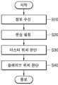
한편, 본 발명의 일 실시예에 따른 자율 작업 방법은, 마스터 작업 로봇 및 적어도 하나의 슬레이브 작업 로봇을 포함하는 자율 작업 시스템을 이용하는 자율 작업 방법으로서, 작업 대상 공간에 대한 정보를 수신하는 단계, 상기 마스터 작업 로봇의 이동 경로, 센싱 위치 및 상기 센싱 위치에서의 센싱 각도를 설정하는 단계, 상기 센싱 위치에서 획득된 센싱 데이터와 기준 맵 데이터를 비교하여 상기 마스터 작업 로봇의 위치를 판단하는 단계 및 상기 슬레이브 작업 로봇의 위치를 판단하는 단계를 포함할 수 있다.Meanwhile, an autonomous work method according to one embodiment of the present invention is an autonomous work method using an autonomous work system including a master work robot and at least one slave work robot, and may include a step of receiving information about a work target space, a step of setting a movement path, a sensing position, and a sensing angle at the sensing position of the master work robot, a step of comparing sensing data acquired at the sensing position with reference map data to determine a position of the master work robot, and a step of determining a position of the slave work robot.
또한, 상기 슬레이브 작업 로봇의 위치를 판단하는 단계는, 상기 마스터 작업 로봇의 위치 정보를 수신하는 단계 및 상기 슬레이브 작업 로봇과 상기 마스터 작업 로봇 사이의 거리 및 각도를 산출하는 단계를 포함할 수 있다.Additionally, the step of determining the position of the slave task robot may include the step of receiving position information of the master task robot and the step of calculating the distance and angle between the slave task robot and the master task robot.
또한, 상기 슬레이브 작업 로봇의 위치를 판단하는 단계에서는, 임의의 위치에 설치되는 송수신기로부터 출력되는 위치 신호를 수신하고, 상기 위치 신호로부터 상기 슬레이브 작업 로봇의 위치를 판단할 수 있다.In addition, in the step of determining the position of the slave task robot, a position signal output from a transceiver installed at an arbitrary position is received, and the position of the slave task robot can be determined from the position signal.
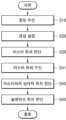
또한, 상기 마스터 작업 로봇이 상기 작업 대상 공간에 작업 정보를 표시하는 단계 및 상기 슬레이브 작업 로봇이 상기 작업 정보를 인식하고 인식 결과에 대응하는 작업을 수행하는 단계를 더 포함할 수 있다.In addition, the method may further include a step in which the master work robot displays work information in the work target space and a step in which the slave work robot recognizes the work information and performs a task corresponding to the recognition result.
또한, 상기 작업 정보는 상기 작업 정보가 표시된 위치에 대응하는 위치 정보를 더 포함하고, 상기 슬레이브 작업 로봇의 위치를 판단하는 단계에서는 상기 위치 정보를 이용하여 상기 슬레이브 작업 로봇의 위치를 판단할 수 있다.In addition, the work information further includes location information corresponding to a location where the work information is displayed, and in the step of determining the location of the slave work robot, the location information can be used to determine the location of the slave work robot.
한편, 본 발명에 따른 자율 작업 방법을 수행하기 위한 프로그램이 기록된 컴퓨터 판독 가능한 기록매체가 제공될 수 있다.Meanwhile, a computer-readable recording medium having recorded thereon a program for performing an autonomous operation method according to the present invention may be provided.
본 발명은 복수의 작업 장비를 이용하여 작업을 수행하되 단순한 구성을 통해 높은 정확도와 효율을 보장할 수 있는 자율 작업 시스템, 방법 및 컴퓨터 판독 가능한 기록매체를 제공할 수 있다.The present invention can provide an autonomous working system, method, and computer-readable recording medium that can perform work using a plurality of working equipment while ensuring high accuracy and efficiency through a simple configuration.
도 1은 본 발명에 따른 자율 작업 시스템이 적용되는 작업 로봇을 예시적으로 나타내는 도면이다.
도 2는 본 발명의 일 실시예에 따른 자율 작업 시스템의 구성을 개략적으로 나타내는 도면이다.
도 3은 본 발명의 다른 실시예에 따른 슬레이브 작업 로봇의 구성을 개략적으로 나타내는 도면이다.
도 4는 본 발명의 다른 실시예에 따른 자율 작업 시스템의 구성을 개략적으로 나타내는 도면이다.
도 5는 본 발명의 또 다른 실시예에 따른 자율 작업 시스템의 구성을 개략적으로 나타내는 도면이다.
도 6은 본 발명의 다른 실시예에 따른 자율 작업 시스템의 구성을 개략적으로 나타내는 도면이다.
도 7은 본 발명의 다른 실시예에 따른 마스터 작업 로봇의 구성을 개략적으로 나타내는 도면이다.
도 8은 마스터 작업 로봇과 슬레이브 작업 로봇의 상대적 위치를 통해 슬레이브 작업 로봇의 위치를 산출하는 방법을 예시적으로 나타내는 도면이다.
도 9는 본 발명에 따른 자율 작업 시스템이 적용되는 작업 로봇의 구성을 예시적으로 나타내는 도면이다.
도 10은 마스터 작업 로봇의 위치를 판단하기 위해 기준 맵 데이터와 스캔 데이터를 비교하는 데이터 변환 과정을 예시적으로 나타내는 도면이다.
도 11은 본 발명의 일 실시예에 따른 마스터 작업 로봇의 이동경로를 예시적으로 나타내는 도면이다.
도 12는 본 발명의 일 실시예에 따른 마스터 작업 로봇을 통해 획득되는 기준 맵을 예시적으로 나타내는 도면이다.
도 13은 본 발명의 일 실시예에 따른 자율 작업 방법을 개략적으로 나타내는 도면이다.
도 14는 본 발명의 다른 실시예에 따른 자율 작업 방법을 개략적으로 나타내는 도면이다.
도 15는 본 발명의 또 다른 실시예에 따른 자율 작업 방법을 개략적으로 나타내는 도면이다.Figure 1 is a drawing exemplarily showing a work robot to which an autonomous work system according to the present invention is applied.
FIG. 2 is a drawing schematically showing the configuration of an autonomous working system according to one embodiment of the present invention.
FIG. 3 is a drawing schematically showing the configuration of a slave task robot according to another embodiment of the present invention.
FIG. 4 is a drawing schematically showing the configuration of an autonomous working system according to another embodiment of the present invention.
FIG. 5 is a drawing schematically showing the configuration of an autonomous working system according to another embodiment of the present invention.
FIG. 6 is a drawing schematically showing the configuration of an autonomous working system according to another embodiment of the present invention.
FIG. 7 is a drawing schematically showing the configuration of a master task robot according to another embodiment of the present invention.
FIG. 8 is a drawing exemplarily showing a method for calculating the position of a slave task robot through the relative positions of a master task robot and a slave task robot.
Figure 9 is a drawing exemplarily showing the configuration of a work robot to which an autonomous work system according to the present invention is applied.
Figure 10 is a drawing exemplarily showing a data conversion process for comparing reference map data and scan data to determine the position of a master task robot.
FIG. 11 is a drawing exemplarily showing a movement path of a master task robot according to one embodiment of the present invention.
FIG. 12 is a drawing exemplarily showing a reference map acquired through a master task robot according to one embodiment of the present invention.
FIG. 13 is a drawing schematically illustrating an autonomous working method according to one embodiment of the present invention.
FIG. 14 is a drawing schematically illustrating an autonomous working method according to another embodiment of the present invention.
FIG. 15 is a drawing schematically illustrating an autonomous working method according to another embodiment of the present invention.
본 발명의 이점 및 특징, 그리고 그것들을 달성하는 방법은 첨부되는 도면과 함께 상세하게 설명되는 실시예들을 참조하면 명확해질 것이다. 그러나 본 발명은 아래에서 제시되는 실시예들로 한정되는 것이 아니라, 서로 다른 다양한 형태로 구현될 수 있고, 본 발명의 사상 및 기술 범위에 포함되는 모든 변환, 균등물 내지 대체물을 포함하는 것으로 이해되어야 한다. 아래에 제시되는 실시예들은 본 발명의 개시가 완전하도록 하며, 본 발명이 속하는 기술분야에서 통상의 지식을 가진 자에게 발명의 범주를 완전하게 알려주기 위해 제공되는 것이다. 본 발명을 설명함에 있어서 관련된 공지 기술에 대한 구체적인 설명이 본 발명의 요지를 흐릴 수 있다고 판단되는 경우, 그 상세한 설명을 생략한다.The advantages and features of the present invention, and the methods for achieving them, will become clear with reference to the embodiments described in detail together with the accompanying drawings. However, the present invention is not limited to the embodiments presented below, but can be implemented in various different forms, and it should be understood to include all transformations, equivalents, and substitutes included in the spirit and technical scope of the present invention. The embodiments presented below are provided to ensure that the disclosure of the present invention is complete, and to fully inform those skilled in the art of the present invention of the scope of the invention. In explaining the present invention, if it is determined that a specific description of a related known technology may obscure the gist of the present invention, the detailed description thereof will be omitted.
본 출원에서 사용한 용어는 단지 특정한 실시예를 설명하기 위해 사용된 것으로, 본 발명을 한정하려는 의도가 아니다. 단수의 표현은 문맥상 명백하게 다르게 뜻하지 않는 한, 복수의 표현을 포함한다. 본 출원에서, "포함한다" 또는 "가지다" 등의 용어는 명세서상에 기재된 특징, 숫자, 단계, 동작, 구성요소, 부품 또는 이들을 조합한 것이 존재함을 지정하려는 것이지, 하나 또는 그 이상의 다른 특징들이나 숫자, 단계, 동작, 구성요소, 부품 또는 이들을 조합한 것들의 존재 또는 부가 가능성을 미리 배제하지 않는 것으로 이해되어야 한다. 제1, 제2 등의 용어는 다양한 구성요소들을 설명하는데 사용될 수 있지만, 구성요소들은 상기 용어들에 의해 한정되어서는 안 된다. 상기 용어들은 하나의 구성요소를 다른 구성요소로부터 구별하는 목적으로만 사용된다.The terminology used in this application is only used to describe specific embodiments and is not intended to limit the present invention. The singular expression includes the plural expression unless the context clearly indicates otherwise. In this application, it should be understood that the terms "comprises" or "has" and the like are intended to specify the presence of a feature, number, step, operation, component, part or combination thereof described in the specification, but do not exclude in advance the possibility of the presence or addition of one or more other features, numbers, steps, operations, components, parts or combinations thereof. The terms first, second, etc. may be used to describe various components, but the components should not be limited by the terms. The terms are used only for the purpose of distinguishing one component from another.
도 1은 본 발명에 따른 자율 작업 시스템이 적용되는 작업 로봇을 예시적으로 나타내는 도면이다.Figure 1 is a drawing exemplarily showing a work robot to which an autonomous work system according to the present invention is applied.
본 발명에 따른 자율 작업 시스템은 복수의 작업 로봇을 이용하여 작업 공간에서 다양한 작업을 수행할 수 있다. 기본적으로 상기 복수의 작업 로봇은 작업 공간에서 자신의 위치를 판단할 수 있고, 자신이 작업을 수행할 위치에서 자신에게 할당된 작업을 수행할 수 있다.The autonomous work system according to the present invention can perform various tasks in a work space by using a plurality of work robots. Basically, the plurality of work robots can determine their own positions in the work space and perform tasks assigned to them at the positions where they are to perform the tasks.
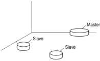
도 1을 참조하면, 본 발명에 따른 자율 작업 시스템은 복수의 작업 로봇을 통해 구현될 수 있다. 상기 복수의 작업 로봇은 적어도 하나의 마스터 작업 로봇(Master)과 적어도 하나의 슬레이브 작업 로봇(Slave)을 포함할 수 있다. 상기 마스터 작업 로봇은 작업 대상 공간에서 스스로 자신의 위치를 판단할 수 있으며, 상기 슬레이브 작업 로봇이 수행할 작업에 대한 정보를 표시할 수 있다.Referring to Fig. 1, the autonomous work system according to the present invention can be implemented through a plurality of work robots. The plurality of work robots can include at least one master work robot (Master) and at least one slave work robot (Slave). The master work robot can determine its own position in the work target space and display information about the work to be performed by the slave work robot.
상기 슬레이브 작업 로봇은 상기 마스터 작업 로봇의 위치를 바탕으로 자신의 위치를 판단할 수 있고, 상기 마스터 작업 로봇이 표시한 정보를 분석하여 자신이 수행할 작업을 인식하고 인식된 작업을 수행할 수 있다.The above slave task robot can determine its own location based on the location of the master task robot, recognize the task it is to perform by analyzing the information displayed by the master task robot, and perform the recognized task.
본 명세서에서는 작업 로봇으로 명명하도록 하나, 로봇(robot)은 발명의 설명만을 위해 사용할 뿐 본 발명의 권리범위가 반드시 로봇이라는 용어에 의해 한정되는 것은 아니다.In this specification, the term “working robot” is used only to describe the invention, and the scope of the rights of the present invention is not necessarily limited by the term “robot.”
상기 마스터 작업 로봇과 슬레이브 작업 로봇은 구동력을 제공하는 구동 장치를 포함하여 작업 공간에서 자유롭게 이동할 수 있고, 지상뿐만 아니라 공중 및 수중에서도 이동 가능한 것으로 이해할 수 있다.The above master task robot and slave task robot can be understood to be capable of freely moving in a task space, including a driving device that provides driving force, and capable of moving not only on the ground but also in the air and underwater.
한편, 도 1에는 하나의 마스터 작업 로봇과 두 개의 슬레이브 작업 로봇이 도시되어 있으나, 이는 설명을 위한 예시에 불과할 뿐 특정 개수로 본 발명의 권리범위가 제한되는 것은 아니다.Meanwhile, although FIG. 1 illustrates one master working robot and two slave working robots, this is merely an example for explanation and the scope of the present invention is not limited to a specific number.
도 2는 본 발명의 일 실시예에 따른 자율 작업 시스템의 구성을 개략적으로 나타내는 도면이다.FIG. 2 is a drawing schematically showing the configuration of an autonomous working system according to one embodiment of the present invention.
도 2를 참조하면, 본 발명의 일 실시예에 따른 자율 작업 시스템(100)은 적어도 하나의 마스터 작업 로봇(10) 및 적어도 하나의 슬레이브 작업 로봇(20)을 포함한다. 한편, 마스터 작업 로봇(10)은 데이터 수신부(11), 센싱부(12), 센싱 설정부(13) 및 제1 위치 판단부(14)를 포함하고, 슬레이브 작업 로봇(20)은 제2 위치 판단부(21)를 포함할 수 있다.Referring to FIG. 2, an autonomous work system (100) according to one embodiment of the present invention includes at least one master work robot (10) and at least one slave work robot (20). Meanwhile, the master work robot (10) may include a data receiving unit (11), a sensing unit (12), a sensing setting unit (13), and a first position determining unit (14), and the slave work robot (20) may include a second position determining unit (21).
데이터 수신부(11)는 작업 대상 공간에 대한 정보를 수신한다. 상기 작업 대상 공간은 마스터 작업 로봇(10) 및 슬레이브 작업 로봇(20)이 작업을 수행하는 공간을 의미하며, 데이터 수신부(11)가 수신하는 정보는 상기 작업 대상 공간에 대응하는 도면, 상기 작업 대상 공간에 존재하는 벽, 기둥, 창문 등의 위치와 크기에 관한 정보, 요컨대 상기 작업 대상 공간의 건축적, 공간적 요소에 관한 정보를 포함할 수 있다. 또한, 데이터 수신부(11)는 마스터 작업 로봇(10)과 슬레이브 작업 로봇(20)이 상기 작업 대상 공간에서 수행해야 하는 작업(task)에 관한 정보를 수신할 수 있다.The data receiving unit (11) receives information about a work target space. The work target space refers to a space where a master work robot (10) and a slave work robot (20) perform work, and the information received by the data receiving unit (11) may include a drawing corresponding to the work target space, information about the position and size of walls, pillars, windows, etc. existing in the work target space, and in short, information about architectural and spatial elements of the work target space. In addition, the data receiving unit (11) may receive information about a task that the master work robot (10) and the slave work robot (20) must perform in the work target space.
한편, 상기 작업 대상 공간에 대한 정보는 마스터 작업 로봇(10) 및 슬레이브 작업 로봇(20)의 허용 이동 범위에 관한 정보를 포함할 수 있다. 예컨대, 상기 작업 대상 공간은 벽, 기둥, 창문 등이 설치되어야 하는 공간을 포함할 수 있으며, 설치 이전에는 마스터 작업 로봇(10) 및 슬레이브 작업 로봇(20)으로 하여금 진입하지 못하도록 방지해야 하는 공간이 존재할 수 있다. 벽이 세워지거나, 엘리베이터가 설치되어야 하는 공간은 실제 작업이 이루어지기 전에는 바닥면이 단절되어 있을 수 있으며, 경우에 따라서는 마스터 작업 로봇(10) 및 슬레이브 작업 로봇(20)이 추락할 위험이 있을 수 있다. 따라서, 상기 작업 대상 공간에 대한 정보는 상기 허용 이동 범위에 관한 정보를 포함하여, 마스터 작업 로봇(10) 및 슬레이브 작업 로봇(20)의 이동 범위를 제한하도록 할 수 있다.Meanwhile, the information on the work target space may include information on the allowable movement range of the master work robot (10) and the slave work robot (20). For example, the work target space may include a space where a wall, a pillar, a window, etc. are to be installed, and there may be a space where the master work robot (10) and the slave work robot (20) must be prevented from entering before installation. A space where a wall is to be built or an elevator is to be installed may have a floor that is disconnected before actual work is performed, and in some cases, there may be a risk of the master work robot (10) and the slave work robot (20) falling. Therefore, the information on the work target space may include information on the allowable movement range to limit the movement range of the master work robot (10) and the slave work robot (20).
데이터 수신부(11)는 센싱부(12)와 유선 또는 무선, 전기적 또는 비전기적으로 연결되어 센싱부(12)로부터 획득되는 데이터를 수신할 수 있다. 선택적으로, 데이터 수신부(11)는 USB 포트, CD-ROM 등과 같은 외부 저장매체가 연결될 수 있는 단자를 포함하여, 상기 외부 저장매체에 저장된 상기 작업 대상 공간에 대한 데이터를 수신할 수도 있다. 선택적으로, 상기 데이터 수신부(11)는 도시되지 않은 별도의 입력부와 전기적으로 연결되어, 입력부로부터 입력되는 상기 작업 대상 공간에 대한 데이터를 수신할 수 있다. 선택적으로, 상기 데이터 수신부(11)는 별도의 컴퓨팅 장치와 전기적으로 연결되어 컴퓨팅 장치로부터 상기 작업 대상 공간에 대한 데이터를 수신할 수 있다.The data receiving unit (11) can be connected to the sensing unit (12) by wire or wirelessly, electrically or non-electrically, and receive data acquired from the sensing unit (12). Optionally, the data receiving unit (11) can include a terminal to which an external storage medium such as a USB port, a CD-ROM, etc. can be connected, and can receive data about the work target space stored in the external storage medium. Optionally, the data receiving unit (11) can be electrically connected to a separate input unit (not shown) and receive data about the work target space input from the input unit. Optionally, the data receiving unit (11) can be electrically connected to a separate computing device and receive data about the work target space from the computing device.
센싱부(12)는 상기 작업 대상 공간을 센싱한다. 센싱부(12)는 적어도 하나의 센서 및 상기 센서의 회전 동작을 제어하는 모터와 같은 구동부를 포함할 수 있으나, 반드시 이에 제한되는 것은 아니며, 상기 센서의 센싱 범위가 360°인 경우에는 상기 모터와 같은 구동부가 포함되지 않을 수 있다. 한편, 도 2에 도시되는 마스터 작업 로봇(10)은 데이터 수신부(11), 센싱부(12), 센싱 설정부(13) 및 제1 위치 판단부(14)를 모두 포함하는 것으로 도시되어 있으나, 센싱 설정부(13) 및 제1 위치 판단부(14)는 마스터 작업 로봇(10)과 이격된 위치에 독립적으로 존재할 수도 있다.The sensing unit (12) senses the work target space. The sensing unit (12) may include at least one sensor and a driving unit such as a motor that controls the rotational motion of the sensor, but is not necessarily limited thereto, and if the sensing range of the sensor is 360°, the driving unit such as the motor may not be included. Meanwhile, the master work robot (10) illustrated in FIG. 2 is illustrated as including all of the data receiving unit (11), the sensing unit (12), the sensing setting unit (13), and the first position determining unit (14), but the sensing setting unit (13) and the first position determining unit (14) may exist independently at a location separate from the master work robot (10).
한편, 상기 센서는 상기 작업 대상 공간을 센싱할 수 있는 다양한 종류의 센서가 사용될 수 있는 데, 예컨대 사물까지의 거리를 측정하거나 사물의 형태를 센싱하거나 마스터 작업 로봇(10)의 이동을 센싱할 수 있다. 이러한 센서는, 레이저를 이용하거나 음파, 광파 및/또는 전파를 이용하는 센서, IMU 센서, GPS 센서를 포함할 수 있으며, 및/또는 카메라와 같이 동영상 및/또는 정지 영상를 취득할 수 있는 영상 취득 센서를 포함할 수 있다. 상기 센서가 레이저 센서를 포함하는 경우 상기 레이저 센서의 일 예로서 라이더(LiDAR) 센서가 포함될 수 있다.Meanwhile, the sensor may use various types of sensors capable of sensing the work target space, for example, measuring the distance to an object, sensing the shape of an object, or sensing the movement of the master work robot (10). Such sensors may include sensors that utilize lasers, sound waves, light waves, and/or radio waves, IMU sensors, GPS sensors, and/or image acquisition sensors capable of acquiring video and/or still images, such as cameras. When the sensor includes a laser sensor, an example of the laser sensor may include a LiDAR sensor.
센싱부(12)는 이러한 센서를 적어도 하나 이상 포함할 수 있으며, 다른 종류의 복수의 센서를 조합함으로써 센싱 정밀도를 향상시킬 수 있다. 예컨대 레이저 센서로서 라이더 센서를 사용하고, IMU 센서를 더 포함해 마스터 작업 로봇(10)의 움직임을 센싱함으로써 작업 대상 공간에 대한 센싱 정밀도를 향상시킬 수 있다. 또한, 선택적 및/또는 부가적으로 카메라 센서를 포함해, 카메라 센서로 하여금 작업 대상 공간을 촬영하도록 할 수 있는 데, 예컨대 작업 대상 공간의 특정 면, 구체적으로 바닥면에 대한 상태 및/또는 질감을 촬영하고 이를 통해 마스터 작업 로봇(10) 및/또는 슬레이브 작업 로봇(20)의 이동 및/또는 작업 경로를 설정 및/또는 보정하도록 할 수 있다. 또한, 선택적 및/또는 부가적으로 거리 측정 센서를 포함해, 특정 포인트, 예컨대 벽이나 기둥까지의 거리를 측정할 수 있다. 이로 인해 상기 작업 대상 공간에 존재하는 특정 포인트의 계측된 위치를 마스터 작업 로봇(10) 및/또는 슬레이브 작업 로봇(20)의 이동 및/또는 작업 경로를 설정 및/또는 보정하는 데에 반영하도록 할 수 있다. 상기와 같은 센싱부(12)의 다양한 센서 조합은 반드시 마스터 작업 로봇(10)에만 설치될 필요는 없으며, 센싱부(12)를 구성하는 일부 센서는 슬레이브 작업 로봇(20)에 설치되고, 그 데이터가 마스터 작업 로봇(10)과 통신되도록 함으로써 작업 전 및/또는 작업 도중에 마스터 작업 로봇(10) 및/또는 슬레이브 작업 로봇(20)의 이동 및/또는 작업 경로를 설정 및/또는 보정하도록 할 수 있다. 이러한 센싱부의 구성은 본 명세서의 모든 실시예들에 적용될 수 있다.The sensing unit (12) may include at least one of these sensors, and may improve the sensing precision by combining multiple sensors of different types. For example, a lidar sensor may be used as a laser sensor, and an IMU sensor may be further included to sense the movement of the master task robot (10), thereby improving the sensing precision for the task target space. In addition, a camera sensor may be optionally and/or additionally included, and the camera sensor may be configured to photograph the task target space, for example, photograph the condition and/or texture of a specific surface of the task target space, specifically, the floor surface, and thereby set and/or correct the movement and/or work path of the master task robot (10) and/or the slave task robot (20). In addition, a distance measuring sensor may be optionally and/or additionally included, and the distance to a specific point, for example, a wall or a pillar, may be measured. As a result, the measured position of a specific point existing in the task target space may be reflected in setting and/or correcting the movement and/or work path of the master task robot (10) and/or the slave task robot (20). The various sensor combinations of the sensing unit (12) as described above do not necessarily have to be installed only in the master task robot (10), and some of the sensors constituting the sensing unit (12) may be installed in the slave task robot (20), and the data thereof may be communicated to the master task robot (10), thereby enabling the movement and/or task path of the master task robot (10) and/or the slave task robot (20) to be set and/or corrected before and/or during the task. This configuration of the sensing unit may be applied to all embodiments of the present specification.
마스터 작업 로봇(10)은 상기 센서를 이용하여 주변 공간을 센싱할 수 있으며, 상기 센서에서 출력된 신호가 반사되는 정보를 이용하여 주변 공간에 있는 사물의 위치를 극좌표 형식으로 획득할 수 있다. 상기 모터는 상기 센서를 원하는 각도만큼 회전할 수 있도록 하며, 예컨대 360˚ 회전하도록 할 수 있다. 상기 센서의 회전 방향은 필요에 따라 다양하게 제어될 수 있다.The master task robot (10) can sense the surrounding space using the sensor, and can obtain the location of an object in the surrounding space in polar coordinate format using the information reflected from the signal output from the sensor. The motor can rotate the sensor by a desired angle, for example, 360˚. The rotation direction of the sensor can be controlled in various ways as needed.
한편, 상기 센서는 별도의 구동부에 의하여 수평 회전, 수평 이동, 틸트 및/또는 수직 이동이 제어될 수 있다. 상기 센서의 수평 회전, 수평 이동, 틸트 및/또는 수직 이동은 서로 독립적으로 제어될 수 있으며, 상기 수평 회전, 수평 이동, 틸트 및/또는 수직 이동을 제어하기 위한 제어 신호 또한 독립적으로 생성되어 상기 구동부에 제공될 수 있다.Meanwhile, the sensor may be controlled for horizontal rotation, horizontal movement, tilt and/or vertical movement by a separate driving unit. The horizontal rotation, horizontal movement, tilt and/or vertical movement of the sensor may be controlled independently of each other, and a control signal for controlling the horizontal rotation, horizontal movement, tilt and/or vertical movement may also be independently generated and provided to the driving unit.
센싱 설정부(13)는 마스터 작업 로봇(10)의 이동 경로, 센싱 위치 및 센싱부(12)의 센싱 각도를 설정할 수 있다. 구체적으로, 센싱 설정부(13)는 상기 이동 경로를 설정하고, 상기 이동 경로 상의 임의의 지점을 지정하여 지정된 상기 지점을 센싱 위치로 설정한다. 그리고, 상기 센싱 위치는 상기 작업 대상 공간에 따라 필요한 경우 복수 개의 위치로 설정될 수 있다. 이에 대응하여 마스터 작업 로봇(10)이 상기 센싱 위치에 도달하면 상기 센서는 센싱 동작, 예를 들면 스캐닝 동작을 수행한다. 그리고 이때, 상기 센서는 센싱 설정부(13)에 의해 설정된 센싱 각도에 따라 회전하게 된다.The sensing setting unit (13) can set the movement path of the master work robot (10), the sensing position, and the sensing angle of the sensing unit (12). Specifically, the sensing setting unit (13) sets the movement path, designates an arbitrary point on the movement path, and sets the designated point as a sensing position. In addition, the sensing position can be set to a plurality of positions, if necessary, depending on the work target space. In response, when the master work robot (10) reaches the sensing position, the sensor performs a sensing operation, for example, a scanning operation. In this case, the sensor rotates according to the sensing angle set by the sensing setting unit (13).
한편, 본 발명의 다른 실시예에서 상기 센서는 센싱 높이가 조절될 수 있으며, 센싱 설정부(13)는 설정된 센싱 위치에서 상기 센서의 센싱 각도 및 센싱 높이를 함께 설정할 수 있다. 그리고, 상기 센싱 위치와 센싱 각도는 상기 작업 대상 공간의 특성을 고려하여 설정될 수 있다.Meanwhile, in another embodiment of the present invention, the sensor can have an adjustable sensing height, and the sensing setting unit (13) can set the sensing angle and sensing height of the sensor together at the set sensing position. In addition, the sensing position and sensing angle can be set in consideration of the characteristics of the work target space.
또한, 빛을 반사하지 않고 투과하는 등, 센싱 데이터를 획득하기 어려운 경우, 상기 센싱 위치와 센싱 각도는 상기 작업 대상 공간 내의 비어있는 공간에 배치되어 기둥이나 장애물 등을 센싱할 수 있는 위치와 각도로 설정될 수 있다.In addition, in cases where it is difficult to obtain sensing data, such as when light is transmitted rather than reflected, the sensing position and sensing angle may be set to a position and angle that can sense pillars or obstacles, etc., by being placed in an empty space within the work target space.
한편, 상기 작업 대상 공간의 도면이 존재하는 경우, 센싱 설정부(13)는 상기 도면을 고려하여 상기 이동 경로, 센싱 위치 및 센싱 위치에서의 상기 센서의 센싱 각도를 설정할 수 있다.Meanwhile, if a drawing of the work target space exists, the sensing setting unit (13) can set the movement path, sensing position, and sensing angle of the sensor at the sensing position by considering the drawing.
마스터 작업 로봇(10)은 상기 이동 경로 상에서 특정한 위치에서 센싱 동작을 수행하는 것으로 이해할 수 있다. 그리고, 상기 특정한 센싱 위치가 지정되는 것은 마스터 작업 로봇(10)의 위치를 정확하게 파악하기 위함이다.It can be understood that the master task robot (10) performs a sensing operation at a specific location on the above movement path. In addition, the specific sensing location is designated to accurately determine the location of the master task robot (10).
상기 특정한 위치는 유한한 개수의 위치로 설정될 수 있으나, 반드시 이에 제한되는 것은 아니며 상기 이동 경로 상에서 이동하며 연속적으로 센싱 동작을 수행할 수도 있다.The above specific location may be set to a finite number of locations, but is not necessarily limited thereto, and may also perform sensing operations continuously while moving along the above movement path.
한편, 상기 센싱 각도는 각각의 센싱 위치에서 상기 센서의 센싱 각도를 의미하며 Degree 또는 Radian 단위로 표현 가능하다. 그리고, 상기 센싱 각도의 크기는 특정 좌표축, 예컨대 x축을 기준으로 표현되거나, 직전 센싱 위치에서의 센싱 동작이 종료된 시점에서 상기 센서의 각도를 기준으로 표현될 수 있다.Meanwhile, the sensing angle refers to the sensing angle of the sensor at each sensing position and can be expressed in units of Degree or Radian. In addition, the size of the sensing angle can be expressed based on a specific coordinate axis, for example, the x-axis, or can be expressed based on the angle of the sensor at the point in time when the sensing operation at the previous sensing position is finished.
이처럼 마스터 작업 로봇(10)의 이동 경로, 센싱 위치 및 센싱부(12)의 센싱 각도를 설정하도록 상기 센싱 설정부는 마스터 작업 로봇(10)의 복수의 구동부에 동작 신호를 보낼 수 있다.In this way, the sensing setting unit can send operation signals to multiple driving units of the master task robot (10) to set the movement path of the master task robot (10), the sensing position, and the sensing angle of the sensing unit (12).
본 발명의 일 실시예에서, 각각의 상기 센싱 위치에서 마스터 작업 로봇(10)은 정지하며, 상기 센싱 위치에 정지한 상태에서 상기 센서를 회전시켜 주변 공간을 센싱, 예를 들면 스캐닝 할 수 있다. 또는, 본 발명의 다른 실시예에서 마스터 작업 로봇(10)은 상기 센싱 위치에서 정지하지 않을 수 있으며, 이동하며 상기 센서를 통해 주변 공간을 센싱, 예를 들면 스캐닝 할 수 있다. 제1 위치 판단부(14)는 상기 복수의 센싱 위치에서 센싱부(12)를 통해 획득된 센싱 데이터와 기준 맵 데이터를 비교하여 마스터 작업 로봇(10)의 위치를 판단한다.In one embodiment of the present invention, the master task robot (10) stops at each of the sensing positions, and while stopped at the sensing positions, the sensor can be rotated to sense, for example, scan, the surrounding space. Alternatively, in another embodiment of the present invention, the master task robot (10) may not stop at the sensing positions, but may move and sense, for example, scan, the surrounding space through the sensor. The first position determination unit (14) compares the sensing data acquired through the sensing unit (12) at the plurality of sensing positions with the reference map data to determine the position of the master task robot (10).
상기 기준 맵 데이터는 이미지 프레임에 포함되는 픽셀의 좌표로 표현될 수 있으며, 물체가 존재하는 위치에 대응하는 픽셀의 좌표는 비어있는 위치에 대응하는 픽셀의 좌표와 다른 값을 가질 수 있다. 앞서 설명한 바와 같이, 상기 센서를 통해 획득되는 데이터는 극좌표 형태로 획득될 수 있으며 상기 기준 맵 데이터와 상기 센싱 데이터를 비교하면, 상기 작업 대상 공간 내에서의 마스터 작업 로봇(10)의 위치를 판단할 수 있다.The above reference map data can be expressed as coordinates of pixels included in the image frame, and the coordinates of pixels corresponding to positions where objects exist can have different values from the coordinates of pixels corresponding to empty positions. As described above, data acquired through the sensor can be acquired in the form of polar coordinates, and by comparing the reference map data and the sensing data, the position of the master work robot (10) within the work target space can be determined.
보다 구체적으로, 제1 위치 판단부(14)는 상기 기준 맵 데이터를 상기 센서를 통해 획득되는 극좌표 형태의 데이터로 변환하고, 변환된 데이터와 상기 센싱 데이터를 비교할 수 있다.More specifically, the first position determination unit (14) can convert the reference map data into polar coordinate data obtained through the sensor, and compare the converted data with the sensing data.
다른 실시예에서, 제1 위치 판단부(14)는 임의의 위치에 설치되는 송수신기(미도시)로부터 출력된 위치 신호를 수신하고, 상기 위치 신호로부터 상기 마스터 작업 로봇의 위치를 판단할 수 있다. 상기 송수신기의 위치가 결정되면 상기 송수신기는 자신의 위치를 기준으로 하여 마스터 작업 로봇(10)의 위치를 판단하고, 판단된 위치 정보를 제1 위치 판단부(14)에 제공할 수 있다. 이러한 송수신기는 실내에 설치되어 마스터 작업 로봇과 교신함으로써 마스터 작업 로봇(10)의 위치 판단에 도움을 줄 수 있다. 다른 예로서, 상기 송수신기는, 예컨대 건물의 네 모서리에 설치되어 GPS 신호를 수신함으로써 건물의 좌표값을 인식한 후, 그 값을 바탕으로 새로운 신호를 송신하여 마스터 작업 로봇(10)의 위치 판단에 도움을 줄 수 있다.In another embodiment, the first position determination unit (14) may receive a position signal output from a transceiver (not shown) installed at an arbitrary location, and determine the position of the master task robot from the position signal. When the position of the transceiver is determined, the transceiver may determine the position of the master task robot (10) based on its own position, and provide the determined position information to the first position determination unit (14). Such a transceiver may be installed indoors and communicate with the master task robot to assist in determining the position of the master task robot (10). As another example, the transceiver may be installed at, for example, four corners of a building to receive GPS signals, recognize the coordinate values of the building, and then transmit a new signal based on the values to assist in determining the position of the master task robot (10).
또는, 제1 위치 판단부(14)가 마스터 작업 로봇(10)으로부터 상기 송수신기까지의 거리, 각도 데이터 및 상기 송수신기의 위치 정보를 고려하여 마스터 작업 로봇(10)의 위치를 판단하는 것도 가능할 것이다.선택적으로, 제1 위치 판단부(14)는 임의의 위치에 설치되는 마커(미도시)의 위치를 센싱하고, 상기 마커로부터 상기 마스터 작업 로봇의 위치를 판단할 수 있다. 예컨대 제1 위치 판단부(14)는 상기 마커의 위치를 센싱한 위치 및/또는 센싱한 데이터의 분석으로부터 역으로 마스터 작업 로봇(10)의 위치를 판단할 수 있다.Alternatively, the first position determination unit (14) may determine the position of the master task robot (10) by considering the distance from the master task robot (10) to the transceiver, angle data, and position information of the transceiver. Optionally, the first position determination unit (14) may sense the position of a marker (not shown) installed at an arbitrary position, and determine the position of the master task robot from the marker. For example, the first position determination unit (14) may determine the position of the master task robot (10) inversely from analysis of the sensed position of the marker and/or the sensed data.
제1 위치 판단부(14)가 수행하는 동작은 마스터 작업 로봇(10)의 위치를 최대한 정확하게 판단하는 것을 목적으로 하며, 상기 송수신기 및/또는 마커는 상기 작업 대상 공간의 임의의 위치, 예컨대 기둥 또는 벽면에 부착되어 상기 위치 신호를 송신 및/또는 위치를 표시할 수 있다.The operation performed by the first position determination unit (14) is intended to determine the position of the master work robot (10) as accurately as possible, and the transceiver and/or marker can be attached to any position in the work target space, such as a pillar or wall, to transmit the position signal and/or display the position.
다만, 상기 송수신기 및/또는 마커의 위치가 상기 센싱 대상 공간의 내부의 임의의 위치로 한정되는 것은 아니다. 예컨대, 상기 작업 대상 공간이 오픈된 공간인 경우에는 상기 송수신기 및/또는 마커가 상기 작업 대상 공간의 외부에 위치하더라도 마스터 작업 로봇(10)의 위치를 추척할 수 있다.However, the location of the transceiver and/or marker is not limited to any arbitrary location inside the sensing target space. For example, if the work target space is an open space, the location of the master work robot (10) can be tracked even if the transceiver and/or marker is located outside the work target space.
마스터 작업 로봇(10)은 상기 위치 신호를 수신하여 수신한 상기 위치 신호를 송신한 송수신기의 위치 및 상기 송수신기까지의 거리 및/또는 각도를 판단할 수 있는 수신기(미도시)를 포함할 수 있으며, 상기 수신기는 적어도 하나의 송수신기로부터 수신한 위치 신호를 고려하여 마스터 작업 로봇(10)의 위치를 판단할 수 있다.The master task robot (10) may include a receiver (not shown) capable of receiving the position signal and determining the position of the transceiver that transmitted the received position signal and the distance and/or angle to the transceiver, and the receiver may determine the position of the master task robot (10) by considering the position signal received from at least one transceiver.
상기 송수신기는 신호 공유기 또는 비콘(beacon)을 통해 구성될 수 있으며, 상기 센싱 데이터와 기준 맵 데이터의 비교를 통해 마스터 작업 로봇(10)의 정확한 위치를 판단하기 용이하지 않은 경우에 사용될 수 있다.The above transceiver can be configured via a signal sharer or a beacon, and can be used in cases where it is not easy to determine the exact location of the master work robot (10) by comparing the sensing data with reference map data.
상기 마커는 특정한 색상이나 모양 또는 미리 결정된 숫자를 표시할 수 있으며, 마스터 작업 로봇(10)은 상기 색상, 모양 또는 숫자를 인식할 수 있는 인식 수단을 포함함으로써 상기 마스터 작업 로봇의 위치를 판단할 수 있다. 한편, 상기 마커는 자외선 카메라와 같은 특수한 장치를 통해 식별 가능하도록 표시될 수 있다.The above marker may display a specific color or shape or a predetermined number, and the master task robot (10) may determine the position of the master task robot by including a recognition means capable of recognizing the color, shape or number. Meanwhile, the marker may be displayed so as to be identifiable through a special device such as an ultraviolet camera.
한편, 슬레이브 작업 로봇(20)의 제2 위치 판단부(21)는 슬레이브 작업 로봇(20)의 위치를 판단한다. 제2 위치 판단부(21)가 슬레이브 작업 로봇(20)의 위치를 판단하기 위해서 다양한 방법을 사용할 수 있는데, 제1 위치 판단부(14)가 마스터 작업 로봇(10)의 위치를 판단하기 위해 사용하는 방법이 적용될 수 있다. 예컨대, 제2 위치 판단부(21)는 임의의 위치에 설치되는 송수신기로부터 출력되는 위치 신호를 수신하고, 상기 위치 신호로부터 슬레이브 작업 로봇(20)의 위치를 판단할 수 있다. 선택적으로 제2 위치 판단부(21)는 임의의 위치에 설치되는 마커의 위치를 센싱함으로써 슬레이브 작업 로봇(20)의 위치를 판단할 수 있다. 상기 제2 위치 판단부(21)가 슬레이브 작업 로봇(20)의 위치를 판단하는 구체적인 방법은 제1 위치 판단부(14)가 마스터 작업 로봇(10)의 위치를 판단하는 구체적인 방법과 동일하므로, 상세한 설명은 생략한다.Meanwhile, the second position determination unit (21) of the slave task robot (20) determines the position of the slave task robot (20). The second position determination unit (21) can use various methods to determine the position of the slave task robot (20), and the method used by the first position determination unit (14) to determine the position of the master task robot (10) can be applied. For example, the second position determination unit (21) can receive a position signal output from a transceiver installed at an arbitrary position, and determine the position of the slave task robot (20) from the position signal. Optionally, the second position determination unit (21) can determine the position of the slave task robot (20) by sensing the position of a marker installed at an arbitrary position. The specific method by which the second position determination unit (21) determines the position of the slave task robot (20) is the same as the specific method by which the first position determination unit (14) determines the position of the master task robot (10), and therefore, a detailed description thereof will be omitted.
또는, 제2 위치 판단부(21)는 마스터 작업 로봇(10)의 위치 정보와 슬레이브 작업 로봇(20)과 마스터 작업 로봇(10)의 상대적인 위치 관계를 고려하여 슬레이브 작업 로봇(20)의 위치를 판단할 수도 있다.Alternatively, the second position determination unit (21) may determine the position of the slave task robot (20) by considering the position information of the master task robot (10) and the relative positional relationship between the slave task robot (20) and the master task robot (10).
예컨대, 제2 위치 판단부(21)는 마스터 작업 로봇(10)의 위치 정보를 수신하고, 수신된 상기 위치와 슬레이브 작업 로봇(20)과 마스터 작업 로봇(10) 사이의 거리 및 각도를 고려하여 슬레이브 작업 로봇(20)의 위치를 판단할 수 있다.For example, the second position determination unit (21) can receive position information of the master task robot (10) and determine the position of the slave task robot (20) by considering the received position and the distance and angle between the slave task robot (20) and the master task robot (10).
마스터 작업 로봇(10)은 제1 위치 판단부(14)를 통해 스스로 자신의 위치를 판단할 수 있고, 마스터 작업 로봇(10)의 위치 정보는 슬레이브 작업 로봇(20)에 제공될 수 있다. 이때, 마스터 작업 로봇(10)과 슬레이브 작업 로봇(20) 사이의 상대적 위치 정보, 예컨대 각도 정보가 얻어진다면 마스터 작업 로봇(10)의 위치 정보를 이용하여 슬레이브 작업 로봇(20)의 위치를 판단할 수 있다.The master task robot (10) can determine its own position through the first position determination unit (14), and the position information of the master task robot (10) can be provided to the slave task robot (20). At this time, if relative position information, such as angle information, between the master task robot (10) and the slave task robot (20) is obtained, the position information of the master task robot (10) can be used to determine the position of the slave task robot (20).
한편, 제2 위치 판단부(21)는 제1 위치 판단부(14)로부터 마스터 작업 로봇(10)의 위치 정보를 실시간으로 제공받을 수 있다. 마스터 작업 로봇(10)과 슬레이브 작업 로봇(20)은 상기 작업 대상 공간에서 지속적으로 움직일 수 있으므로 마스터 작업 로봇(10)의 위치 정보가 실시간으로 제공될 경우에는 슬레이브 작업 로봇(20)의 위치를 보다 정확하게 판단할 수 있다.Meanwhile, the second position determination unit (21) can receive the position information of the master task robot (10) in real time from the first position determination unit (14). Since the master task robot (10) and the slave task robot (20) can continuously move in the work target space, if the position information of the master task robot (10) is provided in real time, the position of the slave task robot (20) can be determined more accurately.
이어지는 도면을 참조하여 제2 위치 판단부(21)가 슬레이브 작업 로봇(20)의 위치를 판단하는 방법의 일 예를 보다 구체적으로 설명하도록 한다.Referring to the following drawing, an example of a method by which the second position determination unit (21) determines the position of the slave work robot (20) will be described in more detail.
도 3은 본 발명의 다른 실시예에 따른 슬레이브 작업 로봇의 구성을 개략적으로 나타내는 도면이다.FIG. 3 is a drawing schematically showing the configuration of a slave task robot according to another embodiment of the present invention.
도 3을 참조하면, 본 발명의 다른 실시예에 따른 슬레이브 작업 로봇(20)은 제2 위치 판단부(21)와 거리 측정부(22)를 포함한다. 제2 위치 판단부(21)는 슬레이브 작업 로봇(20)의 위치를 판단하는데, 이때 거리 측정부(22)에서 측정한 거리 정보를 이용할 수 있다.Referring to Fig. 3, a slave task robot (20) according to another embodiment of the present invention includes a second position determination unit (21) and a distance measurement unit (22). The second position determination unit (21) determines the position of the slave task robot (20), and at this time, distance information measured by the distance measurement unit (22) can be used.
예컨대, 거리 측정부(22)는 슬레이브 작업 로봇(20)으로부터 마스터 작업 로봇(10)까지의 거리를 측정하거나, 상기 작업 대상 공간의 특정 지점까지의 거리를 측정할 수 있다. 또한, 거리 측정부(22)는 슬레이브 작업 로봇(20)과 마스터 작업 로봇(10) 사이의 각도를 더 측정할 수 있다.For example, the distance measuring unit (22) can measure the distance from the slave working robot (20) to the master working robot (10), or the distance to a specific point in the work target space. In addition, the distance measuring unit (22) can further measure the angle between the slave working robot (20) and the master working robot (10).
거리 측정부(22)는 거리를 측정하기 위해 레이저 방식을 이용하거나 GPS 방식을 이용할 수 있으며, 통상의 기술자가 적용 가능한 어떠한 방식이라도 이용될 수 있다.The distance measuring unit (22) may use a laser method or a GPS method to measure the distance, and any method applicable to a general technician may be used.
슬레이브 작업 로봇(20)과 마스터 작업 로봇(10) 사이의 각도를 측정하기 위해서는 임의의 기준점을 설정하고 상기 기준점과 거리 측정부(22)가 지향하는 방향 사이의 각도를 0°로 정의한 이후에, 거리 측정부(22)가 마스터 작업 로봇(10)의 특정한 위치를 지향할 때의 각도를 측정할 수 있다. 따라서, 상기 특정한 위치는 마스터 작업 로봇(10)에 포함되는 상기 센서에 대응하는 위치로 설정되는 것이 바람직하다.In order to measure the angle between the slave task robot (20) and the master task robot (10), an arbitrary reference point is set, and the angle between the reference point and the direction pointed by the distance measuring unit (22) is defined as 0°, and then the angle when the distance measuring unit (22) points to a specific position of the master task robot (10) can be measured. Therefore, it is preferable that the specific position be set as a position corresponding to the sensor included in the master task robot (10).
또는, 마스터 작업 로봇(10)과 슬레이브 작업 로봇(20)이 각각 상기 작업 대상 공간의 벽으로부터 이격된 거리, 마스터 작업 로봇(10)과 슬레이브 작업 로봇(20) 사이의 거리를 이용하여 상기 각도를 측정하는 방법도 적용할 수 있다.Alternatively, a method of measuring the angle using the distance between the master work robot (10) and the slave work robot (20) from the wall of the work target space and the distance between the master work robot (10) and the slave work robot (20) can also be applied.
한편, 거리 측정부(22)가 마스터 작업 로봇(10)까지의 거리를 측정하는 시점(time)과 제1 위치 판단부(14)로부터 마스터 작업 로봇(10)의 위치 정보가 제공되는 시점(time)은 서로 동기화(syncronization)가 이루어지는 것이 바람직하다. 즉, 마스터 작업 로봇(10)의 위치 정보와 슬레이브 작업 로봇(20)으로부터 마스터 작업 로봇(10)까지의 거리가 동일한 시점에 획득됨으로써 제2 위치 판단부(21)가 슬레이브 작업 로봇(20)의 위치를 정확하게 획득하도록 할 수 있다.Meanwhile, it is desirable that the time at which the distance measuring unit (22) measures the distance to the master task robot (10) and the time at which the position information of the master task robot (10) is provided from the first position determining unit (14) are synchronized with each other. That is, by obtaining the position information of the master task robot (10) and the distance from the slave task robot (20) to the master task robot (10) at the same time, the second position determining unit (21) can accurately obtain the position of the slave task robot (20).
도 4는 본 발명의 다른 실시예에 따른 자율 작업 시스템의 구성을 개략적으로 나타내는 도면이다.FIG. 4 is a drawing schematically showing the configuration of an autonomous working system according to another embodiment of the present invention.
도 4를 참조하면, 본 발명의 다른 실시예에 따른 자율 작업 시스템(200)은 마스터 작업 로봇(10), 슬레이브 작업 로봇(20) 및 위치 정보 관리부(30)를 포함한다. 마스터 작업 로봇(10) 및 슬레이브 작업 로봇(20)은 도 2를 참조로 하여 설명한 마스터 작업 로봇(10) 및 슬레이브 작업 로봇(20)과 실질적으로 동일한 구성을 포함하므로, 중복되는 내용에 한하여 구체적인 설명은 생략하도록 한다.Referring to FIG. 4, an autonomous work system (200) according to another embodiment of the present invention includes a master work robot (10), a slave work robot (20), and a location information management unit (30). The master work robot (10) and the slave work robot (20) include substantially the same configurations as the master work robot (10) and the slave work robot (20) described with reference to FIG. 2, and therefore, a detailed description will be omitted to the extent of overlapping content.
위치 정보 관리부(30)는 제1 위치 판단부(14)로부터 마스터 작업 로봇(10)의 위치 정보를 수신하고, 제2 위치 판단부(21)는 위치 정보 관리부(30)로부터 마스터 작업 로봇(10)의 위치 정보를 수신한다.The location information management unit (30) receives location information of the master work robot (10) from the first location determination unit (14), and the second location determination unit (21) receives location information of the master work robot (10) from the location information management unit (30).
앞선 도면들을 참조로 하여 설명한 바와 같이, 제2 위치 판단부(21)는 마스터 작업 로봇(10)의 위치 정보를 참조하여 슬레이브 작업 로봇(20)의 위치를 판단할 수 있는데, 위치 정보 관리부(30)는 제1 위치 판단부(14)로부터 수신한 마스터 작업 로봇(10)의 위치 정보를 제2 위치 판단부(21)에 제공함으로써, 제2 위치 판단부(21)가 슬레이브 작업 로봇(20)의 위치를 판단하는데 참조할 수 있도록 한다.As described with reference to the above drawings, the second position determination unit (21) can determine the position of the slave task robot (20) by referring to the position information of the master task robot (10), and the position information management unit (30) provides the position information of the master task robot (10) received from the first position determination unit (14) to the second position determination unit (21), thereby allowing the second position determination unit (21) to use it as a reference when determining the position of the slave task robot (20).
위치 정보 관리부(30)와 제1 및 제2 위치 판단부(14, 21) 사이의 통신은 유선 통신, 무선 통신 등 어떠한 통신 방법이라도 적용 가능하며, 제2 위치 판단부(21)가 현재 슬레이브 작업 로봇(20)의 위치를 정확하게 판단할 수 있도록 마스터 작업 로봇(10)의 위치 정보는 실시간으로 제2 위치 판단부(21)에 제공되는 것이 바람직하다.Any communication method, such as wired communication or wireless communication, can be applied for communication between the location information management unit (30) and the first and second location determination units (14, 21), and it is preferable that the location information of the master work robot (10) be provided to the second location determination unit (21) in real time so that the second location determination unit (21) can accurately determine the current location of the slave work robot (20).
도 5는 본 발명의 또 다른 실시예에 따른 자율 작업 시스템의 구성을 개략적으로 나타내는 도면이다.FIG. 5 is a drawing schematically showing the configuration of an autonomous working system according to another embodiment of the present invention.
도 5를 참조하면, 본 발명의 또 다른 실시예에 따른 자율 작업 시스템(300)은 마스터 작업 로봇(10) 및 슬레이브 작업 로봇(20)을 포함하고, 마스터 작업 로봇(10)은 정보 표시부(15)를 더 포함하고, 슬레이브 작업 로봇(20)은 작업부(23)를 더 포함할 수 있다.Referring to FIG. 5, an autonomous work system (300) according to another embodiment of the present invention includes a master work robot (10) and a slave work robot (20), and the master work robot (10) may further include an information display unit (15), and the slave work robot (20) may further include a work unit (23).
정보 표시부(15)는 상기 작업 대상 공간의 적어도 일부에 작업 정보를 표시하고, 작업부(23)는 상기 작업 정보를 인식하고 인식 결과에 대응하는 작업을 수행한다. 상기 작업 정보는 상기 작업 대상 공간에서 슬레이브 작업 로봇(20)이 수행해야 하는 작업에 관한 정보를 포함하는 것으로, 작업부(23)는 상기 작업 정보에 대응하여 마킹(marking), 드릴링(drilling), 용접(welding), 커팅(cutting), 나사 작업(screwing), 잠금 작업(fastening), 조임 작업(tightening), 체결 작업(locking) 또는 펀칭(punching) 등의 작업을 수행할 수 있다. 상기 마킹은, 작업면에 안료를 이용하여 데이터를 표시하는 것, 작업면에 스크래치를 남기는 것, 레이저로 작업면을 일부 식각하는 것, 라인기 등 작업면에 데이터를 표시하는 것을 모두 포함할 수 있다. 따라서, 작업부(23)는 마킹, 드릴링, 용접, 커팅, 나사 작업, 조임 작업, 묶는 작업, 체결 작업 또는 펀칭을 수행할 수 있도록 마킹 유닛, 드릴, 용접 유닛, 커팅 유닛, 나사 작업 유닛, 잠금 작업 유닛, 조임 작업 유닛, 체결 작업 유닛 및 펀칭 유닛과 같은 다양한 툴 유닛(tool unit)을 더 포함할 수 있다.The information display unit (15) displays work information on at least a part of the work target space, and the work unit (23) recognizes the work information and performs a task corresponding to the recognition result. The work information includes information about a task that the slave work robot (20) must perform in the work target space, and the work unit (23) can perform tasks such as marking, drilling, welding, cutting, screwing, fastening, tightening, locking, or punching corresponding to the work information. The marking may include all of marking data on the work surface using pigment, leaving scratches on the work surface, etching part of the work surface with a laser, and marking data on the work surface using a line machine. Accordingly, the working unit (23) may further include various tool units such as a marking unit, a drill, a welding unit, a cutting unit, a screw working unit, a locking working unit, a tightening working unit, a fastening working unit and a punching unit to be able to perform marking, drilling, welding, cutting, screw working, tightening working, tying working, fastening working or punching.
선택적으로, 상기 작업부(23)는 바닥면에 잔디가 심어져 있는 경우 잔디를 깎음으로써 상기 데이터를 표시할 수도 있도록 예초 유닛을 포함할 수 있다.Optionally, the work unit (23) may include a mowing unit to display the data by mowing the grass when grass is planted on the ground surface.
선택적으로, 상기 작업부(23)는 모래나 블록을 밀어 입체적 형상을 표시할 수 있도록 플레이트 유닛을 포함할 수 있다.Optionally, the working unit (23) may include a plate unit to push sand or blocks to display a three-dimensional shape.
선택적으로 상기 작업부(23)는 입체적 형상을 프린팅할 수 있도록 3D 프린팅 유닛을 포함할 수 있다.Optionally, the work unit (23) may include a 3D printing unit to enable printing a three-dimensional shape.
선택적으로 상기 작업부(23)는 블록과 같은 물체를 입체적 형상으로 쌓을 수 있는 아암 유닛을 포함할 수 있다.Optionally, the working unit (23) may include an arm unit capable of stacking objects such as blocks into a three-dimensional shape.
선택적으로 상기 작업부(23)는, 상기 작업 대상 공간에서 벽, 기둥, 바닥, 또는 천정에 특정한 기기를 설치하는 작업을 수행할 수 있도록 구비될 수 있다. 예를 들어, 작업부(23)는 벽, 기둥, 바닥, 또는 천정에 콘센트(outlet)를 설치하는 작업을 수행할 수 있다.Optionally, the work unit (23) may be equipped to perform a task of installing a specific device on a wall, a pillar, a floor, or a ceiling in the work target space. For example, the work unit (23) may perform a task of installing an outlet on a wall, a pillar, a floor, or a ceiling.
이러한 작업부(23)의 다양한 실시예는 본 명세서의 모든 실시예들에 적용될 수 있음은 물론이다.It goes without saying that various embodiments of this work unit (23) can be applied to all embodiments of this specification.
상기 작업 정보는 작업부(23)가 인식할 수 있는 기호에 의해 표시될 수 있으며, 예를 들어, 바코드(barcode), QR 코드, 숫자 또는 문자 중 적어도 어느 하나에 의해 표시될 수 있다. 선택적으로 상기 작업 정보는 상기 작업부가 인식할 수 있는 특수한 감광제로 표시될 수 있다. 예컨대 상기 감광제는 육안으로는 직접 식별되지 않는 것일 수 있으며, 작업부(23)에 의해 인식할 수 있는 것일 수 있다. 이를 위해 상기 작업부(23)는 특수 감광제를 인식할 수 있는 센싱 유닛을 더 포함할 수 있다.The above-mentioned work information may be indicated by a symbol that the work unit (23) can recognize, for example, by at least one of a barcode, a QR code, a number, or a letter. Optionally, the above-mentioned work information may be indicated by a special photosensitizer that the work unit can recognize. For example, the photosensitizer may be one that cannot be directly identified with the naked eye, and may be one that can be recognized by the work unit (23). For this purpose, the work unit (23) may further include a sensing unit that can recognize the special photosensitizer.
본 발명에 따른 자율 작업 시스템이 복수의 슬레이브 작업 로봇을 포함하는 경우, 정보 표시부(15)는 상기 복수의 슬레이브 작업 로봇 각각에 대응하여 서로 다른 작업 정보를 표시할 수 있다. 예컨대, 상기 복수의 슬레이브 작업 로봇이 제1 로봇과 제2 로봇을 포함하는 경우, 정보 표시부(15)는 상기 제1 로봇에 대응하는 작업 정보와 상기 제2 로봇에 대응하는 작업 정보를 서로 구분하여 표시할 수 있다.When the autonomous work system according to the present invention includes a plurality of slave work robots, the information display unit (15) can display different work information corresponding to each of the plurality of slave work robots. For example, when the plurality of slave work robots include a first robot and a second robot, the information display unit (15) can display work information corresponding to the first robot and work information corresponding to the second robot separately from each other.
복수의 마스터 작업 로봇을 포함하는 또 다른 실시예, 예컨대 제1 마스터 로봇과 제2 마스터 로봇을 포함하는 실시예에서는 하나의 마스터 로봇과 하나의 슬레이브 작업 로봇을 일대일 또는 일대다로 매칭하여 작업 정보를 표시할 수도 있다.In another embodiment including multiple master task robots, for example, an embodiment including a first master robot and a second master robot, task information may be displayed by matching one master robot and one slave task robot one-to-one or one-to-many.
한편, 상기 작업 정보는 상기 작업 정보가 표시된 위치에 대응하는 위치 정보를 더 포함할 수 있는데, 이때 제2 위치 판단부(21)는 상기 위치 정보를 이용하여 슬레이브 작업 로봇(20)의 위치를 판단할 수 있다.Meanwhile, the above work information may further include location information corresponding to the location where the above work information is displayed, and in this case, the second location determination unit (21) can determine the location of the slave work robot (20) using the location information.
마스터 작업 로봇(10)은 자신의 위치를 스스로 판단할 수 있으므로, 정보 표시부(15)가 상기 작업 정보를 표시하는 위치 정보를 가지고 있다. 따라서, 정보 표시부(15)는 상기 작업 정보에 상기 위치 정보를 포함시킬 수 있고, 제2 위치 판단부(21)는 상기 작업 정보를 인식하여 슬레이브 작업 로봇(20)의 위치를 판단할 수 있다.Since the master work robot (10) can determine its own position, the information display unit (15) has position information for displaying the work information. Accordingly, the information display unit (15) can include the position information in the work information, and the second position determination unit (21) can recognize the work information and determine the position of the slave work robot (20).
슬레이브 작업 로봇(20)은 어느 위치에서 작업을 수행하여야 하는지에 관한 정보를 사전에 가지고 있을 수 있으나, 스스로 자신의 위치를 판단할 수 없을 수 있으므로, 상기 작업 정보에 포함되어 있는 위치 정보와 미리 가지고 있던 정보를 비교하여 정확한 작업을 수행하는데 활용할 수 있다.The slave task robot (20) may have information in advance about the location at which the task should be performed, but may not be able to determine its own location. Therefore, the location information included in the task information can be compared with the information it had in advance to perform the task accurately.
한편, 본 발명의 다른 실시예에서, 마스터 작업 로봇(10)은 상기 이동 경로를 따라 이동하면서 상기 이동 경로에 대응하는 별도의 표식을 상기 작업 대상 공간에 표시할 수 있다. 예컨대, 마스터 작업 로봇(10)의 상기 이동 경로가 원(circle)인 경우, 마스터 작업 로봇(10)은 정보 표시부(15)를 이용하여 상기 작업 대상 공간에 상기 이동 경로에 대응하는 경로를 원으로 표시할 수 있다. 앞서 설명한 바와 같이, 정보 표시부(15)는 상기 작업 대상 공간에 작업 정보를 표시하므로, 마스터 작업 로봇(10)은 상기 이동 경로를 따라 이동하면서 정보 표시부(15)를 이용하여 상기 이동 경로에 대응하는 표식을 표시하고, 상기 작업 정보를 표시하는 작업을 함께 수행할 수 있다.Meanwhile, in another embodiment of the present invention, the master task robot (10) may display a separate mark corresponding to the movement path in the work target space while moving along the movement path. For example, if the movement path of the master task robot (10) is a circle, the master task robot (10) may display a path corresponding to the movement path in the work target space as a circle using the information display unit (15). As described above, the information display unit (15) displays work information in the work target space, so the master task robot (10) may display a mark corresponding to the movement path using the information display unit (15) while moving along the movement path, and may perform the task of displaying the work information at the same time.
슬레이브 작업 로봇(20)은 정보 표시부(15)에 의해 표시된 상기 경로 및/또는 표식을 추적(tracking)하여 마스터 작업 로봇(10)을 추종하여 이동할 수 있고, 이동 중에 작업 정보가 검출되면 해당 위치에서 검출된 상기 작업 정보에 대응하는 작업을 수행할 수 있다.The slave task robot (20) can follow the master task robot (10) by tracking the path and/or mark indicated by the information display unit (15) and move, and when task information is detected during movement, it can perform a task corresponding to the task information detected at the corresponding location.
정보 표시부(15)는 상기 경로 및/또는 표식을 육안으로 식별 가능하도록 표시하거나, 육안으로는 식별 불가능하되 특수한 장치를 통해서만 식별 가능하도록 표시할 수 있다. 예컨대, 정보 표시부(15)는 육안으로는 식별 불가능한 감광제를 도포하는 등의 방법을 통해 상기 경로 및/또는 표식을 표시하고, 슬레이브 작업 로봇(20)은 특수 장비, 예컨대 자외선 카메라와 같은 장치를 이용하여 도포된 상기 감광제를 인식하여 상기 경로 및/또는 표식을 인식할 수 있다. 그러나 반드시 이에 한정되는 것은 아니고, 상기 경로 및/또는 표식은 육안으로 보이도록 표시될 수도 있다. 이에 따라 관리자가 상기 경로 및/또는 표식의 정확도를 체크할 수 있다. 이러한 경로 및/또는 표식은 작업이 종료된 후 시간이 지나면 자동으로 지워지는 물질에 의해 형성될 수도 있는 데, 반드시 이에 한정되는 것은 아니고, 작업이 끝난 후 쉽게 지워질 수 있는 물질로 형성될 수 있다.The information display unit (15) may display the path and/or mark so that it is identifiable with the naked eye, or so that it is identifiable only with a special device but not with the naked eye. For example, the information display unit (15) may display the path and/or mark by applying a photosensitizer that is not identifiable with the naked eye, and the slave work robot (20) may recognize the applied photosensitizer using special equipment, such as an ultraviolet camera, to recognize the path and/or mark. However, it is not necessarily limited thereto, and the path and/or mark may also be displayed so that it is visible with the naked eye. Accordingly, the manager can check the accuracy of the path and/or mark. The path and/or mark may be formed by a material that is automatically erased after a period of time after the work is finished, but it is not necessarily limited thereto, and may be formed by a material that can be easily erased after the work is finished.
한편, 정보 표시부(15)에 의해 표시되는 상기 경로 및/또는 표식은 위치 정보를 포함할 수 있다. 예를 들면, 정보 표시부(15)는 상기 경로 및/또는 표식 상의 특정 지점 A에 상기 지점 A의 좌표 정보를 포함하도록 할 수 있다. 또는, 상기 경로 및/또는 표식은 상기 작업 대상 공간에 표시되는 작업 정보에 관한 정보를 포함할 수 있는데, 예컨대 상기 경로 상의 특정 지점 B에 상기 지점 B로부터 상기 경로 및/또는 표식을 따라 C 미터(meter) 이동하면 작업 정보가 표시되어 있음을 나타내도록 할 수 있다.Meanwhile, the path and/or mark displayed by the information display unit (15) may include location information. For example, the information display unit (15) may include coordinate information of a specific point A on the path and/or mark. Alternatively, the path and/or mark may include information about work information displayed in the work target space, for example, it may indicate that work information is displayed when moving C meters from the point B along the path and/or mark to a specific point B on the path.
도 6은 본 발명의 다른 실시예에 따른 자율 작업 시스템의 구성을 개략적으로 나타내는 도면이다.FIG. 6 is a drawing schematically showing the configuration of an autonomous working system according to another embodiment of the present invention.
도 6을 참조하면, 본 발명의 또 다른 실시예에 따른 자율 작업 시스템(400)은 마스터 작업 로봇(10) 및 슬레이브 작업 로봇(20)을 포함하고, 마스터 작업 로봇(10)은 제1 작업부(16)를 더 포함하고, 슬레이브 작업 로봇(20)은 제2 작업부(23)를 더 포함한다. 도 6에서 마스터 작업 로봇(10)과 슬레이브 작업 로봇(20)에 대하여 각각 제1 작업부(16) 및 제2 작업부(23) 이외의 구성은 도시하지 않았으나, 이는 설명의 편의를 위한 것으로, 도 6에 도시된 실시예의 마스터 작업 로봇(10)과 슬레이브 작업 로봇(20)은 각각 제1 작업부(16) 및 제2 작업부(23) 이외에 전술한 모든 실시예의 구성들을 각각 포함할 수 있다.Referring to FIG. 6, an autonomous work system (400) according to another embodiment of the present invention includes a master work robot (10) and a slave work robot (20), and the master work robot (10) further includes a first work section (16), and the slave work robot (20) further includes a second work section (23). In FIG. 6, components other than the first work section (16) and the second work section (23) of the master work robot (10) and the slave work robot (20), respectively, are not illustrated, but this is for the convenience of explanation, and the master work robot (10) and the slave work robot (20) of the embodiment illustrated in FIG. 6 may each include components of all of the embodiments described above, other than the first work section (16) and the second work section (23), respectively.
이러한 구성에 따라 상기 마스터 작업 로봇(10)은 자신의 작업을 수행하면서 동시에, 슬레이브 작업 로봇(20)에게 작업을 지시하고, 이에 따라 마스터 작업 로봇(10)과 슬레이브 작업 로봇(20)은 동일한 작업을 서로 분할하여, 또는 서로 다른 작업을 동시에 수행할 수 있다.According to this configuration, the master task robot (10) performs its own task while simultaneously instructing the slave task robot (20) to perform the task, and accordingly, the master task robot (10) and the slave task robot (20) can divide the same task into divisions or perform different tasks simultaneously.
이를 위해, 상기 제1 작업부(16) 및 제2 작업부(23)는 전술한 바와 같이, 마킹 유닛, 드릴, 용접 유닛, 커팅 유닛, 나사 작업 유닛, 잠금 작업 유닛, 조임 작업 유닛, 체결 작업 유닛 및 펀칭 유닛과 같은 다양한 툴 유닛(tool unit), 예초 유닛, 플레이트 유닛, 3D 프린팅 유닛, 및/또는 아암 유닛을 포함할 수 있다. 또한 상기 제1 작업부(16) 및 제2 작업부(23)는 작업 대상 공간에서 벽, 기둥, 바닥, 또는 천정에 특정한 기기를 설치하는 작업을 수행할 수 있도록 구비될 수 있다.To this end, the first working unit (16) and the second working unit (23) may include various tool units, such as a marking unit, a drill, a welding unit, a cutting unit, a screw working unit, a locking working unit, a tightening working unit, a fastening working unit, and a punching unit, a pre-setting unit, a plate unit, a 3D printing unit, and/or an arm unit, as described above. In addition, the first working unit (16) and the second working unit (23) may be equipped to perform a task of installing a specific device on a wall, a pillar, a floor, or a ceiling in a work target space.
도 7은 본 발명의 또 다른 실시예에 따른 마스터 작업 로봇의 구성을 개략적으로 나타내는 도면이다.FIG. 7 is a drawing schematically showing the configuration of a master task robot according to another embodiment of the present invention.
도 7을 참조하면, 본 발명의 다른 실시예에 따른 마스터 작업 로봇(40)은 기준 맵 생성부(43)를 더 포함하는데, 기준 맵 생성부(43)는 임의의 기준위치에서 센싱부(42)를 통해 획득된 센싱 데이터로부터 기준 맵(reference map)을 생성한다.Referring to FIG. 7, a master task robot (40) according to another embodiment of the present invention further includes a reference map generation unit (43), and the reference map generation unit (43) generates a reference map from sensing data acquired through a sensing unit (42) at an arbitrary reference position.
도 2를 참조로 하여 설명한 바와 같이, 상기 기준 맵은 제1 위치 판단부(45)가 마스터 작업 로봇(10)의 위치를 판단하기 위해 사용되는 것으로 상기 작업 대상 공간에 대응하는 도면으로부터 생성될 수도 있으나, 기준 맵 생성부(43)는 상기 작업 대상 공간의 실제 환경 내지는 특성을 보다 정확하게 반영할 수 있는 기준 맵을 직접 생성할 수 있다.As described with reference to FIG. 2, the reference map may be generated from a drawing corresponding to the work target space, which is used by the first position determination unit (45) to determine the position of the master work robot (10), but the reference map generation unit (43) may directly generate a reference map that can more accurately reflect the actual environment or characteristics of the work target space.
상기 기준위치는 상기 작업 대상 공간 내의 임의의 위치가 될 수 있으며, 일반적으로는 상기 작업 대상 공간의 가운데 지점으로 선택될 수 있다. 유리창을 포함하여 근접한 장애물이 존재하는 위치는 상기 기준위치로 적합하지 않을 수 있다. 근접한 위치에 장애물이 존재하는 경우에는 상기 장애물 뒤 공간 및/또는 장애물과 관련한 공간의 센싱 데이터를 얻기 어려울 수 있기 때문이다. 다만, 필요한 경우에는 상기 기준위치는 상기 작업 대상 공간 외부의 임의의 위치가 될 수 있다.The above reference position may be any location within the work target space, and is generally selected as the center point of the work target space. A location where there is a nearby obstacle, including a glass window, may not be suitable as the reference position. This is because when there is an obstacle in a nearby location, it may be difficult to obtain sensing data of the space behind the obstacle and/or the space related to the obstacle. However, if necessary, the reference position may be any location outside the work target space.
또한, 빛을 반사하지 않고 투과하는 등, 센싱 데이터를 획득하기 어려운 경우, 상기 기준위치는 상기 센싱 대상 공간 내의 비어있는 공간에 배치되어 기둥이나 장애물 등과 같이 센싱 가능한 물체를 센싱할 수 있는 위치로 설정될 수 있다.In addition, in cases where it is difficult to obtain sensing data, such as when light is transmitted rather than reflected, the reference position may be placed in an empty space within the sensing target space and set as a position where a senseable object, such as a pillar or obstacle, can be sensed.
한편, 장애물에 의해 완전한 센싱 데이터를 획득하기 어려운 경우에는 상기 기준위치에서 1차 센싱을 수행한 후, 상기 장애물을 벗어난 임의의 위치에서 2차 센싱을 수행함으로써 보다 완전한 센싱 데이터를 획득할 수 있다.Meanwhile, in cases where it is difficult to obtain complete sensing data due to an obstacle, more complete sensing data can be obtained by performing first sensing at the reference position and then second sensing at an arbitrary position away from the obstacle.
선택적으로 및/또는 부가적으로, 기준 맵 생성부(43)는, 전술한 바와 같이 거리 측정 센서를 이용하여 벽이나 기둥과 같은 특정 포인트까지의 거리를 측정하고, 이를 기준 맵 데이터에 반영할 수 있다. 이러한 거리 측정에 의해 예컨대 기둥과 같은 컬럼의 중심점을 추정할 수 있고, 이를 바탕으로 기준위치를 설정할 수 있다.Optionally and/or additionally, the reference map generation unit (43) may measure the distance to a specific point, such as a wall or a pillar, using a distance measurement sensor as described above, and reflect this in the reference map data. By measuring this distance, the center point of a column, such as a pillar, can be estimated, and the reference position can be set based on this.
선택적으로 및/또는 부가적으로, 기준 맵 생성부(43)는, 전술한 바와 같이 이미지 촬영 센서를 이용하여, 특정 면, 예컨대 바닥면의 상태를 측정하고, 이를 기준 맵 데이터에 반영할 수 있다. 이러한 상태 측정을 고려하여 후술하는 마스터 작업 로봇 및/또는 슬레이브 작업 로봇의 이동 경로 및/또는 작업 경로를 설정할 수 있다.Optionally and/or additionally, the reference map generation unit (43) may measure the state of a specific surface, for example, a floor surface, using an image capturing sensor as described above, and reflect this in the reference map data. Taking this state measurement into consideration, the movement path and/or work path of the master work robot and/or slave work robot described below may be set.
마스터 작업 로봇(40)이 상기 기준위치에서 정지해 있는 상태에서, 상기 센서는 360˚ 회전하여 상기 작업 대상 공간을 센싱하여 상기 센싱 데이터를 생성한다. 또한, 필요한 경우 센싱부(42)에 포함되는 센서는 틸트(tilt) 제어 등을 통해 고저 방향으로 센싱 각도가 제어될 수 있다. 다만, 상기 기준 맵을 생성하기 위한 상기 센싱 데이터를 생성하는 과정에서 마스터 작업 로봇(40)의 위치가 반드시 상기 기준위치로 고정되어 있지 않아도 되며, 미리 정해진 기준 공간 내에서 이동하면서 상기 센싱 데이터를 생성하는 것도 가능하다.While the master work robot (40) is stopped at the reference position, the sensor rotates 360˚ to sense the work target space and generates the sensing data. In addition, if necessary, the sensor included in the sensing unit (42) may have its sensing angle controlled in the high-low direction through tilt control, etc. However, in the process of generating the sensing data for generating the reference map, the position of the master work robot (40) does not necessarily have to be fixed to the reference position, and it is also possible to generate the sensing data while moving within a predetermined reference space.
기준 맵 생성부(43)는 상기 센싱 데이터로부터 상기 작업 대상 공간의 기준 맵(Reference Map)을 생성하며, 상기 기준위치에서 획득된 상기 센싱 데이터에 예를 들어 SLAM 알고리즘을 적용하여 상기 기준 맵을 생성할 수 있다.The reference map generation unit (43) generates a reference map of the work target space from the sensing data, and can generate the reference map by applying, for example, a SLAM algorithm to the sensing data acquired at the reference position.
한편, 상기 기준 맵은 상기 센싱 데이터에 대응하는 이미지 프레임에 포함되는 픽셀의 이미지 데이터로 구성될 수 있다. 예컨대, 상기 작업 대상 공간이 하나의 프레임으로 표현되는 경우, 사물이 존재하는 위치에 대응하는 픽셀은 검은색(Black)으로 표시되고, 비어있는 공간에 대응하는 픽셀은 흰색(White)으로 표시될 수 있다.Meanwhile, the reference map may be composed of image data of pixels included in an image frame corresponding to the sensing data. For example, if the work target space is expressed as one frame, pixels corresponding to a location where an object exists may be displayed in black, and pixels corresponding to an empty space may be displayed in white.
다만, 이는 상기 기준 맵 데이터가 포함할 수 있는 데이터 형식의 일 실시예를 의미하며, 반드시 개별 픽셀에 대한 색상 정보를 포함하는 것으로 한정되지 않으며, 상기 기준 맵 데이터는 벡터, 극좌표 등의 형식으로 표현될 수 있다.However, this means one example of a data format that the reference map data may include, and is not necessarily limited to including color information for individual pixels, and the reference map data may be expressed in a format such as a vector, polar coordinates, etc.
본 발명의 또 다른 실시예에서, 상기 작업 대상 공간에 대응하는 도면과, 기준 맵 생성부(43)에서 생성되는 상기 기준 맵이 서로 일치하지 않는 경우에는, 상기 도면과 상기 기준 맵에 각각 가중치를 부여하고, 센싱 설정부(44)에서 사용 가능한 작업 대상 공간 정보를 제공할 수 있다.In another embodiment of the present invention, when the drawing corresponding to the work target space and the reference map generated by the reference map generation unit (43) do not match each other, weights may be assigned to the drawing and the reference map respectively, and the sensing setting unit (44) may provide usable work target space information.
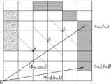
도 8은 마스터 작업 로봇과 슬레이브 작업 로봇의 상대적 위치를 통해 슬레이브 작업 로봇의 위치를 산출하는 방법을 예시적으로 나타내는 도면이다.FIG. 8 is a drawing exemplarily showing a method for calculating the position of a slave task robot through the relative positions of a master task robot and a slave task robot.
도 8을 참조하면, 마스터 작업 로봇(M)과 슬레이브 작업 로봇(S)이 도시되며, d는 마스터 작업 로봇(M)과 슬레이브 작업 로봇(S) 사이의 거리를 의미하고, l은 마스터 작업 로봇(M)과 슬레이브 작업 로봇(S)이 상기 작업 대상 공간의 특정 벽면 사이에서 형성하는 거리의 차이를 의미한다. 즉, l=lm-ls의 관계가 성립하고, lm은 마스터 작업 로봇(M)이 상기 특정 벽면에서 떨어진 거리를 의미하고, ls는 슬레이브 작업 로봇(S)이 상기 특정 벽면에서 떨어진 거리를 의미한다. 그리고, θ는 마스터 작업 로봇(M)과 슬레이브 작업 로봇(S) 사이의 각도를 의미한다.Referring to FIG. 8, a master task robot (M) and a slave task robot (S) are illustrated, d denotes a distance between the master task robot (M) and the slave task robot (S), and l denotes a difference in distance formed between the master task robot (M) and the slave task robot (S) and a specific wall surface of the work target space. That is, a relationship of l = lm -ls is established, and lm denotes a distance that the master task robot (M) is separated from the specific wall surface, and ls denotes a distance that the slave task robot (S) is separated from the specific wall surface. In addition, θ denotes an angle between the master task robot (M) and the slave task robot (S).
마스터 작업 로봇(M)은 센서를 이용하여 상기 벽면까지의 거리인 lm을 측정할 수 있고, 슬레이브 작업 로봇(S)은 도 3을 참조로 하여 설명한 거리 측정부(22)를 이용하여 마스터 작업 로봇(M)까지의 거리 d와 상기 벽면까지의 거리 ls를 측정할 수 있다. 따라서, lm과 ls의 차이를 이용하여 거리 l을 산출하고, 거리 측정부(22)를 통해 측정된 거리 d를 이용하여 상기 각도 θ 값을 산출할 수 있다.The master task robot (M) can measure the distance lm to the wall using a sensor, and the slave task robot (S) can measure the distance d to the master task robot (M) and the distance ls to the wall using the distance measuring unit (22) described with reference to FIG. 3. Accordingly, the distance l can be calculated using the difference between lm and ls , and the angle θ value can be calculated using the distance d measured through the distance measuring unit (22).
슬레이브 작업 로봇(S)의 제2 위치 판단부는 상기 거리 d와 각도 θ, 그리고 제1 위치 판단부로부터 제공되는 마스터 작업 로봇(M)의 위치 정보를 이용하여 슬레이브 작업 로봇(S)의 위치를 판단할 수 있다. 따라서, 마스터 작업 로봇(M)에서 측정되는 상기 lm 값은 마스터 작업 로봇(M)의 위치 정보와 함께 상기 제2 위치 판단부에 제공되는 것으로 이해할 수 있다.The second position determination unit of the slave task robot (S) can determine the position of the slave task robot (S) using the distance d and the angle θ, and the position information of the master task robot (M) provided from the first position determination unit. Accordingly, it can be understood that the lm value measured by the master task robot (M) is provided to the second position determination unit together with the position information of the master task robot (M).
또는, 상기 제2 위치 판단부는 상기 제1 위치 판단부로부터 제공되는 마스터 작업 로봇(M)의 위치 정보에 포함되는 좌표와, 마스터 작업 로봇(M)과 슬레이브 작업 로봇(S)이 상기 작업 대상 공간에 존재하는 한 쌍의 벽면과 떨어진 거리를 이용하여 슬레이브 작업 로봇(S)의 위치를 판단할 수 있다. 이러한 경우에는 마스터 작업 로봇(M)과 슬레이브 작업 로봇(S) 사이의 거리 d 값을 측정하지 않더라도 슬레이브 작업 로봇(S)의 위치를 판단할 수 있다.Alternatively, the second position determination unit may determine the position of the slave task robot (S) by using the coordinates included in the position information of the master task robot (M) provided from the first position determination unit and the distance between the master task robot (M) and the slave task robot (S) and a pair of walls existing in the task target space. In this case, the position of the slave task robot (S) can be determined even without measuring the distance d value between the master task robot (M) and the slave task robot (S).
이때 lm과 ls는 각각 마스터 작업 로봇(M)과 슬레이브 작업 로봇(S)으로부터 측정된 벽면까지의 거리 중 가장 가까운 값으로 측정되는 것은 통상의 기술자에게 자명하다.At this time, it is obvious to a person skilled in the art that lm and ls are measured as the closest values among the distances to the wall measured from the master work robot (M) and the slave work robot (S), respectively.
도 9는 본 발명에 따른 자율 작업 시스템이 적용되는 작업 로봇의 구성을 예시적으로 나타내는 도면이다.Figure 9 is a drawing exemplarily showing the configuration of a work robot to which an autonomous work system according to the present invention is applied.
도 9를 참조하면, 상기 작업 로봇 특히 마스터 작업 로봇은 센서, 예를 들면 스캐닝 센서(Scanning Sensor)를 포함할 수 있다. 상기 작업 로봇은 도 9에 도시되는 구성, 예컨대 몸체의 양 측면에 배치되는 한 쌍의 바퀴를 이용하여 이동할 수 있다. 또한, 도 9에는 도시되어 있지 않지만, 상기 작업 로봇은 하부에 적어도 하나의 바퀴를 더 포함할 수 있으며, 이를 통해 균형을 유지할 수 있다. 그러나 반드시 이에 한정되는 것은 아니며, 상기 작업 로봇에 동력을 제공하여 임의의 위치로 이동 가능케 하는 어떠한 구성이라도 포함할 수 있다.Referring to FIG. 9, the work robot, particularly the master work robot, may include a sensor, for example, a scanning sensor. The work robot may be moved using a configuration illustrated in FIG. 9, for example, a pair of wheels arranged on both sides of the body. In addition, although not illustrated in FIG. 9, the work robot may further include at least one wheel at the bottom, thereby maintaining balance. However, the present invention is not necessarily limited thereto, and any configuration that provides power to the work robot to enable it to move to an arbitrary location may be included.
예를 들어, 상기 작업 로봇은 드론(drone)과 같이 비행 가능하게 구성될 수 있으며, 복수 쌍의 구동장치를 통해 구성될 수도 있다. 또한, 수중에서도 이동 및 작업 수행이 가능하도록 구성될 수 있다. 또는, 사람이나 동물의 다리를 모방한 구조를 통해 이동 가능하게 구성될 수도 있다.For example, the above-mentioned work robot may be configured to be able to fly like a drone, and may be configured with multiple pairs of actuators. In addition, it may be configured to be able to move and perform tasks underwater. Alternatively, it may be configured to be able to move through a structure that imitates the legs of a human or animal.
도 2를 참조로 하여 설명한 바와 같이, 상기 센서를 통해 상기 마스터 작업 로봇의 위치를 판단할 수 있으므로 상기 마스터 작업 로봇의 위치는 상기 센서의 위치와 실질적으로 동일한 것으로 이해할 수 있다. 그러나 반드시 이에 한정되는 것은 아니고, 마스터 작업 로봇의 작업부 위치를 마스터 작업 로봇의 위치로 정의할 수 있으며, 센서의 위치와 작업부 위치 사이의 미리 정해진 위치 차이를 이용하여 작업부 위치를 정확히 보정할 수 있다. 이하 본 명세서에서는 편의 상 센서의 위치와 마스터 작업 로봇의 위치가 실질적으로 동일한 것으로 본다.As described with reference to FIG. 2, since the position of the master task robot can be determined through the sensor, the position of the master task robot can be understood as being substantially the same as the position of the sensor. However, it is not necessarily limited thereto, and the position of the work part of the master task robot can be defined as the position of the master task robot, and the position of the work part can be accurately corrected using a predetermined position difference between the position of the sensor and the position of the work part. In the following specification, for convenience, the position of the sensor and the position of the master task robot are considered to be substantially the same.
상기 작업 로봇의 위치는 (px, py)의 좌표로 표현될 수 있으며 모터에 의해 회전 가능하다. 그리고, 상기 센서의 회전 방향은 필요에 따라 다양하게 제어될 수 있다. 이때, 상기 센서의 각도는 도 9의 x축을 기준으로 표현될 수 있으며, 상기 센서에 의해 검출되는 물체의 위치는 (θL, d)의 극좌표로 표현될 수 있다. 여기서 d는 검출된 물체까지의 거리를 의미한다.The position of the above-mentioned working robot can be expressed by the coordinates of (px , py ) and can be rotated by the motor. In addition, the rotation direction of the sensor can be controlled in various ways as needed. At this time, the angle of the sensor can be expressed based on the x-axis of Fig. 9, and the position of the object detected by the sensor can be expressed by the polar coordinates of (θL , d). Here, d means the distance to the detected object.
한편, 상기 마스터 작업 로봇은 마킹 유닛(미도시)을 포함할 수 있다. 상기 마킹 유닛은 도 2를 참조로 하여 설명한 데이터 수신부(11)가 수신하는 상기 작업 대상 공간에 대응하는 정보에 포함되는 마킹 데이터에 대응하는 작업을 수행하기 위하여 상하, 좌우를 비롯하여 자유롭게 이동할 수 있도록 구비될 수 있으며 마킹 데이터에 대응하여 작업면의 특정 위치에서 일정한 표시를 하거나 이동 경로 상에 선(line)을 그리는 동작을 수행할 수 있다.Meanwhile, the master work robot may include a marking unit (not shown). The marking unit may be provided to freely move up and down, left and right, etc., in order to perform a task corresponding to marking data included in information corresponding to the work target space received by the data receiving unit (11) described with reference to Fig. 2, and may perform an action of making a certain mark at a specific location on the work surface or drawing a line on the movement path corresponding to the marking data.
도 10은 마스터 작업 로봇의 위치를 판단하기 위해 기준 맵 데이터와 센싱 데이터를 비교하는 데이터 변환 과정을 예시적으로 나타내는 도면이다.Figure 10 is a diagram exemplifying a data conversion process for comparing reference map data and sensing data to determine the position of a master task robot.
도 10을 참조하면, 상기 기준 맵 데이터는 그리드(Grid) 형식으로 표시될 수 있으며 다른 격자 영역에 비하여 어둡게 표시된 부분은 레이저 센서의 스캔 신호를 반사하는 물체가 있음을 나타낸다. 각각의 격자 영역은 (xm,i, ym,i), (xm,l, ym,l)과 같은 좌표 형식으로 표시될 수 있다.Referring to Fig. 10, the reference map data can be displayed in a grid format, and a darkened area compared to other grid areas indicates that there is an object reflecting the scan signal of the laser sensor. Each grid area can be displayed in a coordinate format such as (xm,i , ym,i ), (xm,l, y m,l ).
도 2를 참조로 하여 설명한, 본 발명의 일 실시예에 따른 제1 위치 판단부(14)는 마스터 작업 로봇(10)의 위치를 판단하기 위해 상기 기준 맵 데이터와 센싱 데이터를 비교하는 동작을 수행하는데, 그리드 데이터를 포함하는 상기 기준 맵 데이터와는 달리 상기 센싱 데이터는 물체까지의 거리 및 각도에 관한 데이터를 포함한다. 따라서, 제1 위치 판단부(14)는 상기 기준 맵 데이터와 상기 센싱 데이터를 비교하기 위해 그리드 형식의 상기 기준 맵 데이터를 거리와 각도에 관한 데이터로 변환할 수 있다.The first position determination unit (14) according to one embodiment of the present invention, described with reference to FIG. 2, performs an operation of comparing the reference map data and the sensing data to determine the position of the master task robot (10). Unlike the reference map data including grid data, the sensing data includes data regarding the distance and angle to an object. Therefore, the first position determination unit (14) can convert the reference map data in grid format into data regarding the distance and angle in order to compare the reference map data and the sensing data.
도 10을 참조하면, 상기 기준 맵 데이터에서 (xm,i, ym,i) 및 (xm,l, ym,l)의 좌표로 표현되는 위치는, 각각 (Φm,i,dm,i) 및 (Φm,l,dm,l)의 극좌표 형식의 데이터로 변환될 수 있으며 상기 극좌표 데이터는 상기 센싱 데이터의 데이터 형식과 일치한다. 따라서, 제1 위치 판단부(14)는 변환된 상기 기준 맵 데이터와 상기 센싱 데이터를 직접 비교할 수 있으며, 비교 결과를 이용하여 마스터 작업 로봇(10)의 위치를 판단할 수 있다.Referring to FIG. 10, the positions expressed by the coordinates (xm,i , ym,i ) and (xm,l , ym,l ) in the reference map data can be converted into data in the polar coordinate format of (Φm,i ,dm,i ) and (Φm,l ,dm,l ), respectively, and the polar coordinate data matches the data format of the sensing data. Therefore, the first position determination unit (14) can directly compare the converted reference map data with the sensing data, and can determine the position of the master task robot (10) using the comparison result.
다만, 상기 기준 맵 데이터와 상기 센싱 데이터가 각각 그리드 형식과 극좌표 형식으로 제한되는 것은 아니며, 두 종류의 데이터를 비교하기 위하여 반드시 그리드 형식의 데이터를 극좌표 형식으로 변환하는 것으로 제한되지 않는다. 따라서, 상기 기준 맵 데이터와 상기 센싱 데이터는 그리드 형식, 극좌표 형식 이외의 형태의 데이터로 표현될 수 있으며, 상기 센싱 데이터를 상기 기준 맵 데이터의 형식에 대응하도록 변환하여 두 종류의 데이터를 비교하는 것도 가능하다.However, the above-mentioned reference map data and the above-mentioned sensing data are not limited to the grid format and the polar coordinate format, respectively, and the comparison of the two types of data is not necessarily limited to converting the grid format data into the polar coordinate format. Accordingly, the above-mentioned reference map data and the above-mentioned sensing data may be expressed as data in a format other than the grid format and the polar coordinate format, and it is also possible to compare the two types of data by converting the sensing data to correspond to the format of the above-mentioned reference map data.
도 10에서 복수의 격자 영역은 디스플레이 장치를 통해 표현되는 경우에 있어서 각각의 화소(pixel)에 대응하는 것으로 이해할 수 있으나, 반드시 이에 한정되는 것은 아니며, 하나의 격자 영역이 복수의 화소 집합체에 대응하는 것일 수 있다. 극좌표 변환을 위한 기준점은 도 9에 도시되는 바와 같이 반드시 원점(0)으로 제한되지 않는다.In Fig. 10, it can be understood that the plurality of grid areas correspond to each pixel when expressed through a display device, but it is not necessarily limited to this, and one grid area may correspond to a plurality of pixel groups. The reference point for polar coordinate transformation is not necessarily limited to the origin (0) as illustrated in Fig. 9.
한편, 센싱부(12)에서 상기 작업 대상 공간에 존재하는 물체에 대한 센싱 데이터가 획득되면, 제1 위치 판단부(14)는 상기 센싱 데이터에 대응하는 거리/각도 데이터와 변환된 상기 기준 맵 데이터를 비교하여 일치하는 데이터가 존재하는지 판단할 수 있다.Meanwhile, when sensing data for an object existing in the work target space is acquired from the sensing unit (12), the first position determination unit (14) can compare the distance/angle data corresponding to the sensing data with the converted reference map data to determine whether matching data exists.
상기 판단 결과에 따라 일치하는 데이터가 여러 개 존재할 수 있으며, 제1 위치 판단부(14)는 복수의 센싱 데이터와 변환된 상기 기준 맵 데이터를 비교하여 상기 이동체에 대한 위치 판단의 정확도를 향상시킬 수 있다.Depending on the above judgment result, there may be multiple matching data, and the first location judgment unit (14) can compare multiple sensing data with the converted reference map data to improve the accuracy of location judgment for the moving object.
제1 위치 판단부(14)는 복수의 센싱 데이터 각각을 상기 기준 맵 데이터와 비교함으로써 상기 이동체의 위치로서 가장 신뢰성이 높은 위치를 판단할 수 있다.The first position determination unit (14) can determine the most reliable location as the location of the moving object by comparing each of the plurality of sensing data with the reference map data.
예를 들어, 동일한 위치에서 상기 센서를 이용하여 제1 내지 제n 센싱 데이터가 획득되면, 제1 위치 판단부(14)는 상기 제1 센싱 데이터에 대응하는 기준 맵 데이터를 검색할 수 있다. 검색 결과 상기 제1 센싱 데이터에 대응하는 기준 맵 데이터가 m개 존재할 수 있으며, 제1 위치 판단부(14)는 상기 제2 센싱 데이터와 상기 m개의 기준 맵 데이터를 비교하게 된다. 이러한 과정을 반복 수행하게 되면 최종적으로 상기 제1 내지 제n 센싱 데이터를 획득한 위치, 즉 마스터 작업 로봇(10)의 위치를 검출할 수 있게 된다.For example, when the first to nth sensing data are acquired using the sensor at the same location, the first location determination unit (14) can search for reference map data corresponding to the first sensing data. As a result of the search, there may be m reference map data corresponding to the first sensing data, and the first location determination unit (14) compares the second sensing data with the m reference map data. By repeating this process, the location where the first to nth sensing data were acquired, i.e., the location of the master work robot (10), can be detected.
한편, 기준 맵 데이터와 센싱 데이터를 비교하여 마스터 작업 로봇(10)의 위치를 검출하기 위해서, 제1 위치 판단부(14)는 가장 최근에 획득된 센싱 데이터를 이용할 수 있다.Meanwhile, in order to detect the position of the master work robot (10) by comparing the reference map data and the sensing data, the first position determination unit (14) can use the most recently acquired sensing data.
도 10에서 위치 a, b, c는 마스터 작업 로봇(10)의 이동 경로 상에 존재하는 일부 위치를 예시적으로 나타내며, 마스터 작업 로봇(10)이 위치 a에서 위치 c 방향으로 이동하고 센서는 위치 a에서 위치 c를 향하는 방향을 바라보는 경우를 상정하여 설명하도록 한다.In Fig. 10, positions a, b, and c exemplarily represent some positions existing on the movement path of the master task robot (10), and the description will assume a case where the master task robot (10) moves from position a to position c and the sensor looks in the direction from position a to position c.
상기 센서는 위치 a, b 및 c에서 센싱 동작, 예를 들면 스캐닝 동작을 수행하여 센싱 데이터를 획득할 수 있는데, 상기 센서가 제한된 범위만을 센싱할 수 있는 경우, 예컨대, 상기 센서가 전방을 기준으로 ±90°로 총 180° 범위를 센싱 가능한 경우, 도 10을 참조하면 각각의 위치 a, b 및 c에서 상기 센서를 통해 획득되는 센싱 데이터의 데이터량은 서로 차이가 발생할 수 있다.The above sensor can obtain sensing data by performing a sensing operation, for example, a scanning operation, at locations a, b, and c. However, if the sensor can sense only a limited range, for example, if the sensor can sense a total range of 180° at ±90° with respect to the front, the data amounts of sensing data obtained through the sensor at each of locations a, b, and c may differ from each other as shown in FIG. 10.
예컨대, 위치 a에서 획득되는 센싱 데이터의 데이터량은 위치 c에서 획득되는 센싱 데이터의 데이터량 보다 많을 수 있다. 이때, 마스터 작업 로봇(10)이 위치 c에 존재할 때 기준 맵 데이터와 센싱 데이터를 비교하여 마스터 작업 로봇(10)의 위치를 검출함에 있어서, 제1 위치 판단부(14)는 위치 b에서 획득된 센싱 데이터와 상기 기준 맵 데이터를 비교할 수 있다.For example, the amount of data of sensing data acquired at location a may be greater than the amount of data of sensing data acquired at location c. At this time, when the master task robot (10) is present at location c, in detecting the position of the master task robot (10) by comparing the sensing data with the reference map data, the first position determination unit (14) may compare the sensing data acquired at location b with the reference map data.
위치 a에서 획득되는 센싱 데이터는 위치 b에서 획득된 센싱 데이터보다 많은 양의 데이터를 포함하게 되므로, 위치 b에서 획득된 센싱 데이터와 상기 기준 맵 데이터를 비교함으로써 연산 속도를 빠르게 할 수 있다.Since the sensing data acquired at location a includes a larger amount of data than the sensing data acquired at location b, the computation speed can be increased by comparing the sensing data acquired at location b with the reference map data.
센서는 연속적으로 센싱, 예를 들면 스캐닝을 수행함으로써 센싱 데이터를 획득하고, 제1 위치 판단부(14)는 상기 센싱 데이터를 이용하여 연속적으로 마스터 작업 로봇(10)의 정확한 위치를 검출할 수 있으므로, 현재 시점에서 가장 가까운 시점에 획득된 데이터를 이용하는 것이 위치 검출의 정확도를 향상시키는 방법이 될 수 있다.The sensor acquires sensing data by performing continuous sensing, for example, scanning, and the first position determination unit (14) can continuously detect the exact position of the master work robot (10) using the sensing data. Therefore, using the data acquired at the closest point in time to the current point in time can be a method for improving the accuracy of position detection.
도 11은 본 발명의 일 실시예에 따른 마스터 작업 로봇의 이동경로를 예시적으로 나타내는 도면이다.FIG. 11 is a drawing exemplarily showing a movement path of a master task robot according to one embodiment of the present invention.
상기 마스터 작업 로봇의 이동경로는 적어도 하나의 센싱 위치 및 센서의 센싱 각도에 관한 정보를 포함할 수 있다. 도 11에 도시된 실시예를 참조하면, 상기 마스터 작업 로봇은 제1 지점(x1, y1, θ1) 내지 제7 지점(x7, y7, θ7)에서 상기 센서를 이용하여 센싱 동작, 예를 들면 스캐닝 동작을 수행한다.The movement path of the above master task robot may include information about at least one sensing position and a sensing angle of the sensor. Referring to the embodiment illustrated in Fig. 11, the master task robot performs a sensing operation, for example, a scanning operation, using the sensor at a first point (x1, y1, θ1) to a seventh point (x7, y7, θ7).
도 11에서는 상기 마스터 작업 로봇이 센싱 동작을 수행하는 특정한 몇 개의 센싱 위치를 도시하고 있으며, 이는 상기 마스터 작업 로봇의 위치를 정확하게 파악하기 위함이다.Figure 11 illustrates several specific sensing positions at which the master task robot performs sensing operations, in order to accurately determine the position of the master task robot.
그러나, 본 발명의 다른 실시예에 따른 마스터 작업 로봇은 특정한 센싱 위치를 지정하지 않고 설정된 상기 이동경로를 따라 이동하면서 연속적으로 센싱 동작을 수행할 수 있다.However, a master task robot according to another embodiment of the present invention can perform sensing operations continuously while moving along a set movement path without specifying a specific sensing position.
한편, 상기 센싱 각도는 각각의 센싱 위치에서 상기 센서의 센싱 각도를 의미하며 Degree 또는 Radian 단위로 표현 가능하다. 그리고, 상기 센싱 각도의 크기는 x축을 기준으로 표현되거나, 직전 센싱 위치에서의 센싱 동작이 종료된 시점에서의 상기 센서의 각도를 기준으로 표현될 수 있다.Meanwhile, the sensing angle refers to the sensing angle of the sensor at each sensing position and can be expressed in units of Degree or Radian. In addition, the size of the sensing angle can be expressed based on the x-axis or based on the angle of the sensor at the point in time when the sensing operation at the previous sensing position is finished.
각각의 상기 센싱 위치에서 상기 마스터 작업 로봇은 정지하며, 상기 센싱 위치에 정지한 상태에서 상기 센서를 회전시켜 주변 공간을 센싱 한다. 다만, 앞서 설명한 바와 같이 상기 마스터 작업 로봇은 특정한 센싱 위치를 지정하지 않고 설정된 상기 이동경로를 따라 이동하면서 연속적으로 센싱 동작을 수행할 수 있다. 따라서, 이러한 경우에는 상기 센싱 위치에서 정지하는 동작이 수행되지 않는 것으로 이해할 수 있다.At each of the sensing positions, the master work robot stops, and while stopped at the sensing position, rotates the sensor to sense the surrounding space. However, as described above, the master work robot can perform the sensing operation continuously while moving along the set movement path without designating a specific sensing position. Therefore, in this case, it can be understood that the operation of stopping at the sensing position is not performed.
또한, 상기 센싱 동작을 통해 획득되는 센싱 데이터와 상기 기준 맵 데이터를 비교함으로써 상기 마스터 작업 로봇의 위치가 상기 이동 경로에 일치하는지 여부를 판단할 수 있다.In addition, by comparing the sensing data obtained through the sensing operation with the reference map data, it is possible to determine whether the position of the master task robot matches the movement path.
따라서, 본 발명의 일 실시예에 따른 자율 작업 시스템을 통해 상기 마스터 작업 로봇은 설정된 이동 경로를 따라 이동하며 마킹 데이터에 따라 해당하는 위치에서 특정한 표시를 하거나 선(line)을 그리는 동작을 수행할 수 있다.Accordingly, through the autonomous work system according to one embodiment of the present invention, the master work robot can move along a set movement path and perform an action of making a specific mark or drawing a line at a corresponding location according to marking data.
또한, 이와 동시에 복수의 센싱 위치에서 센서를 통한 센싱 동작을 통해 스스로의 위치와 미리 설정된 상기 이동 경로와의 일치 여부를 판단하고, 상기 이동 경로와 일치하지 않는 경우에는 상기 이동 경로를 따라 이동하도록 위치가 제어될 수 있다.In addition, at the same time, the sensing operation using the sensor at multiple sensing locations can be used to determine whether its own location matches the preset movement path, and if it does not match the movement path, the location can be controlled to move along the movement path.
한편, 도 11에는 총 7개의 스캔 위치가 도시되어 있으나, 본 발명이 반드시 상기 7개의 센싱 위치로 제한되지 않으며 상기 센싱 위치는 상기 센싱 대상 공간에 존재하는 기둥, 유리창, 장애물 등의 위치에 의하여 다양하게 변경될 수 있다. 또한, 상기 센싱 대상 공간 내에 비어있는 공간이 존재하는 경우에는 상기 비어있는 공간에서는 센싱이 어려울 수 있으므로 상기 복수의 센싱 위치와 센싱 각도는 상기 비어있는 공간의 위치를 고려하여 설정될 수 있다.Meanwhile, although a total of 7 scan locations are illustrated in FIG. 11, the present invention is not necessarily limited to the 7 sensing locations, and the sensing locations may be variously changed depending on the locations of pillars, windows, obstacles, etc. existing in the sensing target space. In addition, if there is an empty space within the sensing target space, sensing may be difficult in the empty space, and therefore the plurality of sensing locations and sensing angles may be set in consideration of the location of the empty space.
도 12는 본 발명의 일 실시예에 따른 마스터 작업 로봇을 통해 획득되는 기준 맵을 예시적으로 나타내는 도면이다.FIG. 12 is a drawing exemplarily showing a reference map acquired through a master task robot according to one embodiment of the present invention.
도 12는 기준위치(reference)에서 센서를 통해 획득한 센싱 데이터를 통해 획득한 기준 맵(Reference Map)을 나타내며, 유리창(glass)이 존재하는 위치에서는 스캔 신호의 반사가 일어나지 않아 상기 유리창(glass)의 위치에서부터 상기 기준위치(reference)까지 정상적인 센싱 데이터가 획득되지 않는 것을 확인할 수 있다.Figure 12 shows a reference map obtained through sensing data acquired through a sensor at a reference position. It can be confirmed that no reflection of the scan signal occurs at a location where a glass window exists, and therefore, normal sensing data is not acquired from the location of the glass window to the reference position.
또한, 기둥(pillar)의 뒷 공간으로부터는 센싱 데이터가 정상적으로 획득되지 않음을 확인할 수 있다. 따라서, 상기 센서를 통해 획득되는 상기 센싱 데이터를 통해 상기 기준 맵을 생성하면 센싱 대상 공간에서 유리창이 존재하는 위치와 기둥 또는 장애물이 존재하는 위치를 대략적으로 판단할 수 있다.In addition, it can be confirmed that sensing data is not normally acquired from the space behind the pillar. Therefore, by generating the reference map using the sensing data acquired through the sensor, it is possible to roughly determine the location where the glass window exists and the location where the pillar or obstacle exists in the sensing target space.
한편, 정지상태의 센서를 회전시켜 획득한 센싱 데이터를 이용하여 상기 기준 맵을 생성하는 경우에는 센싱 대상 공간의 크기에 따라 스캔 거리가 길어지고, 이에 따라 정확도가 떨어질 수 있으며, 따라서 상기 기준 맵은 상기 마스터 작업 로봇의 이동 경로, 센싱 위치 및 센싱 각도를 설정하는데에 참고 데이터로 활용하는 것이 바람직하다.Meanwhile, when the reference map is created using sensing data acquired by rotating a stationary sensor, the scan distance may become longer depending on the size of the sensing target space, and thus the accuracy may decrease. Therefore, it is preferable to use the reference map as reference data for setting the movement path, sensing position, and sensing angle of the master work robot.
또한, 상기 작업 대상 공간에 대한 도면이 존재하는 경우에는 상기 도면과 상기 기준 맵을 함께 사용하는 것이 상기 마스터 작업 로봇의 보다 정확한 동작을 구현하는데 도움이 될 수 있다.Additionally, if a drawing of the work target space exists, using the drawing and the reference map together can help implement more accurate movements of the master work robot.
한편, 상기 마스터 작업 로봇의 이동 경로, 센싱 위치 및 센싱 각도는 상기 센싱 대상 공간에 대한 정확한 센싱 데이터를 획득할 수 있도록 설정되며, 도 9에서는 상기 기준위치(reference)를 포함하여 유리창(glass)과 기둥(pillar)에서 최대한 이격되는 위치와 각도가 설정될 수 있다.Meanwhile, the movement path, sensing position and sensing angle of the master task robot are set so as to obtain accurate sensing data for the sensing target space, and in Fig. 9, the position and angle that are as far away from the glass and pillar as possible, including the reference position, can be set.
도 13은 본 발명의 일 실시예에 따른 자율 작업 방법을 개략적으로 나타내는 도면이다.FIG. 13 is a drawing schematically illustrating an autonomous working method according to one embodiment of the present invention.
본 발명의 일 실시예에 따른 자율 작업 방법은, 마스터 작업 로봇 및 적어도 하나의 슬레이브 작업 로봇을 포함하는 자율 작업 시스템을 이용하는 자율 작업 방법으로서, 도 13을 참조하면 정보 수신 단계(S10), 센싱 설정 단계(S20), 마스터 위치 판단 단계(S30) 및 슬레이브 위치 판단 단계(S40)를 포함한다.An autonomous working method according to one embodiment of the present invention is an autonomous working method using an autonomous working system including a master working robot and at least one slave working robot, and includes an information receiving step (S10), a sensing setting step (S20), a master position determination step (S30), and a slave position determination step (S40) as shown in FIG. 13.
정보 수신 단계(S10)에서는 작업 대상 공간에 대한 정보를 수신한다. 상기 작업 대상 공간은 상기 마스터 작업 로봇 및 슬레이브 작업 로봇이 작업을 수행하는 공간을 의미하며, 정보 수신 단계(S10)에서 수신되는 정보는 상기 작업 대상 공간에 대응하는 도면, 상기 작업 대상 공간에 존재하는 벽, 기둥, 창문 등의 위치와 크기에 관한 정보, 요컨대 상기 작업 대상 공간의 건축적, 공간적 요소에 관한 정보를 포함할 수 있다. 또한, 정보 수신 단계(S10)에서는 상기 마스터 작업 로봇과 슬레이브 작업 로봇이 상기 작업 대상 공간에서 수행해야 하는 작업(task)에 관한 정보를 수신할 수 있다.In the information receiving step (S10), information about a work target space is received. The work target space refers to a space where the master work robot and the slave work robot perform work, and the information received in the information receiving step (S10) may include a drawing corresponding to the work target space, information about the location and size of walls, pillars, windows, etc. existing in the work target space, and in short, information about architectural and spatial elements of the work target space. In addition, in the information receiving step (S10), the master work robot and the slave work robot may receive information about a task to be performed in the work target space.
한편, 상기 작업 대상 공간에 대한 정보는 상기 마스터 작업 로봇 및 슬레이브 작업 로봇의 허용 이동 범위에 관한 정보를 포함할 수 있다. 예컨대, 상기 작업 대상 공간은 벽, 기둥, 창문 등이 설치되어야 하는 공간을 포함할 수 있으며, 설치 이전에는 상기 마스터 작업 로봇 및 슬레이브 작업 로봇으로 하여금 진입하지 못하도록 방지해야 하는 공간이 존재할 수 있다. 벽이 세워지거나, 엘리베이터가 설치되어야 하는 공간은 실제 작업이 이루어지기 전에는 바닥면이 단절되어 있을 수 있으며, 경우에 따라서는 상기 마스터 작업 로봇 및 슬레이브 작업 로봇이 추락할 위험이 있을 수 있다. 따라서, 상기 작업 대상 공간에 대한 정보는 상기 허용 이동 범위에 관한 정보를 포함하여, 상기 마스터 작업 로봇 및 슬레이브 작업 로봇의 이동 범위를 제한하도록 할 수 있다. 또한 상기 작업 대상 공간에 대한 정보는 특정 포인트, 예컨대 벽이나 기둥의 중심 위치가 표시된 것일 수 있다. 이러한 특정 포인트는 마스터 작업 로봇 및/또는 슬레이브 작업 로봇의 이동 및/또는 작업 시 기준점으로 활용될 수 있다.Meanwhile, the information about the work target space may include information about the allowable movement range of the master work robot and the slave work robot. For example, the work target space may include a space where a wall, a pillar, a window, etc. are to be installed, and there may be a space where the master work robot and the slave work robot must be prevented from entering before installation. A space where a wall is to be built or an elevator is to be installed may have a floor that is disconnected before actual work is performed, and in some cases, there may be a risk of the master work robot and the slave work robot falling. Therefore, the information about the work target space may include information about the allowable movement range to limit the movement range of the master work robot and the slave work robot. In addition, the information about the work target space may indicate a specific point, such as the center position of a wall or a pillar. This specific point may be utilized as a reference point when the master work robot and/or the slave work robot moves and/or works.
정보 수신 단계(S10)에서는 상기 마스터 작업 로봇에 포함되는 센서와 유선 또는 무선, 전기적 또는 비전기적으로 연결되어 상기 센서로부터 획득되는 데이터를 수신할 수 있다. 또한, 정보 수신 단계(S10)에서는 외부 저장매체에 저장된 상기 작업 대상 공간에 대한 데이터를 수신할 수도 있다. 선택적으로, 정보 수신 단계(S10)에서는 마스터 작업 로봇의 입력부로부터 입력되는 상기 작업 대상 공간에 대한 데이터를 수신할 수 있다. 선택적으로, 정보 수신 단계(S10)에서는 마스터 작업 로봇이 별도의 컴퓨팅 장치와 전기적으로 연결되어 컴퓨팅 장치로부터 상기 작업 대상 공간에 대한 데이터를 수신할 수 있다.In the information receiving step (S10), the master task robot may be connected to a sensor included in the master task robot by wire or wirelessly, electrically or non-electrically, to receive data acquired from the sensor. In addition, in the information receiving step (S10), data on the task target space stored in an external storage medium may also be received. Optionally, in the information receiving step (S10), data on the task target space input from the input unit of the master task robot may be received. Optionally, in the information receiving step (S10), the master task robot may be electrically connected to a separate computing device to receive data on the task target space from the computing device.
한편, 상기 센서는 사물까지의 거리를 측정하거나 사물의 형태를 센싱하거나 마스터 작업 로봇의 이동을 센싱할 수 있다. 이러한 센서는, 레이저를 이용하거나 음파, 광파 및/또는 전파를 이용하는 센서, IMU 센서, GPS 센서를 포함할 수 있으며, 및/또는 카메라와 같이 동영상 및/또는 정지 영상를 취득할 수 있는 영상 취득 센서를 포함할 수 있다. 상기 센서가 레이저 센서를 포함하는 경우 상기 레이저 센서의 일 예로서 라이더(LiDAR) 센서가 포함될 수 있다.Meanwhile, the sensor may measure the distance to an object, sense the shape of an object, or sense the movement of the master task robot. Such a sensor may include a sensor using a laser, a sensor using sound waves, light waves, and/or radio waves, an IMU sensor, a GPS sensor, and/or an image acquisition sensor capable of acquiring a video and/or still image, such as a camera. When the sensor includes a laser sensor, an example of the laser sensor may include a LiDAR sensor.
마스터 작업 로봇은 이러한 센서를 적어도 하나 이상 포함할 수 있으며, 다른 종류의 복수의 센서를 조합함으로써 센싱 정밀도를 향상시킬 수 있다. 예컨대 레이저 센서로서 라이더 센서를 사용하고, IMU 센서를 더 포함해 마스터 작업 로봇의 움직임을 센싱함으로써 작업 대상 공간에 대한 센싱 정밀도를 향상시킬 수 있다. 또한, 선택적 및/또는 부가적으로 카메라 센서를 포함해, 카메라 센서로 하여금 작업 대상 공간을 촬영하도록 할 수 있는 데, 예컨대 작업 대상 공간의 특정 면, 구체적으로 바닥면에 대한 상태 및/또는 질감을 촬영하고 이를 통해 마스터 작업 로봇 및/또는 슬레이브 작업 로봇의 이동 및/또는 작업 경로를 설정 및/또는 보정하도록 할 수 있다. 또한, 선택적 및/또는 부가적으로 거리 측정 센서를 포함해, 특정 포인트, 예컨대 벽이나 기둥까지의 거리를 측정할 수 있다. 이로 인해 상기 작업 대상 공간에 존재하는 특정 포인트의 계측된 위치를 마스터 작업 로봇 및/또는 슬레이브 작업 로봇의 이동 및/또는 작업 경로를 설정 및/또는 보정하는 데에 반영하도록 할 수 있다. 상기와 같은 다양한 센서 조합은 반드시 마스터 작업 로봇에만 설치될 필요는 없으며, 일부 센서는 슬레이브 작업 로봇에 설치되고, 그 데이터가 마스터 작업 로봇과 통신되도록 함으로써 작업 전 및/또는 작업 도중에 마스터 작업 로봇 및/또는 슬레이브 작업 로봇의 이동 및/또는 작업 경로를 설정 및/또는 보정하도록 할 수 있다.The master task robot may include at least one of these sensors, and may improve the sensing precision by combining multiple sensors of different types. For example, a lidar sensor may be used as a laser sensor, and an IMU sensor may be further included to sense the movement of the master task robot, thereby improving the sensing precision for the task target space. In addition, a camera sensor may be optionally and/or additionally included, so that the camera sensor may photograph the task target space, for example, photograph the condition and/or texture of a specific surface of the task target space, specifically, a floor surface, and thereby set and/or correct the movement and/or work path of the master task robot and/or the slave task robot. In addition, a distance measurement sensor may be optionally and/or additionally included, so as to measure the distance to a specific point, for example, a wall or a pillar. As a result, the measured position of a specific point existing in the task target space may be reflected in setting and/or correcting the movement and/or work path of the master task robot and/or the slave task robot. The above-described various sensor combinations do not necessarily have to be installed only in the master task robot, and some sensors may be installed in the slave task robots, and their data may be communicated to the master task robot, thereby enabling the movement and/or task path of the master task robot and/or the slave task robot to be set and/or corrected before and/or during the task.
상기 마스터 작업 로봇은 정지 상태에서 및/또는 이동하면서 상기 센서를 이용하여 주변 공간을 센싱할 수 있으며, 상기 센서에서 출력된 신호가 반사되는 정보를 이용하여 주변 공간에 있는 사물의 위치를 극좌표 형식으로 획득할 수 있다. 상기 모터는 상기 센서를 원하는 각도만큼 회전할 수 있도록 하며, 예컨대 360˚ 회전할 수 있도록 하며, 상기 센서의 회전 방향은 필요에 따라 다양하게 제어될 수 있다.The above master task robot can sense the surrounding space using the sensor while stationary and/or moving, and can obtain the location of an object in the surrounding space in polar coordinate format using information reflected from a signal output from the sensor. The motor can rotate the sensor by a desired angle, for example, 360˚, and the rotation direction of the sensor can be variously controlled as needed.
한편, 상기 센서는 별도의 구동부에 의하여 수평 회전, 수평 이동, 틸트 및/또는 수직 이동이 제어될 수 있다. 상기 센서의 수평 회전, 수평 이동, 틸트 및/또는 수직 이동은 서로 독립적으로 제어될 수 있으며, 상기 수평 회전, 수평 이동, 틸트 및/또는 수직 이동을 제어하기 위한 제어 신호 또한 독립적으로 생성되어 상기 구동부에 제공될 수 있다.Meanwhile, the sensor may be controlled for horizontal rotation, horizontal movement, tilt and/or vertical movement by a separate driving unit. The horizontal rotation, horizontal movement, tilt and/or vertical movement of the sensor may be controlled independently of each other, and a control signal for controlling the horizontal rotation, horizontal movement, tilt and/or vertical movement may also be independently generated and provided to the driving unit.
센싱 설정 단계(S20)에서는 상기 마스터 작업 로봇의 이동 경로, 센싱 위치 및 상기 센싱 위치에서의 센싱 각도를 설정한다. 구체적으로, 센싱 설정 단계(S20)에서는 상기 이동 경로를 설정하고, 상기 이동 경로 상의 임의의 지점을 지정하여 지정된 상기 지점을 센싱 위치로 설정한다. 그리고, 상기 센싱 위치는 상기 작업 대상 공간에 따라 필요한 경우 복수 개의 위치로 설정될 수 있다. 이에 대응하여 상기 마스터 작업 로봇이 상기 센싱 위치에 도달하면 상기 센서는 센싱 동작을 수행한다. 그리고 이때, 상기 센서는 센싱 설정 단계(S20)에서 의해 설정된 센싱 각도에 따라 회전하게 된다.In the sensing setting step (S20), the movement path of the master task robot, the sensing position, and the sensing angle at the sensing position are set. Specifically, in the sensing setting step (S20), the movement path is set, and an arbitrary point on the movement path is designated and the designated point is set as a sensing position. In addition, the sensing position can be set to a plurality of positions if necessary depending on the work target space. In response, when the master task robot reaches the sensing position, the sensor performs a sensing operation. In this case, the sensor rotates according to the sensing angle set by the sensing setting step (S20).
한편, 본 발명의 다른 실시예에서 상기 센서는 센싱 높이가 조절될 수 있으며, 센싱 설정 단계(S20)에서는 설정된 센싱 위치에서 상기 센서의 센싱 각도 및 센싱 높이를 함께 설정할 수 있다. 그리고, 상기 센싱 위치와 센싱 각도는 상기 작업 대상 공간의 특성을 고려하여 설정될 수 있다.Meanwhile, in another embodiment of the present invention, the sensor may have an adjustable sensing height, and in the sensing setting step (S20), the sensing angle and sensing height of the sensor may be set together at the set sensing position. In addition, the sensing position and sensing angle may be set in consideration of the characteristics of the work target space.
또한, 빛을 반사하지 않고 투과하는 등, 센싱 데이터를 획득하기 어려운 경우, 상기 센싱 위치와 센싱 각도는 상기 작업 대상 공간 내의 비어있는 공간에 배치되어 기둥이나 장애물 등을 센싱할 수 있는 위치와 각도로 설정될 수 있다.In addition, in cases where it is difficult to obtain sensing data, such as when light is transmitted rather than reflected, the sensing position and sensing angle may be set to a position and angle that can sense pillars or obstacles, etc., by being placed in an empty space within the work target space.
한편, 상기 작업 대상 공간의 도면이 존재하는 경우, 센싱 설정 단계(S20)에서는 상기 도면을 고려하여 상기 이동 경로, 센싱 위치 및 센싱 위치에서의 상기 센서의 센싱 각도를 설정할 수 있다.Meanwhile, if a drawing of the work target space exists, in the sensing setting step (S20), the movement path, sensing position, and sensing angle of the sensor at the sensing position can be set by considering the drawing.
상기 마스터 작업 로봇은 상기 이동 경로 상에서 특정한 위치에서 센싱 동작을 수행하는 것으로 이해할 수 있다. 그리고, 상기 특정한 센싱 위치가 지정되는 것은 상기 마스터 작업 로봇의 위치를 정확하게 파악하기 위함이다.It can be understood that the above master task robot performs a sensing operation at a specific location on the above movement path. In addition, the specific sensing location is designated to accurately determine the location of the master task robot.
상기 특정한 위치는 유한한 개수의 위치로 설정될 수 있으나, 반드시 이에 제한되는 것은 아니며 상기 이동 경로 상에서 이동하며 연속적으로 센싱 동작을 수행할 수도 있다.The above specific location may be set to a finite number of locations, but is not necessarily limited thereto, and may also perform sensing operations continuously while moving along the above movement path.
한편, 상기 센싱 각도는 각각의 센싱 위치에서 상기 센서의 센싱 각도를 의미하며 Degree 또는 Radian 단위로 표현 가능하다. 그리고, 상기 센싱 각도의 크기는 특정 좌표축, 예컨대 x축을 기준으로 표현되거나, 직전 센싱 위치에서의 센싱 동작이 종료된 시점에서의 상기 센서의 각도를 기준으로 표현될 수 있다.Meanwhile, the sensing angle refers to the sensing angle of the sensor at each sensing position and can be expressed in units of Degree or Radian. In addition, the size of the sensing angle can be expressed based on a specific coordinate axis, for example, the x-axis, or can be expressed based on the angle of the sensor at the point in time when the sensing operation at the previous sensing position is terminated.
이처럼 마스터 작업 로봇의 이동 경로, 센싱 위치 및 센싱부의 센싱 각도를 설정하도록 상기 센싱 설정 단계(S20)에서는 마스터 작업 로봇의 복수의 구동부에 동작 신호를 보낼 수 있다.In this way, in the sensing setting step (S20), an operation signal can be sent to multiple driving units of the master task robot to set the movement path of the master task robot, the sensing position, and the sensing angle of the sensing unit.
본 발명의 일 실시예에서, 각각의 상기 센싱 위치에서 상기 마스터 작업 로봇은 정지하며, 상기 센싱 위치에 정지한 상태에서 상기 센서를 회전시켜 주변 공간을 센싱 할 수 있다. 또는, 본 발명의 다른 실시예에서 상기 마스터 작업 로봇은 상기 센싱 위치에서 정지하지 않을 수 있으며, 이동하며 상기 센서를 통해 주변 공간을 센싱 할 수 있다.In one embodiment of the present invention, the master work robot may stop at each of the sensing positions and may sense the surrounding space by rotating the sensor while stopped at the sensing position. Alternatively, in another embodiment of the present invention, the master work robot may not stop at the sensing position, but may move and sense the surrounding space through the sensor.
마스터 위치 판단 단계(S30)에서는 상기 센싱 위치에서 획득된 센싱 데이터와 기준 맵 데이터를 비교하여 상기 마스터 작업 로봇의 위치를 판단한다.In the master position determination step (S30), the sensing data obtained at the sensing position is compared with the reference map data to determine the position of the master work robot.
상기 기준 맵 데이터는 이미지 프레임에 포함되는 픽셀의 좌표로 표현될 수 있으며, 물체가 존재하는 위치에 대응하는 픽셀의 좌표는 비어있는 위치에 대응하는 픽셀의 좌표와 다른 값을 가질 수 있다. 앞서 설명한 바와 같이, 상기 센서를 통해 획득되는 데이터는 극좌표 형태로 획득될 수 있으며 상기 기준 맵 데이터와 상기 센싱 데이터를 비교하면, 상기 작업 대상 공간 내에서의 상기 마스터 작업 로봇의 위치를 판단할 수 있다. 이 때, 전술한 바와 같이 기준 맵 데이터에 반영된 특정 포인트, 예컨대 벽이나 기둥의 중심과 센싱된 데이터를 비교할 수 있다.The above reference map data can be expressed as coordinates of pixels included in the image frame, and the coordinates of pixels corresponding to a location where an object exists can have different values from the coordinates of pixels corresponding to an empty location. As described above, the data acquired through the sensor can be acquired in the form of polar coordinates, and by comparing the reference map data and the sensed data, the position of the master work robot within the work target space can be determined. At this time, as described above, a specific point reflected in the reference map data, such as the center of a wall or pillar, can be compared with the sensed data.
보다 구체적으로, 마스터 위치 판단 단계(S30)에서는 상기 기준 맵 데이터를 상기 센서를 통해 획득되는 극좌표 형태의 데이터로 변환하고, 변환된 데이터와 상기 센싱 데이터를 비교할 수 있다.More specifically, in the master location determination step (S30), the reference map data can be converted into polar coordinate data obtained through the sensor, and the converted data can be compared with the sensing data.
본 발명의 다른 실시예에서, 마스터 위치 판단 단계(S30)에서는 임의의 위치에 설치되는 송수신기로부터 출력된 위치 신호를 수신하고, 상기 위치 신호로부터 상기 마스터 작업 로봇의 위치를 판단할 수 있다. 상기 송수신기의 위치가 결정되면 상기 마스터 위치 판단 단계(S30)에서는 송수신기의 위치를 기준으로 하여 상기 마스터 작업 로봇의 위치를 판단할 수 있다. 또는, 마스터 위치 판단 단계(S30)에서는 상기 마스터 작업 로봇으로부터 상기 송수신기까지의 거리, 각도 데이터 및 상기 송수신기의 위치 정보를 고려하여 상기 마스터 작업 로봇의 위치를 판단하는 것도 가능할 것이다.In another embodiment of the present invention, in the master position determination step (S30), a position signal output from a transceiver installed at an arbitrary location may be received, and the position of the master task robot may be determined from the position signal. Once the position of the transceiver is determined, in the master position determination step (S30), the position of the master task robot may be determined based on the position of the transceiver. Alternatively, in the master position determination step (S30), the position of the master task robot may be determined by considering the distance from the master task robot to the transceiver, angle data, and position information of the transceiver.
선택적으로, 마스터 위치 판단 단계(S30)에서는 임의의 위치에 설치되는 마커의 위치를 센싱하고, 상기 마커로부터 상기 마스터 작업 로봇의 위치를 판단할 수 있다. 예컨대 마스터 위치 판단 단계(S30)에서는 상기 마커의 위치를 센싱한 위치 및/또는 센싱한 데이터의 분석으로부터 역으로 마스터 작업 로봇의 위치를 판단할 수 있다.Optionally, in the master position determination step (S30), the position of a marker installed at an arbitrary position can be sensed, and the position of the master task robot can be determined from the marker. For example, in the master position determination step (S30), the position of the master task robot can be determined in reverse from the analysis of the sensed position of the marker and/or the sensed data.
마스터 위치 판단 단계(S30)에서 수행되는 동작은 상기 마스터 작업 로봇의 위치를 최대한 정확하게 판단하는 것을 목적으로 하며, 상기 송수신기 및/또는 마커는 상기 작업 대상 공간의 임의의 위치, 예컨대 기둥 또는 벽면에 부착되어 상기 위치 신호를 송신 및/또는 위치를 표시할 수 있다.The operation performed in the master position determination step (S30) is intended to determine the position of the master work robot as accurately as possible, and the transceiver and/or marker can be attached to any position in the work target space, such as a pillar or wall, to transmit the position signal and/or display the position.
다만, 상기 송수신기 및/또는 마커의 위치가 상기 센싱 대상 공간의 내부의 임의의 위치로 한정되는 것은 아니다. 예컨대, 상기 작업 대상 공간이 오픈된 공간인 경우에는 상기 송수신기 및/또는 마커가 상기 작업 대상 공간의 외부에 위치하더라도 상기 마스터 작업 로봇의 위치를 추척할 수 있다.However, the location of the transceiver and/or marker is not limited to any arbitrary location inside the sensing target space. For example, if the work target space is an open space, the location of the master work robot can be tracked even if the transceiver and/or marker is located outside the work target space.
상기 마스터 작업 로봇은 상기 위치 신호를 수신하여 수신한 상기 위치 신호를 송신한 송수신기의 위치 및 상기 송수신기까지의 거리 및/또는 각도를 판단할 수 있는 수신기를 포함할 수 있으며, 상기 수신기는 적어도 하나의 송수신기로부터 수신한 위치 신호를 고려하여 상기 마스터 작업 로봇의 위치를 판단할 수 있다.The above master task robot may include a receiver capable of receiving the position signal and determining the position of the transceiver that transmitted the received position signal and the distance and/or angle to the transceiver, and the receiver may determine the position of the master task robot by considering the position signal received from at least one transceiver.
상기 송수신기는 신호 공유기 또는 비콘(beacon)과 같은 장치를 통해 구성될 수 있으며, 상기 센싱 데이터와 기준 맵 데이터의 비교를 통해 상기 마스터 작업 로봇의 정확한 위치를 판단하기 용이하지 않은 경우에 사용될 수 있다.The above transceiver may be configured via a device such as a signal sharer or a beacon, and may be used in cases where it is not easy to determine the exact location of the master task robot by comparing the sensing data with reference map data.
상기 마커는 특정한 색상이나 모양 또는 미리 결정된 숫자를 표시할 수 있으며, 상기 수신부는 상기 색상, 모양 또는 숫자를 인식함으로써 상기 마스터 작업 로봇의 위치를 판단할 수 있다. 한편, 상기 마커는 자외선 카메라와 같은 특수한 장치를 통해 식별 가능하도록 표시될 수 있다.The marker may display a specific color or shape or a predetermined number, and the receiver may determine the location of the master task robot by recognizing the color, shape or number. Meanwhile, the marker may be displayed so as to be identifiable by a special device such as an ultraviolet camera.
슬레이브 위치 판단 단계(S40)에서는 상기 슬레이브 작업 로봇의 위치를 판단한다. 슬레이브 위치 판단 단계(S40)에서 상기 슬레이브 작업 로봇의 위치를 판단하기 위해서 다양한 방법을 사용할 수 있는데, 마스터 위치 판단 단계(S30)에서 상기 마스터 작업 로봇의 위치를 판단하기 위해 사용하는 방법이 적용될 수 있다. 예컨대, 슬레이브 위치 판단 단계(S40)에서는 임의의 위치에 설치되는 송수신기로부터 출력되는 위치 신호를 수신하고, 상기 위치 신호로부터 상기 슬레이브 작업 로봇의 위치를 판단할 수 있다. 선택적으로 슬레이브 위치 판단 단계(S40)에서는 임의의 위치에 설치되는 마커의 위치를 센싱함으로써 슬레이브 작업 로봇의 위치를 판단할 수 있다. 상기 슬레이브 위치 판단 단계(S40)에서 슬레이브 작업 로봇의 위치를 판단하는 구체적인 방법은 상기 마스터 위치 판단 단계(S30)가 마스터 작업 로봇의 위치를 판단하는 구체적인 방법과 동일하므로, 상세한 설명은 생략한다.In the slave position determination step (S40), the position of the slave task robot is determined. In the slave position determination step (S40), various methods can be used to determine the position of the slave task robot, and the method used to determine the position of the master task robot in the master position determination step (S30) can be applied. For example, in the slave position determination step (S40), a position signal output from a transceiver installed at an arbitrary position can be received, and the position of the slave task robot can be determined from the position signal. Optionally, in the slave position determination step (S40), the position of the slave task robot can be determined by sensing the position of a marker installed at an arbitrary position. Since the specific method for determining the position of the slave task robot in the slave position determination step (S40) is the same as the specific method for determining the position of the master task robot in the master position determination step (S30), a detailed description thereof will be omitted.
또는, 슬레이브 위치 판단 단계(S40)에서는 상기 마스터 작업 로봇의 위치 정보와, 상기 슬레이브 작업 로봇과 마스터 작업 로봇의 상대적인 위치 관계를 고려하여 상기 슬레이브 작업 로봇의 위치를 판단할 수도 있다.Alternatively, in the slave position determination step (S40), the position of the slave task robot may be determined by considering the position information of the master task robot and the relative positional relationship between the slave task robot and the master task robot.
예컨대, 슬레이브 위치 판단 단계(S40)에서는 상기 마스터 작업 로봇의 위치 정보를 수신하고, 수신된 상기 위치와 슬레이브 작업 로봇과 마스터 작업 로봇 사이의 거리 및 각도를 고려하여 상기 슬레이브 작업 로봇의 위치를 판단할 수 있다.For example, in the slave position determination step (S40), the position information of the master task robot is received, and the position of the slave task robot can be determined by considering the received position and the distance and angle between the slave task robot and the master task robot.
상기 마스터 작업 로봇은 마스터 위치 판단 단계(S30)를 통해 스스로 자신의 위치를 판단할 수 있고, 상기 마스터 작업 로봇의 위치 정보는 슬레이브 작업 로봇에 제공될 수 있다. 이때, 상기 마스터 작업 로봇과 슬레이브 작업 로봇 사이의 상대적 위치 정보, 예컨대 각도 정보가 얻어진다면 상기 마스터 작업 로봇의 위치 정보를 이용하여 상기 슬레이브 작업 로봇의 위치를 판단할 수 있다.The above master task robot can determine its own position through the master position determination step (S30), and the position information of the master task robot can be provided to the slave task robot. At this time, if relative position information, such as angle information, between the master task robot and the slave task robot is obtained, the position of the slave task robot can be determined using the position information of the master task robot.
한편, 슬레이브 위치 판단 단계(S40)에서는 마스터 위치 판단 단계(S30)로부터 상기 마스터 작업 로봇의 위치 정보를 실시간으로 제공받을 수 있다. 상기 마스터 작업 로봇과 슬레이브 작업 로봇은 상기 작업 대상 공간에서 지속적으로 움직일 수 있으므로 상기 마스터 작업 로봇의 위치 정보가 실시간으로 제공될 경우에는 상기 슬레이브 작업 로봇의 위치를 보다 정확하게 판단할 수 있다.Meanwhile, in the slave position determination step (S40), the position information of the master task robot can be provided in real time from the master position determination step (S30). Since the master task robot and the slave task robot can continuously move in the task target space, if the position information of the master task robot is provided in real time, the position of the slave task robot can be determined more accurately.
도 14는 본 발명의 다른 실시예에 따른 자율 작업 방법을 개략적으로 나타내는 도면이다.FIG. 14 is a drawing schematically illustrating an autonomous working method according to another embodiment of the present invention.
도 14를 참조하면, 본 발명의 다른 실시예에 따른 자율 작업 방법은, 정보 수신 단계(S10), 센싱 설정 단계(S20), 마스터 위치 판단 단계(S30), 마스터 위치 수신 단계(S41), 마스터와의 상대적 위치 판단 단계(S42), 및 슬레이브 위치 판단 단계(S43)를 포함한다. 정보 수신 단계(S10), 센싱 설정 단계(S20), 마스터 위치 판단 단계(S30), 및 슬레이브 위치 판단 단계(S43)에서는 도 12를 참조로 하여 설명한 정보 수신 단계(S10), 센싱 설정 단계(S20), 마스터 위치 판단 단계(S30), 및 슬레이브 위치 판단 단계(S40)에서와 실질적으로 동일한 동작이 수행되므로 중복되는 내용에 한하여 구체적인 설명은 생략하도록 한다.Referring to FIG. 14, an autonomous operation method according to another embodiment of the present invention includes an information receiving step (S10), a sensing setting step (S20), a master position determination step (S30), a master position receiving step (S41), a relative position determination step with respect to the master (S42), and a slave position determination step (S43). In the information receiving step (S10), the sensing setting step (S20), the master position determination step (S30), and the slave position determination step (S43), substantially the same operations as in the information receiving step (S10), the sensing setting step (S20), the master position determination step (S30), and the slave position determination step (S40) described with reference to FIG. 12 are performed, and therefore, a detailed description thereof will be omitted to the extent that there is overlapping content.
마스터 위치 수신 단계(S41)에서는 상기 마스터 작업 로봇의 위치 정보를 수신하고, 마스터와의 상대적 위치 판단 단계(S42)에서는 상기 슬레이브 작업 로봇과 상기 마스터 작업 로봇 사이의 거리 및 각도를 산출한다.In the master position receiving step (S41), position information of the master task robot is received, and in the relative position determination step (S42) with respect to the master, the distance and angle between the slave task robot and the master task robot are calculated.
도 3 및 도 8을 참조로 하여 설명한 바와 같이, 상기 슬레이브 작업 로봇은 거리 측정부를 이용하여 상기 마스터 작업 로봇까지의 거리를 측정할 수 있고, 또한 어느 벽면까지의 거리를 측정할 수 있다. 마찬가지로 상기 마스터 작업 로봇은 센서를 이용하거나 상기 슬레이브 작업 로봇에 구비되는 상기 거리 측정부를 이용하여 상기 벽면까지의 거리를 측정할 수 있다.As described with reference to FIGS. 3 and 8, the slave task robot can measure the distance to the master task robot using a distance measuring unit, and can also measure the distance to a wall. Similarly, the master task robot can measure the distance to the wall using a sensor or the distance measuring unit provided on the slave task robot.
마스터 위치 수신 단계(S41)에서 상기 마스터 작업 로봇의 위치 정보가 수신되면, 마스터와의 상대적 위치 판단 단계(S42)에서 얻어지는 상대적 위치를 이용하여 상기 슬레이브 작업 로봇의 위치를 판단할 수 있다. 여기서 상기 상대적 위치는 마스터 및 슬레이브 작업 로봇 사이의 거리와 상기 마스터 및 슬레이브 작업 로봇이 이루는 각도를 의미하거나, 상기 마스터 및 슬레이브 작업 로봇이 어느 한 쌍의 벽면으로부터 떨어진 거리를 의미하는 것으로 이해할 수 있다.When the position information of the master task robot is received in the master position receiving step (S41), the position of the slave task robot can be determined using the relative position obtained in the relative position determination step (S42) with respect to the master. Here, the relative position can be understood to mean the distance between the master and slave task robots and the angle formed by the master and slave task robots, or the distance the master and slave task robots are from a pair of walls.
도 15는 본 발명의 또 다른 실시예에 따른 자율 작업 방법을 개략적으로 나타내는 도면이다.FIG. 15 is a drawing schematically illustrating an autonomous working method according to another embodiment of the present invention.
도 15를 참조하면, 본 발명의 또 다른 실시예에 따른 자율 작업 방법은, 정보 수신 단계(S100), 센싱 설정 단계(S200), 마스터 위치 판단 단계(S300), 작업 정보 표시 단계(S400), 작업 수행 단계(S500), 및 슬레이브 위치 판단 단계(S600)를 포함한다. 정보 수신 단계(S100), 센싱 설정 단계(S200), 마스터 위치 판단 단계(S300), 및 슬레이브 위치 판단 단계(S600)에서는 도 13을 참조로 하여 설명한 정보 수신 단계(S10), 센싱 설정 단계(S20), 마스터 위치 판단 단계(S30) 및 슬레이브 위치 판단 단계(S40)에서와 실질적으로 동일한 동작이 수행되는 것으로 이해할 수 있다.Referring to FIG. 15, an autonomous work method according to another embodiment of the present invention includes an information receiving step (S100), a sensing setting step (S200), a master location determination step (S300), a work information display step (S400), a work execution step (S500), and a slave location determination step (S600). In the information receiving step (S100), the sensing setting step (S200), the master location determination step (S300), and the slave location determination step (S600), it can be understood that substantially the same operations are performed as in the information receiving step (S10), the sensing setting step (S20), the master location determination step (S30), and the slave location determination step (S40) described with reference to FIG. 13.
작업 정보 표시 단계(S400)에서는 상기 마스터 작업 로봇이 상기 작업 대상 공간에 작업 정보를 표시한다. 그리고, 작업 수행 단계(S500)에서는 상기 슬레이브 작업 로봇이 상기 작업 정보를 인식하고 인식 결과에 대응하는 작업을 수행한다.In the task information display step (S400), the master task robot displays task information in the task target space. Then, in the task execution step (S500), the slave task robot recognizes the task information and performs a task corresponding to the recognition result.
상기 작업 정보는 상기 작업 대상 공간에서 상기 슬레이브 작업 로봇이 수행해야 하는 작업에 관한 정보를 포함하는 것으로, 슬레이브 작업 로봇은 상기 작업 정보에 대응하여 마킹(marking), 드릴링(drilling), 용접(welding), 커팅(cutting), 나사 작업(screwing), 잠금 작업(fastening), 조임 작업(tightening), 체결 작업(locking) 또는 펀칭(punching) 등의 작업을 수행할 수 있다. 상기 마킹은, 작업면에 안료를 이용하여 데이터를 표시하는 것, 작업면에 스크래치를 남기는 것, 레이저로 작업면을 일부 식각하는 것, 라인기 등 작업면에 데이터를 표시하는 것을 모두 포함할 수 있다.The above work information includes information about a work that the slave work robot must perform in the work target space, and the slave work robot can perform tasks such as marking, drilling, welding, cutting, screwing, fastening, tightening, locking, or punching in response to the work information. The marking may include all of marking data on the work surface using pigment, leaving scratches on the work surface, etching part of the work surface with a laser, and marking data on the work surface using a liner.
선택적으로, 상기 슬레이브 작업 로봇은 바닥면에 잔디가 심어져 있는 경우 잔디를 깎음으로써 상기 데이터를 표시할 수도 있도록 예초 작업을 수행할 수 있다.Optionally, the slave worker robot can perform a preparatory task to display the data by mowing the grass if there is grass planted on the ground surface.
선택적으로, 상기 슬레이브 작업 로봇은 모래나 블록을 밀어 입체적 형상을 표시할 수 있도록 하는 작업을 수행할 수 있다.Optionally, the slave worker robot can perform a task of pushing sand or blocks to form a three-dimensional shape.
선택적으로 상기 슬레이브 작업 로봇은 입체적 형상을 프린팅할 수 있도록 3D 프린팅 작업을 수행할 수 있다.Optionally, the slave worker robot can perform 3D printing tasks to print three-dimensional shapes.
선택적으로 상기 슬레이브 작업 로봇은 블록과 같은 물체를 입체적 형상으로 쌓을 수 있는 작업을 수행할 수 있다.Optionally, the slave task robot can perform a task of stacking objects such as blocks into a three-dimensional shape.
선택적으로 상기 슬레이브 작업 로봇은, 상기 작업 대상 공간에서 벽, 기둥, 바닥, 또는 천정에 특정한 기기를 설치하는 작업을 수행할 수 있다.Optionally, the slave task robot can perform the task of installing a specific device on a wall, pillar, floor, or ceiling in the work target space.
그리고, 상기 작업 정보는 상기 슬레이브 작업 로봇이 인식할 수 있는 기호에 의해 표시될 수 있으며, 예를 들어 바코드(barcode), QR 코드, 숫자 또는 문자 중 적어도 어느 하나에 의해 표시될 수 있다. 선택적으로 상기 작업 정보는 상기 작업부가 인식할 수 있는 특수한 감광제로 표시될 수 있다. 예컨대 상기 감광제는 육안으로는 직접 식별되지 않는 것일 수 있으며, 작업부(23)에 의해 인식할 수 있는 것일 수 있다. 이를 위해 상기 작업부(23)는 특수 감광제를 인식할 수 있는 센싱 유닛을 더 포함할 수 있다.And, the work information can be displayed by a symbol that the slave work robot can recognize, for example, by at least one of a barcode, a QR code, a number, or a letter. Optionally, the work information can be displayed by a special photosensitizer that the work unit can recognize. For example, the photosensitizer can be something that cannot be directly identified with the naked eye, and can be recognized by the work unit (23). To this end, the work unit (23) can further include a sensing unit that can recognize the special photosensitizer.
본 발명에 따른 자율 작업 시스템이 복수의 슬레이브 작업 로봇을 포함하는 경우, 작업 정보 표시 단계(S400)에서는 상기 복수의 슬레이브 작업 로봇 각각에 대응하여 서로 다른 작업 정보를 표시할 수 있다. 예컨대, 상기 복수의 슬레이브 작업 로봇이 제1 로봇과 제2 로봇을 포함하는 경우, 작업 정보 표시 단계(S400)에서는 상기 제1 로봇에 대응하는 작업 정보와 상기 제2 로봇에 대응하는 작업 정보를 서로 구분하여 표시할 수 있다.When the autonomous work system according to the present invention includes a plurality of slave work robots, in the work information display step (S400), different work information can be displayed corresponding to each of the plurality of slave work robots. For example, when the plurality of slave work robots include a first robot and a second robot, in the work information display step (S400), work information corresponding to the first robot and work information corresponding to the second robot can be displayed separately from each other.
복수의 마스터 작업 로봇을 포함하는 또 다른 실시예, 예컨대 제1 마스터 로봇과 제2 마스터 로봇을 포함하는 실시예에서는 하나의 마스터 로봇과 하나의 슬레이브 작업 로봇을 일대일 또는 일대다로 매칭하여 작업 정보를 표시할 수도 있다.In another embodiment including multiple master task robots, for example, an embodiment including a first master robot and a second master robot, task information may be displayed by matching one master robot and one slave task robot one-to-one or one-to-many.
한편, 슬레이브 위치 판단 단계(S600)에서는 상기 작업 정보에 포함되는 위치 정보를 이용하여 상기 슬레이브 작업 로봇의 위치를 판단할 수 있다. 상기 마스터 작업 로봇은 자신의 위치를 스스로 판단할 수 있으므로, 작업 정보 표시 단계(S400)에서 표시되는 상기 작업 정보는 해당 위치에 대한 위치 정보를 가지고 있다. 따라서, 작업 정보 표시 단계(S400)에서는 상기 작업 정보에 상기 위치 정보를 포함시킬 수 있고, 슬레이브 위치 판단 단계(S600)에서는 상기 작업 정보를 인식하여 상기 슬레이브 작업 로봇의 위치를 판단할 수 있다.Meanwhile, in the slave position determination step (S600), the position of the slave task robot can be determined using the position information included in the task information. Since the master task robot can determine its own position, the task information displayed in the task information display step (S400) has position information about the corresponding position. Therefore, in the task information display step (S400), the position information can be included in the task information, and in the slave position determination step (S600), the position of the slave task robot can be determined by recognizing the task information.
상기 슬레이브 작업 로봇은 어느 위치에서 작업을 수행하여야 하는지에 관한 정보를 사전에 가지고 있을 수 있으나, 스스로 자신의 위치를 판단할 수 없을 수 있으므로, 상기 작업 정보에 포함되어 있는 위치 정보와 미리 가지고 있던 정보를 비교하여 정확한 작업을 수행하는데 활용할 수 있다.The above slave task robot may have information in advance about the location at which it should perform the task, but may not be able to determine its own location. Therefore, the location information included in the task information can be compared with the information it had in advance to perform the task accurately.
한편, 본 발명의 다른 실시예에서, 마스터 작업 로봇은 상기 이동 경로를 따라 이동하면서 상기 이동 경로에 대응하는 별도의 표식을 상기 작업 대상 공간에 표시할 수 있다. 예컨대, 마스터 작업 로봇의 상기 이동 경로가 원(circle)인 경우, 마스터 작업 로봇은 상기 작업 대상 공간에 상기 이동 경로에 대응하는 경로를 원으로 표시할 수 있다. 앞서 설명한 바와 같이, 마스터 작업 로봇은 상기 이동 경로를 따라 이동하면서 상기 이동 경로에 대응하는 표식을 표시하고, 상기 작업 정보를 표시하는 작업을 함께 수행할 수 있다.Meanwhile, in another embodiment of the present invention, the master task robot may display a separate mark corresponding to the movement path in the work target space while moving along the movement path. For example, if the movement path of the master task robot is a circle, the master task robot may display a path corresponding to the movement path in the work target space as a circle. As described above, the master task robot may display a mark corresponding to the movement path while moving along the movement path, and may perform a task of displaying the work information.
슬레이브 작업 로봇은 표시된 상기 경로 및/또는 표식을 추적(tracking)하여 마스터 작업 로봇을 추종하여 이동할 수 있고, 이동 중에 작업 정보가 검출되면 해당 위치에서 검출된 상기 작업 정보에 대응하는 작업을 수행할 수 있다.The slave task robot can follow the master task robot by tracking the indicated path and/or mark and move, and when task information is detected during the movement, the slave task robot can perform a task corresponding to the task information detected at the corresponding location.
마스터 작업 로봇은 상기 경로 및/또는 표식을 육안으로 식별 가능하도록 표시하거나, 특수한 장치를 통해서만 식별 가능하도록 표시할 수 있다. 예컨대, 마스터 작업 로봇은 육안으로는 식별 불가능한 감광제를 도포하는 등의 방법을 통해 상기 경로 및/또는 표식을 표시하고, 슬레이브 작업 로봇은 영상 장비, 예컨대 자외선 카메라와 같은 장치를 이용하여 도포된 상기 감광제를 인식하여 상기 경로 및/또는 표식을 인식할 수 있다. 그러나 반드시 이에 한정되는 것은 아니고, 상기 경로 및/또는 표식은 육안으로 보이도록 표시될 수도 있다. 이에 따라 관리자가 상기 경로 및/또는 표식의 정확도를 체크할 수 있다. 이러한 경로 및/또는 표식은 작업이 종료된 후 시간이 지나면 자동으로 지워지는 물질에 의해 형성될 수도 있는 데, 반드시 이에 한정되는 것은 아니고, 작업이 끝난 후 쉽게 지워질 수 있는 물질로 형성될 수 있다.The master task robot may mark the path and/or mark so that it is identifiable with the naked eye, or so that it is identifiable only by using a special device. For example, the master task robot may mark the path and/or mark by applying a photosensitizer that is not identifiable with the naked eye, and the slave task robot may recognize the path and/or mark by recognizing the applied photosensitizer using a device such as an imaging device, such as an ultraviolet camera. However, it is not necessarily limited thereto, and the path and/or mark may also be marked so that it is visible to the naked eye. Accordingly, the manager can check the accuracy of the path and/or mark. The path and/or mark may be formed by a material that is automatically erased after a period of time after the task is completed, but is not necessarily limited thereto, and may be formed by a material that can be easily erased after the task is completed.
한편, 마스터 작업 로봇에 의해 표시되는 상기 경로 및/또는 표식은 위치 정보를 포함할 수 있다. 예를 들면, 마스터 작업 로봇은 상기 경로 및/또는 표식 상의 특정 지점 A에 상기 지점 A의 좌표 정보를 포함하도록 할 수 있다. 또는, 상기 경로 및/또는 표식은 상기 작업 대상 공간에 표시되는 작업 정보에 관한 정보를 포함할 수 있는데, 예컨대 상기 경로 상의 특정 지점 B에 상기 지점 B로부터 상기 경로 및/또는 표식을 따라 C 미터(meter) 이동하면 작업 정보가 표시되어 있음을 나타내도록 할 수 있다.Meanwhile, the path and/or mark displayed by the master task robot may include location information. For example, the master task robot may include coordinate information of a specific point A on the path and/or mark. Alternatively, the path and/or mark may include information about task information displayed in the task target space, for example, it may indicate that task information is displayed when moving C meters from the point B along the path and/or mark to a specific point B on the path.
선택적으로, 상기 마스터 작업 로봇도 슬레이브 작업 로봇과 같이 다양한 작업을 수행할 수 있다. 이에 따라 상기 마스터 작업 로봇은 자신의 작업을 수행하면서 동시에, 슬레이브 작업 로봇에게 작업을 지시하고, 이에 따라 마스터 작업 로봇과 슬레이브 작업 로봇은 동일한 작업을 서로 분할하여, 또는 서로 다른 작업을 동시에 수행할 수 있다.Optionally, the master task robot can also perform various tasks like the slave task robot. Accordingly, the master task robot performs its own task while simultaneously instructing the slave task robot to perform tasks, and accordingly, the master task robot and the slave task robot can divide the same task among themselves or perform different tasks simultaneously.
이상 설명한 본 발명의 모든 실시예들은 다른 실시예에도 서로 복합적으로 적용될 수 있음은 물론이다.It goes without saying that all of the embodiments of the present invention described above can be applied in combination with each other to other embodiments.
한편, 본 발명은 컴퓨터로 읽을 수 있는 기록 매체에 컴퓨터가 읽을 수 있는 코드로 구현하는 것이 가능하다. 컴퓨터가 읽을 수 있는 기록 매체는 컴퓨터 시스템에 의하여 읽혀질 수 있는 데이터가 저장되는 모든 종류의 기록 장치를 포함한다. 컴퓨터가 읽을 수 있는 기록 매체의 예로는 ROM, RAM, CD-ROM, 자기 테이프, 플로피디스크, 광 데이터 저장 장치 등이 있다.Meanwhile, the present invention can be implemented as a computer-readable code on a computer-readable recording medium. The computer-readable recording medium includes all kinds of recording devices that store data that can be read by a computer system. Examples of the computer-readable recording medium include ROM, RAM, CD-ROM, magnetic tape, floppy disk, and optical data storage devices.
또한, 컴퓨터가 읽을 수 있는 기록 매체는 네트워크로 연결된 컴퓨터 시스템에 분산되어, 분산 방식으로 컴퓨터가 읽을 수 있는 코드가 저장되고 실행될 수 있다. 그리고 본 발명을 구현하기 위한 기능적인(functional) 프로그램, 코드 및 코드 세그먼트들은 본 발명이 속하는 기술 분야의 프로그래머들에 의하여 용이하게 추론될 수 있다.In addition, the computer-readable recording medium can be distributed across network-connected computer systems, so that the computer-readable code can be stored and executed in a distributed manner. And functional programs, codes, and code segments for implementing the present invention can be easily inferred by programmers in the technical field to which the present invention belongs.
본 발명에 따른 방법을 구성하는 단계들에 대하여 명백하게 순서를 기재하거나 반하는 기재가 없다면, 상기 단계들은 적당한 순서로 행해질 수 있다. 반드시 상기 단계들의 기재 순서에 따라 본 발명이 한정되는 것은 아니다.Unless there is a clear description or contradiction of the order of the steps constituting the method according to the present invention, the steps may be performed in any suitable order. The present invention is not necessarily limited to the order in which the steps are described.
본 발명에서 모든 예들 또는 예시적인 용어(예를 들어, 등등)의 사용은 단순히 본 발명을 상세히 설명하기 위한 것으로서 특허청구범위에 의해 한정되지 않는 이상 상기 예들 또는 예시적인 용어로 인해 본 발명의 범위가 한정되는 것은 아니다. 또한 해당 기술 분야의 통상의 기술자는 다양한 수정, 조합 및 변경이 부가된 특허청구범위 또는 그 균등물의 범주 내에서 설계 조건 및 팩터(factor)에 따라 구성될 수 있음을 알 수 있다.Any use of examples or exemplary terms (e.g., etc.) in the present invention is merely for the purpose of detailing the present invention and is not intended to limit the scope of the present invention due to said examples or exemplary terms unless otherwise defined by the claims. Furthermore, those skilled in the art will recognize that various modifications, combinations and changes can be configured according to design conditions and factors within the scope of the appended claims or their equivalents.
따라서, 본 발명의 사상은 상기 설명된 실시예에 국한되어 정해져서는 아니되며, 후술하는 특허청구범위뿐만 아니라, 이 특허청구범위와 균등한 또는 이로부터 등가적으로 변경된 모든 범위는 본 발명의 사상의 범주에 속한다고 할 것이다.Therefore, the idea of the present invention should not be limited to the embodiments described above, and not only the scope of the patent claims described below, but also all scopes equivalent to or equivalently modified from the scope of the patent claims are included in the scope of the idea of the present invention.
100, 200, 300: 자율 작업 시스템10: 마스터 작업 로봇
20: 슬레이브 작업 로봇30: 위치 정보 관리부
11, 41: 데이터 수신부12, 42: 센싱부
13, 44: 센싱 설정부14, 45: 제1 위치 판단부
15: 정보 표시부21: 제2 위치 판단부
22: 거리 측정부23: 작업부
43: 기준 맵 생성부100, 200, 300: Autonomous work system 10: Master work robot
20: Slave worker robot 30: Location information management unit
11, 41:
13, 44: Sensing setting
15: Information display section 21: Second position determination section
22: Distance measuring section 23: Working section
43: Base map generation section
Claims (16)
Translated fromKorean상기 마스터 작업 로봇은,
작업 대상 공간에 대한 정보를 수신하는 데이터 수신부;
상기 작업 대상 공간을 센싱하는 센싱부;
상기 마스터 작업 로봇의 이동 경로, 센싱 위치 및 상기 센싱부의 센싱 각도를 설정하는 센싱 설정부; 및
상기 센싱 위치에서의 상기 센싱부를 통해 획득된 센싱 데이터와 기준 맵 데이터를 비교하여 상기 마스터 작업 로봇의 위치를 판단하는 제1 위치 판단부;
를 포함하고,
상기 슬레이브 작업 로봇은,
상기 슬레이브 작업 로봇의 위치를 판단하는 제2 위치 판단부;
를 포함하고,
상기 마스터 작업 로봇은 상기 작업 대상 공간에 작업 정보를 표시하는 정보 표시부를 더 포함하고,
상기 작업 정보가 표시되는 위치는 상기 마스터 작업 로봇의 이동 경로 상에 존재하는 자율 작업 시스템.In an autonomous working system including a master working robot and at least one slave working robot,
The above master task robot is,
A data receiving unit for receiving information about a work target space;
A sensing unit for sensing the above working target space;
A sensing setting unit that sets the movement path of the master work robot, the sensing position, and the sensing angle of the sensing unit; and
A first position determination unit that determines the position of the master work robot by comparing the sensing data obtained through the sensing unit at the sensing position with the reference map data;
Including,
The above slave working robot,
A second position determination unit for determining the position of the above slave working robot;
Including,
The above master work robot further includes an information display unit that displays work information in the work target space,
The location where the above work information is displayed is an autonomous work system existing on the movement path of the master work robot.
상기 제2 위치 판단부는 상기 마스터 작업 로봇의 위치 정보를 수신하고, 수신된 상기 위치와 상기 슬레이브 작업 로봇과 상기 마스터 작업 로봇 사이의 거리 및 각도를 고려하여 상기 슬레이브 작업 로봇의 위치를 판단하는 자율 작업 시스템.In the first paragraph,
An autonomous working system in which the second position determination unit receives position information of the master working robot and determines the position of the slave working robot by considering the received position and the distance and angle between the slave working robot and the master working robot.
상기 슬레이브 작업 로봇은 상기 마스터 작업 로봇까지의 거리 및 상기 작업 대상 공간의 특정 지점까지의 거리를 측정하기 위한 거리 측정부를 더 포함하는 자율 작업 시스템.In the second paragraph,
An autonomous working system wherein the slave working robot further includes a distance measuring unit for measuring the distance to the master working robot and the distance to a specific point in the working target space.
상기 제1 위치 판단부로부터 상기 마스터 작업 로봇의 위치 정보를 수신하는 위치 정보 관리부를 더 포함하고,
상기 제2 위치 판단부는 상기 위치 정보 관리부로부터 상기 마스터 작업 로봇의 위치 정보를 수신하는 자율 작업 시스템.In the second paragraph,
Further comprising a location information management unit that receives location information of the master work robot from the first location determination unit;
The above second position determination unit is an autonomous work system that receives position information of the master work robot from the position information management unit.
상기 제2 위치 판단부는 임의의 위치에 설치되는 송수신기로부터 출력되는 위치 신호를 수신하고, 상기 위치 신호로부터 상기 슬레이브 작업 로봇의 위치를 판단하는 자율 작업 시스템.In the first paragraph,
An autonomous working system in which the second position determination unit receives a position signal output from a transmitter/receiver installed at an arbitrary location and determines the position of the slave working robot from the position signal.
상기 센싱 설정부는 상기 작업 대상 공간에 대응하는 기준 맵(Reference Map) 데이터를 고려하여 상기 작업 대상 공간을 센싱하기 위한 상기 센싱 위치를 설정하는 자율 작업 시스템.In the first paragraph,
The above sensing setting unit is an autonomous working system that sets the sensing position for sensing the work target space by considering reference map data corresponding to the work target space.
상기 마스터 작업 로봇은,
임의의 기준위치에서 상기 센싱부를 통해 획득된 센싱 데이터로부터 상기 기준 맵을 생성하는 맵 생성부를 더 포함하는 자율 작업 시스템.In Article 9,
The above master task robot is,
An autonomous operation system further comprising a map generation unit that generates the reference map from sensing data acquired through the sensing unit at an arbitrary reference position.
작업 대상 공간에 대한 정보를 수신하는 단계;
상기 마스터 작업 로봇의 이동 경로, 센싱 위치 및 상기 센싱 위치에서의 센싱 각도를 설정하는 단계;
상기 센싱 위치에서 획득된 센싱 데이터와 기준 맵 데이터를 비교하여 상기 마스터 작업 로봇의 위치를 판단하는 단계; 및
상기 슬레이브 작업 로봇의 위치를 판단하는 단계;
를 포함하고,
상기 마스터 작업 로봇이 상기 작업 대상 공간에 작업 정보를 표시하는 단계를 더 포함하며,
상기 작업 정보가 표시되는 위치는 상기 마스터 작업 로봇의 이동 경로 상에 존재하는 자율 작업 방법.An autonomous working method using an autonomous working system including a master working robot and at least one slave working robot,
A step of receiving information about a work target space;
A step of setting a movement path, a sensing position, and a sensing angle at the sensing position of the above master work robot;
A step of determining the position of the master work robot by comparing the sensing data obtained at the sensing position with the reference map data; and
A step of determining the position of the above slave working robot;
Including,
The above master work robot further includes a step of displaying work information in the work target space,
An autonomous working method in which the above working information is displayed on the movement path of the master working robot.
상기 슬레이브 작업 로봇의 위치를 판단하는 단계는,
상기 마스터 작업 로봇의 위치 정보를 수신하는 단계; 및
수신된 상기 위치와 상기 슬레이브 작업 로봇과 상기 마스터 작업 로봇 사이의 거리 및 각도를 산출하는 단계;
를 포함하는 자율 작업 방법.In Article 11,
The step of determining the position of the above slave working robot is:
A step of receiving position information of the above master work robot; and
A step of calculating the distance and angle between the received position and the slave working robot and the master working robot;
An autonomous working method including:
상기 슬레이브 작업 로봇의 위치를 판단하는 단계에서는,
임의의 위치에 설치되는 송수신기로부터 출력되는 위치 신호를 수신하고, 상기 위치 신호로부터 상기 슬레이브 작업 로봇의 위치를 판단하는 자율 작업 방법.In Article 11,
In the step of determining the position of the above slave working robot,
An autonomous working method for receiving a position signal output from a transmitter/receiver installed at an arbitrary location and determining the position of the slave working robot from the position signal.
상기 슬레이브 작업 로봇이 상기 작업 정보를 인식하고 인식 결과에 대응하는 작업을 수행하는 단계;
를 더 포함하는 자율 작업 방법.In Article 11,
A step in which the slave task robot recognizes the task information and performs a task corresponding to the recognition result;
A method of autonomous work that further includes:
상기 작업 정보는 상기 작업 정보가 표시된 위치에 대응하는 위치 정보를 더 포함하고,
상기 슬레이브 작업 로봇의 위치를 판단하는 단계에서는 상기 위치 정보를 이용하여 상기 슬레이브 작업 로봇의 위치를 판단하는 자율 작업 방법.In Article 11,
The above task information further includes location information corresponding to the location where the above task information is displayed,
An autonomous working method for determining the position of the slave working robot using the position information in the step of determining the position of the slave working robot.
Priority Applications (1)
| Application Number | Priority Date | Filing Date | Title |
|---|---|---|---|
| KR1020230012622AKR102797557B1 (en) | 2019-10-04 | 2023-01-31 | Autonomous Working System, Method and Computer Readable Recording Medium |
Applications Claiming Priority (2)
| Application Number | Priority Date | Filing Date | Title |
|---|---|---|---|
| KR1020190123372AKR102495728B1 (en) | 2018-04-13 | 2019-10-04 | Autonomous Working System, Method and Computer Readable Recording Medium |
| KR1020230012622AKR102797557B1 (en) | 2019-10-04 | 2023-01-31 | Autonomous Working System, Method and Computer Readable Recording Medium |
Related Parent Applications (1)
| Application Number | Title | Priority Date | Filing Date |
|---|---|---|---|
| KR1020190123372ADivisionKR102495728B1 (en) | 2018-04-13 | 2019-10-04 | Autonomous Working System, Method and Computer Readable Recording Medium |
Publications (2)
| Publication Number | Publication Date |
|---|---|
| KR20230033656A KR20230033656A (en) | 2023-03-08 |
| KR102797557B1true KR102797557B1 (en) | 2025-04-22 |
Family
ID=85507975
Family Applications (1)
| Application Number | Title | Priority Date | Filing Date |
|---|---|---|---|
| KR1020230012622AActiveKR102797557B1 (en) | 2019-10-04 | 2023-01-31 | Autonomous Working System, Method and Computer Readable Recording Medium |
Country Status (1)
| Country | Link |
|---|---|
| KR (1) | KR102797557B1 (en) |
Family Cites Families (4)
| Publication number | Priority date | Publication date | Assignee | Title |
|---|---|---|---|---|
| KR20100086093A (en)* | 2009-01-22 | 2010-07-30 | 주식회사 이제이봇 | Location control system of autonomous group robot |
| KR101406175B1 (en)* | 2012-10-09 | 2014-06-13 | 조선대학교산학협력단 | Apparatus and Method for Localization and Map Building of a Mobile Robot |
| KR102075590B1 (en)* | 2013-06-24 | 2020-02-11 | 큐렉소 주식회사 | Master-slave robot device and guide method for the position of the master of controlling master-slave robot device |
| KR20150044562A (en)* | 2013-10-17 | 2015-04-27 | 한국과학기술원 | Population robot system for master-slave relationships co-working and robot for the same |
- 2023
- 2023-01-31KRKR1020230012622Apatent/KR102797557B1/enactiveActive
Also Published As
| Publication number | Publication date |
|---|---|
| KR20230033656A (en) | 2023-03-08 |
Similar Documents
| Publication | Publication Date | Title |
|---|---|---|
| US12304058B2 (en) | Autonomous working system, method and computer readable recording medium | |
| US11906305B2 (en) | Movable marking system, controlling method for movable marking apparatus, and computer readable recording medium | |
| US9020301B2 (en) | Method and system for three dimensional mapping of an environment | |
| US20230064071A1 (en) | System for 3d surveying by an autonomous robotic vehicle using lidar-slam and an estimated point distribution map for path planning | |
| US20250244440A1 (en) | Location measuring system | |
| KR102495728B1 (en) | Autonomous Working System, Method and Computer Readable Recording Medium | |
| CN110945510A (en) | Method for spatial measurement by means of a measuring vehicle | |
| WO2023275893A1 (en) | An autonomous modular robot to perform wall finishing | |
| KR102797557B1 (en) | Autonomous Working System, Method and Computer Readable Recording Medium | |
| KR20240013266A (en) | Movable Marking System, Controlling Method For Movable Marking Apparatus and Computer Readable Recording Medium | |
| KR102318841B1 (en) | Movable Marking System, Controlling Method For Movable Marking Apparatus and Computer Readable Recording Medium | |
| KR102138876B1 (en) | Autonomous Working System, Method and Computer Readable Recording Medium | |
| KR20200090714A (en) | Autonomous Working System, Method and Computer Readable Recording Medium | |
| JP2024033883A (en) | Management support system for buildings or civil engineering structures | |
| CN120195684A (en) | A building distance measuring device and its use method |
Legal Events
| Date | Code | Title | Description |
|---|---|---|---|
| A107 | Divisional application of patent | ||
| PA0107 | Divisional application | Comment text:Divisional Application of Patent Patent event date:20230131 Patent event code:PA01071R01D Filing date:20191004 Application number text:1020190123372 | |
| PA0201 | Request for examination | ||
| PG1501 | Laying open of application | ||
| E902 | Notification of reason for refusal | ||
| PE0902 | Notice of grounds for rejection | Comment text:Notification of reason for refusal Patent event date:20230915 Patent event code:PE09021S01D | |
| E90F | Notification of reason for final refusal | ||
| PE0902 | Notice of grounds for rejection | Comment text:Final Notice of Reason for Refusal Patent event date:20240529 Patent event code:PE09021S02D | |
| E701 | Decision to grant or registration of patent right | ||
| PE0701 | Decision of registration | Patent event code:PE07011S01D Comment text:Decision to Grant Registration Patent event date:20250217 | |
| GRNT | Written decision to grant | ||
| PR0701 | Registration of establishment | Comment text:Registration of Establishment Patent event date:20250414 Patent event code:PR07011E01D | |
| PR1002 | Payment of registration fee | Payment date:20250415 End annual number:3 Start annual number:1 | |
| PG1601 | Publication of registration |