KR102796089B1 - Battery management system and balancing method - Google Patents
Battery management system and balancing methodDownload PDFInfo
- Publication number
- KR102796089B1 KR102796089B1KR1020190131706AKR20190131706AKR102796089B1KR 102796089 B1KR102796089 B1KR 102796089B1KR 1020190131706 AKR1020190131706 AKR 1020190131706AKR 20190131706 AKR20190131706 AKR 20190131706AKR 102796089 B1KR102796089 B1KR 102796089B1
- Authority
- KR
- South Korea
- Prior art keywords
- battery
- balancing
- management system
- battery modules
- battery module
- Prior art date
- Legal status (The legal status is an assumption and is not a legal conclusion. Google has not performed a legal analysis and makes no representation as to the accuracy of the status listed.)
- Active
Links
- 238000000034methodMethods0.000titleclaimsdescription9
- 238000003745diagnosisMethods0.000claimsdescription4
- 238000010586diagramMethods0.000description6
- 238000007599dischargingMethods0.000description1
- 238000004146energy storageMethods0.000description1
- 230000020169heat generationEffects0.000description1
- 238000012986modificationMethods0.000description1
- 230000004048modificationEffects0.000description1
Images


Classifications
- H—ELECTRICITY
- H02—GENERATION; CONVERSION OR DISTRIBUTION OF ELECTRIC POWER
- H02J—CIRCUIT ARRANGEMENTS OR SYSTEMS FOR SUPPLYING OR DISTRIBUTING ELECTRIC POWER; SYSTEMS FOR STORING ELECTRIC ENERGY
- H02J7/00—Circuit arrangements for charging or depolarising batteries or for supplying loads from batteries
- H02J7/0013—Circuit arrangements for charging or depolarising batteries or for supplying loads from batteries acting upon several batteries simultaneously or sequentially
- H02J7/0014—Circuits for equalisation of charge between batteries
- H02J7/0019—Circuits for equalisation of charge between batteries using switched or multiplexed charge circuits
- H—ELECTRICITY
- H02—GENERATION; CONVERSION OR DISTRIBUTION OF ELECTRIC POWER
- H02J—CIRCUIT ARRANGEMENTS OR SYSTEMS FOR SUPPLYING OR DISTRIBUTING ELECTRIC POWER; SYSTEMS FOR STORING ELECTRIC ENERGY
- H02J7/00—Circuit arrangements for charging or depolarising batteries or for supplying loads from batteries
- H02J7/0013—Circuit arrangements for charging or depolarising batteries or for supplying loads from batteries acting upon several batteries simultaneously or sequentially
- H02J7/0024—Parallel/serial switching of connection of batteries to charge or load circuit
- H—ELECTRICITY
- H01—ELECTRIC ELEMENTS
- H01M—PROCESSES OR MEANS, e.g. BATTERIES, FOR THE DIRECT CONVERSION OF CHEMICAL ENERGY INTO ELECTRICAL ENERGY
- H01M10/00—Secondary cells; Manufacture thereof
- H01M10/42—Methods or arrangements for servicing or maintenance of secondary cells or secondary half-cells
- H01M10/425—Structural combination with electronic components, e.g. electronic circuits integrated to the outside of the casing
- H01M2010/4271—Battery management systems including electronic circuits, e.g. control of current or voltage to keep battery in healthy state, cell balancing
- Y—GENERAL TAGGING OF NEW TECHNOLOGICAL DEVELOPMENTS; GENERAL TAGGING OF CROSS-SECTIONAL TECHNOLOGIES SPANNING OVER SEVERAL SECTIONS OF THE IPC; TECHNICAL SUBJECTS COVERED BY FORMER USPC CROSS-REFERENCE ART COLLECTIONS [XRACs] AND DIGESTS
- Y02—TECHNOLOGIES OR APPLICATIONS FOR MITIGATION OR ADAPTATION AGAINST CLIMATE CHANGE
- Y02E—REDUCTION OF GREENHOUSE GAS [GHG] EMISSIONS, RELATED TO ENERGY GENERATION, TRANSMISSION OR DISTRIBUTION
- Y02E60/00—Enabling technologies; Technologies with a potential or indirect contribution to GHG emissions mitigation
- Y02E60/10—Energy storage using batteries
Landscapes
- Engineering & Computer Science (AREA)
- Power Engineering (AREA)
- Secondary Cells (AREA)
- Charge And Discharge Circuits For Batteries Or The Like (AREA)
Abstract
Translated fromKoreanDescription
Translated fromKorean본 발명은 배터리 관리 시스템 및 밸린싱 방법에 관한 것이다.The present invention relates to a battery management system and a balancing method.
배터리 팩 내부에서, 소정 개수의 배터리 셀이 직렬 연결되어 배터리 모듈을 구성하고, 소정 개수의 배터리 모듈이 직렬 연결되어 원하는 전력을 공급할 수 있다. 이 경우, 배터리 셀 사이의 전압 편차는 배터리 셀의 과방전 또는 과충전을 초래하고, 배터리 팩의 수명 또한 감소시킬 수 있다. 이러한 전압 편차를 개선하기 위해서 배터리 관리 시스템(battery management system, BMS)에는 셀 밸런싱(cell balancing) 회로가 제공된다. 이러한 셀 밸런싱 회로는 저항을 사용하여서 저항의 발열로 배터리 셀의 에너지를 소모시켜서 배터리 셀 사이의 균형을 유지할 수 있다.Inside the battery pack, a predetermined number of battery cells are connected in series to form a battery module, and a predetermined number of battery modules are connected in series to supply a desired power. In this case, a voltage difference between the battery cells may cause over-discharge or over-charge of the battery cells, and may also reduce the life of the battery pack. In order to improve this voltage difference, a battery management system (BMS) is provided with a cell balancing circuit. This cell balancing circuit can maintain a balance between the battery cells by consuming the energy of the battery cells through the heat generation of the resistance using a resistor.
그런데 배터리 팩에서 배터리 모듈의 위치에 따라 온도 차이가 발생할 수 있으며, 누적되는 온도 차이로 인해서 배터리 모듈 간에 전압차가 발생할 수 있다. 따라서 이러한 배터리 모듈 사이의 전압차를 방지하기 위해서 셀 밸런싱 보다는 배터리 모듈 사이의 전압 밸런싱이 효율적일 수 있다.However, temperature differences may occur depending on the location of the battery modules in the battery pack, and voltage differences may occur between battery modules due to the accumulated temperature differences. Therefore, voltage balancing between battery modules may be more efficient than cell balancing to prevent such voltage differences between battery modules.
본 발명이 이루고자 하는 과제는 배터리 모듈 사이에서 밸런싱을 수행할 수 있는 배터리 관리 시스템 및 밸린싱 방법을 제공하는 것이다.The task to be achieved by the present invention is to provide a battery management system and balancing method capable of performing balancing between battery modules.
본 발명의 한 실시예에 따르면, 복수의 배터리 모듈을 포함하는 배터리 팩에 연결되어 있으며, 각 배터리 모듈이 직렬로 연결되어 있는 복수의 배터리 셀을 포함하는 배터리 관리 시스템이 제공된다. 상기 배터리 관리 시스템은 프로세서와 밸런싱 회로를 포함한다. 상기 밸런싱 회로는 제1 모드에서 상기 프로세서의 제어에 따라 상기 복수의 배터리 모듈을 직렬로 연결하고, 제2 모드에서 상기 프로세서의 제어에 따라 상기 복수의 배터리 모듈을 병렬로 연결한다.According to one embodiment of the present invention, a battery management system is provided, which includes a plurality of battery cells connected to a battery pack including a plurality of battery modules, each of the battery modules being connected in series. The battery management system includes a processor and a balancing circuit. The balancing circuit connects the plurality of battery modules in series under the control of the processor in a first mode, and connects the plurality of battery modules in parallel under the control of the processor in a second mode.
상기 제1 모드는 상기 배터리 관리 시스템이 사용되는 이동 수단의 주행 모드를 포함하고, 상기 제2 모드는 상기 이동 수단의 주차 모드를 포함할 수 있다.The first mode may include a driving mode of the vehicle in which the battery management system is used, and the second mode may include a parking mode of the vehicle.
상기 복수의 배터리 모듈은 제1 배터리 모듈과 제2 배터리 모듈을 포함할 수 있다. 이 경우, 상기 밸런싱 회로는, 상기 제1 모드에서 상기 제1 배터리 모듈의 양극 단자와 제1 노드를 연결하며, 상기 제2 모드에서 상기 제1 배터리 모듈의 양극 단자와 상기 배터리 팩의 양극 출력 단자를 연결하는 제1 스위치, 그리고 상기 제1 모드에서 상기 제2 배터리 모듈의 음극 단자와 상기 제1 노드를 연결하며, 상기 제2 모드에서 상기 제2 배터리 모듈의 음극 단자와 상기 배터리 팩의 음극 출력 단자를 연결하는 제2 스위치를 포함할 수 있다.The plurality of battery modules may include a first battery module and a second battery module. In this case, the balancing circuit may include a first switch which connects a positive terminal of the first battery module to a first node in the first mode and connects a positive terminal of the first battery module to a positive output terminal of the battery pack in the second mode, and a second switch which connects a negative terminal of the second battery module to the first node in the first mode and connects a negative terminal of the second battery module to a negative output terminal of the battery pack in the second mode.
상기 복수의 배터리 모듈은 제3 배터리 모듈을 더 포함할 수 있다. 이 경우, 상기 밸런싱 회로는, 상기 제1 모드에서 상기 제2 배터리 모듈의 양극 단자와 제2 노드를 연결하며, 상기 제2 모드에서 상기 제2 배터리 모듈의 양극 단자와 상기 배터리 팩의 양극 출력 단자를 연결하는 제3 스위치, 그리고 상기 제1 모드에서 상기 제3 배터리 모듈의 음극 단자와 상기 제2 노드를 연결하며, 상기 제2 모드에서 상기 제3 배터리 모듈의 음극 단자와 상기 배터리 팩의 음극 출력 단자를 연결하는 제4 스위치를 더 포함할 수 있다.The plurality of battery modules may further include a third battery module. In this case, the balancing circuit may further include a third switch which connects the positive terminal of the second battery module to the second node in the first mode and connects the positive terminal of the second battery module to the positive output terminal of the battery pack in the second mode, and a fourth switch which connects the negative terminal of the third battery module to the second node in the first mode and connects the negative terminal of the third battery module to the negative output terminal of the battery pack in the second mode.
상기 프로세서는, 상기 복수의 배터리 모듈의 전압 중에서 최대 전압과 최소 전압이 차이가 임계 전압을 넘지 않는 경우, 상기 제2 모드로 진입할 수 있다.The above processor can enter the second mode when the difference between the maximum voltage and the minimum voltage among the voltages of the plurality of battery modules does not exceed a threshold voltage.
상기 프로세서는, 상기 복수의 배터리 모듈의 전압 중에서 최대 전압과 최소 전압이 차이가 임계 전압을 넘는 경우, 진단이 필요하다는 알림을 출력할 수 있다.The above processor may output a notification that diagnosis is necessary when a difference between a maximum voltage and a minimum voltage among the voltages of the plurality of battery modules exceeds a threshold voltage.
상기 프로세서는, 상기 복수의 배터리 모듈의 전압 중에서 최대 전압과 최소 전압이 차이가 임계 전압을 넘는 경우, 상기 최대 전압을 가지는 배터리 모듈에서 셀 밸런싱을 수행할 수 있다.The above processor can perform cell balancing in the battery module having the maximum voltage when the difference between the maximum voltage and the minimum voltage among the voltages of the plurality of battery modules exceeds a threshold voltage.
본 발명의 다른 실시예에 따르면, 복수의 배터리 모듈을 포함하는 배터리 팩에 연결되어 있으며, 각 배터리 모듈이 직렬로 연결되어 있는 복수의 배터리 셀을 포함하는 배터리 관리 시스템의 밸런싱 방법이 제공된다. 상기 배터리 관리 시스템은, 제1 모드에서 상기 복수의 배터리 모듈을 직렬로 연결하여 상기 배터리 팩에서 전력을 공급하고, 제2 모드에서 상기 복수의 배터리 모듈을 병렬로 연결하여 상기 복수의 배터리 모듈에서 밸런싱을 수행한다.According to another embodiment of the present invention, a balancing method of a battery management system is provided, the battery management system including a plurality of battery cells, each battery module being connected in series to a battery pack including a plurality of battery modules. The battery management system supplies power from the battery pack by connecting the plurality of battery modules in series in a first mode, and performs balancing in the plurality of battery modules by connecting the plurality of battery modules in parallel in a second mode.
본 발명의 한 실시예에 따르면, 전원 모드에서 복수의 배터리 모듈을 직렬로 연결하여서 원하는 전력을 공급할 수 있고, 밸런싱 모드에서 복수의 배터리 모듈을 병렬로 연결하여서 밸런싱을 수행할 수 있으므로, 배터리 모듈 사이에서 전압차가 발생하는 것을 방지할 수 있다.According to one embodiment of the present invention, a plurality of battery modules can be connected in series in a power mode to supply a desired power, and a plurality of battery modules can be connected in parallel in a balancing mode to perform balancing, thereby preventing a voltage difference from occurring between the battery modules.
도 1은 본 발명의 한 실시예에 따른 배터리 장치를 나타내는 도면이다.
도 2는 본 발명의 한 실시예에 따른 배터리 관리 시스템의 밸런싱 회로를 나타내는 도면이다.
도 3은 도 2에 도시한 밸런싱 회로의 전원 모드에서의 동작을 나타내는 도면이다.
도 4는 도 2에 도시한 밸런싱 회로의 밸런싱 모드에서의 동작을 나타내는 도면이다.
도 5는 본 발명의 다른 실시예에 따른 배터리 관리 시스템의 밸런싱 동작을 나타내는 흐름도이다.
도 6은 본 발명의 또 다른 실시예에 따른 배터리 관리 시스템의 밸런싱 동작을 나타내는 흐름도이다.FIG. 1 is a drawing showing a battery device according to one embodiment of the present invention.
FIG. 2 is a diagram showing a balancing circuit of a battery management system according to one embodiment of the present invention.
Figure 3 is a diagram showing the operation of the balancing circuit illustrated in Figure 2 in power mode.
Figure 4 is a diagram showing the operation of the balancing circuit illustrated in Figure 2 in balancing mode.
FIG. 5 is a flowchart showing a balancing operation of a battery management system according to another embodiment of the present invention.
FIG. 6 is a flowchart showing a balancing operation of a battery management system according to another embodiment of the present invention.
아래에서는 첨부한 도면을 참고로 하여 본 발명의 실시예에 대하여 본 발명이 속하는 기술 분야에서 통상의 지식을 가진 자가 용이하게 실시할 수 있도록 상세히 설명한다. 그러나 본 발명은 여러 가지 상이한 형태로 구현될 수 있으며 여기에서 설명하는 실시예에 한정되지 않는다. 그리고 도면에서 본 발명을 명확하게 설명하기 위해서 설명과 관계없는 부분은 생략하였으며, 명세서 전체를 통하여 유사한 부분에 대해서는 유사한 도면 부호를 붙였다.Hereinafter, with reference to the attached drawings, embodiments of the present invention will be described in detail so that those skilled in the art can easily practice the present invention. However, the present invention may be implemented in various different forms and is not limited to the embodiments described herein. In addition, in order to clearly describe the present invention in the drawings, parts that are not related to the description are omitted, and similar parts are assigned similar drawing reference numerals throughout the specification.
어떤 구성요소가 다른 구성요소에 "연결되어" 있다고 언급된 때에는, 그 다른 구성요소에 직접적으로 연결되어 있을 수도 있지만, 중간에 다른 구성요소가 존재할 수도 있다고 이해되어야 할 것이다. 반면에, 어떤 구성요소가 다른 구성요소에 "직접 연결되어" 있다고 언급된 때에는, 중간에 다른 구성요소가 존재하지 않는 것으로 이해되어야 할 것이다.When it is said that a component is "connected" to another component, it should be understood that it may be directly connected to that other component, but that there may be other components in between. On the other hand, when it is said that a component is "directly connected" to another component, it should be understood that there are no other components in between.
도 1은 본 발명의 한 실시예에 따른 배터리 장치를 나타내는 도면이다.FIG. 1 is a drawing showing a battery device according to one embodiment of the present invention.
도 1을 참고하면, 배터리 장치(100)는 외부 장치(10)에 전기적으로 연결될 수 있는 구조를 가진다. 외부 장치(10)가 부하인 경우, 배터리 장치(100)는 부하(10)로 전력을 공급하는 전원으로 동작하여 방전된다. 외부 장치(10)가 충전기인 경우, 배터리 장치(100)는 충전기(10)를 통해 외부 전력을 공급받아 충전된다.Referring to FIG. 1, the battery device (100) has a structure that can be electrically connected to an external device (10). When the external device (10) is a load, the battery device (100) operates as a power source that supplies power to the load (10) and is discharged. When the external device (10) is a charger, the battery device (100) is charged by receiving external power through the charger (10).
부하로 동작하는 외부 장치(10)는 예를 들면 전자 장치, 이동 수단 또는 에너지 저장 시스템(energy storage system, ESS)일 수 있으며, 이동 수단은 예를 들면 전기 자동차, 하이브리드 자동차 또는 스마트 모빌리티(smart mobility)일 수 있다.The external device (10) acting as a load may be, for example, an electronic device, a means of transportation, or an energy storage system (ESS), and the means of transportation may be, for example, an electric vehicle, a hybrid vehicle, or smart mobility.
배터리 장치(100)는 배터리 팩(110), 배터리 관리 시스템(battery management system, BMS)(120) 및 스위치(131, 132)를 포함한다.The battery device (100) includes a battery pack (110), a battery management system (BMS) (120), and a switch (131, 132).
배터리 팩(110)은 복수의 배터리 모듈(111)을 포함하며, 각 배터리 모듈(111)은 직렬로 연결되어 있는 복수의 배터리 셀(도시하지 않음)을 포함한다. 어떤 실시예에서, 배터리 셀은 충전 가능한 2차 전지일 수 있다. 배터리 팩(110)에서 복수의 배터리 모듈이 직렬 연결되어 원하는 전력을 공급할 수 있다.The battery pack (110) includes a plurality of battery modules (111), and each battery module (111) includes a plurality of battery cells (not shown) that are connected in series. In some embodiments, the battery cells may be rechargeable secondary batteries. In the battery pack (110), a plurality of battery modules may be connected in series to supply a desired power.
배터리 팩(110)의 복수의 배터리 셀은 각각 배선을 통해 BMS(120)에 연결되어 있다. BMS(120)는 복수의 배터리 셀에 대한 정보를 포함한 배터리 셀에 관한 다양한 정보를 취합 및 분석하여 배터리 셀의 충전 및 방전, 셀 밸런싱, 보호 동작 등을 제어하고, 스위치(131, 132)의 동작을 제어할 수 있다.A plurality of battery cells of a battery pack (110) are each connected to a BMS (120) through wiring. The BMS (120) collects and analyzes various information about the battery cells, including information about the plurality of battery cells, to control charging and discharging of the battery cells, cell balancing, protection operations, etc., and can control the operation of switches (131, 132).
BMS(120)는 밸런싱 회로(121) 및 프로세서(122)를 포함한다. 외부 장치(10)로 전력을 공급하는 전원으로 동작하는 모드(앞으로 "전원 모드"라 함)에서, 밸런싱 회로(121)는 프로세서(122)의 제어에 따라 복수의 배터리 모듈(111)을 직렬로 연결하여 원하는 전력을 외부 장치(10)로 공급한다. 외부 장치(10)로 전력을 공급이 필요하지 않는 모드(앞으로 "밸런싱 모드"라 함)에서, 밸런싱 회로(121)는 프로세서(122)의 제어에 따라 복수의 배터리 모듈(111)을 병렬로 연결하여 복수의 배터리 모듈(111) 사이에서 밸런싱을 수행한다.The BMS (120) includes a balancing circuit (121) and a processor (122). In a mode in which the BMS operates as a power source that supplies power to an external device (10) (hereinafter referred to as a “power mode”), the balancing circuit (121) connects a plurality of battery modules (111) in series under the control of the processor (122) to supply desired power to the external device (10). In a mode in which power supply to the external device (10) is not required (hereinafter referred to as a “balancing mode”), the balancing circuit (121) connects a plurality of battery modules (111) in parallel under the control of the processor (122) to perform balancing among the plurality of battery modules (111).
어떤 실시예에서, 외부 장치(10)가 이동 수단인 경우, 전원 모드는 이동 수단이 주행 중인 주행 모드를 포함할 수 있으며, 밸런싱 모드는 이동 수단이 주차 중인 주차 모드를 포함할 수 있다.In some embodiments, when the external device (10) is a vehicle, the power mode may include a driving mode in which the vehicle is driving, and the balancing mode may include a parking mode in which the vehicle is parked.
스위치(131, 132)는 배터리 팩(110)과 외부 장치(10) 사이에 직렬 연결되어 배터리 팩(110)과 외부 장치(10) 사이의 전기적 연결을 제어한다. 예를 들면, 스위치(131)는 배터리 팩(110)의 양극 전압이 출력되는 양극 출력 단자(B(+))와 외부 장치(10)에 연결되는 양극 연결 단자(DC(+)) 사이에 연결되고, 스위치(132)는 배터리 팩(110)의 음극 전압이 출력되는 음극 출력 단자(B(-))와 외부 장치(10)에 연결되는 음극 연결 단자(DC(-)) 사이에 연결될 수 있다. 스위치(131, 132)는 BMS(120)의 프로세서(122)로부터 공급되는 신호에 의해 동작한다. 스위치(131, 132)는 예를 들면 릴레이일 수 있다.Switches (131, 132) are connected in series between the battery pack (110) and the external device (10) to control the electrical connection between the battery pack (110) and the external device (10). For example, the switch (131) may be connected between a positive output terminal (B(+)) from which the positive voltage of the battery pack (110) is output and a positive connection terminal (DC(+)) connected to the external device (10), and the switch (132) may be connected between a negative output terminal (B(-)) from which the negative voltage of the battery pack (110) is output and a negative connection terminal (DC(-)) connected to the external device (10). The switches (131, 132) are operated by a signal supplied from the processor (122) of the BMS (120). The switches (131, 132) may be, for example, relays.
아래에서는 본 발명의 한 실시예에 따른 배터리 관리 시스템의 밸런싱 회로에 대해서 도 2를 참고로 하여 설명한다.Below, a balancing circuit of a battery management system according to one embodiment of the present invention is described with reference to FIG. 2.
도 2는 본 발명의 한 실시예에 따른 배터리 관리 시스템의 밸런싱 회로를 나타내는 도면이며, 도 3은 도 2에 도시한 밸런싱 회로의 전원 모드에서의 동작을 나타내는 도면이고, 도 4는 도 2에 도시한 밸런싱 회로의 밸런싱 모드에서의 동작을 나타내는 도면이다. 도 2 내지 도 4에서는 설명의 편의상 배터리 팩이 세 개의 배터리 모듈을 포함하는 예를 도시하였지만, 배터리 모듈의 개수는 이에 한정되지 않는다.FIG. 2 is a diagram showing a balancing circuit of a battery management system according to one embodiment of the present invention, FIG. 3 is a diagram showing the operation of the balancing circuit shown in FIG. 2 in a power mode, and FIG. 4 is a diagram showing the operation of the balancing circuit shown in FIG. 2 in a balancing mode. In FIGS. 2 to 4, for convenience of explanation, an example in which a battery pack includes three battery modules is shown, but the number of battery modules is not limited thereto.
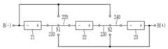
도 2를 참고하면, 밸런싱 회로는 복수의 스위치(210, 220, 230, 240)를 포함하며, 복수의 배터리 모듈(21, 22, 23)에 연결되어 있다.Referring to FIG. 2, the balancing circuit includes a plurality of switches (210, 220, 230, 240) and is connected to a plurality of battery modules (21, 22, 23).
복수의 배터리 모듈(21, 22, 23)에서, 배터리 모듈(21)의 음극 단자는 배터리 팩의 음극 출력 단자(B(-))에 연결되어 있으며, 배터리 모듈(23)의 양극 단자는 배터리 팩의 양극 출력 단자(B(+))에 연결되어 있다. 스위치(210, 220, 230, 240)는 BMS(도 1의 120)의 프로세서(도 1의 122)로부터의 제어 신호에 따라 배터리 모듈(21)의 양극 단자와 배터리 모듈(22)의 음극 단자 사이의 연결 및 배터리 모듈(22)의 양극 단자와 배터리 모듈(23)의 음극 단자 사이의 연결을 제어한다.In a plurality of battery modules (21, 22, 23), the negative terminal of the battery module (21) is connected to the negative output terminal (B(-)) of the battery pack, and the positive terminal of the battery module (23) is connected to the positive output terminal (B(+)) of the battery pack. Switches (210, 220, 230, 240) control the connection between the positive terminal of the battery module (21) and the negative terminal of the battery module (22) and the connection between the positive terminal of the battery module (22) and the negative terminal of the battery module (23) according to a control signal from a processor (122 of FIG. 1) of the BMS (120 of FIG. 1).
구체적으로, 전원 모드에서, 스위치(210, 220)는 배터리 모듈(21)의 양극 단자와 배터리 모듈(22)의 음극 단자를 연결하고, 스위치(230, 240)는 배터리 모듈(22)의 양극 단자와 배터리 모듈(23)의 음극 단자를 연결한다. 이에 따라, 복수의 배터리 모듈(21, 22, 23)은 직렬로 연결되어 원하는 전력을 공급할 수 있다. 밸런싱 모드에서, 스위치(210, 220)는 배터리 모듈(21)의 양극 단자를 배터리 팩의 양극 출력 단자(B(+))에 연결하고 배터리 모듈(22)의 음극 단자를 배터리 팩의 음극 출력 단자(B(-))에 연결하며, 스위치(230, 240)는 배터리 모듈(22)의 양극 단자를 배터리 팩의 양극 출력 단자(B(+))에 연결하고 배터리 모듈(23)의 음극 단자를 배터리 팩의 음극 출력 단자(B(-))에 연결한다. 이에 따라, 복수의 배터리 모듈(21, 22, 23)이 병렬로 연결되어, 배터리 모듈(21, 22, 23) 사이에서 전압 밸런싱이 수행될 수 있다. 즉, 배터리 모듈(21, 22, 23)의 전압이 균등화될 수 있다.Specifically, in the power mode, the switches (210, 220) connect the positive terminal of the battery module (21) to the negative terminal of the battery module (22), and the switches (230, 240) connect the positive terminal of the battery module (22) to the negative terminal of the battery module (23). Accordingly, a plurality of battery modules (21, 22, 23) can be connected in series to supply a desired power. In the balancing mode, the switches (210, 220) connect the positive terminal of the battery module (21) to the positive output terminal (B(+)) of the battery pack and connect the negative terminal of the battery module (22) to the negative output terminal (B(-)) of the battery pack, and the switches (230, 240) connect the positive terminal of the battery module (22) to the positive output terminal (B(+)) of the battery pack and connect the negative terminal of the battery module (23) to the negative output terminal (B(-)) of the battery pack. Accordingly, multiple battery modules (21, 22, 23) are connected in parallel, so that voltage balancing can be performed between the battery modules (21, 22, 23). That is, the voltages of the battery modules (21, 22, 23) can be equalized.
어떤 실시예에서, 밸런싱 회로(220)의 이러한 동작을 위해, 도 2에 도시한 바와 같이, 스위치(210)는 제1 단자가 배터리 모듈(21)의 양극 단자에 연결되고 제2 단자가 제1 노드(N1)와 배터리 팩의 양극 출력 단자(B(+)) 사이에서 스위칭할 수 있다. 스위치(220)는 제1 단자가 배터리 모듈(22)의 음극 단자에 연결되고 제2 단자가 제1 노드(N1)와 배터리 팩의 음극 출력 단자(B(-)) 사이에서 스위칭할 수 있다. 스위치(230)는 제1 단자가 배터리 모듈(22)의 양극 단자에 연결되고 제2 단자가 제2 노드(N2)와 배터리 팩의 양극 출력 단자(B(+)) 사이에서 스위칭할 수 있다. 스위치(240)는 제1 단자가 배터리 모듈(23)의 음극 단자에 연결되고 제2 단자가 제2 노드(N2)와 배터리 팩의 음극 출력 단자(B(-)) 사이에서 스위칭할 수 있다.In some embodiments, for such operation of the balancing circuit (220), as illustrated in FIG. 2, the switch (210) may have a first terminal connected to the positive terminal of the battery module (21) and a second terminal capable of switching between the first node (N1) and the positive output terminal (B(+)) of the battery pack. The switch (220) may have a first terminal connected to the negative terminal of the battery module (22) and a second terminal capable of switching between the first node (N1) and the negative output terminal (B(-)) of the battery pack. The switch (230) may have a first terminal connected to the positive terminal of the battery module (22) and a second terminal capable of switching between the second node (N2) and the positive output terminal (B(+)) of the battery pack. The switch (240) has a first terminal connected to the negative terminal of the battery module (23) and a second terminal that can switch between the second node (N2) and the negative output terminal (B(-)) of the battery pack.
다음, 도 2에 도시한 밸런싱 회로의 동작을 도 3 및 도 4를 참고로 하여 설명한다.Next, the operation of the balancing circuit shown in Fig. 2 will be explained with reference to Figs. 3 and 4.
도 3을 참고하면, 전원 모드에서, 프로세서로부터의 제어 신호에 응답하여 스위치(210)의 제2 단자와 스위치(220)의 제2 단자가 제1 노드(N1)에 연결되고, 스위치(230)의 제2 단자와 스위치(240)의 제2 단자가 제2 노드(N2)에 연결된다. 이에 따라, 복수의 배터리 모듈(21, 22, 23)은 직렬로 연결될 수 있다.Referring to FIG. 3, in the power mode, in response to a control signal from the processor, the second terminal of the switch (210) and the second terminal of the switch (220) are connected to the first node (N1), and the second terminal of the switch (230) and the second terminal of the switch (240) are connected to the second node (N2). Accordingly, a plurality of battery modules (21, 22, 23) can be connected in series.
도 4를 참고하면, 밸런싱 모드에서, 프로세서로부터의 제어 신호에 응답하여 스위치(210)의 제2 단자와 스위치(230)의 제2 단자가 배터리 팩의 양극 출력 단자(B(+))에 연결되고, 스위치(220)의 제2 단자와 스위치(240)의 제2 단자가 배터리 팩의 음극 출력 단자(B(-))에 연결된다. 이에 따라, 복수의 배터리 모듈(21, 22, 23)은 병렬로 연결될 수 있다.Referring to FIG. 4, in the balancing mode, in response to a control signal from the processor, the second terminal of the switch (210) and the second terminal of the switch (230) are connected to the positive output terminal (B(+)) of the battery pack, and the second terminal of the switch (220) and the second terminal of the switch (240) are connected to the negative output terminal (B(-)) of the battery pack. Accordingly, a plurality of battery modules (21, 22, 23) can be connected in parallel.
도 2 내지 도 4에서는 세 개의 배터리 모듈(21, 22, 23)을 예시하였지만, 두 개의 배터리 모듈(예를 들면, 21, 22)이 사용되는 경우, 스위치(230, 240)은 사용되지 않고, 배터리 모듈(22)의 양극 단자가 배터리 팩의 양극 출력 단자(B(+))에 연결되어 있다. 네 개 이상의 배터리 모듈이 사용되는 경우, 추가되는 배터리 모듈마다 두 개의 스위치(예를 들면, 210, 220) 쌍이 추가될 수 있다.In FIGS. 2 to 4, three battery modules (21, 22, 23) are exemplified, but when two battery modules (e.g., 21, 22) are used, the switches (230, 240) are not used, and the positive terminal of the battery module (22) is connected to the positive output terminal (B(+)) of the battery pack. When four or more battery modules are used, two pairs of switches (e.g., 210, 220) may be added for each additional battery module.
이와 같이, 본 발명의 한 실시예에 따르면, 전원 모드에서 복수의 배터리 모듈을 직렬로 연결하여서 원하는 전력을 공급할 수 있고, 밸런싱 모드에서 복수의 배터리 모듈을 병렬로 연결하여서 밸런싱을 수행할 수 있으므로, 배터리 모듈 사이에서 전압차가 발생하는 것을 방지할 수 있다.In this way, according to one embodiment of the present invention, a plurality of battery modules can be connected in series in the power mode to supply a desired power, and a plurality of battery modules can be connected in parallel in the balancing mode to perform balancing, thereby preventing a voltage difference from occurring between the battery modules.
한편, 복수의 배터리 모듈(21, 22, 23)의 전압 중에서 최대 전압과 최소 전압의 차이가 큰 경우에 밸런싱이 수행되면, 최대 전압을 출력하는 배터리 모듈과 최소 전압을 출력하는 배터리 모듈 사이에서 순간적으로 큰 전류, 즉 과전류가 흐를 수 있다. 아래에서는 과전류를 방지할 수 있는 실시예에 대해서 도 5 및 도 6을 참고로 하여 설명한다.Meanwhile, if balancing is performed when the difference between the maximum voltage and the minimum voltage among the voltages of the plurality of battery modules (21, 22, 23) is large, a large current, i.e., an overcurrent, may flow momentarily between the battery module outputting the maximum voltage and the battery module outputting the minimum voltage. Below, an embodiment capable of preventing an overcurrent will be described with reference to FIGS. 5 and 6.
도 5는 본 발명의 다른 실시예에 따른 배터리 관리 시스템의 밸런싱 동작을 나타내는 흐름도이며, 도 6은 본 발명의 또 다른 실시예에 따른 배터리 관리 시스템의 밸런싱 동작을 나타내는 흐름도이다.FIG. 5 is a flowchart showing a balancing operation of a battery management system according to another embodiment of the present invention, and FIG. 6 is a flowchart showing a balancing operation of a battery management system according to still another embodiment of the present invention.
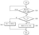
도 5를 참고하면, 프로세서(도 1의 122)는 배터리 장치가 밸런싱 동작이 가능한 상태인지를 판단한다(S510). 어떤 실시예에서, 프로세서(122)는 배터리 장치에서 외부 장치로 전력 공급이 필요하지 않은 경우, 밸런싱 동작이 가능한 상태로 판단할 수 있다.Referring to FIG. 5, the processor (122 of FIG. 1) determines whether the battery device is capable of a balancing operation (S510). In some embodiments, the processor (122) may determine that the battery device is capable of a balancing operation if power supply from an external device is not required.
밸런싱 동작이 가능한 상태인 경우, 프로세서(122)는 복수의 배터리 모듈(도 1의 111)의 전압 중에서 최대 전압(Vmax)과 최소 전압(Vmin)의 차이가 소정의 임계 전압(Vth)을 넘는지를 판단한다(S520). 최대 전압과 최소 전압의 차이가 임계 전압을 넘지 않는 경우, 프로세서(122)는 밸런싱 모드로 진입하여서 밸런싱 동작을 수행한다(S530).When the balancing operation is possible, the processor (122) determines whether the difference between the maximum voltage (Vmax) and the minimum voltage (Vmin) among the voltages of the plurality of battery modules (111 in FIG. 1) exceeds a predetermined threshold voltage (Vth) (S520). When the difference between the maximum voltage and the minimum voltage does not exceed the threshold voltage, the processor (122) enters the balancing mode and performs the balancing operation (S530).
최대 전압과 최소 전압의 차이가 임계 전압을 넘는 경우, 프로세서(122)는 밸런싱 모드로 진입하지 않는다(S540). 이와 같이, 최대 전압과 최소 전압의 차이가 임계 전압을 넘는 경우에 밸런싱 동작을 수행하지 않음으로써, 최대 전압을 출력하는 배터리 모듈에서 최소 전압을 출력하는 배터리 모듈로 흐를 수 있는 과전류를 방지할 수 있다.If the difference between the maximum voltage and the minimum voltage exceeds the threshold voltage, the processor (122) does not enter the balancing mode (S540). In this way, by not performing the balancing operation if the difference between the maximum voltage and the minimum voltage exceeds the threshold voltage, it is possible to prevent overcurrent that may flow from the battery module outputting the maximum voltage to the battery module outputting the minimum voltage.
도 6을 참고하면, 최대 전압과 최소 전압의 차이가 임계 전압을 넘는 경우, 프로세서(122)는 밸런싱 모드로 진입하지 않고 보호 동작을 수행할 수 있다(S541).Referring to FIG. 6, if the difference between the maximum voltage and the minimum voltage exceeds the threshold voltage, the processor (122) can perform a protection operation without entering the balancing mode (S541).
어떤 실시예에서, 최대 전압과 최소 전압의 차이가 임계 전압을 넘는 경우, 프로세서(122)는 진단이 필요하다는 알림을 출력할 수 있다(S541).In some embodiments, if the difference between the maximum voltage and the minimum voltage exceeds a threshold voltage, the processor (122) may output a notification that diagnosis is required (S541).
어떤 실시예에서, 최대 전압과 최소 전압의 차이가 임계 전압을 넘는 경우, 프로세서(122)는 최대 전압을 출력하는 배터리 모듈의 각 배터리 셀에서 셀 밸런싱을 수행할 수 있다(S541). 예를 들면, 프로세서(122)는 각 배터리 셀에 연결된 셀 밸런싱 회로의 저항을 통해 배터리 셀의 전압을 방전시킬 수 있다.In some embodiments, when the difference between the maximum voltage and the minimum voltage exceeds the threshold voltage, the processor (122) may perform cell balancing on each battery cell of the battery module that outputs the maximum voltage (S541). For example, the processor (122) may discharge the voltage of the battery cell through the resistance of the cell balancing circuit connected to each battery cell.
이상에서 본 발명의 실시예에 대하여 상세하게 설명하였지만 본 발명의 권리범위는 이에 한정되는 것은 아니고 다음의 청구범위에서 정의하고 있는 본 발명의 기본 개념을 이용한 당업자의 여러 변형 및 개량 형태 또한 본 발명의 권리범위에 속하는 것이다.Although the embodiments of the present invention have been described in detail above, the scope of the present invention is not limited thereto, and various modifications and improvements made by those skilled in the art using the basic concept of the present invention defined in the following claims also fall within the scope of the present invention.
Claims (11)
Translated fromKorean프로세서, 그리고
상기 배터리 관리 시스템이 사용되는 이동 수단의 주행 모드에서 상기 프로세서의 제어에 따라 상기 복수의 배터리 모듈을 직렬로 연결하여 상기 배터리 팩에서 상기 이동 수단에 전력을 공급하고, 상기 이동 수단의 주차 모드에서 상기 프로세서의 제어에 따라 상기 복수의 배터리 모듈을 병렬로 연결하여 상기 복수의 배터리 모듈에서 밸런싱을 수행하는 밸런싱 회로
를 포함하는 배터리 관리 시스템.A battery management system comprising a plurality of battery cells connected to a battery pack comprising a plurality of battery modules, each battery module being connected in series,
processor, and
A balancing circuit that connects the plurality of battery modules in series under the control of the processor in a driving mode of a vehicle in which the battery management system is used to supply power to the vehicle from the battery pack, and connects the plurality of battery modules in parallel under the control of the processor in a parking mode of the vehicle to perform balancing on the plurality of battery modules.
A battery management system comprising:
상기 복수의 배터리 모듈은 제1 배터리 모듈과 제2 배터리 모듈을 포함하며,
상기 밸런싱 회로는,
상기 주행 모드에서 상기 제1 배터리 모듈의 양극 단자와 제1 노드를 연결하며, 상기 주차 모드에서 상기 제1 배터리 모듈의 양극 단자와 상기 배터리 팩의 양극 출력 단자를 연결하는 제1 스위치, 그리고
상기 주행 모드에서 상기 제2 배터리 모듈의 음극 단자와 상기 제1 노드를 연결하며, 상기 주차 모드에서 상기 제2 배터리 모듈의 음극 단자와 상기 배터리 팩의 음극 출력 단자를 연결하는 제2 스위치
를 포함하는 배터리 관리 시스템.In paragraph 1,
The above plurality of battery modules include a first battery module and a second battery module,
The above balancing circuit,
A first switch that connects the positive terminal of the first battery module and the first node in the driving mode, and connects the positive terminal of the first battery module and the positive output terminal of the battery pack in the parking mode, and
A second switch that connects the negative terminal of the second battery module and the first node in the driving mode, and connects the negative terminal of the second battery module and the negative output terminal of the battery pack in the parking mode.
A battery management system comprising:
상기 복수의 배터리 모듈은 제3 배터리 모듈을 더 포함하며,
상기 밸런싱 회로는,
상기 주행 모드에서 상기 제2 배터리 모듈의 양극 단자와 제2 노드를 연결하며, 상기 주차 모드에서 상기 제2 배터리 모듈의 양극 단자와 상기 배터리 팩의 양극 출력 단자를 연결하는 제3 스위치, 그리고
상기 주행 모드에서 상기 제3 배터리 모듈의 음극 단자와 상기 제2 노드를 연결하며, 상기 주차 모드에서 상기 제3 배터리 모듈의 음극 단자와 상기 배터리 팩의 음극 출력 단자를 연결하는 제4 스위치
를 더 포함하는 배터리 관리 시스템.In paragraph 3,
The above plurality of battery modules further include a third battery module,
The above balancing circuit,
A third switch that connects the positive terminal of the second battery module and the second node in the driving mode, and connects the positive terminal of the second battery module and the positive output terminal of the battery pack in the parking mode, and
A fourth switch that connects the negative terminal of the third battery module and the second node in the driving mode, and connects the negative terminal of the third battery module and the negative output terminal of the battery pack in the parking mode.
A battery management system further comprising:
상기 프로세서는, 상기 복수의 배터리 모듈의 전압 중에서 최대 전압과 최소 전압이 차이가 임계 전압을 넘지 않는 경우, 상기 주차 모드로 진입하는 배터리 관리 시스템.In paragraph 1,
The above processor is a battery management system that enters the parking mode when the difference between the maximum voltage and the minimum voltage among the voltages of the plurality of battery modules does not exceed a threshold voltage.
상기 프로세서는, 상기 복수의 배터리 모듈의 전압 중에서 최대 전압과 최소 전압이 차이가 임계 전압을 넘는 경우, 진단이 필요하다는 알림을 출력하는 배터리 관리 시스템.In Article 5,
The above processor is a battery management system that outputs a notification that diagnosis is necessary when the difference between the maximum voltage and the minimum voltage among the voltages of the plurality of battery modules exceeds a threshold voltage.
상기 프로세서는, 상기 복수의 배터리 모듈의 전압 중에서 최대 전압과 최소 전압이 차이가 임계 전압을 넘는 경우, 상기 최대 전압을 가지는 배터리 모듈에서 셀 밸런싱을 수행하는 배터리 관리 시스템.In Article 5,
The above processor is a battery management system that performs cell balancing in the battery module having the maximum voltage when the difference between the maximum voltage and the minimum voltage among the voltages of the plurality of battery modules exceeds a threshold voltage.
상기 배터리 관리 시스템이 사용되는 이동 수단의 주행 모드에서 상기 복수의 배터리 모듈을 직렬로 연결하여 상기 배터리 팩에서 상기 이동 수단에 전력을 공급하는 단계, 그리고
상기 이동 수단의 주차 모드에서 상기 복수의 배터리 모듈을 병렬로 연결하여 상기 복수의 배터리 모듈에서 밸런싱을 수행하는 단계
를 포함하는 밸런싱 방법.A method of balancing a battery management system comprising a plurality of battery cells connected to a battery pack comprising a plurality of battery modules, each battery module being connected in series, comprising:
A step of connecting the plurality of battery modules in series in a driving mode of a vehicle in which the battery management system is used to supply power to the vehicle from the battery pack, and
A step of performing balancing on the plurality of battery modules by connecting the plurality of battery modules in parallel in the parking mode of the above-mentioned means of transportation.
A balancing method comprising:
상기 복수의 배터리 모듈의 전압 중에서 최대 전압과 최소 전압이 차이가 임계 전압을 넘지 않는 경우, 상기 주차 모드로 진입하는 단계를 더 포함하는 밸런싱 방법.In Article 8,
A balancing method further comprising a step of entering the parking mode when the difference between the maximum voltage and the minimum voltage among the voltages of the plurality of battery modules does not exceed a threshold voltage.
상기 복수의 배터리 모듈의 전압 중에서 최대 전압과 최소 전압이 차이가 임계 전압을 넘는 경우, 진단이 필요하다는 알림을 출력하는 단계를 더 포함하는 밸런싱 방법.In Article 9,
A balancing method further comprising the step of outputting a notification that diagnosis is necessary when the difference between the maximum voltage and the minimum voltage among the voltages of the plurality of battery modules exceeds a threshold voltage.
상기 복수의 배터리 모듈의 전압 중에서 최대 전압과 최소 전압이 차이가 임계 전압을 넘는 경우, 상기 최대 전압을 가지는 배터리 모듈에서 셀 밸런싱을 수행하는 단계를 더 포함하는 밸런싱 방법.In Article 9,
A balancing method further comprising the step of performing cell balancing in the battery module having the maximum voltage when the difference between the maximum voltage and the minimum voltage among the voltages of the plurality of battery modules exceeds a threshold voltage.
Priority Applications (1)
| Application Number | Priority Date | Filing Date | Title |
|---|---|---|---|
| KR1020190131706AKR102796089B1 (en) | 2019-10-22 | 2019-10-22 | Battery management system and balancing method |
Applications Claiming Priority (1)
| Application Number | Priority Date | Filing Date | Title |
|---|---|---|---|
| KR1020190131706AKR102796089B1 (en) | 2019-10-22 | 2019-10-22 | Battery management system and balancing method |
Publications (2)
| Publication Number | Publication Date |
|---|---|
| KR20210047750A KR20210047750A (en) | 2021-04-30 |
| KR102796089B1true KR102796089B1 (en) | 2025-04-14 |
Family
ID=75740693
Family Applications (1)
| Application Number | Title | Priority Date | Filing Date |
|---|---|---|---|
| KR1020190131706AActiveKR102796089B1 (en) | 2019-10-22 | 2019-10-22 | Battery management system and balancing method |
Country Status (1)
| Country | Link |
|---|---|
| KR (1) | KR102796089B1 (en) |
Families Citing this family (1)
| Publication number | Priority date | Publication date | Assignee | Title |
|---|---|---|---|---|
| KR102412601B1 (en) | 2021-09-14 | 2022-06-24 | 나노인텍 주식회사 | Universal battery pack and system using universal battery pack |
Citations (1)
| Publication number | Priority date | Publication date | Assignee | Title |
|---|---|---|---|---|
| KR101988027B1 (en)* | 2018-09-21 | 2019-06-11 | 주식회사 다음코리아 | Blancing Apparatus for Battery and Method thereof |
Family Cites Families (1)
| Publication number | Priority date | Publication date | Assignee | Title |
|---|---|---|---|---|
| KR20190027450A (en)* | 2017-09-07 | 2019-03-15 | 르노삼성자동차 주식회사 | The structure for traction battery by switching series and parallel in two modes |
- 2019
- 2019-10-22KRKR1020190131706Apatent/KR102796089B1/enactiveActive
Patent Citations (1)
| Publication number | Priority date | Publication date | Assignee | Title |
|---|---|---|---|---|
| KR101988027B1 (en)* | 2018-09-21 | 2019-06-11 | 주식회사 다음코리아 | Blancing Apparatus for Battery and Method thereof |
Also Published As
| Publication number | Publication date |
|---|---|
| KR20210047750A (en) | 2021-04-30 |
Similar Documents
| Publication | Publication Date | Title |
|---|---|---|
| US6781343B1 (en) | Hybrid power supply device | |
| KR101367875B1 (en) | Apparatus for controlling connection of battery pack | |
| US8054044B2 (en) | Apparatus and method for balancing of battery cell'S charge capacity | |
| JP6392997B2 (en) | Control device, power storage device, and power storage system | |
| US7928691B2 (en) | Method and system for cell equalization with isolated charging sources | |
| KR101677679B1 (en) | Power management circuit for rechargeable battery stack | |
| US20090267565A1 (en) | Method and system for cell equalization with charging sources and shunt regulators | |
| WO2012053292A1 (en) | Battery pack, method for charging/discharging same, and power consumption device | |
| US9434272B2 (en) | Battery management system | |
| KR100666817B1 (en) | Battery balancing device and method | |
| KR20150089627A (en) | Battery cell voltage balancing apparatus and method | |
| KR20150013302A (en) | Charge balancing in a battery | |
| US12003125B2 (en) | Tool circuitry for series-type connected battery packs | |
| JP5664310B2 (en) | DC power supply | |
| KR20160132633A (en) | Battery system and control method for connection of the same | |
| KR20220025414A (en) | BATTERY APPARATUS and method for selecting battery pack | |
| KR101988027B1 (en) | Blancing Apparatus for Battery and Method thereof | |
| KR20180035080A (en) | Battery cell balancing circuit | |
| JP6932607B2 (en) | DC power supply system | |
| KR102796089B1 (en) | Battery management system and balancing method | |
| JP2020018085A (en) | Electrical power system and management device | |
| CN110816311B (en) | Method for operating a battery system and electric vehicle | |
| KR20220100332A (en) | Battery apparatus and method of supplying voltage | |
| US20250007012A1 (en) | Battery device and balancing method | |
| US20230133126A1 (en) | Battery system and method for controlling a battery system |
Legal Events
| Date | Code | Title | Description |
|---|---|---|---|
| PA0109 | Patent application | Patent event code:PA01091R01D Comment text:Patent Application Patent event date:20191022 | |
| PG1501 | Laying open of application | ||
| N231 | Notification of change of applicant | ||
| PN2301 | Change of applicant | Patent event date:20210510 Comment text:Notification of Change of Applicant Patent event code:PN23011R01D | |
| A201 | Request for examination | ||
| PA0201 | Request for examination | Patent event code:PA02012R01D Patent event date:20220825 Comment text:Request for Examination of Application Patent event code:PA02011R01I Patent event date:20191022 Comment text:Patent Application | |
| E902 | Notification of reason for refusal | ||
| PE0902 | Notice of grounds for rejection | Comment text:Notification of reason for refusal Patent event date:20240808 Patent event code:PE09021S01D | |
| E701 | Decision to grant or registration of patent right | ||
| PE0701 | Decision of registration | Patent event code:PE07011S01D Comment text:Decision to Grant Registration Patent event date:20250401 | |
| GRNT | Written decision to grant | ||
| PR0701 | Registration of establishment | Comment text:Registration of Establishment Patent event date:20250410 Patent event code:PR07011E01D | |
| PR1002 | Payment of registration fee | Payment date:20250410 End annual number:3 Start annual number:1 | |
| PG1601 | Publication of registration |