KR102793671B1 - Electrochemical cells having semi-solid electrodes and methods of manufacturing the same - Google Patents
Electrochemical cells having semi-solid electrodes and methods of manufacturing the sameDownload PDFInfo
- Publication number
- KR102793671B1 KR102793671B1KR1020237041858AKR20237041858AKR102793671B1KR 102793671 B1KR102793671 B1KR 102793671B1KR 1020237041858 AKR1020237041858 AKR 1020237041858AKR 20237041858 AKR20237041858 AKR 20237041858AKR 102793671 B1KR102793671 B1KR 102793671B1
- Authority
- KR
- South Korea
- Prior art keywords
- current collector
- electrochemical cell
- semi
- solid
- tab
- Prior art date
- Legal status (The legal status is an assumption and is not a legal conclusion. Google has not performed a legal analysis and makes no representation as to the accuracy of the status listed.)
- Active
Links
Images


Classifications
- H—ELECTRICITY
- H01—ELECTRIC ELEMENTS
- H01M—PROCESSES OR MEANS, e.g. BATTERIES, FOR THE DIRECT CONVERSION OF CHEMICAL ENERGY INTO ELECTRICAL ENERGY
- H01M4/00—Electrodes
- H01M4/02—Electrodes composed of, or comprising, active material
- H—ELECTRICITY
- H01—ELECTRIC ELEMENTS
- H01M—PROCESSES OR MEANS, e.g. BATTERIES, FOR THE DIRECT CONVERSION OF CHEMICAL ENERGY INTO ELECTRICAL ENERGY
- H01M10/00—Secondary cells; Manufacture thereof
- H01M10/04—Construction or manufacture in general
- H01M10/0413—Large-sized flat cells or batteries for motive or stationary systems with plate-like electrodes
- H—ELECTRICITY
- H01—ELECTRIC ELEMENTS
- H01M—PROCESSES OR MEANS, e.g. BATTERIES, FOR THE DIRECT CONVERSION OF CHEMICAL ENERGY INTO ELECTRICAL ENERGY
- H01M10/00—Secondary cells; Manufacture thereof
- H01M10/04—Construction or manufacture in general
- H01M10/0436—Small-sized flat cells or batteries for portable equipment
- H—ELECTRICITY
- H01—ELECTRIC ELEMENTS
- H01M—PROCESSES OR MEANS, e.g. BATTERIES, FOR THE DIRECT CONVERSION OF CHEMICAL ENERGY INTO ELECTRICAL ENERGY
- H01M10/00—Secondary cells; Manufacture thereof
- H01M10/04—Construction or manufacture in general
- H01M10/049—Processes for forming or storing electrodes in the battery container
- H—ELECTRICITY
- H01—ELECTRIC ELEMENTS
- H01M—PROCESSES OR MEANS, e.g. BATTERIES, FOR THE DIRECT CONVERSION OF CHEMICAL ENERGY INTO ELECTRICAL ENERGY
- H01M10/00—Secondary cells; Manufacture thereof
- H01M10/05—Accumulators with non-aqueous electrolyte
- H01M10/052—Li-accumulators
- H—ELECTRICITY
- H01—ELECTRIC ELEMENTS
- H01M—PROCESSES OR MEANS, e.g. BATTERIES, FOR THE DIRECT CONVERSION OF CHEMICAL ENERGY INTO ELECTRICAL ENERGY
- H01M10/00—Secondary cells; Manufacture thereof
- H01M10/05—Accumulators with non-aqueous electrolyte
- H01M10/052—Li-accumulators
- H01M10/0525—Rocking-chair batteries, i.e. batteries with lithium insertion or intercalation in both electrodes; Lithium-ion batteries
- H—ELECTRICITY
- H01—ELECTRIC ELEMENTS
- H01M—PROCESSES OR MEANS, e.g. BATTERIES, FOR THE DIRECT CONVERSION OF CHEMICAL ENERGY INTO ELECTRICAL ENERGY
- H01M10/00—Secondary cells; Manufacture thereof
- H01M10/05—Accumulators with non-aqueous electrolyte
- H01M10/058—Construction or manufacture
- H01M10/0585—Construction or manufacture of accumulators having only flat construction elements, i.e. flat positive electrodes, flat negative electrodes and flat separators
- H—ELECTRICITY
- H01—ELECTRIC ELEMENTS
- H01M—PROCESSES OR MEANS, e.g. BATTERIES, FOR THE DIRECT CONVERSION OF CHEMICAL ENERGY INTO ELECTRICAL ENERGY
- H01M4/00—Electrodes
- H01M4/02—Electrodes composed of, or comprising, active material
- H01M4/04—Processes of manufacture in general
- H01M4/0402—Methods of deposition of the material
- H01M4/0404—Methods of deposition of the material by coating on electrode collectors
- H—ELECTRICITY
- H01—ELECTRIC ELEMENTS
- H01M—PROCESSES OR MEANS, e.g. BATTERIES, FOR THE DIRECT CONVERSION OF CHEMICAL ENERGY INTO ELECTRICAL ENERGY
- H01M4/00—Electrodes
- H01M4/02—Electrodes composed of, or comprising, active material
- H01M4/04—Processes of manufacture in general
- H01M4/0402—Methods of deposition of the material
- H01M4/0407—Methods of deposition of the material by coating on an electrolyte layer
- H—ELECTRICITY
- H01—ELECTRIC ELEMENTS
- H01M—PROCESSES OR MEANS, e.g. BATTERIES, FOR THE DIRECT CONVERSION OF CHEMICAL ENERGY INTO ELECTRICAL ENERGY
- H01M4/00—Electrodes
- H01M4/02—Electrodes composed of, or comprising, active material
- H01M4/04—Processes of manufacture in general
- H01M4/0402—Methods of deposition of the material
- H01M4/0409—Methods of deposition of the material by a doctor blade method, slip-casting or roller coating
- H—ELECTRICITY
- H01—ELECTRIC ELEMENTS
- H01M—PROCESSES OR MEANS, e.g. BATTERIES, FOR THE DIRECT CONVERSION OF CHEMICAL ENERGY INTO ELECTRICAL ENERGY
- H01M4/00—Electrodes
- H01M4/02—Electrodes composed of, or comprising, active material
- H01M4/04—Processes of manufacture in general
- H01M4/0473—Filling tube-or pockets type electrodes; Applying active mass in cup-shaped terminals
- H—ELECTRICITY
- H01—ELECTRIC ELEMENTS
- H01M—PROCESSES OR MEANS, e.g. BATTERIES, FOR THE DIRECT CONVERSION OF CHEMICAL ENERGY INTO ELECTRICAL ENERGY
- H01M4/00—Electrodes
- H01M4/02—Electrodes composed of, or comprising, active material
- H01M4/13—Electrodes for accumulators with non-aqueous electrolyte, e.g. for lithium-accumulators; Processes of manufacture thereof
- H—ELECTRICITY
- H01—ELECTRIC ELEMENTS
- H01M—PROCESSES OR MEANS, e.g. BATTERIES, FOR THE DIRECT CONVERSION OF CHEMICAL ENERGY INTO ELECTRICAL ENERGY
- H01M4/00—Electrodes
- H01M4/02—Electrodes composed of, or comprising, active material
- H01M4/36—Selection of substances as active materials, active masses, active liquids
- H—ELECTRICITY
- H01—ELECTRIC ELEMENTS
- H01M—PROCESSES OR MEANS, e.g. BATTERIES, FOR THE DIRECT CONVERSION OF CHEMICAL ENERGY INTO ELECTRICAL ENERGY
- H01M4/00—Electrodes
- H01M4/02—Electrodes composed of, or comprising, active material
- H01M4/64—Carriers or collectors
- H01M4/66—Selection of materials
- H01M4/661—Metal or alloys, e.g. alloy coatings
- H—ELECTRICITY
- H01—ELECTRIC ELEMENTS
- H01M—PROCESSES OR MEANS, e.g. BATTERIES, FOR THE DIRECT CONVERSION OF CHEMICAL ENERGY INTO ELECTRICAL ENERGY
- H01M4/00—Electrodes
- H01M4/02—Electrodes composed of, or comprising, active material
- H01M4/64—Carriers or collectors
- H01M4/70—Carriers or collectors characterised by shape or form
- H—ELECTRICITY
- H01—ELECTRIC ELEMENTS
- H01M—PROCESSES OR MEANS, e.g. BATTERIES, FOR THE DIRECT CONVERSION OF CHEMICAL ENERGY INTO ELECTRICAL ENERGY
- H01M50/00—Constructional details or processes of manufacture of the non-active parts of electrochemical cells other than fuel cells, e.g. hybrid cells
- H01M50/10—Primary casings; Jackets or wrappings
- H01M50/102—Primary casings; Jackets or wrappings characterised by their shape or physical structure
- H01M50/105—Pouches or flexible bags
- H—ELECTRICITY
- H01—ELECTRIC ELEMENTS
- H01M—PROCESSES OR MEANS, e.g. BATTERIES, FOR THE DIRECT CONVERSION OF CHEMICAL ENERGY INTO ELECTRICAL ENERGY
- H01M50/00—Constructional details or processes of manufacture of the non-active parts of electrochemical cells other than fuel cells, e.g. hybrid cells
- H01M50/40—Separators; Membranes; Diaphragms; Spacing elements inside cells
- H01M50/46—Separators, membranes or diaphragms characterised by their combination with electrodes
- H—ELECTRICITY
- H01—ELECTRIC ELEMENTS
- H01M—PROCESSES OR MEANS, e.g. BATTERIES, FOR THE DIRECT CONVERSION OF CHEMICAL ENERGY INTO ELECTRICAL ENERGY
- H01M50/00—Constructional details or processes of manufacture of the non-active parts of electrochemical cells other than fuel cells, e.g. hybrid cells
- H01M50/50—Current conducting connections for cells or batteries
- H01M50/543—Terminals
- H01M50/552—Terminals characterised by their shape
- H01M50/553—Terminals adapted for prismatic, pouch or rectangular cells
- H01M50/557—Plate-shaped terminals
- H—ELECTRICITY
- H01—ELECTRIC ELEMENTS
- H01M—PROCESSES OR MEANS, e.g. BATTERIES, FOR THE DIRECT CONVERSION OF CHEMICAL ENERGY INTO ELECTRICAL ENERGY
- H01M4/00—Electrodes
- H01M4/02—Electrodes composed of, or comprising, active material
- H01M2004/021—Physical characteristics, e.g. porosity, surface area
- H—ELECTRICITY
- H01—ELECTRIC ELEMENTS
- H01M—PROCESSES OR MEANS, e.g. BATTERIES, FOR THE DIRECT CONVERSION OF CHEMICAL ENERGY INTO ELECTRICAL ENERGY
- H01M4/00—Electrodes
- H01M4/02—Electrodes composed of, or comprising, active material
- H01M2004/023—Gel electrode
- H—ELECTRICITY
- H01—ELECTRIC ELEMENTS
- H01M—PROCESSES OR MEANS, e.g. BATTERIES, FOR THE DIRECT CONVERSION OF CHEMICAL ENERGY INTO ELECTRICAL ENERGY
- H01M4/00—Electrodes
- H01M4/02—Electrodes composed of, or comprising, active material
- H01M2004/026—Electrodes composed of, or comprising, active material characterised by the polarity
- H01M2004/029—Bipolar electrodes
- H—ELECTRICITY
- H01—ELECTRIC ELEMENTS
- H01M—PROCESSES OR MEANS, e.g. BATTERIES, FOR THE DIRECT CONVERSION OF CHEMICAL ENERGY INTO ELECTRICAL ENERGY
- H01M2220/00—Batteries for particular applications
- H01M2220/30—Batteries in portable systems, e.g. mobile phone, laptop
- H—ELECTRICITY
- H01—ELECTRIC ELEMENTS
- H01M—PROCESSES OR MEANS, e.g. BATTERIES, FOR THE DIRECT CONVERSION OF CHEMICAL ENERGY INTO ELECTRICAL ENERGY
- H01M4/00—Electrodes
- H01M4/02—Electrodes composed of, or comprising, active material
- H01M4/13—Electrodes for accumulators with non-aqueous electrolyte, e.g. for lithium-accumulators; Processes of manufacture thereof
- H01M4/139—Processes of manufacture
- H—ELECTRICITY
- H01—ELECTRIC ELEMENTS
- H01M—PROCESSES OR MEANS, e.g. BATTERIES, FOR THE DIRECT CONVERSION OF CHEMICAL ENERGY INTO ELECTRICAL ENERGY
- H01M50/00—Constructional details or processes of manufacture of the non-active parts of electrochemical cells other than fuel cells, e.g. hybrid cells
- H01M50/10—Primary casings; Jackets or wrappings
- H01M50/183—Sealing members
- Y—GENERAL TAGGING OF NEW TECHNOLOGICAL DEVELOPMENTS; GENERAL TAGGING OF CROSS-SECTIONAL TECHNOLOGIES SPANNING OVER SEVERAL SECTIONS OF THE IPC; TECHNICAL SUBJECTS COVERED BY FORMER USPC CROSS-REFERENCE ART COLLECTIONS [XRACs] AND DIGESTS
- Y02—TECHNOLOGIES OR APPLICATIONS FOR MITIGATION OR ADAPTATION AGAINST CLIMATE CHANGE
- Y02E—REDUCTION OF GREENHOUSE GAS [GHG] EMISSIONS, RELATED TO ENERGY GENERATION, TRANSMISSION OR DISTRIBUTION
- Y02E60/00—Enabling technologies; Technologies with a potential or indirect contribution to GHG emissions mitigation
- Y02E60/10—Energy storage using batteries
- Y—GENERAL TAGGING OF NEW TECHNOLOGICAL DEVELOPMENTS; GENERAL TAGGING OF CROSS-SECTIONAL TECHNOLOGIES SPANNING OVER SEVERAL SECTIONS OF THE IPC; TECHNICAL SUBJECTS COVERED BY FORMER USPC CROSS-REFERENCE ART COLLECTIONS [XRACs] AND DIGESTS
- Y02—TECHNOLOGIES OR APPLICATIONS FOR MITIGATION OR ADAPTATION AGAINST CLIMATE CHANGE
- Y02P—CLIMATE CHANGE MITIGATION TECHNOLOGIES IN THE PRODUCTION OR PROCESSING OF GOODS
- Y02P70/00—Climate change mitigation technologies in the production process for final industrial or consumer products
- Y02P70/50—Manufacturing or production processes characterised by the final manufactured product
Landscapes
- Chemical & Material Sciences (AREA)
- Chemical Kinetics & Catalysis (AREA)
- Electrochemistry (AREA)
- General Chemical & Material Sciences (AREA)
- Engineering & Computer Science (AREA)
- Manufacturing & Machinery (AREA)
- Materials Engineering (AREA)
- Secondary Cells (AREA)
- Battery Electrode And Active Subsutance (AREA)
- Cell Electrode Carriers And Collectors (AREA)
- Sealing Battery Cases Or Jackets (AREA)
- Electric Double-Layer Capacitors Or The Like (AREA)
Abstract
Translated fromKorean
Description
Translated fromKorean<관련 출원과의 교차-참조><Cross-reference with related applications>
본 출원은 2014년 11월 5일에 출원된 발명의 명칭 "Electrochemical Cells Having Semi-Solid Electrodes and Methods of Manufacturing the Same"의 U.S. 가출원 제62/075,373호의 우선권 및 이익을 주장하며, 상기 가출원의 개시 내용은 그 전문이 본원에 참조로 포함된다.This application claims priority to and the benefit of U.S. Provisional Application No. 62/075,373, filed November 5, 2014, entitled "Electrochemical Cells Having Semi-Solid Electrodes and Methods of Manufacturing the Same," the disclosure of which is incorporated herein by reference in its entirety.
본원에 기술된 실시양태는 일반적으로 집전체의 한쪽 면 상에만 코팅된 반고체 전극을 갖는 전기화학 전지, 이러한 전기화학 전지의 적층체, 및 이러한 전기화학 전지 적층체의 형성 방법에 관한 것이다.Embodiments described herein generally relate to electrochemical cells having a semi-solid electrode coated on only one side of a current collector, laminates of such electrochemical cells, and methods for forming such electrochemical cell laminates.
배터리는 전형적으로 고체 전극, 분리기, 전해질, 및 부수적 성분, 예컨대, 예를 들어, 포장, 열 관리, 전지 밸런싱, 전류 캐리어의 단자 내로의 통합, 및/또는 다른 이러한 성분으로 구성된다. 전극은 전형적으로 활성 물질, 전도성 물질, 결합제 및 다른 첨가제를 포함한다.A battery typically consists of solid electrodes, a separator, an electrolyte, and auxiliary components, such as, for example, packaging, thermal management, cell balancing, integration of current carriers into the terminals, and/or other such components. The electrodes typically include active materials, conductive materials, binders, and other additives.
일부 공지된 배터리 제조 방법은, 금속성 기판 (예를 들어, 집전체)을 용매 중에 용해 또는 분산된 활성 물질, 전도성 첨가제 및 결합제로 구성된 슬러리로 코팅하고, 용매를 증발시키고, 건조된 고체 매트릭스를 특정된 두께로 캘린더링하는 것을 포함한다. 이어서, 전극을 절단하고, 다른 성분과 함께 포장하고, 전해질을 함침시키고, 이어서 전체 포장체를 밀봉한다.Some known battery manufacturing methods involve coating a metallic substrate (e.g., a current collector) with a slurry comprising active materials, conductive additives, and binders dissolved or dispersed in a solvent, evaporating the solvent, and calendering the dried solid matrix to a specified thickness. The electrodes are then cut, packaged together with other components, impregnated with an electrolyte, and the entire package is then sealed.
이러한 공지된 방법은 일반적으로 전극의 캐스팅과 같은 복잡하고 비용이 많이 드는 제조 단계를 포함하며, 제한된 두께, 예를 들어 100 ㎛ 미만 (최종 단일 면 코팅 두께)의 전극에만 적합하다. 이들 제한된 두께의 전극의 공지된 제조 방법은 더 낮은 용량, 더 낮은 에너지 밀도 및 높은 불활성 성분 대 활성 물질 비를 갖는 배터리를 초래한다. 게다가, 공지된 전극 배합물에 사용되는 결합제는 전극의 비틀림도(tortuosity)를 증가시키고 이온 전도도를 감소시킬 수 있다.These known methods generally involve complex and costly manufacturing steps, such as casting of the electrodes, and are only suitable for electrodes of limited thickness, for example less than 100 μm (final single-sided coating thickness). These known methods for manufacturing electrodes of limited thickness result in batteries having lower capacity, lower energy density and high inert component to active material ratio. Furthermore, binders used in known electrode formulations can increase the tortuosity of the electrodes and reduce the ionic conductivity.
활성 물질 대 불활성 물질의 비를 증가시키기 위해, 일반적으로 전극 활성 물질 (즉, 애노드 배합물 슬러리 및 캐소드 배합물 슬러리)을 집전체의 양쪽 면 상에 코팅함으로써 통상의 전기화학 전지를 형성한다. 분리기를 전극들 사이, 즉 애노드와 캐소드 사이에 배치하여, 통상의 전기화학 전지를 형성한다. 복수의 이러한 전기화학 전지들을, 일반적으로 그들 사이에 배치된 이격자와 함께, 서로의 위에 적층하여, 전기화학 전지 적층체를 형성할 수 있다. 이로 인해 활성 물질 대 불활성 물질 비에 긍정적인 영향이 미쳐지지만, 제조 공정이 복잡해진다. 게다가, 전기화학 배터리를 조립하는 데 요구되는 시간이 상당할 수 있다. 이로 인해, 온도 변동 또는 습기에의 전극 물질의 노출이 증가하여, 전극 물질이 열화됨으로써, 전극의 전자 특성이 열화될 수 있다.To increase the ratio of active material to inert material, a conventional electrochemical cell is typically formed by coating electrode active materials (i.e., an anode compound slurry and a cathode compound slurry) on both sides of a current collector. A separator is disposed between the electrodes, i.e., between the anode and the cathode, to form a conventional electrochemical cell. A plurality of such electrochemical cells can be stacked on top of each other, typically with a spacer disposed between them, to form an electrochemical cell stack. This has a positive effect on the active material to inert material ratio, but complicates the manufacturing process. In addition, the time required to assemble the electrochemical battery can be significant. This can increase the exposure of the electrode materials to temperature fluctuations or moisture, which can deteriorate the electronic properties of the electrodes by degrading the electrode materials.
따라서, 더 긴 사이클 수명, 증가된 에너지 밀도, 충전 용량 및 전체 성능을 갖는 신규한 전기화학 배터리 및 전극을 개발하는 것이 에너지 저장 시스템 개발의 지속적인 목표이다.Therefore, developing novel electrochemical batteries and electrodes with longer cycle life, increased energy density, charge capacity, and overall performance is an ongoing goal in energy storage system development.
<요약><Summary>
본원에 기술된 실시양태는 일반적으로 집전체의 한쪽 면 상에만 코팅된 반고체 전극을 갖는 전기화학 전지에 관한 것이다. 일부 실시양태에서, 전기화학 전지는 포지티브 집전체의 한쪽 면 상에만 코팅된 반고체 포지티브 전극 및 네거티브 집전체의 한쪽 면 상에만 코팅된 반고체 네거티브 전극을 포함한다. 분리기는 반고체 포지티브 전극과 반고체 네거티브 전극 사이에 배치된다. 반고체 포지티브 전극 및 반고체 네거티브 전극 중 적어도 하나는 적어도 약 250 ㎛의 두께를 가질 수 있다.Embodiments described herein generally relate to an electrochemical cell having a semi-solid electrode coated on only one side of a current collector. In some embodiments, the electrochemical cell comprises a semi-solid positive electrode coated on only one side of a positive current collector and a semi-solid negative electrode coated on only one side of a negative current collector. A separator is disposed between the semi-solid positive electrode and the semi-solid negative electrode. At least one of the semi-solid positive electrode and the semi-solid negative electrode can have a thickness of at least about 250 μm.
도 1은 한 실시양태에 따른 전기화학 전지의 개략적 도해이다.
도 2는 한 실시양태에 따른 파우치 내의 전기화학 전지의 투시도이다.
도 3은 파우치가 제거된 상태의, 도 2의 전기화학 전지를 도시한다.
도 4는 도 3의 전기화학 전지의 분해도이다.
도 5는 한 실시양태에 따른, 복수의 전기화학 전지를 포함하는 파우치 내의 전기화학 전지 적층체를 도시한다.
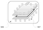
도 6은 파우치가 제거된 상태의, 도 5의 전기화학 전지 적층체를 도시한다.
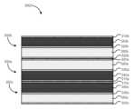
도 7은 도 6에 도시된 바와 같은 선 AA를 따라 취해진, 도 5의 도시된 전기화학 전지 적층체의 측단면도를 도시한다.
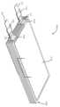
도 8은 한 실시양태에 따른, 하나의 포지티브 집전체 및 하나의 네거티브 집전체가 나머지 포지티브 및 네거티브 집전체의 탭보다 훨씬 더 긴 탭을 갖는 것인 전기화학 전지 적층체의 투시도이다.
도 9는 도 8에서 화살표 B에 의해 도시된, 도 8의 전기화학 전지 적층체의 일부분의 측면도이다.
도 10은 한 실시양태에 따른, 전기화학 전지 적층체의 형성 방법의 개략적 흐름도를 도시한다.
도 11a 내지 11i는 한 실시양태에 따른 전기화학 전지를 제조하는 공정의 단계를 도시한다.Figure 1 is a schematic diagram of an electrochemical cell according to one embodiment.
Figure 2 is a perspective view of an electrochemical cell within a pouch according to one embodiment.
Figure 3 illustrates the electrochemical cell of Figure 2 with the pouch removed.
Figure 4 is an exploded view of the electrochemical cell of Figure 3.
FIG. 5 illustrates an electrochemical cell stack within a pouch comprising a plurality of electrochemical cells according to one embodiment.
Figure 6 illustrates the electrochemical cell stack of Figure 5 with the pouch removed.
FIG. 7 is a cross-sectional side view of the electrochemical cell stack illustrated in FIG. 5 taken along line AA as illustrated in FIG. 6.
FIG. 8 is a perspective view of an electrochemical cell stack according to one embodiment, wherein one positive current collector and one negative current collector have tabs that are much longer than the tabs of the other positive and negative current collectors.
FIG. 9 is a side view of a portion of the electrochemical cell stack of FIG. 8, illustrated by arrow B in FIG. 8.
FIG. 10 illustrates a schematic flow diagram of a method for forming an electrochemical cell laminate according to one embodiment.
Figures 11a to 11i illustrate steps of a process for manufacturing an electrochemical cell according to one embodiment.
가전용 배터리는 리튬-이온 배터리 기술의 진보와 더불어 에너지 밀도가 점차 증가하고 있다. 제조된 배터리의 저장된 에너지 또는 충전 용량은 (1) 활성 물질의 고유 충전 용량 (mAh/g) (2) 전극의 부피 (㎤) (즉, 전극 두께, 전극 면적, 및 층 (적층체)의 개수의 곱), 및 (3) 전극 매질 중 활성 물질의 로딩 (예를 들어, 전극 매질 ㎤ 당 활성 물질의 그램)의 함수이다. 그러므로, 상업적 매력의 향상 (예를 들어, 증가된 에너지 밀도 및 감소된 비용)을 위해, 면적 충전 용량 (mAh/㎠)을 증가시키는 것이 일반적으로 바람직하다. 면적 충전 용량은, 예를 들어, 더 높은 고유 충전 용량을 갖는 활성 물질을 사용하고/거나, 전체 전극 배합물 중 활성 전하 저장 물질의 상대 백분율 (즉, "로딩")을 증가시키고/거나, 임의의 주어진 배터리 형태 인자에 사용되는 전극 물질의 상대 백분율을 증가시키는 것에 의해 증가될 수 있다. 달리 말해서, 활성 전하 저장 성분 (예를 들어, 전극) 대 불활성 성분 (예를 들어, 분리기 및 집전체) 비가 증가하면, 배터리의 전체 성능에 기여하지 않는 성분이 제거되거나 감소됨으로써 배터리의 전체 에너지 밀도가 증가된다. 면적 충전 용량의 증가 및 그러므로 불활성 성분의 상대 백분율의 감소를 달성하는 하나의 방안은 전극의 두께를 증가시키는 것이다.Consumer electronics batteries are seeing increasing energy densities along with advances in lithium-ion battery technology. The stored energy or charge capacity of a manufactured battery is a function of (1) the specific charge capacity of the active material (mAh/g), (2) the volume of the electrode (cm2) (i.e., the product of the electrode thickness, the electrode area, and the number of layers (laminas)), and (3) the loading of the active material into the electrode medium (e.g., grams of active material per cm2 of electrode medium). Therefore, for improved commercial attractiveness (e.g., increased energy density and reduced cost), it is generally desirable to increase the areal charge capacity (mAh/cm2). The areal charge capacity can be increased, for example, by using active materials having higher specific charge capacities, increasing the relative percentage of active charge storage material in the overall electrode formulation (i.e., "loading"), and/or increasing the relative percentage of electrode materials used in any given battery form factor. In other words, increasing the ratio of active charge storage components (e.g., electrodes) to inactive components (e.g., separator and current collector) increases the overall energy density of the battery by eliminating or reducing components that do not contribute to the overall performance of the battery. One way to achieve an increase in areal charge capacity and therefore a decrease in the relative percentage of inactive components is to increase the thickness of the electrodes.
본원에 기술된 반고체 전극은 (i) 반고체 전극의 감소된 비틀림도 및 더 높은 전자 전도도로 인해 더 두껍게 (예를 들어, 250 ㎛ 초과 내지 2,000 ㎛ 이하 또는 심지어는 그 초과로), (ii) 더 높은 활성 물질의 로딩을 갖도록, (iii) 더 적은 개수의 장비를 이용하는 단순화된 제조 공정에 의해 제조될 수 있다. 이들 반고체 전극은 고착된 또는 유동성 구조로 형성될 수 있고, 활성 성분에 대한 불활성 성분의 부피, 질량 및 비용 기여를 감소시킴으로써, 반고체 전극을 사용하여 제조한 배터리의 상업적 매력을 향상시킨다. 일부 실시양태에서, 본원에 기술된 반고체 전극은 결합제를 함유하지 않고/거나 통상의 배터리 제조에 사용되는 결합제를 사용하지 않는다. 대신에, 통상의 전극에서 결합제에 의해 통상적으로 점유되는 전극의 부피가 이제는, 1) 비틀림도를 감소시키고 이온 확산에 이용가능한 전체 염을 증가시킴으로써, 높은 비율로 사용 시에 두꺼운 통상의 전극에서 전형적인 염 고갈 효과에 대응하는 효과를 갖는 전해질, 2) 배터리의 충전 용량을 증가시키는 효과를 갖는 활성 물질, 또는 3) 전극의 전자 전도도를 증가시킴으로써, 두꺼운 통상의 전극의 높은 내부 임피던스에 대응하는 효과를 갖는 전도성 첨가제에 의해 점유된다. 본원에 기술된 반고체 전극의 감소된 비틀림도 및 더 높은 전자 전도도는 반고체 전극으로부터 형성된 전기화학 전지의 우수한 속도 역량(rate capability) 및 충전 용량을 초래한다.The semi-solid electrodes described herein can be (i) thicker (e.g., greater than 250 μm to up to or even greater than 2,000 μm) due to the reduced tortuosity and higher electronic conductivity of the semi-solid electrodes, (ii) have higher loadings of active materials, and (iii) can be manufactured by a simplified manufacturing process utilizing less equipment. These semi-solid electrodes can be formed into fixed or flowable structures, and enhance the commercial appeal of batteries manufactured using the semi-solid electrodes by reducing the volume, mass, and cost contributions of inactive components to the active component. In some embodiments, the semi-solid electrodes described herein do not contain a binder and/or do not use binders used in conventional battery manufacturing. Instead, the electrode volume normally occupied by the binder in a conventional electrode is now occupied by: 1) an electrolyte which has the effect of counteracting the salt depletion effect typical of thick conventional electrodes at high rates of use by reducing the degree of tortuosity and increasing the total salt available for ion diffusion, 2) an active material which has the effect of increasing the charge capacity of the battery, or 3) a conductive additive which has the effect of counteracting the high internal impedance of thick conventional electrodes by increasing the electronic conductivity of the electrode. The reduced degree of tortuosity and higher electronic conductivity of the semisolid electrodes described herein result in superior rate capability and charge capacity of electrochemical cells formed from the semisolid electrodes.
본원에 기술된 반고체 전극은 통상의 전극보다 훨씬 더 두껍게 제조될 수 있기 때문에, 통상의 전극을 포함하는 전기화학 전지 적층체로부터 형성된 유사한 배터리에 비해, 반고체 전극을 포함하는 전기화학 전지 적층체로부터 형성된 배터리에서 활성 물질 (즉, 반고체 캐소드 및/또는 애노드) 대 불활성 물질 (즉, 집전체 및 분리기) 비가 훨씬 더 높을 수 있다. 이로 인해 본원에 기술된 반고체 전극을 포함하는 배터리의 전체 충전 용량 및 에너지 밀도가 상당히 증가된다. 두꺼운 반고체 전극 및 그의 다양한 배합물을 이용하는 전기화학 전지의 예는 2015년 3월 31일에 허여된 발명의 명칭 "Semi-Solid Electrodes Having High Rate Capability,"의 U.S. 특허 제8,993,159호 ("'159 특허"라고도 지칭됨), 2014년 3월 10일에 출원된 발명의 명칭 "Asymmetric Battery Having a Semi-Solid Cathode and High Energy Density Anode,"의 U.S. 특허 공개 제2014/0315097호 ("'097 공개"라고도 지칭됨), 및 2014년 7월 21일에 출원된 발명의 명칭 "Semi-Solid Electrodes with Gel Polymer Additive,"의 U.S. 특허 공개 제2015/0024279호 ("'279 공개"라고도 지칭됨)에 기술되어 있고, 상기 특허 및 공개의 전체 개시 내용은 본원에 참조로 포함된다.Because the semi-solid electrodes described herein can be made much thicker than conventional electrodes, the ratio of active material (i.e., semi-solid cathode and/or anode) to inactive material (i.e., current collector and separator) in batteries formed from electrochemical cell stacks comprising the semi-solid electrodes can be much higher than in similar batteries formed from electrochemical cell stacks comprising conventional electrodes. This results in significantly increased overall charge capacity and energy density of batteries comprising the semi-solid electrodes described herein. Examples of electrochemical cells utilizing thick semi-solid electrodes and various formulations thereof are described in U.S. Pat. No. 8,993,159, issued Mar. 31, 2015, entitled "Semi-Solid Electrodes Having High Rate Capability," also referred to as the "'159 patent," and U.S. Pat. No. 8,993,159, filed Mar. 10, 2014, entitled "Asymmetric Battery Having a Semi-Solid Cathode and High Energy Density Anode," also referred to as the "'159 patent"; No. 2014/0315097 (also referred to as the "'097 publication"), and U.S. Patent Publication No. 2015/0024279 (also referred to as the "'279 publication"), entitled "Semi-Solid Electrodes with Gel Polymer Additive," filed July 21, 2014, the entire disclosures of which are incorporated herein by reference.
본원에 기술된 반고체 전극은 전해질이 슬러리 배합물에 포함되도록 슬러리로서 배합된다. 이는, 전기화학 전지가 용기, 예를 들어 파우치 또는 캔 내에 배치된 후에 전해질이 일반적으로 전기화학 전지에 첨가되는 것인 통상의 전극, 예를 들어 캘린더링된 전극과 반대된다. 반고체 전극이 더 긴 시간 동안 주위 환경에 노출되면 전해질의 증발이 촉진됨으로써, 전기화학 전지의 물리적 특성 (예를 들어, 유동성) 및/또는 전자 특성 (예를 들어, 전도도, 충전 용량, 에너지 밀도 등)이 영향받을 수 있다. 더욱이, 주위 환경 중의 수분은 또한 전해질의 성능에 나쁜 영향을 미칠 수 있다. 따라서, 전해질 증발 및/또는 열화를 제한하기 위해 가장 짧은 시간 내에, 본원에 기술된 반고체 전극을 포함하는 전기화학 전지를 조립하는 것이 유익할 것이다. 그러나, 일부 경우에, 반고체 전극을 집전체 (예를 들어, 금속 호일)의 양쪽 면 상에 배치하는 데에는 상당한 시간이 소요될 수 있다. 더욱이, 이러한 전기화학 전지로부터 전기화학 전지 적층체를 형성하기 위해, 이격자를 종종 인접한 전기화학 전지들 사이에 배치하는데, 이로 인해 전기화학 전지 내에 포함된 반고체 전극이 주위 분위기에 노출되는 시간이 추가로 증가될 수 있다.The semi-solid electrodes described herein are formulated as a slurry such that the electrolyte is incorporated into the slurry composition. This is in contrast to conventional electrodes, such as calendared electrodes, in which the electrolyte is typically added to the electrochemical cell after the electrochemical cell has been placed in a container, such as a pouch or can. If the semi-solid electrode is exposed to the ambient environment for a longer period of time, the evaporation of the electrolyte may be accelerated, thereby affecting the physical properties (e.g., flowability) and/or electronic properties (e.g., conductivity, charge capacity, energy density, etc.) of the electrochemical cell. Furthermore, moisture in the ambient environment may also adversely affect the performance of the electrolyte. Therefore, it would be advantageous to assemble the electrochemical cell comprising the semi-solid electrodes described herein in the shortest possible time to limit electrolyte evaporation and/or degradation. However, in some cases, it may take a significant amount of time to place the semi-solid electrode on both sides of the current collector (e.g., a metal foil). Moreover, to form an electrochemical cell stack from these electrochemical cells, a spacer is often placed between adjacent electrochemical cells, which may further increase the time that the semi-solid electrodes contained within the electrochemical cell are exposed to the surrounding atmosphere.
본원에 기술된 전기화학 전지의 실시양태는 집전체의 한쪽 면 상에만 코팅된 반고체 전극을 포함한다. 집전체의 한쪽 면 상에만 코팅을 하면 집전체의 양쪽 면 상에 코팅하는 것과 연관된 시간뿐만 아니라 제조상 복잡성이 감소한다. 이어서, 인접한 전기화학 전지의 집전체들이 서로 맞닿도록 전기화학 전지를 적층함으로써, 전기화학 전지 적층체를 쉽게 형성할 수 있다. 예를 들어, 제1 전기화학 전지 내에 포함된 포지티브 집전체의 코팅되지 않은 면은 제2 전기화학 전지 내에 포함된 포지티브 집전체의 코팅되지 않은 면과 맞닿을 수 있다. 마찬가지로, 제1 전기화학 전지 내에 포함된 네거티브 집전체의 코팅되지 않은 면은 제3 전기화학 전지 내에 포함된 네거티브 집전체의 코팅되지 않은 면과 맞닿을 수 있고, 기타 등등이다. 이로 인해 전기화학 전지 적층체의 형성에 사용되는 시간이 추가로 감소됨으로써, 전극이 주위 환경에 노출되는 것이 최소화될 수 있다. 전기화학 전지를 형성하는 데 요구되는 짧은 조립 시간으로 인해 또한 전해질 증발이 감소되고/거나 물 투과로 인한 반고체 전극의 열화가 또한 최소화될 수 있다.Embodiments of the electrochemical cell described herein include a semi-solid electrode coated on only one side of a current collector. Coating only on one side of the current collector reduces the time and manufacturing complexity associated with coating both sides of the current collector. An electrochemical cell stack can then be readily formed by stacking the electrochemical cells such that the current collectors of adjacent electrochemical cells are in contact with each other. For example, the uncoated side of the positive current collector included in a first electrochemical cell can be in contact with the uncoated side of the positive current collector included in a second electrochemical cell. Similarly, the uncoated side of the negative current collector included in the first electrochemical cell can be in contact with the uncoated side of the negative current collector included in a third electrochemical cell, and so on. This further reduces the time required to form the electrochemical cell stack, thereby minimizing exposure of the electrodes to the ambient environment. The short assembly time required to form the electrochemical cell may also result in reduced electrolyte evaporation and/or minimal degradation of the semi-solid electrode due to water permeation.
일부 실시양태에서, 전기화학 전지는 포지티브 집전체의 한쪽 면 상에만 코팅된 반고체 포지티브 전극 및 네거티브 집전체의 한쪽 면 상에만 코팅된 반고체 네거티브 전극을 포함한다. 이온-투과성 멤브레인이 반고체 포지티브 전극과 반고체 네거티브 전극 사이에 배치된다. 반고체 포지티브 전극 및 반고체 네거티브 전극 중 적어도 하나는 적어도 약 250 ㎛의 두께를 갖는다. 일부 실시양태에서, 포지티브 집전체 및/또는 네거티브 집전체는 금속 호일, 예를 들어, 알루미늄 호일 또는 구리 호일을 포함할 수 있다. 일부 실시양태에서, 전기화학 전지는 진공 밀봉된 파우치 내에 배치될 수 있다.In some embodiments, the electrochemical cell comprises a semi-solid positive electrode coated only on one side of a positive current collector and a semi-solid negative electrode coated only on one side of a negative current collector. An ion-permeable membrane is disposed between the semi-solid positive electrode and the semi-solid negative electrode. At least one of the semi-solid positive electrode and the semi-solid negative electrode has a thickness of at least about 250 μm. In some embodiments, the positive current collector and/or the negative current collector can comprise a metal foil, such as aluminum foil or copper foil. In some embodiments, the electrochemical cell can be disposed within a vacuum-sealed pouch.
일부 실시양태에서, 전기화학 전지 적층체의 형성 방법은 반고체 캐소드를 포지티브 집전체의 한쪽 면 상에만 코팅하고 반고체 애노드를 네거티브 집전체의 한쪽 면 상에만 코팅하는 것을 포함한다. 분리기를 반고체 캐소드와 반고체 애노드 사이에 배치하여 제1 전기화학 전지를 형성한다. 제2 전기화학 전지를 제1 전기화학 전지와 상당히 유사하게 형성한다. 게다가, 제3 전기화학 전지를 제1 전기화학 전지와 상당히 유사하게 형성하고, 기타 등등이다. 제2 전기화학 전지의 포지티브 집전체의 코팅되지 않은 면이 제1 전기화학 전지의 포지티브 집전체의 코팅되지 않은 면 상에 배치되도록 제2 전기화학 전지를 제1 전기화학 전지 상에 배치한다. 마찬가지로, 제3 전기화학 전지의 네거티브 집전체의 코팅되지 않은 면이 제1 전기화학 전지의 네거티브 집전체의 코팅되지 않은 면 상에 배치되도록 제3 전기화학 전지를 제1 전기화학 전지 상에 배치함으로써, 전기화학 전지 적층체를 형성한다. 일부 실시양태에서, 임의의 제1 전기화학 전지, 제2 전기화학 전지, 및 제3 전기화학 전지의 반고체 캐소드 및/또는 반고체 애노드 내에 포함된 전해질의 증발이 최소화되도록, 전기화학 전지 적층체를 형성하는 데 요구되는 시간이 충분히 감소될 수 있다.In some embodiments, a method of forming an electrochemical cell stack comprises coating a semi-solid cathode on only one side of a positive current collector and coating a semi-solid anode on only one side of a negative current collector. A separator is disposed between the semi-solid cathode and the semi-solid anode to form a first electrochemical cell. A second electrochemical cell is formed substantially similar to the first electrochemical cell. Furthermore, a third electrochemical cell is formed substantially similar to the first electrochemical cell, and so on. The second electrochemical cell is disposed on the first electrochemical cell such that the uncoated side of the positive current collector of the second electrochemical cell is disposed on the uncoated side of the positive current collector of the first electrochemical cell. Similarly, the third electrochemical cell is disposed on the first electrochemical cell such that the uncoated side of the negative current collector of the third electrochemical cell is disposed on the uncoated side of the negative current collector of the first electrochemical cell, thereby forming an electrochemical cell stack. In some embodiments, the time required to form the electrochemical cell stack can be sufficiently reduced such that evaporation of the electrolyte contained within the semi-solid cathode and/or semi-solid anode of any of the first electrochemical cell, the second electrochemical cell, and the third electrochemical cell is minimized.
반고체 전극의 혼합 및 형성은 일반적으로 (i) 원료 이송 및/또는 공급, (ii) 혼합, (iii) 혼합된 슬러리 이송, (iv) 분배 및/또는 압출, 및 (v) 형성을 포함한다. 일부 실시양태에서, 공정의 여러 단계를 동시에 및/또는 동일한 장비를 사용하여 수행할 수 있다. 예를 들어, 혼합 및 슬러리의 이송을 동시에 압출기를 사용하여 수행할 수 있다. 공정의 각각의 단계는 하나 이상의 가능한 실시양태를 포함할 수 있다. 예를 들어, 공정의 각각의 단계를 수동으로 또는 임의의 다양한 공정 장비를 사용하여 수행할 수 있다. 각각의 단계는 또한 하나 이상의 부-공정(sub-process), 및 임의로, 공정 품질을 모니터링하기 위한 검사 단계를 포함할 수 있다.Mixing and forming a semi-solid electrode generally comprises (i) conveying and/or feeding raw materials, (ii) mixing, (iii) conveying the mixed slurry, (iv) dispensing and/or extruding, and (v) forming. In some embodiments, several steps of the process can be performed simultaneously and/or using the same equipment. For example, mixing and conveying the slurry can be performed simultaneously using an extruder. Each step of the process can include one or more possible embodiments. For example, each step of the process can be performed manually or using any of a variety of process equipment. Each step can also include one or more sub-processes, and optionally, inspection steps to monitor process quality.
일부 실시양태에서, 공정 조건은 적어도 약 0.80, 적어도 약 0.90, 적어도 약 0.95, 또는 적어도 약 0.975의 혼합 지수를 갖는 제조 슬러리가 제조되도록 선택될 수 있다. 일부 실시양태에서, 공정 조건은 적어도 약 10-6 S/cm, 적어도 약 10-5 S/cm, 적어도 약 10-4 S/cm, 적어도 약 10-3 S/cm, 또는 적어도 약 10-2 S/cm의 전자 전도도를 갖는 제조 슬러리가 생성되도록 선택될 수 있다. 일부 실시양태에서, 공정 조건은 1,000 s-1의 겉보기 전단 속도에서 약 100,000 Pa-s 미만, 약 10,000 Pa-s 미만, 또는 약 1,000 Pa-s 미만의 실온에서의 겉보기 점도를 갖는 제조 슬러리가 제조되도록 선택될 수 있다. 일부 실시양태에서, 공정 조건은 본원에 기술된 바와 같은 둘 이상의 특성을 갖는 제조 슬러리가 제조되도록 선택될 수 있다. 본원에 기술된 반고체 전극 조성물을 제조하는 데 사용될 수 있는 시스템 및 방법의 예는 2013년 3월 15일에 출원된 발명의 명칭 "Electrochemical Slurry Compositions and Methods for Preparing the Same"의 U.S. 특허 공개 제2013/0337319호 ("'319 공개"라고도 지칭됨)에 기술되어 있으며, 상기 공개의 전체 개시 내용은 본원에 참조로 포함된다.In some embodiments, the process conditions can be selected to produce a manufactured slurry having a mixing index of at least about 0.80, at least about 0.90, at least about 0.95, or at least about 0.975. In some embodiments, the process conditions can be selected to produce a manufactured slurry having an electronic conductivity of at least about 10-6 S/cm, at least about 10-5 S/cm, at least about 10-4 S/cm, at least about 10-3 S/cm, or at least about 10-2 S/cm . In some embodiments, the process conditions can be selected to produce a manufactured slurry having an apparent viscosity at room temperature of less than about 100,000 Pa-s, less than about 10,000 Pa-s, or less than about 1,000 Pa-s at an apparent shear rate of 1,000 s -1 . In some embodiments, the process conditions can be selected to produce a manufactured slurry having two or more properties as described herein. Examples of systems and methods that can be used to prepare the semi-solid electrode compositions described herein are described in US Patent Publication No. 2013/0337319, filed March 15, 2013, entitled "Electrochemical Slurry Compositions and Methods for Preparing the Same" (also referred to as the "'319 publication"), the entire disclosure of which is incorporated herein by reference.
본원에 사용된 용어 "약" 및 "대략"은 일반적으로 언급된 값의 플러스 또는 마이너스 10%를 의미하고, 예를 들어 약 250 ㎛는 225 ㎛ 내지 275 ㎛를 포함할 것이고, 약 1,000 ㎛는 900 ㎛ 내지 1,100 ㎛를 포함할 것이다.The terms “about” and “approximately” as used herein generally mean plus or minus 10% of the stated value, for example, about 250 μm would include from 225 μm to 275 μm, and about 1,000 μm would include from 900 μm to 1,100 μm.
본원에 사용된 용어 "반고체"는, 액체상과 고체상의 혼합물인 물질, 예를 들어, 예컨대, 입자 현탁액, 콜로이드성 현탁액, 에멀젼, 겔, 또는 미셀을 지칭한다.The term "semisolid" as used herein refers to a material which is a mixture of liquid and solid phases, for example, a particle suspension, a colloidal suspension, an emulsion, a gel, or micelles.
본원에 사용된 용어 "활성화된 탄소 네트워크" 및 "네트워크화된 탄소"는 전극의 일반적인 정성적 상태에 관한 것이다. 예를 들어, 활성화된 탄소 네트워크 (또는 네트워크화된 탄소)를 갖는 전극은, 전극 내의 탄소 입자가 입자들 사이에서 전극의 두께 및 길이를 통한 전기적 접촉 및 전기 전도를 용이하게 하는 개별 입자 모폴로지 및 서로에 대한 배열을 갖도록 한 것이다. 역으로, 용어 "불활성화된 탄소 네트워크" 및 "비-네트워크화된 탄소"는 탄소 입자가 전극을 통한 적절한 전기 전도를 제공하도록 충분히 연결되지는 않을 수 있는 개별 입자 섬(island) 또는 다중-입자 응결 섬으로서 존재하는 것인 전극에 관한 것이다.The terms "activated carbon network" and "networked carbon" as used herein relate to the general qualitative state of the electrode. For example, an electrode having an activated carbon network (or networked carbon) is one in which the carbon particles within the electrode have an individual particle morphology and arrangement relative to one another that facilitates electrical contact and electrical conduction between the particles throughout the thickness and length of the electrode. Conversely, the terms "deactivated carbon network" and "non-networked carbon" relate to an electrode in which the carbon particles exist as individual particle islands or multi-particle agglomerated islands that may not be sufficiently interconnected to provide adequate electrical conduction through the electrode.
도 1은 전기화학 전지(100)의 개략적 도해를 도시한다. 전기화학 전지(100)는 포지티브 집전체(110) 및 네거티브 집전체(120)를 포함한다. 반고체 캐소드(140)는 포지티브 집전체(110) 상에 배치되고, 반고체 애노드(150)는 네거티브 집전체(120) 상에 배치된다. 분리기(130)는 반고체 캐소드(140)와 반고체 애노드(150) 사이에 배치된다. 반고체 캐소드(140)와 반고체 애노드(150) 중 적어도 하나는 적어도 약 250 ㎛, 예를 들어, 약 250 ㎛ 내지 약 2,000 ㎛의 범위의 두께를 갖는다.FIG. 1 illustrates a schematic diagram of an electrochemical cell (100). The electrochemical cell (100) includes a positive current collector (110) and a negative current collector (120). A semi-solid cathode (140) is disposed on the positive current collector (110), and a semi-solid anode (150) is disposed on the negative current collector (120). A separator (130) is disposed between the semi-solid cathode (140) and the semi-solid anode (150). At least one of the semi-solid cathode (140) and the semi-solid anode (150) has a thickness of at least about 250 μm, for example, in a range of about 250 μm to about 2,000 μm.
포지티브 집전체(110) 및 네거티브 집전체(120)는 전자 전도성이며 전지의 작동 조건 하에 전기화학적으로 불활성인 임의의 집전체일 수 있다. 리튬 전지를 위한 전형적인 집전체는 네거티브 집전체(120)의 경우에 구리, 알루미늄, 또는 티타늄, 및 포지티브 집전체(110)의 경우에 알루미늄을 시트 또는 메쉬 또는 그의 임의의 조합의 형태로 포함한다. 집전체 물질은 전기화학 전지(100)의 반고체 캐소드(140) 및 반고체 애노드(150)의 작동 전위에서 안정하도록 선택될 수 있다. 예를 들어, 비-수성 리튬 시스템에서, 포지티브 집전체(110)는 알루미늄, 또는 Li/Li+에 대해 2.5 내지 5.0 V의 작동 전위에서 전기화학적으로 용해되지 않는 전도성 물질로 코팅된 알루미늄을 포함할 수 있다. 이러한 물질은 백금, 금, 니켈, 전도성 금속 산화물, 예컨대 산화바나듐, 및 탄소를 포함한다. 네거티브 집전체(120)는 구리를 포함할 수 있거나, 리튬, 탄소 및/또는 또 다른 전도체 상에 배치된 이러한 물질을 포함하는 코팅과 합금 또는 금속간 화합물을 형성하지 않는 다른 금속을 포함할 수 있다. 각각의 포지티브 집전체(110) 및 네거티브 집전체(120)는 약 20 마이크로미터 미만, 예를 들어, 약 1 마이크로미터, 2 마이크로미터, 3 마이크로미터, 4 마이크로미터, 5 마이크로미터, 6 마이크로미터, 7 마이크로미터, 8 마이크로미터, 9 마이크로미터, 10 마이크로미터, 12 마이크로미터, 14 마이크로미터, 16 마이크로미터, 또는 18 마이크로미터 (그들 사이의 모든 범위를 포함함)의 두께를 가질 수 있다. 이러한 얇은 포지티브 집전체(110) 및 네거티브 집전체(120)를 사용하면 전기화학 전지(100)의 비용 및 전체 중량이 상당히 감소될 수 있다.The positive current collector (110) and the negative current collector (120) can be any current collector that is electronically conductive and electrochemically inactive under the operating conditions of the cell. Typical current collectors for lithium cells include copper, aluminum, or titanium for the negative current collector (120), and aluminum for the positive current collector (110) in the form of sheets or mesh or any combination thereof. The current collector materials can be selected to be stable at the operating potentials of the semi-solid cathode (140) and the semi-solid anode (150) of the electrochemical cell (100). For example, in non-aqueous lithium systems, the positive current collector (110) can include aluminum, or aluminum coated with a conductive material that is electrochemically insoluble at an operating potential of 2.5 to 5.0 V vs. Li/Li+ . Such materials include platinum, gold, nickel, conductive metal oxides such as vanadium oxide, and carbon. The negative current collector (120) may include copper, or may include a coating comprising such materials disposed on the lithium, carbon, and/or another conductor and other metals that do not form an alloy or intermetallic compound. Each of the positive current collector (110) and the negative current collector (120) may have a thickness of less than about 20 micrometers, for example, about 1 micrometer, 2 micrometers, 3 micrometers, 4 micrometers, 5 micrometers, 6 micrometers, 7 micrometers, 8 micrometers, 9 micrometers, 10 micrometers, 12 micrometers, 14 micrometers, 16 micrometers, or 18 micrometers (including all ranges therebetween). Using such thin positive current collectors (110) and negative current collectors (120) can significantly reduce the cost and overall weight of the electrochemical cell (100).
전기화학 전지(100) 내에 포함된 반고체 캐소드(140)와 반고체 애노드(150)는 분리기(130)에 의해 분리된다. 분리기(130)는 이온 수송을 할 수 있는 임의의 통상의 멤브레인, 즉 이온-투과성 멤브레인일 수 있다. 일부 실시양태에서, 분리기(130)는 그를 통한 이온의 수송을 허용하는 액체 불투과성 멤브레인, 즉 고체 또는 겔 이온 전도체이다. 일부 실시양태에서, 분리기(130)는, 반고체 캐소드(140) 전기활성 물질과 반고체 애노드(150) 전기활성 물질 사이의 이온의 왕복을 허용하면서도 전자의 전달을 방지하는, 액체 전해질이 주입된 다공성 중합체 멤브레인이다. 일부 실시양태에서, 분리기(130)는 반고체 캐소드(140) 및 반고체 애노드(150) 조성물을 형성하는 입자가 멤브레인을 횡단하는 것을 방지하는 미세다공성 멤브레인이다. 일부 실시양태에서, 분리기(130)는, 임의로 특정 온도 초과에서 융해 또는 "폐쇄"되어 더 이상 작동 이온을 투과시키지 않는 능력을 갖는, 리튬 이온 배터리 산업에서 사용되고 관련 기술분야의 통상의 기술자에게 널리 공지된 유형의 단일 또는 다층 미세다공성 분리기이다. 일부 실시양태에서, 분리기(130)는, 리튬 염이 착화되어 리튬 전도도를 제공하는 것인 폴리에틸렌옥시드 (PEO) 중합체, 또는 양성자 전도체인 나피온(Nafion)™ 멤브레인을 포함할 수 있다. 예를 들어, PEO 기재의 전해질이 분리기(130)로서 사용될 수 있고, 이는, 임의로 지지 층으로서의 유리 섬유 분리기와 같은 다른 멤브레인에 의해 안정화된, 핀홀-비함유 고체 이온 전도체이다. PEO는 또한 포지티브 또는 네거티브 전극 산화환원 조성물에서 슬러리 안정화제, 분산제 등으로서 사용될 수 있다. PEO는 전형적인 알킬 카르보네이트-기재의 전해질과 접촉 시에 안정하다. 이는 특히, Li 금속에 대해 약 3.6 V 미만인 포지티브 전극에서의 전지 전위를 갖는 인산염-기재의 전지 화학에서 유용할 수 있다. 산화환원 전지의 작동 온도는 멤브레인의 이온 전도도를 개선하기 위해 필요에 따라 상승될 수 있다.A semi-solid cathode (140) and a semi-solid anode (150) included in the electrochemical cell (100) are separated by a separator (130). The separator (130) can be any conventional membrane capable of ion transport, i.e., an ion-permeable membrane. In some embodiments, the separator (130) is a liquid-impermeable membrane, i.e., a solid or gel ion conductor, that allows transport of ions therethrough. In some embodiments, the separator (130) is a porous polymer membrane impregnated with a liquid electrolyte that allows the shuttling of ions between the semi-solid cathode (140) electroactive material and the semi-solid anode (150) electroactive material while preventing the transfer of electrons. In some embodiments, the separator (130) is a microporous membrane that prevents particles forming the semi-solid cathode (140) and semi-solid anode (150) compositions from traversing the membrane. In some embodiments, the separator (130) is a single or multilayer microporous separator of the type used in the lithium ion battery industry and well known to those skilled in the art, optionally having the ability to melt or "close" above a certain temperature and no longer permeate the operating ions. In some embodiments, the separator (130) can include a polyethylene oxide (PEO) polymer, which is a lithium salt complexed to provide lithium conductivity, or a Nafion™ membrane, which is a proton conductor. For example, a PEO-based electrolyte can be used as the separator (130), which is a pinhole-free solid ion conductor, optionally stabilized by another membrane, such as a glass fiber separator as a support layer. PEO can also be used as a slurry stabilizer, dispersant, etc. in positive or negative electrode redox compositions. PEO is stable in contact with typical alkyl carbonate-based electrolytes. This may be particularly useful in phosphate-based cell chemistries having cell potentials at the positive electrode of less than about 3.6 V vs. Li metal. The operating temperature of the redox cell can be increased as needed to improve the ionic conductivity of the membrane.
반고체 캐소드(140)는, 예를 들어, 활성 물질 및/또는 전도성 물질을 포함할 수 있는 이온-저장 고체상 물질을 포함할 수 있다. 이온-저장 고체상 물질의 양은 약 0 부피% 내지 약 80 부피%의 범위일 수 있다. 캐소드(140)는 활성 물질, 예컨대, 예를 들어, 리튬 보유 화합물 (예를 들어, 리튬 철 인산염 (LFP), LiCoO2, Mg로 도핑된 LiCoO2, LiNiO2, Li(Ni, Co, Al)O2 ("NCA"로서 공지됨), Li(Ni, Mn, Co)O2 ("NMC"로서 공지됨), LiMn2O4 및 그것의 유도체 등)을 포함할 수 있다. 캐소드(140)는 또한 전도성 물질, 예컨대, 예를 들어, 흑연, 탄소 분말, 열분해 탄소, 카본블랙, 탄소 섬유, 탄소 마이크로섬유, 탄소 나노튜브 (CNT), 단일벽 CNT, 다중벽 CNT, "버키 볼(bucky ball)"을 포함하는 풀러렌 탄소, 그래핀 시트 및/또는 그래핀 시트의 응집체, 임의의 다른 전도성 물질, 그의 합금 또는 조합을 포함할 수 있다. 캐소드(140)는 또한 비-수성 액체 전해질, 예컨대, 예를 들어, 에틸렌 카르보네이트, 디메틸 카르보네이트, 디에틸 카르보네이트, SSDE, 또는 본원에 기술된 임의의 다른 전해질 또는 그의 조합을 포함할 수 있다.The semi-solid cathode (140) can include, for example, an ion-storing solid material, which can include an active material and/or a conductive material. The amount of the ion-storing solid material can range from about 0 volume % to about 80 volume %. The cathode (140) can include an active material, such as, for example, a lithium-containing compound (e.g., lithium iron phosphate (LFP), LiCoO2 , Mg-doped LiCoO2 , LiNiO2 , Li(Ni, Co, Al)O2 (known as "NCA"), Li(Ni, Mn, Co)O2 (known as "NMC"), LiMn2 O4 and derivatives thereof, etc.). The cathode (140) may also include a conductive material, such as, for example, graphite, carbon powder, pyrolytic carbon, carbon black, carbon fibers, carbon microfibers, carbon nanotubes (CNTs), single-walled CNTs, multi-walled CNTs, fullerene carbons including "bucky balls", graphene sheets and/or aggregates of graphene sheets, any other conductive material, alloys or combinations thereof. The cathode (140) may also include a non-aqueous liquid electrolyte, such as, for example, ethylene carbonate, dimethyl carbonate, diethyl carbonate, SSDE, or any other electrolyte described herein or combinations thereof.
일부 실시양태에서, 반고체 애노드(150)는 또한, 예를 들어, 활성 물질 및/또는 전도성 물질을 포함할 수 있는 이온-저장 고체상 물질을 포함할 수 있다. 이온-저장 고체상 물질의 양은 약 0 부피% 내지 약 80 부피%의 범위일 수 있다. 반고체 애노드(150)는 애노드 활성 물질, 예컨대, 예를 들어, 리튬 금속, 탄소, 리튬-삽입된 탄소, 질화리튬, 리튬 합금, 및 규소, 비스무트, 붕소, 갈륨, 인듐, 아연, 주석, 산화주석, 안티모니, 알루미늄, 산화티타늄, 몰리브데넘, 게르마늄, 망가니즈, 니오븀, 바나듐, 탄탈럼, 금, 백금, 철, 구리, 크로뮴, 니켈, 코발트, 지르코늄, 이트륨, 산화몰리브데넘, 산화게르마늄, 산화규소, 탄화규소의 리튬 합금 형성 화합물, 임의의 다른 물질 또는 그의 합금, 및 그의 임의의 다른 조합을 포함할 수 있다.In some embodiments, the semi-solid anode (150) may also include an ion-storing solid material, which may include, for example, an active material and/or a conductive material. The amount of the ion-storing solid material may range from about 0 vol % to about 80 vol %. The semi-solid anode (150) can include an anode active material, such as, for example, lithium metal, carbon, lithium-intercalated carbon, lithium nitride, a lithium alloy, and a lithium alloy forming compound of silicon, bismuth, boron, gallium, indium, zinc, tin, tin oxide, antimony, aluminum, titanium oxide, molybdenum, germanium, manganese, niobium, vanadium, tantalum, gold, platinum, iron, copper, chromium, nickel, cobalt, zirconium, yttrium, molybdenum oxide, germanium oxide, silicon oxide, silicon carbide, any other material or alloy thereof, and any other combination thereof.
반고체 애노드(150)는 또한 탄소질 물질, 예컨대, 예를 들어, 흑연, 탄소 분말, 열분해 탄소, 카본블랙, 탄소 섬유, 탄소 마이크로섬유, 탄소 나노튜브 (CNT), 단일벽 CNT, 다중벽 CNT, "버키 볼"을 포함하는 풀러렌 탄소, 그래핀 시트 및/또는 그래핀 시트의 응집체, 임의의 다른 탄소질 물질 또는 그의 조합일 수 있는 전도성 물질을 포함할 수 있다. 일부 실시양태에서, 반고체 애노드(150)는 또한 비-수성 액체 전해질, 예컨대, 예를 들어, 에틸렌 카르보네이트, 디메틸 카르보네이트, 디에틸 카르보네이트, 또는 본원에 기술된 임의의 다른 전해질 또는 그의 조합을 포함할 수 있다.The semi-solid anode (150) may also include a conductive material, which may be a carbonaceous material, such as, for example, graphite, carbon powder, pyrolytic carbon, carbon black, carbon fibers, carbon microfibers, carbon nanotubes (CNTs), single-walled CNTs, multi-walled CNTs, fullerene carbons including “bucky balls,” graphene sheets and/or aggregates of graphene sheets, any other carbonaceous material, or combinations thereof. In some embodiments, the semi-solid anode (150) may also include a non-aqueous liquid electrolyte, such as, for example, ethylene carbonate, dimethyl carbonate, diethyl carbonate, or any other electrolyte described herein, or combinations thereof.
일부 실시양태에서, 반고체 캐소드(140) 및/또는 반고체 애노드(150)는 활성 물질 및 임의로 전도성 물질을 비-수성 액체 전해질 중에 현탁된 미립자 형태로 포함할 수 있다. 일부 실시양태에서, 반고체 캐소드(140) 및/또는 반고체 애노드(150) 입자 (예를 들어, 캐소드 또는 애노드 입자)는 적어도 약 1 ㎛의 유효 직경을 가질 수 있다. 일부 실시양태에서, 캐소드 또는 애노드 입자는 약 1 ㎛ 내지 약 10 ㎛의 유효 직경을 갖는다. 일부 실시양태에서, 캐소드 또는 애노드 입자는 적어도 약 10 ㎛ 이상의 유효 직경을 갖는다. 일부 실시양태에서, 캐소드 또는 애노드 입자는 약 1 ㎛ 미만의 유효 직경을 갖는다. 일부 실시양태에서, 캐소드 또는 애노드 입자는 약 0.5 ㎛ 미만의 유효 직경을 갖는다. 일부 실시양태에서, 캐소드 또는 애노드 입자는 약 0.25 ㎛ 미만의 유효 직경을 갖는다. 일부 실시양태에서, 캐소드 또는 애노드 입자는 약 0.1 ㎛ 미만의 유효 직경을 갖는다. 일부 실시양태에서, 캐소드 또는 애노드 입자는 약 0.05 ㎛ 미만의 유효 직경을 갖는다. 다른 실시양태에서, 캐소드 또는 애노드 입자는 약 0.01 ㎛ 미만의 유효 직경을 갖는다.In some embodiments, the semi-solid cathode (140) and/or semi-solid anode (150) can comprise active material and optionally conductive material in particulate form suspended in a non-aqueous liquid electrolyte. In some embodiments, the semi-solid cathode (140) and/or semi-solid anode (150) particles (e.g., cathode or anode particles) can have an effective diameter of at least about 1 μm. In some embodiments, the cathode or anode particles have an effective diameter of from about 1 μm to about 10 μm. In some embodiments, the cathode or anode particles have an effective diameter of at least about 10 μm or greater. In some embodiments, the cathode or anode particles have an effective diameter less than about 1 μm. In some embodiments, the cathode or anode particles have an effective diameter less than about 0.5 μm. In some embodiments, the cathode or anode particles have an effective diameter less than about 0.25 μm. In some embodiments, the cathode or anode particles have an effective diameter of less than about 0.1 μm. In some embodiments, the cathode or anode particles have an effective diameter of less than about 0.05 μm. In other embodiments, the cathode or anode particles have an effective diameter of less than about 0.01 μm.
일부 실시양태에서, 반고체 캐소드(140)는 약 20% 내지 약 80 부피%의 활성 물질을 포함할 수 있다. 일부 실시양태에서, 반고체 캐소드(140)는 약 40 부피% 내지 약 75 부피%, 약 50 부피% 내지 약 75 부피%, 약 60 부피% 내지 약 75 부피%, 또는 약 60 부피% 내지 약 80 부피%의 활성 물질을 포함할 수 있다.In some embodiments, the semi-solid cathode (140) can comprise about 20% to about 80% by volume of active material. In some embodiments, the semi-solid cathode (140) can comprise about 40% to about 75% by volume, about 50% to about 75% by volume, about 60% to about 75% by volume, or about 60% to about 80% by volume of active material.
일부 실시양태에서, 반고체 캐소드(140)는 약 0 부피% 내지 약 25 부피%의 전도성 물질을 포함할 수 있다. 일부 실시양태에서, 반고체 캐소드(140)는 약 1.0 부피% 내지 약 6 부피%, 약 6 부피% 내지 약 12 부피%, 또는 약 2 부피% 내지 약 15 부피%의 전도성 물질을 포함할 수 있다.In some embodiments, the semi-solid cathode (140) can comprise from about 0 vol % to about 25 vol % of the conductive material. In some embodiments, the semi-solid cathode (140) can comprise from about 1.0 vol % to about 6 vol %, from about 6 vol % to about 12 vol %, or from about 2 vol % to about 15 vol % of the conductive material.
일부 실시양태에서, 반고체 캐소드(140)는 약 20 부피% 내지 약 70 부피%의 전해질을 포함할 수 있다. 일부 실시양태에서, 반고체 캐소드(140)는 약 30 부피% 내지 약 60 부피%, 약 40 부피% 내지 약 50 부피%, 또는 약 20 부피% 내지 약 40 부피%의 전해질을 포함할 수 있다.In some embodiments, the semi-solid cathode (140) can comprise about 20 vol % to about 70 vol % of the electrolyte. In some embodiments, the semi-solid cathode (140) can comprise about 30 vol % to about 60 vol %, about 40 vol % to about 50 vol %, or about 20 vol % to about 40 vol % of the electrolyte.
일부 실시양태에서, 반고체 애노드(150)는 약 20 부피% 내지 약 80 부피%의 활성 물질을 포함할 수 있다. 일부 실시양태에서, 반고체 애노드(150)는 약 40 부피% 내지 약 75 부피%, 약 50 부피% 내지 약 75 부피%, 약 60 부피% 내지 약 75 부피%, 또는 약 60 부피% 내지 약 80 부피%의 활성 물질을 포함할 수 있다.In some embodiments, the semi-solid anode (150) can comprise from about 20 vol % to about 80 vol % of active material. In some embodiments, the semi-solid anode (150) can comprise from about 40 vol % to about 75 vol %, from about 50 vol % to about 75 vol %, from about 60 vol % to about 75 vol %, or from about 60 vol % to about 80 vol % of active material.
일부 실시양태에서, 반고체 애노드(150)는 약 0 부피% 내지 약 20 부피%의 전도성 물질을 포함할 수 있다. 일부 실시양태에서, 반고체 애노드(150)는 약 1 부피% 내지 약 10 부피%, 1 부피% 내지 약 6 부피%, 약 0.5 부피% 내지 약 2 부피%, 약 2 부피% 내지 약 6 부피%, 또는 약 2 부피% 내지 약 4 부피%의 전도성 물질을 포함할 수 있다.In some embodiments, the semi-solid anode (150) can comprise from about 0 vol % to about 20 vol % of the conductive material. In some embodiments, the semi-solid anode (150) can comprise from about 1 vol % to about 10 vol %, from 1 vol % to about 6 vol %, from about 0.5 vol % to about 2 vol %, from about 2 vol % to about 6 vol %, or from about 2 vol % to about 4 vol % of the conductive material.
일부 실시양태에서, 반고체 애노드(150)는 약 20 부피% 내지 약 70 부피%의 전해질을 포함할 수 있다. 일부 실시양태에서, 반고체 애노드(150)는 약 30 부피% 내지 약 60 부피%, 약 40 부피% 내지 약 50 부피%, 또는 약 20 부피% 내지 약 40 부피%의 전해질을 포함할 수 있다.In some embodiments, the semi-solid anode (150) can comprise about 20 vol % to about 70 vol % of the electrolyte. In some embodiments, the semi-solid anode (150) can comprise about 30 vol % to about 60 vol %, about 40 vol % to about 50 vol %, or about 20 vol % to about 40 vol % of the electrolyte.
반고체 캐소드(140) 및/또는 반고체 애노드(150) 조성물, 그의 다양한 배합물, 및 그로부터 형성된 전기화학 전지에서 사용될 수 있는 활성 물질, 전도성 물질, 및/또는 전해질의 예는 '159 특허, 2014년 5월 13일에 허여된 발명의 명칭 "High Energy Density Redox Flow Device"의 U.S. 특허 제8,722,226호 ("226 특허"라고도 지칭됨) 및 2010년 12월 16일에 출원된 발명의 명칭 "High Energy Density Redox Flow Device"의 U.S. 특허 공개 제2011/0200848호 ("'848 공개"라고도 지칭됨)에 기술되어 있고, 상기 특허 및 공개의 전체 개시 내용은 본원에 참조로 포함된다.Examples of active materials, conductive materials, and/or electrolytes that can be used in the semi-solid cathode (140) and/or semi-solid anode (150) compositions, various combinations thereof, and electrochemical cells formed therefrom are described in the '159 patent, U.S. Pat. No. 8,722,226, entitled "High Energy Density Redox Flow Device," issued May 13, 2014 (also referred to as the "'226 patent"), and U.S. Patent Publication No. 2011/0200848, entitled "High Energy Density Redox Flow Device," filed December 16, 2010 (also referred to as the "'848 publication"), the entire disclosures of which are incorporated herein by reference.
일부 실시양태에서, 반고체 애노드(150)는 또한 약 1 부피% 내지 약 30 부피%의 고용량 물질을 포함할 수 있다. 이러한 고용량 물질은, 예를 들어, 규소, 비스무트, 붕소, 갈륨, 인듐, 아연, 주석, 안티모니, 알루미늄, 산화티타늄, 몰리브데넘, 게르마늄, 망가니즈, 니오븀, 바나듐, 탄탈럼, 철, 구리, 금, 백금, 크로뮴, 니켈, 코발트, 지르코늄, 이트륨, 산화몰리브데넘, 산화게르마늄, 산화규소, 탄화규소, 임의의 다른 고용량 물질 또는 그의 합금, 및 그의 임의의 조합을 포함할 수 있다. 일부 실시양태에서, 반고체는 약 1 부피% 내지 약 5 부피%, 약 1 부피% 내지 약 10 부피%, 또는 약 1 부피% 내지 약 20 부피%의 고용량 물질을 포함할 수 있다. 반고체 애노드(150), 그의 다양한 배합물 및 그로부터 형성된 전기화학 전지 내에 포함될 수 있는 고용량 물질의 예는 '097 공개에 기술되어 있다.In some embodiments, the semi-solid anode (150) can also include about 1 vol % to about 30 vol % of a high-capacity material. Such high-capacity materials can include, for example, silicon, bismuth, boron, gallium, indium, zinc, tin, antimony, aluminum, titanium oxide, molybdenum, germanium, manganese, niobium, vanadium, tantalum, iron, copper, gold, platinum, chromium, nickel, cobalt, zirconium, yttrium, molybdenum oxide, germanium oxide, silicon oxide, silicon carbide, any other high-capacity material or alloys thereof, and any combination thereof. In some embodiments, the semi-solid can include about 1 vol % to about 5 vol %, about 1 vol % to about 10 vol %, or about 1 vol % to about 20 vol % of the high-capacity material. Examples of semi-solid anodes (150), their various formulations, and high-capacity materials that can be included in electrochemical cells formed therefrom are described in the '097 disclosure.
전기화학 전지(100)는 본원에 반고체 캐소드(140) 및 반고체 애노드(150)를 포함하는 것으로 기술되어 있지만, 일부 실시양태에서, 하나의 반고체 전극만을 포함할 수 있다. 예를 들어, 일부 실시양태에서, 캐소드(140)는 반고체 캐소드일 수 있고 애노드(150)는 통상의 고체 애노드 (예를 들어, 고용량 고체 애노드)일 수 있다. 마찬가지로, 일부 실시양태에서, 캐소드(140)는 고체 캐소드일 수 있고 애노드(150)는 반고체 애노드일 수 있다.Although the electrochemical cell (100) is described herein as comprising a semi-solid cathode (140) and a semi-solid anode (150), in some embodiments, it may comprise only one semi-solid electrode. For example, in some embodiments, the cathode (140) may be a semi-solid cathode and the anode (150) may be a conventional solid anode (e.g., a high-capacity solid anode). Likewise, in some embodiments, the cathode (140) may be a solid cathode and the anode (150) may be a semi-solid anode.
일부 실시양태에서, 반고체 캐소드(140) 및/또는 반고체 애노드(150) 중 적어도 하나 내에 포함된 전해질은 약 0.1 중량% 내지 약 1 중량%의 겔-중합체 첨가제를 포함할 수 있다. 반고체 캐소드(140) 및/또는 반고체 애노드(150) 배합물, 및 그로부터의 전기화학 전지 내에 포함될 수 있는 겔 중합체 첨가제의 예는 '279 공개에 기술되어 있다.In some embodiments, the electrolyte included within at least one of the semi-solid cathode (140) and/or the semi-solid anode (150) can include from about 0.1 wt % to about 1 wt % of a gel polymer additive. Examples of gel polymer additives that can be included within the semi-solid cathode (140) and/or semi-solid anode (150) combinations, and electrochemical cells therefrom, are described in the '279 disclosure.
일부 실시양태에서, 캐소드(140) 및/또는 애노드(150) 반고체 현탁액은 초기에 유동성일 수 있고, "고착"에 의해 비-유동성으로 될 수 있다. 일부 실시양태에서, 고착은 광중합의 작용에 의해 수행될 수 있다. 일부 실시양태에서, 고착은 반고체 캐소드 및/또는 반고체 애노드로부터 형성된 전기화학 전지(100)의 비-충전 포지티브 및/또는 네거티브 전기활성 대역에 의해 투과된 파장을 갖는 전자기 복사선의 작용에 의해 수행된다. 일부 실시양태에서, 반고체 현탁액은 가열에 의해 고착될 수 있다. 일부 실시양태에서, 고착을 용이하게 하기 위해 하나 이상의 첨가제가 반고체 현탁액에 첨가된다.In some embodiments, the semi-solid suspension of the cathode (140) and/or anode (150) may be initially flowable and may become non-flowable by "fixation." In some embodiments, the fixation may be accomplished by the action of photopolymerization. In some embodiments, the fixation is accomplished by the action of electromagnetic radiation having a wavelength transmitted by the non-charged positive and/or negative electroactive zones of the electrochemical cell (100) formed from the semi-solid cathode and/or semi-solid anode. In some embodiments, the semi-solid suspension may be fixed by heating. In some embodiments, one or more additives are added to the semi-solid suspension to facilitate the fixation.
일부 실시양태에서, 주입 가능한 유동성 반고체 캐소드(140) 및/또는 반고체 애노드(150)는 "가소화"에 의해 비-유동성으로 된다. 일부 실시양태에서, 주입 가능한 유동성 반고체 현탁액의 레올로지 특성은 희석제, 증점제 및/또는 가소제의 첨가에 의해 변경될 수 있다. 일부 실시양태에서, 이들 작용제는 가공성을 증진시키고, 유동 조건 및 포지티브 및 네거티브 전기활성 대역 충전 작업 하에 반고체 현탁액의 조성 균일성을 유지하는 것을 돕는다. 일부 실시양태에서는, 가공 요건을 수용하도록 유동성 반고체 현탁액의 유동 특성을 조정하기 위해 하나 이상의 첨가제가 유동성 반고체 현탁액에 첨가된다.In some embodiments, the injectable flowable semi-solid cathode (140) and/or semi-solid anode (150) is rendered non-flowable by "plasticization." In some embodiments, the rheological properties of the injectable flowable semi-solid suspension can be modified by the addition of diluents, thickeners, and/or plasticizers. In some embodiments, these agents enhance processability and help maintain compositional uniformity of the semi-solid suspension under flow conditions and positive and negative electroactive zone charging operations. In some embodiments, one or more additives are added to the flowable semi-solid suspension to adjust the flow properties of the flowable semi-solid suspension to accommodate processing requirements.
작동 이온에 대한 저장 호스트인 네거티브 및/또는 포지티브 이온-저장 물질을 사용하는 시스템은, 상기 물질이 물질의 모든 다른 구성성분을 전해질에 대해 실질적으로 불용성으로 유지하면서도 작동 이온을 흡수하거나 방출할 수 있는 것을 의미하며, 이는 전해질이 전기화학적 조성물 생성물로 오염되지 않기 때문에 특히 유리하다. 또한, 네거티브 및/또는 포지티브 리튬 이온-저장 물질을 사용하는 시스템이 비-수성 전기화학적 조성물 사용 시에 특히 유리하다.Systems using negative and/or positive ion-storage materials as storage hosts for the operating ions are particularly advantageous in that the materials can absorb or release the operating ions while remaining substantially insoluble in the electrolyte with respect to all other components of the material, since the electrolyte is not contaminated with the electrochemical composition products. Furthermore, systems using negative and/or positive lithium ion-storage materials are particularly advantageous when using non-aqueous electrochemical compositions.
일부 실시양태에서, 반고체 이온-저장 산화환원 조성물은 통상의 리튬-이온 배터리에서 작용하는 것으로 밝혀진 물질을 포함한다. 일부 실시양태에서, 포지티브 반고체 전기활성 물질은 리튬 포지티브 전기활성 물질을 함유하고, 리튬 양이온은 네거티브 전극과 포지티브 전극 사이에서 왕복하여 액체 전해질 중에 현탁된 고체 호스트 입자 내로 삽입된다.In some embodiments, the semi-solid ion-storing redox composition comprises a material found to function in a conventional lithium-ion battery. In some embodiments, the positive semi-solid electroactive material comprises a lithium positive electroactive material, and lithium ions are shuttled between the negative electrode and the positive electrode and inserted into solid host particles suspended in a liquid electrolyte.
반고체 캐소드(140)는 포지티브 집전체(110)의 한쪽 면 상에만 코팅된다. 마찬가지로, 반고체 애노드(150)는 네거티브 집전체(120)의 한쪽 면 상에만 코팅된다. 예를 들어, 반고체 전극은 캐스팅, 드롭 코팅, 가압, 롤 가압되거나 달리 임의의 다른 적합한 방법에 의해 집전체 상에 배치될 수 있다. 반고체 전극을 집전체의 한쪽 면 상에만 코팅하면 전기화학 전지(100)의 형성을 위한 시간이 상당히 감소될 수 있다. 이로 인해 반고체 캐소드(140) 및/또는 반고체 애노드(150) 슬러리 배합물 중에 포함된 전해질의 증발이 상당히 저감될 수 있다. 게다가, 주위 환경 중에 존재하는 수분에의 전해질의 노출이 최소화됨으로써, 전해질의 열화가 방지될 수 있다.The semi-solid cathode (140) is coated on only one side of the positive current collector (110). Similarly, the semi-solid anode (150) is coated on only one side of the negative current collector (120). For example, the semi-solid electrode may be disposed on the current collector by casting, drop coating, pressing, roll pressing, or any other suitable method. Coating the semi-solid electrode on only one side of the current collector can significantly reduce the time for forming the electrochemical cell (100). This can significantly reduce evaporation of the electrolyte included in the semi-solid cathode (140) and/or semi-solid anode (150) slurry formulation. In addition, by minimizing exposure of the electrolyte to moisture present in the surrounding environment, degradation of the electrolyte can be prevented.
복수의 전기화학 전지(100)를 전지 적층체로서 배치하여 전기화학 전지 적층체를 형성할 수 있다. 예를 들어, 전기화학 전지(100)는 제1 전기화학 전지(100)일 수 있다. 전지 적층체는 제2 전기화학 전지 (도시되지 않음) 및 제3 전기화학 전지 (도시되지 않음)를 포함할 수 있다. 각각의 제2 전기화학 전지 및 제3 전기화학 전지는 제1 전기화학 전지(100)와 상당히 유사할 수 있다. 제2 전기화학 전지 내에 포함된 포지티브 집전체(110)의 코팅되지 않은 표면은 제1 전기화학 전지(100) 내에 포함된 포지티브 집전체(110)의 코팅되지 않은 표면 상에 배치될 수 있다. 마찬가지로, 제3 전기화학 전지 내에 포함된 네거티브 집전체(120)의 코팅되지 않은 표면은 제1 전기화학 전지(100) 내에 포함된 네거티브 집전체(120)의 코팅되지 않은 표면 상에 배치될 수 있다. 임의의 개수의 전기화학 전지(100)가 전지 적층체 내에 포함될 수 있다. 본원에 기술된 바와 같이 복수의 전기화학 전지(100)를 적층하면 전기화학 전지 적층체를 형성하는 데 요구되는 시간이 현저히 감소된다. 이로 인해 본원에 기술된 바와 같은 전해질의 증발 및/또는 열화가 최소화될 수 있다.A plurality of electrochemical cells (100) can be arranged as a battery stack to form an electrochemical cell stack. For example, the electrochemical cell (100) can be a first electrochemical cell (100). The battery stack can include a second electrochemical cell (not shown) and a third electrochemical cell (not shown). Each of the second electrochemical cell and the third electrochemical cell can be substantially similar to the first electrochemical cell (100). The uncoated surface of the positive current collector (110) included in the second electrochemical cell can be arranged on the uncoated surface of the positive current collector (110) included in the first electrochemical cell (100). Similarly, the uncoated surface of the negative current collector (120) included in the third electrochemical cell can be arranged on the uncoated surface of the negative current collector (120) included in the first electrochemical cell (100). Any number of electrochemical cells (100) may be included within the cell stack. Stacking a plurality of electrochemical cells (100) as described herein significantly reduces the time required to form the electrochemical cell stack. This may minimize evaporation and/or degradation of the electrolyte as described herein.
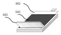
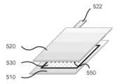
도 2 내지 4는 포지티브 집전체(210) 및 네거티브 집전체(220)를 포함하는 전기화학 전지(200)를 도시한다. 반고체 캐소드(240)는 포지티브 집전체(210) 상에 배치되고 반고체 애노드(250)는 네거티브 집전체(220) 상에 배치된다. 분리기(230)는 반고체 캐소드(240)와 반고체 애노드(250) 사이에 배치된다. 전기화학 전지(200)는 파우치(260) 내에 배치된다.Figures 2 to 4 illustrate an electrochemical cell (200) including a positive current collector (210) and a negative current collector (220). A semi-solid cathode (240) is disposed on the positive current collector (210) and a semi-solid anode (250) is disposed on the negative current collector (220). A separator (230) is disposed between the semi-solid cathode (240) and the semi-solid anode (250). The electrochemical cell (200) is disposed within a pouch (260).
포지티브 집전체(210)는 금속 호일, 예를 들어, 구리 또는 알루미늄 호일, 또는 전기화학 전지(200) 내에 포함된 포지티브 집전체(210)와 관련하여 기술되는 임의의 다른 물질로부터 형성될 수 있다. 포지티브 집전체(210)는 약 20 ㎛ 내지 약 40 ㎛, 예를 들어, 약 25 ㎛, 약 30 ㎛, 또는 약 35 ㎛의 범위 (그들 사이의 모든 범위를 포함함)의 두께를 가질 수 있다. 일부 실시양태에서, 포지티브 집전체(210)는 약 20 ㎛ 미만, 예를 들어, 약 5 ㎛, 6 ㎛, 7 ㎛, 8 ㎛, 9 ㎛, 10 ㎛, 12 ㎛, 14 ㎛, 16 ㎛, 또는 약 18 ㎛ (그들 사이의 모든 범위를 포함함)의 두께를 가질 수 있다. 포지티브 집전체(210)는 포지티브 리드(214)와 결합된 탭(212)을 포함한다. 일부 실시양태에서, 탭(212)은 포지티브 리드(214)와의 결합을 위해 요망되는 길이로 절단될 수 있다. 포지티브 리드는 임의의 적합한 방법, 예를 들어, 초음파 용접, 클램핑, 크림핑, 접착 테이프 등에 의해 탭(212)과 결합될 수 있는 전도 금속 (예를 들어, 구리 또는 알루미늄)의 스트립일 수 있다. 링(216)은 포지티브 리드(214)의 일부분 주위에 감기고, 전기화학 전지(200)가 파우치(260) 내에 배치될 때 파우치(260)의 가장자리에 맞추어 정렬된다. 따라서 파우치(260)가 밀봉될 때, 링(216)은 파우치(260)가 열적으로 밀봉 가능한 것을 보장한다. 링(216)은 절연 물질, 예를 들어, 엄선된 플라스틱, 예컨대 서린(Surlyn), 또는 임의의 다른 적합한 물질로부터 형성될 수 있다.The positive current collector (210) can be formed from a metal foil, for example, copper or aluminum foil, or any other material described with respect to a positive current collector (210) included within an electrochemical cell (200). The positive current collector (210) can have a thickness in the range of from about 20 μm to about 40 μm, for example, about 25 μm, about 30 μm, or about 35 μm, including all ranges therebetween. In some embodiments, the positive current collector (210) can have a thickness less than about 20 μm, for example, about 5 μm, 6 μm, 7 μm, 8 μm, 9 μm, 10 μm, 12 μm, 14 μm, 16 μm, or about 18 μm, including all ranges therebetween. The positive collector (210) includes a tab (212) coupled with a positive lead (214). In some embodiments, the tab (212) can be cut to a desired length for coupling with the positive lead (214). The positive lead can be a strip of conductive metal (e.g., copper or aluminum) that can be coupled to the tab (212) by any suitable method, such as ultrasonic welding, clamping, crimping, adhesive tape, or the like. The ring (216) is wound around a portion of the positive lead (214) and is aligned with an edge of the pouch (260) when the electrochemical cell (200) is placed within the pouch (260). Thus, when the pouch (260) is sealed, the ring (216) ensures that the pouch (260) is thermally sealable. The ring (216) can be formed from an insulating material, such as a selected plastic, such as Surlyn, or any other suitable material.
네거티브 집전체(220)는 금속 호일, 예를 들어, 구리 또는 알루미늄 호일, 또는 전기화학 전지(200) 내에 포함된 네거티브 집전체(220)와 관련하여 기술되는 임의의 다른 물질로부터 형성될 수 있다. 네거티브 집전체(220)는 약 20 ㎛ 내지 약 40 ㎛, 예를 들어, 약 25 ㎛, 약 30 ㎛, 또는 약 35 ㎛의 범위 (그들 사이의 모든 범위를 포함함)의 두께를 가질 수 있다. 일부 실시양태에서, 네거티브 집전체(220)는 약 20 ㎛ 미만, 예를 들어, 약 5 ㎛, 6 ㎛, 7 ㎛, 8 ㎛, 9 ㎛, 10 ㎛, 12 ㎛, 14 ㎛, 16 ㎛, 또는 약 18 ㎛ (그들 사이의 모든 범위를 포함함)의 두께를 가질 수 있다. 네거티브 집전체(220)는 또한 네거티브 리드(224)와 결합된 탭(222)을 포함한다. 일부 실시양태에서, 탭(222)은 네거티브 리드(224)와의 결합을 위해 요망되는 길이로 절단될 수 있다. 네거티브 리드(224)는 포지티브 리드(214)와 상당히 유사할 수 있고, 본원에 추가로 상세하게 기술되어 있지 않다. 링(226)은 네거티브 리드(224)의 일부분 주위에 감기고, 전기화학 전지(200)가 파우치(260) 내에 배치될 때 파우치(260)의 가장자리에 맞추어 정렬된다. 따라서 파우치(260)가 밀봉될 때, 링(226)은 파우치(260)가 열적으로 밀봉 가능한 것을 보장한다. 링(226)은 절연 물질, 예를 들어, 엄선된 플라스틱, 예컨대 서린, 또는 임의의 다른 적합한 물질로부터 형성될 수 있다.The negative current collector (220) can be formed from a metal foil, for example, copper or aluminum foil, or any other material described with respect to a negative current collector (220) included within an electrochemical cell (200). The negative current collector (220) can have a thickness in the range of from about 20 μm to about 40 μm, for example, about 25 μm, about 30 μm, or about 35 μm, including all ranges therebetween. In some embodiments, the negative current collector (220) can have a thickness less than about 20 μm, for example, about 5 μm, 6 μm, 7 μm, 8 μm, 9 μm, 10 μm, 12 μm, 14 μm, 16 μm, or about 18 μm, including all ranges therebetween. The negative current collector (220) also includes a tab (222) coupled with a negative lead (224). In some embodiments, the tab (222) can be cut to a desired length for coupling with the negative lead (224). The negative lead (224) can be substantially similar to the positive lead (214) and is not described in further detail herein. The ring (226) is wound around a portion of the negative lead (224) and is aligned with an edge of the pouch (260) when the electrochemical cell (200) is placed within the pouch (260). Thus, when the pouch (260) is sealed, the ring (226) ensures that the pouch (260) is thermally sealable. The ring (226) can be formed from an insulating material, for example, a selected plastic, such as cerin, or any other suitable material.
분리기(230)는 이온-투과성 멤브레인일 수 있고 전기화학 전지(200) 내에 포함된 분리기(230)와 관련하여 기술되는 임의의 물질로부터 형성될 수 있다. 분리기(230)는 약 10 ㎛ 내지 약 30 ㎛, 예를 들어 약 15 ㎛, 약 20 ㎛, 또는 약 25 ㎛ (그들 사이의 모든 범위를 포함함)의 두께를 가질 수 있다.The separator (230) may be an ion-permeable membrane and may be formed from any of the materials described with respect to the separator (230) included within the electrochemical cell (200). The separator (230) may have a thickness of from about 10 μm to about 30 μm, for example, about 15 μm, about 20 μm, or about 25 μm (including all ranges therebetween).
반고체 캐소드(240)는 분리기(230)에 가까이 있는 포지티브 집전체(210)의 제1 표면 상에 배치, 예를 들어 코팅된다. 분리기(230)에서 멀리 있는 포지티브 집전체(210)의 제2 표면은 코팅되지 않은 채로 있다. 마찬가지로, 반고체 애노드(250)는 분리기(230)에 가까이 있는 네거티브 집전체(220)의 제1 표면 상에 배치, 예를 들어 코팅된다. 분리기(230)에서 멀리 있는 네거티브 집전체(220)의 제2 표면은 코팅되지 않은 채로 있다. 달리 말해서, 반고체 캐소드(240) 및 반고체 애노드(250)는 각각 포지티브 집전체(210) 및 네거티브 집전체(220)의 한쪽 면 상에만 코팅된다. 한쪽 면만 코팅하면, 전기화학 전지(200)를 제조하는 데 요구되는 시간이 감소된다. 이로 인해 반고체 캐소드(240) 및/또는 반고체 애노드(250) 배합물 중에 포함된 전해질의 증발 및/또는 열화 (예를 들어 주위 습기로 인함)가 저감된다. 반고체 캐소드(240) 및 반고체 애노드(250)를 각각 전기화학 전지(100) 내에 포함된 반고체 캐소드(140) 및 반고체 애노드(150)와 관련하여 기술된 바와 같은 임의의 성분 (예를 들어, 활성 물질 및/또는 전도성 물질, 전해질, 첨가제, 겔 중합체 등)을 사용하여 배합할 수 있다. 더욱이, 각각의 반고체 캐소드(240) 및/또는 반고체 애노드(250)는 적어도 약 250 ㎛의 두께를 가질 수 있다. 예를 들어, 반고체 캐소드(240) 및/또는 반고체 애노드(250)는 약 250 ㎛ 내지 약 2,000 ㎛의 범위의 두께를 가질 수 있다.The semi-solid cathode (240) is disposed, for example, coated, on a first surface of the positive current collector (210) that is close to the separator (230). A second surface of the positive current collector (210) that is far from the separator (230) remains uncoated. Similarly, the semi-solid anode (250) is disposed, for example, coated, on a first surface of the negative current collector (220) that is close to the separator (230). A second surface of the negative current collector (220) that is far from the separator (230) remains uncoated. In other words, the semi-solid cathode (240) and the semi-solid anode (250) are coated on only one surface of the positive current collector (210) and the negative current collector (220), respectively. Coating only one surface reduces the time required to fabricate the electrochemical cell (200). This reduces evaporation and/or degradation (e.g., due to ambient moisture) of the electrolyte included in the semi-solid cathode (240) and/or semi-solid anode (250) formulation. The semi-solid cathode (240) and the semi-solid anode (250) may be formulated using any of the components (e.g., active materials and/or conductive materials, electrolytes, additives, gel polymers, etc.) described with respect to the semi-solid cathode (140) and the semi-solid anode (150) included in the electrochemical cell (100), respectively. Furthermore, each of the semi-solid cathode (240) and/or semi-solid anode (250) may have a thickness of at least about 250 μm. For example, the semi-solid cathode (240) and/or the semi-solid anode (250) may have a thickness in the range of about 250 μm to about 2,000 μm.
제조된 전기화학 전지(200)는 전기화학 전지(200) 물질을 환경으로부터 기밀 격리시킬 수 있는 다면형(prismatic) 파우치(260) 내에 진공 밀봉될 수 있다. 따라서, 파우치(260)는 전해질 용매 및/또는 부식성 염과 같은 위험 물질이 주위 환경에 누출되는 것을 회피하는 역할을 할 수 있고, 전지 내로의 물 및/또는 산소의 침투를 방지할 수 있다. 파우치(260)의 다른 기능은, 예를 들어, 내부 층의 압축 포장, 안전성 및 취급을 위한 전압 격리, 및 전기화학 전지(200) 조립체의 기계적 보호를 포함할 수 있다.The manufactured electrochemical cell (200) can be vacuum sealed within a prismatic pouch (260) that can hermetically isolate the electrochemical cell (200) material from the environment. Accordingly, the pouch (260) can serve to prevent leakage of hazardous materials such as electrolyte solvent and/or corrosive salts into the surrounding environment, and prevent penetration of water and/or oxygen into the cell. Other functions of the pouch (260) can include, for example, compression packaging of the inner layer, voltage isolation for safety and handling, and mechanical protection of the electrochemical cell (200) assembly.
전형적인 파우치 물질은 예를 들어, 2층 또는 3층 고체 필름-유사 층으로서 형성된, 접착제에 의해 함께 결합된 라미네이트 (예를 들어, 다층 시트)를 포함할 수 있다. 본원에 사용된 단어 "라미네이트"는 또한 서로 화학적으로 접착되지 않은 물질의 층을 지칭할 수 있다. 예를 들어, 층들은 서로 면적 접촉할 수 있고 다른 결합 방법, 예컨대, 예를 들어, 열 밀봉에 의해 결합될 수 있다. 일부 실시양태에서, 파우치(260)는 폴리프로필렌, 예를 들어, 캐스트 프로필렌으로부터 형성될 수 있다. 일부 실시양태에서, 적어도 플라스틱 물질로 형성된 제1 또는 내부 층 및 전자 전도 물질로 형성된 제2 층을 포함해서 전지의 전기화학적 기능성 요소로서 사용될 수 있는 다층 라미네이트 시트를 포함하는 케이싱 또는 파우치를 갖는 전기화학 전지가 형성될 수 있다. 예를 들어, 일부 실시양태에서, 파우치의 전자 전도 물질 (예를 들어, 금속 호일)은 전지를 위한 집전체로서 사용될 수 있다. 일부 실시양태에서, 금속 호일은 통과(pass-through) 탭으로서 사용될 수 있다. 따라서, 전지 파우치의 다층 또는 라미네이트 시트(들)는 포장 물질로서 작용하는 외에도 전지의 전기화학적 기능성 물질로서 사용될 수 있다. 다층 라미네이트 시트를 포함하는 케이싱 또는 파우치를 갖는 전기화학 전지를 제조하는 시스템, 장치, 및 방법은 2014년 11월 17일에 출원된 발명의 명칭 "Electrochemical Cells and Methods of Manufacturing the Same"의 U.S. 특허 공개 제2015/0171406호 ("'406 공개"라고도 지칭됨)에 기술되어 있고, 상기 공개의 전체 개시 내용은 본원에 참조로 포함된다.A typical pouch material can include, for example, a laminate (e.g., a multilayer sheet) bonded together by an adhesive, formed as a two- or three-layer solid film-like layer. The word "laminate" as used herein can also refer to layers of materials that are not chemically bonded to one another. For example, the layers can be in surface contact with one another and can be bonded by other bonding methods, such as, for example, heat sealing. In some embodiments, the pouch (260) can be formed from polypropylene, for example, cast propylene. In some embodiments, an electrochemical cell can be formed having a casing or pouch comprising a multilayer laminate sheet that can be used as an electrochemically functional element of the cell, including at least a first or inner layer formed of a plastic material and a second layer formed of an electronically conductive material. For example, in some embodiments, the electronically conductive material (e.g., a metal foil) of the pouch can be used as a current collector for the cell. In some embodiments, the metal foil can be used as a pass-through tab. Thus, the multilayer or laminate sheet(s) of the battery pouch can be used as an electrochemically functional material of the battery in addition to acting as a packaging material. Systems, devices, and methods for manufacturing an electrochemical cell having a casing or pouch including a multilayer laminate sheet are described in U.S. Patent Publication No. 2015/0171406, entitled "Electrochemical Cells and Methods of Manufacturing the Same," filed Nov. 17, 2014 (also referred to as the "'406 publication"), the entire disclosure of which is incorporated herein by reference.
복수의 전기화학 전지(200), 또는 본원에 기술된 임의의 다른 전기화학 전지는 전기화학 전지 적층체로서 배치되어, 예를 들어, 전기화학 배터리를 형성할 수 있다. 이제 도 5 내지 7을 참조하자면, 전기화학 전지 적층체(3000)가 그것 내에 배치된 복수의 전기화학 전지를 포함하는 것으로 도시되어 있다. 전기화학 전지 적층체(3000)는 파우치(360), 예를 들어 도 2 내지 4와 관련하여 기술된 파우치(260)와 상당히 유사할 수 있는, 그러므로 본원에 추가로 상세하게 기술되지 않는 진공 밀봉된 파우치 내에 배치될 수 있다.A plurality of electrochemical cells (200), or any other electrochemical cells described herein, may be arranged as an electrochemical cell stack to form, for example, an electrochemical battery. Referring now to FIGS. 5-7 , an electrochemical cell stack (3000) is illustrated including a plurality of electrochemical cells arranged therein. The electrochemical cell stack (3000) may be arranged within a pouch (360), for example a vacuum sealed pouch which may be substantially similar to the pouch (260) described with reference to FIGS. 2-4 and is therefore not described in further detail herein.
전기화학 전지 적층체(3000) 내에 포함된 각각의 복수의 전기화학 전지, 예를 들어 제2 전기화학 전지(300b) (도 6)는 전기화학 전지(100, 또는 200)와 상당히 유사할 수 있다. 복수의 전기화학 전지 내에 포함된 각각의 집전체는 탭을 포함한다. 예를 들어, 도 6에 도시된 바와 같이, 제2 전기화학 전지(300b)의 포지티브 집전체(310b) (도 7)는 탭(312b)을 포함하고, 제2 전기화학 전지(300b)의 네거티브 집전체(320b)는 탭(322b)을 포함한다. 복수의 전기화학 전지 내에 포함된 포지티브 집전체의 각각의 탭은 포지티브 배일(313) 내에서 함께 결합되고, 이어서 이는 포지티브 리드(314)에 결합된다. 일부 실시양태에서, 포지티브 집전체의 각각의 탭은 서로의 위에 굽혀져서 포지티브 배일(313)을 형성할 수 있다. 일부 실시양태에서, 포지티브 배일(313) 내에 포함된 탭은 포지티브 리드(314)와의 결합에 요망되는 길이로 절단될 수 있다. 일부 실시양태에서, 전지의 내부를 향해 배치된 전지(300) 내에 포함된 포지티브 집전체(310) 및/또는 네거티브 집전체(320)는 최외부 전기화학 전지(300) 내에 포함된 포지티브 집전체(310)의 탭(312) 및/또는 네거티브 집전체(320)의 탭(322)보다 훨씬 더 짧은 탭을 가질 수 있다. 예를 들어, 전기화학 전지(300c) 내에 포함된 포지티브 집전체(310c)의 탭은 각각 전기화학 전지(300a 및 300b) 내에 포함된 포지티브 집전체(310a 및 310b)의 탭보다 훨씬 더 길 수 있다. 마찬가지로, 전기화학 전지(300a) 내에 포함된 네거티브 집전체(320a)의 탭은 각각 전기화학 전지(300b 및 300c) 내에 포함된 네거티브 집전체(320b 및 320c)의 탭보다 훨씬 더 길 수 있다. 이러한 실시양태에서, 더 짧은 탭은, 예를 들어, 초음파 용접, 클램핑, 크림핑, 접착 테이프 등을 통해 더 긴 탭에 결합되어 배일 (즉, 배일(313 및 323))을 형성할 수 있다. 이어서 최외부 포지티브 집전체 및 최외부 네거티브 집전체 (예를 들어, 포지티브 집전체(310c) 및 네거티브 집전체(310a))의 더 긴 탭은 포지티브 리드(314) 및 네거티브 리드(324)에 결합될 수 있다. 이러한 방식으로, 탭을 형성하는 데 요구되는 물질의 양이 감소됨으로써, 전기화학 전지(300)의 비용 및/또는 전체 중량이 감소될 수 있다. 일부 실시양태에서, 최내부 전기화학 전지(300)의 포지티브 집전체(310) 및 네거티브 집전체의 탭은 전기화학 전지 적층체(3000) 내에 포함된 나머지 전기화학 전지의 포지티브 집전체(310) 및 네거티브 집전체(320)의 탭(310 및 320)보다 더 길 수 있다. 일부 실시양태에서, 더 긴 탭을 포함하는 포지티브 집전체(310) 및/또는 네거티브 집전체(320)는 전기화학 전지 적층체(3000) 내에 포함된 다른 전기화학 전지(300) 내에 포함된 포지티브 집전체(310) 및/또는 네거티브 집전체(320)보다 훨씬 더 두꺼울 수 있다. 일부 실시양태에서, 각각의 포지티브 집전체(310) 및 네거티브 집전체(320)는 파우치(360)로부터 밖으로 연장될 정도로 충분히 길 수 있는 (예를 들어, 각각 최외부 포지티브 집전체(310) 및 최외부 네거티브 집전체(320)의 포지티브 탭(312) 및 네거티브 탭(322)과 대략 동일한 길이의) 탭을 가질 수 있다. 이러한 실시양태에서, 예를 들어, 각각의 포지티브 집전체(310)의 탭은, 예를 들어, 초음파 용접, 클램핑, 크림핑, 접착 테이프 등을 통해 함께 결합되어 포지티브 배일 (예를 들어, 배일(313))을 형성할 수 있다. 마찬가지로, 각각의 네거티브 집전체(320)의 탭은 본원에 기술된 바와 같이 함께 결합되어 네거티브 배일 (예를 들어, 배일(323))을 형성할 수 있다. 본원에 기술된 바와 같이, 포지티브 배일 (각각의 포지티브 집전체의 탭을 포함함) 및 네거티브 배일 (각각의 네거티브 집전체의 탭을 포함함)은 파우치로부터 밖으로 연장될 수 있고, 전기화학 전지 적층체(3000)를 전기적으로 접속시키는 데 사용될 수 있다. 달리 말해서, 이러한 실시양태에서, 포지티브 리드(314) 및 네거티브 리드(324)가 전기화학 전지 적층체 내에 포함되지 않도록, 전기화학 전지 적층체(3000)는 포지티브 배일 및 네거티브 배일을 통해 외부 전자 성분에 직접 전기적으로 결합될 수 있다.Each of the plurality of electrochemical cells included in the electrochemical cell stack (3000), for example, the second electrochemical cell (300b) ( FIG. 6 ), can be substantially similar to the electrochemical cell (100, or 200). Each of the current collectors included in the plurality of electrochemical cells includes a tab. For example, as illustrated in FIG. 6 , the positive current collector (310b) ( FIG. 7 ) of the second electrochemical cell (300b) includes a tab (312b), and the negative current collector (320b) of the second electrochemical cell (300b) includes a tab (322b). The respective tabs of the positive current collectors included in the plurality of electrochemical cells are joined together within a positive shield (313), which is then joined to a positive lead (314). In some embodiments, the respective tabs of the positive current collectors can be bent over each other to form the positive shield (313). In some embodiments, the tabs included within the positive lead (313) can be cut to a length desired for coupling with the positive lead (314). In some embodiments, the positive current collector (310) and/or the negative current collector (320) included within the cell (300) positioned toward the interior of the cell can have tabs that are much shorter than the tabs (312) of the positive current collector (310) and/or the tabs (322) of the negative current collector (320) included within the outermost electrochemical cell (300). For example, the tabs of the positive current collector (310c) included within the electrochemical cell (300c) can be much longer than the tabs of the positive current collectors (310a and 310b) included within the electrochemical cells (300a and 300b), respectively. Likewise, the tabs of the negative current collector (320a) included in the electrochemical cell (300a) may be much longer than the tabs of the negative current collectors (320b and 320c) included in the electrochemical cells (300b and 300c), respectively. In such embodiments, the shorter tabs may be joined to the longer tabs, for example, via ultrasonic welding, clamping, crimping, adhesive tape, or the like, to form the bails (i.e., the bails (313 and 323)). The longer tabs of the outermost positive current collector and the outermost negative current collector (e.g., the positive current collector (310c) and the negative current collector (310a)) may then be joined to the positive lead (314) and the negative lead (324). In this manner, the amount of material required to form the tabs may be reduced, thereby reducing the cost and/or overall weight of the electrochemical cell (300). In some embodiments, the tabs of the positive current collector (310) and the negative current collector of the innermost electrochemical cell (300) can be longer than the tabs (310 and 320) of the positive current collector (310) and the negative current collector (320) of the other electrochemical cells included within the electrochemical cell stack (3000). In some embodiments, the positive current collector (310) and/or the negative current collector (320) including the longer tabs can be much thicker than the positive current collector (310) and/or the negative current collector (320) included within the other electrochemical cells (300) included within the electrochemical cell stack (3000). In some embodiments, each of the positive current collectors (310) and the negative current collectors (320) can have tabs that are sufficiently long to extend outward from the pouch (360) (e.g., approximately the same length as the positive tabs (312) and the negative tabs (322) of the outermost positive current collectors (310) and the outermost negative current collectors (320), respectively). In such embodiments, for example, the tabs of each of the positive current collectors (310) can be joined together, for example, via ultrasonic welding, clamping, crimping, adhesive tape, or the like, to form a positive bail (e.g., bail (313)). Similarly, the tabs of each of the negative current collectors (320) can be joined together, as described herein, to form a negative bail (e.g., bail (323)). As described herein, the positive bail (comprising a tab from each positive collector) and the negative bail (comprising a tab from each negative collector) can extend outward from the pouch and can be used to electrically connect the electrochemical cell stack (3000). In other words, in such embodiments, the electrochemical cell stack (3000) can be electrically coupled directly to external electronic components through the positive bail and the negative bail, such that the positive lead (314) and the negative lead (324) are not included within the electrochemical cell stack.
포지티브 리드(314)는 임의의 적합한 방법, 예를 들어, 초음파 용접, 클램핑, 크림핑, 접착 테이프 등에 의해 포지티브 배일(313)에 결합될 수 있는 전도 금속 (예를 들어, 구리 또는 알루미늄)의 스트립일 수 있다. 링(316)은 포지티브 리드(314)의 일부분 주위에 감기고 전기화학 전지(300)가 파우치(360) 내에 배치될 때 파우치(360)의 가장자리에 맞추어 정렬된다. 따라서 파우치(360)가 밀봉될 때, 링(316)은 파우치(360)가 열적으로 밀봉 가능한 것을 보장한다. 링(316)은 절연 물질, 예를 들어, 엄선된 플라스틱, 예컨대 서린, 또는 임의의 다른 적합한 물질로부터 형성될 수 있다. 마찬가지로, 복수의 전기화학 전지 내에 포함된 네거티브 집전체의 각각의 탭은 네거티브 배일(323) 내에서 함께 결합하고, 이어서 이는 네거티브 리드(324)에 결합된다. 일부 실시양태에서, 네거티브 집전체의 각각의 탭은 서로의 위에 굽혀져서 네거티브 배일(323)을 형성할 수 있다. 일부 실시양태에서, 네거티브 배일(323) 내에 포함된 탭은 포지티브 리드(314)와의 결합을 위해 요망되는 길이로 절단될 수 있다. 네거티브 리드(324)는 포지티브 리드(314)와 상당히 유사할 수 있고, 그러므로 본원에 추가로 상세하게 기술되지 않는다. 게다가, 링(326)은 네거티브 리드(324)의 일부분 주위에 감기고 전기화학 전지(300)가 파우치(360) 내에 배치될 때 파우치(360)의 가장자리에 맞추어 정렬된다. 링(326)은 링(316)과 상당히 유사할 수 있고, 그러므로 본원에 추가로 상세하게 기술되지 않는다.The positive lead (314) may be a strip of conductive metal (e.g., copper or aluminum) that may be joined to the positive bail (313) by any suitable method, such as ultrasonic welding, clamping, crimping, adhesive tape, or the like. The ring (316) is wound around a portion of the positive lead (314) and is aligned with an edge of the pouch (360) when the electrochemical cell (300) is placed within the pouch (360). Thus, when the pouch (360) is sealed, the ring (316) ensures that the pouch (360) is thermally sealable. The ring (316) may be formed from an insulating material, such as a selected plastic, such as cerin, or any other suitable material. Likewise, each tab of the negative current collectors included within the plurality of electrochemical cells are joined together within the negative bail (323), which is then joined to the negative lead (324). In some embodiments, each tab of the negative current collector can be bent over one another to form a negative bail (323). In some embodiments, the tabs included within the negative bail (323) can be cut to a desired length for mating with the positive lead (314). The negative lead (324) can be substantially similar to the positive lead (314), and therefore is not described in further detail herein. In addition, the ring (326) is wound around a portion of the negative lead (324) and aligned with an edge of the pouch (360) when the electrochemical cell (300) is placed within the pouch (360). The ring (326) can be substantially similar to the ring (316), and therefore is not described in further detail herein.
도 7은 선 AA (도 6)를 따라 취해진 전기화학 전지 적층체(3000)의 일부분의 측단면도를 도시한다. 전기화학 전지 적층체(3000)의 일부분은 제1 전기화학 전지(300a), 제2 전기화학 전지(300b) 및 제3 전기화학 전지(300c)를 포함한다. 제1 전기화학 전지(300a)는 제1 포지티브 집전체(310a), 제1 네거티브 집전체(320a) 및 제1 분리기(330a)를 포함한다. 제1 반고체 캐소드(340a)는 제1 분리기(330a) 쪽을 향하는 제1 포지티브 집전체(310a)의 한쪽 면 상에만 배치된다. 마찬가지로, 제1 반고체 애노드(350a)는 제1 분리기(330a) 쪽을 향하는 제1 네거티브 집전체(320a)의 한쪽 면 상에만 배치된다. 제1 분리기(330a)는 제1 반고체 캐소드(340a)와 제1 반고체 애노드(350a) 사이에 배치된다.FIG. 7 is a cross-sectional side view of a portion of an electrochemical cell stack (3000) taken along line AA (FIG. 6). The portion of the electrochemical cell stack (3000) includes a first electrochemical cell (300a), a second electrochemical cell (300b), and a third electrochemical cell (300c). The first electrochemical cell (300a) includes a first positive current collector (310a), a first negative current collector (320a), and a first separator (330a). A first semi-solid cathode (340a) is disposed only on one side of the first positive current collector (310a) facing the first separator (330a). Similarly, a first semi-solid anode (350a) is disposed only on one side of the first negative current collector (320a) facing the first separator (330a). The first separator (330a) is placed between the first semi-solid cathode (340a) and the first semi-solid anode (350a).
제2 전기화학 전지(300b)는 제2 포지티브 집전체(310b), 제2 네거티브 집전체(320b) 및 제2 분리기(330b)를 포함한다. 제2 반고체 캐소드(340b)는 제2 분리기(330b) 쪽을 향하는 제2 포지티브 집전체(310b)의 한쪽 면 상에만 배치된다. 마찬가지로, 제2 반고체 애노드(350b)는 제2 분리기(330b) 쪽을 향하는 제2 네거티브 집전체(320b)의 한쪽 면 상에만 배치된다. 제2 분리기(330b)는 제2 반고체 캐소드(340b)와 제2 반고체 애노드(350b) 사이에 배치된다.The second electrochemical cell (300b) includes a second positive current collector (310b), a second negative current collector (320b), and a second separator (330b). The second semi-solid cathode (340b) is disposed only on one side of the second positive current collector (310b) facing the second separator (330b). Similarly, the second semi-solid anode (350b) is disposed only on one side of the second negative current collector (320b) facing the second separator (330b). The second separator (330b) is disposed between the second semi-solid cathode (340b) and the second semi-solid anode (350b).
제3 전기화학 전지(300c)는 제3 포지티브 집전체(310c), 제3 네거티브 집전체(320c) 및 제3 분리기(330c)를 포함한다. 제3 반고체 캐소드(340c)는 제3 분리기(330c) 쪽을 향하는 제3 포지티브 집전체(310c)의 한쪽 면 상에만 배치된다. 마찬가지로, 제3 반고체 애노드(350c)는 제3 분리기(330c) 쪽을 향하는 제3 네거티브 집전체(320c)의 한쪽 면 상에만 배치된다. 제3 분리기(330c)는 제3 반고체 캐소드(340c)와 제3 반고체 애노드(350c) 사이에 배치된다.The third electrochemical cell (300c) includes a third positive current collector (310c), a third negative current collector (320c), and a third separator (330c). The third semi-solid cathode (340c) is disposed only on one side of the third positive current collector (310c) facing the third separator (330c). Similarly, the third semi-solid anode (350c) is disposed only on one side of the third negative current collector (320c) facing the third separator (330c). The third separator (330c) is disposed between the third semi-solid cathode (340c) and the third semi-solid anode (350c).
제1 전기화학 전지(300a), 제2 전기화학 전지(300b), 및 제3 전기화학 전지(300c)는 서로 상당히 유사할 수 있다. 전기화학 전지 적층체(3000) 내에 포함된 각각의 전기화학 전지 내에 포함된 포지티브 집전체, 네거티브 집전체, 및 분리기는 전기화학 전지(100) 내에 포함된 포지티브 집전체(110), 네거티브 집전체(120) 및 분리기(130)와 관련하여 기술되는 임의의 물질로부터 형성될 수 있다. 게다가, 전기화학 전지 적층체(3000)의 각각의 전기화학 전지 내에 포함된 반고체 캐소드 및 반고체 애노드는 전기화학 전지(100) 내에 포함된 반고체 캐소드(140) 및 반고체 애노드(150)과 관련하여 기술되는 임의의 물질 또는 방법에 의해 배합될 수 있다.The first electrochemical cell (300a), the second electrochemical cell (300b), and the third electrochemical cell (300c) may be substantially similar to each other. The positive current collector, the negative current collector, and the separator included in each electrochemical cell included in the electrochemical cell stack (3000) may be formed from any of the materials described with respect to the positive current collector (110), the negative current collector (120), and the separator (130) included in the electrochemical cell (100). In addition, the semi-solid cathode and the semi-solid anode included in each electrochemical cell of the electrochemical cell stack (3000) may be formulated by any of the materials or methods described with respect to the semi-solid cathode (140) and the semi-solid anode (150) included in the electrochemical cell (100).
제2 포지티브 집전체(310b)의 코팅되지 않은 면이 제1 포지티브 집전체(310a)의 코팅되지 않은 면에 인접하여 맞닿도록, 제2 전기화학 전지(300b)는 제1 전기화학 전지(300a) 상에 배치된다. 마찬가지로, 제3 네거티브 집전체(320c)의 코팅되지 않은 면이 제1 네거티브 집전체(320a)의 코팅되지 않은 면에 인접하여 맞닿도록, 제3 전기화학 전지(300c)는 제1 전기화학 전지(300a) 상에 배치된다. 전기화학 전지 적층체(3000)가 8개의 전기화학 전지를 포함하는 것으로 도시되어 있지만 (도 6), 임의의 개수의 전기화학 전지가 전기화학 전지 적층체(3000) 내에 포함될 수 있다. 본원에 도시되어 있지는 않지만, 일부 실시양태에서, 이격자, 예를 들어, 전기 및/또는 열 절연 이격자가 각각의 인접한 전기화학 전지들 사이에 배치될 수 있다. 일부 실시양태에서, 이격자는 전기화학 전지 적층체(3000) 내에 포함된 각각의 전기화학 전지 상에 적층체 압력을 가하도록 구성될 수 있다. 적합한 이격자는, 예를 들어, 폼 패드, 고무 패드, 플라스틱 시트, 종이 또는 판지 스트립 등을 포함할 수 있다.The second electrochemical cell (300b) is disposed on the first electrochemical cell (300a) such that the uncoated side of the second positive current collector (310b) is adjacent to and in contact with the uncoated side of the first positive current collector (310a). Similarly, the third electrochemical cell (300c) is disposed on the first electrochemical cell (300a) such that the uncoated side of the third negative current collector (320c) is adjacent to and in contact with the uncoated side of the first negative current collector (320a). Although the electrochemical cell stack (3000) is depicted as including eight electrochemical cells ( FIG. 6 ), any number of electrochemical cells may be included in the electrochemical cell stack (3000). Although not depicted herein, in some embodiments, a spacer, such as an electrically and/or thermally insulating spacer, may be disposed between each adjacent electrochemical cell. In some embodiments, the spacers can be configured to apply stack pressure on each electrochemical cell included within the electrochemical cell stack (3000). Suitable spacers can include, for example, foam pads, rubber pads, plastic sheets, strips of paper or cardboard, and the like.
통상의 전기화학 전지 적층체에 비해, 전기화학 전지 적층체(3000)는 더 짧은 시간 내에 형성될 수 있다. 이로 인해 본원에 기술된 바와 같이 전해질의 증발 및/또는 열화가 최소화될 수 있다. 전기화학 전지 적층체(3000)는, 집전체의 양쪽 면 상에 코팅된 본원에 기술된 반고체 전극을 포함하는 유사한 크기의 전기화학 전지 적층체에 비해, 더 작은 활성 물질 대 불활성 물질 비를 가질 수 있다. 그러나, 집전체의 양쪽 면 상에 코팅된 통상의 전극을 포함하는 통상의 전기화학 전지 적층체에 비해, 전기화학 전지 적층체는 여전히 더 높은 활성 물질 대 불활성 물질 비를 가질 수 있다. 이는, 일반적으로 약 200 ㎛보다 더 두껍게 제조될 수 없는 통상의 전극에 비해, 반고체 전극은 훨씬 더 두껍게, 예를 들어 약 250 ㎛ 내지 약 2,000 ㎛의 범위로 제조될 수 있기 때문이다. 따라서, 필적할 만한 에너지 밀도 및 충전 용량을 제공하는 통상의 전기화학 전지 적층체에 비해, 전기화학 전지 적층체(3000)는 전기화학 전지 적층체(3000) 내에 포함된 더 적은 개수의 전기화학 전지 (예를 들어, 전기화학 전지(300))를 사용하여 요망되는 에너지 밀도 및 충전 용량을 제공할 수 있다. 게다가, 전기화학 전지 적층체(300) 내에 포함된, 단일 면이 코팅된 전기화학 전지(300)는 통상의 전지 내에 포함될 수 없는 안전성 또는 보호성 특징부를 포함할 수 있다. 예를 들어, 안전성 주변부 또는 벽이 반고체 캐소드(230) 및 반고체 애노드(240)를 보호하기 위해 전기화학 전지 적층체(3000) 내에 포함된 집전체 (즉, 포지티브 집전체(310) 및 네거티브 집전체(320))의 가장자리 주위에 배치될 수 있다. 더욱이, 전기화학 전지 적층체(3000) 내에 포함된 인접한 전기화학 전지들 사이의 약간의 정렬불량은 용인될 수 있어서, 전기화학 전지 적층체(3000)는 통상의 전기화학 전지 적층체에 비해 더 짧은 시간 내에 형성될 수 있다.Compared to conventional electrochemical cell stacks, the electrochemical cell stack (3000) can be formed in a shorter time period. This can minimize evaporation and/or degradation of the electrolyte as described herein. The electrochemical cell stack (3000) can have a lower active material to inert material ratio than a similarly sized electrochemical cell stack comprising the semi-solid electrodes described herein coated on both sides of a current collector. However, the electrochemical cell stack can still have a higher active material to inert material ratio than a conventional electrochemical cell stack comprising conventional electrodes coated on both sides of a current collector. This is because, compared to conventional electrodes, which generally cannot be manufactured thicker than about 200 μm, the semi-solid electrodes can be manufactured much thicker, for example, in the range of about 250 μm to about 2,000 μm. Thus, compared to conventional electrochemical cell stacks that provide comparable energy density and charge capacity, the electrochemical cell stack (3000) can provide the desired energy density and charge capacity using a smaller number of electrochemical cells (e.g., the electrochemical cells (300)) included within the electrochemical cell stack (3000). Additionally, the single-sided coated electrochemical cells (300) included within the electrochemical cell stack (300) can include safety or protection features that may not be included in conventional cells. For example, a safety perimeter or wall can be positioned around the edges of current collectors included within the electrochemical cell stack (3000) (i.e., the positive current collector (310) and the negative current collector (320)) to protect the semi-solid cathode (230) and the semi-solid anode (240). Moreover, slight misalignment between adjacent electrochemical cells included in the electrochemical cell stack (3000) can be tolerated, so that the electrochemical cell stack (3000) can be formed in a shorter time period than conventional electrochemical cell stacks.
일부 실시양태에서, 전기화학 전지 적층체는 복수의 포지티브 및 네거티브 집전체를 포함하는 복수의 전지 적층체를 포함할 수 있다. 복수의 포지티브 집전체 중 하나 및 복수의 네거티브 집전체 중 하나는 나머지 집전체의 탭보다 훨씬 더 긴 탭을 가질 수 있고 리드가 요구되지 않도록 외부 전자제품과의 접속을 위해 전기화학 전지 파우치로부터 밖으로 연장될 수 있다. 예를 들어, 이제 도 8을 참조하자면, 전기화학 전지 적층체(4000)는 그것 내에 배치된 복수의 전기화학 전지를 포함하는 것으로 도시되어 있다. 전기화학 전지 적층체(4000)는 파우치 (도시되지 않음), 예를 들어 도 2 내지 4와 관련하여 기술된 파우치(260)와 상당히 유사할 수 있는 진공 밀봉된 파우치 내에 배치될 수 있다.In some embodiments, the electrochemical cell stack can include a plurality of cell stacks comprising a plurality of positive and negative current collectors. One of the plurality of positive current collectors and one of the plurality of negative current collectors can have tabs that are much longer than the tabs of the remaining current collectors and can extend outwardly from the electrochemical cell pouch for connection to external electronics such that no leads are required. For example, referring now to FIG. 8 , an electrochemical cell stack (4000) is illustrated including a plurality of electrochemical cells disposed therein. The electrochemical cell stack (4000) can be disposed within a pouch (not shown), for example, a vacuum-sealed pouch that can be substantially similar to the pouch (260) described with respect to FIGS. 2-4 .
전기화학 전지 적층체(4000) 내에 포함된 각각의 복수의 전기화학 전지는 전기화학 전지(100, 200, 또는 300)와 상당히 유사할 수 있고, 그러므로 본원에 추가로 상세하게 기술되지 않는다. 복수의 전기화학 전지 내에 포함된 각각의 집전체는 탭을 포함한다. 예를 들어, 도 8에 도시된 바와 같이, 최외부 포지티브 집전체(410b)는 나머지 포지티브 집전체의 탭보다 훨씬 더 긴 탭(412b)을 포함할 수 있다. 포지티브 집전체의 탭은 배일(413) 내에서 함께 결합될 수 있고 결합 메커니즘(413), 예컨대, 예를 들어, 초음파 용접, 클램핑, 크림핑, 접착 테이프 등에 의해 서로 결합될 수 있다. 마찬가지로, 최외부 네거티브 집전체(420a)는 나머지 네거티브 집전체의 탭보다 훨씬 더 긴 탭(422a)을 포함할 수 있다. 네거티브 집전체의 탭은 배일(423) 내에서 함께 결합될 수 있고 결합 메커니즘(425), 예컨대, 예를 들어, 초음파 용접, 클램핑, 크림핑, 접착 테이프 등에 의해 서로 결합된다. 이러한 방식으로, 각각 나머지 탭보다 훨씬 더 긴 포지티브 집전체(410b)의 탭(412b) 및 네거티브 집전체(420b)의 탭(422a)이 배일 및 파우치로부터 밖으로 연장되도록, 포지티브 집전체 및 네거티브 집전체의 각각의 탭은 서로 전자적으로 결합된다. 따라서, 포지티브 탭(412b) 및 네거티브 탭(422a)은 임의의 부수적인 성분 (예를 들어, 리드)가 사용되지 않도록 외부 전자제품과의 전자적 접속을 위해 사용될 수 있다.Each of the plurality of electrochemical cells included in the electrochemical cell stack (4000) may be substantially similar to the electrochemical cells (100, 200, or 300), and therefore are not described in further detail herein. Each current collector included in the plurality of electrochemical cells includes tabs. For example, as illustrated in FIG. 8 , the outermost positive current collector (410b) may include tabs (412b) that are much longer than the tabs of the remaining positive current collectors. The tabs of the positive current collectors may be joined together within the bail (413) and joined to one another by a joining mechanism (413), such as, for example, ultrasonic welding, clamping, crimping, adhesive tape, or the like. Similarly, the outermost negative current collector (420a) may include tabs (422a) that are much longer than the tabs of the remaining negative current collectors. The tabs of the negative collectors can be joined together within the bail (423) and joined to each other by a joining mechanism (425), such as, for example, ultrasonic welding, clamping, crimping, adhesive tape, or the like. In this manner, the respective tabs of the positive collector (410b) and the negative collector (420b) are electronically joined to each other such that the tabs (412b) of the positive collector (410b) and the tabs (422a) of the negative collector (420b) extend outward from the bail and pouch, respectively, which are much longer than the remaining tabs. Thus, the positive tabs (412b) and the negative tabs (422a) can be used for electronic connection with external electronics without using any additional components (e.g., leads).
더욱 확장하여, 도 9는 네거티브 집전체의 배일을 포함하는, 도 8에서 화살표 B에 의해 도시된 전기화학 전지 적층체(4000)의 일부분의 측면도를 도시한다. 전기화학 전지 적층체는 8개의 전지 적층체를 포함하고, 각각의 상기 적층체는 포지티브 집전체 및 네거티브 집전체를 포함한다. 도 9에 도시된 바와 같이, 전기화학 전지 적층체(4000)는 8개의 네거티브 집전체(422a-h)를 포함한다. 집전체는 배일(423) 내에서 함께 접합되고 본원에 기술된 바와 같은 결합 메커니즘(425)에 의해 서로 결합된다. 네거티브 집전체(420a)의 네거티브 탭(422a) (도 8)은 나머지 네거티브 집전체의 네거티브 탭(422b-h)보다 훨씬 더 길다. 그러므로, 탭(422a)은 전기화학 전지 적층체(4000)를 포장하는 데 사용된 배일 너머로 파우치로부터 밖으로 연장될 수 있다. 이러한 방식으로, 탭(422a)은 전기화학 전지 적층체(4000)를 외부 전자제품과 접속시키는 데 사용될 수 있어서, 전기화학 전지 적층체(4000) 내에 포함된 각각의 네거티브 집전체는 탭(422a)을 통해 외부 전자제품과 전자적 소통을 한다. 따라서, 외부 결합 성분, 예를 들어, 네거티브 리드는 사용되지 않고, 이로 인해 제조는 더 단순해지고 비용이 감소된다.Further expanded, FIG. 9 depicts a side view of a portion of an electrochemical cell stack (4000) including a negative current collector baffle, as illustrated by arrow B in FIG. 8 . The electrochemical cell stack comprises eight cell stacks, each of which comprises a positive current collector and a negative current collector. As illustrated in FIG. 9 , the electrochemical cell stack (4000) comprises eight negative current collectors (422a-h). The current collectors are bonded together within the baffle (423) and joined to one another by a bonding mechanism (425) as described herein. The negative tab (422a) of the negative current collector (420a) ( FIG. 8 ) is much longer than the negative tabs (422b-h) of the remaining negative current collectors. Therefore, the tab (422a) can extend outward from the pouch beyond the baffle used to package the electrochemical cell stack (4000). In this manner, the tab (422a) can be used to connect the electrochemical cell stack (4000) to external electronics, so that each negative current collector included in the electrochemical cell stack (4000) electronically communicates with external electronics through the tab (422a). Accordingly, external bonding components, such as negative leads, are not used, which makes manufacturing simpler and reduces costs.
도 10은 복수의 전기화학 전지를 포함하는 전기화학 전지 적층체를 제조하기 위한 예시적인 방법(400)을 도시하는 흐름도를 도시한다. 방법(400)은 반고체 캐소드를 포지티브 집전체(402)의 한쪽 면 상에 코팅하는 것을 포함한다. 반고체 캐소드는, 예를 들어, 반고체 캐소드(140, 240), 또는 본원에 기술된 임의의 다른 반고체 캐소드를 포함할 수 있다. 적합한 포지티브 집전체는, 예를 들어, 포지티브 집전체(110, 210), 또는 본원에 기술된 임의의 다른 포지티브 집전체를 포함할 수 있다. 이어서 반고체 애노드를 네거티브 집전체(404)의 한쪽 면 상에만 코팅한다. 반고체 애노드는 본원에 기술된 임의의 반고체 애노드, 예를 들어, 반고체 애노드 (150, 250), 또는 본원에 기술된 임의의 다른 반고체 애노드를 포함할 수 있다. 적합한 네거티브 집전체는, 예를 들어, 네거티브 집전체(120, 220), 또는 본원에 기술된 임의의 다른 네거티브 집전체를 포함할 수 있다. 분리기 (예를 들어, 분리기(130, 230), 또는 본원에 기술된 임의의 다른 분리기)를 반고체 캐소드와 반고체 애노드 사이에 배치하여 제1 전기화학 전지(406)를 형성한다. 제2 전기화학 전지를 제1 전기화학 전지(408)와 상당히 유사한 방식으로 형성한다. 게다가, 제3 전기화학 전지를 제1 전기화학 전지(410)와 상당히 유사한 방식으로 형성한다. 각각의 제1 전기화학 전지, 제2 전기화학 전지, 및 제3 전기화학 전지는 전기화학 전지(100, 200), 또는 본원에 기술된 임의의 다른 전기화학 전지와 상당히 유사할 수 있다.FIG. 10 depicts a flow diagram illustrating an exemplary method (400) for making an electrochemical cell stack comprising a plurality of electrochemical cells. The method (400) includes coating a semi-solid cathode on one side of a positive current collector (402). The semi-solid cathode can include, for example, a semi-solid cathode (140, 240), or any other semi-solid cathode described herein. A suitable positive current collector can include, for example, a positive current collector (110, 210), or any other positive current collector described herein. A semi-solid anode is then coated on only one side of a negative current collector (404). The semi-solid anode can include any semi-solid anode described herein, for example, a semi-solid anode (150, 250), or any other semi-solid anode described herein. A suitable negative current collector can include, for example, the negative current collector (120, 220), or any other negative current collector described herein. A separator (e.g., the separator (130, 230), or any other separator described herein) is disposed between the semi-solid cathode and the semi-solid anode to form a first electrochemical cell (406). A second electrochemical cell is formed in a manner substantially similar to the first electrochemical cell (408). Additionally, a third electrochemical cell is formed in a manner substantially similar to the first electrochemical cell (410). Each of the first electrochemical cell, the second electrochemical cell, and the third electrochemical cell can be substantially similar to the electrochemical cell (100, 200), or any other electrochemical cell described herein.
전기화학 전지 적층체를 형성하기 위해, 제2 전기화학 전지의 포지티브 집전체의 코팅되지 않은 면이 제1 전기화학 전지(412)의 포지티브 집전체의 코팅되지 않은 면 상에 (예를 들어, 인접하게 또는 맞닿게) 배치되도록, 제2 전기화학 전지를 제1 전기화학 전지 상에 배치한다. 이어서, 제3 전기화학 전지의 네거티브 집전체의 코팅되지 않은 면이 제1 전기화학 전지의 네거티브 집전체의 코팅되지 않은 면 상에 배치되도록, 제3 전기화학 전지를 제1 전기화학 전지 상에 (예를 들어, 인접하게 또는 맞닿게) 배치하여, 전기화학 전지 적층체를 형성한다. 전기화학 전지 적층체는 전기화학 전지 적층체(3000) 또는 본원에 기술된 임의의 다른 전기화학 전지 적층체와 상당히 유사할 수 있다. 일부 실시양태에서, 전기화학 전지 적층체를 형성하는 데 요구되는 시간은, 임의의 제1 전기화학 전지, 제2 전기화학 전지 및 제3 전기화학 전지의 반고체 애노드 또는 반고체 캐소드 내에 포함된 전해질의 증발이 상당히 저감되도록, 충분히 짧을 수 있다.To form an electrochemical cell stack, a second electrochemical cell is disposed on the first electrochemical cell such that the uncoated side of the positive current collector of the second electrochemical cell is disposed on (e.g., adjacent to or in contact with) the uncoated side of the positive current collector of the first electrochemical cell (412). A third electrochemical cell is then disposed on (e.g., adjacent to or in contact with) the first electrochemical cell such that the uncoated side of the negative current collector of the third electrochemical cell is disposed on the uncoated side of the negative current collector of the first electrochemical cell, thereby forming an electrochemical cell stack. The electrochemical cell stack can be substantially similar to the electrochemical cell stack (3000) or any other electrochemical cell stack described herein. In some embodiments, the time required to form the electrochemical cell stack can be sufficiently short such that evaporation of the electrolyte contained within the semi-solid anode or semi-solid cathode of any of the first electrochemical cell, the second electrochemical cell and the third electrochemical cell is significantly reduced.
일부 실시양태에서, 방법(400)은 임의로 제1 전기화학 전지의 포지티브 집전체와 제2 전기화학 전지의 포지티브 집전체 사이에 제1 이격자를 배치하고/거나 제3 전기화학 전지의 네거티브 집전체와 제1 전기화학 전지의 네거티브 집전체 사이에 제2 이격자를 배치하는 것을 포함할 수 있다. 이격자는 열 및/또는 전기 절연 물질, 예컨대, 예를 들어, 폼 패드, 고무 패드, 플라스틱 시트, 종이 또는 판지 스트립 등을 포함할 수 있다.In some embodiments, the method (400) can optionally include disposing a first spacer between the positive current collector of the first electrochemical cell and the positive current collector of the second electrochemical cell, and/or disposing a second spacer between the negative current collector of the third electrochemical cell and the negative current collector of the first electrochemical cell. The spacer can include a thermally and/or electrically insulating material, such as, for example, a foam pad, a rubber pad, a plastic sheet, a strip of paper or cardboard, or the like.
도 11a 내지 11i는 한 실시양태에 따른, 집전체의 한쪽 면 상에만 코팅된 반고체 전극을 갖는 전기화학 전지(500)의 제조 공정의 다양한 단계를 도시한다. 도 11a에 도시된 바와 같이, 프레임(562) ("이격자 프레임"이라고도 지칭됨)을 전력 연결 탭(512)을 포함하는 집전체(510) 상에 배치한다. 집전체(510)는, 예를 들어, 홀더(565) (본원에 "집전체 홀더"라고도 지칭됨) 상에 놓일 수 있고, 상기 홀더는 집전체(510)를 제자리에 고정하기 위해 홀더(565) 표면에 걸쳐 복수의 작은 구멍 (도시되지 않음)을 통해 임의로 진공을 가할 수 있다. 프레임(562)은 집전체(510)의 위에 놓일 때 아래에 있는 집전체(510)를 노출시킬 수 있는 개구(575)를 갖는다.FIGS. 11A-11I illustrate various steps in a process for fabricating an electrochemical cell (500) having a semi-solid electrode coated on only one side of a current collector, according to one embodiment. As illustrated in FIG. 11A , a frame (562) (also referred to herein as a “spacer frame”) is placed over a current collector (510) including power connection tabs (512). The current collector (510) may be placed, for example, on a holder (565) (also referred to herein as a “current collector holder”), the holder optionally having a vacuum applied thereto through a plurality of small holes (not shown) across a surface of the holder (565) to secure the current collector (510) in place. The frame (562) has openings (575) that, when placed over the current collector (510), expose the underlying current collector (510).
도 11b는 프레임(562)의 개구(575)에 의해 한정된 집전체(510)의 노출된 부분 상에 배치된 전극 슬러리(540)를 도시한다. 개구(575)는 완성된 전극(540)의 표면적을 한정하고 프레임(562)의 두께는 완성된 전극(540)의 두께를 한정한다. 도 11c 및 11d는 집전체(510)의 노출된 부분의 표면을 따라 매끄럽게 되거나 펴 발라진 전극 슬러리(540)를 도시한다. 일부 실시양태에서, 블레이드(580) (본원에 "닥터 블레이드"라고도 지칭됨) 또는 직선형 날을 갖는 기기가 전극 슬러리(540)를 펴 바르는 데 사용될 수 있다. 일부 실시양태에서, 전극 슬러리(540)를 침착시키거나 펴 바르는 동안에 블레이드(580) 또는 홀더(565)를 진동시키기 위해 블레이드(580) 및/또는 홀더(565)를 진동원 (도시되지 않음)에 조작 가능하게 결합시킬 수 있다. 진동은 슬러리 침착 단계 동안 또는 후에 반고체 전극 물질(540)의 분산을 용이하게 할 수 있다.FIG. 11b illustrates electrode slurry (540) disposed on an exposed portion of a current collector (510) defined by an opening (575) of a frame (562). The opening (575) defines the surface area of the finished electrode (540) and the thickness of the frame (562) defines the thickness of the finished electrode (540). FIGS. 11c and 11d illustrate electrode slurry (540) smoothed or spread along the surface of the exposed portion of the current collector (510). In some embodiments, a blade (580) (also referred to herein as a “doctor blade”) or a device having a straight edge may be used to spread the electrode slurry (540). In some embodiments, the blade (580) and/or holder (565) can be operably coupled to a vibration source (not shown) to vibrate the blade (580) or holder (565) while depositing or spreading the electrode slurry (540). The vibration can facilitate dispersion of the semi-solid electrode material (540) during or after the slurry deposition step.
임의로, 기기 (도시되지 않음), 예컨대, 예를 들어, 광학적 또는 레이저 간섭법, 타원계측법 또는 광학적 또는 레이저 스캐닝 탐침을 포함하는 임의의 비-접촉식 측정 기술을 사용하는 광학적 또는 임의의 분석적 도구를 사용하여, 펴 발라진 전극 슬러리(540)의 표면 모폴로지를 검사하고 임의로 표면 균일도 (예를 들어, 두께)를 측정한다. 블레이드(580)가 전극 슬러리(540)를 펴 바르는 동안에 비-접촉식 기기를 현장에서 알맞게 사용할 수 있다.Optionally, the surface morphology of the spread electrode slurry (540) is examined and optionally the surface uniformity (e.g., thickness) is measured using any non-contact measurement technique, including, for example, optical or laser interferometry, ellipsometry or an optical or laser scanning probe, using an optical or any analytical tool (not shown). The non-contact device may be conveniently used in the field while the blade (580) spreads the electrode slurry (540).
도 11e에 도시된 바와 같이, 전극 슬러리(540)를 펴 바른 후에, 프레임(562)을 제거하여, 집전체(510)의 노출된 부분 상에 펴 발라진 전극(540)의 부분만을 남겨 놓을 수 있다. 도 11f에 도시된 바와 같이, 분리기(530)가 전극(540)을 덮도록 분리기(530)를 전극(540) 상에 놓을 수 있다.As illustrated in FIG. 11e, after spreading the electrode slurry (540), the frame (562) can be removed, leaving only the portion of the electrode (540) spread on the exposed portion of the current collector (510). As illustrated in FIG. 11f, the separator (530) can be placed on the electrode (540) so that the separator (530) covers the electrode (540).
상기 도 11a 내지 11f에 도시된 제조 단계는 전극을 집전체 상에 침착시키는 단계를 망라한다. 예를 들어, 전극(540)은 캐소드일 수 있고 집전체(510)는 포지티브 집전체일 수 있다. 반고체 애노드(550)를 네거티브 집전체(520) 상에 배치하기 위해 도 11a 내지 11e에 도시된 제조 단계를 반복할 수 있다. 그러나, 단일 분리기(530)를 전기화학 전지(500)에서 사용하기 때문에, 도 11f에 도시된 제조 단계를 반고체 캐소드 침착 단계 또는 반고체 애노드 침착 단계 중 하나에서만 수행한다.The fabrication steps illustrated in FIGS. 11A to 11F encompass the steps of depositing an electrode on a current collector. For example, the electrode (540) can be a cathode and the current collector (510) can be a positive current collector. The fabrication steps illustrated in FIGS. 11A to 11E can be repeated to place a semi-solid anode (550) on a negative current collector (520). However, since a single separator (530) is used in the electrochemical cell (500), the fabrication steps illustrated in FIG. 11F are performed in only one of the semi-solid cathode deposition step or the semi-solid anode deposition step.
도 11g에 도시된 바와 같이, 반고체 캐소드(540) 및 반고체 애노드(550) 둘 다를 그것의 각각의 집전체(510 및 520) 상에 배치한 후에, 도시된 바와 같이 반고체 캐소드(540) 및 반고체 애노드(550)가 서로를 향하면서 서로의 위에 있고 분리기(530)에 의해서만 분리되도록, 그것들을 정렬할 수 있다. 도시된 바와 같이, 반고체 애노드(550)는 네거티브 집전체(520)의 아랫면 상에 있기 때문에 보이지 않는다. 조립된 전극-적층체는 도 3에 도시된 도해와 비슷하다.As illustrated in FIG. 11g, after both the semi-solid cathode (540) and the semi-solid anode (550) are placed on their respective current collectors (510 and 520), they can be aligned so that the semi-solid cathode (540) and the semi-solid anode (550) are facing each other and are above each other and separated only by the separator (530), as illustrated. As illustrated, the semi-solid anode (550) is not visible because it is on the underside of the negative current collector (520). The assembled electrode-stack is similar to the schematic illustrated in FIG. 3.
도 11h에 가장 잘 도시된 바와 같이, 전기화학 전지(500)는, 이후에 도 11i에 도시된 바와 같은 완성된 전기화학 전지(500)를 형성하도록 진공(566) 및 열(567) 밀봉되는 파우치(560) 내부에 배치된 캐소드-분리기-애노드의 단일 적층체를 포함한다. 포지티브 집전체(510)는 전력 연결 탭(512)을 포함하는 반면에, 네거티브 집전체(520)는 전력 연결 탭(522)을 포함한다. 파우치(560) 내의 완성된 전기화학 전지(500)는 도 2에 도시된 전기화학 전지(200)와 상당히 유사할 수 있다. 일부 실시양태에서, 복수의 전기화학 전지(500)는 적층되어, 도 5 내지 7에 도시된 전기화학 전지 적층체(3000)와 상당히 유사할 수 있는 전기화학 전지 적층체를 형성할 수 있다.As best illustrated in FIG. 11h, the electrochemical cell (500) comprises a single stack of cathode-separator-anode disposed within a pouch (560) that is then vacuum (566) and heat (567) sealed to form a completed electrochemical cell (500) as illustrated in FIG. 11i. The positive current collector (510) comprises a power connection tab (512), while the negative current collector (520) comprises a power connection tab (522). The completed electrochemical cell (500) within the pouch (560) can be substantially similar to the electrochemical cell (200) illustrated in FIG. 2. In some embodiments, a plurality of electrochemical cells (500) can be stacked to form an electrochemical cell stack, which can be substantially similar to the electrochemical cell stack (3000) illustrated in FIGS. 5-7.
시스템, 방법 및 장치의 다양한 실시양태가 상기에 기술되었지만, 그것은 예로서 제시된 것일 뿐이지 제한하려는 것은 아니라는 것을 이해해야 한다. 상기에 기술된 방법 및 단계가 특정한 순서로 일어나는 특정한 일들을 나타내는 경우에, 본 개시 내용의 이익을 취하는 관련 기술분야의 통상의 기술자라면 특정한 단계의 순서는 변경될 수 있고 이러한 변경은 본 발명의 변형에 따른 것이라는 것을 알 것이다. 추가적으로, 가능한 경우에 특정한 단계를 병렬식 공정으로 동시에 수행할 수 있을 뿐만 아니라 상기에 기술된 바와 같이 순차적으로 수행할 수 있다. 실시양태가 특히 도시되고 기술되었지만, 형태 및 세부 사항에 있어서의 다양한 변화가 이루어질 수 있다는 것을 이해할 것이다.While various embodiments of systems, methods, and devices have been described above, it should be understood that they have been presented by way of example only and not limitation. While the methods and steps described above represent particular things that occur in a particular order, those skilled in the art, having the benefit of this disclosure, will recognize that the order of the particular steps may be varied and that such variations constitute variations of the invention. Additionally, where possible, particular steps may be performed simultaneously in a parallel process, as well as sequentially as described above. While embodiments have been particularly illustrated and described, it will be appreciated that various changes in form and detail may be made.
예를 들어, 다양한 실시양태가 특정한 특징부 및/또는 성분의 조합을 갖는 것으로 기술되었지만, 본원에 기술된 임의의 실시양태로부터의 임의의 특징부 및/또는 성분의 임의의 조합 또는 부-조합을 갖는 다른 실시양태가 가능하다. 예를 들어, 전기화학 전지의 일부 실시양태가 다면형인 것으로 기술되었지만, 다른 실시양태에서, 전기화학 전지는 곡선형이거나, 구부러지거나, 파형이거나, 임의의 다른 모양을 가질 수 있다. 또한, 다양한 성분들의 구체적인 구성은 또한 다양할 수 있다. 예를 들어, 다양한 성분의 크기 및 구체적인 모양은 도시된 실시양태와 상이할 수 있으면서도 여전히 본원에 기술된 바와 같은 기능을 제공할 수 있다.For example, while various embodiments are described as having particular combinations of features and/or components, other embodiments are possible having any combination or sub-combination of any of the features and/or components from any of the embodiments described herein. For example, while some embodiments of the electrochemical cell are described as being polyhedral, in other embodiments, the electrochemical cell may be curved, bent, corrugated, or have any other shape. Additionally, the specific configurations of the various components may also vary. For example, the sizes and specific shapes of the various components may differ from the embodiments depicted and still provide functionality as described herein.
Claims (24)
Translated fromKorean제1 표면, 제2 표면, 및 제1 집전체로부터 연장되는 제1 탭을 갖는 상기 제1 집전체 - 상기 제1 집전체의 상기 제1 표면 상에 반고체 캐소드 물질이 배치됨 -; 및
제1 표면, 제2 표면, 및 제2 집전체로부터 연장되는 제2 탭을 갖는 상기 제2 집전체 - 상기 제2 집전체의 상기 제1 표면 상에 상기 반고체 캐소드 물질이 배치됨 -
를 포함하고,
상기 제1 탭 및 상기 제2 탭은 포지티브 배일에서 함께 결합되고, 상기 포지티브 배일은 포지티브 리드에 결합되도록 구성되는, 전기화학 전지 적층체.As an electrochemical cell laminate,
a first current collector having a first surface, a second surface, and a first tab extending from the first current collector, wherein a semi-solid cathode material is disposed on the first surface of the first current collector; and
A second current collector having a first surface, a second surface, and a second tab extending from a second current collector, wherein the semi-solid cathode material is disposed on the first surface of the second current collector.
Including,
An electrochemical cell stack, wherein the first tab and the second tab are coupled together at a positive batten, and the positive batten is configured to be coupled to a positive lead.
상기 제1 집전체의 상기 제2 표면은 코팅되지 않고, 상기 제2 집전체의 상기 제2 표면은 코팅되지 않고, 상기 제1 집전체의 상기 제2 표면에 결합되는, 전기화학 전지 적층체.In the first paragraph,
An electrochemical cell stack, wherein the second surface of the first current collector is uncoated, the second surface of the second current collector is uncoated, and the second surface of the second current collector is bonded to the second surface of the first current collector.
상기 제1 집전체의 상기 제2 표면과 상기 제2 집전체의 상기 제2 표면 사이에 배치된 이격자 - 상기 제2 집전체의 상기 제2 표면은 상기 이격자를 통해 상기 제1 집전체의 상기 제2 표면에 결합됨 -를 더 포함하는, 전기화학 전지 적층체.In the second paragraph,
An electrochemical cell stack further comprising a spacer disposed between the second surface of the first current collector and the second surface of the second current collector, wherein the second surface of the second current collector is bonded to the second surface of the first current collector through the spacer.
제1 표면 및 제2 표면을 갖는 제3 집전체를 추가로 포함하고, 상기 제3 집전체의 상기 제1 표면 상에 반고체 애노드가 배치되고, 상기 제3 집전체의 상기 제2 표면은 코팅되지 않은, 전기화학 전지 적층체.In the first paragraph,
An electrochemical cell stack further comprising a third collector having a first surface and a second surface, wherein a semi-solid anode is disposed on the first surface of the third collector, and the second surface of the third collector is uncoated.
상기 제3 집전체의 상기 반고체 애노드와 상기 제1 집전체의 상기 반고체 캐소드 사이에 배치된 제1 분리기를 추가로 포함하는, 전기화학 전지 적층체.In paragraph 4,
An electrochemical cell stack further comprising a first separator disposed between the semi-solid anode of the third current collector and the semi-solid cathode of the first current collector.
제1 표면 및 제2 표면을 갖는 제4 집전체를 추가로 포함하고, 상기 제4 집전체의 상기 제1 표면 상에 반고체 애노드가 배치되고, 상기 제4 집전체의 상기 제2 표면은 코팅되지 않고, 상기 제3 집전체의 상기 제2 표면에 결합되는, 전기화학 전지 적층체.In paragraph 5,
An electrochemical cell stack further comprising a fourth current collector having a first surface and a second surface, wherein a semi-solid anode is disposed on the first surface of the fourth current collector, and the second surface of the fourth current collector is uncoated and bonded to the second surface of the third current collector.
제3 탭이 상기 제3 집전체로부터 연장되고, 제4 탭이 상기 제4 집전체로부터 연장되고, 상기 제3 탭 및 상기 제4 탭은 네거티브 배일에서 함께 결합되고, 상기 네거티브 배일은 네거티브 리드에 결합되도록 구성되는, 전기화학 전지 적층체.In Article 6,
An electrochemical cell stack, wherein a third tab extends from the third current collector, a fourth tab extends from the fourth current collector, the third tab and the fourth tab are coupled together at a negative batten, and the negative batten is configured to be coupled to a negative lead.
제1 표면 및 제2 표면을 갖는 제5 집전체를 추가로 포함하고, 상기 제5 집전체의 상기 제1 표면 상에 반고체 캐소드가 배치되고, 상기 제5 집전체의 상기 제2 표면은 코팅되지 않는, 전기화학 전지 적층체.In Article 6,
An electrochemical cell stack further comprising a fifth current collector having a first surface and a second surface, wherein a semi-solid cathode is disposed on the first surface of the fifth current collector, and the second surface of the fifth current collector is uncoated.
상기 제4 집전체의 상기 반고체 애노드와 상기 제5 집전체의 상기 반고체 캐소드 사이에 배치된 제2 분리기를 추가로 포함하는, 전기화학 전지 적층체.In Article 8,
An electrochemical cell stack further comprising a second separator disposed between the semi-solid anode of the fourth current collector and the semi-solid cathode of the fifth current collector.
상기 제5 집전체로부터 제5 탭이 연장되고, 상기 제5 탭은 상기 포지티브 배일에 결합되는, 전기화학 전지 적층체.In Article 8,
An electrochemical cell stack, wherein a fifth tab extends from the fifth collector, and the fifth tab is coupled to the positive electrode.
상기 제5 탭은 상기 제1 탭 및 상기 제2 탭의 길이보다 긴 길이를 갖는, 전기화학 전지 적층체.In Article 10,
An electrochemical cell stack, wherein the fifth tab has a length longer than the lengths of the first tab and the second tab.
상기 제5 탭은 상기 제1 탭 및 상기 제2 탭의 두께보다 큰 두께를 갖는, 전기화학 전지 적층체.In Article 11,
An electrochemical cell stack, wherein the fifth tab has a thickness greater than that of the first tab and the second tab.
제1 표면, 제2 표면, 및 제1 집전체로부터 연장되는 제1 탭을 갖는 상기 제1 집전체 - 상기 제1 집전체의 상기 제1 표면 상에 반고체 애노드 물질이 배치됨 -; 및
제1 표면, 제2 표면, 및 제2 집전체로부터 연장되는 제2 탭을 갖는 상기 제2 집전체 - 상기 제2 집전체의 상기 제1 표면 상에 상기 반고체 애노드 물질이 배치됨 -
를 포함하고,
상기 제1 탭 및 상기 제2 탭은 네거티브 배일에서 함께 결합되고, 상기 네거티브 배일은 네거티브 리드에 결합되도록 구성되는, 전기화학 전지 적층체.As an electrochemical cell laminate,
a first current collector having a first surface, a second surface, and a first tab extending from the first current collector, wherein a semi-solid anode material is disposed on the first surface of the first current collector; and
a second current collector having a first surface, a second surface, and a second tab extending from the second current collector, wherein the semi-solid anode material is disposed on the first surface of the second current collector;
Including,
An electrochemical cell stack, wherein the first tab and the second tab are coupled together at a negative bay, and the negative bay is configured to be coupled to a negative lead.
상기 제1 집전체의 상기 제2 표면은 코팅되지 않고, 상기 제2 집전체의 상기 제2 표면은 코팅되지 않고, 상기 제1 집전체의 상기 제2 표면에 결합되는, 전기화학 전지 적층체.In Article 13,
An electrochemical cell stack, wherein the second surface of the first current collector is uncoated, the second surface of the second current collector is uncoated, and the second surface of the second current collector is bonded to the second surface of the first current collector.
상기 제1 집전체의 상기 제2 표면과 상기 제2 집전체의 상기 제2 표면 사이에 배치된 이격자를 추가로 포함하고, 상기 제2 집전체의 상기 제2 표면은 상기 이격자를 통해 상기 제1 집전체의 상기 제2 표면에 결합되는, 전기화학 전지 적층체.In Article 14,
An electrochemical cell stack further comprising a spacer disposed between the second surface of the first current collector and the second surface of the second current collector, wherein the second surface of the second current collector is bonded to the second surface of the first current collector through the spacer.
제1 표면 및 제2 표면을 갖는 제3 집전체를 추가로 포함하고, 상기 제3 집전체의 상기 제1 표면 상에 반고체 캐소드가 배치되고, 상기 제3 집전체의 상기 제2 표면은 코팅되지 않은, 전기화학 전지 적층체.In Article 13,
An electrochemical cell stack further comprising a third current collector having a first surface and a second surface, wherein a semi-solid cathode is disposed on the first surface of the third current collector, and the second surface of the third current collector is uncoated.
상기 제3 집전체의 상기 반고체 캐소드와 상기 제1 집전체의 상기 반고체 애노드 사이에 배치된 제1 분리기를 추가로 포함하는, 전기화학 전지 적층체.In Article 16,
An electrochemical cell stack further comprising a first separator disposed between the semi-solid cathode of the third current collector and the semi-solid anode of the first current collector.
제1 표면 및 제2 표면을 갖는 제4 집전체를 추가로 포함하고, 상기 제4 집전체의 상기 제1 표면 상에 반고체 캐소드가 배치되고, 상기 제4 집전체의 상기 제2 표면은 코팅되지 않고, 상기 제3 집전체의 상기 제2 표면에 결합되는, 전기화학 전지 적층체.In Article 17,
An electrochemical cell stack further comprising a fourth current collector having a first surface and a second surface, wherein a semi-solid cathode is disposed on the first surface of the fourth current collector, and the second surface of the fourth current collector is uncoated and bonded to the second surface of the third current collector.
제3 탭이 상기 제3 집전체로부터 연장되고, 제4 탭이 상기 제4 집전체로부터 연장되고, 상기 제3 탭 및 상기 제4 탭은 포지티브 배일에서 함께 결합되고, 상기 포지티브 배일은 포지티브 리드에 결합되도록 구성되는, 전기화학 전지 적층체.In Article 18,
An electrochemical cell stack, wherein a third tab extends from the third current collector, a fourth tab extends from the fourth current collector, the third tab and the fourth tab are coupled together at a positive terminal, and the positive terminal is configured to be coupled to a positive lead.
제1 표면 및 제2 표면을 갖는 제5 집전체를 추가로 포함하고, 상기 제5 집전체의 상기 제1 표면 상에 반고체 애노드가 배치되고, 상기 제5 집전체의 상기 제2 표면은 코팅되지 않는, 전기화학 전지 적층체.In Article 18,
An electrochemical cell stack further comprising a fifth collector having a first surface and a second surface, wherein a semi-solid anode is disposed on the first surface of the fifth collector, and the second surface of the fifth collector is uncoated.
상기 제4 집전체의 상기 반고체 캐소드와 상기 제5 집전체의 상기 반고체 애노드 사이에 배치된 제2 분리기를 추가로 포함하는, 전기화학 전지 적층체.In Article 20,
An electrochemical cell stack further comprising a second separator disposed between the semi-solid cathode of the fourth current collector and the semi-solid anode of the fifth current collector.
상기 제5 집전체로부터 제5 탭이 연장되고, 상기 제5 탭은 상기 네거티브 배일에 결합되는, 전기화학 전지 적층체.In Article 20,
An electrochemical cell stack, wherein a fifth tab extends from the fifth collector, and the fifth tab is coupled to the negative electrode.
상기 제5 탭은 상기 제1 탭 및 상기 제2 탭의 길이보다 긴 길이를 갖는, 전기화학 전지 적층체.In Article 22,
An electrochemical cell stack, wherein the fifth tab has a length longer than the lengths of the first tab and the second tab.
상기 제5 탭은 상기 제1 탭 및 상기 제2 탭의 두께보다 큰 두께를 갖는, 전기화학 전지 적층체.In Article 23,
An electrochemical cell stack, wherein the fifth tab has a thickness greater than that of the first tab and the second tab.
Priority Applications (1)
| Application Number | Priority Date | Filing Date | Title |
|---|---|---|---|
| KR1020257011095AKR20250052476A (en) | 2014-11-05 | 2015-11-04 | Electrochemical cells having semi-solid electrodes and methods of manufacturing the same |
Applications Claiming Priority (4)
| Application Number | Priority Date | Filing Date | Title |
|---|---|---|---|
| US201462075373P | 2014-11-05 | 2014-11-05 | |
| US62/075,373 | 2014-11-05 | ||
| PCT/US2015/058992WO2016073575A1 (en) | 2014-11-05 | 2015-11-04 | Electrochemical cells having semi-solid electrodes and methods of manufacturing the same |
| KR1020177015132AKR102611365B1 (en) | 2014-11-05 | 2015-11-04 | Electrochemical cells having semi-solid electrodes and methods of manufacturing the same |
Related Parent Applications (1)
| Application Number | Title | Priority Date | Filing Date |
|---|---|---|---|
| KR1020177015132ADivisionKR102611365B1 (en) | 2014-11-05 | 2015-11-04 | Electrochemical cells having semi-solid electrodes and methods of manufacturing the same |
Related Child Applications (1)
| Application Number | Title | Priority Date | Filing Date |
|---|---|---|---|
| KR1020257011095ADivisionKR20250052476A (en) | 2014-11-05 | 2015-11-04 | Electrochemical cells having semi-solid electrodes and methods of manufacturing the same |
Publications (2)
| Publication Number | Publication Date |
|---|---|
| KR20230171477A KR20230171477A (en) | 2023-12-20 |
| KR102793671B1true KR102793671B1 (en) | 2025-04-10 |
Family
ID=54540262
Family Applications (3)
| Application Number | Title | Priority Date | Filing Date |
|---|---|---|---|
| KR1020237041858AActiveKR102793671B1 (en) | 2014-11-05 | 2015-11-04 | Electrochemical cells having semi-solid electrodes and methods of manufacturing the same |
| KR1020257011095APendingKR20250052476A (en) | 2014-11-05 | 2015-11-04 | Electrochemical cells having semi-solid electrodes and methods of manufacturing the same |
| KR1020177015132AActiveKR102611365B1 (en) | 2014-11-05 | 2015-11-04 | Electrochemical cells having semi-solid electrodes and methods of manufacturing the same |
Family Applications After (2)
| Application Number | Title | Priority Date | Filing Date |
|---|---|---|---|
| KR1020257011095APendingKR20250052476A (en) | 2014-11-05 | 2015-11-04 | Electrochemical cells having semi-solid electrodes and methods of manufacturing the same |
| KR1020177015132AActiveKR102611365B1 (en) | 2014-11-05 | 2015-11-04 | Electrochemical cells having semi-solid electrodes and methods of manufacturing the same |
Country Status (9)
| Country | Link |
|---|---|
| US (4) | US10637038B2 (en) |
| EP (3) | EP3216067B1 (en) |
| JP (3) | JP2017533548A (en) |
| KR (3) | KR102793671B1 (en) |
| CN (2) | CN107112444B (en) |
| CA (1) | CA2962788C (en) |
| MY (1) | MY180711A (en) |
| PH (1) | PH12017500654A1 (en) |
| WO (1) | WO2016073575A1 (en) |
Families Citing this family (62)
| Publication number | Priority date | Publication date | Assignee | Title |
|---|---|---|---|---|
| US8722226B2 (en) | 2008-06-12 | 2014-05-13 | 24M Technologies, Inc. | High energy density redox flow device |
| US11909077B2 (en) | 2008-06-12 | 2024-02-20 | Massachusetts Institute Of Technology | High energy density redox flow device |
| EP2754194B1 (en) | 2011-09-07 | 2018-12-12 | 24M Technologies, Inc. | Semi-solid electrode cell having a porous current collector and methods of manufacture |
| US9401501B2 (en) | 2012-05-18 | 2016-07-26 | 24M Technologies, Inc. | Electrochemical cells and methods of manufacturing the same |
| US9484569B2 (en) | 2012-06-13 | 2016-11-01 | 24M Technologies, Inc. | Electrochemical slurry compositions and methods for preparing the same |
| US9362583B2 (en) | 2012-12-13 | 2016-06-07 | 24M Technologies, Inc. | Semi-solid electrodes having high rate capability |
| EP3694032B1 (en) | 2013-03-15 | 2023-01-11 | 24M Technologies, Inc. | Asymmetric battery having a semi-solid cathode and high energy density anode |
| WO2015009990A2 (en) | 2013-07-19 | 2015-01-22 | 24M Technologies, Inc. | Semi-solid electrodes with polymer additive |
| US10230128B2 (en) | 2014-04-09 | 2019-03-12 | 24M Technologies, Inc. | Damage tolerant batteries |
| JP2016076475A (en)* | 2014-08-06 | 2016-05-12 | 株式会社半導体エネルギー研究所 | Electronic device and eyeglass-type device having secondary battery |
| KR102860367B1 (en) | 2014-09-19 | 2025-09-16 | 가부시키가이샤 한도오따이 에네루기 켄큐쇼 | Secondary battery |
| ES2975858T3 (en) | 2014-10-13 | 2024-07-16 | 24M Tech Inc | Systems and methods of charging and forming batteries in series |
| JP7111468B2 (en) | 2014-11-03 | 2022-08-02 | 24エム・テクノロジーズ・インコーポレイテッド | Prelithiation of electrode materials in semi-solid electrodes |
| KR102793671B1 (en) | 2014-11-05 | 2025-04-10 | 24엠 테크놀로지즈, 인크. | Electrochemical cells having semi-solid electrodes and methods of manufacturing the same |
| US10115970B2 (en) | 2015-04-14 | 2018-10-30 | 24M Technologies, Inc. | Semi-solid electrodes with porous current collectors and methods of manufacture |
| US10593952B2 (en) | 2015-05-19 | 2020-03-17 | 24M Technologies Inc. | Mechanical systems and methods for providing edge support and protection in semi-solid electrodes |
| WO2016205663A1 (en) | 2015-06-18 | 2016-12-22 | 24M Technologies, Inc. | Single pouch battery cells and methods of manufacture |
| CN108140851B (en) | 2015-06-19 | 2021-09-28 | 24M技术公司 | Electrochemical cell repair method |
| WO2017124098A1 (en)* | 2016-01-15 | 2017-07-20 | 24M Technologies, Inc. | Systems and methods for infusion mixing a slurry-based electrode |
| CN205376656U (en)* | 2016-01-20 | 2016-07-06 | 宁德新能源科技有限公司 | Secondary battery |
| EP3501049A4 (en)* | 2016-07-22 | 2020-06-03 | Hydro-Québec | Flexible electrode-separator elements, and method for manufacturing same |
| EP3577704A4 (en) | 2017-02-01 | 2021-03-10 | 24m Technologies, Inc. | SYSTEMS AND METHODS FOR IMPROVING SAFETY FEATURES IN ELECTROCHEMICAL CELLS |
| WO2018183828A1 (en) | 2017-03-31 | 2018-10-04 | 24M Technologies, Inc. | Overcharge protection of batteries using current interrupt devices |
| US11476551B2 (en) | 2017-07-31 | 2022-10-18 | 24M Technologies, Inc. | Current interrupt devices using shape memory materials |
| US10854869B2 (en) | 2017-08-17 | 2020-12-01 | 24M Technologies, Inc. | Short-circuit protection of battery cells using fuses |
| JP7029921B2 (en)* | 2017-10-10 | 2022-03-04 | 日産自動車株式会社 | Electrodes for non-aqueous electrolyte secondary batteries |
| DE102017218158A1 (en) | 2017-10-11 | 2019-04-11 | Robert Bosch Gmbh | Method for producing an electrode and galvanic element comprising an electrode |
| WO2019087956A1 (en)* | 2017-10-30 | 2019-05-09 | 京セラ株式会社 | Electrochemical cell and electrochemical cell stack |
| US10734672B2 (en) | 2018-01-08 | 2020-08-04 | 24M Technologies, Inc. | Electrochemical cells including selectively permeable membranes, systems and methods of manufacturing the same |
| WO2019227016A1 (en) | 2018-05-24 | 2019-11-28 | 24M Technologies, Inc. | High energy-density composition-gradient electrodes and methods of making the same |
| US11094487B2 (en) | 2018-06-25 | 2021-08-17 | 24M Technologies, Inc. | Current interrupt device based on thermal activation of frangible glass bulb |
| WO2020014268A1 (en)* | 2018-07-09 | 2020-01-16 | 24M Technologies, Inc. | Continuous and semi-continuous methods of semi-solid electrode and battery manufacturing |
| WO2020160322A1 (en) | 2019-01-30 | 2020-08-06 | Horizon Pharma Rheumatology Llc | Tolerization reduces intolerance to pegloticase and prolongs the urate lowering effect (triple) |
| US20220131208A1 (en) | 2019-03-21 | 2022-04-28 | Hefei Gotion High-Tech Power Energy Co., Ltd. | Multilayer composite materials with anisotropic thermal conductivity for high safety pack design |
| US11631920B2 (en) | 2019-06-27 | 2023-04-18 | 24M Technologies, Inc. | Dual electrolyte electrochemical cells, systems, and methods of manufacturing the same |
| KR102808476B1 (en)* | 2019-07-08 | 2025-05-16 | 주식회사 엘지에너지솔루션 | Secondary battery and method for manufacturing the same |
| WO2021087465A1 (en) | 2019-11-01 | 2021-05-06 | 24M Technologies, Inc. | Electrochemical cells with separator seals, and methods of manufacturing the same |
| KR20210056779A (en)* | 2019-11-11 | 2021-05-20 | 삼성에스디아이 주식회사 | All Solid secondary battery |
| AU2020387560A1 (en)* | 2019-11-20 | 2022-05-26 | 24M Technologies, Inc. | Electrochemical cells connected in series in a single pouch and methods of making the same |
| JP7721541B2 (en)* | 2020-01-21 | 2025-08-12 | 24エム・テクノロジーズ・インコーポレイテッド | Semi-solid electrodes with high active solids loading and apparatus and process for forming electrochemical cells containing same - Patent Application 20070122997 |
| US11742525B2 (en) | 2020-02-07 | 2023-08-29 | 24M Technologies, Inc. | Divided energy electrochemical cell systems and methods of producing the same |
| EP4107802A1 (en)* | 2020-02-21 | 2022-12-28 | 24M Technologies, Inc. | Electrochemical cells with electrode material coupled directly to film and methods of making the same |
| EP4162544A1 (en) | 2020-06-04 | 2023-04-12 | 24M Technologies, Inc. | Electrochemical cells with one or more segmented current collectors and methods of making the same |
| US12381277B2 (en) | 2020-06-17 | 2025-08-05 | 24M Technologies, Inc. | Electrochemical cells with flame retardant mechanism and methods of producing the same |
| EP4207425A4 (en)* | 2020-09-30 | 2023-10-25 | Ningde Amperex Technology Ltd. | Liquid battery and electronic device having same |
| EP4226434A1 (en) | 2020-10-09 | 2023-08-16 | 24M Technologies, Inc. | Methods of continuous and semi-continuous production of electrochemical cells |
| GB2601795B (en)* | 2020-12-10 | 2024-03-27 | Dyson Technology Ltd | Electrode structure and method of making an electrode structure |
| US12362395B2 (en) | 2021-01-22 | 2025-07-15 | 24M Technologies, Inc. | Production of semi-solid electrodes via addition of electrolyte to mixture of active material, conductive material, and electrolyte solvent |
| WO2022212404A1 (en) | 2021-03-30 | 2022-10-06 | 24M Technologies, Inc. | Electrochemical cells with reinforced current collectors, and methods of producing the same |
| JP7385617B2 (en) | 2021-04-01 | 2023-11-22 | プライムプラネットエナジー&ソリューションズ株式会社 | Method for manufacturing a non-aqueous electrolyte secondary battery comprising a wet powder and an electrode made of the wet powder |
| JP7372277B2 (en) | 2021-04-01 | 2023-10-31 | プライムプラネットエナジー&ソリューションズ株式会社 | Method for manufacturing electrodes for secondary batteries and wet powder |
| CN117256062A (en) | 2021-04-29 | 2023-12-19 | 24M技术公司 | Electrochemical cell with multiple separator membranes and method of producing the same |
| EP4539209A3 (en) | 2021-09-27 | 2025-07-30 | QuantumScape Battery, Inc. | Electrochemical stack and method of assembly thereof |
| WO2024024785A1 (en) | 2022-07-28 | 2024-02-01 | 富士フイルム株式会社 | Production method for sheet-like electrode molding |
| EP4564467A1 (en) | 2022-07-28 | 2025-06-04 | FUJIFILM Corporation | Electrode material manufacturing method, battery electrode manufacturing method, and battery manufacturing method |
| EP4601029A1 (en) | 2022-10-03 | 2025-08-13 | FUJIFILM Corporation | Method for manufacturing electrode layer |
| TW202443944A (en) | 2022-12-16 | 2024-11-01 | 美商24M科技公司 | Systems and methods for minimizing and preventing dendrite formation in electrochemical cells |
| US12300786B1 (en) | 2023-10-24 | 2025-05-13 | 24M Technologies, Inc. | Electrolyte including electrolyte solvent, fluoroether, and bis(fluorosulfonyl) imide salt, and lithium metal electrochemical cells including the same |
| WO2025090522A1 (en) | 2023-10-24 | 2025-05-01 | 24M Technologies, Inc. | High performance electrolyte for electrochemical energy storage devices, and methods of producing the same |
| WO2025165821A1 (en) | 2024-01-31 | 2025-08-07 | 24M Technologies, Inc. | Multilayered electrochemical cells, and methods of producing the same |
| US12431545B1 (en) | 2024-03-26 | 2025-09-30 | 24M Technologies, Inc. | Systems and methods for minimizing and preventing dendrite formation in electrochemical cells |
| CN118040074B (en)* | 2024-04-11 | 2024-07-19 | 蜂巢能源科技股份有限公司 | Semi-solid lithium ion battery and preparation method thereof |
Citations (2)
| Publication number | Priority date | Publication date | Assignee | Title |
|---|---|---|---|---|
| US20130065122A1 (en) | 2011-09-07 | 2013-03-14 | 24M Technologies, Inc. | Semi-solid electrode cell having a porous current collector and methods of manufacture |
| US20140315097A1 (en) | 2013-03-15 | 2014-10-23 | 24M Technologies, Inc. | Asymmetric battery having a semi-solid cathode and high energy density anode |
Family Cites Families (231)
| Publication number | Priority date | Publication date | Assignee | Title |
|---|---|---|---|---|
| US2208028A (en) | 1938-12-10 | 1940-07-16 | Bertie S Harrington | Container filling apparatus |
| US3624628A (en) | 1969-11-24 | 1971-11-30 | Mc Graw Edison Co | Battery-filling apparatus with electronic signaling unit |
| CA1016602A (en) | 1971-04-23 | 1977-08-30 | Mcculloch Corporation | Formation of battery plates |
| US3982966A (en)* | 1974-04-01 | 1976-09-28 | Union Carbide Corporation | Alkaline cell with double collector positive, negative and third terminal connections |
| US4105815A (en) | 1974-08-08 | 1978-08-08 | Polaroid Corporation | Flat battery with electrodes in slurry form |
| US4092464A (en) | 1976-07-19 | 1978-05-30 | P. R. Mallory & Co. Inc. | Flexible cells and batteries formed therefrom |
| US4199912A (en) | 1977-10-18 | 1980-04-29 | Diversified Products Corporation | Method and apparatus for filling containers with a relatively viscous material |
| JPS55107225A (en) | 1979-02-09 | 1980-08-16 | Matsushita Electric Industrial Co Ltd | Electric double layer capacitor and method of manufacturing same |
| US4386019A (en) | 1981-07-29 | 1983-05-31 | The United States Of America As Represented By The United States Department Of Energy | Method of making electrodes for electrochemical cell |
| DE3373748D1 (en) | 1983-06-23 | 1987-10-22 | Matsushita Electric Industrial Co Ltd | Flat battery |
| GB8333388D0 (en) | 1983-12-15 | 1984-01-25 | Raychem Ltd | Materials for electrical devices |
| DE3519573A1 (en) | 1985-05-31 | 1986-12-04 | Conradty GmbH & Co Metallelektroden KG, 8505 Röthenbach | ELECTRODE FOR MEMBRANE ELECTROLYSIS |
| US4576878A (en) | 1985-06-25 | 1986-03-18 | The United States Of America As Represented By The Administrator Of The National Aeronautics And Space Administration | Method and apparatus for rebalancing a redox flow cell system |
| JPS62117261A (en) | 1985-11-15 | 1987-05-28 | Shin Kobe Electric Mach Co Ltd | Reconnection after cutting of inter-cell connecting member for adjoining storage batteries |
| JPH0294619A (en) | 1988-09-30 | 1990-04-05 | Elna Co Ltd | Electric double layer capacitor and its manufacturing method |
| US4925752A (en) | 1989-03-03 | 1990-05-15 | Fauteux Denis G | Solid state electrochemical cell having porous cathode current collector |
| JP3397351B2 (en) | 1992-12-18 | 2003-04-14 | キヤノン株式会社 | Prismatic or sheet type battery and manufacturing method thereof |
| US5316556A (en) | 1993-03-30 | 1994-05-31 | Valence Technology, Inc. | Apparatus and method for extruding shear thinning material |
| DE69408917T2 (en) | 1993-06-15 | 1998-06-25 | Fuji Photo Film Co Ltd | Process for the production of sheet-like plates |
| JP3257876B2 (en) | 1993-09-27 | 2002-02-18 | 富士写真フイルム株式会社 | Manufacturing method of sheet-shaped electrode plate and chemical battery |
| US5569520A (en) | 1994-01-12 | 1996-10-29 | Martin Marietta Energy Systems, Inc. | Rechargeable lithium battery for use in applications requiring a low to high power output |
| JP3331735B2 (en) | 1994-04-15 | 2002-10-07 | ソニー株式会社 | Coating device |
| US6060864A (en) | 1994-08-08 | 2000-05-09 | Kabushiki Kaisha Toshiba | Battery set structure and charge/discharge control apparatus for lithium-ion battery |
| US5814420A (en) | 1994-11-23 | 1998-09-29 | Polyplus Battery Company, Inc. | Rechargeable positive electrodes |
| US5834052A (en) | 1995-12-11 | 1998-11-10 | Fuji Photo Film Co., Ltd. | Producing electrode sheet with multilayer structure by simultaneous multilayer coating |
| US5725822A (en) | 1996-05-24 | 1998-03-10 | W. R. Grace & Co.-Conn. | Extrusion of electrode material by liquid injection into extruder barrel |
| US5749927A (en) | 1996-05-24 | 1998-05-12 | W. R. Grace & Co. -Conn. | Continuous process to produce lithium-polymer batteries |
| CA2207801C (en) | 1996-06-19 | 2004-03-30 | Hideki Kaido | Nonaqueous electrolyte battery |
| JPH1027602A (en)* | 1996-07-12 | 1998-01-27 | Yuasa Corp | Electrode and lamination type battery |
| US5792576A (en) | 1996-11-08 | 1998-08-11 | Gould Electronics Inc. | Limited rechargeable lithium battery based on a cathode slurry |
| US5837397A (en) | 1996-11-08 | 1998-11-17 | Gould Electronics Inc. | Laminar (flat or paper-type) lithium-ion battery with slurry anodes and slurry cathodes |
| AU6419998A (en) | 1997-03-19 | 1998-10-12 | Asahi Kasei Kogyo Kabushiki Kaisha | Nonaqueous thin battery |
| JPH11111265A (en) | 1997-09-30 | 1999-04-23 | Asahi Glass Co Ltd | Polymer electrolyte secondary battery |
| US6264707B1 (en) | 1998-01-30 | 2001-07-24 | Asahi Glass Company Ltd. | Electrode for an electric double layer capacitor and process for producing it |
| WO1999026330A2 (en) | 1997-11-17 | 1999-05-27 | Lifestyle Technologies | Universal power supply |
| US6291091B1 (en) | 1997-12-24 | 2001-09-18 | Ballard Power Systems Inc. | Continuous method for manufacturing a Laminated electrolyte and electrode assembly |
| CN1293651C (en) | 1998-02-05 | 2007-01-03 | 大日本印刷株式会社 | Battery case forming sheet and battery packet |
| US6306215B1 (en) | 1998-03-10 | 2001-10-23 | Valence Technology, Inc. | Apparatus for coating current collectors |
| TW431004B (en) | 1998-10-29 | 2001-04-21 | Toshiba Corp | Nonaqueous electrolyte secondary battery |
| JP3830008B2 (en) | 1998-10-30 | 2006-10-04 | ソニー株式会社 | Non-aqueous electrolyte battery |
| US6284192B1 (en) | 1998-11-02 | 2001-09-04 | Corning Incorporated | Extruding electrode material |
| US6207322B1 (en) | 1998-11-16 | 2001-03-27 | Duracell Inc | Alkaline cell with semisolid cathode |
| US6287722B1 (en) | 1999-03-02 | 2001-09-11 | E. I. Du Pont Nemours And Co. | Continuous melt process for fabricating ionically conductive articles |
| JP2000260423A (en)* | 1999-03-12 | 2000-09-22 | Asahi Chem Ind Co Ltd | Electrode |
| US6380711B2 (en) | 1999-06-30 | 2002-04-30 | Research In Motion Limited | Battery recharging device and method and an automatic battery detection system and method therefor |
| US6296967B1 (en) | 1999-09-24 | 2001-10-02 | Electrofuel Inc. | Lithium battery structure incorporating lithium pouch cells |
| US6576365B1 (en) | 1999-12-06 | 2003-06-10 | E.C.R. - Electro Chemical Research Ltd. | Ultra-thin electrochemical energy storage devices |
| US6403262B1 (en) | 2000-02-10 | 2002-06-11 | Ntk Powerdex, Inc. | Li-Ion cell with shielded leads |
| US6503432B1 (en) | 2000-03-02 | 2003-01-07 | E. I. Du Pont De Nemours And Company | Process for forming multilayer articles by melt extrusion |
| US6368365B1 (en) | 2000-03-23 | 2002-04-09 | The Gillette Company | Method of making a battery |
| DE10020031C2 (en) | 2000-04-22 | 2002-05-29 | Franz W Winterberg | Process for the production of rechargeable lithium polymer batteries |
| JP2001357882A (en)* | 2000-06-13 | 2001-12-26 | Mitsubishi Chemicals Corp | Flat battery |
| CH694715A5 (en) | 2000-06-14 | 2005-06-15 | Elion Ag | Lithium coin cell. |
| JP2002078229A (en) | 2000-08-22 | 2002-03-15 | Sony Corp | Secondary battery charge / discharge device |
| JP3845273B2 (en) | 2000-10-13 | 2006-11-15 | 昭和電工パッケージング株式会社 | Electronic parts case packaging |
| KR100378007B1 (en) | 2000-11-22 | 2003-03-29 | 삼성에스디아이 주식회사 | Positive electrode for lithium-sulfur battery and lithium-sulfur battery comprising same |
| US6589299B2 (en) | 2001-02-13 | 2003-07-08 | 3M Innovative Properties Company | Method for making electrode |
| EP1244168A1 (en) | 2001-03-20 | 2002-09-25 | Francois Sugnaux | Mesoporous network electrode for electrochemical cell |
| JP2002359006A (en)* | 2001-05-31 | 2002-12-13 | Mitsubishi Chemicals Corp | Rechargeable battery |
| DE60237501D1 (en) | 2001-06-20 | 2010-10-14 | Dainippon Printing Co Ltd | BATTERY PACKAGING MATERIAL |
| US20050123815A1 (en) | 2001-09-26 | 2005-06-09 | Tsepin Tsai | Rechargeable and refuelable metal air electrochemical cell |
| US6686569B2 (en) | 2001-10-05 | 2004-02-03 | Acorne Enterprises, Llc | Roasting oven with dual heating elements |
| JP2003123832A (en) | 2001-10-11 | 2003-04-25 | Nec Tokin Corp | Laminate film-covered battery device and production process thereof |
| US6813820B2 (en) | 2001-12-19 | 2004-11-09 | 3M Innovative Properties Company | Method of improving coating uniformity |
| EP1456895B1 (en) | 2001-12-21 | 2017-03-29 | Massachusetts Institute Of Technology | Conductive lithium storage electrode |
| DE10203143A1 (en) | 2002-01-28 | 2003-08-07 | Epcos Ag | Electrodes, their manufacture and capacitors with the electrodes |
| JP2003317731A (en) | 2002-04-18 | 2003-11-07 | Ngk Spark Plug Co Ltd | Plate battery and ic card having it built therein |
| US6939383B2 (en) | 2002-05-03 | 2005-09-06 | 3M Innovative Properties Company | Method for making electrode |
| US6916679B2 (en) | 2002-08-09 | 2005-07-12 | Infinite Power Solutions, Inc. | Methods of and device for encapsulation and termination of electronic devices |
| JP2004087238A (en) | 2002-08-26 | 2004-03-18 | Nissan Motor Co Ltd | Stacked battery |
| JP2004158222A (en)* | 2002-11-01 | 2004-06-03 | Mamoru Baba | Multi-layer battery |
| DE60334564D1 (en) | 2002-12-02 | 2010-11-25 | Reif Siegfried | COEXTRUSION PROCESS FOR PREPARING THIN-LAYERED ELECTROCHEMICAL CELLS FOR LITHIUM POLYMER BATTERIES |
| JPWO2004059672A1 (en) | 2002-12-26 | 2006-05-11 | 富士重工業株式会社 | Power storage device and method for manufacturing power storage device |
| US7734317B2 (en) | 2003-03-18 | 2010-06-08 | Qualcomm Incorporated | Battery management |
| CA2516815A1 (en) | 2003-04-23 | 2004-11-18 | Powertron Eng'g Co., Ltd | Diagnosis for expected life of emergency power apparatus |
| US20070034251A1 (en) | 2003-07-25 | 2007-02-15 | Ge Energy (Usa) Llc | Semiconductor elements having zones of reduced oxygen |
| EP1665416B1 (en) | 2003-08-01 | 2014-04-30 | Bathium Canada Inc. | Cathode material for polymer batteries and method of preparing same |
| JP4627138B2 (en) | 2003-08-06 | 2011-02-09 | 住友軽金属工業株式会社 | Aluminum laminate material for battery packaging |
| US7567057B2 (en) | 2003-08-11 | 2009-07-28 | Reserve Power Cell, Llc | Multiple battery management system, auxiliary battery attachment system, and network controlled multiple battery system |
| JP4704669B2 (en) | 2003-08-28 | 2011-06-15 | セイコーインスツル株式会社 | Flat plate electrochemical cell and manufacturing method thereof |
| US20050064270A1 (en) | 2003-09-24 | 2005-03-24 | Marianowski Leonard G. | Fuel cell bipolar separator plate |
| KR100611940B1 (en)* | 2003-11-21 | 2006-08-11 | 주식회사 엘지화학 | Improved safety electrochemical cell |
| US7820329B2 (en) | 2004-03-18 | 2010-10-26 | The Procter & Gamble Company | Wafer alkaline cell |
| US7846575B2 (en) | 2004-07-30 | 2010-12-07 | Medtronic, Inc. | Anode cup and methods of fabrication for medical grade electrochemical cells |
| JP4711653B2 (en) | 2004-08-31 | 2011-06-29 | 三洋電機株式会社 | battery |
| JP2006172766A (en) | 2004-12-13 | 2006-06-29 | Ngk Spark Plug Co Ltd | Thin battery and manufacturing method thereof |
| JP2006172773A (en) | 2004-12-13 | 2006-06-29 | Ngk Spark Plug Co Ltd | Thin battery |
| US8029927B2 (en) | 2005-03-22 | 2011-10-04 | Blue Spark Technologies, Inc. | Thin printable electrochemical cell utilizing a “picture frame” and methods of making the same |
| JP2006269288A (en) | 2005-03-24 | 2006-10-05 | Ngk Spark Plug Co Ltd | Thin battery |
| US8426069B2 (en)* | 2005-05-10 | 2013-04-23 | Panasonic Corporation | Battery having a belt-like separator |
| JP2006324114A (en) | 2005-05-18 | 2006-11-30 | Ngk Spark Plug Co Ltd | Thin battery |
| US8404388B2 (en) | 2005-08-09 | 2013-03-26 | Polyplus Battery Company | Compliant seal structures for protected active metal anodes |
| US7524577B2 (en) | 2005-09-06 | 2009-04-28 | Oak Ridge Micro-Energy, Inc. | Long life thin film battery and method therefor |
| JP2007115678A (en) | 2005-09-22 | 2007-05-10 | Sony Corp | Nonaqueous electrolyte battery and manufacturing method thereof |
| DE112006003517T5 (en) | 2005-12-22 | 2009-02-12 | Showa Denko Packaging Co., Isehara | Composite packaging material for a battery and a composite battery |
| JP5200339B2 (en) | 2006-06-16 | 2013-06-05 | パナソニック株式会社 | Nonaqueous electrolyte secondary battery |
| JP4873703B2 (en) | 2006-07-27 | 2012-02-08 | 日本電信電話株式会社 | Electrical device with package for electrical device |
| CN101212070A (en) | 2006-12-30 | 2008-07-02 | 比亚迪股份有限公司 | A kind of laminated lithium ion secondary battery and preparation method thereof |
| JP5122154B2 (en) | 2007-02-13 | 2013-01-16 | ナミックス株式会社 | All solid state secondary battery |
| KR100966024B1 (en)* | 2007-04-24 | 2010-06-24 | 주식회사 엘지화학 | Electrochemical device with heterogeneous separator |
| US20080289676A1 (en) | 2007-05-25 | 2008-11-27 | Guidotti Ronald Armand | Electrode for a thermal battery and method of making the same |
| US8153328B2 (en) | 2007-07-17 | 2012-04-10 | Lawrence Livermore National Security, Llc | Carbon fuel cells with carbon corrosion suppression |
| KR100870355B1 (en) | 2007-07-19 | 2008-11-25 | 삼성에스디아이 주식회사 | Pouch Type Battery Pack |
| US8790801B2 (en) | 2007-09-07 | 2014-07-29 | Oerlikon Advanced Technologies Ag | Integrated electrochemical and solar cell |
| US20090117457A1 (en)* | 2007-11-02 | 2009-05-07 | Greatbatch Ltd. | Electrochemical Cells And Method Of Manufacturing Same |
| US7969043B2 (en) | 2007-11-05 | 2011-06-28 | O2 Micro, Inc. | Power management systems with multiple power sources |
| KR100944987B1 (en) | 2007-12-14 | 2010-03-02 | 주식회사 엘지화학 | Secondary battery including novel sealing part structure |
| JP4766057B2 (en) | 2008-01-23 | 2011-09-07 | ソニー株式会社 | Nonaqueous electrolyte battery and method for producing nonaqueous electrolyte battery |
| JP5338807B2 (en) | 2008-03-28 | 2013-11-13 | 新神戸電機株式会社 | Battery state determination method and automobile |
| US8722226B2 (en) | 2008-06-12 | 2014-05-13 | 24M Technologies, Inc. | High energy density redox flow device |
| EP2684734B1 (en) | 2008-06-12 | 2017-04-12 | Massachusetts Institute Of Technology | High energy density redox flow device |
| US9786944B2 (en) | 2008-06-12 | 2017-10-10 | Massachusetts Institute Of Technology | High energy density redox flow device |
| US11909077B2 (en) | 2008-06-12 | 2024-02-20 | Massachusetts Institute Of Technology | High energy density redox flow device |
| JP4659861B2 (en) | 2008-07-09 | 2011-03-30 | シャープ株式会社 | Flat secondary battery and manufacturing method thereof |
| KR101414334B1 (en) | 2008-08-05 | 2014-07-02 | 주식회사 엘지화학 | Electrochemical cell having high voltage and preparation method the same |
| CN102124592A (en) | 2008-08-25 | 2011-07-13 | 松下电器产业株式会社 | Method for manufacturing secondary battery and secondary battery |
| JP2010062008A (en) | 2008-09-04 | 2010-03-18 | Seiko Epson Corp | Method of manufacturing electrode for battery, and method of manufacturing battery |
| JP2010073421A (en)* | 2008-09-17 | 2010-04-02 | Nissan Motor Co Ltd | Bipolar electrode and its manufacturing method |
| JP5431842B2 (en) | 2008-10-21 | 2014-03-05 | セイコーインスツル株式会社 | Battery state monitoring circuit and battery device |
| US20100164437A1 (en) | 2008-10-24 | 2010-07-01 | Mckinley Joseph P | Battery formation and charging system and method |
| JP5164786B2 (en) | 2008-10-24 | 2013-03-21 | 昭和電工パッケージング株式会社 | Battery case packaging and battery case |
| JP2010153140A (en) | 2008-12-24 | 2010-07-08 | Nissan Motor Co Ltd | Non-aqueous electrolyte secondary battery |
| US9153813B2 (en) | 2008-12-31 | 2015-10-06 | Samsung Sdi Co., Ltd. | Secondary battery |
| US8163429B2 (en) | 2009-02-05 | 2012-04-24 | Ini Power Systems, Inc. | High efficiency fuel cell system |
| MX2011008194A (en) | 2009-02-05 | 2011-12-06 | Evt Power Inc | Multiply-conductive matrix for battery current collectors. |
| US8557437B2 (en) | 2009-03-25 | 2013-10-15 | Tdk Corporation | Electrode comprising protective layer for lithium ion secondary battery and lithium ion secondary battery |
| EP3240078B1 (en) | 2009-04-06 | 2025-05-28 | 24M Technologies, Inc. | Fuel system |
| JP5422842B2 (en) | 2009-04-10 | 2014-02-19 | 昭和電工パッケージング株式会社 | Electrochemical devices |
| CN105206795A (en) | 2009-05-28 | 2015-12-30 | 日产自动车株式会社 | Negative electrode for lithium ion secondary battery and battery using same |
| JP5504708B2 (en) | 2009-06-25 | 2014-05-28 | 日産自動車株式会社 | Bipolar secondary battery |
| JP5397475B2 (en)* | 2009-09-17 | 2014-01-22 | 株式会社村田製作所 | Inter-battery separation structure and laminated solid secondary battery including the same |
| JP5310450B2 (en) | 2009-09-30 | 2013-10-09 | 三菱マテリアル株式会社 | Non-aqueous electrochemical cell current collector and electrode using the same |
| WO2011052094A1 (en) | 2009-11-02 | 2011-05-05 | トヨタ自動車株式会社 | Method for manufacturing solid electrolyte battery |
| DE102009052508A1 (en) | 2009-11-11 | 2011-05-12 | Carl Freudenberg Kg | Mechanically flexible and porous compensating element for tempering electrochemical cells |
| KR101107082B1 (en)* | 2009-11-24 | 2012-01-20 | 삼성에스디아이 주식회사 | Secondary battery |
| US9331358B2 (en) | 2010-01-26 | 2016-05-03 | Apple Inc. | Battery with multiple jelly rolls in a single pouch |
| GB2477552B (en) | 2010-02-08 | 2016-01-27 | Qinetiq Ltd | Thin electrochemical cell |
| KR101089168B1 (en) | 2010-02-10 | 2011-12-02 | 주식회사 엘지화학 | Pouch Type Lithium Secondary Battery |
| WO2011127384A1 (en) | 2010-04-09 | 2011-10-13 | Massachussetts Institute Of Technology | Energy transfer using electrochemically isolated fluids |
| JP5547556B2 (en) | 2010-06-08 | 2014-07-16 | 大日本スクリーン製造株式会社 | Battery, vehicle, electronic device and battery manufacturing method |
| EP2588004A1 (en)* | 2010-06-29 | 2013-05-08 | Yale University | Tissue retractor assembly |
| US20120003547A1 (en) | 2010-06-30 | 2012-01-05 | Rishi Raj | Electrode Material, Lithium-Ion Battery And Related Methods |
| WO2012024499A1 (en) | 2010-08-18 | 2012-02-23 | Massachusetts Institute Of Technology | Stationary, fluid redox electrode |
| US9680135B2 (en) | 2010-09-02 | 2017-06-13 | Intellectual Discovery Co., Ltd. | Pouch-type flexible film battery |
| KR101491873B1 (en) | 2010-09-02 | 2015-02-10 | 한국전자통신연구원 | Pouch-Type Flexible Rechargeable Film Battery And Method of Manufacturing the Same |
| WO2012047596A2 (en) | 2010-09-27 | 2012-04-12 | Amprius Inc. | Auxiliary electrodes for electrochemical cells containing high capacity active materials |
| EP2637237A1 (en) | 2010-11-02 | 2013-09-11 | Toyota Jidosha Kabushiki Kaisha | Coating method and coating apparatus |
| KR101217562B1 (en) | 2010-11-16 | 2013-01-02 | 삼성전자주식회사 | Flexible battery and flexible electronic device including the same |
| WO2012077707A1 (en) | 2010-12-08 | 2012-06-14 | 財団法人三重県産業支援センター | Method of manufacturing lithium rechargeable battery, method of manufacturing stacked battery, and method of manufacturing complex |
| EP2652825A4 (en) | 2010-12-16 | 2015-03-11 | 24M Technologies Inc | Stacked flow cell design and method |
| WO2012088442A2 (en) | 2010-12-23 | 2012-06-28 | 24M Technologies, Inc. | Semi-solid filled battery and method of manufacture |
| KR101219248B1 (en) | 2011-01-12 | 2013-01-08 | 삼성에스디아이 주식회사 | Secondary battery |
| JP5614729B2 (en)* | 2011-03-03 | 2014-10-29 | 日産自動車株式会社 | Positive electrode active material for lithium ion secondary battery, positive electrode for lithium ion secondary battery, and lithium ion secondary battery |
| JP5754002B2 (en)* | 2011-03-25 | 2015-07-22 | 国立研究開発法人産業技術総合研究所 | Heat-resistant flexible battery and method for manufacturing heat-resistant flexible battery |
| DE112011105286B4 (en) | 2011-05-27 | 2020-06-18 | Toyota Jidosha Kabushiki Kaisha | Bipolar solid-state battery |
| US9680154B2 (en) | 2011-06-03 | 2017-06-13 | Positec Power Tools (Suzhou) Co., Ltd. | Battery |
| US9548497B2 (en) | 2011-06-10 | 2017-01-17 | Eaglepicher Technologies, Llc | Layered composite current collector with plurality of openings, methods of manufacture thereof, and articles including the same |
| US9375804B2 (en) | 2011-07-27 | 2016-06-28 | GM Global Technology Operations LLC | Low pressure electron beam welding of Li-ion battery connections |
| CN102983369B (en) | 2011-09-06 | 2015-04-01 | 中国科学院物理研究所 | Alkali metal flow battery, and preparation method and application thereof |
| US20130131744A1 (en) | 2011-11-22 | 2013-05-23 | Medtronic, Inc. | Electrochemical cell with adjacent cathodes |
| WO2013102269A1 (en) | 2012-01-05 | 2013-07-11 | Electrovaya Inc. | Thin film electrochemical cell with a polymer double seal |
| JP2013145649A (en) | 2012-01-13 | 2013-07-25 | Nissan Motor Co Ltd | Method for manufacturing electric device pack or electric device module and electric device pack or electric device module manufactured thereby |
| JP2013161674A (en) | 2012-02-06 | 2013-08-19 | Sumitomo Electric Ind Ltd | Laminate case for electrochemical element, battery, capacitor, and electrochemical element set |
| CA2864620A1 (en) | 2012-02-23 | 2013-08-29 | Bp Chemicals Limited | Process for the production of acetic acid and dimethyl ether |
| WO2014007866A2 (en) | 2012-03-15 | 2014-01-09 | William Marsh Rice University | Methods of making multilayer energy storage devices |
| US9509176B2 (en) | 2012-04-04 | 2016-11-29 | Ihi Inc. | Energy storage modeling and control |
| US9401501B2 (en) | 2012-05-18 | 2016-07-26 | 24M Technologies, Inc. | Electrochemical cells and methods of manufacturing the same |
| US9178200B2 (en)* | 2012-05-18 | 2015-11-03 | 24M Technologies, Inc. | Electrochemical cells and methods of manufacturing the same |
| CN104737323B (en) | 2012-05-21 | 2019-06-04 | A123系统有限责任公司 | More cell type Li-ion battery packs |
| JP2013250086A (en) | 2012-05-30 | 2013-12-12 | Gs Yuasa Corp | Power storage device system and communication method of power storage device system |
| US9484569B2 (en) | 2012-06-13 | 2016-11-01 | 24M Technologies, Inc. | Electrochemical slurry compositions and methods for preparing the same |
| KR101528027B1 (en) | 2012-06-28 | 2015-06-12 | 주식회사 엘지화학 | Fabricating method of electrode assembly |
| KR20140005075A (en) | 2012-07-03 | 2014-01-14 | 한국전자통신연구원 | Method of manufacturing lithium battery |
| US20140008006A1 (en) | 2012-07-03 | 2014-01-09 | Electronics And Telecommunications Research Institute | Method of manufacturing lithium battery |
| WO2014016900A1 (en) | 2012-07-24 | 2014-01-30 | 株式会社日本マイクロニクス | Charging/discharging device |
| KR102124054B1 (en) | 2012-11-14 | 2020-06-17 | 삼성전자주식회사 | Polymer, electrode for lithium battery including the same, and lithium battery including the electrode |
| US8993159B2 (en) | 2012-12-13 | 2015-03-31 | 24M Technologies, Inc. | Semi-solid electrodes having high rate capability |
| US9362583B2 (en) | 2012-12-13 | 2016-06-07 | 24M Technologies, Inc. | Semi-solid electrodes having high rate capability |
| DE102013202367B4 (en) | 2013-02-14 | 2024-04-04 | Robert Bosch Gmbh | Energy storage module with a module housing formed by a film and several storage cells each arranged in a receiving pocket of the module housing, as well as energy storage and motor vehicle |
| EP3641030B1 (en) | 2013-03-15 | 2022-03-02 | Enovix Corporation | Three-dimensional batteries |
| KR101451009B1 (en) | 2013-03-27 | 2014-10-15 | 주식회사 엘지씨엔에스 | The DC micro-grid charging and discharging system for serial connected secondary batteries |
| KR102067764B1 (en) | 2013-05-29 | 2020-01-20 | 삼성전자주식회사 | Positive electrode for Lithium battery and lithium metal battery using the same |
| KR101613771B1 (en) | 2013-06-12 | 2016-04-19 | 주식회사 엘지화학 | Cell structure for secondary battery and method formanufacturing the same |
| WO2015009990A2 (en) | 2013-07-19 | 2015-01-22 | 24M Technologies, Inc. | Semi-solid electrodes with polymer additive |
| WO2015042295A1 (en)* | 2013-09-18 | 2015-03-26 | Ambri Inc. | Unified structural and electrical interconnections for high temperature batteries |
| US20150140371A1 (en) | 2013-10-14 | 2015-05-21 | 24M Technologies, Inc. | Curved battery container |
| US10230128B2 (en) | 2014-04-09 | 2019-03-12 | 24M Technologies, Inc. | Damage tolerant batteries |
| US20150357626A1 (en) | 2014-06-05 | 2015-12-10 | 24M Technologies, Inc. | Porous semi-solid electrode and methods of manufacturing the same |
| ES2975858T3 (en) | 2014-10-13 | 2024-07-16 | 24M Tech Inc | Systems and methods of charging and forming batteries in series |
| JP7111468B2 (en) | 2014-11-03 | 2022-08-02 | 24エム・テクノロジーズ・インコーポレイテッド | Prelithiation of electrode materials in semi-solid electrodes |
| KR102793671B1 (en) | 2014-11-05 | 2025-04-10 | 24엠 테크놀로지즈, 인크. | Electrochemical cells having semi-solid electrodes and methods of manufacturing the same |
| US20170025674A1 (en) | 2015-02-03 | 2017-01-26 | Taison Tan | Optimum electronic and ionic conductivity ratios in semi-solid electrodes |
| EP3259800B1 (en) | 2015-02-18 | 2022-12-07 | Shift Clean Solutions Ltd. | Lithium ion battery module with cooling system |
| US10115970B2 (en) | 2015-04-14 | 2018-10-30 | 24M Technologies, Inc. | Semi-solid electrodes with porous current collectors and methods of manufacture |
| US10593952B2 (en) | 2015-05-19 | 2020-03-17 | 24M Technologies Inc. | Mechanical systems and methods for providing edge support and protection in semi-solid electrodes |
| WO2016205663A1 (en) | 2015-06-18 | 2016-12-22 | 24M Technologies, Inc. | Single pouch battery cells and methods of manufacture |
| CN108140851B (en) | 2015-06-19 | 2021-09-28 | 24M技术公司 | Electrochemical cell repair method |
| WO2017124098A1 (en) | 2016-01-15 | 2017-07-20 | 24M Technologies, Inc. | Systems and methods for infusion mixing a slurry-based electrode |
| US20170237112A1 (en) | 2016-01-21 | 2017-08-17 | 24M Technologies, Inc. | Porous spacers for electrochemical cells |
| US20170237111A1 (en) | 2016-01-21 | 2017-08-17 | 24M Technologies, Inc. | Centrally located spacers for electrochemical cells |
| US11145909B2 (en) | 2016-04-05 | 2021-10-12 | Massachusetts Institute Of Technology | Lithium metal electrodes and batteries thereof |
| EP3577704A4 (en) | 2017-02-01 | 2021-03-10 | 24m Technologies, Inc. | SYSTEMS AND METHODS FOR IMPROVING SAFETY FEATURES IN ELECTROCHEMICAL CELLS |
| WO2018183828A1 (en) | 2017-03-31 | 2018-10-04 | 24M Technologies, Inc. | Overcharge protection of batteries using current interrupt devices |
| US11476551B2 (en) | 2017-07-31 | 2022-10-18 | 24M Technologies, Inc. | Current interrupt devices using shape memory materials |
| US10854869B2 (en) | 2017-08-17 | 2020-12-01 | 24M Technologies, Inc. | Short-circuit protection of battery cells using fuses |
| KR102164254B1 (en) | 2017-11-15 | 2020-10-12 | 주식회사 엘지화학 | The Secondary Battery And The Method For Manufacturing Thereof, The Pouch For Secondary Battery And The Method For Manufacturing Thereof |
| US10734672B2 (en) | 2018-01-08 | 2020-08-04 | 24M Technologies, Inc. | Electrochemical cells including selectively permeable membranes, systems and methods of manufacturing the same |
| WO2019227016A1 (en) | 2018-05-24 | 2019-11-28 | 24M Technologies, Inc. | High energy-density composition-gradient electrodes and methods of making the same |
| US10843586B2 (en) | 2018-05-25 | 2020-11-24 | King Fahd University Of Petroleum And Minerals | Optimal dispatch of electric vehicles performing V2G regulation |
| US11094487B2 (en) | 2018-06-25 | 2021-08-17 | 24M Technologies, Inc. | Current interrupt device based on thermal activation of frangible glass bulb |
| WO2020014268A1 (en) | 2018-07-09 | 2020-01-16 | 24M Technologies, Inc. | Continuous and semi-continuous methods of semi-solid electrode and battery manufacturing |
| CN111384404A (en) | 2018-12-27 | 2020-07-07 | 中信国安盟固利动力科技有限公司 | Ultra-light conductive current collector |
| KR102742761B1 (en) | 2019-01-23 | 2024-12-16 | 주식회사 엘지에너지솔루션 | The Electrode Assembly And The Secondary Battery |
| US11631920B2 (en) | 2019-06-27 | 2023-04-18 | 24M Technologies, Inc. | Dual electrolyte electrochemical cells, systems, and methods of manufacturing the same |
| EP4026180A1 (en) | 2019-09-06 | 2022-07-13 | 24M Technologies, Inc. | Overcharge protection in electrochemical cells |
| WO2021087465A1 (en) | 2019-11-01 | 2021-05-06 | 24M Technologies, Inc. | Electrochemical cells with separator seals, and methods of manufacturing the same |
| AU2020387560A1 (en) | 2019-11-20 | 2022-05-26 | 24M Technologies, Inc. | Electrochemical cells connected in series in a single pouch and methods of making the same |
| JP7721541B2 (en) | 2020-01-21 | 2025-08-12 | 24エム・テクノロジーズ・インコーポレイテッド | Semi-solid electrodes with high active solids loading and apparatus and process for forming electrochemical cells containing same - Patent Application 20070122997 |
| US11742525B2 (en) | 2020-02-07 | 2023-08-29 | 24M Technologies, Inc. | Divided energy electrochemical cell systems and methods of producing the same |
| EP4107802A1 (en) | 2020-02-21 | 2022-12-28 | 24M Technologies, Inc. | Electrochemical cells with electrode material coupled directly to film and methods of making the same |
| EP4162544A1 (en) | 2020-06-04 | 2023-04-12 | 24M Technologies, Inc. | Electrochemical cells with one or more segmented current collectors and methods of making the same |
| US12381277B2 (en) | 2020-06-17 | 2025-08-05 | 24M Technologies, Inc. | Electrochemical cells with flame retardant mechanism and methods of producing the same |
| CN115885418A (en) | 2020-06-24 | 2023-03-31 | 24M技术公司 | Electrochemical cell and electrode with carbon-containing coating and method of making same |
| CN116490991A (en) | 2020-09-24 | 2023-07-25 | 24M技术公司 | Semi-solid electrode with carbon additive and method for making same |
| EP4226434A1 (en) | 2020-10-09 | 2023-08-16 | 24M Technologies, Inc. | Methods of continuous and semi-continuous production of electrochemical cells |
| US12362395B2 (en) | 2021-01-22 | 2025-07-15 | 24M Technologies, Inc. | Production of semi-solid electrodes via addition of electrolyte to mixture of active material, conductive material, and electrolyte solvent |
| WO2022212404A1 (en) | 2021-03-30 | 2022-10-06 | 24M Technologies, Inc. | Electrochemical cells with reinforced current collectors, and methods of producing the same |
| CN117256062A (en) | 2021-04-29 | 2023-12-19 | 24M技术公司 | Electrochemical cell with multiple separator membranes and method of producing the same |
| US20230022329A1 (en) | 2021-07-21 | 2023-01-26 | 24M Technologies, Inc. | Electrodes and electrochemical cells with positive temperature coefficient materials and methods of producing the same |
| WO2023076513A1 (en) | 2021-10-28 | 2023-05-04 | 24Mt Technologies, Inc. | Electrochemical cell modules and methods of producing the same |
| JP2025504472A (en) | 2022-01-25 | 2025-02-12 | 24エム・テクノロジーズ・インコーポレイテッド | Systems and methods for high pressure assembly of electrochemical cells - Patents.com |
- 2015
- 2015-11-04KRKR1020237041858Apatent/KR102793671B1/enactiveActive
- 2015-11-04CNCN201580057914.4Apatent/CN107112444B/enactiveActive
- 2015-11-04WOPCT/US2015/058992patent/WO2016073575A1/enactiveApplication Filing
- 2015-11-04CNCN202110045727.1Apatent/CN112803057A/enactivePending
- 2015-11-04JPJP2017517309Apatent/JP2017533548A/enactivePending
- 2015-11-04EPEP15794037.0Apatent/EP3216067B1/enactiveActive
- 2015-11-04KRKR1020257011095Apatent/KR20250052476A/enactivePending
- 2015-11-04USUS14/932,153patent/US10637038B2/enactiveActive
- 2015-11-04EPEP21196368.1Apatent/EP3979358B1/enactiveActive
- 2015-11-04EPEP23188734.0Apatent/EP4300666A3/enactivePending
- 2015-11-04CACA2962788Apatent/CA2962788C/enactiveActive
- 2015-11-04MYMYPI2017000573Apatent/MY180711A/enunknown
- 2015-11-04KRKR1020177015132Apatent/KR102611365B1/enactiveActive
- 2017
- 2017-04-07PHPH12017500654Apatent/PH12017500654A1/enunknown
- 2020
- 2020-03-17USUS16/821,241patent/US10886521B2/enactiveActive
- 2020-12-02USUS17/109,686patent/US11611061B2/enactiveActive
- 2021
- 2021-06-01JPJP2021092052Apatent/JP2021144947A/enactivePending
- 2023
- 2023-02-09USUS18/107,695patent/US12183909B2/enactiveActive
- 2023-06-07JPJP2023093725Apatent/JP2023105136A/enactivePending
Patent Citations (2)
| Publication number | Priority date | Publication date | Assignee | Title |
|---|---|---|---|---|
| US20130065122A1 (en) | 2011-09-07 | 2013-03-14 | 24M Technologies, Inc. | Semi-solid electrode cell having a porous current collector and methods of manufacture |
| US20140315097A1 (en) | 2013-03-15 | 2014-10-23 | 24M Technologies, Inc. | Asymmetric battery having a semi-solid cathode and high energy density anode |
Also Published As
| Publication number | Publication date |
|---|---|
| US20210167351A1 (en) | 2021-06-03 |
| MY180711A (en) | 2020-12-07 |
| US20160133916A1 (en) | 2016-05-12 |
| JP2023105136A (en) | 2023-07-28 |
| EP4300666A3 (en) | 2024-02-21 |
| US10637038B2 (en) | 2020-04-28 |
| US11611061B2 (en) | 2023-03-21 |
| PH12017500654A1 (en) | 2017-10-09 |
| WO2016073575A1 (en) | 2016-05-12 |
| CA2962788A1 (en) | 2016-05-12 |
| KR20250052476A (en) | 2025-04-18 |
| EP3216067B1 (en) | 2021-09-15 |
| US12183909B2 (en) | 2024-12-31 |
| CA2962788C (en) | 2024-04-09 |
| EP3216067A1 (en) | 2017-09-13 |
| US20200321597A1 (en) | 2020-10-08 |
| US10886521B2 (en) | 2021-01-05 |
| US20230395771A1 (en) | 2023-12-07 |
| KR20230171477A (en) | 2023-12-20 |
| KR102611365B1 (en) | 2023-12-08 |
| KR20170096109A (en) | 2017-08-23 |
| EP4300666A2 (en) | 2024-01-03 |
| EP3979358A1 (en) | 2022-04-06 |
| JP2017533548A (en) | 2017-11-09 |
| CN107112444B (en) | 2021-01-26 |
| CN107112444A (en) | 2017-08-29 |
| CN112803057A (en) | 2021-05-14 |
| JP2021144947A (en) | 2021-09-24 |
| EP3979358B1 (en) | 2023-08-02 |
Similar Documents
| Publication | Publication Date | Title |
|---|---|---|
| KR102793671B1 (en) | Electrochemical cells having semi-solid electrodes and methods of manufacturing the same | |
| US10593952B2 (en) | Mechanical systems and methods for providing edge support and protection in semi-solid electrodes | |
| CN107431241B (en) | Composite electrolyte for secondary battery, and battery pack | |
| JP6754768B2 (en) | Non-aqueous electrolyte secondary battery | |
| JP7069612B2 (en) | Manufacturing method of laminated electrode body, power storage element and laminated electrode body | |
| CN107408729B (en) | Composite electrolyte for secondary battery, secondary battery and battery pack | |
| KR20100135955A (en) | Porous membrane for separator, separator for battery, electrode for battery and manufacturing method thereof, and lithium secondary battery | |
| US10873079B2 (en) | Low resistance, multivalent metal anodes | |
| JP2020126733A (en) | Electrode for lithium ion secondary battery and lithium ion secondary battery | |
| JP7643574B2 (en) | Secondary battery and manufacturing method thereof | |
| WO2023058557A1 (en) | Secondary battery and method for producing same | |
| JP2023047702A (en) | lithium ion battery | |
| WO2022054440A1 (en) | Secondary battery and method for producing same | |
| WO2025187649A1 (en) | Method for manufacturing battery, and pallet | |
| WO2023058458A1 (en) | Secondary battery and manufacturing method therefor |
Legal Events
| Date | Code | Title | Description |
|---|---|---|---|
| A107 | Divisional application of patent | ||
| PA0104 | Divisional application for international application | Comment text:Divisional Application for International Patent Patent event code:PA01041R01D Patent event date:20231204 Application number text:1020177015132 Filing date:20170602 | |
| PG1501 | Laying open of application | ||
| A201 | Request for examination | ||
| PA0201 | Request for examination | Patent event code:PA02012R01D Patent event date:20240102 Comment text:Request for Examination of Application | |
| E902 | Notification of reason for refusal | ||
| PE0902 | Notice of grounds for rejection | Comment text:Notification of reason for refusal Patent event date:20240113 Patent event code:PE09021S01D | |
| E90F | Notification of reason for final refusal | ||
| PE0902 | Notice of grounds for rejection | Comment text:Final Notice of Reason for Refusal Patent event date:20241019 Patent event code:PE09021S02D | |
| E701 | Decision to grant or registration of patent right | ||
| PE0701 | Decision of registration | Patent event code:PE07011S01D Comment text:Decision to Grant Registration Patent event date:20250104 | |
| PG1601 | Publication of registration |