KR102789035B1 - Imaging Lens System - Google Patents
Imaging Lens SystemDownload PDFInfo
- Publication number
- KR102789035B1 KR102789035B1KR1020190015653AKR20190015653AKR102789035B1KR 102789035 B1KR102789035 B1KR 102789035B1KR 1020190015653 AKR1020190015653 AKR 1020190015653AKR 20190015653 AKR20190015653 AKR 20190015653AKR 102789035 B1KR102789035 B1KR 102789035B1
- Authority
- KR
- South Korea
- Prior art keywords
- lens
- optical system
- imaging optical
- refractive power
- object side
- Prior art date
- Legal status (The legal status is an assumption and is not a legal conclusion. Google has not performed a legal analysis and makes no representation as to the accuracy of the status listed.)
- Active
Links
Images


Classifications
- G—PHYSICS
- G02—OPTICS
- G02B—OPTICAL ELEMENTS, SYSTEMS OR APPARATUS
- G02B13/00—Optical objectives specially designed for the purposes specified below
- G02B13/001—Miniaturised objectives for electronic devices, e.g. portable telephones, webcams, PDAs, small digital cameras
- G02B13/0015—Miniaturised objectives for electronic devices, e.g. portable telephones, webcams, PDAs, small digital cameras characterised by the lens design
- G02B13/002—Miniaturised objectives for electronic devices, e.g. portable telephones, webcams, PDAs, small digital cameras characterised by the lens design having at least one aspherical surface
- G02B13/0045—Miniaturised objectives for electronic devices, e.g. portable telephones, webcams, PDAs, small digital cameras characterised by the lens design having at least one aspherical surface having five or more lenses
- G—PHYSICS
- G02—OPTICS
- G02B—OPTICAL ELEMENTS, SYSTEMS OR APPARATUS
- G02B9/00—Optical objectives characterised both by the number of the components and their arrangements according to their sign, i.e. + or -
- G02B9/64—Optical objectives characterised both by the number of the components and their arrangements according to their sign, i.e. + or - having more than six components
- H—ELECTRICITY
- H04—ELECTRIC COMMUNICATION TECHNIQUE
- H04N—PICTORIAL COMMUNICATION, e.g. TELEVISION
- H04N23/00—Cameras or camera modules comprising electronic image sensors; Control thereof
- H04N23/50—Constructional details
- H04N23/55—Optical parts specially adapted for electronic image sensors; Mounting thereof
- G—PHYSICS
- G02—OPTICS
- G02B—OPTICAL ELEMENTS, SYSTEMS OR APPARATUS
- G02B13/00—Optical objectives specially designed for the purposes specified below
- G02B13/18—Optical objectives specially designed for the purposes specified below with lenses having one or more non-spherical faces, e.g. for reducing geometrical aberration
- G—PHYSICS
- G02—OPTICS
- G02B—OPTICAL ELEMENTS, SYSTEMS OR APPARATUS
- G02B7/00—Mountings, adjusting means, or light-tight connections, for optical elements
- G02B7/02—Mountings, adjusting means, or light-tight connections, for optical elements for lenses
- G02B7/021—Mountings, adjusting means, or light-tight connections, for optical elements for lenses for more than one lens
- G—PHYSICS
- G03—PHOTOGRAPHY; CINEMATOGRAPHY; ANALOGOUS TECHNIQUES USING WAVES OTHER THAN OPTICAL WAVES; ELECTROGRAPHY; HOLOGRAPHY
- G03B—APPARATUS OR ARRANGEMENTS FOR TAKING PHOTOGRAPHS OR FOR PROJECTING OR VIEWING THEM; APPARATUS OR ARRANGEMENTS EMPLOYING ANALOGOUS TECHNIQUES USING WAVES OTHER THAN OPTICAL WAVES; ACCESSORIES THEREFOR
- G03B17/00—Details of cameras or camera bodies; Accessories therefor
- G03B17/02—Bodies
- G03B17/12—Bodies with means for supporting objectives, supplementary lenses, filters, masks, or turrets
Landscapes
- Physics & Mathematics (AREA)
- General Physics & Mathematics (AREA)
- Optics & Photonics (AREA)
- Engineering & Computer Science (AREA)
- Multimedia (AREA)
- Signal Processing (AREA)
- Lenses (AREA)
Abstract
Translated fromKoreanDescription
Translated fromKorean본 발명은 7매 렌즈를 포함하는 촬상 광학계에 관한 것이다.The present invention relates to an imaging optical system including seven lenses.
소형 카메라는 무선 단말기에 장착된다. 예를 들어, 소형 카메라는 무선 단말기는 정면 및 배면에 각각 장착된다. 이러한 소형 카메라는 야외 풍경사진, 실내 인물사진 등 다양한 용도로 사용되므로, 일반 카메라에 뒤지지 않는 성능이 요구된다. 그러나 소형 카메라는 무선 단말기의 크기에 의해 장착 공간의 제약을 받으므로 고성능을 구현하기 어렵다. 따라서, 소형 카메라의 크기를 증가시키지 않으면서도 소형 카메라의 성능을 향상시킬 수 있는 촬상 광학계의 개발이 요구된다.A miniature camera is mounted on a wireless terminal. For example, a miniature camera is mounted on the front and back of a wireless terminal. Since these miniature cameras are used for various purposes such as outdoor landscape photography and indoor portrait photography, they require performance that is not inferior to that of a general camera. However, since the miniature camera is limited in the mounting space by the size of the wireless terminal, it is difficult to implement high performance. Therefore, the development of an imaging optical system that can improve the performance of a miniature camera without increasing the size of the miniature camera is required.
참고로, 본 발명과 관련된 선행기술로는 특허문헌 1 및 2가 있다.For reference, prior art related to the present invention includes patent documents 1 and 2.
본 발명은 상기와 같은 문제점을 해결하기 위한 것으로서, 소형 카메라의 성능을 향상시킬 수 있는 촬상 광학계를 제공하는데 그 목적이 있다.The present invention is intended to solve the above problems, and its purpose is to provide an imaging optical system capable of improving the performance of a compact camera.
상기 목적을 달성하기 위한 본 발명의 일 실시 예에 따른 촬상 광학계는 정의 굴절력을 갖는 제1렌즈; 부의 굴절력을 갖는 제2렌즈; 상 측면이 오목한 형상인 제3렌즈; 부의 굴절력을 갖는 제4렌즈; 굴절력을 갖는 제5렌즈; 부의 굴절력을 갖는 제6렌즈; 및 정의 굴절력을 갖는 제7렌즈;를 포함한다. 여기서, 제1렌즈 내지 제7렌즈는 물체 측으로부터 간격을 두고 순차적으로 배치된다.According to an embodiment of the present invention for achieving the above object, an imaging optical system includes: a first lens having positive refractive power; a second lens having negative refractive power; a third lens having a concave image-side shape; a fourth lens having negative refractive power; a fifth lens having refractive power; a sixth lens having negative refractive power; and a seventh lens having positive refractive power. Here, the first to seventh lenses are sequentially arranged with a space from the object side.
본 발명은 소형 카메라의 성능을 향상시킬 수 있다.The present invention can improve the performance of a compact camera.
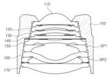
도 1은 본 발명의 제1실시 예에 따른 촬상 광학계의 구성도
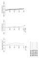
도 2는 도 1에 도시된 촬상 광학계의 수차 곡선
도 3은 도 1에 도시된 촬상 광학계와 렌즈 배럴의 결합 상태도
도 4는 본 발명의 제2실시 예에 따른 촬상 광학계의 구성도
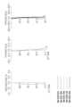
도 5는 도 4에 도시된 촬상 광학계의 수차 곡선
도 6은 도 4에 도시된 촬상 광학계와 렌즈 배럴의 결합 상태도
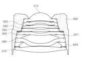
도 7은 본 발명의 제3실시 예에 따른 촬상 광학계의 구성도
도 8은 도 7에 도시된 촬상 광학계의 수차 곡선
도 9는 도 7에 도시된 촬상 광학계와 렌즈 배럴의 결합 상태도
도 10은 본 발명의 제4실시 예에 따른 촬상 광학계의 구성도
도 11은 도 10에 도시된 촬상 광학계의 수차 곡선
도 12는 도 10에 도시된 촬상 광학계와 렌즈 배럴의 결합 상태도
도 13은 본 발명의 제5실시 예에 따른 촬상 광학계의 구성도
도 14는 도 13에 도시된 촬상 광학계의 수차 곡선
도 15는 도 13에 도시된 촬상 광학계와 렌즈 배럴의 결합 상태도Figure 1 is a configuration diagram of an imaging optical system according to the first embodiment of the present invention.
Figure 2 is an aberration curve of the imaging optical system shown in Figure 1.
Figure 3 is a diagram showing the combined state of the imaging optical system and lens barrel shown in Figure 1.
Figure 4 is a configuration diagram of an imaging optical system according to a second embodiment of the present invention.
Figure 5 is an aberration curve of the imaging optical system shown in Figure 4.
Figure 6 is a diagram showing the combined state of the imaging optical system and lens barrel shown in Figure 4.
Figure 7 is a configuration diagram of an imaging optical system according to a third embodiment of the present invention.
Fig. 8 is an aberration curve of the imaging optical system shown in Fig. 7.
Figure 9 is a diagram showing the combined state of the imaging optical system and lens barrel shown in Figure 7.
Figure 10 is a configuration diagram of an imaging optical system according to the fourth embodiment of the present invention.
Fig. 11 is an aberration curve of the imaging optical system shown in Fig. 10.
Figure 12 is a diagram showing the combined state of the imaging optical system and lens barrel shown in Figure 10.
Figure 13 is a configuration diagram of an imaging optical system according to the fifth embodiment of the present invention.
Fig. 14 is an aberration curve of the imaging optical system shown in Fig. 13.
Figure 15 is a diagram showing the combined state of the imaging optical system and lens barrel shown in Figure 13.
이하, 본 발명의 바람직한 실시 예를 첨부된 예시도면에 의거하여 상세히 설명한다.Hereinafter, preferred embodiments of the present invention will be described in detail based on the attached exemplary drawings.
아래에서 본 발명을 설명함에 있어서, 본 발명의 구성요소를 지칭하는 용어들은 각각의 구성요소들의 기능을 고려하여 명명된 것이므로, 본 발명의 기술적 구성요소를 한정하는 의미로 이해되어서는 안 될 것이다.In describing the present invention below, terms referring to components of the present invention are named in consideration of the functions of each component, and therefore should not be understood to limit the technical components of the present invention.
아울러, 명세서 전체에서, 어떤 구성이 다른 구성과 '연결'되어 있다 함은 이들 구성들이 '직접적으로 연결'되어 있는 경우뿐만 아니라, 다른 구성을 사이에 두고 '간접적으로 연결'되어 있는 경우도 포함하는 것을 의미한다. 또한, 어떤 구성요소를 '포함'한다는 것은, 특별히 반대되는 기재가 없는 한 다른 구성요소를 제외하는 것이 아니라 다른 구성요소를 더 포함할 수 있다는 것을 의미한다.In addition, throughout the specification, when a component is said to be 'connected' to another component, it means not only that these components are 'directly connected', but also that they are 'indirectly connected' with other components in between. Also, when a component is said to 'include', it means that other components may be included, rather than excluding other components, unless otherwise specifically stated.
본 명세서에서 제1렌즈는 물체(또는 피사체)와 가장 가까운 렌즈를 의미하고, 제7렌즈는 상면(또는 이미지 센서)과 가장 가까운 렌즈를 의미한다. 본 명세서에서 렌즈의 곡률 반지름(Radius), 두께(Thickness), TTL(제1렌즈의 물체 측면으로부터 상면까지 거리), IMG_HT(상면의 대각길이의 1/2), 초점거리의 단위는 ㎜이다.In this specification, the first lens means the lens closest to the object (or subject), and the seventh lens means the lens closest to the image plane (or image sensor). In this specification, the units of the lens curvature radius (Radius), thickness (Thickness), TTL (the distance from the object side of the first lens to the image plane), IMG_HT (1/2 of the diagonal length of the image plane), and focal length are mm.
렌즈의 두께, 렌즈 간의 간격, TTL은 렌즈의 광축에서의 거리이다. 아울러, 렌즈의 형상에 대한 설명에서 일면이 볼록한 형상이라는 의미는 해당 면의 근축 부분(paraxial region)이 볼록하다는 의미이고, 일면이 오목한 형상이라는 의미는 해당 면의 근축 부분이 오목하다는 의미이다. 따라서, 렌즈의 일면이 볼록한 형상이라고 설명되어도, 렌즈의 가장자리 부분은 오목할 수 있다. 마찬가지로, 렌즈의 일면이 오목한 형상이라고 설명되어도, 렌즈의 가장자리 부분은 볼록할 수 있다.The thickness of the lens, the gap between the lenses, and TTL are the distances from the optical axis of the lens. In addition, in the description of the shape of the lens, the meaning of a convex shape on one side means that the paraxial region of the corresponding surface is convex, and the meaning of a concave shape on one side means that the paraxial region of the corresponding surface is concave. Therefore, even if one side of the lens is described as a convex shape, the edge of the lens can be concave. Likewise, even if one side of the lens is described as a concave shape, the edge of the lens can be convex.
촬상 광학계는 7매의 렌즈를 포함한다. 예를 들어, 촬상 광학계는 물체 측으로부터 순차적으로 배치되는 제1렌즈, 제2렌즈, 제3렌즈, 제4렌즈, 제5렌즈, 제6렌즈, 제7렌즈를 포함할 수 있다. 제1렌즈 내지 제7렌즈는 소정의 간격을 두고 배치된다. 예를 들어, 각각의 렌즈는 근축 부분에서 이웃한 렌즈의 상 측면 및 물체 측면은 접촉하지 않는다. 따라서, 첨부된 도면에서 일 측 렌즈의 상 측면과 타 측 렌즈의 물체 측면이 접한 것으로 도시되어 있더라도, 실제로는 두 렌즈 간의 상 측면과 물체 측면이 접촉하지 않는다.The imaging optical system includes seven lenses. For example, the imaging optical system may include a first lens, a second lens, a third lens, a fourth lens, a fifth lens, a sixth lens, and a seventh lens, which are arranged sequentially from the object side. The first to seventh lenses are arranged at predetermined intervals. For example, the image-side surface and the object-side surface of each lens do not contact each other at the paraxial portion. Therefore, even if the image-side surface of one lens and the object-side surface of the other lens are illustrated as being in contact in the attached drawing, in reality, the image-side surface and the object-side surface between the two lenses do not contact each other.
제1렌즈는 굴절력을 가진다. 예를 들어, 제1렌즈는 정의 굴절력을 가진다. 제1렌즈는 일면이 볼록한 형상이다. 예를 들어, 제1렌즈는 물체 측면이 볼록한 형상이다.The first lens has refractive power. For example, the first lens has positive refractive power. The first lens has a convex shape on one side. For example, the first lens has a convex shape on the object side.
제1렌즈는 비구면을 포함한다. 예를 들어, 제1렌즈는 양면이 모두 비구면일 수 있다. 제1렌즈는 광 투과율이 높고 가공성이 우수한 재질로 제작될 수 있다. 예를 들어, 제1렌즈는 플라스틱 재질로 제작될 수 있다. 제1렌즈는 낮은 굴절률을 갖는다. 예를 들어, 제1렌즈의 굴절률은 1.6 미만일 수 있다.The first lens includes an aspherical surface. For example, both surfaces of the first lens may be aspherical. The first lens may be made of a material having high light transmittance and excellent processability. For example, the first lens may be made of a plastic material. The first lens has a low refractive index. For example, the refractive index of the first lens may be less than 1.6.
제2렌즈는 굴절력을 가진다. 예를 들어, 제2렌즈는 부의 굴절력을 가질 수 있다. 제2렌즈는 일면이 볼록한 형상이다. 예를 들어, 제2렌즈는 물체 측면이 볼록한 형상일 수 있다.The second lens has refractive power. For example, the second lens may have negative refractive power. The second lens has a convex shape on one side. For example, the second lens may have a convex shape on the object side.
제2렌즈는 비구면을 포함한다. 예를 들어, 제2렌즈는 물체 측면이 비구면일 수 있다. 제2렌즈는 광 투과율이 높고 가공성이 우수한 재질로 제작될 수 있다. 예를 들어, 제2렌즈는 플라스틱 재질로 제작될 수 있다. 제2렌즈는 제1렌즈보다 높은 굴절률을 갖는다. 일 예로, 제2렌즈의 굴절률은 1.6 이상일 수 있다. 아울러, 제1렌즈 및 제2렌즈에 의한 수차 개선효과를 극대화시키기 위해 제1렌즈의 굴절률과 제2렌즈의 굴절률 차이는 ±0.1 이상일 수 있다. 예를 들어, 제1렌즈의 굴절률이 1.55 이하면, 제2렌즈의 굴절률은 1.65 이상일 수 있다.The second lens includes an aspherical surface. For example, the object-side surface of the second lens may be aspherical. The second lens may be made of a material having high light transmittance and excellent processability. For example, the second lens may be made of a plastic material. The second lens has a higher refractive index than the first lens. For example, the refractive index of the second lens may be 1.6 or greater. In addition, in order to maximize the aberration improvement effect by the first lens and the second lens, the difference between the refractive index of the first lens and the refractive index of the second lens may be ±0.1 or greater. For example, when the refractive index of the first lens is 1.55 or less, the refractive index of the second lens may be 1.65 or greater.
제3렌즈는 굴절력을 가진다. 제3렌즈는 일 면이 볼록한 형상이다. 예를 들어, 제3렌즈는 물체 측면이 볼록한 형상일 수 있다.The third lens has refractive power. The third lens has a convex shape on one side. For example, the third lens may have a convex shape on the object side.
제3렌즈는 비구면을 포함한다. 예를 들어, 제3렌즈는 상 측면이 비구면일 수 있다. 제3렌즈는 광 투과율이 높고 가공성이 우수한 재질로 제작될 수 있다. 예를 들어, 제3렌즈는 플라스틱 재질로 제작될 수 있다. 제3렌즈는 제1렌즈와 대체로 유사한 굴절률을 갖는다. 예를 들어, 제3렌즈의 굴절률은 1.6 미만일 수 있다. 아울러, 제2렌즈 및 제3렌즈에 의한 수차 개선효과를 극대화시키기 위해 제2렌즈의 굴절률과 제3렌즈의 굴절률 차이는 ±0.1 이상일 수 있다. 예를 들어, 제2렌즈의 굴절률이 1.65 이상이라면, 제3렌즈의 굴절률은 1.55 이하일 수 있다.The third lens includes an aspherical surface. For example, the third lens may have an aspherical image side. The third lens may be made of a material having high light transmittance and excellent processability. For example, the third lens may be made of a plastic material. The third lens has a refractive index that is generally similar to that of the first lens. For example, the refractive index of the third lens may be less than 1.6. In addition, in order to maximize the aberration improvement effect by the second lens and the third lens, the difference between the refractive index of the second lens and the refractive index of the third lens may be ±0.1 or more. For example, if the refractive index of the second lens is 1.65 or more, the refractive index of the third lens may be 1.55 or less.
제4렌즈는 굴절력을 가진다. 예를 들어, 제4렌즈는 부의 굴절력을 가진다. 제4렌즈는 일면이 볼록한 형상이다. 예를 들어, 제4렌즈는 물체 측면 또는 상 측면이 볼록한 형상일 수 있다.The fourth lens has refractive power. For example, the fourth lens has negative refractive power. The fourth lens has a convex shape on one side. For example, the fourth lens may have a convex shape on the object side or the image side.
제4렌즈는 비구면을 포함한다. 예를 들어, 제4렌즈는 양면이 모두 비구면일 수 있다. 제4렌즈는 광 투과율이 높고 가공성이 우수한 재질로 제작될 수 있다. 예를 들어, 제4렌즈는 플라스틱 재질로 제작될 수 있다. 제4렌즈는 제2렌즈와 대체로 동일 또는 유사한 굴절률을 갖는다. 예를 들어, 제4렌즈의 굴절률은 1.6 또는 1.65 이상일 수 있다.The fourth lens includes an aspherical surface. For example, both surfaces of the fourth lens may be aspherical. The fourth lens may be made of a material having high light transmittance and excellent processability. For example, the fourth lens may be made of a plastic material. The fourth lens has a refractive index that is substantially the same or similar to that of the second lens. For example, the refractive index of the fourth lens may be 1.6 or 1.65 or higher.
제5렌즈는 굴절력을 가진다. 제5렌즈는 일면이 볼록한 형상이다. 예를 들어, 제5렌즈는 물체 측면 또는 상 측면이 볼록한 형상일 수 있다.The fifth lens has refractive power. The fifth lens has a convex shape on one side. For example, the fifth lens may have a convex shape on the object side or the image side.
제5렌즈는 비구면을 포함한다. 예를 들어, 제5렌즈는 양면이 모두 비구면일 수 있다. 제5렌즈는 광 투과율이 높고 가공성이 우수한 재질로 제작될 수 있다. 예를 들어, 제5렌즈는 플라스틱 재질로 제작될 수 있다. 제5렌즈는 제4렌즈와 대체로 동일 또는 유사한 굴절률을 갖는다. 예를 들어, 제5렌즈의 굴절률은 1.6 또는 1.65 이상일 수 있다.The fifth lens includes an aspherical surface. For example, both surfaces of the fifth lens may be aspherical. The fifth lens may be made of a material having high light transmittance and excellent processability. For example, the fifth lens may be made of a plastic material. The fifth lens has a refractive index that is substantially the same as or similar to that of the fourth lens. For example, the refractive index of the fifth lens may be 1.6 or 1.65 or higher.
제6렌즈는 굴절력을 가진다. 예를 들어, 제6렌즈는 부의 굴절력을 갖는다. 제6렌즈는 일 면이 볼록한 형상이다. 예를 들어, 제6렌즈는 물체 측면 또는 상 측면이 볼록한 형상일 수 있다. 제6렌즈는 변곡점을 갖는 형상일 수 있다. 예를 들어, 제6렌즈의 물체 측면 및 상 측면 중 적어도 일면에는 변곡점이 형성될 수 있다.The sixth lens has refractive power. For example, the sixth lens has negative refractive power. The sixth lens has a shape in which one surface is convex. For example, the sixth lens may have a shape in which the object-side surface or the image-side surface is convex. The sixth lens may have a shape having an inflection point. For example, an inflection point may be formed on at least one surface of the object-side surface and the image-side surface of the sixth lens.
제6렌즈는 비구면을 포함한다. 예를 들어, 제6렌즈는 양면이 모두 비구면일 수 있다. 제6렌즈는 광 투과율이 높고 가공성이 우수한 재질로 제작될 수 있다. 예를 들어, 제6렌즈는 플라스틱 재질로 제작될 수 있다. 제6렌즈는 제1렌즈와 대체로 동일 또는 유사한 굴절률을 갖는다. 예를 들어, 제6렌즈의 굴절률은 1.6 미만일 수 있다.The sixth lens includes an aspherical surface. For example, both surfaces of the sixth lens may be aspherical. The sixth lens may be made of a material having high light transmittance and excellent processability. For example, the sixth lens may be made of a plastic material. The sixth lens has a refractive index that is substantially the same or similar to that of the first lens. For example, the refractive index of the sixth lens may be less than 1.6.
제7렌즈는 굴절력을 가진다. 예를 들어, 제7렌즈는 정의 굴절력을 갖는다. 제7렌즈는 적어도 일면이 볼록한 형상일 수 있다. 예를 들어, 제7렌즈는 물체 측면 및 상 측면이 모두 볼록한 형상일 수 있다.The seventh lens has refractive power. For example, the seventh lens has positive refractive power. The seventh lens may have a shape in which at least one surface is convex. For example, the seventh lens may have a shape in which both the object-side surface and the image-side surface are convex.
제7렌즈는 비구면을 포함한다. 예를 들어, 제7렌즈는 양면이 모두 비구면일 수 있다. 제7렌즈는 광 투과율이 높고 가공성이 우수한 재질로 제작될 수 있다. 예를 들어, 제7렌즈는 플라스틱 재질로 제작될 수 있다. 제7렌즈는 제5렌즈와 대체로 유사한 굴절률을 갖는다. 예를 들어, 제7렌즈의 굴절률은 1.6 또는 1.65 이상일 수 있다.The seventh lens includes an aspherical surface. For example, both surfaces of the seventh lens may be aspherical. The seventh lens may be made of a material having high light transmittance and excellent processability. For example, the seventh lens may be made of a plastic material. The seventh lens has a refractive index that is generally similar to that of the fifth lens. For example, the refractive index of the seventh lens may be 1.6 or 1.65 or higher.
제1렌즈 내지 제7렌즈는 전술한 바와 같이 비구면을 포함한다. 제1렌즈 내지 제7렌즈의 비구면은 수학식 1로 표현될 수 있다.The first to seventh lenses include aspherical surfaces as described above. The aspherical surfaces of the first to seventh lenses can be expressed by mathematical expression 1.
수학식 1에서 c는 해당 렌즈의 곡률 반지름의 역수이고, k는 코닉 상수이고, r은 비구면 상의 임의의 점으로부터 광축까지의 거리이고, A ~ J는 비구면 상수이고, Z(또는 SAG)는 비구면 상의 임의의 점으로부터 해당 비구면의 정점까지의 광축 방향으로의 높이이다.In mathematical expression 1, c is the reciprocal of the radius of curvature of the lens, k is the conic constant, r is the distance from any point on the aspheric surface to the optical axis, A to J are aspheric constants, and Z (or SAG) is the height in the direction of the optical axis from any point on the aspheric surface to the vertex of the aspheric surface.
촬상 광학계는 필터, 이미지 센서, 조리개를 더 포함한다.The imaging optics further include a filter, an image sensor, and an aperture.
필터는 제7렌즈와 이미지 센서 사이에 배치된다. 필터는 일부 파장의 빛을 차단할 수 있다. 예를 들어, 필터는 적외선 파장의 빛을 차단할 수 있다. 이미지 센서는 상면을 형성한다. 예를 들어, 이미지 센서의 표면은 상면을 형성할 수 있다. 조리개는 렌즈로 입사되는 광량을 조정하도록 배치된다. 예를 들어, 조리개는 제1렌즈와 제2렌즈 사이에 배치될 수 있다.A filter is arranged between the seventh lens and the image sensor. The filter can block light of some wavelengths. For example, the filter can block light of infrared wavelengths. The image sensor forms an image surface. For example, a surface of the image sensor can form the image surface. An aperture is arranged to adjust the amount of light incident on the lens. For example, the aperture can be arranged between the first lens and the second lens.
촬상 광학계는 아래의 조건식들 중 하나 이상을 만족할 수 있다.The imaging optical system can satisfy one or more of the following conditions.
[조건식 1]TTL/f < 1.0[Condition 1] TTL/f < 1.0
[조건식 2]D23/D34 < 1.2[Condition 2] D23/D34 < 1.2
[조건식 3]1.9 < TTL/(IMG_HT) < 2.2[Condition 3] 1.9 < TTL/(IMG_HT) < 2.2
[조건식 4]0.15 < D56/TTL[Condition 4] 0.15 < D56/TTL
[조건식 5]D12 < D45[Condition 5] D12 < D45
[조건식 6]12 < D56/D12[Condition 6] 12 < D56/D12
[조건식 7]-10 < f345 < - 3.02[Condition 7] -10 < f345 < - 3.02
상기 조건식에서 f는 촬상 광학계의 전체 초점거리이고, TTL은 제1렌즈의 물체 측면으로부터 상면까지의 거리이고, D12는 제1렌즈의 상 측면으로부터 제2렌즈의 물체 측면까지의 거리이고, D23은 제2렌즈의 상 측면으로부터 제3렌즈의 물체 측면까지의 거리이고, D34는 제3렌즈의 상 측면으로부터 제4렌즈의 물체 측면까지의 거리이고, D45는 제4렌즈의 상 측면으로부터 제5렌즈의 물체 측면까지의 거리이고, D56은 제5렌즈의 상 측면으로부터 제6렌즈의 물체 측면까지의 거리이고, IMG_HT는 상면의 대각길이의 1/2이고, f345는 제3렌즈 내지 제5렌즈의 합초점거리이다.In the above conditional expression, f is the total focal length of the imaging optical system, TTL is the distance from the object-side surface of the first lens to the image plane, D12 is the distance from the image-side surface of the first lens to the object-side surface of the second lens, D23 is the distance from the image-side surface of the second lens to the object-side surface of the third lens, D34 is the distance from the image-side surface of the third lens to the object-side surface of the fourth lens, D45 is the distance from the image-side surface of the fourth lens to the object-side surface of the fifth lens, D56 is the distance from the image-side surface of the fifth lens to the object-side surface of the sixth lens, IMG_HT is 1/2 of the diagonal length of the image plane, and f345 is the combined focal length of the third to fifth lenses.
촬상 광학계는 아래의 조건식들 중 하나 이상을 만족할 수 있다.The imaging optical system can satisfy one or more of the following conditions.
[조건식 8] 0.1 <L1w/L7w < 0.5[Condition 8] 0.1 <L1w/L7w < 0.5
[조건식 9] 0.4 < L1TR/L7TR < 0.7[Condition 9] 0.4 < L1TR/L7TR < 0.7
[조건식 10] 0.5 < L1234TRavg/L7TR < 0.75[Condition 10] 0.5 < L1234TRavg/L7TR < 0.75
[조건식 11] 0.5 < L12345TRavg/L7TR < 0.8[Condition 11] 0.5 < L12345TRavg/L7TR < 0.8
상기 조건식에서 L1w는 제1 렌즈의 무게[mg]이고, L7w는 제7렌즈의 무게[mg]이고, L1TR은 제1렌즈의 최대 직경[mm]이고, L7TR은 제7렌즈의 최대 직경[mm]이고, L1234TRavg은 제1렌즈 내지 제4렌즈의 최대 직경의 평균값[mm]이고, L12345TRavg는 제1렌즈 내지 제5렌즈의 최대 직경의 평균값[mm]이다. 참고로, 렌즈의 최대 직경은 렌즈의 리브를 포함한 직경을 의미한다.In the above conditional expression, L1w is the weight of the first lens [mg], L7w is the weight of the seventh lens [mg], L1TR is the maximum diameter of the first lens [mm], L7TR is the maximum diameter of the seventh lens [mm], L1234TRavg is the average value of the maximum diameters of the first to fourth lenses [mm], and L12345TRavg is the average value of the maximum diameters of the first to fifth lenses [mm]. For reference, the maximum diameter of the lens means the diameter including the rib of the lens.
조건식 8 및 조건식 9는 렌즈들 간의 자가정렬(self align)과 배럴에 의한 정렬을 용이하게 하기 위한 제1렌즈와 제7렌즈 간의 무게 비율 및 외경비율을 제공한다. 조건식 10 및 조건식 11은 수차 보정을 용이하게 하기 위한 렌즈들 간의 외경 비율을 제공한다.Conditions 8 and 9 provide the weight ratio and outer diameter ratio between the first lens and the seventh lens to facilitate self-alignment between the lenses and alignment by the barrel. Conditions 10 and 11 provide the outer diameter ratio between the lenses to facilitate aberration correction.
다음에서는 여러 실시 예에 따른 촬상 광학계를 설명한다.In the following, imaging optical systems according to various embodiments are described.
먼저, 도 1을 참조하여 제1실시 예에 따른 촬상 광학계를 설명한다.First, an imaging optical system according to a first embodiment will be described with reference to FIG. 1.
촬상 광학계(100)는 제1렌즈(110), 제2렌즈(120), 제3렌즈(130), 제4렌즈(140), 제5렌즈(150), 제6렌즈(160), 제7렌즈(170)를 포함한다.The imaging optical system (100) includes a first lens (110), a second lens (120), a third lens (130), a fourth lens (140), a fifth lens (150), a sixth lens (160), and a seventh lens (170).
제1렌즈(110)는 정의 굴절력을 가지며, 물체 측면이 볼록하고 상 측면이 볼록한 형상이다. 제2렌즈(120)는 부의 굴절력을 가지며, 물체 측면이 볼록하고 상 측면이 오목한 형상이다. 제3렌즈(130)는 부의 굴절력을 가지며, 물체 측면이 볼록하고 상 측면이 오목한 형상이다. 제4렌즈(140)는 부의 굴절력을 가지며, 물체 측면이 볼록하고 상 측면이 오목한 형상이다. 제5렌즈(150)는 부의 굴절력을 가지며, 물체 측면이 볼록하고 상 측면이 오목한 형상이다. 제6렌즈(160)는 부의 굴절력을 가지며, 물체 측면이 오목하고 상 측면이 볼록한 형상이다. 아울러, 제6렌즈(160)는 물체 측면 및 상 측면 중 적어도 일면에 변곡점이 형성되는 형상이다. 제7렌즈(170)는 정의 굴절력을 가지며, 물체 측면이 볼록하고 상 측면이 볼록한 형상이다.The first lens (110) has positive refractive power, and has a shape in which the object side surface is convex and the image side surface is convex. The second lens (120) has negative refractive power, and has a shape in which the object side surface is convex and the image side surface is concave. The third lens (130) has negative refractive power, and has a shape in which the object side surface is convex and the image side surface is concave. The fourth lens (140) has negative refractive power, and has a shape in which the object side surface is convex and the image side surface is concave. The fifth lens (150) has negative refractive power, and has a shape in which the object side surface is convex and the image side surface is concave. The sixth lens (160) has negative refractive power, and has a shape in which the object side surface is concave and the image side surface is convex. In addition, the sixth lens (160) has a shape in which an inflection point is formed on at least one of the object side surface and the image side surface. The seventh lens (170) has a defined refractive power and is shaped such that the object side is convex and the image side is convex.
촬상 광학계(100)는 필터(180), 이미지 센서(190)를 더 포함한다. 필터(180)는 제7렌즈(170)와 이미지 센서(190) 사이에 배치된다. 조리개는 표 1에서 알 수 있듯이 제4렌즈와 제5렌즈 사이에 배치된다.The imaging optical system (100) further includes a filter (180) and an image sensor (190). The filter (180) is positioned between the seventh lens (170) and the image sensor (190). The aperture is positioned between the fourth lens and the fifth lens, as can be seen in Table 1.
위와 같이 구성된 촬상 광학계는 도 2에 도시된 바와 같은 수차 특성을 나타낸다. 촬상 광학계는 도 3에 도시된 바와 같이 렌즈 배럴(102)과 결합한다. 촬상 광학계에서 제1렌즈(110) 내지 제4렌즈(140)는 상호 결합에 의해 광축이 정렬된다. 여기서, 제2렌즈(120) 내지 제4렌즈(140)의 가장자리는 렌즈 배럴(102)의 내주면과 대체로 접촉하지 않는다. 촬상 광학계에서 제5렌즈(150) 내지 제7렌즈(170)는 렌즈 배럴(102)과 결합하여 광축이 정렬된다. 즉, 제5렌즈(150) 내지 제7렌즈(170)는 렌즈 배럴(102)의 내주면과 접촉한다. 렌즈와 렌즈 사이에는 차광부재가 배치된다. 아울러, 제5렌즈와 제6렌즈 사이 및 제6렌즈 및 제7렌즈 사이에는 간격 유지 부재(SP1, SP2)가 배치된다.The imaging optical system configured as above exhibits aberration characteristics as illustrated in FIG. 2. The imaging optical system is coupled with the lens barrel (102) as illustrated in FIG. 3. In the imaging optical system, the first lens (110) to the fourth lens (140) are aligned with their optical axes by mutual coupling. Here, the edges of the second lens (120) to the fourth lens (140) generally do not contact the inner surface of the lens barrel (102). In the imaging optical system, the fifth lens (150) to the seventh lens (170) are coupled with the lens barrel (102) so that their optical axes are aligned. That is, the fifth lens (150) to the seventh lens (170) are in contact with the inner surface of the lens barrel (102). A light-blocking member is arranged between the lenses. In addition, a spacing member (SP1, SP2) is arranged between the fifth lens and the sixth lens and between the sixth lens and the seventh lens.
표 1 및 표 2는 본 실시 예에 따른 촬상 광학계의 렌즈 특성 및 비구면 값을 나타낸다.Tables 1 and 2 show the lens characteristics and aspheric values of the imaging optical system according to the present embodiment.
도 3을 참조하여 제2실시 예에 따른 촬상 광학계를 설명한다.An imaging optical system according to a second embodiment is described with reference to FIG. 3.
촬상 광학계(200)는 제1렌즈(210), 제2렌즈(220), 제3렌즈(230), 제4렌즈(240), 제5렌즈(250), 제6렌즈(260), 제7렌즈(270)를 포함한다.The imaging optical system (200) includes a first lens (210), a second lens (220), a third lens (230), a fourth lens (240), a fifth lens (250), a sixth lens (260), and a seventh lens (270).
제1렌즈(210)는 정의 굴절력을 가지며, 물체 측면이 볼록하고 상 측면이 볼록한 형상이다. 제2렌즈(220)는 부의 굴절력을 가지며, 물체 측면이 볼록하고 상 측면이 오목한 형상이다. 제3렌즈(230)는 부의 굴절력을 가지며, 물체 측면이 볼록하고 상 측면이 오목한 형상이다. 제4렌즈(240)는 부의 굴절력을 가지며, 물체 측면이 오목하고 상 측면이 볼록한 형상이다. 제5렌즈(250)는 부의 굴절력을 가지며, 물체 측면이 오목하고 상 측면이 볼록한 형상이다. 제6렌즈(260)는 부의 굴절력을 가지며, 물체 측면이 오목하고 상 측면이 볼록한 형상이다. 아울러, 제6렌즈(260)는 물체 측면 및 상 측면 중 적어도 일면에 변곡점이 형성되는 형상이다. 제7렌즈(270)는 정의 굴절력을 가지며, 물체 측면이 볼록하고 상 측면이 볼록한 형상이다.The first lens (210) has positive refractive power, and has a shape in which the object side surface is convex and the image side surface is convex. The second lens (220) has negative refractive power, and has a shape in which the object side surface is convex and the image side surface is concave. The third lens (230) has negative refractive power, and has a shape in which the object side surface is convex and the image side surface is concave. The fourth lens (240) has negative refractive power, and has a shape in which the object side surface is concave and the image side surface is convex. The fifth lens (250) has negative refractive power, and has a shape in which the object side surface is concave and the image side surface is convex. The sixth lens (260) has negative refractive power, and has a shape in which the object side surface is concave and the image side surface is convex. In addition, the sixth lens (260) has a shape in which an inflection point is formed on at least one of the object side surface and the image side surface. The seventh lens (270) has a defined refractive power and is shaped such that the object side is convex and the image side is convex.
촬상 광학계(200)는 필터(280), 이미지 센서(290)를 더 포함한다. 필터(280)는 제7렌즈(270)와 이미지 센서(290) 사이에 배치된다. 조리개는 표 3에서 알 수 있듯이 제3렌즈와 제4렌즈 사이에 배치된다.The imaging optical system (200) further includes a filter (280) and an image sensor (290). The filter (280) is positioned between the seventh lens (270) and the image sensor (290). The aperture is positioned between the third lens and the fourth lens, as can be seen in Table 3.
위와 같이 구성된 촬상 광학계는 도 5에 도시된 바와 같은 수차 특성을 나타낸다. 촬상 광학계는 도 6에 도시된 바와 같이 렌즈 배럴(202)과 결합한다. 촬상 광학계에서 제1렌즈(210) 내지 제4렌즈(240)는 상호 결합에 의해 광축이 정렬된다. 여기서, 제2렌즈(220) 내지 제4렌즈(240)의 가장자리는 렌즈 배럴(202)의 내주면과 대체로 접촉하지 않는다. 촬상 광학계에서 제5렌즈(250) 내지 제7렌즈(270)는 렌즈 배럴(202)과 결합하여 광축이 정렬된다. 즉, 제5렌즈(250) 내지 제7렌즈(270)는 렌즈 배럴(202)의 내주면과 접촉한다. 렌즈와 렌즈 사이에는 차광부재가 배치된다. 아울러, 제5렌즈와 제6렌즈 사이 및 제6렌즈 및 제7렌즈 사이에는 간격 유지 부재(SP1, SP2)가 배치된다.The imaging optical system configured as above exhibits aberration characteristics as illustrated in FIG. 5. The imaging optical system is coupled with the lens barrel (202) as illustrated in FIG. 6. In the imaging optical system, the first lens (210) to the fourth lens (240) are aligned with their optical axes by mutual coupling. Here, the edges of the second lens (220) to the fourth lens (240) generally do not contact the inner surface of the lens barrel (202). In the imaging optical system, the fifth lens (250) to the seventh lens (270) are coupled with the lens barrel (202) so that their optical axes are aligned. That is, the fifth lens (250) to the seventh lens (270) are in contact with the inner surface of the lens barrel (202). A light-blocking member is arranged between the lenses. In addition, a spacing member (SP1, SP2) is arranged between the fifth lens and the sixth lens and between the sixth lens and the seventh lens.
표 3 및 표 4는 본 실시 예에 따른 촬상 광학계의 렌즈 특성 및 비구면 값을 나타낸다.Tables 3 and 4 show the lens characteristics and aspherical values of the imaging optical system according to the present embodiment.
도 7을 참조하여 제3실시 예에 따른 촬상 광학계를 설명한다.An imaging optical system according to a third embodiment is described with reference to FIG. 7.
촬상 광학계(300)는 제1렌즈(310), 제2렌즈(320), 제3렌즈(330), 제4렌즈(340), 제5렌즈(350), 제6렌즈(360), 제7렌즈(370)를 포함한다.The imaging optical system (300) includes a first lens (310), a second lens (320), a third lens (330), a fourth lens (340), a fifth lens (350), a sixth lens (360), and a seventh lens (370).
제1렌즈(310)는 정의 굴절력을 가지며, 물체 측면이 볼록하고 상 측면이 볼록한 형상이다. 제2렌즈(320)는 부의 굴절력을 가지며, 물체 측면이 볼록하고 상 측면이 오목한 형상이다. 제3렌즈(330)는 부의 굴절력을 가지며, 물체 측면이 볼록하고 상 측면이 오목한 형상이다. 제4렌즈(340)는 부의 굴절력을 가지며, 물체 측면이 오목하고 상 측면이 볼록한 형상이다. 제5렌즈(350)는 정의 굴절력을 가지며, 물체 측면이 오목하고 상 측면이 볼록한 형상이다. 제6렌즈(360)는 부의 굴절력을 가지며, 물체 측면이 오목하고 상 측면이 볼록한 형상이다. 아울러, 제6렌즈(360)는 물체 측면 및 상 측면 중 적어도 일면에 변곡점이 형성되는 형상이다. 제7렌즈(370)는 정의 굴절력을 가지며, 물체 측면이 볼록하고 상 측면이 볼록한 형상이다.The first lens (310) has positive refractive power, and has a shape in which the object side surface is convex and the image side surface is convex. The second lens (320) has negative refractive power, and has a shape in which the object side surface is convex and the image side surface is concave. The third lens (330) has negative refractive power, and has a shape in which the object side surface is convex and the image side surface is concave. The fourth lens (340) has negative refractive power, and has a shape in which the object side surface is concave and the image side surface is convex. The fifth lens (350) has positive refractive power, and has a shape in which the object side surface is concave and the image side surface is convex. The sixth lens (360) has negative refractive power, and has a shape in which the object side surface is concave and the image side surface is convex. In addition, the sixth lens (360) has a shape in which an inflection point is formed on at least one of the object side surface and the image side surface. The seventh lens (370) has positive refractive power, and has a shape in which the object side surface is convex and the image side surface is convex.
촬상 광학계(300)는 필터(380), 이미지 센서(390)를 더 포함한다. 필터(380)는 제7렌즈(370)와 이미지 센서(390) 사이에 배치된다. 조리개는 표 5에서 알 수 있듯이 제2렌즈와 제3렌즈 사이에 배치된다.The imaging optical system (300) further includes a filter (380) and an image sensor (390). The filter (380) is positioned between the seventh lens (370) and the image sensor (390). The aperture is positioned between the second lens and the third lens, as can be seen in Table 5.
위와 같이 구성된 촬상 광학계는 도 8에 도시된 바와 같은 수차 특성을 나타낸다. 촬상 광학계는 도 9에 도시된 바와 같이 렌즈 배럴(302)과 결합한다. 촬상 광학계에서 제1렌즈(310) 내지 제3렌즈(330)는 상호 결합에 의해 광축이 정렬된다. 여기서, 제2렌즈(320) 및 제3렌즈(330)의 가장자리는 렌즈 배럴(302)의 내주면과 대체로 접촉하지 않는다. 촬상 광학계에서 제4렌즈(340) 내지 제7렌즈(370)는 렌즈 배럴(302)과 결합하여 광축이 정렬된다. 즉, 제4렌즈(340) 내지 제7렌즈(370)는 렌즈 배럴(302)의 내주면과 접촉한다. 렌즈와 렌즈 사이에는 차광부재가 배치된다. 아울러, 제5렌즈와 제6렌즈 사이 및 제6렌즈 및 제7렌즈 사이에는 간격 유지 부재(SP1, SP2)가 배치된다.The imaging optical system configured as above exhibits aberration characteristics as illustrated in FIG. 8. The imaging optical system is coupled with the lens barrel (302) as illustrated in FIG. 9. In the imaging optical system, the first lens (310) to the third lens (330) are aligned with their optical axes by mutual coupling. Here, the edges of the second lens (320) and the third lens (330) generally do not contact the inner surface of the lens barrel (302). In the imaging optical system, the fourth lens (340) to the seventh lens (370) are coupled with the lens barrel (302) so that their optical axes are aligned. That is, the fourth lens (340) to the seventh lens (370) are in contact with the inner surface of the lens barrel (302). A light-blocking member is arranged between the lenses. In addition, a spacing member (SP1, SP2) is arranged between the fifth lens and the sixth lens and between the sixth lens and the seventh lens.
표 5 및 표 6은 본 실시 예에 따른 촬상 광학계의 렌즈 특성 및 비구면 값을 나타낸다.Tables 5 and 6 show the lens characteristics and aspherical values of the imaging optical system according to the present embodiment.
도 10을 참조하여 제4실시 예에 따른 촬상 광학계를 설명한다.An imaging optical system according to a fourth embodiment is described with reference to FIG. 10.
촬상 광학계(400)는 제1렌즈(410), 제2렌즈(420), 제3렌즈(430), 제4렌즈(440), 제5렌즈(450), 제6렌즈(460), 제7렌즈(470)를 포함한다.The imaging optical system (400) includes a first lens (410), a second lens (420), a third lens (430), a fourth lens (440), a fifth lens (450), a sixth lens (460), and a seventh lens (470).
제1렌즈(410)는 정의 굴절력을 가지며, 물체 측면이 볼록하고 상 측면이 볼록한 형상이다. 제2렌즈(420)는 부의 굴절력을 가지며, 물체 측면이 볼록하고 상 측면이 오목한 형상이다. 제3렌즈(430)는 부의 굴절력을 가지며, 물체 측면이 볼록하고 상 측면이 오목한 형상이다. 제4렌즈(440)는 부의 굴절력을 가지며, 물체 측면이 오목하고 상 측면이 볼록한 형상이다. 제5렌즈(450)는 부의 굴절력을 가지며, 물체 측면이 오목하고 상 측면이 볼록한 형상이다. 제6렌즈(460)는 부의 굴절력을 가지며, 물체 측면이 볼록하고 상 측면이 오목한 형상이다. 아울러, 제6렌즈(460)는 물체 측면 및 상 측면 중 적어도 일면에 변곡점이 형성되는 형상이다. 제7렌즈(470)는 정의 굴절력을 가지며, 물체 측면이 볼록하고 상 측면이 볼록한 형상이다.The first lens (410) has positive refractive power, and has a shape in which the object side surface is convex and the image side surface is convex. The second lens (420) has negative refractive power, and has a shape in which the object side surface is convex and the image side surface is concave. The third lens (430) has negative refractive power, and has a shape in which the object side surface is convex and the image side surface is concave. The fourth lens (440) has negative refractive power, and has a shape in which the object side surface is concave and the image side surface is convex. The fifth lens (450) has negative refractive power, and has a shape in which the object side surface is concave and the image side surface is convex. The sixth lens (460) has negative refractive power, and has a shape in which the object side surface is convex and the image side surface is concave. In addition, the sixth lens (460) has a shape in which an inflection point is formed on at least one of the object side surface and the image side surface. The seventh lens (470) has a defined refractive power and is shaped such that the object side is convex and the image side is convex.
촬상 광학계(400)는 필터(480), 이미지 센서(490)를 더 포함한다. 필터(480)는 제7렌즈(470)와 이미지 센서(490) 사이에 배치된다. 조리개는 표 7에서 알 수 있듯이 제2렌즈와 제3렌즈 사이에 배치된다.The imaging optical system (400) further includes a filter (480) and an image sensor (490). The filter (480) is positioned between the seventh lens (470) and the image sensor (490). The aperture is positioned between the second lens and the third lens, as can be seen in Table 7.
위와 같이 구성된 촬상 광학계는 도 11에 도시된 바와 같은 수차 특성을 나타낸다. 촬상 광학계는 도 12에 도시된 바와 같이 렌즈 배럴(402)과 결합한다. 촬상 광학계에서 제1렌즈(410) 내지 제3렌즈(430)는 상호 결합에 의해 광축이 정렬된다. 여기서, 제2렌즈(420) 및 제3렌즈(430)의 가장자리는 렌즈 배럴(402)의 내주면과 대체로 접촉하지 않는다. 촬상 광학계에서 제4렌즈(440) 내지 제7렌즈(470)는 렌즈 배럴(402)과 결합하여 광축이 정렬된다. 즉, 제4렌즈(440) 내지 제7렌즈(470)는 렌즈 배럴(402)의 내주면과 접촉한다. 렌즈와 렌즈 사이에는 차광부재가 배치된다. 아울러, 제5렌즈와 제6렌즈 사이 및 제6렌즈 및 제7렌즈 사이에는 간격 유지 부재(SP1, SP2)가 배치된다.The imaging optical system configured as above exhibits aberration characteristics as illustrated in FIG. 11. The imaging optical system is coupled with a lens barrel (402) as illustrated in FIG. 12. In the imaging optical system, the first lens (410) to the third lens (430) are aligned with their optical axes by mutual coupling. Here, the edges of the second lens (420) and the third lens (430) generally do not contact the inner surface of the lens barrel (402). In the imaging optical system, the fourth lens (440) to the seventh lens (470) are coupled with the lens barrel (402) so that their optical axes are aligned. That is, the fourth lens (440) to the seventh lens (470) contact the inner surface of the lens barrel (402). A light-blocking member is arranged between the lenses. In addition, a spacing member (SP1, SP2) is arranged between the fifth lens and the sixth lens and between the sixth lens and the seventh lens.
표 7 및 표 8은 본 실시 예에 따른 촬상 광학계의 렌즈 특성 및 비구면 값을 나타낸다.Tables 7 and 8 show the lens characteristics and aspherical values of the imaging optical system according to the present embodiment.
도 13을 참조하여 제5실시 예에 따른 촬상 광학계를 설명한다.An imaging optical system according to the fifth embodiment will be described with reference to FIG. 13.
촬상 광학계(500)는 제1렌즈(510), 제2렌즈(520), 제3렌즈(530), 제4렌즈(540), 제5렌즈(550), 제6렌즈(560), 제7렌즈(570)를 포함한다.The imaging optical system (500) includes a first lens (510), a second lens (520), a third lens (530), a fourth lens (540), a fifth lens (550), a sixth lens (560), and a seventh lens (570).
제1렌즈(510)는 정의 굴절력을 가지며, 물체 측면이 볼록하고 상 측면이 오목한 형상이다. 제2렌즈(520)는 부의 굴절력을 가지며, 물체 측면이 볼록하고 상 측면이 오목한 형상이다. 제3렌즈(530)는 정의 굴절력을 가지며, 물체 측면이 볼록하고 상 측면이 오목한 형상이다. 제4렌즈(540)는 부의 굴절력을 가지며, 물체 측면이 오목하고 상 측면이 볼록한 형상이다. 제5렌즈(550)는 부의 굴절력을 가지며, 물체 측면이 오목하고 상 측면이 볼록한 형상이다. 제6렌즈(560)는 부의 굴절력을 가지며, 물체 측면이 볼록하고 상 측면이 오목한 형상이다. 아울러, 제6렌즈(560)는 물체 측면 및 상 측면 중 적어도 일면에 변곡점이 형성되는 형상이다. 제7렌즈(570)는 정의 굴절력을 가지며, 물체 측면이 볼록하고 상 측면이 볼록한 형상이다.The first lens (510) has positive refractive power, and has a shape in which the object side surface is convex and the image side surface is concave. The second lens (520) has negative refractive power, and has a shape in which the object side surface is convex and the image side surface is concave. The third lens (530) has positive refractive power, and has a shape in which the object side surface is convex and the image side surface is concave. The fourth lens (540) has negative refractive power, and has a shape in which the object side surface is concave and the image side surface is convex. The fifth lens (550) has negative refractive power, and has a shape in which the object side surface is concave and the image side surface is convex. The sixth lens (560) has negative refractive power, and has a shape in which the object side surface is convex and the image side surface is concave. In addition, the sixth lens (560) has a shape in which an inflection point is formed on at least one of the object side surface and the image side surface. The seventh lens (570) has positive refractive power, and has a shape in which the object side surface is convex and the image side surface is convex.
촬상 광학계(500)는 필터(580), 이미지 센서(590)를 더 포함한다. 필터(580)는 제7렌즈(570)와 이미지 센서(590) 사이에 배치된다. 조리개는 표 9에서 알 수 있듯이 제2렌즈와 제3렌즈 사이에 배치된다.The imaging optical system (500) further includes a filter (580) and an image sensor (590). The filter (580) is positioned between the seventh lens (570) and the image sensor (590). The aperture is positioned between the second lens and the third lens, as can be seen in Table 9.
위와 같이 구성된 촬상 광학계는 도 14에 도시된 바와 같은 수차 특성을 나타낸다. 촬상 광학계는 도 15에 도시된 바와 같이 렌즈 배럴(502)과 결합한다. 촬상 광학계에서 제1렌즈(510) 내지 제3렌즈(530)는 상호 결합에 의해 광축이 정렬된다. 여기서, 제2렌즈(520) 및 제3렌즈(530)의 가장자리는 렌즈 배럴(502)의 내주면과 대체로 접촉하지 않는다. 촬상 광학계에서 제4렌즈(540) 내지 제7렌즈(570)는 렌즈 배럴(502)과 결합하여 광축이 정렬된다. 즉, 제4렌즈(540) 내지 제7렌즈(570)는 렌즈 배럴(502)의 내주면과 접촉한다. 렌즈와 렌즈 사이에는 차광부재가 배치된다. 아울러, 제5렌즈와 제6렌즈 사이 및 제6렌즈 및 제7렌즈 사이에는 간격 유지 부재(SP1, SP2)가 배치된다.The imaging optical system configured as above exhibits aberration characteristics as illustrated in FIG. 14. The imaging optical system is coupled with a lens barrel (502) as illustrated in FIG. 15. In the imaging optical system, the first lens (510) to the third lens (530) are aligned with their optical axes by mutual coupling. Here, the edges of the second lens (520) and the third lens (530) generally do not contact the inner surface of the lens barrel (502). In the imaging optical system, the fourth lens (540) to the seventh lens (570) are coupled with the lens barrel (502) so that their optical axes are aligned. That is, the fourth lens (540) to the seventh lens (570) contact the inner surface of the lens barrel (502). A light-blocking member is arranged between the lenses. In addition, a spacing member (SP1, SP2) is arranged between the fifth lens and the sixth lens and between the sixth lens and the seventh lens.
표 9 및 표 10은 본 실시 예에 따른 촬상 광학계의 렌즈 특성 및 비구면 값을 나타낸다.Tables 9 and 10 show the lens characteristics and aspherical values of the imaging optical system according to the present embodiment.
표 11 및 표 12는 제1실시 예 내지 제5실시 예에 따른 촬상 광학계의 광학적 특성 값을 나타낸 것이다.Tables 11 and 12 show optical characteristic values of the imaging optical systems according to the first to fifth embodiments.
표 12에서 L1w 내지 L7w는 제1렌즈 내지 제7렌즈의 무게[mg]를 나타내고, L1TR 내지 L7TR은 리브(차양부)를 포함한 제1렌즈 내지 제7렌즈의 최대 직경[mm]을 나타낸다.In Table 12, L1w to L7w represent the weights [mg] of the first to seventh lenses, and L1TR to L7TR represent the maximum diameters [mm] of the first to seventh lenses including the ribs (shades).
표 13 및 표 14는 제1실시 예 내지 제5실시 예에 따른 촬상 광학계의 조건식 값을 나타낸다.Tables 13 and 14 show conditional expression values of the imaging optical system according to the first to fifth embodiments.
L7TRL1234TRavg/
L7TR
L7TRL12345TRavg/
L7TR
본 발명에 따른 촬상 광학계는 대체로 다음과 같은 광학 특성을 가질 수 있다. 예를 들어, 촬상 광학계의 전체 길이(TTL)는 5.5 ~ 6.0 mm의 범위에서 결정되고, 전체 초점거리는 6.0 ~ 7.2 mm의 범위에서 결정되고, 제1렌즈의 초점거리는 2.3 ~ 3.2 mm의 범위에서 결정되고, 제2렌즈의 초점거리는 -9.0 ~ -4.0 mm의 범위에서 결정되고, 제3렌즈의 초점거리는 -10 mm 이하 또는 100 mm 이상의 범위에서 결정되고, 제4렌즈의 초점거리는 -20 ~ -6.0 mm 범위에서 결정되고, 제5렌즈의 초점거리는 -7 mm 이하 또는 15 mm 이상의 범위에서 결정되고, 제6렌즈의 초점거리는 -10 ~ -2.0 mm 범위에서 결정되고, 제7렌즈의 초점거리는 5.0 ~ 30 mm 범위에서 결정된다.The imaging optical system according to the present invention may generally have the following optical characteristics. For example, the overall length (TTL) of the imaging optical system is determined in a range of 5.5 to 6.0 mm, the overall focal length is determined in a range of 6.0 to 7.2 mm, the focal length of the first lens is determined in a range of 2.3 to 3.2 mm, the focal length of the second lens is determined in a range of -9.0 to -4.0 mm, the focal length of the third lens is determined in a range of -10 mm or less or 100 mm or more, the focal length of the fourth lens is determined in a range of -20 to -6.0 mm, the focal length of the fifth lens is determined in a range of -7 mm or less or 15 mm or more, the focal length of the sixth lens is determined in a range of -10 to -2.0 mm, and the focal length of the seventh lens is determined in a range of 5.0 to 30 mm.
본 발명은 이상에서 설명되는 실시 예에만 한정되는 것은 아니며, 본 발명이 속하는 기술분야에서 통상의 지식을 가진 자라면 이하의 특허청구범위에 기재된 본 발명의 기술적 사상의 요지를 벗어나지 않는 범위에서 얼마든지 다양하게 변경하여 실시할 수 있을 것이다. 예를 들어, 전술된 실시형태에 기재된 다양한 특징사항은 그와 반대되는 설명이 명시적으로 기재되지 않는 한 다른 실시형태에 결합하여 적용될 수 있다.The present invention is not limited to the embodiments described above, and those skilled in the art to which the present invention pertains may make various modifications and implement the present invention without departing from the gist of the technical idea of the present invention described in the following claims. For example, various features described in the above-described embodiments may be combined and applied to other embodiments unless explicitly stated to the contrary.
100, 200, 300, 400, 500촬상 광학계
102, 202, 302, 402, 502렌즈 배럴
110, 210, 310, 410, 510제1렌즈
120, 220, 320, 420, 520 제2렌즈
130, 230, 330, 430, 530제3렌즈
140, 240, 340, 440, 540제4렌즈
150, 250, 350, 450, 550제5렌즈
160, 260, 360, 460, 560제6렌즈
170, 270, 370, 470, 570제7렌즈
180, 280, 380, 480, 580필터
190, 290, 390, 490, 590이미지 센서 또는 상면100, 200, 300, 400, 500 imaging optics
102, 202, 302, 402, 502 lens barrel
110, 210, 310, 410, 510 1st lens
120, 220, 320, 420, 520 2nd lens
130, 230, 330, 430, 530 3rd lens
140, 240, 340, 440, 540 4th lens
150, 250, 350, 450, 550 5th lens
160, 260, 360, 460, 560 6th lens
170, 270, 370, 470, 570 7th lens
180, 280, 380, 480, 580 filters
190, 290, 390, 490, 590 image sensor or top surface
Claims (15)
Translated fromKorean상기 제6렌즈는 상 측면이 볼록한 형상이고,
하기 조건식을 만족하는 촬상 광학계.
TTL/f < 1.0
D23/D34 < 1.2
(상기 조건식에서 TTL은 상기 제1렌즈의 물체 측면으로부터 상면까지의 거리이고, f는 촬상 광학계의 전체 초점거리이고, D23은 상기 제2렌즈의 상 측면으로부터 상기 제3렌즈의 물체 측면까지의 거리이고, D34는 상기 제3렌즈의 상 측면으로부터 상기 제4렌즈의 물체 측면까지의 거리이다)It includes a first lens, a second lens, a third lens, a fourth lens, a fifth lens, a sixth lens, and a seventh lens arranged sequentially from the object side,
The above sixth lens has a convex shape on the image side,
An imaging optical system satisfying the following conditions:
TTL/f < 1.0
D23/D34 < 1.2
(In the above conditional expression, TTL is the distance from the object side surface of the first lens to the image surface, f is the total focal length of the imaging optical system, D23 is the distance from the image side surface of the second lens to the object side surface of the third lens, and D34 is the distance from the image side surface of the third lens to the object side surface of the fourth lens.)
상기 제1렌즈의 상 측면은 볼록한 형상인 촬상 광학계.In the first paragraph,
An imaging optical system in which the image side surface of the first lens has a convex shape.
상기 제4렌즈의 상 측면 또는 상기 제5렌즈의 물체 측면은 볼록한 형상인 촬상 광학계.In the first paragraph,
An imaging optical system in which the image side of the fourth lens or the object side of the fifth lens has a convex shape.
상기 제2렌즈 내지 상기 제6렌즈 중 4개 이상은 부의 굴절력을 갖는 촬상 광학계.In the first paragraph,
An imaging optical system in which four or more of the second to sixth lenses have negative refractive power.
상기 제6렌즈의 물체 측면은 오목한 형상인 촬상 광학계.In the first paragraph,
An imaging optical system in which the object-side of the sixth lens is concave.
하기 조건식을 만족하는 촬상 광학계.
1.9 < TTL/(IMG_HT) < 2.2
(상기 조건식에서 IMG_HT는 상면의 대각길이의 1/2이다)In the first paragraph,
An imaging optical system satisfying the following conditions:
1.9 < TTL/(IMG_HT) < 2.2
(In the above condition, IMG_HT is half of the diagonal length of the upper surface)
상기 제4렌즈의 굴절률 또는 상기 제5렌즈의 굴절률은 1.6 이상인 촬상 광학계.In the first paragraph,
An imaging optical system in which the refractive index of the fourth lens or the refractive index of the fifth lens is 1.6 or more.
부의 굴절력을 갖는 제2렌즈;
상 측면이 오목한 형상인 제3렌즈;
부의 굴절력을 갖는 제4렌즈;
굴절력을 갖는 제5렌즈;
부의 굴절력을 가지며 상 측면이 볼록한 형상인 제6렌즈; 및
정의 굴절력을 갖는 제7렌즈;
를 포함하고, 하기 조건식을 만족하는 촬상 광학계.
0.15 < D56/TTL
(상기 조건식에서 D56은 상기 제5렌즈의 상 측면으로부터 상기 제6렌즈의 물체 측면까지의 거리이고, TTL은 상기 제1렌즈의 물체 측면으로부터 상면까지의 거리이다)A first lens having a defined refractive power;
A second lens having a negative refractive power;
The third lens has a concave shape on the upper side;
A fourth lens having a negative refractive power;
Fifth lens having refractive power;
A sixth lens having a negative refractive power and a convex shape on the image side; and
A seventh lens having a defined refractive power;
An imaging optical system comprising:
0.15 < D56/TTL
(In the above conditional expression, D56 is the distance from the image side of the fifth lens to the object side of the sixth lens, and TTL is the distance from the object side of the first lens to the image surface.)
상기 제5렌즈는 물체 측면 또는 상 측면이 볼록한 형상인 촬상 광학계.In Article 8,
The above fifth lens is an imaging optical system in which the object-side or image-side is convex.
상기 제7렌즈는 물체 측면이 볼록한 형상인 촬상 광학계.In Article 8,
The above seventh lens is an imaging optical system in which the object side is convex.
상기 제5렌즈의 상 측면으로부터 상기 제6렌즈의 물체 측면까지의 거리(D56)는 상기 제1렌즈의 상 측면으로부터 상기 제2렌즈의 물체 측면까지의 거리, 상기 제2렌즈의 상 측면으로부터 상기 제3렌즈의 물체 측면까지의 거리, 상기 제3렌즈의 상 측면으로부터 상기 제4렌즈의 물체 측면까지의 거리, 상기 제4렌즈의 상 측면으로부터 상기 제5렌즈의 물체 측면까지의 거리, 및 상기 제6렌즈의 상 측면으로부터 상기 제7렌즈의 물체 측면까지의 거리보다 큰 촬상 광학계.In Article 8,
An imaging optical system wherein a distance (D56) from the image side surface of the fifth lens to the object side surface of the sixth lens is greater than a distance from the image side surface of the first lens to the object side surface of the second lens, a distance from the image side surface of the second lens to the object side surface of the third lens, a distance from the image side surface of the third lens to the object side surface of the fourth lens, a distance from the image side surface of the fourth lens to the object side surface of the fifth lens, and a distance from the image side surface of the sixth lens to the object side surface of the seventh lens.
상기 제1렌즈의 상 측면으로부터 상기 제2렌즈의 물체 측면까지의 거리는 상기 제4렌즈의 상 측면으로부터 상기 제5렌즈의 물체 측면까지의 거리보다 작은 촬상 광학계.In Article 8,
An imaging optical system wherein the distance from the image side of the first lens to the object side of the second lens is smaller than the distance from the image side of the fourth lens to the object side of the fifth lens.
상기 제4렌즈의 굴절률 및 상기 제5렌즈의 굴절률은 1.6 이상인 촬상 광학계.In Article 8,
An imaging optical system in which the refractive index of the fourth lens and the refractive index of the fifth lens are 1.6 or greater.
상기 제1렌즈 내지 상기 제7렌즈 중 적어도 4매 이상은 굴절률이 1.6 이상인 촬상 광학계.In Article 8,
An imaging optical system in which at least four of the first to seventh lenses have a refractive index of 1.6 or higher.
상기 제3렌즈 또는 상기 제5렌즈는 부의 굴절력을 갖는 촬상 광학계.
In Article 8,
The third lens or the fifth lens is an imaging optical system having negative refractive power.
Priority Applications (8)
| Application Number | Priority Date | Filing Date | Title |
|---|---|---|---|
| KR1020190015653AKR102789035B1 (en) | 2019-02-11 | 2019-02-11 | Imaging Lens System |
| US16/747,735US12066599B2 (en) | 2019-02-11 | 2020-01-21 | Imaging lens system |
| CN202210423306.2ACN114578521B (en) | 2019-02-11 | 2020-02-10 | Imaging lens system |
| CN202010084297.XACN111552057B (en) | 2019-02-11 | 2020-02-10 | Imaging lens system |
| CN202020159510.4UCN211577543U (en) | 2019-02-11 | 2020-02-10 | Imaging lens system |
| CN202310317901.2ACN116243465A (en) | 2019-02-11 | 2020-02-10 | Imaging lens system |
| CN202510839418.XACN120405908A (en) | 2019-02-11 | 2020-02-10 | Imaging lens system |
| US18/770,075US20240361579A1 (en) | 2019-02-11 | 2024-07-11 | Imaging lens system |
Applications Claiming Priority (1)
| Application Number | Priority Date | Filing Date | Title |
|---|---|---|---|
| KR1020190015653AKR102789035B1 (en) | 2019-02-11 | 2019-02-11 | Imaging Lens System |
Publications (2)
| Publication Number | Publication Date |
|---|---|
| KR20200098047A KR20200098047A (en) | 2020-08-20 |
| KR102789035B1true KR102789035B1 (en) | 2025-04-01 |
Family
ID=71945166
Family Applications (1)
| Application Number | Title | Priority Date | Filing Date |
|---|---|---|---|
| KR1020190015653AActiveKR102789035B1 (en) | 2019-02-11 | 2019-02-11 | Imaging Lens System |
Country Status (3)
| Country | Link |
|---|---|
| US (2) | US12066599B2 (en) |
| KR (1) | KR102789035B1 (en) |
| CN (5) | CN116243465A (en) |
Families Citing this family (8)
| Publication number | Priority date | Publication date | Assignee | Title |
|---|---|---|---|---|
| CN113687497B (en)* | 2018-05-29 | 2024-02-09 | 三星电机株式会社 | Optical imaging system |
| CN115903185A (en) | 2018-05-29 | 2023-04-04 | 三星电机株式会社 | Optical imaging system |
| CN109254385B (en)* | 2018-10-30 | 2024-05-03 | 浙江舜宇光学有限公司 | Optical imaging lens |
| KR102789035B1 (en)* | 2019-02-11 | 2025-04-01 | 삼성전기주식회사 | Imaging Lens System |
| KR102504062B1 (en)* | 2020-08-18 | 2023-02-27 | 삼성전기주식회사 | Imaging Lens System |
| CN112327460B (en)* | 2020-11-27 | 2025-06-03 | 江西欧菲光学有限公司 | Optical systems, camera modules and electronic equipment |
| WO2022178657A1 (en)* | 2021-02-23 | 2022-09-01 | 欧菲光集团股份有限公司 | Optical system, camera module, and electronic device |
| CN115598803A (en)* | 2021-04-01 | 2023-01-13 | 浙江舜宇光学有限公司(Cn) | Optical imaging lens |
Citations (2)
| Publication number | Priority date | Publication date | Assignee | Title |
|---|---|---|---|---|
| US20170227734A1 (en) | 2016-02-04 | 2017-08-10 | Largan Precision Co., Ltd. | Photographing optical lens assembly, image capturing device and electronic device |
| US20180074298A1 (en)* | 2016-09-12 | 2018-03-15 | Samsung Electro-Mechanics Co., Ltd. | Optical imaging system |
Family Cites Families (20)
| Publication number | Priority date | Publication date | Assignee | Title |
|---|---|---|---|---|
| KR0177980B1 (en)* | 1995-09-29 | 1999-05-15 | 이대원 | Large-diameter photographic lens |
| JP6149423B2 (en)* | 2013-02-21 | 2017-06-21 | コニカミノルタ株式会社 | Imaging optics |
| JP6226295B2 (en)* | 2014-01-10 | 2017-11-08 | 株式会社オプトロジック | Imaging lens |
| TWI585448B (en)* | 2014-11-07 | 2017-06-01 | 先進光電科技股份有限公司 | Optical image capturing system |
| JP6570062B2 (en)* | 2015-08-31 | 2019-09-04 | カンタツ株式会社 | Imaging lens |
| KR102650547B1 (en) | 2015-11-02 | 2024-03-26 | 삼성전자주식회사 | Optical lens assembly and apparatus having the same and method of forming an image |
| CN106054360B (en)* | 2016-07-05 | 2018-05-29 | 中国科学院西安光学精密机械研究所 | Image space telecentric lens for space |
| KR102803447B1 (en) | 2016-09-12 | 2025-05-07 | 삼성전기주식회사 | Optical Imaging System |
| KR102662849B1 (en) | 2016-11-28 | 2024-05-03 | 삼성전기주식회사 | Optical Imaging System |
| US11092783B2 (en)* | 2017-06-02 | 2021-08-17 | Zhejiang Sunny Optical Co., Ltd | Optical imaging system |
| WO2019007045A1 (en)* | 2017-07-06 | 2019-01-10 | 浙江舜宇光学有限公司 | Optical imaging lens |
| CN113917666B (en)* | 2017-11-22 | 2023-08-08 | 浙江舜宇光学有限公司 | Optical imaging lens |
| CN107831588B (en)* | 2017-11-29 | 2019-11-26 | 浙江舜宇光学有限公司 | Optical imaging lens |
| CN108227151B (en) | 2018-03-16 | 2019-11-26 | 浙江舜宇光学有限公司 | Optical imagery eyeglass group |
| CN108508581B (en)* | 2018-04-12 | 2023-07-07 | 浙江舜宇光学有限公司 | Optical imaging system |
| CN108490587B (en) | 2018-05-28 | 2023-06-09 | 浙江舜宇光学有限公司 | Imaging lens |
| CN109254385B (en) | 2018-10-30 | 2024-05-03 | 浙江舜宇光学有限公司 | Optical imaging lens |
| CN109358415B (en)* | 2018-12-24 | 2024-04-09 | 浙江舜宇光学有限公司 | Optical imaging lens |
| KR102789035B1 (en)* | 2019-02-11 | 2025-04-01 | 삼성전기주식회사 | Imaging Lens System |
| TWI684807B (en)* | 2019-06-14 | 2020-02-11 | 大立光電股份有限公司 | Optical lens system, image capturing unit and electronic device |
- 2019
- 2019-02-11KRKR1020190015653Apatent/KR102789035B1/enactiveActive
- 2020
- 2020-01-21USUS16/747,735patent/US12066599B2/enactiveActive
- 2020-02-10CNCN202310317901.2Apatent/CN116243465A/enactivePending
- 2020-02-10CNCN202020159510.4Upatent/CN211577543U/enactiveActive
- 2020-02-10CNCN202210423306.2Apatent/CN114578521B/enactiveActive
- 2020-02-10CNCN202510839418.XApatent/CN120405908A/enactivePending
- 2020-02-10CNCN202010084297.XApatent/CN111552057B/enactiveActive
- 2024
- 2024-07-11USUS18/770,075patent/US20240361579A1/enactivePending
Patent Citations (2)
| Publication number | Priority date | Publication date | Assignee | Title |
|---|---|---|---|---|
| US20170227734A1 (en) | 2016-02-04 | 2017-08-10 | Largan Precision Co., Ltd. | Photographing optical lens assembly, image capturing device and electronic device |
| US20180074298A1 (en)* | 2016-09-12 | 2018-03-15 | Samsung Electro-Mechanics Co., Ltd. | Optical imaging system |
Also Published As
| Publication number | Publication date |
|---|---|
| CN211577543U (en) | 2020-09-25 |
| CN116243465A (en) | 2023-06-09 |
| US12066599B2 (en) | 2024-08-20 |
| CN120405908A (en) | 2025-08-01 |
| US20200257086A1 (en) | 2020-08-13 |
| KR20200098047A (en) | 2020-08-20 |
| CN111552057A (en) | 2020-08-18 |
| CN114578521B (en) | 2025-07-11 |
| CN111552057B (en) | 2023-04-14 |
| US20240361579A1 (en) | 2024-10-31 |
| CN114578521A (en) | 2022-06-03 |
Similar Documents
| Publication | Publication Date | Title |
|---|---|---|
| KR102789035B1 (en) | Imaging Lens System | |
| US9470874B2 (en) | Fixed-focus lens | |
| KR101983194B1 (en) | Imaging Lens System | |
| CN106814442B (en) | Optical lens | |
| KR102368760B1 (en) | Optical Imaging System | |
| KR102776279B1 (en) | Imaging Lens System | |
| KR20200003552A (en) | Imaging Lens System | |
| KR20220132515A (en) | imaging optics | |
| CN113805308A (en) | Optical lens | |
| KR102597164B1 (en) | Optical imaging system | |
| KR102827673B1 (en) | Imaging Lens System | |
| CN213482549U (en) | Large-aperture optical system | |
| CN109324395B (en) | Fixed-focus undistorted glass-plastic lens | |
| KR102815933B1 (en) | Optical Imaging System | |
| CN205720848U (en) | Six-piece wide-angle lens | |
| CN114114648B (en) | Wide-angle low-distortion line scanning lens | |
| KR102632369B1 (en) | Imaging Lens System | |
| CN218158529U (en) | Fixed focus lens | |
| CN214846005U (en) | Optical imaging lens | |
| CN212341576U (en) | Fixed focus lens for realizing full-color photography under low illumination | |
| CN113917668A (en) | Fixed focal length lens | |
| CN115808769A (en) | Optical lenses and imaging equipment | |
| CN107305282A (en) | Six-piece wide-angle lens | |
| KR102314438B1 (en) | Imaging Lens System | |
| CN214751075U (en) | A miniature fisheye lens |
Legal Events
| Date | Code | Title | Description |
|---|---|---|---|
| PA0109 | Patent application | St.27 status event code:A-0-1-A10-A12-nap-PA0109 | |
| R18-X000 | Changes to party contact information recorded | St.27 status event code:A-3-3-R10-R18-oth-X000 | |
| PG1501 | Laying open of application | St.27 status event code:A-1-1-Q10-Q12-nap-PG1501 | |
| A201 | Request for examination | ||
| PA0201 | Request for examination | St.27 status event code:A-1-2-D10-D11-exm-PA0201 | |
| D13-X000 | Search requested | St.27 status event code:A-1-2-D10-D13-srh-X000 | |
| D14-X000 | Search report completed | St.27 status event code:A-1-2-D10-D14-srh-X000 | |
| P22-X000 | Classification modified | St.27 status event code:A-2-2-P10-P22-nap-X000 | |
| P22-X000 | Classification modified | St.27 status event code:A-2-2-P10-P22-nap-X000 | |
| P22-X000 | Classification modified | St.27 status event code:A-2-2-P10-P22-nap-X000 | |
| E902 | Notification of reason for refusal | ||
| PE0902 | Notice of grounds for rejection | St.27 status event code:A-1-2-D10-D21-exm-PE0902 | |
| P11-X000 | Amendment of application requested | St.27 status event code:A-2-2-P10-P11-nap-X000 | |
| P13-X000 | Application amended | St.27 status event code:A-2-2-P10-P13-nap-X000 | |
| E701 | Decision to grant or registration of patent right | ||
| PE0701 | Decision of registration | St.27 status event code:A-1-2-D10-D22-exm-PE0701 | |
| PR0701 | Registration of establishment | St.27 status event code:A-2-4-F10-F11-exm-PR0701 | |
| PR1002 | Payment of registration fee | St.27 status event code:A-2-2-U10-U11-oth-PR1002 | |
| PG1601 | Publication of registration | St.27 status event code:A-4-4-Q10-Q13-nap-PG1601 |