KR102788920B1 - Valve stopper for a medical infusion device and a medical infusion device for injecting at least one composition - Google Patents
Valve stopper for a medical infusion device and a medical infusion device for injecting at least one compositionDownload PDFInfo
- Publication number
- KR102788920B1 KR102788920B1KR1020217028474AKR20217028474AKR102788920B1KR 102788920 B1KR102788920 B1KR 102788920B1KR 1020217028474 AKR1020217028474 AKR 1020217028474AKR 20217028474 AKR20217028474 AKR 20217028474AKR 102788920 B1KR102788920 B1KR 102788920B1
- Authority
- KR
- South Korea
- Prior art keywords
- membrane
- valve stopper
- valve
- stopper
- composition
- Prior art date
- Legal status (The legal status is an assumption and is not a legal conclusion. Google has not performed a legal analysis and makes no representation as to the accuracy of the status listed.)
- Active
Links
Images


Classifications
- A—HUMAN NECESSITIES
- A61—MEDICAL OR VETERINARY SCIENCE; HYGIENE
- A61M—DEVICES FOR INTRODUCING MEDIA INTO, OR ONTO, THE BODY; DEVICES FOR TRANSDUCING BODY MEDIA OR FOR TAKING MEDIA FROM THE BODY; DEVICES FOR PRODUCING OR ENDING SLEEP OR STUPOR
- A61M39/00—Tubes, tube connectors, tube couplings, valves, access sites or the like, specially adapted for medical use
- A61M39/22—Valves or arrangement of valves
- A61M39/24—Check- or non-return valves
- A—HUMAN NECESSITIES
- A61—MEDICAL OR VETERINARY SCIENCE; HYGIENE
- A61M—DEVICES FOR INTRODUCING MEDIA INTO, OR ONTO, THE BODY; DEVICES FOR TRANSDUCING BODY MEDIA OR FOR TAKING MEDIA FROM THE BODY; DEVICES FOR PRODUCING OR ENDING SLEEP OR STUPOR
- A61M5/00—Devices for bringing media into the body in a subcutaneous, intra-vascular or intramuscular way; Accessories therefor, e.g. filling or cleaning devices, arm-rests
- A61M5/178—Syringes
- A61M5/19—Syringes having more than one chamber, e.g. including a manifold coupling two parallelly aligned syringes through separate channels to a common discharge assembly
- A—HUMAN NECESSITIES
- A61—MEDICAL OR VETERINARY SCIENCE; HYGIENE
- A61M—DEVICES FOR INTRODUCING MEDIA INTO, OR ONTO, THE BODY; DEVICES FOR TRANSDUCING BODY MEDIA OR FOR TAKING MEDIA FROM THE BODY; DEVICES FOR PRODUCING OR ENDING SLEEP OR STUPOR
- A61M5/00—Devices for bringing media into the body in a subcutaneous, intra-vascular or intramuscular way; Accessories therefor, e.g. filling or cleaning devices, arm-rests
- A61M5/178—Syringes
- A61M5/28—Syringe ampoules or carpules, i.e. ampoules or carpules provided with a needle
- A61M5/285—Syringe ampoules or carpules, i.e. ampoules or carpules provided with a needle with sealing means to be broken or opened
- A61M5/286—Syringe ampoules or carpules, i.e. ampoules or carpules provided with a needle with sealing means to be broken or opened upon internal pressure increase, e.g. pierced or burst
- A—HUMAN NECESSITIES
- A61—MEDICAL OR VETERINARY SCIENCE; HYGIENE
- A61M—DEVICES FOR INTRODUCING MEDIA INTO, OR ONTO, THE BODY; DEVICES FOR TRANSDUCING BODY MEDIA OR FOR TAKING MEDIA FROM THE BODY; DEVICES FOR PRODUCING OR ENDING SLEEP OR STUPOR
- A61M5/00—Devices for bringing media into the body in a subcutaneous, intra-vascular or intramuscular way; Accessories therefor, e.g. filling or cleaning devices, arm-rests
- A61M5/178—Syringes
- A61M5/31—Details
- A61M5/315—Pistons; Piston-rods; Guiding, blocking or restricting the movement of the rod or piston; Appliances on the rod for facilitating dosing ; Dosing mechanisms
- A61M5/31511—Piston or piston-rod constructions, e.g. connection of piston with piston-rod
- A61M5/31513—Piston constructions to improve sealing or sliding
- A—HUMAN NECESSITIES
- A61—MEDICAL OR VETERINARY SCIENCE; HYGIENE
- A61M—DEVICES FOR INTRODUCING MEDIA INTO, OR ONTO, THE BODY; DEVICES FOR TRANSDUCING BODY MEDIA OR FOR TAKING MEDIA FROM THE BODY; DEVICES FOR PRODUCING OR ENDING SLEEP OR STUPOR
- A61M5/00—Devices for bringing media into the body in a subcutaneous, intra-vascular or intramuscular way; Accessories therefor, e.g. filling or cleaning devices, arm-rests
- A61M5/178—Syringes
- A61M5/31—Details
- A61M5/315—Pistons; Piston-rods; Guiding, blocking or restricting the movement of the rod or piston; Appliances on the rod for facilitating dosing ; Dosing mechanisms
- A61M5/31596—Pistons; Piston-rods; Guiding, blocking or restricting the movement of the rod or piston; Appliances on the rod for facilitating dosing ; Dosing mechanisms comprising means for injection of two or more media, e.g. by mixing
- A—HUMAN NECESSITIES
- A61—MEDICAL OR VETERINARY SCIENCE; HYGIENE
- A61M—DEVICES FOR INTRODUCING MEDIA INTO, OR ONTO, THE BODY; DEVICES FOR TRANSDUCING BODY MEDIA OR FOR TAKING MEDIA FROM THE BODY; DEVICES FOR PRODUCING OR ENDING SLEEP OR STUPOR
- A61M5/00—Devices for bringing media into the body in a subcutaneous, intra-vascular or intramuscular way; Accessories therefor, e.g. filling or cleaning devices, arm-rests
- A61M5/178—Syringes
- A61M2005/1787—Syringes for sequential delivery of fluids, e.g. first medicament and then flushing liquid
- A—HUMAN NECESSITIES
- A61—MEDICAL OR VETERINARY SCIENCE; HYGIENE
- A61M—DEVICES FOR INTRODUCING MEDIA INTO, OR ONTO, THE BODY; DEVICES FOR TRANSDUCING BODY MEDIA OR FOR TAKING MEDIA FROM THE BODY; DEVICES FOR PRODUCING OR ENDING SLEEP OR STUPOR
- A61M5/00—Devices for bringing media into the body in a subcutaneous, intra-vascular or intramuscular way; Accessories therefor, e.g. filling or cleaning devices, arm-rests
- A61M5/178—Syringes
- A61M5/31—Details
- A61M2005/3128—Incorporating one-way valves, e.g. pressure-relief or non-return valves
- A—HUMAN NECESSITIES
- A61—MEDICAL OR VETERINARY SCIENCE; HYGIENE
- A61M—DEVICES FOR INTRODUCING MEDIA INTO, OR ONTO, THE BODY; DEVICES FOR TRANSDUCING BODY MEDIA OR FOR TAKING MEDIA FROM THE BODY; DEVICES FOR PRODUCING OR ENDING SLEEP OR STUPOR
- A61M39/00—Tubes, tube connectors, tube couplings, valves, access sites or the like, specially adapted for medical use
- A61M39/22—Valves or arrangement of valves
- A61M39/24—Check- or non-return valves
- A61M2039/2426—Slit valve
- A—HUMAN NECESSITIES
- A61—MEDICAL OR VETERINARY SCIENCE; HYGIENE
- A61M—DEVICES FOR INTRODUCING MEDIA INTO, OR ONTO, THE BODY; DEVICES FOR TRANSDUCING BODY MEDIA OR FOR TAKING MEDIA FROM THE BODY; DEVICES FOR PRODUCING OR ENDING SLEEP OR STUPOR
- A61M5/00—Devices for bringing media into the body in a subcutaneous, intra-vascular or intramuscular way; Accessories therefor, e.g. filling or cleaning devices, arm-rests
- A61M5/178—Syringes
- A61M5/28—Syringe ampoules or carpules, i.e. ampoules or carpules provided with a needle
- A61M5/284—Syringe ampoules or carpules, i.e. ampoules or carpules provided with a needle comprising means for injection of two or more media, e.g. by mixing
Landscapes
- Health & Medical Sciences (AREA)
- Heart & Thoracic Surgery (AREA)
- Hematology (AREA)
- Engineering & Computer Science (AREA)
- Anesthesiology (AREA)
- Biomedical Technology (AREA)
- Life Sciences & Earth Sciences (AREA)
- Animal Behavior & Ethology (AREA)
- General Health & Medical Sciences (AREA)
- Public Health (AREA)
- Veterinary Medicine (AREA)
- Vascular Medicine (AREA)
- Pulmonology (AREA)
- Infusion, Injection, And Reservoir Apparatuses (AREA)
Abstract
Translated fromKoreanDescription
Translated fromKorean본 발명은 의료용 주입 장치를 위한 밸브 스토퍼, 적어도 하나의 조성물을 주입하기 위한, 상기 밸브 스토퍼를 포함하는 의료용 주입 장치에 관한 것이다.The present invention relates to a valve stopper for a medical infusion device, and to a medical infusion device comprising said valve stopper for injecting at least one composition.
미리 충진된 주입 장치는 약물 또는 백신을 환자에게 전달하기 위한 공통 컨테이너이고, 주사기, 카트리지 및 자동 주입기 또는 기타를 포함한다. 주입 장치는 일반적으로 컨테이너 내로 활주 결합되는 플런저 스토퍼를 포함하고, 컨테이너는, 환자를 위한 사용-준비된 주입 장치를 의사에게 제공하기 위해서, 약제 조성물로 충진된다.Prefilled infusion devices are common containers for delivering drugs or vaccines to a patient, including syringes, cartridges, and autoinjectors or others. The infusion devices typically include a plunger stopper that slides into the container, and the container is filled with a pharmaceutical composition to provide the physician with a ready-to-use infusion device for the patient.
컨테이너는 실질적으로 원통형 형상이고, 플런저 스토퍼에 의해서 정지될 수 있는 근위 단부, 약제 조성물이 컨테이너로부터 배출되게 하는 원위 단부, 및 컨테이너의 근위 단부와 원위 단부 사이에서 연장되는 측방향 벽을 포함한다. 실제로, 플런저 스토퍼는, 플런저에 의해서 압력이 인가될 때, 컨테이너의 근위 단부로부터 컨테이너의 원위 단부를 향해서 이동되며, 그에 의해서 컨테이너 내에 포함된 약물을 배출한다.The container is substantially cylindrical in shape and includes a proximal end capable of being stopped by a plunger stopper, a distal end allowing the pharmaceutical composition to be discharged from the container, and a lateral wall extending between the proximal end and the distal end of the container. In practice, the plunger stopper is moved from the proximal end of the container toward the distal end of the container when pressure is applied by the plunger, thereby discharging the drug contained within the container.
환자의 신체에 주입하기 직전에 병-저장형 약제 조성물로 충진되는 빈(empty) 주입 장치와 비교할 때, 미리 충진된 주입 장치의 사용은 몇몇 장점을 초래한다. 특히, 주입 전에 준비과정을 제한하는 것에 의해서, 미리 충진된 주입 장치는 의료적 투여 오류의 감소, 최소화된 미생물 오염 위험, 및 향상된 의사의 사용 편의를 제공한다. 또한, 그러한 미리 충진된 컨테이너는 환자에 의한 자가-투약을 도울 수 있고 단순화할 수 있으며, 이는 치료 비용을 감소시킬 수 있고 환자가 처방을 더 잘 준수할 수 있게 한다. 마지막으로, 미리 충진된 주입 장치는, 약제 조성물이 병으로부터 미리-충진되지 않은 주입 장치로 전달될 때 일반적으로 발생되는, 고가의 약제 조성물의 손실을 감소시킨다. 이는, 약제 조성물의 주어진 제조 배치(batch)에서 더 많은 수의 가능한 주입을 초래하고, 그에 따라 구매 및 공급망 비용을 줄인다.Compared to empty infusion devices that are filled with a bottle-type pharmaceutical composition just prior to injection into a patient's body, the use of prefilled infusion devices offers several advantages. In particular, by limiting the preparation process prior to injection, prefilled infusion devices provide for a reduction in medical administration errors, a minimized risk of microbial contamination, and improved convenience for the physician. Furthermore, such prefilled containers may facilitate and simplify self-medication by patients, which may reduce treatment costs and improve patient compliance with their prescriptions. Finally, prefilled infusion devices reduce the loss of expensive pharmaceutical compositions that typically occurs when pharmaceutical compositions are transferred from bottles to non-prefilled infusion devices. This results in a greater number of possible injections from a given batch of pharmaceutical compositions, thereby reducing purchasing and supply chain costs.
미리 충진된 주입 장치는 환자에 대한 복수의 조성물의 주입을 실행하기 위해서 이용될 수 있다. 그러한 경우에, 컨테이너는, 제1 조성물을 포함하도록 구성된 제1 챔버 및 제2 조성물을 포함하도록 구성된 제2 챔버를 포함하는, 2개의 챔버를 포함한다. 2개의 챔버는, 조성물들이 하나의 챔버로부터 다른 챔버로 통과하여 혼합되는 것을 방지하는, 플러그 또는 격막으로 일반적으로 지칭되는, 제2 스토퍼에 의해서 분리된다.A prefilled infusion device may be used to effect infusion of a plurality of compositions into a patient. In such a case, the container comprises two chambers, a first chamber configured to contain a first composition and a second chamber configured to contain a second composition. The two chambers are separated by a second stopper, commonly referred to as a plug or septum, which prevents the compositions from passing from one chamber to the other and mixing.
문헌 WO 02/076534는 상이한 특성들을 가지는 2개의 점-탄성 용액들을 분배하기 위한 장치를 개시한다. 그러한 장치는, 용액을 각각 포함하는 2개의 챔버들을 분리시키는 이동 가능 격막을 포함한다. 이동 가능 격막은, 제2 용액의 후속 주입을 허용하면서, 제1 용액이 주입되기 전에 2개의 용액의 혼합을 방지하기에 충분한 작은 직경의 개구부를 구비한다. 대안적으로, 이동 가능 격막은, 몸통(barrel) 자체의 원위 단부 내에서, 몸통 내측에 제공된 내부 스파이크에 의해서 천공되도록 구성된 멤브레인을 구비할 수 있고, 그에 따라 제1 용액의 주입 전에 2개의 용액들이 혼합되는 것이 방지되도록 더 보장할 수 있다.Document WO 02/076534 discloses a device for dispensing two viscoelastic solutions having different properties. Such a device comprises a movable septum separating two chambers each containing a solution. The movable septum has an opening of sufficiently small diameter to prevent mixing of the two solutions before the first solution is injected, while allowing subsequent injection of the second solution. Alternatively, the movable septum may have a membrane configured to be perforated by an internal spike provided inside the barrel, within the distal end of the barrel itself, thereby further ensuring that mixing of the two solutions is prevented before the injection of the first solution.
따라서, 이러한 문헌은 제2 용액을, 격막 자체 내에 형성된 개구부를 통해서, 이동 가능 격막을 통과시키는 것을 개시한다. 제2 용액의 관점에서 제1 챔버의 밀봉을 보장하기 위해서, 다시 말해서 제1 조성물의 완전한 주입 전에 2개의 용액의 혼합을 방지하기 위해서, 개구부는 작은 직경을 갖는다. 이러한 것은 제2 용액의 주입을 실행하기 어렵게 하는데, 이는 상기 용액을 개구부를 통과시키고 배출하기 위해서 플런저에 인가되어야 할 필요가 있는 힘 때문이다.Thus, this document discloses passing a second solution through an opening formed in the diaphragm itself, through a movable diaphragm. In order to ensure sealing of the first chamber from the viewpoint of the second solution, i.e. to prevent mixing of the two solutions before complete injection of the first composition, the opening has a small diameter. This makes it difficult to carry out the injection of the second solution, because of the force that needs to be applied to the plunger in order to pass said solution through the opening and expel it.
그러한 단점은, 점-탄성 용액의 경우에 일반적인 것으로서, 조성물이 큰 점도를 가질 때 및/또는 사용자의 손가락으로 충분히 강하게 플런저를 밀 수 없는 사용자에 의해서 주입이 수동으로 실행될 때, 예를 들어 류마티스 관절염 또는 사용자의 손이나 손가락에 영향을 미치는 임의의 유형의 질병으로 고통 받을 때, 특히 중요하다. 주입은 자가-주입일 수 있거나, 건강 관리 전문가와 같은 사용자에 의해서 다른 사람에 대해서 수행될 수 있다. 환자에 대한 점성 약제 조성물의 반복적인 주입을 수행하는 건강 관리 전문가의 경우에, 주입을 실행하기 위해서 플런저에 큰 힘을 인가할 필요가 있는 동일 동작의 반복은 반복적인 긴장 부상을 유발할 수 있다.Such a disadvantage is particularly important when the composition has a high viscosity, as is typical for viscoelastic solutions, and/or when the injection is performed manually by a user who cannot push the plunger with sufficient force with his fingers, for example when suffering from rheumatoid arthritis or any type of disease affecting the user's hands or fingers. The injection may be self-injected, or may be performed by the user on another person, such as a health care professional. In the case of a health care professional performing repeated injections of a viscous pharmaceutical composition on a patient, the repetition of the same motion, which requires applying a high force to the plunger to perform the injection, may result in repetitive strain injuries.
문헌 EP 1 844 804는, 용액을 각각 포함하는 2개의 챔버를 분리하는 플러그 및 몸통을 포함하는, 다수-챔버 주사기를 개시한다. 플러그는 몸통의 내부 표면과 접촉되도록 구성된 2개의 플랜지를 포함한다. 근위 플랜지는 원위 방향으로 연장되는 편심 돌출부를 구비한다. 제1 용액의 주입의 종료 시에, 편심 돌출부는 몸통의 원위 단부에 접경되고, 이는 몸통에 대한 플러그의 피벗을 유도한다. 그에 의해서 제2 용액은 플러그의 2개의 플랜지의 각각과 몸통의 내부 표면 사이에 형성된 공간을, 그리고 플랜지들 사이의 플러그의 측방향 벽 상에 형성된 유체 경로를 통과할 수 있다.
따라서, 이러한 문헌은 제2 용액이 플러그의 측방향 벽을 따라서, 그리고 플러그의 플랜지들과 몸통의 내부 표면 사이에서 전달되는 것을 개시한다.Thus, these documents disclose that the second solution is delivered along the lateral walls of the plug and between the flanges of the plug and the inner surface of the body.
제2 용액을 주입하기 위해서 요구되는 큰 힘으로부터 발생되는 이전의 단점은 이러한 문헌의 장치에 의해서 해결되지 않는데, 이는, 플러그를 몸통에 대해서 피벗시키기에 충분한 힘을 사용자가 플런저 상으로 인가하여야 하기 때문이다. 또한, 플러그의 플랜지들과 몸통의 내부 표면 사이의 간극은 몸통의 직경에 비해서 매우 작다. 따라서, 사용자는, 액체를 이러한 간극을 통해서 강제로 통과시키기에 충분한 힘을 플런저에 가하여야 한다. 따라서, 제2 용액의 주입은 사용자로부터의 중요한 노력을 요구한다.The previous drawback arising from the large force required to inject the second solution is not addressed by the device of this literature, since the user must apply sufficient force to the plunger to pivot the plug relative to the body. Furthermore, the gap between the flanges of the plug and the inner surface of the body is very small relative to the diameter of the body. Therefore, the user must apply sufficient force to the plunger to force the liquid through this gap. Therefore, injecting the second solution requires significant effort from the user.
또한, 플러그에 의해서 제공되는 2개의 챔버들의 밀봉은 제1 용액의 주입 중에 2개의 용액의 혼합을 방지하는데 있어서 충분치 않을 수 있는데, 이는, 플러그의 플랜지가 몸통의 내부 표면을 따라서 미끄러지기 때문이다. 몸통에 대한 플랜지의 마찰은 그 사이에서 바람직하지 못한 간극을 생성할 수 있고, 그러한 간극을 통해서 제2 용액이 통과하여 제1 용액과 혼합될 수 있다.Additionally, the sealing of the two chambers provided by the plug may not be sufficient to prevent mixing of the two solutions during injection of the first solution, since the flange of the plug slides along the inner surface of the body. Friction of the flange against the body may create an undesirable gap therebetween, through which the second solution may pass and mix with the first solution.
문헌 US 6997910은, 용액을 각각 포함하는 2개의 챔버를 분리하는 밸브 조립체 및 몸통을 포함하는, 다수-챔버 주사기를 개시한다. 밸브 조립체는, 밸브형 스토퍼 및 밸브 작동기를 포함하는, 2개의 부품을 포함한다. 밸브 작동기는, 밸브형 스토퍼의 원위 면에 제공되는 밸브를 형성하는 슬릿을 선택적으로 개방 또는 폐쇄하기 위해서, 밸브형 스토퍼 내에 제공된 중공형 부피 내로 삽입된다.Document US 6997910 discloses a multi-chamber syringe comprising a body and a valve assembly separating two chambers each containing a solution. The valve assembly comprises two parts, comprising a valve-shaped stopper and a valve actuator. The valve actuator is inserted into a hollow volume provided in the valve-shaped stopper for selectively opening or closing a slit forming a valve provided on a distal face of the valve-shaped stopper.
밸브 조립체의 구조는 매우 복잡하고, 이는 밸브 조립체의 기능뿐만 아니라 그 제조에 있어서 불리하다. 그러한 밸브 조립체는 또한 몸통 내측에서 많은 공간을 차지하고, 이는, 활주를 제한할 수 있고 주입을 실행하는데 필요한 힘을 증가시킬 수 있다. 또한, 밸브 작동기가 충분히 변형 가능하지 않을 수 있고, 이는 밸브형 스토퍼를 긴장시킬 수 있고(압축비), 밸브 조립체의 밀폐성 보장과 작은 활주 힘의 허용 사이의 경쟁을 초래할 수 있다.The structure of the valve assembly is very complex, which is disadvantageous not only for the function of the valve assembly but also for its manufacture. Such a valve assembly also occupies a lot of space inside the body, which may limit the sliding and increase the force required to perform the injection. In addition, the valve actuator may not be sufficiently deformable, which may cause the valve-shaped stopper to be stressed (compression ratio), resulting in a competition between ensuring the sealing of the valve assembly and allowing a small sliding force.
문헌 US 4,929,230은, 용액을 각각 포함하는 2개의 챔버를 분리하는 피스톤을 포함하는, 피하 주사기를 개시한다. 피스톤은 외부 리브(rib)를 구비하는 벽, 및 피스톤의 원위 면으로부터 연장되는 러그(lug)를 포함한다. 제2 용액을 포함하는 근위 챔버 내의 압력이 충분히 높을 때, 피스톤의 벽이 압궤되고, 제2 용액이 피스톤과 주사기의 몸통의 내부 표면 사이의 공간을 통과할 수 있다.Document US 4,929,230 discloses a hypodermic syringe comprising a piston separating two chambers, each chamber containing a solution. The piston comprises a wall having external ribs and a lug extending from a distal surface of the piston. When the pressure within the proximal chamber containing the second solution is sufficiently high, the wall of the piston collapses, allowing the second solution to pass through the space between the piston and the inner surface of the body of the syringe.
이러한 문헌은 전술한 문제점을 해결하지 못한다. 또한, 피스톤의 구조가 복잡하고, 피스톤의 부피가 크며, 이는 주입될 수 있는 용액의 최대 부피를 감소시킨다. 유사하게, 스토퍼의 부피가 클 수 있고, 이는 또한 주입될 수 있는 용액의 최대 부피를 감소시킨다.These documents do not solve the problems mentioned above. In addition, the piston structure is complex, the piston volume is large, which reduces the maximum volume of solution that can be injected. Similarly, the stopper volume may be large, which also reduces the maximum volume of solution that can be injected.
선행 문헌 중 어느 것에 의해서도 해결되지 않는 다른 문제는 사부피(dead volume)에 관한 것이다. 제2 용액의 주입의 종료 시에, 더 원위의 챔버 내에서, 작은 부피의 제2 용액이 챔버 내에 잔류한다. 이러한 작은 부피는 사부피로 지칭된다. 사부피는, 매우 정밀한 부피의 용액이 주입되어야 할 때, 고려되어야 하며, 이는 부가적인 계산을 필요로 하고, 유효하게 주입된 용액의 부피 오류를 초래할 수 있다.Another problem that is not addressed by any of the prior literature concerns dead volume. At the end of the injection of the second solution, a small volume of the second solution remains in the chamber further distal to the chamber. This small volume is referred to as dead volume. Dead volume must be taken into account when very precise volumes of solution are to be injected, which requires additional calculations and can lead to errors in the volume of solution effectively injected.
본 발명은, 알려진 장치의 단점을 극복한, 적어도 하나의 조성물을 주입하기 위한, 바람직하게 약제 조성물일 수 있는 적어도 2개의 조성물을 순차적으로 주입하기 위한, 의료용 주입 장치를 위한 밸브 스토퍼, 상기 밸브 스토퍼를 포함하는 주입 장치를 제공하는 것을 목적으로 한다.The present invention aims to provide a valve stopper for a medical infusion device for sequentially injecting at least two compositions, preferably pharmaceutical compositions, which overcome the disadvantages of known devices, and an infusion device comprising said valve stopper.
본 발명은 특히, 사용자가 주입 장치의 몸통 내에 포함된 제2 조성물의 주입을 용이하게 실행할 수 있게 하고, 또한 제1 조성물이 완전히 주입되기 전에 2개의 조성물들이 혼합되는 것을 방지하기 위한 최적의 밀봉을 보장하는, 그러한 밸브 스토퍼 및 주입 장치를 제공하는 것을 목적으로 한다.The present invention particularly aims at providing such a valve stopper and an injection device which enable a user to easily perform injection of a second composition contained within the body of the injection device and also ensure an optimal sealing to prevent the two compositions from mixing before the first composition is completely injected.
본 발명은 또한, 종래 기술의 스토퍼에 비해서 적은 부피를 나타내고 주입되는 조성물의 사부피를 감소시킬 수 있게 하는, 그러한 밸브 스토퍼를 제공하는 것을 목적으로 한다.The present invention also aims to provide a valve stopper which exhibits a smaller volume than conventional stoppers and enables a reduction in the dead volume of the composition to be injected.
이러한 목적을 위해서, 본 발명의 하나의 대상은, 적어도 하나의 조성물을 몸통의 원위 단부를 통해서 주입하기 위한 주입 장치의 몸통의 내측에 배치되도록 구성된 밸브 스토퍼이고, 상기 밸브 스토퍼는:For this purpose, one object of the present invention is a valve stopper configured to be arranged inside a body of an injection device for injecting at least one composition through a distal end of the body, said valve stopper comprising:
· 근위 면 및 원위 면을 포함하는 멤브레인으로서, 몸통의 제1의 원위 챔버를 몸통의 제2의 근위 챔버로부터 분리하도록 구성되는, 멤브레인,· A membrane comprising a proximal surface and a distal surface, the membrane being configured to separate a first distal chamber of the body from a second proximal chamber of the body,
· 멤브레인으로부터 원위적으로, 또는 원위적 및 근위적 모두로 연장되어 적어도 원위 공동을 형성하는 측방향 벽으로서, 몸통의 내부 표면과 밀봉 결합되도록 구성되는 원주방향 밀봉 표면을 포함하는, 측방향 벽을 포함하고,· A lateral wall extending distally from the membrane, or both distally and proximally, to form at least a distal cavity, the lateral wall comprising a circumferential sealing surface configured to sealingly engage an inner surface of the body,
멤브레인의 근위 면이 오목한 형상을 나타내고, 멤브레인은 근위 면과 원위 면 사이에서 멤브레인의 두께의 적어도 일부를 통해서 연장되는 노치를 포함하고, 노치는, 유체를 제2 챔버로부터 제1 챔버로만 전달하기 위해서 조성물에 의해서 멤브레인의 근위 면 상으로 인가되는 압력에 따라, 근위 면으로부터 원위 면까지 멤브레인을 통한 유체 경로를 선택적으로 생성하도록 구성되는 것을 특징으로 한다.The proximal face of the membrane exhibits a concave shape, the membrane includes a notch extending through at least a portion of the thickness of the membrane between the proximal face and the distal face, the notch being configured to selectively create a fluid path through the membrane from the proximal face to the distal face in response to a pressure applied by the composition onto the proximal face of the membrane to transfer fluid only from the second chamber to the first chamber.
밸브 스토퍼의 다른 선택적인 특징에 따라:Depending on other optional features of the valve stopper:
- 측방향 벽은 원위 방향으로 가해지는 기계적 압력 하에서 밸브 스토퍼의 압궤를 유도하도록 구성되는 내부 함몰부(inner recess)를 포함하고;- The lateral wall comprises an inner recess configured to induce collapse of the valve stopper under mechanical pressure applied in a distal direction;
- 내부 함몰부는 밸브 스토퍼의 원주를 따라서 측방향 벽 내에서 연장되는 환형 홈이고;- The internal recess is an annular groove extending within the lateral wall along the circumference of the valve stopper;
- 밸브 스토퍼는, 중간 리브 및 2개의 측방향 리브를 포함하는, 3개의 리브를 포함하고, 멤브레인은 중간 리브와 정렬되며;- The valve stopper comprises three ribs, including a middle rib and two lateral ribs, and the membrane is aligned with the middle rib;
- 노치는 멤브레인의 두께의 일부만에서 연장되고, 그에 의해서 노치가 횡단하지 않는 멤브레인의 두께 내에서 파열 부분을 경계 한정하고, 상기 파열 부분은 조성물에 의해서 가해지는 결정된 압력 하에서 노치를 따라서 파열되어 유체 경로를 생성하도록 구성되며;- the notch extends only through a portion of the thickness of the membrane, thereby delimiting a rupture portion within the thickness of the membrane that is not traversed by the notch, said rupture portion being configured to rupture along the notch under a determined pressure applied by the composition to create a fluid path;
- 멤브레인의 파열 부분은, 조성물에 의해서 멤브레인의 근위 면에 가해지는 압력에 따라, 공동을 개방 또는 폐쇄하도록 구성되는 밸브를 형성하고;- The rupture portion of the membrane forms a valve configured to open or close the cavity depending on the pressure applied to the proximal surface of the membrane by the composition;
- 노치는 멤브레인의 원위 면으로부터 멤브레인의 일부를 통해서 연장되고;- The notch extends through a portion of the membrane from the distal face of the membrane;
- 노치의 깊이는 0.1 mm 이상, 바람직하게 0.2 mm이상이며;- The depth of the notch is 0.1 mm or more, preferably 0.2 mm or more;
- 노치는 길다란 형상을 가지거나, 십자가의 중심에서 교차되는 2개의 세그먼트를 포함하는 십자가의 형태이고;- The notch has an elongated shape or is in the form of a cross containing two segments intersecting at the center of the cross;
- 노치는, 근위 면과 원위 면 사이에서 멤브레인을 통해서 연장되는 분할부이고, 상기 분할부는, 조성물에 의해서 멤브레인의 근위 면에 가해지는 압력에 따라, 공동을 개방 또는 폐쇄하도록 구성되는 밸브를 형성하며;- The notch is a dividing portion extending through the membrane between the proximal and distal faces, the dividing portion forming a valve configured to open or close the cavity depending on the pressure applied to the proximal face of the membrane by the composition;
- 노치는 멤브레인의 근위 면의 중심을 통과하는 라인의 형태이고;- The notch is in the form of a line passing through the center of the proximal face of the membrane;
- 노치는 2개의 세그먼트를 더 포함하고, 각각의 세그먼트는 라인의 단부의 양 측면 상에서 연장되고;- The notch comprises two more segments, each segment extending on either side of the end of the line;
- 멤브레인의 원위 면은 평면형 형상 또는 볼록한 형상을 나타내고, 원위 면의 곡률은 근위 면으로부터 멀리 연장되고;- The distal surface of the membrane exhibits a planar shape or a convex shape, and the curvature of the distal surface extends away from the proximal surface;
- 노치는, 공동의 직경의 1/4 초과 및 상기 공동의 직경 미만인 길이를 나타낸다.- The notch indicates a length greater than 1/4 of the diameter of the cavity and less than the diameter of said cavity.
본 발명의 다른 대상은 적어도 하나의 조성물을 주입하기 위한 의료용 주입 장치이고, 그러한 의료용 주입 장치는:Another object of the present invention is a medical infusion device for injecting at least one composition, said medical infusion device comprising:
· 근위 단부로부터 원위 단부까지 연장되는 몸통,· A body extending from the proximal end to the distal end;
· 몸통 내측에서 병진운동적으로 이동 가능하게 구성되는 플런저 스토퍼,· A plunger stopper configured to be translationally movable inside the body,
· 몸통의 내측에서 병진운동적으로 이동 가능하게 구성된, 몸통의 원위 단부와 플런저 스토퍼 사이에 배열된, 전술한 바와 같은 밸브 스토퍼로서, 밸브 스토퍼의 측방향 벽이 몸통의 내부 표면과 밀봉 가능하게 결합되는, 밸브 스토퍼를 포함한다.· A valve stopper as described above, arranged between a distal end of the body and a plunger stopper, configured to be translationally movable inside the body, wherein a lateral wall of the valve stopper is sealingly coupled with an inner surface of the body.
의료용 주입 장치의 다른 선택적인 특징에 따라:Depending on other optional features of the medical infusion device:
- 의료용 주입 장치는 2개의 조성물을 순차적으로 주입하도록 구성되고, 밸브 스토퍼는, 제1 조성물을 포함하는 밸브 스토퍼와 몸통의 원위 단부 사이의 제1 챔버, 및 제2 조성물을 포함하는 밸브 스토퍼와 플런저 스토퍼 사이의 제2 챔버를 포함하는, 몸통의 2개의 챔버를 분리하고;- A medical infusion device is configured to sequentially inject two compositions, wherein the valve stopper separates two chambers of the body, including a first chamber between the valve stopper and the distal end of the body, the first chamber containing the first composition, and a second chamber between the valve stopper and the plunger stopper, the second chamber containing the second composition;
- 밸브 스토퍼는 연속적인 이하의 위치들:- The valve stopper has the following consecutive positions:
· 유체 경로가 폐쇄되는, 휴지 위치(rest position),· Rest position, where the fluid path is closed;
· 밀봉 위치로서, 밸브 스토퍼가 휴지 위치보다 더 원위에 있고, 유체 경로는 폐쇄되며, 멤브레인의 근위 면은 노치의 밸브 개방력(Fop)보다 작은 압력을 받는, 밀봉 위치,· A sealing position, in which the valve stopper is more distal than the resting position, the fluid path is closed, and the proximal face of the membrane is subjected to a pressure less than the valve opening force (Fop ) of the notch.
· 주입 위치로서, 밸브 스토퍼는 몸통의 원위 단부와 접경되고, 노치의 밸브 개방력(Fop)보다 큰 압력이 멤브레인의 근위 면에 인가되는 것으로 인해서 유체 경로가 개방되는, 주입 위치를 나타내고;· As an injection position, the valve stopper is in contact with the distal end of the body, and represents an injection position where the fluid path is opened by applying a pressure greater than the valve opening force (Fop ) of the notch to the proximal surface of the membrane;
- 밸브 스토퍼는 압궤 위치를 더 나타내고, 여기에서 플런저 스토퍼는 밸브 스토퍼와 접경되고, 상기 밸브 스토퍼는 압궤되며;- The valve stopper further represents a collapse position, where the plunger stopper abuts the valve stopper, and the valve stopper collapses;
- 의료용 주입 장치는 유리하게 주사기이고;- The medical infusion device is advantageously a syringe;
- 멤브레인의 근위 면은, 몸통의 내경보다 1.2 내지 2.3배 더 큰 곡률 반경을 나타낸다.- The proximal surface of the membrane exhibits a radius of curvature 1.2 to 2.3 times larger than the inner diameter of the body.
이러한 적용예에서, "원위 방향"은, 주입 장치와 관련하여, 주입 방향을 의미하는 것으로 이해된다. 원위 방향은 제1 조성물 및/또는 제2 조성물의 주입 중의 밸브 스토퍼 및 플런저 스토퍼의 이동 방향에 상응하고, 주입 장치의 몸통 내에 초기에 수용된 상기 조성물들은 주입 장치로부터 배출된다. "근위 방향"은 상기 주입 방향에 반대되는 방향을 의미하는 것으로 이해된다.In these applications, "distal direction" is understood to mean, with respect to the injection device, the injection direction. The distal direction corresponds to the direction of movement of the valve stopper and the plunger stopper during injection of the first composition and/or the second composition, wherein the compositions initially contained within the body of the injection device are discharged from the injection device. "Proximal direction" is understood to mean the direction opposite to the injection direction.
본 발명의 추가적인 특징 및 장점은 첨부 도면을 참조한 이하의 상세한 설명으로부터 명확해질 것이다.
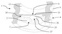
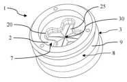
도 1은, 제1의 전반적인 실시형태에 따른, 본 발명에 따른 밸브 스토퍼의 전반적인 사시도이다.
도 2는 도 1의 밸브 스토퍼의 전반적인 단면도이다.
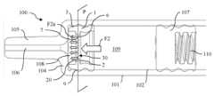
도 3a는, 제1 조성물 주입 전의, 제1 조성물 및 제2 조성물을 분리하는 밸브 스토퍼를 포함하는 의료용 주입 장치의 단면도이다.
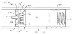
도 3b는, 제1 조성물의 주입의 종료 시의, 도 3a의 의료용 주입 장치의 단면도이다.
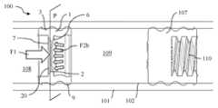
도 3c는, 제2 조성물의 주입 중의, 도 3a의 의료용 주입 장치의 단면도이다.
도 3d는, 밸브 스토퍼가 압궤 위치에 있는, 제2 조성물의 주입의 종료 시의, 도 3a의 의료용 주입 장치의 단면도이다.
도 3e는, 개방된, 체크 밸브의 기능을 도시하는, 분할부를 포함하는 평면 내의, 제1의 전반적인 실시형태에 따른 밸브 스토퍼의 횡단면도이다.
도 3f는, 폐쇄된, 체크 밸브의 기능을 도시하는, 제1의 전반적인 실시형태에 따른 밸브 스토퍼의 도면이다.
도 4는, 제2의 전반적인 실시형태의 제1 실시형태에 따른, 본 발명의 밸브 스토퍼의 전반적인 사시도이다.
도 5는 도 4의 밸브 스토퍼의 원위 면의 도면이다.
도 6은 도 4의 밸브 스토퍼의 전반적인 단면도이다.
도 7은 도 4의 밸브 스토퍼의 전반적인 측면 단면도이다.
도 8은, 제2의 전반적인 실시형태의 제2 실시형태에 따른, 본 발명의 밸브 스토퍼의 전반적인 사시도이다.
도 9는 도 8의 밸브 스토퍼의 원위 면의 도면이다.
도 10은 도 8의 밸브 스토퍼의 전반적인 단면도이다.
도 11은 도 8의 밸브 스토퍼의 전반적인 측면 단면도이다.
도 12a는, 밸브 스토퍼의 멤브레인을 통한 유체 경로의 생성을 도시하는, 노치를 포함하는 평면 내의, 제2의 전반적인 실시형태의 제1 실시형태에 따른 밸브 스토퍼의 횡단면도이다.
도 12b는, 유체 경로가 폐쇄된, 제2의 전반적인 실시형태의 제1 실시형태에 따른, 밸브 스토퍼의 횡단면도이다.
도 13a는, 밸브 스토퍼의 멤브레인을 통한 유체 경로의 생성을 도시하는, 노치를 포함하는 평면 내의, 제2의 전반적인 실시형태의 제2 실시형태에 따른 밸브 스토퍼의 횡단면도이다.
도 13b는, 유체 경로가 폐쇄된, 제2의 전반적인 실시형태의 제2 실시형태에 따른, 밸브 스토퍼의 횡단면도이다.
도 14는, 유체 경로가 멤브레인을 통해서 개방된, 제2의 전반적인 실시형태의 제1 실시형태에 따른, 밸브 스토퍼의 전반적인 사시도이다.
도 15는, 유체 경로가 멤브레인을 통해서 개방된, 제2의 전반적인 실시형태의 제2 실시형태에 따른, 밸브 스토퍼의 전반적인 사시도이다.
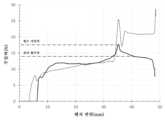
도 16은, 벤치(bench)의 변위의 관점에서, 본 발명에 따른 밸브 스토퍼에 그리고 종래 기술로부터 알려진 스토퍼에 가해지는 힘의 전개를 도시하는 그래프이다.
도 17은, 알려진 스토퍼 및 본 발명에 따른 밸브 스토퍼에 대한, 밸브 개방력으로 지칭되는, 밸브를 개방하는데 필요한 힘을 도시하는 그래프이다.
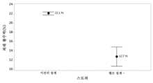
도 18은 본 발명에 따른 밸브 스토퍼 및 종래 기술로부터 알려진 스토퍼의 최대 활주력을 도시하는 그래프이다.Additional features and advantages of the present invention will become apparent from the following detailed description taken in conjunction with the accompanying drawings.
FIG. 1 is a general perspective view of a valve stopper according to the present invention, according to a first general embodiment.
Figure 2 is a general cross-sectional view of the valve stopper of Figure 1.
FIG. 3A is a cross-sectional view of a medical infusion device including a valve stopper for separating a first composition and a second composition prior to injection of the first composition.
FIG. 3b is a cross-sectional view of the medical infusion device of FIG. 3a at the end of injection of the first composition.
FIG. 3c is a cross-sectional view of the medical infusion device of FIG. 3a during injection of the second composition.
FIG. 3d is a cross-sectional view of the medical infusion device of FIG. 3a at the end of injection of the second composition, with the valve stopper in the collapsed position.
FIG. 3e is a cross-sectional view of a valve stopper according to a first general embodiment, within a plane including a split section, illustrating the function of an open check valve.
FIG. 3f is a drawing of a valve stopper according to a first general embodiment, illustrating the function of a closed check valve.
FIG. 4 is a general perspective view of a valve stopper of the present invention according to the first embodiment of the second general embodiment.
Figure 5 is a drawing of the distal surface of the valve stopper of Figure 4.
Figure 6 is a general cross-sectional view of the valve stopper of Figure 4.
Figure 7 is a general side cross-sectional view of the valve stopper of Figure 4.
FIG. 8 is a general perspective view of a valve stopper of the present invention according to a second embodiment of the second general embodiment.
Figure 9 is a drawing of the distal surface of the valve stopper of Figure 8.
Fig. 10 is a general cross-sectional view of the valve stopper of Fig. 8.
Figure 11 is a general side cross-sectional view of the valve stopper of Figure 8.
FIG. 12a is a cross-sectional view of a valve stopper according to a first embodiment of the second overall embodiment, in a plane including a notch, illustrating the creation of a fluid path through the membrane of the valve stopper.
FIG. 12b is a cross-sectional view of a valve stopper according to a first embodiment of the second overall embodiment, with the fluid path closed.
FIG. 13a is a cross-sectional view of a valve stopper according to a second embodiment of the second overall embodiment, in a plane including a notch, illustrating the creation of a fluid path through the membrane of the valve stopper.
FIG. 13b is a cross-sectional view of a valve stopper according to a second embodiment of the second overall embodiment, wherein the fluid path is closed.
FIG. 14 is a general perspective view of a valve stopper according to a first embodiment of the second general embodiment, wherein the fluid path is opened through a membrane.
FIG. 15 is a general perspective view of a valve stopper according to a second embodiment of the second general embodiment, wherein the fluid path is opened through a membrane.
Fig. 16 is a graph showing the development of a force applied to a valve stopper according to the present invention and to a stopper known from the prior art, from the viewpoint of displacement of the bench.
FIG. 17 is a graph showing the force required to open a valve, referred to as valve opening force, for a known stopper and a valve stopper according to the present invention.
Figure 18 is a graph showing the maximum sliding force of a valve stopper according to the present invention and a stopper known from the prior art.
본 발명은, 적어도 하나의 조성물을 주입하기 위한, 바람직하게 적어도 2개의 조성물을 순차적으로 주입하기 위한 주입 장치(100)의 몸통(101)의 내측에 배치되도록 구성된 밸브 스토퍼(1)에 관한 것이다. 그러한 주입 장치(100)는, 건강 관리 전문가에 의해서 환자에게 또는 자가-주입의 경우에 환자 자신에 의해서, 약제 조성물의 주입을 수행하기에 특히 적합하다.The present invention relates to a valve stopper (1) configured to be arranged inside a body (101) of an injection device (100) for injecting at least one composition, preferably for sequentially injecting at least two compositions. Such an injection device (100) is particularly suitable for performing an injection of a pharmaceutical composition into a patient by a health care professional or, in case of self-injection, by the patient himself.
조성물은 유체이고, 약제 약물, 백신 등과 같은 액체일 수 있다. 몸통이 상기 조성물로 충진될 때, 공기, 질소, 또는 다른 가스 또는 이들의 혼합물과 같은 가스가 (작은 기포 형태로) 상기 몸통 내에 존재할 수 있다.The composition is a fluid, and may be a liquid, such as a pharmaceutical drug, a vaccine, etc. When the body is filled with said composition, a gas, such as air, nitrogen, or another gas or a mixture thereof, may be present within the body (in the form of small bubbles).
본 발명에 따른 밸브 스토퍼(1)의 제1의 전반적인 실시형태가 도 1에서 전반적인 도면으로서 그리고 도 2에서 단면도로서 도시되어 있다.A first general embodiment of a valve stopper (1) according to the present invention is illustrated as a general drawing in Fig. 1 and as a cross-sectional view in Fig. 2.
밸브 스토퍼(1)는, 상기 밸브 스토퍼가 내부에 삽입되도록 의도된, 주사기와 같은, 주입 장치의 몸통(101)의 형상에 상응하는, 실질적으로 원통형 형상을 갖는다.The valve stopper (1) has a substantially cylindrical shape corresponding to the shape of the body (101) of an injection device, such as a syringe, into which the valve stopper is intended to be inserted.
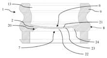
밸브 스토퍼(1)는 멤브레인(2)을 포함하고, 멤브레인은 근위 면(6) 및 원위 면(7)을 포함한다. 밸브 스토퍼의 측방향 벽(3)이 멤브레인으로부터 원위적으로, 또는 원위적 및 근위적 모두로 연장된다.The valve stopper (1) comprises a membrane (2), the membrane comprising a proximal face (6) and a distal face (7). A lateral wall (3) of the valve stopper extends distally from the membrane, or both distally and proximally.
측방향 벽(3)은 공동(4)을 형성하고, 공동은 측방향 벽의 내부 면(5) 및 멤브레인의 근위 면(6) 또는 원위 면(7)에 의해서 경계 한정되는 중공형 부피이다.The lateral wall (3) forms a cavity (4), which is a hollow volume bounded by the inner surface (5) of the lateral wall and the proximal surface (6) or distal surface (7) of the membrane.
도 1 및 도 2에 도시된 실시형태에서, 측방향 벽(3)은 원위 방향으로만 연장되고, 공동(4)은 측방향 벽의 내부 면(5)과, 공동의 하단부를 구성하는 멤브레인의 근위 면(6)에 의해서 경계 한정된다.In the embodiment shown in FIGS. 1 and 2, the lateral wall (3) extends only in the distal direction, and the cavity (4) is bounded by the inner surface (5) of the lateral wall and the proximal surface (6) of the membrane forming the lower portion of the cavity.
다른 실시형태(미도시)에 따라, 밸브 스토퍼의 측방향 벽(3)은 멤브레인(2)으로부터 근위적 및 원위적 모두로 연장된다. 그에 의해서, 멤브레인은, 측방향 벽의 내부 면(5) 및 멤브레인의 근위 면(6)에 의해서 경계 한정되는 근위 공동, 및 측방향 벽의 내부 면(5) 및 멤브레인의 원위 면(7)에 의해서 경계 한정되는 원위 공동을 포함하는, 2개의 각각의 공동들을 분리한다.According to another embodiment (not shown), the lateral wall (3) of the valve stopper extends both proximally and distally from the membrane (2). Thereby, the membrane separates two respective cavities, comprising a proximal cavity, which is bounded by the inner face (5) of the lateral wall and the proximal face (6) of the membrane, and a distal cavity, which is bounded by the inner face (5) of the lateral wall and the distal face (7) of the membrane.
측방향 벽(3)은 유리하게, 몸통의 내부 벽과 밀봉 가능하게 결합되도록 구성된 외부 밀봉 표면(8)을 구비한다.The lateral wall (3) advantageously has an external sealing surface (8) configured to sealably join the inner wall of the body.
밀봉 표면(8)은 연속적이고, 이는 밀봉 표면이 밸브 스토퍼의 원주를 따라서 연속적으로 연장되어 링을 형성한다는 것을 의미한다. 연속적인 표면이 밸브 스토퍼(1)의 측방향 벽의 외부 면과 의료용 컨테이너의 몸통의 내부 표면(102) 사이에서 연장되기 때문에, 밸브 스토퍼(1)와 몸통(101) 사이의 조성물의 임의의 통로가 방지된다. 그에 따라, 최적의 밀봉이 보장된다.The sealing surface (8) is continuous, which means that the sealing surface extends continuously along the circumference of the valve stopper to form a ring. Since the continuous surface extends between the outer surface of the lateral wall of the valve stopper (1) and the inner surface (102) of the body of the medical container, any passage of the composition between the valve stopper (1) and the body (101) is prevented. Accordingly, an optimal sealing is ensured.
바람직한 실시형태에 따라, 밀봉 표면(8)은 둘 이상의 밀봉 리브(9)를 포함할 수 있다. 밸브 스토퍼 및 몸통의 치수에 따라 밀봉을 추가적으로 최적화하도록, 리브의 수뿐만 아니라, 높이, 폭, 및 2개의 인접한 리브들 사이의 거리와 같은, 각각의 리브의 치수가 구성될 수 있다.According to a preferred embodiment, the sealing surface (8) may comprise two or more sealing ribs (9). In order to further optimize the sealing depending on the dimensions of the valve stopper and the body, not only the number of ribs but also the dimensions of each rib, such as the height, width and the distance between two adjacent ribs, can be configured.
실시형태(미도시)에 따라, 밸브 스토퍼(1)는, 중간 리브 및 2개의 측방향 리브를 포함하는, 3개의 리브(9)를 포함하고, 멤브레인은 중간 리브와 정렬된다. 이러한 실시형태에서, 밸브 스토퍼의 측방향 벽(3)은 멤브레인으로부터 근위적 및 원위적 모두로 연장되고, 2개의 공동을 경계 한정한다. 2개의 측방향 리브들은 2개의 공동 중 하나와 각각 정렬된다. 다른 실시형태(미도시)에 따라, 밸브 스토퍼의 측방향 벽(3)은 주로 멤브레인으로부터 근위적으로 연장되고, 측방향 벽의 작은 부분이 멤브레인으로부터 돌출되고 원위적으로 연장된다. 이러한 실시형태에서, 밸브 스토퍼(1)와 몸통의 원위 단부 사이에 포함된 조성물 내에 존재하는 가스 기포의 수가 감소될 수 있다.According to an embodiment (not shown), the valve stopper (1) comprises three ribs (9), including a middle rib and two lateral ribs, the membrane being aligned with the middle rib. In this embodiment, the lateral wall (3) of the valve stopper extends both proximally and distally from the membrane and delimits two cavities. The two lateral ribs are each aligned with one of the two cavities. According to another embodiment (not shown), the lateral wall (3) of the valve stopper extends mainly proximally from the membrane, with a small part of the lateral wall protruding from the membrane and extending distally. In this embodiment, the number of gas bubbles present in the composition comprised between the valve stopper (1) and the distal end of the body can be reduced.
둘 이상의 리브의 존재는, 밸브 스토퍼의 평면 측방향 벽에 비해서, 밸브 스토퍼의 측방향 벽과 주입 장치의 몸통의 내부 표면 사이의 접촉 표면을 감소시키고, 그에 따라 밸브 스토퍼의 활주 성능을 몸통에 비해서 개선한다. 결과적으로, 밸브 스토퍼를 몸통 내측에서 변위시키기 위해서 밸브 스토퍼에 가해질 필요가 있는 힘이 감소되고, 이는 사용자가 더 용이하게 주입할 수 있게 하며, 그리고 일반적으로 몸통에 대한 밸브 스토퍼의 미끄러짐으로부터 초래되는 슬립-스틱 효과(slip-stick effect)를 방지한다. 그 이외에, 리브들 사이의 거리가 멀어질 수록, 밸브 스토퍼의 안정성이 커진다.The presence of two or more ribs reduces the contact surface between the lateral wall of the valve stopper and the inner surface of the body of the injection device, compared to the flat lateral wall of the valve stopper, and thus improves the gliding performance of the valve stopper compared to the body. As a result, the force required to be applied to the valve stopper to displace it from the inside of the body is reduced, which makes it easier for the user to inject, and generally prevents the slip-stick effect resulting from slipping of the valve stopper relative to the body. In addition, the greater the distance between the ribs, the greater the stability of the valve stopper.
멤브레인의 근위 면(6)은 오목한 형상을 나타낸다.The proximal surface (6) of the membrane exhibits a concave shape.
멤브레인의 원위 면(7)은 평면형 또는 볼록한 형상을 나타낸다.The distal surface (7) of the membrane exhibits a flat or convex shape.
멤브레인의 면과 관련된 "오목"이라는 용어는, 상기 면이 곡선형이고 곡률의 정점이 도 3e의 평면(P)을 향해서 지향된다는 것을 의미하고, 평면(P)은, 원위-근위 방향에 수직이고 멤브레인의 가장 얇은 영역 내에서 그 두께의 중간을 포함하는 평면이다. 역으로, 멤브레인의 면과 관련된 "볼록"이라는 용어는, 상기 면이 곡선형이고 곡률의 정점이 평면(P)으로부터 멀리 연장된다는 것을 의미한다.The term "concave" with respect to a face of a membrane means that the face is curved and the vertex of the curvature is directed toward the plane (P) of FIG. 3e, the plane (P) being a plane that is perpendicular to the distal-proximal direction and includes the middle of the thickness within the thinnest region of the membrane. Conversely, the term "convex" with respect to a face of a membrane means that the face is curved and the vertex of the curvature extends away from the plane (P).
따라서, 오목한 형상을 나타내는, 멤브레인의 근위 면의 곡률의 정점은 멤브레인의 원위 면을 향해서 연장된다. 멤브레인의 원위 면이 볼록한 형상을 나타내는 경우에, 상기 원위 면의 곡률의 정점은 멤브레인의 근위 면으로부터 멀리 연장된다.Therefore, the vertex of the curvature of the proximal face of the membrane, which exhibits a concave shape, extends toward the distal face of the membrane. In the case where the distal face of the membrane exhibits a convex shape, the vertex of the curvature of the distal face extends away from the proximal face of the membrane.
멤브레인(2)은 노치를 포함한다. 상기 노치는 멤브레인(2)의 근위 면(6)과 원위 면(7) 사이에서 멤브레인의 두께의 적어도 일부를 통해서 연장된다. 노치는, 멤브레인(2)의 근위 면(6)으로부터 원위 면(7)까지 멤브레인(2)을 통해서 유체 경로(30)를 생성하도록 구성된다. 제1의 전반적인 실시형태에 따라, 노치는, 근위 면(6)과 원위 면(7) 사이에서 멤브레인을 통해서 연장되는 분할부(10)이다. 분할부(10)는, 조성물에 의해서 멤브레인의 근위 면(6)에 가해지는 압력에 따라, 공동(4)을 개방 또는 폐쇄하도록 구성되는 밸브를 형성한다.The membrane (2) comprises a notch. The notch extends through at least a portion of the thickness of the membrane between a proximal face (6) and a distal face (7) of the membrane (2). The notch is configured to create a fluid path (30) through the membrane (2) from the proximal face (6) to the distal face (7) of the membrane (2). According to a first general embodiment, the notch is a partition (10) extending through the membrane between the proximal face (6) and the distal face (7). The partition (10) forms a valve configured to open or close the cavity (4) depending on a pressure applied by the composition to the proximal face (6) of the membrane.
밸브 스토퍼는, 의료용 주입 장치를 위한 스토퍼를 제조하기 위해서 일반적으로 이용되는 탄성중합체 특성을 갖는 임의의 재료로 제조될 수 있다. 예를 들어, 밸브 스토퍼는 탄성중합체, 고무, 열가소성 탄성중합체, 및 액체 규소 고무로 제조될 수 있다.The valve stopper can be made of any material having elastomeric properties commonly used to manufacture stoppers for medical infusion devices. For example, the valve stopper can be made of an elastomer, a rubber, a thermoplastic elastomer, and a liquid silicone rubber.
분할부(10)는 바람직하게, 멤브레인의 근위 면의 중심을 통과하는 라인(11), 바람직하게 직선형 라인의 형태이다. 그러한 라인은 제조가 매우 단순하다. 멤브레인은 어떠한 분할부도 없이 제조될 수 있고, 이어서 분할부의 형성을 위해서 천공될 수 있다. 대안적으로, 분할부는 멤브레인의 제조 중에 멤브레인 내에 직접 형성될 수 있다.The dividing portion (10) is preferably in the form of a line (11), preferably a straight line, passing through the center of the proximal face of the membrane. Such a line is very simple to manufacture. The membrane can be manufactured without any dividing portion and then perforated to form the dividing portion. Alternatively, the dividing portion can be formed directly in the membrane during its manufacture.
분할부(11)의 길이는 바람직하게, 공동의 직경의 1/4 초과 및 공동(4)의 직경 미만이다. 공동의 직경의 1/4 미만의 길이는 밸브 개방을 위해서 사용자로부터 매우 큰 힘을 요구할 수 있고, 그에 의해서 주입 실행을 더 어렵게 만들 수 있다. 대조적으로, 공동의 직경을 초과하는 길이는, 공동으로 이어지지 않는 분할부의 부분을 쓸모 없게 만들 수 있고 분할부의 기능을 저하시킬 수 있다.The length of the split portion (11) is preferably greater than 1/4 of the diameter of the cavity and less than the diameter of the cavity (4). A length less than 1/4 of the diameter of the cavity may require too much force from the user to open the valve, thereby making the injection operation more difficult. In contrast, a length greater than the diameter of the cavity may render useless the portion of the split portion that does not lead to the cavity, thereby impairing the functionality of the split portion.
실시형태에 따라, 분할부(10)는 2개의 세그먼트(12)를 더 포함하고, 각각의 세그먼트는 라인(11)의 단부의 양 측면 상에서 연장되고, 그에 의해서 머리글자 "i"를 형성한다. 이러한 실시형태는 분할부의 더 큰 개방을 달성한다. 도 1에서, 2개의 세그먼트(12)는 분할부의 라인(11)에 실질적으로 수직이고, 바람직하게 멤브레인의 곡률에 매칭되도록 약간 곡선화되며, 이는 분할부(10)의 개방을 촉진한다.According to an embodiment, the splitter (10) further comprises two segments (12), each of which extends on either side of the end of the line (11), thereby forming the initial "i". This embodiment achieves a greater opening of the splitter. In Fig. 1, the two segments (12) are substantially perpendicular to the line (11) of the splitter and are preferably slightly curved to match the curvature of the membrane, which facilitates the opening of the splitter (10).
유리하게, 밸브 스토퍼의 멤브레인(2)은, 0.3 mm 내지 1 mm의 두께를 갖는다. 바람직하게, 밸브 스토퍼는 1 mL 내지 3 mL의 주입 부피를 갖는 주입 장치에서 이용되고, 여기에서 멤브레인(2)의 두께는 0.4 mm 내지 0.8 mm이고, 바람직하게 멤브레인(2)의 두께는 0.5 mm 이상, 바람직하게 0.6 mm 이상이다.Advantageously, the membrane (2) of the valve stopper has a thickness of 0.3 mm to 1 mm. Preferably, the valve stopper is used in an injection device having an injection volume of 1 mL to 3 mL, wherein the thickness of the membrane (2) is 0.4 mm to 0.8 mm, preferably the thickness of the membrane (2) is 0.5 mm or more, preferably 0.6 mm or more.
멤브레인(2)은 일-방향 멤브레인이고, 이는, 상기 조성물이 주입 방향을 의미하는 원위 방향으로 유동할 때에만, 조성물이 개방된 분할부(10)를 경유하여 멤브레인을 통과할 수 있게 허용하도록 멤브레인이 구성된다는 것을 의미한다. 달리 말해서, 분할부는, 단지, 조성물이 멤브레인의 근위 면(6)과 접촉되는 밸브 스토퍼의 일 측면으로부터 조성물이 멤브레인의 원위 면(7)과 접촉되는 밸브 스토퍼의 다른 측면으로, 조성물이 멤브레인을 통과할 수 있게 개방되도록 구성된다. 분할부(10)는, 조성물이 멤브레인의 원위 면(7)과 접촉되는 밸브 스토퍼의 다른 측면으로부터 조성물이 멤브레인의 근위 면(6)과 접촉되는 밸브 스토퍼의 일 측면으로, 즉 주입 방향에 반대되는 방향인 근위 방향으로, 조성물이 멤브레인을 통과하는 것을 방지하기 위해서 폐쇄되어 유지되도록 구성된다. 그러한 밸브는 "체크 밸브"로 지칭된다.The membrane (2) is a unidirectional membrane, which means that the membrane is configured such that the composition can pass through the membrane via the open splitter (10) only when the composition flows in the distal direction, meaning the injection direction. In other words, the splitter is configured such that it is open only to allow the composition to pass through the membrane from one side of the valve stopper where the composition is in contact with the proximal face (6) of the membrane to the other side of the valve stopper where the composition is in contact with the distal face (7) of the membrane. The splitter (10) is configured such that it remains closed to prevent the composition from passing through the membrane from the other side of the valve stopper where the composition is in contact with the distal face (7) of the membrane to one side of the valve stopper where the composition is in contact with the proximal face (6) of the membrane, i.e. in the proximal direction, opposite to the injection direction. Such a valve is referred to as a "check valve".
분할부(10)는, 분할부를 개방하기 위해서 멤브레인의 근위 면에 가해야 할 필요가 있는 힘에 상응하는, 밸브 개방력(Fop)을 나타낸다. 그에 따라, 밸브 개방력은 분할부의 개방 문턱값에 상응한다. 밸브 개방력은 바람직하게 10 N 내지 25 N, 바람직하게 10N 내지 20N, 더 바람직하게 15 N 내지 20 N이다. 분할부(10)는, 멤브레인의 근위 면(6)에 가해지는 압력(P2)이 Fop 보다 작은 한 폐쇄되어 유지되도록, 그리고 상기 압력(P2)이 Fop 이상일 때 개방되도록, 그에 의해서 초기에 밸브 스토퍼에 대해서 근위적으로 위치된 조성물의 주입을 허용하도록 구성된다.The divider (10) exhibits a valve opening force (Fop ) corresponding to the force which has to be applied to the proximal face of the membrane in order to open the divider. Accordingly, the valve opening force corresponds to the opening threshold of the divider. The valve opening force is preferably 10 N to 25 N, preferably 10 N to 20 N, more preferably 15 N to 20 N. The divider (10) is configured so as to remain closed as long as the pressure (P2) applied to the proximal face (6) of the membrane is less than Fop , and to open when the pressure (P2) is greater than Fop , thereby allowing the injection of the composition which is initially positioned proximally relative to the valve stopper.
멤브레인의 근위 면의 오목한 형상은 밸브 개방력(Fop)을 최소화하고, 그에 의해서 밸브의 개방 및 밸브 스토퍼에 대해서 근위적으로 위치된 조성물의 후속 주입을 촉진하는 한편, 밸브가 체크 밸브로서 기능할 수 있게 한다.The concave shape of the proximal face of the membrane minimizes the valve opening force (Fop ), thereby facilitating opening of the valve and subsequent injection of a composition positioned proximally relative to the valve stopper, while allowing the valve to function as a check valve.
본 발명자의 계산에 따라, 멤브레인의 오목 면의 곡률 반경은 바람직하게 주사기의 몸통의 내경보다 약 1.8배 내지 ±30% 더 크다(즉, 1.2배 내지 2.3배 더 크다). 근위 면의 곡률 반경과 몸통의 내경 사이의 이러한 비율은, 주입을 위해서 밸브를 개방하는데 필요한 힘을 제한하기 위해서 최적화된다.According to the inventors' calculations, the radius of curvature of the concave surface of the membrane is preferably about 1.8 to ±30% larger than the inner diameter of the body of the syringe (i.e., 1.2 to 2.3 times larger). This ratio between the radius of curvature of the proximal surface and the inner diameter of the body is optimized to limit the force required to open the valve for injection.
분할부의 형상은 제2 액체의 주입력에 영향을 미친다. 분할부가 작을수록, 주입력은 더 커진다.The shape of the split section affects the injection force of the second liquid. The smaller the split section, the greater the injection force.
밸브 스토퍼의 측방향 벽(3)은 유리하게, 원위 방향으로 가해지는 기계적 압력 하에서 밸브 스토퍼(1)의 압궤를 유도하도록 구성되는 내부 함몰부(13)를 포함한다.The lateral wall (3) of the valve stopper advantageously comprises an internal recess (13) configured to induce collapse of the valve stopper (1) under a mechanical pressure applied in the distal direction.
도 2의 실시형태에서, 적어도 하나의 함몰부(13)는, 밸브 스토퍼의 원주를 따라서 측방향 벽(3) 내에서 연장되는 환형 홈이다. 바람직하게, 함몰부(13) 만이 측방향 벽(3) 내에서 연장된다. 환형 홈은 바람직하게 리브(9)와 정렬되고, 더 바람직하게 리브들의 수가 홀수일 때 중간 리브와 정렬된다.In the embodiment of FIG. 2, at least one recess (13) is an annular groove extending within the lateral wall (3) along the circumference of the valve stopper. Preferably, only the recess (13) extends within the lateral wall (3). The annular groove is preferably aligned with the rib (9), more preferably with the middle rib when the number of ribs is odd.
내부 함몰부(13)의 존재는, 스토퍼의 압궤를 가능하게 하고, 그에 따라 사부피를 감소시키며, 그러한 사부피는, 조성물의 주입 후에 밸브 스토퍼와 접촉되고 그에 대해서 원위적으로 몸통(101) 내측에서 잔류하는 조성물의 부피에 상응한다. 이는, 주입되는 조성물의 총 부피를 증가시킬 수 있게 하고, 조성물의 폐기를 방지한다.The presence of the internal recess (13) allows for the collapse of the stopper and thus reduces the dead volume, which corresponds to the volume of the composition that comes into contact with the valve stopper after injection of the composition and remains distally relative thereto inside the body (101). This allows for an increase in the total volume of the composition injected and prevents waste of the composition.
본 발명에 따른 밸브 스토퍼(1)의 제2의 전반적인 실시형태가 도 4 내지 도 11 그리고 도 14 및 도 15에 도시되어 있고, 도 4 내지 도 7 및 도 14는 밸브 스토퍼의 제1 실시형태에 관한 것이고, 도 8 내지 도 11 및 도 15는 밸브 스토퍼의 제2 실시형태에 관한 것이다.A second overall embodiment of a valve stopper (1) according to the present invention is illustrated in FIGS. 4 to 11 and FIGS. 14 and 15, wherein FIGS. 4 to 7 and FIG. 14 relate to a first embodiment of the valve stopper, and FIGS. 8 to 11 and FIG. 15 relate to a second embodiment of the valve stopper.
제2의 전반적인 실시형태의 밸브 스토퍼의 전반적인 구조는 전술한 제1의 전반적인 실시형태의 구조와 유사하고, 추가적으로 설명하지는 않을 것이다. 도 1 내지 도 3 및 도 4 내지 도 11에서 제공된 제1 및 제2의 전반적인 실시형태 사이의 공통되는 특징은 동일한 참조 번호를 갖는다.The overall structure of the valve stopper of the second overall embodiment is similar to the structure of the first overall embodiment described above and will not be described further. Common features between the first and second overall embodiments provided in FIGS. 1 to 3 and FIGS. 4 to 11 have the same reference numerals.
제1의 전반적인 실시형태보다 우수한 제2의 전반적인 실시형태의 장점은, 밸브 스토퍼의 제조 프로세스 중에 멤브레인이 그 구조적 무결성을 유지한다는 것이고, 이는, 특히 진공과 관련된 단계들이 수행될 때, 상기 프로세스가 보다 용이하게 실행될 수 있게 한다.An advantage of the second overall embodiment over the first overall embodiment is that the membrane maintains its structural integrity during the manufacturing process of the valve stopper, which makes the process more easily executable, especially when steps involving vacuum are performed.
제2의 전반적인 실시형태에 따라, 노치(20)는 멤브레인(2)의 두께의 일부에서만 연장된다. 파열 부분으로 지칭되는, 노치가 횡단하지 않는 멤브레인의 두께의 부분(21)은, 조성물에 의해서 가해지는 결정된 압력 하에서 노치를 따라서 파열되도록, 그에 따라 근위 면(6)으로부터 원위 면(7)까지 멤브레인(2)을 통해서 유체 경로(30)를 생성하도록 구성된다.According to a second general embodiment, the notch (20) extends only through a portion of the thickness of the membrane (2). A portion (21) of the membrane thickness that is not traversed by the notch, referred to as the rupture portion, is configured to rupture along the notch under a determined pressure applied by the composition, thereby creating a fluid path (30) through the membrane (2) from the proximal face (6) to the distal face (7).
이를 위해서, 노치(20)는 멤브레인(2) 내에서 국소적으로 취약화된 구역을 형성하고, 그러한 구역은, 결정된 압력이 주입되는 조성물에 의해서 근위 면 중 하나 상에 인가될 때, 멤브레인이 파열되게 한다. 파열될 때, 파열 부분(21)은 또한, 그렇게 형성된 유체 경로를 따른 조성물의 유동을 위한 안내부로서의 작용을 한다.To this end, the notch (20) forms a locally weakened zone within the membrane (2), which causes the membrane to rupture when a determined pressure is applied to one of the proximal faces by the composition being injected. Upon rupture, the ruptured portion (21) also acts as a guide for the flow of the composition along the fluid path thus formed.
파열 부분(21)은, 조성물에 의해서 멤브레인(2)의 근위 면(6)에 가해지는 압력에 따라, 공동(4)을 개방 또는 폐쇄하도록 구성되는 밸브를 형성한다.The rupture portion (21) forms a valve configured to open or close the cavity (4) depending on the pressure applied to the proximal face (6) of the membrane (2) by the composition.
노치(20)는 바람직하게 멤브레인의 원위 면(7)으로부터 멤브레인(2)의 일부를 통해서 연장된다. 노치는 대안적으로 멤브레인의 근위 면(6)으로부터 연장될 수 있다.The notch (20) preferably extends through a portion of the membrane (2) from the distal face (7) of the membrane. The notch may alternatively extend from the proximal face (6) of the membrane.
바람직하게, 밸브 스토퍼는 1 mL 내지 3 mL의 주입 부피를 갖는 주입 장치에서 이용되고, 여기에서 멤브레인(2)의 두께는 0.4 mm 내지 0.8 mm이고, 바람직하게 멤브레인(2)의 두께는 0.5 mm 이상, 더 바람직하게 0.6 mm 이상이다.Preferably, the valve stopper is used in an injection device having an injection volume of 1 mL to 3 mL, wherein the thickness of the membrane (2) is 0.4 mm to 0.8 mm, preferably the thickness of the membrane (2) is 0.5 mm or more, more preferably 0.6 mm or more.
노치(20)의 깊이는 바람직하게 멤브레인의 두께의 약 25% 내지 50%, 더 바람직하게 멤브레인의 두께의 25% 내지 35%이다. 약 0.5 mm의 두께를 가지는 멤브레인에서, 노치(20)의 깊이는 바람직하게 0.1 mm 이상, 더 바람직하게 0.2 mm 이상이다. 이는, 상기 멤브레인을 파열하는데 필요한, 조성물에 의해서 가해지는 압력을 낮추는 것에 의해서, 멤브레인의 파열을 촉진한다.The depth of the notch (20) is preferably about 25% to 50% of the thickness of the membrane, more preferably about 25% to 35% of the thickness of the membrane. In a membrane having a thickness of about 0.5 mm, the depth of the notch (20) is preferably 0.1 mm or more, more preferably 0.2 mm or more. This promotes rupture of the membrane by lowering the pressure applied by the composition required to rupture the membrane.
제1의 전반적인 실시형태와 유사하게, 제2의 전반적인 실시형태에 따른 멤브레인(2)은, 상기 조성물이 주입 방향을 의미하는 원위 방향으로 유동할 때에만, 조성물이 노치(20)를 경유하여 멤브레인을 통과할 수 있게 허용하도록 구성되는 일-방향 멤브레인이다. 달리 말해서, 파열 부분(21)은, 단지, 조성물이 멤브레인의 근위 면(6)과 접촉되는 밸브 스토퍼의 일 측면으로부터 조성물이 멤브레인의 원위 면(7)과 접촉되는 밸브 스토퍼의 다른 측면으로, 조성물이 멤브레인을 통과할 수 있게 개방되도록 구성된다. 그에 의해서, 멤브레인의 파열 부분(21)은 체크 밸브로서 작용하도록 구성된다.Similarly to the first general embodiment, the membrane (2) according to the second general embodiment is a one-way membrane which is configured to allow the composition to pass through the membrane via the notch (20) only when the composition flows in the distal direction, meaning the injection direction. In other words, the rupture portion (21) is configured to open only to allow the composition to pass through the membrane from one side of the valve stopper where the composition comes into contact with the proximal face (6) of the membrane to the other side of the valve stopper where the composition comes into contact with the distal face (7) of the membrane. Thereby, the rupture portion (21) of the membrane is configured to act as a check valve.
파열 부분(21)은, 멤브레인의 근위 면(6)에 가해지는 압력(P2)이 밸브 개방력(Fop)보다 작은 한 폐쇄되어 유지되도록, 그리고 상기 압력(P2)이 Fop 이상일 때 개방되도록, 그에 의해서 멤브레인을 통해서 유체 경로를 생성하고 초기에 밸브 스토퍼에 대해서 근위적으로 위치된 조성물의 주입을 허용하도록 구성된다.The rupture portion (21) is configured to remain closed as long as the pressure (P2) applied to the proximal face (6) of the membrane is less than the valve opening force (Fop ), and to open when the pressure (P2) is greater than or equal to Fop , thereby creating a fluid path through the membrane and allowing injection of the composition initially positioned proximally with respect to the valve stopper.
도 4 내지 도 7에 도시된, 제2의 전반적인 실시형태의 제1 실시형태에 따라, 노치는 길다란 형태를 갖는다. 길다란 형태는, 공통 라인(23)에서 결합되는 2개의 대향된 경사 표면(22)을 포함한다. 2개의 대향된 경사 표면(22)은 2개의 원뿔형 단부(24)에 의해서 측방향으로 결합된다. 공통 라인은 멤브레인의 파열 부분(21)과 접촉되고, 파열의 시작 지점을 구성한다.According to a first embodiment of the second general embodiment, as illustrated in FIGS. 4 to 7, the notch has an elongated shape. The elongated shape comprises two opposed inclined surfaces (22) which are joined at a common line (23). The two opposed inclined surfaces (22) are joined laterally by two conical ends (24). The common line contacts the rupture portion (21) of the membrane and constitutes the starting point of the rupture.
따라서, 조성물에 의해서 멤브레인 상으로 가해지는 압력이 밸브 개방력(Fop)보다 클 때, 공통 라인(23)이 파열되고 멤브레인(2)의 파열 부분(21)의 파열을 유도한다. 이는, 멤브레인을 통한 유체 경로를 생성한다.Therefore, when the pressure applied to the membrane by the composition is greater than the valve opening force (Fop ), the common line (23) ruptures, inducing rupture of the ruptured portion (21) of the membrane (2). This creates a fluid path through the membrane.
2개의 경사 표면(22)의 경사 방향은, 노치가 연장되기 시작하는 멤브레인의 면에 따라 달라진다. 노치(20)가 멤브레인의 원위 면(7)으로부터 연장될 때, 경사 표면(22)은, 조성물의 주입 방향에 반대되는, 근위 방향을 향해서 지향된다. 역으로, 노치(20)가 멤브레인의 근위 면(6)으로부터 연장될 때, 경사 표면(22)은, 조성물의 주입 방향인, 원위 방향을 향해서 지향된다.The inclination direction of the two inclined surfaces (22) varies depending on the face of the membrane from which the notch begins to extend. When the notch (20) extends from the distal face (7) of the membrane, the inclined surface (22) is oriented in the proximal direction, opposite to the injection direction of the composition. Conversely, when the notch (20) extends from the proximal face (6) of the membrane, the inclined surface (22) is oriented in the distal direction, which is the injection direction of the composition.
상이한 구조적 변경들이 길다란 노치에 대해서 이루어질 수 있다. 예를 들어, 2개의 원뿔형 단부(24)가 서로 평행한 2개의 직선형 벽에 의해서 대체될 수 있다. 또한, 길다란 형상의 길이방향 측면들을 형성하는, 멤브레인의 근위 또는 원위 표면과 경사 표면의 교차부가 도 4 및 도 5에 도시된 바와 같이 서로를 향해서 약간 굽혀질 수 있거나, 직선형이고 서로 평행할 수 있다.Different structural modifications can be made to the elongated notch. For example, the two conical ends (24) can be replaced by two straight walls that are parallel to each other. Also, the intersection of the proximal or distal surface of the membrane and the inclined surface, which form the longitudinal sides of the elongated shape, can be slightly bent towards each other as shown in FIGS. 4 and 5, or can be straight and parallel to each other.
도 8 내지 도 11에 도시된, 제2의 전반적인 실시형태의 제2 실시형태에 따라, 노치(20)는 십자가 형태이다. 십자가는, 십자가의 중심에서 교차되는 2개의 수직 세그먼트(25)를 포함한다. 멤브레인은 바람직하게 십자가의 중심에서만 파열된다. 중심은, 선택적인, 중앙 십자가(26)로 지칭되는, 도 8 및 도 9의 미세 라인의 다른 십자가에 의해서 표시되어 있다. 중앙 십자가(26)는 멤브레인의 파열 부분(21)과 접촉되고, 파열의 시작 지점을 구성할 수 있다. 물론, 십자가(20)가 한번에 전체적으로 파열될 수 있고, 중앙 십자가(26)(존재할 때) 및 2개의 수직 세그먼트(25)가 실질적으로 동시에 파열된다.According to a second embodiment of the second overall embodiment, as illustrated in FIGS. 8 to 11 , the notch (20) is in the form of a cross. The cross comprises two vertical segments (25) which intersect in the center of the cross. The membrane is preferably ruptured only in the center of the cross. The center is indicated by another cross of the fine lines in FIGS. 8 and 9 , which is optionally referred to as the central cross (26). The central cross (26) contacts the rupture portion (21) of the membrane and can constitute the starting point of the rupture. Of course, the cross (20) can be ruptured entirely at once, with the central cross (26) (when present) and the two vertical segments (25) being ruptured substantially simultaneously.
따라서, 조성물에 의해서 멤브레인 상으로 가해지는 압력이 밸브 개방력(Fop)보다 클 때, 십자가(20)가 파열되고 멤브레인의 파열 부분(21)의 파열을 유도한다. 이는, 멤브레인을 통한 유체 경로를 생성한다. 바람직하게, 중앙 십자가(26)만이 파열되고, 중앙 십자가를 경계 한정하는 십자가의 돌출 부분(27)은 파열되지 않고, 중앙 십자가의 파열을 따르도록 그리고 그렇게 형성된 유체 경로를 따른 조성물의 유동을 안내하도록, 변형될 수 있다.Therefore, when the pressure applied to the membrane by the composition is greater than the valve opening force (Fop ), the cross (20) ruptures, inducing rupture of the ruptured portion (21) of the membrane. This creates a fluid path through the membrane. Preferably, only the central cross (26) ruptures, and the protruding portion (27) of the cross that delimits the central cross is not ruptured, but can be deformed to follow the rupture of the central cross and guide the flow of the composition along the fluid path thus formed.
길이, 폭, 및 깊이와 같은 노치(20)의 치수는, 제2 조성물을 주입하는데 필요한 주입력을 조정하도록 구성될 수 있다. 제2의 전반적인 실시형태의 제1 실시형태와 관련하여, 길다란 형상의 길이 및 폭, 경사 표면의 경사 각도가 그에 따라 구성될 수 있다. 제2의 전반적인 실시형태의 제2 실시형태와 관련하여, 십자가의 2개의 세그먼트의 길이 및 폭이 또한 그에 따라 조정될 수 있다.The dimensions of the notch (20), such as length, width, and depth, can be configured to adjust the injection force required to inject the second composition. With respect to the first embodiment of the second general embodiment, the length and width of the elongated shape and the inclination angle of the inclined surface can be configured accordingly. With respect to the second embodiment of the second general embodiment, the length and width of the two segments of the cross can also be adjusted accordingly.
본 발명의 밸브 스토퍼(1)는 적어도 하나의 조성물을 주입하기 위한, 그리고 바람직하게 적어도 2개의 조성물을 순차적으로 주입하기 위한 주입 장치(100)의 몸통(101)의 내측에 배치되도록 구성된다. 그러한 주입 장치의 실시형태가 도 3a에 도시되어 있다.The valve stopper (1) of the present invention is configured to be placed inside the body (101) of an injection device (100) for injecting at least one composition, and preferably for sequentially injecting at least two compositions. An embodiment of such an injection device is illustrated in Fig. 3a.
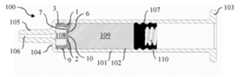
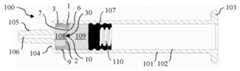
도 3a를 참조하면, 주입 장치(100)는, 근위 단부(103)로부터 원위 단부(104)까지 연장되는 몸통(101)을 포함하는 주사기이다. 원위 단부는, 조성물의 통과를 위한 채널(106)을 둘러싸는 선단부(105)를 구비한다.Referring to FIG. 3A, the injection device (100) is a syringe including a body (101) extending from a proximal end (103) to a distal end (104). The distal end has a tip (105) surrounding a channel (106) for passage of the composition.
주입 장치(100)는, 조성물을 주입하기 위해서 몸통의 내측에서 병진운동적으로 이동 가능하게 구성된 플런저 스토퍼(107)를 포함한다. 플런저 스토퍼는 유리하게, 주입을 수행하기 위해서 플런저 로드가 플런저 스토퍼를 원위 방향으로 밀 때 헤드를 수용하기 위해서 플런저 로드의 헤드의 형상에 상응하는 형상을 갖는, 중공형 부피(110)를 포함한다.The injection device (100) comprises a plunger stopper (107) configured to be translationally movable inside the body for injecting the composition. The plunger stopper advantageously comprises a hollow volume (110) having a shape corresponding to the shape of a head of the plunger rod for receiving the head when the plunger rod pushes the plunger stopper distally for performing the injection.
밸브 스토퍼(1)는 몸통의 원위 단부(104)와 플런저 스토퍼(107) 사이에 배열되고, 몸통(101) 내측에서 병진운동적으로 이동될 수 있다. 밸브 스토퍼(1)는, 밸브 스토퍼(1)와 몸통의 원위 단부(104) 사이의 제1 챔버(108) 및 밸브 스토퍼(1)와 플런저 스토퍼(107) 사이의 제2 챔버(109)를 포함하는, 몸통의 2개의 챔버를 분리한다.A valve stopper (1) is arranged between a distal end (104) of the body and a plunger stopper (107) and can be translationally moved inside the body (101). The valve stopper (1) separates two chambers of the body, including a first chamber (108) between the valve stopper (1) and the distal end (104) of the body and a second chamber (109) between the valve stopper (1) and the plunger stopper (107).
제1 챔버(108)는 먼저 주입되도록 의도된 제1 조성물을 포함하고, 제2 챔버(109)는 제1 조성물이 주입된 후에 주입되도록 의도된 제2 조성물을 포함한다.The first chamber (108) contains a first composition intended to be injected first, and the second chamber (109) contains a second composition intended to be injected after the first composition has been injected.
제1 및 제2 조성물은 동일하거나 상이할 수 있다. 그러한 조성물들은 약제일 수 있고, 점-탄성적일 수 있다.The first and second compositions may be the same or different. Such compositions may be pharmaceutical and may be viscoelastic.
주입 장치(100)가 하나 초과의 밸브 스토퍼(1)를 포함할 수 있고, 둘 초과의 조성물을 주입하기 위해서 이용될 수 있다는 것에 주목하여야 한다. 예를 들어, 주입 장치는, 몸통의 원위 단부와 상기 제1 밸브 스토퍼 사이에 위치된 제1 챔버 및 상기 제1 밸브 스토퍼와 제2 밸브 스토퍼 사이에 위치된 제2 챔버를 분리하는 제1 밸브 스토퍼를 포함하는, 2개의 밸브 스토퍼를 포함할 수 있고, 상기 제2 밸브 스토퍼는 제2 챔버, 및 제2 밸브 스토퍼와 플런저 스토퍼 사이에 위치된 제3 챔버를 분리한다. 제1, 제2, 및 제3 챔버의 각각이 조성물을 포함한다.It should be noted that the injection device (100) may include more than one valve stopper (1) and may be used to inject more than two compositions. For example, the injection device may include two valve stoppers, the first valve stopper separating a first chamber positioned between the distal end of the body and the first valve stopper, and a second chamber positioned between the first valve stopper and the second valve stopper, the second valve stopper separating the second chamber, and a third chamber positioned between the second valve stopper and the plunger stopper. Each of the first, second, and third chambers comprises a composition.
주입 전에, 분할부(10)가 폐쇄되고, 이는, 밸브 스토퍼(1)가 주입 장치의 몸통(101) 내로 삽입될 때, 분할부(10)가 밸브 스토퍼의 반경방향 압축 하에서 폐쇄되어 유지된다는 것을 의미하고, 상기 밸브 스토퍼 자체는 몸통의 반경방향 압축을 받는다. 폐쇄된 분할부(10)는, 제1 조성물이 제2 챔버(109)에 진입하는 것 그리고 제2 조성물이 제1 챔버(108)에 진입하는 것을 방지함으로써, 제1 및 제2 조성물의 혼합을 방지한다.Before injection, the splitter (10) is closed, which means that when the valve stopper (1) is inserted into the body (101) of the injection device, the splitter (10) remains closed under the radial compression of the valve stopper, the valve stopper itself being subject to the radial compression of the body. The closed splitter (10) prevents mixing of the first and second compositions by preventing the first composition from entering the second chamber (109) and the second composition from entering the first chamber (108).
밸브 스토퍼의 둘 이상의 리브(9)가 몸통의 내부 표면(102)과 밀봉 가능하게 결합된다. 따라서, 제1 및 제2 조성물은, 밸브 스토퍼(1)와 몸통(101) 사이의 통로를 통해서 하나의 챔버로부터 다른 챔버로 전달될 수 없다.Two or more ribs (9) of the valve stopper are sealingly joined to the inner surface (102) of the body. Therefore, the first and second compositions cannot be transmitted from one chamber to another through the passage between the valve stopper (1) and the body (101).
이제, 도 3a 내지 도 3d를 참조하여, 밸브 스토퍼 및 상기 밸브 스토퍼를 포함하는 주입 장치의 기능을 본 기재 내용에 이어서 설명할 것이다.Now, with reference to FIGS. 3a to 3d, the functions of the valve stopper and the injection device including the valve stopper will be described in the following description.
이하의 단계는 노치의 제1의 전반적인 실시형태 및 제2의 전반적인 실시형태 모두에 대해서 함께 설명될 것이다.The following steps will be described together for both the first overall embodiment and the second overall embodiment of the notch.
도 3a는 제1 조성물 주입 전의 주입 장치(100)의 구성에 상응한다.Figure 3a corresponds to the configuration of the injection device (100) before injection of the first composition.
이러한 구성에서, 밸브 스토퍼(1)는 유체 경로가 폐쇄되는 휴지 위치에 있다. 제1의 전반적인 실시형태와 관련하여, 휴지 위치에서, 분할부(10)는 밸브 스토퍼의 반경방향 압축 하에서 폐쇄되어 유지되고, 플런저 스토퍼(107)는 근위 위치에 있다. 제2의 전반적인 실시형태와 관련하여, 휴지 위치에서, 멤브레인의 파열 부분(21)은 실질적으로 손상되지 않고, 그에 따라 공동(4)은 폐쇄된다.In this configuration, the valve stopper (1) is in a rest position, where the fluid path is closed. With respect to the first general embodiment, in the rest position, the split section (10) remains closed under radial compression of the valve stopper, and the plunger stopper (107) is in a proximal position. With respect to the second general embodiment, in the rest position, the ruptured portion (21) of the membrane is substantially intact, and thus the cavity (4) is closed.
제1 챔버(108) 내의 압력(P1) 및 제2 챔버(109) 내의 압력(P2)은 실질적으로 동일하고, 그에 따라 압력차(ΔP = P2 - P1)는 실질적으로 0일 수 있고(null), 따라서 분할부의 밸브 개방력(Fop)보다 훨씬 더 작다. 따라서, 노치는 폐쇄되어 유지된다.The pressure (P1) within the first chamber (108) and the pressure (P2) within the second chamber (109) are substantially the same, and therefore the pressure difference (ΔP = P2 - P1) can be substantially zero (null), and is therefore much smaller than the valve opening force (Fop ) of the splitter. Therefore, the notch is kept closed.
사용자는 제1 조성물의 주입을 수행한다. 주입 장치(100)의 구성은 도 3a의 구성과 도 3b의 구성 사이이다. 플런저 스토퍼(107)에 인가되는 힘이 제2 챔버(109)에 그리고 이어서 밸브 스토퍼(1)에 전달되고, 이는 제2 조성물에 의해서 밸브 스토퍼의 멤브레인(2)의 근위 면 상으로 가해지는 힘(F2)을 초래한다.The user performs an injection of the first composition. The configuration of the injection device (100) is between the configurations of Fig. 3a and Fig. 3b. A force applied to the plunger stopper (107) is transmitted to the second chamber (109) and subsequently to the valve stopper (1), which results in a force (F2) being applied by the second composition onto the proximal face of the membrane (2) of the valve stopper.
원위 방향을 따른 밸브 스토퍼(1)의 변위는 제1 조성물을 원위 방향으로 밀고, 상기 제1 조성물은 선단부의 채널(106)에 의해서 주사기로부터 배출된다. 이러한 구성에서, 밸브 스토퍼(1)는 밀봉 위치에 있다.Displacement of the valve stopper (1) along the distal direction pushes the first composition in the distal direction, and the first composition is discharged from the syringe by the channel (106) of the tip. In this configuration, the valve stopper (1) is in the sealing position.
밸브 스토퍼(1)의 변위는 제1 챔버(108) 내에서 압력을 축적하는데, 이는 채널(106)의 직경이 몸통(101)의 직경보다 훨씬 더 작기 때문이다. 이러한 압력(P1)의 증가는 주입을 위해서 제1 조성물을 채널을 통해서 강제할 뿐만 아니라, 밸브 스토퍼의 변위에 반대로 밸브 스토퍼의 멤브레인의 원위 면(7) 상으로 인가한다. 결과적으로, 밸브 스토퍼(1)는, 제1 조성물 및 제2 조성물에 의해서 밸브 스토퍼의 멤브레인의 근위 면(6) 및 원위 면(7) 상으로 각각 가해지는 실질적으로 동일하고 반대되는 압력(P1 및 P2)을 받는다.The displacement of the valve stopper (1) builds up pressure within the first chamber (108), since the diameter of the channel (106) is much smaller than the diameter of the body (101). This increase in pressure (P1) not only forces the first composition through the channel for injection, but also exerts a pressure against the displacement of the valve stopper onto the distal face (7) of the membrane of the valve stopper. As a result, the valve stopper (1) is subjected to substantially equal and opposite pressures (P1 and P2) which are exerted respectively on the proximal face (6) and the distal face (7) of the membrane of the valve stopper by the first and second compositions.
결과적으로, 압력차(ΔP)는 실질적으로 0일 수 있고, 그에 따라 노치의 밸브 개방력(Fop)보다 훨씬 더 작다. 밸브 스토퍼(1)의 변위 중에, 압력차(ΔP)가 실질적으로 0이 아닐 수 있으나, 노치의 밸브 개방력(Fop)보다 낮게 유지된다. 제1의 전반적인 실시형태의 분할부(10)는 그에 따라 폐쇄되어 유지된다. 제2의 전반적인 실시형태의 파열 부분(21)은 손상 없이 유지된다.As a result, the pressure difference (ΔP) can be substantially zero and thus much smaller than the valve opening force (Fop ) of the notch. During the displacement of the valve stopper (1), the pressure difference (ΔP) can be substantially different from zero, but remains lower than the valve opening force (Fop ) of the notch. The split portion (10) of the first overall embodiment is thus kept closed. The ruptured portion (21) of the second overall embodiment remains undamaged.
주입은, 도 3b에 도시된 바와 같이, 밸브 스토퍼(1)가 몸통의 원위 단부(104)에 접경될 때까지 계속된다. 제1 조성물의 일부(fraction)가 제1 챔버(108) 내에 여전히 남는다.The injection continues until the valve stopper (1) contacts the distal end (104) of the body, as shown in Fig. 3b. A fraction of the first composition still remains within the first chamber (108).
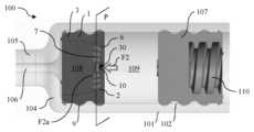
밸브 스토퍼(1)가 더 원위적으로 이동할 수 없기 때문에, 제2 챔버(109) 내의 압력(P2)이 증가되고 힘의 차이(ΔP)는 밸브 개방력(Fop)보다 커지기 시작한다.Since the valve stopper (1) cannot move further distally, the pressure (P2) within the second chamber (109) increases and the force difference (ΔP) begins to become greater than the valve opening force (Fop ).
결과적으로, 제1의 전반적인 실시형태와 관련하여, 분할부가 개방되고, 그에 의해서, 도 3c에 도시된 바와 같이, 제2 조성물이 주입을 위해서 채널까지 상기 분할부를 통과할 수 있게 한다. 이러한 구성에서, 밸브 스토퍼는 주입 위치에 있다.Consequently, with respect to the first overall embodiment, the split section is opened, thereby allowing the second composition to pass through the split section to the channel for injection, as illustrated in Fig. 3c. In this configuration, the valve stopper is in the injection position.
이러한 상황은 또한 도 3e에서 보다 구체적으로 표시되어 있고, 여기에서 제2 조성물에 의해서 멤브레인(2) 상으로 인가되는 힘은 화살표(F2)에 의해서 표시되어 있고, 밸브를 개방하기 위한 힘은 더 작은 화살표(F2a)에 의해서 도시되어 있다.This situation is also illustrated more specifically in FIG. 3e, where the force applied by the second composition onto the membrane (2) is indicated by the arrow (F2) and the force to open the valve is illustrated by the smaller arrow (F2a).
제2의 전반적인 실시형태와 관련하여, 파열 부분(21)이 파열되고, 그에 의해서, 제2 조성물이 주입을 위해서 유체 경로를 따라서, 노치 및 파열된 파열 부분(21)을 통해서, 채널까지 전달될 수 있게 하는 유체 경로(30)를 멤브레인을 통해서 생성한다.In connection with the second overall embodiment, the ruptured portion (21) is ruptured, thereby creating a fluid path (30) through the membrane, which allows the second composition to be delivered along the fluid path, through the notch and the ruptured ruptured portion (21), to the channel for injection.
이러한 상황은 또한 제2의 전반적인 실시형태의 제1 및 제2 실시형태에 대해서 도 12a 및 도 13a에서 보다 구체적으로 표시되어 있고, 여기에서 제2 조성물에 의해서 멤브레인(2) 상으로 인가되는 힘은 화살표(F2)에 의해서 표시되어 있고, 유체 경로를 개방하기 위한 힘은 더 작은 화살표(F2a)에 의해서 도시되어 있다. 유체 경로(30)는 점선에 의해서 도시되어 있다.This situation is also more specifically illustrated in FIGS. 12a and 13a for the first and second embodiments of the second overall embodiment, where the force applied by the second composition onto the membrane (2) is indicated by the arrow (F2) and the force for opening the fluid path is illustrated by the smaller arrow (F2a). The fluid path (30) is illustrated by the dotted line.
도 14 및 도 15는 제2의 전반적인 실시형태의 제1 및 제2 실시형태에 대한 유체 경로(30)의 개방을, 밸브 스토퍼의 전반적인 사시도로 도시한다.Figures 14 and 15 illustrate the opening of the fluid path (30) for the first and second embodiments of the second general embodiment in general perspective views of the valve stopper.
이러한 구성에서, 밸브 스토퍼는 주입 위치에 있다.In this configuration, the valve stopper is in the injection position.
전술한 바와 같이, 이러한 순간에, 제1 조성물의 일부가 제1 챔버(108) 내에 잔류한다. 따라서, 제2 조성물의 주입의 시작 시에, 제1 조성물의 일부 및 적은 양의 제2 조성물이 혼합될 수 있는데, 이는 양 조성물들이 동일한 유체 경로를 통해서 주입되기 때문이다.As mentioned above, at this moment, a portion of the first composition remains within the first chamber (108). Therefore, at the start of the injection of the second composition, a portion of the first composition and a small amount of the second composition may be mixed, since both compositions are injected through the same fluid path.
제2 조성물의 주입의 종료 시에, 플런저 스토퍼(107)가 밸브 스토퍼(1)와 접경된다. 제2 조성물의 일부가 제1 챔버(108) 내에서 잔류하고, 이는 사부피에 상응한다.At the end of the injection of the second composition, the plunger stopper (107) comes into contact with the valve stopper (1). A portion of the second composition remains in the first chamber (108), which corresponds to the dead volume.
밸브 스토퍼(1)는 플런저 스토퍼(107)에 의해서 가해지는 압력 하에서 압궤되고, 압궤는 내부 함몰부에 의해서 시작된다. 따라서, 밸브 스토퍼는, 도 3d에 도시된 바와 같이, 압궤 위치에 있다. 밸브 스토퍼의 압궤는 공동(4)의 부피를 감소시키고, 그에 따라 사부피가 주입된다.The valve stopper (1) is crushed under the pressure applied by the plunger stopper (107), and the crushing is initiated by the internal depression. Therefore, the valve stopper is in the crushing position, as shown in Fig. 3d. The crushing of the valve stopper reduces the volume of the cavity (4), and accordingly, dead volume is injected.
밸브 스토퍼가 근위 공동을 포함하는 경우(미도시)에, 플런저 스토퍼는 유리하게 상기 근위 공동에 피팅(fitting)되는 원위 핀을 포함한다. 이러한 방식으로, 밸브 스토퍼의 근위 공동 내로의 상기 핀의 결합은 제2 조성물을 분할부를 통해서 근위 공동으로부터 배출할 수 있게 한다.Where the valve stopper comprises a proximal cavity (not shown), the plunger stopper advantageously comprises a distal pin that fits into said proximal cavity. In this manner, engagement of said pin into the proximal cavity of the valve stopper allows the second composition to be discharged from the proximal cavity through the split portion.
실시형태에 따라, 휴지 위치의 밸브 스토퍼는 주사기의 원위 단부와 접촉된다. 이러한 구성에서, 제1 챔버의 부피가 최소화된다. 제2 챔버는 주입하고자 하는 조성물을 포함한다. 이러한 구성은 하나의 조성물, 특히 약물만이 주입될 때 특히 유용하고, 상기 약물(예를 들어, 에피네프린)은 오염물질에 매우 민감하고 그에 따라 (예를 들어 바늘의) 글루(glue)/금속 또는 공기로부터 추가적으로 보호될 필요가 있다.According to an embodiment, the valve stopper in the rest position is in contact with the distal end of the syringe. In this configuration, the volume of the first chamber is minimized. The second chamber contains the composition to be injected. This configuration is particularly useful when only one composition, in particular a drug, is to be injected, and the drug (e.g. epinephrine) is very sensitive to contaminants and therefore needs to be additionally protected from glue/metal or air (e.g. of the needle).
바람직한 실시형태에 따라, 흡입 효과를 생성하기 위해서 그리고 비어 있는 제1 챔버를 조성물로 충진할 수 있게 하기 위해서, 밸브 스토퍼가 근위 방향으로 이동된다. 이러한 조성물은 전형적으로 혈액 또는 다른 약물이고, 이러한 경우에, 이러한 동작은 "정맥 테스트" 또는 "재구성"으로 지칭된다.According to a preferred embodiment, the valve stopper is moved proximally to produce an inhalation effect and to allow filling of the empty first chamber with a composition. This composition is typically blood or another drug, in which case this action is referred to as a "venous test" or "reconstitution".
정맥 테스트 또는 재구성 중에, 노치는 체크 밸브 기능(도 3f, 도 12b, 및 도 13b)으로 인해서 폐쇄되어 유지되고, 그에 의해서 흡입된 조성물이 제1 조성물과 혼합되는 것을 방지한다. 흡인력은 화살표(F1)에 의해서 표시되고, 유체 경로를 폐쇄 유지하는, 제2 조성물에 의해서 멤브레인 상으로 가해지는 힘은 더 작은 화살표(F2b)로 표시되어 있다.During venous testing or reconstitution, the notch remains closed due to the check valve function (FIGS. 3f, 12b, and 13b), thereby preventing the aspirated composition from mixing with the first composition. The aspiration force is indicated by the arrow (F1), and the force exerted on the membrane by the second composition, which keeps the fluid path closed, is indicated by the smaller arrow (F2b).
정맥 테스트 또는 재구성은 제1 조성물의 주입 전에 실행될 수 있다. 이러한 경우에, 다른 밸브 스토퍼가 몸통의 원위 단부와 제1 조성물 사이에 제공된다.Venous testing or reconstruction may be performed prior to injection of the first composition. In such a case, another valve stopper is provided between the distal end of the body and the first composition.
대안적으로, 정맥 테스트 또는 재구성은 제1 조성물의 주입 중에 실행될 수 있다. 이러한 경우에, 주입은 잠시 중단되고, 정맥 테스트가 수행된다. 이어서, 제1 조성물의 주입이 재개된다.Alternatively, the venous testing or reconstitution may be performed during the infusion of the first composition. In this case, the infusion is briefly interrupted, the venous testing is performed, and the infusion of the first composition is then resumed.
본 발명은 또한 적어도 하나의 조성물을 주입하기 위한 의료용 주입 장치(100)에 관한 것이다. 상기 의료용 주입 장치는:The present invention also relates to a medical infusion device (100) for injecting at least one composition, said medical infusion device comprising:
- 근위 단부(103)로부터 원위 단부(104)까지 연장되는 몸통(101),- A body (101) extending from the proximal end (103) to the distal end (104);
- 몸통(101) 내측에서 병진운동적으로 이동 가능하게 구성되는 플런저 스토퍼(107),- A plunger stopper (107) configured to be translationally movable inside the body (101),
- 몸통의 원위 단부(104)와 플런저 스토퍼(107) 사이에 배열되고, 몸통(101)의 내측에서 병진운동적으로 이동 가능하게 구성된, 전술한 바와 같은 밸브 스토퍼(1)로서, 밸브 스토퍼(1)의 측방향 벽(3)이 몸통의 내부 표면(102)과 밀봉 가능하게 결합되는, 밸브 스토퍼(1)를 포함한다.- A valve stopper (1) as described above, arranged between the distal end (104) of the body and the plunger stopper (107) and configured to be translationally movable inside the body (101), wherein the lateral wall (3) of the valve stopper (1) is sealingly coupled with the inner surface (102) of the body.
실시예Example
주입력의 측정Measurement of injection force
제1의 전반적인 실시형태에 따른 본 발명에 따른 밸브 스토퍼의, 그리고 종래 기술에서 알려진 스토퍼의 주입력을 결정하기 위해서, 테스트를 수행하였다.In order to determine the injection force of the valve stopper according to the first general embodiment of the present invention and of stoppers known in the prior art, tests were performed.
종래 기술에서, 예를 들어 US4929230에서 알려진 스토퍼는, 스토퍼의 원주를 따라서 반경방향 외측으로 연장되는 리브를 포함한다. 상기 스토퍼가 사용될 때, 조성물은 리브들과 몸통의 내부 표면 사이의 통로를 통과하도록 의도된다. 종래의 설계는 어떠한 분할부도 포함하지 않는다. 종래 기술에서 알려진 상기 스토퍼의 총 부피는 약 421 mm3이다. 비교로서, 본 발명의 밸브 스토퍼의 총 부피는 약 162 mm3이다.In the prior art, for example, a stopper known from US4929230 comprises ribs extending radially outwardly along the circumference of the stopper. When said stopper is used, the composition is intended to pass through a passage between the ribs and the inner surface of the body. The prior art design does not comprise any splitting portions. The total volume of said stoppers known in the prior art is about 421 mm3 . In comparison, the total volume of the valve stopper of the present invention is about 162 mm3 .
밸브 스토퍼가 밀봉 위치에 있는 주사기가 사용되었고, 이는 (도 3a에 상응하게) 상기 밸브 스토퍼가 주사기의 몸통의 원위 단부에 접경되지 않는다는 것을 의미한다. 몸통의 원위 단부와 밸브 스토퍼/종래 기술의 스토퍼 사이의 그리고 밸브 스토퍼/종래 기술의 스토퍼와 플런저 스토퍼 사이의 챔버들 모두는 주사기로부터 배출하고자 하는 조성물을 포함한다. 주사기는 테스트 벤치 상에 장착된다. 플런저 스토퍼는 원위 방향으로 기계적으로 이동되고, 플런저 스토퍼 상으로 가해지는 힘은 벤치의 변위에 따라 기록된다. 이러한 힘은 밸브 스토퍼/종래 기술의 스토퍼의 주입력에 상응한다. 상기 힘은 밸브 스토퍼/종래 기술의 스토퍼의 밸브 개방력(Fop)을 포함하고, 이는 (도 3b의 구성에 상응하는) 곡선 주입력 상의; 그리고 조성물이 주입될 때의 활주력으로의 국소적인 피크에 상응한다. 밸브 스토퍼의 상기 주입력(N)은 벤치 변위(mm)에 따라 도 16에 표시되어 있다. 밸브 개방력 및 최대 활주력 모두가 표시되어 있다. 본 발명에 따른 밸브 스토퍼의 주입력은 실선으로 표시된 반면, 종래 기술의 스토퍼의 주입력은 점선으로 표시되어 있다.A syringe was used in which the valve stopper is in the sealing position, meaning that (corresponding to FIG. 3a) the valve stopper does not abut the distal end of the syringe body. Both the chambers between the distal end of the body and the valve stopper/prior art stopper and between the valve stopper/prior art stopper and the plunger stopper contain the composition to be discharged from the syringe. The syringe is mounted on a test bench. The plunger stopper is mechanically moved in the distal direction and the force exerted on the plunger stopper is recorded as a function of the displacement of the bench. This force corresponds to the injection force of the valve stopper/prior art stopper. The force comprises the valve opening force (Fop ) of the valve stopper/prior art stopper, which corresponds to the local peak on the curve injection force (corresponding to the configuration of FIG. 3b ) and to the gliding force when the composition is injected. The above injection force (N) of the valve stopper is plotted against the bench displacement (mm) in Fig. 16. Both the valve opening force and the maximum sliding force are plotted. The injection force of the valve stopper according to the present invention is plotted as a solid line, while the injection force of the stopper of the prior art is plotted as a dotted line.
주입력은 12 mm의 벤치 변위에 대해서 약 12 N까지 증가된다. 이는 밸브 스토퍼의 이동에서의 설정에 상응하고, 특정 힘이 상기 밸브 스토퍼 상으로 인가될 것을 요구한다.The injection force increases to about 12 N for a bench displacement of 12 mm. This corresponds to a setting in the travel of the valve stopper and requires a certain force to be applied onto said valve stopper.
이어서, 활주력은 30 mm의 벤치 변위까지 실질적으로 일정하게 유지된다. 이는, 초기에 포함된 제1 조성물을 몸통의 원위 단부와 밸브 스토퍼 사이에 주입하기 위한, 원위 방향을 따른 밸브 스토퍼의 변위에 상응한다. 상기 힘은 종래의 설계에서 관찰되는 힘과 동일하다.Subsequently, the gliding force remains substantially constant up to a bench displacement of 30 mm. This corresponds to the displacement of the valve stopper along the distal direction for injecting the initially included first composition between the distal end of the body and the valve stopper. The force is identical to that observed in conventional designs.
이어서, 주입력은, 벤치 변위가 35 mm에 도달할 때, 밸브 개방력(Fop)에 상응하는 17.5 N의 곡선의 최대값까지 급격하게 증가된다.Subsequently, the injection force increases rapidly to a maximum value of the curve of 17.5 N, corresponding to the valve opening force (Fop ), when the bench displacement reaches 35 mm.
이어서, 주입력은, 제2 조성물을 주입하기 위한 최대 활주력에 상응하는 약 14 N의 중간 값(mean value)까지 감소된다.Subsequently, the injection force is reduced to a mean value of about 14 N, corresponding to the maximum sliding force for injecting the second composition.
이어서, 밸브 스토퍼가 압궤되고, 제2 주입이 종료되며, 이는 주입력의 강력한 감소를 유도한다.Subsequently, the valve stopper collapses and the second injection is terminated, which leads to a strong decrease in the injection force.
밸브 개방력 및 활주력의 평균 값의 결정Determination of average values of valve opening force and sliding force
이전의 테스트를 제1의 전반적인 실시형태에 따른 본 발명의 몇 개의 밸브 스토퍼 및 종래 기술의 몇 개의 스토퍼에 대해서 몇 차례 실행하였다. 각각의 테스트에서 측정된 상기의 상이한 스토퍼들에 대한 밸브 개방력(Fop)의 그리고 최대 활주력의 평균 값들을 도 17의 그래프 및 도 18의 그래프에서 각각 도시하였다.The previous tests were performed several times on several valve stoppers of the present invention according to the first general embodiment and several stoppers of the prior art. The average values of the valve opening force (Fop ) and the maximum sliding force for the above different stoppers measured in each test are plotted in the graphs of Fig. 17 and Fig. 18, respectively.
도 17과 관련하여, 종래의 설계와 관련하여, 밸브 개방력의 평균 값은 27.5 N이다. 표준 편차가 또한 2개의 세그먼트에 의해서 경계 한정된 수직 선에 의해서 그래프 내에 표시되어 있다. 표준 변동은 작고, 이는, 상이한 측정들이, 27.5 N의 평균 값에 가까운 밸브 개방력의 값들을 초래한다는 것을 의미한다.With regard to Fig. 17, with regard to the conventional design, the mean value of the valve opening force is 27.5 N. The standard deviation is also indicated in the graph by a vertical line delimited by two segments. The standard variation is small, which means that different measurements result in values of the valve opening force close to the mean value of 27.5 N.
본 발명의 밸브 스토퍼("밸브 설계")와 관련하여, 밸브 개방력의 평균 값은 15.5 N이고, 이는 종래의 설계의 평균 값보다 훨씬 더 작다. 표준 편차가 큰데, 이는, 테스트가, 분할부의 두께에 직접적으로 영향을 미치고, 그에 의해서 밸브 개방력에 또한 영향을 미치는, 멤브레인의 상이한 두께들을 나타내는 밸브 스토퍼들로 실행되었기 때문이다.With respect to the valve stopper of the present invention (“valve design”), the average value of the valve opening force is 15.5 N, which is much smaller than that of conventional designs. The standard deviation is large, because the tests were performed with valve stoppers exhibiting different thicknesses of the membrane, which directly affects the thickness of the split section and thereby also the valve opening force.
따라서, 본 발명의 밸브 스토퍼는 종래의 설계보다 훨씬 더 작은 밸브 개방력을 초래한다. 밸브 개방력은 사용자에 의한 조성물의 주입을 크게 촉진하고 긴장 부상을 방지할 수 있을 정도로 충분히 작고, 약제 조성물이 주입 전에 그 챔버로부터 우발적으로 빠져 나가는 것을 방지하는 것에 의해서 몸통의 타이트한 밀봉을 보장할 정도로 충분히 크다.Thus, the valve stopper of the present invention results in a much smaller valve opening force than conventional designs. The valve opening force is sufficiently small to greatly facilitate injection of the composition by the user and prevent strain injuries, and sufficiently large to ensure a tight seal of the body by preventing accidental escape of the pharmaceutical composition from its chamber prior to injection.
도 18과 관련하여, 종래의 설계와 관련하여, 최대 활주력의 평균 값은 22.1 N이다. 표준 편차는 작고, 이는, 상이한 측정들이, 22.1 N의 평균 값에 가까운 활주력의 값들을 초래한다는 것을 의미한다.With respect to Fig. 18, with respect to the conventional design, the average value of the maximum gliding force is 22.1 N. The standard deviation is small, which means that different measurements result in values of the gliding force close to the average value of 22.1 N.
본 발명의 밸브 스토퍼와 관련하여, 최대 활주력의 평균 값은 12.7 N이고, 이는 종래의 설계의 평균 값보다 훨씬 더 작다. 표준 편차는 평균인데, 이는, 테스트가, 밸브 스토퍼의 중량에 영향을 미치고, 그에 의해서 활주력에 또한 영향을 미치는, 멤브레인의 상이한 두께들을 나타내는 밸브 스토퍼들로 실행되었기 때문이다.With respect to the valve stopper of the present invention, the average value of the maximum sliding force is 12.7 N, which is much smaller than the average value of the conventional design. The standard deviation is the average, because the tests were performed with valve stoppers exhibiting different thicknesses of the membrane, which affects the weight of the valve stopper and thereby also the sliding force.
따라서, 본 발명의 밸브 스토퍼는 종래의 설계보다 훨씬 더 작은 최대 활주력을 초래한다. 이는, 하나 이상의 리브가 조성물을 위한 통로를 형성하지 않고, 그 대신 몸통의 내부 표면과 영구적으로 접촉되기 때문이고, 그러한 영구적인 접촉은 밸브 스토퍼가 주사기의 축과 관련하여 오프셋되는 것을 방지하고 주입을 더 매끄럽게 한다. 밸브 개방력은, 사용자에 의한 조성물의 주입을 크게 촉진하고 긴장 부상을 방지할 수 있을 정도로 충분히 작고, 약제 조성물이 주입 전에 그 챔버로부터 우발적으로 빠져 나가는 것을 방지하는 것에 의해서 몸통의 타이트한 밀봉을 보장할 정도로 충분히 크다.Thus, the valve stopper of the present invention results in a much smaller maximum sliding force than prior art designs. This is because the one or more ribs do not form a passage for the composition, but instead are in permanent contact with the inner surface of the barrel, which permanent contact prevents the valve stopper from being offset relative to the axis of the syringe, thereby making injection smoother. The valve opening force is sufficiently small to greatly facilitate injection of the composition by the user and prevent strain injuries, and sufficiently large to ensure a tight seal of the barrel by preventing accidental escape of the pharmaceutical composition from its chamber prior to injection.
Claims (20)
Translated fromKorean- 근위 면(6) 및 원위 면(7)을 포함하는 멤브레인(2)으로서, 상기 몸통의 제1의 원위 챔버(108)를 상기 몸통의 제2의 근위 챔버(109)로부터 분리하도록 구성되는, 멤브레인(2),
- 상기 멤브레인(2)으로부터 원위적으로, 또는 원위적 및 근위적 모두로 연장되어 적어도 원위 공동(4)을 형성하는 측방향 벽(3)으로서, 상기 몸통의 내부 표면(102)과 밀봉 결합되도록 구성되는 원주방향 밀봉 표면(8)을 포함하는, 측방향 벽(3)을 포함하는, 밸브 스토퍼(1)에 있어서,
상기 멤브레인(2)의 근위 면(6)이 곡선형이며 멤브레인의 근위면의 곡률의 정점이 멤브레인의 원위면을 향해서 연장되도록 오목한 형상을 나타내고, 상기 멤브레인(2)은 근위 면(6)과 원위 면(7) 사이에서 상기 멤브레인의 두께의 적어도 일부를 통해서 연장되는 노치(10, 20)를 포함하고, 상기 노치(10, 20)는, 유체를 상기 제2 챔버(109)로부터 상기 제1 챔버(108)로만 전달하기 위해서 조성물에 의해서 상기 멤브레인(2)의 근위 면(6) 상으로 인가되는 압력에 따라, 상기 근위 면(6)으로부터 상기 원위 면(7)까지 상기 멤브레인(2)을 통한 유체 경로(30)를 선택적으로 생성하도록 구성되는 것을 특징으로 하는, 밸브 스토퍼(1).A valve stopper (1) configured to be placed inside a body (101) of an injection device (100) for injecting at least one composition through a distal end (104) of the body, wherein the valve stopper (1) comprises:
- A membrane (2) comprising a proximal face (6) and a distal face (7), configured to separate a first distal chamber (108) of the body from a second proximal chamber (109) of the body,
- A valve stopper (1) comprising a lateral wall (3) extending distally from the membrane (2), or both distally and proximally, to form at least a distal cavity (4), the lateral wall comprising a circumferential sealing surface (8) configured to sealingly engage with the inner surface (102) of the body,
A valve stopper (1), characterized in that the proximal surface (6) of the membrane (2) is curved and has a concave shape such that the peak of the curvature of the proximal surface of the membrane extends toward the distal surface of the membrane, and the membrane (2) includes a notch (10, 20) extending through at least a part of the thickness of the membrane between the proximal surface (6) and the distal surface (7), and the notch (10, 20) is configured to selectively create a fluid path (30) through the membrane (2) from the proximal surface (6) to the distal surface (7) depending on a pressure applied by the composition onto the proximal surface (6) of the membrane (2) so as to transfer the fluid only from the second chamber (109) to the first chamber (108).
상기 측방향 벽(3)은 원위 방향으로 가해지는 기계적 압력 하에서 상기 밸브 스토퍼(1)의 압궤를 유도하도록 구성되는 내부 함몰부(13)를 포함하는, 밸브 스토퍼(1).In the first paragraph,
A valve stopper (1), wherein the lateral wall (3) includes an internal recess (13) configured to induce collapse of the valve stopper (1) under mechanical pressure applied in a distal direction.
상기 내부 함몰부(13)는 상기 밸브 스토퍼(1)의 원주를 따라서 상기 측방향 벽(3) 내에서 연장되는 환형 홈인, 밸브 스토퍼(1).In the second paragraph,
The above internal recess (13) is an annular groove extending within the lateral wall (3) along the circumference of the valve stopper (1).
상기 밸브 스토퍼(1)는, 중간 리브 및 2개의 측방향 리브를 포함하는, 3개의 리브(9)를 포함하고, 상기 멤브레인(2)은 상기 중간 리브와 정렬되는, 밸브 스토퍼(1).In any one of claims 1 to 3,
The valve stopper (1) comprises three ribs (9), including a middle rib and two lateral ribs, and the membrane (2) is aligned with the middle rib.
상기 노치(20)는 상기 멤브레인(2)의 두께의 일부만에서 연장되고, 그에 의해서 상기 노치(20)가 횡단하지 않는 상기 멤브레인의 두께 내에서 파열 부분(21)을 경계 한정하고, 상기 파열 부분(21)은 상기 조성물에 의해서 가해지는 결정된 압력 하에서 상기 노치(20)를 따라서 파열되어 상기 유체 경로(30)를 생성하도록 구성되는, 밸브 스토퍼.In any one of claims 1 to 3,
A valve stopper, wherein the notch (20) extends only through a portion of the thickness of the membrane (2), thereby defining a rupture portion (21) within the thickness of the membrane that the notch (20) does not traverse, and wherein the rupture portion (21) is configured to rupture along the notch (20) under a determined pressure applied by the composition to create the fluid path (30).
상기 멤브레인의 파열 부분(21)은, 상기 조성물에 의해서 상기 멤브레인(2)의 근위 면(6)에 가해지는 압력에 따라, 상기 공동(4)을 개방 또는 폐쇄하도록 구성되는 밸브를 형성하는, 밸브 스토퍼.In paragraph 5,
A valve stopper, wherein the ruptured portion (21) of the membrane forms a valve configured to open or close the cavity (4) depending on the pressure applied to the proximal surface (6) of the membrane (2) by the composition.
상기 노치(20)는 상기 멤브레인의 원위 면(7)으로부터 상기 멤브레인(2)의 일부를 통해서 연장되는, 밸브 스토퍼.In any one of claims 1 to 3,
A valve stopper, wherein the notch (20) extends from the distal surface (7) of the membrane through a portion of the membrane (2).
상기 노치(20)의 깊이는 0.1 mm 이상, 또는 0.2 mm이상인, 밸브 스토퍼.In paragraph 5,
A valve stopper, wherein the depth of the above notch (20) is 0.1 mm or more, or 0.2 mm or more.
상기 노치(20)가 길다란 형상을 가지거나, 십자가의 중심(26)에서 교차되는 2개의 세그먼트(25)를 포함하는 십자가의 형태인, 밸브 스토퍼.In paragraph 5,
A valve stopper, wherein the above notch (20) has an elongated shape or is in the shape of a cross including two segments (25) intersecting at the center (26) of the cross.
상기 노치는, 상기 근위 면(6)과 상기 원위 면(7) 사이에서 상기 멤브레인(2)을 통해서 연장되는 분할부(10)이고, 상기 분할부는, 상기 조성물에 의해서 상기 멤브레인(2)의 근위 면(6)에 가해지는 압력에 따라, 상기 공동(4)을 개방 또는 폐쇄하도록 구성되는 밸브를 형성하는, 밸브 스토퍼.In any one of claims 1 to 3,
A valve stopper, wherein the notch is a dividing portion (10) extending through the membrane (2) between the proximal face (6) and the distal face (7), the dividing portion forming a valve configured to open or close the cavity (4) depending on the pressure applied to the proximal face (6) of the membrane (2) by the composition.
상기 노치(10)는 상기 멤브레인의 근위 면(6)의 중심을 통과하는 라인(11)의 형태인, 밸브 스토퍼(1).In any one of claims 1 to 3,
The valve stopper (1) has the above notch (10) in the form of a line (11) passing through the center of the proximal face (6) of the membrane.
상기 노치(10)는 2개의 세그먼트(12)를 더 포함하고, 각각의 세그먼트는 상기 라인(11)의 단부의 양 측면 상에서 연장되는, 밸브 스토퍼(1).In Article 11,
A valve stopper (1) having the above notch (10) further comprising two segments (12), each segment extending on either side of the end of the line (11).
상기 멤브레인(2)의 원위 면(7)은 평면형 형상 또는 볼록한 형상을 나타내고, 상기 원위 면의 곡률은 상기 근위 면(6)으로부터 멀리 연장되는, 밸브 스토퍼(1).In any one of claims 1 to 3,
A valve stopper (1) in which the distal surface (7) of the membrane (2) has a planar or convex shape, and the curvature of the distal surface extends away from the proximal surface (6).
상기 노치(10)는, 상기 공동(4)의 직경의 1/4 초과 및 상기 공동(4)의 직경 미만인 길이를 나타내는, 밸브 스토퍼(1).In any one of claims 1 to 3,
The valve stopper (1) has the above notch (10) indicating a length that is more than 1/4 of the diameter of the cavity (4) and less than the diameter of the cavity (4).
- 근위 단부(103)로부터 원위 단부(104)까지 연장되는 몸통(101),
- 상기 몸통(101) 내측에서 병진운동적으로 이동 가능하게 구성되는 플런저 스토퍼(107),
- 상기 몸통(101)의 내측에서 병진운동적으로 이동 가능하게 구성된, 상기 몸통의 원위 단부(104)와 상기 플런저 스토퍼(107) 사이에 배열되는, 제1항 내지 제3항 중 어느 한 항에 따른 밸브 스토퍼(1)로서, 상기 밸브 스토퍼(1)의 측방향 벽(3)이 상기 몸통의 내부 표면(102)과 밀봉 가능하게 결합되는, 밸브 스토퍼(1)를 포함하는, 의료용 주입 장치(100).A medical infusion device (100) for injecting at least one composition:
- A body (101) extending from the proximal end (103) to the distal end (104);
- A plunger stopper (107) configured to be translationally movable inside the body (101),
- A medical infusion device (100) comprising a valve stopper (1) according to any one of claims 1 to 3, arranged between a distal end (104) of the body and the plunger stopper (107), configured to be translationally movable inside the body (101), wherein a lateral wall (3) of the valve stopper (1) is sealably coupled with an inner surface (102) of the body.
상기 의료용 주입 장치는 2개의 조성물을 순차적으로 주입하도록 구성되고, 상기 밸브 스토퍼(1)는 상기 몸통의 2개의 챔버(108, 109)를 분리하고, 상기 밸브 스토퍼(1)와 상기 몸통의 원위 단부(104) 사이의 제1 챔버(108)는 제1 조성물을 포함하고, 상기 밸브 스토퍼(1)와 상기 플런저 스토퍼(107) 사이의 제2 챔버(109)는 제2 조성물을 포함하는, 의료용 주입 장치(100).In Article 15,
A medical infusion device (100) configured to sequentially inject two compositions, wherein the valve stopper (1) separates two chambers (108, 109) of the body, the first chamber (108) between the valve stopper (1) and the distal end (104) of the body contains the first composition, and the second chamber (109) between the valve stopper (1) and the plunger stopper (107) contains the second composition.
상기 밸브 스토퍼(1)는 연속적인 이하의 위치들:
- 상기 유체 경로(30)가 폐쇄되는, 휴지 위치,
- 밀봉 위치로서, 상기 밸브 스토퍼(1)가 상기 휴지 위치보다 더 원위에 있고, 상기 유체 경로(30)가 폐쇄되며, 상기 멤브레인(2)의 근위 면(6)이 상기 노치(10)의 밸브 개방력(Fop)보다 작은 압력을 받는, 밀봉 위치,
- 주입 위치로서, 상기 밸브 스토퍼(1)가 상기 몸통(101)의 원위 단부(104)와 접경되고, 상기 노치(10)의 밸브 개방력(Fop)보다 큰 압력이 상기 멤브레인(2)의 근위 면(6)에 인가되는 것으로 인해서 상기 유체 경로(30)가 개방되는, 주입 위치를 나타내는, 의료용 주입 장치(100).In Article 15,
The above valve stopper (1) has the following consecutive positions:
- Rest position, where the above fluid path (30) is closed;
- A sealing position, in which the valve stopper (1) is located more distal than the rest position, the fluid path (30) is closed, and the proximal face (6) of the membrane (2) is subjected to a pressure less than the valve opening force (Fop ) of the notch (10).
- A medical infusion device (100) indicating an injection position, wherein the valve stopper (1) is in contact with the distal end (104) of the body (101), and the fluid path (30) is opened by applying a pressure greater than the valve opening force (Fop ) of the notch (10) to the proximal surface (6) of the membrane (2).
상기 밸브 스토퍼(1)가 압궤 위치를 더 나타내고, 상기 플런저 스토퍼(107)는 상기 밸브 스토퍼(1)와 접경되고, 상기 밸브 스토퍼(1)가 압궤되는, 의료용 주입 장치(100).In Article 17,
A medical infusion device (100), wherein the above valve stopper (1) further indicates a collapse position, the plunger stopper (107) is in contact with the valve stopper (1), and the valve stopper (1) is collapsed.
주사기인, 의료용 주입 장치(100).In Article 15,
A syringe, a medical injection device (100).
상기 멤브레인의 근위 면은, 상기 몸통의 내경보다 1.2 내지 2.3배 더 큰 곡률 반경을 나타내는, 의료용 주입 장치(100).In Article 15,
A medical infusion device (100), wherein the proximal surface of the membrane exhibits a radius of curvature that is 1.2 to 2.3 times larger than the inner diameter of the body.
Priority Applications (1)
| Application Number | Priority Date | Filing Date | Title |
|---|---|---|---|
| KR1020257009365AKR20250047406A (en) | 2019-02-27 | 2020-02-25 | Valve stopper for a medical injection device and medical injection device for injecting at least one composition |
Applications Claiming Priority (5)
| Application Number | Priority Date | Filing Date | Title |
|---|---|---|---|
| EP19305230 | 2019-02-27 | ||
| EP19305230.5 | 2019-02-27 | ||
| EP19305647.0 | 2019-05-22 | ||
| EP19305647 | 2019-05-22 | ||
| PCT/EP2020/054902WO2020173938A1 (en) | 2019-02-27 | 2020-02-25 | Valve stopper for a medical injection device and medical injection device for injecting at least one composition |
Related Child Applications (1)
| Application Number | Title | Priority Date | Filing Date |
|---|---|---|---|
| KR1020257009365ADivisionKR20250047406A (en) | 2019-02-27 | 2020-02-25 | Valve stopper for a medical injection device and medical injection device for injecting at least one composition |
Publications (2)
| Publication Number | Publication Date |
|---|---|
| KR20210131356A KR20210131356A (en) | 2021-11-02 |
| KR102788920B1true KR102788920B1 (en) | 2025-04-01 |
Family
ID=69593716
Family Applications (2)
| Application Number | Title | Priority Date | Filing Date |
|---|---|---|---|
| KR1020217028474AActiveKR102788920B1 (en) | 2019-02-27 | 2020-02-25 | Valve stopper for a medical infusion device and a medical infusion device for injecting at least one composition |
| KR1020257009365APendingKR20250047406A (en) | 2019-02-27 | 2020-02-25 | Valve stopper for a medical injection device and medical injection device for injecting at least one composition |
Family Applications After (1)
| Application Number | Title | Priority Date | Filing Date |
|---|---|---|---|
| KR1020257009365APendingKR20250047406A (en) | 2019-02-27 | 2020-02-25 | Valve stopper for a medical injection device and medical injection device for injecting at least one composition |
Country Status (9)
| Country | Link |
|---|---|
| US (1) | US20220134003A1 (en) |
| EP (1) | EP3930795A1 (en) |
| JP (1) | JP7531505B2 (en) |
| KR (2) | KR102788920B1 (en) |
| CN (1) | CN113498351B (en) |
| BR (1) | BR112021016442A2 (en) |
| CA (1) | CA3129652A1 (en) |
| MX (2) | MX2021009713A (en) |
| WO (1) | WO2020173938A1 (en) |
Families Citing this family (11)
| Publication number | Priority date | Publication date | Assignee | Title |
|---|---|---|---|---|
| GB202104609D0 (en) | 2021-03-31 | 2021-05-12 | Sevenless Therapeutics Ltd | New Treatments for Pain |
| CA3213593A1 (en) | 2021-03-31 | 2022-10-06 | Sevenless Therapeutics Limited | Sos1 inhibitors and ras inhibitors for use in the treatment of pain |
| EP4598538A1 (en) | 2022-10-05 | 2025-08-13 | Sevenless Therapeutics Limited | New treatments for pain |
| US20240148973A1 (en)* | 2022-11-09 | 2024-05-09 | Becton, Dickinson And Company | Dual chamber syringe assembly with floating stopper |
| US20240173480A1 (en)* | 2022-11-30 | 2024-05-30 | Becton, Dickinson And Company | Syringe with concentric dual chambers |
| US20240173481A1 (en)* | 2022-11-30 | 2024-05-30 | Becton, Dickinson And Company | Syringe with tandem dual chambers |
| US20240252758A1 (en)* | 2023-01-31 | 2024-08-01 | Credence Medsystems, Inc. | Injection system and method |
| WO2024242865A1 (en)* | 2023-05-24 | 2024-11-28 | Becton, Dickinson And Company | Stoppering tool system for installing a valved stopper in a syringe barrel |
| EP4541387A1 (en) | 2023-10-16 | 2025-04-23 | Becton Dickinson France | Sequential-injection syringe |
| WO2025184096A1 (en)* | 2024-02-26 | 2025-09-04 | Becton, Dickinson And Company | Valve stopper for a multi-chamber medical injection device |
| WO2025184100A1 (en)* | 2024-02-26 | 2025-09-04 | Becton, Dickinson And Company | Valve stopper for a multi-chamber medical injection device |
Citations (8)
| Publication number | Priority date | Publication date | Assignee | Title |
|---|---|---|---|---|
| JP2000210384A (en)* | 1999-01-26 | 2000-08-02 | Naigai Kasei Kk | Medical stopper |
| US20040102738A1 (en) | 2002-11-26 | 2004-05-27 | Medical Ventures, L.L.C. | Pressure actuated flow control valve |
| US20060142701A1 (en) | 2004-05-03 | 2006-06-29 | Infusive Technologies, Llc | Mixing syringe with and without flush |
| JP2007535987A (en)* | 2004-05-03 | 2007-12-13 | インヒュースィヴ・テクノロジーズ・エルエルシー | Multi-chamber sequential dose dispensing syringe |
| WO2008045042A1 (en) | 2006-10-10 | 2008-04-17 | Infusive Technologies, Llc | Multi-chamber, sequential dose dispensing syringe |
| US20110224611A1 (en) | 2010-03-15 | 2011-09-15 | Becton, Dickinson And Company | Medical device including an air evacuation system |
| US20160346481A1 (en) | 2013-11-14 | 2016-12-01 | Hans Haindl | Syringe for sequential injection of active ingredients |
| WO2017170634A1 (en)* | 2016-03-30 | 2017-10-05 | テルモ株式会社 | Seal member, syringe assembly, and prefilled syringe |
Family Cites Families (19)
| Publication number | Priority date | Publication date | Assignee | Title |
|---|---|---|---|---|
| US4929230A (en) | 1988-09-30 | 1990-05-29 | Pfleger Frederick W | Syringe construction |
| IS4223A (en)* | 1993-11-03 | 1995-05-04 | Astra Ab | Apparatus for mixing pharmaceutical composition with another substance |
| JPH09173450A (en)* | 1995-12-26 | 1997-07-08 | Nissho Corp | Prefilled syringe |
| FR2822710B1 (en) | 2001-03-27 | 2004-04-02 | Lab Contactologie Appl Lca | SYRINGE FOR VISCOLEASTIC SOLUTIONS |
| US6723074B1 (en)* | 2002-04-09 | 2004-04-20 | Thor R. Halseth | Sequential delivery syringe |
| CN2621701Y (en)* | 2003-04-18 | 2004-06-30 | 刘文照 | Environmental protection syringe |
| US9933079B2 (en)* | 2004-01-29 | 2018-04-03 | Angiodynamics, Inc. | Stacked membrane for pressure actuated valve |
| JP4686202B2 (en) | 2005-02-02 | 2011-05-25 | 大成化工株式会社 | Syringe |
| WO2009094345A1 (en)* | 2008-01-23 | 2009-07-30 | Mallinckrodt Inc. | Plunger adapter coaxial syringe system |
| US20110087093A1 (en)* | 2009-10-09 | 2011-04-14 | Navilyst Medical, Inc. | Valve configurations for implantable medical devices |
| KR20110041826A (en)* | 2009-10-16 | 2011-04-22 | 조희민 | Syringes with check valves for heterogeneous liquid mixing |
| WO2011092536A1 (en)* | 2010-01-26 | 2011-08-04 | Becton Dickinson France | Drug cartrigde different inner surface conditions |
| US9289562B2 (en)* | 2011-04-18 | 2016-03-22 | THORNE CONSULTING and INTELETUAL PROPERTY, LLC | Pressure actuated valve for multi-chamber syringe applications |
| US9950114B2 (en)* | 2011-05-13 | 2018-04-24 | Thorne Consulting For International Property, Llc | Dual-chamber syringe and associated connecting systems |
| WO2014004695A1 (en)* | 2012-06-26 | 2014-01-03 | Glucago, Llc | Reconstitution device |
| AU2014318264B2 (en)* | 2013-09-16 | 2018-10-04 | Zoetis Services Llc | Assembly for sequentially delivering substances, and associated methods |
| WO2017069818A1 (en)* | 2015-10-23 | 2017-04-27 | Thorne Consulting And Intellectual Property, Llc | Dual-chamber syringe and associated connecting systems |
| KR20180002647U (en)* | 2017-02-28 | 2018-09-05 | 라보라뜨와 메디동 소시에떼아노님 | Injection syringe for intra-articular administration |
| RU2742443C1 (en)* | 2017-10-23 | 2021-02-05 | Аптаргруп, Инк. | Valve |
- 2020
- 2020-02-25JPJP2021549995Apatent/JP7531505B2/enactiveActive
- 2020-02-25EPEP20705751.4Apatent/EP3930795A1/enactivePending
- 2020-02-25BRBR112021016442Apatent/BR112021016442A2/enunknown
- 2020-02-25USUS17/434,103patent/US20220134003A1/enactivePending
- 2020-02-25CNCN202080016838.3Apatent/CN113498351B/enactiveActive
- 2020-02-25CACA3129652Apatent/CA3129652A1/enactivePending
- 2020-02-25MXMX2021009713Apatent/MX2021009713A/enunknown
- 2020-02-25KRKR1020217028474Apatent/KR102788920B1/enactiveActive
- 2020-02-25WOPCT/EP2020/054902patent/WO2020173938A1/ennot_activeCeased
- 2020-02-25KRKR1020257009365Apatent/KR20250047406A/enactivePending
- 2021
- 2021-08-12MXMX2025004048Apatent/MX2025004048A/enunknown
Patent Citations (8)
| Publication number | Priority date | Publication date | Assignee | Title |
|---|---|---|---|---|
| JP2000210384A (en)* | 1999-01-26 | 2000-08-02 | Naigai Kasei Kk | Medical stopper |
| US20040102738A1 (en) | 2002-11-26 | 2004-05-27 | Medical Ventures, L.L.C. | Pressure actuated flow control valve |
| US20060142701A1 (en) | 2004-05-03 | 2006-06-29 | Infusive Technologies, Llc | Mixing syringe with and without flush |
| JP2007535987A (en)* | 2004-05-03 | 2007-12-13 | インヒュースィヴ・テクノロジーズ・エルエルシー | Multi-chamber sequential dose dispensing syringe |
| WO2008045042A1 (en) | 2006-10-10 | 2008-04-17 | Infusive Technologies, Llc | Multi-chamber, sequential dose dispensing syringe |
| US20110224611A1 (en) | 2010-03-15 | 2011-09-15 | Becton, Dickinson And Company | Medical device including an air evacuation system |
| US20160346481A1 (en) | 2013-11-14 | 2016-12-01 | Hans Haindl | Syringe for sequential injection of active ingredients |
| WO2017170634A1 (en)* | 2016-03-30 | 2017-10-05 | テルモ株式会社 | Seal member, syringe assembly, and prefilled syringe |
Also Published As
| Publication number | Publication date |
|---|---|
| BR112021016442A2 (en) | 2021-11-09 |
| EP3930795A1 (en) | 2022-01-05 |
| KR20210131356A (en) | 2021-11-02 |
| CA3129652A1 (en) | 2020-09-03 |
| CN113498351B (en) | 2023-12-12 |
| CN113498351A (en) | 2021-10-12 |
| JP7531505B2 (en) | 2024-08-09 |
| WO2020173938A1 (en) | 2020-09-03 |
| MX2025004048A (en) | 2025-05-02 |
| MX2021009713A (en) | 2021-09-08 |
| JP2022522172A (en) | 2022-04-14 |
| KR20250047406A (en) | 2025-04-03 |
| US20220134003A1 (en) | 2022-05-05 |
Similar Documents
| Publication | Publication Date | Title |
|---|---|---|
| KR102788920B1 (en) | Valve stopper for a medical infusion device and a medical infusion device for injecting at least one composition | |
| JP7053709B2 (en) | Vial transfer and injection equipment and methods | |
| JP7384467B2 (en) | Piston for use in syringes | |
| CN113966240B (en) | Device and method for precise dose delivery | |
| JP3097951B2 (en) | Continuous motion stopper | |
| US7018356B2 (en) | Method and apparatus for adjusting the contents of a needle-less injector | |
| ZA200502816B (en) | Single-use syringe | |
| CN115315283B (en) | Stopper for medical injection device | |
| US9802002B2 (en) | Training cartridge for a drug delivery device | |
| US2453589A (en) | Hypodermic syringe and ampoule therefor | |
| US2453591A (en) | Hypodermic syringe | |
| KR102383882B1 (en) | Controlled Volume Dropper | |
| WO2025217032A1 (en) | Valve stopper for a multi-chamber medical injection device | |
| WO2025184096A1 (en) | Valve stopper for a multi-chamber medical injection device | |
| WO2025184100A1 (en) | Valve stopper for a multi-chamber medical injection device | |
| RU2784650C2 (en) | Low-force plug for use in injector | |
| US20210386937A1 (en) | Syringe for reconstituting and injecting a pharmaceutical solution | |
| CN120529929A (en) | Multi-dose syringe | |
| JP2025524773A (en) | Systems and methods for administering or injecting at multiple sites - Patents.com |
Legal Events
| Date | Code | Title | Description |
|---|---|---|---|
| PA0105 | International application | St.27 status event code:A-0-1-A10-A15-nap-PA0105 | |
| PG1501 | Laying open of application | St.27 status event code:A-1-1-Q10-Q12-nap-PG1501 | |
| PA0201 | Request for examination | St.27 status event code:A-1-2-D10-D11-exm-PA0201 | |
| E902 | Notification of reason for refusal | ||
| PE0902 | Notice of grounds for rejection | St.27 status event code:A-1-2-D10-D21-exm-PE0902 | |
| P11-X000 | Amendment of application requested | St.27 status event code:A-2-2-P10-P11-nap-X000 | |
| P13-X000 | Application amended | St.27 status event code:A-2-2-P10-P13-nap-X000 | |
| E701 | Decision to grant or registration of patent right | ||
| PE0701 | Decision of registration | St.27 status event code:A-1-2-D10-D22-exm-PE0701 | |
| PA0104 | Divisional application for international application | St.27 status event code:A-0-1-A10-A16-div-PA0104 | |
| PR0701 | Registration of establishment | St.27 status event code:A-2-4-F10-F11-exm-PR0701 | |
| PR1002 | Payment of registration fee | St.27 status event code:A-2-2-U10-U12-oth-PR1002 | |
| PG1601 | Publication of registration | St.27 status event code:A-4-4-Q10-Q13-nap-PG1601 |