KR102782862B1 - Ophthalmic Microsurgical Instruments, Systems and Methods of Use - Google Patents
Ophthalmic Microsurgical Instruments, Systems and Methods of UseDownload PDFInfo
- Publication number
- KR102782862B1 KR102782862B1KR1020207037905AKR20207037905AKR102782862B1KR 102782862 B1KR102782862 B1KR 102782862B1KR 1020207037905 AKR1020207037905 AKR 1020207037905AKR 20207037905 AKR20207037905 AKR 20207037905AKR 102782862 B1KR102782862 B1KR 102782862B1
- Authority
- KR
- South Korea
- Prior art keywords
- piston
- vacuum
- fluid
- delete delete
- elongated member
- Prior art date
- Legal status (The legal status is an assumption and is not a legal conclusion. Google has not performed a legal analysis and makes no representation as to the accuracy of the status listed.)
- Active
Links
Images


Classifications
- A—HUMAN NECESSITIES
- A61—MEDICAL OR VETERINARY SCIENCE; HYGIENE
- A61F—FILTERS IMPLANTABLE INTO BLOOD VESSELS; PROSTHESES; DEVICES PROVIDING PATENCY TO, OR PREVENTING COLLAPSING OF, TUBULAR STRUCTURES OF THE BODY, e.g. STENTS; ORTHOPAEDIC, NURSING OR CONTRACEPTIVE DEVICES; FOMENTATION; TREATMENT OR PROTECTION OF EYES OR EARS; BANDAGES, DRESSINGS OR ABSORBENT PADS; FIRST-AID KITS
- A61F9/00—Methods or devices for treatment of the eyes; Devices for putting in contact-lenses; Devices to correct squinting; Apparatus to guide the blind; Protective devices for the eyes, carried on the body or in the hand
- A61F9/007—Methods or devices for eye surgery
- A61F9/00736—Instruments for removal of intra-ocular material or intra-ocular injection, e.g. cataract instruments
- A61F9/00745—Instruments for removal of intra-ocular material or intra-ocular injection, e.g. cataract instruments using mechanical vibrations, e.g. ultrasonic
- A—HUMAN NECESSITIES
- A61—MEDICAL OR VETERINARY SCIENCE; HYGIENE
- A61F—FILTERS IMPLANTABLE INTO BLOOD VESSELS; PROSTHESES; DEVICES PROVIDING PATENCY TO, OR PREVENTING COLLAPSING OF, TUBULAR STRUCTURES OF THE BODY, e.g. STENTS; ORTHOPAEDIC, NURSING OR CONTRACEPTIVE DEVICES; FOMENTATION; TREATMENT OR PROTECTION OF EYES OR EARS; BANDAGES, DRESSINGS OR ABSORBENT PADS; FIRST-AID KITS
- A61F9/00—Methods or devices for treatment of the eyes; Devices for putting in contact-lenses; Devices to correct squinting; Apparatus to guide the blind; Protective devices for the eyes, carried on the body or in the hand
- A61F9/007—Methods or devices for eye surgery
- A61F9/008—Methods or devices for eye surgery using laser
- A61M1/0058—
- A—HUMAN NECESSITIES
- A61—MEDICAL OR VETERINARY SCIENCE; HYGIENE
- A61M—DEVICES FOR INTRODUCING MEDIA INTO, OR ONTO, THE BODY; DEVICES FOR TRANSDUCING BODY MEDIA OR FOR TAKING MEDIA FROM THE BODY; DEVICES FOR PRODUCING OR ENDING SLEEP OR STUPOR
- A61M1/00—Suction or pumping devices for medical purposes; Devices for carrying-off, for treatment of, or for carrying-over, body-liquids; Drainage systems
- A61M1/71—Suction drainage systems
- A61M1/74—Suction control
- A61M1/75—Intermittent or pulsating suction
- A—HUMAN NECESSITIES
- A61—MEDICAL OR VETERINARY SCIENCE; HYGIENE
- A61M—DEVICES FOR INTRODUCING MEDIA INTO, OR ONTO, THE BODY; DEVICES FOR TRANSDUCING BODY MEDIA OR FOR TAKING MEDIA FROM THE BODY; DEVICES FOR PRODUCING OR ENDING SLEEP OR STUPOR
- A61M1/00—Suction or pumping devices for medical purposes; Devices for carrying-off, for treatment of, or for carrying-over, body-liquids; Drainage systems
- A61M1/71—Suction drainage systems
- A61M1/77—Suction-irrigation systems
- A—HUMAN NECESSITIES
- A61—MEDICAL OR VETERINARY SCIENCE; HYGIENE
- A61M—DEVICES FOR INTRODUCING MEDIA INTO, OR ONTO, THE BODY; DEVICES FOR TRANSDUCING BODY MEDIA OR FOR TAKING MEDIA FROM THE BODY; DEVICES FOR PRODUCING OR ENDING SLEEP OR STUPOR
- A61M3/00—Medical syringes, e.g. enemata; Irrigators
- A61M3/02—Enemata; Irrigators
- A61M3/0204—Physical characteristics of the irrigation fluid, e.g. conductivity or turbidity
- A61M3/022—Volume; Flow rate
- F—MECHANICAL ENGINEERING; LIGHTING; HEATING; WEAPONS; BLASTING
- F04—POSITIVE - DISPLACEMENT MACHINES FOR LIQUIDS; PUMPS FOR LIQUIDS OR ELASTIC FLUIDS
- F04B—POSITIVE-DISPLACEMENT MACHINES FOR LIQUIDS; PUMPS
- F04B23/00—Pumping installations or systems
- F04B23/02—Pumping installations or systems having reservoirs
- F—MECHANICAL ENGINEERING; LIGHTING; HEATING; WEAPONS; BLASTING
- F04—POSITIVE - DISPLACEMENT MACHINES FOR LIQUIDS; PUMPS FOR LIQUIDS OR ELASTIC FLUIDS
- F04B—POSITIVE-DISPLACEMENT MACHINES FOR LIQUIDS; PUMPS
- F04B43/00—Machines, pumps, or pumping installations having flexible working members
- F04B43/12—Machines, pumps, or pumping installations having flexible working members having peristaltic action
- F04B43/1253—Machines, pumps, or pumping installations having flexible working members having peristaltic action by using two or more rollers as squeezing elements, the rollers moving on an arc of a circle during squeezing
- F—MECHANICAL ENGINEERING; LIGHTING; HEATING; WEAPONS; BLASTING
- F04—POSITIVE - DISPLACEMENT MACHINES FOR LIQUIDS; PUMPS FOR LIQUIDS OR ELASTIC FLUIDS
- F04B—POSITIVE-DISPLACEMENT MACHINES FOR LIQUIDS; PUMPS
- F04B49/00—Control, e.g. of pump delivery, or pump pressure of, or safety measures for, machines, pumps, or pumping installations, not otherwise provided for, or of interest apart from, groups F04B1/00 - F04B47/00
- F04B49/06—Control using electricity
- F04B49/065—Control using electricity and making use of computers
- F—MECHANICAL ENGINEERING; LIGHTING; HEATING; WEAPONS; BLASTING
- F04—POSITIVE - DISPLACEMENT MACHINES FOR LIQUIDS; PUMPS FOR LIQUIDS OR ELASTIC FLUIDS
- F04B—POSITIVE-DISPLACEMENT MACHINES FOR LIQUIDS; PUMPS
- F04B49/00—Control, e.g. of pump delivery, or pump pressure of, or safety measures for, machines, pumps, or pumping installations, not otherwise provided for, or of interest apart from, groups F04B1/00 - F04B47/00
- F04B49/12—Control, e.g. of pump delivery, or pump pressure of, or safety measures for, machines, pumps, or pumping installations, not otherwise provided for, or of interest apart from, groups F04B1/00 - F04B47/00 by varying the length of stroke of the working members
- F—MECHANICAL ENGINEERING; LIGHTING; HEATING; WEAPONS; BLASTING
- F04—POSITIVE - DISPLACEMENT MACHINES FOR LIQUIDS; PUMPS FOR LIQUIDS OR ELASTIC FLUIDS
- F04B—POSITIVE-DISPLACEMENT MACHINES FOR LIQUIDS; PUMPS
- F04B5/00—Machines or pumps with differential-surface pistons
- F04B5/02—Machines or pumps with differential-surface pistons with double-acting pistons
- F—MECHANICAL ENGINEERING; LIGHTING; HEATING; WEAPONS; BLASTING
- F04—POSITIVE - DISPLACEMENT MACHINES FOR LIQUIDS; PUMPS FOR LIQUIDS OR ELASTIC FLUIDS
- F04B—POSITIVE-DISPLACEMENT MACHINES FOR LIQUIDS; PUMPS
- F04B9/00—Piston machines or pumps characterised by the driving or driven means to or from their working members
- F04B9/02—Piston machines or pumps characterised by the driving or driven means to or from their working members the means being mechanical
- F04B9/04—Piston machines or pumps characterised by the driving or driven means to or from their working members the means being mechanical the means being cams, eccentrics or pin-and-slot mechanisms
- F04B9/042—Piston machines or pumps characterised by the driving or driven means to or from their working members the means being mechanical the means being cams, eccentrics or pin-and-slot mechanisms the means being cams
- A—HUMAN NECESSITIES
- A61—MEDICAL OR VETERINARY SCIENCE; HYGIENE
- A61F—FILTERS IMPLANTABLE INTO BLOOD VESSELS; PROSTHESES; DEVICES PROVIDING PATENCY TO, OR PREVENTING COLLAPSING OF, TUBULAR STRUCTURES OF THE BODY, e.g. STENTS; ORTHOPAEDIC, NURSING OR CONTRACEPTIVE DEVICES; FOMENTATION; TREATMENT OR PROTECTION OF EYES OR EARS; BANDAGES, DRESSINGS OR ABSORBENT PADS; FIRST-AID KITS
- A61F9/00—Methods or devices for treatment of the eyes; Devices for putting in contact-lenses; Devices to correct squinting; Apparatus to guide the blind; Protective devices for the eyes, carried on the body or in the hand
- A61F9/007—Methods or devices for eye surgery
- A61F9/008—Methods or devices for eye surgery using laser
- A61F2009/00885—Methods or devices for eye surgery using laser for treating a particular disease
- A61F2009/00887—Cataract
- A—HUMAN NECESSITIES
- A61—MEDICAL OR VETERINARY SCIENCE; HYGIENE
- A61F—FILTERS IMPLANTABLE INTO BLOOD VESSELS; PROSTHESES; DEVICES PROVIDING PATENCY TO, OR PREVENTING COLLAPSING OF, TUBULAR STRUCTURES OF THE BODY, e.g. STENTS; ORTHOPAEDIC, NURSING OR CONTRACEPTIVE DEVICES; FOMENTATION; TREATMENT OR PROTECTION OF EYES OR EARS; BANDAGES, DRESSINGS OR ABSORBENT PADS; FIRST-AID KITS
- A61F2250/00—Special features of prostheses classified in groups A61F2/00 - A61F2/26 or A61F2/82 or A61F9/00 or A61F11/00 or subgroups thereof
- A61F2250/0058—Additional features; Implant or prostheses properties not otherwise provided for
- A61F2250/0093—Ultrasound system, e.g. for inducing coagulation during eye surgery
- A—HUMAN NECESSITIES
- A61—MEDICAL OR VETERINARY SCIENCE; HYGIENE
- A61F—FILTERS IMPLANTABLE INTO BLOOD VESSELS; PROSTHESES; DEVICES PROVIDING PATENCY TO, OR PREVENTING COLLAPSING OF, TUBULAR STRUCTURES OF THE BODY, e.g. STENTS; ORTHOPAEDIC, NURSING OR CONTRACEPTIVE DEVICES; FOMENTATION; TREATMENT OR PROTECTION OF EYES OR EARS; BANDAGES, DRESSINGS OR ABSORBENT PADS; FIRST-AID KITS
- A61F9/00—Methods or devices for treatment of the eyes; Devices for putting in contact-lenses; Devices to correct squinting; Apparatus to guide the blind; Protective devices for the eyes, carried on the body or in the hand
- A61F9/007—Methods or devices for eye surgery
- A61F9/00736—Instruments for removal of intra-ocular material or intra-ocular injection, e.g. cataract instruments
- A61F9/00754—Instruments for removal of intra-ocular material or intra-ocular injection, e.g. cataract instruments for cutting or perforating the anterior lens capsule, e.g. capsulotomes
- A—HUMAN NECESSITIES
- A61—MEDICAL OR VETERINARY SCIENCE; HYGIENE
- A61M—DEVICES FOR INTRODUCING MEDIA INTO, OR ONTO, THE BODY; DEVICES FOR TRANSDUCING BODY MEDIA OR FOR TAKING MEDIA FROM THE BODY; DEVICES FOR PRODUCING OR ENDING SLEEP OR STUPOR
- A61M1/00—Suction or pumping devices for medical purposes; Devices for carrying-off, for treatment of, or for carrying-over, body-liquids; Drainage systems
- A61M1/71—Suction drainage systems
- A61M1/74—Suction control
- A61M1/741—Suction control with means for varying suction manually
- A—HUMAN NECESSITIES
- A61—MEDICAL OR VETERINARY SCIENCE; HYGIENE
- A61M—DEVICES FOR INTRODUCING MEDIA INTO, OR ONTO, THE BODY; DEVICES FOR TRANSDUCING BODY MEDIA OR FOR TAKING MEDIA FROM THE BODY; DEVICES FOR PRODUCING OR ENDING SLEEP OR STUPOR
- A61M1/00—Suction or pumping devices for medical purposes; Devices for carrying-off, for treatment of, or for carrying-over, body-liquids; Drainage systems
- A61M1/80—Suction pumps
- A61M1/81—Piston pumps, e.g. syringes
- A—HUMAN NECESSITIES
- A61—MEDICAL OR VETERINARY SCIENCE; HYGIENE
- A61M—DEVICES FOR INTRODUCING MEDIA INTO, OR ONTO, THE BODY; DEVICES FOR TRANSDUCING BODY MEDIA OR FOR TAKING MEDIA FROM THE BODY; DEVICES FOR PRODUCING OR ENDING SLEEP OR STUPOR
- A61M2205/00—General characteristics of the apparatus
- A61M2205/33—Controlling, regulating or measuring
- A61M2205/3331—Pressure; Flow
- A61M2205/3334—Measuring or controlling the flow rate
- A—HUMAN NECESSITIES
- A61—MEDICAL OR VETERINARY SCIENCE; HYGIENE
- A61M—DEVICES FOR INTRODUCING MEDIA INTO, OR ONTO, THE BODY; DEVICES FOR TRANSDUCING BODY MEDIA OR FOR TAKING MEDIA FROM THE BODY; DEVICES FOR PRODUCING OR ENDING SLEEP OR STUPOR
- A61M2205/00—General characteristics of the apparatus
- A61M2205/33—Controlling, regulating or measuring
- A61M2205/3331—Pressure; Flow
- A61M2205/3344—Measuring or controlling pressure at the body treatment site
- A—HUMAN NECESSITIES
- A61—MEDICAL OR VETERINARY SCIENCE; HYGIENE
- A61M—DEVICES FOR INTRODUCING MEDIA INTO, OR ONTO, THE BODY; DEVICES FOR TRANSDUCING BODY MEDIA OR FOR TAKING MEDIA FROM THE BODY; DEVICES FOR PRODUCING OR ENDING SLEEP OR STUPOR
- A61M2205/00—General characteristics of the apparatus
- A61M2205/35—Communication
- A61M2205/3546—Range
- A61M2205/3561—Range local, e.g. within room or hospital
- A—HUMAN NECESSITIES
- A61—MEDICAL OR VETERINARY SCIENCE; HYGIENE
- A61M—DEVICES FOR INTRODUCING MEDIA INTO, OR ONTO, THE BODY; DEVICES FOR TRANSDUCING BODY MEDIA OR FOR TAKING MEDIA FROM THE BODY; DEVICES FOR PRODUCING OR ENDING SLEEP OR STUPOR
- A61M2205/00—General characteristics of the apparatus
- A61M2205/50—General characteristics of the apparatus with microprocessors or computers
- A—HUMAN NECESSITIES
- A61—MEDICAL OR VETERINARY SCIENCE; HYGIENE
- A61M—DEVICES FOR INTRODUCING MEDIA INTO, OR ONTO, THE BODY; DEVICES FOR TRANSDUCING BODY MEDIA OR FOR TAKING MEDIA FROM THE BODY; DEVICES FOR PRODUCING OR ENDING SLEEP OR STUPOR
- A61M2209/00—Ancillary equipment
- A61M2209/08—Supports for equipment
- A—HUMAN NECESSITIES
- A61—MEDICAL OR VETERINARY SCIENCE; HYGIENE
- A61M—DEVICES FOR INTRODUCING MEDIA INTO, OR ONTO, THE BODY; DEVICES FOR TRANSDUCING BODY MEDIA OR FOR TAKING MEDIA FROM THE BODY; DEVICES FOR PRODUCING OR ENDING SLEEP OR STUPOR
- A61M2210/00—Anatomical parts of the body
- A61M2210/06—Head
- A61M2210/0612—Eyes
Landscapes
- Health & Medical Sciences (AREA)
- Engineering & Computer Science (AREA)
- Heart & Thoracic Surgery (AREA)
- General Health & Medical Sciences (AREA)
- Biomedical Technology (AREA)
- Life Sciences & Earth Sciences (AREA)
- Animal Behavior & Ethology (AREA)
- Public Health (AREA)
- Veterinary Medicine (AREA)
- Vascular Medicine (AREA)
- Ophthalmology & Optometry (AREA)
- Anesthesiology (AREA)
- Hematology (AREA)
- General Engineering & Computer Science (AREA)
- Mechanical Engineering (AREA)
- Nuclear Medicine, Radiotherapy & Molecular Imaging (AREA)
- Surgery (AREA)
- Physics & Mathematics (AREA)
- Pulmonology (AREA)
- Optics & Photonics (AREA)
- Computer Hardware Design (AREA)
- Fluid Mechanics (AREA)
- External Artificial Organs (AREA)
- Surgical Instruments (AREA)
Abstract
Translated fromKoreanDescription
Translated fromKorean관련 출원의 상호 참조Cross-reference to related applications
본 출원은 2018년 6월 5일 출원된 계류중인 미국 가특허 출원 제62/680,723호, 2018년 6월 29일 출원된 제62/692,443호; 2019년 1월 7일 출원된 제62/789,348호; 및 2019년 5월 10일 출원된 제62/846,280호의 우선권 이익을 주장한다. 이들 가출원의 개시내용은 본 명세서에 그대로 참조로서 합체되어 있다.This application claims the benefit of pending U.S. Provisional Patent Application Nos. 62/680,723, filed June 5, 2018; 62/692,443, filed June 29, 2018; 62/789,348, filed January 7, 2019; and 62/846,280, filed May 10, 2019. The disclosures of these provisional applications are incorporated herein by reference in their entirety.
분야field
본 발명의 기술은 일반적으로 안과 미세 수술 도구 및 시스템, 특히 통합형 펌핑 및 유체 관리 시스템을 갖는 안과 미세 수술 도구 및 시스템에 관한 것이다.The present invention relates generally to ophthalmic microsurgical tools and systems, and particularly to ophthalmic microsurgical tools and systems having an integrated pumping and fluid management system.
이 출원의 배경기술로는 마이크로-정적 조직 제거 수행을 위한 시스템 (WO 2014/039093 A1, 2014년 3월 13일 공개) 등이 있다. 특정 유형의 종래의 안과 수술은 눈으로부터 적출될 수 있도록 수정체 조직 및 인공 수정체(intraocular lens) 또는 유리체(vitreous)와 같은 안내 물체(intraocular objects)를 분쇄하는 것을 필요로 한다. 예를 들어, 백내장 수술을 위한 수정체의 적출은 미국에서만 매년 3백만 건이 넘게 수행되는 가장 통상적인 수술 절차 중 하나이다. 백내장 수술 중에, 수정체 적출을 위한 통상적으로 사용되는 방법은 수정체유화(phacoemulsification)인데, 이는 수정체를 유화하기 위해 초음파 에너지를 사용하고 눈으로부터 수정체 유화물(emulsate)을 제거하기 위해 흡인을 사용한다. 수정체 분쇄 및 적출의 다른 방법은 내측 접근법(ab interno approach)으로 각막의 절개부를 통해 적출하기 위해 충분히 작은 단편으로 수정체를 분쇄하기 위한 후크, 나이프 또는 레이저와 같은 기구의 사용을 포함할 수도 있다. 통상적으로 2.8 내지 3.0 mm을 초과하지 않는 안구 절개부로부터 백내장의 제거를 허용하기 위해, 수정체 조직의 내측 접근 분쇄가 백내장 수술에서 중요하다.Background of this application includes systems for performing micro-static tissue removal (WO 2014/039093 A1, published March 13, 2014). Certain types of conventional ophthalmic surgeries require the fragmentation of lens tissue and intraocular objects, such as an intraocular lens or vitreous, so that they can be extracted from the eye. For example, extraction of the lens for cataract surgery is one of the most common surgical procedures, with over 3 million performed each year in the United States alone. During cataract surgery, a commonly used method for extracting the lens is phacoemulsification, which uses ultrasound energy to emulsify the lens and suction to remove the emulsate from the eye. Another method of lens crushing and extraction may involve the use of instruments such as a hook, knife, or laser to crush the lens into small enough fragments for extraction through an incision in the cornea, known as the ab interno approach. Ab interno approach crushing of lens tissue is important in cataract surgery to allow removal of the cataract through an intraocular incision that is usually no larger than 2.8 to 3.0 mm.
통상의 수정체유화 시스템은 수정체유화 핸드피스(hand piece)와 동작식으로 통신하는 콘솔을 포함한다. 콘솔은 통상적으로 전원 공급 장치, 펌프, 전자 및 연관 하드웨어를 포함하는 캐비닛을 포함한다. 콘솔은 핸드피스, 흡인 및 관류의 전자 기기의 제어를 제공한다. 핸드피스는 제1 단부 상의 압전 결정의 세트에 직접 부착된 공진 바아 및 제2 단부 상의 바늘형 절단 튜브를 포함한다. 결정은 수정체유화 중에 공진 바아 및 부착된 절단 튜브를 구동하는 데 필요한 초음파 진동을 공급한다.A typical phacoemulsification system includes a console in operative communication with a phacoemulsification hand piece. The console typically includes a cabinet containing a power supply, a pump, electronics, and associated hardware. The console provides control of the hand piece, aspiration, and perfusion electronics. The hand piece includes a resonant bar directly attached to a set of piezoelectric crystals on a first end and a needle-shaped cutting tube on a second end. The crystals provide the ultrasonic vibrations necessary to drive the resonant bar and the attached cutting tube during phacoemulsification.
통상의 수정체유화 시술 중에, 수정체 팁은 관류 슬리브의 원위 단부를 지나 연장하고 각막의 소형 절개부를 통해 눈의 전방 세그먼트 내에 삽입된다. 절단 튜브의 수정체 팁은 눈의 수정체와 접촉하게 되어, 진동하는 수정체 팁이 수정체를 유화하게 된다. 유화물은 이어서 관류 슬리브를 통해 시술 중에 눈에 제공되는 관류 유체와 함께 수정체 팁의 루멘을 통해 흡인되어 폐기물 용기를 향해 지향된다. 절단 중에, 관류 유체는 절단 튜브 위에 위치된 관류 슬리브를 통해 눈으로 전달된다(즉, 수동적으로 또는 능동적으로). 관류 유체는 눈 내의 압력 균형을 유지하고 유화된 수정체의 제거 중에 전방 챔버의 붕괴를 방지하도록 의도된다.During a typical phacoemulsification procedure, the lens tip extends past the distal end of the irrigation sleeve and is inserted into the anterior segment of the eye through a small incision in the cornea. The lens tip of the cutting tube contacts the lens of the eye, causing the vibrating lens tip to emulsify the lens. The emulsified product is then aspirated through the lumen of the lens tip together with irrigation fluid delivered to the eye during the procedure through the irrigation sleeve and directed toward a waste container. During the cutting, irrigation fluid is delivered to the eye (i.e., passively or actively) through the irrigation sleeve positioned over the cutting tube. The irrigation fluid is intended to balance pressure within the eye and prevent collapse of the anterior chamber during removal of the emulsified lens.
원격 진공 소스를 사용하는 종래의 수정체 디바이스 및 다른 디바이스와 연관된 문제는 흡인 라인이 매우 길고 가요성이어서 유체 시스템 컴플라이언스에 기여한다는 것이다. 마지막으로, 시스템은 종종 시스템의 컴플라이언스를 더 추가하는 압축성 가스 또는 다른 물질을 포함한다. 압축 가능 재료를 포함하는 기다란 유연성 흡인 라인은 흡인이 턴온 및 턴오프될 때 팁의 응답 시간에 영향을 미친다. 벤츄리 기반(venturi-based) 시스템과 같은 몇몇 시스템의 또 다른 문제는, 폐액 폐기 인클로저가 또한 진공 압력에 노출되고, 이와 같이, 용기 및 그 내의 가스 또는 다른 압축성 물질이 또한 압력의 변화에 응답하여 또한 팁에서의 흡인의 개시 및 종료의 지연에 기여하고 몇몇 시스템의 낮은 응답성에 기여한다.A problem associated with conventional crystalline devices and other devices utilizing a remote vacuum source is that the aspiration lines are very long and flexible, contributing to fluid system compliance. Finally, the systems often include a compressible gas or other material that further adds to the compliance of the system. A long flexible aspiration line containing a compressible material affects the response time of the tip when aspiration is turned on and off. Another problem with some systems, such as venturi-based systems, is that the waste disposal enclosure is also exposed to vacuum pressure, and as such, the vessel and the gas or other compressible material therein also respond to changes in pressure, contributing to delays in the initiation and termination of aspiration at the tip and to poor responsiveness in some systems.
예를 들어, 백내장 수술 중에 눈으로의 관류의 전달을 위한 종래의 방법 및 디바이스는 또한 상당한 양의 순환 관류 균형 식염수(BSS)를 사용할 수도 있다. 예를 들어, BSS의 병 및 백은 250 cc 내지 500 cc의 범위에 있을 수도 있다. 각막 내피 세포는 눈에 전달되는 초음파 에너지의 양 뿐만 아니라 전방 챔버를 통해 순환하는 관류 유체의 양을 포함하여 다수의 방식으로 손상될 수 있다. 부가적으로, 더 많은 양의 관류 유체가 사용될 때, 눈을 통한 유량이 더 높아지고 따라서 관류 유체의 부가의 난류가 존재하여 각막 내피 세포 손상을 또한 유발할 수도 있다.For example, prior art methods and devices for delivering irrigation to the eye during cataract surgery may also utilize significant volumes of circulating balanced saline solution (BSS). For example, bottles and bags of BSS may range from 250 cc to 500 cc. Corneal endothelial cells can be damaged in a number of ways, including the amount of ultrasound energy delivered to the eye as well as the amount of irrigating fluid circulating through the anterior chamber. Additionally, when larger volumes of irrigating fluid are used, the flow rate through the eye is higher and therefore there is additional turbulence of the irrigating fluid, which may also cause corneal endothelial cell damage.
몇몇 구현예에서, 눈으로부터 수정체 물질을 적출하기 위한 시스템이 개시된다. 시스템은 모터를 갖는 구동 메커니즘, 구동 메커니즘에 의해 구동되는 제1 흡인 펌프, 및 눈의 전방 챔버를 통해 그리고 눈의 수정체낭까지 신장하도록 크기 설정되고 구성되는 세장형 부재를 갖는 수술 기구를 포함한다. 세장형 부재는 제1 흡인 펌프에 유동적으로 결합되고 흡인 폐기물 라인의 적어도 일부를 형성하는 내부 루멘, 및 원위 절단 팁을 갖는 개방 원위 단부를 포함한다. 세장형 부재는 구동 메커니즘에 의해 진동되도록 구성된다. 시스템은 제2 흡인 펌프 및 제2 흡인 펌프에 유동적으로 결합된 유체 라인을 포함하는 수술 기구로부터 이격되어 있는 유체 시스템을 더 포함한다. 유체 라인은 눈으로부터 내부 루멘을 향해 수정체 물질을 흡인하기 위해 제2 흡인 펌프로부터 세장형 부재의 내부 루멘으로 배경 흡인을 전달하도록 구성된다.In some embodiments, a system for extracting lens material from an eye is disclosed. The system includes a surgical instrument having a drive mechanism having a motor, a first aspiration pump driven by the drive mechanism, and an elongated member sized and configured to extend through the anterior chamber of the eye and into the lens capsule of the eye. The elongated member includes an interior lumen fluidly coupled to the first aspiration pump and forming at least a portion of an aspiration waste line, and an open distal end having a distal cutting tip. The elongated member is configured to be vibrated by the drive mechanism. The system further includes a fluid system separate from the surgical instrument including a second aspiration pump and a fluid line fluidly coupled to the second aspiration pump. The fluid line is configured to deliver background suction from the second aspiration pump into the interior lumen of the elongated member to aspirate lens material from the eye toward the interior lumen.
제1 흡인 펌프는 눈으로부터 내부 루멘 내로 수정체 물질을 흡인하기 위해 내부 루멘을 통해 불연속적 맥동성 흡인을 생성하도록 구성될 수 있다. 제1 흡인 펌프는 피스톤 펌프일 수 있다. 제2 흡인 펌프에 의해 전달되는 배경 흡인은 내부 루멘을 통한 연속적인 배경 흡인일 수 있다. 제2 흡인 펌프는 연동 펌프 또는 롤러 펌프일 수 있다. 제2 흡인 펌프에 의해 생성된 배경 흡인의 유량은 제1 흡인 펌프에 의해 생성된 흡인의 유량보다 적을 수 있다. 제2 흡인 펌프의 유량은 약 10 mL/분일 수 있고 제1 흡인 펌프의 유량은 약 30 mL/분일 수 있다.The first suction pump can be configured to generate discontinuous pulsatile suction through the inner lumen to aspirate lens material from the eye into the inner lumen. The first suction pump can be a piston pump. The background suction delivered by the second suction pump can be continuous background suction through the inner lumen. The second suction pump can be a peristaltic pump or a roller pump. The flow rate of the background suction generated by the second suction pump can be less than the flow rate of the suction generated by the first suction pump. The flow rate of the second suction pump can be about 10 mL/minute and the flow rate of the first suction pump can be about 30 mL/minute.
수술 기구는 관류 유체의 소스에 결합 가능한 관류 라인을 더 포함할 수 있다. 관류 유체의 소스는 수술 기구의 부분일 수 있다. 관류 유체의 소스는 유체 시스템의 부분일 수 있다. 사용 중에 수술 기구에 제공되는 관류 유체의 총 체적은 약 250 mL 미만 내지 약 10 mL일 수 있다. 유체 시스템은 유체 시스템의 관류 유체의 소스를 수술 기구의 관류 라인에 유동적으로 결합하는 관류 라인을 더 포함할 수 있다. 유체 시스템의 관류 라인은 유체 시스템의 관류 라인을 통한 관류 유체 유동을 제어하도록 구성된 밸브를 포함할 수 있다.The surgical instrument can further include a perfusion line connectable to a source of perfusion fluid. The source of perfusion fluid can be part of the surgical instrument. The source of perfusion fluid can be part of a fluid system. The total volume of perfusion fluid provided to the surgical instrument during use can be less than about 250 mL to about 10 mL. The fluid system can further include a perfusion line fluidly connecting a source of perfusion fluid of the fluid system to the perfusion line of the surgical instrument. The perfusion line of the fluid system can include a valve configured to control the flow of perfusion fluid through the perfusion line of the fluid system.
기구는 수술 기구의 하우징 상의 입력을 더 포함할 수 있다. 입력은 트리거 누름 정도에 따라 수술 기구의 상이한 기능을 활성화하도록 구성된 다방향 트리거일 수 있다. 제1 트리거 누름 정도는 유체 시스템의 관류 라인의 밸브를 개방하여 수술 기구를 관류 전용 모드로 배치할 수 있다. 제2 트리거 누름 정도는 제2 흡인 펌프를 활성화하여 수술 기구를 관류 연속 흡인 모드로 배치할 수 있다. 제3 트리거 누름 정도는 제1 흡인 펌프 및 세장형 부재의 진동을 활성화하여 수술 기구를 관류 펄스화 흡인 절단 모드로 배치할 수 있다. 제3 트리거 누름 정도를 넘는 트리거 누름은 진동 주파수와 흡인 유량 중 적어도 하나를 증가시킬 수 있다. 제3 트리거 누름 정도는 부가적으로 제2 흡인 펌프를 비활성화할 수 있다. 입력은 용량성 센서, 광학 센서, 자기 센서, 전자기 센서 및 홀 효과 센서로 이루어진 그룹으로부터 선택된 감지 메커니즘을 합체할 수 있다. 제1 흡인 펌프 및 제2 흡인 펌프는 내부 루멘을 통해 동시에 흡인을 인가하도록 구성될 수 있다.The instrument may further include an input on the housing of the surgical instrument. The input may be a multidirectional trigger configured to activate different functions of the surgical instrument based on a degree of trigger depression. A first degree of trigger depression may open a valve in a perfusion line of the fluid system to place the surgical instrument in a perfusion-only mode. A second degree of trigger depression may activate a second suction pump to place the surgical instrument in a perfusion-continuous suction mode. A third degree of trigger depression may activate vibration of the first suction pump and the elongated member to place the surgical instrument in a perfusion-pulsed suction-cutting mode. Trigger depressions exceeding the third degree of trigger depression may increase at least one of the vibration frequency and the suction flow rate. The third degree of trigger depression may additionally deactivate the second suction pump. The input may incorporate a sensing mechanism selected from the group consisting of a capacitive sensor, an optical sensor, a magnetic sensor, an electromagnetic sensor, and a Hall effect sensor. The first suction pump and the second suction pump may be configured to apply suction simultaneously through the inner lumen.
수술 기구는 원위측 일회용 부분에 해제 가능하게 결합 가능한 근위측 재사용 가능 부분을 갖는 핸드헬드 부분을 더 포함할 수 있다. 핸드헬드 부분은 모터의 회전을 원위측 일회용 부분에 해제 가능하게 동작식으로 결합하기 위해 구성되는 회전 가능 커플러를 포함할 수 있다. 근위측 재사용 가능 부분은 눈의 외부에 남아 있을 수 있다. 제1 흡인 펌프는 복수의 피스톤을 포함할 수 있고, 복수의 피스톤의 각각은 각각의 실린더 내에 수용되고, 각각의 실린더는 세장형 부재의 내부 루멘에 유동적으로 결합된다. 구동 메커니즘은 회전 가능 커플러를 통해 모터에 의해 회전되는 것이 가능한 회전 캠 조립체를 더 포함할 수 있고, 회전 캠 조립체의 회전은 복수의 피스톤이 내부 루멘 내에 불연속적 음압(negative pressure)의 펄스를 발생하게 할 수 있다.The surgical instrument can further include a handheld portion having a proximal reusable portion releasably connectable to the distal disposable portion. The handheld portion can include a rotatable coupler configured to releasably operatively couple rotation of the motor to the distal disposable portion. The proximal reusable portion can remain external to the eye. The first suction pump can include a plurality of pistons, each of the plurality of pistons being received within a respective cylinder, each cylinder being fluidly connected to an interior lumen of the elongated member. The drive mechanism can further include a rotatable cam assembly that is rotatable by the motor via the rotatable coupler, wherein rotation of the rotatable cam assembly causes the plurality of pistons to generate discrete pulses of negative pressure within the interior lumen.
제1 흡인 펌프에 의해 생성된 흡인은 사용자에 의해 선택적으로 수정 가능할 수 있다. 수술 기구는 그 각각의 실린더 내의 복수의 피스톤의 근위측 진행을 제한하도록 구성된 피스톤 하드 정지부(hard stop)를 더 포함할 수 있다. 피스톤 하드 정지부는 고 진공 위치와 저 진공 위치 사이를 토글하도록 구성될 수 있다. 고 진공 위치에 있을 때, 피스톤 하드 정지부는 실린더에 대해 근위측으로 수축되어 그 각각의 실린더 내에서 각각의 피스톤의 최대 근위측 진행을 허용할 수 있다. 저 진공 위치에 있을 때, 피스톤 하드 정지부는 실린더에 대해 원위측으로 전진되어 그 각각의 실린더 내의 각각의 피스톤의 근위측 진행을 최대 근위측 진행 미만으로 제한할 수 있다. 피스톤 하드 정지부는 연속 흡인 위치와 맥동성 흡인 위치 사이에서 토글하도록 구성될 수 있다. 연속 흡인 위치에 있을 때, 피스톤 하드 정지부는 실린더에 대해 원위측으로 전진되어 그 각각의 실린더 내의 그리고 구동 메커니즘의 회전 캠 조립체에 대한 각각의 피스톤의 근위측 진행을 제한할 수 있다. 맥동성 흡인 위치에 있을 때, 피스톤 하드 정지부는 실린더에 대해 근위측으로 수축되어 그 각각의 실린더 내의 그리고 구동 메커니즘의 회전 캠 조립체에 대한 각각의 피스톤의 완전 근위측 진행을 허용할 수 있다.The suction generated by the first suction pump may be selectively modifiable by the user. The surgical instrument may further include a piston hard stop configured to limit the proximal travel of the plurality of pistons within each of its cylinders. The piston hard stop may be configured to toggle between a high vacuum position and a low vacuum position. When in the high vacuum position, the piston hard stop may be retracted proximally relative to the cylinders to allow maximum proximal travel of each piston within each of its cylinders. When in the low vacuum position, the piston hard stop may be advanced distally relative to the cylinders to limit the proximal travel of each piston within each of its cylinders to less than maximum proximal travel. The piston hard stop may be configured to toggle between a continuous suction position and a pulsating suction position. When in the continuous suction position, the piston hard stop may be advanced distally relative to the cylinders to limit the proximal travel of each piston within each of its cylinders and relative to the rotating cam assembly of the drive mechanism. When in the pulsating suction position, the piston hard stops can be retracted proximally relative to the cylinders to allow full proximal travel of each piston within its respective cylinder and relative to the rotating cam assembly of the drive mechanism.
수술 기구는 수술 기구의 흡인 폐기물 라인 내에 위치된 서지 방지 밸브(anti-surge valve)를 더 포함할 수 있다. 서지 방지 밸브는 흡인의 유량이 임계값을 초과할 때 흡인 폐기물 라인을 통한 유동을 제한하도록 구성되고 흡인의 유량이 임계값 미만일 때 흡인 폐기물 라인을 통한 유동을 허용하도록 구성될 수 있다. 임계값은 40 ml/분일 수 있다. 서지 방지 밸브는 다이아프램 밸브(diaphragm valve), 엄브렐러 밸브(umbrella valve) 또는 머시룸 밸브(mushroom valve)일 수 있다. 서지 방지 밸브는 필터를 더 포함할 수 있다.The surgical instrument may further include an anti-surge valve positioned within the suction waste line of the surgical instrument. The anti-surge valve may be configured to restrict flow through the suction waste line when the flow rate of the suction exceeds a threshold value and may be configured to allow flow through the suction waste line when the flow rate of the suction is less than the threshold value. The threshold value may be 40 ml/min. The anti-surge valve may be a diaphragm valve, an umbrella valve, or a mushroom valve. The anti-surge valve may further include a filter.
상호 관련된 양태에서, 눈으로부터 수정체 물질을 적출하기 위한 디바이스가 개시된다. 디바이스는 모터, 사용자에 의해 선택적으로 수정 가능한 구동 메커니즘에 의해 구동되는 흡인 펌프, 및 구동 메커니즘에 의해 진동되도록 구성된 세장형 부재를 갖는 구동 메커니즘을 포함한다. 세장형 부재는 눈의 전방 챔버를 통해 그리고 눈의 수정체낭까지 신장하도록 크기 설정되고 구성된다. 세장형 부재는 흡인 펌프에 유동적으로 결합되고 흡인 폐기물 라인의 적어도 일부를 형성하는 내부 루멘, 및 원위 절단 팁을 갖는 개방 원위 단부를 포함한다.In a related aspect, a device for extracting lens material from an eye is disclosed. The device includes a motor, an aspiration pump driven by a user-selectable drive mechanism, and an elongated member configured to be oscillated by the drive mechanism. The elongated member is sized and configured to extend through the anterior chamber of the eye and into the lens capsule of the eye. The elongated member includes an interior lumen fluidly coupled to the aspiration pump and forming at least a portion of an aspiration waste line, and an open distal end having a distal cutting tip.
흡인 펌프에 의해 생성되고 내부 루멘을 통해 전달되어 눈으로부터 내부 루멘 내로 수정체 물질을 흡인하는 흡인은 연속적인 배경 흡인과 불연속적인 맥동성 흡인 사이에서 선택적으로 수정 가능할 수 있다. 흡인 펌프는 복수의 피스톤을 갖는 피스톤 펌프일 수 있다. 복수의 피스톤의 각각은 각각의 실린더 내에 수용될 수 있다. 각각의 실린더는 세장형 부재의 내부 루멘에 유동적으로 결합될 수 있다. 구동 메커니즘은 회전 가능 커플러를 통해 모터에 의해 회전되는 것이 가능한 회전 캠 조립체를 더 포함할 수 있다. 회전 캠 조립체의 회전은 복수의 피스톤이 내부 루멘 내에서 불연속적 음압의 펄스를 발생하게 할 수 있다. 디바이스는 그 각각의 실린더 내의 복수의 피스톤의 근위측 진행을 제한하도록 구성된 피스톤 하드 정지부를 더 포함할 수 있다. 피스톤 하드 정지부는 고 진공 위치와 저 진공 위치 사이를 토글하도록 구성될 수 있다. 고 진공 위치에 있을 때, 피스톤 하드 정지부는 실린더에 대해 근위측으로 수축되어 그 각각의 실린더 내에서 각각의 피스톤의 최대 근위측 진행을 허용할 수 있다. 저 진공 위치에 있을 때, 피스톤 하드 정지부는 실린더에 대해 원위측으로 전진되어 그 각각의 실린더 내의 각각의 피스톤의 근위측 진행을 최대 근위측 진행 미만으로 제한할 수 있다. 피스톤 하드 정지부는 연속 흡인 위치와 맥동성 흡인 위치 사이에서 토글하도록 구성될 수 있다. 연속 흡인 위치에 있을 때, 피스톤 하드 정지부는 실린더에 대해 원위측으로 전진되어 그 각각의 실린더 내의 그리고 구동 메커니즘의 회전 캠 조립체에 대한 각각의 피스톤의 근위측 진행을 제한할 수 있다. 맥동성 흡인 위치에 있을 때, 피스톤 하드 정지부는 실린더에 대해 근위측으로 수축되어 그 각각의 실린더 내의 그리고 구동 메커니즘의 회전 캠 조립체에 대한 각각의 피스톤의 완전 근위측 진행을 허용할 수 있다.The suction generated by the suction pump and delivered through the inner lumen to aspirate lens material from the eye into the inner lumen can be selectively modulated between continuous background suction and discontinuous pulsatile suction. The suction pump can be a piston pump having a plurality of pistons. Each of the plurality of pistons can be housed within a respective cylinder. Each cylinder can be fluidly coupled to the inner lumen of the elongated member. The drive mechanism can further include a rotating cam assembly that is rotatable by a motor via a rotatable coupler. Rotation of the rotating cam assembly can cause the plurality of pistons to generate discontinuous pulses of negative pressure within the inner lumen. The device can further include a piston hard stop configured to limit proximal advancement of the plurality of pistons within each of its cylinders. The piston hard stop can be configured to toggle between a high vacuum position and a low vacuum position. When in the high vacuum position, the piston hard stop can be retracted proximally relative to the cylinders to allow maximum proximal advancement of each piston within its respective cylinder. When in the low vacuum position, the piston hard stop can be advanced distally relative to the cylinders to limit the proximal travel of each piston within each of its respective cylinders to less than maximum proximal travel. The piston hard stop can be configured to toggle between a continuous suction position and a pulsating suction position. When in the continuous suction position, the piston hard stop can be advanced distally relative to the cylinders to limit the proximal travel of each piston within each of its respective cylinders and relative to the rotating cam assembly of the drive mechanism. When in the pulsating suction position, the piston hard stop can be retracted proximally relative to the cylinders to allow full proximal travel of each piston within each of its respective cylinders and relative to the rotating cam assembly of the drive mechanism.
디바이스는 원위측 일회용 부분에 해제 가능하게 결합 가능한 근위측 재사용 가능 부분을 포함할 수 있다. 근위측 재사용 가능 부분은 눈의 외부에 남아 있도록 구성될 수 있다. 피스톤 펌프는 원위측 일회용 부분 내에 위치될 수 있고 회전 캠 조립체는 근위측 재사용 가능 부분 또는 원위측 일회용 부분 내에 위치될 수 있다.The device can include a proximal reusable portion releasably connectable to a distal disposable portion. The proximal reusable portion can be configured to remain external to the eye. The piston pump can be positioned within the distal disposable portion and the rotating cam assembly can be positioned within either the proximal reusable portion or the distal disposable portion.
몇몇 변형예에서, 이하 중 하나 이상이 상기 방법, 장치, 디바이스 및 시스템에서 임의의 실현 가능한 조합으로 선택적으로 포함될 수 있다. 방법, 장치, 디바이스 및 시스템의 부가의 상세는 첨부 도면 및 아래의 설명에서 설명된다. 다른 특징 및 장점은 설명 및 도면으로부터 명백해질 것이다.In some variations, one or more of the following may optionally be included in any feasible combination in the methods, apparatus, devices and systems. Additional details of the methods, apparatus, devices and systems are set forth in the accompanying drawings and the description below. Other features and advantages will become apparent from the description and drawings.
이들 및 다른 양태가 이제 이하의 도면을 참조하여 상세히 설명될 것이다. 일반적으로 말하면, 도면은 수치는 절대적으로 또는 상대적으로 실제 축척대로 도시되어 있지 않고, 예시적인 것으로 의도된다. 또한, 특징부 및 요소의 상대 배치는 예시적인 명료성을 위해 변경될 수도 있다.
도 1a는 안과용 미세 수술 도구와 함께 사용을 위한 구현예에 따른 미세 수술 제어 시스템의 사시도이다.
도 1b는 도 1a의 미세 수술 제어 시스템의 블록도이다.
도 1c는 구현예에 따른 기구 상의 다방향 입력의 스로틀 위치에 대한 시스템의 동작의 스테이지를 도시하고 있다.
도 2는 다른 구현예에 따른 미세 수술 시스템의 개략도이다.
도 3a는 제어 시스템과 함께 사용을 위한 선택적인 2차 폐기물 용기를 도시하고 있다.
도 3b는 1차 및 2차 폐기물 용기를 유체 시스템에 결합하기 위한 피팅을 도시하고 있다.
도 3c는 유체 시스템과 함께 사용을 위한 폐기물 용기의 구현예를 도시하고 있다.
도 3d 및 도 3e는 유체 시스템과 함께 사용을 위한 폐기물 용기의 다른 구현예를 도시하고 있다.
도 3f는 유체 시스템과 함께 사용을 위한 폐기물 용기의 다른 구현예를 도시하고 있다.
도 4a 및 도 4b는 미세 수술 제어 시스템과 함께 사용되도록 구성된 눈으로부터 재료를 절단하고 흡인하기 위한 미세 수술 도구의 구현예의 측면도를 도시하고 있다.
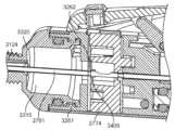
도 4c 및 도 4d는 각각 라인 C-C 및 D-D를 따라 취한 도 4a 및 도 4b의 디바이스의 단면도를 도시하고 있다.
도 4e 내지 도 4g는 도 4a 및 도 4b의 디바이스의 회전 캠의 다양한 도면을 도시하고 있다.
도 4h 내지 도 4o는 도 4a 및 도 4b의 디바이스의 다양한 구성요소의 부가의 도면이다.
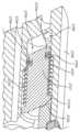
도 4p는 펌핑 챔버로의 재료 유동을 제어하는 일방향 밸브의 다른 도면이다.
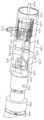
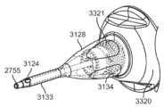
도 5a는 세장형 부재를 갖는 미세 수술 도구의 사시도를 도시하고 있다.
도 5b는 서로로부터 분리된 미세 수술 기구의 구현예의 영구 부분 및 일회용 부분의 사시도를 도시하고 있다.
도 5c는 도 5b의 기구의 영구 부분의 부분도를 도시하고 있다.
도 5d는 원 C-C에서 취한 도 5c의 영구 부분의 상세도를 도시하고 있다.
도 5e 내지 도 5h는 도 5b의 영구 부분과 일회용 부분 사이의 결합의 다양한 도면이다.
도 6a 내지 도 6d는 도 5b의 기구의 선택 가능한 진공 설정을 도시하고 있다.
도 7a 내지 도 7h는 미세 수술 기구의 다양한 도면을 도시하고 있다.
도 8a 내지 도 8d는 도 7a 내지 도 7h의 미세 수술 기구의 캠 메커니즘을 도시하고 있다.
도 8e는 캠 표면 상의 피스톤 운동을 개략적으로 도시하고 있다.
도 8f 내지 도 8h는 다른 캠 표면 상의 피스톤 운동을 개략적으로 도시하고 있다.
도 9a 내지 도 9c는 미세 수술 기구의 구현예의 다양한 도면을 도시하고 있다.
도 10a 내지 도 10c는 도 9a 내지 도 9c의 미세 수술 기구의 구현예의 다양한 도면을 도시하고 있다.
도 11a 및 도 11b는 도 10a 내지 도 10c의 미세 수술 기구의 다른 구현예의 부분 단면도를 도시하고 있다.
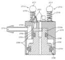
도 12는 조합된 관류 펄스 및 진공 펄스 시스템을 합체하는 펌핑 매니폴드의 개략도이다.
도 13a 내지 도 13c는 세장형 부재를 갖는 미세 수술 도구의 다양한 작동 스테이지를 도시하고 있다.
도 14a 내지 도 14c는 다양한 작동 스테이지에서 도 13a 내지 도 13c의 도구의 부분도를 도시하고 있다.
도 15a 내지 도 15c는 다양한 작동 스테이지에서 도 13a 내지 도 13c의 도구의 부분도를 도시하고 있다.
도 16a 및 도 16b는 다단 트리거에 결합된 통기 메커니즘의 구현예를 도시하고 있다.
도 16c 및 도 16d는 원위 단부 관점으로부터 도 16a 및 도 16b의 통기 메커니즘을 합체하는 가스켓에 의해 커버된 진공 매니폴드를 도시하고 있다.
도 16e 및 도 16f는 투명도의 진공 매니폴드를 통한 근위 단부 관점으로부터 도 16c 및 도 16d의 통기 메커니즘을 도시하고 있다.
도 16g 및 도 16h는 진공 매니폴드가 도시되어 있지 않은 근위 단부 관점으로부터 도 16c 및 도 16d의 통기 메커니즘을 투명도로 도시하고 있다.
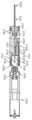
도 17a는 진동 구동 메커니즘의 구현예에 결합된 세장형 부재의 사시도이다.
도 17b 내지 도 17d는 다양한 회전 스테이지에서 도 17a의 진동 메커니즘의 측면도이다.
도 17e 및 도 17f는 각각 신장 및 수축 상태에서 내부 및 외부 튜브를 갖는 세장형 부재의 부분도이다.
도 17g는 완전 원위측 신장 상태에서 세장형 부재의 부분 단면도이다.
도 18a는 종래의 수정체유화 시스템의 세장형 부재의 대칭성, 사인곡선형 모션 프로파일을 도시하고 있다.
도 18b는 세장형 부재의 비대칭성, 비-사인곡선형 모션 프로파일을 도시하고 있다.
도 18c는 신장 속도 프로파일이 세장형 부재의 수축 속도 프로파일과 동일한 세장형 부재에 대한 대칭성 모션 프로파일을 도시하고 있다.
도 18d는 신장 속도 프로파일이 세장형 부재의 수축 속도 프로파일과 상이한 세장형 부재에 대한 비대칭성 모션 프로파일을 도시하고 있다.
도 18e 내지 도 18f는 프로파일이 상이한 세장형 부재의 신장 속도 프로파일 및 수축 속도 프로파일의 부가의 예를 도시하고 있다.
도 18g는 그 신장 속도 프로파일(상부 패널)에 대한 세장형 부재의 원위 팁(하부 패널)의 비-사인곡선형 운동을 도시하고 있다.
도 19a는 진공 프로파일의 구현예를 도시하고 있다.
도 19b 내지 도 19d는 세장형 부재에 대한 비대칭성, 비-사인곡선형 모션 프로파일(실선)과 세장형 부재를 통한 흡인을 위한 진공 프로파일(해칭 라인) 사이의 중첩을 도시하고 있다.
도 19e는 세장형 부재에 대한 비대칭성, 비-사인곡선형 모션 프로파일(실선)과 세장형 부재를 통한 흡인을 위한 진공 프로파일(해칭 라인) 사이의 중첩을 도시하고 있다.
도 19f는 세장형 부재에 대한 비대칭성, 비-사인곡선형 모션 프로파일(실선)과 피스톤 펌프에 의한 세장형 부재를 통한 흡인을 위한 진공 프로파일(해칭 라인) 사이의 중첩을 도시하고 있다.
도 20a는 기구의 하우징 상에 위치된 감아올린 구성의 무균 외장을 도시하고 있다.
도 20b는 기구의 하우징 위에 전개 후에 펼쳐진 구성에서 도 20a의 무균 외장을 도시하고 있다.
도 21은 폐색 후 서지를 방지하도록 구성된 기구의 진공 매니폴드 내의 밸브를 도시하고 있다.
도 22a 내지 도 22d는 폐색 후 서지를 방지하도록 구성된 밸브용 필터의 구현예를 도시하고 있다.
도 23은 무균 패키지에 기구를 포함하는 키트의 구현예를 도시하고 있다.
도면은 단지 예일 뿐이고 실제 축척으로 의도된 것이 아니라는 것이 이해되어야 한다. 본 명세서에 설명된 디바이스는 각각의 도면에 반드시 도시되어 있지는 않은 특징을 포함할 수도 있다는 것이 이해되어야 한다.These and other aspects will now be described in detail with reference to the drawings below. Generally speaking, the drawings are not drawn to scale, either absolutely or relatively, and are intended to be illustrative. Furthermore, the relative arrangement of features and elements may be altered for clarity of illustration.
FIG. 1A is a perspective view of a microsurgical control system according to an embodiment for use with an ophthalmic microsurgical tool.
Figure 1b is a block diagram of the microsurgical control system of Figure 1a.
Figure 1c illustrates stages of operation of the system for throttle position of multidirectional inputs on the mechanism according to an implementation example.
Figure 2 is a schematic diagram of a microsurgical system according to another embodiment.
Figure 3a illustrates an optional secondary waste container for use with the control system.
Figure 3b illustrates fittings for coupling the primary and secondary waste containers to the fluid system.
Figure 3c illustrates an embodiment of a waste container for use with a fluid system.
Figures 3d and 3e illustrate other embodiments of a waste container for use with a fluid system.
FIG. 3f illustrates another embodiment of a waste container for use with a fluid system.
FIGS. 4A and 4B illustrate side views of an embodiment of a microsurgical tool for cutting and aspirating material from an eye configured for use with a microsurgical control system.
Figures 4c and 4d illustrate cross-sectional views of the device of Figures 4a and 4b taken along lines CC and DD, respectively.
FIGS. 4e to 4g illustrate various views of the rotating cam of the device of FIGS. 4a and 4b.
FIGS. 4h through 4o are additional drawings of various components of the device of FIGS. 4a and 4b.
Figure 4p is another drawing of a one-way valve controlling the flow of material into the pumping chamber.
Figure 5a illustrates a perspective view of a microsurgical instrument having an elongated member.
FIG. 5b illustrates a perspective view of the permanent and disposable portions of an embodiment of a microsurgical instrument separated from each other.
Figure 5c illustrates a partial view of a permanent part of the mechanism of Figure 5b.
Fig. 5d shows a detailed view of the permanent portion of Fig. 5c taken from the original CC.
FIGS. 5e to 5h are various views of the joint between the permanent portion and the disposable portion of FIG. 5b.
Figures 6a to 6d illustrate selectable vacuum settings of the apparatus of Figure 5b.
Figures 7a to 7h illustrate various drawings of microsurgical instruments.
Figures 8a to 8d illustrate the cam mechanism of the microsurgical instrument of Figures 7a to 7h.
Figure 8e schematically illustrates the piston movement on the cam surface.
Figures 8f to 8h schematically illustrate piston motion on different cam surfaces.
Figures 9a to 9c illustrate various drawings of embodiments of a microsurgical instrument.
FIGS. 10A to 10C illustrate various drawings of embodiments of the microsurgical instrument of FIGS. 9A to 9C.
FIGS. 11A and 11B illustrate partial cross-sectional views of other embodiments of the microsurgical instrument of FIGS. 10A to 10C.
Figure 12 is a schematic diagram of a pumping manifold incorporating a combined perfusion pulse and vacuum pulse system.
Figures 13a to 13c illustrate various stages of operation of a microsurgical tool having an elongated member.
Figures 14a to 14c illustrate partial views of the tool of Figures 13a to 13c at various stages of operation.
Figures 15a to 15c illustrate partial views of the tool of Figures 13a to 13c at various stages of operation.
Figures 16a and 16b illustrate examples of implementations of a ventilation mechanism coupled to a multi-stage trigger.
Figures 16c and 16d illustrate a vacuum manifold covered by a gasket incorporating the venting mechanisms of Figures 16a and 16b from a distal end perspective.
Figures 16e and 16f illustrate the ventilation mechanism of Figures 16c and 16d from a proximal end perspective through a vacuum manifold of transparency.
Figures 16g and 16h illustrate the ventilation mechanism of Figures 16c and 16d in transparency from a proximal end perspective where the vacuum manifold is not shown.
FIG. 17a is a perspective view of an elongated member incorporated into an embodiment of a vibration drive mechanism.
Figures 17b to 17d are side views of the vibration mechanism of Figure 17a at various rotation stages.
Figures 17e and 17f are partial views of an elongated member having inner and outer tubes in the extended and contracted states, respectively.
Figure 17g is a partial cross-sectional view of the elongated member in a state of full distal extension.
Figure 18a illustrates the symmetric, sinusoidal motion profile of an elongated member of a conventional crystalline emulsification system.
Figure 18b illustrates the asymmetric, non-sinusoidal motion profile of the elongated member.
Figure 18c illustrates a symmetric motion profile for an elongated member where the extension velocity profile is identical to the contraction velocity profile of the elongated member.
Figure 18d illustrates an asymmetric motion profile for an elongated member where the extension velocity profile is different from the contraction velocity profile of the elongated member.
Figures 18e to 18f illustrate additional examples of elongation velocity profiles and shrinkage velocity profiles of elongated members with different profiles.
Figure 18g illustrates the non-sinusoidal motion of the distal tip (lower panel) of the elongated member versus its extension velocity profile (upper panel).
Figure 19a illustrates an example of an implementation of a vacuum profile.
Figures 19b-19d illustrate the overlap between the asymmetric, non-sinusoidal motion profile for the elongated member (solid lines) and the vacuum profile for suction through the elongated member (hatched lines).
Figure 19e illustrates the overlap between the asymmetric, non-sinusoidal motion profile for the elongated member (solid lines) and the vacuum profile for suction through the elongated member (hatched lines).
Figure 19f illustrates the overlap between the asymmetric, non-sinusoidal motion profile for the elongated member (solid line) and the vacuum profile for suction through the elongated member by the piston pump (hatched line).
Figure 20a illustrates a sterile sheath of a rolled configuration positioned on the housing of the device.
Figure 20b illustrates the sterile enclosure of Figure 20a in an unfolded configuration after deployment over the housing of the device.
Figure 21 illustrates a valve within a vacuum manifold of a device configured to prevent surge after occlusion.
Figures 22a to 22d illustrate embodiments of filters for valves configured to prevent surges after occlusion.
Figure 23 illustrates an embodiment of a kit including an instrument in a sterile package.
It should be understood that the drawings are examples only and are not intended to be to scale. It should be understood that the devices described herein may include features that are not necessarily depicted in each drawing.
안내 수술 중에 수정체, 유리체 및 다른 조직의 안내 분쇄 및 제거를 위해 유용한 안과 미세 수술 도구용 시스템, 디바이스 및 방법이 본 명세서에 설명된다. 다양한 시스템, 디바이스 및 방법은, 이에 한정되는 것은 아니지만, 눈 내의 시술 중에 타겟 장소에 존재하는 물질의 절단, 분쇄, 유화, 흡인 및/또는 관류를 포함하는 안과 시술에 유용한 하나 이상의 기능을 수행하도록 구성된다. 본 명세서에서 사용될 때, "물질"은 체액(눈으로부터 또는 눈에 제공된), 수정체 조직, 유리체, 세포와 같은 조직 또는 조직의 조각, 및 눈 내의 시술(예를 들어, 백내장 시술, 유리체 절제 시술 등) 중에 존재할 수도 있는 임의의 다른 유체 또는 조직 또는 다른 물질을 포함할 수 있다. 본 명세서에 설명된 시스템, 디바이스 및 방법은 눈 내의 압력 균형을 유지하기 위해 진공을 인가하고 유체를 전달하도록 구성된다. 진공을 인가하고 그리고/또는 유체를 전달하는 본 명세서에 설명된 시스템, 디바이스 및 방법은 또한 수술 부위 내부 및 부근에서 재료를 절단하고, 분쇄하고, 유화하거나 또는 다른 방식으로 더 작게 만들도록 구성될 수도 있다. 진공이 인가되게 하는 본 명세서에 설명된 시스템, 디바이스 및 방법은 순간적인 역류를 제공하기 위해 산재된 펄스화 양압(positive pressure)이 있거나 없는 펄스화된 진공을 사용하여 그 진공을 제공할 수 있다.Systems, devices, and methods for ophthalmic microsurgical tools useful for intraocular crushing and removal of the lens, vitreous, and other tissues during intraocular surgery are described herein. The various systems, devices, and methods are configured to perform one or more functions useful in ophthalmic procedures, including, but not limited to, cutting, crushing, emulsifying, aspirating, and/or perfusing materials present at a target site during an intraocular procedure. As used herein, “material” may include body fluids (from or provided to the eye), lens tissue, vitreous, tissues or fragments of tissue, such as cells, and any other fluid or tissue or other material that may be present during an intraocular procedure (e.g., a cataract procedure, a vitrectomy procedure, etc.). The systems, devices, and methods described herein are configured to apply a vacuum and deliver a fluid to maintain a pressure balance within the eye. The systems, devices, and methods described herein that apply a vacuum and/or deliver a fluid may also be configured to cut, crush, emulsify, or otherwise make smaller materials within and near the surgical site. The systems, devices and methods described herein for applying a vacuum can provide the vacuum using pulsed vacuum with or without intermittent pulsed positive pressure to provide momentary reversal.
본 명세서에 설명된 디바이스의 다양한 특징 및 기능은 이들이 명시적으로 조합하여 설명되지 않을 수도 있더라도 본 명세서에 설명된 하나 이상의 디바이스에 적용될 수도 있다. 본 명세서에 설명된 디바이스의 다양한 특징 및 기능은, 이들에 한정되는 것은 아니지만 수정체유화 시스템, 유리체 절제 시스템, 백 폴리싱 시스템 및 백내장 수술 또는 유리체 절제 수술 등을 수행하는 데 유용한 다른 도구를 포함하여, 수술 부위 또는 그 부근에서 조직을 절단하고, 분쇄하고, 유화하거나 또는 다른 방식으로 영향을 미치기 위해 또한 유용한 관련 기술분야에 공지된 종래의 디바이스 및 시스템에 적용될 수 있다는 것이 이해되어야 한다.The various features and functions of the devices described herein may be applied to one or more of the devices described herein, even if they are not explicitly described in combination. It should be understood that the various features and functions of the devices described herein may be applied to conventional devices and systems known in the art that are also useful for cutting, pulverizing, emulsifying or otherwise affecting tissue at or near a surgical site, including but not limited to phacoemulsification systems, vitrectomy systems, back polishing systems and other tools useful in performing cataract surgery or vitrectomy surgery.
미세 수술 시스템Microsurgical System
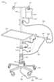
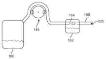
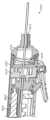
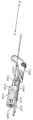
도 1a 및 도 1b는 구현예에 따른 미세 수술 시스템(100)을 도시하고 있다. 미세 수술 시스템(100)은 다양한 안과 수술 절차를 수행하는 데 외과 의사에 의한 사용을 위한 하나 이상의 안과용 미세 수술 기구(225)(본 명세서에서 때때로 "디바이스" 또는 "도구" 또는 "주변 디바이스" 또는 "핸드피스" 또는 "핸드헬드 유닛"이라 칭함)와 함께 사용될 수 있다. 본 명세서에 설명된 미세 수술 기구 및 디바이스 중 임의의 것은 시스템(100)과 동작식으로 결합될 수 있다. 미세 수술 시스템(100)은 폴 조립체(pole assembly)(105)에 결합된 유체 시스템(110)을 포함할 수 있다. 폴 조립체(105) 및 유체 시스템(110)은 각각 전력 시스템(120)에 의해 전력 공급되는 컴퓨팅 유닛(115)에 의해 제어될 수 있다. 유체 시스템(110)은 용기(135) 내의 관류 유체 소스(130), 미세 수술 기구(225)로 이어지는 관류 라인(155), 미세 수술 기구(225)로부터 폐기물 용기(160)를 향해 이어지는 폐기물 라인(165), 및 적어도 하나의 흡인 펌프(145)를 포함할 수 있다. 시스템(100)은 유체 시스템(110)의 관류 라인(155)을 기구(225)의 관류 입구에 결합함으로써 미세 수술 기구(225)에 관류를 제공할 수 있다. 시스템(100)은 또한 유체 시스템(110)의 폐기물 라인(165)을 기구(225)의 폐기물 출구에 결합함으로써 미세 수술 기구(225)를 위한 흡인 압력을 공급할 수 있다. 눈의 수술 필드에 들어가고 나오는 유체의 상대량은 바람직하게는 눈의 전방 챔버가 붕괴되지 않도록 균형화된다. 미세 수술 기구(225)에 제공된 총 관류 체적은 특정 체적 미만, 예를 들어 약 250 mL 미만, 약 200 mL 미만, 약 150 mL 미만, 약 100 mL 미만, 약 50 mL 미만, 약 10 mL 미만으로 유지되는 것이 또한 바람직하다. 미세 수술 시스템(100) 및 미세 수술 기구(225)의 각각의 구성요소는 이하에 더 상세히 설명될 것이다.FIGS. 1A and 1B illustrate a microsurgical system (100) according to an embodiment. The microsurgical system (100) can be used in conjunction with one or more ophthalmic microsurgical instruments (225) (sometimes referred to herein as a “device” or “tool” or “peripheral device” or “handpiece” or “handheld unit”) for use by a surgeon in performing various ophthalmic surgical procedures. Any of the microsurgical instruments and devices described herein can be operatively coupled to the system (100). The microsurgical system (100) can include a fluidic system (110) coupled to a pole assembly (105). The pole assembly (105) and the fluidic system (110) can each be controlled by a computing unit (115) that is powered by a power system (120). The fluid system (110) can include a source of irrigation fluid (130) within a container (135), a irrigation line (155) leading to a microsurgical instrument (225), a waste line (165) leading from the microsurgical instrument (225) toward a waste container (160), and at least one aspiration pump (145). The system (100) can provide irrigation to the microsurgical instrument (225) by coupling the irrigation line (155) of the fluid system (110) to a irrigation inlet of the instrument (225). The system (100) can also provide aspiration pressure for the microsurgical instrument (225) by coupling the waste line (165) of the fluid system (110) to a waste outlet of the instrument (225). The relative amounts of fluid entering and exiting the surgical field of the eye are preferably balanced so as not to collapse the anterior chamber of the eye. It is also desirable that the total perfusion volume provided to the microsurgical instrument (225) be maintained below a certain volume, for example, less than about 250 mL, less than about 200 mL, less than about 150 mL, less than about 100 mL, less than about 50 mL, or less than about 10 mL. Each component of the microsurgical system (100) and the microsurgical instrument (225) will be described in more detail below.
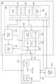
도 1b에 가장 양호하게 도시되어 있는 바와 같이, 시스템(100)의 하나 이상의 구성요소는 컴퓨팅 유닛(115)에 의해 제어될 수 있다. 컴퓨팅 유닛(115)은 제어 프로세서(180), 메모리(190), 통신 모듈(195) 및 하나 이상의 입출력(197)을 포함할 수 있다. 제어 프로세서(180), 메모리(190), 통신 모듈(195), 하나 이상의 입출력(197), 저장 디바이스 등과 같은 컴퓨팅 유닛(115)의 구성요소는 시스템 버스(185)를 통해 상호 접속될 수 있다. 제어 프로세서(180)는 시스템(100)에 결합된 폴 조립체(105), 유체 시스템(110) 및 미세 수술 기구(225) 중 하나 이상과 동작식으로 통신할 수 있다. 제어 프로세서(180)는 또한 하나 이상의 외부 컴퓨팅 디바이스(200)와 동작식으로 통신할 수 있다. 외부 컴퓨팅 디바이스(200)는 이들에 한정되는 것은 아니지만, 데스크탑 컴퓨터, 랩탑 컴퓨터, 태블릿 컴퓨터, 스마트폰, 또는 사용자 입력을 통신하고 수신하는 것이 가능한 다른 디바이스를 포함하여, 다양할 수 있다. 메모리(190)는 사용자 입력 데이터를 수신하고 저장하기 위해 구성된다. 메모리(190)는 데이터를 저장하고 그 데이터를 제어 프로세서(180)와 같은 시스템(100)의 하나 이상의 다른 구성요소에 통신하는 것이 가능한 임의의 유형의 메모리일 수 있다. 메모리(190)는 플래시 메모리, SRAM, ROM, DRAM, RAM, EPROM, 동적 저장 장치 등 중 하나 이상일 수도 있다. 메모리(190)는 기구(225)의 의도된 사용에 관한 하나 이상의 사용자 정의 프로파일을 저장하도록 구성될 수 있다. 메모리(190)는 사용자 정보, 사용 이력, 수행된 측정 등을 저장하도록 구성될 수 있다.As best illustrated in FIG. 1B, one or more components of the system (100) may be controlled by a computing unit (115). The computing unit (115) may include a control processor (180), a memory (190), a communication module (195), and one or more input/output (197) devices. Components of the computing unit (115), such as the control processor (180), the memory (190), the communication module (195), the one or more input/output (197), the storage device, etc., may be interconnected via a system bus (185). The control processor (180) may be in operative communication with one or more of the pole assembly (105), the fluid system (110), and the microsurgical instrument (225) coupled to the system (100). The control processor (180) may also be in operative communication with one or more external computing devices (200). The external computing device (200) may be, but is not limited to, a desktop computer, a laptop computer, a tablet computer, a smart phone, or any other device capable of communicating and receiving user input. The memory (190) is configured to receive and store user input data. The memory (190) may be any type of memory capable of storing data and communicating the data to one or more other components of the system (100), such as the control processor (180). The memory (190) may be one or more of flash memory, SRAM, ROM, DRAM, RAM, EPROM, dynamic storage, and the like. The memory (190) may be configured to store one or more user-defined profiles regarding the intended use of the instrument (225). The memory (190) may be configured to store user information, usage history, measurements performed, and the like.
컴퓨팅 유닛(115)의 통신 모듈(195)은 제어 프로세서(180)와 같은 시스템(100)의 하나 이상의 구성요소, 뿐만 아니라 하나 이상의 외부 컴퓨팅 디바이스(200) 및 미세 수술 기구(225)와 같은 하나 이상의 주변 디바이스와 동작식으로 통신할 수 있다. 컴퓨팅 유닛(115)의 통신 모듈(195)과 외부 컴퓨팅 디바이스(200) 또는 미세 수술 기구(225) 사이의 접속은 RS22 접속, USB, 파이어와이어 접속, 독점 접속, 또는 임의의 외부 컴퓨팅 디바이스(200) 및/또는 미세 수술 기구(225)에 정보를 수신 및/또는 송신하도록 구성된 임의의 다른 적합한 유형의 유선 접속과 같은 유선 통신 포트를 포함할 수 있다. 통신 모듈(195)은 예를 들어 시스템(100)의 동작 및/또는 미세 수술 기구(225)의 제어 프로그래밍에 대한 정보를 외부 컴퓨팅 디바이스(200) 상에 실시간으로 디스플레이하기 위해 정보가 무선 링크를 통해 컴퓨팅 유닛(115)과 외부 컴퓨팅 디바이스(200) 및/또는 미세 수술 기구(225) 사이에 공급될 수 있도록 하는 무선 통신 포트를 또한 포함할 수 있다. 예를 들어, 기구(225)가 시스템(100)에 독립적으로 동작되면, 외부 컴퓨팅 디바이스(200)는 미세 수술 기구(225)와 직접 통신할 수 있다는 것이 이해되어야 한다. 시스템(100)에 대한 임의의 다양한 조정 및 프로그래밍은 외부 컴퓨팅 디바이스(200)를 사용하여 수행될 수 있다. 무선 접속은 블루투스(Bluetooth), 와이파이(Wi-Fi), 무선 주파수, 지그비(ZigBee) 통신 프로토콜, 적외선 또는 휴대폰 시스템과 같은 임의의 적합한 무선 시스템을 사용할 수 있고, 또한 수신된 정보의 출처를 검증하기 위해 코딩 또는 인증을 채용할 수 있다. 무선 접속은 임의의 다양한 독점 무선 접속 프로토콜일 수도 있다.The communication module (195) of the computing unit (115) can operatively communicate with one or more components of the system (100), such as the control processor (180), as well as one or more peripheral devices, such as one or more external computing devices (200) and a microsurgical instrument (225). The connection between the communication module (195) of the computing unit (115) and the external computing device (200) or microsurgical instrument (225) can include a wired communication port, such as an RS22 connection, a USB, a Firewire connection, a proprietary connection, or any other suitable type of wired connection configured to receive and/or transmit information to any of the external computing devices (200) and/or microsurgical instrument (225). The communication module (195) may also include a wireless communications port to allow information to be supplied between the computing unit (115) and the external computing device (200) and/or the microsurgical instrument (225) via a wireless link, for example to display information regarding the operation of the system (100) and/or the control programming of the microsurgical instrument (225) in real time on the external computing device (200). It should be appreciated that, for example, if the instrument (225) is operated independently of the system (100), the external computing device (200) may communicate directly with the microsurgical instrument (225). Any of a variety of adjustments and programming for the system (100) may be performed using the external computing device (200). The wireless connection may use any suitable wireless system, such as Bluetooth, Wi-Fi, radio frequency, ZigBee communication protocols, infrared, or a cellular system, and may also employ coding or authentication to verify the source of the information received. The wireless connection may be any of a variety of proprietary wireless access protocols.
제어 프로세서(180)는 시스템(100) 내에서 실행을 위한 명령을 처리하는 것이 가능할 수 있다. 이러한 실행된 명령은 시스템(100)과 동작식으로 통신하는 시스템 또는 주변 디바이스의 사용과 관련하여 본 명세서에 설명된 프로세스 중 하나 이상을 구현할 수 있다. 제어 프로세서(180)는 단일-스레드(single-threaded) 프로세서 또는 멀티 스레드 프로세서일 수 있다. 제어 프로세서(180)는 시스템(100)의 동작에 대한 정보의 출력을 사용자에게 제공하기 위해 메모리(190) 내에 및/또는 저장 디바이스 상에 저장된 명령을 처리하는 것이 가능할 수 있다. 제어 프로세서(180)는 시스템(100) 뿐만 아니라 시스템(100)에 결합된 미세 수술 기구(225)의 하나 이상의 양태에 대한 제한을 조정하거나 제공하도록 프로그래밍되는 것이 가능한 소프트웨어를 포함할 수 있다. 제어 프로세서(180)에 의해 실행되는 소프트웨어는 사용 중에 임의의 사용자 입력 없이 시스템(100) 또는 시스템(100)에 접속된 미세 수술 기구의 특정 양태를 제공할 수 있다. 구현예에서, 조정 또는 프로그래밍은 시스템(100) 내에서 또는 외부 컴퓨터 디바이스(200) 상에서 소프트웨어에 의해 제어되는 제어 프로세서(180)를 통해 이루어질 수 있다. 사용자는 블루투스와 같은 무선 접속을 통해 시스템(100)과 통신하는 외부 컴퓨팅 디바이스(200)를 통해 원격으로 제어기(180)를 프로그래밍할 수 있다. 관류 소스(130)의 높이, 폐기물 용기(160)의 높이, 펌프(145)의 속도 등을 포함하여, 이하에 상세히 설명될 시스템(100)의 하나 이상의 양태가 프로그래밍될 수 있다. 기구(225)는 기구의 하나 이상의 구성요소(예를 들어, 구동 메커니즘, 진공 소스 또는 기구의 다른 구성요소)와 동작식으로 통신하는 제어 프로세서, 메모리 및/또는 통신 모듈을 포함하는 컴퓨팅 유닛을 또한 포함할 수 있다. 맥동성 흡인의 속도, 진동 기계 팁의 속도, 최대 속도의 제한, 다양한 모드(즉, 펄스화 모드 또는 버스트 모드)의 디스에이블(disable)/인에이블(enable), 모드의 파라미터(즉, 펄스 모드 중에 온 타임 대 오프 타임) 조정, 및 본 명세서의 다른 곳에서 설명된 바와 같은 기구(225)의 다양한 다른 제어 가능한 파라미터를 포함하여, 또한 이하에 상세히 설명될 미세 수술 기구(225)의 하나 이상의 양태가 프로그래밍될 수 있다. 사용자는 또한 이하에 더 상세히 설명되는 바와 같이 시스템(100)을 통하지 않고 직접 기구(225)와 통신하는 외부 컴퓨팅 디바이스(200)를 사용하여 미세 수술 기구(225)를 프로그래밍할 수 있다.The control processor (180) may be capable of processing instructions for execution within the system (100). Such executed instructions may implement one or more of the processes described herein in connection with the use of a system or peripheral device in operative communication with the system (100). The control processor (180) may be a single-threaded processor or a multi-threaded processor. The control processor (180) may be capable of processing instructions stored within the memory (190) and/or on a storage device to provide output of information about the operation of the system (100) to a user. The control processor (180) may include software that may be programmed to adjust or provide constraints on one or more aspects of the system (100) as well as a microsurgical instrument (225) coupled to the system (100). The software executed by the control processor (180) may provide certain aspects of the system (100) or a microsurgical instrument coupled to the system (100) without any user input during use. In an embodiment, the adjustment or programming may be accomplished via a control processor (180) that is software controlled within the system (100) or on an external computer device (200). A user may program the controller (180) remotely via an external computing device (200) that communicates with the system (100) via a wireless connection, such as Bluetooth. One or more aspects of the system (100), including the height of the perfusion source (130), the height of the waste container (160), the speed of the pump (145), etc., as will be described in detail below, may be programmed. The apparatus (225) may also include a computing unit including a control processor, memory, and/or communication modules that are in operative communication with one or more components of the apparatus (e.g., a drive mechanism, a vacuum source, or other components of the apparatus). One or more aspects of the microsurgical instrument (225) may also be programmed, including the speed of the pulsating suction, the speed of the vibrating machine tip, limiting the maximum speed, disabling/enabling various modes (i.e., pulsed mode or burst mode), adjusting parameters of the modes (i.e., on time versus off time during pulse mode), and various other controllable parameters of the instrument (225) as described elsewhere herein. A user may also program the microsurgical instrument (225) using an external computing device (200) that communicates directly with the instrument (225) rather than through the system (100), as described in more detail below.
기구(225) 및/또는 시스템(100)은 또한 입력의 작동시에 특정 작용에 대한 제한을 제공하도록 프로그래밍될 수 있다. 예를 들어, 기구(225)의 구동 메커니즘은 입력의 작동시에 최소 및/또는 최대 속도를 갖도록 프로그래밍될 수 있고, 또는 유체 주입 및 흡인의 경우에 기구(225)는 입력의 작동시에 최소 및/또는 최대 유체 압력을 갖도록 프로그래밍될 수 있다. 따라서, 본 명세서에 설명된 기구(225)는 사용자에 의해 뿐만 아니라 입력의 작동시에 기구(225)의 하나 이상의 양태에 영향을 미치는 미리 프로그래밍된 명령에 의해 조정 가능한 입력을 사용하여 프로그래밍될 수 있다.The device (225) and/or the system (100) may also be programmed to provide limitations on certain actions upon actuation of an input. For example, the drive mechanism of the device (225) may be programmed to have a minimum and/or maximum speed upon actuation of an input, or, in the case of fluid injection and aspiration, the device (225) may be programmed to have a minimum and/or maximum fluid pressure upon actuation of an input. Accordingly, the device (225) described herein may be programmed using inputs that are adjustable by a user as well as by preprogrammed commands that affect one or more aspects of the device (225) upon actuation of an input.
언급된 바와 같이, 시스템(100)의(또는 기구(225)의) 컴퓨팅 유닛(115)은 예로서 외부 컴퓨팅 디바이스(200)를 통해 원격으로 제어되고, 조정되고 그리고/또는 프로그래밍될 수 있다. 시스템(100)의 컴퓨팅 유닛(115)은 또한 시스템(100) 상의 하나 이상의 입력(197) 뿐만 아니라 기구(225) 상의 하나 이상의 입력(228)을 통해 직접 제어되고, 조정되고 그리고/또는 프로그래밍될 수 있다. 따라서, 본 명세서에 설명된 디바이스는 하나 이상의 양태가 사용자에 의한 수동 입력에 따라 수동으로 제어되고 그리고/또는 조정되거나 또는 하나 이상의 양태를 제어하도록 프로그래밍되도록 사용될 수 있다. 제어기는 디바이스의 하나 이상의 양태에 대한 제한을 조정하거나 제공하도록 프로그래밍되는 것이 가능한 소프트웨어를 포함할 수 있다. 따라서, 제어기에 의해 실행되는 소프트웨어는 사용 중에 임의의 사용자 입력 없이 디바이스의 특정 양태를 제공할 수 있다. 구현예에서, 조정 또는 프로그래밍은 디바이스 내에서 또는 직접 또는 시스템(100)을 통해 디바이스와 동작식으로 통신하는 외부 컴퓨터 디바이스(200) 상에서, 소프트웨어에 의해 제어되는 제어기를 통해 이루어질 수 있다. 사용자는 블루투스와 같은 무선 접속을 통해 디바이스와 통신하는 외부 컴퓨팅 디바이스를 통해 원격으로 제어기를 프로그래밍할 수 있다.As mentioned, the computing unit (115) of the system (100) (or of the device (225)) may be remotely controlled, adjusted, and/or programmed, for example, via an external computing device (200). The computing unit (115) of the system (100) may also be directly controlled, adjusted, and/or programmed via one or more inputs (197) on the system (100) as well as one or more inputs (228) on the device (225). Accordingly, the devices described herein may be used such that one or more aspects are manually controlled and/or adjusted based on manual input by a user, or may be programmed to control one or more aspects. The controller may include software that is capable of being programmed to adjust or provide constraints on one or more aspects of the device. Thus, software executed by the controller may provide certain aspects of the device without any user input during use. In an embodiment, the adjustment or programming may be accomplished via a software-controlled controller within the device or on an external computer device (200) that operatively communicates with the device either directly or through the system (100). A user may program the controller remotely via an external computing device that communicates with the device via a wireless connection, such as Bluetooth.
시스템(100)의 입력(197)은 하나 이상의 트리거, 버튼, 슬라이더, 다이얼, 키패드, 스위치, 터치스크린, 풋 페달, 또는 시스템(100)의 응답을 활성화하고, 수정하거나, 또는 다른 방식으로 야기하도록 수축되고, 가압되고, 압착되고, 활주하고, 탭핑되거나, 또는 다른 방식으로 작동될 수 있는 다른 입력을 포함할 수 있다. 몇몇 구현예에서, 하나 이상의 입력(197)은 시스템(100) 뿐만 아니라 시스템(100)과 동작식으로 통신하는 주변 디바이스의 하나 이상의 구성요소를 제어하고, 조정하고 그리고/또는 프로그래밍하기 위한 음성 명령을 수신하도록 구성된 마이크로폰(198)을 포함한다. 시스템의 입력(197)은 미세 수술 기구(225) 상의 하나 이상의 입력(228)과 별개이고 그에 추가될 수 있는데, 이는 이하에 더 상세히 설명될 것이다.The inputs (197) of the system (100) may include one or more triggers, buttons, sliders, dials, keypads, switches, touchscreens, foot pedals, or other inputs that can be compressed, pressed, squeezed, slid, tapped, or otherwise actuated to activate, modify, or otherwise cause a response of the system (100). In some implementations, the one or more inputs (197) include a microphone (198) configured to receive voice commands to control, adjust, and/or program one or more components of the system (100) as well as peripheral devices that are in operative communication with the system (100). The inputs (197) of the system may be separate from and in addition to the one or more inputs (228) on the microsurgical instrument (225), which will be described in more detail below.
다시 도 1a 및 도 1b와 관하여, 폴 조립체(105), 유체 시스템(110), 컴퓨팅 유닛(115), 뿐만 아니라 미세 수술 기구(225) 또는 시스템(100)에 연결된 다른 주변 디바이스 중 하나 이상은 전력 시스템(120)에 의해 전력 공급될 수 있다. 예를 들어, 전력 시스템(120)은 예로서 모터 또는 다른 전동식 메커니즘으로 베이스(134)에 대해 폴(132)을 신축식으로 조정함으로써 관류 소스(130)의 높이를 조정하기 위해 폴 조립체(105)에 전력을 제공할 수 있다. 전력 시스템(120)은 유체 시스템(110)의 흡인 펌프(145) 뿐만 아니라 관류 라인(155)을 향한 유체 유동을 제어하도록 구성된 하나 이상의 밸브(150)에 전력을 제공할 수 있다. 전력 시스템(120)은 또한 시스템(100)과 동작식으로 통신하는 미세 수술 기구(225)와 같은 임의의 주변 디바이스에 전력을 제공할 수 있다. 전력 시스템(120)은 코드(168) 및 플러그(170)를 갖는 전원 콘센트(166)를 포함할 수 있다. 플러그(170)는 전력 시스템(120)에 전력을 제공하기 위해 벽 소켓 내에 삽입되도록 구성된다. 전력 시스템(120)은 미세 수술 기구 전원(227)의 플러그(270)와 같은 하나 이상의 주변 디바이스의 플러그를 수용하도록 구성된 하나 이상의 소켓(175)을 추가로 포함할 수 있다. 미세 수술 기구(225)의 전원(227)은 시스템(100)의 전력 시스템(120)의 소켓(175) 중 하나 내에 플러깅될 수 있다. 폴 조립체(105)는 또한 기구가 그 자신의 전원(227)을 포함할 필요가 없고 폴 조립체(105) 내에 직접 플러깅될 수 있도록 기구의 전원(227)을 합체할 수 있다.Referring again to FIGS. 1A and 1B , the pole assembly (105), the fluid system (110), the computing unit (115), as well as one or more of the microsurgical instrument (225) or other peripheral devices connected to the system (100) may be powered by the power system (120). For example, the power system (120) may provide power to the pole assembly (105) to adjust the height of the perfusion source (130) by, for example, telescopically adjusting the pole (132) relative to the base (134) by a motor or other powered mechanism. The power system (120) may provide power to the suction pump (145) of the fluid system (110), as well as one or more valves (150) configured to control the flow of fluid toward the perfusion line (155). The power system (120) may also provide power to any peripheral devices, such as the microsurgical instrument (225), that are in operative communication with the system (100). The power system (120) may include a power outlet (166) having a cord (168) and a plug (170). The plug (170) is configured to be inserted into a wall socket to provide power to the power system (120). The power system (120) may further include one or more sockets (175) configured to accept plugs of one or more peripheral devices, such as a plug (270) of a microsurgical instrument power source (227). The power source (227) of the microsurgical instrument (225) may be plugged into one of the sockets (175) of the power system (120) of the system (100). The pole assembly (105) may also incorporate a power source (227) of the instrument such that the instrument need not include its own power source (227) and may be plugged directly into the pole assembly (105).
폴 조립체(105)는 정맥내(IV) 폴에 통상적인 하나 이상의 특징을 포함할 수 있다. 폴 조립체(105)는 하나 이상의 행거(131)의 높이가 조정될 수 있도록 베이스(134)에 대해 이동 가능하도록 구성된 신축식 폴(132)을 포함할 수 있다. 행거(131)는 관류 소스(130)와 미세 수술 기구(225) 사이의 관류 라인(155) 내에 적절한 유체 압력을 생성하도록 계산된 높이에서 유체 시스템(110)의 하나 이상의 관류 용기(135) 내에 포함된 관류 유체 소스(130)를 현수하도록 구성된다. 관류 소스(130)는 폴 조립체(105)의 행거(131)에 의해 환자의 레벨 위에 현수될 수 있고 관류 라인(155)은 관류 소스(130)의 하단 영역에 결합될 수 있다.The pole assembly (105) may include one or more features typical of an intravenous (IV) pole. The pole assembly (105) may include a telescoping pole (132) configured to be movable relative to a base (134) such that the height of one or more hangers (131) may be adjusted. The hangers (131) are configured to suspend a perfusion fluid source (130) contained within one or more perfusion vessels (135) of the fluid system (110) at a height calculated to create an appropriate fluid pressure within the perfusion line (155) between the perfusion source (130) and the microsurgical instrument (225). The perfusion source (130) may be suspended above the level of the patient by the hangers (131) of the pole assembly (105) and the perfusion line (155) may be coupled to a lower region of the perfusion source (130).
폴 조립체(105)는 하나 이상의 행거(131)의 높이를 조정하여 이에 의해 관류 유체 압력을 변경하고 이에 대응하여 입구 라인 내의 유체의 유량을 변경하도록 구성된 하나 이상의 버튼, 레버, 풋 페달, 또는 다른 액추에이터를 합체할 수 있다. 하나 이상의 행거(131)의 높이는 수동으로 및/또는 전동식 조정을 통해 조정될 수 있다. 예를 들어, 폴 조립체(105)는 베이스(134)에 대해 신축식 폴(132)을 이동시키도록 구성된 전동식 시스템을 포함할 수 있다. 폴 조립체(105)는 컴퓨팅 유닛(115)과 동작식으로 통신할 수 있어서, 전동식 조정이 시술 중에 유체 요구에 따라 자동이 될 수 있게 되는데, 이는 이하에 더 상세히 설명될 것이다. 폴 조립체(105)의 베이스(134)는 폴 조립체(105)의 완전한 이동성을 보장하기 위해 복수의 회전 캐스터(140)를 가질 수 있다. 캐스터(140)는 사용 중에 부주의한 이동을 방지하기 위해 관련 기술분야에 공지된 바와 같이 잠금될 수 있다. 폴 조립체(105)는 조정 가능 수술 트레이 또는 선반 또는 다른 저장 부위 뿐만 아니라 하나 이상의 클램프, 핀치 밸브, 배관 루프, 클립 등과 같은 하나 이상의 다른 사용자 특징부를 포함할 수 있다. 몇몇 구현예에서, 폴 조립체(105)는 통합형 수술 기구 트레이(133), 예를 들어 폴(132)에 클램핑된 트레이(133)를 포함할 수 있다(도 1a 참조).The pole assembly (105) may incorporate one or more buttons, levers, foot pedals, or other actuators configured to adjust the height of one or more hangers (131) to thereby change the perfusion fluid pressure and thereby change the flow rate of fluid within the inlet line. The height of one or more hangers (131) may be adjusted manually and/or via powered adjustment. For example, the pole assembly (105) may include a powered system configured to move a telescopic pole (132) relative to the base (134). The pole assembly (105) may be in operative communication with the computing unit (115) such that the powered adjustment may be automated during a procedure depending on the fluid needs, as will be described in more detail below. The base (134) of the pole assembly (105) may have a plurality of swivel casters (140) to ensure full mobility of the pole assembly (105). The casters (140) may be lockable as is known in the art to prevent inadvertent movement during use. The pole assembly (105) may include one or more other user features, such as an adjustable surgical tray or shelf or other storage area, as well as one or more clamps, pinch valves, tubing loops, clips, and the like. In some implementations, the pole assembly (105) may include an integrated surgical instrument tray (133), for example a tray (133) clamped to the pole (132) (see FIG. 1A ).
여전히 도 1a 및 도 1b와 관련하여 그리고 전술된 바와 같이, 유체 시스템(110)은 관류 유체 소스(130), 관류 라인(155), 폐기물 라인(165), 폐기물 용기(160) 및 적어도 하나의 흡인 펌프(145)를 포함할 수 있다. 흡인 펌프(145)는 눈으로부터 내부 루멘을 향해 수정체 물질을 흡인하기 위해 펌프(145)로부터 세장형 부재의 내부 루멘으로 배경 흡인을 전달하도록 구성된 유체 라인에 유동적으로 결합될 수 있다. 유체 시스템(110)은 관류 유체 소스(130)로부터 관류 유체를 전달하도록 구성된 관류 유체 펌프를 선택적으로 포함할 수도 있다. 관류 유체는 관류 유체 소스(130)를 나와 관류 유체 라인(155)을 통해 미세 수술 기구(225)를 향해 진행할 수도 있다. 치료 부위 부근의 선택적 관류 유체 저장조가 마찬가지로 합체될 수도 있다. 예를 들어, 관류 유체 저장조는 유체에 대한 수요를 순간적으로 충족시키기 위해 미세 수술 기구(225)의 원위 단부 내에 위치될 수도 있는데, 이는 이하에 더 상세히 설명될 것이다.Still with respect to FIGS. 1A and 1B and as described above, the fluid system (110) may include a perfusion fluid source (130), a perfusion line (155), a waste line (165), a waste container (160), and at least one aspiration pump (145). The aspiration pump (145) may be fluidly coupled to a fluid line configured to deliver background aspiration from the pump (145) to the inner lumen of the elongated member to aspirate lens material from the eye toward the inner lumen. The fluid system (110) may optionally include a perfusion fluid pump configured to deliver perfusion fluid from the perfusion fluid source (130). The perfusion fluid may be routed from the perfusion fluid source (130) through the perfusion fluid line (155) toward the microsurgical instrument (225). An optional perfusion fluid reservoir proximal to the treatment site may likewise be incorporated. For example, a perfusion fluid reservoir may be positioned within the distal end of the microsurgical instrument (225) to meet the demand for fluid on an instantaneous basis, as will be described in more detail below.
관류 유체 소스(130), 기구(225) 및/또는 관류 라인(155)은 직접 또는 관류 포트를 통해 기구(225)에 유동적으로 결합된 관류 라인(155)을 통한 유체 유동의 부가의 제어를 제공하도록 구성된 하나 이상의 밸브(150) 및/또는 센서를 선택적으로 포함할 수도 있다. 하나 이상의 밸브(150)는 관류 라인(155)을 단단히 핀칭하여 이에 의해 미세 수술 기구(225)를 향한 유체 유동을 방지하거나 밸브(150)의 개방시에 관류 소스(130)로부터 미세 수술 기구(225)를 향한 완전한 유체 유동을 허용하도록 구성된 핀치 밸브 또는 핀치 클램프일 수 있다.The perfusion fluid source (130), the instrument (225) and/or the perfusion line (155) may optionally include one or more valves (150) and/or sensors configured to provide additional control of fluid flow through the perfusion line (155) fluidly coupled to the instrument (225) either directly or through a perfusion port. The one or more valves (150) may be pinch valves or pinch clamps configured to tightly pinch the perfusion line (155) thereby preventing fluid flow toward the microsurgical instrument (225) or to allow full fluid flow from the perfusion source (130) toward the microsurgical instrument (225) upon opening of the valve (150).
밸브(150)는 관련 기술분야에 공지된 바와 같이 수동으로 개폐될 수 있다. 밸브(150)는 대안적으로 또는 부가적으로 컴퓨팅 유닛(115)에 의한 입력시에, 예를 들어, 이하에 더 상세히 설명되는 바와 같이 미세 수술 기구(225)의 작동시에 작동될 수 있다. 다른 밸브 및 클램프 유형이 여기에서 고려된다. 기구(225) 및/또는 폐기물 라인(165)(본 명세서에서 흡인 라인이라 칭할 수도 있음)은 기구(225)로부터의 유체 유동의 부가의 제어를 제공하도록 구성된 하나 이상의 밸브 및/또는 센서를 선택적으로 포함할 수도 있다. 하나 이상의 밸브(150)는 신축식 폴(132) 부근의 영역 내에 통합될 수 있고, 여기서, 관류 소스(130)는 밸브(150)가 관류 라인(155)을 통한 유동을 제어할 수 있도록 매달려 있다.The valve (150) may be manually opened and closed as is known in the art. The valve (150) may alternatively or additionally be actuated upon input by the computing unit (115), for example, upon operation of the microsurgical instrument (225), as described in more detail below. Other valve and clamp types are contemplated herein. The instrument (225) and/or the waste line (165) (which may also be referred to herein as a suction line) may optionally include one or more valves and/or sensors configured to provide additional control of the fluid flow from the instrument (225). One or more valves (150) may be integrated within an area adjacent the telescoping pole (132), wherein the perfusion source (130) is suspended such that the valve (150) controls the flow through the perfusion line (155).
관류 소스(130)는 예를 들어 밸브(150)를 개방할 때 미세 수술 기구(225)를 향한 관류 소스(130)로부터 유체 유동을 야기하도록 양압 구배를 제공하는 눈의 레벨 위에 위치될 수 있다. 개방 밸브(150)는 미세 수술 기구(225)가 예를 들어 관류 슬리브(예를 들어, 도 9b에 도시되어 있는 관류 슬리브(3128) 참조) 외부로 관류 유체를 전달할 준비가 되도록 임의의 "사체적" 또는 "서지 체적"을 제거하는 관류 유체로 라인(155)을 프라이밍한다. 이하에 설명되는 바와 같이, 관류 유체는 일반적으로 흡인 시스템의 밸브가 개방될 때까지 기구(225)의 슬리브의 개구로 유출하지 않을 것이다. 상승된 관류 소스(130)로부터의 정수압은 일반적으로, 모터가 턴오프될 때 폐쇄 위치에 남아 있고 특정 압력차에 도달할 때 개방되는 핸드헬드 부분의 진공 시스템 내의 하나 이상의 밸브의 균열 압력보다 작다. 관류는 눈을 향해 수동적으로 공급될 수 있고, 폐기물 라인의 개폐는 관류 유체가 개구 외부로 그리고 눈 내로 유동하는지 여부 및 시기를 지시할 수 있다.The perfusion source (130) can be positioned above the level of the eye to provide a positive pressure gradient to cause a flow of fluid from the perfusion source (130) toward the microsurgical instrument (225) when, for example, the valve (150) is opened. The opening valve (150) primes the line (155) with perfusion fluid to remove any “dead volume” or “surge volume” so that the microsurgical instrument (225) is ready to deliver perfusion fluid out of, for example, a perfusion sleeve (see, for example, perfusion sleeve (3128) illustrated in FIG. 9B ). As described below, the perfusion fluid will generally not flow out of the opening in the sleeve of the instrument (225) until the valve of the aspiration system is opened. The hydrostatic pressure from the elevated perfusion source (130) is generally less than the cracking pressure of one or more valves within the vacuum system of the handheld portion that remain in the closed position when the motor is turned off and open when a certain pressure differential is reached. Irrigation can be passively supplied to the eye, and opening and closing of the waste line can dictate whether and when irrigation fluid flows out of the opening and into the eye.
유체 헤드 압력은 눈에 대한 관류 소스(130)의 높이에 의존한다. 관류 소스(130)의 높이가 치료 부위에 비해 증가함에 따라, 관류 라인(155)을 통한 유체 압력이 더 커진다. 관류 소스(130)의 높이가 치료 부위에 비해 감소함에 따라, 관류 라인(155)을 통한 유체 압력이 더 낮아진다. 치료 부위로부터 이격하여 유체를 인출하는(예를 들어, 시스템의 흡인 펌프(145)를 통해) 흡인 압력은 폐기물 용기(160)의 상대 높이에 의해 영향을 받을 수 있다. 폐기물 용기(160)는 분위기 압력 이하로 설정될 수 있다. 폐기물 용기(160)가 치료 부위에 비해 낮을수록, 압력차가 커지고 잠재적인 사이펀 압력이 커진다. 예를 들어, 폐기물 용기(160)는 눈으로부터 폐기물 용기(160)를 향한 유체 및 물질의 유동을 야기하는 환자의 레벨 아래에 위치될 수 있다. 폐기물 용기(160)를 환자의 레벨 아래로 더 낮추는 것은 더 큰 압력차를 야기한다.The fluid head pressure depends on the elevation of the perfusion source (130) relative to the eye. As the elevation of the perfusion source (130) increases relative to the treatment site, the fluid pressure through the perfusion line (155) increases. As the elevation of the perfusion source (130) decreases relative to the treatment site, the fluid pressure through the perfusion line (155) decreases. The aspiration pressure to withdraw fluid away from the treatment site (e.g., via the aspiration pump (145) of the system) can be affected by the relative elevation of the waste container (160). The waste container (160) can be set below ambient pressure. The lower the waste container (160) is relative to the treatment site, the greater the pressure differential and the greater the potential siphon pressure. For example, the waste container (160) can be positioned below the level of the patient, which causes a flow of fluid and material from the eye toward the waste container (160). Lowering the waste container (160) further below the patient's level causes a greater pressure differential.
관류 소스(130) 및 폐기물 용기(160)의 모두의 상대 높이는 수동으로 및/또는 자동으로 조정 가능할 수 있다. 사용자는 폴 조립체(105) 상의 조정 요소에 의한 것과 같이 수동으로 또는 시스템(100)과 통신하는 외부 컴퓨팅 디바이스(200)를 사용하여 높이를 제어할 수 있다. 높이는 또한 시스템(100)의 컴퓨팅 유닛(115)을 통해 자동으로 제어될 수 있다. 시스템(100)의 컴퓨팅 유닛(115)은 예를 들어 더 많은 유체가 치료 부위에서 요구될 때 더 큰 압력차를 제공하기 위해 치료 부위에 대한 관류 소스(130)의 높이를 자동으로 조정할 수 있다. 이 방식으로, 시스템(100)은 전방 챔버와 같은 치료 부위에서 유체 전달 및 유체 후퇴의 적절한 균형을 유지할 수 있다. 예를 들어, 시스템(100)의 사용 중에, 더 많은 유체가 기구(225)를 통해 전달됨에 따라 관류 소스(130) 내의 유체 레벨이 감소할 수 있다. 시스템(100)은 유체 레벨의 변화를 감지하고 관류 소스(130)의 유체 헤드를 유지하기 위해 관류 소스(130)를 자동으로 상승시킬 수 있다(즉, IV 폴 높이를 상승시킴).The relative heights of both the perfusion source (130) and the waste container (160) may be manually and/or automatically adjustable. A user may control the height manually, such as by an adjustment element on the pole assembly (105), or by using an external computing device (200) in communication with the system (100). The height may also be automatically controlled via the computing unit (115) of the system (100). The computing unit (115) of the system (100) may automatically adjust the height of the perfusion source (130) relative to the treatment site to provide a greater pressure differential, for example, when more fluid is required at the treatment site. In this manner, the system (100) may maintain an appropriate balance of fluid delivery and fluid withdrawal at the treatment site, such as the anterior chamber. For example, during use of the system (100), the fluid level within the perfusion source (130) may decrease as more fluid is delivered through the device (225). The system (100) can detect changes in fluid level and automatically raise the perfusion source (130) (i.e., raise the IV pole height) to maintain the fluid head of the perfusion source (130).
시스템(100) 및/또는 미세 수술 기구(225)는 임의의 다양한 방법에 의해 눈의 내외로 이동하는 유체의 상대량을 감지할 수 있다. 몇몇 구현예에서, 폴 조립체(105)는 얼마나 많은 유체가 눈으로 전달되고 있고 얼마나 많은 유체가 제거되고 있는지를 평가하도록 구성된 하나 이상의 센서를 포함할 수 있다. 예를 들어, 관류 소스(130)는 소스(130)에서 유체 체적 및/또는 중량을 평가하도록 구성된 센서에 대해 위치될 수 있다. 다른 구현예에서, 하나 이상의 센서는 예를 들어 비접촉 유체 유동 센서를 사용하여 관류 소스(130)로부터의 유체 유동을 측정할 수 있다. 유사하게, 폐기물 용기(160)는 폐기물 용기(160) 내로의 유체 체적, 유체 중량 및/또는 유체 유동을 평가하도록 구성된 센서에 대해 위치될 수 있다. 다른 구현예에서, 하나 이상의 센서는 눈 내의 전체 유체 균형을 평가하기 위해 입구 및 출구 라인과 같은 미세 수술 기구(225)에 대해 위치될 수 있다. 적어도 관류측의 센서는 이들에 한정되는 것은 아니지만, 관류 및/또는 폐기물 라인 내의 체적 유량을 측정하도록 구성된 초음파, 레이더, 레이저, 도플러 및 다른 유형의 감지 기술을 포함하는 비접촉 액체 레벨 또는 유체 유동 센서일 수 있다. 센서로부터의 정보는, 예를 들어 기구(225)에 대한 관류 소스(130)의 높이를 증가시킴으로써, 따라서 용기 내의 액체의 감소를 오프셋하도록 유체 헤드를 증가시킴으로써, 유체 균형을 자동으로 조정하기 위해 시스템에 의해 사용될 수 있다.The system (100) and/or the microsurgical instrument (225) can detect the relative amount of fluid moving into and out of the eye by any of a variety of methods. In some implementations, the pole assembly (105) can include one or more sensors configured to assess how much fluid is being delivered into the eye and how much fluid is being removed. For example, the perfusion source (130) can be positioned relative to a sensor configured to assess the volume and/or weight of fluid in the source (130). In other implementations, the one or more sensors can measure the fluid flow from the perfusion source (130), for example, using a non-contact fluid flow sensor. Similarly, the waste container (160) can be positioned relative to a sensor configured to assess the volume, weight, and/or flow of fluid into the waste container (160). In other implementations, one or more sensors can be positioned relative to the microsurgical instrument (225), such as the inlet and outlet lines, to assess the overall fluid balance within the eye. The sensor on the perfusion side, at least, may be a non-contact liquid level or fluid flow sensor, including but not limited to ultrasonic, radar, laser, Doppler and other types of sensing technologies configured to measure volumetric flow within the perfusion and/or waste lines. Information from the sensor may be used by the system to automatically adjust the fluid balance, for example by increasing the height of the perfusion source (130) relative to the device (225), thus increasing the fluid head to offset the decrease in liquid within the vessel.
몇몇 구현예에서, 초음파 센서 또는 임의의 다른 유형의 비접촉 유체 센서는 관류 라인(155) 또는 폐기물 라인(165) 상에 배치된다. 하나 이상의 센서는 배관의 길이를 따른 임의의 장소에 배치될 수도 있다. 몇몇 실시예에서, 센서는 라인(155, 165)이 핸드헬드 기구(225)에 들어가고 나오는 장소에 가깝게 배치된다. 센서는 이들이 다른 혈액 또는 유체 측정 센서와 유사하게 배치되는 장소에서 배관을 통한 유량을 검출할 수 있다. 몇몇 구현예에서, 센서는 핸드헬드 디바이스(225) 내에 배치되고 본 명세서에 설명된 유체 경로 내에 합체된다. 예를 들어, 기구(225)의 특정 구성요소는 비접촉 센서가 디바이스를 통한 유량을 검출할 수 있게 하는 광학적으로 투명한 구성요소로부터 제조될 수도 있다. 다른 실시예에서, 스프링 유량계가 사용될 수도 있다. 스프링 유량계는 기구(225)의 일회용 부분에 위치될 수도 있고 디바이스 내에서 유량이 증가함에 따라 신장되는 플런저를 포함할 수도 있다. 이러한 실시예에서, 플런저는 플런저의 위치가 감지되고 전자 컨트롤 내에 입력될 수도 있도록 기구의 재사용 가능 부분 상의 특징부와 상호 작용할 수도 있다. 예를 들어, 플런저의 위치를 감지하여 이에 의해 관류 또는 흡인 유동 라인(155, 165) 또는 양자 모두를 통한 유량을 결정하기 위해 전위차계가 사용될 수도 있다.In some implementations, an ultrasonic sensor or any other type of non-contact fluid sensor is positioned on the perfusion line (155) or the waste line (165). One or more sensors may be positioned anywhere along the length of the tubing. In some embodiments, the sensors are positioned proximate where the lines (155, 165) enter and exit the handheld device (225). The sensors may detect the flow rate through the tubing at locations where they are positioned similar to other blood or fluid measurement sensors. In some implementations, the sensors are positioned within the handheld device (225) and are integrated within the fluid path described herein. For example, certain components of the device (225) may be fabricated from optically transparent components that enable the non-contact sensor to detect the flow rate through the device. In other embodiments, a spring flow meter may be used. The spring flow meter may be positioned on a disposable portion of the device (225) and may include a plunger that extends as the flow rate within the device increases. In such embodiments, the plunger may interact with a feature on the reusable portion of the device such that the position of the plunger may be sensed and input into the electronic control. For example, a potentiometer may be used to sense the position of the plunger and thereby determine the flow rate through the perfusion or aspiration flow lines (155, 165) or both.
본 명세서에 설명된 기구(225)는 관류 라인(155)을 통해 핸드피스(225)에 유동적으로 결합된 관류 용기(135) 내에 포함된 관류 유체 소스(130)로부터 작업 부위로 관류 유체를 전달하도록 구성된다. 종래의 안과 수술용 관류 용기(135)는 250 mL 내지 약 500 mL일 수 있고 각각 눈에 전달을 위해 이용 가능한 비교적 큰 체적의 관류 유체를 생성한다. 요구되는 관류 유체의 체적 및 따라서 본 명세서에 설명된 기구(225)를 사용하는 시술 중에 사용되는 관류 유체 소스(130) 및 용기(135)의 크기는 종래의 시스템에 비교하여 대폭 감소될 수 있다. 이하에 더 상세히 설명되는 바와 같이, 기구(225)는 원위 절단 팁 부근에 위치된 통합형 흡인 펌프(245)를 포함할 수 있다. 예를 들어, 흡인 펌프(245)는 맥동성 진공 프로파일을 생성하도록 구성된 핸드피스 내의 피스톤 펌프일 수 있다. 유체를 흡인하기 위한 맥동성 진공의 강도는 펄스화 진공을 합체하지 않는 종래의 시스템에 인가된 진공보다 훨씬 더 강할 수도 있다. 매우 강하고 매우 짧은 펄스는 수정체 조직을 제거하기에 충분하고, 따라서 단지 비교적 적은 양의 유체만을 요구한다. 전방 챔버로부터 흡인되는 유체에 대한 수정체 조직의 비는 다른 현재 사용되는 디바이스 및 방법에서보다 본 명세서에 설명된 핸드헬드 디바이스에서 더 높을 수도 있다. 또한, 본 명세서에 설명된 기구(225)를 사용하여 전달되는 유체 체적은, 관류가 디바이스의 활성화시에만 전달되기 때문에, 공지된 시스템에 비교하여 상당히 감소될 수 있다. 본 명세서에 설명된 기구(225)를 사용하는 시술에 요구되는 관류 유체의 총 체적은 종래의 시스템에 비교하여 상당히 적다(예를 들어, 약 10 mL만큼 낮음).The device (225) described herein is configured to deliver irrigation fluid to a working site from an irrigation fluid source (130) contained within an irrigation vessel (135) fluidly coupled to a handpiece (225) via an irrigation line (155). Conventional irrigation vessels (135) for ophthalmic surgery may range from about 250 mL to about 500 mL, each producing a relatively large volume of irrigation fluid available for delivery to the eye. The volume of irrigation fluid required, and thus the size of the irrigation fluid source (130) and vessel (135) used during a procedure using the device (225) described herein, can be significantly reduced as compared to conventional systems. As described in more detail below, the device (225) can include an integrated aspiration pump (245) positioned proximal to the distal cutting tip. For example, the aspiration pump (245) can be a piston pump within the handpiece configured to generate a pulsatile vacuum profile. The intensity of the pulsating vacuum to aspirate the fluid may be much stronger than the vacuum applied in conventional systems that do not incorporate pulsed vacuum. The very strong and very short pulses are sufficient to ablate lens tissue, and thus require only relatively small amounts of fluid. The ratio of lens tissue to fluid aspirated from the anterior chamber may be higher in the handheld device described herein than in other currently used devices and methods. In addition, the volume of fluid delivered using the apparatus (225) described herein may be significantly reduced compared to known systems, since perfusion is delivered only upon activation of the device. The total volume of perfusion fluid required for a procedure using the apparatus (225) described herein is significantly less (e.g., as low as about 10 mL) compared to conventional systems.
흡인은 현재 사용되는 디바이스 및 방법보다 더 세밀한 제어로 활성화될 수 있다. 예를 들어, 기구(225)는 핑거 컨트롤을 사용할 수 있는데, 이는 이하에 더 상세히 설명될 것이다. 기구(225) 상의 핑거 컨트롤은 외과 의사가 대부분의 종래의 수정체유화 시스템에서 사용되는 풋 페달보다 더 편리하고 쉬운 방식으로 짧은 시간 기간 동안 시스템을 쉽게 활성화할 수 있게 한다. 또한, 진공 소스(245)가 핸드피스(225) 내에 위치될 수 있기 때문에, 진공 소스가 수 피트 이격되어 있고 기다란 압축 가능 배관에 의해 연결되어 있는 원격 콘솔 내에만 위치되는 다른 디바이스보다 외과 의사가 디바이스를 활성화 및 비활성화하게 하기 위해 상당히 더 빠른 응답 시간이 존재할 수도 있다. 본 명세서에 설명된 기구(225)는 비교적 적은 양의 서지 체적을 갖고, 따라서 디바이스를 주기적으로 온 오프하는 것은 최소의 단점을 갖는다. 이들 특징은 외과 의사가 수정체 조직을 제거할 준비가 될 때 단지 짧은 기간 동안에만 기구(225)가 활성화되게 할 수 있다. 이는 전체적으로 적은 제거되는 관류 유체 및 따라서 적은 전달되도록 요구되는 관류 유체에 기여한다.The suction may be activated with more fine-grained control than is possible with currently used devices and methods. For example, the instrument (225) may utilize finger controls, which will be described in more detail below. Finger controls on the instrument (225) may allow the surgeon to easily activate the system for short periods of time in a more convenient and easier manner than the foot pedals used in most conventional phacoemulsification systems. Additionally, because the vacuum source (245) may be located within the handpiece (225), there may be a significantly faster response time for the surgeon to activate and deactivate the device than with other devices where the vacuum source is located only within a remote console several feet away and connected by a long compressible tubing. The instrument (225) described herein has a relatively small surge volume, so that periodically turning the device on and off has minimal disadvantages. These features may allow the instrument (225) to be activated only for a short period of time when the surgeon is ready to remove the lens tissue. This contributes to less perfusion fluid being removed overall and therefore less perfusion fluid being required to be delivered.
인간 수정체의 체적은 약 0.10 mL 내지 0.15 mL이다. 본 명세서에 설명된 기구(225)를 사용하는 시술에 요구되는 총 관류 유체 체적은 일반적으로 250 mL 미만, 예로서 약 10 mL, 25 mL, 50 mL, 75 mL, 100 mL, 125 mL, 150 mL, 200 mL이다. 따라서, 관류 소스(130)를 유지하는 관류 용기(135)의 크기는 마찬가지로 250 mL 미만의 체적으로 제한될 수 있다. 일반적으로, 본 명세서에 설명된 디바이스의 경우, 수정체 유체 체적에 대한 시술을 위해 요구되는 관류 유체 체적의 비는 약 50:1, 75:1, 100:1, 150:1, 200:1, 최대 약 2000:1로 매우 낮게 유지된다. 예로서, 10 mL의 BSS를 사용하면 약 100:1의 비이다. 대조적으로, 250 mL의 BSS를 사용하면 약 2500:1의 수정체 조직에 대한 관류 유체의 비이다.The volume of the human crystalline lens is about 0.10 mL to 0.15 mL. The total perfusion fluid volume required for a procedure using the device (225) described herein is typically less than 250 mL, for example, about 10 mL, 25 mL, 50 mL, 75 mL, 100 mL, 125 mL, 150 mL, 200 mL. Accordingly, the size of the perfusion vessel (135) holding the perfusion source (130) can likewise be limited to a volume of less than 250 mL. Typically, for the devices described herein, the ratio of perfusion fluid volume required for a procedure to crystalline fluid volume is kept very low, such as about 50:1, 75:1, 100:1, 150:1, 200:1, up to about 2000:1. As an example, using 10 mL of BSS, this ratio is about 100:1. In contrast, using 250 mL of BSS results in a ratio of perfusion fluid to lens tissue of approximately 2500:1.
본 명세서에 설명된 기구(225)는 적은 체적 요구를 갖고, 따라서 관류 유체 소스(130)는 폴 조립체(105)에 의해 현수될 필요가 없는 소형 용기(135) 내에 유지될 수 있다. 관류 용기(135)는 관류 유체를 전달하기 위해 중력에 의존하지 않는 사용자의 손목 또는 팔의 부분에 위치되거나(예를 들어, 밴드 또는 다른 물품을 통해) 수술 부위 부근에 배치될 수 있도록 충분히 작게 크기 설정될 수 있다. 관류 용기(135)는 중력 또는 IV 폴로부터 현수될 필요 없이 관류 유동을 제공할 수 있는 접힘 가능한 백 또는 주사기일 수 있다. 관류 유체 소스(130)는 현수될 필요가 없고 전체 폼 팩터 및 체적이 상당히 감소되기 때문에, 유체 소스(130)는 시술을 수행하는 외과 의사 부근에 배치될 수 있고 그리고/또는 핸드헬드형일 수도 있다. 예를 들어, 관류 유체 소스(130)(및 이하에 더 상세히 설명되는 폐기물 용기(160))는 손목 스트랩 또는 팔 밴드 상에 적합하도록 크기 설정될 수 있다. 이 구성에서, 기구(225)가 가볍게 유지되고 더 쉽게 조작될 수 있게 하는 테더(tether)가 합체되지 않는다. 유체 소스(130) 및 그 용기(135)는 수술 부위 부근에 위치될 수 있도록 무균성일 수 있다. 이어서, 관류 용기(135)에 유동적으로 결합되고 그로부터 연장하는 관류 라인(155)은 단축될 수 있고 배관으로의 공기 도입의 위험이 감소될 수 있다. 더 작은 체적의 관류 용기(135)는 주사기일 필요는 없다는 것이 이해되어야 한다. 관류 용기(135)는 가요성의 접힘 가능한 백 또는 주사기일 수 있다. 용기(135)는 250 ml 미만, 예를 들어 약 25 mL 내지 100 mL의 체적을 가질 수 있다. 가요성 백 또는 주사기는 스프링 또는 공기 충전 백과 같은 가스 압력과 같은 구동 요소(2015)에 의해 압력하에 배치될 수 있다.The device (225) described herein has a small volume requirement, and thus the perfusion fluid source (130) can be maintained within a small vessel (135) that does not need to be suspended from the pole assembly (105). The perfusion vessel (135) can be sized sufficiently small so that it can be positioned on a portion of the user's wrist or arm that does not rely on gravity to deliver the perfusion fluid (e.g., via a bandage or other item) or positioned proximate the surgical site. The perfusion vessel (135) can be a collapsible bag or syringe that can provide the perfusion flow without needing to be suspended from gravity or an IV pole. Because the perfusion fluid source (130) does not need to be suspended and the overall form factor and volume are significantly reduced, the fluid source (130) can be positioned proximate the surgeon performing the procedure and/or can be handheld. For example, the perfusion fluid source (130) (and waste container (160), described in more detail below) may be sized to fit on a wrist strap or arm band. In this configuration, a tether is not incorporated, which allows the instrument (225) to remain lightweight and easier to manipulate. The fluid source (130) and its container (135) may be sterile so that they can be positioned proximate the surgical site. Subsequently, the perfusion line (155) fluidically coupled to and extending from the perfusion container (135) may be shortened, thereby reducing the risk of introducing air into the tubing. It should be appreciated that the smaller volume perfusion container (135) need not be a syringe. The perfusion container (135) may be a flexible, collapsible bag or syringe. The container (135) may have a volume less than 250 ml, for example, about 25 mL to 100 mL. The flexible bag or syringe may be placed under pressure by an actuating element (2015), such as a spring or gas pressure, such as an air-filled bag.
관류 유체의 소스는 전술된 바와 같이 유체 시스템의 부분일 수 있거나 또는 수술 기구의 부분이거나 수술 기구에 결합될 수 있다. 도 2는 중력에 의해 현수되거나 압축될 필요가 없도록 플런저 또는 다른 특징부를 사용하여 기구를 향해 유체를 지향시키도록 구성된 주사기형 용기 내에 유지된 관류 유체 소스(130)를 도시하고 있다. 관류 유체 용기 및 기구(225)는 작은 폼 팩터를 가질 수 있다. 용기와 기구(225) 사이의 연결부는 기구(225)의 사용 중에 사용자의 손목 또는 팔 또는 환자의 무균 드레이프 상에 위치될 수 있는 짧은 관류 라인 길이를 가질 수 있다. 관류 유체(균형화된 식염수(BSS)와 같은)는 배럴(2005)로부터 관류 유체를 압박하도록 구성된 플런저(2010)에 대해 배열된 원통형 배럴(2005) 내에 포함될 수 있다. 배럴(2005)은 관류 유체로 미리 충전되거나 사용시에 충전될 수 있다. 플런저(2010)는 배럴(2005)로부터 관류 유체를 전달하기 위해 플런저(2010) 상에 압력을 인가하도록 구성된 구동 요소(2015)에 의해 구동될 수 있다. 구동 요소(2015)는 주사기 펌프에 통상적인 능동 메커니즘일 수 있거나 또는 배럴(2005)로부터 관류 유체를 압박하도록 구성된 방향으로 플런저(2010)를 푸시하도록 구성된 스프링과 같은 수동 시스템일 수 있다. 구동 요소(2015)는 플런저(2010)의 위치 또는 용기의 충전 레벨에 무관하게 플런저(2010)(또는 백)에 대해 일정한 힘을 제공하는 정하중 스프링(constant force spring)일 수 있다. 정하중 스프링은 압력 레귤레이터를 포함할 수 있지만, 일반적으로는 필요하지 않다. 몇몇 구현예에서, 정하중 스프링에 의해 인가되는 힘을 조정하는 조정 메커니즘이 포함될 수 있다. 예를 들어, 조정 메커니즘은 배럴(2005)의 내부면에 대해 플런저(2010)를 활주시키는 데 필요한 힘을 변경하기 위해 플런저(2010)의 부분에 대한 마찰을 조정할 수 있다. 구동 요소(2015)에 의해 제공되는 구동력은 관류 유체의 유량 및 유동 압력이 조정될 수 있도록 조정 가능할 수 있다. 관류 유체는 배럴(2005)에서 나와 압력 레귤레이터(2020)를 통해 진행할 수 있다. 압력 레귤레이터(2020)는 예를 들어 압력 제어 노브(2025)를 회전함으로써 조정될 수 있다. 사용자는 압력 제어 노브(2025)를 조정함으로써 예를 들어 0 내지 100 inH2O 사이에서 눈으로의 전달 관류 압력을 조정할 수 있다. 압력 제어 노브(2025)는 사용자에게 설정 압력을 디스플레이하는 다이얼 또는 다른 지시기를 또한 포함할 수 있다. 노브(2025)는 관련 기술분야에 공지된 바와 같은 다른 유형의 조정 메커니즘일 수 있고 단지 예로서 제공된 것이라는 것이 이해되어야 한다.The source of the perfusion fluid may be part of the fluid system as described above, or may be part of or coupled to the surgical instrument. FIG. 2 illustrates a perfusion fluid source (130) maintained within a syringe-like vessel configured to direct fluid toward the instrument using a plunger or other feature so as not to be suspended or compressed by gravity. The perfusion fluid vessel and instrument (225) may have a small form factor. The connection between the vessel and the instrument (225) may have a short length of perfusion line that may be positioned on the user's wrist or arm or on a sterile drape of the patient during use of the instrument (225). The perfusion fluid (such as balanced saline solution (BSS)) may be contained within a cylindrical barrel (2005) arranged relative to a plunger (2010) configured to force the perfusion fluid from the barrel (2005). The barrel (2005) may be pre-filled with the perfusion fluid or may be filled at the time of use. The plunger (2010) may be actuated by an actuation element (2015) configured to apply pressure on the plunger (2010) to deliver the perfusion fluid from the barrel (2005). The actuation element (2015) may be an active mechanism typical of a syringe pump, or may be a passive system, such as a spring, configured to push the plunger (2010) in a direction configured to urge the perfusion fluid from the barrel (2005). The actuation element (2015) may be a constant force spring that provides a constant force on the plunger (2010) (or bag) regardless of the position of the plunger (2010) or the fill level of the container. The constant force spring may include a pressure regulator, but this is typically not required. In some implementations, an adjustment mechanism may be included to adjust the force applied by the constant force spring. For example, the adjustment mechanism can adjust the friction on a portion of the plunger (2010) to change the force required to slide the plunger (2010) against the interior surface of the barrel (2005). The driving force provided by the actuating element (2015) can be adjusted so that the flow rate and flow pressure of the perfusion fluid can be adjusted. The perfusion fluid can exit the barrel (2005) and proceed through the pressure regulator (2020). The pressure regulator (2020) can be adjusted, for example, by rotating a pressure control knob (2025). The user can adjust the perfusion pressure delivered to the eye, for example, between 0 and 100 inH2O, by adjusting the pressure control knob (2025). The pressure control knob (2025) can also include a dial or other indicator that displays the set pressure to the user. It should be appreciated that the knob (2025) can be other types of adjustment mechanisms as are known in the art and is provided merely as an example.
몇몇 구현예에서, 관류 용기(135) 및 폐기물 용기(160)는 모두 작은 폼 팩터를 가질 수 있고 함께 결합될 수 있다. 이 배열은 관류 라인(155) 및 폐기물 라인(165)의 모두가 함께 부착 및/또는 유도되는 것을 제공할 수 있다. 몇몇 구현예에서, 폐기물 라인(165)은 관류 용기(135)로부터 기구(225)까지 관류 라인(155)의 길이를 따라 연장할 수 있다. 예를 들어, 도 2에 도시되어 있는 바와 같이, 폐기물 라인(165)은 관류 유체 소스(130)의 배럴(2005)의 후방 영역, 예를 들어 스프링(2015)이 위치되어 있는 장소 부근에 유도될 수 있다. 따라서, 배럴(2005)은 플런저(2010)의 원위측에 위치된 원위측 관류 용기(135) 및 플런저(2010)의 근위측에 위치된 근위측 폐기물 용기(160)로 분할될 수 있다. 플런저(2010)가 배럴(2005) 내에서 원위측으로 이동함에 따라, 배럴(2005)로부터의 관류 유체는 배럴(2005)의 원위 단부로부터 기구(225)를 향해 관류 라인(155) 내로 배출된다. 관류 용기(135)의 체적, 즉 플런저(2010)의 원위측에 있는 배럴(2005)의 체적은 관류 유체의 전달 중에 감소하고, 폐기물 용기(160)의 체적, 즉 플런저(2010)의 근위측에 있는 배럴(2005)의 체적은 관류 유체의 전달 중에 증가한다. 흡인된 폐액은 배럴(2005)의 근위측에 있는 폐기물 용기(160) 공동에 들어갈 수 있고, 일단 수술 케이스가 완료되면 폐기를 위해 거기에 저장될 수 있다.In some implementations, the perfusion vessel (135) and the waste vessel (160) may both have a small form factor and may be joined together. This arrangement may provide that both the perfusion line (155) and the waste line (165) are attached and/or guided together. In some implementations, the waste line (165) may extend along the length of the perfusion line (155) from the perfusion vessel (135) to the device (225). For example, as illustrated in FIG. 2 , the waste line (165) may be guided in the rear region of the barrel (2005) of the perfusion fluid source (130), such as near where the spring (2015) is located. Accordingly, the barrel (2005) can be divided into a distal perfusion vessel (135) located distal to the plunger (2010) and a proximal waste vessel (160) located proximal to the plunger (2010). As the plunger (2010) moves distally within the barrel (2005), perfusion fluid from the barrel (2005) is discharged from the distal end of the barrel (2005) toward the device (225) into the perfusion line (155). The volume of the perfusion vessel (135), i.e., the volume of the barrel (2005) distal to the plunger (2010), decreases during the delivery of the perfusion fluid, and the volume of the waste vessel (160), i.e., the volume of the barrel (2005) proximal to the plunger (2010), increases during the delivery of the perfusion fluid. The aspirated waste fluid can enter the waste container (160) cavity at the proximal side of the barrel (2005) and be stored there for disposal once the surgical case is completed.
주사기 배럴(2005)의 폐기물 용기(160)는 공기가 폐기물 용기(160)에 들어가는 것을 허용하는 일방향 밸브(2030)를 포함할 수 있다. 눈으로부터 누출이 존재하면, 관류 유체는 폐액과 1:1로 대응하지 않을 수도 있다. 즉, 플런저(2010)는 배럴(2005) 내에서 원위측으로 이동할 수도 있지만, 동일한 양의 폐액이 배럴(2005)의 폐기물 용기부(160)에 들어가지 않을 수도 있다. 일방향 밸브(2030)는 공기가 폐기물 용기(160)로 들어가게 할 수 있어서, 그렇지 않으면 플런저(2010) 상의 힘을 감소시킬 수 있는 폐기물 용기(160) 내의 상당한 음압의 생성이 회피되게 된다.The waste container (160) of the syringe barrel (2005) may include a one-way valve (2030) that allows air to enter the waste container (160). If a leak from the eye is present, the irrigating fluid may not correspond 1:1 with the waste fluid. That is, the plunger (2010) may move distally within the barrel (2005), but an equal amount of waste fluid may not enter the waste container portion (160) of the barrel (2005). The one-way valve (2030) allows air to enter the waste container (160), thereby avoiding the creation of significant negative pressure within the waste container (160) that could otherwise reduce the force on the plunger (2010).
몇몇 구현예에서, 폐기물 용기(160)는 관류 용기(135)와 별개일 수 있다. 폐기물 용기(160)는 본 명세서의 다른 곳에서 설명된 바와 같이 백과 같은 가요성 용기일 수 있다. 폐기물 용기(160) 및 관류 용기(135) 중 하나 또는 모두의 가요성 백은 예로서 압축 공기 블래더 또는 백의 측면을 푸시하는 스프링에 의해 압력을 부여하도록 압착될 수 있다.In some implementations, the waste container (160) may be separate from the perfusion container (135). The waste container (160) may be a flexible container, such as a bag, as described elsewhere herein. The flexible bag of either or both the waste container (160) and the perfusion container (135) may be pressurized, for example by a compressed air bladder or a spring that pushes against the sides of the bag.
다시 도 1a 및 도 1b에 관하여, 유체 시스템(110)의 흡인 펌프(145)는 폐기물 용기(160)를 향해 물질을 지향하는 폐기물 라인(165)을 통해 눈으로부터 유체 및 다른 물질을 인출할 수도 있다. 펌프(145)는 폴 조립체(105)의 베이스(134)의 영역 내에 통합될 수 있다. 흡인 펌프(145)는 예로서 시스템(100) 상의 입력에 의해 그리고/또는 미세 수술 기구(225)의 작동시에 수동으로 활성화될 수 있는데, 이는 이하에 더 상세히 설명될 것이다. 흡인은 체적 유량 또는 양 변위 펌프(예를 들어, 연동 펌프, 롤러 펌프, 피스톤 펌프, 스크롤 펌프 등) 또는 진공 기반 펌프(예로서, 벤츄리 또는 공압, 다이아프램 또는 로터리-베인 펌프)를 포함하여, 다양한 상이한 펌프 유형으로 달성될 수 있다. 일 구현예에서, 흡인 펌프(145)는 폴 조립체(105)의 베이스(134) 내에 통합되고 폐기물 라인(165) 내에 폐기물 용기(160)를 향한 유체 이동을 제공하도록 구성된 저압 연동 펌프이다. 흡인 펌프(145)는 폐기물 용기(160) 내로 유체를 지향하기 위해 폐기물 라인(165)을 직접 수용하도록 구성될 수 있다. 예를 들어, 흡인 펌프(145)는 그 주연부 주위에 롤러를 갖는 회전 펌프 헤드를 포함할 수 있다. 펌프 헤드가 회전함에 따라, 롤러는 폐기물 라인(165)을 가압하여 유체가 라인(165) 내에서 특정 방향(즉, 폐기물 용기(160)를 향해) 유동하게 한다. 유체 시스템(110)은 또한 흡인 펌프(145)가 통합형 폐기물 용기(160)를 갖는 펌프 카트리지를 수용하도록 구성될 수 있다.Referring again to FIGS. 1A and 1B , the aspiration pump (145) of the fluid system (110) may also withdraw fluid and other materials from the eye via a waste line (165) that directs the material toward a waste container (160). The pump (145) may be integrated within the area of the base (134) of the pole assembly (105). The aspiration pump (145) may be activated manually, for example, by inputs on the system (100) and/or during operation of the microsurgical instrument (225), as will be described in more detail below. Aspiration may be accomplished with a variety of different pump types, including volumetric flow or positive displacement pumps (e.g., peristaltic pumps, roller pumps, piston pumps, scroll pumps, etc.) or vacuum-based pumps (e.g., venturi or pneumatic, diaphragm or rotary-vane pumps). In one embodiment, the suction pump (145) is a low pressure peristaltic pump integrated within the base (134) of the pole assembly (105) and configured to provide fluid movement within the waste line (165) toward the waste container (160). The suction pump (145) may be configured to directly receive the waste line (165) to direct the fluid into the waste container (160). For example, the suction pump (145) may include a rotating pump head having rollers around its periphery. As the pump head rotates, the rollers pressurize the waste line (165) to cause the fluid to flow within the line (165) in a particular direction (i.e., toward the waste container (160)). The fluid system (110) may also be configured such that the suction pump (145) receives a pump cartridge having an integrated waste container (160).
시스템(100)의 흡인 펌프(145)는 부가적으로 또는 대안적으로 미세 수술 기구(225) 내에 있는 또는 그에 결합된 흡인 펌프(245)와 함께 사용될 수 있다. 유체 시스템(110)의 흡인 펌프(145)(즉, 기구(225)로부터 이격되어 있음) 또는 기구(225) 자체 상의 흡인 펌프(245)이건 또는 양자 모두이건간에, 흡인 펌프는 이하에 더 상세히 설명되는 바와 같이, 연속, 반연속 및/또는 불연속 맥동성 흡인을 인가하도록 구성될 수 있다.The suction pump (145) of the system (100) may additionally or alternatively be used in conjunction with a suction pump (245) within or coupled to the microsurgical instrument (225). Whether the suction pump (145) of the fluid system (110) (i.e., separate from the instrument (225)) or the suction pump (245) on the instrument (225) itself, or both, the suction pump may be configured to apply continuous, semi-continuous, and/or discontinuous pulsatile suction, as described in more detail below.
일 구현예에서, 유체 시스템(110)의 흡인 펌프(145)는 저압 연동 펌프이고 기구(225)의 흡인 펌프(245)는 맥동성 또는 반연속 흡인을 제공하도록 구성된 피스톤 펌프 또는 다른 펌프이다. 상이한 유량 및 유동 유형이 유체 시스템(110) 내의 제1 흡인 펌프(145) 및 기구(225) 내의 제2 흡인 펌프(245)에 의해 또한 인가될 수 있다. 예를 들어, 시스템(100)의 흡인 펌프(145)는 미세 수술 기구(225) 내의 흡인 펌프(245)에 의해 제공되는 흡인을 지원하도록 구성된 연속적인 저레벨 유량을 인가하도록 구성될 수 있다. 이와 같이, 제1 사용 부분 중에, 기구(225)를 통한 흡인은 유체 시스템(110) 내의 원격 흡인 펌프(145)에 의해 제공될 수도 있고, 제2 사용 부분 중에, 기구(225)를 통한 흡인은 핸드피스 내의 통합형 흡인 펌프(245)에 의해 제공될 수도 있다.In one embodiment, the suction pump (145) of the fluid system (110) is a low pressure peristaltic pump and the suction pump (245) of the instrument (225) is a piston pump or other pump configured to provide pulsatile or semi-continuous suction. Different flow rates and flow types may also be applied by the first suction pump (145) within the fluid system (110) and the second suction pump (245) within the instrument (225). For example, the suction pump (145) of the system (100) may be configured to apply a continuous low level flow rate configured to support the suction provided by the suction pump (245) within the microsurgical instrument (225). Likewise, during the first use portion, suction through the device (225) may be provided by a remote suction pump (145) within the fluid system (110), and during the second use portion, suction through the device (225) may be provided by an integrated suction pump (245) within the handpiece.
제1 흡인 펌프(145)에 의해 생성된 배경 흡인의 유량은 제2 흡인 펌프(245)에 의해 생성된 흡인의 유량보다 적을 수 있다. 예를 들어, 제1 흡인 펌프(145)의 유량은 약 10 mL/분일 수 있고 제2 흡인 펌프(245)의 유량은 약 30 mL/분일 수 있다. 이들 유량은 단지 예를 위해 제공된 것이고, 한정이 되도록 의도된 것은 아니다.The flow rate of the background suction generated by the first suction pump (145) may be less than the flow rate of the suction generated by the second suction pump (245). For example, the flow rate of the first suction pump (145) may be about 10 mL/min and the flow rate of the second suction pump (245) may be about 30 mL/min. These flow rates are provided for example purposes only and are not intended to be limiting.
미세 수술 기구(225)는 하나 초과의 흡인 펌프(245)를 가질 수 있고, 여기서 각각의 흡인 소스는 상이한 유량을 (원한다면, 동시에) 인가하도록 프로그래밍될 수도 있다. 예를 들어, 미세 수술 기구(225)는 연속적인 저레벨 유량을 인가하도록 구성된 핸드피스 내부의 제1 펌프(245) 및 맥동성 더 고레벨 유량을 인가하도록 구성된 핸드피스 내부의 제2 펌프(245)를 포함할 수 있다. 상이한 유량 및 유동 유형은 또한 상이한 흡인 유형을 달성하기 위해 선택적으로 활성화될 수도 있는 단일 펌프(245)(기구(225)의)에 의해 인가될 수 있다. 미세 수술 기구의 흡인 펌프(245)에 의해 생성된 사용자 선택적으로 수정 가능한 흡인이 이하에 상세히 설명될 것이다.The microsurgical instrument (225) may have more than one suction pump (245), wherein each suction source may be programmed to apply different flow rates (simultaneously, if desired). For example, the microsurgical instrument (225) may include a first pump (245) within the handpiece configured to apply a continuous low-level flow rate and a second pump (245) within the handpiece configured to apply a pulsating higher-level flow rate. Different flow rates and flow types may also be applied by a single pump (245) (of the instrument (225)) that may be selectively activated to achieve different suction types. User-selectably modifiable suction generated by the suction pump (245) of the microsurgical instrument will be described in detail below.
시스템(100)의 흡인 펌프(145)는 미세 수술 기구(225) 내의 밸브를 통해 직접 음압을 인출할 수 있고, 눈으로부터의 유체 및 다른 물질이 폐기물 라인(165)을 통해 폐기물 용기(160)를 향해 인출되게 하는 낮은 내지 가변적인 더 높은 유동을 제공할 수 있다. 기구(225)의 핸드피스 내의 흡인 펌프(245)는 예를 들어 기구(225)로 절단 중에 시술의 특정 부분에 사용될 수 있다. 시스템(100)의 흡인 펌프(145)는 시술의 다른 부분, 예를 들어 미세 수술 기구(225)를 사용하여 수행된 작업이 완료된 후 눈에 남아있는 작은 입자의 세정 중에 사용될 수 있다.The suction pump (145) of the system (100) can draw negative pressure directly through a valve within the microsurgical instrument (225) and can provide low to variable higher flow to draw fluid and other materials from the eye through the waste line (165) toward a waste container (160). The suction pump (245) within the handpiece of the instrument (225) can be used during a specific portion of a procedure, for example, during a cut with the instrument (225). The suction pump (145) of the system (100) can be used during other portions of a procedure, for example, during the cleaning of small particles remaining in the eye after a procedure performed using the microsurgical instrument (225) is completed.
전술된 바와 같이, 미세 수술 기구(225)는 시스템(100)의 하나 이상의 입력(197)과 별개의 그리고 그에 추가하여 하나 이상의 사용자 입력(228)을 포함할 수 있다. 기구(225)는 기구 자체 상의 하나 이상의 사용자 입력(228), 뿐만 아니라 디바이스로부터 원격의 입력(예를 들어, 시스템(100) 또는 시스템(100)과 동작식으로 통신하는 외부 컴퓨팅 디바이스(200) 상의) 또는 양자 모두를 사용하여 작동될 수 있다. 몇몇 구현예에서, 하나 이상의 사용자 입력은 이어서 시스템(100)과 또한 동작식으로 통신하는 미세 수술 기구 디바이스를 제어할 수 있는 시스템(100)과 동작식으로 통신하는 외부 컴퓨팅 디바이스(200) 상에 있을 수 있다. 기구(225) 상의 하나 이상의 입력(228)은 세장형 부재를 활성화하고, 수정하거나 또는 세장형 부재를 통한 유체의 진동, 흡인, 및/또는 주입을 야기하도록 수축되고, 가압되고, 압착되고, 활주되고, 탭핑되거나, 또는 다른 방식으로 작동될 수 있는 임의의 다양한 액추에이터, 트리거, 버튼, 슬라이더, 다이얼, 키패드, 스위치, 터치스크린, 풋 페달, 풋 스위치 또는 다른 입력을 포함할 수 있다. 몇몇 구현예에서, 미세 수술 기구(225)는 기구에 링크된 임의의 풋 페달 또는 다른 테더링 접속이 없는 올인원, 완전 핸드헬드형일 수 있다. 기구(225)는 완전한 휴대성, 가요성 및 이동의 자유를 모두 유지하면서 다수의 기능(즉, 관류, 흡인 및 절단 기능)이 가능할 수 있다. 기구(225)의 기능은 단일 손가락 또는 엄지손가락으로 작동되는 것이 가능한 디바이스 상의 입력(228)을 사용하여 개시될 수 있다. 기구(225)는 풋 페달을 요구하지 않기 때문에, 사용자는 시술을 수행하기 위해 더 편안하고 자연스럽게(예를 들어, 두 발로 또는 발마다 자신의 체중을 시프트하지만 이들이 만족해하면서) 서있을 수 있다.As described above, the microsurgical instrument (225) may include one or more user inputs (228) separate from and in addition to one or more inputs (197) of the system (100). The instrument (225) may be operated using one or more user inputs (228) on the instrument itself, as well as remote inputs from the device (e.g., on the system (100) or an external computing device (200) in operative communication with the system (100), or both. In some implementations, the one or more user inputs may be on an external computing device (200) in operative communication with the system (100) that can then control the microsurgical instrument device in operative communication with the system (100). One or more inputs (228) on the instrument (225) may include any of a variety of actuators, triggers, buttons, sliders, dials, keypads, switches, touchscreens, foot pedals, footswitches, or other inputs that can be actuated to activate, modify, or cause vibration, aspiration, and/or injection of fluid through the elongated member. In some implementations, the microsurgical instrument (225) may be all-in-one, fully handheld, without any foot pedal or other tethering connection linked to the instrument. The instrument (225) may be capable of multiple functions (i.e., irrigation, aspiration, and cutting functions) while maintaining complete portability, flexibility, and freedom of movement. Functions of the instrument (225) may be initiated using inputs (228) on the device that may be actuated with a single finger or thumb. Since the device (225) does not require a foot pedal, the user can stand more comfortably and naturally (e.g., on both feet or shifting their weight from foot to foot, however they please) to perform the procedure.
기구(225)의 구동 메커니즘의 제어는 모션 제어기, 전자 속도 제어기 등의 사용을 통해 완료될 수 있다. 모션 제어기에 대한 액추에이터 또는 입력은 절단 및/또는 진공을 개시하기 위한 온/오프 종류의 입력일 수 있다. 대안적으로, 모션 제어기에 대한 입력은, 예를 들어 입력의 작동 정도(예를 들어, 버튼을 더 아래로 누름, 다이얼을 상향 다이얼링, 터치패드에 상의 디스플레이된 키 탭핑, 또는 하우징에 대한 방향으로 더 먼 거리로 활주)에 따라 모터가 더 고속으로 스핀하게 하는 다방향 입력일 수 있다. 제어기는 이하에 더 상세히 설명되는 바와 같이, 입력의 작동시에 최소 및/또는 최대 속도를 갖도록 프로그래밍될 수 있다(예로서, 원격으로 또는 디바이스 자체에서).Control of the drive mechanism of the device (225) may be accomplished through the use of a motion controller, an electronic speed controller, or the like. The actuator or input to the motion controller may be an on/off type input to initiate cutting and/or vacuuming. Alternatively, the input to the motion controller may be a multi-directional input that causes the motor to spin at a higher speed depending on the degree of actuation of the input (e.g., pressing a button further down, dialing a dial upward, tapping a displayed key on a touchpad, or sliding a greater distance in a direction relative to the housing). The controller may be programmed (e.g., remotely or on the device itself) to have a minimum and/or maximum speed upon actuation of the input, as described in more detail below.
기구(225)는 기구(225) 및/또는 기구(225)와 동작식으로 통신하는 시스템(100)의 각각의 기능(즉, 절단, 주입, 연속 흡인을 포함하는 흡인, 펄스화 진공 및/또는 펄스 사이의 역류가 있는 펄스화 진공 등)을 활성화하기 위한 별개의 입력을 포함할 수 있다. 대안적으로, 입력(228)은 예를 들어 트리거 누름 정도에 따라, 하나 초과의 기능을 활성화하기 위한 다방향 버튼 또는 트리거일 수 있다. 예를 들어, 기구(225)는 유체 전달, 유체 흡인 및 절단을 위해 구성될 수 있다. 하나 이상의 입력(228)은 구동 메커니즘이 하나 이상의 작동을 증가, 예를 들어 더 많은 트리거가 모터의 스핀을 증가시킴으로써 작동되는 세장형 부재의 진동의 주파수를 증가시키는 위치로 사용자에 의해 압박될 수 있다. 미세 수술 기구(225)의 핸드피스는 기구(225)의 다방향 입력(예를 들어, 도 13a 내지 13c에 도시되어 있는 입력(3125))의 작동/위치를 식별하여 이에 의해 관류 및 흡인의 레벨을 활성화하고 그리고/또는 수정하는 신호를 송신하도록(예를 들어, 블루투스 또는 비-무선 방법을 통해) 구성된 하나 이상의 센서를 합체할 수 있다.The device (225) may include separate inputs for activating each function of the device (225) and/or the system (100) in operative communication with the device (225) (i.e., cutting, infusion, aspiration including continuous aspiration, pulsed vacuum and/or pulsed vacuum with backflow between pulses, etc.). Alternatively, the inputs (228) may be multi-directional buttons or triggers for activating more than one function, for example, depending on the degree of trigger depression. For example, the device (225) may be configured for fluid delivery, fluid aspiration, and cutting. One or more of the inputs (228) may be depressed by the user to a position where the actuation mechanism increases one or more operations, for example, increasing the frequency of the vibration of the elongated member that is actuated by more triggers increasing the spin of the motor. The handpiece of the microsurgical instrument (225) may incorporate one or more sensors configured to identify the actuation/position of a multidirectional input of the instrument (225) (e.g., input (3125) illustrated in FIGS. 13A-13C) and thereby transmit a signal to activate and/or modify the level of perfusion and aspiration.
하나 이상의 입력은 관류 전용 기능, 연속 흡인 전용 기능, 관류 플러스 연속 흡인 기능 또는 관류 플러스 펄스화 흡인 플러스 절단 기능 등을 활성화할 수 있다. 일반적으로, 흡인 없는 절단은 바람직하지 않지만, 절단 전용 기능이 마찬가지로 여기에서 고려된다. 예로서 한정이 아니라, 사용자는 관류 전용 기능 또는 연속 흡인 전용 기능을 턴온하도록 제1 버튼을 활성화하거나 버튼을 제1 위치 또는 제1 트리거 누름 정도로 배치할 수 있다. 예를 들어, 제1 트리거 누름 정도는 유체 시스템의 관류 라인의 밸브를 개방하여 수술 기구를 관류 전용 모드로 배치할 수 있다. 제1 버튼이 활성화된 후, 사용자는 이어서 관류 플러스 연속 흡인 기능을 턴온하도록 제2 버튼을 활성화하거나 버튼을 제2 위치 또는 제2 트리거 누름 정도로 배치할 수 있다. 예를 들어, 제2 트리거 누름 정도는 흡인 펌프(145)를 활성화하여 수술 기구를 관류 연속 흡인 모드로 배치할 수 있다. 사용자는 이어서 관류 플러스 펄스화 진공 플러스 절단 기능을 턴온하도록 제3 버튼을 활성화하거나 버튼을 제3 위치 또는 제3 트리거 누름 정도로 배치할 수 있다. 예를 들어, 제3 트리거 누름 정도는 흡인 펌프(245) 및 세장형 부재의 진동을 활성화하여 수술 기구를 관류 펄스화 흡인 절단 모드로 배치할 수 있다. 제3 정도를 넘는 트리거 누름은 진동 주파수와 흡인 유량 중 적어도 하나를 증가시킬 수 있다. 제3 트리거 누름 정도는 부가적으로 흡인 펌프(145)를 비활성화할 수 있지만, 양 흡인 펌프(145, 245)는 내부 루멘을 통해 흡인을 인가할 수 있다는 것이 이해되어야 한다. 사용자는 이어서 진공이 계속되는 동안 절단을 시작할 수 있다. 몇몇 구현예에서, 제2 버튼 활성화는 제1 버튼 활성화가 발생한 후에만 가능하다. 이하에 더 상세히 설명되는 다른 구현예에서, 입력은 진공을 턴온하고 세장형 부재를 진동시키도록(즉, 진공 플러스 절단 기능) 구성된 제1 위치 및 세장형 부재를 통한 진공이 계속되는 동안 세장형 부재의 진동을 일시 정지하도록 구성된 제2 위치를 갖는 다방향 액추에이터일 수 있다. 다방향 액추에이터는 이하에 더 상세히 설명될 것이다.One or more of the inputs may activate a perfusion-only function, a continuous aspiration-only function, a perfusion plus continuous aspiration function, or a perfusion plus pulsed aspiration plus cutting function. In general, cutting without aspiration is not desirable, but a cutting-only function is likewise contemplated herein. By way of example and not limitation, a user may activate a first button or position the button to a first position or a first trigger press to turn on the perfusion-only function or the continuous aspiration-only function. For example, a first trigger press may open a valve in a perfusion line of the fluid system to place the surgical instrument in a perfusion-only mode. After the first button is activated, the user may then activate a second button or position the button to a second position or a second trigger press to turn on the perfusion plus continuous aspiration function. For example, a second trigger press may activate the aspiration pump (145) to place the surgical instrument in a perfusion-continuous aspiration mode. The user may then activate a third button to turn on the perfusion plus pulsed vacuum plus cutting function, or place the button at a third position or a third trigger depression. For example, a third trigger depression may activate the suction pump (245) and the vibration of the elongated member to place the surgical instrument in a perfusion pulsed suction cutting mode. Trigger depressions exceeding the third degree may increase at least one of the vibration frequency and the suction flow rate. It should be appreciated that the third trigger depression may additionally deactivate the suction pump (145), although both suction pumps (145, 245) may still apply suction through the internal lumen. The user may then initiate cutting while the vacuum continues. In some implementations, the second button activation may only occur after the first button activation has occurred. In another embodiment, which will be described in more detail below, the input may be a multi-directional actuator having a first position configured to turn on vacuum and vibrate the elongated member (i.e., a vacuum plus shear function) and a second position configured to pause vibration of the elongated member while vacuum continues through the elongated member. The multi-directional actuator will be described in more detail below.
도 1c는 다방향 입력(228)의 스로틀 위치에 대한 시스템의 동작의 스테이지를 도시하고 있다. 예를 들어, 기구(225)의 입력(228)은 제1 양(입력이 가능한 총 진행의 백분율로서 "스로틀 위치"로 표기된 x-축)을 이동하도록 작동될 수 있다. 하나 이상의 센서는 입력의 진행이 0% 초과이지만, 입력이 진행하는 것이 가능한 총 진행의 특정량 미만, 예를 들어 약 0% 내지 약 5%를 평가할 수 있다. 신호가 시스템(100)의 컴퓨팅 유닛(115)에 송신되어 컴퓨팅 유닛(115)이 유체 시스템(110)과 통신하여 밸브(150)를 개방하게 할 수 있다. 밸브(150)가 개방될 때, 관류 소스(130)로부터의 관류 유체는 관류 라인(155)을 통해 미세 수술 기구(225)를 향해 유동할 수 있다. 이는 라인(155)이 관류 유체로 프라이밍되고 미세 수술 기구(225)가 관류 유체를 치료 부위로 전달하는 것이 가능한 초기 관류 전용 단계에 시스템(100)을 배치한다. 기구(225)의 입력(228)은 제2 양만큼 이동하도록 작동될 수 있다. 하나 이상의 센서는 입력의 진행이 5% 초과이지만, 총 진행의 제2 양 미만, 예를 들어 약 6% 내지 최대 약 20%를 평가할 수 있다. 하나 이상의 센서로부터의 신호가 시스템(100)의 컴퓨팅 유닛(115)으로 송신되어 컴퓨팅 유닛(115)이 유체 시스템(110)과 통신하여 유체 시스템(110)의 흡인 펌프(145)를 통해 배경 유동을 활성화하게 할 수 있다. 유체 시스템(110)의 흡인 펌프(145)는 미세 수술 기구(225)로부터 폐기물 라인(165)을 통해 유체를 인출하기 시작하기 위해 저레벨의 연속적인 음압을 제공할 수 있다. 밸브(150)는 관류 소스(130)로부터의 관류 유체가 눈을 향해 계속 전달되도록, 바람직하게는 눈으로 들어가는 유체 체적이 눈을 나오는 유체 체적과 실질적으로 동일하도록 개방 유지될 수 있다. 이는 미세 수술 기구(225)를 관류 플러스 연속 흡인 단계로 배치한다. 배경 I/A 전용 유동은 20% 손가락 트리거 위치에서 약 2 mL/분 내지 최대 약 20 mL/분과 같은 낮은 유량을 가질 수 있다. 기구(225)의 입력은 제3 양만큼 이동하도록 작동될 수 있다. 하나 이상의 센서는 입력의 진행이 20% 초과 내지 최대 약 100%까지인 것으로 평가할 수 있다. 미세 수술 기구(225)의 핸드피스 내의 맥동성 진공은 기구(225)의 진동 절단 기능과 같은, 부가의 기능과 같이 흡인 펌프(245)에 의해 활성화될 수 있다. 하나 이상의 센서로부터의 신호가 시스템(100)의 컴퓨팅 유닛(115)으로 송신되어 컴퓨팅 유닛(115)이 유체 시스템(110)과 통신하여 유체 시스템(110)의 흡인 펌프(145)를 비활성화하게 할 수 있다. 밸브(150)는 관류 공급이 계속되도록 개방 유지될 수 있다. 이는 본 명세서의 다른 곳에서 설명된 바와 같이 미세 수술 기구(225)를 관류 플러스 펄스화 흡인 단계 또는 관류 플러스 펄스화 흡인 플러스 절단 단계에 배치한다. 절단 단계의 기계적 진동은, 일단 트리거 위치가 임계값(즉, 20% 진행)에 도달하면 개시될 수 있고 트리거가 더 눌러짐에 따라 더 높은 주파수로 더 증가할 수 있다. 일단 시술이 완료되면, 사용자는 이어서 미세 수술 기구(225)의 입력(228)을 다시 0%로 감소되게 조정할 수 있는데, 이 시점에 흡인 펌프(245)를 통한 펄스화 진공이 중단되고 유체 시스템(110)으로부터 흡인 펌프(145)를 통한 연속 진공이 모두 비활성화된다. 밸브(150)는 펌프를 비활성화한 후 일정 시간 기간(예를 들어, 약 2초) 동안 폐쇄되어 이에 의해 미세 수술 기구(225)를 향한 관류를 중단할 수 있다.FIG. 1C illustrates a stage of operation of the system with respect to a throttle position of a multidirectional input (228). For example, the input (228) of the instrument (225) can be actuated to move a first amount (the x-axis, denoted as “throttle position” as a percentage of the total possible travel of the input). One or more sensors can evaluate that the travel of the input is greater than 0%, but less than a specified amount, for example, between about 0% and about 5%, of the total possible travel of the input. A signal can be transmitted to the computing unit (115) of the system (100), which can cause the computing unit (115) to communicate with the fluid system (110) to open the valve (150). When the valve (150) is opened, perfusion fluid from the perfusion source (130) can flow through the perfusion line (155) toward the microsurgical instrument (225). This places the system (100) in an initial perfusion-only phase in which the line (155) is primed with perfusion fluid and the microsurgical instrument (225) is capable of delivering perfusion fluid to the treatment site. The input (228) of the instrument (225) can be actuated to move a second amount. One or more sensors can evaluate that the progression of the input is greater than 5%, but less than the second amount, for example, from about 6% to about 20% of the total progression. Signals from the one or more sensors can be transmitted to a computing unit (115) of the system (100) to cause the computing unit (115) to communicate with the fluid system (110) to activate background flow via a suction pump (145) of the fluid system (110). The suction pump (145) of the fluid system (110) can provide a low level of continuous negative pressure to begin withdrawing fluid from the microsurgical instrument (225) through the waste line (165). The valve (150) can be held open to allow irrigation fluid from the irrigation source (130) to continue to be delivered toward the eye, preferably such that the volume of fluid entering the eye is substantially equal to the volume of fluid exiting the eye. This places the microsurgical instrument (225) in a irrigation plus continuous aspiration phase. The background I/A-only flow can have a low flow rate, such as from about 2 mL/minute to about 20 mL/minute at 20% finger trigger position. The input of the instrument (225) can be actuated to move a third amount. One or more sensors can evaluate that the progression of the input is greater than 20% to about 100%. The pulsating vacuum within the handpiece of the microsurgical instrument (225) can be activated by the aspiration pump (245) as an additional function, such as a vibratory cutting function of the instrument (225). Signals from one or more sensors may be transmitted to the computing unit (115) of the system (100) such that the computing unit (115) may communicate with the fluid system (110) to deactivate the aspiration pump (145) of the fluid system (110). The valve (150) may be held open to allow continued perfusion. This places the microsurgical instrument (225) in a perfusion plus pulsed aspiration phase or a perfusion plus pulsed aspiration plus cutting phase as described elsewhere herein. The mechanical vibration of the cutting phase may be initiated once the trigger position reaches a threshold (i.e., 20% advance) and may further increase to a higher frequency as the trigger is depressed further. Once the procedure is complete, the user may then adjust the input (228) of the microsurgical instrument (225) to decrease back to 0%, at which point the pulsed vacuum through the aspiration pump (245) is discontinued and all continuous vacuum from the fluid system (110) through the aspiration pump (145) is deactivated. The valve (150) may be closed for a period of time (e.g., about 2 seconds) after deactivating the pump, thereby stopping perfusion to the microsurgical instrument (225).
유체 시스템(110)의 흡인 펌프(145)는 도 1c에 도시되어 있는 바와 같이 핸드피스(225)의 흡인 펌프(245)를 사용하여 펄스화 진공 단계 중에 운전 정지될 필요는 없다. 시스템(100)은 기구(225) 내의 흡인 펌프(245)를 통해 맥동성 흡인을 인가하는 것과 동시에 흡인 펌프(145)를 통해 연속 흡인을 인가하도록 구성될 수도 있다. 예를 들어, 적은 양의 안정한 흡인이 펌프(145)를 통해 인가되어 미세 수술 기구(225)의 팁을 향해 조직을 끌어당기는 것을 도울 수 있다. 일반적으로, 흡인 펌프(145)를 통한 연속 흡인은 저레벨 유량(예를 들어, 10 cc/분)에 있고, 반면 기구(225) 내의 흡인 펌프(245)를 통한 맥동성 흡인은 더 높은 유량(예를 들어, 30 cc/분)에 있다.The suction pump (145) of the fluid system (110) need not be stopped during the pulsed vacuum phase using the suction pump (245) of the handpiece (225), as illustrated in FIG. 1C. The system (100) may be configured to apply continuous suction via the suction pump (145) simultaneously with applying pulsatile suction via the suction pump (245) within the instrument (225). For example, a small amount of steady suction may be applied via the pump (145) to help draw tissue toward the tip of the microsurgical instrument (225). Typically, the continuous suction via the suction pump (145) is at a low level flow rate (e.g., 10 cc/min), whereas the pulsatile suction via the suction pump (245) within the instrument (225) is at a higher flow rate (e.g., 30 cc/min).
기구(225)의 흡인 펌프(245)는 눈으로부터 기구 내로 유체 및 물질을 견인하고 이어서 그 유체 및 물질을 폐기물 용기(160) 내로 푸시하도록 구성된 양 변위 펌프일 수 있다. 유체 시스템(110)의 연동 흡인 펌프(145)는 펌프(245)에 의해 제공되는 유동에 추가하여 연속적인 배경 유동을 제공할 수 있다. 따라서, 2개의 소스에 인가된 진공으로 인해 발생하는 눈으로부터의 유동이 존재한다. 기구(225)의 흡인 펌프(245)는 시스템의 흡인 펌프(145)의 유량보다 더 큰 유량을 전달하여 이들 2개의 부재 사이의 유량 차이를 발생할 수 있다. 시스템(100)은 이러한 유량 차이를 포획하도록 구성된 폐기물 시스템을 합체할 수 있다.The suction pump (245) of the device (225) may be a positive displacement pump configured to draw fluid and material from the eye into the device and subsequently push the fluid and material into the waste container (160). The peristaltic suction pump (145) of the fluid system (110) may provide a continuous background flow in addition to the flow provided by the pump (245). Thus, there is flow from the eye resulting from the vacuum applied to the two sources. The suction pump (245) of the device (225) may deliver a greater flow rate than the flow rate of the suction pump (145) of the system, creating a flow rate differential between these two elements. The system (100) may incorporate a waste system configured to capture this flow rate differential.
도 3a는 2개의 폐기물 용기 - 1차 폐기물 용기(160) 및 2차 폐기물 용기(162)를 갖는 시스템(100)을 도시하고 있다. 2차 폐기물 용기(162)는 기구(225)의 흡인 펌프(245)의 더 고레벨 유량과 유체 시스템(110)의 흡인 펌프(145)의 저레벨 유량 사이의 차이와 동일한 유체 체적을 수용하여 이에 의해 폐루프 시스템 내의 균형을 유지할 수 있다. 2차 폐기물 용기(162)는 유체 시스템(110)의 1차 폐기물 용기(160) 및 흡인 펌프(145)의 모두의 상류에 위치될 수 있다. 2차 폐기물 용기(162)는 복수의 구멍(164)을 통해 폐기물 라인(165)과 유체 연통될 수 있어서, 2차 폐기물 용기(162)가 흡인 펌프(145)를 통해 연속 유동을 초과하는 유동(즉, 흡인 펌프(245)에 의한 맥동성 진공에 기인하는 유동)을 수용할 수 있게 된다. 맥동성 불연속적 유출은 폐기물 용기의 하류에서 연속적인 흡인을 유지하면서 수용될 수 있다. 2차 폐기물 용기(162)는 본질적으로 유체 체적 버퍼 또는 어큐뮬레이터를 생성한다. 시스템 외부의 유체를 초과하는 시스템 내의 임의의 유체가 2차 폐기물 용기(162) 내에 포함될 수 있다. 유입 속도가 시스템으로부터의 유출 속도보다 낮을 때, 용기(162)가 비워질 때까지 2차 폐기물 용기(162) 내에 포함된 유체의 체적이 인출될 수 있고, 이 때 유체는 라인(165)을 통해 직선형으로 인출될 것이고 용기(162)가 균형에서 역할을 하지 않는다. 폐기물 라인(165) 및 2차 폐기물 용기(162)는 용기(162)의 상류 및 하류에서 밀봉될 수 있다. 예를 들어, 상류측의 폐기물 라인(165)의 부분은 2차 폐기물 용기(162)의 입구로 밀봉될 수 있고, 하류측의 폐기물 라인(165)의 부분은 2차 폐기물 용기(162)로부터의 출구로 밀봉될 수 있어, 튜브가 용기(162)에 들어가고 나오는 장소에서 튜브 및 용기(162)가 서로 밀봉된다.FIG. 3A illustrates a system (100) having two waste containers - a primary waste container (160) and a secondary waste container (162). The secondary waste container (162) can accommodate a fluid volume equal to the difference between the higher level flow rate of the suction pump (245) of the device (225) and the lower level flow rate of the suction pump (145) of the fluid system (110), thereby maintaining balance within the closed loop system. The secondary waste container (162) can be located upstream of both the primary waste container (160) and the suction pump (145) of the fluid system (110). The secondary waste container (162) can be in fluid communication with the waste line (165) through a plurality of holes (164) such that the secondary waste container (162) can accommodate flow in excess of continuous flow via the suction pump (145) (i.e., flow resulting from pulsatile vacuum by the suction pump (245)). Pulsatile discontinuous outflow can be accommodated while maintaining continuous suction downstream of the waste container. The secondary waste container (162) essentially creates a fluid volume buffer or accumulator. Any fluid within the system in excess of fluid outside the system can be contained within the secondary waste container (162). When the inflow rate is less than the outflow rate from the system, the volume of fluid contained within the secondary waste container (162) can be withdrawn until the container (162) is emptied, at which time the fluid will be withdrawn in a straight line through the line (165) and the container (162) will not act in equilibrium. The waste line (165) and the secondary waste container (162) can be sealed upstream and downstream of the container (162). For example, a portion of the upstream waste line (165) can be sealed to the inlet of the secondary waste container (162), and a portion of the downstream waste line (165) can be sealed to the outlet from the secondary waste container (162), such that the tube and the container (162) are sealed to each other at the locations where the tube enters and exits the container (162).
도 3b는 2개의 폐기물 용기를 갖는 시스템(100)과 함께 사용을 위한 피팅(161)을 도시하고 있다. 1차 폐기물 용기(160) 및 2차 폐기물 용기(162)는 t- 또는 y-커넥터와 같은 피팅(161)에 의해 기구(225)로부터 폐기물 라인(165)에 결합될 수 있다. 피팅(161)은 기구(225)로부터 이어지는 폐기물 라인(165a)의 부분과 연결되도록 구성된 제1 미늘(163), 흡인 펌프(145)로 이어지는 폐기물 라인(165b)의 부분과 연결되도록 구성된 제2 미늘(167), 및 2차 폐기물 용기(162)에 연결되도록 구성된 제3 미늘(169)을 포함할 수 있다. 제3 미늘(169)은 그 루멘(172) 내에 체크 밸브(171)를 합체할 수 있다. 2차 폐기물 용기(162)는 유체 시스템의 흡인 펌프(145)에 의해 제공되는 연동 유량을 초과하는 임의의 유동을 포획한다. 연동 펌프 유량을 초과하는 폐기물은 체크 밸브(171)를 개방하여 폐기물 라인 배관(165a)으로부터의 유체가 2차 폐기물 용기(162) 내로 들어가게 한다.FIG. 3b illustrates a fitting (161) for use with a system (100) having two waste containers. The primary waste container (160) and the secondary waste container (162) can be connected to the waste line (165) from the device (225) by a fitting (161), such as a t- or y-connector. The fitting (161) can include a first barb (163) configured to connect with a portion of the waste line (165a) leading from the device (225), a second barb (167) configured to connect with a portion of the waste line (165b) leading to the suction pump (145), and a third barb (169) configured to connect to the secondary waste container (162). The third barb (169) can incorporate a check valve (171) within its lumen (172). The secondary waste container (162) captures any flow that exceeds the peristaltic flow rate provided by the suction pump (145) of the fluid system. Waste that exceeds the peristaltic pump flow rate opens the check valve (171), allowing fluid from the waste line piping (165a) to enter the secondary waste container (162).
도 3c는 2개의 흡인 펌프 사이의 유량 차이를 포획하도록 구성된 단일 폐기물 용기를 갖는 시스템(100)의 다른 구현예를 도시하고 있다. 이 구현예에서, 폐기물 용기(160)는 밀봉된 주연부 및 테이퍼진 헤더 블록(173)을 갖는 백 또는 파우치일 수 있다. 헤더 블록(173)은 사출 성형될 수 있고 복수의 통로를 형성할 수 있다. 헤더 블록(173)을 통한 제1 통로(174)는 헤더 블록(173)의 외부면 상에 제1 입구(176), 헤더 블록(173)의 외부면 상에 제1 출구(177), 및 폐기물 용기(160)의 내부(179)로의 개구(178)를 가질 수 있다. 헤더 블록(173)을 통한 제2 통로(181)는 헤더 블록(173)의 외부면 상에 입구(182) 및 폐기물 용기(160)의 내부(179)로의 개구(183)를 가질 수 있다. 제1 통로(174)는 t- 또는 y-형상을 가질 수 있고, 반면 제2 통로(181)는 일반적으로 직선형 루멘일 수 있다. 제1 통로(174)의 제1 입구(176)는 예를 들어 미늘 또는 다른 배관 결합 특징부를 통해 기구(225)로부터 폐기물 용기(160)를 향해 이어지는 폐기물 라인(165a)의 부분과 유동적으로 결합하도록 구성된다. 제1 통로(174)의 제1 출구(177)는 폐기물 용기(160)로부터 흡인 펌프(145)로 이어지는 폐기물 라인(165b)의 부분과 유동적으로 결합하도록 구성된다. 제2 통로(181)의 입구(182)는 흡인 펌프(145)로부터 헤더 블록(173)으로 다시 이어지는 폐기물 라인(165c)의 부분과 유동적으로 결합하도록 구성된다. 헤더 블록(173)의 입구와 출구 사이의 결합부는 미늘 또는 다른 결합 특징부를 통해 폐기물 라인 배관과 결합될 수 있다. 기구(225)로부터의 유체는 폐기물 라인(165a)을 통해 제1 통로(174)의 제1 입구(176) 내로 유동하고 제1 통로(174)의 제1 출구(177)로부터 폐기물 라인(165b) 내로 유동한다. 유체는 흡인 펌프(145)를 통해 제2 통로(181)의 입구(182)를 향해 개구(183)를 통해 폐기물 용기(160)의 내부(179) 내로 폐기물 라인(165c) 내로 펌핑된다. 체크 밸브(184)가 폐기물 용기(160)의 내부(179)로 이어지는 제1 통로(174)의 개구(178) 내에 위치될 수 있다. 연동 펌프(145) 유량을 초과하는 폐기물은 체크 밸브(184)를 개방하여, 제1 통로(174)를 통과하는 유체가 개구(178)를 통해 폐기물 용기(160)의 내부로 지향될 수 있게 된다.FIG. 3c illustrates another embodiment of a system (100) having a single waste container configured to capture the flow rate difference between two suction pumps. In this embodiment, the waste container (160) can be a bag or pouch having a sealed perimeter and a tapered header block (173). The header block (173) can be injection molded and can define a plurality of passageways. A first passageway (174) through the header block (173) can have a first inlet (176) on an exterior surface of the header block (173), a first outlet (177) on an exterior surface of the header block (173), and an opening (178) into the interior (179) of the waste container (160). A second passage (181) through the header block (173) can have an inlet (182) on an exterior surface of the header block (173) and an opening (183) into the interior (179) of the waste container (160). The first passage (174) can be t- or y-shaped, while the second passage (181) can be a generally straight lumen. A first inlet (176) of the first passage (174) is configured to fluidly couple with a portion of a waste line (165a) leading from the device (225) toward the waste container (160) via, for example, a flange or other plumbing coupling feature. A first outlet (177) of the first passage (174) is configured to fluidly couple with a portion of a waste line (165b) leading from the waste container (160) to the suction pump (145). The inlet (182) of the second passage (181) is configured to fluidly couple with a portion of a waste line (165c) leading from the suction pump (145) back to the header block (173). The joint between the inlet and outlet of the header block (173) may be coupled to the waste line piping via a flange or other coupling feature. Fluid from the device (225) flows through the waste line (165a) into the first inlet (176) of the first passage (174) and from the first outlet (177) of the first passage (174) into the waste line (165b). The fluid is pumped through the suction pump (145) into the waste line (165c) through the opening (183) toward the inlet (182) of the second passage (181) and into the interior (179) of the waste container (160). A check valve (184) may be positioned within the opening (178) of the first passage (174) leading to the interior (179) of the waste container (160). Waste exceeding the flow rate of the peristaltic pump (145) opens the check valve (184), allowing fluid passing through the first passage (174) to be directed into the interior of the waste container (160) through the opening (178).
도 3d 내지 도 3e는 폐기물 용기(160)의 내부(179)가 튜브(186)의 적어도 일부를 둘러싸고 밀봉하도록 폐기물 용기(160)를 통해 연장하는 튜브(186)를 갖는 폐기물 용기(160)의 구현예를 도시하고 있다. 튜브(186)는 강성 튜브일 수 있고 폐기물 용기(160)는 충전시 확대되도록 구성된 가요성 백 또는 파우치일 수 있다. 튜브(186)는 미늘이 있는 피팅(도시되어 있지 않음)을 통해 상류 단부(187)에서 기구(225)로부터의 폐기물 라인(165)과 연결될 수 있고, 하류 단부(188)에서 연동 펌프(145)로 이어지는 폐기물 라인(165)과 연결될 수 있다. 튜브(186)는 폐기물 라인(165)으로부터의 유체가 구멍(164)을 통해 용기(160)의 내부(179)로 들어가게 하도록 구성된 그 측벽을 통해 연장하는 복수의 구멍(164)을 포함할 수 있다. 튜브(186)는 그 측벽을 통하는 복수의 구멍(164)을 합체할 필요가 없다. 도 3f는 튜브(186)가 체크 밸브(도시되어 있지 않음) 또는 다른 특징부에 의해 조절되는 단일 측면 개구(189)를 포함할 수 있는 것을 도시하고 있다. 구현예에서, 측면 개구(189)를 조절하는 특징부는 튜브(186)를 둘러싸고 개구(189)를 커버하는 유연성 슬리브(191)이다. 슬리브(191)는 유체가 튜브(186)의 루멘(192)을 나와 폐기물 용기(160)의 내부(179)로 들어가게 하기 위한 일방향 밸브로서 기능할 수 있도록 매우 밀접 끼워맞춤될 수 있다.FIGS. 3d-3e illustrate embodiments of a waste container (160) having a tube (186) extending through the waste container (160) such that the interior (179) of the waste container (160) surrounds and seals at least a portion of the tube (186). The tube (186) may be a rigid tube or the waste container (160) may be a flexible bag or pouch configured to expand when filled. The tube (186) may be connected at an upstream end (187) to a waste line (165) from the device (225) via a barbed fitting (not shown) and at a downstream end (188) to a waste line (165) leading to a peristaltic pump (145). The tube (186) may include a plurality of apertures (164) extending through its sidewall configured to allow fluid from the waste line (165) to enter the interior (179) of the container (160) through the apertures (164). The tube (186) need not incorporate a plurality of apertures (164) through its sidewall. FIG. 3f illustrates that the tube (186) may include a single side opening (189) that is regulated by a check valve (not shown) or other feature. In an embodiment, the feature regulating the side opening (189) is a flexible sleeve (191) that surrounds the tube (186) and covers the opening (189). The sleeve (191) may be a very close fit so that it can function as a one-way valve to allow fluid to exit the lumen (192) of the tube (186) and enter the interior (179) of the waste container (160).
전술된 폐기물 라인 관리 시스템은 시스템(100)과 기구(225)를 통한 유체의 균형을 유지하여 2개의 상이한 소스에 의해 발생되는 유동을 관리할 수 있다.The waste line management system described above can manage flows generated by two different sources by maintaining a balance of fluid through the system (100) and the apparatus (225).
폐루프 시스템 내의 균형은 기구(225)를 통한 유체 제거의 감지에 기초하여 유체 시스템(110)의 흡인 펌프(145)의 자동 조정에 의해 유지될 수 있다. 예를 들어, 본 명세서의 다른 곳에서 설명된 바와 같이, 시스템(100)은 시스템(100)이 유체 제거의 속도를 추적하도록 사용 중에 기구(225)와 연속적으로 통신할 수 있다(예를 들어, 센서, 블루투스 등을 통해). 몇몇 구현예에서, 유량은 감지가 입구 또는 출구 라인 중 하나에서만 수행되도록 실험적으로 결정될 수 있다. 예를 들어, 어떻게 관류가 주어진 흡인량, 속도 및 가속도에 응답하는지 사이의 상관성은 관류측의 유량을 직접 측정하지 않고 관류의 추정을 허용할 수 있다. 대안적으로, 관류 유량이 모니터링될 수 있고, 시스템의 흡인 펌프(145)를 통한 관류 유량 및 흡인량 및 기구의 흡인 펌프(245)에 의해 인가되는 펄스화된 진공에 기초하여 흡인 유량이 추정될 수 있다. 대안적으로, 유체 체적 유동은 모터로부터의 인출된 상대 전류를 통해 전자식으로 평가될 수 있다. 제거된 유체 체적은 모터 전류 또는 모터가 수행하는 작업량에 기초하여 정량화될 수 있다(예를 들어, 프로그램 가능 소프트웨어에 의해). 어떻게 시스템을 통한 유체가 결정되는지에 무관하게, 시스템(100)은 기구(225)에서의 제거 유량과 정합하도록 흡인 펌프(145)의 속도를 실시간으로 조정할 수 있다.The balance within the closed loop system can be maintained by automatic adjustment of the suction pump (145) of the fluid system (110) based on sensing of fluid removal through the device (225). For example, as described elsewhere herein, the system (100) can be in continuous communication with the device (225) during use (e.g., via sensors, Bluetooth, etc.) so that the system (100) can track the rate of fluid removal. In some implementations, the flow rate can be experimentally determined such that sensing is performed only on one of the inlet or outlet lines. For example, a correlation between how the perfusion responds to a given aspiration rate, velocity, and acceleration can allow for estimation of the perfusion without directly measuring the flow rate on the perfusion side. Alternatively, the perfusion flow rate can be monitored and the aspiration flow rate can be estimated based on the perfusion flow rate and aspiration rate through the system's aspiration pump (145) and the pulsed vacuum applied by the device's aspiration pump (245). Alternatively, the fluid volume flow can be electronically evaluated via the relative current drawn from the motor. The removed fluid volume can be quantified (e.g., by programmable software) based on the motor current or the amount of work the motor performs. Regardless of how the fluid through the system is determined, the system (100) can adjust the speed of the suction pump (145) in real time to match the removal flow rate from the device (225).
맥동성 진공 중에 흡인 펌프(145)가 계속 켜져 있는지 여부는 사전 프로그래밍에 의해 또는 시스템의 사용 중에 실시간으로 사용자에 의해 조정될 수 있다.Whether the suction pump (145) remains on during the pulsating vacuum can be adjusted by the user either by pre-programming or in real time during use of the system.
본 명세서의 다른 곳에서 설명된 바와 같이, 입력은 펌핑 및 절단 특징부가 가스 페달과 같은 입력의 추가의 작동에 의해 점진적으로 증가할 수 있도록 시스템의 하나 이상의 구성요소를 활성화할 수 있다. 일반적으로, 작동되는 입력이 클수록, 인가되는 흡인 진공도 커진다. 관류 전달은 수동적일 수 있으며 요구에 따라 유체를 전달할 수 있다. 유체가 눈을 나옴에 따라, 실질적으로 동등한 속도로 실질적으로 동등한 체적으로 대체될 수 있다. 눈을 나오는 유체 체적과 눈에 들어가는 유체 체적 사이의 불균형은 전방 챔버의 감압을 야기할 수 있는데, 이는 구어체로 "챔버 바운스" 또는 "서지" 또는 "트램펄리닝(trampolining)"이라 칭한다. 관류 소스는 정수압이 전방 챔버에 대한 양압을 유지하도록 눈 위에 유지될 수 있다. 유체 경로는 유체가 흡인될 때, 관류 유체가 즉시 이를 대체하도록 실질적으로 밀봉된다.As described elsewhere herein, the input may activate one or more components of the system such that the pumping and cutting features may be incrementally increased by additional actuation of the input, such as a gas pedal. Generally, the greater the input actuated, the greater the applied suction vacuum. The perfusion delivery may be passive and may deliver fluid on demand. As the fluid exits the eye, it may be replaced by a substantially equal volume at a substantially equal rate. An imbalance between the volume of fluid exiting the eye and the volume of fluid entering the eye may cause a depressurization of the anterior chamber, colloquially referred to as "chamber bounce" or "surge" or "trampolining". The perfusion source may be maintained over the eye so that hydrostatic pressure maintains a positive pressure against the anterior chamber. The fluid path is substantially sealed so that when fluid is aspirated, the perfusion fluid immediately replaces it.
몇몇 구현예에서, 시스템(100) 및/또는 기구(225)의 제어는 미세 기구(225) 내의 감지로 인해 발생할 수 있다. 예를 들어, 입력은 입력의 진행이 밸브(150)가 개방되게 함으로써 관류를 개시하는 것, 흡인 펌프(145)를 통한 연속 흡인 또는 핸들 내의 맥동성 흡인을 활성화하는 것, 및/또는 세장형 샤프트의 진동 속도를 변경하는 것과 같은, 시스템(100) 및/또는 미세 수술 기구(225)의 하나 이상의 기능을 수정하도록 기계적일 수 있다. 축방향 결합 및/또는 회전 결합을 포함하는 임의의 다양한 구성이 여기에서 고려된다. 예를 들어, 입력의 작동은 축방향으로 병진하거나 디바이스의 종축을 중심으로 회전하도록 구성된 요소에 의한 전위차계의 작동을 야기할 수 있다. 스로틀과 모터 사이의 비접촉 결합이 또한 여기에서 고려된다. 스로틀은 용량성 센서, 광학 센서, 자기 또는 전자기 센서, 홀 효과 센서 또는 전자식으로 해석되는 신호로의 기계적 운동을 확인하는 다른 센서를 포함하여, 임의의 수의 상이한 감지 메커니즘을 합체할 수 있다. 몇몇 구현예에서, 센서는 핸들 또는 푸시 버튼의 상부면 상의 터치 센서일 수 있다. 신호는 전자 기기에 의해 해석될 수 있고 전자 기기가 입력에 따라 디바이스를 제어하도록 입력을 제공할 수 있다.In some implementations, control of the system (100) and/or the instrument (225) may occur due to sensing within the micro-instrument (225). For example, the input may be mechanical such that the input initiates perfusion by causing a valve (150) to open, activates continuous suction via the suction pump (145) or pulsatile suction within the handle, and/or modulates the vibration rate of the elongated shaft. Any of a variety of configurations are contemplated herein, including axial and/or rotational couplings. For example, actuation of the input may cause actuation of a potentiometer by an element configured to translate axially or rotate about the longitudinal axis of the device. Non-contact coupling between the throttle and the motor is also contemplated herein. The throttle may incorporate any number of different sensing mechanisms, including capacitive sensors, optical sensors, magnetic or electromagnetic sensors, Hall effect sensors, or other sensors that detect mechanical motion into a signal that is interpreted electronically. In some implementations, the sensor may be a touch sensor on the top surface of the handle or push button. The signal may be interpreted by the electronic device and may provide an input to the electronic device to control the device based on the input.
다른 구현예에서, 시스템(100)의 제어는 전력 시스템(120) 내의 감지를 통해 발생할 수 있다. 전술된 바와 같이, 미세 수술 기구(225)는 시스템(100) 상의 소켓(175)과 결합하도록 구성된 플러그(270)를 갖는 전원(227)을 포함할 수 있다. 미세 수술 기구(225)의 전원(227)은 시스템(100) 상의 저전압 소켓(175)과 결합하도록 구성된 플러그(270)를 갖는 저전압 전원(227)일 수 있다. 시스템(100) 상의 소켓(175)은, 기구(225)가 소켓(175)을 통해 전력을 인출하여 밸브(150)를 활성화하여 유체 유동을 유발하고 그리고/또는 연속 흡인을 위해 유체 시스템(110)의 흡인 펌프(145)를 활성화할 때를 감지하도록 구성된 센서를 각각 포함할 수 있다. 대안적으로, 기구(225)는 맥동성 진공 및/또는 절단이 개시될 때 소켓(175)을 통해 전력을 인출할 수 있다. 이러한 전력의 인출은 전력 시스템(120)의 소켓(175)에서 감지될 수 있으며, 이는 컴퓨팅 유닛(115)에 통신될 때 유체 시스템(110)의 흡인 펌프(145)를 전력 차단하고 연속 흡인을 중단할 수 있다. 몇몇 구현예에서, 기구(225)가 소켓(175) 내에 플러깅될 때 소켓(175)을 통해 기구(225)에 의해 전력이 인출될 수 있다. 인출되는 전류의 양은 감지되기에 충분히 높을 수 있지만, 기구(225)에서 모터를 돌리는 데 요구되는 최소 전류 미만으로 유지된다. 따라서, 적은 양의 전류가 인출될 수도 있더라도 모터는 턴오프 상태로 유지된다. 다른 구현예에서, 소켓(175)은 저항기 뱅크 또는 LED와 같은 다른 구성요소로 지향되는 적은 양의 전류를 블리딩(bleed)하도록 구성된 간단한 회로를 포함할 수 있다. 낮은 전력은 펄스화 진공이 인가되기 전에 제1 또는 제2 스테이지 중에 인출될 수 있고 이어서 기구의 흡인 펌프(245)를 사용하여 펄스화 진공이 시작될 때 제3 스테이지 중에 더 높은 전력으로 증가될 수 있다. 따라서, 전력은 기구(225)로 진행하는 전류로서 감지될 수 있고, 유체 시스템(110)의 흡인 펌프(145)의 속도를 결정하도록 해석될 수 있다.In another embodiment, control of the system (100) may occur via detection within the power system (120). As described above, the microsurgical instrument (225) may include a power source (227) having a plug (270) configured to mate with a socket (175) on the system (100). The power source (227) of the microsurgical instrument (225) may be a low voltage power source (227) having a plug (270) configured to mate with a low voltage socket (175) on the system (100). The sockets (175) on the system (100) may each include a sensor configured to detect when the instrument (225) draws power through the socket (175) to activate the valve (150) to cause fluid flow and/or activate the suction pump (145) of the fluid system (110) for continuous aspiration. Alternatively, the device (225) may draw power through the socket (175) when the pulsating vacuum and/or shearing is initiated. This power draw may be detected at the socket (175) of the power system (120), which when communicated to the computing unit (115) may de-energize the aspiration pump (145) of the fluid system (110) and cease continuous aspiration. In some implementations, power may be drawn by the device (225) through the socket (175) when the device (225) is plugged into the socket (175). The amount of current drawn may be sufficiently high to be detected, but remain below the minimum current required to turn the motor in the device (225). Thus, the motor remains turned off, even though a small amount of current may be drawn. In another implementation, the socket (175) may include a simple circuit configured to bleed a small amount of current directed to another component, such as a resistor bank or an LED. The low power may be drawn during the first or second stage before the pulsed vacuum is applied and then increased to higher power during the third stage when the pulsed vacuum is initiated using the suction pump (245) of the device. Thus, the power may be sensed as current flowing to the device (225) and interpreted to determine the speed of the suction pump (145) of the fluid system (110).
전체에 걸쳐 설명된 바와 같이, 본 명세서에 설명된 미세 수술 시스템을 사용하여 수술 절차를 완료하는 데 사용되는 관류 유체 체적은 종래의 시스템에 비교하여 상당히 감소될 수 있다. 종래의 시스템은 연속 흡인 및 연속 관류를 사용하여 수술 절차를 수행하고, 따라서 수술 절차를 완료하기 위해 더 큰 관류 체적을 요구한다(예를 들어, 백내장 시술의 경우 250 mL 초과 내지 최대 약 1000 mL). 대조적으로, 본 명세서에 설명된 시스템으로 수술 절차를 완료하기 위해 사용되는 관류 유체 체적은 250 mL 미만, 예를 들어 약 25 mL 내지 약 100 mL, 또는 최소 10 mL일 수 있다. 관류 유체의 상당한 감소는 본 명세서에 설명된 시스템의 하나 이상의 특징에 기인할 수 있다. 예를 들어, 본 명세서에 설명된 시스템은 더 효율적인 방식으로 수정체 조직을 제거하기 위해 더 강하고 더 짧은 진공 펄스를 인가하는 것이 가능하다. 본 명세서에 설명된 시스템은 펄스화 진공의 활성화시에만 눈에 관류 유체를 전달할 수 있다. 간헐적인 관류 유체 전달 및 펄스화 진공은 각각 특정 시술에 대한 총 관류 유체 체적의 필요성을 감소시킬 수 있다. 종래의 수정체유화 시스템은 눈으로의 연속적인 관류 유체 전달을 요구한다. 수정체유화 팁은 열을 발생하는 초음파 주파수로 이동하는데, 이는 세포에 손상을 준다. 연속적인 관류를 전달하면 눈을 시원하게 유지하고 열 관련 세포 손상을 회피할 수 있다. 이하에 더 상세히 설명되는 바와 같이, 본 명세서에 설명된 디바이스는 초음파 주파수 미만에서 동작할 수도 있고, 따라서 눈 내의 열-연관 유해 효과가 발생하는 것을 회피할 수도 있다. 디바이스는 열 발생을 회피하기 때문에, 관류 유체는 예를 들어 진공 펄스의 개시시에만 간헐적으로 전달될 수 있다. 본 명세서에 설명된 시스템에 통상적인 더 작은 "사체적" 또는 "서지 체적"은 또한 눈으로의 전체 관류 유체 전달의 감소를 도울 수 있다. 더 낮은 서지 체적은 미세 수술 디바이스가 최소 단점으로 주기적으로 온 및 오프될 수 있게 한다. 더 적은 관류 유체가 전달될 필요가 있도록 제거되는 적은 관류 유체가 존재한다. 시술 중에 눈으로의 관류 유체 전달의 감소는 비용과 눈 내부에 유발된 잠재적인 손상을 감소시킬 수 있다.As described throughout, the irrigation fluid volumes used to complete a surgical procedure using the microsurgical system described herein can be significantly reduced as compared to conventional systems. Conventional systems perform surgical procedures using continuous aspiration and continuous irrigation, and therefore require larger irrigation volumes to complete the surgical procedure (e.g., greater than 250 mL and up to about 1000 mL for cataract procedures). In contrast, the irrigation fluid volumes used to complete a surgical procedure using the system described herein can be less than 250 mL, for example, from about 25 mL to about 100 mL, or as little as 10 mL. The significant reduction in irrigation fluid may be due to one or more features of the system described herein. For example, the system described herein is capable of applying stronger and shorter vacuum pulses to remove lens tissue in a more efficient manner. The system described herein is capable of delivering irrigation fluid to the eye only upon activation of the pulsed vacuum. Intermittent perfusion fluid delivery and pulsed vacuum can each reduce the total perfusion fluid volume required for a particular procedure. Conventional phacoemulsification systems require continuous perfusion fluid delivery to the eye. The phacoemulsification tip travels at ultrasonic frequencies that generate heat, which is damaging to cells. Delivering continuous perfusion can help keep the eye cool and avoid heat-related cell damage. As described in more detail below, the devices described herein can operate at sub-ultrasonic frequencies, thus avoiding heat-related deleterious effects within the eye. Because the devices avoid heat generation, perfusion fluid can be delivered intermittently, for example, only at the initiation of the vacuum pulse. The smaller "dead volume" or "surge volume" typical of the systems described herein can also help reduce the total perfusion fluid delivery to the eye. The lower surge volume allows the microsurgical device to be turned on and off periodically with minimal disruption. There is less perfusion fluid removed, so that less perfusion fluid needs to be delivered. Reducing the delivery of irrigating fluid to the eye during the procedure may decrease costs and potential damage caused to the eye.
미세 수술 기구Microsurgical instruments
본 명세서에 설명된 미세 수술 기구(225)는 미세 수술 시스템(100)에 결합될 수 있는데, 이 미세 수술 시스템은 이어서 기구(225)에 관류 및 흡인 지원 뿐만 아니라 전력을 제공한다. 그러나, 유체 시스템(110)의 펌프(145)를 통한 저레벨 흡인은 선택적이다. 본 명세서에 설명된 미세 수술 기구(225)는 미세 수술 시스템(100)에 독립적으로 사용될 수 있다. 본 명세서에 설명된 미세 수술 기구(225)는 시스템(100)으로의 유일한 링크 장치가 전력용일 수 있는 올인원 디바이스일 수 있다. 따라서, 올인원 디바이스는 제어를 위한 임의의 풋 페달이나 다른 링크 장치를 갖지 않을 수도 있다. 전력은 전술된 바와 같이 시스템(100)의 전력 시스템(120)에 의해 제공될 수 있거나, 전력은 관련 기술분야에 공지된 벽 소켓일 수 있다. 미세 수술 기구(225)는 핸드피스 내의 진공 소스와 내부 배터리와 같은 통합 전원에만 의존할 수 있다.The microsurgical instrument (225) described herein may be coupled to a microsurgical system (100), which in turn provides power as well as irrigation and suction support to the instrument (225). However, low-level suction via the pump (145) of the fluid system (110) is optional. The microsurgical instrument (225) described herein may be used independently of the microsurgical system (100). The microsurgical instrument (225) described herein may be an all-in-one device, where the only link to the system (100) may be for power. Thus, the all-in-one device may not have any foot pedals or other linkages for control. Power may be provided by the power system (120) of the system (100), as described above, or power may be from a wall socket as is known in the art. The microsurgical instrument (225) may rely solely on an integrated power source, such as a vacuum source within the handpiece and an internal battery.
유리체 절제 절단기, 수정체유화 또는 수정체 분쇄 핸드피스, 전기 미세 가위, 광섬유 조명 기구, 응고 핸드피스, 및 다른 미세 수술 기구를 포함하여, 임의의 수의 미세 수술 기구(225)가 전술된 미세 수술 시스템(100)과 함께 사용을 위해 본 명세서에서 고려된다. 몇몇 구현예에서, 기구(225)는 본 명세서에 그대로 참조로서 합체되어 있는 2018년 5월 3일 출원된 미국 특허 공개 제2018/0318132호에 설명된 것들 중 하나 이상이다. 수술 파라미터는 예를 들어 수행되는 특정 시술, 시술의 상이한 스테이지, 외과 의사의 개인적 선호도, 시술이 환자의 눈의 전방 또는 후방 부분에서 수행되는지 여부 등에 따라 상이할 수 있다.Any number of microsurgical instruments (225) are contemplated herein for use with the microsurgical system (100), including vitrectomy cutters, phacoemulsification or phacopulsatile handpieces, electric microscissors, fiber optic lighting instruments, coagulation handpieces, and other microsurgical instruments. In some embodiments, the instruments (225) are one or more of those described in U.S. Patent Publication No. 2018/0318132, filed May 3, 2018, which is incorporated herein by reference in its entirety. Surgical parameters may vary depending on, for example, the particular procedure being performed, different stages of the procedure, the personal preference of the surgeon, whether the procedure is performed in the anterior or posterior portion of the patient's eye, and the like.
도 4a 내지 도 4p, 도 5a 내지 도 5h, 도 6a 내지 도 6d, 도 7a 내지 도 7h, 도 8a 내지 도 8h, 도 9a 내지 도 9c, 도 10a 내지 도 10c, 도 11a 및 도 11b, 도 13a 내지 도 13c, 도 14a 내지 도 14c, 도 15a 내지 도 15c, 도 16a 내지 도 16h, 및 도 17a 내지 도 17g는 명확한 각막 절개부를 통해 최소 침습성, 내측 접근법으로 수행되는 수술(백내장 수술과 같은)을 위해 구성된 미세 수술 기구의 구현예를 도시하고 있다. 특징부가 기구의 일 구현예에 관하여 설명되는 경우, 특징부가 그 구현예에 관하여 명시적으로 설명되지 않을 수도 있더라도, 동일한 특징부가 기구의 다른 구현예에 존재할 수도 있다는 것이 이해되어야 한다.FIGS. 4A through 4P, 5A through 5H, 6A through 6D, 7A through 7H, 8A through 8H, 9A through 9C, 10A through 10C, 11A and 11B, 13A through 13C, 14A through 14C, 15A through 15C, 16A through 16H, and 17A through 17G illustrate embodiments of microsurgical instruments configured for procedures (such as cataract surgery) performed via a minimally invasive, medial approach through a distinct corneal incision. It is to be understood that where a feature is described with respect to one embodiment of the instrument, the same feature may be present in other embodiments of the instrument even if the feature is not explicitly described with respect to that embodiment.
백내장은 통상적으로 중증도에 기초하여 1 내지 5의 등급으로 분류된다. 본 명세서에 설명된 미세 수술 기구는 예를 들어, 특히 1 내지 3 범위의 백내장에 사용을 위한 종래의 수정체유화 핸드피스에 비교하여 눈으로부터 조직을 제거하기 위해 적은 에너지, 시간 및 유체를 필요로 한다. 본 명세서에 설명된 미세 수술 기구는 마찬가지로 경도 규모로 3 내지 약 4 이상의 더 경성 백내장에도 유용할 수 있다. 본 명세서에 설명된 미세 수술 기구는 올인원일 수 있고 현장에서(in situ) 작은 수정체 조각을 생성하고 수정체유화가 거의 또는 전혀 없이 흡인되도록 구성될 수 있다. 미세 수술 기구는 도 1a 및 도 1b와 관련하여 설명된 시스템(100)과 함께 사용될 수 있다. 본 명세서에 설명된 미세 수술 기구는 또한 시스템(100)과 별도로 사용될 수 있다. 본 명세서에 설명된 미세 수술 기구는 도 2와 관련하여 설명된 관류 용기(135)와 함께 사용될 수 있다.Cataracts are typically graded on a scale of 1 to 5 based on severity. The microsurgical instrument described herein requires less energy, time, and fluid to remove tissue from the eye compared to conventional phacoemulsification handpieces, for example, particularly for cataracts in the 1 to 3 range. The microsurgical instrument described herein may likewise be useful for harder cataracts ranging from a 3 to about 4 on the severity scale. The microsurgical instrument described herein may be all-in-one and configured to create a small crystalline lens fragment in situ and aspirate it with little or no phacoemulsification. The microsurgical instrument may be used in conjunction with the system (100) described with respect to FIGS. 1A and 1B . The microsurgical instrument described herein may also be used separately from the system (100). The microsurgical instrument described herein may be used in conjunction with the perfusion vessel (135) described with respect to FIG. 2 .
도 4a 내지 도 4p는 미세 수술 기구의 구현예를 도시하고 있다. 디바이스(2700)는 핸드피스(2760)의 하우징(2762)에 결합되고 그로부터 종방향으로 연장하는 원위측 세장형 부재 또는 샤프트(2761)를 갖는 핸드피스(2760)를 포함한다. 샤프트(2761)의 적어도 원위 단부 영역은, 예로서 백내장 시술 중에 눈 내의 물질을 절단, 흡인 및/또는 주입하기 위해 최소 침습성 방식으로 눈 내에 삽입되도록 구성된다. 샤프트(2761)의 적어도 일부는 수정체 또는 눈의 다른 조직을 제거하기 위해 핸드피스(2760)에 대해 왕복식으로 진동하거나 활주되도록 구성될 수 있다. 구동 메커니즘은 세장형 부재 샤프트를 진동시키도록 구성된다.Figures 4a-4p illustrate embodiments of a microsurgical instrument. The device (2700) includes a handpiece (2760) having a distal elongated member or shaft (2761) coupled to a housing (2762) of the handpiece (2760) and extending longitudinally therefrom. At least a distal end portion of the shaft (2761) is configured to be inserted into the eye in a minimally invasive manner to cut, aspirate, and/or inject material within the eye, for example, during a cataract procedure. At least a portion of the shaft (2761) can be configured to reciprocally vibrate or glide relative to the handpiece (2760) to remove the lens or other tissue of the eye. The drive mechanism is configured to vibrate the elongated member shaft.
본 명세서에서 사용될 때, "진동" 또는 "진동 운동"은 패턴에 따라 발생하고 사인곡선형일 필요는 없는 임의의 주기적이고 반복적인 운동을 포함할 수 있다. 진동 운동은 핸드피스에 대해 전후 방식으로 발생하는 왕복 활주 운동을 포함할 수 있다. 진동 운동은 그 종축을 따라 세장형 부재를 반복적으로 전진 및 수축시키는 것을 포함할 수 있다. 반복된 전진 및 수축은 종축을 따라 발생할 수도 있지만, 진동 운동이 취하는 경로는 선형일 필요는 없다. 운동 경로는 타원형 경로 또는 곡선형 경로를 따라 비선형으로(즉, 이동의 적어도 일부 중에 종축으로부터 이격하여) 또는 전후 모션과 조합하여 약간 측방향 모션으로 발생할 수 있다. 운동 경로는 디바이스의 종축 주위의 회전, 궤도 또는 비틀림 또는 세장형 부재가 전후로 뿐만 아니라 측방향으로 이동하는 3차원 운동을 포함하여 디바이스의 종축에 대한 다른 유형의 운동일 수 있다. 진동 운동은 진동의 사이클에서 운동이 발생하는 장소에 따라 변경될 수도 있는 반복적인 패턴의 프로파일을 포함한다. 진동 운동은 이하에 더 상세히 설명되는 바와 같이, 프로파일에서 비대칭일 수 있다.As used herein, "vibration" or "oscillating motion" may include any periodic, repetitive motion that occurs in a pattern and need not be sinusoidal. The oscillating motion may include a reciprocating gliding motion that occurs in a back-and-forth manner relative to the handpiece. The oscillating motion may include repeatedly advancing and retracting the elongated member along its longitudinal axis. The repeated advancing and retracting may occur along the longitudinal axis, but the path that the oscillating motion takes need not be linear. The path of motion may occur non-linearly (i.e., away from the longitudinal axis during at least part of the movement) along an elliptical path or a curved path, or with a slight lateral motion in combination with the back-and-forth motion. The path of motion may be a rotation, orbit, or twist about the longitudinal axis of the device, or other types of motion about the longitudinal axis of the device, including three-dimensional motion in which the elongated member moves back-and-forth as well as sideways. The oscillating motion includes a profile of a repetitive pattern that may vary depending on where in the cycle of the oscillation the motion occurs. The oscillating motion may be asymmetrical in profile, as described in more detail below.
본 명세서에서 "절단기" 또는 "절단기 튜브" 또는 "세장형 부재"라 칭할 수도 있는 샤프트(2761)는 수정체유화, 유리체 절제술, 백 폴리싱 또는 다른 기술을 포함하는 상이한 기술을 위해 구성될 수 있다. 샤프트(2761)의 적어도 일부는 유체가 진동하는 세장형 부재를 통해 전달 및/또는 흡인될 수 있도록 그를 통해 연장하는 내부 루멘을 갖는 관형의 진동하는 세장형 부재를 포함할 수 있다. 샤프트(2761)의 원위 단부는 루멘 내로의 개구를 형성할 수 있다. 샤프트는 종래의 수정체유화 절단 팁과 유사하게 수정체 조직을 잭해머링(jackhammer)하고 눈 외부로 흡인하기 위해 진동하도록 구성될 수 있다. 샤프트(2761)는 유리체 절제술을 수행하고 측면 개구를 갖는 내부 및 외부 튜브를 루멘 내로 합체하도록 구성될 수 있다. 내부 및 외부 튜브는 경성 수정체 재료를 쵸핑하고(chopping) 제거하기 위해 서로 왕복식으로 활주할 수 있다. 세장형 부재의 임의의 다양한 구성이 본 명세서에서 고려된다. 샤프트(2761)는 내부 및 외부 부재를 가질 수도 있고 또는 샤프트(2761)는 물질을 절단하고 흡인하기 위해 핸드피스에 대해 진동하도록 구성된 단일 관형 요소만을 포함할 수도 있다. 샤프트가 외부 관형 부재 내에 동축으로 배열된 내부 세장형 부재를 갖는 것으로서 설명되는 경우, 내부 세장형 부재는 중실형 로드일 수 있고 내부 루멘을 포함할 필요가 없다. 진동하는 세장형 부재는 관형일 필요는 없고, 대신에 중실형 요소로서 형성될 수 있다. 몇몇 구현예에서, 세장형 부재는 바늘 팁을 포함할 수 있는 날카로운 절단 팁 또는 경사면을 갖는다. 세장형 부재는 날카로운 바늘 팁을 갖는 절단 요소를 포함할 수 있고, 외부 관형 부재를 통해 연장하는 중실형 요소일 수 있고, 유체와 조직이 내부 및 외부 부재 사이에서 연장하는 환형 간극 내로 인출되도록 외부 관형 부재의 루멘을 통해 흡인력이 인가된다. 세장형 부재는 조직을 절단하도록 구성된 내부 루멘 및 원위 에지를 가질 수 있다. 원위 에지는 날카롭게 될 수 있고, 반면 튜브 내로의 개구는 세장형 부재의 신장 축에 대해 소정 각도로 또는 세장형 부재의 신장 축에 수직으로 절단될 수 있다. 세장형 부재의 내부 루멘은 안구 수정체 재료, 수정체 조각, 유리체 및/또는 눈으로부터의 유체와 같은 물질을 그를 통해 흡인하도록 구성될 수 있다. 따라서, 흡인력은 세장형 부재의 내부 루멘을 통해 인가될 수 있다. 그러나, 흡인력은 또한 세장형 부재 위로 연장하는 관형 외부 부재의 루멘을 통해 인가될 수 있어서, 치료 부위에 유체를 수용 및/또는 전달하기 위해 이들 2개의 부재 사이의 환형 공간을 통해 흡인이 발생하게 된다. 이러한 구성에서, 관형 외부 부재와 내부 부재 사이의 간극은 예를 들어 약 0.001" 내지 약 0.100"로 다양할 수 있다. 몇몇 구현예에서, 흡인력은 루멘을 갖는 내부 세장형 부재 및 외부 관형 부재를 통한 루멘의 모두를 통해 인가될 수 있다.The shaft (2761), which may be referred to herein as a "cutter" or "cutter tube" or "elongated member", can be configured for different techniques including phacoemulsification, vitrectomy, back polishing, or other techniques. At least a portion of the shaft (2761) can include a tubular vibrating elongated member having an inner lumen extending therethrough such that fluid can be delivered and/or aspirated through the vibrating elongated member. A distal end of the shaft (2761) can form an opening into the lumen. The shaft can be configured to vibrate to jackhammer and aspirate lens tissue out of the eye, similar to a conventional phacoemulsification cutting tip. The shaft (2761) can be configured to perform a vitrectomy and incorporate inner and outer tubes having side openings into the lumen. The inner and outer tubes can reciprocally slide relative to each other to chop and remove rigid lens material. Any of a variety of configurations of the elongated member are contemplated herein. The shaft (2761) may have inner and outer members, or the shaft (2761) may comprise only a single tubular element configured to vibrate relative to the handpiece to cut and aspirate material. When the shaft is described as having an inner elongated member coaxially arranged within the outer tubular member, the inner elongated member may be a solid rod and need not include an inner lumen. The vibrating elongated member need not be tubular, but may instead be formed as a solid element. In some embodiments, the elongated member has a sharp cutting tip or bevel, which may comprise a needle tip. The elongated member may comprise a cutting element having a sharp needle tip, and may be a solid element extending through the outer tubular member, and a suction force is applied through the lumen of the outer tubular member such that fluid and tissue are withdrawn into an annular gap extending between the inner and outer members. The elongated member can have an inner lumen and a distal edge configured to cut tissue. The distal edge can be sharp, while the opening into the tube can be cut at an angle relative to the elongated member's axis of elongation or perpendicular to the elongated member's axis of elongation. The inner lumen of the elongated member can be configured to aspirate substances therethrough, such as ocular lens material, lens fragments, vitreous, and/or fluid from the eye. Thus, aspiration can be applied through the inner lumen of the elongated member. However, aspiration can also be applied through the lumen of a tubular outer member extending over the elongated member, such that aspiration occurs through the annular space between these two members to receive and/or deliver fluid to the treatment site. In such a configuration, the gap between the tubular outer member and the inner member can vary, for example, from about 0.001" to about 0.100". In some implementations, the suction force can be applied through both the inner elongated member having the lumen and the lumen through the outer tubular member.
다시 도 4a 내지 도 4d에 관하여, 디바이스(2700)의 핸드피스(2760)는 영구적인 재사용 가능 부분(3210)에 해제 가능하게 결합되도록 구성된 일회용 부분(3205)을 포함할 수 있다. 일회용 부분(3205)은 일반적으로 눈으로부터의 유체 및 물질과 직접 접촉하도록 구성된 핸드피스(2760)의 구성요소, 예를 들어 원위 절단 팁, 관류 라인, 폐기물 라인, 관류 라인 및 폐기물 라인용 접속 부위 등을 포함하는 세장형 부재를 포함한다. 일회용 부분(3205)은 대응 피스톤 실린더 내에 수용된 복수의 피스톤을 갖는 피스톤 펌프와 같은 흡인 펌프를 포함할 수 있다. 모터 커플러를 통해 모터에 의해 회전되는 것이 가능한 회전 캠 조립체는 일회용 부분(3205) 또는 재사용 가능 부분(3210) 내에 위치될 수 있다. 재사용 가능 부분(3210)은 일반적으로 유체 경로 외부에 유지되도록 구성된 핸드피스(2760)의 구성요소, 예를 들어 흡인 펌프 및/또는 절단 요소를 구동하도록 구성된 구성요소를 포함한다. 재사용 가능 부분(3210)은 모터, 모터를 작동하기 위한 액추에이터, 모터 커플러를 포함할 수도 있다. 재사용 가능 부분(3210)은 재살균되어 재사용될 수도 있다. 재사용 가능 부분(3210)은 또한 일회용이고, 부분(3210)이 또한 사용 후에 폐기되게 하는 것이 재정적으로 실현 가능하도록 저비용 재료에 의해 제조될 수도 있다는 것이 이해되어야 한다.Referring again to FIGS. 4A-4D , the handpiece (2760) of the device (2700) may include a disposable portion (3205) configured to be releasably coupled to a permanent reusable portion (3210). The disposable portion (3205) generally includes components of the handpiece (2760) configured to directly contact fluids and substances from the eye, such as a distal cutting tip, an irrigation line, a waste line, and connection points for the irrigation line and waste line. The disposable portion (3205) may include an aspiration pump, such as a piston pump having a plurality of pistons housed within corresponding piston cylinders. A rotating cam assembly capable of being rotated by a motor via a motor coupler may be positioned within the disposable portion (3205) or the reusable portion (3210). The reusable portion (3210) generally includes components of the handpiece (2760) configured to remain external to the fluid path, such as components configured to drive the aspiration pump and/or the cutting element. The reusable portion (3210) may include a motor, an actuator for operating the motor, and a motor coupler. The reusable portion (3210) may be re-sterilized and reused. It should be understood that the reusable portion (3210) may also be disposable and manufactured from low-cost materials so that it is financially feasible for the portion (3210) to also be disposed of after use.
본 명세서에 설명된 디바이스는 디바이스의 비무균 구성요소에 의한 디바이스의 무균 구성요소의 부주의한 오염에 대해 보호하도록 구성된 보호 드레이프 또는 무균 외장을 합체할 수 있다. 도 20a 및 도 20b는 무균 외장(3505)을 합체하는 기구(2700)의 도면을 도시하고 있다. 무균 외장(3505)은 커플러(3515)를 통해 기구에 부착된 제1 단부 및 견인 탭(3520)에 부착된 제2 단부를 갖는 가요성 관형 커버(3510)를 포함할 수 있다. 커플러(3515)는 관형 커버(3510)의 제1 단부를 일회용 부분(3205)의 근위 단부 영역에 결합하도록 구성된 환형 요소일 수 있다. 커버(3510)는 외장(3505)의 전개 전에 감아올린 구성(도 20a 참조) 및 외장(3505)의 전개 후에 펼쳐진 구성(도 20b 참조)을 가질 수 있다. 감아올린 구성의 커버(3510)는 아코디언 패턴과 같이 절첩되거나, 롤링되거나, 사용 전에 그 푸트프린트를 최소화하기 위해 기구에 대해 다른 방식으로 콤팩트하게 에워싸일 수 있다. 펼쳐진 구성의 커버(3510)는 기구의 영구 부분(3210)이 커플러(3515)와 견인 탭(3520) 사이에서 커버(3510) 내에 수납될 수도 있도록 펼쳐지거나 언롤링된다. 커버(3510)는 적어도 영구 부분(3210)의 하우징을 포함하는 기구의 영구 부분(3210) 뿐만 아니라 적어도 기구의 근위 영역으로부터 연장하는 유체 튜브 및 전원 케이블(2757)과 같은 영구 부분(3210)에 대한 부착부의 길이를 수용하도록 구성된 가요성 관형 요소일 수 있다. 몇몇 구현예에서, 커버(3510)의 길이는 약 5 인치 내지 약 30 인치 길이이다. 커버(3510)는 임의의 다양한 재료, 특히 플라스틱, 직물 또는 종이와 같은 저렴한 일회용 재료일 수 있다. 커버(3510)의 재료는 인열하거나 잡아찢기지 않고 감아올린 구성으로부터 펼쳐진 구성으로 진행하도록 설계되고 기구 상의 사용자의 파지에 영향을 미치는 것을 회피하도록 충분히 가요성이다. 몇몇 구현예에서, 커버(3510)는 재사용 가능 부분(3210)의 하우징 위에 펼쳐진 구성에 있을 때 사용자가 커버(3510)를 통해 기구의 하우징을 여전히 볼 수도 있도록 투명 또는 반투명 플라스틱 재료이다. 커플러(3515)는 커버(3510)의 재료보다 덜 가요성일 수 있다. 몇몇 구현예에서, 커플러(3515)는 판지, 플라스틱, 금속 또는 다른 재료와 같은 재료로 형성될 수 있다. 관형 커버(3510)의 제2 단부에 부착된 견인 탭(3520)은 감아올려진 커버(3510)를 둘러싸고 이를 환형 부분(3522)의 내부면과 커플러(3515)의 외부면 사이에서 포획하도록 구성된 환형 부분(3522)을 가질 수 있다. 견인 탭(3520)은 또한 견인 탭(3520)을 근위측으로 후퇴시켜 이에 의해 커버(3510)가 기구의 영구 부분(3210) 위로 펼쳐지게 하도록 사용자에 의해 파지되어 견인되도록 구성된 그리퍼부(3524)를 합체할 수 있다. 견인 탭(3520)의 그리퍼부(3524)는 탭(3520)에 대한 사용자의 파지를 향상시키도록 구성된 하나 이상의 표면 특징부(3526)를 합체할 수 있다.The devices described herein can incorporate a protective drape or sterile sheath configured to protect against inadvertent contamination of the sterile components of the device by non-sterile components of the device. FIGS. 20A and 20B illustrate drawings of an apparatus (2700) incorporating a sterile sheath (3505). The sterile sheath (3505) can include a flexible tubular cover (3510) having a first end attached to the apparatus via a coupler (3515) and a second end attached to a pull tab (3520). The coupler (3515) can be an annular element configured to couple the first end of the tubular cover (3510) to a proximal end region of the disposable portion (3205). The cover (3510) may have a rolled-up configuration prior to deployment of the sheath (3505) (see FIG. 20a) and an unfolded configuration after deployment of the sheath (3505) (see FIG. 20b). The cover (3510) in a rolled-up configuration may be folded, such as in an accordion pattern, rolled, or otherwise compactly enclosed about the device prior to use to minimize its footprint. The cover (3510) in an unfolded configuration may be unfolded or unrolled such that the permanent portion (3210) of the device may be stored within the cover (3510) between the coupler (3515) and the pull tab (3520). The cover (3510) can be a flexible tubular element configured to accommodate at least the permanent portion (3210) of the device, including the housing of the permanent portion (3210), as well as a length of attachment to the permanent portion (3210), such as the fluid tubing and power cable (2757) extending from at least a proximal region of the device. In some implementations, the cover (3510) is from about 5 inches to about 30 inches long. The cover (3510) can be any of a variety of materials, particularly inexpensive disposable materials such as plastic, fabric, or paper. The material of the cover (3510) is designed to transition from a rolled-up configuration to an unfolded configuration without tearing or fraying and is sufficiently flexible to avoid impinging on a user's grip on the device. In some implementations, the cover (3510) is a transparent or translucent plastic material such that a user can still view the housing of the device through the cover (3510) when in the unfolded configuration over the housing of the reusable portion (3210). The coupler (3515) may be less flexible than the material of the cover (3510). In some implementations, the coupler (3515) may be formed of a material such as cardboard, plastic, metal, or other material. A pull tab (3520) attached to the second end of the tubular cover (3510) may have an annular portion (3522) configured to surround the rolled-up cover (3510) and capture it between an inner surface of the annular portion (3522) and an outer surface of the coupler (3515). The pull tab (3520) may also incorporate a gripper portion (3524) configured to be grasped and pulled by a user to retract the pull tab (3520) proximally, thereby unfolding the cover (3510) over the permanent portion (3210) of the instrument. The gripper portion (3524) of the pull tab (3520) may incorporate one or more surface features (3526) configured to enhance the user's grip on the tab (3520).
디바이스(2700)의 하우징은 비교적 강성의 경량 재료(들)로 형성될 수 있다. 2개의 하우징 부분(3205, 3210)은 나사산, 스냅 잠금, 베이어닛 등과 같은 다양한 메커니즘을 사용하여 함께 결합될 수 있다. 결합 메커니즘은 2개의 하우징 부분을 결합 해제하도록 구성된 해제 버튼을 포함할 수 있다. 일회용 부분(3205)과 재사용 가능 부분(3210) 사이의 결합은 순전히 기계적일 수도 있고 또는 기계적 및 전자적 결합의 모두를 포함할 수도 있다. 예를 들어, 일회용 부분(3205)은 재사용 가능 부분(3210)의 일부와 전자식으로 결합하도록 구성된 전자 입력을 가질 수도 있다. 대안적으로, 일회용 부분(3205)은 재사용 가능 부분(3210)과 기계적으로 결합하고 상호 작용하도록 구성된 입력을 가질 수도 있다. 부분(3205, 3210) 사이의 결합은 이하에 더 상세히 설명될 것이다.The housing of the device (2700) may be formed of a relatively rigid, lightweight material(s). The two housing portions (3205, 3210) may be joined together using a variety of mechanisms, such as screw threads, snap locks, bayonet, and the like. The joining mechanism may include a release button configured to release the two housing portions. The coupling between the disposable portion (3205) and the reusable portion (3210) may be purely mechanical or may include both mechanical and electronic coupling. For example, the disposable portion (3205) may have an electronic input configured to electronically couple with a portion of the reusable portion (3210). Alternatively, the disposable portion (3205) may have an input configured to mechanically couple and interact with the reusable portion (3210). The coupling between the portions (3205, 3210) will be described in more detail below.
핸드피스(2760)의 일회용 부분(3205) 또는 영구 부분(3210)은 하나 이상의 입력 또는 액추에이터를 포함할 수 있다. 핸드피스(2760)는 또한 예를 들어 시스템(100)의 컴퓨팅 유닛(115)에 의해 원격으로 작동될 수도 있다. 본 명세서에서 용어 "핸드피스"의 사용은 사용자가 기구의 컨트롤을 조작하기 위해 컴퓨터 콘솔을 사용하는 로봇 아암 또는 로봇 시스템 또는 다른 컴퓨터 지원 수술 시스템에 결합된 핸드피스를 포함할 수 있다. 컴퓨터는 이어서 로봇 아암에 의해 환자에게 수행되도록 사용자의 움직임과 컨트롤의 작동을 변환할 수 있다.The disposable portion (3205) or the permanent portion (3210) of the handpiece (2760) may include one or more inputs or actuators. The handpiece (2760) may also be remotely operated, for example, by the computing unit (115) of the system (100). The use of the term "handpiece" herein may include a handpiece coupled to a robotic arm or robotic system or other computer-assisted surgical system where a user uses a computer console to manipulate the controls of the instrument. The computer may then translate the user's movements and actuation of the controls to be performed on the patient by the robotic arm.
이들 구성요소의 각각 뿐만 아니라 핸드피스(2760)의 일회용 및 내구성, 재사용 가능 부분(3205, 3210) 사이의 결합이 이하에 더 상세히 설명될 것이다.The coupling between each of these components, as well as the disposable and durable, reusable portions (3205, 3210) of the handpiece (2760), will be described in more detail below.
미세 수술 기구 디바이스(2700)는 핸드피스(2760)의 내부에서 발견되는 흡인 또는 진공 소스를 포함할 수 있다. 따라서, 디바이스(2700)는 시스템(100) 없이 그리고/또는 외부 흡인 소스(즉, 유체 시스템(110)의 흡인 펌프(145))없이 사용되는 것이 가능한 완전 핸드헬드 디바이스일 수 있다. 진공 소스는 이들에 한정되는 것은 아니지만, 벨로우즈 메커니즘, 다이아프램 펌프, 벤츄리 펌프, 인트랩먼트 펌프(entrapment pump), 양 변위 펌프, 재생 펌프, 운동량 전달 펌프, 마이크로 펌프 등을 포함하는 임의의 다양한 구성을 갖는 펌프일 수 있다. 진공 소스는 피스톤 펌프일 수 있지만 필수적인 것은 아니고, 세장형 부재의 루멘 내에 음압을 발생시키도록 구성된 임의의 다양한 메커니즘을 합체할 수 있다.The microsurgical instrument device (2700) may include a suction or vacuum source found within the interior of the handpiece (2760). Thus, the device (2700) may be a completely handheld device capable of being used without the system (100) and/or without an external suction source (i.e., a suction pump (145) of the fluid system (110)). The vacuum source may be a pump having any of a variety of configurations including, but not limited to, a bellows mechanism, a diaphragm pump, a venturi pump, an entrapment pump, a positive displacement pump, a regenerative pump, a momentum transfer pump, a micropump, and the like. The vacuum source may be, but is not required to be, a piston pump, and may incorporate any of a variety of mechanisms configured to generate a negative pressure within the lumen of the elongated member.
디바이스(2700)가 시스템(100)의 유체 시스템(110)에 동작식으로 결합될 때, 예를 들어, 유체 시스템(110)의 외부 진공 소스(즉, 흡인 라인(165)을 통한 흡인 펌프(145))는 디바이스(2700)의 핸드피스 내로부터 인가되는 진공에 흡인 지원을 제공할 수도 있다. 유체 시스템(110)의 흡인 펌프(145)는 디바이스(2700)의 샤프트(2761)를 통해 연속 진공을 제공하도록 구성될 수 있고 시술의 특정 단계 중에 활성화될 수 있다. 예를 들어, 제1 사용 부분 중에, 디바이스(2700)를 통한 흡인은 흡인 펌프(145)에 의해 제공될 수도 있고, 제2 사용 부분 중에, 디바이스(2700)를 통한 흡인은 디바이스(2700)의 핸드피스(2760) 내의 흡인 펌프에 의해 제공될 수도 있다. 맥동성 진공은 디바이스(2700)의 핸드피스(2760) 내에 인가될 수 있고, 반면 연속 진공은 디바이스(2700)로부터 이격되어 있는 시스템(100)을 통해 인가될 수 있다. 또 다른 구현예에서, 동일한 펌프는 연속 진공과 증가된 음압의 펄스를 갖는 진공 사이에서 선택적으로 작동될 수 있다. 음압의 펄스는 하나 이상의 피스톤의 운동 또는 컴퓨팅 유닛에 의한 밸브의 작동으로 인해서와 같이, 하나 이상의 밸브의 작동에 의해 인가될 수 있다. 몇몇 구현예에서, 미세 수술 시스템(100)의 컴퓨팅 유닛(115)은 사용 중에 시스템(100) 및 디바이스(2700)의 상이한 기능의 활성화를 조화할 수 있다. 예를 들어, 컴퓨팅 유닛(115)은 전체에 걸쳐 설명되는 바와 같이, 밸브(150)의 개방에 의한 관류 유동의 개시, 흡인 펌프(145)를 통한 연속 흡인의 시작, 단독으로 또는 절단과 조합하여 핸드피스(2760) 내에서 펄스화 진공의 개시를 제어할 수 있고, 뿐만 아니라 눈 내의 유체와 압력의 균형을 유지할 수 있다. 눈 내의 유체 균형의 제어는 또한 이하에 더 상세히 설명되는 바와 같이 기계적 펌핑 시스템에 의해 유지될 수 있다는 것이 이해되어야 한다(도 10a 내지 도 10c, 도 11a 및 도 11b 및 도 12 참조).When the device (2700) is operatively coupled to the fluid system (110) of the system (100), for example, an external vacuum source (i.e., a suction pump (145) via the suction line (165)) of the fluid system (110) may provide suction assistance to the vacuum applied from within the handpiece of the device (2700). The suction pump (145) of the fluid system (110) may be configured to provide a continuous vacuum through the shaft (2761) of the device (2700) and may be activated during certain phases of the procedure. For example, during a first portion of use, suction through the device (2700) may be provided by the suction pump (145), and during a second portion of use, suction through the device (2700) may be provided by a suction pump within the handpiece (2760) of the device (2700). A pulsating vacuum may be applied within the handpiece (2760) of the device (2700), while a continuous vacuum may be applied through the system (100) remote from the device (2700). In another embodiment, the same pump may be selectively operated between a continuous vacuum and a vacuum having pulses of increased negative pressure. The pulses of negative pressure may be applied by actuation of one or more valves, such as by movement of one or more pistons or by actuation of valves by the computing unit. In some embodiments, the computing unit (115) of the microsurgical system (100) may coordinate the activation of different functions of the system (100) and the device (2700) during use. For example, the computing unit (115) may control the initiation of irrigation flow by opening the valve (150), the initiation of continuous aspiration via the aspiration pump (145), the initiation of pulsed vacuum within the handpiece (2760), alone or in combination with cutting, as described throughout, as well as maintaining a balance of fluid and pressure within the eye. It should be appreciated that control of the fluid balance within the eye may also be maintained by a mechanical pumping system, as described in more detail below (see FIGS. 10A-10C , FIGS. 11A and 11B and FIGS. 12 ).
디바이스의 핸드헬드 부분(예를 들어, 원위 절단 팁 부근) 내에 진공 소스를 합체하는 것은 흡인 유동 경로의 체적을 최소화하여 지연 시간 또는 이력을 감소시키면서 제어 및 응답성을 향상시킨다. 핸드피스로부터 이격된 진공 소스를 사용하는 종래의 수정체 디바이스 및 다른 디바이스는 치료 부위에 인가되는 더 낮은 유효 진공 및 느린 응답성을 겪는다. 종래의 시스템은 진공 소스를 핸드피스에 연결하는 기다란 유연성 흡인 라인을 갖는다. 유체 시스템 내의 컴플라이언스는 흡인 소스가 활성화(및 비활성화)될 때 흡인 소스로부터 치료 부위로 흡인이 전달되게 하기 위한 시간을 증가시킬 수 있다. 유체 시스템 내의 컴플라이언스는 또한 치료 부위로 전달되는 진공 내의 마찰 손실에 기여하여 유효 진공량이 소스에서 이론 진공 설정과 상이하게 할 수 있다. 예를 들어, 600 mmHg로 설정된 원격 진공 소스는 단지 200 mmHg만 치료 부위에 효과적으로 전달할 수도 있다. 원격 진공 소스를 갖는 종래의 수정체 디바이스의 지연 시간 및 이력은 특히 진공 소스가 더 높은 유량으로 설정될 때 막힘 후 큰 서지 체적의 위험을 겪는다. 종래의 시스템의 서지 체적은 원격 진공 소스와 핸드피스 사이에서 연장하는 유연성 흡인 라인을 포함하는데, 이는 상당히 클 수 있다(예를 들어, 몇몇 경우에 20 mL 초과). 사용자는 이러한 제어의 결여 및 더 높은 유량에서 서지 체적의 증가된 위험을 완화하기 위해 진공 소스를 더 낮은 레벨로 설정하는 경향이 있다.Integrating the vacuum source within the handheld portion of the device (e.g., near the distal cutting tip) improves control and responsiveness while minimizing the volume of the aspiration flow path, thereby reducing lag or hysteresis. Conventional crystalline devices and other devices that utilize a vacuum source remote from the handpiece suffer from lower effective vacuum applied to the treatment site and slower responsiveness. Conventional systems have a long flexible aspiration line connecting the vacuum source to the handpiece. Compliance within the fluidic system can increase the time for suction to be delivered from the aspiration source to the treatment site when the aspiration source is activated (and deactivated). Compliance within the fluidic system can also contribute to frictional losses within the vacuum delivered to the treatment site, causing the effective vacuum amount to differ from the theoretical vacuum setting at the source. For example, a remote vacuum source set to 600 mmHg may effectively deliver only 200 mmHg to the treatment site. The lag time and hysteresis of conventional diaphragm devices with a remote vacuum source pose a risk of large surge volumes after occlusion, especially when the vacuum source is set to higher flow rates. The surge volume of conventional systems includes a flexible aspiration line extending between the remote vacuum source and the handpiece, which can be quite large (e.g., in some cases greater than 20 mL). Users tend to set the vacuum source to a lower level to mitigate this lack of control and the increased risk of surge volumes at higher flow rates.
본 명세서에 설명된 디바이스는 치료 부위에 더 효과적인 진공을 인가하고 종래의 시스템과 연관된 라인 손실을 회피함으로써 압력 변화에 더 신속하게 응답할 수 있다. 본 명세서에 설명된 디바이스는 더 높은 진공 설정과 함께 사용될 때에도 개선된 응답성과 제어를 갖는다. 원위 개구를 차단하는 수정체의 단편으로 인해 폐색이 발생하면, 진공이 형성된다(예를 들어, 최대 약 500 내지 600 mmHg 이상). 차단이 진행되어 밀봉부를 파괴할 때, 본 명세서에 설명된 디바이스와 연관된 서지는 단지 원격 진공 소스만을 갖는 종래의 디바이스에 비교하여 상당히 개선된다. 예를 들어, 본 명세서에 설명된 디바이스의 서지 체적은 약 100 입방 mm, 200 입방 mm 또는 약 300 입방 mm 이하일 수 있고, 반면 종래의 수정체유화 시스템은 이 체적보다 10x, 20x, 50x, 또는 100x 초과일 수 있는 서지 체적을 가질 수 있다. 서지 체적은 본 명세서에 설명된 디바이스가 진공 소스와 타겟 치료 부위 사이에 비교적 짧은 흡인 유동 경로를 갖기 때문에 더 작다. 짧은 흡인 유동 경로는 또한 실질적으로 강성 또는 비유연성일 수도 있다. 예를 들어, 본 명세서에 설명된 디바이스의 흡인 유동 경로의 50%, 55%, 60%, 65%, 70%, 75%, 80%, 85%, 90% 초과는 강성이어서 흡인 유동 경로 내에 10%, 15%, 20%, 25%, 30%, 35%, 40%, 45% 또는 50% 컴플라이언스 이하를 야기할 수 있다. 본 명세서에 설명된 디바이스의 실질적으로 비유연성의 짧은 흡인 유동 경로는 잠재적인 서지 체적을 감소시키고 또한 지연 시간 효과 및 응답성의 결여에 기여할 수 있는 사공간을 감소시킨다.The devices described herein can respond more quickly to pressure changes by applying more effective vacuum to the treatment site and avoiding line losses associated with conventional systems. The devices described herein have improved responsiveness and control even when used with higher vacuum settings. When an occlusion occurs due to a fragment of the lens blocking the distal opening, a vacuum is created (e.g., up to about 500 to 600 mmHg or greater). As the occlusion progresses and breaches the seal, the surge associated with the devices described herein is significantly improved compared to conventional devices having only a remote vacuum source. For example, the surge volume of the devices described herein can be less than or equal to about 100 cubic mm, 200 cubic mm, or about 300 cubic mm, whereas conventional phacoemulsification systems can have surge volumes that can be 10x, 20x, 50x, or 100x greater than this volume. The surge volume is smaller because the devices described herein have a relatively short aspiration flow path between the vacuum source and the target treatment site. The short aspiration flow path may also be substantially rigid or inflexible. For example, greater than 50%, 55%, 60%, 65%, 70%, 75%, 80%, 85%, 90% of the aspiration flow path of the devices described herein can be rigid, resulting in less than 10%, 15%, 20%, 25%, 30%, 35%, 40%, 45%, or 50% compliance within the aspiration flow path. The substantially inflexible short aspiration flow path of the devices described herein reduces the potential surge volume and also reduces dead space that can contribute to lag time effects and lack of responsiveness.
몇몇 구현예에서, 핸드피스의 흡인 펌프는 복수의 왕복 피스톤을 합체하는 피스톤 펌프일 수 있다. 도 4h 내지 도 4k에 가장 양호하게 도시되어 있는 바와 같이, 진공 소스는 하우징의 내부 내에 위치된 진공 매니폴드(2774)와 유체 연통하여 위치될 수 있다. 샤프트(2761)는 눈의 전방 챔버를 통해 그리고 수정체낭까지 연장하도록 크기 설정되고 구성되는 진동하는 세장형 부재(2755)를 포함할 수 있다. 세장형 부재(2755)는 외부 보호 슬리브(2759)를 통해 연장할 수 있다. 외부 보호 슬리브(2759)는 고정될 수 있고, 이에 의해 샤프트(2761)가 그를 통해 연장하는 각막 절개부 또는 다른 조직이 세장형 부재(2755)의 진동 운동에 의해 영향을 받는 것으로부터 보호할 수 있다. 샤프트(2761)는 어떠한 외부 슬리브(2759)도 없이 진동하는 단일 관형 세장형 부재(2755)를 또한 포함할 수 있다. 그러나, 샤프트(2761)는 예를 들어 세장형 부재(275)의 진동 운동에 노출되는 것으로 인해 조직 손상으로부터 각막을 보호하기 위해, 진동하는 세장형 부재(2755)의 적어도 일부를 둘러싸는 보호 슬리브를 포함하는 것이 바람직하다.In some embodiments, the suction pump of the handpiece may be a piston pump incorporating a plurality of reciprocating pistons. As best illustrated in FIGS. 4H-4K , the vacuum source may be positioned in fluid communication with a vacuum manifold (2774) positioned within the interior of the housing. The shaft (2761) may include an oscillating elongated member (2755) sized and configured to extend through the anterior chamber of the eye and into the lens capsule. The elongated member (2755) may extend through an outer protective sleeve (2759). The outer protective sleeve (2759) may be affixed to thereby protect the corneal incision or other tissue through which the shaft (2761) extends from being affected by the oscillating motion of the elongated member (2755). The shaft (2761) may also include a single tubular elongated member (2755) that vibrates without any outer sleeve (2759). However, it is preferred that the shaft (2761) include a protective sleeve surrounding at least a portion of the vibrating elongated member (2755), for example to protect the cornea from tissue damage due to exposure to the vibrating motion of the elongated member (2755).
세장형 부재(2755)는 흡인 펌프에 유동적으로 결합되고 세장형 부재(2755)의 원위 개구로부터 근위 개구를 향해 이어지는 흡인 폐기물 라인 또는 흡인 경로의 적어도 일부를 형성하는 세장형 부재(2755)를 통해 내부 루멘과 연통하는 샤프트(2761)의 원위 단부(2765) 부근의 포트 또는 개구를 포함할 수 있다. 세장형 부재는 원위 절단 팁을 갖는 개방 원위 단부를 포함할 수 있다. 샤프트(2761)는 세장형 부재(2755)의 근위 개구가 진공 매니폴드(2774)의 진공 챔버(2703)와 연통하도록 진공 매니폴드(2774)를 통해 신장할 수 있다(도 4j 및 도 4k 참조). 세장형 부재(2755)의 근위 개구는 세장형 부재(2755)의 진동 운동 중에 이 진공 챔버(2703) 내에 유지된다. 루멘을 통해 눈으로부터 박리된 조직을 흡인하기 위해 진공이 진공 매니폴드(2774) 내에 인가될 수도 있다. 박리된 조직은 원위 개구에서 세장형 부재(2755)의 루멘으로 들어가 근위 개구를 통해 세장형 부재(2755)의 루멘을 나온다. 다른 구현예에서, 흡인 루멘은 루멘(2763)으로부터의 근위 개구까지 외부 보호 슬리브(2759)와 세장형 부재(2755)의 외부면 사이에 형성될 수 있다.The elongate member (2755) can include a port or opening near the distal end (2765) of a shaft (2761) that is fluidly coupled to the suction pump and communicates with the internal lumen through the elongate member (2755) forming at least a portion of an aspiration waste line or aspiration path extending from a distal opening of the elongate member (2755) toward a proximal opening. The elongate member can include an open distal end having a distal cutting tip. The shaft (2761) can extend through the vacuum manifold (2774) such that the proximal opening of the elongate member (2755) communicates with a vacuum chamber (2703) of the vacuum manifold (2774) (see FIGS. 4J and 4K ). The proximal opening of the elongate member (2755) remains within the vacuum chamber (2703) during the oscillatory movement of the elongate member (2755). A vacuum may be applied within the vacuum manifold (2774) to aspirate exfoliated tissue from the eye through the lumen. The exfoliated tissue enters the lumen of the elongated member (2755) at the distal opening and exits the lumen of the elongated member (2755) through the proximal opening. In another embodiment, the aspiration lumen may be formed between the outer protective sleeve (2759) and the outer surface of the elongated member (2755) from the lumen (2763) to the proximal opening.
낮은 이동 저항을 제공하는 O-링과 같은 복수의 밀봉부(2786)는 샤프트(2761) 주위의 유체의 통과를 방지하고 그리고/또는 실질적으로 감소시킬 수 있다(도 4i 참조). 진공 매니폴드(2774)는 진공 매니폴드(2774)의 진공 챔버(2703)가 피스톤 매니폴드(2798)의 하나 이상의 펌핑 챔버(2705)와 유체 연통하도록 피스톤 매니폴드(2798)에 결합될 수 있다. 피스톤 매니폴드(2798)는 일회용 부분(3205)을 영구 부분(3210)과 결합할 때 모터(2756)와 같은 영구 부분(3210) 내의 구동 메커니즘에 의해 구동되는 각각의 펌핑 챔버(2705) 내에서 이동 가능한 피스톤(2799)을 수용한다. 하나 이상의 피스톤(2799)은 샤프트(2761)를 통한 물질의 흡인을 위해 펌핑 챔버(2705) 뿐만 아니라 진공 챔버(2703) 내에 진공을 발생한다.A plurality of seals (2786), such as O-rings providing low movement resistance, can prevent and/or substantially reduce the passage of fluid around the shaft (2761) (see FIG. 4i). A vacuum manifold (2774) can be coupled to the piston manifold (2798) such that the vacuum chambers (2703) of the vacuum manifold (2774) are in fluid communication with one or more pumping chambers (2705) of the piston manifold (2798). The piston manifold (2798) accommodates a piston (2799) that is movable within each pumping chamber (2705) that is driven by a drive mechanism within the permanent portion (3210), such as a motor (2756), when coupling the disposable portion (3205) to the permanent portion (3210). One or more pistons (2799) create a vacuum within the vacuum chamber (2703) as well as the pumping chamber (2705) for suction of material through the shaft (2761).
흡인 펌프의 피스톤(2799)은 모터(2756)를 갖는 구동 메커니즘에 의해 구동되는 캠 시스템에 의해 구동된다. 캠 시스템은 이하에 더 상세히 설명될 것이다. 흡인 펌프용 모터(2756)는 브러시리스 DC 모터 또는 샤프트를 회전하기 위해 적합한 임의의 유형의 모터 또는 구동부일 수 있다. 일 구현예에서, 펌프 모터(2756)는 기어 박스 또는 다른 메커니즘을 통해 기어 감속기를 합체하는 전기 모터일 수 있다. 일 구현예에서, 영구 부분(3210)은 적어도 30:1 감속을 달성하도록 구성된 HarmonicDrive 기어 감속기를 합체한다.The piston (2799) of the suction pump is driven by a cam system which is driven by a drive mechanism having a motor (2756). The cam system will be described in more detail below. The motor (2756) for the suction pump can be a brushless DC motor or any type of motor or drive suitable for rotating a shaft. In one embodiment, the pump motor (2756) can be an electric motor incorporating a gear reducer via a gear box or other mechanism. In one embodiment, the permanent magnet portion (3210) incorporates a HarmonicDrive gear reducer configured to achieve at least a 30:1 reduction.
디바이스는 3개의 왕복 피스톤(2799)을 갖는 것으로 도시되어 있지만, 디바이스(2700)는 그 각각의 펌핑 챔버(2705) 내에 이동 가능하게 위치된 1개, 2개, 3개 이상의 피스톤(2799)을 포함할 수 있다는 것이 이해되어야 한다. 그 펌핑 챔버(2705) 내에서 전후로 바운싱하는 다수의 피스톤(2799)은 음압의 펄스로 세장형 부재의 루멘의 원위부에 전달되는 맥동성 진공 또는 완전 진공을 생성할 수도 있다. 맥동성 진공은 전방 챔버의 붕괴의 위험 없이 원위 샤프트(2761)를 통한 완전 진공의 인가를 허용한다. 펄스의 피크에 있는 동안, 시스템은 고 진공을 발생할 수 있다. 그러나, 펄스화되기 때문에, 평균 흡인 유량은 펄스 피크에서 이들 고 진공 하에서도 적절한 전방 챔버 지원을 유지하기 위해 관류 유입에 대해 충분히 낮을 수 있다.While the device is shown having three reciprocating pistons (2799), it should be understood that the device (2700) may include one, two, three or more pistons (2799) movably positioned within each of its pumping chambers (2705). The multiple pistons (2799) bouncing back and forth within their pumping chambers (2705) may generate a pulsatile vacuum or a full vacuum that is delivered to the distal portion of the lumen of the elongated member as pulses of negative pressure. The pulsatile vacuum allows for application of a full vacuum through the distal shaft (2761) without risk of collapse of the anterior chamber. During the peak of the pulse, the system can generate a high vacuum. However, because it is pulsed, the average aspiration flow rate may be sufficiently low relative to the perfusion inflow to maintain adequate anterior chamber support even under these high vacuums at the pulse peaks.
여전히 도 4h 내지 도 4k에 관하여, 진공 챔버(2703)는 일방향 밸브(2707)에 의해 조절되는 각각의 개구(2706)를 통해 하나 이상의 펌핑 챔버(2705)와 유체 연통하도록 구성된다. 일방향 밸브(2707)의 구성은 덕빌 밸브(duckbill valve)(도 4l에 도시되어 있는 바와 같이), 볼 체크 밸브, 리프트 체크 밸브, 스톱 체크 밸브 및 일 방향에서 유체의 유동을 허용하고 반대 방향에서 유체의 유동을 차단하는 다른 유형의 밸브를 포함하여 다양할 수 있다. 펌핑 챔버(2705) 내에서 제1 방향에서의 피스톤(2799)의 운동은 눈으로부터의 물질이 세장형 부재(2755)의 루멘(2763) 내로 인출되고, 진공 챔버(2703) 내로 비워지고, 일방향 밸브(2707)를 통해 펌핑 챔버(2705) 내로 견인되도록 진공을 생성한다. 펌핑 챔버(2705) 내에서 제2 반대 방향에서의 피스톤(2799)의 운동은 물질을 펌핑 챔버(2705)로부터 시스템 외부로 배출한다. 물질은 본 명세서의 다른 곳에서 설명된 바와 같이 시스템으로부터 출구 포트(2715)에 결합된 폐기 인클로저 내로 배출될 수 있다.Still with respect to FIGS. 4h through 4k, the vacuum chamber (2703) is configured to be in fluid communication with one or more pumping chambers (2705) through respective openings (2706) controlled by one-way valves (2707). The configuration of the one-way valves (2707) can vary, including duckbill valves (as illustrated in FIG. 4l), ball check valves, lift check valves, stop check valves, and other types of valves that allow the flow of fluid in one direction and block the flow of fluid in the opposite direction. Movement of the piston (2799) in the first direction within the pumping chamber (2705) creates a vacuum so that material from the eye is drawn into the lumen (2763) of the elongated member (2755), emptied into the vacuum chamber (2703), and drawn into the pumping chamber (2705) through the one-way valves (2707). Movement of the piston (2799) in a second opposing direction within the pumping chamber (2705) discharges material from the pumping chamber (2705) out of the system. The material may be discharged from the system into a waste enclosure coupled to an outlet port (2715) as described elsewhere herein.
도 4l 내지 도 4m은 진공 매니폴드(2774)가 배출 챔버(2709)를 추가로 포함할 수 있는 것을 도시하고 있다. 배출 챔버(2709)는 진공 챔버(2703)로부터 밀봉되어 시스템 내로 인출된 물질이 샤프트(2761)를 통해 다시 푸시되지 않고 시스템으로부터 퍼지될 수 있게 된다. 챔버(2703, 2709) 사이의 밀봉부는 하나 이상의 O-링(2786)에 의해 제공될 수 있다. 언급된 바와 같이, 진공 챔버(2703)는 개구(2706) 내에 위치된 각각의 일방향 밸브(2707)를 통해 하나 이상의 펌핑 챔버(2705)와 유체 연통하도록 구성된다. 몇몇 구현예에서, 밸브 개구(2706)와 펌핑 챔버(2705) 사이의 리세스(2702)는 밸브(2707)를 통해 펌핑 챔버(2705) 내로의 물질의 이동 및 세정을 촉진하도록 각형성된 바닥(2712)을 가질 수 있다(도 4p 참조). 밸브(2707)의 축에 대한 바닥(2712)의 각도는 약 1도 내지 최대 약 90도까지 다양할 수 있다. 몇몇 구현예에서, 각도는 약 20도 내지 최대 약 45도일 수 있다. 바닥(2712)의 각도는 눈으로부터 펌핑 챔버(2705)를 향해 흡인된 수정체 조각 및 물질을 안내하도록 선택될 수 있다. 바닥(2712)은 또한 편평할 수 있다(예를 들어, 밸브 개방 축에 대해 90도 각도에 있는 밸브(2707) 아래의 리세스의 바닥을 도시하고 있는 도 7d 참조). 배출 챔버(2709)는 각각의 밸브(2713)에 의해 조절되는 다른 개구 또는 폐기물 채널(2711)을 통해 하나 이상의 펌핑 챔버(2705)의 각각과 유체 연통한다. 밸브(2713)의 구성은 볼형 체크 밸브 또는 덕빌 밸브를 포함하여 다양할 수 있다. 전술된 바와 같이, 그 각각의 펌핑 챔버(2705) 내에서 제1 방향에서의 피스톤(2799)의 운동(예를 들어, 디바이스(2700)의 근위 단부를 향한)은 진공 챔버(2703)로부터 밸브(2707)를 통해 펌핑 챔버(2705) 내로 물질을 인출한다. 그 각각의 펌핑 챔버(2705) 내에서 제2 반대 방향에서의 피스톤(2799)의 운동(예를 들어, 디바이스(2700)의 원위 단부를 향한)은 피스톤 매니폴드(2798) 내에 압력이 형성될 수 있게 한다. 압력은 피스톤 매니폴드(2798)에서 밸브(2713)를 개방한다. 폐기물 물질은 폐기물 채널(2711)을 통해 진공 매니폴드(2774)(예를 들어, 도 7c에 도시되어 있는 3개의 개구 참조)로 들어갈 수도 있다. 폐기물은 진공 매니폴드(2774)에서 조합되고 배출 챔버(2709)를 통해 디바이스를 나올 수도 있다. 도 7c에 도시되어 있는 배출 챔버(2709)는 진공 및 피스톤 매니폴드(2774, 2798)를 통해 연장하는 난형 채널일 수도 있지만, 여기서 다른 형상이 본 명세서에서 고려된다는 것이 이해되어야 한다. 이러한 물질의 퍼지 중에, 하나 이상의 펌핑 챔버(2705)와 진공 챔버(2703) 사이의 일방향 밸브(2707)는 진공 챔버(2703), 루멘(2763) 내로 그리고 절단 팁 외부로의 물질의 역류를 방지한다. 그러나, 하나 이상의 펌핑 챔버(2705)와 배출 챔버(2709) 사이의 개구 또는 폐기물 채널(2711)은 재료가 배출 챔버(2709)에 자유롭게 들어가게 하고 최종적으로 적어도 유동이 밸브(2713)에 의해 차단될 때까지 배출 챔버(2709)의 출구 포트(2715) 외부로 나가게 한다.FIGS. 4L-4M illustrate that the vacuum manifold (2774) may additionally include a discharge chamber (2709). The discharge chamber (2709) is sealed from the vacuum chamber (2703) so that material withdrawn into the system can be purged from the system without being pushed back through the shaft (2761). The seal between the chambers (2703, 2709) may be provided by one or more O-rings (2786). As noted, the vacuum chamber (2703) is configured to be in fluid communication with one or more pumping chambers (2705) via respective one-way valves (2707) positioned within the openings (2706). In some implementations, the recess (2702) between the valve opening (2706) and the pumping chamber (2705) can have an angled bottom (2712) to facilitate movement and cleaning of material through the valve (2707) into the pumping chamber (2705) (see FIG. 4p ). The angle of the bottom (2712) with respect to the axis of the valve (2707) can vary from about 1 degree to up to about 90 degrees. In some implementations, the angle can be from about 20 degrees to up to about 45 degrees. The angle of the bottom (2712) can be selected to direct aspirated lens fragments and material from the eye toward the pumping chamber (2705). The bottom (2712) can also be flat (see FIG. 7d which illustrates a bottom of a recess beneath the valve (2707) at a 90 degree angle with respect to the valve opening axis). The discharge chamber (2709) is in fluid communication with each of the one or more pumping chambers (2705) through a different opening or waste channel (2711) controlled by a respective valve (2713). The configuration of the valves (2713) can vary, including ball-type check valves or duckbill valves. As described above, movement of the piston (2799) in a first direction within each of the pumping chambers (2705) (e.g., toward the proximal end of the device (2700)) draws material from the vacuum chamber (2703) through the valve (2707) and into the pumping chamber (2705). Movement of the piston (2799) in a second, opposite direction within each of the pumping chambers (2705) (e.g., toward the distal end of the device (2700)) causes pressure to build up within the piston manifold (2798). Pressure opens a valve (2713) in the piston manifold (2798). Waste material may enter the vacuum manifold (2774) (e.g., see the three openings illustrated in FIG. 7c) through the waste channel (2711). The waste may be combined in the vacuum manifold (2774) and exit the device through the exhaust chamber (2709). The exhaust chamber (2709), illustrated in FIG. 7c, may be an oval channel extending through the vacuum and piston manifolds (2774, 2798), although it should be understood that other geometries are contemplated herein. During the purge of such material, a one-way valve (2707) between one or more of the pumping chambers (2705) and the vacuum chamber (2703) prevents backflow of material into the vacuum chamber (2703), the lumen (2763), and out of the cutting tip. However, an opening or waste channel (2711) between one or more pumping chambers (2705) and the discharge chamber (2709) allows material to freely enter the discharge chamber (2709) and eventually exit out of the outlet port (2715) of the discharge chamber (2709) at least until the flow is blocked by a valve (2713).
전술된 바와 같이, 근위 방향에서의 피스톤(2799)의 운동은 펌핑 챔버(2705) 내에 진공을 생성한다. 몇몇 구현예에서, 밸브(2713)는 볼 체크 밸브이다. 밸브(2713)의 볼(2717)은 펌핑 챔버(2705)와 배출 챔버(2709) 사이의 개구 또는 폐기물 채널(2711)로부터 이격하여 스프링(2719)에 의해 근위측으로 푸시되어 이에 의해 밸브(2713)를 개방한다. 원위 방향에서의 피스톤(2799)의 운동시, 유체 압력이 펌핑 챔버(2705) 내에 형성되어 챔버 내의 유체 압력을 증가시키고 재료를 밸브(2713)의 폐기물 채널(2711) 내로의 개구를 향해 압박한다. 밸브(2713)의 볼(2717)은 스프링(2719)에 대해 원위측으로 푸시되어, 스프링(2719)이 압축되게 되고 볼(2717)이 폐기물 채널(2711) 내로의 밸브 개구에 대해 압박되어 이에 의해 밸브를 폐쇄한다(도 4m 참조). 펌핑 챔버(2705)는 밸브(2713)의 폐쇄시에 실질적으로 물질이 없다.As described above, movement of the piston (2799) in the proximal direction creates a vacuum within the pumping chamber (2705). In some implementations, the valve (2713) is a ball check valve. The ball (2717) of the valve (2713) is pushed proximally by the spring (2719) away from the opening or waste channel (2711) between the pumping chamber (2705) and the discharge chamber (2709), thereby opening the valve (2713). Upon movement of the piston (2799) in the distal direction, fluid pressure builds up within the pumping chamber (2705), increasing the fluid pressure within the chamber and forcing material toward the opening into the waste channel (2711) of the valve (2713). The ball (2717) of the valve (2713) is pushed distally against the spring (2719), causing the spring (2719) to be compressed and the ball (2717) to be pressed against the valve opening into the waste channel (2711), thereby closing the valve (see Fig. 4m). The pumping chamber (2705) is substantially free of material when the valve (2713) is closed.
기구는 펌핑 챔버(2705) 내로 그리고 또한 외부로 유체 유동을 허용하도록 위치된 복수의 일방향 밸브를 합체할 수 있다. 밸브의 구성은 다양할 수 있다. 몇몇 구현예에서, 밸브는 전술된 바와 같이 비교적 강성 볼을 합체하는 볼 밸브와 같은 비유연성 일방향 밸브이다. 다른 구현예에서, 밸브는 유연성이다. 예를 들어, 본 명세서에 설명된 밸브(2707)는 덕빌 밸브와 같은 약간 유연성 실리콘 밸브일 수 있다. 밸브(2713)는 또한 약간 유연성 밸브일 수 있다. 밸브(2713)의 볼(2717)은 강성일 필요는 없지만, 주어진 압력 하에서 유연성인 재료로 형성될 수 있다. 밸브(2713)는 또한 볼 밸브일 필요는 없다. 밸브(2713)는 또한 밸브(2707)의 반대 방향에서 유동을 허용하도록 위치된 것을 제외하고는, 밸브(2707)와 유사한 덕빌 밸브와 같은 실리콘 밸브일 수도 있다. 따라서, 밸브(2707)는 제1 방향에서(즉, 눈으로부터 펌핑 챔버(2705)를 향해) 밸브를 통한 유동을 허용하는 덕빌 밸브일 수 있고, 밸브(2713)는 또한 제2 반대 방향에서(즉, 펌핑 챔버(2705)로부터 개구(2711)를 통해 폐기물 채널을 향해) 밸브(2713)를 통한 유동을 허용하는 덕빌 밸브일 수 있다. 덕빌 밸브와 같은 유연성 밸브는 밸브 구성요소의 매우 적은 모션을 갖고 특정 정도의 압력 하에서 유체 유동을 제공한다.The device can incorporate a plurality of one-way valves positioned to allow fluid flow into and also out of the pumping chamber (2705). The configuration of the valves can vary. In some implementations, the valves are non-flexible one-way valves, such as ball valves incorporating relatively rigid balls as described above. In other implementations, the valves are flexible. For example, the valve (2707) described herein can be a slightly flexible silicone valve, such as a duckbill valve. The valve (2713) can also be a slightly flexible valve. The ball (2717) of the valve (2713) need not be rigid, but can be formed of a material that is flexible under a given pressure. The valve (2713) need not also be a ball valve. The valve (2713) can also be a silicone valve, such as a duckbill valve, similar to the valve (2707), except that it is positioned to allow flow in the opposite direction of the valve (2707). Thus, the valve (2707) may be a duckbill valve allowing flow through the valve in a first direction (i.e., from the eye toward the pumping chamber (2705)), and the valve (2713) may also be a duckbill valve allowing flow through the valve (2713) in a second, opposite direction (i.e., from the pumping chamber (2705) toward the waste channel through the opening (2711). Flexible valves, such as duckbill valves, have very little motion of the valve components and provide fluid flow under a certain degree of pressure.
다른 구현예에서, 밸브(2713)는 볼 체크 밸브이다. 볼(2717)은 경질 플라스틱 또는 금속 재료와 같이 강성 및 실질적으로 비유연성일 수 있다. 유연성 밸브는 역방향 양압이 그에 부여됨에 따라 변형될 수도 있고, 반면 비유연성 밸브는 변형되지 않는다. 진공 챔버(2703)와 펌핑 챔버(2705) 사이의 밸브가 유연성 밸브이고 볼(2717)이 실질적으로 비유연성이면, 피스톤이 원위측으로 진행하고 양압을 발생하여 펌핑 챔버(2705)로부터 물질을 배출함에 따라, 양압은 유연성 밸브의 변형 및 샤프트(2761)의 원위 개구 외부로 일정량의 유체의 작은 퍼지 또는 역류를 야기할 수 있다. 이러한 역류는 피스톤(2799)의 모든 전후 사이클에서 발생할 수도 있다. 몇몇 실시예에서, 역류는 펌핑 챔버(2705)의 디자인에 의해 추가로 최적화될 수도 있다. 펌핑 챔버(2705)에서, 펌핑 챔버(2705)를 배출 챔버(2709)에 연결하는 출구 개구는 예를 들어, 챔버의 측면에 위치되고 피스톤(2799)이 출구 개구를 넘어 진행할 수도 있도록 구성될 수도 있다. 본 실시예에서, 피스톤(2799)이 출구 개구를 넘어 원위측으로 이동된 후에, 유체 배출을 위한 다른 경로가 존재하지 않는다. 따라서, 피스톤(2799)이 원위측으로 계속 진행함에 따라 밸브(2713)의 폐쇄 후 펌핑 챔버(2705) 내에서 양압의 순간을 생성하여 샤프트(2761)의 원위 단부에서 재료의 물질의 짧은 역류를 야기한다.In another embodiment, the valve (2713) is a ball check valve. The ball (2717) can be rigid and substantially inflexible, such as a rigid plastic or metal material. A flexible valve may deform as a reverse positive pressure is applied to it, whereas an inflexible valve will not deform. If the valve between the vacuum chamber (2703) and the pumping chamber (2705) is a flexible valve and the ball (2717) is substantially inflexible, as the piston moves distally and generates positive pressure to expel material from the pumping chamber (2705), the positive pressure may cause deformation of the flexible valve and a small purge or backflow of a quantity of fluid out of the distal opening of the shaft (2761). This backflow may occur on every forward and backward cycle of the piston (2799). In some embodiments, the backflow may be further optimized by the design of the pumping chamber (2705). In the pumping chamber (2705), the outlet opening connecting the pumping chamber (2705) to the discharge chamber (2709) may be, for example, located at the side of the chamber and configured such that the piston (2799) may advance beyond the outlet opening. In this embodiment, after the piston (2799) has moved distally beyond the outlet opening, there is no other path for the fluid to be discharged. Accordingly, as the piston (2799) continues to advance distally, a moment of positive pressure is created within the pumping chamber (2705) after the closure of the valve (2713), causing a brief backflow of material from the distal end of the shaft (2761).
다시 도 4h 내지 도 4j 및 또한 도 4n 내지 도 4p에 관하여, 각각의 피스톤(2799)은 피스톤 헤드(2723a, 2723b) 사이에서 연장하는 스프링(2701)에 의해 둘러싸인 세장형 중앙 피스톤 로드(2721)를 포함할 수 있다. 스프링(2701)은 피스톤(2799)을 펌핑 챔버(2705)의 근위 단부를 향해 근위측으로 압박하도록 편향된다. 원위 피스톤 헤드(2723a) 및 활주 O-링 밀봉부(2794)가 펌핑 챔버(2705) 내에 위치된다. 피스톤 로드(2721), 스프링(2701) 및 근위 피스톤 헤드(2723b)는 펌핑 챔버(2705)에 근위측에 위치된 피스톤 매니폴드(2798) 내의 피스톤 챔버(2704) 내에 위치된다. 원위 피스톤 헤드(2723a), 활주 밀봉부(2794) 및 피스톤 로드(2721)는 펌핑 챔버(2705) 내에서 활주하는 것이 가능하다. 펌핑 챔버(2705)는 피스톤 챔버(2704) 및 스프링(2701)의 외부 치수보다 작은 내부 치수를 갖는다. 따라서, 피스톤(2799)이 펌핑 챔버(2705)의 원위 단부 영역을 향해 이동함에 따라, 스프링(2701)은 근위 피스톤 헤드(2723b)와 펌핑 챔버(2705)의 하단부 사이의 피스톤 챔버(2704) 내에서 압축된다.Again with reference to FIGS. 4h-4j and also FIGS. 4n-4p, each piston (2799) may include an elongated central piston rod (2721) surrounded by a spring (2701) extending between piston heads (2723a, 2723b). The spring (2701) biases the piston (2799) proximally toward the proximal end of the pumping chamber (2705). The distal piston head (2723a) and the sliding O-ring seal (2794) are positioned within the pumping chamber (2705). The piston rod (2721), spring (2701), and proximal piston head (2723b) are positioned within a piston chamber (2704) within a piston manifold (2798) positioned proximal to the pumping chamber (2705). The distal piston head (2723a), the sliding seal (2794), and the piston rod (2721) are capable of sliding within the pumping chamber (2705). The pumping chamber (2705) has an internal dimension smaller than the external dimensions of the piston chamber (2704) and the spring (2701). Therefore, as the piston (2799) moves toward the distal end region of the pumping chamber (2705), the spring (2701) is compressed within the piston chamber (2704) between the proximal piston head (2723b) and the lower end of the pumping chamber (2705).
피스톤(2799)은 구동 메커니즘에 의해 펌핑 챔버(2705)의 원위 단부 영역을 향해 이동된다. 몇몇 구현예에서, 구동 메커니즘은 회전 캠(2769)을 합체한다(도 4i 내지 도 4k 참조). 피스톤(2799)에 근위측에 위치된 회전 캠(2769)은 그 각각의 펌핑 챔버(2705)의 원위 단부를 향해 원위측으로 피스톤(2799)을 압박하도록 구성된다. 캠(2769)이 회전함에 따라, 피스톤(2799)의 근위측 피스톤 헤드(2723b)에 대해 원위측 지향력을 순차적으로 인가한다. 피스톤(2799)의 스프링(2701)은 이어서 순차적으로 압축된다. 캠(2769)의 추가의 회전시에, 근위 피스톤 헤드(2723)에 대한 원위측 지향력은 순차적으로 제거되고 스프링(2701)은 피스톤(2799)을 순차적으로 후방으로 압박하여 일방향 밸브(2707)를 통해 각각의 펌핑 챔버(2705) 내에 진공을 생성한다.The piston (2799) is moved toward the distal end region of the pumping chamber (2705) by the drive mechanism. In some implementations, the drive mechanism incorporates a rotating cam (2769) (see FIGS. 4i-4k ). The rotating cam (2769) positioned proximal to the piston (2799) is configured to urge the piston (2799) distally toward the distal end of its respective pumping chamber (2705). As the cam (2769) rotates, it sequentially applies a distal force to the proximal piston head (2723b) of the piston (2799). The spring (2701) of the piston (2799) is then sequentially compressed. Upon further rotation of the cam (2769), the distal force on the proximal piston head (2723) is sequentially removed and the spring (2701) sequentially urges the piston (2799) rearward to create a vacuum within each pumping chamber (2705) via the one-way valve (2707).
도 4c 및 도 4d에 가장 양호하게 도시되어 있는 바와 같이, 모터(2756)의 기어 헤드(2752)는 모터 커플러(2795)를 통해 회전 캠(2769)에 결합될 수 있다. 도 4f는 모터 커플러(2795)가 기어 헤드(2752)를 수용하도록 구성된 근위 단부에 보어(2789)를 가질 수 있는 것을 도시하고 있다. 도 4e는 모터 커플러(2795)가 캠(2769)의 근위 단부 상의 대응 웨지형 돌출부(2797)에 맞접하고 맞물리도록 구성된 원위 단부 상에 하나 이상의 돌출부(2796)를 가질 수 있는 것을 도시하고 있다. 캠(2769)은 기어 헤드(2752)가 회전함에 따라 회전한다. 캠(2769)의 원위 단부는 피스톤 매니폴드(2798)의 보어(2791) 내로 근위 개구 내에 삽입되도록 구성된다(도 4f 참조). 캠(2769)의 적어도 일부는 캠(2769)의 원위 단부 상의 캠 표면(2725)이 피스톤 매니폴드(2798) 내의 피스톤(2799)의 근위 피스톤 헤드(2723b)와 맞물릴 수 있도록 보어(2791) 내에 위치될 수 있다. 캠 표면(2725)은 피스톤 매니폴드(2798) 내에 피스톤(2799)의 왕복 선형 모션을 제공하도록 구성된다. 캠 표면(2725)의 기하학 형상은 그 각각의 피스톤 챔버(2704) 내에 피스톤(2799)의 상이한 모션 프로파일을 제공하여 이에 의해 상이한 진공 프로파일(즉, 평활하고 연속적, 음압의 스파이크를 갖는 연속적, 또는 불연속적 펄스화된 음압)을 생성하도록 설계될 수 있다. 캠 표면(2725)은 타원형, 편심, 난형 또는 달팽이형일 수 있다. 캠(2769)의 회전의 제1 분율 중에, 근위 피스톤 헤드(2723b)는 캠 표면(2725)의 경사부를 따라 활주되고 피스톤(2799)은 디바이스의 종축을 따라 원위측으로 이동된다. 캠(2769)의 제2 회전의 분율 중에, 근위 피스톤 헤드(2723b)는 레지(2726)에서 종료되는 캠 표면(2725)을 지나 활주된다(도 4e 참조). 피스톤 헤드(2723b)가 레지(2726)로부터 떨어질 때, 캠(2769)에 의한 피스톤(2799)에 대한 원위측 지향력이 해제된다. 피스톤 로드(2721)를 둘러싸는 스프링(2701)은 피스톤 챔버(2704)의 근위 단부 영역을 향해 근위 방향으로 근위 피스톤 헤드(2723b)를 압박한다. 따라서, 캠(2769)의 완전한 회전은 각각의 피스톤(2799)의 축방향 운동을 연속적으로 허용한다. 피스톤 헤드(2723b)는 캠 표면(2725)을 따라 활주하고 제1 속도로 원위 방향으로 신장되고 피스톤 헤드(2723b)는 캠 표면(2725)으로부터 떨어지고 제1 속도보다 훨씬 빠른 제2 속도로 근위 방향으로 수축한다.As best illustrated in FIGS. 4c and 4d, the gear head (2752) of the motor (2756) may be coupled to the rotating cam (2769) via a motor coupler (2795). FIG. 4f illustrates that the motor coupler (2795) may have a bore (2789) on its proximal end configured to receive the gear head (2752). FIG. 4e illustrates that the motor coupler (2795) may have one or more protrusions (2796) on its distal end configured to abut and engage corresponding wedge-shaped protrusions (2797) on the proximal end of the cam (2769). The cam (2769) rotates as the gear head (2752) rotates. The distal end of the cam (2769) is configured to be inserted into a proximal opening within a bore (2791) of a piston manifold (2798) (see FIG. 4F ). At least a portion of the cam (2769) can be positioned within the bore (2791) such that a cam surface (2725) on the distal end of the cam (2769) can engage a proximal piston head (2723b) of a piston (2799) within the piston manifold (2798). The cam surface (2725) is configured to provide a reciprocating linear motion of the piston (2799) within the piston manifold (2798). The geometry of the cam surface (2725) can be designed to provide different motion profiles of the piston (2799) within its respective piston chambers (2704), thereby generating different vacuum profiles (i.e., smooth and continuous, continuous with spikes in negative pressure, or discontinuous and pulsed negative pressure). The cam surface (2725) can be elliptical, eccentric, oval, or snail-shaped. During a first fraction of rotation of the cam (2769), the proximal piston head (2723b) slides along the ramp of the cam surface (2725) and the piston (2799) moves distally along the longitudinal axis of the device. During a second fraction of rotation of the cam (2769), the proximal piston head (2723b) slides past the cam surface (2725) that terminates at the ledge (2726) (see FIG. 4e). When the piston head (2723b) disengages from the ledge (2726), the distal force exerted on the piston (2799) by the cam (2769) is released. A spring (2701) surrounding the piston rod (2721) urges the proximal piston head (2723b) proximally toward the proximal end region of the piston chamber (2704). Thus, a complete rotation of the cam (2769) allows continuous axial movement of each piston (2799). The piston head (2723b) slides along the cam surface (2725) and extends distally at a first speed, and the piston head (2723b) moves away from the cam surface (2725) and retracts proximally at a second speed that is much faster than the first speed.
이 피스톤 운동의 타이밍은 캠 표면(2725)의 기하학 형상 및 캠 표면(2725)에 대한 레지(2726)의 장소에 기초하여 다양할 수 있다. 예를 들어, 다음 피스톤이 음압을 생성하도록 수축할 때에 대한 하나의 피스톤이 챔버 내에 음압을 생성하도록 수축할 때의 타이밍은 캠 표면(2725) 기하학 형상의 함수일 수 있다. 캠 표면(2725)은 각각의 피스톤이 레지(2726)에 도달할 때 신속하게 수축하도록 레지(2726)를 합체할 수 있다. 피스톤(2799)은 캠 표면(2725)을 따라 이동함에 따라 원위 방향으로 제1 속도로 신장되고, 이어서 레지(2726)로부터 떨어질 때 근위 방향으로 제2 더 빠른 속도로 신장된다. 다른 구현예에서, 캠 표면(2725)은 제2 경사부에 의해 레지(2726)에 접속된 제1 경사부를 갖는다. 캠 표면(2725)의 제1 경사부는 각각의 피스톤(2799)의 점진적인 신장을 허용하고 제2 경사부는 각각의 피스톤(2799)의 점진적인 수축을 허용한다. 따라서, 각각의 피스톤(2799)은 후방 진행의 나머지에 신속하게 수축하도록 피스톤(2799)이 레지(2726)로부터 떨어지기 전에 거리만큼 점진적으로 수축할 것이다. 흡인력을 생성하는 데 관여하는 피스톤(2799)의 운동과 절단에 관여하는 세장형 부재(2755)의 운동은 이하에 더 상세히 설명되는 바와 같이 그리고 도 10a 내지 도 10c, 도 11a 및 도 11b, 및 도 12에 관하여, 회전 캠 메커니즘으로 인해 링크될 수 있다.The timing of this piston motion can vary based on the geometry of the cam surface (2725) and the location of the ledge (2726) relative to the cam surface (2725). For example, the timing of when one piston retracts to generate negative pressure within the chamber relative to when the next piston retracts to generate negative pressure can be a function of the geometry of the cam surface (2725). The cam surface (2725) can incorporate the ledge (2726) such that each piston retracts rapidly as it reaches the ledge (2726). The piston (2799) extends distally at a first velocity as it moves along the cam surface (2725) and then extends proximally at a second, faster velocity as it moves away from the ledge (2726). In another embodiment, the cam surface (2725) has a first ramp connected to the ledge (2726) by a second ramp. The first ramp of the cam surface (2725) allows for progressive extension of each piston (2799) and the second ramp allows for progressive retraction of each piston (2799). Thus, each piston (2799) will progressively retract a distance before it clears the ledge (2726) so as to rapidly retract for the remainder of its rearward travel. The motion of the pistons (2799) involved in generating the suction and the motion of the elongated member (2755) involved in cutting can be linked by a rotating cam mechanism, as will be described in more detail below and with respect to FIGS. 10A-10C, 11A and 11B, and 12.
몇몇 구현예에서, 음압의 사이클은 음압의 펄스 사이에 양압의 인가를 통해 짧은 역류에 의해 산재될 수 있다. 짧은 진공 기간은 감소하는 진공 또는 무 진공의 짧은 기간에 의해 산재될 수 있다. 몇몇 구현예에서, 음압의 사이클은 짧은 양압의 기간에 의해 산재된 짧은 진공 기간을 포함하여 이에 의해 피스톤 운동의 각각의 사이클 중에 원위 샤프트를 통한 유체의 짧은 역류를 야기한다. 양압이 진공의 펄스 사이에 인가되건 아니건간에, 맥동성 진공은 약 10 inHg 내지 최대 약 30 inHg, 바람직하게는 가능한 한 완전 진공에 가까울 수 있는 세장형 샤프트를 통해 불연속적 음압의 펄스를 생성한다. 몇몇 구현예에서, 디바이스는 사이클링 주파수에서 세장형 부재의 내부 루멘을 통해 불연속적 음압의 펄스를 생성할 수 있다. 디바이스는 또한 동일한 사이클링 주파수를 갖는 불연속적 양압의 펄스를 생성할 수 있다. 따라서, 불연속적 음압의 펄스는 불연속적 양압의 펄스에 의해 산재된다. 음압 펄스와 양압 펄스의 사이클링은 매우 빠르고(예를 들어, 최대 약 5000 Hz 내지 10,000Hz) 매우 작은 체적일 수 있다(예를 들어, 최대 약 10uL 내지 1 mL). 펄스의 사이클링 주파수는 예를 들어, 적어도 약 0.5 Hz 내지 최대 약 5000 Hz, 또는 1 Hz 내지 4000 Hz, 또는 약 10 Hz 내지 최대 약 2000 Hz일 수 있다. 또 다른 구현예에서, 펌프에 의해 제공되는 음압 펄스의 사이클링은 제공되는 유효 흡인 압력이 실질적으로 평활하고 연속적이도록 서로 중첩될 수 있다.In some embodiments, the cycles of negative pressure can be interspersed with brief reversals of positive pressure between pulses of negative pressure. The brief vacuum periods can be interspersed with brief periods of decreasing vacuum or no vacuum. In some embodiments, the cycles of negative pressure include brief vacuum periods interspersed with brief periods of positive pressure, thereby causing brief reversals of fluid through the distal shaft during each cycle of piston movement. Whether or not positive pressure is applied between pulses of vacuum, the pulsating vacuum generates discrete pulses of negative pressure through the elongated shaft, which can range from about 10 inHg to up to about 30 inHg, preferably as close to full vacuum as possible. In some embodiments, the device can generate discrete pulses of negative pressure through the inner lumen of the elongated member at a cycling frequency. The device can also generate discrete pulses of positive pressure having the same cycling frequency. Thus, the discrete pulses of negative pressure are interspersed with discrete pulses of positive pressure. The cycling of the negative pressure pulses and the positive pressure pulses can be very fast (e.g., at most about 5000 Hz to 10,000 Hz) and can be at very small volumes (e.g., at most about 10 uL to 1 mL). The cycling frequency of the pulses can be, for example, at least about 0.5 Hz to at most about 5000 Hz, or from 1 Hz to 4000 Hz, or from about 10 Hz to at most about 2000 Hz. In another embodiment, the cycling of the negative pressure pulses provided by the pump can be overlapped such that the effective suction pressure provided is substantially smooth and continuous.
불연속적 음압의 펄스는 사이클링 주파수에서 개구를 통해 내부 루멘 내로 제1 양의 물질을 흡인한다. 불연속적 양압의 펄스는 내부 루멘으로부터 개구를 통해 사이클링 주파수로 제2 양의 물질을 배출한다. 사이클 당 이동되는 물질의 체적은 다양할 수 있지만, 일반적으로 비교적 작은데, 예를 들어 약 0.1 mL 내지 최대 약 1.0 mL 또는 대략 0.5 mL이다. 각각의 피스톤 보어 또는 펌핑 챔버(2705)는 약 0.05" 내지 약 0.50"의 직경을 가질 수 있다. 각각의 피스톤의 스트로크 길이는 약 0.10" 내지 약 0.50"일 수 있다. 피스톤은 약 50 입방 mm 내지 약 200 입방 mm의 스트로크 체적을 생성할 수 있다. 구현예에서, 피스톤 보어 직경은 약 0.20"이고 약 0.20"의 스트로크 길이 및 약 100 입방 mm의 스트로크 체적을 갖는다. 몇몇 구현예에서, 펄스 당 제거되는 공칭 유체량은 약 100 마이크로리터 또는 10 마이크로리터 내지 최대 약 1000 마이크로리터이다. 제2 양의 재료는 이러한 일반적인 유체량의 범위 내에서 제1 양의 재료보다 실질적으로 적을 수 있다. 불연속적 음압의 펄스는 동일한 주파수에서 적은 진공, 무 진공 또는 양압의 불연속적 기간에 의해 산재될 수 있다.A pulse of discontinuous negative pressure draws a first amount of substance into the inner lumen through the aperture at a cycling frequency. A pulse of discontinuous positive pressure expels a second amount of substance from the inner lumen through the aperture at a cycling frequency. The volume of substance moved per cycle can vary, but is typically relatively small, such as from about 0.1 mL to about 1.0 mL or approximately 0.5 mL. Each piston bore or pumping chamber (2705) can have a diameter of from about 0.05" to about 0.50". The stroke length of each piston can be from about 0.10" to about 0.50". The pistons can generate a stroke volume of from about 50 cubic mm to about 200 cubic mm. In an embodiment, the piston bore diameter is about 0.20" and has a stroke length of about 0.20" and a stroke volume of about 100 cubic mm. In some implementations, the nominal amount of fluid removed per pulse is about 100 microliters or 10 microliters up to about 1000 microliters. The second amount of material can be substantially less than the first amount of material within this general range of fluid amounts. The discrete pulses of negative pressure can be interspersed with discrete periods of low vacuum, no vacuum, or positive pressure at the same frequency.
도 4n 내지 도 4p는 피스톤 매니폴드(2798)의 근위 단부 영역에 결합된 피스톤 정지부(2727)를 도시하고 있다. 본 명세서의 다른 곳에서 설명되는 바와 같이, 디바이스의 흡인 펌프는 복수의 피스톤을 포함할 수 있고, 복수의 피스톤의 각각은 각각의 실린더 내에 수용된다. 각각의 실린더는 세장형 부재의 내부 루멘에 유동적으로 결합된다. 구동 메커니즘은 회전 가능 커플러를 통해 모터에 의해 회전되는 것이 가능한 회전 캠 조립체를 포함할 수 있다. 회전 캠 조립체의 회전은 복수의 피스톤이 내부 루멘 내에서 불연속적 음압의 펄스를 발생하게 한다. 피스톤 하드 정지부(2727)는 그 각각의 실린더 내의 복수의 피스톤의 근위측 진행을 제한하도록 구성된다. 피스톤 하드 정지부는 고 진공 위치와 저 진공 위치 사이를 토글하도록 구성된다. 고 진공 위치에 있을 때, 피스톤 하드 정지부(2727)는 실린더에 대해 근위측으로 수축되어 그 각각의 실린더 내에서 각각의 피스톤의 최대 근위측 진행을 허용한다. 저 진공 위치에 있을 때, 피스톤 하드 정지부(2727)는 실린더에 대해 원위측으로 전진되어 그 각각의 실린더 내의 각각의 피스톤의 근위측 진행을 최대 근위측 진행 미만으로 제한한다. 피스톤 하드 정지부(2727)를 토글하는 것은 또한 연속 흡인 위치와 맥동성 흡인 위치 사이의 스위칭을 허용한다. 맥동성 흡인 위치에 있을 때, 피스톤 하드 정지부(2727)는 실린더에 대해 근위측으로 수축되어 그 각각의 실린더 내에서 각각의 피스톤의 최대 근위측 진행을 허용한다. 연속 흡인 위치에 있을 때, 피스톤 하드 정지부(2727)는 실린더에 대해 원위측으로 전진되어 그 각각의 실린더 내의 각각의 피스톤의 근위측 진행을 최대 근위측 진행 미만으로 제한한다. 흡인 펌프에 의해 제공되는 흡인의 선택적 수정이 이하에 더 상세히 설명된다.FIGS. 4n-4p illustrate a piston stop (2727) coupled to a proximal end region of a piston manifold (2798). As described elsewhere herein, the suction pump of the device may include a plurality of pistons, each of the plurality of pistons being housed within a respective cylinder. Each cylinder is fluidly coupled to an interior lumen of the elongated member. The drive mechanism may include a rotating cam assembly that is rotatable by a motor via a rotatable coupler. Rotation of the rotating cam assembly causes the plurality of pistons to generate discrete pulses of negative pressure within the interior lumen. The piston hard stop (2727) is configured to limit the proximal travel of the plurality of pistons within each of its cylinders. The piston hard stop is configured to toggle between a high vacuum position and a low vacuum position. When in the high vacuum position, the piston hard stop (2727) retracts proximally relative to the cylinders, allowing maximum proximal travel of each piston within its respective cylinder. When in the low vacuum position, the piston hard stop (2727) advances distally relative to the cylinders, limiting the proximal travel of each piston within its respective cylinders to less than maximum proximal travel. Toggling the piston hard stop (2727) also allows switching between a continuous aspiration position and a pulsating aspiration position. When in the pulsating aspiration position, the piston hard stop (2727) retracts proximally relative to the cylinders, allowing maximum proximal travel of each piston within its respective cylinders. When in the continuous aspiration position, the piston hard stop (2727) advances distally relative to the cylinders, limiting the proximal travel of each piston within its respective cylinders to less than maximum proximal travel. Optional modifications to the aspiration provided by the aspiration pump are described in more detail below.
피스톤 정지부(2727)는 회전 캠(2769)을 둘러싸도록 구성된 대체로 원통형 요소일 수 있다. 피스톤 정지부(2727)의 원위 단부 영역은 피스톤 매니폴드(2798)에서 각각의 피스톤 챔버(2704)의 근위 단부 영역 내로 돌출하도록 구성된 하나 이상의 돌출부(2729)를 형성할 수 있다. 돌출부(2729)는 그 각각의 피스톤 챔버(2704)의 최근위측 단부 영역에 위치될 때 각각의 피스톤(2799)의 근위 피스톤 헤드(2723b)에 맞접할 수 있다. 예를 들어, 디바이스(2700)가 3개의 피스톤 챔버(2704)에 위치된 3개의 피스톤(2799)을 포함하면, 피스톤 정지부(2727)는 3개의 피스톤(2799)의 각각의 근위 피스톤 헤드(2723b)에 맞접하도록 구성된 3개의 돌출부(2729)를 포함한다. 피스톤 정지부(2727)는 스프링(2701)의 팽창시에 피스톤(2799)의 근위측 선형 진행에 대한 하드 정지부를 제공한다. 피스톤 정지부(2727)는 달성될 수 있는 펌핑 챔버(2705)의 전체 체적을 제한한다. 피스톤 챔버(2704) 내의 돌출부(2729)의 상대 위치는 조정 가능할 수 있다. 몇몇 구현예에서, 조정 링(2730)은 피스톤 정지부(2727)의 외부면 주위에 위치될 수 있다. 조정 링(2730)은 핸드헬드 부분(2760)의 하우징(2762) 내의 하나 이상의 윈도우(2731)를 통해 사용자에게 이용 가능할 수 있다(도 4a 및 도 4b 참조). 조정 링(2730)은 피스톤 정지부(2727)의 외부면 상의 대응 핀(2732)과 맞물리도록 구성된 나사산 형성 내부면을 가질 수 있다(도 4k 참조). 핀(2732)은 피스톤 정지부(2727)가 디바이스의 종축을 따라 축방향으로 진행하도록 조정 링(2730)의 나사산 내에서 활주하도록 구성된다. 피스톤 정지부(2727)가 피스톤 매니폴드(2798)에 대해 더 원위측에 위치되도록 조정됨에 따라, 돌출부(2729)는 피스톤 챔버(2704) 내로 더 신장되고 스프링(2701)의 팽창시에 근위 방향으로 피스톤(2799)의 선형 진행을 제한한다. 이는 이어서, 펌핑 챔버(2705)의 크기를 제한한다. 피스톤 정지부(2727)가 피스톤 매니폴드(2798)에 대해 더 근위측에 위치되도록 조정됨에 따라, 돌출부(2729)는 피스톤 챔버(2704)로부터 후퇴되고 스프링(2701)의 팽창시에 근위 방향으로 피스톤(2799)의 선형 진행을 제한하지 않는다(또는 더 적은 정도로 제한함). 이는 이어서, 펌핑 챔버(2705)의 크기를 최대화한다. 피스톤 정지부(2727)는 또한 흡인 펌프에 의해 생성되어 그 각각의 챔버(2704) 내에 피스톤에 의해 인가되는 진공의 유형(예를 들어, 평활한 연속적 진공 또는 스파이크를 갖는 평활한 연속적 맥동성 진공)을 결정하기 위해 사용자에 의해 선택적으로 수정되거나 조정될 수 있다.The piston stop (2727) may be a generally cylindrical element configured to surround the rotating cam (2769). The distal end region of the piston stop (2727) may define one or more protrusions (2729) configured to project into the proximal end region of each piston chamber (2704) in the piston manifold (2798). The protrusions (2729) may engage a proximal piston head (2723b) of each piston (2799) when positioned in the proximal-most end region of its respective piston chamber (2704). For example, if the device (2700) includes three pistons (2799) positioned in three piston chambers (2704), the piston stop (2727) includes three protrusions (2729) configured to engage respective proximal piston heads (2723b) of the three pistons (2799). The piston stop (2727) provides a hard stop to the proximal linear travel of the piston (2799) upon extension of the spring (2701). The piston stop (2727) limits the total volume of the pumping chamber (2705) that can be achieved. The relative position of the protrusion (2729) within the piston chamber (2704) can be adjustable. In some implementations, an adjustment ring (2730) can be positioned around an outer surface of the piston stop (2727). The adjustment ring (2730) can be accessible to the user through one or more windows (2731) within a housing (2762) of the handheld portion (2760) (see FIGS. 4A and 4B). The adjustment ring (2730) can have a threaded inner surface configured to engage a corresponding pin (2732) on the outer surface of the piston stop (2727) (see FIG. 4K). The pin (2732) is configured to slide within the threads of the adjustment ring (2730) to cause the piston stop (2727) to advance axially along the longitudinal axis of the device. As the piston stop (2727) is adjusted to be positioned more distally relative to the piston manifold (2798), the protrusion (2729) extends further into the piston chamber (2704) and restricts the linear travel of the piston (2799) in the proximal direction upon extension of the spring (2701). This in turn restricts the size of the pumping chamber (2705). As the piston stop (2727) is adjusted to be positioned more proximally relative to the piston manifold (2798), the protrusion (2729) retracts from the piston chamber (2704) and does not restrict (or does not restrict to a lesser extent) the linear travel of the piston (2799) in the proximal direction upon extension of the spring (2701). This in turn maximizes the size of the pumping chamber (2705). The piston stop (2727) may also be optionally modified or adjusted by the user to determine the type of vacuum (e.g., a smooth continuous vacuum or a smooth continuous pulsating vacuum with spikes) created by the suction pump and applied by the piston within each of its chambers (2704).
몇몇 구현예에서, 진공 소스는 각막과 눈이 펄스화 진공의 인가 중에 효과적으로 위아래로 "바운스"되게 하는 진공 프로파일을 형성하는 갑작스런 진공 상승을 생성할 수 있다. 예를 들어, 피스톤(2799)이 후방으로 튀어나오면 이들은 "톱니"와 유사한(즉, 흡인-일시 정지-흡인) 진공 프로파일을 형성하는 갑작스런 진공 상승을 생성할 수 있다. 그 각각의 펌핑 챔버(2705) 내부에서 피스톤(2799)의 후방 진행을 제한하는 것은 피스톤이 후방으로 튀어나올 때마다 생성되는 흡인 충돌 또는 충격의 양을 감소시킬 수 있다. 이에 의해 피스톤 제한은 각각의 피스톤 진행으로 생성되는 최대 흡인을 제한하여 이러한 갑작스러운 흡인이 눈에 미칠 수 있는 영향을 감소시킨다. 피스톤(2799)의 각각의 후방 진행으로 생성된 진공은 500 mmHg 초과 내지 최대 약 700 mmHg일 수 있다.In some implementations, the vacuum source can generate a sudden vacuum rise that forms a vacuum profile that effectively "bounces" the cornea and eye up and down during the application of the pulsed vacuum. For example, as the pistons (2799) are thrust backwards, they can generate a sudden vacuum rise that forms a "sawtooth" (i.e., suction-pause-suction) vacuum profile. Limiting the posterior travel of the pistons (2799) within each of their pumping chambers (2705) can reduce the amount of suction bump or shock that is generated each time the pistons are thrust backwards. The piston limiting thereby limits the maximum suction generated with each piston stroke, thereby reducing the impact that such sudden suction may have on the eye. The vacuum generated with each posterior stroke of the pistons (2799) can be greater than 500 mmHg and up to about 700 mmHg.
맥동성 진공의 양은 예로서 피스톤 하드 정지부(2727)에 의해 후방 방향에서 피스톤의 진행을 제한함으로써 조정될 수 있다. 몇몇 구현예에서, 일회용 대 재사용 가능 부분(3205, 3210)의 상대 관계는 조정 가능하고, 이어서 피스톤이 후방으로 진행할 수 있는 거리를 제한할 수 있다. 예를 들어, 재사용 가능 부분(3210)이 일회용 부분(3205) 상에 더 멀리 위치될수록, 피스톤 진행은 피스톤 하드 정지부로 인해 더 많이 제한된다. 피스톤 정지부의 위치는 복수의 선택 가능한 진공 설정을 제공하도록 조정 가능할 수 있다. 몇몇 시술 또는 시술의 특정 단계에서, 다른 시술 또는 시술의 단계보다 더 높은 압력이 더 바람직할 수도 있다. 더 높은 압력은, 예를 들어 피스톤이 사이클 당 더 긴 거리를 진행하고 최대 진공이 달성될 수 있도록 더 넓은 설정으로 피스톤 정지부를 작동함으로써 선택될 수 있다. 몇몇 구현예에서, 피스톤 정지 위치는 조정기를 클릭함으로써 "고 진공" 위치와 "저 진공" 위치 사이에서 토글될 수 있다. 다른 구현예에서, 위치된 피스톤 정지부는 사용 중에 편리하게 선택되는 복수의 진공 설정 중 임의의 것으로 "다이얼링"될 수 있다. 또 다른 구현예에서, 피스톤 정지 위치는 평활한 연속적인 진공 또는 펄스화 진공을 달성하도록 선택적으로 조정될 수 있는데, 이는 이하에 더 상세히 설명된다.The amount of pulsating vacuum can be adjusted by limiting the piston travel in the rearward direction, for example by a piston hard stop (2727). In some implementations, the relative relationship of the disposable to reusable portions (3205, 3210) can be adjusted, which in turn can limit the distance the piston can travel rearward. For example, the farther the reusable portion (3210) is positioned on the disposable portion (3205), the more the piston travel is limited by the piston hard stop. The position of the piston stop can be adjusted to provide multiple selectable vacuum settings. In some procedures or certain stages of a procedure, a higher pressure may be desirable than in other procedures or stages of a procedure. The higher pressure can be selected, for example, by operating the piston stop at a wider setting so that the piston can travel a longer distance per cycle and maximum vacuum can be achieved. In some implementations, the piston stop position can be toggled between a "high vacuum" position and a "low vacuum" position by clicking the adjuster. In another embodiment, the positioned piston stop may be "dialed" to any of a plurality of vacuum settings conveniently selected during use. In yet another embodiment, the piston stop position may be selectively adjusted to achieve a smooth continuous vacuum or a pulsed vacuum, as described in more detail below.
몇몇 구현예에서, 디바이스는 임계 진공이 도달되었는지 여부에 따라 샤프트(2761)를 자동으로 바이패스하는 특징부를 합체함으로써 최대 진공을 달성하는 것이 제한된다. 예를 들어, 블리딩 밸브 또는 다른 바이패스 메커니즘이 임계량의 진공이 샤프트(2761)의 원위 개구에서 눈 내로 인가되는 것을 방지하도록 합체될 수 있다. 흡인을 턴온 또는 턴오프하기 위한 바이패스는 샤프트(2761) 내로의 개구가 막힌 경우에도 눈 내에 발생될 수 있는 최대 진공량을 제한할 수 있다. 이 바이패스는 차단의 경우에 진공이 형성되는 것을 방지하여 그 차단의 제거시에 적은 서지를 생성할 수 있다. 바이패스 메커니즘은 사용자가 최대 진공 또는 인가된 최대 진공 미만의 어떤 것의 잠재성을 원하는지 여부를 선택할 수 있도록 조정 가능하거나 선택 가능할 수 있다.In some implementations, the device is limited in achieving maximum vacuum by incorporating a feature that automatically bypasses the shaft (2761) depending on whether a threshold vacuum has been reached. For example, a bleed valve or other bypass mechanism may be incorporated to prevent a threshold amount of vacuum from being applied into the eye at the distal opening of the shaft (2761). The bypass for turning suction on or off may limit the maximum amount of vacuum that can be developed within the eye even if the opening into the shaft (2761) is blocked. This bypass may prevent a vacuum from forming in the event of a blockage, thereby creating less of a surge upon removal of the blockage. The bypass mechanism may be adjustable or selectable so that the user may select whether he or she desires the potential for maximum vacuum or something less than the applied maximum vacuum.
폐색 파괴 서지를 방지하기 위한 다른 메커니즘이 또한 합체될 수 있다. 예를 들어, 다이아프램 밸브, 엄브렐러 밸브, 머시룸 밸브 또는 유사한 유형의 밸브와 같은 밸브가 흡인 중에 서지를 방지하도록 핸드피스의 흡인 라인 내에 합체될 수 있다. 핸드피스 내의 밸브는 사용 중에 상시 개방되고 폐기물 라인 내의 임계 압력 또는 유량에 도달에 응답하여 일시적으로 폐쇄될 수도 있다. 밸브는 핸드피스의 일회용 부분의 팁 부근의 오리피스 위에 부유하는 가동 부재일 수 있다. 밸브는 유연성 재료로 형성된 가요성 머시룸 헤드, 또는 오리피스 위에 위치된 플랩을 포함할 수 있다. 흡인 유량 또는 압력이 임계값 미만이면, 오리피스와 밸브의 머시룸 헤드 사이의 간극이 개방 위치로 유지된다. 임계값이 도달되면, 오리피스와 밸브의 머시룸 헤드 사이의 간극이 폐쇄 위치로 좁아진다. 조직의 조각이 샤프트의 팁을 폐색하고 흡인 펌프(145)가 계속 동작할 때, 흡인 라인 내의 진공의 축적이 발생할 수 있다. 일단 폐색이 클리어되면 유량의 갑작스런 스파이크가 또한 발생할 수 있다. 이는 폐색 후 서지라 칭한다. 그러나, 서지 중에 제거되는 유체 체적의 양은 밸브의 폐쇄에 의해 제한된다. 흡인 라인 내의 축적된 음압으로의 루멘의 노출에 기인하는 유량의 갑작스런 스파이크는 밸브의 머시룸 헤드가 오리피스에 대해 이동되게 하여 이에 의해 루멘으로의 흡인을 차단한다. 밸브는 라인 내의 흡인 압력과 유량이 임계값으로 다시 복귀할 때까지 폐쇄 유지된다. 밸브는 이어서 오리피스를 노출하여 이에 의해 절단기 튜브의 루멘과 폐기물 라인 사이의 연결부를 개방하여 물질이 다시 한번 루멘을 통해 폐기물을 향해 이동하게 하도록 이동한다. 서지 중에 눈으로부터 제거된 유체의 체적은 밸브가 모든 유동을 차단하기 전에 샤프트의 루멘 내에 매우 적은 양의 유체로 제한되어 이에 의해 주목할만한 전방 챔버 얕아짐을 방지한다.Other mechanisms may also be incorporated to prevent occlusion surge. For example, a valve, such as a diaphragm valve, umbrella valve, mushroom valve, or similar type of valve, may be incorporated in the aspiration line of the handpiece to prevent surge during aspiration. The valve in the handpiece may be normally open during use and may temporarily close in response to reaching a threshold pressure or flow rate in the waste line. The valve may be a movable member floating over an orifice near the tip of the disposable portion of the handpiece. The valve may include a flexible mushroom head formed of a flexible material, or a flap positioned over the orifice. When the aspiration flow rate or pressure is below the threshold, the gap between the orifice and the mushroom head of the valve is maintained in the open position. When the threshold is reached, the gap between the orifice and the mushroom head of the valve is narrowed to the closed position. When a piece of tissue occludes the tip of the shaft and the aspiration pump (145) continues to operate, a vacuum build-up in the aspiration line may occur. Once the occlusion is cleared, a sudden spike in flow may also occur, referred to as a post-occlusion surge. However, the amount of fluid volume removed during the surge is limited by the closure of the valve. The sudden spike in flow due to exposure of the lumen to the built-up negative pressure within the aspiration line causes the mushroom head of the valve to move against the orifice, thereby blocking aspiration into the lumen. The valve remains closed until the aspiration pressure and flow within the line return to threshold values. The valve then moves to expose the orifice, thereby opening the connection between the lumen of the cutter tube and the waste line, allowing material to once again move through the lumen toward the waste. The volume of fluid removed from the eye during the surge is limited to a very small amount of fluid within the lumen of the shaft before the valve blocks all flow, thereby preventing appreciable anterior chamber shallowing.
도 21은 서지 방지 밸브(3530)의 구현예를 도시하고 있다. 밸브(3530)는 본 명세서에 설명된 기구 뿐만 아니라 기다란 유연성 유체 라인을 갖는 원격 흡인 펌프에 결합되도록 구성된 종래의 수정체유화 핸드피스를 포함하는 다양한 절단/흡인 디바이스에 합체될 수 있다. 흡인 폐기물 라인 내에 위치될 수 있는 밸브(3530)는 폐색 후 서지를 최소화하기 위해 세장형 부재(2755)를 통한 유량을 제한하도록 구성될 수 있다. 서지 방지 밸브(3530)는 흡인의 유량이 임계값을 초과할 때 흡인 폐기물 라인을 통한 유동을 제한하도록 구성될 수 있고, 흡인의 유량이 임계값 미만일 때 흡인 폐기물 라인을 통한 유동을 허용하도록 구성된다.FIG. 21 illustrates an exemplary implementation of an anti-surge valve (3530). The valve (3530) may be incorporated into a variety of cutting/aspiration devices, including conventional phacoemulsification handpieces configured to couple to a remote aspiration pump having an elongated flexible fluid line, as well as the devices described herein. The valve (3530), which may be positioned within the aspiration waste line, may be configured to limit flow through the elongated member (2755) to minimize surge after occlusion. The anti-surge valve (3530) may be configured to limit flow through the aspiration waste line when the aspiration flow rate exceeds a threshold value, and is configured to allow flow through the aspiration waste line when the aspiration flow rate is below the threshold value.
샤프트(2761)는 루멘(2763) 내로의 샤프트(2761)의 원위 단부 부근의 개구 뿐만 아니라 샤프트(2761)의 원위 단부로부터 소정 거리 이격하는 노치 또는 근위 개구(2788)를 갖는 세장형 부재(2755)를 포함할 수 있다. 눈으로부터 흡인된 물질은 원위 개구를 통해 세장형 부재(2755)의 루멘(2763)으로 들어가고 근위 개구(2788)를 통해 루멘(2763)을 나올 수 있다. 세장형 부재(2755)는 근위 개구(2788)가 진공 챔버(2703)와 연통하도록 진공 매니폴드(2774)의 진공 챔버(2703)를 통해 신장할 수 있다. 근위 개구(2788)는 세장형 부재(2755)의 진동 운동 중에 진공 챔버(2703) 내에 유지된다.The shaft (2761) can include an elongated member (2755) having an opening near the distal end of the shaft (2761) into the lumen (2763) as well as a notch or proximal opening (2788) a distance from the distal end of the shaft (2761). A material aspirated from the eye can enter the lumen (2763) of the elongated member (2755) through the distal opening and exit the lumen (2763) through the proximal opening (2788). The elongated member (2755) can extend through the vacuum chamber (2703) of the vacuum manifold (2774) such that the proximal opening (2788) communicates with the vacuum chamber (2703). The proximal opening (2788) is maintained within the vacuum chamber (2703) during the oscillating movement of the elongated member (2755).
그 피스톤 챔버 내에서 피스톤(2799)의 운동으로 인해 진공 챔버(2703) 내로 인출된 물질은 서지 방지 밸브(3530)를 통해 펌핑 챔버(2705)(도 21에 도시되어 있지 않음)를 향해 지향될 수 있다. 밸브(3530)는 시트(3534) 위에 배열된 탄성중합 실리콘 다이아프램(3532)을 포함할 수 있다. 다이아프램(3532)은 시트(3534)를 향해 편향하도록 구성되어 이에 의해 간극을 폐쇄하고 펌핑 챔버(2705)를 향한 유동을 방지한다. 특정 속도 또는 상한 임계값을 초과하는 유동은 다이아프램(3532)의 양측에 압력차를 생성하여 밸브(3530)의 편향 및 폐쇄를 야기한다. 예로서, 유동은 약 40 mL/분으로 제한될 수도 있다. 유동은 효과적인 오리피스를 통해 강제 이동되고, 따라서 다이아프램(3532)의 일 측과 다른 측 사이에 압력차가 존재한다. 압력차는 약 0.015"의 환형 간극에 대해 약 1.0 psi일 수 있다. 1.0 psi는 밸브 시트(3534)에 대해 다이아프램(3532)을 편향시켜 이에 의해 유동을 차단하고 세장형 부재(2755)를 통한 서지를 제거하기에 충분할 수 있다. 몇몇 구현예에서, 밸브 시트(3534)를 가로지르는 작은 홈(예를 들어, 약 0.010"의 깊이를 가짐)은 서지 이벤트가 종료된 후에 다이아프램(3532)의 양측에 있는 챔버 사이의 압력이 평형화되게 할 수 있다. 도 21은 유동이 다이아프램(3532)과 밸브 시트(3534) 사이의 간극을 통해 진행될 수 있도록 개방 구성에서의 밸브(3530)를 도시하고 있다. 챔버(2703) 내의 압력이 챔버(3536) 내의 압력보다 클 때, 다이아프램(3532)은 시트(3534)에 대해 편향되어 세장형 부재(2755)를 통한 유량을 제한한다. 챔버(2703) 내의 압력이 챔버(3536) 내의 압력에 근접할 때, 다이아프램(3532)은 시트(3534)로부터 이격하여 다시 편향되어 간극을 통한 그리고 세장형 부재(2755)를 통한 유동을 허용한다.Within the piston chamber, the material drawn into the vacuum chamber (2703) by the movement of the piston (2799) may be directed toward the pumping chamber (2705) (not shown in FIG. 21) through the anti-surge valve (3530). The valve (3530) may include an elastomeric silicone diaphragm (3532) arranged over a seat (3534). The diaphragm (3532) is configured to bias toward the seat (3534) thereby closing the gap and preventing flow toward the pumping chamber (2705). Flow exceeding a certain velocity or upper threshold creates a pressure differential on either side of the diaphragm (3532), causing the valve (3530) to bias and close. As an example, the flow may be limited to about 40 mL/minute. The flow is forced through the effective orifice, so that a pressure differential exists between one side of the diaphragm (3532) and the other. The pressure differential may be about 1.0 psi for an annular gap of about 0.015". 1.0 psi may be sufficient to bias the diaphragm (3532) against the valve seat (3534), thereby blocking the flow and eliminating the surge through the elongated member (2755). In some implementations, a small groove (e.g., having a depth of about 0.010") across the valve seat (3534) may allow the pressure to equalize between the chambers on either side of the diaphragm (3532) after the surge event has ended. FIG. 21 illustrates the valve (3530) in an open configuration such that the flow is allowed to proceed through the gap between the diaphragm (3532) and the valve seat (3534). When the pressure within the chamber (2703) is greater than the pressure within the chamber (3536), the diaphragm (3532) biases against the seat (3534) to restrict flow through the elongated member (2755). When the pressure within the chamber (2703) approaches the pressure within the chamber (3536), the diaphragm (3532) biases again away from the seat (3534) to allow flow through the gap and through the elongated member (2755).
도 22a 내지 도 22d는 필터(3545)를 갖는 밸브(3530)의 구현예를 도시하고 있다. 밸브(3530)의 구성은 전술된 바와 같은 다이아프램 밸브, 엄브렐러 밸브, 플랩퍼 밸브, 또는 진공 챔버(2703)를 통한 유동의 변화에 따라 밸브(3530)를 폐쇄하고 개방하도록 구성된 편향 가능 특징부를 합체하는 다른 밸브를 포함하여 다양할 수 있다. 전술된 바와 같이, 세장형 부재(2755)의 근위 개구(2788)는 진공 챔버(2703) 내의 밸브(3530)의 원위측에 잔류한다. 눈으로부터 흡인된 물질은 근위 개구(2788)를 통해 진공 챔버(2703) 내로 세장형 부재(2755)의 루멘(2763)을 나온다. 밸브 인서트(3537)는 세장형 부재(2755)가 그를 통해 신장되는 중앙 보어(3538)를 합체할 수 있다. 밸브(3530)는 시트(3534) 위에 배열된 편향 가능한 페탈(petal)(3540)을 포함할 수 있다. 페탈(3540)은 상기에 더 상세히 설명된 바와 같이 서지 이벤트 중에 시트(3534)를 향해 편향되어 이에 의해 간극을 폐쇄하고 펌핑 챔버(2705)를 향한 유동을 방지하도록 구성된다. 페탈(3540)은 비평면형 형상을 가질 수 있다. 예를 들어, 도 22d는 페탈(3540)이 컵 형상이거나 오목 형상을 가질 수 있는 것을 도시하고 있다.Figures 22a through 22d illustrate exemplary embodiments of a valve (3530) having a filter (3545). The configuration of the valve (3530) can vary, including a diaphragm valve, an umbrella valve, a flapper valve, as described above, or other valves incorporating a deflectable feature configured to close and open the valve (3530) in response to changes in flow through the vacuum chamber (2703). As described above, the proximal opening (2788) of the elongated member (2755) remains distal to the valve (3530) within the vacuum chamber (2703). Material aspirated from the eye exits the lumen (2763) of the elongated member (2755) through the proximal opening (2788) and into the vacuum chamber (2703). The valve insert (3537) can incorporate a central bore (3538) through which the elongated member (2755) extends. The valve (3530) can include a deflectable petal (3540) arranged over the seat (3534). The petal (3540) is configured to deflect toward the seat (3534) during a surge event, as described in more detail above, thereby closing the gap and preventing flow toward the pumping chamber (2705). The petal (3540) can have a non-planar shape. For example, FIG. 22d illustrates that the petal (3540) can be cup-shaped or concave.
서지 방지 밸브(3530)는 루멘을 통해 흡인된 큰 수정체 조각이 밸브 영역을 막는 것을 방지하기 위해 그 상류측(즉, 진공 챔버(2703) 측)에 필터(3545)를 합체할 수 있다. 필터(3545)는 진공 챔버(2703) 또는 진공 챔버(2703)와 밀봉 맞물림하여 위치된 밸브 인서트(3537)의 내주부와 실질적으로 맞물리도록 구성된 외주부를 가질 수 있다. 필터(3545)는 임계 크기를 초과하는 물질이 시트(3534)에 접근하는 것을 여전히 방지하면서 편향 가능한 요소와 접촉하지 않게 되도록 페탈(3540) 위에 위치할 수 있다. 몇몇 구현예에서, 필터(3545)는 샤프트의 종축(A)에 수직으로 연장되거나 종축(A)에 수직이 아니게 위치되도록 진공 챔버(2703) 내에 배열될 수 있다. 예를 들어, 필터(3545)는 약 15도 내지 약 50도로 종축(A)에 대해 각형성될 수 있다. 도 22d는 필터(3545)의 오르막 단부(3546) 및 필터(3545)의 내리막 단부(3547)가 있는 것처럼 보이도록 종축(A)에 대해 소정 각도로 위치된 필터(3545)를 도시하고 있다. 챔버(2703) 내의 필터(3545)의 각도는 필터(3545)의 오르막 단부(3546)가 디바이스의 원위 단부에 더 가깝게 위치되고 필터(3545)의 내리막 단부(3547)가 디바이스의 원위 단부로부터 더 멀리 이격하여 위치되게 한다. 필터(3545)의 오르막 단부(3546)는 밸브(3530)의 페탈(3540)로부터 이격하여 소정 거리에 위치되고 그 편향 가능한 모션을 허용한다. 필터(3545)의 평면은 일반적으로 편평하고 장애물이 없어서 더 큰 입자가 밸브(3530)로부터 이격하여 내리막 단부(3546)를 향해 필터(3545)의 표면 아래로 롤링하도록 촉진할 수 있다. 몇몇 구현예에서, 필터(3545)는 밸브(3530)의 장소로부터 이격하여 물질을 포획할 수 있는 그 내리막 단부(3546) 상에 배수 구멍(3550)을 합체할 수 있다.The surge protection valve (3530) may incorporate a filter (3545) on its upstream side (i.e., on the vacuum chamber (2703) side) to prevent large particles of the lens aspirated through the lumen from clogging the valve area. The filter (3545) may have an outer periphery configured to substantially mate with the inner periphery of the vacuum chamber (2703) or a valve insert (3537) positioned in sealing engagement with the vacuum chamber (2703). The filter (3545) may be positioned over the petal (3540) so as to prevent material exceeding a critical size from accessing the seat (3534) while keeping it from contacting the deflectable element. In some implementations, the filter (3545) may be arranged within the vacuum chamber (2703) so as to extend perpendicular to the longitudinal axis (A) of the shaft or so as not to be perpendicular to the longitudinal axis (A). For example, the filter (3545) can be angled about the longitudinal axis (A) from about 15 degrees to about 50 degrees. FIG. 22d illustrates the filter (3545) positioned at an angle about the longitudinal axis (A) such that it appears to have an ascending end (3546) of the filter (3545) and a descending end (3547) of the filter (3545). The angle of the filter (3545) within the chamber (2703) causes the ascending end (3546) of the filter (3545) to be positioned closer to the distal end of the device and the descending end (3547) of the filter (3545) to be positioned further away from the distal end of the device. The ascending end (3546) of the filter (3545) is positioned a predetermined distance from the petal (3540) of the valve (3530) to allow for its deflectable motion. The plane of the filter (3545) is generally flat and free of obstructions, which may encourage larger particles to roll down the surface of the filter (3545) away from the valve (3530) and toward the downslope end (3546). In some implementations, the filter (3545) may incorporate a drain hole (3550) on its downslope end (3546) that may capture material away from the location of the valve (3530).
몇몇 구현예에서, 필터(3545)는 메시 필터, 프릿 또는 다른 다공성 요소이다. 필터(3545)는 임계 크기 초과의 물질 조각의 통과가 필터(3545)를 통과하여 챔버(3536)에 들어가는 것을 방지하면서 필터(3545)를 통한 유체 유동을 허용하도록 구성된 그를 통해 연장하는 복수의 개구(3548)를 합체할 수 있다. 필터(3545)는 페탈(3540)에 의한 시트(3534)를 통한 밸브 개구(3535)의 폐쇄를 방지할 것인 밸브 시트(3534) 부근의 영역을 큰 조각이 막는 것을 방지한다. 필터(3545)를 통해 연장하는 복수의 개구(3548)는 크기 및 형상이 다양할 수 있고 균일하거나 불균일할 수 있다. 복수의 개구(3548)는 패턴으로 배열될 수 있거나 무작위일 수 있다. 도 22a 내지 도 22c는 제1 형상을 갖는 필터(3545)의 내리막 단부(3547)에 있는 제1 복수의 개구(3548a) 및 제2 상이한 형상을 갖는 필터(3545)의 오르막 단부(3546)에 있는 제2 복수의 개구(3548b)를 도시하고 있다. 예를 들어, 제1 복수의 개구(3548a)는 작고 둥근 개구일 수 있고, 반면 제2 복수의 개구(3548b)는 제1 복수의 개구(3548a)에 비교하여 전체 크기가 더 큰 세장형 슬롯일 수 있다. 더 큰 슬롯형 복수의 개구(3548b)는 증가된 유동에 따라 밸브(3530)의 폐쇄를 촉진하기 위해 페탈(3540) 위에 위치되는 필터의 영역 상에 위치될 수 있다.In some implementations, the filter (3545) is a mesh filter, frit, or other porous element. The filter (3545) can incorporate a plurality of apertures (3548) extending therethrough configured to allow fluid flow through the filter (3545) while preventing passage of material particles exceeding a critical size from passing through the filter (3545) and entering the chamber (3536). The filter (3545) prevents large particles from clogging an area near the valve seat (3534) that would prevent closure of the valve opening (3535) through the seat (3534) by the petal (3540). The plurality of apertures (3548) extending through the filter (3545) can vary in size and shape and can be uniform or non-uniform. The plurality of apertures (3548) can be arranged in a pattern or can be random. Figures 22a through 22c illustrate a first plurality of openings (3548a) at a downhill end (3547) of a filter (3545) having a first shape and a second plurality of openings (3548b) at an uphill end (3546) of a filter (3545) having a second different shape. For example, the first plurality of openings (3548a) can be small, round openings, while the second plurality of openings (3548b) can be elongated slots that are larger in overall size compared to the first plurality of openings (3548a). The larger slotted plurality of openings (3548b) can be located on an area of the filter that is positioned above the petal (3540) to facilitate closing of the valve (3530) in response to increased flow.
크기 및/또는 형상이 균일하거나 불균일하건간에 복수의 개구(3548)는 필터(3545)를 통해 임의의 다양한 패턴으로 배열될 수 있다. 크기, 형상, 수 및/또는 패턴은 필터(3545)를 통한 물질의 원하는 유동을 촉진하거나 또는 필터(3545)를 통한 물질의 유동을 방지하고 대신에 필터(3545)의 표면을 가로질러 진행시키도록 설계될 수 있다. 제1 복수의 개구(3548)가 필터(3545)의 제1 영역에 위치될 수 있고, 제2 복수의 개구(3548)가 필터(3545)의 제2 영역에 위치될 수 있고, 제3 복수의 개구(3548)가 필터의 제3 영역에 위치될 수 있는 등이어서, 이에 의해 필터(3545)의 개구의 패턴을 형성한다. 복수의 개구(3548)의 각각은 자체로 또한 개구의 패턴을 형성할 수 있다. 예를 들어, 복수의 개구(3548)는 상이한 길이를 갖는 복수의 세장형 슬롯일 수 있다. 제1 중앙 세장형 슬롯은 제1 길이를 가질 수 있고, 제2 더 짧은 길이를 갖는 제2 세장형 슬롯에 의해 양측에서 경계 형성될 수 있다. 제2 세장형 슬롯은 이어서 제3 더 짧은 길이를 갖는 제3 세장형 슬롯에 의해 외부측에서 경계 형성될 수 있는 등이다. 제1, 제2 및 제3 슬롯은 이에 의해 패턴을 형성할 수 있고 패턴은 필터(3545)의 하나 초과의 영역에서 반복될 수 있다. 따라서, 필터(3545)는 개구의 1차 패턴을 가질 수 있고, 개구의 1차 패턴은 개구의 2차 패턴 내로 배열될 수 있는 등이다.A plurality of apertures (3548), whether uniform or non-uniform in size and/or shape, may be arranged in any of a variety of patterns throughout the filter (3545). The size, shape, number and/or pattern may be designed to facilitate a desired flow of material through the filter (3545) or to prevent the flow of material through the filter (3545) and instead cause it to advance across the surface of the filter (3545). A first plurality of apertures (3548) may be located in a first region of the filter (3545), a second plurality of apertures (3548) may be located in a second region of the filter (3545), a third plurality of apertures (3548) may be located in a third region of the filter, and so on, thereby forming a pattern of apertures in the filter (3545). Each of the plurality of apertures (3548) may itself also form a pattern of apertures. For example, the plurality of apertures (3548) can be a plurality of elongated slots having different lengths. A first central elongated slot can have a first length and can be bordered on either side by a second elongated slot having a second shorter length. The second elongated slot can then be bordered on its outer side by a third elongated slot having a third shorter length, and so on. The first, second and third slots can thereby form a pattern, and the pattern can be repeated in more than one region of the filter (3545). Thus, the filter (3545) can have a primary pattern of apertures, and the primary pattern of apertures can be arranged within a secondary pattern of apertures, and so on.
각각의 피스톤의 각각의 근위측 진행으로 달성될 수 있는 최대 진공 압력을 제한하는 것이 바람직할 수 있다. 최대 진공을 제한하는 것은 전체로서 수정체낭과 눈에 관하여 부가의 안전을 제공할 수 있다. 예를 들어, 시스템이 수정체낭 및 전방 챔버의 무결성에 미치는 영향은 원위 팁에 인가되는 흡인의 정도와 직접 관련될 수 있다. 전체 진공 압력을 제한하는 것(예를 들어, 다른 방식으로 달성 가능한 최대 진공의 적어도 약 2%, 3%, 4%, 5%, 10%, 15%, 20%, 25%, 최대 약 50%)은 수정체낭의 인열 또는 전방 챔버의 "트램펄리닝"과 같은 문제를 방지할 수 있다.It may be desirable to limit the maximum vacuum pressure achievable with each proximal advancement of each piston. Limiting the maximum vacuum may provide additional safety with respect to the lens capsule and the eye as a whole. For example, the effect of the system on the integrity of the lens capsule and anterior chamber may be directly related to the degree of suction applied to the distal tip. Limiting the overall vacuum pressure (e.g., at least about 2%, 3%, 4%, 5%, 10%, 15%, 20%, 25%, up to about 50% of the maximum vacuum otherwise achievable) may prevent problems such as tearing of the lens capsule or "trampoline" of the anterior chamber.
도 4o는 각각의 펌핑 챔버(2705) 내의 최대 진공 압력을 제한하도록 구성된 진공 바이패스 특징부(2708)의 구현예를 도시하고 있다. 바이패스 특징부(2708)는 임의의 다양한 구성을 가질 수 있다. 일 구현예에서, 바이패스 특징부(2708)는 각각의 펌핑 챔버(2705)의 원통형 벽에 있는 작은 종방향 만입부, 디봇 또는 홈일 수 있다(도 4o 참조). 전술된 바와 같이, 피스톤(2799)은 피스톤 헤드(2723a, 2723b) 사이에서 연장하는 스프링(2701)에 의해 둘러싸인 세장형 중앙 피스톤 로드(2721)를 포함할 수 있다. 활주 O-링 밀봉부(2794)는 펌핑 챔버(2705) 내에 진공을 유지하는 원위 피스톤 헤드(2723a) 주위에 위치될 수 있다. 도 4o에 도시되어 있는 피스톤(2799)은 근위 피스톤 헤드(2723b)가 피스톤 정지부(2727)에 맞접하도록 그 근위측 진행 경로의 단부 부근에서 원통형 펌핑 챔버(2705) 내에 위치된다. 피스톤 헤드(2723b)가 피스톤 정지부(2727)에 맞접할 때, 밀봉부(2794)는 피스톤 진행의 근위 단부 부근에서 바이패스 특징부(2708)와 정렬될 수 있다. 바이패스 특징부(2708)는 특징부(2708)의 적어도 일부가 밀봉부(2794)에 원위측에 위치되고 특징부(2708)의 적어도 일부가 밀봉부(2794)에 근위측에 위치되도록 원통형 챔버의 종축을 따른 길이를 가질 수 있다. 밀봉부(2794)의 원위측 및 근위측(즉, 챔버(2705)의 고압측 및 저압측)의 모두 상의 바이패스 특징부(2708)의 존재는 주위 공기의 양이 피스톤 진행의 근위 단부에서 고압측으로부터 챔버(2705)의 저압측으로(즉, 밀봉부(2794)에 원위측에서) 순간적으로 블리딩하는 것을 의미한다. 주위 공기의 누출 또는 블리딩은 그렇지 않으면 근위 방향에서 피스톤(2799)의 수축시에 달성될 것인 진공 압력의 범위를 제한할 수 있다. 흡인 공동의 통기는 분위기 공기 또는 관류 유체 경로, 폐액 경로 또는 임의의 다른 공동으로 이루어질 수 있어, 유체 또는 공기가 흡인 공동으로 들어가게 하고 흡인 공동 내에서 달성된 진공 레벨이 감소된다. 통기는 흡인 공동 내의 진공 레벨을 해제할 수 있을 뿐만 아니라 동작 중에 최대 달성 가능한 진공 레벨을 감소시킬 수 있다. 바이패스 특징부(2708)는 홈의 길이, 폭 및/또는 깊이 뿐만 아니라 합체된 홈의 수에 따라 원하는 최대 압력값을 달성하도록 설계될 수 있다. 바이패스 특징부(2708)의 기하학 형상은 또한 이 진공 압력이 각각의 순차적인 피스톤 수축에 의해 생성되는 속도를 제어할 수 있다.FIG. 4o illustrates an embodiment of a vacuum bypass feature (2708) configured to limit the maximum vacuum pressure within each pumping chamber (2705). The bypass feature (2708) can have any of a variety of configurations. In one embodiment, the bypass feature (2708) can be a small longitudinal indentation, divot, or groove in the cylindrical wall of each pumping chamber (2705) (see FIG. 4o). As described above, the piston (2799) can include an elongated central piston rod (2721) surrounded by a spring (2701) extending between piston heads (2723a, 2723b). A sliding O-ring seal (2794) can be positioned around the distal piston head (2723a) to maintain a vacuum within the pumping chamber (2705). The piston (2799), as illustrated in FIG. 4o, is positioned within the cylindrical pumping chamber (2705) near the end of its proximal travel path such that the proximal piston head (2723b) engages the piston stop (2727). When the piston head (2723b) engages the piston stop (2727), the seal (2794) can be aligned with the bypass feature (2708) near the proximal end of the piston travel. The bypass feature (2708) can have a length along the longitudinal axis of the cylindrical chamber such that at least a portion of the feature (2708) is positioned distal to the seal (2794) and at least a portion of the feature (2708) is positioned proximal to the seal (2794). The presence of the bypass feature (2708) on both the distal and proximal sides of the seal (2794) (i.e., the high pressure side and the low pressure side of the chamber (2705)) means that a quantity of ambient air can be bled instantaneously from the high pressure side to the low pressure side of the chamber (2705) (i.e., distal to the seal (2794)) at the proximal end of the piston travel. The leakage or bleeding of ambient air may otherwise limit the range of vacuum pressures that could be achieved upon retraction of the piston (2799) in the proximal direction. The venting of the aspiration cavity may be accomplished by atmospheric air or a perfusion fluid path, a waste fluid path, or any other cavity, allowing fluid or air to enter the aspiration cavity and thereby reduce the vacuum level achieved within the aspiration cavity. The venting may relieve the vacuum level within the aspiration cavity as well as reduce the maximum achievable vacuum level during operation. The bypass feature (2708) can be designed to achieve a desired maximum pressure depending on the length, width and/or depth of the grooves as well as the number of grooves incorporated. The geometry of the bypass feature (2708) can also control the rate at which this vacuum pressure is generated by each sequential piston retraction.
바이패스 특징부(2708)는 전술된 바와 같이 수동적으로 또는 능동적으로 진공을 분위기로 통기할 수 있다. 예를 들어, 바이패스 특징부(2708)는 이하에 더 상세히 설명되는 바와 같이 사용자 작동될 수 있다. 바이패스 특징부(2708)는 달성될 수 있는 원하는 최대 압력값에 대한 부가의 사용자 제어를 제공하기 위해 조정 가능 및/또는 사용자 선택 가능 기하학 형상을 가질 수 있다. 일 구현예에서, 바이패스 특징부(2708)는 펌핑 챔버(2705)의 벽을 통해 연장하는 작은 구멍일 수 있다. 구멍의 직경, 길이 및/또는 장소는 가변적이고 달성된 최대 흡인 압력의 바람직한 제어를 달성하기 위해 사용자에 의해 선택 가능할 수 있다.The bypass feature (2708) can be configured to vent the vacuum to the atmosphere either passively or actively as described above. For example, the bypass feature (2708) can be user actuated as described in more detail below. The bypass feature (2708) can have an adjustable and/or user selectable geometry to provide additional user control over the desired maximum pressure that can be achieved. In one embodiment, the bypass feature (2708) can be a small hole extending through the wall of the pumping chamber (2705). The diameter, length, and/or location of the hole can be variable and user selectable to achieve desired control of the maximum suction pressure achieved.
몇몇 구현예에서, 디바이스는 예를 들어, 수정체낭이 부주의하게 포획되거나 수정체 물질이 샤프트(2761)의 원위 단부를 폐색할 때, 특정 상황에서 유용할 수 있는 통기 메커니즘을 합체할 수 있다. 전술된 바이패스 특징부(2708)와 유사하게, 통기 메커니즘은 선택적으로 노출되거나 커버될 수 있는 펌핑 챔버(2705)의 벽을 통한 작은 구멍을 포함할 수 있다. 구멍은 사용자가 펌핑 챔버(2705) 내의 임의의 축적된 진공을 분위기로 통기하게 하는 디바이스의 사용자 인터페이스 상의 버튼 또는 다른 입력에 의해 작동 가능한 가동 요소에 의해 커버되고 그리고/또는 노출될 수 있다. 진공을 통기하는 것은 예를 들어, 수정체낭과 같은 물질이 샤프트(2761)의 팁으로부터 해제되게 한다. 통기 메커니즘의 선택적 활성화는 이를 분위기에 노출하는 구멍을 상시 커버하는 가동 요소를 이동시키는 버튼을 누르는 것을 포함할 수 있다. 대안적으로, 통기 메커니즘의 선택적 활성화는 가동 요소가 상시 개방 구멍을 커버하게 하여 이에 의해 분위기로의 통기를 방지하는 가동 요소를 이동시키는 버튼을 누르는 것을 포함할 수 있다. 구현예에서, 버튼은 본 명세서의 다른 곳에서 설명된 디바이스의 다단 트리거(3125)에 결합될 수 있다. 예로서, 트리거(3125)가 그 중립 상태에 있고 디바이스가 휴지 상태에 있을 때, 진공이 통기될 수 있고 시스템 내의 흡인이 방산된다. 트리거(3125)가 눌러져서 흡인을 활성화할 때, 통기가 차단될 수 있다. 본 예에서, 수정체낭을 디바이스의 팁(또는 루멘을 폐색하는 수정체의 단편) 내로 흡인한 사용자는 간단히 트리거(3125)를 해제하여 통기되어 조직을 배출하게 할 수 있다.In some implementations, the device may incorporate a venting mechanism that may be useful in certain situations, such as when the lens capsule is inadvertently captured or lens material occludes the distal end of the shaft (2761). Similar to the bypass feature (2708) described above, the venting mechanism may include a small hole through the wall of the pumping chamber (2705) that may be optionally exposed or covered. The hole may be covered and/or exposed by a movable element that is actuated by a button or other input on the user interface of the device to cause the user to vent any built-up vacuum within the pumping chamber (2705) to the atmosphere. Venting the vacuum causes material, such as the lens capsule, to be released from the tip of the shaft (2761). Optional activation of the venting mechanism may include pressing a button that moves the movable element that normally covers the hole exposing it to the atmosphere. Alternatively, selective activation of the vent mechanism may include pressing a button that moves the movable element to cover the normally open aperture, thereby preventing venting to the atmosphere. In an embodiment, the button may be coupled to a multi-stage trigger (3125) of the device as described elsewhere herein. For example, when the trigger (3125) is in its neutral state and the device is at rest, vacuum may be vented and suction within the system dissipated. When the trigger (3125) is pressed to activate suction, the venting may be blocked. In this example, a user who has aspirated the capsular bag into the tip of the device (or a segment of the lens that occludes the lumen) may simply release the trigger (3125) to allow the venting to eject the tissue.
통기 퍼지 메커니즘은 부가적으로 샤프트(2761)의 팁을 통기하는 것에 추가하여 디바이스의 원위 팁 외부로의 유체의 작은 체적의 역류를 생성할 수 있다. 팁에서의 작은 유체 유동은 백 또는 막힘을 유발하는 다른 물질을 완전히 해제하는 것을 보조할 수 있다. 이 구현예에서, 퍼지 메커니즘을 작동시키는 버튼은 눌러질 때 작은 체적의 유체를 관류 출구 외부로 강제 이동시킬 수 있는 누름 가능 버튼일 수 있다. 이와 같이, 트리거(3125)를 해제하는 것은 펌핑 챔버(2705) 내의 축적된 진공의 통기를 야기할 수 있고, 퍼지 버튼을 누르는 것은 유체를 원위 팁 외부로 압박하여 수정체낭을 더 멀리 푸시할 수 있다.The vent purge mechanism can additionally create a backflow of a small volume of fluid out of the distal tip of the device in addition to venting the tip of the shaft (2761). The small flow of fluid out of the tip can assist in completely discharging the bag or other material causing the blockage. In this embodiment, the button that activates the purge mechanism can be a push-button that, when pressed, can force a small volume of fluid out of the perfusion outlet. Thus, releasing the trigger (3125) can cause venting of the built-up vacuum within the pumping chamber (2705), and pressing the purge button can force fluid out of the distal tip, further pushing the capsular bag.
도 5a 내지 도 5h는 미세 수술 기구의 구현예를 도시하고 있다. 도 4a 내지 도 4o에 도시되어 있는 구현예에 관하여 설명된 바와 같이, 도 5a 내지 5h의 디바이스(2700)는 영구 부분(3210)에 결합하도록 구성된 일회용 부분(3205)을 포함할 수 있다. 도 5a는 서로 맞물린 일회용 및 영구 부분을 도시하고 있고, 도 5b는 서로로부터 분리된 일회용 및 영구 부분을 도시하고 있다. 본 명세서에 설명된 다른 디바이스와 마찬가지로, 일회용 부분(3205)은 눈으로부터의 유체 및 물질과 직접 접촉하도록 구성된 핸드피스(2760)의 구성요소를 포함할 수 있고, 반면 영구적인 재사용 가능 부분(3210)은 일반적으로 유체 경로 외부에 유지되도록 구성된 핸드피스(2760)의 구성요소, 예를 들어 흡인 펌프 및/또는 절단 요소를 구동하도록 구성된 구성요소를 포함한다.FIGS. 5A-5H illustrate embodiments of a microsurgical instrument. As described with respect to the embodiments illustrated in FIGS. 4A-4O , the device (2700) of FIGS. 5A-5H can include a disposable portion (3205) configured to be coupled to a permanent portion (3210). FIG. 5A illustrates the disposable and permanent portions engaged with each other, while FIG. 5B illustrates the disposable and permanent portions separated from each other. As with other devices described herein, the disposable portion (3205) can include components of the handpiece (2760) configured to directly contact fluids and substances from the eye, whereas the permanent, reusable portion (3210) can include components of the handpiece (2760) configured to remain generally outside the fluid path, such as components configured to drive a suction pump and/or a cutting element.
도 5c는 기어 박스(3225)를 갖거나 갖지 않는 모터(2756)와 같은 구동 메커니즘을 포함하는 디바이스(2700)의 재사용 가능한 영구 부분(3210)의 부분도를 도시하고 있다. 모터(2756)는 본 명세서의 다른 곳에 설명되어 있는 바와 같이 브러시리스 DC 모터 또는 샤프트를 회전하기 위해 적합한 임의의 유형의 모터 또는 구동부일 수 있다.FIG. 5c illustrates a partial diagram of a reusable permanent portion (3210) of a device (2700) including a drive mechanism, such as a motor (2756) with or without a gearbox (3225). The motor (2756) can be a brushless DC motor or any type of motor or drive suitable for rotating a shaft, as described elsewhere herein.
디바이스가 시스템(100)에 동작식으로 결합될 때 전력이 시스템(100)의 전력 시스템(120)에 의해 구동 메커니즘에 공급될 수 있다. 디바이스는 영구 부분(3210)의 하우징을 통해 연장하는 케이블(2757)을 통해 시스템(100)에 동작식으로 결합될 수 있다. 케이블(2757)은 또한 디바이스(2700)를 벽 소켓에 접속하도록 구성될 수도 있다. 구동 메커니즘은 하나 이상의 배터리에 의해 또한 전력 공급될 수 있다. 배터리는 내부적으로 또는 모듈형 제거 가능 배터리 팩 내와 같은 하우징의 영역에 결합된 하우징의 영역 내에 합체될 수 있다. 배터리는 상이한 화학적 조성 또는 특성을 가질 수 있다. 예를 들어, 배터리에는 납산, 니켈 카드뮴, 니켈 금속 수소화물, 은 산화물, 수은 산화물, 리튬 이온, 리튬 이온 폴리머 또는 다른 리튬 화학물을 포함할 수 있다. 디바이스는 재충전을 위해 DC 전원 포트, 유도, 태양 전지 등을 사용하는 재충전 가능 배터리를 또한 포함할 수 있다. 스프링 전력 또는 임의의 다른 적합한 내부 또는 외부 전원과 같은 수술실에서 사용을 위한 의료 디바이스에 전력 공급하기 위한 관련 기술분야에 공지된 전력 시스템이 또한 본 명세서에서 고려되어야 한다. 몇몇 구현예에서, 핸들의 크기를 증가시킬 수 있는 핸들 상에 또는 내에 장착된 배터리 팩보다는, 배터리 팩은 시술 중에 기구를 잡고 있는 사용자의 팔 또는 팔의 손목 위와 같은 다른 장소에 장착될 수 있다. 짧은 케이블 커넥터는 장착된 배터리를 디바이스에 다시 연결할 수 있어, 이 링크 장치만 사용 중에 디바이스(2700)의 핸들로부터 신장되게 된다. 따라서, 풋 페달 또는 다른 테더링 연결부가 디바이스(2700)에 링크될 필요가 없다. 이는 사용 중에 케이블 또는 다른 테더가 걸리는 것을 걱정하지 않고 더 많은 휴대성, 가요성, 및 이동 자유도를 사용자에게 제공할 수 있다.When the device is operatively coupled to the system (100), power may be supplied to the drive mechanism by the power system (120) of the system (100). The device may be operatively coupled to the system (100) via a cable (2757) extending through the housing of the permanent portion (3210). The cable (2757) may also be configured to connect the device (2700) to a wall socket. The drive mechanism may also be powered by one or more batteries. The batteries may be incorporated within a portion of the housing, such as internally or within a modular removable battery pack. The batteries may have different chemical compositions or properties. For example, the batteries may include lead acid, nickel cadmium, nickel metal hydride, silver oxide, mercury oxide, lithium ion, lithium ion polymer, or other lithium chemistries. The device may also include a rechargeable battery that uses a DC power port, inductive, solar cells, or the like for recharging. Power systems known in the art for powering medical devices for use in an operating room, such as spring power or any other suitable internal or external power source, should also be contemplated herein. In some implementations, rather than having the battery pack mounted on or within the handle, which would increase the size of the handle, the battery pack may be mounted elsewhere, such as on the user's arm or wrist while holding the instrument during a procedure. A short cable connector can reconnect the mounted battery to the device, such that only this linkage device extends from the handle of the device (2700) during use. Thus, there is no need for a foot pedal or other tethering connection to be linked to the device (2700). This can provide the user with greater portability, flexibility, and freedom of movement without having to worry about cables or other tethers getting caught during use.
도 5c 내지 도 5h는 디바이스(2700)의 영구 및 일회용 부분이 어떻게 동작식 통신으로 함께 결합될 수도 있는지의 구현예를 도시하고 있다. 도 5c 및 도 5d에 관하여, 베이어닛 모터 어댑터(3220)는 복수의 모터 나사(3230)를 통해 기어 박스(3225)에 고정될 수 있다. 모터 커플러(3215)는 모터 어댑터(3220)를 통해 연장되고 기어 박스(3225)의 출력(3235)에 부착될 수 있다. 모터 커플러(3215)는 영구 부분(3210)의 원위 단부 영역에서 어댑터(3220)로부터 원위측으로 신장될 수 있다. 모터 커플러(3215)가 모터(2756)와 함께 자유롭게 회전하도록 모터 어댑터(3220)와 모터 커플러(3215) 사이에 간극이 존재할 수 있다. 영구 부분(3210)은 모터 커플러(3215)의 단부가 일회용 부분(3205)의 회전 캠 커플러(3245) 상의 슬롯(3240)과 정합하도록 일회용 부분(3205)의 근위 단부 내로 삽입될 수 있다(도 5e 및 도 5f 참조). 베이어닛 모터 어댑터(3220) 상의 돌기(3250)는 후방 매니폴드(3260)의 근위 단부 상의 L형 슬롯(3255)을 통해 활주될 수 있다. 영구 부분(3210)은 돌기(3250)가 모터 커플러(3215)를 축방향으로 후방 매니폴드(3260) 내에 잠그도록 일회용 부분(3205)에 대해 종축을 중심으로 회전될 수 있다(즉, 시계 방향). 베이어닛 모터 어댑터(3220) 상의 돌기(3250)는 후방 매니폴드(3260)의 슬롯(3240) 내로 활주될 수 있다. 일단 회전되면, 베이어닛 모터 어댑터(3220) 상의 돌기는 축방향으로 영구 및 일회용 부분(3210, 3205)을 함께 잠금할 수 있다. 해제 버튼(3265)은 스프링 장전되고 일회용 부분(3205)의 후방 매니폴드(3260)에 부착될 수 있다(도 5g 및 도 5h 참조). 영구 부분(3210)이 일회용 부분(3205) 내에 삽입된 후, 사용자는 해제 버튼(3265)이 이하에 설명되는 바와 같이 디바이스 설정에 따라 하우징(3275) 상의 2개의 공동(3270) 중 하나 내로 신장될 때까지 영구 부분(3210)을 회전시킬 수 있다.FIGS. 5C-5H illustrate implementations of how the permanent and disposable portions of the device (2700) may be coupled together in operative communication. With respect to FIGS. 5C and 5D, a bayonet motor adapter (3220) may be secured to a gear box (3225) via a plurality of motor screws (3230). A motor coupler (3215) may extend through the motor adapter (3220) and be attached to an output (3235) of the gear box (3225). The motor coupler (3215) may extend distally from the adapter (3220) at a distal end region of the permanent portion (3210). A gap may exist between the motor adapter (3220) and the motor coupler (3215) such that the motor coupler (3215) is free to rotate with the motor (2756). The permanent portion (3210) can be inserted into the proximal end of the disposable portion (3205) such that the end of the motor coupler (3215) mates with the slot (3240) on the rotating cam coupler (3245) of the disposable portion (3205) (see FIGS. 5E and 5F). The protrusion (3250) on the bayonet motor adapter (3220) can slide through the L-shaped slot (3255) on the proximal end of the rear manifold (3260). The permanent portion (3210) can be rotated about its longitudinal axis (i.e., clockwise) relative to the disposable portion (3205) such that the protrusion (3250) axially locks the motor coupler (3215) within the rear manifold (3260). The lug (3250) on the bayonet motor adapter (3220) can slide into the slot (3240) of the rear manifold (3260). Once rotated, the lug on the bayonet motor adapter (3220) can axially lock the permanent and disposable portions (3210, 3205) together. The release button (3265) can be spring loaded and attached to the rear manifold (3260) of the disposable portion (3205) (see FIGS. 5g and 5h ). After the permanent portion (3210) is inserted into the disposable portion (3205), the user can rotate the permanent portion (3210) until the release button (3265) extends into one of the two cavities (3270) on the housing (3275) depending on the device configuration, as described below.
전술된 바와 같이, 맥동성 진공의 양은 예로서 피스톤 하드 정지부(2727)에 의해 후방 방향에서 피스톤의 진행을 제한함으로써 조정될 수 있다. 도 6a 내지 도 6d는 선택 가능한 진공 설정을 갖는 디바이스의 구현예를 도시하고 있다. 영구 부분(3210)을 일회용 부분(3205) 내에 삽입한 후, 사용자는 어느 피스톤 하드 정지부 설정이 사용되어야 하는지를 결정할 수도 있다. 도 6a 및 도 6b는 피스톤 하드 정지부(2727)(가시화되어 있지 않음)가 그 완전 근위 위치에 있을 수 있는 디폴트 설정을 도시하고 있다. 이는 피스톤의 전체 스트로크를 허용하여, 핸드피스를 통해 완전 진공을 제공한다. 사용자는 재사용 가능 부분(3210)(예를 들어, 화살표)의 하우징 상의 선택기(3281)를 일회용 부분(3205)의 후방 매니폴드(3260)의 외부면 상의 제1 지시기(3282)(예를 들어, 단일 노치)와 정렬함으로써 이 설정을 선택할 수 있다. 일단 정렬되면, 해제 버튼(3265)은 하우징(3275) 상의 적절한 공동 내로 스냅 결합될 수 있다. 도 6c 및 도 6d는 피스톤 진행을 제한하고 최대 진공 및 유량을 감소시킬 수 있고 그리고/또는 평활한 연속 진공을 생성할 수 있는 대안 설정을 도시하고 있다. 대안 설정은 영구 부분(3210)을 일회용 부분(3205) 내에 삽입함으로써 선택될 수 있다. 해제 버튼(3265)을 그 원위 위치에 유지하는 동안, 사용자는 재사용 가능 부분(3210)의 하우징 상의 선택기(3281)가 일회용 부분(3205)의 후방 매니폴드(3260)의 외부면 상의 제2 지시기(3283)(예를 들어, 이중 노치)와 정렬될 때까지 영구 부분(3205)을 회전시킬 수 있다. 영구 부분(3210)이 디폴트 위치(즉, 지시기(3282))를 지나 회전함에 따라, 베이어닛 모터 어댑터(3220) 상의 돌기(3250)는 피스톤 하드 정지부의 경사 표면 상에서 활주되어 이에 의해 피스톤 하드 정지부(2727)를 원위 방향으로 구동한다. 해제 버튼(3265)은 이어서 해제될 수 있어 일회용 부분(3205)의 하우징(3275) 상의 적절한 공동 내에 스냅 결합하게 된다. 진공을 위한 다른 조정 메커니즘이 본 명세서에서 고려된다.As described above, the amount of pulsating vacuum can be adjusted by limiting the piston travel in the rearward direction, for example by the piston hard stop (2727). FIGS. 6A-6D illustrate embodiments of a device having selectable vacuum settings. After inserting the permanent portion (3210) into the disposable portion (3205), the user may determine which piston hard stop setting should be used. FIGS. 6A and 6B illustrate a default setting where the piston hard stop (2727) (not visualized) can be in its full proximal position. This allows the full stroke of the piston, providing a full vacuum through the handpiece. The user can select this setting by aligning a selector (3281) on the housing of the reusable portion (3210) (e.g., arrow) with a first indicator (3282) (e.g., a single notch) on the exterior surface of the rear manifold (3260) of the disposable portion (3205). Once aligned, the release button (3265) can be snapped into an appropriate cavity on the housing (3275). FIGS. 6C and 6D illustrate alternative configurations that may limit piston travel and reduce peak vacuum and flow rate and/or produce a smooth continuous vacuum. The alternative configurations may be selected by inserting the permanent portion (3210) into the disposable portion (3205). While holding the release button (3265) in its distal position, the user may rotate the permanent portion (3205) until the selector (3281) on the housing of the reusable portion (3210) aligns with the second indicator (3283) (e.g., double notch) on the exterior surface of the rear manifold (3260) of the disposable portion (3205). As the permanent portion (3210) rotates past the default position (i.e., the pointer (3282)), the protrusion (3250) on the bayonet motor adapter (3220) slides on the inclined surface of the piston hard stop, thereby driving the piston hard stop (2727) distally. The release button (3265) may then be released to snap into place within an appropriate cavity on the housing (3275) of the disposable portion (3205). Other regulating mechanisms for vacuum are contemplated herein.
상기 내용은 어떻게 상이한 디바이스 설정이 활성화될 수 있는지의 예로서 제공된다. 어느 설정이 선택되는지에 관한 지침을 제공하는 사용자 특징부는 그에 의해 설정이 선택되는 메커니즘에 따라 다양할 수 있다. 예를 들어, 노치와 화살표는 설정에 관한 사용자 지침을 제공하는 다른 지시기로 대체될 수 있다.The above is provided as an example of how different device settings can be activated. The user feature that provides guidance as to which setting is selected may vary depending on the mechanism by which the setting is selected. For example, the notch and arrow may be replaced with other indicators that provide user guidance as to the setting.
전술된 바와 같이, 미세 수술 기구(2700)는 핸드피스(2760)의 내부에서 발견되는 흡인 또는 진공 소스를 포함할 수 있다. 진공 소스는 하우징의 내부 내에 위치된 진공 매니폴드(2774)와 유체 연통하여 위치될 수 있다. 도 7a는 진공 매니폴드(2774), 피스톤 매니폴드(2798) 및 후방 매니폴드(3260)에 결합된 전방 매니폴드(3261)를 도시하고 있는 디바이스(2700)의 일회용 부분(3205)의 부분 사시도이다. 샤프트(2761)의 세장형 부재(2755)는 루멘(2763) 내로의 샤프트(2761)의 원위 단부 부근의 개구 및 샤프트(2761)의 원위 단부로부터 이격하는 거리에 노치 또는 근위 개구(2788)를 포함할 수 있다(도 7b 참조). 샤프트(2761)의 세장형 부재(2755)는 근위 개구(2788)가 진공 챔버(2703)와 연통하도록 진공 매니폴드(2774)의 진공 챔버(2703)를 통해 신장할 수 있다. 세장형 부재(2755)의 근위 개구(2788)는 세장형 부재(2755)의 진동 운동 중에 진공 챔버(2703) 내에 유지된다. 수정체 재료는 노즈콘(nosecone)(3320) 및 전방 매니폴드(3261)를 바이패스하여 근위 개구(2788)를 통해 진공 매니폴드(2774)의 챔버(2703) 내로 세장형 부재(2755)의 루멘(2763)을 나올 수 있다.As described above, the microsurgical instrument (2700) may include a suction or vacuum source found within the interior of the handpiece (2760). The vacuum source may be positioned in fluid communication with a vacuum manifold (2774) positioned within the interior of the housing. FIG. 7A is a partial perspective view of a disposable portion (3205) of the device (2700) illustrating a front manifold (3261) coupled to the vacuum manifold (2774), a piston manifold (2798), and a rear manifold (3260). An elongated member (2755) of the shaft (2761) may include an opening proximal to a distal end of the shaft (2761) into a lumen (2763) and a notch or proximal opening (2788) a distance from the distal end of the shaft (2761) (see FIG. 7B). The elongated member (2755) of the shaft (2761) can extend through the vacuum chamber (2703) of the vacuum manifold (2774) such that the proximal opening (2788) communicates with the vacuum chamber (2703). The proximal opening (2788) of the elongated member (2755) remains within the vacuum chamber (2703) during the oscillatory movement of the elongated member (2755). The lens material can exit the lumen (2763) of the elongated member (2755) through the proximal opening (2788) and into the chamber (2703) of the vacuum manifold (2774), bypassing the nosecone (3320) and the anterior manifold (3261).
도 7c는 진공 챔버(2703) 내에 위치된 세장형 부재(2755) 내의 근위 개구(2788)를 도시하고 있다. 진공은 세장형 부재(2755)를 통해 수정체 물질을 견인할 수 있다. 수정체 물질은 근위 개구(2788)를 통해 세장형 부재(2755)의 루멘(2763)을 나오고 진공 매니폴드(2774)의 진공 챔버(2703) 내로 들어갈 수 있다. 수정체 물질은 세장형 부재(2755) 내에서 근위 개구(2788)의 근위측으로 진행하도록 의도되지 않는다. 진공 챔버(2703)는 일방향 밸브(2707)에 의해 조절되는 각각의 개구(2706)를 통해 하나 이상의 펌핑 챔버(2705)와 유체 연통하도록 구성된다(예를 들어, 도 4l 참조). 일방향 밸브(2707)의 구성은 덕빌 밸브, 볼 체크 밸브, 리프트 체크 밸브, 스톱 체크 밸브 및 일 방향에서 유체의 유동을 허용하고 반대 방향에서 유체의 유동을 차단하는 다른 유형의 밸브를 포함하여 다양할 수 있다. 본 명세서의 다른 곳에서 설명된 바와 같이, 펌핑 챔버(2705) 내에서 제1 방향으로(즉, 핸드피스의 근위측으로 또는 후방을 향한) 피스톤(2799)의 운동은 세장형 부재(2755)를 둘러싸는 진공 매니폴드(2774) 상의 개구(2706)를 통해 세장형 부재(2755)의 루멘에 공급될 수 있는 진공을 생성한다. 가스켓(3262)은 중앙에서 공동에 의해 형성될 수 있는 진공 챔버(2703)와 배출 챔버(2709)를 분리한다(도 7c 참조). 세장형 부재(2755)의 루멘으로 진공을 공급시에, 눈으로부터의 물질은 세장형 부재(2755)의 루멘(2763) 내로 인출되고, 진공 챔버(2703) 내로 비워지고, 일방향 밸브(2707)를 통해 펌핑 챔버(2705) 내로 견인된다. 펌핑 챔버(2705) 내에서 제2 반대 방향에서의(즉, 핸드피스의 원위측으로 또는 전방을 향한) 피스톤(2799)의 운동은 압력이 피스톤 매니폴드(2798) 내에 형성되게 하고 물질을 펌핑 챔버(2705)로부터 시스템 외부로 배출한다. 물질은 본 명세서의 다른 곳에서 설명된 바와 같이 시스템으로부터 출구 포트에 결합된 폐기 인클로저 내로 배출될 수 있다.FIG. 7C illustrates a proximal opening (2788) within an elongated member (2755) positioned within a vacuum chamber (2703). A vacuum can be applied to draw lens material through the elongated member (2755). The lens material can exit the lumen (2763) of the elongated member (2755) through the proximal opening (2788) and enter the vacuum chamber (2703) of the vacuum manifold (2774). The lens material is not intended to proceed proximal to the proximal opening (2788) within the elongated member (2755). The vacuum chamber (2703) is configured to be in fluid communication with one or more pumping chambers (2705) through respective openings (2706) controlled by one-way valves (2707) (see, e.g., FIG. 4L ). The configuration of the one-way valve (2707) can vary, including a duckbill valve, a ball check valve, a lift check valve, a stop check valve, and other types of valves that allow fluid flow in one direction and block fluid flow in the opposite direction. As described elsewhere herein, movement of the piston (2799) in a first direction (i.e., toward the proximal or rearward aspect of the handpiece) within the pumping chamber (2705) creates a vacuum that can be supplied to the lumen of the elongated member (2755) through an opening (2706) on a vacuum manifold (2774) surrounding the elongated member (2755). A gasket (3262) separates a vacuum chamber (2703), which can be formed by a cavity in the center, and an exhaust chamber (2709) (see FIG. 7C ). Upon supplying a vacuum to the lumen of the elongated member (2755), material from the eye is drawn into the lumen (2763) of the elongated member (2755), emptied into the vacuum chamber (2703), and drawn into the pumping chamber (2705) through the one-way valve (2707). Movement of the piston (2799) in a second, opposite direction (i.e., distally or forwardly of the handpiece) within the pumping chamber (2705) causes pressure to build within the piston manifold (2798) and expel the material from the pumping chamber (2705) to the exterior of the system. The material may be discharged from the system into a waste enclosure coupled to an outlet port as described elsewhere herein.
도 7d는 피스톤 매니폴드(2798)의 펌핑 챔버(2705) 내의 피스톤(2799)의 위치를 도시하고 있다. 피스톤(2799)이 디바이스의 후방을 향해(즉, 근위측으로) 이동함에 따라, 본 명세서의 다른 곳에서 설명된 바와 같이, 진공이 유연성 일방향 밸브(2707)를 통해 인출된다. 밸브(2707)는 진공 매니폴드(2774) 내의 채널에 연결될 수 있다. 진공은 진공 매니폴드(2774)로부터 밸브(2707)를 통해 피스톤 매니폴드(2798) 내로 폐기물 물질을 견인할 수 있다. 피스톤(2799)이 디바이스의 전방을 향해 이동함에 따라, 압력이 피스톤 매니폴드(2798) 내에 형성된다. 압력은 볼 체크 밸브(2713)를 개방하고 압축된 폐기물 물질이 피스톤 매니폴드(2798) 내의 볼 체크 밸브(2713)를 통과하게 한다. 폐기물 물질은 폐기물 채널(2711)을 통해 진공 매니폴드(2774)(예를 들어, 도 7e에 도시되어 있는 3개의 둥근 개구)로 들어갈 수도 있다. 폐기물은 진공 매니폴드(2774)에서 조합되고 배출 챔버(2709)를 통해 디바이스를 나올 수도 있다. 배출 챔버(2709)는 진공, 피스톤 및 후방 매니폴드(2774, 2798, 3260)를 통해 연장하는 난형 채널로서 도 7e에 도시되어 있지만, 여기서 다른 형상이 본 명세서에서 고려된다는 것이 이해되어야 한다. 폐기물은 후방 매니폴드(3260) 상의 폐기물 포트(2715)를 통해 디바이스에서 나올 수도 있다.FIG. 7d illustrates the position of a piston (2799) within a pumping chamber (2705) of a piston manifold (2798). As the piston (2799) moves toward the rear (i.e., proximally) of the device, a vacuum is drawn through a flexible one-way valve (2707), as described elsewhere herein. The valve (2707) may be connected to a channel within the vacuum manifold (2774). The vacuum may draw waste material from the vacuum manifold (2774) through the valve (2707) and into the piston manifold (2798). As the piston (2799) moves toward the front of the device, pressure builds within the piston manifold (2798). The pressure opens the ball check valve (2713), allowing the compressed waste material to pass through the ball check valve (2713) within the piston manifold (2798). Waste material may enter the vacuum manifold (2774) (e.g., the three round openings illustrated in FIG. 7e) through the waste channel (2711). The waste may be combined in the vacuum manifold (2774) and exit the device through the exhaust chamber (2709). The exhaust chamber (2709) is illustrated in FIG. 7e as an oval channel extending through the vacuum, piston, and rear manifold (2774, 2798, 3260), although it should be understood that other geometries are contemplated herein. The waste may exit the device through the waste port (2715) on the rear manifold (3260).
도 7f 내지 도 7h는 기구를 통한 흡인 및 폐액 경로(화살표)의 예를 도시하고 있다. 눈으로부터의 수정체 물질 및/또는 유체는 세장형 샤프트(2755)의 루멘(2763)으로 들어가 일방향 밸브를 통해 펌핑 챔버 내로 근위 개구(2788)를 통해 챔버(2703) 내로 진행하고 다시 볼 밸브를 통해 펌핑 챔버 외부로 나올 수 있다(도 7f 참조). 수정체 물질/유체는 배출 챔버(2709)를 향해 인출된다(도 7g 참조). 수정체 물질/유체는 진공 매니폴드(2774), 피스톤 매니폴드(2798) 및 후방 매니폴드(3260)를 통해 폐기물 포트(2715)를 향해 연장하는 배출 챔버(2709)를 통해 진행한다(도 7h 참조).Figures 7f-7h illustrate examples of aspiration and drainage pathways (arrows) through the device. Lens material and/or fluid from the eye may enter the lumen (2763) of the elongated shaft (2755), pass through the one-way valve into the pumping chamber, through the proximal opening (2788), into the chamber (2703), and back out through the ball valve (see Figure 7f). Lens material/fluid is withdrawn toward the drain chamber (2709) (see Figure 7g). Lens material/fluid progresses through the drain chamber (2709) extending through the vacuum manifold (2774), the piston manifold (2798), and the posterior manifold (3260) toward the waste port (2715) (see Figure 7h).
진공 펄스는 전술된 바와 같이 그리고 도 8a 및 도 8b에 도시되어 있는 바와 같이, 예를 들어 피스톤(2799)이 캠 표면(2725)의 레지(2726)로부터 떨어지고 피스톤 스프링(2701)에 의해 펌핑 챔버(2705)의 근위 단부를 향해 근위측으로 푸시됨으로써 갑자기 발생하도록 설계될 수 있다. 레지(2726)로 인한 이러한 수축의 타이밍은 더 맥동성 진공 프로파일을 달성하기 위해 활용될 수 있다. 맥동성 진공은, 유량이 공칭량(예를 들어, 50 mL/분) 미만으로 유지되기 때문에, 피크 진공 레벨이 안정한 진공이 인가되면 달성될 수 있는 것보다 이들 짧은 버스트에 대해 더 높을 수 있다는 점에서, 수정체를 분쇄하고 눈에서 수정체 물질을 제거하기 위해 유리할 수 있다. 높은 진공 피크가 생성되지만, 낮은 전체 유량이 유지될 수 있다.The vacuum pulse may be designed to occur abruptly, for example, by the piston (2799) being released from the ledge (2726) of the cam surface (2725) and pushed proximally by the piston spring (2701) toward the proximal end of the pumping chamber (2705), as described above and illustrated in FIGS. 8A and 8B . The timing of this contraction due to the ledge (2726) may be utilized to achieve a more pulsatile vacuum profile. A pulsatile vacuum may be advantageous for crushing the lens and removing lens material from the eye in that the peak vacuum levels may be higher for these short bursts than would be achievable if a steady vacuum were applied, since the flow rate is maintained below the nominal rate (e.g., 50 mL/min). High vacuum peaks may be generated, but low overall flow rates may be maintained.
제1 피스톤이 수축하고 다음 피스톤이 수축할 때의 타이밍은 캠 표면(2725)의 기하학 형상과 피스톤 챔버 내의 피스톤의 상대 운동의 함수일 수 있다. 진공 펄스는 제공된 진공이 진공 펄스 사이의 순간적인 일시 정지를 갖고 불연속적이기보다는, 실질적으로 연속적이도록 더 평활하게 발생하도록 설계될 수 있다. 몇몇 구현예에서, 제1 피스톤은 수축될 수도 있고 제2 피스톤은 제1 피스톤 수축의 체류 기간(도 8e 참조) 후까지 수축을 시작하지 않아 이에 의해 맥동성 진공 프로파일을 생성한다. 전술된 바와 같이, 디바이스는 피스톤(2799)의 왕복 선형 모션을 제공하도록 구성된 캠 표면(2725)을 갖는 캠(2769)을 포함할 수 있다. 도 8e는 캠(2769)의 캠 표면(2725)을 따른 피스톤(2799a, 2799b, 2799c)의 개략적인 운동을 도시하고 있다. 캠 표면(2725)은 급격한 급경사부 또는 레지(2726)에서 종료된다. 캠(2769)의 회전 중에, 피스톤(2799a, 2799b, 2799c)은 캠 표면(2725)을 따라 활주되어 이에 의해 원위 방향으로 신장된다. 레지(2726)에 도달시에, 제1 피스톤(2799a)이 레지(2726)로부터 떨어져서 근위 방향으로 신속하게 수축하여 음압의 스파이크를 생성한다. 캠 표면(2725)의 기하학 형상은, 다음 피스톤(2799b)이 레지(2726)에 도달하고 수축하여 음압의 제2 스파이크를 생성하기 전에 음압이 없는 체류 시간을 생성한다. 결과는 음압의 일련의 불연속적 펄스이다.The timing of when the first piston retracts and when the next piston retracts can be a function of the geometry of the cam surface (2725) and the relative motion of the pistons within the piston chamber. The vacuum pulses can be designed to occur more smoothly so that the provided vacuum is substantially continuous, rather than discontinuous with momentary pauses between the vacuum pulses. In some implementations, the first piston may retract and the second piston may not begin to retract until after the dwell period of the first piston retraction (see FIG. 8e ), thereby creating a pulsating vacuum profile. As described above, the device can include a cam (2769) having a cam surface (2725) configured to provide a reciprocating linear motion of the piston (2799). FIG. 8e illustrates schematically the motion of the pistons (2799a, 2799b, 2799c) along the cam surface (2725) of the cam (2769). The cam surface (2725) terminates at a sharp drop or ledge (2726). During rotation of the cam (2769), the pistons (2799a, 2799b, 2799c) slide along the cam surface (2725) thereby extending distally. Upon reaching the ledge (2726), the first piston (2799a) rapidly retracts proximally away from the ledge (2726) to generate a spike of negative pressure. The geometry of the cam surface (2725) creates a dwell time free of negative pressure before the next piston (2799b) reaches the ledge (2726) and retracts to generate a second spike of negative pressure. The result is a series of discrete pulses of negative pressure.
다른 구현예에서, 제2 피스톤은 제1 피스톤 수축 단계 동안 수축을 시작할 수도 있어서 진공 프로파일이 더 평활하고 더 연속적이게 된다. 도 8f 내지 도 8h는 캠 표면(2725)의 기하학 형상이 레지(2726)에서 종료하기 전에 피스톤 수축을 위한 더 점진적인 기울기를 갖도록 설계된 캠(2769)의 구현예를 개략적으로 도시하고 있다. 캠 표면(2725)의 기하학 형상은 복수의 피스톤(2799) 중 하나가 일정한 속도로 수축하도록(즉, 펌핑 챔버(2705) 내에 음압을 생성함) 설계될 수 있다. 도 8f는 레지(2726) 직전의 피스톤 챔버 내에서의 그 근위측 진행의 종료 부근의 제1 피스톤(2799a)을 도시하고 있다. 제2 피스톤(2799b)은 제1 피스톤(2799a)이 레지(2726)로부터 떨어지기 전에 점진적인 기울기를 따른 그 수축을 시작하도록 준비되어 있다. 도 8g 및 도 8h는 캠(2769)의 추가의 회전 및 캠 표면(2725)을 따른 피스톤의 운동을 도시하고 있다. 제2 피스톤(2799b)이 레지(2726)로부터 떨어지기 전에, 제3 피스톤(2799c)은 캠 표면(2725)의 점진적인 기울기를 따라 그 수축을 시작할 것이다. 피스톤 수축의 이러한 타이밍은 어떠한 진공도 인출되지 않는 순간과 불연속적인 도 8e에 도시되어 있는 캠 표면(2725)의 기하학 형상과 비교하여 실질적으로 연속적인 눈 외부로의 유체의 유량을 생성한다. 그러나, 레지(2726)의 존재는 수축 피스톤에 의해 인가되는 연속적인 음압 위에 음압의 작은 스파이크를 생성할 수 있다. 제1 피스톤(2799a)은 제1 속도로 캠 표면(2725)을 따라 제1 거리만큼 수축하여 이에 의해 제1 음압을 생성한다. 제2 피스톤(2799b)은 제1 피스톤(2799a)이 레지(2726)로부터 떨어져서 그 음압을 유지하기 전에 캠 표면(2725)을 따라 제1 속도로 수축하기 시작할 수 있다. 제1 피스톤(2799a)은 이어서 레지(2726)로부터 떨어져서 나머지 거리만큼 제2 더 빠른 속도로 수축하여 이에 의해 음압의 스파이크를 생성한다.In another embodiment, the second piston may begin retracting during the first piston retraction phase, resulting in a smoother and more continuous vacuum profile. FIGS. 8F-8H schematically illustrate an embodiment of a cam (2769) in which the geometry of the cam surface (2725) is designed to have a more gradual slope for piston retraction before it terminates at the ledge (2726). The geometry of the cam surface (2725) may be designed such that one of the plurality of pistons (2799) retracts at a constant rate (i.e., creates a negative pressure within the pumping chamber (2705). FIG. 8F illustrates the first piston (2799a) near the end of its proximal travel within the piston chamber just prior to the ledge (2726). The second piston (2799b) is prepared to begin its retraction along the gradual slope before the first piston (2799a) disengages from the ledge (2726). FIGS. 8g and 8h illustrate additional rotation of the cam (2769) and movement of the piston along the cam surface (2725). Before the second piston (2799b) clears the ledge (2726), the third piston (2799c) will begin its retraction along the gradual incline of the cam surface (2725). This timing of piston retraction creates a substantially continuous flow of fluid out of the eye compared to the geometry of the cam surface (2725) shown in FIG. 8e where no vacuum is drawn and it is discontinuous. However, the presence of the ledge (2726) can create a small spike of negative pressure on top of the continuous negative pressure applied by the retracting piston. The first piston (2799a) retracts a first distance along the cam surface (2725) at a first rate, thereby creating a first negative pressure. The second piston (2799b) may begin to retract along the cam surface (2725) at a first speed before the first piston (2799a) clears the ledge (2726) and maintains its negative pressure. The first piston (2799a) then retracts at a second, faster speed the remaining distance clear of the ledge (2726), thereby generating a spike in negative pressure.
몇몇 구현예에서, 디바이스는 2개의 진공 모드 사이에서 스위칭될 수 있다. 제1 모드는 피스톤(2799)이 레지(2726)로부터 떨어지는 것으로 인해 음압의 스파이크 없이 실질적으로 연속적인 진공 모드일 수 있다. 제2 모드는 음압의 스파이크를 갖는 실질적으로 연속적인 진공 모드일 수 있다. 제1 모드에 있을 때, 피스톤 수축은 챔버 내의 최대 피스톤 진행의 분율로 제한될 수 있다. 예를 들어, 피스톤 정지부(2727)는 그 챔버 내의 피스톤 진행을 최대 거리 미만의 거리로 제한하기 위해 선택적으로 사용될 수 있다. 본 명세서의 다른 곳에서 설명된 바와 같이, 디바이스는 피스톤 매니폴드(2798)의 근위 단부 영역에 결합된 피스톤 정지부(2727)를 포함할 수 있다. 피스톤 정지부(2727)는, 캠(2769)이 피스톤(2799)의 근위 단부와 접촉하도록 원통형 피스톤 정지부(2727)를 통해 신장하도록 캠(2769)을 둘러싸는 대체로 원통형 요소일 수 있다. 피스톤 정지부(2727)는 피스톤(2799)의 근위 단부와 접촉하기 위해 그 각각의 피스톤 챔버(2704)의 근위 단부 영역 내로 돌출하도록 구성된 돌출부(2729)를 포함할 수 있다. 따라서, 피스톤 정지부(2727)의 캠(2769) 및 돌출부(2729)의 모두는 피스톤(2799)의 근위 단부, 내부 영역 상의 캠(2769) 및 외부 영역 상의 돌출부(2729)와 접촉하도록 구성된다. 피스톤 정지부(2727)의 돌출부(2729)는 근위 방향에서의 피스톤(2799)의 선형 진행에 대한 하드 정지부를 제공할 수 있다. 예를 들어, 그 피스톤 챔버 내의 최대 피스톤 진행은 5 mm의 거리일 수 있다. 피스톤 정지부(2727)의 돌출부(2729)는 피스톤 챔버 내로 2 mm만큼 전진될 수 있어서 이에 의해 피스톤(2799)의 근위측 수축을 최대 5 mm보다는 3 mm의 거리로 제한한다. 캠(2769)이 회전하고 피스톤(2799)이 캠 표면(2725)을 따라 신장 및 수축함에 따라, 피스톤 정지부(2727)의 돌출부(2729)는 피스톤(2799)이 레지(2726)로부터 떨어지는 것을 효과적으로 방지하여 음압의 스파이크 없이 평활하고 연속적인 음압을 생성할 수 있다. 피스톤 정지부(2727)의 돌출부(2729)가 피스톤 챔버로부터 후퇴될 때, 피스톤(2799)은 다시 한 번 최대 거리로 진행할 수 있고 레지(2726)로부터 떨어져서 음압의 스파이크를 생성할 수 있다.In some implementations, the device can be switched between two vacuum modes. The first mode can be a substantially continuous vacuum mode without spikes in negative pressure due to the piston (2799) being lifted off the ledge (2726). The second mode can be a substantially continuous vacuum mode with spikes in negative pressure. When in the first mode, piston retraction can be limited to a fraction of maximum piston travel within the chamber. For example, a piston stop (2727) can optionally be used to limit piston travel within the chamber to less than the maximum distance. As described elsewhere herein, the device can include a piston stop (2727) coupled to a proximal end region of a piston manifold (2798). The piston stop (2727) can be a generally cylindrical element surrounding the cam (2769) such that the cam (2769) extends through the cylindrical piston stop (2727) such that the cam (2769) contacts the proximal end of the piston (2799). The piston stop (2727) may include a projection (2729) configured to protrude into the proximal end region of each of its piston chambers (2704) to contact the proximal end of the piston (2799). Thus, both the cam (2769) and the projection (2729) of the piston stop (2727) are configured to contact the proximal end of the piston (2799), the cam (2769) on the inner region, and the projection (2729) on the outer region. The projection (2729) of the piston stop (2727) may provide a hard stop for linear travel of the piston (2799) in the proximal direction. For example, the maximum piston travel within its piston chamber may be a distance of 5 mm. The protrusion (2729) of the piston stop (2727) can be advanced 2 mm into the piston chamber, thereby limiting the proximal retraction of the piston (2799) to a distance of 3 mm rather than a maximum of 5 mm. As the cam (2769) rotates and the piston (2799) extends and retracts along the cam surface (2725), the protrusion (2729) of the piston stop (2727) effectively prevents the piston (2799) from lifting off the ledge (2726), thereby generating a smooth, continuous negative pressure without a negative pressure spike. When the protrusion (2729) of the piston stop (2727) is retracted from the piston chamber, the piston (2799) can once again advance the maximum distance and lift off the ledge (2726) to generate a negative pressure spike.
관류 소스는 진공 레벨에 따라 변화하지 않는 일정한 관류 유체의 압력을 제공할 수 있다. 피크 진공 중에 눈으로부터의 흡인 유량은 눈 내로의 관류 유량보다 높을 수 있어 눈 내에 순간적으로 낮은 압력을 야기한다. 관류 유체의 압력 소스는, 그 공칭 유량이 이러한 저압 상황을 회피하기 위해 피크 진공 펄스에서 최대 흡인 유량보다 더 높도록 상승될 수 있다. 그러나, 눈 내의 압력이 진공이 인가되지 않을 때 시술 중에 설정량보다 낮게 유지되도록 관류 유체 소스의 압력을 더 낮게 유지하는 것이 바람직하다. 대안적으로, 디바이스는 눈 내로의 관류 유체의 신속한 러시 또는 불연속적인 펄스를 전달하는 것이 가능한 메커니즘을 합체할 수 있다. 관류 유체의 각각의 펄스는 흡인 유량이 그 최대값일 때 음압의 각각의 펄스 중에 발생하도록 타이밍 조절될 수 있다. 눈 내의 유체의 균형은 더 일관되게 유지될 수 있고 피크 진공 지점 중에 눈 내의 압력의 강하가 최소화된다.The perfusion source can provide a constant pressure of perfusion fluid that does not vary with vacuum level. During peak vacuum, the aspiration flow rate from the eye can be higher than the perfusion flow rate into the eye, causing a momentary low pressure within the eye. The pressure source of the perfusion fluid can be raised so that its nominal flow rate is higher than the maximum aspiration flow rate during the peak vacuum pulse to avoid this low pressure situation. However, it is desirable to maintain the pressure of the perfusion fluid source lower so that the pressure within the eye remains below the set point during the procedure when the vacuum is not applied. Alternatively, the device can incorporate a mechanism that allows rapid rushes or discontinuous pulses of perfusion fluid into the eye. Each pulse of perfusion fluid can be timed to occur during each pulse of negative pressure when the aspiration flow rate is at its maximum. The fluid balance within the eye can be maintained more consistently and the pressure drop within the eye during peak vacuum points is minimized.
도 9a 내지 도 9c는 샤프트(2761)의 영역 위에 결합된 관류 슬리브(3128)를 갖는 디바이스를 도시하고 있다. 관류 슬리브(3128)는 사용 중에 관류 라인(155)으로부터 눈으로 유체를 전달하도록 구성된 하나 이상의 관류 개구(3124)를 포함할 수 있다. 관류는 전술된 바와 같이 그리고 도 1a 및 도 1b 및 도 2에 도시되어 있는 바와 같이 미세 수술 시스템(100)의 유체 시스템(110)으로부터 공급될 수 있다.Figures 9a-9c illustrate a device having a perfusion sleeve (3128) coupled over a region of a shaft (2761). The perfusion sleeve (3128) may include one or more perfusion openings (3124) configured to deliver fluid from a perfusion line (155) to the eye during use. The perfusion may be supplied from a fluid system (110) of the microsurgical system (100) as described above and as illustrated in Figures 1a and 1b and 2.
몇몇 구현예에서, 디바이스는 관류 유동 경로와 연통하는 관류 저장조, 예를 들어 관류 소스(130)로부터의 소정량의 관류 유체를 저장하도록 구성되는 디바이스의 원위 팁 부근에 위치한 저장조를 합체할 수 있다. 관류 유체 저장조를 디바이스의 팁에 매우 가깝게 위치시키는 것은 흡인된 유체 체적의 사실상 즉각적인 보충을 허용한다. 관류 저장조는 관류 유체가 전달되는 장소 부근에서 관류 라인(155)으로부터 소정량의 유체를 저장하도록 구성될 수 있다. 관류 저장조는, 차단 및 샤프트(2761)의 원위 개구를 통한 진공의 갑작스런 러시의 경우에, 관류 저장조 내에 저장된 관류 유체가 증가된 진공에 의해 제거된 체적을 충전하기 위해 이용 가능할 수 있도록 관류 유체로 충전될 수 있다. 핸드피스 내의 관류 저장조로부터의 유체는 음압의 증가시에 거의 순간적으로 눈 내로 견인되어 눈 내의 압력의 균형을 유지하여 전방 챔버의 손상 또는 붕괴를 회피할 수 있다. 시스템(100)은 또한 전술된 바와 같이 전방 챔버의 손상 또는 붕괴를 회피하기 위해 눈 내의 유체 압력의 균형을 제공할 수 있다. 핸드피스 내의 관류 저장조는 벌룬과 같은 유연성 챔버일 수 있고 또는 이하에 더 상세히 설명되는 바와 같이 저장조 외부로 유체를 압박하도록 구성된 다른 유연성 요소를 합체할 수 있다.In some implementations, the device can incorporate a perfusion reservoir in communication with the perfusion flow path, for example, a reservoir located near the distal tip of the device configured to store a volume of perfusion fluid from a perfusion source (130). Locating the perfusion fluid reservoir very close to the tip of the device allows for virtually instantaneous replenishment of the aspirated fluid volume. The perfusion reservoir can be configured to store a volume of fluid from the perfusion line (155) near where the perfusion fluid is to be delivered. The perfusion reservoir can be filled with perfusion fluid such that, in the event of a sudden rush of vacuum through the blockage and distal opening of the shaft (2761), perfusion fluid stored within the perfusion reservoir can be available to replace the volume removed by the increased vacuum. Fluid from the perfusion reservoir within the handpiece can be drawn into the eye almost instantaneously upon an increase in negative pressure to balance the pressure within the eye and avoid damage or collapse of the anterior chamber. The system (100) may also provide for balancing fluid pressure within the eye to avoid damage or collapse of the anterior chamber as described above. The irrigation reservoir within the handpiece may be a flexible chamber, such as a balloon, or may incorporate other flexible elements configured to force fluid out of the reservoir as described in more detail below.
도 9a는 핸드피스의 일회용 부분(3205)에서 중앙 공동(3315)으로서의 관류 저장조를 도시하고 있다. 중앙 공동(3315)은 일회용 부분(3205) 내의 디바이스의 팁에 매우 가까운 관류 유체를 제공한다. 후방 매니폴드(3260)의 외부 상의 포트(3310)로부터 연장하는 관류 채널(3305)은 기구의 원위 단부에서 노즈콘(3320)의 중앙 공동(3315)과 유체 연통할 수 있다. 관류 채널(들)(3305)은 기구의 복수의 매니폴드를 통해 연장될 수 있다. 예를 들어, 관류 채널(3305)은 후방 매니폴드(3260)로부터 피스톤 매니폴드(2798), 진공 매니폴드(2774)를 통해 전방 매니폴드(3261)로 연장될 수 있다. 관류 슬리브(3128) 내의 하나 이상의 개구(3124) 또는 포트는 관류 유체가 중앙 공동(3315)을 나오게 하고 절단기 튜브 또는 샤프트(2761)를 둘러싸는 관류 슬리브(3128) 내로 유동하게 할 수 있다. 관류 유체는 관류 슬리브(3128)의 원위 단부 부근의 개구(3124)를 통해 관류 슬리브(3128) 외부로 유동할 수 있다.FIG. 9A illustrates a perfusion reservoir as a central cavity (3315) in the disposable portion (3205) of the handpiece. The central cavity (3315) provides perfusion fluid very close to the tip of the device within the disposable portion (3205). Perfusion channels (3305) extending from ports (3310) on the exterior of the posterior manifold (3260) can be in fluid communication with the central cavity (3315) of the nose cone (3320) at the distal end of the instrument. The perfusion channel(s) (3305) can extend through multiple manifolds of the instrument. For example, the perfusion channels (3305) can extend from the posterior manifold (3260) through a piston manifold (2798), a vacuum manifold (2774), and to the anterior manifold (3261). One or more openings (3124) or ports within the perfusion sleeve (3128) can allow perfusion fluid to exit the central cavity (3315) and flow into the perfusion sleeve (3128) surrounding the cutter tube or shaft (2761). The perfusion fluid can flow out of the perfusion sleeve (3128) through the openings (3124) near the distal end of the perfusion sleeve (3128).
다시 도 9a에 관하여, 관류 채널(3305)은 후방 매니폴드(3260)의 외부 상의 포트(3310)로부터 기구의 원위 단부 영역에 있는 노즈콘(3320)의 중앙 공동(3315) 내로 연장될 수 있다. 관류 채널(3305)은 후방 매니폴드(3260)로부터 피스톤 매니폴드(2798), 진공 매니폴드(2774)를 통해 전방 매니폴드(3261)로 연장될 수 있어, 관류 유체가 노즈콘의 중앙 공동(3315) 내에 보유되게 된다. 절단기 튜브 또는 샤프트(2761)는 중앙 공동(3315)으로부터 관류 유체를 신속하게 배출할 수 있다. 도 10a 내지 도 10c에 가장 양호하게 도시되어 있는 바와 같이, 전방 가스켓(3262)은 진공 매니폴드(2774)와 전방 매니폴드(3261) 사이에 위치될 수 있다. 샤프트(2761)는 샤프트(2761)가 전방 가스켓(3262)을 통해 연장되는 장소 부근에 위치된 허브(3405)를 포함할 수 있다. 전방 가스켓(3262)은 중앙 공동(3315)으로부터 유체 유동을 야기하기 위해 전후로 이동할 수 있다는 점에서 다이아프램처럼 작용할 수 있다. 그 휴지 상태(도 10a 및 도 10b)에서, 가스켓(3262)은 편평하게 유지된다. 디바이스의 동작 중에, 원위 전방 방향에서 샤프트(2761)의 운동은 피스톤(2799) 중 하나가 근위 방향으로 이동된(예를 들어, 스프링(2701)에 의해 근위측으로 푸시됨) 직후에 발생하도록 타이밍 조절된다. 따라서, 샤프트(2761)의 전방 이동은 샤프트(2761)를 통한 흡인 유량의 피크에서 발생하도록 타이밍 조절된다. 샤프트(2761)의 허브(3405)는 샤프트(2761)가 원위측으로 이동할 때 전방 가스켓(3262)을 푸시하여 관류 유체를 포함하는 중앙 공동(3315) 내로 가스켓(3262)을 외향으로 압박하여 관류 유체의 버스트가 관류 개구(3124)를 통해 중앙 공동(3315)을 나오게 한다(도 9b 참조). 샤프트(2761)가 근위측으로 수축되고 허브(3405)가 가스켓(3262)으로부터 이격하여 견인될 때, 가스켓(3262)은 그 편평한 휴지 위치로 복귀한다. 가스켓(3262)은 이에 의해 샤프트(2761)의 전방 이동 및 피크 진공 상태 중에 관류 유체의 전달을 야기하는 양 변위 다이아프램으로서 작용한다. 외향으로 굴곡되는 전방 가스켓 영역은 크기가 다양할 수 있다. 예를 들어, 더 큰 전방 가스켓 영역은 샤프트(2761)가 원위측으로 이동할 때 디바이스로부터 더 많은 유체를 배출할 수 있다.Referring again to FIG. 9A, a perfusion channel (3305) can extend from a port (3310) on the exterior of the rear manifold (3260) into a central cavity (3315) of a nose cone (3320) at a distal end region of the device. The perfusion channel (3305) can extend from the rear manifold (3260) through a piston manifold (2798), a vacuum manifold (2774), and into a forward manifold (3261), such that perfusion fluid is retained within the central cavity (3315) of the nose cone. A cutter tube or shaft (2761) can rapidly drain the perfusion fluid from the central cavity (3315). As best illustrated in FIGS. 10A-10C, a forward gasket (3262) can be positioned between the vacuum manifold (2774) and the forward manifold (3261). The shaft (2761) may include a hub (3405) positioned near where the shaft (2761) extends through the forward gasket (3262). The forward gasket (3262) may act like a diaphragm in that it can move back and forth to cause fluid flow from the central cavity (3315). In its resting state (FIGS. 10A and 10B), the gasket (3262) remains flat. During operation of the device, the movement of the shaft (2761) in the distal forward direction is timed to occur immediately after one of the pistons (2799) has moved proximally (e.g., is pushed proximally by the spring (2701)). Thus, the forward movement of the shaft (2761) is timed to occur at a peak in the aspiration flow rate through the shaft (2761). The hub (3405) of the shaft (2761) pushes the forward gasket (3262) as the shaft (2761) moves distally, urging the gasket (3262) outwardly into the central cavity (3315) containing the perfusion fluid, thereby causing a burst of the perfusion fluid to exit the central cavity (3315) through the perfusion opening (3124) (see FIG. 9b). As the shaft (2761) retracts proximally and the hub (3405) is pulled away from the gasket (3262), the gasket (3262) returns to its flat resting position. The gasket (3262) thereby acts as a positive displacement diaphragm causing the delivery of the perfusion fluid during the forward movement of the shaft (2761) and peak vacuum conditions. The outwardly deflected region of the forward gasket can vary in size. For example, a larger forward gasket area may allow more fluid to drain from the device as the shaft (2761) moves distally.
대안적으로 또는 부가적으로, 디바이스는 디스크(3410)가 샤프트(2761)와 함께 이동하도록 샤프트(2761) 상의 허브(3405)에 결합되는 중앙 공동(3315) 내에 위치된 디스크(3410)를 합체할 수 있다. 디스크(3410)는 관류 유체를 포함하는 중앙 공동(3315) 내에 임펄스를 생성하여 관류 유체가 공동(3315)으로부터 관류 개구(3124)를 통해 눈 내로 이동하도록 강제할 수 있다. 디스크(3410)는 도 11a 및 도 11b에 도시되어 있는 바와 같이 원형 또는 다른 형상일 수 있다. 몇몇 구현예에서, 디스크(3410)는 오목한 표면이 원위측으로 지향하고 볼록한 표면이 근위측으로 지향하도록 오목 형상을 갖는다(도 11b 참조). 오목부는 중앙 공동(3315) 외부로 유체를 전방으로 이동시키는 것을 보조한다. 몇몇 구현예에서, 디스크(3410)는 중앙 공동(3315)의 내부 보어와 함께 기밀한 밀봉부를 형성한다. 샤프트(2761)가 이동함에 따라, 디스크(3410)는 유체를 중앙 공동(3315) 외부로 이동시키도록 양 변위 펌프의 피스톤처럼 작용한다. 디스크(3410)가 전방으로 이동할 때, 이는 중앙 공동(3315)의 체적을 감소시키고, 압력을 증가시켜 이에 의해 디바이스로부터 유체를 배출한다.Alternatively or additionally, the device may incorporate a disc (3410) positioned within a central cavity (3315) that is coupled to a hub (3405) on the shaft (2761) such that the disc (3410) moves with the shaft (2761). The disc (3410) may generate an impulse within the central cavity (3315) containing the perfusion fluid to force the perfusion fluid from the cavity (3315) through the perfusion opening (3124) and into the eye. The disc (3410) may be circular or of another shape, as illustrated in FIGS. 11A and 11B . In some implementations, the disc (3410) has a concave shape such that the concave surface is directed distally and the convex surface is directed proximally (see FIG. 11B ). The concave portion assists in moving the fluid forward out of the central cavity (3315). In some implementations, the disc (3410) forms a hermetic seal with the interior bore of the central cavity (3315). As the shaft (2761) moves, the disc (3410) acts like a piston of a positive displacement pump to move fluid out of the central cavity (3315). As the disc (3410) moves forward, it decreases the volume of the central cavity (3315), increasing the pressure thereby expelling fluid from the device.
피스톤 또는 가스켓의 체적 변위는 흡인에 의해 눈으로부터 제거된 유체에 근사하도록 크기 설정될 수 있다. 예를 들어, 도 12는 진공 펄스와 조화되는 디바이스로부터 관류 유체의 주입을 위한 양 변위 메커니즘의 구현예를 도시하고 있다. 관류 유체의 양의 변위는 눈으로부터 제거되는 유체의 것과 동일한 체적 및 동일한 유량으로 동시에 발생할 수 있다. 전술된 구현예와 유사하게, 피스톤(2799)이 근위측으로 수축함에 따라 눈으로부터의 유체는 제1 일방향 밸브(2707)를 통해 피스톤 매니폴드(2798) 내로 인출될 수 있다. 눈으로부터의 유체는 이어서 피스톤 매니폴드(2798)로부터 다른 밸브(2713)를 통해 배출될 수 있다. 물질의 이러한 퍼지 중에, 일방향 밸브(2707)(즉, 하나 이상의 펌핑 챔버와 진공 챔버 사이에 위치됨)는 절단 팁 외부로 물질의 역류를 방지하고, 반면 밸브(2713)(즉, 하나 이상의 펌핑 챔버와 배출 챔버 사이에 위치됨)는 본 명세서의 다른 곳에서 설명된 바와 같이 적어도 유동이 밸브(2713)에 의해 차단될 때까지 물질이 피스톤 매니폴드(2798)를 자유롭게 나오게 한다. 밸브(2713)의 폐쇄시에, 피스톤 매니폴드(2798)는 실질적으로 물질이 없다.The volumetric displacement of the piston or gasket can be sized to approximate the fluid removed from the eye by aspiration. For example, FIG. 12 illustrates an embodiment of a positive displacement mechanism for infusion of irrigating fluid from a device coordinated with a vacuum pulse. The positive displacement of irrigating fluid can occur simultaneously with the same volume and flow rate as the fluid being removed from the eye. Similar to the embodiments described above, as the piston (2799) retracts proximally, fluid from the eye can be withdrawn through the first one-way valve (2707) into the piston manifold (2798). Fluid from the eye can then be discharged from the piston manifold (2798) through another valve (2713). During this purge of material, a one-way valve (2707) (i.e., positioned between one or more of the pumping chambers and the vacuum chamber) prevents backflow of material out of the cutting tip, while a valve (2713) (i.e., positioned between one or more of the pumping chambers and the discharge chamber) allows material to freely exit the piston manifold (2798) at least until the flow is blocked by the valve (2713) as described elsewhere herein. Upon closing of the valve (2713), the piston manifold (2798) is substantially free of material.
또한 도 12에 관하여, 눈으로부터 유체를 인출하고 디바이스 외부로 유체를 배출하기 위한 전후로의 각각의 피스톤(2799)의 운동은 눈으로의 관류 유체 전달과 조화될 수 있다. 각각의 피스톤(2799)은 피스톤 매니폴드(2798)의 펌핑 챔버를 2개의 펌핑 챔버로 분할할 수 있다. 원위 펌핑 챔버(3415)는 전술된 바와 같이 디바이스의 내외로 눈 물질의 이동을 제어할 수 있다. 근위 펌핑 챔버(3420)는 디바이스의 내외로의 관류 유체의 이동을 제어할 수 있다. 펌핑 챔버(3415, 3420)의 크기는 서로 역관계를 갖는다. 피스톤(2799)이 후퇴됨에 따라, 원위 펌핑 챔버(3415)의 크기가 증가하여 눈으로부터의 유체를 밸브(2707)를 통해 디바이스 내로 인출한다. 동시에, 근위 펌핑 챔버(3420)의 크기가 감소하여 관류 유출 밸브(3425)를 통해 눈 내로 관류 유체를 압박한다. 피스톤(2799)이 원위측으로 신장됨에 따라, 원위 펌핑 챔버(3415)의 크기가 감소하여 밸브(2713)를 통해 배출 챔버 내로 안액을 배출한다. 동시에, 근위 펌핑 챔버(3420)의 크기는 관류 입구 밸브(3430)를 통해 근위 펌핑 챔버(3420) 내로 더 많은 관류 유체를 인출하기 위해 더 커진다. 따라서, 각각의 진공 펄스가 눈에 인가된 상태로, 관류 유체의 펄스가 눈에 전달된다. 디바이스로부터 유체의 각각의 배출에 의해, 관류 유체 체적은 다음 진공 펄스의 준비시에 다시 프라이밍된다.Also with respect to FIG. 12, the forward and backward movement of each piston (2799) to withdraw fluid from the eye and discharge fluid out of the device can be coordinated with the delivery of irrigation fluid into the eye. Each piston (2799) can divide the pumping chamber of the piston manifold (2798) into two pumping chambers. The distal pumping chamber (3415) can control the movement of eye material into and out of the device as described above. The proximal pumping chamber (3420) can control the movement of irrigation fluid into and out of the device. The sizes of the pumping chambers (3415, 3420) are inversely related to each other. As the piston (2799) retracts, the size of the distal pumping chamber (3415) increases to withdraw fluid from the eye and into the device through the valve (2707). Simultaneously, the size of the proximal pumping chamber (3420) decreases to force irrigation fluid into the eye through the irrigation outlet valve (3425). As the piston (2799) extends distally, the size of the distal pumping chamber (3415) decreases to expel irrigation fluid into the drain chamber through the valve (2713). Simultaneously, the size of the proximal pumping chamber (3420) increases to withdraw more irrigation fluid into the proximal pumping chamber (3420) through the irrigation inlet valve (3430). Thus, as each vacuum pulse is applied to the eye, a pulse of irrigation fluid is delivered to the eye. With each expulsion of fluid from the device, the volume of irrigation fluid is reprimed in preparation for the next vacuum pulse.
몇몇 구현예에서, 관류 펄스는 디바이스 외부로부터 발생할 수 있다. 예를 들어, 디바이스는 관류 소스(130) 용기에 연결될 수 있고 관류 소스(130) 용기 내의 압력을 순간적으로 증가시킴으로써 관류 펄스를 제공할 수 있다. 가요성 BSS 백의 경우, 디바이스는 규칙적인 펄스로 백을 압축하도록 합체될 수 있다. 강성 BSS 병의 경우, 공기 압력은 용기로부터 유동하기 위해 관류 유체의 펄스를 달성하도록 펄스로 증가될 수 있다. 펄스는 전술된 바와 같이 진공 펄스에 대해 타이밍 조절될 수 있다. 몇몇 구현예에서, 시스템(100)의 컴퓨팅 유닛(115)의 제어 프로세서(180)는, 기구 내의 모터(2756)가 주어진 회전 상태에 있을 때를 감지하고 이에 의해 진공 펄스가 발생할 때를 계산할 수 있다. 이 데이터는 진공 펄스로 관류 펄스를 타이밍 조절하는 데 사용될 수 있다.In some implementations, the perfusion pulse may be generated from outside the device. For example, the device may be connected to a perfusion source (130) vessel and may provide a perfusion pulse by momentarily increasing the pressure within the perfusion source (130) vessel. For a flexible BSS bag, the device may be configured to compress the bag with a regular pulse. For a rigid BSS bottle, the air pressure may be increased in pulses to achieve a pulse of perfusion fluid to flow from the vessel. The pulses may be timed relative to the vacuum pulse as described above. In some implementations, the control processor (180) of the computing unit (115) of the system (100) may sense when a motor (2756) within the device is in a given rotational state and thereby calculate when a vacuum pulse will be generated. This data may be used to time the perfusion pulse with the vacuum pulse.
도 9a 및 도 9b는 관류 슬리브(3128)의 원위 단부를 넘어 신장되는 세장형 부재(2755)를 도시하고 있는 일회용 부분(3205)의 원위 단부 영역을 도시하고 있다. 관류 슬리브(3128)는 관류 유체가 그를 통해 세장형 부재(2755)의 말단 부근에서 눈 내로 전달될 수도 있는 하나 이상의 개구(3124)를 그 원위 단부 부근에 포함할 수도 있다. 관류 슬리브(3128)는 세장형 부재(2755) 위로 근위측으로 연장될 수 있고 일회용 부분(3205)의 원위 단부 영역과 결합될 수 있다. 일회용 부분(3205)의 원위 단부 영역은 관류 슬리브(3128)를 수용하도록 구성된 노즈콘 또는 팁(3320)을 포함할 수 있다. 팁(3320) 및 관류 슬리브(3128)는 각각 핸드피스에 제거 가능하게 부착될 수 있다. 관류 슬리브(3128)는 실질적으로 가요성 원위 관형부(3133) 및 덜 유연성 근위 결합부(3134)를 갖는 표준 관류 슬리브(예를 들어, 미국 워싱턴주 레드몬드 소재의 MST에 의한 관류 팁)일 수 있다. 팁(3320)은 외부 나사산(3321)(도 7a 참조) 또는 관류 슬리브(3128)의 근위 결합부(3134) 상의 대응 나사산 또는 특징부와 맞물리도록 구성된 전방 단부 영역 상의 다른 결합 특징부를 포함할 수 있다.FIGS. 9A and 9B illustrate a distal end region of a disposable portion (3205) that includes an elongated member (2755) extending beyond a distal end of a perfusion sleeve (3128). The perfusion sleeve (3128) may include one or more openings (3124) near its distal end through which perfusion fluid may be delivered into the eye near the distal end of the elongated member (2755). The perfusion sleeve (3128) may extend proximally over the elongated member (2755) and engage the distal end region of the disposable portion (3205). The distal end region of the disposable portion (3205) may include a nose cone or tip (3320) configured to receive the perfusion sleeve (3128). The tip (3320) and the perfusion sleeve (3128) may each be removably attachable to the handpiece. The perfusion sleeve (3128) may be a standard perfusion sleeve (e.g., a perfusion tip by MST of Redmond, Wash.) having a substantially flexible distal tubular portion (3133) and a less flexible proximal coupling portion (3134). The tip (3320) may include external threads (3321) (see FIG. 7A) or other engagement features on the forward end region configured to mate with corresponding threads or features on the proximal coupling portion (3134) of the perfusion sleeve (3128).
팁(3320)은 시술 중에 사용자가 핸드피스로 수행하기를 원하는 임의의 다양한 기술을 위해 구성될 수 있다. 임의의 다양한 부속 팁이 사용자가 수행하기를 원하는 눈 내의 시술에 따라 일회용 부분(3205)의 원위 단부 영역에 가역적으로 결합될 수도 있다. 팁은 수정체유화, 백 폴리싱, 유리체 절제 및 다른 시술을 위해 구성될 수도 있다. 교환 가능 팁(3320)의 근위 단부 영역은 가역적 결합 특징부(3323) 및 O-링(도 9a 참조)과 같은 밀봉 요소(3325)를 합체할 수 있다. 결합 특징부(3323)의 구성은 이들에 한정되는 것은 아니지만, 나사산, 스냅 잠금, 간섭 끼워맞춤, 베이어닛, 또는 팁(3320)이 일회용 부분(3205)에 부착되어 밀봉되게 하도록 구성된 다른 특징부를 포함하여 다양할 수 있다.The tip (3320) can be configured for any of a variety of techniques the user desires to perform with the handpiece during a procedure. Any of a variety of accessory tips can be reversibly coupled to the distal end region of the disposable portion (3205) depending on the intraocular procedure the user desires to perform. The tips can be configured for phacoemulsification, back polishing, vitrectomy, and other procedures. The proximal end region of the interchangeable tip (3320) can incorporate a reversible coupling feature (3323) and a sealing element (3325), such as an O-ring (see FIG. 9A ). The configuration of the coupling feature (3323) can vary, including but not limited to, threads, a snap lock, an interference fit, a bayonet, or other features configured to allow the tip (3320) to attach to and seal the disposable portion (3205).
교환 가능 팁(3320)은 본 명세서의 다른 곳에서 설명된 바와 같은 수정체 제거 보호 슬리브(2759)를 포함할 수 있다. 보호 슬리브(2759)는 팁(3320)의 원위 단부 영역으로부터 견고하게 결합되고 연장될 수 있다(도 7a 참조). 슬리브(2759)는 세장형 부재(2755)의 근위 길이의 적어도 일부를 따라 세장형 부재(2755) 위에 동심으로 위치되도록 크기 설정되고 성형될 수 있다. 슬리브(2759)는 세장형 부재(2755)가 세장형 부재(1755)의 모션 중에 각막 절개부를 통해 신장되는 경우에 손상으로부터 각막 조직을 보호하도록 구성된다. 보호 슬리브(2759)는 실리콘과 같은 실질적으로 가요성 또는 탄성 재료 또는 강성 플라스틱 압출 또는 금속 하이포튜브와 같은 실질적으로 강성 재료로 형성될 수도 있다. 몇몇 구현예에서, 슬리브(2759)는 세장형 부재(2755)의 외경과 밀접하게 정합하여 이들 2개의 부재 사이에 낮은 간극을 야기하는 내경을 갖는 강성 튜브일 수 있다. 세장형 부재(2755)와 슬리브(2759) 사이의 낮은 간극은, 슬리브(2759)가 작은 외경을 유지하여 내부 및 외부 샤프트 사이의 상대 활주를 여전히 허용하면서 각막을 통한 절개부 크기가 최소화되게 되는 것을 의미한다. 세장형 부재(2755)는 0.5 mm 내지 1.4 mm의 최대 외부 치수를 가질 수 있다.The interchangeable tip (3320) may include a lens removal protective sleeve (2759) as described elsewhere herein. The protective sleeve (2759) may be rigidly coupled and extending from a distal end region of the tip (3320) (see FIG. 7A ). The sleeve (2759) may be sized and shaped to be positioned concentrically over the elongate member (2755) along at least a portion of the proximal length of the elongate member (2755). The sleeve (2759) is configured to protect corneal tissue from damage when the elongate member (2755) is stretched through the corneal incision during motion of the elongate member (1755). The protective sleeve (2759) may be formed of a substantially flexible or elastomeric material, such as silicone, or a substantially rigid material, such as a rigid plastic extrusion or a metal hypotube. In some implementations, the sleeve (2759) can be a rigid tube having an inner diameter that closely mates with the outer diameter of the elongate member (2755) to create a low gap between the two members. The low gap between the elongate member (2755) and the sleeve (2759) means that the sleeve (2759) maintains a small outer diameter to still allow relative glide between the inner and outer shafts, while minimizing the size of the incision through the cornea. The elongate member (2755) can have a maximum outer dimension of 0.5 mm to 1.4 mm.
일반적으로, 샤프트(2761)(존재하면, 보호 외장 및 관류 슬리브 포함함)는 각막 절개부 크기를 최소화하기 위해 눈 내의 최소 침습성 시술을 위해 적합한 최대 단면 직경을 갖는다. 몇몇 구현예에서, 원위 샤프트(2761)의 최대 단면 직경은 약 1.25 mm이다. 최대 단면 직경은 이보다 작거나 상기 직경보다 클 수 있는데, 예를 들어, 약 2 mm 이하의 직경, 약 3 mm 이하의 직경, 최대 약 4 mm의 직경, 또는 최대 약 5 mm의 직경일 수 있다. 본 명세서의 다른 곳에서 설명된 바와 같이, 샤프트(2761)로부터의 원위 개구는 막힘 문제를 완화하기 위해 샤프트(2761)를 통해 연장하는 루멘의 내경과 관련하여 더 작은 내경을 가질 수 있다. 몇몇 구현예에서, 샤프트(2761)의 공칭 내경과 원위 개구의 내경 사이의 차이는 약 0.003" 내지 약 0.006"일 수 있다. 몇몇 구현예에서, 샤프트(2761)는 원위 개구에서 약 0.033"로 좁아지는 약 0.0375"의 공칭 내경을 가질 수 있다. 따라서, 팁 직경보다 작은 눈 조직 단편은 샤프트(2761)의 루멘 내로 흡인될 수 있고, 일단 내부에서 루멘은 루멘의 나머지의 내경이 원위 개구의 내경보다 크기 때문에 고착하거나 막힘을 야기할 가능성이 적다.In general, the shaft (2761) (including the protective sheath and irrigation sleeve, if present) has a maximum cross-sectional diameter suitable for minimally invasive procedures within the eye to minimize the size of the corneal incision. In some embodiments, the maximum cross-sectional diameter of the distal shaft (2761) is about 1.25 mm. The maximum cross-sectional diameter can be less than or equal to this diameter, for example, less than or equal to about 2 mm in diameter, less than or equal to about 3 mm in diameter, at most about 4 mm in diameter, or at most about 5 mm in diameter. As described elsewhere herein, the distal opening from the shaft (2761) can have a smaller inside diameter relative to the inside diameter of the lumen extending through the shaft (2761) to alleviate clogging issues. In some embodiments, the difference between the nominal inside diameter of the shaft (2761) and the inside diameter of the distal opening can be from about 0.003" to about 0.006". In some implementations, the shaft (2761) may have a nominal inside diameter of about 0.0375" that tapers to about 0.033" at the distal opening. Thus, eye tissue fragments smaller than the tip diameter can be aspirated into the lumen of the shaft (2761), and once inside the lumen, the lumen is less likely to become stuck or cause a blockage because the inside diameter of the remainder of the lumen is larger than the inside diameter of the distal opening.
슬리브(2759)는 팁(3320)에 견고하게 결합되거나, 교환 가능할 수도 있고, 또는 수축 가능할 수도 있다. 슬리브(2759)의 길이는 다양할 수 있지만, 일반적으로 적어도 절개부를 통해 신장하는 세장형 부재(2755)의 영역을 커버하는 데 필요한만큼 길다. 사용자는 진동하는 세장형 부재(2755)를 커버하고, 예를 들어 수정체 적출 후 수정체낭 폴리싱 및 피질 조직 제거를 위해 시술 중에 상이한 종류의 팁을 사용할 수 있다. 슬리브(2759)의 더 긴 길이는 진동하는 세장형 부재(2755)의 스트로크 길이의 절반을 커버할 수 있고, 이에 의해 진동하는 세장형 부재(2755)의 노출된 스트로크 길이를 감소시킬 수 있다. 보호 슬리브(2759)는 진동하는 세장형 부재(2755)의 유효 스트로크 길이가 그 미커버된 스트로크 길이의 0 내지 100%까지 조정될 수 있도록 종방향으로 위치설정 가능할 수 있다. 보호 슬리브(2759)는 또한 진동하는 세장형 부재(2755)가 보호 슬리브(2759) 내에서 특정 깊이로 리세스 형성되어 유지되도록 위치될 수 있다. 이는 안구 조직이 진동하는 세장형 부재(2755)와 접촉하게 되는 것을 방지할 수 있고, 효과적으로 흡인 전용 동작 모드를 야기한다. 보호 슬리브(2759)는 유효 절단 튜브 스트로크 길이를 감소시키도록 위치될 때, 세장형 부재(2755) 팁이 보호 슬리브(2759) 내에서 수축함에 따라 세장형 부재(2755)로부터 고착된 조직을 푸시함으로써 조직이 세장형 부재(2755)의 단부 상에 '롤리팝핑(lollipopping)'되는 것을 방지할 수 있다.The sleeve (2759) may be rigidly coupled to the tip (3320), may be interchangeable, or may be retractable. The length of the sleeve (2759) may vary, but is generally long enough to cover at least the area of the elongated member (2755) extending through the incision. The user may cover the vibrating elongated member (2755) and use different types of tips during the procedure, for example, for lens capsule polishing and cortical tissue removal following a cataract extraction. A longer length of the sleeve (2759) may cover half of the stroke length of the vibrating elongated member (2755), thereby reducing the exposed stroke length of the vibrating elongated member (2755). The protective sleeve (2759) may be longitudinally positionable such that the effective stroke length of the vibrating elongated member (2755) may be adjusted from 0 to 100% of its uncovered stroke length. The protective sleeve (2759) may also be positioned such that the vibrating elongated member (2755) remains recessed to a particular depth within the protective sleeve (2759). This can prevent ocular tissue from coming into contact with the vibrating elongated member (2755), effectively resulting in an aspiration-only mode of operation. When the protective sleeve (2759) is positioned to reduce the effective cutting tube stroke length, it can prevent tissue from 'lollipopping' on the end of the elongated member (2755) by pushing adhered tissue away from the elongated member (2755) as the tip of the elongated member (2755) retracts within the protective sleeve (2759).
교환 가능 팁(3320) 및/또는 팁(3320)의 슬리브의 색상은 슬리브의 길이에 관한 정보 및 어떤 용도로 이것이 유용한지를 제공할 수 있다. 수정체 절단 보호 슬리브(2759)는 예를 들어 백 폴리싱 팁과 함께 사용되도록 구성된 슬리브보다 짧을 수 있다. 이와 같이, 수정체 제거를 위해 구성된 팁(3320)은 청색과 같은 제1 구별 가능 색상일 수도 있고 백 폴리싱을 위해 구성된 팁은 백색과 같은 제2 구별 가능 색상일 수도 있다. 다른 마커, 지시기, 색상이 팁을 쉽게 구별하기 위해 마찬가지로 고려된다.The color of the sleeve of the interchangeable tip (3320) and/or tip (3320) can provide information about the length of the sleeve and for what purpose it is useful. The lens cutting protection sleeve (2759) can be shorter than a sleeve configured for use with a back polishing tip, for example. Likewise, a tip (3320) configured for lens removal can be a first distinguishable color, such as blue, and a tip configured for back polishing can be a second distinguishable color, such as white. Other markers, indicators, and colors are likewise contemplated to easily distinguish the tips.
본 명세서에 설명된 미세 수술 기구는 백내장 시술에 사용되는 하나 이상의 다른 구성요소와 함께 단일 무균 패키지의 부분인 키트에 패키징될 수 있다. 도 23은 무균 외장(3505)이 부착되거나 부착되지 않은 기구(225), 수정체 제거 팁(3320a) 및 백 폴리싱 팁(3320b)을 포함할 수 있는 키트(3600)의 구현예를 도시하고 있다. 수정체 제거 팁(3320a)과 백 폴리싱 팁(3320b)은 시술의 스테이지에 따라 서로 상호 교환될 수 있다. 키트(3600)는 균형화된 식염수의 병과 같은 관류 소스 내에 삽입하도록 구성된 스파이크(3630)를 갖는 적하 챔버(3625)를 또한 포함할 수 있다. 적하 챔버(3625)는 관류 배관(3655)에 결합될 수 있고, 관류 배관은 이어서 기구(225) 상의 관류 결합부와 결합될 수 있다. 관류 배관(3655)은 관류 배관(3655)을 개방 및 폐쇄하기 위해 손가락으로 작동되는 핀치 밸브(3658)를 구비할 수 있다. 키트(3600)는 기구(225)로부터의 출구를 폐기물 용기(3660)에 결합하도록 구성된 폐기물 배관(3665)을 갖는 폐기물 용기(3660)를 또한 포함할 수 있다. 키트(3600) 내의 모든 구성요소는 용기(3605) 내에 무균 패키징될 수 있다.The microsurgical instruments described herein may be packaged in a kit that is part of a single sterile package along with one or more other components used in a cataract procedure. FIG. 23 illustrates an embodiment of a kit (3600) that may include an instrument (225) with or without a sterile sheath (3505) attached, a lens removal tip (3320a), and a back polishing tip (3320b). The lens removal tip (3320a) and the back polishing tip (3320b) may be interchangeable depending on the stage of the procedure. The kit (3600) may also include a loading chamber (3625) having a spike (3630) configured to be inserted into an irrigation source, such as a bottle of balanced saline. The loading chamber (3625) may be coupled to an irrigation tubing (3655), which may in turn be coupled to an irrigation coupling on the instrument (225). The perfusion tubing (3655) may have a pinch valve (3658) that is finger-operated to open and close the perfusion tubing (3655). The kit (3600) may also include a waste container (3660) having a waste tubing (3665) configured to couple an outlet from the device (225) to the waste container (3660). All components within the kit (3600) may be aseptically packaged within the container (3605).
몇몇 구현예에서, 단두대 스타일 방식으로 절단하기 위한 측면 개구를 갖는 유리체 절제 스타일 절단 슬리브가 있다. 슬리브는 세장형 부재(2755)가 외부 튜브를 통해 신장되고 그 내에 동축으로 배열되어 세장형 부재(2755)가 외부 튜브 내에서 왕복으로 활주하게 되도록 세장형 부재(2755) 위에 삽입될 수 있다. 이 스타일의 절단 요소는 더 경성 수정체 재료를 쵸핑하고 제거하기 위해 특히 유용할 수 있다. 외부 튜브는 핸드헬드 부분의 원위 단부 영역에 결합된 고정 관형 요소일 수 있고, 세장형 부재(2755)는 외부 튜브의 루멘 내에서 진동할 수 있도록 이동 가능할 수 있다. 세장형 부재(2755)의 원위 팁은 짧고 날카로운 경사면과 같은 절단 에지로 형성될 수 있다. 동작시에, 조직은 측면 개구를 통해 외부 튜브 내로 들어가고 세장형 부재(2755)가 외부 튜브 내에서 왕복함에 따라 절단 에지에 의해 박리될 수도 있다. 이 유리체 절제 스타일의 절단 팁은 예를 들어, 전방 챔버 내로의 샤프트 삽입 중에, 측면 개구 위로 활주하기 위한 제거 가능 또는 수축 가능 외부 외장을 더 포함할 수 있다. 삽입 중에, 샤프트의 절단 영역은 절단 전에 절개부 또는 다른 눈 조직 상에 걸리는 것을 방지하기 위해 외부 보호 외장 내에 커버되어 유지될 수 있다. 삽입 후에, 외장은 조작자가 절단 및/또는 흡인을 시작할 준비가 될 때 수축되거나 다른 방식으로 제거될 수 있다. 수축은 사용자에 의해 수동으로 활성화될 수 있고 또는 절단 및/또는 흡인의 작동시에 디바이스에 의해 자동으로 수축될 수 있다. 절단/흡인이 완료되고 기구가 눈으로부터 제거될 준비가 된 후, 외장은 원위측으로 전진되어 개구를 다시 한번 커버할 수 있다.In some embodiments, there is a vitrectomy style cutting sleeve having a side opening for cutting in a guillotine style manner. The sleeve can be inserted over the elongated member (2755) such that the elongated member (2755) extends through the outer tube and is coaxially arranged therewith so that the elongated member (2755) reciprocates within the outer tube. This style of cutting element can be particularly useful for chopping and removing harder lens material. The outer tube can be a fixed tubular element coupled to the distal end region of the handheld portion, and the elongated member (2755) can be moveable so as to vibrate within the lumen of the outer tube. The distal tip of the elongated member (2755) can be formed with a cutting edge, such as a short, sharp bevel. In operation, tissue may be fed into the outer tube through the side opening and ablated by the cutting edge as the elongated member (2755) reciprocates within the outer tube. This vitrectomy style cutting tip may further include a removable or retractable outer sheath for gliding over the lateral opening, for example, during shaft insertion into the anterior chamber. During insertion, the cutting area of the shaft may be covered and maintained within the outer protective sheath to prevent it from catching on the incision or other eye tissue prior to cutting. Following insertion, the sheath may be retracted or otherwise removed when the operator is ready to begin cutting and/or aspiration. Retraction may be manually activated by the user or may be automatically retracted by the device upon actuation of cutting and/or aspiration. After cutting/aspiration is complete and the instrument is ready to be removed from the eye, the sheath may be advanced distally to once again cover the opening.
교환 가능 팁(3320)은 특히 팁(3320)의 슬리브가 강성인 경우, 실질적으로 직선형인 세장형 부재(2755)와 함께 사용될 수 있다. 세장형 부재(2755)가 종축으로부터 이격하여 만곡되거나 종축에 대해 각형성된 특징부를 합체하는 몇몇 구현예에서, 교환 가능 팁(3320)의 슬리브는 슬리브가 세장형 부재(2755) 위에 삽입되게 하도록 가요성일 수도 있다.The interchangeable tip (3320) may be used with a substantially straight elongated member (2755), particularly when the sleeve of the tip (3320) is rigid. In some implementations where the elongated member (2755) incorporates features that are curved away from the longitudinal axis or angled relative to the longitudinal axis, the sleeve of the interchangeable tip (3320) may be flexible to allow the sleeve to be inserted over the elongated member (2755).
다시 도 9a 내지 도 9c에 관하여, 관류 유체 라인은 관류 포트(3310)를 통해 핸드피스의 일회용 부분(3205)에 연결될 수 있다. 관류 포트(3310)의 장소는 다양할 수 있지만, 일반적으로 종래의 핸드피스의 경우에서와 같이, 관류 유체 라인이 핸드피스의 상당한 길이 내에 통합되거나 매립되거나 그를 통해 연장하지 않도록 관류 포트(3310)가 관류 유체 라인에 대해 배열된다. 구현예에서, 관류 포트(3310)는 관류 슬리브(3128)가 팁(3320)과 결합되는 장소 부근에서 일회용 부분(3205)의 원위 단부 영역 부근에 위치될 수 있다. 관류 포트(3310)는 관류 소스로부터의 유체가 관류 슬리브(3128)를 통해 눈으로 전달될 수도 있도록 다른 가요성 관류 라인에 실질적으로 강성 연결을 제공한다. 흡인 포트의 장소는 또한 다양할 수 있다.Referring again to FIGS. 9A-9C , the perfusion fluid line may be connected to the disposable portion (3205) of the handpiece via the perfusion port (3310). The location of the perfusion port (3310) may vary, but is generally arranged relative to the perfusion fluid line such that the perfusion fluid line does not extend within, be embedded in, or otherwise extend through a significant length of the handpiece, as would be the case with conventional handpieces. In an embodiment, the perfusion port (3310) may be located near the distal end region of the disposable portion (3205) near where the perfusion sleeve (3128) engages the tip (3320). The perfusion port (3310) provides a substantially rigid connection to another flexible perfusion line such that fluid from a perfusion source may be delivered to the eye through the perfusion sleeve (3128). The location of the aspiration port may also vary.
관류 유체 라인(및 또한 폐액 라인)은 기구의 원위 단부로부터 이격하여 근위 방향으로 하우징의 적어도 일부를 따라 연장할 수 있다. 몇몇 구현예에서, 하우징의 근위 단부 영역(예를 들어, 영구적인 재사용 가능 부분(3210) 하우징의 하부 표면)은 관류 유체 라인의 배관 및/또는 폐기물 라인의 배관을 포획하도록 구성된 하나 이상의 표면 특징부를 포함할 수 있다. 구현예에서, 특징부는 배관의 볼록 형상을 수용하도록 성형된 성형 슬롯이다. 관류 배관은 제1 슬롯 내에 포획될 수 있고 폐기물 배관은 제2 슬롯 내에 포획될 수 있다. 슬롯은 예로서 스냅 끼워맞춤에 의해 또는 간섭 끼워맞춤에 의해 배관을 포획할 수 있다. 끼워맞춤은 배관과 슬롯 사이에 적소에 슬리브(3128)가 있거나 없는 상태에서 효과적일 수 있다.The perfusion fluid line (and also the waste line) may extend proximally along at least a portion of the housing, away from the distal end of the device. In some embodiments, the proximal end region of the housing (e.g., the lower surface of the permanent reusable portion (3210) housing) may include one or more surface features configured to capture tubing of the perfusion fluid line and/or tubing of the waste line. In an embodiment, the features are molded slots that are shaped to receive a convex shape of the tubing. The perfusion tubing may be captured within a first slot and the waste tubing may be captured within a second slot. The slots may capture the tubing, for example, by a snap fit or by an interference fit. The fit may be effective with or without a sleeve (3128) in place between the tubing and the slot.
관류 소스(130)는 관류 유체 라인(155)을 통해 관류 슬리브(3128)에 결합될 수 있다. 관류 슬리브(3128)는 도 9b에 도시되어 있는 바와 같이 보호 슬리브(2759)의 적어도 일부 위로 연장될 수 있다. 관류 슬리브(3128)(및 선택적으로 슬리브(2759))는 예를 들어 제거 가능 팁(3320)의 부분으로서 핸드피스로부터 제거되거나 나사산 또는 다른 결합 특징부를 통해 팁(3320)으로부터 개별적으로 제거될 수 있다. 도 9b는 외부 나사산(3321)을 갖고 세장형 부재(2755)의 근위 영역 위로 연장하는 팁(3320)의 전방 단부 상에 나사산 형성된 관류 슬리브(3128)를 도시하고 있다.The perfusion source (130) may be coupled to the perfusion sleeve (3128) via the perfusion fluid line (155). The perfusion sleeve (3128) may extend over at least a portion of the protective sleeve (2759), as illustrated in FIG. 9B . The perfusion sleeve (3128) (and optionally the sleeve (2759)) may be removed from the handpiece, for example as part of the removable tip (3320), or may be individually removed from the tip (3320) via threads or other coupling features. FIG. 9B illustrates the perfusion sleeve (3128) threaded on the forward end of the tip (3320) extending over the proximal region of the elongated member (2755) and having external threads (3321).
디바이스는 다방향 입력 또는 트리거(3125)를 포함할 수 있다. 트리거(3125)는 디바이스의 재사용 가능 영구 부분(3210) 또는 일회용 부분(3205) 상에 위치될 수 있다. 도 13a 내지 도 13c는 디바이스의 다양한 기능을 제어하도록 구성된 디바이스 상의 다방향 트리거(3125)의 구현예의 상이한 구성을 도시하고 있다. 트리거(3125)는 디바이스의 하나 이상의 기능을 턴온 또는 턴오프(또는 증가 또는 감소)하도록 구성된 복수의 위치를 가질 수 있다. 몇몇 실시예에서, 트리거(3125)는 토글 스위치(3131)를 포함할 수 있다. 토글 스위치(3131)는 특정 위치에서 트리거(3125)의 이동을 제한할 수 있다. 예를 들어, 토글 스위치(3131)가 제1 위치(예를 들어, 우측)에 위치되면, 트리거(3125)는 가능하게는 그 정상 모션 범위의 75%로 그 회전량이 제한될 수도 있다. 토글 스위치(3131)가 제2 위치(예를 들어, 좌측)에 위치되면, 트리거(3125)는 그 전체 100% 모션 범위를 이동할 수도 있다. 이는 사용자가 선택할 수 있는 트리거(3125)에 대한 하드 정지부를 제공할 수도 있다. 예를 들어, 몇몇 실시예에서, 디바이스의 속도는 트리거(3125)가 작동됨에 따라 선형적으로 증가한다. 외과 의사는 트리거(3125)가 그 모션 범위의 75%로 눌러질 때(또는 다른 방식으로 작동될 때), 미리 결정된 또는 미리 프로그래밍된 모터 속도가 달성되도록 토글 스위치(3131)를 제1 위치에 위치시킬 수도 있다. 이는 어느 위치에 토글 스위치(3131)가 설정되었는지에 따라 이들이 트리거(3125)를 완전히 눌렀을 때 사용자가 상이한 모터 속도 사이에서 쉽게 스위칭하게 할 수도 있다.The device may include a multidirectional input or trigger (3125). The trigger (3125) may be located on the reusable permanent portion (3210) or the disposable portion (3205) of the device. Figures 13A-13C illustrate different configurations of implementations of a multidirectional trigger (3125) on the device configured to control various functions of the device. The trigger (3125) may have multiple positions configured to turn on or off (or increase or decrease) one or more functions of the device. In some embodiments, the trigger (3125) may include a toggle switch (3131). The toggle switch (3131) may limit the movement of the trigger (3125) at certain positions. For example, when the toggle switch (3131) is located in a first position (e.g., to the right), the trigger (3125) may be limited in its rotational range, possibly to 75% of its normal range of motion. When the toggle switch (3131) is positioned in the second position (e.g., left), the trigger (3125) may move its full 100% range of motion. This may provide a hard stop for the trigger (3125) that the user can select. For example, in some embodiments, the speed of the device increases linearly as the trigger (3125) is actuated. The surgeon may position the toggle switch (3131) in the first position such that when the trigger (3125) is depressed (or otherwise actuated) 75% of its range of motion, a predetermined or pre-programmed motor speed is achieved. This may allow the user to easily switch between different motor speeds when they fully depress the trigger (3125), depending on which position the toggle switch (3131) is set to.
기구는 하우징의 일회용 부분(3205)과 같은 하우징의 외부면에 결합된 환형 구조체와 같은 선택기 링(3136)을 또한 합체할 수 있다(도 20a 및 도 20b 참조). 선택기 링(3136)은 원위 샤프트(2761)의 진동을 방지함으로써 기구의 절단 기능을 스위칭 오프하기 위해 사용자에 의해 수동으로 비틀릴 수 있다. 예를 들어, 기구를 관류/흡인 전용 모드로 배치하기 위해, 선택기 링(3136)은 팁의 절단 기능을 차단하는 제1 위치로 이동될 수 있다. 기구는 이어서 팁의 절단 기능을 허용하는 제2 위치로 선택기 링(3136)을 비틀어 관류/흡인/절단 모드로 배치될 수도 있다. 바람직하게는, 기구는 또한 선택기 링(3136)을 비틀 필요 없이 관류 전용, 관류/흡인 전용 및 관류/흡인/절단 모드로 배치될 수도 있다. 예를 들어, 트리거(3125)의 누름 정도는 기구의 상이한 기능을 턴온 및/또는 턴오프할 수 있는데, 이는 이하에 더 상세히 설명될 것이다.The device may also incorporate a selector ring (3136), such as an annular structure coupled to an outer surface of the housing, such as the disposable portion (3205) of the housing (see FIGS. 20A and 20B ). The selector ring (3136) may be manually twisted by the user to switch off the cutting function of the device by preventing vibration of the distal shaft (2761). For example, to place the device in a perfusion/aspiration only mode, the selector ring (3136) may be moved to a first position that blocks the cutting function of the tip. The device may then be placed in the perfusion/aspiration/cutting mode by twisting the selector ring (3136) to a second position that permits the cutting function of the tip. Preferably, the device may also be placed in the perfusion only, perfusion/aspiration only, and perfusion/aspiration/cutting modes without having to twist the selector ring (3136). For example, the degree of depression of the trigger (3125) can turn on and/or off different functions of the mechanism, as will be described in more detail below.
트리거(3125)는 도 13a에 도시되어 있는 바와 같이 휴지 위치를 가질 수 있다. 사용자는 디바이스의 적어도 하나 이상의 기능을 시작하거나 증가시키도록 구성된 제1 작동 위치(예를 들어, 부분 누름 위치)로 이동하도록 트리거(3125)를 작동시킬 수 있다(도 13b 참조). 몇몇 구현예에서, 제1 작동 위치는 원위 샤프트(2761)의 펄스화 진공 및 진동의 모두를 턴온하여 이에 의해 진공 플러스 절단 기능을 제공할 수 있다. 다른 구현예에서, 제1 작동 위치는 시스템(100)의 유체 시스템(110)의 관류를 턴온하여 이에 의해 흡인의 개시 전에(즉, 흡인 펌프(145)의 활성화로 인해) 관류 전용 기능을 제공할 수 있다. 트리거(3125)는 디바이스의 하나 이상의 기능을 일시 정지하거나 감소시키도록 구성된 적어도 제2 작동 위치(예를 들어, 완전 누름 위치)를 가질 수 있다(도 13c 참조). 예를 들어, 제2 작동 위치에서 트리거(3125)는 샤프트(2761)를 통한 진공이 계속되는 동안 샤프트(2761)의 진동을 중단할 수 있어 이에 의해 진공 전용 기능을 제공한다. 해제시 트리거(3125)가 디폴트(즉, 상향) 위치로 복귀하게 하는 스프링이 합체될 수 있다.The trigger (3125) may have an idle position, as illustrated in FIG. 13a. A user may actuate the trigger (3125) to move into a first operating position (e.g., a partially depressed position) configured to initiate or increase at least one function of the device (see FIG. 13b). In some implementations, the first operating position may turn on both the pulsed vacuum and the vibration of the distal shaft (2761), thereby providing a vacuum plus shear function. In other implementations, the first operating position may turn on the perfusion of the fluid system (110) of the system (100) to thereby provide a perfusion-only function prior to initiation of aspiration (i.e., due to activation of the aspiration pump (145)). The trigger (3125) may have at least a second operating position (e.g., a fully depressed position) configured to pause or decrease one or more functions of the device (see FIG. 13c). For example, in the second operating position, the trigger (3125) can stop the vibration of the shaft (2761) while vacuum continues through the shaft (2761), thereby providing a vacuum-only function. A spring can be incorporated to cause the trigger (3125) to return to the default (i.e., upward) position when released.
제1 작동 위치는 추가의 양의 "스로우(throw)"가 트리거(3125)에 의해 달성될 때까지 샤프트(2761)의 어떠한 진동도 없이 관류 및/또는 진공을 제공할 수 있다. 디바이스는 사용자가 트리거(3125)로 디바이스의 특정 기능을 선택적으로 활성화할 수도 있도록 임의의 다양한 방식으로 프로그래밍될 수 있다. 예를 들어, 도 13a 내지 도 13c에 도시되어 있는 바와 같이, 모터(2756)가 최대 100% 속도로 스핀하게 할 수 있는 누름 가능 트리거의 경우, 트리거(3125) 내의 제1 양의 스로우는 샤프트(2761)의 진동을 차단 유지하면서 진공 및/또는 관류와 같은 디바이스의 제1 기능을 활성화할 수 있다. 트리거(3125) 내의 추가의 양의 스로우는 이어서 샤프트(2761)의 진동을 개시할 수 있다. 이는 트리거 작동의 초기 스테이지, 예를 들어 최초 10%의 스로우에서 어떠한 절단 작용도 없이 관류 유체가 전달되게 할 수 있고, 그 후에 트리거(3125)의 위치를 변경하는 것은 진동, 펄스화 진공 및/또는 흡인의 속도를 변경할 수 있다.The first operating position can provide perfusion and/or vacuum without any vibration of the shaft (2761) until an additional positive "throw" is achieved by the trigger (3125). The device can be programmed in any of a variety of ways to allow a user to selectively activate certain functions of the device with the trigger (3125). For example, as shown in FIGS. 13A-13C , in the case of a depressible trigger capable of causing the motor (2756) to spin at up to 100% speed, a first positive throw within the trigger (3125) can activate a first function of the device, such as vacuum and/or perfusion, while blocking vibration of the shaft (2761). An additional positive throw within the trigger (3125) can then initiate vibration of the shaft (2761). This can allow the perfusion fluid to be delivered without any shearing action in the initial stages of the trigger operation, for example the first 10% of throw, after which changing the position of the trigger (3125) can change the rate of oscillation, pulsed vacuum and/or aspiration.
입력의 다양한 구성이 본 명세서에서 고려된다. 예시적인 구성으로서, 입력은 트리거(3125)가 복수의 위치(도 13a 내지 도 13c에 도시되어 있음) 중 하나 내로 작동됨에 따라 디바이스의 종축을 따라 이동 가능한 버튼 로드(3127)에 결합되도록 전술된 트리거(3125)와 같이 기계식일 수 있다. 예를 들어, 트리거(3125)가 휴지 위치로부터 제1 작동 위치로 이동될 때, 트리거(3125)는 버튼 로드(3127)의 근위 단부가 디바이스의 핸드헬드 부분(예를 들어, 영구 부분(3210))의 근위 부분 내로 제1 거리만큼 신장하도록 버튼 로드(3127)를 근위측 거리만큼 이동시킬 수 있다. 트리거(3125)가 제1 작동 위치로부터 제2 작동 위치로 이동될 때, 트리거(3125)는 버튼 로드(3127)의 근위 단부가 디바이스의 핸드헬드 부분의 근위 부분 내로 제2 거리만큼 신장하도록 버튼 로드(3127)를 이동시킬 수 있다(도 13c). 버튼 로드(3127)는 진동 속도를 변경하는 것에 추가하여 샤프트(2761)의 운동을 모두 방지할 수 있다. 근위 방향(P)에서의 버튼 로드(3127)의 운동은 또한 샤프트(2761)를 근위 방향으로 이동시켜 이에 의해 샤프트(2761)의 근위 단부가 샤프트(2761)를 진동시키도록 구성된 구동 메커니즘(예를 들어, 캐밍 톱니)과 상호 작용하는 것을 방지할 수 있다.Various configurations of the input are contemplated herein. As an exemplary configuration, the input may be mechanical, such as the trigger (3125) described above, such that the input is coupled to a button rod (3127) that is movable along the longitudinal axis of the device as the trigger (3125) is actuated into one of a plurality of positions (as illustrated in FIGS. 13A-13C ). For example, when the trigger (3125) is moved from the rest position to a first actuated position, the trigger (3125) may cause the button rod (3127) to move proximally a first distance such that a proximal end of the button rod (3127) extends a first distance into a proximal portion of a handheld portion of the device (e.g., the permanent portion (3210)). When the trigger (3125) is moved from the first operating position to the second operating position, the trigger (3125) can move the button rod (3127) such that the proximal end of the button rod (3127) extends a second distance into the proximal portion of the handheld portion of the device (FIG. 13C). In addition to changing the rate of vibration, the button rod (3127) can prevent movement of the shaft (2761) altogether. Movement of the button rod (3127) in the proximal direction (P) can also move the shaft (2761) proximally, thereby preventing the proximal end of the shaft (2761) from interacting with a drive mechanism (e.g., a camming tooth) configured to vibrate the shaft (2761).
근위 부분(예를 들어, 재사용 가능한 영구 부분(3210)) 내로의 버튼 로드(3127)의 신장은 모터(2756)의 속도에 영향을 미칠 수 있다. 예를 들어, 모터(2756)의 회전 속도는 트리거(3125)에 링크된 전위차계(3285) 또는 트리거의 모션을 감지하도록 구성된 비접촉 센서에 의해 제어될 수 있다. 전위차계 리본(3280)은 영구 부분(3210)의 원위 단부 영역 사이에서 신장되고 전위차계(3285)를 활성화하도록 구성될 수 있다. 예를 들어, 전위차계 리본(3280)의 근위 단부는 리본(3280)의 운동이 전위차계(3285)의 활성화에 영향을 미치도록 전위차계(3285)와 맞물리도록 구성된 절결부(3286) 또는 다른 특징부를 포함할 수 있다. 도 5b, 도 5c, 도 5h, 도 6a 및 도 6c에 가장 양호하게 도시되어 있는 바와 같이, 버튼 로드(3127)의 근위 단부는 디바이스의 핸드헬드 부분의 영구 부분(3210) 내에서 신장하는 전위차계 리본(3280)의 원위 단부와 상호 작용할 수 있다. 전위차계 리본(3280)의 운동은 이어서 리본(3280)의 절결부(3286)와 맞물린 전위차계(3285)를 활성화할 수 있다. 전위차계(3285)는 이어서 모터 회전 속도를 변경할 수 있다.Extension of the button rod (3127) into the proximal portion (e.g., the reusable permanent portion (3210)) can affect the speed of the motor (2756). For example, the rotational speed of the motor (2756) can be controlled by a potentiometer (3285) linked to the trigger (3125) or a non-contact sensor configured to detect motion of the trigger. A potentiometer ribbon (3280) can be configured to extend between the distal end regions of the permanent portion (3210) and activate the potentiometer (3285). For example, the proximal end of the potentiometer ribbon (3280) can include a cutout (3286) or other feature configured to engage the potentiometer (3285) such that movement of the ribbon (3280) affects activation of the potentiometer (3285). As best illustrated in FIGS. 5b, 5c, 5h, 6a and 6c, the proximal end of the button rod (3127) can interact with the distal end of a potentiometer ribbon (3280) extending within the permanent portion (3210) of the handheld portion of the device. Movement of the potentiometer ribbon (3280) can in turn activate a potentiometer (3285) that engages a cutout (3286) of the ribbon (3280). The potentiometer (3285) can in turn vary the motor rotation speed.
모터(2756)의 회전은 세장형 샤프트(2761)의 선형 모션으로 변환될 수 있다. 도 14a 내지 도 14c는 도 13a 내지 13c 및 도 15a 내지 도 15c에 대응한다. 각각의 도면은 트리거(3125) 및 버튼 로드(3127)의 운동이 캐밍 메커니즘에 대한 샤프트(2761)의 운동에 어떻게 영향을 미치는지를 도시하고 있다. 캐밍 메커니즘은 회전 캠(2769) 및 절단기 캠(3169, 3190)을 포함할 수 있다. 도 14a에 도시되어 있는 액추에이터(3125)의 휴지 상태에서, 로드(3127)는 최원위 위치에 있고 샤프트(2761)의 근위 스플라인(3162)으로부터 이격하여 이동된다. 본 명세서의 다른 곳에서 언급된 바와 같이, 흡인력을 생성하는데 있어서 피스톤(2799)의 운동은 회전 캠 메커니즘을 통해 재료를 절단하기 위해 샤프트(2761)의 운동에 링크되고 조화될 수 있다. 회전 캠(2769)은 핸드헬드 부분 내에서 피스톤(2799)을 이동시키도록 스핀할 수 있다. 회전 캠(2769)은 회전 캠(2769)과 원위 절단기 캠(3169)이 함께 스핀하도록 원위 절단기 캠(3169)에 부착될 수 있다(도 8a 내지 도 8d 참조). 예를 들어, 원위 절단기 캠(3169)은 회전 캠(2769)의 보어 내에 위치될 수 있다. 원위 절단기 캠(3169)의 외부면은 회전 캠(2769)의 내부면 상의 하나 이상의 대응 만입부 내에 삽입되도록 크기 설정되고 성형된 하나 이상의 돌출부(3168)(도 8c 참조)를 포함할 수 있다. 캠(2769, 3169) 사이의 임의의 수의 결합 배열이 이들이 링크되고 함께 스핀하도록 본 명세서에서 고려된다는 것이 이해되어야 한다. 원위 절단기 캠(3169)은 근위 캠 종동자(3190)의 원위 지향 표면 상의 대응 톱니와 맞물리도록 구성된 톱니(3132)를 그 근위 지향 표면 상에 포함할 수 있다. 절단기 캠(3169)이 회전함에 따라, 톱니(3132)는 근위 캠 종동자(3190)의 톱니(3132)를 따라 활주된다. 캠 종동자(3190), 절단기 스플라인(3162) 및 샤프트(2761)는 원위 절단기 캠(3169)의 톱니(3132)가 캠 종동자(3190) 상의 단차부(3933)에 도달할 때까지 후방으로 푸시된다(도 15c 참조). 이 시점에, 스프링(3135)의 힘은 샤프트(2761), 절단기 스플라인(3162) 및 캠 종동자(3190)를 전방 또는 원위 방향(D)으로 압박한다. 절단기 쿠션(3164)은, 절단기 스플라인(3162)이 원위 위치를 향해 튀어나올 때 완충을 제공하도록 합체될 수 있고, 절단기 쿠션(3164)은 절단기 스플라인이 전방으로 튀어나올 때 완충에 의해 동작 중에 디바이스가 발생하는 노이즈를 감소시킬 수도 있다. 샤프트(2761)는 캠(2769, 3169)이 스핀함에 따라 전후로 진동한다. 액추에이터(3125)의 완전 작동시에, 로드(3127)의 특징부(3163)가 샤프트(2761)의 스플라인(3162)과 맞물릴 때까지 로드(3127)가 근위 방향(P)으로 더 이동된다(도 14c 참조). 로드(3127)는 스플라인을 근위측으로 견인한다. 운동은 캠 종동자(3190)로부터 원위 절단기 캠(3169)을 분리하여 샤프트(2761)의 어떠한 모션도 발생하지 않도록 톱니(3132)가 맞물리는 것을 방지한다.The rotation of the motor (2756) can be converted into linear motion of the elongated shaft (2761). FIGS. 14A-14C correspond to FIGS. 13A-13C and 15A-15C. Each of these drawings illustrates how the motion of the trigger (3125) and the button rod (3127) affects the motion of the shaft (2761) relative to the camming mechanism. The camming mechanism can include a rotation cam (2769) and cutter cams (3169, 3190). In the rest state of the actuator (3125) illustrated in FIG. 14A, the rod (3127) is in its most distal position and moves away from the proximal spline (3162) of the shaft (2761). As noted elsewhere herein, the motion of the piston (2799) to generate the suction force may be linked and coordinated with the motion of the shaft (2761) to cut the material via a rotating cam mechanism. The rotating cam (2769) may spin to move the piston (2799) within the handheld portion. The rotating cam (2769) may be attached to the distal cutter cam (3169) such that the rotating cam (2769) and the distal cutter cam (3169) spin together (see FIGS. 8A-8D ). For example, the distal cutter cam (3169) may be positioned within a bore of the rotating cam (2769). An outer surface of the distal cutter cam (3169) may include one or more protrusions (3168) (see FIG. 8C) sized and shaped to insert into one or more corresponding indentations on an inner surface of the rotating cam (2769). It should be understood that any number of coupling arrangements between the cams (2769, 3169) are contemplated herein such that they are linked and spin together. The distal cutter cam (3169) may include teeth (3132) on its proximal facing surface that are configured to engage corresponding teeth on the distal facing surface of the proximal cam follower (3190). As the cutter cam (3169) rotates, the teeth (3132) slide along the teeth (3132) of the proximal cam follower (3190). The cam follower (3190), cutter splines (3162), and shaft (2761) are pushed rearward until the teeth (3132) of the distal cutter cam (3169) reach the step (3933) on the cam follower (3190) (see FIG. 15c). At this point, the force of the spring (3135) urges the shaft (2761), the cutter spline (3162), and the cam follower (3190) in a forward or distal direction (D). The cutter cushion (3164) may be incorporated to provide cushioning as the cutter spline (3162) extends toward the distal position, and the cutter cushion (3164) may also reduce noise generated by the device during operation by cushioning as the cutter spline extends forward. The shaft (2761) oscillates back and forth as the cams (2769, 3169) spin. Upon full operation of the actuator (3125), the rod (3127) is moved further proximally (P) until the feature (3163) of the rod (3127) engages the spline (3162) of the shaft (2761) (see FIG. 14c). The rod (3127) pulls the spline proximally. The motion disengages the distal cutter cam (3169) from the cam follower (3190), preventing the teeth (3132) from engaging so that no motion of the shaft (2761) occurs.
전술된 바와 같이, 본 명세서에 설명된 디바이스는, 예를 들어 사용자가 부주의하게 포획된 수정체낭을 해제하기를 원할 때 또는 디바이스가 아이들 상태일 때 시스템 내의 흡인이 방산되게 하는 통기 메커니즘을 합체할 수 있다. 통기 메커니즘은 트리거(3125)가 아이들 상태일 때 통기 메커니즘이 디바이스를 능동적으로 통기할 수 있고 트리거(3125)가 흡인하도록 활성화될 때 통기 메커니즘이 차단될 수 있도록 다단 트리거(3125)에 기능적으로 결합될 수 있다. 도 16a 및 도 16b는 다단 트리거(3125)의 작동에 결합된 통기 메커니즘의 구현예를 도시하고 있다. 본 명세서의 다른 곳에서 설명된 바와 같이, 그 제1 아이들 구성에서 트리거(3125)는 상향으로 편향될 수 있어 트리거(3125) 상의 수동 압력의 해제시에 흡인이 차단되게 된다. 트리거(3125)의 하향 모션은 흡인(뿐만 아니라 본 명세서의 다른 곳에서 설명된 바와 같이 관류 및/또는 진동)을 트리거할 수 있다. 트리거(3125)의 하향 모션은 또한 트리거(3125)의 하측에 결합된 셔터(3126)의 모션을 야기할 수 있다. 셔터(3126)는 전방 매니폴드(3261)와 진공 매니폴드(2774) 사이에 삽입될 수 있어 이에 의해 디바이스를 통해 인출된 흡인에 영향을 미친다. 따라서, 트리거(3125)가 아이들 구성에 있고 상향으로 편향될 때, 셔터(3126)는 시스템을 통기하기 위해 적합한 구성에 있다. 트리거(3125)가 흡인을 활성화하기 위해 하향으로 압박될 때, 셔터(3126)는 흡인을 생성하기 위해 적합한 구성에 있고 통기가 턴오프된다.As described above, the devices described herein may incorporate a venting mechanism to allow suction within the system to dissipate, for example, when a user desires to release an inadvertently captured capsular bag or when the device is idle. The venting mechanism may be functionally coupled to the multi-stage trigger (3125) such that the venting mechanism can actively vent the device when the trigger (3125) is idle and can be blocked when the trigger (3125) is activated to aspirate. FIGS. 16A and 16B illustrate an embodiment of a venting mechanism coupled to the operation of the multi-stage trigger (3125). As described elsewhere herein, in its first idle configuration, the trigger (3125) can be biased upward such that suction is blocked upon release of manual pressure on the trigger (3125). The downward motion of the trigger (3125) can trigger aspiration (as well as perfusion and/or vibration as described elsewhere herein). The downward motion of the trigger (3125) can also cause motion of a shutter (3126) coupled to the underside of the trigger (3125). The shutter (3126) can be interposed between the front manifold (3261) and the vacuum manifold (2774) to thereby affect the aspiration drawn through the device. Thus, when the trigger (3125) is in an idle configuration and is deflected upward, the shutter (3126) is in a suitable configuration to aspirate the system. When the trigger (3125) is depressed downward to activate aspiration, the shutter (3126) is in a suitable configuration to generate aspiration and the aspiration is turned off.
도 16c 및 도 16d는 가스켓(3262)에 의해 커버된 진공 매니폴드(2774)를 도시하고 있다. 가스켓(3262)은 진공 매니폴드(2774)의 원위 단부에 위치되어 가스켓(3262)이 진공 매니폴드(2774)를 전방 매니폴드(3261)로부터 분리하게 하는 것으로 도시되어 있다. 본 명세서의 다른 곳에서 설명된 바와 같이, 진공 매니폴드(2774) 및 가스켓(3262)은 진공 챔버(2703)를 형성할 수 있다. 관류 유체 채널(3305)은 진공 매니폴드(2774) 및 가스켓(3262)을 통해 연장될 수 있다. 가스켓(3262)은 그 두께를 통한 제1 통기 개구(3263) 및 제2 통기 개구(3264)를 포함할 수 있다. 제1 통기 개구(3263)는 진공 챔버(2703)와 유동적으로 연결될 수도 있고, 제2 통기 개구(3264)는 관류 유체 채널(3305)과 유동적으로 연결될 수도 있다. 도 16e 및 도 16f는 진공 매니폴드(2774)를 커버하는 전방 매니폴드(3261)와 가스켓(3262) 사이에 위치된 셔터(3126)를 도시하고 있고, 도 16g 및 도 16h는 셔터(3126) 및 가스켓(3262)의 상대 정렬을 도시하고 있다. 셔터(3126)는 마찬가지로 그 두께를 통한 제1 통기 개구(3129) 및 제2 통기 개구(3130)를 포함할 수 있다. 셔터(3126)는 디바이스가 아이들 상태일 때 예로서 셔터 스프링(3122)으로 상향으로 압박될 수 있다. 상향 위치에서 셔터(3126)는 셔터(3126)의 제1 및 제2 통기 개구(3129, 3130)가 가스켓(3262)의 제1 및 제2 통기 개구(3263, 3264)와 정렬될 수 있게 한다. 개구의 정렬은 진공 챔버(2703)와 관류 유체 채널(3305) 사이의 유체 채널을 완성하여 시스템 내의 임의의 음압이 방산되게 한다. 도 16c 및 도 16d 및 또한 도 16g는 진공 챔버(2703)와 관류 유체 채널(3305) 사이의 음압의 통기를 도시하고 있다. 화살표는 셔터(3126)의 통기 개구(3129, 3130)가 가스켓(3262)의 통기 개구(3263, 3264)와 정렬될 때 고압 관류 유체 채널(3305) 및 저압 진공 챔버(2703)로부터의 통기 경로를 도시하고 있다. 트리거(3125)를 하향으로 압박하는 것은 또한 셔터(3126)를 매니폴드(2774, 3261) 사이에서 하향으로 이동시킬 수도 있다. 셔터(3126)의 통기 개구(3129, 3130)는 이에 의해 진공 챔버(2703)와 관류 유체 채널(3305) 사이의 유체 채널을 차단하기 위해 가스켓(3262)의 통기 개구(3263, 3264)와 정렬로부터 해제하여 압박될 수도 있다(도 16h 참조). 이는 본 명세서의 다른 곳에서 설명된 바와 같이 진공 챔버(2703) 내의 흡인 압력의 발생을 허용한다.Figures 16c and 16d illustrate a vacuum manifold (2774) covered by a gasket (3262). The gasket (3262) is shown positioned at the distal end of the vacuum manifold (2774) such that the gasket (3262) separates the vacuum manifold (2774) from the front manifold (3261). As described elsewhere herein, the vacuum manifold (2774) and the gasket (3262) may form a vacuum chamber (2703). A permeable fluid channel (3305) may extend through the vacuum manifold (2774) and the gasket (3262). The gasket (3262) may include a first vent opening (3263) and a second vent opening (3264) through its thickness. The first vent opening (3263) may be fluidly connected to the vacuum chamber (2703), and the second vent opening (3264) may be fluidly connected to the perfusion fluid channel (3305). FIGS. 16E and 16F illustrate a shutter (3126) positioned between a front manifold (3261) covering the vacuum manifold (2774) and a gasket (3262), and FIGS. 16G and 16H illustrate the relative alignment of the shutter (3126) and the gasket (3262). The shutter (3126) may likewise include a first vent opening (3129) and a second vent opening (3130) through its thickness. The shutter (3126) may be biased upward by, for example, a shutter spring (3122) when the device is idle. In the upward position, the shutter (3126) allows the first and second vent openings (3129, 3130) of the shutter (3126) to align with the first and second vent openings (3263, 3264) of the gasket (3262). The alignment of the openings completes the fluid channel between the vacuum chamber (2703) and the perfusion fluid channel (3305) to allow any negative pressure within the system to dissipate. FIGS. 16C and 16D and also FIG. 16G illustrate venting of negative pressure between the vacuum chamber (2703) and the perfusion fluid channel (3305). The arrows illustrate the vent path from the high pressure perfusion fluid channel (3305) and the low pressure vacuum chamber (2703) when the vent openings (3129, 3130) of the shutter (3126) are aligned with the vent openings (3263, 3264) of the gasket (3262). Depressing the trigger (3125) downward may also move the shutter (3126) downward between the manifolds (2774, 3261). The vent openings (3129, 3130) of the shutter (3126) may thereby be de-aligned with the vent openings (3263, 3264) of the gasket (3262) to block the fluid channel between the vacuum chamber (2703) and the perfusion fluid channel (3305) (see FIG. 16h). This allows for the generation of suction pressure within the vacuum chamber (2703) as described elsewhere herein.
사용자 활성화 셔터(3126)의 운동은 디바이스의 진공 챔버(2703) 내에 발생된 진공이 통기되는지 또는 유지되는지 여부를 결정할 수 있다. 진공 챔버(2703)는 분위기 공기, 관류 유체 경로(3305), 폐액 경로(2709), 또는 임의의 다른 공동에 연결될 수도 있다. 그렇게 함으로써, 진공 챔버(2703) 내의 임의의 유지된 진공이 이 연결을 통해 통기된다. 유체 또는 공기가 진공 챔버(2703)로 들어갈 수도 있고 공동 내의 진공 레벨이 감소할 것이다. 셔터(3126)는 트리거(3125)에 결합될 필요가 없고 사용자가 디바이스로부터 진공을 해제하기를 원할 때 활성화될 수 있는 별개의 액추에이터를 가질 수 있다는 것이 이해되어야 한다. 진공을 통기하기 위한 임의의 다양한 방법이 본 명세서에서 고려된다는 것이 또한 이해되어야 한다.The movement of the user activated shutter (3126) can determine whether a vacuum developed within the vacuum chamber (2703) of the device is vented or maintained. The vacuum chamber (2703) may be connected to ambient air, a perfusion fluid path (3305), a waste fluid path (2709), or any other cavity. By doing so, any maintained vacuum within the vacuum chamber (2703) is vented through this connection. Fluid or air may also enter the vacuum chamber (2703) and the vacuum level within the cavity will decrease. It should be appreciated that the shutter (3126) need not be coupled to the trigger (3125) and may have a separate actuator that can be activated when the user desires to release the vacuum from the device. It should also be appreciated that any of a variety of methods for venting a vacuum are contemplated herein.
비대칭성 모션 및 흡인 프로파일Asymmetric motion and suction profile
전술된 바와 같이, 본 명세서에 설명된 디바이스는 눈 내의 물질을 절단, 흡인 및/또는 주입하기 위해 최소 침습성 방식으로 눈 내에 삽입되도록 구성된 샤프트를 포함할 수 있다. 샤프트는 조직의 단편을 포획하고 절단하도록 구성된 측면 개구를 갖는 외부 부재를 통해 신장되는 중공형 세장형 부재를 갖는 유리체 절제 스타일 절단 요소일 수 있다. 샤프트는 외부 부재를 갖거나 갖지 않는 가동 세장형 부재를 또한 포함하는 수정체유화("수정체") 스타일 팁을 또한 포함할 수 있다. 세장형 부재의 진동 운동은 본 명세서의 다른 곳에서 설명된 바와 같이 회전 캠 요소와 같은 임의의 다양한 메커니즘을 사용하여 발생할 수 있다. 진동 운동은 각막 내피 세포와 같은 섬세한 눈 조직에 대한 수정체유화의 통상적인 유해한 효과를 회피하는 방식으로 생성될 수 있다.As described above, the devices described herein may include a shaft configured to be inserted into the eye in a minimally invasive manner to cut, aspirate, and/or inject material within the eye. The shaft may be a vitrectomy style cutting element having a hollow elongated member extending through an outer member having lateral openings configured to capture and cut a fragment of tissue. The shaft may also include a phacoemulsification (“phaco”) style tip that also includes a movable elongated member with or without an outer member. The oscillatory motion of the elongated member may be generated using any of a variety of mechanisms, such as a rotating cam element, as described elsewhere herein. The oscillatory motion may be generated in a manner that avoids the typical deleterious effects of phacoemulsification on delicate eye tissues, such as corneal endothelial cells.
수정체유화는 1) 기계식 잭해머링 및 2) 공동화의 2개의 주요 작용 방법을 합체할 수 있다. 잭해머링의 경우에, 팁의 진동 운동은 조직에 기계적으로 고속으로 충돌하여 조직을 더욱 더 작은 조각으로 분쇄한다. 공동화는 수정체 팁의 고속 진동의 결과로서 가스 기포의 생성을 수반한다. 수정체 팁 수축 속도는 용해된 가스가 유체로부터 인출됨에 따라 가스 기포의 형성을 야기하기 위해 충분히 낮은 압력의 구역을 생성하기에 충분하다. 수정체 팁이 수축으로부터 전방 모션으로 전이됨에 따라, 이들 기포는 이어서 붕괴되고 내측 파열되는데, 이는 매우 높은 온도(예를 들어, 3000℃) 및 압력(예를 들어, 10,000 atm)을 야기한다. 일반적으로, 고온과 고압의 조합이 조직 조각을 유화하는 데 도움이 되는 것으로 고려된다. 공동화가 눈 조직을 분쇄하는 데 차지하는 역할은 논란의 여지가 있지만, 백내장 수술 중에 주위 눈 조직에 대한 수정체유화의 유해한 효과 이면의 주요 견인자로서 공동화가 차지하는 역할은 그렇지 않다. 고온, 충격파 및 눈 내의 자유 라디칼의 생성은 각막 내피 세포의 건강에 문제가 된다.Phacoemulsification can combine two main mechanisms: 1) mechanical jackhammering and 2) cavitation. In jackhammering, the oscillatory motion of the tip mechanically impacts the tissue at high speed, fragmenting the tissue into smaller and smaller pieces. Cavitation involves the creation of gas bubbles as a result of the high-speed vibration of the lens tip. The lens tip retraction rate is sufficient to create a region of sufficiently low pressure to cause the formation of gas bubbles as dissolved gas is withdrawn from the fluid. As the lens tip transitions from retraction to forward motion, these bubbles subsequently collapse and rupture inwardly, which results in very high temperatures (e.g., 3000°C) and pressures (e.g., 10,000 atm). In general, the combination of high temperature and high pressure is thought to be helpful in emulsifying the tissue fragments. Although the role of cavitation in the destruction of ocular tissue is controversial, it is not the primary driver behind the deleterious effects of phacoemulsification on surrounding ocular tissue during cataract surgery. High temperatures, shock waves, and the generation of free radicals within the eye are problematic for the health of corneal endothelial cells.
구현예에서, 본 명세서에 설명된 디바이스 중 하나 이상은 수정체유화 중에 공동화의 문제를 감소, 감쇠 또는 방지하는 방식으로 이동하도록 구성된 진동 팁을 포함할 수 있다. 진동 팁은 맥동성 진공을 인가하기 위해 핸들 내에 진공 소스를 갖는 "올인원" 종류의 디바이스에 합체될 수 있다. 대안적으로, 진동 팁은 맥동성 진공을 원격으로 인가하도록 구성된 다른 디바이스와 관련하여 사용되는 디바이스에 합체될 수 있다. 전술된 바와 같이, 본 명세서에 설명된 디바이스의 다양한 특징 및 기능은 수술 부위 또는 그 부근에서 조직을 절단하고, 분쇄하고, 유화하거나 또는 다른 방식으로 영향을 미치기 위해 유용하도록 관련 기술분야에 공지된 종래의 디바이스 및 시스템에 적용될 수 있다. 예를 들어, 본 명세서에 설명된 맥동성 진공 및/또는 비대칭성 모션 프로파일은 관련 기술분야에 공지된 수정체유화 시스템 및 유리체 절제 시스템에 합체될 수 있다. 예를 들어, 본 명세서에 설명된 특징부는 초음파 주파수 범위(예를 들어, 20,000 Hz 초과)에서 세장형 샤프트의 진동을 야기하는 데 통상적으로 사용되는 수정체유화 시스템의 부가의 하드웨어 또는 소프트웨어 특징부로서 합체될 수 있다.In embodiments, one or more of the devices described herein may include a vibrating tip configured to move in a manner that reduces, attenuates, or prevents the problem of cavitation during phacoemulsification. The vibrating tip may be incorporated into an "all-in-one" type device having a vacuum source within the handle for applying the pulsatile vacuum. Alternatively, the vibrating tip may be incorporated into a device that is used in conjunction with another device configured to remotely apply the pulsatile vacuum. As noted above, the various features and functionality of the devices described herein may be applied to conventional devices and systems known in the art to be useful for cutting, pulsatile, emulsifying, or otherwise affecting tissue at or near a surgical site. For example, the pulsatile vacuum and/or asymmetric motion profiles described herein may be incorporated into phacoemulsification systems and vitrectomy systems known in the art. For example, the features described herein may be incorporated as additional hardware or software features of a phacoemulsification system typically used to induce vibration of an elongated shaft in the ultrasonic frequency range (e.g., greater than 20,000 Hz).
다시 도 7a 및 도 7b에 관하여, 디바이스(2700)는 원위 샤프트(2761)에 결합된 핸드헬드 부분을 포함할 수 있다. 원위 샤프트(2761)의 적어도 일부는 핸드헬드 부분에 대해 진동하도록 구성된다. 전술된 바와 같이, 원위 샤프트(2761)는 외부 튜브 또는 보호 슬리브(2759)(도 7a 참조)를 통해 신장되고 그 내에 동축으로 배열된 세장형 부재(2755)를 포함할 수 있다. 슬리브(2759)는 핸드피스(2760)에 대해 고정될 수 있고 세장형 부재(2755)는 왕복 진동 방식으로 활주될 수 있다.Referring again to FIGS. 7A and 7B , the device (2700) can include a handheld portion coupled to a distal shaft (2761). At least a portion of the distal shaft (2761) is configured to vibrate relative to the handheld portion. As described above, the distal shaft (2761) can include an elongated member (2755) extending through and coaxially arranged within an outer tube or protective sleeve (2759) (see FIG. 7A ). The sleeve (2759) can be secured relative to the handpiece (2760) and the elongated member (2755) can be slidable in a reciprocating oscillation manner.
핸드피스(2760)의 재사용 가능한 영구 부분(3210)은 핸드피스(2760)에 대한 원위 샤프트(2761)의 세장형 부재(2755)의 운동 또는 진동을 구동하고 그리고/또는 핸드피스 내의 흡인 펌프에 전력 공급하도록 구성된 원위 샤프트(2761)의 세장형 부재(2755)에 동작식으로 결합된 구동 메커니즘을 포함할 수 있다.The reusable permanent portion (3210) of the handpiece (2760) may include a drive mechanism operatively coupled to the elongated member (2755) of the distal shaft (2761) configured to drive movement or vibration of the elongated member (2755) of the distal shaft (2761) relative to the handpiece (2760) and/or to power a suction pump within the handpiece.
디바이스는 샤프트(2761)를 이동시키도록 구성된 캐밍 메커니즘을 포함할 수 있다. 캐밍 메커니즘은 회전 캠(2769) 및 절단기 캠(3169, 3190)을 포함할 수 있다(도 8a 내지 도 8d, 도 17a 내지 도 17d, 도 14a 내지 도 14c 및 도 15a 내지 도 15c 참조). 회전 캠(2769)은 회전 캠(2769)과 원위 절단기 캠(3169)이 함께 스핀하도록 원위 절단기 캠(3169)에 부착될 수 있다. 예를 들어, 원위 절단기 캠(3169)은 회전 캠(2769)의 보어 내에 위치될 수 있다. 원위 절단기 캠(3169)의 외부면은 회전 캠(2769)의 내부면 상의 하나 이상의 대응 만입부 내에 삽입되도록 크기 설정되고 성형된 하나 이상의 돌출부(3168)(도 8c 참조)를 포함할 수 있다. 캠(2769, 3169) 사이의 임의의 수의 결합 배열이 이들이 링크되고 함께 회전하도록 본 명세서에서 고려된다는 것이 이해되어야 한다. 원위 절단기 캠(3169)은 근위 캠 종동자(3190)의 원위 지향 표면 상의 대응 톱니와 맞물리도록 구성된 톱니(3132)를 그 근위 지향 표면 상에 포함할 수 있다. 절단기 캠(3169)이 회전함에 따라, 톱니(3132)는 근위 캠 종동자(3190)의 톱니(3132)를 따라 활주된다. 캠 종동자(3190), 절단기 스플라인(3162) 및 샤프트(2761)는 원위 절단기 캠(3169)의 톱니(3132)가 캠 종동자(3190) 상의 단차부(3933)에 도달할 때까지 후방으로 푸시된다(도 15c 참조). 이 시점에, 스프링(3135)의 힘은 샤프트(2761), 절단기 스플라인(3162) 및 캠 종동자(3190)를 전방 또는 원위 방향(D)으로 압박한다. 절단기 쿠션(3164)은, 절단기 스플라인(3162)이 원위 위치를 향해 튀어나올 때 완충을 제공하도록 합체될 수 있고, 절단기 쿠션(3164)은 절단기 스플라인이 전방으로 튀어나올 때 완충에 의해 동작 중에 디바이스가 발생하는 노이즈를 감소시킬 수도 있다. 샤프트(2761)는 캠(2769, 3169)이 스핀함에 따라 전후로 진동한다.The device may include a camming mechanism configured to move the shaft (2761). The camming mechanism may include a rotation cam (2769) and a cutter cam (3169, 3190) (see FIGS. 8A-8D, FIGS. 17A-17D, FIGS. 14A-14C, and FIGS. 15A-15C). The rotation cam (2769) may be attached to the distal cutter cam (3169) such that the rotation cam (2769) and the distal cutter cam (3169) spin together. For example, the distal cutter cam (3169) may be positioned within a bore of the rotation cam (2769). The outer surface of the distal cutter cam (3169) may include one or more protrusions (3168) (see FIG. 8c) sized and shaped to insert into one or more corresponding recesses on the inner surface of the rotating cam (2769). It should be understood that any number of engagement arrangements between the cams (2769, 3169) such that they are linked and rotate together are contemplated herein. The distal cutter cam (3169) may include teeth (3132) on its proximal facing surface configured to engage corresponding teeth on the distal facing surface of the proximal cam follower (3190). As the cutter cam (3169) rotates, the teeth (3132) slide along the teeth (3132) of the proximal cam follower (3190). The cam follower (3190), cutter spline (3162), and shaft (2761) are pushed rearward until the teeth (3132) of the distal cutter cam (3169) reach the step (3933) on the cam follower (3190) (see FIG. 15c). At this point, the force of the spring (3135) urges the shaft (2761), cutter spline (3162), and cam follower (3190) forward or distally (D). The cutter cushion (3164) may be incorporated to provide cushioning as the cutter spline (3162) protrudes toward the distal position, and the cutter cushion (3164) may also reduce noise generated by the device during operation by cushioning as the cutter spline protrudes forward. The shaft (2761) oscillates back and forth as the cams (2769, 3169) spin.
도 17a는 허브 또는 캠 종동자(3190)에 연결된 세장형 부재(2755)를 도시하고 있다. 캠 종동자(3190)는 절단기 캠(3169)과 맞물리는 캐밍 표면을 그 원위 단부에 가질 수 있다. 캠 종동자(3190)의 근위 단부는 캠 종동자(3190)를 원위측으로 푸시하는 스프링(3135)에 연결될 수 있다. 세장형 부재(2755)는 또한 세장형 부재(2755) 및 캠 종동자(3190)가 회전하는 것을 방지하는 직사각형 블록과 같은 배향 잠금 특징부(2928)에 연결될 수 있다. 도 17b는 절단기 캠(3169)이 회전함에 따라, 캐밍 표면이 캠 종동자(3190)가 근위측으로 이동하게 하여, 스프링(3135)을 더 압축하는 것을 도시하고 있다. 캐밍 표면은 캠 종동자(3190)가 특정 회전 지점에서 다시 전방(즉, 원위측)으로 떨어지게 하는 단차부(3933)를 갖는다. 이 시점에, 스프링(3135)은 캐밍 표면이 다시 맞물릴 때까지 캠 종동자(3190)를 신속하게 전방으로 푸시한다. 이러한 메커니즘을 통해, 세장형 부재의 팁(2765)은 적어도 부분적으로 절단기 캠(3169)의 회전 속도의 함수인 수축 속도 프로파일을 갖고 수축할 수 있다. 절단기 캠(3169)의 회전 속도는 최대 팁 수축 속도가 그렇지 않으면 눈 내에 공동화를 초래할 임계 '공동화 임계 속도' 미만으로 유지되도록 제어될 수 있다. 세장형 부재(2755)의 팁(2765)은 이어서 적어도 부분적으로 스프링(3135)의 힘 및 팁 조립체의 질량의 함수인 신장 속도 프로파일을 갖고 신장될 수 있다. 이 방식으로, 평균 수축 속도는 느릴 수 있는데, 즉, 공동화 임계 속도 미만일 수 있지만, 평균 신장 속도는 빠를 수 있는데, 즉, 통상적인 수정체유화 팁의 평균 수축 속도에 가깝거나 더 높을 수 있다. 따라서, 공동화의 유해한 영향을 완전히 회피하면서 기계적 잭해머링의 이점이 달성될 수 있다.FIG. 17a illustrates an elongated member (2755) connected to a hub or cam follower (3190). The cam follower (3190) can have a camming surface on its distal end that engages the cutter cam (3169). The proximal end of the cam follower (3190) can be connected to a spring (3135) that pushes the cam follower (3190) distally. The elongated member (2755) can also be connected to an orientation locking feature (2928), such as a rectangular block, that prevents the elongated member (2755) and the cam follower (3190) from rotating. FIG. 17b illustrates that as the cutter cam (3169) rotates, the camming surface causes the cam follower (3190) to move proximally, further compressing the spring (3135). The camming surface has a step (3933) that causes the cam follower (3190) to drop forward (i.e., distally) at a particular rotational point. At this point, the spring (3135) rapidly pushes the cam follower (3190) forward until the camming surface re-engages. Through this mechanism, the tip (2765) of the elongated member can retract with a retraction velocity profile that is at least partially a function of the rotational speed of the cutter cam (3169). The rotational speed of the cutter cam (3169) can be controlled such that the maximum tip retraction velocity is maintained below a critical 'cavitation threshold velocity' that would otherwise result in cavitation within the eye. The tip (2765) of the elongated member (2755) can then extend with an extension velocity profile that is at least partially a function of the force of the spring (3135) and the mass of the tip assembly. In this way, the average shrinkage velocity can be slow, i.e., below the critical velocity of cavitation, while the average extension velocity can be fast, i.e., close to or higher than the average shrinkage velocity of a conventional phacoemulsifying tip. Thus, the advantages of mechanical jackhammering can be achieved while completely avoiding the detrimental effects of cavitation.
반복된 전진 및 수축은 종축을 따라 발생할 수도 있지만, 진동 운동이 취하는 경로는 순수히 선형일 필요는 없다. 일 구현예에서, 샤프트(2761)는 축방향 진동과 함께 측방향 방식으로 모션을 야기하는 최대 원위측 신장에 도달할 때 샤프트(2761)에 모멘트를 부여하도록 구성된 특징부를 합체할 수 있다. 측방향 모션은 수정체 조직을 전단하여 루멘을 통한 흡인을 위한 조각의 크기를 감소시켜 이에 의해 막힘의 경향을 감소시킬 수 있다. 예를 들어, 도 17g는 전방 매니폴드(3261)로부터 팁(3320)의 중앙 공동(3315)을 통해 연장하는 샤프트(2761)를 도시하고 있다. 샤프트(2761)는 샤프트(2761)의 종축(A)으로부터 외향으로 연장하는 해머(3172)를 합체할 수 있다. 해머(3172)는 샤프트(2761)의 전방 및 후방 모션 중에 중앙 공동(3315) 내에 남아 있는 샤프트(2761)의 영역에 견고하게 결합된 제1 단부(3174)를 포함할 수 있다. 해머(3172)는 제1 단부(3174)로부터 측방향 외향으로 연장하는 제2 단부(3176)를 포함할 수 있다. 제2 단부(3176)는 샤프트(2761)의 최대 원위측 신장시에 기구의 표면과 접촉하게 되기에 충분한 샤프트(2761)의 종축(A)으로부터 이격한 거리만큼 신장될 수 있다. 샤프트(2761)는 팁(3320)의 전방 단부 영역(3182)의 보어(3180)에 들어가도록 구성된다. 샤프트(2761)의 영역이 대칭성 방식으로 바닥에 닿기보다는, 해머(3172)의 제2 단부(3176)는 비대칭성 방식으로 팁(3320)의 영역에 맞접할 수 있다. 예를 들어, 제2 단부(3176)는 샤프트(2761)가 그를 통해 신장하는 보어(3180) 내로의 개구(3184)를 형성하는 팁(3320)의 영역에 맞접할 수 있다. 몇몇 구현예에서, 적어도 하나의 와셔(3186)는 보어(3180) 내로의 개구(3184)를 둘러싸는 중앙 공동(3315) 내에 위치될 수 있다. 해머(3172)의 제2 단부(3176)는 팁(3320)에 대한 샤프트(2761)의 원위측 신장시 와셔(3186)에 맞접할 수 있다. 해머(3172)는 최대 원위측 신장시에 샤프트(2761)의 종축(A)에 대해 편심 또는 비대칭성 방식으로 와셔(3186)와 접촉하게 될 수 있다. 해머(3172)와 와셔(3186) 사이의 편심 접촉은 샤프트(2761)에 모멘트를 부여하여 이를 종축(A)에 대해 측방향으로 요동하게 한다. 샤프트(2761)의 팁에서의 요동은 와셔(3186)와 해머(3172) 사이에서 바닥 닿음이 발생할 때 중심으로부터 0.001" 내지 최대 약 0.010"일 수 있다. 몇몇 구현예에서, 요동은 바닥 닿음시에 대략 0.006" 측방향 "흔들림"이다. 와셔(3186)는 얇은 심 와셔(shim washer)일 수 있다. 심 와셔는 0.001" 증분일 수 있다.Repeated advances and retractions may occur along the longitudinal axis, but the path taken by the oscillatory motion need not be purely linear. In one embodiment, the shaft (2761) may incorporate features configured to impart a moment to the shaft (2761) when it reaches maximum distal extension causing lateral motion along with axial oscillation. The lateral motion may shear lens tissue to reduce the size of the fragments for aspiration through the lumen, thereby reducing the tendency for occlusion. For example, FIG. 17G illustrates a shaft (2761) extending from the anterior manifold (3261) through the central cavity (3315) of the tip (3320). The shaft (2761) may incorporate a hammer (3172) extending outwardly from the longitudinal axis (A) of the shaft (2761). The hammer (3172) can include a first end (3174) rigidly coupled to a region of the shaft (2761) that remains within the central cavity (3315) during the forward and backward motion of the shaft (2761). The hammer (3172) can include a second end (3176) extending laterally outwardly from the first end (3174). The second end (3176) can extend a distance from the longitudinal axis (A) of the shaft (2761) sufficient to contact a surface of the mechanism during maximum distal extension of the shaft (2761). The shaft (2761) is configured to enter a bore (3180) in a forward end region (3182) of the tip (3320). Rather than the area of the shaft (2761) touching the floor in a symmetrical manner, the second end (3176) of the hammer (3172) can abut the area of the tip (3320) in an asymmetrical manner. For example, the second end (3176) can abut the area of the tip (3320) that forms an opening (3184) into the bore (3180) through which the shaft (2761) extends. In some implementations, at least one washer (3186) can be positioned within a central cavity (3315) surrounding the opening (3184) into the bore (3180). The second end (3176) of the hammer (3172) can abut the washer (3186) during distal extension of the shaft (2761) relative to the tip (3320). The hammer (3172) may contact the washer (3186) eccentrically or asymmetrically with respect to the longitudinal axis (A) of the shaft (2761) at maximum distal extension. The eccentric contact between the hammer (3172) and the washer (3186) imparts a moment to the shaft (2761) causing it to rock laterally about the longitudinal axis (A). The rocking at the tip of the shaft (2761) may be from 0.001" to at most about 0.010" from center when bottoming out occurs between the washer (3186) and the hammer (3172). In some implementations, the rocking is approximately 0.006" lateral "wobble" when bottoming out. The washer (3186) may be a thin shim washer. The shim washers may be in 0.001" increments.
사용 중일 때, 구동 메커니즘은 수축 속도 프로파일을 갖고 근위 방향으로 샤프트를 수축시키고 신장 속도 프로파일을 갖고 원위 방향으로 샤프트를 전진시키는 것이 가능하다. 수축 속도 프로파일은 신장 속도 프로파일과 상이할 수 있다. 부가적으로, 세장형 부재의 운동 프로파일은 진공 프로파일과 조화될 수 있다. 예를 들어, 진공 펄스가 세장형 부재를 통해(즉, 세장형 부재로부터의 원위 개구를 통해) 인가되는 동안, 세장형 부재는 원위 방향으로 동시에 발사될 수 있다. 펄스화 진공은 본 명세서의 다른 곳에서 설명된 바와 같이, 디바이스(2700)의 핸들부(2760) 내에서 내부적으로 발생될 수 있고 또는 핸들 내에서 외부적으로 발생되고 밸브 조절될 수 있다. 세장형 부재가 치료 부위에 대해 전방 및 원위 방향으로 이동하는 것으로서 설명되는 경우, 세장형 부재의 진동이 마찬가지로 고려된다. 세장형 부재는 종래의 수정체유화 시스템과 유사한 방식으로 진동될 수 있다. 따라서, 세장형 부재는 진공 펄스가 인가되는 동안 진동될 수 있고 진공 펄스의 몇몇 단계에서 또는 그 후에, 진동 및 진공이 턴오프될 수 있어 시스템이 진동-진공 시퀀스를 다시 개시하기 전에 휴지되게 한다. 세장형 부재의 운동 및/또는 진동과 세장형 부재를 통해 인가되는 진공 사이의 조화가 이하에 더 상세히 설명된다.When in use, the drive mechanism is capable of retracting the shaft in the proximal direction with a retraction velocity profile and advancing the shaft in the distal direction with an extension velocity profile. The retraction velocity profile may be different from the extension velocity profile. Additionally, the motion profile of the elongated member may be coordinated with the vacuum profile. For example, while a vacuum pulse is applied through the elongated member (i.e., through a distal opening from the elongated member), the elongated member may be simultaneously fired in the distal direction. The pulsed vacuum may be generated internally within the handle portion (2760) of the device (2700), as described elsewhere herein, or may be generated externally within the handle and valve-controlled. When the elongated member is described as moving forward and distally relative to the treatment site, oscillation of the elongated member is likewise contemplated. The elongated member may be oscillated in a manner similar to conventional phacoemulsification systems. Thus, the elongated member can be vibrated while the vacuum pulse is applied, and at some stage of the vacuum pulse or afterward, the vibration and vacuum can be turned off, allowing the system to rest before re-initiating the vibration-vacuum sequence. The coordination between the motion and/or vibration of the elongated member and the vacuum applied through the elongated member is described in more detail below.
도 18a 및 도 18c는 종래의 수정체유화 팁의 통상적인 모션 프로파일을 도시하고 있다. 종래의 수정체유화 팁은 팁의 평균 속도가 근위측 수축 중에 원위측 신장 중에서와 실질적으로 동일한 실질적으로 사인곡선형 모션 프로파일을 갖는다(도 18a 참조). 대조적으로, 본 명세서에 설명된 디바이스의 진동하는 세장형 부재는, 수축 속도 프로파일의 평균 팁 속도와 신장 속도 프로파일의 평균 팁 속도가 실질적으로 상이할 수 있어 진동하는 세장형 부재를 위한 전체 비대칭성 운동 프로파일을 제공하는 일반적으로 비-사인곡선형 모션 프로파일을 갖는다(도 18b 참조). 부가적으로, 종래의 수정체유화 팁은 신장 속도 프로파일(E)의 최대 팁 속도(VmaxE)와 실질적으로 동일한 수축 속도 프로파일(R)의 최대 팁 속도(VmaxR)를 갖고, 따라서 그 모션 프로파일은 실질적으로 중첩한다(도 18c 참조). 본 명세서에 설명된 디바이스의 진동하는 세장형 부재는 신장 속도 프로파일(E)의 최대 팁 속도(VmaxE)보다 실질적으로 낮은 수축 속도 프로파일(R)의 최대 팁 속도(VmaxR)를 갖고, 따라서 그 모션 프로파일은 실질적으로 중첩하지 않는다(도 18d 참조).FIGS. 18A and 18C illustrate typical motion profiles of conventional phacoemulsifying tips. Conventional phacoemulsifying tips have a substantially sinusoidal motion profile in which the average tip velocity during proximal retraction is substantially the same as during distal extension (see FIG. 18A ). In contrast, the oscillating elongated member of the device described herein has a generally non-sinusoidal motion profile in which the average tip velocity of the retraction velocity profile and the average tip velocity of the extension velocity profile can be substantially different, providing an overall asymmetric motion profile for the oscillating elongated member (see FIG. 18B ). Additionally, conventional phacoemulsifying tips have a maximum tip velocity (VmaxE ) of the extension velocity profile (E) that is substantially the same as the maximum tip velocity (VmaxR ) of the retraction velocity profile (R), so that their motion profiles substantially overlap (see FIG. 18C ). The vibrating elongated member of the device described herein has a maximum tip velocity (VmaxR ) of the contraction velocity profile (R) that is substantially lower than the maximum tip velocity (VmaxE ) of the extension velocity profile (E), so that their motion profiles do not substantially overlap (see FIG. 18d ).
도 18c는 신장 및 수축 속도 프로파일이 실질적으로 동일한 종래의 수정체유화 시스템에 의해 제공되는 모션 프로파일을 도시하고 있다. 예를 들어, 0.1 mm 진폭 속도를 갖는 40,000Hz 수정체 시스템은 대략 12.6 미터/초의 Vmax를 가질 수도 있는데, 여기서 시간 T1은 대략 0.0125 ms이다. 도 18d는 본 명세서에 설명된 디바이스에 의해 제공되는 모션 프로파일을 도시하고 있다. VmaxE는 종래의 수정체유화 시스템의 VmaxE와 실질적으로 동일할 수도 있지만, VmaxR은 완전 수축이 시간 T2에 완료되도록 실질적으로 더 낮을 수도 있다. 따라서, 디바이스는 더 낮은 Vavg를 가질 수도 있다.FIG. 18c illustrates a motion profile provided by a conventional phacoemulsification system in which the extension and contraction velocity profiles are substantially identical. For example, a 40,000 Hz phacoemulsification system with a 0.1 mm amplitude velocity may have a Vmax of approximately 12.6 meters/second, where time T1 is approximately 0.0125 ms. FIG. 18d illustrates a motion profile provided by a device described herein. VmaxE may be substantially identical to the VmaxE of a conventional phacoemulsification system, but VmaxR may be substantially lower such that full contraction is completed by time T2 . Thus, the device may have a lower Vavg .
도 18e 내지 도 18f는 본 명세서에 고려되는 부가의 비대칭성 모션 프로파일을 도시하고 있다. 신장 속도(E)는 세장형 부재가 그 스트로크 한계에 도달하여 수축되기 전에 0으로 떨어질 때까지 스프링 힘이 세장형 부재를 전방으로 강요함에 따라 VmaxE까지 선형으로 증가할 수 있다. 세장형 부재가 수축됨에 따라(예를 들어, 캠이 세장형 부재를 회전시켜 이를 대략 일정한 속도로 뒤로 견인함에 따라), 수축 속도(R)는 감속하여 정지하기 전에 VmaxR까지 증가한다. 수축 속도 프로파일(R)은 수축 속도가 대략 일정한 시간 동안 안정기를 형성할 수 있다. 수축 단계는 신장 단계를 완료하는 데 소요되는 시간(T1)보다 긴 시간(T2)에 완료된다. 신장 및 수축 단계 사이에 체류 또는 일시 정지의 기간이 포함될 수 있다. VmaxE는 종래의 수정체 시스템과 거의 동일할 수 있다(예를 들어, 약 8 내지 12 미터/초). VmaxR은 종래의 수정체 시스템보다 훨씬 낮을 수 있다(예를 들어, 약 0.02 미터/초 미만). 신장 및 수축의 속도는 다양할 수 있고 임의의 수의 비-사인곡선형 팁 모션 프로파일이 본 명세서에서 고려된다는 것이 이해되어야 한다. 몇몇 구현예에서, VmaxE는 약 2 미터/초 내지 50 미터/초일 수 있고, VmaxR은 약 0.001 미터/초 내지 2 미터/초일 수 있다.FIGS. 18E-18F illustrate additional asymmetric motion profiles contemplated herein. The extension velocity (E) can increase linearly to VmaxE as the spring force forces the elongate member forward until it reaches its stroke limit and then drops to zero before retracting. As the elongate member retracts (e.g., as the cam rotates the elongate member to pull it backward at an approximately constant rate), the retraction velocity (R) increases to V maxRbefore decelerating to a stop. The retraction velocity profile (R) can form a plateau for a period of time during which the retraction velocity is approximately constant. The retraction phase is completed in a time period (T2 ) that is longer than the time it takes to complete the extension phase (T1 ). A dwell or pause period can be included between the extension and retraction phases. VmaxE can be approximately the same as for conventional crystalline systems (e.g., about 8 to 12 meters per second). VmaxR can be much lower than conventional crystalline systems (e.g., less than about 0.02 meters/sec). It should be understood that the rates of extension and retraction can vary and any number of non-sinusoidal tip motion profiles are contemplated herein. In some implementations, VmaxE can be from about 2 meters/sec to 50 meters/sec and VmaxR can be from about 0.001 meters/sec to 2 meters/sec.
종래의 수정체유화에서, 가동 세장형 부재의 속도 프로파일 및 운동 프로파일은 일반적으로 사인곡선형이다. 즉, 세장형 부재의 원위 팁의 운동은 예를 들어, 압전 결정에 대한 공급 전압에 대응하는 사인파 패턴으로 진동한다. 따라서, 원위 팁의 속도는 또한 운동 프로파일의 도함수로서 사인곡선형 방식으로 진동한다. 도 18g는 그 신장 및 수축 속도 프로파일(상부 패널)에 대한 세장형 부재의 원위 팁의 비-사인곡선형 운동(하부 패널)의 구현예를 도시하고 있다. 속도 프로파일 및 대응 운동 프로파일의 모두는 비-사인곡선형인 것으로서 도시되어 있다. 원위 팁은 신장 및 수축 사이클 사이에 체류 시간을 가질 수 있다. t0 내지 t1에서, 원위 팁은 사인파 또는 임의의 다른 프로파일일 수도 있는 속도 프로파일을 갖고 전방으로 신장될 수 있다. t1에서, 원위 팁은 t1과 t2 사이의 체류 기간 동안 일시 정지할 수 있다. 체류 기간은 약 0.050 밀리초, 또는 약 0.001 내지 0.025 밀리초일 수 있다. t2에서, 원위 팁은 사인 곡선을 또한 따를 수도 있는 속도 프로파일을 갖고 수축할 수 있다. 원위 팁의 운동은 그 최대 신장 위치에 체류를 갖는 사인파와 유사하다.In conventional phacoemulsification, the velocity profile and the motion profile of the movable elongated member are typically sinusoidal. That is, the motion of the distal tip of the elongated member oscillates in a sinusoidal pattern, for example, corresponding to the supply voltage to the piezoelectric crystal. Accordingly, the velocity of the distal tip also oscillates in a sinusoidal manner as a derivative of the motion profile. FIG. 18g illustrates an example of an implementation of a non-sinusoidal motion (lower panel) of the distal tip of the elongated member with respect to its extension and retraction velocity profiles (upper panel). Both the velocity profile and the corresponding motion profile are shown as being non-sinusoidal. The distal tip can have a dwell time between the extension and retraction cycles. From t0 to t1 , the distal tip can extend forward with a velocity profile, which can be a sinusoidal or any other profile. At t1 , the distal tip can pause for a dwell time between t1 and t2 . The dwell time can be about 0.050 milliseconds, or about 0.001 to 0.025 milliseconds. At t2 , the distal tip can retract with a velocity profile that can also follow a sinusoid. The motion of the distal tip resembles a sine wave with a dwell at its maximum extension position.
예를 들어, 도 18g에 도시되어 있는 바와 같은 비-사인곡선형 패턴은, 신장 중에 세장형 부재의 이동에 의해 변위되는 눈 내의 유체가 세장형 부재의 수축이 시작되기 전에 제로 운동량 상태로 복귀하게 하기 때문에, 공동화의 가능성을 감소시킬 수 있다. 종래의 사인곡선형 패턴 중에, 세장형 부재는 원위 팁으로부터 이격하여 유체를 푸시하고 이어서 유체가 여전히 원위 팁으로부터 이격하여 진행할 수도 있는 동안 즉시 수축하여 이에 의해 원위 팁에 대한 유체의 상대 속도로 인한 공동화의 가능성을 증가시킨다. 원위 팁 자체가 수축을 시작하는 동안 눈의 유체가 운동량에 의해 팁으로부터 이격하여 운반되면 원위 팁에 대한 유체의 상대 속도가 더 높다. 체류 기간은 변위되는 유체가 원위 팁이 수축하기 시작하기 전에 제로 운동량 또는 제로 속도 상태를 향해 복귀하게 할 수 있다. 이 구현예에서, 신장 속도 프로파일과 수축 속도 프로파일은 유사하거나 동일할 수도 있지만, 원위 팁의 전체 속도 프로파일 및 운동은 비-사인곡선형이다. 다른 구현예가 본 명세서에서 고려된다. 예를 들어, 세장형 부재는 통상적인 사인파 패턴보다 그 완전 신장 위치에 접근함에 따라 더 점진적으로 감속할 수 있다. 세장형 부재가 수축함에 따라, 프로파일은 더 대칭적인 경로를 따를 것이다. 임의의 수의 다른 비-사인곡선형 패턴이 고려된다.For example, a non-sinusoidal pattern, such as that illustrated in FIG. 18g, can reduce the likelihood of cavitation because the fluid within the eye displaced by the movement of the elongated member during extension returns to a zero momentum state before the retraction of the elongated member begins. In a conventional sinusoidal pattern, the elongated member pushes the fluid away from the distal tip and then immediately retracts while the fluid may still be traveling away from the distal tip, thereby increasing the likelihood of cavitation due to the relative velocity of the fluid relative to the distal tip. If the fluid within the eye is transported away from the tip by momentum while the distal tip itself begins to retract, the relative velocity of the fluid relative to the distal tip is higher. The residence time can allow the displaced fluid to return to a zero momentum or zero velocity state before the distal tip begins to retract. In this embodiment, the extension velocity profile and the retraction velocity profile may be similar or identical, but the overall velocity profile and motion of the distal tip is non-sinusoidal. Other implementations are contemplated herein. For example, the elongated member may decelerate more gradually as it approaches its full extension position than a conventional sinusoidal pattern. As the elongated member contracts, the profile will follow a more symmetrical path. Any number of other non-sinusoidal patterns are contemplated.
본 명세서에서 사용될 때, 용어 "비-사인곡선형"은 진동 운동의 단순한 사인파 패턴을 따르지 않는 운동 또는 속도 프로파일로서 정의될 수 있다는 것이 이해되어야 한다. 단순한 사인파는 단일 주파수, 단일 위상 편이 및 단일 진폭에 의해 정의될 수도 있다. 특정 복잡한 프로파일이 사인파를 가산 또는 감산함으로써 발생될 수도 있다. 그러나, 이들 복잡한 프로파일은 그 가산 또는 감산이 단순한 단일 사인파 패턴을 따르지 않기 때문에 비-사인곡선형인 것으로 또한 고려될 수도 있다.It should be understood that, as used herein, the term "non-sinusoidal" may be defined as a motion or velocity profile that does not follow a simple sinusoidal pattern of oscillatory motion. A simple sinusoid may be defined by a single frequency, a single phase shift, and a single amplitude. Certain complex profiles may be generated by adding or subtracting sine waves. However, these complex profiles may also be considered non-sinusoidal because the addition or subtraction does not follow a simple single sine wave pattern.
구동 메커니즘은 수축 속도 프로파일을 갖고 근위 방향으로 세장형 부재를 수축시키고 신장 속도 프로파일을 갖고 원위 방향으로 세장형 부재를 전진시키는 것이 가능하여, 수축 속도 프로파일이 신장 속도 프로파일과 상이하게 된다. 수축 속도 프로파일로부터의 세장형 부재의 평균 수축 속도는 신장 속도 프로파일로부터의 세장형 부재의 평균 신장 속도보다 낮을 수 있다. 따라서, 세장형 부재에 동작식으로 결합된 구동 메커니즘은 세장형 부재를 비대칭적으로 진동시키도록 구성된다. 신장 속도 프로파일(E)은 VmaxE를 포함할 수 있고, 수축 속도 프로파일(R)은 VmaxR을 포함할 수 있는데, 여기서 VmaxR은 VmaxE보다 작다. 세장형 부재의 VmaxR은 일반적으로 공동화 기포가 눈 내에 발생될 것인 임계 속도 미만으로 유지된다. 본 개시내용을 임의의 특정 임계 속도로 한정하지 않고, 통상의 기술자는 공동화가 발생하는 이론적 수축 속도가 일반적으로 약 5 미터/초라는 것을 이해할 수 있을 것이다. 이와 같이, 세장형 부재의 VmaxR은 약 5 미터/초 미만으로 유지될 수도 있다.The drive mechanism is capable of contracting the elongated member in the proximal direction with a contraction velocity profile and advancing the elongated member in the distal direction with an extension velocity profile, such that the contraction velocity profile is different from the extension velocity profile. An average contraction velocity of the elongated member from the contraction velocity profile may be lower than an average extension velocity of the elongated member from the extension velocity profile. Accordingly, the drive mechanism operatively coupled to the elongated member is configured to asymmetrically oscillate the elongated member. The extension velocity profile (E) may comprise VmaxE , and the contraction velocity profile (R) may comprise VmaxR , wherein VmaxR is less than VmaxE . The VmaxR of the elongated member is generally maintained below a critical velocity at which cavitation bubbles will be generated within the eye. Without limiting the present disclosure to any particular critical velocity, one of ordinary skill in the art will appreciate that a theoretical contraction velocity at which cavitation will occur is generally about 5 meters per second. In this way, the VmaxR of the elongated member can be maintained at less than about 5 meters/second.
종래의 수정체유화 시스템에 의해 구동되는 세장형 부재의 진동 운동은 운동 중에 정상적인 손실로 인한(예를 들어, 마찰 또는 다른 환경 인자로 인한) 가변성의 정도를 가질 수도 있다. 이 가변성은 수축 속도 프로파일과 신장 속도 프로파일이 동일하거나 완벽하게 사인곡선형이 아니도록 수축 및 신장 중에 달성되는 평균 속도에 영향을 미칠 수도 있다. 그러나, 구성요소 부분의 운동 중 이러한 정상적인 가변성은 발생하도록 의도적으로 엔지니어링되거나 설계되지 않는다(즉, 메모리에 저장된 프로그램 명령에 따라 동작하는 제어 프로세서; 또는 사이클링의 단계에 따라 상이한 속도를 달성하도록 설계된 제어 프로세서와 동작식으로 통신하는 하드웨어). 따라서, 운동 중 속도의 정상적인 가변성은 비대칭성 모션 프로파일에 기여하거나 야기하는 것으로 고려되지 않는다. 본 명세서에 설명된 비대칭성 모션 프로파일은 단순히 우연 가변성에 기인하는 것이 아니라 각각의 사이클링 중에 실질적으로 재현 가능하도록 의도된 의도적으로 엔지니어링되거나 설계된 모션 프로파일이다.The oscillatory motion of an elongated member driven by a conventional phacoemulsifying system may have a degree of variability due to normal losses during motion (e.g., due to friction or other environmental factors). This variability may affect the average velocity achieved during contraction and extension such that the contraction velocity profile and the extension velocity profile are not identical or perfectly sinusoidal. However, this normal variability during motion of the component parts is not intentionally engineered or designed to occur (i.e., a control processor operating according to program instructions stored in memory; or hardware operatively communicating with a control processor designed to achieve different velocities depending on the phase of cycling). Therefore, the normal variability in velocity during motion is not considered to contribute to or cause the asymmetric motion profile. The asymmetric motion profile described herein is not simply due to chance variability, but is a motion profile intentionally engineered or designed to be substantially reproducible during each cycling.
본 명세서의 다른 곳에서 설명된 바와 같이, 디바이스의 진공 소스는 불연속적 음압의 펄스를 제공하도록 구성될 수 있다. 진공 펄스를 생성하는 피스톤의 운동은 세장형 절단기 부재의 운동 단계와 조화되거나 링크될 수 있다.As described elsewhere herein, the vacuum source of the device can be configured to provide discrete pulses of negative pressure. The movement of the piston generating the vacuum pulses can be coordinated or linked with the motion steps of the elongated cutter member.
예를 들어, 세장형 부재가 원위 방향으로 이동함에 따라 신장의 적어도 일부 중에 및/또는 세장형 부재가 근위 방향으로 이동함에 따라 수축의 적어도 일부 중에 흡인 펄스가 세장형 부재의 루멘을 통해 인출될 수 있다. 도 19a는 세장형 부재의 루멘의 원위 단부 영역을 통해 인가되는 맥동성 진공에 대한 시간 경과에 따른 진공 프로파일의 구현예를 도시하고 있다. 본 명세서의 다른 곳에서 설명된 바와 같이, 진공 소스는 그 각각의 펌핑 챔버 내에서 순차적으로 이동하여 감소하는 진공의 기간에 의해 산재된 증가하는 진공 증가의 기간을 생성하도록 구성된 복수의 피스톤을 갖는 펌프를 포함할 수 있다. 몇몇 구현예에서, 진공의 증가는 진공 프로파일을 제공하는 진공의 감소보다 더 빠르게 발생할 수 있다. 원위 샤프트의 루멘을 통해 인가된 맥동성 진공 프로파일은 절단을 수행하는 세장형 부재의 모션 프로파일과 동기화될 수 있어, 음압의 기간의 적어도 일부가 특정 운동 단계 중에 인가되게 한다. 도 19b 내지 도 19d는 세장형 부재를 통해 인가된 음압(해칭 라인)의 기간에 대한 세장형 부재(실선)의 이동을 도시하고 있다. 음압(즉, 진공 펄스)의 기간은 세장형 부재의 전방 스트로크 또는 원위측 신장(E)의 적어도 일부, 원위측 신장(E) 후 및 근위측 수축(R) 전의 체류 시간 중에, 그리고/또는 세장형 부재의 근위측 수축(R)의 적어도 일부 중에 발생할 수 있다. 예를 들어, 도 19b는 진공 압력의 제1 펄스가 세장형 부재의 신장(E) 뿐만 아니라 신장(E) 후 및 수축(R) 전의 체류 시간 중에 발생하는 것을 도시하고 있다. 진공 압력의 제1 펄스는 수축(R) 단계 중에 종료하고 제2 진공 펄스는 동일한 수축 단계가 종료하기 전에 시작 및 종료한다. 도 19c는 진공 압력의 제1 펄스가 세장형 부재의 신장(E) 중에 시작되고 세장형 부재의 수축(R) 단계 중에 뿐만 아니라 세장형 부재의 제2 신장(E) 중에 유지되는 다른 구현예를 도시하고 있다. 도 19b는 팁 운동의 주파수의 약 2x를 갖는 진공 펄스를 도시하고 있고, 도 19c는 진공 펄스의 주파수의 약 2x를 갖는 팁 운동을 도시하고 있다. 도 19b 및 도 19c의 모두는 신장(E) 및 수축(R)의 일부 중에 발생하는 진공 펄스를 도시하고 있다. 도 19d는 세장형 부재 운동과 음압의 인가 사이의 조화의 다른 구현예를 도시하고 있다. 세장형 부재의 모션 프로파일(실선)은 단일 사다리꼴 진공 펄스(해칭 라인)와 대응할 필요는 없다. 오히려, 세장형 부재의 모션은 단일 진공 펄스 중에 다중 신장(E) 및 수축(R)(또는 진동)을 허용할 수 있다. 도 19d는 세장형 부재의 운동 또는 팁 진동이 진공 펄스가 개시된 후에 시작될 수 있는 것을 도시하고 있다. 일단 진공의 펄스가 다시 0으로 복귀하면, 세장형 부재의 운동 또는 팁 진동이 중단될 수 있다. 시스템은 이어서 다음 시퀀스가 시작되기 전에 일정 시간 기간 동안 모션 및 진공의 모두에 대해 휴지 기간을 입력할 수 있다.For example, during at least a portion of an extension as the elongate member moves distally and/or during at least a portion of a contraction as the elongate member moves proximally, a suction pulse may be drawn through the lumen of the elongate member. FIG. 19A illustrates an embodiment of a time-lapse vacuum profile for a pulsating vacuum applied through a distal end region of the lumen of the elongate member. As described elsewhere herein, the vacuum source may include a pump having a plurality of pistons configured to move sequentially within their respective pumping chambers to generate periods of increasing vacuum interspersed with periods of decreasing vacuum. In some embodiments, the increase in vacuum may occur more rapidly than the decrease in vacuum providing the vacuum profile. The pulsating vacuum profile applied through the lumen of the distal shaft may be synchronized with the motion profile of the elongate member performing the cut, such that at least a portion of the period of negative pressure is applied during a particular motion phase. FIGS. 19b-19d illustrate movement of an elongated member (solid line) relative to a duration of applied negative pressure (hatched line) through the elongated member. The duration of the negative pressure (i.e., vacuum pulse) can occur during at least a portion of the forward stroke or distal extension (E) of the elongated member, during a dwell time after the distal extension (E) and prior to a proximal retraction (R) of the elongated member, and/or during at least a portion of the proximal retraction (R) of the elongated member. For example, FIG. 19b illustrates that a first pulse of vacuum pressure occurs during the elongation (E) of the elongated member as well as a dwell time after the extension (E) and prior to the retraction (R). The first pulse of vacuum pressure terminates during the retraction (R) phase and the second vacuum pulse begins and terminates prior to the end of the same retraction phase. FIG. 19c illustrates another embodiment in which the first pulse of vacuum pressure is initiated during the elongate member's extension (E) and is maintained during the retraction (R) phase of the elongate member as well as during the second elongate member's extension (E). FIG. 19b illustrates a vacuum pulse having about 2x the frequency of the tip motion, and FIG. 19c illustrates a tip motion having about 2x the frequency of the vacuum pulse. Both FIGS. 19b and 19c illustrate the vacuum pulse occurring during portions of the elongate member's extension (E) and retraction (R). FIG. 19d illustrates another embodiment of coordination between the elongate member's motion and the application of the negative pressure. The elongate member's motion profile (solid line) need not correspond to a single trapezoidal vacuum pulse (hatched line). Rather, the motion of the elongate member can allow for multiple extensions (E) and retractions (R) (or oscillations) during a single vacuum pulse. Figure 19d illustrates that the motion or tip vibration of the elongated member can begin after the vacuum pulse is initiated. Once the vacuum pulse returns to zero again, the motion or tip vibration of the elongated member can cease. The system can then enter a pause period for both motion and vacuum for a period of time before the next sequence is initiated.
전술된 바와 같이, 캠 표면(2725)의 기하학 형상은 피스톤(2799)의 수축 기간이 실질적으로 연속적인 진공(전술된 바와 같이 스파이크를 갖거나 갖지 않는 음압)을 제공하는 방식으로 중첩되도록 수축측에서 더 점진적인 기울기를 갖도록 설계될 수 있다. 도 19e는 세장형 부재를 통해 인가된 음압(해칭 라인)의 기간에 대한 세장형 부재(실선)의 이동을 도시하고 있다. 제1 피스톤(2799a)의 수축은 제1 진공 펄스를 생성할 수 있고 제2 피스톤(2799b)의 수축은 제1 펄스와 중첩하는 제2 진공 펄스를 생성할 수 있다. 제3 피스톤(2799c)의 수축은 제2 진공 펄스와 중첩하는 제3 진공 펄스를 생성할 수 있는 등이다. 결과는 세장형 부재의 신장 및 수축의 모두 중에 발생하는 실질적으로 연속적인 진공 압력이다.As described above, the geometry of the cam surface (2725) can be designed to have a more gradual slope on the retraction side so that the retraction periods of the pistons (2799) overlap in a manner that provides substantially continuous vacuum (negative pressure with or without spikes as described above). FIG. 19e illustrates movement of the elongated member (solid line) versus the period of applied negative pressure (hatched line) through the elongated member. Retraction of the first piston (2799a) can generate a first vacuum pulse, retraction of the second piston (2799b) can generate a second vacuum pulse that overlaps the first pulse, retraction of the third piston (2799c) can generate a third vacuum pulse that overlaps the second vacuum pulse, and so on. The result is a substantially continuous vacuum pressure that occurs during both the extension and retraction of the elongated member.
중첩하는 펄스 기간의 중에 인가되는 진공은 펄스가 상당히 중첩하지 않는 펄스화 진공의 구현예에 비교하여 감소된 최대 진공을 가질 수 있지만, 이는 필수적인 것은 아니다.The vacuum applied during the overlapping pulse periods may, but is not required to, have a reduced maximum vacuum compared to an embodiment of pulsed vacuum where the pulses do not significantly overlap.
임의의 수의 다양한 상대 주파수가 본 명세서에서 고려되고 이들은 상대 속도 프로파일 및 진공 프로파일의 몇몇 예의 예시라는 것이 이해되어야 한다.It should be understood that any number of different relative frequencies are considered herein and that these are merely examples of some examples of relative velocity profiles and vacuum profiles.
팁(2765)의 변위 또는 진행 거리는 다양할 수 있지만, 일반적으로 관련 기술분야에 공지된 수정체유화 팁보다 크다. 통상의 수정체유화 팁은 약 0.1 mm 정도의 팁 변위를 갖고 약 20 내지 40 kHz의 주파수에서 이동한다. 본 명세서에 설명된 팁(2765)은 더 큰 변위 거리 및 더 낮은 주파수를 가질 수 있다. 예를 들어, 팁(2765)에 의해 달성된 변위는 약 2 내지 2,000 Hz의 주파수에서 약 0.05 mm 내지 1.0 mm일 수 있다. 이 방식으로, 본 명세서에 설명된 디바이스는 초음파가 아닐 수도 있고 백내장 수술 중에 눈에 유해한 효과와 연관된 열을 발생하지 않을 수도 있다. 몇몇 구현예에서, 팁(2765)은 스프링(3135)에 의해 전방으로 푸시된다. 더 긴 스트로크 거리는 눈 조직과 충돌시에 팁이 더 높은 최종 속도(VmaxE)를 달성하게 할 수 있다.The displacement or travel distance of the tip (2765) may vary, but is typically greater than phacoemulsification tips known in the art. Typical phacoemulsification tips have a tip displacement of about 0.1 mm and travel at a frequency of about 20 to 40 kHz. The tips (2765) described herein may have a greater displacement distance and a lower frequency. For example, the displacement achieved by the tip (2765) may be about 0.05 mm to 1.0 mm at a frequency of about 2 to 2,000 Hz. In this manner, the devices described herein may be non-ultrasonic and may not generate heat associated with adverse effects to the eye during cataract surgery. In some implementations, the tip (2765) is pushed forward by the spring (3135). The longer stroke distance may allow the tip to achieve a higher terminal velocity (VmaxE ) upon impact with eye tissue.
본 명세서에 설명된 바와 같이, 디바이스(2700)는 세장형 부재(2755) 위로 연장하는 외부 튜브 또는 보호 슬리브(2759)를 가질 수 있다(도 17e 및 도 17f 참조). 내부 및 외부 부재(2755, 2759)의 상대 길이는, 세장형 부재(2755)의 원위 팁(2765)이 원위 방향에서 완전히 신장되어 완전 신장 구성을 형성할 때 보호 슬리브(2759)의 원위 단부를 넘어 신장되도록 이루어질 수 있다. 완전 신장 구성에서 세장형 부재(2755)의 원위 팁은 보호 슬리브(2759)의 원위 개구의 원위측에 위치된다. 완전 신장 구성에서 보호 슬리브(2759)의 원위 개구와 세장형 부재(2755)의 원위 팁 사이의 거리는 신장 거리(D)를 정의한다. 세장형 부재(2755)는 완전 수축 위치에 있을 때 보호 슬리브(2759) 내로 완전히 수축한다. 세장형 부재(2755)의 원위 팁이 완전 수축 구성으로부터 완전 신장 구성으로 보호 슬리브(2759)에 대해 이동하는 거리는 진행 거리를 정의한다. 신장 거리는 진행 거리 미만, 예를 들어, 진행 거리의 절반일 수 있다. 몇몇 구성에서, 진행 거리는 약 0.05 mm 내지 약 1.0 mm이고 신장 거리는 약 0.1 mm 내지 약 0.5 mm이다. 따라서, 세장형 부재(2755)의 원위 팁(2765)은 그 모션 프로파일의 일부에 대해 단지 눈 조직에만 노출될 수 있다. 예를 들어, 세장형 부재(2755)는 그 완전 수축 위치로부터 약 0.5 mm 전방으로 신장될 수도 있고, 이 스트로크의 대략 절반은 보호 슬리브(2759) 내에 있을 수도 있어, 세장형 부재(2755)의 스트로크의 단지 마지막 0.25 mm만이 보호 슬리브(2759)를 넘어 신장하게 된다. 이 방식으로, 세장형 부재(2755)는 눈 조직에 충돌하기 전에 고속으로 가속될 수 있다. 보호 슬리브(2759) 내로 세장형 부재(2755)의 완전한 수축은, 세장형 부재가 보호 슬리브(2759) 내로 수축함에 따라 세장형 부재(2755)의 원위 팁(2765)으로부터 눈 조직을 분리하여 눈 조직이 세장형 부재(2755)의 원위 팁(2765) 상에 '롤리팝핑'하는 것을 방지하는 것을 도울 수도 있다는 점에서 추가의 이익을 제공한다.As described herein, the device (2700) can have an outer tube or protective sleeve (2759) extending over the elongated member (2755) (see FIGS. 17E and 17F ). The relative lengths of the inner and outer members (2755, 2759) can be such that when the distal tip (2765) of the elongated member (2755) is fully extended in the distal direction to form a fully extended configuration, it extends beyond the distal end of the protective sleeve (2759). In the fully extended configuration, the distal tip of the elongated member (2755) is positioned distal to the distal opening of the protective sleeve (2759). The distance between the distal opening of the protective sleeve (2759) and the distal tip of the elongated member (2755) in the fully extended configuration defines the extension distance (D). The elongated member (2755) fully retracts into the protective sleeve (2759) when in the fully retracted position. The distance that the distal tip of the elongated member (2755) moves relative to the protective sleeve (2759) from the fully retracted configuration to the fully extended configuration defines the travel distance. The extension distance can be less than the travel distance, for example, half the travel distance. In some configurations, the travel distance is from about 0.05 mm to about 1.0 mm and the extension distance is from about 0.1 mm to about 0.5 mm. Thus, the distal tip (2765) of the elongated member (2755) can be exposed to only eye tissue for a portion of its motion profile. For example, the elongated member (2755) may be extended about 0.5 mm forward from its fully retracted position, and approximately half of this stroke may be within the protective sleeve (2759), such that only the last 0.25 mm of the stroke of the elongated member (2755) extends beyond the protective sleeve (2759). In this manner, the elongated member (2755) may be accelerated to a high velocity prior to impacting the eye tissue. Full retraction of the elongated member (2755) into the protective sleeve (2759) may provide an additional benefit in that it may help separate the eye tissue from the distal tip (2765) of the elongated member (2755) as the elongated member retracts into the protective sleeve (2759), thereby preventing the eye tissue from 'lollipopping' on the distal tip (2765) of the elongated member (2755).
세장형 부재(2755)의 진동 운동을 야기하도록 구성된 세장형 부재(2755)에 동작식으로 결합된 구동 메커니즘은 전기, 압전, 자왜, 전자기, 유압, 공압, 기계 또는 관련 기술분야에 공지된 다른 유형의 구동 메커니즘을 포함하여 다양할 수 있다. 몇몇 구현예에서, 세장형 부재(2755)는 전술된 바와 같이 캐밍 메커니즘 및 스프링 요소(3135)를 합체하는 구동 메커니즘에 의해 구동될 수 있다. 그러나, 본 명세서에서 설명된 비대칭성 또는 비-사인곡선형 모션을 포함할 수 있는 다른 에너지 양식이 세장형 부재(2755)를 구동하기 위해 본 명세서에서 고려된다. 세장형 부재(2755)는 하우징의 내부 내에 포함된 모터(예를 들어, 하우징의 영구적인 재사용 가능 부분)를 포함하는 구동 메커니즘에 의해 왕복될 수 있다. 모터는 샤프트를 회전하기 위해 적합한 임의의 유형의 모터 또는 구동부일 수 있다. 모터는 세장형 부재의 진동과 핸드피스 내의 흡인 펌프의 모두를 구동할 수 있다. 모터의 구성은 임의의 다양한 회전 모터, 스텝퍼 모터, AC 모터, DC 모터, 압전 모터, 음성 코일 모터 또는 다른 모터를 포함하여 다양할 수 있다. 모터는 본 명세서의 다른 곳에서 설명된 바와 같이 원하는 출력 속도를 생성하도록 고조파 구동부와 같은 기어 감속 시스템에 결합될 수도 있다.The drive mechanism operatively coupled to the elongate member (2755) configured to cause the oscillating motion of the elongate member (2755) can include a variety of drive mechanisms including electrical, piezoelectric, magnetostrictive, electromagnetic, hydraulic, pneumatic, mechanical, or other types of drive mechanisms known in the art. In some implementations, the elongate member (2755) can be driven by a drive mechanism incorporating a camming mechanism and a spring element (3135) as described above. However, other energy modalities are contemplated herein for driving the elongate member (2755), including asymmetric or non-sinusoidal motions as described herein. The elongate member (2755) can be reciprocated by a drive mechanism comprising a motor contained within the interior of the housing (e.g., a permanently reusable portion of the housing). The motor can be any type of motor or drive member suitable for rotating a shaft. The motor can drive both the oscillation of the elongate member and the suction pump within the handpiece. The motor configuration may vary, including any of a variety of rotary motors, stepper motors, AC motors, DC motors, piezoelectric motors, voice coil motors, or other motors. The motor may also be coupled to a gear reduction system, such as a harmonic drive, to produce the desired output speed as described elsewhere herein.
몇몇 구현예에서, 디바이스의 구동 메커니즘은 예를 들어, 캠 종동자(3190)를 전방 및 후방으로 구동함으로써 세장형 부재를 구동하도록 구성된 압전 소자를 합체할 수 있다. 압전 소자는 크기를 감소시키거나 증가시킴으로써 전압의 변화에 응답할 수 있다. 압전 소자에 접속된 고주파 전압은 공급된 전압의 주파수와 정합하는 팁(2765)의 모션 프로파일을 발생할 수 있다. 압전 소자에 송신된 전압 신호는 일반적으로 비-사인곡선형 형상일 수 있으며, 따라서 팁(2765)은 본 명세서의 다른 곳에서 설명된 바와 같이 일반적으로 비-사인곡선형 패턴으로 이동한다. 전압은 압전 소자를 팽창시키는 것보다 느리게 수축하는 파형을 가질 수도 있다. 이는 신장 스트로크보다 수축 스트로크에서 팁(2765)을 더 느리게 이동시킨다. 임의의 수의 모션 프로파일이 압전 소자에 공급되는 전압 파형에 기초하여 명령될 수도 있다. 예를 들어, 2개 이상의 중첩 전압 사인곡선형 파형이 비-사인곡선형 파형이 생성되도록 간섭 효과를 생성하는 압전 소자에 공급될 수 있다.In some implementations, the actuation mechanism of the device may incorporate a piezoelectric element configured to actuate the elongated member, for example, by driving the cam follower (3190) forward and backward. The piezoelectric element may respond to changes in voltage by decreasing or increasing its size. A high frequency voltage applied to the piezoelectric element may generate a motion profile of the tip (2765) that matches the frequency of the supplied voltage. The voltage signal transmitted to the piezoelectric element may be generally non-sinusoidal in shape, such that the tip (2765) moves in a generally non-sinusoidal pattern as described elsewhere herein. The voltage may have a waveform that contracts the piezoelectric element more slowly than it expands. This moves the tip (2765) more slowly in the contraction stroke than in the extension stroke. Any number of motion profiles may be commanded based on the voltage waveform applied to the piezoelectric element. For example, two or more superimposed sinusoidal voltage waveforms can be supplied to a piezoelectric element to create an interference effect such that a non-sinusoidal waveform is generated.
또 다른 구현예에서, 비-사인곡선형 모션 프로파일로 세장형 부재를 구동하기 위해 메커니즘과 양식의 조합이 디바이스에 합체된다. 예를 들어, 전자기 코일은 코일을 통한 전류의 인가에 의해 페라이트 코어를 전방으로 이동시키도록 구성될 수 있다. 코어는 전자기 코일에 의해 전방으로 구동되지만, 이어서 압축 스프링의 힘을 통해 후방으로(즉, 근위측으로) 수축하도록 구성될 수 있다. 따라서, 코일을 통한 전류의 증가에 의해, 코어가 전방으로 구동된다. 전류가 감소된 상태에서, 코어는 후방으로 수축한다. 이 방식으로, 코어는 절단기 부재에 접속될 수도 있어, 전방 신장이 코일의 급격한 전류 증가에 의해 신속하게 실행될 수 있지만, 수축은 압축 스프링의 힘에 의해 더 느려질 수도 있다.In another embodiment, a combination of mechanisms and forms is incorporated into the device to drive an elongated member with a non-sinusoidal motion profile. For example, an electromagnetic coil may be configured to move a ferrite core forward by application of current through the coil. The core may be driven forward by the electromagnetic coil, but then configured to retract rearward (i.e., proximally) by the force of a compression spring. Thus, by increasing the current through the coil, the core is driven forward. With decreasing current, the core retracts rearward. In this manner, the core may be connected to the cutter member, such that the forward extension may be performed rapidly by a rapid increase in current in the coil, but the retraction may be slower by the force of the compression spring.
본 명세서에 설명된 디바이스(즉, 기구(225) 및 시스템(100))의 하나 이상의 양태는 사용자에 의해 프로그래밍될 수 있다. 사용자는 구동 메커니즘의 하나 이상의 양태, 예를 들어 외부 컴퓨팅 디바이스(200) 또는 시스템(100) 상의 기구의 모터의 속도 프로파일을 프로그래밍할 수 있다. 제어 프로세서는 디바이스 자체 상의 입력에 의해 프로그래밍되거나 또는 예로서 입력을 갖는 외부 컴퓨팅 디바이스(200)에 의해 원격으로 프로그래밍될 수 있다. 제어 프로세서는 메모리 내에 저장된 프로그램 명령에 따라 동작할 수 있다. 이들에 한정되는 것은 아니지만, 세장형 부재의 진행 거리, 세장형 부재의 진동의 주파수, 신장 속도 프로파일, 수축 속도 프로파일, 최대 신장 속도(VmaxE), 최소 신장 속도(VminE), 최대 수축 속도(VmaxR), 최소 수축 속도(VminR), 평균 신장 속도(VavgE), 평균 수축 속도(VavgR), 진공 레벨 또는 모션 프로파일의 임의의 다른 양태를 포함하는 기구의 임의의 다양한 조정 가능한 기능이 이 방식으로 프로그래밍될 수도 있다. 몇몇 구현예에서, 세장형 부재가 각각의 사이클에 이동하는 거리는 그 진동의 진폭이 약 0.5 Hz 내지 약 5000 Hz의 범위 내에서, 또는 약 2 Hz 내지 약 2000 Hz의 범위 내의 주파수로 선택 가능하도록 조정 가능하게 프로그래밍될 수 있다. 진동 주파수는 초음파 미만, 예를 들어 약 20,000 Hz 미만 또는 초음파 범위(예를 들어, 약 20,000Hz 내지 약 120,000Hz, 최대 기가헤르츠 범위)일 수 있다.One or more aspects of the device (i.e., the mechanism (225) and the system (100)) described herein may be programmable by a user. The user may program one or more aspects of the drive mechanism, for example, the speed profile of a motor of the mechanism on an external computing device (200) or the system (100). The control processor may be programmed by input on the device itself or may be remotely programmed by, for example, an external computing device (200) having input. The control processor may operate according to program instructions stored in memory. Any of a variety of adjustable functions of the mechanism may be programmed in this manner, including but not limited to, the travel distance of the elongated member, the frequency of vibration of the elongated member, the extension velocity profile, the retraction velocity profile, the maximum extension velocity (VmaxE), the minimum extension velocity (VminE), the maximum retraction velocity (VmaxR), the minimum retraction velocity (VminR), the average extension velocity (VavgE), the average retraction velocity (VavgR), the vacuum level, or any other aspect of the motion profile. In some implementations, the distance that the elongated member moves in each cycle can be adjustable and programmed such that the amplitude of its vibration is selectable within a range of about 0.5 Hz to about 5000 Hz, or within a range of about 2 Hz to about 2000 Hz. The vibration frequency can be sub-ultrasonic, for example less than about 20,000 Hz, or in the ultrasonic range (e.g., from about 20,000 Hz to about 120,000 Hz, up to gigahertz range).
이들에 한정되는 것은 아니지만, 흡인 유량, 최소 진공 압력, 최대 진공 압력, 진공 펄스의 주파수 또는 진공 프로파일의 임의의 다른 양태를 포함하는 흡인 펌프(예를 들어, 시스템(100)의 흡인 펌프(145) 뿐만 아니라 기구(225)의 흡인 펌프(245))의 하나 이상의 양태는 또한 세장형 부재의 원위 단부 영역에 인가되는 진공을 제어하도록 사용자에 의해 프로그래밍될 수 있다. 몇몇 구현예에서, 흡인 유량은 약 5 내지 100 ml/분의 범위 내에서 조정 가능하게 프로그래밍될 수 있다.One or more aspects of the suction pump (e.g., the suction pump (145) of the system (100) as well as the suction pump (245) of the device (225)), including but not limited to the suction flow rate, the minimum vacuum pressure, the maximum vacuum pressure, the frequency of the vacuum pulses, or any other aspect of the vacuum profile, may also be user-programmed to control the vacuum applied to the distal end region of the elongated member. In some implementations, the suction flow rate can be programmed to be adjustable within the range of about 5 to 100 ml/min.
본 명세서에 설명된 진공 펄스를 갖거나 갖지 않는 비대칭성 모션 프로파일은 백내장 수술 및 유리체 절제술에 통상적으로 사용되는 공지된 수정체유화 시스템에 인가될 수 있다는 것이 이해되어야 한다. 눈 조직을 제거하기 위해 초음파 주파수로 세장형 부재를 이동시키도록 구성된 종래의 수정체유화 시스템은, 예를 들어 비대칭성 운동을 야기하는 특정 전압을 제공하는 회로에 의해, 소프트웨어 또는 하드웨어를 통해 본 명세서에 설명된 바와 같은 하나 이상의 모션 프로파일 및/또는 진공 프로파일을 구현할 수 있다. 따라서, 본 명세서에 설명된 비대칭성 모션 프로파일 및 펄스화 진공 프로파일은 초음파 주파수에서 진동하도록 구성된 기계에 인가될 수 있다.It should be appreciated that the asymmetric motion profiles with or without vacuum pulses described herein may be applied to known phacoemulsification systems commonly used in cataract surgery and vitrectomy. Conventional phacoemulsification systems configured to move an elongated member at ultrasonic frequencies to remove eye tissue may implement one or more of the motion profiles and/or vacuum profiles as described herein, for example, via software or hardware, by circuitry providing specific voltages that cause the asymmetric motion. Thus, the asymmetric motion profiles and pulsed vacuum profiles described herein may be applied to a machine configured to vibrate at ultrasonic frequencies.
본 명세서에 설명된 주제의 양태는 디지털 전자 회로, 집적 회로, 특수 설계된 ASIC(응용 주문형 집적 회로), 컴퓨터 하드웨어, 펌웨어, 소프트웨어 및/또는 이들의 조합으로 실현될 수도 있다. 이들 다양한 구현예는 저장 시스템, 적어도 하나의 입력 디바이스, 및 적어도 하나의 출력 디바이스로부터 신호, 데이터 및 명령을 수신하고 이들에 신호, 데이터 및 명령을 전송하도록 결합된, 특수용 또는 범용일 수도 있는 적어도 하나의 프로그램 가능 프로세서를 포함하는 프로그램 가능 시스템 상에서 실행 가능 및/또는 해석 가능한 하나 이상의 컴퓨터 프로그램에서의 구현을 포함할 수도 있다.Aspects of the subject matter described herein may be realized in digital electronic circuits, integrated circuits, specially designed application specific integrated circuits (ASICs), computer hardware, firmware, software and/or combinations thereof. These various implementations may also include implementation in one or more computer programs executable and/or interpretable on a programmable system comprising at least one programmable processor, which may be special purpose or general purpose, coupled to receive signals, data and instructions from a storage system, at least one input device, and at least one output device, and to transmit signals, data and instructions thereto.
이들 컴퓨터 프로그램(프로그램, 소프트웨어, 소프트웨어 애플리케이션 또는 코드로서 또한 공지되어 있음)은 프로그램 가능한 프로세서를 위한 기계 명령을 포함하고, 고레벨 프로시저 및/또는 객체 지향 프로그래밍 언어, 및/또는 어셈블리/기계 언어로 구현될 수도 있다. 본 명세서에서 사용될 때, 용어 "기계 판독 가능 매체"는 기계 판독 가능 신호로서 기계 명령을 수신하는 기계 판독 가능 매체를 포함하여, 기계 명령 및/또는 데이터를 프로그램 가능 프로세서에 제공하는 데 사용되는 임의의 컴퓨터 프로그램 제품, 장치 및/또는 디바이스(예를 들어, 자기 디스크, 광학 디스크, 메모리, 프로그램 가능 논리 디바이스(PLD))를 칭한다. 용어 "기계 판독 가능 신호"는 기계 명령 및/또는 데이터를 프로그램 가능 프로세서에 제공하는 데 사용되는 임의의 신호를 칭한다.These computer programs (also known as programs, software, software applications or code) contain machine instructions for a programmable processor and may be implemented in a high-level procedural and/or object-oriented programming language, and/or assembly/machine language. As used herein, the term "machine-readable medium" refers to any computer program product, apparatus and/or device (e.g., a magnetic disk, an optical disk, a memory, a programmable logic device (PLD)) that is used to provide machine instructions and/or data to a programmable processor, including a machine-readable medium that receives machine instructions as machine-readable signals. The term "machine-readable signals" refers to any signals that are used to provide machine instructions and/or data to a programmable processor.
다양한 구현예에서, 설명은 도면을 참조하여 이루어졌다. 그러나, 특정 구현예는 이들 특정 상세 중 하나 이상 없이, 또는 다른 공지의 방법 및 구성과 조합하여 실시될 수도 있다. 본 설명에서, 구현예의 철저한 이해를 제공하기 위해, 특정 구성, 치수 및 프로세스와 같은 수많은 특정 상세가 설명된다. 다른 경우에, 공지된 프로세스 및 제조 기술은 설명을 불필요하게 불명료하게 하지 않기 위해 구체적으로 설명되지 않는다. 본 명세서 전체에 걸쳐 "일 실시예", "실시예", "일 구현예, "구현예" 등의 언급은 설명된 특정 특징, 구조, 구성 또는 특성이 적어도 하나의 실시예 또는 구현예에 포함되는 것을 의미한다. 따라서, 본 명세서 전체에 걸쳐 다양한 곳에서 "일 실시예", "실시예", "일 구현예", "구현예" 등의 구문의 출현은 반드시 동일한 실시예 또는 구현예를 칭하는 것은 아니다. 더욱이, 특정 특징, 구조, 구성 또는 특성은 하나 이상의 구현예에서 임의의 적합한 방식으로 조합될 수도 있다.In various embodiments, the description has been made with reference to the drawings. However, certain embodiments may be practiced without one or more of these specific details, or in combination with other known methods and configurations. In this description, numerous specific details, such as specific configurations, dimensions, and processes, are set forth in order to provide a thorough understanding of the embodiments. In other instances, well-known processes and manufacturing techniques have not been described in detail so as not to unnecessarily obscure the description. Reference throughout this specification to “one embodiment,” “an embodiment,” “an embodiment,” “an embodiment,” or the like means that a particular feature, structure, configuration, or characteristic described is included in at least one embodiment or embodiment. Thus, the appearances of the phrases “one embodiment,” “an embodiment,” “an embodiment,” or the like in various places throughout this specification are not necessarily all referring to the same embodiment or embodiment. Moreover, the particular features, structures, configurations, or characteristics may be combined in any suitable manner in one or more embodiments.
본 명세서 전체에 걸쳐 상대 용어의 사용은 상대 위치 또는 방향을 나타낼 수도 있다. 예를 들어, "원위"는 기준점으로부터 이격된 제1 방향을 지시할 수도 있다. 유사하게, "근위"는 제1 방향에 대향하는 제2 방향에서의 장소를 지시할 수도 있다. 그러나, 이러한 용어는 상대적인 기준 프레임을 설정하기 위해 제공되며, 디바이스의 사용 또는 배향을 다양한 구현예에서 설명된 특정 구성으로 제한하도록 의도된 것은 아니다.The use of relative terms throughout this specification may also indicate relative positions or directions. For example, "distal" may indicate a first direction away from a reference point. Similarly, "proximal" may indicate a location in a second direction opposite to the first direction. However, these terms are provided to establish a relative frame of reference and are not intended to limit the use or orientation of the device to the particular configurations described in the various embodiments.
본 명세서는 다수의 세부 사항을 포함하지만, 이들은 청구된 것 또는 청구될 수도 있는 것의 범주에 대한 한정으로서 해석되어서는 안되고, 오히려 특정 실시예에 특유한 특징부의 설명으로서 해석되어야 한다. 개별 실시예의 맥락에서 본 명세서에서 설명된 특정 특징부는 또한 단일 실시예에서 조합하여 구현될 수 있다. 반대로, 단일 실시예의 맥락에서 설명된 다양한 특징은 또한 다수의 실시예에서 개별적으로 또는 임의의 적합한 하위조합으로 구현될 수 있다. 더욱이, 특징부가 특정 조합으로 작용하는 것으로 전술되고 심지어 초기에 이와 같이 청구될 수도 있지만, 청구된 조합으로부터의 하나 이상의 특징부는 몇몇 경우에 조합으로부터 제외될 수 있고, 청구된 조합은 하위조합 또는 하위조합의 변형에 관련될 수도 있다. 유사하게, 동작이 특정 순서로 도면에 도시되어 있지만, 이는 바람직한 결과를 달성하기 위해, 이러한 동작이 도시되어 있는 특정 순서로 또는 순차적인 순서로 수행되거나 모든 예시된 동작이 수행되는 것을 요구하는 것으로서 이해되어서는 안된다. 단지 몇 개의 예 및 구현예가 개시되었다. 설명된 예 및 구현예 및 다른 구현예에 대한 변형, 수정 및 향상이 개시된 것에 기초하여 이루어질 수도 있다.While this specification contains many specifics, these should not be construed as limitations on the scope of what is claimed or may be claimed, but rather as descriptions of features specific to particular embodiments. Certain features described herein in the context of separate embodiments may also be implemented in combination in a single embodiment. Conversely, various features described in the context of a single embodiment may also be implemented in multiple embodiments separately or in any suitable subcombination. Furthermore, although features may be described and even initially claimed as functioning in a particular combination, one or more features from a claimed combination may in some cases be excluded from the combination, and the claimed combination may involve a subcombination or variation of a subcombination. Similarly, although operations are depicted in the drawings in a particular order, this should not be understood to require that such operations be performed in the particular order depicted or in sequential order, or that all illustrated operations be performed, to achieve a desirable result. Only a few examples and implementations have been disclosed. Variations, modifications, and improvements to the described examples and implementations and other implementations may be made based on what is disclosed.
상기 설명에서 그리고 청구범위에서, "~ 중 적어도 하나" 또는 "~ 중 하나 이상"과 같은 구문이 요소 또는 특징부의 결합 목록에 이어서 나타날 수도 있다. 용어 "및/또는"은 또한 2개 이상의 요소 또는 특징부의 목록에서 나타날 수 있다. 이것이 사용되는 문맥에 의해 달리 암시적으로 또는 명시적으로 모순되지 않으면, 이러한 구문은 개별적으로 열거된 요소 또는 특징부 중 임의의 하나 또는 다른 언급된 요소 또는 특징부 중 임의의 하나와 조합하여 언급된 요소 또는 특징부 중 임의의 하나를 의미하도록 의도된다. 예를 들어, 구문 "A 및 B 중 적어도 하나;", "A 및 B 하나 이상;", 및 "A 및/또는 B"는 각각 "A만, B만, 또는 A와 B를 함께"를 의미하도록 의도된다. 유사한 해석이 또한 3개 이상의 항목을 포함하는 목록에 대해서도 의도된다. 예를 들어, 구문 "A, B 및 C 중 적어도 하나;", "A, B 및 C 중 하나 이상;", 및 "A, B 및/또는 C"는 각각 "A만, B만, C만, A와 B를 함께, A와 C를 함께, B와 C를 함께, 또는 A와 B와 C를 함께"를 의미하도록 의도된다.In the description above and in the claims, phrases such as “at least one of” or “one or more of” may appear following a combined list of elements or features. The term “and/or” may also appear in a list of two or more elements or features. Unless otherwise implied or explicitly contradicted by the context in which it is used, such phrases are intended to mean any one of the individually listed elements or features or any one of the mentioned elements or features in combination with any one of the other mentioned elements or features. For example, the phrases “at least one of A and B;”, “one or more of A and B;”, and “A and/or B” are intended to mean “A only, B only, or A and B together,” respectively. A similar interpretation is also intended for lists containing three or more items. For example, the phrases "at least one of A, B, and C;", "one or more of A, B, and C;", and "A, B and/or C" are intended to mean "A only, B only, C only, A and B together, A and C together, B and C together, or A, B, and C together," respectively.
상기 및 청구범위에서 용어 "기초하여"의 사용은 언급되지 않은 특징부 또는 요소가 또한 허용 가능하도록 "적어도 부분적으로 기초하여"를 의미하도록 의도된다.The use of the term "based on" above and in the claims is intended to mean "at least in part based on" such that unrecited features or elements are also permissible.
Claims (54)
Translated fromKorean모터를 갖는 구동 메커니즘;
사용자에 의해 선택적으로 수정 가능한 구동 메커니즘에 의해 구동되는 흡인 펌프로서, 각각의 실린더 내에 수용되는 하나 이상의 피스톤을 포함하는 피스톤 펌프인 흡인 펌프;
구동 메커니즘에 의해 진동하도록 구성되는 세장형 부재로서, 세장형 부재는 눈의 전방 챔버를 통해 그리고 눈의 수정체낭 내의 수정체까지 신장하도록 크기 설정되고 구성되는 세장형 부재 - 세장형 부재는
흡인 펌프에 유동적으로 결합되고 흡인 폐기물 라인의 적어도 일부를 형성하는 내부 루멘으로서, 각각의 실린더는 세장형 부재의 내부 루멘에 유동적으로 결합되는 내부 루멘; 및
원위 절단 팁을 갖는 개방 원위 단부를 포함함 -;
회전 가능 커플러를 통해 모터에 의해 회전되는 것이 가능한 회전 캠 조립체; 및
각각의 실린더 내의 하나 이상의 피스톤의 근위측 진행 거리를 제한하고 고 진공 위치와 저 진공 위치 사이를 토글하도록 구성된 피스톤 하드 정지부를 포함하고,
회전 캠 조립체의 회전은 하나 이상의 피스톤이 내부 루멘 내에 불연속적 음압의 펄스를 발생하게 하고,
흡인 펌프에 의해 생성되고 내부 루멘을 통해 전달되어 눈으로부터 내부 루멘 내로 수정체 물질을 흡인하는 흡인은 연속적인 흡인과 불연속적인 맥동성 흡인 사이에서 선택적으로 수정 가능하며,
연속적인 흡인은 피스톤 하드 정지부의 저 진공 위치에서 달성되고 불연속적인 맥동성 흡인은 피스톤 하드 정지부의 고 진공 위치에서 달성되는, 디바이스.A device for extracting the crystalline lens material from the eye.
A driving mechanism having a motor;
A suction pump driven by a drive mechanism optionally modifiable by the user, the suction pump being a piston pump including one or more pistons accommodated within each cylinder;
An elongated member configured to vibrate by a driving mechanism, wherein the elongated member is sized and configured to extend through the anterior chamber of the eye and into the lens within the lens capsule of the eye - the elongated member
An internal lumen fluidly coupled to the suction pump and forming at least a portion of the suction waste line, each cylinder having an internal lumen fluidly coupled to the internal lumen of the elongated member; and
- comprising an open distal end having a distal cutting tip;
A rotating cam assembly capable of being rotated by a motor through a rotatable coupler; and
Including a piston hard stop configured to limit the proximal travel of one or more pistons within each cylinder and to toggle between a high vacuum position and a low vacuum position;
Rotation of the rotating cam assembly causes one or more pistons to generate discrete pulses of negative pressure within the internal lumen,
The suction generated by the suction pump and delivered through the internal lumen to draw lens material from the eye into the internal lumen can be selectively modified between continuous suction and discontinuous pulsatile suction.
A device wherein continuous aspiration is achieved at the low vacuum position of the piston hard stop and discontinuous pulsating aspiration is achieved at the high vacuum position of the piston hard stop.
Applications Claiming Priority (9)
| Application Number | Priority Date | Filing Date | Title |
|---|---|---|---|
| US201862680723P | 2018-06-05 | 2018-06-05 | |
| US62/680,723 | 2018-06-05 | ||
| US201862692443P | 2018-06-29 | 2018-06-29 | |
| US62/692,443 | 2018-06-29 | ||
| US201962789348P | 2019-01-07 | 2019-01-07 | |
| US62/789,348 | 2019-01-07 | ||
| US201962846280P | 2019-05-10 | 2019-05-10 | |
| US62/846,280 | 2019-05-10 | ||
| PCT/US2019/035442WO2019236615A1 (en) | 2018-06-05 | 2019-06-04 | Ophthalmic microsurgical tools, systems, and methods of use |
Publications (2)
| Publication Number | Publication Date |
|---|---|
| KR20210018340A KR20210018340A (en) | 2021-02-17 |
| KR102782862B1true KR102782862B1 (en) | 2025-03-19 |
Family
ID=68692997
Family Applications (1)
| Application Number | Title | Priority Date | Filing Date |
|---|---|---|---|
| KR1020207037905AActiveKR102782862B1 (en) | 2018-06-05 | 2019-06-04 | Ophthalmic Microsurgical Instruments, Systems and Methods of Use |
Country Status (10)
| Country | Link |
|---|---|
| US (1) | US11638660B2 (en) |
| EP (1) | EP3813744A4 (en) |
| JP (1) | JP7325451B2 (en) |
| KR (1) | KR102782862B1 (en) |
| CN (1) | CN112702982B (en) |
| AU (1) | AU2019282173B2 (en) |
| BR (1) | BR112020024572A2 (en) |
| CA (1) | CA3102347A1 (en) |
| IL (1) | IL279136A (en) |
| WO (1) | WO2019236615A1 (en) |
Families Citing this family (30)
| Publication number | Priority date | Publication date | Assignee | Title |
|---|---|---|---|---|
| US9259354B2 (en) | 2011-06-09 | 2016-02-16 | KeLoTec, Inc. | Laser delivery system for eye surgery |
| US8986290B2 (en) | 2011-10-06 | 2015-03-24 | Douglas Patton | Systems and methods for combined femto-phaco cataract surgery |
| EP3261694B1 (en) | 2015-02-24 | 2021-03-24 | 410 Medical, Inc. | Apparatus and kits for fluid infusion |
| US12350198B2 (en) | 2016-09-28 | 2025-07-08 | Lensar, Inc. | Systems for laser eye surgery |
| US11937954B2 (en) | 2016-10-21 | 2024-03-26 | Lensar, Inc. | Systems and methods for combined Femto-Phaco surgery |
| CA3041813A1 (en) | 2016-10-26 | 2018-05-03 | Carl Zeiss Meditec Cataract Technology Inc. | Methods and devices for cutting a lens in an eye |
| US11278450B2 (en) | 2017-05-04 | 2022-03-22 | Carl Zeiss Meditec Cataract Technology Inc. | Devices and methods for ocular surgery |
| EP3691585B1 (en) | 2017-10-04 | 2023-09-27 | Johnson & Johnson Surgical Vision, Inc. | Systems for measuring fluid flow in a venturi based system |
| JP7312177B2 (en) | 2017-12-14 | 2023-07-20 | カール・ツァイス・メディテック・キャタラクト・テクノロジー・インコーポレイテッド | Apparatus and method for ophthalmic surgery |
| CN109723637B (en)* | 2019-01-25 | 2024-07-09 | 无锡恒信北石科技有限公司 | All-metal conical combined screw pump suitable for petroleum field |
| JP7434340B2 (en) | 2019-02-01 | 2024-02-20 | カール・ツァイス・メディテック・キャタラクト・テクノロジー・インコーポレイテッド | Ophthalmic cutting instrument with integrated suction pump |
| US11751953B2 (en) | 2019-05-03 | 2023-09-12 | Lensar, Inc. | Cloud based system cataract treatment database and algorithm system |
| KR20220010739A (en) | 2019-05-17 | 2022-01-26 | 칼 짜이스 메디텍 캐터랙트 테크놀로지 인크. | Ophthalmic Cutting Instrument with Integral Suction Pump |
| CA3142864A1 (en) | 2019-06-07 | 2020-12-10 | Carl Zeiss Meditec Cataract Technology Inc. | Multi-stage trigger for ophthalmology cutting tool |
| DE102019216670A1 (en)* | 2019-10-29 | 2021-04-29 | Carl Zeiss Meditec Ag | Ophthalmic surgical control module device |
| DE102019216669A1 (en)* | 2019-10-29 | 2021-04-29 | Carl Zeiss Meditec Ag | Ophthalmic surgical facility |
| AU2020408095A1 (en)* | 2019-12-17 | 2022-08-11 | Johnson & Johnson Surgical Vision, Inc. | System level fluidics and controls |
| CA3163569A1 (en)* | 2020-01-03 | 2021-07-08 | Gary P. Gray | Integrated systems for predetermined combination laser-phacoemulsification therapies |
| DE102020118887B4 (en) | 2020-07-16 | 2025-05-15 | Carl Zeiss Meditec Ag | Ophthalmic surgical handpiece for processing an eye lens, ophthalmic surgical device, ophthalmic surgical system and method for operating an ophthalmic surgical handpiece |
| US11883326B2 (en) | 2020-11-03 | 2024-01-30 | Johnson & Johnson Surgical Vision, Inc. | Phacoemulsification probe stroke length maximization system |
| US12285360B2 (en)* | 2020-12-22 | 2025-04-29 | Johnson & Johnson Surgical Vision, Inc. | Reducing irrigation/aspiration valve response time in a phacoemulsification system |
| EP4304678A4 (en) | 2021-03-08 | 2025-01-22 | 410 Medical, Inc. | Systems, apparatus, and methods for fluid infusion |
| US20220395395A1 (en)* | 2021-06-15 | 2022-12-15 | Johnson & Johnson Surgical Vision, Inc. | Irrigation in a phacoemulsification system |
| JP2024543987A (en)* | 2021-11-30 | 2024-11-26 | イノベイティブ・ドライブ・コーポレイション | Intraocular cyclophotocoagulation device and method of use |
| US20230255822A1 (en)* | 2022-02-14 | 2023-08-17 | Johnson & Johnson Surgical Vision, Inc. | Controlling constant intraocular pressure using adaptive flow rates of irrigation and aspiration fluids |
| WO2024191416A1 (en)* | 2023-03-14 | 2024-09-19 | Twenty Twenty Therapeutics Llc | Vitreous sampling device having vibration-driven fluid pressure |
| US20240307040A1 (en)* | 2023-03-14 | 2024-09-19 | Twenty Twenty Therapeutics Llc | Vitreous sampling device having vibration-driven fluid pressure |
| WO2024227107A1 (en)* | 2023-04-26 | 2024-10-31 | Hydrocision, Inc. | Apparatus for improved medical instrument pump configurations |
| WO2025059578A1 (en)* | 2023-09-14 | 2025-03-20 | Shifamed Holdings, Llc | Scalable fluid-filling system for accommodating intraocular lenses and associated systems and methods |
| NL2036993B1 (en)* | 2024-02-08 | 2025-08-20 | D O R C Dutch Ophthalmic Res Center International B V | An ophthalmic surgical phacoemulsification device, a kit of parts and methods |
Citations (3)
| Publication number | Priority date | Publication date | Assignee | Title |
|---|---|---|---|---|
| US20140163455A1 (en) | 2012-12-11 | 2014-06-12 | Alcon Research, Ltd. | Phacoemulsification hand piece with integrated aspiration and irrigation pump |
| US20140364885A1 (en) | 2011-07-08 | 2014-12-11 | Doheny Eye Institute | Ocular lens cutting device |
| JP2015536227A (en) | 2012-12-06 | 2015-12-21 | ストライカー・コーポレイション | Medical / surgical irrigation unit having a tip assembly with an irrigation tube disposed within the suction tube and off-axis from the suction tube |
Family Cites Families (272)
| Publication number | Priority date | Publication date | Assignee | Title |
|---|---|---|---|---|
| GB176067A (en)* | 1920-11-16 | 1922-02-16 | William Joseph Rusdell | Improvements in methods of forcing or raising liquid and of producing power from liquid under pressure and in apparatus therefor |
| US1833687A (en) | 1930-07-18 | 1931-11-24 | Neivert Harry | Surgical snare |
| NL95211C (en) | 1956-03-02 | 1900-01-01 | ||
| US3183849A (en) | 1962-05-10 | 1965-05-18 | Hydro Kinetics Inc | Variable displacement pump |
| NL145136C (en) | 1967-07-25 | 1900-01-01 | ||
| SE351785B (en) | 1970-02-02 | 1972-12-11 | Astra Meditec Ab | |
| US3957052A (en) | 1974-09-13 | 1976-05-18 | Medical Development Corporation | Pumping-syringe |
| US3990452A (en) | 1975-06-13 | 1976-11-09 | Fibra-Sonics, Inc. | Medical machine for performing surgery and treating using ultrasonic energy |
| US4368734A (en) | 1978-01-27 | 1983-01-18 | Surgical Design Corp. | Surgical instrument |
| GB2018601A (en) | 1978-03-28 | 1979-10-24 | Microsurgical Administrative S | Surgical cutting apparatus |
| US4493706A (en) | 1982-08-12 | 1985-01-15 | American Hospital Supply Corporation | Linear peristaltic pumping apparatus and disposable casette therefor |
| DE3419962A1 (en) | 1983-05-30 | 1984-12-06 | Olympus Optical Co., Ltd., Tokio/Tokyo | HIGH FREQUENCY INCISION AND EXCISION INSTRUMENT |
| US4508532A (en) | 1983-09-09 | 1985-04-02 | Ninetronix, Inc. | Ophthalmic aspirator/irrigator and cystotome |
| US4732150A (en) | 1984-06-14 | 1988-03-22 | Keener Jr Gerald T | Process for cataract extraction |
| GB8610896D0 (en) | 1986-05-03 | 1986-06-11 | Needle Industries Ltd | Ophthalmic aspirating/irrigating device |
| US4764165A (en) | 1986-07-17 | 1988-08-16 | Mentor O & O, Inc. | Ophthalmic aspirator-irrigator with valve |
| US4705500A (en) | 1986-07-17 | 1987-11-10 | Mentor O & O, Inc. | Ophthalmic aspirator-irrigator |
| US4744360A (en) | 1986-12-18 | 1988-05-17 | Bath Patricia E | Apparatus for ablating and removing cataract lenses |
| US4854825A (en) | 1987-02-27 | 1989-08-08 | Commonwealth Scientific And Industrial Research Organization | Multi-stage vacuum pump |
| DE3850492T2 (en) | 1987-10-14 | 1995-02-16 | Nestle Sa | SURGICAL IRRIGATION AND SUCTION SYSTEM. |
| US5146921A (en) | 1987-11-27 | 1992-09-15 | Vance Products Inc. | Biopsy instrument stylet and cannula assembly |
| US6544254B1 (en) | 1988-02-24 | 2003-04-08 | Patricia Era Bath | Combination ultrasound and laser method and apparatus for removing cataract lenses |
| US4908015A (en) | 1988-07-26 | 1990-03-13 | Anis Aziz Y | Cataract removal technique |
| US4869716A (en) | 1988-10-24 | 1989-09-26 | Smirmaul Heinz J | Surgical instrument and method for cutting the lens of an eye |
| US5911699A (en) | 1990-07-17 | 1999-06-15 | Aziz Yehia Anis | Removal of tissue |
| US5222959A (en) | 1990-07-17 | 1993-06-29 | Anis Aziz Y | Removal of tissue |
| US5279547A (en) | 1991-01-03 | 1994-01-18 | Alcon Surgical Inc. | Computer controlled smart phacoemulsification method and apparatus |
| JPH0779826B2 (en) | 1991-06-14 | 1995-08-30 | キヤノンスター株式会社 | Intraocular lens implanter |
| US5275607A (en) | 1991-09-23 | 1994-01-04 | Visionary Medical, Inc. | Intraocular surgical scissors |
| US5350390A (en) | 1992-03-25 | 1994-09-27 | Arieh Sher | Device for removal of intraluminal occlusions |
| US5337780A (en) | 1992-10-19 | 1994-08-16 | Sherwood Medical Company | Suction control valve |
| US5437678A (en) | 1992-11-30 | 1995-08-01 | Neomedix Corporation | Ophthalmic lens removal method and apparatus |
| ATE168260T1 (en) | 1993-05-07 | 1998-08-15 | Grieshaber & Co Ag | EYE SURGICAL DEVICE FOR Crushing and removing the lens nucleus from the eye of a living creature |
| FR2726332B1 (en)* | 1994-10-26 | 1997-01-24 | Francois Couillard | PISTON PUMPING SYSTEM DELIVERING FLUIDS WITH SUBSTANTIALLY CONSTANT FLOW RATE |
| EP0710469B1 (en) | 1994-11-07 | 2002-12-18 | GRIESHABER & CO. AG SCHAFFHAUSEN | Device for the comminution and removal of a lens core |
| US5616120A (en) | 1995-02-06 | 1997-04-01 | Andrew; Mark S. | Method and apparatus for lenticular liquefaction and aspiration |
| WO1996038091A1 (en) | 1995-06-02 | 1996-12-05 | Surgical Design Corporation | Phacoemulsification handpiece, sleeve, and tip |
| US5782795A (en) | 1995-06-30 | 1998-07-21 | Xomed Surgical Products, Inc. | Surgical suction cutting instrument with internal irrigation |
| US5651783A (en) | 1995-12-20 | 1997-07-29 | Reynard; Michael | Fiber optic sleeve for surgical instruments |
| US5984889A (en) | 1996-02-23 | 1999-11-16 | Allergan Sales, Inc. | Apparatus and method for delivering viscoelastic material to an eye |
| US6328747B1 (en) | 1996-05-09 | 2001-12-11 | Itos Innovative Technology In Ocular Surgery, Ltd. | Method and a system for performing cataract surgery |
| US6258111B1 (en) | 1997-10-03 | 2001-07-10 | Scieran Technologies, Inc. | Apparatus and method for performing ophthalmic procedures |
| US5788679A (en) | 1996-06-26 | 1998-08-04 | Gravlee, Jr.; Joseph F. | Phacoemulsification needle |
| US5788667A (en) | 1996-07-19 | 1998-08-04 | Stoller; Glenn | Fluid jet vitrectomy device and method for use |
| US5676649A (en) | 1996-10-04 | 1997-10-14 | Alcon Laboratories, Inc. | Phacoemulsification cutting tip |
| DE19646881C1 (en) | 1996-11-13 | 1998-08-20 | Volker Geuder | Hollow needle for surgical ophthalmic instrument |
| US6780165B2 (en) | 1997-01-22 | 2004-08-24 | Advanced Medical Optics | Micro-burst ultrasonic power delivery |
| US5938677A (en) | 1997-10-15 | 1999-08-17 | Alcon Laboratories, Inc. | Control system for a phacoemulsification handpiece |
| US6027312A (en) | 1997-10-29 | 2000-02-22 | Stanadyne Automotive Corp. | Hydraulic pressure supply pump with simultaneous directly actuated plungers |
| RU2130762C1 (en) | 1997-12-10 | 1999-05-27 | Федоров Святослав Николаевич | Device for performing ophthalmosurgical operations |
| US5891153A (en) | 1997-12-23 | 1999-04-06 | Peterson; Randy | Auger nucleus extracted for cataracts |
| US6186148B1 (en)* | 1998-02-04 | 2001-02-13 | Kiyoshi Okada | Prevention of posterior capsular opacification |
| US6059765A (en) | 1998-02-26 | 2000-05-09 | Allergan Sales, Inc. | Fluid management system with vertex chamber |
| US6083193A (en) | 1998-03-10 | 2000-07-04 | Allergan Sales, Inc. | Thermal mode phaco apparatus and method |
| US6589201B1 (en) | 1998-06-04 | 2003-07-08 | Alcon Manufacturing, Ltd. | Liquefracture handpiece tip |
| US6860868B1 (en) | 1998-06-04 | 2005-03-01 | Alcon Manufacturing, Ltd. | Surgical handpiece |
| US6004284A (en) | 1998-06-04 | 1999-12-21 | Alcon Laboratories, Inc. | Surgical handpiece |
| US6132436A (en) | 1998-07-17 | 2000-10-17 | Allergan | Self-regulating phaco sleeve to reduce tissue burn |
| US6592541B1 (en) | 1998-07-21 | 2003-07-15 | Badrudin Kurwa | Ophthalmological surgical instrument, device and method of use |
| US6605054B2 (en) | 1998-09-30 | 2003-08-12 | Advanced Medical Optics | Multiple bypass port phaco tip |
| US6398754B1 (en) | 1998-09-30 | 2002-06-04 | Allergan, Inc. | Phaco tip with fluid bypass port |
| US6013049A (en) | 1998-10-29 | 2000-01-11 | Allergan Sales, Inc. | Controlled outflow sleeve |
| DE19852574A1 (en) | 1998-11-06 | 2000-05-11 | Aesculap Meditec Gmbh | Medical instrument for phacoemulsification |
| WO2000048520A1 (en) | 1999-02-17 | 2000-08-24 | Bausch & Lomb Incorporated | Methods, apparatus and system for removal of lenses from mammalian eyes |
| US6485499B1 (en) | 1999-02-25 | 2002-11-26 | Advanced Medical Optics | Hard drive vitrectomy cutter |
| US6241700B1 (en) | 1999-03-08 | 2001-06-05 | Alcon Laboratories, Inc. | Surgical handpiece |
| WO2000064392A1 (en) | 1999-04-28 | 2000-11-02 | Georgia Tech Research Corporation | Instrument and method for phacoemulsification by direct thermal irradiation |
| US6165190A (en) | 1999-06-01 | 2000-12-26 | Nguyen; Nhan | Capsulectomy device and method therefore |
| US6428508B1 (en) | 2000-02-01 | 2002-08-06 | Enlighten Technologies, Inc. | Pulsed vacuum cataract removal system |
| US6520929B2 (en) | 2000-04-20 | 2003-02-18 | Advanced Medical Optics | Infusion sleeve for ophthalmic surgery |
| US7172601B2 (en) | 2000-05-22 | 2007-02-06 | Itos International Ltd. | Cataract surgery devices and methods for using same |
| US7041078B1 (en) | 2000-06-19 | 2006-05-09 | Peyman Gholam A | System and method for removing cataract or other cells in an eye using water jet and suction |
| CA2421569A1 (en) | 2000-09-07 | 2002-03-14 | Robert J. Cionni | Surge-flow regulator for use in ophthalmic surgical aspiration |
| AUPR173100A0 (en) | 2000-11-28 | 2000-12-21 | Maloof, Anthony | A device for sealing the capsular bag of an eye and a method for delivering fluid or treatment substances to the lens of an eye |
| US6520955B2 (en) | 2000-12-28 | 2003-02-18 | Michael Reynard | Phacophotolysis method and apparatus |
| US20020099400A1 (en) | 2001-01-22 | 2002-07-25 | Wolf John R. | Cataract removal apparatus |
| US20030004455A1 (en) | 2001-06-28 | 2003-01-02 | Kadziauskas Kenneth E. | Bi-manual phaco needle |
| US6579255B2 (en) | 2001-07-31 | 2003-06-17 | Advanced Medical Optics, Inc. | Pressurized flow of fluid into the eye using pump and pressure measurement system |
| US7182759B2 (en) | 2001-09-07 | 2007-02-27 | Advanced Medical Optics, Inc. | Cataract extraction apparatus and method with rapid pulse phaco power |
| US6585683B2 (en) | 2001-09-19 | 2003-07-01 | Advanced Medical Optics, Inc. | Tubing management manifold with tubing captures |
| US6830555B2 (en) | 2001-10-09 | 2004-12-14 | Advanced Medical Optics | Multi-functional second instrument for cataract removal |
| EP1321104A1 (en) | 2001-12-06 | 2003-06-25 | GFD-Gesellschaft für Diamantprodukte MBH | Ablation tool and process for cutting, fragmenting and/or removing material |
| US7083589B2 (en) | 2001-12-13 | 2006-08-01 | Surgical Design Corporation | Ultrasonic instrument with coupler for work tip |
| US20060253056A1 (en) | 2002-04-04 | 2006-11-09 | Advanced Medical Optics, Inc. | Multi-purpose phacoemulsification needle |
| EP1550423B1 (en) | 2002-06-21 | 2008-12-17 | Makoto Kishimoto | Decompression-compensating instrument for ocular surgery, and instrument for ocular surgery provided with the same |
| US6939341B2 (en) | 2002-06-28 | 2005-09-06 | Dutch Opthalmic Research Center (D.O.R.C.) | Surgical cutting tool |
| US6852092B2 (en) | 2002-10-02 | 2005-02-08 | Advanced Medical Optics, Inc. | Handpiece system for multiple phacoemulsification techniques |
| DE10246469A1 (en) | 2002-10-04 | 2004-04-15 | Applica Gmbh | Pump with peristaltic drive for medical applications, has cam segments with defined ratio between lamella height and stroke |
| US6955073B2 (en) | 2002-10-16 | 2005-10-18 | Alcon, Inc. | Pressure sensing in surgical console |
| US7285107B1 (en) | 2002-10-17 | 2007-10-23 | Alcon, Inc. | Vitreoretinal instrument |
| US20040092800A1 (en) | 2002-11-11 | 2004-05-13 | Mackool Richard J. | System for instructing removal of cataract tissue |
| US6799953B2 (en) | 2002-11-22 | 2004-10-05 | Caterpillar Inc | Port plate for an axial piston pump |
| US7141047B2 (en) | 2002-12-18 | 2006-11-28 | Thomas John | Eye aspirating device and method of use |
| US20040152990A1 (en) | 2003-01-29 | 2004-08-05 | Mackool Richard J. | Monitoring thermal conditions to vary operation of an ultrasonic needle tip of a surgical instrument |
| US20040153093A1 (en) | 2003-01-31 | 2004-08-05 | Advanced Medical Optics, Inc. | Bi-manual phacoemulsification apparatus and method |
| US20040199192A1 (en) | 2003-04-04 | 2004-10-07 | Takayuki Akahoshi | Phacoemulsification needle |
| US7846126B2 (en) | 2003-07-14 | 2010-12-07 | Abbott Medical Optics, Inc. | System and method for modulated surgical procedure irrigation and aspiration |
| US6939317B2 (en) | 2003-08-10 | 2005-09-06 | Jaime Zacharias | Repetitive progressive axial displacement pattern for phacoemulsifier needle tip |
| US20050113741A1 (en) | 2003-10-15 | 2005-05-26 | The Cleveland Clinic Foundation | Device for controlling fluid flow in an aspiration system |
| US7651490B2 (en) | 2004-08-12 | 2010-01-26 | Alcon, Inc. | Ultrasonic handpiece |
| WO2005092258A1 (en) | 2004-03-25 | 2005-10-06 | Graham David Barrett | Phacoemulsification needle |
| US20050234394A1 (en) | 2004-03-26 | 2005-10-20 | Rod Ross | Dual cylinder vacuum pump for medical aspiration system |
| US20050234441A1 (en) | 2004-03-30 | 2005-10-20 | Bisch Michael E | Guided and filtered user interface for use with an ophthalmic surgical system |
| US20050234473A1 (en) | 2004-04-14 | 2005-10-20 | Jaime Zacharias | Phacoemulsification probe with tip shield |
| US7857794B2 (en) | 2004-06-14 | 2010-12-28 | Alcon, Inc. | Handpiece tip |
| US7588553B2 (en) | 2004-09-07 | 2009-09-15 | Dewey Steven H | Phacoemulsification device having rounded edges |
| US20060135974A1 (en) | 2004-12-20 | 2006-06-22 | Perkins James T | Surge dampening irrigation-aspiration tubing |
| US20090158855A1 (en)* | 2005-05-09 | 2009-06-25 | Holden Hugo R | Aspiration tube vacuum sensor,connector and connector assembly |
| EP1904010A1 (en) | 2005-07-18 | 2008-04-02 | Phaco Treat AB | Methods and devices for eye surgery |
| EP1912574A4 (en) | 2005-08-10 | 2010-08-04 | Insight Instr Inc | Tool for extracting vitreous samples from an eye |
| US20070078379A1 (en) | 2005-08-31 | 2007-04-05 | Alcon, Inc. | Controlling a phacoemulsification surgical system by transitioning between pulse and burst modes |
| US8016843B2 (en) | 2005-09-09 | 2011-09-13 | Alcon Research Ltd | Ultrasonic knife |
| US7876025B2 (en) | 2005-09-26 | 2011-01-25 | Nanyang Technological University | Ultrasonic mechanical emulsifier |
| JP5032500B2 (en) | 2006-01-03 | 2012-09-26 | アルコン,インコーポレイティド | System for dissociation and removal of proteinaceous tissue |
| US8187293B2 (en) | 2006-02-06 | 2012-05-29 | Novartis Ag | Microsurgical instrument |
| US8287484B2 (en) | 2006-05-02 | 2012-10-16 | Abbott Medical Optics Inc. | Multi-purpose phacoemulsification needle |
| US20070260173A1 (en) | 2006-05-05 | 2007-11-08 | Alcon, Inc. | Irrigation/aspiration tip |
| EP2034936A4 (en) | 2006-06-16 | 2012-01-25 | Holden Jeannette | Control flow device |
| US8216246B2 (en) | 2006-08-09 | 2012-07-10 | Insight Instruments Inc. | Retractable tip for vitrectomy tool |
| US8142388B2 (en) | 2006-10-30 | 2012-03-27 | Gomez Mario P | Apparatus to facilitate removal of cataracts of from the eyes |
| WO2008060995A1 (en) | 2006-11-09 | 2008-05-22 | Advanced Medical Optics, Inc. | Reversible peristaltic pump and other structures for reflux in eye surgery |
| PL2094173T3 (en) | 2006-12-21 | 2016-09-30 | Disposable vitrectomy handpiece | |
| US7967775B2 (en) | 2007-01-09 | 2011-06-28 | Alcon, Inc. | Irrigation/aspiration tip |
| US20080300531A1 (en) | 2007-05-30 | 2008-12-04 | Gills Jr James Pitzer | Single infusion port apparatus and method for phacoemulsification |
| US8931682B2 (en) | 2007-06-04 | 2015-01-13 | Ethicon Endo-Surgery, Inc. | Robotically-controlled shaft based rotary drive systems for surgical instruments |
| DE102007031722B4 (en) | 2007-07-06 | 2011-06-16 | Carl Zeiss Surgical Gmbh | Device for reducing pressure fluctuations in an aspiration branch and surgical system |
| US10342701B2 (en) | 2007-08-13 | 2019-07-09 | Johnson & Johnson Surgical Vision, Inc. | Systems and methods for phacoemulsification with vacuum based pumps |
| US8317505B2 (en) | 2007-08-21 | 2012-11-27 | Johnson & Johnson Vision Care, Inc. | Apparatus for formation of an ophthalmic lens precursor and lens |
| DE102007040290B4 (en) | 2007-08-24 | 2019-07-04 | Geuder Aktiengesellschaft | Medical hand-held device |
| WO2009033107A2 (en) | 2007-09-06 | 2009-03-12 | Lensx Lasers, Inc. | Photodisruptive treatment of crystalline lens |
| EP2200549A4 (en) | 2007-09-18 | 2013-01-23 | Alcon Lensx Inc | Methods and apparatus for integrated cataract surgery |
| DE102007044790A1 (en) | 2007-09-19 | 2009-04-02 | Dieter Mann | One-hand device for eye surgery |
| US8080029B2 (en) | 2007-09-21 | 2011-12-20 | Novartis Ag | System for actuation of a vitreous cutter |
| US9402766B2 (en) | 2007-11-01 | 2016-08-02 | Art, Limited | Apparatus and method for phacoemulsification |
| EP2211802B1 (en) | 2007-11-02 | 2012-06-27 | Alcon LenSx, Inc. | Apparatus for improved post-operative ocular optical peformance |
| US7845235B2 (en) | 2007-11-06 | 2010-12-07 | Costin Sandu | Non-invasive system and method for measuring vacuum pressure in a fluid |
| DE102007053370B3 (en) | 2007-11-09 | 2009-02-26 | Carl Zeiss Surgical Gmbh | Surgical system for controlling fluid |
| US20090156985A1 (en) | 2007-12-17 | 2009-06-18 | Hottmann Matt D | Ophthalmic Surgical Cassette and System |
| US7854706B2 (en)* | 2007-12-27 | 2010-12-21 | Devicor Medical Products, Inc. | Clutch and valving system for tetherless biopsy device |
| EP2092916A1 (en) | 2008-02-19 | 2009-08-26 | Institut National De La Sante Et De La Recherche Medicale (Inserm) | A method of treating an ocular pathology by applying high intensity focused ultrasound and device thereof |
| US8876745B2 (en) | 2008-03-24 | 2014-11-04 | Alcon Research Ltd. | Streamlined ultrasonic device and method of use |
| DE102008023967A1 (en) | 2008-05-16 | 2009-11-19 | Geuder Ag | Hollow needle for an ophthalmological instrument |
| US10350110B2 (en) | 2008-06-26 | 2019-07-16 | Surgical Design Corporation | Dual lumen surgical work tip for placing chemicals to dissolve cataracts |
| US10166317B2 (en) | 2008-06-26 | 2019-01-01 | Surgical Design Corporation | Surgical hand piece with dual lumen work tip for use with infusion cannula |
| US20100030134A1 (en) | 2008-07-29 | 2010-02-04 | Fitzgerald Matthew J | Precision orifice safety device |
| US9233195B2 (en) | 2008-09-24 | 2016-01-12 | Art, Limited | Composite irrigation/aspiration needle with ball tip |
| EP2168540B1 (en) | 2008-09-30 | 2015-04-15 | Insight Instruments Inc. | Retractable tip for vitrectomy tool |
| US8308735B2 (en) | 2008-10-06 | 2012-11-13 | Novartis Ag | Phacoemulsification tip with internal oriented structures |
| AU2009313402C1 (en) | 2008-11-07 | 2015-10-15 | Johnson & Johnson Surgical Vision, Inc. | Automatically switching different aspiration levels and/or pumps to an ocular probe |
| CA2743086C (en) | 2008-11-07 | 2017-12-05 | Abbott Medical Optics Inc. | Automatically pulsing different aspiration levels to an ocular probe |
| US9351871B2 (en) | 2008-11-12 | 2016-05-31 | Alcon Research, Ltd. | Distal plastic end infusion/aspiration tip |
| WO2014039111A1 (en) | 2012-09-04 | 2014-03-13 | Medlogics, Inc. | Tissue removal devices, systems and methods |
| US9999710B2 (en) | 2009-01-07 | 2018-06-19 | Med-Logics, Inc. | Tissue removal devices, systems and methods |
| US20120089080A1 (en) | 2009-01-07 | 2012-04-12 | Enlighten Technologies, Inc. | Tissue removal devices, systems and methods |
| WO2010080894A2 (en) | 2009-01-07 | 2010-07-15 | Enlighten Technologies, Inc. | Tissue removal devices, systems and methods |
| US9561129B2 (en) | 2009-01-07 | 2017-02-07 | Rodney L. Ross | Tissue removal devices, systems and methods |
| ES2633808T3 (en) | 2009-04-07 | 2017-09-25 | Doheny Eye Institute | Disposable manual facomorcelation device |
| CN102413849B (en)* | 2009-05-06 | 2015-02-11 | 爱尔康研究有限公司 | Multiple segmented peristaltic pump and cassette |
| US8801653B2 (en) | 2009-06-04 | 2014-08-12 | Armand Maaskamp | Surgical apparatus and methods asociated therewith |
| US20110054384A1 (en) | 2009-08-26 | 2011-03-03 | Brown David C | Sonic Device for Use in Capsule of Eye |
| US20110112466A1 (en) | 2009-11-11 | 2011-05-12 | Ramon Carsola Dimalanta | Extended Point Phacoemulsification Tip |
| US8545462B2 (en) | 2009-11-11 | 2013-10-01 | Alcon Research, Ltd. | Patch for irrigation/aspiration tip |
| EP2322123A1 (en) | 2009-11-13 | 2011-05-18 | Carl Zeiss Surgical GmbH | Surgical device |
| US20110137231A1 (en) | 2009-12-08 | 2011-06-09 | Alcon Research, Ltd. | Phacoemulsification Hand Piece With Integrated Aspiration Pump |
| US8070711B2 (en) | 2009-12-09 | 2011-12-06 | Alcon Research, Ltd. | Thermal management algorithm for phacoemulsification system |
| US20110144638A1 (en) | 2009-12-14 | 2011-06-16 | Alcon Research, Ltd. | Localized Shockwave-Induced Tissue Disruption |
| US9889247B2 (en) | 2010-01-08 | 2018-02-13 | Art, Limited | Infusion sleeve with distendable port |
| AU2011224496B2 (en) | 2010-03-08 | 2016-01-07 | Johnson & Johnson Surgical Vision, Inc. | Method for using microelectromechanical systems to generate movement in a phacoemulsification handpiece |
| EP2383432A1 (en)* | 2010-04-29 | 2011-11-02 | Welltec A/S | Pumping system |
| US8298253B2 (en) | 2010-05-27 | 2012-10-30 | Alcon Research, Ltd. | Variable drive vitrectomy cutter |
| WO2011155922A1 (en)* | 2010-06-07 | 2011-12-15 | Mynosys Cellular Devices, Inc. | Ophthalmic surgical device for accessing tissue and for performing a capsulotomy |
| US8945140B2 (en) | 2010-06-18 | 2015-02-03 | Vantage Surgical Systems, Inc. | Surgical procedures using instrument to boundary spacing information extracted from real-time diagnostic scan data |
| US8685052B2 (en) | 2010-06-30 | 2014-04-01 | Laurimed, Llc | Devices and methods for cutting tissue |
| CN103068327B (en) | 2010-06-30 | 2015-08-05 | 劳瑞弥徳有限责任公司 | For excising and withdraw from the apparatus and method of tissue |
| US10258505B2 (en) | 2010-09-17 | 2019-04-16 | Alcon Research, Ltd. | Balanced phacoemulsification tip |
| US9498573B2 (en) | 2010-09-24 | 2016-11-22 | Perqflo, Llc | Infusion pumps |
| DE102010047009B4 (en) | 2010-09-30 | 2018-12-06 | Carl Zeiss Meditec Ag | Control device for an ophthalmic surgical system |
| DE102010047012B4 (en) | 2010-09-30 | 2015-12-31 | Carl Zeiss Meditec Ag | Control device for an ophthalmic surgical system |
| US9050171B2 (en) | 2010-10-04 | 2015-06-09 | William J. Foster | Small diameter fragmatome for minimally traumatic retained lens fragments removal |
| US8784361B2 (en) | 2010-12-07 | 2014-07-22 | Alcon Research, Ltd. | Combined coaxial and bimanual irrigation/aspiration apparatus |
| PT2651354E (en) | 2010-12-16 | 2015-12-31 | Alcon Res Ltd | Systems for small bore aspiration |
| US8888802B2 (en) | 2010-12-21 | 2014-11-18 | Alcon Research, Ltd. | Vitrectomy probe with adjustable cutter port size |
| US8535268B2 (en) | 2010-12-22 | 2013-09-17 | Alcon Research, Ltd. | Device for at least one of injection or aspiration |
| US8475480B2 (en) | 2011-01-04 | 2013-07-02 | Alcon Research Ltd | Multi-sleeved surgical ultrasonic vibrating tool suited for phacoemulsification in a manner that prevents thermal injury to ocular tissue |
| ES2528350T3 (en) | 2011-01-14 | 2015-02-09 | Ecole Polytechnique Federale De Lausanne (Epfl) | Apparatus and method for the treatment of excess intraocular fluid |
| US10716706B2 (en) | 2011-04-07 | 2020-07-21 | Bausch & Lomb Incorporated | System and method for performing lens fragmentation |
| DE102011109058A1 (en) | 2011-07-29 | 2013-01-31 | Carl Zeiss Meditec Ag | "Ophthalmic Laser Device and Method for the Prevention and Treatment of After-Star" |
| US9439807B2 (en) | 2011-09-26 | 2016-09-13 | Fluidics Partners, Llc | Apparatus and method for performing phacoemulsification |
| EP2763636B1 (en) | 2011-10-03 | 2017-12-06 | Biolase, Inc. | Systems for disruption of an eye lens |
| US9788938B2 (en) | 2011-10-05 | 2017-10-17 | The Regents Of The University Of Colorado, A Body Corporate | Intraocular manipulator and related methods |
| US8986290B2 (en) | 2011-10-06 | 2015-03-24 | Douglas Patton | Systems and methods for combined femto-phaco cataract surgery |
| US9504604B2 (en) | 2011-12-16 | 2016-11-29 | Auris Surgical Robotics, Inc. | Lithotripsy eye treatment |
| US9517161B2 (en) | 2011-12-20 | 2016-12-13 | Alcon Research, Ltd. | Vitrectomy probe with adjustable cutter port size |
| US9433725B2 (en) | 2011-12-23 | 2016-09-06 | Alcon Research, Ltd. | Combined coaxial and bimanual irrigation/aspiration apparatus |
| US9592156B2 (en) | 2012-02-24 | 2017-03-14 | Excelsius Medical Co. Ltd. | Laser beam ophthalmological surgery method and apparatus |
| US10213533B2 (en) | 2012-03-05 | 2019-02-26 | Keith A. Walter | Medical tools with aspiration tips suitable for cataract surgeries and related methods |
| US20130231605A1 (en) | 2012-03-05 | 2013-09-05 | Wake Forest University Health Sciences | Multi-purpose aspiration/irrigation/polishing tips suitable for cataract surgeries and related methods |
| US10596033B2 (en) | 2012-03-26 | 2020-03-24 | Alex Urich | Phacoemulsification ultrasonic device switching between different operational modes |
| US9820768B2 (en) | 2012-06-29 | 2017-11-21 | Ethicon Llc | Ultrasonic surgical instruments with control mechanisms |
| DE102012106017A1 (en) | 2012-07-05 | 2014-05-08 | A.R.C. Laser Gmbh | Applicator and device for cell treatment |
| US20140052113A1 (en) | 2012-08-17 | 2014-02-20 | Carl Zeiss Meditec Ag | Instrument system and procedure for phacoemulsification |
| WO2014035862A1 (en) | 2012-08-28 | 2014-03-06 | The Regents Of The University Of Colorado, A Body Corporate | Ophthalmic surgical device with adjustable filament and method of use |
| ES2963679T3 (en)* | 2012-09-07 | 2024-04-01 | Bausch & Lomb | Vibrating surgical device for the extraction of vitreous and other tissues |
| WO2014039093A1 (en) | 2012-09-07 | 2014-03-13 | Bausch & Lomb Incorporated | System for performing micro-static tissue removal |
| WO2014047060A1 (en) | 2012-09-18 | 2014-03-27 | Saimovici Liviu B | Cataract removal device and integrated tip |
| US10624784B2 (en) | 2012-09-18 | 2020-04-21 | Liviu B. Saimovici | Cataract removal device and integrated tip |
| DE102012018982B4 (en) | 2012-09-27 | 2019-08-14 | Carl Zeiss Meditec Ag | Control device for an ophthalmic surgical system |
| DE102012019165B3 (en) | 2012-09-28 | 2013-07-18 | Carl Zeiss Meditec Ag | Handpiece for performing phacoemulsification of ophthalmic lens, has drive element that is provided for producing longitudinal wave, such that longitudinal wave is left itself to directly inject into aspiration fluid |
| US9724238B2 (en) | 2012-11-30 | 2017-08-08 | Amo Development, Llc | Ophthalmic interface apparatus, method of interfacing a surgical laser with an eye, and support ring for use with a suction ring |
| US9878075B2 (en) | 2012-12-10 | 2018-01-30 | Alcon Research, Ltd. | Vacuum control method for surgical hand piece |
| US10231867B2 (en) | 2013-01-18 | 2019-03-19 | Auris Health, Inc. | Method, apparatus and system for a water jet |
| US9248228B2 (en) | 2013-01-18 | 2016-02-02 | Peter L. Bono | Suction and irrigation apparatus with anti-clogging capability |
| US9867635B2 (en) | 2013-03-08 | 2018-01-16 | Auris Surgical Robotics, Inc. | Method, apparatus and system for a water jet |
| NL2010444C2 (en) | 2013-03-13 | 2014-09-16 | D O R C Dutch Ophthalmic Res Ct International B V | EYE-SURGICAL CUTTING TOOL. |
| US9693896B2 (en) | 2013-03-15 | 2017-07-04 | Novartis Ag | Systems and methods for ocular surgery |
| US9750638B2 (en) | 2013-03-15 | 2017-09-05 | Novartis Ag | Systems and methods for ocular surgery |
| JP6427169B2 (en) | 2013-04-26 | 2018-11-21 | メッド−ロジックス,インク. | Tissue removing apparatus, system and method |
| US9464562B2 (en)* | 2013-05-02 | 2016-10-11 | Ford Global Technologies, Llc | Variable valve system to reduce condensation in a charge air cooler |
| WO2014193953A2 (en) | 2013-05-28 | 2014-12-04 | 1Co, Inc. | Intraocular lens peripheral surgical systems |
| JP3185238U (en) | 2013-05-28 | 2013-08-08 | Jmr株式会社 | Lens for ultrasonic emulsion suction |
| US10463534B2 (en) | 2013-05-31 | 2019-11-05 | The Regents Of The University Of Colorado, A Body Corporate | Devices and methods for creating a predictable capsulorhexis of specific diameter |
| US10398595B2 (en) | 2013-06-04 | 2019-09-03 | Novartis Ag | Cyclic aperture flow regulator system |
| DK2986331T3 (en) | 2013-06-06 | 2019-02-18 | Novartis Ag | TRANSFORM IRRIGATION / EXTRACTION DEVICE |
| US9539402B2 (en) | 2013-06-10 | 2017-01-10 | Guidance Airway Solutions, Llc | Combined laryngo-tracheal anesthetic and stylet device |
| US20150038894A1 (en) | 2013-08-02 | 2015-02-05 | Alex Urich | Occlusion-activated heat supression infusion sleeve |
| US9649125B2 (en) | 2013-10-15 | 2017-05-16 | Hermes Innovations Llc | Laparoscopic device |
| CN103671079B (en) | 2013-10-25 | 2016-02-03 | 厦门科际精密器材有限公司 | A kind of tightness improved type air pump |
| KR20160082968A (en) | 2013-11-05 | 2016-07-11 | 노바르티스 아게 | Ophthalmic lubrication system and associated apparatus, systems, and methods |
| AU2014354716B2 (en)* | 2013-11-28 | 2018-12-06 | Alcon Inc. | Ophtalmic surgical systems, methods, and devices |
| US9962226B2 (en) | 2013-11-28 | 2018-05-08 | Alcon Pharmaceuticals Ltd. | Ophthalmic surgical systems, methods, and devices |
| US9731065B2 (en) | 2013-12-05 | 2017-08-15 | Novartis Ag | Devices, systems, and methods for tip vacuum control during aspiration |
| US9486360B2 (en) | 2013-12-05 | 2016-11-08 | Novartis Ag | Dual electromagnetic coil vitrectomy probe |
| US10070989B2 (en) | 2014-02-03 | 2018-09-11 | Mynosys Cellular Devices, Inc. | Capsulotomy cartridge |
| US20150216722A1 (en)* | 2014-02-06 | 2015-08-06 | John R. CHOATE | Method and apparatus for ultrasonic eye cleaner |
| US9498378B2 (en) | 2014-04-04 | 2016-11-22 | Novartis Ag | Minimal pulsation ophthalmic probe |
| US10537471B2 (en)* | 2014-04-17 | 2020-01-21 | Novartis Ag | Hydraulic pump for ophthalmic surgery |
| US20150328047A1 (en) | 2014-05-19 | 2015-11-19 | Francis Y. Falck, Jr. | Cataract Removal Tool |
| WO2016036406A1 (en) | 2014-09-04 | 2016-03-10 | Alcon Pharmaceuticals Ltd. | Surgical hand piece for cataract removal |
| CN112826657B (en) | 2014-09-17 | 2023-10-17 | 卡尔蔡司白内障医疗技术公司 | Device and method for removing lens tissue |
| US9629747B2 (en) | 2014-09-17 | 2017-04-25 | Iantech, Inc. | Devices and methods for cutting lenticular tissue |
| US20160089268A1 (en) | 2014-09-30 | 2016-03-31 | Novartis Ag | Phacoemulsification hand piece with integrated venturi aspiration pump |
| US20160106893A1 (en) | 2014-10-21 | 2016-04-21 | Jaime Zacharias | Surgical aspirator probe with adaptive tip |
| US10251782B2 (en) | 2014-10-29 | 2019-04-09 | Novartis Ag | Vitrectomy probe with a counterbalanced electromagnetic drive |
| US9693898B2 (en) | 2014-11-19 | 2017-07-04 | Novartis Ag | Double-acting vitreous probe with contoured port |
| US10111777B2 (en) | 2014-11-20 | 2018-10-30 | Novartis Ag | Traction-limiting vitrecetomy probe |
| US20160175578A1 (en) | 2014-12-05 | 2016-06-23 | Episonic, Llc | Directional control valve for use in cataract surgery |
| US11033428B2 (en) | 2015-05-26 | 2021-06-15 | William F. WILEY | Phacoemulsification tip |
| US20170007451A1 (en) | 2015-07-08 | 2017-01-12 | Michael Jerome Designs, LLC | Cataract phacoemulsification tip |
| US10166144B2 (en) | 2015-07-08 | 2019-01-01 | Michael Jerome Designs, LLC | Cataract posterior/wedge chopper |
| CA3005151C (en) | 2015-09-22 | 2024-05-28 | Novartis Ag | Ocular implant container |
| US20170087013A1 (en) | 2015-09-25 | 2017-03-30 | Jose Luis Rodriguez PRATS | Phacofragmentation and phacoaspiration tip |
| US10624785B2 (en) | 2016-01-30 | 2020-04-21 | Carl Zeiss Meditec Cataract Technology Inc. | Devices and methods for ocular surgery |
| US10729582B2 (en) | 2016-05-17 | 2020-08-04 | Alcon Inc. | Vitrectomy probe with end tissue cutter and associated devices, systems, and methods |
| US10646374B2 (en) | 2016-06-17 | 2020-05-12 | Orbit Biomedical Limited | Apparatus and method to form entry bleb for subretinal delivery of therapeutic agent |
| US10278861B2 (en) | 2016-06-24 | 2019-05-07 | Novartis Ag | Phacoemulsification handpiece with flexible impeller pump |
| JP6998028B2 (en) | 2016-07-27 | 2022-01-18 | 忠彦 小沢 | Crushing tips for eye surgery |
| US10702415B2 (en) | 2016-08-18 | 2020-07-07 | Alcon Inc. | Surgical apparatus including aspiration device sensors |
| US10690127B2 (en) | 2016-08-30 | 2020-06-23 | Alcon Inc. | Handheld ophthalmic probe with peristaltic pump and associated devices, systems, and methods |
| JP6305480B2 (en) | 2016-09-01 | 2018-04-04 | 日機装株式会社 | Non-pulsating pump |
| CA3041813A1 (en) | 2016-10-26 | 2018-05-03 | Carl Zeiss Meditec Cataract Technology Inc. | Methods and devices for cutting a lens in an eye |
| US11278450B2 (en) | 2017-05-04 | 2022-03-22 | Carl Zeiss Meditec Cataract Technology Inc. | Devices and methods for ocular surgery |
| WO2018217579A1 (en) | 2017-05-20 | 2018-11-29 | Iantech, Inc. | Methods and systems for ophthalmic surgery |
| US20190015252A1 (en) | 2017-07-17 | 2019-01-17 | Jonathan Lake | Cataract extraction method and instrumentation |
| CN107701392A (en)* | 2017-09-29 | 2018-02-16 | 臧福运 | A kind of electric vacuum pump |
| US10874549B2 (en) | 2017-10-04 | 2020-12-29 | Johnson & Johnson Surgical Vision, Inc. | Electronic guillotine vitrectomy cutter |
| US11065371B2 (en) | 2017-12-14 | 2021-07-20 | Johnson & Johnson Surgical Vision, Inc. | Flow restrictor for surgical device |
| JP7312177B2 (en) | 2017-12-14 | 2023-07-20 | カール・ツァイス・メディテック・キャタラクト・テクノロジー・インコーポレイテッド | Apparatus and method for ophthalmic surgery |
| US10893978B2 (en) | 2017-12-14 | 2021-01-19 | Alcon Inc. | Vitreous cutter pneumatic driver |
| EP3790518B1 (en) | 2018-07-13 | 2023-08-16 | Alcon Inc. | Vitrectomy instrument with precision cutter stop |
| JP7434340B2 (en) | 2019-02-01 | 2024-02-20 | カール・ツァイス・メディテック・キャタラクト・テクノロジー・インコーポレイテッド | Ophthalmic cutting instrument with integrated suction pump |
| KR20220010739A (en) | 2019-05-17 | 2022-01-26 | 칼 짜이스 메디텍 캐터랙트 테크놀로지 인크. | Ophthalmic Cutting Instrument with Integral Suction Pump |
| CA3142864A1 (en) | 2019-06-07 | 2020-12-10 | Carl Zeiss Meditec Cataract Technology Inc. | Multi-stage trigger for ophthalmology cutting tool |
- 2019
- 2019-06-04KRKR1020207037905Apatent/KR102782862B1/enactiveActive
- 2019-06-04USUS16/431,560patent/US11638660B2/enactiveActive
- 2019-06-04CACA3102347Apatent/CA3102347A1/enactivePending
- 2019-06-04CNCN201980052126.4Apatent/CN112702982B/enactiveActive
- 2019-06-04EPEP19815328.0Apatent/EP3813744A4/enactivePending
- 2019-06-04AUAU2019282173Apatent/AU2019282173B2/enactiveActive
- 2019-06-04JPJP2020567831Apatent/JP7325451B2/enactiveActive
- 2019-06-04BRBR112020024572-0Apatent/BR112020024572A2/enunknown
- 2019-06-04WOPCT/US2019/035442patent/WO2019236615A1/ennot_activeCeased
- 2020
- 2020-12-01ILIL279136Apatent/IL279136A/enunknown
Patent Citations (3)
| Publication number | Priority date | Publication date | Assignee | Title |
|---|---|---|---|---|
| US20140364885A1 (en) | 2011-07-08 | 2014-12-11 | Doheny Eye Institute | Ocular lens cutting device |
| JP2015536227A (en) | 2012-12-06 | 2015-12-21 | ストライカー・コーポレイション | Medical / surgical irrigation unit having a tip assembly with an irrigation tube disposed within the suction tube and off-axis from the suction tube |
| US20140163455A1 (en) | 2012-12-11 | 2014-06-12 | Alcon Research, Ltd. | Phacoemulsification hand piece with integrated aspiration and irrigation pump |
Also Published As
| Publication number | Publication date |
|---|---|
| AU2019282173B2 (en) | 2024-08-08 |
| EP3813744A4 (en) | 2021-12-08 |
| CN112702982A (en) | 2021-04-23 |
| KR20210018340A (en) | 2021-02-17 |
| IL279136A (en) | 2021-01-31 |
| BR112020024572A2 (en) | 2021-03-02 |
| US11638660B2 (en) | 2023-05-02 |
| JP7325451B2 (en) | 2023-08-14 |
| US20190365567A1 (en) | 2019-12-05 |
| CA3102347A1 (en) | 2019-12-12 |
| WO2019236615A1 (en) | 2019-12-12 |
| JP2021526881A (en) | 2021-10-11 |
| CN112702982B (en) | 2023-12-19 |
| EP3813744A1 (en) | 2021-05-05 |
| AU2019282173A1 (en) | 2020-12-10 |
Similar Documents
| Publication | Publication Date | Title |
|---|---|---|
| KR102782862B1 (en) | Ophthalmic Microsurgical Instruments, Systems and Methods of Use | |
| US11622888B2 (en) | Devices and methods for ocular surgery | |
| JP7455868B2 (en) | Multi-Stage Trigger for Ophthalmic Cutting Tools | |
| HK40015015A (en) | Devices and methods for ocular surgery |
Legal Events
| Date | Code | Title | Description |
|---|---|---|---|
| PA0105 | International application | St.27 status event code:A-0-1-A10-A15-nap-PA0105 | |
| PG1501 | Laying open of application | St.27 status event code:A-1-1-Q10-Q12-nap-PG1501 | |
| P22-X000 | Classification modified | St.27 status event code:A-2-2-P10-P22-nap-X000 | |
| E13-X000 | Pre-grant limitation requested | St.27 status event code:A-2-3-E10-E13-lim-X000 | |
| P11-X000 | Amendment of application requested | St.27 status event code:A-2-2-P10-P11-nap-X000 | |
| P13-X000 | Application amended | St.27 status event code:A-2-2-P10-P13-nap-X000 | |
| PA0201 | Request for examination | St.27 status event code:A-1-2-D10-D11-exm-PA0201 | |
| P22-X000 | Classification modified | St.27 status event code:A-2-2-P10-P22-nap-X000 | |
| D13-X000 | Search requested | St.27 status event code:A-1-2-D10-D13-srh-X000 | |
| D14-X000 | Search report completed | St.27 status event code:A-1-2-D10-D14-srh-X000 | |
| E902 | Notification of reason for refusal | ||
| PE0902 | Notice of grounds for rejection | St.27 status event code:A-1-2-D10-D21-exm-PE0902 | |
| P11-X000 | Amendment of application requested | St.27 status event code:A-2-2-P10-P11-nap-X000 | |
| P13-X000 | Application amended | St.27 status event code:A-2-2-P10-P13-nap-X000 | |
| E701 | Decision to grant or registration of patent right | ||
| PE0701 | Decision of registration | St.27 status event code:A-1-2-D10-D22-exm-PE0701 | |
| PR0701 | Registration of establishment | St.27 status event code:A-2-4-F10-F11-exm-PR0701 | |
| PR1002 | Payment of registration fee | St.27 status event code:A-2-2-U10-U12-oth-PR1002 | |
| PG1601 | Publication of registration | St.27 status event code:A-4-4-Q10-Q13-nap-PG1601 |