KR102782480B1 - Automated reagent identification for fluid handling systems - Google Patents
Automated reagent identification for fluid handling systemsDownload PDFInfo
- Publication number
- KR102782480B1 KR102782480B1KR1020227011889AKR20227011889AKR102782480B1KR 102782480 B1KR102782480 B1KR 102782480B1KR 1020227011889 AKR1020227011889 AKR 1020227011889AKR 20227011889 AKR20227011889 AKR 20227011889AKR 102782480 B1KR102782480 B1KR 102782480B1
- Authority
- KR
- South Korea
- Prior art keywords
- reagent
- vessel
- fluid handling
- handling system
- carousel
- Prior art date
- Legal status (The legal status is an assumption and is not a legal conclusion. Google has not performed a legal analysis and makes no representation as to the accuracy of the status listed.)
- Active
Links
Images


Classifications
- G—PHYSICS
- G01—MEASURING; TESTING
- G01N—INVESTIGATING OR ANALYSING MATERIALS BY DETERMINING THEIR CHEMICAL OR PHYSICAL PROPERTIES
- G01N35/00—Automatic analysis not limited to methods or materials provided for in any single one of groups G01N1/00 - G01N33/00; Handling materials therefor
- G01N35/00584—Control arrangements for automatic analysers
- G01N35/00722—Communications; Identification
- G01N35/00732—Identification of carriers, materials or components in automatic analysers
- B—PERFORMING OPERATIONS; TRANSPORTING
- B01—PHYSICAL OR CHEMICAL PROCESSES OR APPARATUS IN GENERAL
- B01L—CHEMICAL OR PHYSICAL LABORATORY APPARATUS FOR GENERAL USE
- B01L3/00—Containers or dishes for laboratory use, e.g. laboratory glassware; Droppers
- B01L3/02—Burettes; Pipettes
- B01L3/021—Pipettes, i.e. with only one conduit for withdrawing and redistributing liquids
- B—PERFORMING OPERATIONS; TRANSPORTING
- B01—PHYSICAL OR CHEMICAL PROCESSES OR APPARATUS IN GENERAL
- B01L—CHEMICAL OR PHYSICAL LABORATORY APPARATUS FOR GENERAL USE
- B01L3/00—Containers or dishes for laboratory use, e.g. laboratory glassware; Droppers
- B01L3/54—Labware with identification means
- B01L3/545—Labware with identification means for laboratory containers
- G—PHYSICS
- G01—MEASURING; TESTING
- G01N—INVESTIGATING OR ANALYSING MATERIALS BY DETERMINING THEIR CHEMICAL OR PHYSICAL PROPERTIES
- G01N35/00—Automatic analysis not limited to methods or materials provided for in any single one of groups G01N1/00 - G01N33/00; Handling materials therefor
- G01N35/10—Devices for transferring samples or any liquids to, in, or from, the analysis apparatus, e.g. suction devices, injection devices
- G01N35/1009—Characterised by arrangements for controlling the aspiration or dispense of liquids
- G—PHYSICS
- G01—MEASURING; TESTING
- G01N—INVESTIGATING OR ANALYSING MATERIALS BY DETERMINING THEIR CHEMICAL OR PHYSICAL PROPERTIES
- G01N35/00—Automatic analysis not limited to methods or materials provided for in any single one of groups G01N1/00 - G01N33/00; Handling materials therefor
- G01N35/00584—Control arrangements for automatic analysers
- G01N35/00722—Communications; Identification
- G01N35/00732—Identification of carriers, materials or components in automatic analysers
- G01N2035/00821—Identification of carriers, materials or components in automatic analysers nature of coded information
- G01N2035/00851—Identification of carriers, materials or components in automatic analysers nature of coded information process control parameters
Landscapes
- Chemical & Material Sciences (AREA)
- Health & Medical Sciences (AREA)
- Analytical Chemistry (AREA)
- General Health & Medical Sciences (AREA)
- Life Sciences & Earth Sciences (AREA)
- Biochemistry (AREA)
- Physics & Mathematics (AREA)
- General Physics & Mathematics (AREA)
- Immunology (AREA)
- Pathology (AREA)
- Clinical Laboratory Science (AREA)
- Chemical Kinetics & Catalysis (AREA)
- Automatic Analysis And Handling Materials Therefor (AREA)
Abstract
Translated fromKoreanDescription
Translated fromKorean우선권 주장claim priority
이 특허 출원은 2019년 9월 17일자로 출원된 미국 출원 일련 번호 제62/901,606호를 우선권 주장하며, 이는 본 개시에 그 전부가 참조로 포함된다.This patent application claims priority to U.S. patent application Ser. No. 62/901,606, filed September 17, 2019, which is incorporated herein by reference in its entirety.
기술 분야Technical field
본 출원은 대체로 시약들(예컨대, 액체 시약들 및 용매들)을 조합하기 위해 다양한 애플리케이션들에서 사용될 수 있는 것들과 같은 유체 처리 시스템에 관한 것이지만, 그것으로 제한되지는 않는다. 더 상세하게는, 본 출원은 복수의 시약들 및 용매들을 사용하여 라이브러리 구축들(예컨대, 시퀀싱을 위한 세포 DNA 또는 RNA 조각들의 라이브러리들)을 수행하기 위한 액체들의 용기들로 적재된 것들과 같이, 유체 핸들러들을 적재하고 유체 핸들러들에 의해 실행될 프로토콜들의 시퀀싱을 위한 시스템들 및 방법들에 관한 것이다.The present application relates generally to fluid handling systems, such as those that can be used in various applications to combine reagents (e.g., liquid reagents and solvents), but are not limited thereto. More particularly, the present application relates to systems and methods for loading fluid handlers, such as those loaded with containers of liquids for performing library construction (e.g., libraries of cellular DNA or RNA fragments for sequencing) using a plurality of reagents and solvents, and for sequencing protocols to be executed by the fluid handlers.
액체 핸들러와 같이 유체 처리 시스템을 사용하여 시료에 대한 라이브러리 구축을 수행하기 위해, 유체 처리 시스템은 일반적으로 오퍼레이터 또는 사용자에 의해 일반적으로 셋업된다. 셋업은 시료들, 라이브러리 구축 시약들, 및 다양한 실험실용품(labware) 항목들, 이를테면 피펫 팁들, 플레이트 뚜껑들, 및 다양한 유형들 및 구성들의 액체 용기들, including 저장용기(reservoir)들, 마이크로타이터(microtiter) 플레이트들, 테스트 튜브들, 바이알들, 미세원심분리(microfuge) 튜브들 등을 적재하는 것을 포함할 수 있다. 라이브러리 구축을 위한 시약들은 벤더로부터 키트로서 공급될 수 있다. 이와 같이, 전형적인 라이브러리 구축은 복수의 키트 시약들의 유체 처리 시스템의 플랫폼 상으로의 적재를 수반한다.To perform library construction on samples using a fluid handling system, such as a liquid handler, the fluid handling system is typically set up by an operator or user. The set up may include loading samples, library construction reagents, and various labware items, such as pipette tips, plate lids, and liquid containers of various types and configurations, including reservoirs, microtiter plates, test tubes, vials, microfuge tubes, and the like. Reagents for library construction may be supplied as a kit from a vendor. As such, a typical library construction involves loading a plurality of kit reagents onto the platform of the fluid handling system.
전형적인 라이브러리 구축 키트들은 대략 열둘 내지 여든일곱 개만큼의 시약 용기들, 평균하여 약 스물여덟 개의 시약 용기들을 포함할 수 있다. 용기들은 사이즈, 형상, 및 체적이 가변할 수 있다. 수행되고 있는 라이브러리 구축 프로세스의 세그먼트의 따라, 라이브러리 시약 서브세트만이 임의의 주어진 시간에 필요하다.Typical library construction kits may contain from about twelve to eighty-seven reagent containers, with an average of about twenty-eight reagent containers. The containers may vary in size, shape, and volume. Depending on the segment of the library construction process being performed, only a subset of the library reagents are needed at any given time.
라이브러리 구축 프로세스들은 벤더들로부터 구입된 라이브러리 구축 키트들과 함께 패키징되지 않은 추가적인 사용자 제공 시약들이 또한 필요할 수 있다. 많은 사용자 제공 시약들이 라이브러리 구축 키트 시약들에 대해 사이즈, 형상, 및 라벨링 차이가 유사하다. 그러나, 다른 사용자 제공 시약들은 에탄올과 뉴클레아제 없는 물과 같이 "벌크들"이다. 이들 "벌크들"은 일반적으로 벤더들로부터 큰 체적 용기들로 제공되고 매일의 사용을 위해 기술자들(technicians)이 마커를 사용하여 손으로 라벨링하는 더 작은 용기들 안으로 일반적으로 부어진다.The library construction processes may also require additional user-supplied reagents that are not packaged with the library construction kits purchased from the vendor. Many user-supplied reagents are similar in size, shape, and labeling to the library construction kit reagents. However, other user-supplied reagents are "bulks," such as ethanol and nuclease-free water. These "bulks" are typically supplied by the vendor in large volume containers and are typically poured into smaller containers that technicians label by hand with a marker for daily use.
라이브러리 구축을 위한 시약들은 통상적으로 온도 제어되는 로케이션들에서 -80℃, -20℃, 4℃, 또는 실온으로 저장되며, 대다수의 시약들은 -20℃이다. 시약들을 사용하기 전에, 대부분의 시약들은 해동되거나 또는 실온에 도달될 필요가 있다. 그 다음에 자주 시약들은 캡의 밑면의 어떠한 액체라도 떼어내기 위해 소용돌이를 사용하여 재현탁(re-suspension)되고 잠시 원심분리될 필요가 있다. 사용자들은 시약들을 온도 제어되는 환경 외부에서 사용될 때 보호하기를 원하고, 일상적으로는 얼음통을 또는 콜드 블록을 사용하여 그렇게 한다. 많은 냉동된 시약들은 일반적으로 고체를 실제로 얼리지 않는다.Reagents for library construction are typically stored at -80°C, -20°C, 4°C, or room temperature in temperature-controlled locations, with most reagents being -20°C. Before using the reagents, most need to be thawed or brought to room temperature. Often the reagents will then need to be re-suspended using a vortex and briefly centrifuged to remove any liquid from the underside of the cap. Users will want to protect their reagents when they are used outside of a temperature-controlled environment, and this is routinely done using an ice bath or cold block. Many frozen reagents do not actually freeze solid.
시약들은 다수의 벤더들에 의해 제조될 수 있다. 각각의 제조업자 또는 벤더는 통상적으로 다양한 정보 조각들을 포함하는 라벨링 시스템을 사용한다. 시약 용기들의 라벨링은 벤더들에 걸쳐 가변하는 정보 및 구조체를 포함할 수 있다. 예를 들어, 일부 벤더들은 시약 용기 라벨들 상에 이름, 로트 정보, 만료 날짜, 및 바코드들을 제공하는 반면, 다른 벤더들은 이름으로만 시약 용기들을 라벨링한다.Reagents may be manufactured by multiple vendors. Each manufacturer or vendor typically uses a labeling system that includes different pieces of information. Labeling of reagent containers may include information and structures that vary across vendors. For example, some vendors provide the name, lot information, expiration date, and barcodes on reagent container labels, while other vendors label reagent containers with the name only.
Stahl 등의 발명의 명칭이 "Operation of a Library Preparation System to Perform a Protocol on a Biological Sample"인 공개번호 WO 2018/057959호는 요약서에서 "라이브러리 준비 프로토콜이 라이브러리 준비에 의해 사용될 생물학적 샘플 및 자원에 연관되는 인코딩된 식별자로부터의 정보에 기초하여 결정된다"는 것을 개시하고; Allen의 발명의 명칭이 "Systems and Methods for Facilitating Placement of Labware Components"인 공개번호 WO 2016/090113호는 요약서에서 "지지물 상에 실험실용품의 이미지를 제공하도록 구성되는 프로젝터를 포함하는 유체 처리 장치"를 개시한다.WO 2018/057959 to Stahl et al., entitled "Operation of a Library Preparation System to Perform a Protocol on a Biological Sample," discloses in the Abstract that "a library preparation protocol is determined based on information from encoded identifiers associated with the biological sample and resource to be used by the library preparation"; WO 2016/090113 to Allen, entitled "Systems and Methods for Facilitating Placement of Labware Components," discloses in the Abstract "a fluid handling device comprising a projector configured to provide an image of laboratory ware on a support."
본 발명자들은, 무엇보다도, 해결될 문제가 유체 처리 시스템 상으로의 시약들의 적절한 적재를 포함할 수 있다는 것을 인식하였다. 언급된 바와 같이, 라이브러리 구축 프로세스들은 유체 처리 시스템에 프로그래밍된 프로토콜에 기초하여 자동화된 방식으로 특정 순서로 유체 처리 시스템에 의해 작용되는 복수의 시약들의 사용을 포함할 수 있다. 자동화된 라이브러리 구축 프로세스가 효과적으로 동작하기 위하여, 유체 처리 시스템에는 적절한 시약 인벤토리가 제공되어야 하고, 통상적으로, 시약 인벤토리는 프로그래밍된 프로토콜에 기초하여 미리 결정된 위치들에 유체 처리 시스템에 적재되어야 한다. 이와 같이, 시약 바이알(바이알)들이 유체 처리 시스템 상으로 적재되는 것이 부정확해지고 시약 바이알들이 부정확한 미리 결정된 위치들 상으로 적재되는 결과를 초래하는 오류들이 적재 프로세스에서 발생할 수 있다. 라이브러리 구축 키트들은 비용이 평균 비용이 2019년에 대략 $116/샘플인 대략 $32/샘플 내지 $333/샘플만큼의 비용이 들 수 있다. 이와 같이, 라이브러리 구축 키트 또는 그것의 부분들을 재구매해야 하는 비용을 피하기 위해 잘못된 프로토콜들을 실행하는 것을 피하는 것이 바람직하다. 더욱이, 임상 공간에서는, 시간이 많이 걸리는 노력일 수 있는 시료 준비들에서 사용되는 시약 로트들의 로그들을 유지하는 것이 일반적으로 요구될 수 있다.The inventors have recognized, among other things, that the problem to be solved may involve proper loading of reagents onto a fluid handling system. As mentioned, library building processes may involve the use of a plurality of reagents that are acted upon by the fluid handling system in a specific order in an automated manner based on a protocol programmed into the fluid handling system. In order for the automated library building process to operate effectively, the fluid handling system must be provided with an appropriate reagent inventory, and typically, the reagent inventory must be loaded into the fluid handling system at predetermined locations based on the programmed protocol. As such, errors may occur in the loading process resulting in incorrect loading of reagent vials onto the fluid handling system and reagent vials being loaded into incorrect predetermined locations. Library building kits can cost between about $32/sample and $333/sample, with an average cost of approximately $116/sample in 2019. As such, it is desirable to avoid executing incorrect protocols to avoid the cost of having to repurchase the library building kit or parts thereof. Moreover, in clinical settings, it may be common to require maintaining logs of reagent lots used in sample preparations, which can be a time-consuming endeavor.
이와 같이, 시약들과 같은 재료들을 유체 처리 시스템들 상으로 적재함에 있어서 해결될 문제들은 다음을 포함할 수 있다: 1) 적재할 시약들을 아는 것; 2) 필요한 각각의 시약의 체적들을 아는 것; 3) 시약들을 적재할 곳을 아는 것; 4) 시약들을 적재할 때를 아는 것; 및 5) 시약 소스 스톡이 실험실에서 노출되는 시간량을 최소화하는 것.Thus, problems to be solved in loading materials such as reagents onto fluid handling systems may include: 1) knowing which reagents to load; 2) knowing the volumes of each reagent needed; 3) knowing where to load the reagents; 4) knowing when to load the reagents; and 5) minimizing the amount of time the reagent source stock is exposed in the laboratory.
본 주제는, 이를테면 유체 처리 시스템 상으로 적재되는 시약들을 식별하고 검증하는 시스템들 및 방법들을 제공함으로써, 이들 및 다른 문제들에 대한 솔루션을 제공할 수 있다. 본 주제는 프로토콜로 프로그래밍된 유체 처리 시스템 상으로 이미 적재된 시약 바이알들의 이미지들을 생성하는 이미징 디바이스들을 포함할 수 있다. 이미지들로부터 획득된 정보는 제조업자 또는 벤더 시약 바이알 라벨표시 정보를 포함하는 정보를 데이터베이스에서 조회함으로써 암호해독될 수 있다. 시약 바이알의 이미지로부터 획득된 정보는 그 다음에 프로그래밍된 프로토콜에 입력된 정보와 비교될 수 있다. 유체 처리 시스템은 그러면 올바른 시약 바이알들이 유체 처리 시스템 상으로 적재되었음을 검증할 수 있다. 유체 처리 시스템은 시약 바이알들이 유체 처리 시스템 내의 적절한 위치들에 위치되는 지를 결정하고 액체 시약 바이알들이 적절한 레벨들로 채워지는지를 결정하도록 추가로 구성될 수 있다. 오류가 발생하였다고 유체 처리 시스템이 결정하면, 유체 처리 시스템은 경고 또는 경보를 발행하도록 그리고 오퍼레이터에 의한 시정 조치들(corrective measures)이 수행되기까지 프로토콜을 실행하는 것으로 진행하지 않도록 구성될 수 있다. 일 예에서, 유체 처리 시스템은 프로그래밍된 프로토콜을 적용함으로써 부적절한 위치들로 적재되는 액체 시약 바이알들에 적응할 수 있다. 다른 예들에서, 본 개시의 유체 처리 시스템은 특정 액체 시약 바이알 로케이션들로 프로그래밍되어야 하는 프로그래밍된 프로토콜로 동작할 수 있다.The present subject matter can provide a solution to these and other problems by providing, for example, systems and methods for identifying and verifying reagents loaded onto a fluid handling system. The present subject matter can include imaging devices that generate images of reagent vials already loaded onto a fluid handling system programmed with a protocol. Information obtained from the images can be decrypted by querying a database for information including manufacturer or vendor reagent vial labeling information. Information obtained from the images of the reagent vials can then be compared with information entered into the programmed protocol. The fluid handling system can then verify that the correct reagent vials have been loaded onto the fluid handling system. The fluid handling system can further be configured to determine that the reagent vials are positioned in the appropriate locations within the fluid handling system and that the liquid reagent vials are filled to the appropriate levels. If the fluid handling system determines that an error has occurred, the fluid handling system can be configured to issue a warning or alarm and not proceed with executing the protocol until corrective measures are taken by an operator. In one example, the fluid handling system can adapt to liquid reagent vials being loaded into inappropriate locations by applying a programmed protocol. In other examples, the fluid handling system of the present disclosure can operate with a programmed protocol that must be programmed to specific liquid reagent vial locations.
본 개시의 솔루션들은, 1) 컴포넌트들을 유체 처리 시스템들 상으로 적재할 때 오퍼레이터 오류들을 제거하는 것; 2) 값비싼 시약들을 보호하는 것; 3) 유체 처리 시스템들을 적재할 때 기술자 시간을 최소화하는 것; 4) 시료들 상에서 사용될 시약 로트들을 추적함에 있어서 기술자 시간을 최소화하는 것; 5) 새롭고 상이한 키트들에 적용 가능하게 함으로써 유연성을 증가시키는 것; 6) 시약 바이알들이 유체 처리 시스템 내에 존재하는지를 결정하는 것; 7) 유체 처리 시스템 안으로 적재된 시약 바이알들로부터 캡들이 제거되었는지를 검출하는 것; 및 식별되고 분취된(aliquoted) 후 조기에, 분취된 시약들이 저장소, 예컨대, 냉장으로 반환되는 것을 허용함으로써 시약 노출 시간을 감소시키는 것에 의해 유체 처리 시스템 효율 및 성능을 개선시킬 수 있다.The solutions of the present disclosure can improve fluid handling system efficiency and performance by: 1) eliminating operator errors when loading components onto fluid handling systems; 2) protecting expensive reagents; 3) minimizing technician time when loading fluid handling systems; 4) minimizing technician time in tracking reagent lots to be used on samples; 5) increasing flexibility by allowing for application to new and different kits; 6) determining if reagent vials are present within a fluid handling system; 7) detecting if caps have been removed from reagent vials loaded into a fluid handling system; and reducing reagent exposure time by allowing aliquoted reagents to be returned to storage, e.g., refrigeration, early after being identified and aliquoted.
일 예에서, 프로그래밍된 프로토콜에 따라 시료를 준비하기 위한 유체 처리 시스템이, 소스 로케이션들과 목적지 로케이션들을 갖는 데크, 데크 상에 위치되는 그리고 특징부들을 식별하는 시각적 표시자들이 있는 라벨을 갖는 시약 베셀을 수용하도록 구성되는 튜브 홀더, 튜브 홀더에서의 시약 베셀 상에 라벨의 이미지를 생성하도록 구성되는 이미징 디바이스, 유체 처리 시스템의 데크 상의 소스 로케이션들로부터 액체를 흡입하도록 그리고 흡입된 액체들을 데크 상의 목적지 로케이션들에 분배하도록 구성되는 피펫터(pipettor), 프로그래밍된 프로토콜 ― 프로그래밍된 프로토콜은 데크 상의 상이한 시약들에 대한 소스 로케이션들 및 목적지 로케이션들을 특정함 ― 을 포함하는 비일시적 컴퓨터 판독가능 저장 매체; 및 라벨의 이미지에서 시각적 표시자들을 인식하고 인식된 시각적 표시자들에 기초하여 시약 베셀에서의 시약을 식별하는 것, 프로그래밍된 프로토콜에서 식별된 시약에 대해 특정된 목적지 로케이션을 결정하는 것, 튜브 홀더에서의 시약 베셀로부터 액체의 체적을 흡입하도록 피펫터에게 지시하는 것; 및 식별된 시약에 대한 결정된 목적지 로케이션에서 흡입된 체적을 분배하도록 피펫터에게 지시하는 것에 의해 시료를 준비하도록 구성되는 프로세서를 포함할 수 있다. 일부 실시예들에서, 이미징 디바이스는 복합 이미지들을 생성하도록 구성될 수 있다. 일부 실시예들에서, 이미징 디바이스는 슬릿 스캔(slit-scan) 이미징을 통해 복합 이미지들을 생성하도록 구성될 수 있다. 일부 실시예들에서, 이미징 디바이스는 펼쳐진(unrolled)이미지를 생성하도록 구성될 수 있다. 일부 실시예들에서, 튜브 홀더는 복수의 시약 베셀들을 유지하도록 구성되는 캐러셀 ― 캐러셀이 캐러셀의 중심축을 따라 회전 가능함 ― 을 포함할 수 있다. 일부 실시예들에서, 튜브 홀더는 복수의 시약 베셀들을 유지하도록 구성되는 트레이 ― 트레이는 축을 따라 선형적으로 미끄러지도록 구성됨 ― 를 포함할 수 있다. 일부 실시예들에서, 튜브 홀더는 이미징 디바이스가 시약 베셀의 전체 외연부를 볼 수 있도록 시약 베셀의 중심축을 따라 시약 베셀을 회전시키는 턴테이블을 포함할 수 있다. 일부 실시예들에서, 시약이 적재되는 캐러셀 상의 위치에 상관없이 튜브 홀더 상의 시약이 분취될 수 있다. 일부 실시예들에서, 이미징 디바이스는 복수의 시약 베셀들 중 각각의 시약 베셀을 동시에 이미지화하도록 구성되는 시야를 가질 수 있다. 일부 실시예들에서, 이미징 디바이스는 복수의 이미징 디바이스들 중 하나일 수 있다. 복수의 이미징 디바이스들은 라벨의 모든 부분들이 복수의 이미징 디바이스들 중 적어도 하나의 이미징 디바이스의 뷰 내에 있도록 위치될 수 있다. 일부 실시예들에서, 유체 처리 시스템은 시약 베셀 내의 액체의 레벨을 결정하도록 구성될 수 있고, 프로세서는 프로토콜에 따라 충분한 체적의 액체가 시약 베셀 안으로 적재되었음을 확인하도록 구성될 수 있다. 일부 실시예들에서, 비일시적 컴퓨터 판독가능 저장 매체는 상이한 제조업자들로부터의 시약 베셀들에 대한 시각적 표시자들을 포함할 수 있다. 라벨 상의 시각적 표시자들은 시약 베셀에 대한 로트 정보 ― 로트 정보는 로트 번호와 만료 날짜를 포함함 ― 를 포함할 수 있다. 프로세서는 만료된 시약의 경고를 제공하도록 구성될 수 있다.In one example, a fluid handling system for preparing a sample according to a programmed protocol comprises a non-transitory computer-readable storage medium comprising: a deck having source locations and destination locations, a tube holder configured to receive a reagent vessel positioned on the deck and having a label having visual indicators identifying features, the tube holder configured to generate an image of the label on the reagent vessel in the tube holder, a pipettor configured to aspirate liquid from the source locations on the deck of the fluid handling system and to dispense the aspirated liquid to the destination locations on the deck, a programmed protocol, the programmed protocol specifying source locations and destination locations for different reagents on the deck; and instructions for recognizing the visual indicators in the image of the label and identifying a reagent in the reagent vessel based on the recognized visual indicators, determining a destination location specified for the reagent identified in the programmed protocol, and instructing the pipettor to aspirate a volume of liquid from the reagent vessel in the tube holder; and a processor configured to prepare a sample by instructing a pipettor to dispense an aspirated volume at a determined destination location for the identified reagent. In some embodiments, the imaging device can be configured to generate composite images. In some embodiments, the imaging device can be configured to generate composite images via slit-scan imaging. In some embodiments, the imaging device can be configured to generate unrolled images. In some embodiments, the tube holder can include a carousel configured to hold a plurality of reagent vessels, the carousel being rotatable along a central axis of the carousel. In some embodiments, the tube holder can include a tray configured to hold a plurality of reagent vessels, the tray being configured to slide linearly along the axis. In some embodiments, the tube holder can include a turntable that rotates the reagent vessel along the central axis of the reagent vessel such that the imaging device can view the entire periphery of the reagent vessel. In some embodiments, the reagent on the tube holder can be dispensed regardless of the location on the carousel where the reagent is loaded. In some embodiments, the imaging device can have a field of view configured to simultaneously image each reagent vessel of the plurality of reagent vessels. In some embodiments, the imaging device can be one of the plurality of imaging devices. The plurality of imaging devices can be positioned such that all portions of the label are within the view of at least one imaging device of the plurality of imaging devices. In some embodiments, the fluid handling system can be configured to determine a level of liquid within the reagent vessel, and the processor can be configured to verify that a sufficient volume of liquid has been loaded into the reagent vessel according to the protocol. In some embodiments, the non-transitory computer-readable storage medium can include visual indicators for reagent vessels from different manufacturers. The visual indicators on the label can include lot information for the reagent vessel, the lot information including a lot number and an expiration date. The processor can be configured to provide a warning of expired reagent.
추가적인 예에서, 복수의 시약 베셀들을 포함하는 시약 키트를 사용하여 시료를 프로세싱하는 유체 처리 시스템은, 시약 바이알들의 리스팅을 포함하는 프로그래밍된 프로토콜 ― 프로그래밍된 프로토콜은 캐러셀 상으로 적재하기 위한 복수의 시약 베셀들 중 각각의 시약 베셀에 대한 예상 로케이션을 특정함 ― 을 포함하는 비일시적 컴퓨터 판독가능 저장 매체; 복수의 시약 베셀들 ― 각각의 시약 베셀은 식별 라벨 상에 위치된 특징부들을 식별하는 시각적 표시자들을 가짐 ― 을 대응하는 복수의 로케이션들에 수용하도록 구성되는 시약 캐러셀; 시약 캐러셀 상에 적재된 복수의 시약 베셀들 중 각각의 시약 베셀의 이미지를 생성하도록 구성되는 이미징 디바이스; 및 각각의 이미지에서 시각적 표시자들을 인식하고 인식된 시각적 표시자들에 기초하여 복수의 시약 베셀들 중 각각의 시약 베셀에서 시약을 식별하도록, 그리고 각각의 식별된 시약에 대한 적재된 로케이션이 프로그래밍된 프로토콜에서 특정된 바와 같은 해당 시약에 대한 예상 로케이션에 대응하는지를 결정하도록 구성되는 프로세서를 포함할 수 있다. 일부 실시예들에서, 이미징 디바이스는 슬릿 스캔 이미징을 통해 복합 이미지들을 생성하도록 구성될 수 있다. 일부 실시예들에서, 시약 캐러셀은 시약 캐러셀의 중심축을 따라 회전 가능할 수 있다. 일부 실시예들에서, 이미징 디바이스는 시약 캐러셀에서의 복수의 시약 베셀들을 동시에 이미지화하도록 구성되는 시야를 가질 수 있다. 일부 실시예들에서, 비일시적 컴퓨터 판독가능 저장 매체는 데이터베이스 ― 데이터베이스는 로트 번호와 만료 날짜를 포함하는 상이한 제조업자들로부터의 시약 베셀들에 대한 시각적 표시자들을 포함함 ― 를 포함할 수 있다. 프로세서는 이미지들에서의 시각적 표시자들을 암호해독하기 위해 데이터베이스에서 시각적 표시자들을 비교하도록 구성될 수 있다. 프로세서는 이미지들에서의 암호해독된 시각적 표시자들을 프로그래밍된 프로토콜에서의 정보와 비교하도록 구성될 수 있다. 일부 실시예들에서, 유체 처리 시스템은 시약 베셀 내의 액체의 레벨을 결정하도록 구성될 수 있고, 프로세서는 프로그래밍된 프로토콜에 따라 충분한 체적의 액체가 시약 베셀 안으로 적재되었음을 확인하도록 구성될 수 있다.In a further example, a fluid handling system for processing a sample using a reagent kit comprising a plurality of reagent vessels can include a non-transitory computer-readable storage medium comprising a programmed protocol comprising a listing of reagent vials, the programmed protocol specifying an expected location for each reagent vessel of the plurality of reagent vessels for loading onto the carousel; a reagent carousel configured to receive the plurality of reagent vessels, each reagent vessel having visual indicators identifying features positioned on an identification label, at corresponding plurality of locations; an imaging device configured to generate an image of each reagent vessel of the plurality of reagent vessels loaded onto the reagent carousel; and a processor configured to recognize the visual indicators in each image and identify a reagent in each reagent vessel of the plurality of reagent vessels based on the recognized visual indicators, and determine whether the loaded location for each identified reagent corresponds to an expected location for the corresponding reagent as specified in the programmed protocol. In some embodiments, the imaging device can be configured to generate composite images via slit scan imaging. In some embodiments, the reagent carousel can be rotatable along a central axis of the reagent carousel. In some embodiments, the imaging device can have a field of view configured to simultaneously image a plurality of reagent vessels in the reagent carousel. In some embodiments, the non-transitory computer-readable storage medium can include a database, the database including visual indicators for reagent vessels from different manufacturers, including lot numbers and expiration dates. The processor can be configured to compare the visual indicators in the database to decrypt the visual indicators in the images. The processor can be configured to compare the decrypted visual indicators in the images with information in a programmed protocol. In some embodiments, the fluid handling system can be configured to determine a level of liquid within the reagent vessel, and the processor can be configured to verify that a sufficient volume of liquid has been loaded into the reagent vessel according to the programmed protocol.
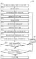
또 다른 예에서, 유체 처리 시스템 상으로 적재된 시약들을 식별하는 방법이 유체 처리 시스템의 제어기 안으로 시료를 준비하기 위한 프로토콜을 프로그래밍하는 단계, 유체 처리 시스템의 캐러셀 안으로 다수의 시약 베셀들을 적재하는 단계, 라벨 이미지들을 생성하기 위해 이미징 디바이스로 다수의 시약 베셀들의 개별 라벨들을 이미지화하는 단계, 라벨 이미지들에서의 정보를 제어기와 통신하는 데이터베이스에 위치된 식별 정보와 비교하는 단계, 및 프로토콜을 수행하기 위해 적절한 시약들이 캐러셀 안으로 적재되었는지를 결정하는 단계를 포함할 수 있다. 일부 실시예들에서, 다수의 시약 베셀들은 프로토콜에서 위치 정보에 따라 베셀 홀더 안으로 적재될 수 있다. 일부 실시예들에서, 프로토콜을 수행하기 위해 적절한 시약들이 베셀 홀더 안으로 적재되었는지를 결정하는 단계는 프로토콜에 따라 적절한 시약들이 로케이션들에서 베셀 홀더 안으로 적재되었는지를 결정하는 단계를 포함할 수 있다. 일부 실시예들에서, 프로토콜은 프로토콜에서 아웃라인된 단계 시퀀스에 기초하여 수행될 수 있다. 일부 실시예들에서, 다수의 시약 베셀들은 임의의 위치들에서 베셀 홀더 안으로 적재될 수 있다. 일부 실시예들에서, 프로토콜을 수행하기 위해 적절한 시약들이 베셀 홀더 안으로 적재되었는지를 결정하는 단계는 프로토콜을 수행하기 위해 충분한 시약들이 베셀 홀더 안으로 적재되었는지를 결정하는 단계를 포함할 수 있다. 일부 실시예들에서, 프로토콜은 베셀 홀더에서의 시약들의 로케이션들에 기초하여 결정된 단계 시퀀스에 기초하여 수행될 수 있다. 일부 실시예들에서, 라벨 이미지들을 생성하기 위해 이미징 디바이스로 다수의 시약 베셀들의 개별 라벨들을 이미지화하는 단계는 파노라마 이미지를 생성하기 위해 슬릿 스캔 프로세스로 개별 라벨들을 이미지화하는 단계를 포함할 수 있다. 라벨 이미지들을 생성하기 위해 이미징 디바이스로 다수의 시약 베셀들의 개별 라벨들을 이미지화하는 단계는 파노라마 이미지들을 획득하기 위해 개별 시약 베셀들을 회전시키는 단계를 추가로 포함할 수 있다. 그 방법은 기하학적 교정 라벨을 사용하여 개별 시약 베셀들의 회전 속력을 교정하는 단계를 추가로 포함할 수 있다. 일부 실시예들에서, 라벨 이미지들에서의 정보를 제어기와 통신하는 데이터베이스에 위치된 식별 정보와 비교하는 단계는 시각적 표시자 정보를 데이터베이스에서 저장된 제조자 정보와 비교하는 단계를 포함할 수 있다. 일부 실시예들에서, 그 방법은 프로토콜에서 시약들에 대해 특정된 목적지 로케이션을 결정하는 단계, 베셀 홀더에서의 시약 베셀로부터 액체의 체적을 흡입할 것을 피펫터에게 지시하는 단계, 및 식별된 시약에 대한 결정된 목적지 로케이션에서 흡입된 체적을 분배할 것을 피펫터에게 지시하는 단계를 추가로 포함할 수 있다. 일부 실시예들에서, 그 방법은 프로토콜을 수행하기 위해 베셀 홀더의 이미지들로부터 충분한 체적의 액체가 시약 베셀들 안으로 적재되었는지를 결정하는 단계와, 불충분한 액체가 시약 베셀에 남아 있으면 경보를 제공하는 단계를 추가로 포함할 수 있다. 일부 실시예들에서, 그 방법은 베셀 홀더의 이미지들로부터 캡들이 시약 베셀들로부터 제거되었는지를 결정하는 단계와, 캡이 시약 베셀로부터 제거되지 않았다면 경보를 제공하는 단계를 추가로 포함할 수 있다. 일부 실시예들에서, 그 방법은 베셀 홀더의 이미지들에 대한 이미지 품질을 결정하는 단계와, 베셀의 이미지들이 베셀 홀더의 이미지들에서 라벨들의 이미지들로부터 정보를 결정하기에 불충분하게 선명하면 경보를 제공하는 단계를 추가로 포함할 수 있다. 일부 실시예들에서, 그 방법은 수동 또는 시각적 확인 후 사용자가 시스템에 의해 생성된 경보들을 오버라이드하는 단계를 추가로 포함할 수 있다.In another example, a method of identifying reagents loaded onto a fluid handling system may include programming a protocol for preparing a sample into a controller of the fluid handling system, loading a plurality of reagent vessels into a carousel of the fluid handling system, imaging individual labels of the plurality of reagent vessels with an imaging device to generate label images, comparing information in the label images to identification information located in a database in communication with the controller, and determining that appropriate reagents have been loaded into the carousel for performing the protocol. In some embodiments, the plurality of reagent vessels may be loaded into vessel holders according to location information in the protocol. In some embodiments, determining that appropriate reagents have been loaded into the vessel holders for performing the protocol may include determining that appropriate reagents have been loaded into the vessel holders at locations according to the protocol. In some embodiments, the protocol may be performed based on a sequence of steps outlined in the protocol. In some embodiments, the plurality of reagent vessels may be loaded into the vessel holders at any locations. In some embodiments, the step of determining whether appropriate reagents are loaded into the vessel holder to perform the protocol may comprise the step of determining whether sufficient reagents are loaded into the vessel holder to perform the protocol. In some embodiments, the protocol may be performed based on a sequence of steps determined based on the locations of the reagents in the vessel holder. In some embodiments, the step of imaging the individual labels of the plurality of reagent vessels with the imaging device to generate label images may comprise the step of imaging the individual labels with a slit scan process to generate a panoramic image. The step of imaging the individual labels of the plurality of reagent vessels with the imaging device to generate label images may further comprise the step of rotating the individual reagent vessels to obtain the panoramic images. The method may further comprise the step of calibrating the rotational speed of the individual reagent vessels using a geometric correction label. In some embodiments, the step of comparing information in the label images to identification information located in a database in communication with the controller may comprise comparing the visual indicator information to manufacturer information stored in the database. In some embodiments, the method may further comprise determining a destination location specified for the reagents in the protocol, instructing a pipettor to aspirate a volume of liquid from a reagent vessel in the vessel holder, and instructing the pipettor to dispense the aspirated volume at the determined destination location for the identified reagent. In some embodiments, the method may further comprise determining whether a sufficient volume of liquid has been loaded into the reagent vessels from images of the vessel holder to perform the protocol, and providing an alert if insufficient liquid remains in the reagent vessels. In some embodiments, the method may further comprise determining whether caps have been removed from the reagent vessels from images of the vessel holder, and providing an alert if the caps have not been removed from the reagent vessels. In some embodiments, the method may further comprise determining image quality of the images of the vessel holder, and providing an alert if the images of the vessels are insufficiently clear to determine information from images of labels in the images of the vessel holder. In some embodiments, the method may further include a step of allowing the user to override alerts generated by the system after manual or visual confirmation.
도 1은 본 개시의 일 예에 따른 유체 처리 시스템의 블록도이다.
도 2는 하우징, 캐러셀 및 이미징 디바이스를 포함하는 도 2의 예시적인 유체 처리 시스템의 사시도이다.
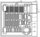
도 3은 캐러셀을 포함하는 다양한 컴포넌트들에 대한 공간들을 갖는 도 2의 하우징 안으로 적재하기 위한 데크의 평면도이다.
도 4a는 액체 바이알들과 같은 컴포넌트들을 수용하기 위한 복수의 리셉터클들을 갖는 캐러셀의 제1 예의 사시도이다.
도 4b는 캐러셀 드라이브 시스템을 도시하는 도 4a의 캐러셀의 사시도이다.
도 4c는 도 4b의 캐러셀 드라이브 시스템의 풀리(pulley) 어셈블리의 측면도이다.
도 4d는 도 4a의 캐러셀에 대한 받침대(pedestal) 드라이브 시스템의 측단면도이다.
도 5는 상이한 사이즈로 된 리셉터클들을 갖는 캐러셀의 제2 예의 사시도이다.
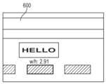
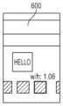
도 6은 도 1 및 도 2의 유체 처리 시스템에 대한 제어 패널의 스크린 샷이다.
도 7은 운반 디바이스 및 이미징 디바이스에 대해 상대적으로 위치되는 그리고 액체 바이알이 그 안에 위치되는 도 4a의 캐러셀의 리셉터클들의 하나의 클로즈업 사시도이다.
도 8은 캐러셀의 위치들 안으로 적재된 상이한 유형들의 인덱스들을 갖는 복수의 액체 바이알들의 사시도이다.
도 9a 내지 도 9c는 실린더형 액체 바이알 주위를 감싸는 직사각형 라벨의 상이한 부분들의 도면들이다.
도 10은 유체 처리 시스템 상으로 적재된 시약들을 식별하는 방법들을 예시하는 라인 도면이다.
도 11은 유체 처리 시스템을 동작시키는 방법들을 예시하는 라인 다이어그램이다.
도 12는 예시적인 등록 라벨을 도시하는 도면이다.
도 13a는 카메라 시료 속력보다 느린 받침대 회전 속력에서 취해진 도 12의 등록 라벨을 예시하는 도면이다.
도 13b는 카메라 시료 속력에 상응하는 받침대 회전 속력에서 취해진 도 12의 등록 라벨을 예시하는 도면이다.FIG. 1 is a block diagram of a fluid handling system according to an example of the present disclosure.
FIG. 2 is a perspective view of an exemplary fluid handling system of FIG. 2 including a housing, a carousel, and an imaging device.
FIG. 3 is a plan view of a deck for loading into the housing of FIG. 2 having spaces for various components including a carousel.
FIG. 4a is a perspective view of a first example of a carousel having a plurality of receptacles for accommodating components such as liquid vials.
FIG. 4b is a perspective view of the carousel of FIG. 4a illustrating a carousel drive system.
Figure 4c is a side view of the pulley assembly of the carousel drive system of Figure 4b.
FIG. 4d is a cross-sectional side view of the pedestal drive system for the carousel of FIG. 4a.
Figure 5 is a perspective view of a second example of a carousel having receptacles of different sizes.
Figure 6 is a screen shot of the control panel for the fluid handling system of Figures 1 and 2.
FIG. 7 is a close-up perspective view of one of the receptacles of the carousel of FIG. 4a positioned relative to the transport device and the imaging device and having a liquid vial positioned therein.
FIG. 8 is a perspective view of a plurality of liquid vials having different types of indices loaded into positions in a carousel.
Figures 9a to 9c are drawings of different portions of a rectangular label wrapping around a cylindrical liquid vial.
FIG. 10 is a line drawing illustrating methods for identifying reagents loaded onto a fluid handling system.
Figure 11 is a line diagram illustrating methods of operating a fluid handling system.
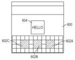
Figure 12 is a drawing illustrating an exemplary registration label.
Figure 13a is a drawing illustrating the registration label of Figure 12 taken at a pedestal rotation speed slower than the camera sample speed.
Figure 13b is a drawing illustrating the registration label of Figure 12 taken at a pedestal rotation speed corresponding to the camera sample speed.
도 1은 본 개시의 일 실시예에 따른 프로세싱 시스템(100)의 하이레벨 블록도이다. 프로세싱 시스템(100)은 구조체(140), 운반 디바이스(141), 프로세싱 장치(101) 및 이미징 디바이스(107)에 동작적으로 커플링되는 제어 컴퓨터(108)를 포함할 수 있다. 입출력 인터페이스들은 예시된 디바이스들과 외부 디바이스들 사이의 데이터 송신을 허용하는 이들 디바이스들의 각각에 존재할 수 있다. 프로세싱 시스템(100)은 본 개시에서 설명되는 바와 같은 유체 처리 시스템을 포함할 수 있다. 유체들은 시약들 등과 같은 다양한 액체들을 포함할 수 있다. 본 개시가 구현될 수 있는 예시적인 프로세싱 시스템은 캘리포니아 브레아의 Beckman Coulter, Inc.에 의해 판매되는 Biomek i7 자동화 워크스테이션이다.FIG. 1 is a high-level block diagram of a processing system (100) according to one embodiment of the present disclosure. The processing system (100) may include a control computer (108) operatively coupled to a structure (140), a transport device (141), a processing apparatus (101), and an imaging device (107). Input/output interfaces may be present on each of these devices to allow data transmission between the illustrated devices and external devices. The processing system (100) may include a fluid handling system as described in the present disclosure. The fluids may include various liquids, such as reagents, and the like. An exemplary processing system on which the present disclosure may be implemented is the Biomek i7 automated workstation sold by Beckman Coulter, Inc. of Brea, Calif.
예시 목적으로, 프로세싱 시스템(100)은 차세대 시퀀싱(next-generation sequencing)(NGS) 라이브러리들을 포함하는 핵산 조각들의 라이브러리들(예컨대, 세포 DNA 또는 RNA 분자들로부터 도출된 조각들의 라이브러리들)의 준비와 같이, 생물학적 시료들을 프로세싱하고 분석하기 위한 시스템으로서 주로 설명될 것이다. 예를 들어, 본 개시의 실시예들은, 무엇보다도, 바이알들에 도포된 라벨들의 내용을 평가하기 위해 캐러셀 안으로 적재된 바이알들을 식별하기 위하여 데크 상으로 적재되는 캐러셀 또는 트레이, 또는 일부 다른 시약 베셀 홀더를 이미지화하는 것을 포함할 수 있다. 그러나, 추가적인 예들에서, 프로세싱 시스템(100)은 컴포넌트들과 함께 또는 컴포넌트들에 대해 작업을 수행하는 머신 상으로 적재된 복수의 컴포넌트들을 식별하는 것을 수반할 수 있는 다른 프로세스들과 같이, 생물학적 시료들을 프로세싱하고 분석하는 것 외의 기능들을 수행하도록 구성될 수 있다.For illustrative purposes, the processing system (100) will be primarily described as a system for processing and analyzing biological samples, such as preparing libraries of nucleic acid fragments (e.g., libraries of fragments derived from cellular DNA or RNA molecules), including next-generation sequencing (NGS) libraries. For example, embodiments of the present disclosure may include imaging a carousel or tray, or some other reagent vessel holder, loaded onto a deck to identify vials loaded into the carousel to assess the contents of labels applied to the vials, among other things. However, in additional examples, the processing system (100) may be configured to perform functions other than processing and analyzing biological samples, such as other processes that may involve identifying a plurality of components loaded onto a machine that performs operations with or on the components.
구조체(140)는 하우징(예컨대, 도 2의 하우징(202)), 하우징을 지지하기 위한 다리들 또는 캐스터들, 전력원, 하우징 내에 적재 가능한 데크(105), 및 임의의 다른 적합한 특징부를 포함할 수 있다. 데크(105)는 컴포넌트들이 실험들, 분석들, 및 프로세스들을 위해 배치되고 액세스될 수 있는 평평한 물리적 표면과 같은 물리적 표면(예컨대, 도 2의 플랫폼(212))을 포함할 수 있다. 일부 사례들에서, 데크(105)는 바닥 또는 테이블탑 표면일 수 있다. 데크(105)는 상이한 컴포넌트들을 배치하기 위한 복수의 개별 데크 로케이션들(예컨대, 도 3의 로케이션들(L1~L28))로 세분될 수 있다. 그 로케이션들은 직 인접할 수 있거나 또는 서로 떨어져 있을 수 있다. 각각의 데크 로케이션은 디바이더들, 인서트들, 및/또는 상이한 데크 로케이션들을 분리하고 컴포넌트들을 포함하는 임의의 다른 지지 구조체를 포함할 수 있다. 예시적인 목적으로, 도 1은 데크(105) 상의 제1 로케이션(105A), 제2 로케이션(105B), 및 제3 로케이션(105C)을 도시하지만, 추가적인 로케이션들이 포함될 수 있다. 로케이션들(105A~105C) 중 하나 이상에는 액체의 바이알들과 같은 하나 이상의 컴포넌트들을 유지하기 위한 공간들을 포함할 수 있는 캐러셀(예컨대, 도 4a의 캐러셀(204))이 적재될 수 있다. 구조체(140)는, 무엇보다도, 이미징 디바이스(107)와의 상호작용을 용이하게 하기 위해 모터(예컨대, 도 4b의 모터(248B) 또는 도 7의 모터(308)) 또는 데크(105)에 대해 캐러셀을 회전시키기 위한 다른 디바이스를 추가로 포함할 수 있다. 더욱이, 구조체(140)의 모터, 또는 구조체(140)의 추가적인 모터가, 데크(105) 상으로 적재된 개별 바이알들, 데크(105) 상에 적재된 트레이 또는 데크(105) 상에 위치된 캐러셀을 회전시키는데 사용될 수 있다.The structure (140) may include a housing (e.g., housing (202) of FIG. 2), legs or casters for supporting the housing, a power source, a deck (105) loadable within the housing, and any other suitable features. The deck (105) may include a physical surface, such as a flat physical surface (e.g., platform (212) of FIG. 2), on which components may be placed and accessed for experiments, analyses, and processes. In some instances, the deck (105) may be a floor or tabletop surface. The deck (105) may be subdivided into a plurality of individual deck locations (e.g., locations L1-L28 of FIG. 3) for placing different components. The locations may be adjacent or spaced apart from one another. Each deck location may include dividers, inserts, and/or any other support structure that separates different deck locations and contains components. For illustrative purposes, FIG. 1 illustrates a first location (105A), a second location (105B), and a third location (105C) on the deck (105), although additional locations may be included. One or more of the locations (105A-105C) may be loaded with a carousel (e.g., carousel (204) of FIG. 4A) that may include spaces for holding one or more components, such as vials of liquid. The structure (140) may additionally include a motor (e.g., motor (248B) of FIG. 4B or motor (308) of FIG. 7) or other device for rotating the carousel relative to the deck (105), among other things, to facilitate interaction with the imaging device (107). Furthermore, the motor of the structure (140), or additional motors of the structure (140), may be used to rotate individual vials loaded onto the deck (105), trays loaded onto the deck (105), or a carousel positioned on the deck (105).
다수의 운반 디바이스들을 나타낼 수 있는 운반 디바이스(141)(예컨대, 도 7의 캐리지(304))는 데크(105)와 프로세싱 장치(101) 사이에서, 뿐만 아니라 데크(105) 상의 상이한 로케이션들 사이에서 컴포넌트들을 준비 및/또는 운반할 수 있다. 운반 디바이스들의 예들은 컨베이어들, 크레인들, 시료 트랙들, 픽 앤드 플레이스 그리퍼들(pick and place grippers), 독립적으로 이동시킬 수 있는 실험실 운반 엘리먼트들(예컨대, 퍽들, 허브들 또는 받침대들), 로봇 팔들, 및 다른 튜브 또는 컴포넌트 운반 메커니즘들을 포함할 수 있다. 일부 실시예들에서, 운반 디바이스(141)는 액체들을 운반하도록 구성되는 피펫팅 헤드를 포함한다. 이러한 피펫팅 헤드는 착탈식 피펫 팁들 내에서 액체들을 운반할 수 있고 마이크로웰 플레이트들과 같은 다른 실험실용품을 잡거나 또는 해제하는데 적합한 그리퍼들을 포함할 수 있다.A transport device (141), which may represent a plurality of transport devices (e.g., carriage (304) of FIG. 7), may prepare and/or transport components between the deck (105) and the processing device (101), as well as between different locations on the deck (105). Examples of transport devices may include conveyors, cranes, sample tracks, pick and place grippers, independently movable laboratory transport elements (e.g., pucks, hubs, or pedestals), robotic arms, and other tube or component transport mechanisms. In some embodiments, the transport device (141) includes a pipetting head configured to transport liquids. The pipetting head may include grippers adapted to transport liquids within removable pipette tips and to grasp or release other laboratory items, such as microwell plates.
프로세싱 장치(101)는 임의의 적합한 프로세스를 실행하기 위한 임의의 수의 머신들 또는 기구들을 포함할 수 있다. 예를 들어, 프로세싱 장치(101)는 분석기를 포함할 수 있으며, 그 분석기는 생물학적 시료와 같은 시료를 분석할 수 있는 임의의 적합한 기구를 포함할 수 있다. 분석기들의 예들은 분광광도계들, 광도계들, 질량 분광분석계들, 면역분석기들, 혈액학 분석기들, 미생물학 분석기들, 및/또는 분자 생물학 분석기들을 포함한다. 일부 실시예들에서, 프로세싱 장치(101)는 시료 스테이징 장치를 포함할 수 있다. 시료 스테이징 장치가 생물학적 시료들이 있는 시료 튜브들을 수용하기 위한 시료 제시 유닛, 시료 튜브들 또는 시료 보유 베셀들을 임시로 저장하기 위한 시료 저장 유닛, 분취기(aliquottor)와 같이 시료를 분취하기 위한 수단 또는 디바이스, 분석기에 필요한 시약들을 포함하는 적어도 하나의 시약 팩을 유지하기 위한 수단, 및 임의의 다른 적합한 특징부들을 포함할 수 있다.The processing device (101) may include any number of machines or instruments for performing any suitable process. For example, the processing device (101) may include an analyzer, which may include any suitable instrument capable of analyzing a sample, such as a biological sample. Examples of analyzers include spectrophotometers, photometers, mass spectrometers, immunoassay analyzers, hematology analyzers, microbiology analyzers, and/or molecular biology analyzers. In some embodiments, the processing device (101) may include a sample staging device. The sample staging device may include a sample presentation unit for receiving sample tubes containing biological samples, a sample storage unit for temporarily storing the sample tubes or sample holding vessels, a means or device for aliquoting a sample, such as an aliquottor, a means for holding at least one reagent pack containing reagents required for the analyzer, and any other suitable features.
하나 이상의 이미징 디바이스들(107)은 시스템(100) 안으로 적재된 임의의 단일 시약 바이알 라벨의 모든 부분들이 적어도 하나의 카메라의 뷰 내에 있는 것을 보장하기 위해 데크(105)에 관련하여 위치될 수 있다. 따라서, 시약 바이알의 둘레를 감싸는 시약 바이알 라벨의 경우, 하나 이상의 이미징 디바이스들(107)이, 거울들 또는 턴테이블들의 사용과 함께 또는 그러한 사용 없이, 각각의 시약 바이알의 완전한 360도 뷰를 가질 수 있다. 이미징 디바이스(107)는 데크(105)와 데크(105) 상의 임의의 컴포넌트들 또는 구조체(140)의 전체의 이미지를 캡처하기 위한 임의의 적합한 디바이스일 수 있다. 예를 들어, 이미징 디바이스(107)는 임의의 적합한 유형의 카메라, 이를테면 포토 카메라, 비디오 카메라, 3차원 이미지 카메라, 적외선 카메라 등일 수 있다. 일부 실시예들은 3차원 레이저 스캐너들, 적외선 광 깊이 감지 기술, 또는 물체들 및/또는 방의 3차원 표면 맵을 생성하기 위한 다른 도구들을 또한 포함할 수 있다. 예들에서, 이미징 디바이스(107)는, 이 기술분야에서 공지된 바와 같이, 파노라마 이미지들을 생성하기 위해 슬릿 스캔 기술을 이용할 수 있다. 이와 같이, 이미징 디바이스(107)는 이미징 디바이스(107)의 관람 영역을 제한하기 위해 하나 이상의 슬릿들을 갖는 적절한 슬라이드들 또는 덮개들을 포함할 수 있다. 더욱이, 가상 슬릿들이 디지털 사진과 조합하여 사용될 수 있다. 임의의 구성에서, 슬릿 스캔 이미징은 이미지의 전체 폭보다 작은 화소들의 열들을 획득하기 위해 슬릿 또는 가상 슬릿을 통해 개별적으로 회전되는 시약 바이알들의 이미지들을 고정 카메라로 촬상하는 것을 수반할 수 있다. 카메라의 시야에서의 물체들이, 이를테면 슬릿을 통해, 회전됨에 따라 정초점에 있거나 카메라의 뷰 내에 있는 화소들은 열들을 생성하는데 사용된다. 이미지들에서 물체들의 비초점 또는 비시야내(non-in-view) 부분들은 화소들의 열들로부터 트리밍될 수 있다. 그 물체들은 카메라의 시료 속력에 상응하는 일정한 회전 속력으로 회전할 수 있어서, 아래에서 더 상세히 논의되는 바와 같이, 다수의 이미지들이 생성될 수 있다. 물체들의 상이한 위치들에 대한 상이한 이미지들로부터의 화소들의 다수의 열들은 그러면 복수의 더 좁은 이미지들의 모음집인 펼쳐진 이미지를 형성하기 위해 함께 연결될 수 있다. 이런 식으로, 카메라는 유체 처리 시스템에 의해 시각적 표시자들의 인식을 위한 라벨, 예컨대, 텍스트 또는 심볼들을 준비하기 위해 시약 바이알의 라벨을 "박리"할 수 있다.One or more imaging devices (107) can be positioned relative to the deck (105) to ensure that all portions of any single reagent vial label loaded into the system (100) are within the view of at least one camera. Thus, for a reagent vial label that wraps around a reagent vial, the one or more imaging devices (107) can have a complete 360 degree view of each reagent vial, with or without the use of mirrors or turntables. The imaging device (107) can be any suitable device for capturing an image of the entire deck (105) and any components or structures (140) on the deck (105). For example, the imaging device (107) can be any suitable type of camera, such as a photo camera, a video camera, a 3D imaging camera, an infrared camera, etc. Some embodiments may also include 3D laser scanners, infrared optical depth sensing technology, or other tools for generating 3D surface maps of objects and/or rooms. In examples, the imaging device (107) may utilize slit scan technology, as is known in the art, to generate panoramic images. As such, the imaging device (107) may include suitable slides or covers having one or more slits to limit the viewing area of the imaging device (107). Furthermore, virtual slits may be used in combination with digital photography. In any configuration, slit scan imaging may involve capturing images of reagent vials that are individually rotated through a slit or virtual slit with a fixed camera to acquire columns of pixels that are smaller than the full width of the image. As objects in the camera's field of view are rotated, such as through the slit, the pixels that are in focus or within the camera's view are used to generate columns. Out-of-focus or non-in-view portions of objects in the images can be trimmed from the rows of pixels. The objects can be rotated at a constant rotational speed corresponding to the sample speed of the camera, so that multiple images can be generated, as discussed in more detail below. Multiple rows of pixels from different images for different positions of the objects can then be stitched together to form an unwrapped image, which is a collection of multiple narrower images. In this way, the camera can "peel" a label from a reagent vial to prepare the label, e.g., text or symbols, for recognition by a fluid handling system as visual indicators.
이미징 디바이스(107)는 구조체(140)에 또는 그 구조체 인근에 장착되는 복수의 이미징 디바이스들 중 하나의 이미징 디바이스를 포함할 수 있다. 추가적인 예에서, 다수의 이미징 디바이스들(107)은 데크(105) 상에 배치되는 시약 바이알들의 다수의 뷰들을 획득하도록 장착될 수 있다. 다수의 이미징 디바이스들은 시약 바이알들에 장착된 라벨들의 완전한 뷰들을 획득하기 위해 공간적으로 이격될 수 있다. 이미징 디바이스들(107)은 데크(105) 상의 로케이션의 삼백육십도에 관한 중첩 시야들을 갖도록 구조체(140)에 매우 가까이 장착될 수 있다. 예를 들어, 110도 시야를 갖는 네 개의 이미징 디바이스들(107)이 인접한 이미징 디바이스(107)로부터의 이미지들과는 각각의 단부에서 중첩하는 네 개의 이미지들을 생성하기 위해 균일하게 이격될 수 있다. 이와 같이, 이미지들은 복합 이미지를 형성하기 위해 함께 어셈블되거나 또는 "퀼팅(quilting)될" 수 있다. 더욱이, 추가적인 예에서, 거울들은 하나 이상의 이미징 디바이스들(107)이 단일 라벨의 완전한 시야를 획득하는 것을 용이하게 하기 위해 구조체(140)에 또는 그 구조체 인근에 위치될 수 있다.The imaging device (107) may include one of a plurality of imaging devices mounted on or near the structure (140). In a further example, multiple imaging devices (107) may be mounted to acquire multiple views of reagent vials positioned on the deck (105). The multiple imaging devices may be spatially spaced to acquire complete views of the labels mounted on the reagent vials. The imaging devices (107) may be mounted very close to the structure (140) so as to have overlapping fields of view about three hundred and sixty degrees of location on the deck (105). For example, four imaging devices (107) having 110 degree fields of view may be evenly spaced to produce four images that overlap at each end with the images from adjacent imaging devices (107). In this way, the images may be assembled or "quilted" together to form a composite image. Furthermore, in additional examples, mirrors may be positioned on or near the structure (140) to facilitate one or more imaging devices (107) obtaining a complete view of a single label.
제어 컴퓨터(108)는 프로세싱 시스템(100)에서 실행되는 프로세스들을 제어하며, 프로세스들을 초기에 구성하고 컴포넌트 셋업이 프로세스에 대해 올바르게 준비되었는지의 여부를 체크할 수 있다. 제어 컴퓨터(108)는 프로세싱 장치(101), 운반 디바이스(141), 및/또는 이미징 디바이스(107)에 메시지들을 제어 및/또는 송신할 수 있다. 제어 컴퓨터(108)는 데이터 프로세서(108A), 데이터 프로세서(108A)에 커플링된 비일시적 컴퓨터 판독가능 매체(108B) 및 데이터 저장소(108C), 하나 이상의 입력 디바이스들(108D) 및 하나 이상의 출력 디바이스들(108E)을 포함할 수 있다. 제어 컴퓨터(108)가 도 1에서 단일 엔티티로서 묘사되지만, 제어 컴퓨터(108)는 분산형 시스템에서 또는 클라우드 기반 환경에서 존재할 수 있다는 것이 이해된다. 추가적으로, 실시예들은 제어 컴퓨터(108), 프로세싱 장치(101), 운반 디바이스(141), 및/또는 이미징 디바이스(107)의 일부 또는 전부가 단일 디바이스에서 구성 부품들로서 조합되는 것을 허용한다.A control computer (108) controls the processes running on the processing system (100), may initially configure the processes, and may check whether component setup is properly prepared for the processes. The control computer (108) may control and/or send messages to the processing device (101), the transport device (141), and/or the imaging device (107). The control computer (108) may include a data processor (108A), a non-transitory computer-readable medium (108B) coupled to the data processor (108A), a data storage (108C), one or more input devices (108D), and one or more output devices (108E). Although the control computer (108) is depicted as a single entity in FIG. 1 , it is appreciated that the control computer (108) may reside in a distributed system or in a cloud-based environment. Additionally, embodiments allow for some or all of the control computer (108), processing device (101), transport device (141), and/or imaging device (107) to be combined as components in a single device.
출력 디바이스(108E)는 데이터를 출력할 수 있는 임의의 적합한 디바이스들을 포함할 수 있다. 출력 디바이스(108E)의 예들은 디스플레이 스크린들, 비디오 모니터들, 스피커들, 오디오 및 시각적 경보들 및 데이터 송신 디바이스들을 포함할 수 있다. 입력 디바이스(108D)는 데이터를 제어 컴퓨터(108)에 입력할 수 있는 임의의 적합한 디바이스를 포함할 수 있다. 입력 디바이스들의 예들은 버튼들, 키보드, 마우스, 터치스크린들, 터치 패드들, 마이크로폰들, 비디오 카메라들 및 센서들(예컨대, 광 센서, 위치 센서들, 속력 센서, 근접 센서들)을 포함할 수 있다.The output device (108E) may include any suitable device capable of outputting data. Examples of output devices (108E) may include display screens, video monitors, speakers, audio and visual alerts, and data transmission devices. The input device (108D) may include any suitable device capable of inputting data into the control computer (108). Examples of input devices may include buttons, a keyboard, a mouse, touchscreens, touch pads, microphones, video cameras, and sensors (e.g., light sensors, position sensors, speed sensors, proximity sensors).
데이터 프로세서(108A)는 임의의 적합한 데이터 컴퓨테이션 디바이스 또는 이러한 디바이스들의 조합을 포함할 수 있다. 예시적인 데이터 프로세서는 원하는 기능을 완수하기 위해 함께 작업하는 하나 이상의 마이크로프로세서들을 포함할 수 있다. 데이터 프로세서(108A)는 사용자 및/또는 시스템에 의해 생성된 요청들을 실행하기 위한 프로그램 컴포넌트들을 실행하기에 적절한 적어도 하나의 고속 데이터 프로세서를 포함하는 CPU를 포함할 수 있다. CPU는 AMD의 Athlon, Duron 및/또는 Opteron; IBM 및/또는 모토롤라의 PowerPC; IBM의 및 Sony의 셀 프로세서; 인텔의 Celeron, Itanium, Pentium, Xeon, 및/또는 XScale; 등의 프로세서(들)과 같은 마이크로프로세서일 수 있다.The data processor (108A) may include any suitable data computation device or combination of such devices. An exemplary data processor may include one or more microprocessors working together to accomplish the desired functionality. The data processor (108A) may include a CPU including at least one high-speed data processor suitable for executing program components for executing requests generated by a user and/or system. The CPU may be a microprocessor, such as an Athlon, Duron and/or Opteron from AMD; a PowerPC from IBM and/or Motorola; a Cell processor from IBM and Sony; a Celeron, Itanium, Pentium, Xeon, and/or XScale from Intel; or the like.
컴퓨터 판독가능 매체(108B)와 데이터 저장소(108C)는 전자 데이터를 저장할 수 있는 임의의 적합한 디바이스 또는 디바이스들일 수 있다. 메모리들의 예들은 하나 이상의 메모리 칩들, 디스크 드라이브들 등을 포함할 수 있다. 이러한 메모리들은 임의의 적합한 전기, 광학적, 및/또는 자기적 동작 모드를 사용하여 동작할 수 있다.The computer readable medium (108B) and data storage (108C) may be any suitable device or devices capable of storing electronic data. Examples of memories may include one or more memory chips, disk drives, etc. Such memories may operate using any suitable electrical, optical, and/or magnetic operating mode.
컴퓨터 판독가능 매체(108B)는 임의의 적합한 방법을 수행하기 위해 데이터 프로세서(108A)에 의해 실행 가능한 코드를 포함할 수 있다. 예를 들어, 컴퓨터 판독가능 매체(108B)는, 프로세싱 시스템(100)으로 하여금, 라벨 이미지들을 생성하기 위해 이미징 디바이스(107)로 캐러셀 상으로 적재된 다수의 시약 베셀들(예컨대, 바이알들)의 개별 라벨들을 이미지화하는 단계, 라벨 이미지들에서의 정보를 컴퓨터 판독가능 매체(108B)의 데이터베이스에 위치된 식별 정보와 비교하는 단계, 오퍼레이터에 의해 제어 컴퓨터(108) 안으로 프로그래밍된 프로토콜(108F)을 수행하기 위해 적절한 시약들이 캐러셀 안으로 적재되었는지를 결정하는 단계, 및 라벨 이미지들로부터의 정보와 프로그래밍된 프로토콜 사이의 임의의 차이들을 나타내는 경고 또는 경보를 오퍼레이터에게 출력하는 단계를 포함하는 자동화된 시약 식별 방법을 수행하게 하는 프로세서(108A)에 의해 실행 가능한 코드를 포함할 수 있다. 이러한 차이들은 프로세싱 시스템(100) 상에서 실행할 프로세스의 중단 또는 실패를 야기할 수 있거나 또는 프로세싱 시스템(100)에 의해 생성된 무효 또는 부정확한 정보를 초래할 수 있다.The computer-readable medium (108B) may include code executable by the data processor (108A) to perform any suitable method. For example, the computer-readable medium (108B) may include code executable by the processor (108A) to cause the processing system (100) to perform an automated reagent identification method including imaging individual labels of a plurality of reagent vessels (e.g., vials) loaded onto the carousel with the imaging device (107) to generate label images, comparing information in the label images to identification information located in a database of the computer-readable medium (108B), determining that appropriate reagents have been loaded into the carousel to perform a protocol (108F) programmed into the control computer (108) by an operator, and outputting an alert or warning to the operator indicating any differences between the information from the label images and the programmed protocol. These differences may cause interruption or failure of a process to be executed on the processing system (100) or may result in invalid or incorrect information being generated by the processing system (100).
컴퓨터 판독가능 매체(108B)는 하나 이상의 프로토콜들(예컨대, 생물학적 시료를 프로세싱하기 위한 프로토콜 또는 라이브러리 구축 프로세스를 위한 프로토콜)을 위한 프로세스 단계들을 수신하고 저장하도록, 뿐만 아니라 하나 이상의 프로토콜들을 위한 프로세스 단계들을 실행하기 위해 이미징 디바이스(107), 구조체(140), 운반 디바이스(141), 및/또는 프로세싱 장치(101)를 제어하도록 데이터 프로세서(108A)에 의해 실행 가능한 코드를 포함할 수 있다. 컴퓨터 판독가능 매체(108B)는 프로세싱 장치(101)로부터의 결과들(예컨대, 생물학적 시료를 분석한 결과들)을 수신하고 추가적인 분석(예컨대, 환자를 진단)을 위해 그 결과들을 포워딩하거나 또는 그 결과들을 사용하기 위한, 데이터 프로세서(108A)에 의해 실행 가능한 코드를 또한 포함할 수 있다. 추가적으로, 컴퓨터 판독가능 매체(108B)는 데크(105)의 이미지를 획득하며, 데크(105)의 이미지들에서 정보를 식별하며, 데이터 저장소(108C) 또는 컴퓨터 판독가능 매체(108B)에 저장된 정보를 사용하여 이미지들에서의 정보를 암호해독하며, 암호해독된 정보를 프로토콜(108F)에 포함된 정보와 비교하고, 차이들을 출력 디바이스(108E)에서 사용자에게 디스플레이하기 위한, 데이터 프로세서(108A)에 의해 실행 가능한 코드를 포함할 수 있다.The computer-readable medium (108B) may include code executable by the data processor (108A) to receive and store process steps for one or more protocols (e.g., a protocol for processing a biological sample or a protocol for building a library), as well as to control the imaging device (107), the structure (140), the transport device (141), and/or the processing device (101) to execute the process steps for the one or more protocols. The computer-readable medium (108B) may also include code executable by the data processor (108A) to receive results from the processing device (101) (e.g., results from analyzing a biological sample) and forward or use the results for further analysis (e.g., diagnosing a patient). Additionally, the computer-readable medium (108B) may include code executable by the data processor (108A) to obtain images of the deck (105), identify information in the images of the deck (105), decrypt the information in the images using information stored in the data storage (108C) or the computer-readable medium (108B), compare the decrypted information with information contained in the protocol (108F), and display the differences to the user on an output device (108E).
데이터 저장소 컴포넌트(108C)는 제어 컴퓨터(108) 내부 또는 외부에 있을 수 있다. 데이터 저장소 컴포넌트(108C)는 하나 이상의 메모리 칩들, 디스크 드라이브들 등을 포함하는 하나 이상의 메모리들을 포함할 수 있다. 데이터 저장소 컴포넌트(108C)는 Oracle™ 또는 Sybase™로부터 상업적으로 입수 가능한 것들과 같은 기존의, 고장 허용(fault tolerant), 관계형, 확장가능, 보안 데이터베이스를 또한 포함할 수 있다. 일부 실시예들에서, 데이터 저장소(108C)는 프로토콜들(108F)과 이미지들(108G)을 저장할 수 있다. 데이터 저장소 컴포넌트(108C)는 프로토콜들을 포함하는, 데이터 프로세서(108A)에 대한 명령어들을 추가적으로 포함할 수 있다. 컴퓨터 판독가능 매체(108B)와 데이터 저장소 컴포넌트(108C)는 임의의 적합한 저장 디바이스, 이를테면 비휘발성 메모리, 자기 메모리, 플래시 메모리, 휘발성 메모리, 프로그램가능 판독전용 메모리 등을 포함할 수 있다.The data storage component (108C) may be internal or external to the control computer (108). The data storage component (108C) may include one or more memories, including one or more memory chips, disk drives, etc. The data storage component (108C) may also include a conventional, fault tolerant, relational, scalable, secure database, such as those commercially available from Oracle™ or Sybase™. In some embodiments, the data storage component (108C) may store protocols (108F) and images (108G). The data storage component (108C) may additionally include instructions for the data processor (108A), including the protocols. The computer-readable medium (108B) and the data storage component (108C) may include any suitable storage device, such as non-volatile memory, magnetic memory, flash memory, volatile memory, programmable read-only memory, etc.
데이터 저장소 컴포넌트(108C)에서의 프로토콜들(108F)은 하나 이상의 프로토콜들에 관한 정보를 포함할 수 있다. 프로토콜이 완료할 하나 이상의 프로세싱 단계들에 관한 정보, 프로세스 동안 사용되는 컴포넌트들, 컴포넌트 로케이션 레이아웃, 및/또는 프로세스를 완료하기 위한 임의의 다른 적합한 정보를 포함할 수 있다. 예를 들어, 프로토콜이 생물학적 시료를 프로세싱 또는 DNA 라이브러리를 프로세싱하기 위한 하나 이상의 순서화된 단계들을 포함할 수 있다. 프로토콜이 프로세스를 시작하기 전에 컴포넌트들의 리스트를 준비하기 위한 단계들을 또한 포함할 수 있다. 컴포넌트들은, 운반 디바이스(141)가 컴포넌트들을 프로세싱 장치(101)에 운반하기 위하여 그들 컴포넌트들을 획득할 수 있는, 데크(105) 상의 또는 캐러셀(예컨대, 도 4a의 캐러셀(204))에서의 특정 로케이션들에 매핑될 수 있다. 이 매핑은 미리 결정된 목적지에 체적을 분배하기 위해 캐러셀에서의 시약 베셀로부터의 액체의 체적을 흡입할 것을 피펫터에게 지시하는 명령어들과 같은 운반 디바이스(141)를 동작시키기 위한 명령어들로서 인코딩될 수 있고, 매핑은 또한 사용자가 데크(105) 및 캐러셀 상에 컴포넌트들을 배치할 수 있도록 사용자에게 보여진 가상 이미지에 의해 표현될 수 있다. 실시예들은 프로세싱 시스템(100)이 다수의 프로세스들(예컨대, 다수의 상이한 시료 프로세스들 또는 준비 절차들)을 위해 사용되는 것을 허용한다. 따라서, 다수의 프로토콜들(108F)에 관한 정보는 필요할 때 저장되고 취출될 수 있다. 데크(105) 및 캐러셀 상의 컴포넌트들은 제1 프로세스에서 제2 프로세스로 변경될 때, 또는 제1 프로세스를 재시작할 때 필요한 대로 재배열, 변경, 및/또는 보충될 수 있다.Protocols (108F) in the data storage component (108C) may include information regarding one or more protocols. The protocol may include information regarding one or more processing steps to be completed, components used during the process, component location layout, and/or any other suitable information for completing the process. For example, the protocol may include one or more ordered steps for processing a biological sample or processing a DNA library. The protocol may also include steps for preparing a list of components prior to initiating the process. The components may be mapped to specific locations on the deck (105) or in a carousel (e.g., carousel (204) of FIG. 4A ) from which the transport device (141) may obtain the components for transporting them to the processing apparatus (101). This mapping may be encoded as instructions to operate the transport device (141), such as instructions to instruct the pipettor to aspirate a volume of liquid from a reagent vessel in the carousel to dispense the volume to a predetermined destination, and the mapping may also be represented by a virtual image shown to the user so that the user can position components on the deck (105) and the carousel. Embodiments allow the processing system (100) to be used for multiple processes (e.g., multiple different sample processes or preparation procedures). Accordingly, information regarding multiple protocols (108F) may be stored and retrieved when needed. Components on the deck (105) and the carousel may be rearranged, changed, and/or supplemented as needed when changing from a first process to a second process, or when restarting a first process.
이미지가 하나 이상의 물체들의 묘사를 포함할 수 있다. 예들로서, 이미지들은 디지털 픽처들 또는 사진들, 비디오들, 3차원 픽처들 및 비디오들, 컬러 포토들, 흑백 포토들, HDR(high dynamic range) 이미지들(예컨대, 동일한 피사체의 상이한 노출들로 촬상된 다수의 이미지들을 조합하는 것) 등을 포함할 수 있다. 예들에서, 이미지들(108G)은 슬릿이 형성되는 이동 가능한 또는 가상 슬라이드가 이미징 디바이스(107)와 데크(105) 사이에 위치되는 슬릿 스캔 이미지들을 추가적으로 포함할 수 있다. 이미지들(108G)은 퀼팅된 또는 펼쳐진 이미지들을 포함할 수 있다.The images may include depictions of one or more objects. For example, the images may include digital pictures or photographs, videos, three-dimensional pictures and videos, color photos, black and white photos, high dynamic range (HDR) images (e.g., combining multiple images of the same subject taken at different exposures), etc. In examples, the images (108G) may additionally include slit scan images in which a movable or virtual slide in which a slit is formed is positioned between the imaging device (107) and the deck (105). The images (108G) may include quilted or unfolded images.
데이터 저장소(108C)에서의 이미지들(108G)은 데크(105) 및 캐러셀, 뿐만 아니라 데크(105) 및 캐러셀 상의 또는 그 안에 배치된 컴포넌트들과 그들 컴포넌트들 상에 배치된 라벨들의 실세계 시각적 표현을 포함할 수 있다. 각각의 이미지에서, 데크(105)와 캐러셀은 운반 디바이스(141)에 액세스 가능한 로케이션들에 배치된 프로토콜을 실행하기 위한 컴포넌트들로 특정한 프로세스를 시작하기 위한 준비 상태로 도시될 수 있다. 이미지들(108G)의 각각은 저장된 프로토콜들(108F)로부터 특정 프로토콜에 연관될 수 있다. 일부 실시예들에서, 특정한 프로토콜에 대한 단일 이미지가 있을 수 있다. 다른 실시예들에서, 특정한 프로토콜에 대한 다수의 이미지들(예컨대, 상이한 각도들로부터, 상이한 조명 레벨들로, 또는 일부 로케이션들에서의 허용 가능한 실험실용품 대체물들을 포함함)이 있을 수 있다. 이미지들(108G)은 JPEG, TIFF, GIF, BMP, PNG, 및/또는 원시(RAW) 이미지 파일들, 뿐만 아니라 AVI, WMV, MOV, MP4, 및/또는 FLV 비디오 파일들을 포함하는 다양한 유형들 또는 포맷들의 이미지 파일들로서 저장될 수 있다.Images (108G) in the data store (108C) may include real-world visual representations of the deck (105) and the carousel, as well as components positioned on or within the deck (105) and the carousel, and labels positioned on those components. In each image, the deck (105) and the carousel may be depicted as being ready to initiate a particular process with components for executing a protocol positioned at locations accessible to the transport device (141). Each of the images (108G) may be associated with a particular protocol from the stored protocols (108F). In some embodiments, there may be a single image for a particular protocol. In other embodiments, there may be multiple images for a particular protocol (e.g., from different angles, with different lighting levels, or including acceptable labware alternatives at certain locations). The images (108G) may be stored as image files of various types or formats, including JPEG, TIFF, GIF, BMP, PNG, and/or RAW image files, as well as AVI, WMV, MOV, MP4, and/or FLV video files.
데크(105)는 상이한 컴포넌트들을 스테이징하기 위한 복수의 개별 데크 로케이션들로 세분될 수 있다. 개별 로케이션들은 임의의 적합한 사이즈로 될 수 있다. 복수의 로케이션들을 갖는 데크(105)의 일 예가 도 3에 도시된다. 도 3의 데크(220)는 별개의 유형들의 컴포넌트들 또는 컴포넌트들의 패키지들을 위한 별개의 로케이션으로서 작동할 수 있는 열 순환기(thermal cycler)(224), 뿐만 아니라 L1 내지 L28로 번호 매겨진 개별 영역들을 도시한다. 데크(105)는 원하는 대로 추가적인 로케이션들 또는 더 적은 로케이션들을 가질 수 있다. 이들 로케이션들이 번호 매겨지거나 또는 명명될 수 있지만, 그것들은 시스템의 물리적 실시예들에서 데크(105) 상에 물리적으로 라벨링 또는 마킹될 수 있거나 또는 되지 않을 수 있다.The deck (105) may be subdivided into a plurality of individual deck locations for staging different components. The individual locations may be of any suitable size. An example of a deck (105) having a plurality of locations is illustrated in FIG. 3 . The deck (220) of FIG. 3 illustrates a thermal cycler (224) that may operate as separate locations for separate types of components or packages of components, as well as individual regions numbered L1 through L28. The deck (105) may have additional or fewer locations as desired. While these locations may be numbered or named, they may or may not be physically labeled or marked on the deck (105) in physical embodiments of the system.
본 개시에서 논의된 바와 같이, 이미지들, 이를테면 이미지들(108G)은, 오퍼레이터에 의해 프로세싱 시스템(100) 안으로 프로그래밍된 프로토콜(108F)을 완료하기 위해 적절한 컴포넌트들이 데크(105) 및 캐러셀 안으로 적재되는지와, 프로토콜에 의해 요구되면, 그들 컴포넌트들이 프로그래밍된 프로토콜을 실행하기 위한 올바른 위치들에 위치되는지를 검증하는데 사용될 수 있다.As discussed in this disclosure, images, such as images (108G), can be used to verify that the appropriate components are loaded into the deck (105) and carousel to complete a protocol (108F) programmed into the processing system (100) by an operator, and, if required by the protocol, that those components are positioned in the correct locations to execute the programmed protocol.
도 2는 도 2의 프로세싱 시스템(100)의 일 예를 포함할 수 있는 유체 처리 시스템(200)의 사시도이다. 유체 처리 시스템(200)은 하우징(202), 캐러셀(204) 및 이미징 디바이스(206)를 포함할 수 있다. 하우징(202)은 캐러셀(204)이 위치될 수 있는 인클로저를 형성하는 복수의 벽들 또는 패널들을 포함할 수 있다. 인클로저는 인클로저 내에 캐러셀(204)을 캡슐화하도록 덮개 패널(210)이 위치될 수 있는 개구부(208)를 가질 수 있다. 하우징(202)은 데크(105)(도 1) 또는 데크(220)(도 3)와 같은 데크가 위치될 수 있는 플랫폼(212)을 추가적으로 포함할 수 있다. 데크는 캐러셀(204)을 수용하기 위한 슬롯 또는 소켓을 포함할 수 있다. 예들에서, 슬롯 또는 소켓은 이미징 디바이스(206)에 관련하여 미리 결정된 또는 공지 위치에 캐러셀(204)을 유지하도록 구성될 수 있다. 플랫폼(212)은 이미징 디바이스(206)에 관련하여 미리 결정된 또는 공지된 위치에 데크를 유지할 수 있다. 하우징(202)은 제어 컴퓨터(108)(도 1)의 것들과 같은 제어기(214)를 유지하기 위한 공간을 추가적으로 포함할 수 있다. 제어기(214)는 네트워크(216)와는, 이를테면 무선 또는 유선 통신 링크를 통해 통신하도록 구성될 수 있다.FIG. 2 is a perspective view of a fluid handling system (200) that may include an example of the processing system (100) of FIG. 2. The fluid handling system (200) may include a housing (202), a carousel (204), and an imaging device (206). The housing (202) may include a plurality of walls or panels forming an enclosure in which the carousel (204) may be positioned. The enclosure may have an opening (208) in which a cover panel (210) may be positioned to encapsulate the carousel (204) within the enclosure. The housing (202) may additionally include a platform (212) on which a deck, such as deck (105) ( FIG. 1 ) or deck (220) ( FIG. 3 ), may be positioned. The deck may include a slot or socket for receiving the carousel (204). In examples, the slot or socket may be configured to hold the carousel (204) in a predetermined or known location relative to the imaging device (206). The platform (212) may hold the deck in a predetermined or known location relative to the imaging device (206). The housing (202) may additionally include space for holding a controller (214), such as those of the control computer (108) (FIG. 1). The controller (214) may be configured to communicate with the network (216), such as via a wireless or wired communications link.
도 1의 이미징 디바이스(107)를 포함할 수 있는 이미징 디바이스(206)는 고정 로케이션에서 하우징(202) 내에 위치될 수 있다. 이미징 디바이스(206)는 캐러셀(204)의 단일 로케이션을 가리키도록 구성될 수 있다. 동시에, 프로세싱 장치(101) 또는 운반 디바이스(141)의 피펫터(도 1)가 캐러셀(204)의 로케이션에 액세스하기 위해 하우징(202) 내에 위치될 수 있다. 캐러셀(204)은 피펫터 및 이미징 디바이스(206)에 대해 상이한 로케이션들을 제시하기 위해 돌거나 또는 회전할 수 있다. 다른 예들에서, 이미징 디바이스(206)는 하우징(202)의 내부의 상이한 부분들에 걸쳐 관람 영역을 이동시키도록 하우징(202) 내에 장착될 수 있다.An imaging device (206), which may include the imaging device (107) of FIG. 1, may be positioned within the housing (202) in a fixed location. The imaging device (206) may be configured to point to a single location in the carousel (204). At the same time, a pipettor (FIG. 1) of the processing device (101) or the transport device (141) may be positioned within the housing (202) to access the location of the carousel (204). The carousel (204) may be rotated or pivoted to present different locations to the pipettor and the imaging device (206). In other examples, the imaging device (206) may be mounted within the housing (202) to move the viewing area across different portions of the interior of the housing (202).
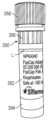
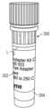
제어기(214)는 캐러셀(204) 안으로 적재된 그리고 하우징(202) 내의 데크 상으로 적재된 컴포넌트들을 위한 프로토콜을 실행하도록 구성될 수 있다. 제어기(214)가 프로토콜 별로 캐러셀(204) 안으로 적재된 바이알 세트에 대해 하나 이상의 단계 시퀀스들을 수행하기 위해, 제어기(214)는 캐러셀(204) 내의 각각의 바이알의 로케이션, 예컨대, 캐러셀(204) 내의 각각의 로케이션에서 각각의 바이알의 내용물들을 알아야 한다. 본 개시에서 논의된 바와 같이, 제어기(214)는 캐러셀(204)의 이미지들과 캐러셀(204) 안으로 적재된 컴포넌트들을 획득하기 위해 이미징 디바이스(206)를 동작시키도록 구성될 수 있다. 특히, 캐러셀(204)에는 재료의 바이알들이 적재될 수 있으며, 각각의 바이알은 각각의 바이알의 내용물들, 각각의 바이알이 속하는 바이알 세트, 바이알 세트의 제조업자, 프로세싱 시스템(200)이 바이알 세트로 실행하기 위한 하나 이상의 프로토콜들 등에 관한 식별 정보를 제공하는 라벨을 가질 수 있다. 바이알 라벨들의 이미지들은 라벨들에서 제시된 정보를 인식하기 위해 제어기(214)에 의해 판독될 수 있다. 라벨들로부터 판독된 정보는 도 1의 매체(108B)와 같은 컴퓨터 판독가능 매체에 저장된, 네트워크(216)로부터 획득된 정보와 같은 정보와 비교될 수 있다. 컴퓨터 판독가능 매체에 저장되는 정보는 운반 디바이스(141)가 각각의 바이알과 상호작용할 수 있는 순서와 같이, 바이알 세트와 상호작용하기 위한 하나 이상의 단계 시퀀스들을 포함하는 바이알 세트에 대한 프로토콜을 포함할 수 있다. 따라서, 제어기(214)는 프로토콜이 실행되기 전에 라벨들로부터 판독된 정보로부터 식별되는 바와 같은 하우징(202) 안으로 적재된 실제 내용물들과 프로토콜을 비교할 수 있고, 필요하다면, 유체 처리 시스템(200)이 프로토콜을 개시하기 전에 임의의 오류들 또는 잠재적 오류들을 오퍼레이터에게 알릴 수 있다.The controller (214) can be configured to execute a protocol for components loaded into the carousel (204) and loaded onto a deck within the housing (202). In order for the controller (214) to perform one or more sequences of steps for a set of vials loaded into the carousel (204) per the protocol, the controller (214) must know the location of each vial within the carousel (204), e.g., the contents of each vial at each location within the carousel (204). As discussed herein, the controller (214) can be configured to operate the imaging device (206) to acquire images of the carousel (204) and the components loaded into the carousel (204). In particular, the carousel (204) can be loaded with vials of material, each vial having a label that provides identifying information regarding the contents of each vial, the vial set to which each vial belongs, the manufacturer of the vial set, one or more protocols for the processing system (200) to execute with the vial set, etc. Images of the vial labels can be read by the controller (214) to recognize the information presented in the labels. The information read from the labels can be compared to information obtained from the network (216), such as information stored on a computer-readable medium, such as the medium (108B) of FIG. 1. The information stored on the computer-readable medium can include a protocol for the vial set, including one or more sequences of steps for interacting with the vial set, such as the order in which the transport device (141) can interact with each vial. Accordingly, the controller (214) can compare the protocol with the actual contents loaded into the housing (202), as identified from information read from the labels, before the protocol is executed, and, if necessary, can notify the operator of any errors or potential errors before the fluid handling system (200) initiates the protocol.
도 3은 도 2의 하우징(202)의 플랫폼(212) 안으로 적재하기 위한 데크(220)의 평면도이다. 데크(220)는 캐러셀(204)을 포함하는 다양한 컴포넌트들에 대한 공간들 또는 로케이션들을 포함할 수 있다. 이미징 디바이스(206)는 이미징 디바이스가 플랫폼(212)의 전체를 덮는 시야(222)를 생성할 수 있도록 플랫폼(212)에 관련하여 하우징(202) 내에 장착될 수 있다. 그러나, 다양한 예들에서, 시야(222)는 플랫폼(212)의 부분들만을 덮도록 구성될 수 있고 시야(222)를 플랫폼(212)을 가로질러 상이한 로케이션들까지 이동시켜 총 커버리지를 성취할 수 있는 다수의 이미징 디바이스가 사용될 수 있거나 또는 관절형 이미징 디바이스가 사용될 수 있다.FIG. 3 is a plan view of a deck (220) for loading into a platform (212) of a housing (202) of FIG. 2. The deck (220) may include spaces or locations for various components including the carousel (204). An imaging device (206) may be mounted within the housing (202) relative to the platform (212) such that the imaging device can generate a field of view (222) that covers the entire platform (212). However, in various examples, the field of view (222) may be configured to cover only portions of the platform (212), and multiple imaging devices may be used or an articulated imaging device may be used that can move the field of view (222) across the platform (212) to different locations to achieve total coverage.
도 3은 별개의 유형들의 컴포넌트들 또는 컴포넌트들의 패키지들을 위한 별개의 로케이션으로서 작동할 수 있는 L1~ L28로 번호 매겨진 로케이션들, 뿐만 아니라 열 순환기(224)와 같은 다른 컴포넌트들을 포함하는 데크(220)를 도시한다. 데크(220)의 예들은, 원하는 대로, 추가적인 로케이션들 또는 더 적은 로케이션들을 가질 수 있다. 이들 로케이션들이 번호 매겨지거나 또는 명명될 수 있지만, 로케이션들은 유체 처리 시스템(200)의 물리적 실시예들에서 데크(220) 상에 물리적으로 라벨링 또는 마킹될 수 있거나 또는 되지 않을 수 있다. 유체 처리 시스템(200)의 예들에서, 로케이션들의 일부 또는 전부는 특정한 프로토콜에 따라 미리 정의된 유형의 컴포넌트에 의해 점유될 수 있다. 예를 들어, 로케이션들(L1~ L27)에는 패키지 또는 시약 키트의 컴포넌트 또는 프로토콜에 의해 특정된 바와 같은 컴포넌트가 적재될 수 있고, 로케이션(L28)에는 캐러셀(204)이 적재될 수 있다. 로케이션들(L1~L27)의 일부는 동일한 유형의 컴포넌트를 포함할 수 있다. 컴포넌트들은 테스트 튜브들, 마이크로웰 또는 마이크로타이터 플레이트들, 피펫 팁들, 플레이트 뚜껑들, 저장용기들 또는 임의의 다른 적합한 실험실용품 컴포넌트를 포함할 수 있다. 컴포넌트들은 실험실 장비 항목, 이를테면 셰이커(shaker), 교반기, 믹서, 온도 배양기, 진공 매니폴드, 자기 플레이트, 열순환기 등을 또한 포함할 수 있다. 예들에서, 하나 이상의 로케이션들은 물리적으로 구조체(140)(도 1), 하우징(202)(도 2) 또는 데크(220)(도 3)의 일부일 수 있거나, 또는 플랫폼(212) 상에 배치된 별개의 컴포넌트일 수 있다. 로케이션들(L1~L28)의 각각은 운반 디바이스(141)(도 1)에 의해 액세스될 수 있다. 예를 들어, 로케이션들(L1~L28)과, 열 순환기(224)는 구조체(140) 또는 데크(220)와는 물리적으로 별개일 수 있다.FIG. 3 illustrates a deck (220) including locations numbered L1 through L28 that can act as separate locations for separate types of components or packages of components, as well as other components, such as a thermal cycler (224). Examples of the deck (220) may have additional or fewer locations, as desired. While these locations may be numbered or named, the locations may or may not be physically labeled or marked on the deck (220) in physical embodiments of the fluid handling system (200). In examples of the fluid handling system (200), some or all of the locations may be occupied by predefined types of components according to a particular protocol. For example, locations (L1-L27) may be loaded with components as specified by a component or protocol of a package or reagent kit, and location (L28) may be loaded with a carousel (204). Some of the locations (L1-L27) may include components of the same type. The components may include test tubes, microwells or microtiter plates, pipette tips, plate lids, reservoirs, or any other suitable laboratory equipment components. The components may also include laboratory equipment items, such as a shaker, agitator, a mixer, a temperature incubator, a vacuum manifold, a magnetic plate, a thermocycler, etc. In examples, one or more of the locations may be physically part of the structure (140) ( FIG. 1 ), the housing (202) ( FIG. 2 ), or the deck (220) ( FIG. 3 ), or may be separate components disposed on the platform (212). Each of the locations (L1-L28) can be accessed by a transport device (141) (Fig. 1). For example, the locations (L1-L28) and the thermal cycler (224) can be physically separate from the structure (140) or the deck (220).
이미징 디바이스(206)는 로케이션들(L1~L27)의 각각에서의 하나 이상의 컴포넌트의 존재와 로케이션(L28)에서의 캐러셀(204)의 존재를 인식하도록 구성될 수 있다. 더욱이, 이미징 디바이스(206)는 로케이션들(L1 - L27)의 각각에 위치된 하나 이상의 컴포넌트들과 로케이션(L28)의 캐러셀(204)로부터 정보를 판독하도록 구성될 수 있다. 도 3에서 알 수 있는 바와 같이, 캐러셀(204)은 캐러셀(204) 자체 내에 복수의 로케이션들을 포함할 수 있다. 그들 로케이션들의 각각은 컴포넌트들, 예컨대, 액체의 바이알들이 캐러셀(204) 안으로, 예컨대, 프로토콜에 따라 원하는 방식으로 적재될 수 있도록 캐러셀(204) 상에 번호 매겨질 수 있다. 이미징 디바이스(206)에 의해 촬상된 캐러셀(206)의 이미지들은 캐러셀(204) 안으로 적재된 바이알들의 라벨들로부터 정보를 판독하는데 사용될 수 있다.The imaging device (206) may be configured to recognize the presence of one or more components at each of the locations (L1-L27) and the presence of the carousel (204) at the location (L28). Furthermore, the imaging device (206) may be configured to read information from the one or more components located at each of the locations (L1-L27) and the carousel (204) at the location (L28). As can be seen in FIG. 3, the carousel (204) may include a plurality of locations within the carousel (204) itself. Each of those locations may be numbered on the carousel (204) such that components, e.g., vials of liquid, may be loaded into the carousel (204) in a desired manner, e.g., according to a protocol. Images of the carousel (206) captured by the imaging device (206) can be used to read information from the labels of vials loaded into the carousel (204).
도 4a는 도 3으로부터의 캐러셀(204)의 제1 예의 사시도이다. 캐러셀(204)은 리셉터클들(230), 베이스(232), 연장부(234), 손잡이(236) 및 포켓들(238)을 포함할 수 있다.FIG. 4A is a perspective view of a first example of a carousel (204) from FIG. 3. The carousel (204) may include receptacles (230), a base (232), an extension (234), a handle (236), and pockets (238).
베이스(232)는 복수의 바이알들을 공통 구조체 안으로 링킹하기 위한 플랫폼을 포함할 수 있다. 베이스(232)는 중심축(A)에 대한 회전을 용이하게 하기 위한 형상으로 둥글거나 또는 원형일 수 있다. 중심축(A)은 베이스(232)의 원형 모양의 중심으로부터 연장될 수 있다. 연장부(234)는 축(A)을 따라 연장하여 리셉터클들(230A~230P)과 그 안에 위치된 바이알들 위에 손잡이(236)를 위한 간극을 제공할 수 있다. 손잡이(236)는 사용자에 의해 캐러셀(204)의 잡고 들어올리고 운반하는데 용이하게 하기 위해 인체공학적으로 성형된 몸체를 포함할 수 있다. 언급된 바와 같이, 캐러셀(204)은 축(A)을 중심으로 회전하도록 구성될 수 있다. 예를 들어, 유체 처리 시스템(200)의 모터 또는 드라이브 메커니즘이 회전 움직임을 부여하기 위해 캐러셀(204)과 맞물리도록 구성될 수 있다. 드라이브 메커니즘은 손잡이(236) 또는 베이스(232)와 맞물리도록 구성될 수 있다.The base (232) may include a platform for linking a plurality of vials into a common structure. The base (232) may be round or circular in shape to facilitate rotation about a central axis (A). The central axis (A) may extend from the center of the circular shape of the base (232). An extension (234) may extend along the axis (A) to provide clearance for a handle (236) over the receptacles (230A-230P) and the vials positioned therein. The handle (236) may include an ergonomically shaped body to facilitate grasping, lifting, and carrying of the carousel (204) by a user. As noted, the carousel (204) may be configured to rotate about the axis (A). For example, a motor or drive mechanism of the fluid handling system (200) may be configured to engage the carousel (204) to impart rotational motion. The drive mechanism may be configured to engage with the handle (236) or the base (232).
캐러셀(204)은 액체 바이알(240)과 같이, 컴포넌트들을 수용하기 위한 복수의 리셉터클들(230)을 포함할 수 있다. 도 4a의 예에서, 캐러셀(204)은 열여섯 개의 리셉터클들(230A~230P)을 포함한다. 리셉터클들(230A~230P)은 이를테면 숫자 인덱스들(242)을 사용하여, 캐러셀 상에 물리적으로 라벨링될 수 있다. 숫자 인덱스들(242)은 대응하여 번호 매겨진 액체 바이알 리스트를 갖는 프로토콜에 따라 복수의 액체 바이알들(240)을 캐러셀(204) 안으로 적재하기 위해 유체 처리 시스템(200)의 오퍼레이터에 의해 사용될 수 있다. 언급된 바와 같이, 캐러셀(204)은 리셉터클들(230A~230P)을 이미징 디바이스(206) 및 운반 디바이스(141)와 정렬하기 위해 회전하도록 구성될 수 있다. 그러나, 다른 예들에서, 캐러셀(204)은 제어기(214)가 리셉터클들(230)의 로케이션들을 알도록 데크(220) 안으로 하나의 배향에서만 적재되도록 구성될 수 있다. 제어기(214)는 숫자 인덱스들(242)을 판독하여 캐러셀(204)의 배향을 결정하기 위해 이미징 디바이스(206)를 사용하도록 구성될 수 있다.The carousel (204) may include a plurality of receptacles (230) for receiving components, such as liquid vials (240). In the example of FIG. 4A, the carousel (204) includes sixteen receptacles (230A-230P). The receptacles (230A-230P) may be physically labeled on the carousel, such as using numeric indices (242). The numeric indices (242) may be used by an operator of the fluid handling system (200) to load a plurality of liquid vials (240) into the carousel (204) according to a protocol having a correspondingly numbered list of liquid vials. As mentioned, the carousel (204) may be configured to rotate to align the receptacles (230A-230P) with the imaging device (206) and the transport device (141). However, in other examples, the carousel (204) may be configured to be loaded into the deck (220) in only one orientation so that the controller (214) knows the locations of the receptacles (230). The controller (214) may be configured to use the imaging device (206) to determine the orientation of the carousel (204) by reading the numeric indices (242).
리셉터클들(230A~230P)은 받침대들(244A~244P) 및 슬리브들(246A~246P)을 각각 포함할 수 있다. 받침대들(244A~244P)은 바이알들이 안착되는 로케이션들을 포함할 수 있다. 받침대들(244A~244P)의 로케이션들은 리셉터클들(230A~230P)에 위치된 바이알들을 찾을 위치를 운반 디바이스(141)가 알 수 있도록 알려진 위치들에서 베이스(232) 상에 위치될 수 있다. 슬리브들(246A~246P)은 받침대들(244A~244P)로부터 각각 연장되어, 그 안에 위치되는 바이알들에 대한 지지를 제공할 수 있다. 슬리브들(246A~246P)은 시약 바이알들을 곧게 선 자세로 유지하기에 충분한 길이의 기다란 튜브를 포함할 수 있다. 슬리브들(246A~246P)은, 예를 들어, 청소를 용이하게 하기 위해 받침대들(244A~244P)로부터 분리 가능할 수 있다. 슬리브들(246A~246P)은 그 안의 바이알들의 관람을 용이하게 하기 위해 투명 재료로 이루어질 수 있다. 특히, 슬리브들(246A~246P)은 이미징 디바이스(206)가 슬리브들(246A~246P) 내부의 바이알들의 라벨들을 보는 것을 허용하기 위해 투명하거나 또는 맑을 수 있다. 포켓들(238A~238P)은 리셉터클들(230A~230P)의 각각에 제공될 수 있다. 포켓들(238A~238P)은 리셉터클들(230A~230P) 중 각각의 리셉터클에 위치된 바이알에 대해, 바이알(240)을 위한 캡(248)과 같은 캡을 수용하고 유지하도록 구성될 수 있다. 이와 같이, 포켓들(238A~238P)의 각각은 캡의 움직임을 방지 또는 억제하기 위해 베이스(232) 안으로 연장하여 내려오는 오목부 또는 공동을 포함할 수 있다. 예들에서, 포켓들(238A~238P)은 축(A)에 관련하여 캡들의 원주 또는 방사형 움직임을 방지하는 직사각형 오목부들을 포함한다. 더욱이, 포켓들(238A~238P)에는 캡들을 고정하기 위한 플랜지들 또는 다른 특징부들이 제공될 수 있다.The receptacles (230A-230P) may each include pedestals (244A-244P) and sleeves (246A-246P). The pedestals (244A-244P) may include locations at which vials are to be seated. The locations of the pedestals (244A-244P) may be positioned on the base (232) at known locations so that the transport device (141) knows where to find the vials positioned in the receptacles (230A-230P). The sleeves (246A-246P) may each extend from the pedestals (244A-244P) to provide support for the vials positioned therein. The sleeves (246A-246P) may include an elongated tube of sufficient length to maintain the reagent vials in an upright position. The sleeves (246A-246P) may be removable from the bases (244A-244P), for example, to facilitate cleaning. The sleeves (246A-246P) may be made of a transparent material to facilitate viewing of the vials therein. In particular, the sleeves (246A-246P) may be transparent or clear to allow the imaging device (206) to view the labels of the vials within the sleeves (246A-246P). Pockets (238A-238P) may be provided in each of the receptacles (230A-230P). The pockets (238A-238P) may be configured to receive and retain a cap, such as a cap (248) for a vial (240), for a vial positioned in each of the receptacles (230A-230P). As such, each of the pockets (238A-238P) may include a recess or cavity extending down into the base (232) to prevent or inhibit movement of the cap. In examples, the pockets (238A-238P) include rectangular recesses that prevent circumferential or radial movement of the caps relative to the axis (A). Furthermore, the pockets (238A-238P) may be provided with flanges or other features for securing the caps.
캐러셀(204)은 도 4b 및 도 4c에 도시된 바와 같이, 원심력을 생성하기 위해 축(A)을 중심으로 회전하거나 또는 돌도록 구성될 수 있다. 추가적으로, 캐러셀(204)의 회전은 바이알들을 운반 디바이스(141) 및/또는 이미징 디바이스(107)(도 1)와 정렬하는데 사용될 수 있다. 예를 들어, 캐러셀(204)은 드라이브 허브(247A), 베어링(247B), 와셔(247C) 및 풀리(247D)을 포함할 수 있다. 벨트(248A)는 모터(248B) 및 풀리(247D)에 연결되어 캐러셀(204)에 회전 입력을 제공할 수 있다. 모터(248B)는 스테퍼 모터를 포함할 수 있다. 드라이브 허브(247A)는 복수의 상이한 회전 위치들 중 하나의 회전 위치에서, 캐러셀(204)이 끼워맞춤될 수 있는 스플라인 또는 사슬톱니바퀴(sprocket)를 포함할 수 있다. 캐러셀(204)의 회전을 선택적으로 억제하기 위해 (예컨대, 구조체(140)의 지지 브래킷에서의 컷아웃을 통해) 캐러셀(204)과 맞물리는 작동가능 탭(248D)이 솔레노이드(248C)에 제공될 수 있고 솔레노이드는 그러한 작동가능 탭을 포함할 수 있다. 더욱이, 리셉터클들(230A~230P)의 각각은, 도 4d에 도시된 바와 같이, 캐러셀(204)의 원주 배향에 상관없이, 이미징 디바이스(204)가 리셉터클들(230A~230P)의 각각에 위치된 바이알들의 360도 뷰를 허용하도록 개별적으로 회전하도록 구성될 수 있다. 다시 말하면, 받침대들(244A~244P)의 각각, 뿐만 아니라 자신에 장착된 슬리브들(246A~246P)은 그것에 안착된 시약 바이알이 동시에 회전할 수 있도록 중심축(B)을 중심으로 회전하도록 구성될 수 있다. 따라서, 받침대들(244A~244P)의 각각은 베이스(232)에 대해 회전할 수 있는 베이스(232)에 장착된 턴테이블을 포함함으로써, 추가적으로 슬리브들(246A~246P)을 회전시킬 수 있다. 도 4d에 도시된 바와 같이, 받침대(244A)는 슬리브(246A), O링 그루브(249A), O링(249B), 베어링(249C) 및 드라이브(249D)를 포함할 수 있다. 받침대(244A)는 시약 입력 드라이브(249E)와의 맞물림에 의해 회전될 수 있으며, 이 시약 입력 드라이브는 드라이브 허브(247A) 상에 동심적으로 장착될 수 있다. 드라이브 허브(247A)가 회전함에 따라, O링(249B)이 끼워맞춤되는 드라이브 허브(247A)의 외부 직경은 받침대(244A)와 맞물려 베어링(249C)에서 받침대(244A)의 회전을 야기한다. 받침대들(244A~244P)의 각각은 동시에 회전되도록 드라이브 허브(249E)의 외부 직경 주위에서 위치될 수 있다. 도 7 및 도 8을 참조하여 더 상세히 논의되는 바와 같이, 이미징 디바이스(206)는 바이알들(240) 상의 라벨들의 파노라마 이미지들을 생성하기 위해, 슬릿 스캔 기술, 또는 다른 기술을 사용하도록 구성될 수 있다.The carousel (204) may be configured to rotate or pivot about an axis (A) to generate centrifugal force, as illustrated in FIGS. 4B and 4C. Additionally, the rotation of the carousel (204) may be used to align the vials with the transport device (141) and/or the imaging device (107) (FIG. 1). For example, the carousel (204) may include a drive hub (247A), a bearing (247B), a washer (247C), and a pulley (247D). A belt (248A) may be connected to the motor (248B) and the pulley (247D) to provide rotational input to the carousel (204). The motor (248B) may include a stepper motor. The drive hub (247A) may include splines or sprockets on which the carousel (204) may be engaged at one of a plurality of different rotational positions. An actuable tab (248D) may be provided on the solenoid (248C) to engage the carousel (204) (e.g., via a cutout in the support bracket of the structure (140)) to selectively inhibit rotation of the carousel (204), and the solenoid may include such an actuable tab. Furthermore, each of the receptacles (230A-230P) may be individually configured to rotate so that the imaging device (204) allows a 360 degree view of the vials positioned in each of the receptacles (230A-230P), regardless of the circumferential orientation of the carousel (204), as illustrated in FIG. 4D . In other words, each of the pedestals (244A to 244P), as well as the sleeves (246A to 246P) mounted thereon, can be configured to rotate about the central axis (B) so that the reagent vials mounted thereon can rotate simultaneously. Accordingly, each of the pedestals (244A to 244P) can additionally rotate the sleeves (246A to 246P) by including a turntable mounted on the base (232) that can rotate relative to the base (232). As illustrated in FIG. 4D, the pedestal (244A) can include a sleeve (246A), an O-ring groove (249A), an O-ring (249B), a bearing (249C), and a drive (249D). The pedestal (244A) can be rotated by engagement with a reagent input drive (249E), which can be concentrically mounted on the drive hub (247A). As the drive hub (247A) rotates, the outer diameter of the drive hub (247A), into which the O-ring (249B) is fitted, engages the pedestal (244A), causing rotation of the pedestal (244A) on the bearing (249C). Each of the pedestals (244A-244P) can be positioned around the outer diameter of the drive hub (249E) so as to rotate simultaneously. As discussed in more detail with reference to FIGS. 7 and 8, the imaging device (206) can be configured to use slit scan technology, or other technology, to generate panoramic images of the labels on the vials (240).
도 5는 상이한 사이즈로 된 리셉터클들을 갖는 도 3의 캐러셀(204)의 대안적 예의 사시도이다. 캐러셀(250)은 리셉터클들(252), 베이스(254), 연장부(256), 손잡이(258), 포켓들(260) 및 숫자 인덱스들(262)을 포함할 수 있다. 캐러셀(250)은, 이를테면 축(A)을 중심으로 회전하도록 구성될 수 있는 것에 의해, 캐러셀(204)과는 유사한 방식으로 기능을 할 수 있다. 캐러셀(250)은 데크(220)의 동일한 표면 영역을 점유하기 위해서 캐러셀(204)과는 동일한 풋프린트를 가질 수 있다. 예를 들어, 베이스(254)는 베이스(232)와는 동일한 형상 및 사이즈, 예컨대, 원과 직경을 가질 수 있다. 그러나, 캐러셀(250)은 상이한 사이즈 및 형상으로 된 더 적은 리셉터클들을 특징으로 한다.FIG. 5 is a perspective view of an alternative example of the carousel (204) of FIG. 3 having receptacles of different sizes. The carousel (250) can include receptacles (252), a base (254), an extension (256), a handle (258), pockets (260), and numeric indices (262). The carousel (250) can function in a similar manner as the carousel (204), such as by being configured to rotate about an axis (A). The carousel (250) can have the same footprint as the carousel (204) so as to occupy the same surface area of the deck (220). For example, the base (254) can have the same shape and size as the base (232), such as a circle and diameter. However, the carousel (250) features fewer receptacles of different sizes and shapes.
리셉터클들(252A~252E)은 받침대들(264A~264E) 및 슬리브들(266A~266E)을 각각 포함할 수 있다. 리셉터클들(252A~252D)은 리셉터클들(230A~230P)보다 큰 직경들이 있는 실린더형 리셉터클들을 포함할 수 있다. 리셉터클(252E)은 정사각형 형상 용기를 포함할 수 있다. 리셉터클(252E)은, 예를 들어, 리셉터클들(252A~252D)의 시약들과 함께 사용될 수 있는 바이알에, 예컨대, 80% 에탄올, 물, 비드들, 기타 등등과 같은 벌크 재료를 수용하기 위해 리셉터클들(252A~252D)보다 클 수 있다. 슬리브들(266A~266E)은 리셉터클들(252A~252E)내에 위치될 때 바이알(268)과 같은 바이알들의 관람을 허용하기 위해 맑거나 또는 투명할 수 있다. 포켓들(260A~260E)은 바이알(268)을 위한 캡(270)과 같은 캡을 수용하도록 구성될 수 있다.The receptacles (252A-252E) may include holders (264A-264E) and sleeves (266A-266E), respectively. The receptacles (252A-252D) may include cylindrical receptacles having larger diameters than the receptacles (230A-230P). The receptacle (252E) may include a square shaped container. The receptacle (252E) may be larger than the receptacles (252A-252D) to accommodate bulk materials, such as, for example, 80% ethanol, water, beads, and the like, in vials that may be used with the reagents of the receptacles (252A-252D). The sleeves (266A-266E) may be clear or transparent to allow viewing of the vials, such as vials (268), when positioned within the receptacles (252A-252E). The pockets (260A-260E) may be configured to receive a cap, such as a cap (270) for a vial (268).
도 6은 도 1 및 도 2의 유체 처리 시스템(200)에 대한 제어 패널(282)의 스크린 샷(280)의 개략도이다. 제어 패널(282)은 제어 컴퓨터(108)(도 1)를 위한 입력 및 출력 디바이스를 포함할 수 있거나 또는 제어기(214)를 위한 인터페이스의 일 실시예를 포함할 수 있다. 스크린 샷(280)은 타이틀 블록(284), 시약들 블록(286), 체적 블록(288) 및 캐러셀 로케이션 블록(290), 뿐만 아니라 저장 온도 블록 및 준비 온도 블록과 같은 다른 정보 블록들을 포함하여, 프로토콜에 대한 정보를 포함할 수 있다. 시약들 블록(286)은 제어 컴퓨터(108) 안으로 프로그래밍된 프로토콜에 의해 사용될 시약 리스팅을 포함할 수 있다. 이와 같이, 시스템(200)의 오퍼레이터가 캐러셀 로케이션 블록(290)에서의 각각의 캐러셀 로케이션에 대한 특정 시약을 제어 패널(282) 안으로 입력할 수 있다. 캐러셀 로케이션 블록(290)은 캐러셀들(204 및 250)과 같은 주어진 캐러셀에 대한 숫자 인덱스들에 대응하는 숫자 인덱스들(242 및 262)과 같은 숫자 인덱스들을 포함할 수 있다.FIG. 6 is a schematic diagram of a screen shot (280) of a control panel (282) for the fluid handling system (200) of FIGS. 1 and 2. The control panel (282) may include input and output devices for the control computer (108) (FIG. 1) or may include an embodiment of an interface for the controller (214). The screen shot (280) may include information about the protocol, including a title block (284), a reagents block (286), a volume block (288), and a carousel location block (290), as well as other information blocks, such as a storage temperature block and a preparation temperature block. The reagents block (286) may include a listing of reagents to be used by the protocol programmed into the control computer (108). In this manner, an operator of the system (200) can enter specific reagents for each carousel location in the carousel location block (290) into the control panel (282). The carousel location block (290) can include numeric indices, such as numeric indices (242 and 262), that correspond to numeric indices for a given carousel, such as carousels (204 and 250).
제어 패널(282)을 사용하여, 랩 기술자가 하우징(202)으로부터 원격으로 배치(batch)를 구성할 수 있다. 배치의 구성은 프로토콜, 시료들, 인덱스들, 방법 옵션들, 및 안전한 중지 포인트들의 선택을 포함할 수 있다. 랩 기술자는 인근의 프린터에서 RWA(reagent work aid)를 인쇄할 수 있다. RWA는 구성되었던 배치를 완료하는데 필요한 시약들에 관한 정보를 제공할 수 있다. RWA는 시약 저장 조건, 시약 박스 이름, 시약 이름, 해동 명령어들(적용 가능하면), 소용돌이(vortexing) 명령들(적용 가능하면), 및 원심분리 명령들(적용 가능하면)을 포함할 수 있다. RWA 상의 항목들의 순서는 사전 프로세싱(해동, 소용돌이, 원심분리)을 능률화하는 측면에서 응용 과학자에 의해 가장 타당성 있게 결정될 수 있다. 랩 기술자는 시약들을 RWA에 따라 취출할 수 있고 임의의 요구된 또는 원하는 사전 프로세싱 단계들을 수행할 수 있다. 이와 같이, 랩 기술자는 시약 키트를 획득하며, 그것의 내용물들을 평가하며, 시스템(100)이 이와 같이 구성되면, 응용 과학자에 의해 개발된 프로토콜에 따라 시약 바이알들의 리스팅을 제어 패널(282) 안으로 입력하고, 시약 바이알들을 캐러셀 안으로 적재함으로써 시료 프로세싱 절차를 시작할 수 있다. 다른 예들에서, 시약 바이알들의 리스팅은 랩 기술자가 시약 바이알들의 리스팅을 수동으로 입력할 필요가 없도록 시스템(100) 안으로 이미 프로그래밍된 프로토콜에 포함될 수 있다.Using the control panel (282), a lab technician can remotely configure a batch from the housing (202). Configuring a batch can include selection of protocol, samples, indices, method options, and safe stopping points. The lab technician can print a reagent work aid (RWA) from a nearby printer. The RWA can provide information regarding the reagents needed to complete the configured batch. The RWA can include reagent storage conditions, reagent box name, reagent name, thawing instructions (if applicable), vortexing instructions (if applicable), and centrifugation instructions (if applicable). The order of items on the RWA can be determined by the application scientist to be most feasible in terms of streamlining preprocessing (thawing, vortexing, centrifugation). The lab technician can withdraw reagents according to the RWA and perform any required or desired preprocessing steps. In this manner, the lab technician obtains the reagent kit, evaluates its contents, and once the system (100) is configured, the lab technician can begin the sample processing procedure by entering a listing of reagent vials into the control panel (282) according to a protocol developed by the application scientist and loading the reagent vials into the carousel. In other examples, the listing of reagent vials may be included in a protocol already programmed into the system (100) so that the lab technician does not have to manually enter the listing of reagent vials.
도 7은 액체 바이알(240G)이 안에 위치되는 도 4a의 리셉터클(230G)의 클로즈업 사시도이다. 리셉터클(230G)은 캐러셀(204) 안으로 적재된 복수의 리셉터클들 중 하나를 포함할 수 있다. 캐러셀(204)은 도 1의 유체 처리 시스템(200)의 하우징(202) 안으로 적재될 수 있다. 캐러셀(204)은 운반 디바이스(141) 및 이미징 디바이스(206)에 관련하여 배치될 수 있다. 운반 디바이스(141)는 플랫폼(212)을 가로지르는 레일들(300A 및 300B)과 플랫폼(212)의 폭의 길이에 걸쳐 있을 수 있고 레일들(300A 및 300B) 상에서 미끄러지도록 구성될 수 있는 브릿지(302)를 갖는 오버헤드 크레인 시스템을 포함할 수 있다. 캐리지(304)는 브릿지(302)에 커플링될 수 있고 플랫폼(212)의 폭을 가로질러 브릿지(302)를 따라 이동하도록 구성될 수 있다. 브릿지(302)와 캐리지(304)는 프로토콜에 따라 이동하도록 적절한 모터들 및 전력원들, 뿐만 아니라 제어 패널(214)에 동작적으로 커플링될 수 있다. 캐리지(304)는 프로토콜을 수행하기 위한 하나 이상의 기구들에 커플링될 수 있다. 예시된 예에서, 캐리지(304)는 피펫터(306)에 커플링된다. 피펫터(306)는 축(B)과는 정렬하는 위치로 이동될 때 액체 바이알(240G) 안으로 축방향으로 이동하도록 구성될 수 있다.FIG. 7 is a close-up perspective view of the receptacle (230G) of FIG. 4A having a liquid vial (240G) positioned therein. The receptacle (230G) may comprise one of a plurality of receptacles loaded into a carousel (204). The carousel (204) may be loaded into the housing (202) of the fluid handling system (200) of FIG. 1. The carousel (204) may be positioned relative to the transport device (141) and the imaging device (206). The transport device (141) may comprise an overhead crane system having rails (300A and 300B) that extend across the platform (212) and a bridge (302) that may span the length of the width of the platform (212) and may be configured to slide on the rails (300A and 300B). The carriage (304) may be coupled to the bridge (302) and configured to move along the bridge (302) across the width of the platform (212). The bridge (302) and carriage (304) may be operatively coupled to suitable motors and power sources, as well as a control panel (214) to move them in accordance with the protocol. The carriage (304) may be coupled to one or more mechanisms for performing the protocol. In the illustrated example, the carriage (304) is coupled to a pipettor (306). The pipettor (306) may be configured to move axially into a liquid vial (240G) when moved into a position aligned with the axis (B).
일단 사전 프로세싱이 완료되면, 랩 기술자는 시약 바이알들을 뚜껑을 벗기며, 바이알들을 캐러셀(204)의 리셉터클들(230) 안으로 적재하고, 캐러셀(204) 상의 바이알들에 인접한 캡들을 포켓들(238)에 놓을 수 있다. 예를 들어, 캡(248G)은 바이알(240G)로부터 제거되고 포켓(238G)에 배치될 수 있다. 캡들 중 어느 것이라도 자신들의 각각의 튜브에 테더링되면, 랩 기술자는 튜브로부터 분리되는 것을 허용하도록 테더를 절단하여 피펫터(306)와의 잠재적인 충돌들을 피할 수 있다. 슬리브(246G)는 바이알(240G)의 길이를 따라 바이알(240G)에 대한 라벨을 가로질러, 깔쭈기(knurling)(249G)까지 연장될 수 있다. 슬리브(246G)는 교차 오염을 피하기 위해 캡(248G)이 커플링되도록 구성되는 나사산 아래에서 바이알(240G)을 잡는 것을 허용하기 위해 깔쭈기(249G)의 바로 앞에서 멈출 수 있다. 그러나, 슬리브(246G)는 축(B)을 따라, 또는 실질적으로 그 축을 따라 곧게 선 자세로 액체 바이알(240G)을 유지하기에 충분한 길이로 된다.Once preprocessing is complete, the lab technician can uncap the reagent vials, load the vials into the receptacles (230) of the carousel (204), and place caps adjacent to the vials on the carousel (204) into the pockets (238). For example, a cap (248G) can be removed from a vial (240G) and placed in a pocket (238G). If any of the caps are tethered to their respective tubes, the lab technician can cut the tether to allow them to detach from the tubes to avoid potential collisions with the pipettor (306). The sleeve (246G) can extend along the length of the vial (240G) and across the label for the vial (240G) to a knurling (249G). The sleeve (246G) may stop just in front of the funnel (249G) to allow the vial (240G) to be held under the threads to which the cap (248G) is configured to couple to avoid cross contamination. However, the sleeve (246G) is of sufficient length to maintain the liquid vial (240G) in a straight position along the axis (B), or substantially along that axis.
언급된 바와 같이, 받침대(244G)는 바이알(240G)이 안착될 수 있는 받침대를 포함할 수 있고 받침대(244G)는 모터(308) 또는 다른 모터(예컨대, 도 4b의 모터(248B))로부터의 전력 하에 회전하도록 구성될 수 있다. 받침대(244G)는 추가적으로 슬리브(246G)를 수용하기 위한 플랜지(312G)를 포함할 수 있다. 받침대(244G)는 베이스(232)의 웰(314G) 내에 놓일 수 있다. 웰(314G)은 받침대(244G)가 이를테면 샤프트 또는 자기 커플링을 통해 모터(308)와 인터페이싱하도록 위치될 수 있는 베이스(232) 내의 로케이션일 수 있다. 예들에서, 모터(308)는 턴테이블 시스템의 부분을 포함할 수 있다. 웰(314G)은 받침대(244G)보다 클 수 있다. 받침대(244G)는 베이스(232)에 해제 가능하게 부착되도록 구성될 수 있다. 이와 같이, 캐러셀(204)은 상이한 사이즈들의 프로토콜의 컴포넌트들 또는 바이알들을 수용하기 위해 상이한 사이즈들의 받침대들을 수용하도록 구성될 수 있다. 예를 들어, 상이한 사이즈로 된 받침대들은 상이한 사이즈로 된 슬리브들 또는 튜브들을 수용하기 위해 상이한 사이즈로 된 플랜지들을 가질 수 있다. 슬리브 사이즈는, 예를 들어, 피펫팅을 용이하게 하기 위해 축(B)을 따라 곧게 선 자세로 바이알을 배향하기 위하여 바이알 사이즈에 밀접하게 일치할 수 있다. 받침대들은 받침대가 확고히 부착되었다는 촉각 피드백을 오퍼레이터에게 제공하기 위해, 제자리에 이를테면 스냅 특징부를 통해 유지되도록 구성될 수 있다. 상이한 사이즈로 된 받침대들은, 이를테면 컬러 코딩 또는 일부 다른 시스템 식별 시스템으로 분류될 수 있다. 유체 처리 시스템(200)은 제어 컴퓨터(108)에서 오퍼레이터에 의해 입력될 수 있는 것과 같이, 컴퓨터 판독가능 매체(108B)에 저장된 프로토콜을 교차 참조하기 위해 각각의 받침대 상의, 또는 캐러셀(204) 상의 코딩을 판독하도록 구성될 수 있다.As mentioned, the pedestal (244G) may include a pedestal upon which the vial (240G) may be seated and the pedestal (244G) may be configured to rotate under power from the motor (308) or another motor (e.g., motor (248B) of FIG. 4B). The pedestal (244G) may additionally include a flange (312G) for receiving a sleeve (246G). The pedestal (244G) may be disposed within a well (314G) of the base (232). The well (314G) may be a location within the base (232) where the pedestal (244G) may be positioned to interface with the motor (308), such as via a shaft or magnetic coupling. In examples, the motor (308) may comprise part of a turntable system. The well (314G) may be larger than the pedestal (244G). The pedestals (244G) may be configured to be releasably attached to the base (232). As such, the carousel (204) may be configured to accommodate pedestals of different sizes to accommodate components or vials of different sizes of protocols. For example, the pedestals of different sizes may have flanges of different sizes to accommodate sleeves or tubes of different sizes. The sleeve size may closely match the vial size to, for example, orient the vial in an upright position along the axis (B) to facilitate pipetting. The pedestals may be configured to remain in place, such as via a snap feature, to provide tactile feedback to the operator that the pedestals are securely attached. The pedestals of different sizes may be identified, such as by color coding or some other system identification system. The fluid handling system (200) may be configured to read coding on each pedestal, or on the carousel (204), to cross-reference protocols stored on a computer readable medium (108B), such as may be entered by an operator into the control computer (108).
랩 기술자는 제어 패널(214) 또는 제어 패널(282) 상의 사전 구성되는 배치의 실행을 개시한 다음, 캐러셀(204)을 하우징(202) 상으로 적재할 수 있다. 랩 기술자는 하우징(202)의 덮개 패널(210)을 닫을 수 있다. 추가적으로, 캐러셀(204)에는 덮개 또는 뚜껑이 제공될 수 있다. 덮개는 베이스(232)와 맞물리고 리셉터클들(230)을 둘러싸는 실린더형 벽과 베이스(232)에 대향하고 리셉터클들(230)을 캡슐화하는 상단 패널을 포함할 수 있다. 덮개는 환경 오염물들로부터 리셉터클들(230) 안으로 적재된 시약들을 보호할 수 있고, 특히 캐러셀(204)이 연장부(234)와 손잡이(236)를 갖지 않도록 구성되면, 캐러셀(204)의 운반을 도울 수 있다. 상단 패널은 피펫터(306)와 같은 기구에 의한 액세스를 허용하기 위해 그리고 이미징 디바이스(206)가 덮개 하에 위치된 시약 바이알들을 보는 것을 허용하기 위해 개구부들 또는 액세스 포인트들, 이를테면 슬롯들을 포함할 수 있다. 덮개는 캐러셀(204)이 회전할 수 있는 동안 정지상태로 유지되도록 구성될 수 있다. 다른 예들에서, 덮개는 캐러셀(204)과 함께 회전하도록 구성될 수 있다.The lab technician can initiate execution of a pre-configured batch on the control panel (214) or the control panel (282) and then load the carousel (204) onto the housing (202). The lab technician can close the cover panel (210) of the housing (202). Additionally, the carousel (204) can be provided with a cover or lid. The cover can include a cylindrical wall that engages the base (232) and surrounds the receptacles (230) and a top panel that faces the base (232) and encapsulates the receptacles (230). The cover can protect reagents loaded into the receptacles (230) from environmental contaminants and can aid in transporting the carousel (204), particularly if the carousel (204) is configured without an extension (234) and a handle (236). The top panel may include openings or access points, such as slots, to allow access by an instrument, such as a pipettor (306), and to allow the imaging device (206) to view reagent vials positioned beneath the cover. The cover may be configured to remain stationary while the carousel (204) may rotate. In other examples, the cover may be configured to rotate with the carousel (204).
일단 캐러셀(204)을 위한 덮개가 닫히면, 시스템(200)은 이미징 디바이스(206)를 사용하여 리셉터클들(230)의 회전과 연계하여 슬릿 스캔 사진을 수행할 수 있다. 예를 들어, 리셉터클(230G)은 받침대(244G)와 슬리브(246G)를 포함할 수 있다. 받침대(244G)는 바이알(240G)의 "펼쳐진" 이미지를 획득하기 위해, 모터(308), 또는 일부 다른 스피닝 메커니즘에 커플될 수 있다. 받침대(244G)는 축(B)을 중심으로 회전할 수 있으며, 이는 바이알(240G)이 축(B)을 중심으로 추가적으로 회전하게 할 수 있다. 이와 같이, 바이알(240G)의 중심이 슬릿 스캔 이미징을 용이하게 하기 위해 이미징 디바이스(206)로부터 일정한 거리에 위치될 수 있다. "펼쳐진" 이미지는 바코드들, 유니버셜 제품 코드들, 텍스트, 영숫자 문자들, 그래픽 픽처들, 그림문자들, 시각적 픽처들, QR 코드들, 데이터 매트릭스 코드들, 사용자 추가 정보(이를테면 수기 노트들, 마크들 또는 구별 특징부들) 심볼들 등과 같은, 바이알(240G)의 라벨 상의 인덱스들, 또는 시각적 표시자들을 암호해독하는 알고리즘으로 살펴볼 수 있다. 받침대들의 각각의 회전 속력은 기하학적 교정 라벨(예컨대, 도 12의 라벨(600))을 사용하여 이미징 디바이스, 예컨대, 셔터 속력 또는 패닝(panning) 속력에 대해 교정될 수 있고, 여기서 교정 라벨 상의 기하학적 형상들(예컨대, 도 12의 정사각형들(602A~602C)) 및 기준 이미지(예컨대, 도 12의 텍스트(604))가 받침대가 회전하고 있는 동안 이미징 디바이스에 의해 기록될 수 있고, 기하학적 형상들의 초점이 맞추어지기까지 받침대의 속력이 조정될 수 있다.Once the lid for the carousel (204) is closed, the system (200) can perform slit scan photography in conjunction with the rotation of the receptacles (230) using the imaging device (206). For example, the receptacle (230G) may include a pedestal (244G) and a sleeve (246G). The pedestal (244G) may be coupled to a motor (308), or some other spinning mechanism, to obtain an “unfolded” image of the vial (240G). The pedestal (244G) may be rotated about an axis (B), which may further rotate the vial (240G) about the axis (B). In this manner, the center of the vial (240G) may be positioned a certain distance from the imaging device (206) to facilitate slit scan imaging. The "unfolded" image can be viewed with an algorithm that decrypts indexes, or visual indicators, on the label of the vial (240G), such as barcodes, universal product codes, text, alphanumeric characters, graphic pictures, pictograms, visual pictures, QR codes, data matrix codes, symbols of user-added information (such as handwritten notes, marks or distinguishing features), etc. The rotational speed of each of the supports can be calibrated for the imaging device, e.g., shutter speed or panning speed, using a geometrical correction label (e.g., label (600) of FIG. 12 ), wherein geometric shapes on the correction label (e.g., squares (602A-602C) of FIG. 12 ) and a reference image (e.g., text (604) of FIG. 12 ) can be recorded by the imaging device while the support is rotating, and the speed of the support can be adjusted until the geometric shapes are in focus.
도 12는 정사각형들(602A~602C)과 참조 텍스트(604)를 포함하는 예시적인 교정 라벨(600)을 도시한다. 위에서 설명된 바와 같이, 각각의 개별 시약 바이알은 그에 부착된 라벨의 이미지를 획득하는 카메라의 프레임 레이트에 상응하는 속력으로 회전될 수 있다. 모터가 너무 빨리 회전하면, 카메라는 모든 각도에 대해 라벨을 벗겨낼 만큼 충분히 빠르게 샘플링할 수 없으며, 그래서 결과적인 라벨은 압축된 것으로 보일 것이다. 한편, 모터가 너무 느리게 회전하면, 카메라는 잠재적으로는 동일한 각도의 픽처를 여러 번 촬상할 것이고, 따라서 라벨이 늘어난 것처럼 보이게 한다. 라벨의 왜곡은 OCR(Optical Character Recognition)의 정확도에 문제를 야기할 것이다. 인덱스들로부터 암호해독된 정보는 벤더 식별, 시약 이름들, 로트 번호들, 온도들, 프로토콜들 등을 포함할 수 있다.FIG. 12 illustrates an exemplary calibration label (600) including squares (602A-602C) and reference text (604). As described above, each individual reagent vial may be rotated at a speed corresponding to the frame rate of the camera that acquires images of the label attached thereto. If the motor rotates too fast, the camera may not sample fast enough to peel the label off for all angles, so the resulting label will appear compressed. On the other hand, if the motor rotates too slowly, the camera will potentially capture the same angle of picture multiple times, thus making the label appear stretched. Distortion of the label will cause problems with the accuracy of Optical Character Recognition (OCR). Information decrypted from the indices may include vendor identification, reagent names, lot numbers, temperatures, protocols, etc.
도 13a는 카메라에 대해 너무 느리게 회전되고 있는 시약 바이알의 일 예를 도시한다. 정사각형들(602A~602C)은 2.91의 폭 대 높이 비를 갖는 측방향으로 기다란 직사각형들로서 보이는 반면, 텍스트(604)는 넓어지게 된다. 이미지에서의 직사각형의 폭이 그것의 높이보다 크면, 회전 속력은 너무 낮다. 반대로, 그 높이가 그 폭보다 크면, 속력은 너무 높다. 높이 대 폭의 측정된 비율은 교정을 위해 요구된 속력에서의 변화의 직접적인 표시를 제공한다.FIG. 13A illustrates an example of a reagent vial that is rotating too slowly for the camera. The squares (602A-602C) appear as laterally elongated rectangles with a width-to-height ratio of 2.91, while the text (604) appears wide. If the width of a rectangle in the image is greater than its height, the rotational speed is too low. Conversely, if its height is greater than its width, the speed is too high. The measured height-to-width ratio provides a direct indication of the change in speed required for correction.
도 13b는 정사각형들(602A~602C)이 거의 완벽한 정사각형들이도록, 예컨대, 1.06의 폭 대 높이 비를 갖도록 카메라와는 거의 동일한 속도로 회전되고 있는 시약 바이알의 일 예를 도시한다.Figure 13b shows an example of a reagent vial being rotated at approximately the same speed as the camera so that the squares (602A-602C) are nearly perfect squares, for example, having a width-to-height ratio of 1.06.
추가적으로, 위에서 논의된 바와 같이, 회전되는 바이알들을 보기 위해 단일 카메라를 사용하는 대신, 다수의 카메라들은 다수의 이미지들이 완전한 라벨 뷰를 획득하기 위해 함께 퀼팅 또는 컴파일될 수 있도록 정적 바이알의 상이한 측면들 또는 원근들을 보는데 사용될 수 있다.Additionally, as discussed above, instead of using a single camera to view the rotating vials, multiple cameras can be used to view different aspects or perspectives of the static vial so that multiple images can be quilted or compiled together to obtain a complete label view.
도 8은 캐러셀(322) 안으로 적재된 복수의 액체 바이알들(320A~320L)의 사시도이다. 캐러셀(322)은 캐러셀(204) 및 캐러셀(250)과 같이 본 개시에서 설명된 캐러셀 중 임의의 것과 유사하게 구성될 수 있다. 바이알들(320A~320L)은 각각이 라벨들(324A~324L) 중 각각의 라벨을 가질 수 있다. 라벨들(324A~324L)의 각각은 바 코드들, 로트 번호들, 시약 이름들 등과 같이 자신에 위치된 상이한 유형들의 인덱스들을 가질 수 있다.FIG. 8 is a perspective view of a plurality of liquid vials (320A-320L) loaded into a carousel (322). The carousel (322) may be configured similarly to any of the carousels described herein, such as the carousel (204) and the carousel (250). The vials (320A-320L) may each have a respective label from among the labels (324A-324L). Each of the labels (324A-324L) may have different types of indexes located thereon, such as bar codes, lot numbers, reagent names, and the like.
캐러셀(322)은 이미징 디바이스(206)(도 7)의 뷰 안으로 액체 바이알들(320A~320L)의 각각을 위치시키도록 회전될 수 있다. 이미징 디바이스(206)는 한 번에 모든 액체 바이알들(320A~320L)의 뷰를 가질 수 있다. 예를 들어, 액체 바이알들(320A~320L)의 각각에 대해, 이미징 디바이스(206)는 시야의 관심 영역(326A~326L)을 가질 수 있다. 각각의 관심 영역은, 예를 들어, 이미징 디바이스(107)를 위한 슬릿 또는 가상 슬릿으로 생성될 수 있다. 관심 영역(326A~326L)의 각각은 액체 바이알들(320A~320L)이 적재되는 각각의 리셉터클에 대해 축(B)을 중심으로 할 수 있다. 관심 영역(326A~326L)의 각각은 카메라 스크린 또는 셔터의 슬릿을 통해 액체 바이알들(320A~320L)을 촬상한 이미지에 대응할 수 있다. 각각의 바이알이 이미징 디바이스(206)에 의해 보임에 따라, 모터(308)는 이미징 디바이스(206)가 라벨들(324A~324L)의 하나 이상의 이미지들을 촬상할 수 있도록 하나 이상의 받침대들을 회전시킬 수 있다. 이는 예시된 예에 대해 12개와 최대 18개의 라벨 이미지들이 동시에 생성되는 것을 허용하여, 요구되는 시간을 크게 감소시킨다. 다른 예들에서, 이미징 디바이스(107)의 시야는 개별적으로 관심 영역(326A~326L)의 각각에 줌인 또는 포커싱될 수 있다.The carousel (322) can be rotated to position each of the liquid vials (320A-320L) within the view of the imaging device (206) (FIG. 7). The imaging device (206) can have a view of all of the liquid vials (320A-320L) at one time. For example, for each of the liquid vials (320A-320L), the imaging device (206) can have a region of interest (326A-326L) of the field of view. Each region of interest can be created, for example, as a slit or virtual slit for the imaging device (107). Each of the regions of interest (326A-326L) can be centered about an axis (B) relative to a respective receptacle into which the liquid vials (320A-320L) are loaded. Each of the regions of interest (326A-326L) may correspond to an image of the liquid vials (320A-320L) captured through a slit in the camera screen or shutter. As each vial is viewed by the imaging device (206), the motor (308) may rotate one or more of the stands so that the imaging device (206) may capture one or more images of the labels (324A-324L). This allows for 12 and up to 18 label images to be generated simultaneously for the illustrated example, significantly reducing the time required. In other examples, the field of view of the imaging device (107) may be individually zoomed in or focused on each of the regions of interest (326A-326L).
도 9a 내지 도 9c는 실린더형 액체 바이알(350) 주위를 감싸는 직사각형 라벨(352)의 뷰들이다. 액체 바이알(350)은 튜브(354), 깔쭈기(356) 및 캡(358)을 포함할 수 있다. 라벨(352)의 다수의 이미지들은 튜브(354)가 회전됨에 따라 촬상될 수 있다. 대안적으로, 단일 연속 이미지가 슬릿 스캔 기술을 사용하여 튜브(354)가 회전됨에 따라 촬상될 수 있다. 따라서, 예를 들어, 개별 이미지들, 이를테면 도 9a 내지 도 9c에 도시된 것들은 라벨(352)의 완전한 뷰를 형성하기 위해 함께 접합될(pieced) 수 있다.FIGS. 9A-9C are views of a rectangular label (352) surrounding a cylindrical liquid vial (350). The liquid vial (350) may include a tube (354), a funnel (356), and a cap (358). Multiple images of the label (352) may be captured as the tube (354) is rotated. Alternatively, a single continuous image may be captured as the tube (354) is rotated using slit scan technology. Thus, for example, individual images, such as those shown in FIGS. 9A-9C, may be pieced together to form a complete view of the label (352).
라벨(352)로부터의 정보는 컴퓨터 판독가능 매체(108B)에 또는 프로세싱 시스템(100)에서의 다른 곳에 저장된 정보와 비교될 수 있다. 예를 들어, 액체 바이알(350)에서 사용되는 시약들의 상이한 제조업자들로부터의 라벨 정보를 포함하는 이를테면 네트워크(216)부터의 정보는 컴퓨터 판독가능 매체(108B) 안으로 로딩될 수 있다. 따라서, 컴퓨터 판독가능 매체(108B)에는 제조업자 이름들, 길고 짧은 포맷들의 시약 이름들, 로트 번호들, 저장 온도 정보 등이 제공될 수 있다. 따라서, 프로세싱 시스템(100)에는 복수의 제조업자들 또는 벤더들로부터의 복수의 프로토콜들에 대한 정보의 라이브러리가 제공될 수 있다. 예들에서, 프로세싱 시스템(100)의 오퍼레이터들은 오퍼레이터가 실행할 것을 예상하는 제조업자들로부터의 라이브러리 구축 키트들에 대한 정보를 컴퓨터 판독가능 매체(108B) 안으로 로딩할 수 있다. 이와 같이, 일단 프로토콜이 프로세싱 시스템(100) 안으로 입력되면, 프로세싱 시스템은 본 개시에서 사용될 것으로 의도된 시약 바이알들을 암호해독하기 위한 정보에 액세스할 것이다.Information from the label (352) may be compared to information stored on the computer readable medium (108B) or elsewhere in the processing system (100). For example, information from, for example, the network (216), including label information from different manufacturers of reagents used in the liquid vials (350) may be loaded into the computer readable medium (108B). Thus, the computer readable medium (108B) may be provided with manufacturer names, reagent names in long and short formats, lot numbers, storage temperature information, and the like. Thus, the processing system (100) may be provided with a library of information for a plurality of protocols from a plurality of manufacturers or vendors. In examples, operators of the processing system (100) may load information for library construction kits from manufacturers that the operator expects to run into the computer readable medium (108B). Thus, once the protocol is entered into the processing system (100), the processing system will have access to information to decrypt the reagent vials intended to be used in the present disclosure.
추가적으로, 시스템(100 또는 200)은 액체 바이알(350) 내의 액체 레벨(L)을 판독하도록 구성될 수 있다. 일 예에서, 액체 바이알(350)의 이미지들은 액체 레벨을 결정하기 위해 스캔될 수 있다. 추가적으로, 피펫터(306)는 레벨 감지를 위해 음향 센서와 같은 센서를 갖도록 구성될 수 있다.Additionally, the system (100 or 200) may be configured to read the liquid level (L) within the liquid vial (350). In one example, images of the liquid vial (350) may be scanned to determine the liquid level. Additionally, the pipettor (306) may be configured to have a sensor, such as an acoustic sensor, for level detection.
시스템(100) 또는 시스템(200)이 이미징 디바이스(107) 또는 이미징 디바이스(206)로부터의 공지된 정보를 비교한 후, 시스템은 프로토콜이 막 실행되기 직전에 어떤 시약들이 캐러셀(204) 안으로 적재되었는지를 알 것이다. 시스템들(100 및 200)은 시약 바이알들이 캐러셀(204) 상으로 적재되는 순서 또는 로케이션이 중요하지 않도록 구성될 수 있다. 소프트웨어는 적재된 시약들을 제어 패널(282) 안으로 프로그래밍된 프로토콜에 따라 배치 구성을 위한 예상된 시약들로 교차 체크할 수 있다. 적재된 모든 시약들이 예상되었다면, 운반 디바이스(141) 및 프로세싱 장치(101)는 시약 바이알들에서부터 내부 온도 제어식 저장 로케이션으로의 분취를 시작할 수 있다. 분취할 체적은 제어 패널(282)로부터의 셋업된 랩 기술자의 배치 구성에 기초하여 시스템에 의해 알려진다. 각각의 분취 전에, 액체 레벨 감지는 배치를 위한 적절한 체적이 존재함을 보장하기 위해 수행될 수 있다. 이러한 액체 레벨 감지는, 예를 들어, 피펫터(306) 상에 위치된 음향 센서를 사용하여 수행될 수 있다. 추가적으로, 이미징 디바이스(107) 또는 이미징 디바이스(206)를 사용한 시약 바이알들의 이미징은, 이를테면 실제 액체 레벨들의 이미지들을 개별 시약 바이알들 상의 눈금선들(graduation marks)과 비교함으로써 레벨들을 결정하는데 사용될 수 있다.After the system (100) or system (200) compares the known information from the imaging device (107) or imaging device (206), the system will know which reagents were loaded into the carousel (204) just before the protocol was about to be executed. The systems (100 and 200) can be configured such that the order or location in which the reagent vials are loaded onto the carousel (204) is not important. The software can cross-check the loaded reagents with the expected reagents for batch configuration according to the protocol programmed into the control panel (282). If all the loaded reagents are expected, the transport device (141) and processing device (101) can begin aliquoting from the reagent vials into the internal temperature controlled storage location. The volume to aliquot is known by the system based on the batch configuration set up by the lab technician from the control panel (282). Prior to each aliquot, liquid level sensing may be performed to ensure that an adequate volume for batching is present. Such liquid level sensing may be performed, for example, using an acoustic sensor positioned on the pipettor (306). Additionally, imaging of the reagent vials using an imaging device (107) or imaging device (206) may be used to determine levels, for example by comparing images of actual liquid levels with graduation marks on individual reagent vials.
도 10은 유체 처리 시스템 안으로 적재된 시약들을 식별하기 위한 방법(400)을 예시하는 라인 다이어그램이다.FIG. 10 is a line diagram illustrating a method (400) for identifying reagents loaded into a fluid handling system.
단계 402에서, 프로그래밍된 프로토콜이 유체 처리 시스템 상의 실행을 위해 선택될 수 있다. 예를 들어, 오퍼레이터가 제어 패널(282)을 사용하여 컴퓨터 판독가능 매체(108B)에 저장된 프로토콜(108F)을 입력 또는 선택할 수 있다. 프로토콜은 복수의 시약들을 사용함으로써, 차세대 시퀀싱(NGS) 라이브러리들을 포함하는 DNA 조각들의 라이브러리들의 준비와 같은, 생물학적 시료들을 프로세싱하기 분석하기 위한 단계들을 포함할 수 있다.At
단계 404에서, 라이브러리 준비에 사용된 시약 리스팅이 시스템에 입력될 수 있다. 시약 리스팅은 프로토콜에서 사용될 시약 이름 및 각각의 시약의 체적들을 포함할 수 있다. 시약 리스팅은 프로그래밍된 프로토콜에 의해 생성될 수 있거나 또는 사용자에 의해 수동으로 입력될 수 있다.In
단계 406에서, 시약 리스팅에서의 시약들을 포함하는 시약 바이알들은 시스템 안으로 적재될 수 있다. 예를 들어, 시약 바이알들은 캐러셀(204)의 슬리브들(266A~266E) 안으로 적재될 수 있다. 시약 바이알들은 고유 태그를 제공하기 위해, 이를테면 동일한 재료 또는 액체의 동일한 또는 거의 동일한 바이알들을 구별하기 위해, 오퍼레이터에 의해 마킹될 수 있다. 예들에서, 시약 바이알들은 캐러셀(204) 상의 임의의 위치로 적재될 수 있거나, 또는 캐러셀(204)에서 특정의 수치적으로 식별된 위치들에 적재될 수 있다. 시약 바이알들의 나중의 재밀봉을 위해 시약 바이알들에 근접한 캐러셀(204)에 대해 시약 바이알들로부터의 캡들은 제거되고 고정될 수 있다.At
단계 408에서, 캐러셀(204)은 시스템 안으로 적재될 수 있다. 예를 들어, 캐러셀(204)은 데크(220) 상으로 로케이션(L28)에서 적재될 수 있다. 캐러셀(204)은 축(A)에 대한 캐러셀(204)의 회전을 야기할 수 있는 모터(308)와 상호작용하기 위해 하우징(202) 안으로 적재될 수 있다.At
단계 410에서, 캐러셀(204)은 이미징 디바이스(107) 또는 이미징 디바이스(206)로 이미지화될 수 있다. 슬리브들(246A~246E) 내의 시약 바이알들은 이미징 디바이스로 이미지화될 수 있다. 이미지들은 슬리브들(246A~246E)을 형성하는 투명 재료를 통해 촬상될 수 있다. 시약 바이알들은 슬리브들(246A~246E)을 지원하는 받침대들(244A~244E) 상에서 회전될 수 있다. 캐러셀(204)의 이미지들은 캐러셀(204) 안으로 적재된 올바른 수의 바이알들의 존재를 결정하는데 사용될 수 있다. 비슷하게, 캐러셀(204)의 이미지들은 각각의 바이알의 캡들이 제거되었는지를 결정하는데 사용될 수 있다.At
단계 412에서, 시약 바이알들의 개별 라벨들은 캐러셀(204)의 하나 이상의 이미지들에서 식별될 수 있다. 캐러셀(204)이 단계 410에서 이미지화함에 따라, 이미징 디바이스는 각각의 시약 바이알을 조준할 수 있거나 또는 캐러셀(204)은 이미징 디바이스의 시야에 각각의 시약 바이알을 위치시키도록 회전될 수 있거나 또는 이미징 디바이스는 단일 시야에서 각각의 시약 바이알에 대한 특정 관심 영역을 가질 수 있다. 예를 들어, 시약 바이알들이 받침대들(244A~244E)에 의해 회전됨에 따라 라벨들의 슬릿 스캔 이미지들이 획득될 수 있다. 언급된 바와 같이, 파노라마, 스티칭된, 펼쳐진, 퀼팅된 이미지들 등과 같은 슬릿 스캔 이미지화에 대한 대안들이 사용될 수 있다.In
단계 414에서, 개별 라벨들의 이미지 파일들이 생성될 수 있다. 복수의 개별 이미지들은 함께 접합될 수 있거나, 또는 단일 시간 경과(single time-lapsed) 이미지가 라벨 상에 디스플레이된 정보가 시스템을 통해 그리고 인간 오퍼레이터를 통해 판독되고 해석될 수 있는 이미지를 생성하기 위해 프로세싱될 수 있다. 예를 들어, 슬릿 스캔 이미지들은, 시약 바이알들 주위를 감싸고 그러므로 이미징 디바이스의 하나의 뷰에서 볼 수 없는 라벨들의 완전한 뷰를 생성하는데 사용될 수 있다.At
단계 416에서, 라벨 이미지들로부터의 정보는, 이를테면 문자 인식 알고리즘들을 수행함으로써 획득될 수 있다. 예를 들어, 바코드들, 유니버셜 제품 코드들, 텍스트, 영숫자 문자들, 그래픽 픽처들, 그림문자들, 시각적 픽처들 및 심볼들이 획득될 수 있다. 이러한 정보는 벤더 식별, 시약 이름들, 로트 번호들, 온도들, 프로토콜들 등을 포함할 수 있다. 더욱이, 단계 416 또는 단계 414에서, 각각의 라벨의 이미지 파일들은 선명도(clarity)를 위해 평가될 수 있다. 이미지 파일들 중 어느 것이라도 모호하거나, 흐릿하거나 또는 초점이 맞지 않으면, 추가적인 이미지들이 촬상될 수 있다. 추가적으로, 다수의 이미지들은 이미지 파일 선명도를 평가하기 전에 단계 412에서 촬상될 수 있고 캐러셀(204)의 복수의 이미지들은 정보 식별을 위해 사용될 가장 선명한 픽처를 결정하도록 평가될 수 있다. 정보가 각각의 라벨의 생성된 이미지들 파일들의 캐러셀(204)의 이미지들로부터 결정될 수 없으면, 시스템은 새로운 시약 바이알이 더 잘 판독될 수 있는 캐러셀(204) 안으로 적재되어야 함을 나타내는 경고를 사용자에게 제공할 수 있다. 이러한 시점에, 투표 프로세스가 개시될 수 있다. 그렇지 않으면, 사용자는 경고를 지우고 이미 설치된 시약 바이알로 진행하기로 결정할 수 있다.In
투표 프로세스는, 더 높은 이미지 품질을 생성하기 위한 것이 아니라, 이미지 정보를 해석함에 있어서 더 높은 정확도를 생성하는데 사용될 수 있다. 투표 프로세스는 튜브들을 여러 회전 수로 회전시키는 것과 스캐닝 각각의 튜브를 여러 번 슬릿 스캔하는 것을 수반할 수 있다. 노이즈 때문에, 본 개시에서 설명된 문자 인식(예컨대, 광학적 문자 인식) 또는 시각적 표시자 인식 결과들은 때때로 각각의 회전에 대해 정확히 동일하지 않을 수 있다. 각각의 튜브의 각각의 슬릿 스캔의 다수의 이미지들은 라벨 상의 각각의 문자열에 대해 상관될 수 있고 투표 메커니즘은 어떤 후보가 최고 표를 받았는지를 결정하는데 사용될 수 있다. 예를 들어, 라벨 상에 인쇄된 품번(part number) "KE8443"가 있는 라벨이 제공될 수 있다. 시각적 표시자 인식 결과들은 세 개의 상이한 슬릿 스캔들에 대해 "KE8443," "KEB443", 또는 "KE8443"을 반환할 수 있다. 그들 세 개의 후보들의 투표 결과는 올바른 수 KE8443을 산출할 것인데, 세 개의 슬릿 스캔들 중 두 개가 라벨 상에 인쇄된 품번과 일치할 것이기 때문이다.The voting process may be used to generate higher accuracy in interpreting image information, rather than to generate higher image quality. The voting process may involve rotating the tubes multiple times and performing multiple slit scans of each tube. Due to noise, the character recognition (e.g., optical character recognition) or visual marker recognition results described in the present disclosure may sometimes not be exactly the same for each rotation. Multiple images of each slit scan of each tube may be correlated for each character string on the label and a voting mechanism may be used to determine which candidate received the highest votes. For example, a label may be provided having a part number "KE8443" printed on the label. The visual marker recognition results may return "KE8443," "KEB443," or "KE8443" for three different slit scans. The voting result for those three candidates will yield the correct number KE8443, since two out of the three slit scans will match the part number printed on the label.
이런 식으로, 튜브 라벨을 독립적으로 스캔하고 OCR하고 이항 분포(binomial distribution)와 유사한 방식으로 정확도를 개선시킨다. 투표 후의 최종 정확도는 다음의 수학식 [1]에 의해 제공될 것이다:In this way, the tube labels are scanned and OCRed independently and the accuracy is improved in a manner similar to a binomial distribution. The final accuracy after voting will be given by the following mathematical formula [1]:
수학식 [1]Mathematical formula [1]
수학식 [1]에서:In mathematical expression [1]:
은 실험 횟수이다. 이 경우 튜브를 회전시키고 슬릿 스캔한 횟수이며;is the number of experiments, in this case the number of times the tube was rotated and the slit was scanned;
는 올바른 OCR의 확률이며; 그리고is the probability of correct OCR; and
는 올바른 OCR의 수이다.is the number of correct OCRs.
예를 들어, 만약 매번 라벨의 문자열이 올바르게 인식될 가능성이 0.8이고 라벨이 세 번 스캔되면, 올바른 문자열을 얻을 최종 확률은이다. 라벨이 다섯 번 스캔되면, 최종 확률은 0.94208이다.For example, if the probability of correctly recognizing a string in a label each time is 0.8 and the label is scanned three times, the final probability of getting the correct string is . When the label is scanned five times, the final probability is 0.94208.
단계 418에서, 이미지들로부터의 정보는 데이터베이스에서 조회될 수 있다. 데이터베이스는 시약 바이알들의 제조업자들로부터의 정보, 이를테면 벤더 식별, 시약 이름들, 로트 번호들, 온도들, 프로토콜들 등으로 미리 채워질 수 있다. 이러한 정보는 시스템 인터페이스에서 오퍼레이터를 통해 시스템 안으로 입력될 수 있거나 또는 네트워크로부터 다운로드될 수 있다.At
단계 420에서, 시약 바이알 라벨들로부터의 정보는 단계 402에서 시스템 안으로 프로그래밍된 프로토콜로부터의 정보와 비교될 수 있다.At
단계 422에서, 시스템은 단계 410에서의 비교에 기초하여 올바른 시약 바이알들이 캐러셀(204) 안으로 적재되었는지를 결정할 수 있다. 올바른 시약 바이알들이 캐러셀(204) 안으로 적재되면, 프로세스는 단계 424로 계속할 수 있다. 부정확한 또는 예상치 못한 시약 바이알들이 캐러셀(204) 안으로 적재되면, 프로세스는 단계 428로 계속할 수 있다.At
단계 424에서, 시스템은 단계 410에서의 비교에 기초하여 시약 바이알들이 캐러셀(204)에서의 올바른 위치들로 적재되었는지를 결정할 수 있다. 올바른 시약 바이알들이 캐러셀(204)의 올바른 위치들로 적재되면, 프로세스는 단계 426으로 계속할 수 있다. 올바른 시약 바이알들이 캐러셀(204)의 올바르지 않은 위치들로 적재되면, 프로세스는 단계 428로 계속할 수 있다. 단계 424는 옵션적인 단계일 수 있는데, 이는 단계 402에서 시스템 안으로 입력된 시약 바이알들이 단계 418에서 인식될 수 있고 캐러셀(204)에서의 로케이션에 상관없이 필요할 때 프로토콜이 적절한 시약 바이알에 액세스하기 위해 시스템에 의해 적응될 수 있기 때문이다.At
단계 426에서, 단계 402에서 입력된 프로토콜은 시스템에 의해 실행될 수 있다. 시스템은 시약 바이알들이 변경되는 것을 방지하기 위해 캐러셀(204)에 대한 액세스를 방지할 수 있다.At
단계 428에서, 시스템의 오퍼레이터에게는 단계 422 및 단계 424 중 하나 또는 둘 다에서 결정된 오류 또는 잠재적 오류가 통지될 수 있다. 예를 들어, 오디오 또는 시각적 경보들이 시스템에 의해 제공될 수 있다. 추가적으로, 시스템은 디스플레이 스크린에서 오퍼레이터에게 오류를 바로 잡으라는 명령어들을 제시할 수 있다. 결함들이 정정된 후, 시스템은 방법(400)의 단계들을 계속 실행할 수 있다.At
본 개시는 재료 처리 시스템들 안으로 프로그래밍된 절차들을 수행하기 위한 재료 처리 시스템들을 셋업함에 있어서 셋업 시간과 오류들을 줄일 수 있는 재료 처리 시스템들을 위한 자동화된 시약 식별을 위한 다양한 시스템들, 어셈블리들, 디바이스들 및 방법들을 설명한다. 예를 들어, 랩 기술자가 예상되지 않은 시약을 적재하면, 제어기(214)에서와 같은 기기 내(on-instrument) 스크린, 또는 제어 패널(282)에서와 같은 기기 외 스크린은 랩 기술자에게, 이를테면 오류의 시각적 경보 또는 경고를 통해 통지할 수 있다. 추가적으로, 다양한 가청 경보들 및 경고들이 생성될 수 있다. 추가적으로, 랩 기술자가 시약을 적재할 것을 잊어 버리거나 또는 아니면 적재하는데 실패하면, 시스템은 통지를 제공할 수 있다.The present disclosure describes various systems, assemblies, devices, and methods for automated reagent identification for material handling systems that can reduce setup time and errors in setting up material handling systems to perform programmed procedures into the material handling systems. For example, if a lab technician loads an unexpected reagent, an on-instrument screen, such as at the controller (214), or an off-instrument screen, such as at the control panel (282), can notify the lab technician, such as via a visual alert or warning of the error. Additionally, various audible alarms and warnings can be generated. Additionally, if the lab technician forgets to load a reagent or otherwise fails to load it, the system can provide a notification.
시스템이 시약 바이알들의 라벨들의 획득된 이미징에 기초하여 시약을 식별할 수 없으면, 시스템은 예상되는 시약들의 선택 리스트(pick-list)에 기초하여 당해 시약을 수동적으로 식별할 것을 랩 기술자에게 요청하는 명령어들을 제어기(214) 또는 제어 패널(282)에서 제공할 수 있다. 이러한 오류들은 열악한 라벨 품질, 젖은 라벨들, 손으로 쓴 라벨들 등으로 인해 발생할 수 있다.If the system is unable to identify a reagent based on the acquired images of the labels on the reagent vials, the system may provide commands from the controller (214) or control panel (282) requesting a lab technician to manually identify the reagent based on a pick-list of expected reagents. These errors may be caused by poor label quality, wet labels, handwritten labels, etc.
다양한 예들에서, 제조업자 또는 벤더 정보의 라이브러리는 네트워크 연결, 이를테면 네트워크(216)를 통해 시스템에 제공될 수 있다. 만약 네트워크 연결성이 실패하고 이미징 디바이스들이 특정 시약 라벨의 정보를 암호해독할 수 없으면, 사용자가 시스템으로부터의 프롬프팅에 기초하여 내부 시스템 로케이션들에 수동으로 나머지 시약들을 분취할 수 있거나, 사용자는 기기 내 스크린을 사용하여 캐러셀 상의 각각의 시약을 수동으로 식별할 수 있거나, 또는 시스템은 어떤 바이알이 어떤 위치에 적재되어야 하는지를 사용자에게 지시할 수 있다.In various examples, a library of manufacturer or vendor information may be provided to the system over a network connection, such as a network (216). If network connectivity fails and the imaging devices are unable to decrypt the information on a particular reagent label, the user may manually dispense remaining reagents into internal system locations based on prompting from the system, the user may manually identify each reagent on the carousel using a screen within the device, or the system may direct the user as to which vial should be loaded into which location.
시스템의 이미징 디바이스들은 캡들이 시약 바이알들 상에 튜브들 상으로 나사결합되거나 또는 밧줄(tether)을 통해 부착되어 남아 있는지를 결정하기 위해 추가적으로 사용될 수 있다. 다른 예들에서, 피펫터(306) 상의 센서가 캡을 검출하는데 사용될 수 있다. 시스템은 캡이 검출되면 적절한 경보들 또는 통지들을 제공할 수 있다. 캡 검출은 각각의 시약 바이알의 픽처가 데크 카메라 프레임으로부터 크로핑되는 신경망 접근법을 사용할 수 있으며, 그러면 세 개의 클래스들, 즉, 캡이 있는 바이알, 캡 없는 바이알, 바이알 없음을 출력하는 신경망에 피드될 수 있다. 도 11은 시스템(200)에 대한 작업흐름 맵(500)의 일 예를 도시한다. 단계 502에서, 캐러셀(204)은 적재될 수 있고 도어(210)가 닫힐 수 있다. 단계 504에서, 도어(210)는 잠길 수 있고 카메라(206)는 캐러셀(204)로부터 정보를 판독하도록 활성화될 수 있다. 단계 506에서 올바른 캐러셀이 프로그래밍된 프로토콜에 따라 적재되는지를 결정하기 위한 결정이 이루어질 수 있다. 단계 508에서, 시스템(200)은 캐러셀(204) 안으로 적재된 시약 바이알들 상의 캡들의 존재를 체크할 수 있다. 캡들이 검출되면, 도어(210)는 잠금해제될 수 있고 그리고/또는 오류가 단계 512에서 사용자에게 디스플레이될 수 있다. 단계 514에서, 오류는 정정될 수 있고 시스템(200)은 단계 504로 복귀할 수 있다. 단계 516에서, 시스템(200)은 카메라(206)를 사용하여 캐러셀(204) 안으로 적재된 개별 시약 바이알들을 이미지화할 수 있다. 단계 518에서, 시스템(200)은 적절한 시약 바이알들이 캐러셀(204) 안으로 적재되었는지를 알기 위해 프로토콜을 체크할 수 있다. 부적절한 시약 바이알들이 그 안에 적재되면, 시스템(200)은 단계 512로 이동하여 적절한 액션을 취할 수 있다. 단계 520에서, 시스템(200)은 프로토콜을 실행할 수 있다. 단계 522에서, 프로토콜은 끝날 수 있고 도어(210)는 잠금해제되고 열릴 수 있고 시스템(200)은 후속 작업흐름 액션들을 위해 준비될 수 있다.The imaging devices of the system may additionally be used to determine whether caps remain threaded onto the tubes or attached via a tether on the reagent vials. In other examples, a sensor on the pipettor (306) may be used to detect caps. The system may provide appropriate alerts or notifications when caps are detected. Cap detection may use a neural network approach where a picture of each reagent vial is cropped from the deck camera frame and then fed to a neural network that outputs three classes: vial with cap, vial without cap, and no vial. FIG. 11 illustrates an example workflow map (500) for the system (200). At
다양한 예들에서, 시스템은, 사용자가 캐러셀 상의 바이알을 그것이 적재되고 기구에 의해 식별된 후 변경되는 것을 방지하기 위하여, 프로토콜이 완료된 후까지, 이를테면 덮개 패널(210)이 열리는 것을 방지함으로써, 하우징(202)을 밀봉된 상태로 유지하도록 구성될 수 있다. 이는 시스템이 시스템 상에 있는 동안 시약들의 관리 체인(chain of custody)을 갖는 것을 보장하는데 도움이 될 수 있다.In various examples, the system may be configured to keep the housing (202) sealed until after the protocol is complete, such as by preventing the cover panel (210) from being opened, to prevent the user from tampering with the vials on the carousel after they have been loaded and identified by the instrument. This may help ensure that the system has a chain of custody of the reagents while they are on the system.
시스템은, 예를 들어, 바이알이 직립이 아니도록 함으로써, 기구가 바이알에 들어가는 것을 방해하거나 또는 적절한 슬릿 스캔 이미징을 방해하도록 하는 잘못된 사이즈의 스캐닝 튜브에 랩 기술자가 바이알을 배치하였는지를 결정하기 위해 시약 바이알들의 이미징을 사용하도록 추가로 구성될 수 있다. 이러한 시나리오들에서, 시스템은 사용자에게 오류를 통지할 수 있다. 적절한 튜브 사이즈는 어떤 튜브 사이즈들이 예상되는지를 시스템이 알도록 프로토콜 안으로 프로그래밍될 수 있다. 추가적으로, 이미징 디바이스에 의해 획득된 시약 바이알 식별과 받침대의 컬러 식별 또는 바코딩은 이러한 오류들을 검출하는데 사용될 수 있다.The system can be further configured to use imaging of the reagent vials to determine if a lab technician has placed a vial in an incorrectly sized scanning tube, for example, such that the vial is not upright, preventing the instrument from entering the vial, or preventing proper slit scan imaging. In such scenarios, the system can notify the user of the error. The proper tube size can be programmed into the protocol so that the system knows what tube sizes to expect. Additionally, the reagent vial identification and the color identification or barcoding of the cradle acquired by the imaging device can be used to detect such errors.
더욱이, 시약 바이알 체적들은 적재된 시약 바이알이 프로그래밍된 프로토콜의 요구를 충족시키기에 충분한 체적을 포함하지 않는지를 식별하기 위해 시스템으로 결정될 수 있다. 이는 시약 분취 시간에 검출될 수 있다. 이러한 시나리오들이 검출되면, 시스템은 다른 바이알을 적재하거나 또는, 이를테면 동일한 배치의 시약으로부터 바이알을 다시 채울 것을 사용자에게 프롬프트할 수 있다. 긴 리드 시간(lead time)(해동, 소용돌이, 원심분리) 때문에 사용자에게 더 빨리 더 잘 알려줄 수 있다. 오류가 중간 분취에서 검출되면, 시스템은 이를 사용자에게 알리고 캐러셀 상의 다음 항목을 피펫팅하는 것으로 이동해야 한다. 시약 적재가 상호작용인 작업흐름일 수 있기 때문에, 사용자는 오류를 해결하기 위해 시스템 근처에 있을 것이다.Furthermore, the reagent vial volumes can be determined by the system to identify if the loaded reagent vial does not contain sufficient volume to meet the needs of the programmed protocol. This can be detected at the time of reagent dispensing. If such a scenario is detected, the system can prompt the user to load a different vial or, for example, refill the vial from the same batch of reagents. The user can be notified sooner and better because of the long lead time (thawing, vortexing, centrifugation). If an error is detected mid-dispensing, the system should notify the user and move on to pipetting the next item on the carousel. Since reagent loading can be an interactive workflow, the user will be present at the system to resolve the error.
로트 추적을 위해, 이미징 디바이스들로 획득된 시약 바이알 라벨들의 이미지들은 로트 번호들을 식별하는데 사용될 수 있다. 그러나, 때때로 바이알 상의 로트 번호의 내장된 확인이 없을 수 있기 때문에, 시스템은 이미징이 로트 번호를 적절히 식별했음을 항상 확신할 수 없다. 그러므로, 로트 번호들은 사용자에 의해 검증될 수 있다. 예를 들어, 로트 번호 검증은 랩 기술자가 이미징에 의해 식별된 로트 번호와 함께 각각의 바이알의 이미지들을 검토할 수 있는 실험실의 임의의 원격 워크스테이션에서 랩 기술자에 의해 일어날 수 있다. 랩 기술자는 그러면 로트 번호가 이미지화되었고 올바르게 암호해독되었음을 확인하거나 또는 시료 로그에서 기록될 번호를 편집할 수 있다.For lot tracking, images of reagent vial labels acquired with imaging devices can be used to identify lot numbers. However, since there may sometimes be no built-in identification of the lot number on the vial, the system cannot always be certain that the imaging has properly identified the lot number. Therefore, the lot numbers can be verified by the user. For example, lot number verification can occur by a lab technician at any remote workstation in the laboratory where the lab technician can review the images of each vial along with the lot number identified by the imaging. The lab technician can then verify that the lot number was imaged and decrypted correctly, or edit the number to be recorded in the sample log.
다양한 노트들Various notes
위의 상세한 설명은 상세한 설명의 일부를 형성하는 첨부 도면들에 대한 참조를 포함한다. 도면들은 본 발명이 실시될 수 있는 특정 실시예들을, 예시로서, 도시한다. 이들 실시예들은 본 명세서에서 "예들"이라고 또한 지칭된다. 이러한 예들은 도시되거나 또는 설명되는 것들 외의 엘리먼트들을 포함할 수 있다. 그러나, 본 발명자는 도시되거나 또는 설명되는 그들 엘리먼트들만이 제공되는 예들을 또한 예상한다. 더구나, 본 발명자는 본원에서 도시되거나 또는 설명되는 특정 예(또는 그것의 하나 이상의 양태들), 또는 다른 예들(또는 그것들의 하나 이상의 양태들) 중 어느 하나에 대해, 도시되거나 또는 설명되는 그들 엘리먼트들의 임의의 조합 또는 치환(permutation)을 사용하는 예들(또는 그것들의 하나 이상의 양태들)을 또한 예상한다.The above detailed description includes references to the accompanying drawings, which form a part of the detailed description. The drawings illustrate, by way of illustration, specific embodiments in which the invention may be practiced. These embodiments are also referred to herein as "examples." Such examples may include elements other than those illustrated or described. However, the inventors also contemplate examples in which only those elements illustrated or described are provided. Furthermore, the inventors also contemplate examples (or one or more aspects thereof) that use any combination or permutation of those elements illustrated or described, either with respect to a particular example (or one or more aspects thereof) illustrated or described herein, or other examples (or one or more aspects thereof).
이 문서와 참조로 통합되는 임의의 문서들 사이의 사용들이 일치하지 않는 이벤트에서, 이 문서에서의 사용이 조정한다.In the event of a disagreement between the usages of this document and any documents incorporated by reference, the usage in this document will control.
본 문서에서, "a" 또는 "an"의 사용에 해당하는 용어들은, 특허 문서들에서 일반적인 바와 같이, "적어도 하나" 또는 "하나 이상"의 임의의 다른 사례들 또는 사용들과는 독립적으로, 하나 또는 하나를 초과하는 것을 포함하기 위해 사용된다. 본 문서에서, "또는"이란 용어는 비배타적인 것을 언급하기 위해 또는 달리 표시되지 않는 한 "A 또는 B"가 "B는 아니고 A만" "A는 아니고 B만", 그리고 "A 및 B"를 포함하도록 사용된다. 이 문서에서, "포함하는"과 "~인(in which)"이라는 용어들은 "포함하는"과 "여기서"라는 각각의 용어들의 평이한 영어 동등표현들로서 사용된다. 또한, 다음의 청구항들에서, "포함하는" 및 "포함하는"이란 용어들은 개방형이며, 다시 말하면, 청구항에서 그런 용어 뒤에 나열된 것들 외의 엘리먼트들을 포함하는 시스템, 디바이스, 물품, 조성물, 공식, 또는 프로세스가 해당 청구항의 범위 내에 여전히 속한다고 여겨진다. 더구나, 다음의 청구항들에서, "제1", "제2", 및 "제3" 등의 용어들은 단지 라벨표시로서만 사용되고, 그들 개체들에 대해 수치적 요건들을 부과하기 위한 의도는 아니다.In this document, the terms "a" or "an" are used to include one or more than one, independently of any other instances or usages of "at least one" or "one or more," as is common in patent documents. In this document, the term "or" is used to refer to non-exclusiveness or, unless otherwise indicated, "A or B" includes "A only but not B," "B only but not A," and "A and B." In this document, the terms "comprising" and "in which" are used as the plain English equivalents of the terms "comprising" and "wherein," respectively. Furthermore, in the claims that follow, the terms "comprising" and "comprising" are open-ended, that is, systems, devices, articles, compositions, formulas, or processes that include elements other than those listed after such terms in the claim are still considered to fall within the scope of the claim. Moreover, in the following claims, the terms “first,” “second,” and “third,” etc., are used merely as labeling terms and are not intended to impose numerical requirements on those entities.
본 개시에서 설명되는 방법 예들은 적어도 부분적으로는 머신 또는 컴퓨터에 의해 구현될 수 있다. 일부 예들은 위의 예들에서 설명된 바와 같은 방법들을 수행하기 위해 전자 디바이스를 구성하도록 동작 가능한 명령어들이 인코딩된 컴퓨터 판독가능 매체 또는 머신 판독가능 매체를 포함할 수 있다. 이러한 방법들의 구현예는 코드, 이를테면 마이크로코드, 어셈블리 언어 코드, 고급 언어 코드 등을 포함할 수 있다. 이러한 코드는 다양한 방법들을 수행하기 위한 컴퓨터 판독가능 명령들을 포함할 수 있다. 그 코드는 컴퓨터 프로그램 제품들의 부분들을 형성할 수 있다. 게다가, 일 예에서, 그 코드는, 이를테면 실행 동안 또는 다른 시간들에, 하나 이상의 휘발성, 비일시적, 또는 비휘발성의 유형의 컴퓨터 판독가능 매체에 유형으로 저장될 수 있다. 이들 유형의 컴퓨터 판독가능 매체의 예들은 하드 디스크들, 탈착식 자기 디스크들, 탈착식 광학 디스크들(예컨대, 콤팩트 디스크들 및 디지털 비디오 디스크들), 자기 카세트들, 메모리 카드들 또는 스틱들, 랜덤 액세스 메모리들(random access memories)(RAM들), 판독 전용 메모리들(read only memories)(ROM들) 등을 포함할 수 있지만, 그것들로 제한되지 않는다.The method examples described in this disclosure may be implemented at least in part by a machine or a computer. Some examples may include a computer-readable medium or a machine-readable medium having instructions encoded thereon that are operable to configure an electronic device to perform the methods described in the examples above. Implementations of these methods may include code, such as microcode, assembly language code, high-level language code, etc. The code may include computer-readable instructions for performing various methods. The code may form portions of computer program products. Furthermore, in one example, the code may be tangibly stored on one or more volatile, non-transitory, or non-volatile tangible computer-readable media, such as during execution or at other times. Examples of these types of computer-readable media may include, but are not limited to, hard disks, removable magnetic disks, removable optical disks (e.g., compact discs and digital video discs), magnetic cassettes, memory cards or sticks, random access memories (RAMs), read only memories (ROMs), and the like.
위의 설명은 예시적인 의도이고 제한적인 의도는 아니다. 예를 들어, 위에서 설명된 예들(또는 그것들의 하나 이상의 양태들)은 서로 조합하여 사용될 수 있다. 다른 실시예들은 위의 설명을 검토할 시 이를테면 본 기술분야의 통상의 기술자에 의해 사용될 수 있다. 요약서는 37 C.F.R. §1.72(b)를 준수하기 위해 제공되어, 독자가 본원의 기술적 개시내용의 본성을 빠르게 알아낼 수 있게 한다. 그것은 청구항들의 범위 또는 의미를 해석 또는 제한하기 위해 그것이 사용되지 않을 것이라는 이해와 함께 제출된다. 또한, 위의 상세한 설명에서, 다양한 특징들이 개시내용을 합리화하기 위해 그룹화될 수 있다. 이는 청구되지 않은 개시된 특징이 임의의 청구항에 필수적이라는 것을 의도하는 것으로 해석되지 않아야 한다. 오히려, 발명의 주제는 특정 개시된 실시예의 모든 특징들보다 적은 특징들에 있을 수 있다. 따라서, 다음의 청구항들은 이로써 상세한 설명에 각각의 청구항이 별개의 실시예로서 독자적으로 존재하는 예들 또는 실시예들로서 포함되고, 이러한 실시예들은 다양한 조합들 또는 치환들로 서로 조합될 수 있다는 것이 고려된다. 본 발명의 범위는 첨부된 청구항들을, 이러한 청구항들에 부여되는 동등물들의 전체 범위와 함께, 참조하여 결정되어야 한다.The above description is intended to be illustrative and not limiting. For example, the examples described above (or one or more aspects thereof) may be used in combination with one another. Other embodiments may be used, for example, by one of ordinary skill in the art, upon reviewing the above description. The Abstract is provided to comply with 37 C.F.R. §1.72(b) so that the reader can quickly ascertain the nature of the technical disclosure herein. It is submitted with the understanding that it will not be used to interpret or limit the scope or meaning of the claims. Also, in the above Detailed Description, various features may be grouped together to streamline the disclosure. This should not be construed as suggesting that any unclaimed disclosed feature is essential to any claim. Rather, the subject matter of the invention may lie in less than all features of a particular disclosed embodiment. Accordingly, the following claims are hereby incorporated into the Detailed Description as examples or embodiments, each of which stands alone as a separate embodiment, and such embodiments may be combined with one another in various combinations or permutations. The scope of the invention should be determined by reference to the appended claims, along with the full scope of equivalents to which such claims are entitled.
Claims (17)
Translated fromKorean상기 시료를 프로세싱하기 위한 프로그래밍된 프로토콜을 포함하는 비일시적 컴퓨터 판독가능 저장 매체로서, 상기 프로그래밍된 프로토콜은 상기 시료를 프로세싱하기 위한 시약 리스팅을 포함하는, 비일시적 컴퓨터 판독가능 저장 매체와,
대응하는 복수의 로케이션들에서 상기 복수의 시약 베셀들을 수용하도록 구성되는 베셀 홀더로서, 각각의 시약 베셀은 식별 라벨 상에 위치된 특징부들을 식별하는 시각적 표시자들을 갖는, 베셀 홀더와,
상기 베셀 홀더 안으로 적재된 상기 복수의 시약 베셀들 중 각각의 시약 베셀의 이미지를 생성하도록 구성되는 이미징 디바이스와,
프로세서를 포함하고,
상기 프로세서는,
각각의 이미지에서 상기 시각적 표시자들을 인식하고, 인식된 시각적 표시자들에 기초하여 상기 복수의 시약 베셀들 중 각각의 시약 베셀에서의 시약을 식별하고,
적절한 시약들이 상기 시약 리스팅에서 특정된 대로 상기 베셀 홀더 안으로 적재되었는지를 결정하고,
상기 베셀 홀더 내의 로케이션에 상관없이 필요할 때 적절한 시약 베셀에 액세스하기 위해 상기 프로그래밍된 프로토콜을 적응시키도록 구성되는,
유체 처리 시스템.A fluid handling system for processing a sample using a reagent kit including a plurality of reagent vessels, each of which contains a corresponding liquid reagent, among a plurality of reagent vessels,
A non-transitory computer-readable storage medium comprising a programmed protocol for processing the sample, wherein the programmed protocol comprises a listing of reagents for processing the sample;
A vessel holder configured to receive a plurality of reagent vessels at a plurality of corresponding locations, each reagent vessel having visual indicators identifying features located on the identification label;
An imaging device configured to generate an image of each reagent vessel among the plurality of reagent vessels loaded into the vessel holder,
Contains a processor,
The above processor,
Recognize the visual indicators in each image, and identify the reagent in each reagent vessel among the plurality of reagent vessels based on the recognized visual indicators,
Determine whether the appropriate reagents are loaded into the vessel holder as specified in the reagent listing above,
configured to adapt said programmed protocol to access the appropriate reagent vessel when needed, regardless of its location within said vessel holder;
Fluid handling system.
상기 프로그래밍된 프로토콜은 상기 베셀 홀더 안으로 적재하기 위한 상기 복수의 시약 베셀들 중 각각의 시약 베셀에 대한 예상 로케이션을 추가로 특정하고,
상기 프로세서는 각각의 식별된 시약에 대한 반응 베셀의 적재된 로케이션이 상기 프로그래밍된 프로토콜에서 특정된 바대로 해당 시약에 대한 상기 예상 로케이션에 대응하는지를 결정하도록 추가로 구성되는,
유체 처리 시스템.In the first paragraph,
The above programmed protocol further specifies an expected location for each reagent vessel among the plurality of reagent vessels for loading into the vessel holder,
The processor is further configured to determine whether the loaded location of the reaction vessel for each identified reagent corresponds to the expected location for that reagent as specified in the programmed protocol.
Fluid handling system.
상기 베셀 홀더 안으로 적재된 상기 복수의 시약 베셀들 중 각각의 시약 베셀은 상기 시약 베셀의 중심축을 따라 회전 가능하고,
상기 베셀 홀더는 시약 캐러셀의 중심축을 따라 회전 가능한 시약 캐러셀인,
유체 처리 시스템.In paragraph 1 or 2,
Each of the plurality of reagent vessels loaded into the vessel holder is rotatable along the central axis of the reagent vessel,
The above vessel holder is a reagent carousel that can rotate along the central axis of the reagent carousel.
Fluid handling system.
상기 이미징 디바이스는 슬릿 스캔 이미징을 통해 상기 복수의 시약 베셀들 중 각각의 시약 베셀의 복합 이미지를 생성하도록 구성되는,
유체 처리 시스템.In the third paragraph,
The above imaging device is configured to generate a composite image of each reagent vessel among the plurality of reagent vessels through slit scan imaging.
Fluid handling system.
상기 프로세서는 기하학적 교정 라벨을 사용하여 상기 베셀 홀더에서의 개별 시약 베셀들의 회전 속력을 교정하도록 추가로 구성되는,
유체 처리 시스템.In paragraph 4,
The above processor is further configured to calibrate the rotational speed of individual reagent vessels in the vessel holder using geometric correction labels.
Fluid handling system.
상기 이미징 디바이스는 상기 베셀 홀더에서 상기 복수의 시약 베셀들을 동시에 이미지화하도록 구성되는 시야를 갖는,
유체 처리 시스템.In paragraph 1 or 2,
The imaging device has a field of view configured to simultaneously image the plurality of reagent vessels in the vessel holder.
Fluid handling system.
상기 비일시적 컴퓨터 판독가능 저장 매체는 데이터베이스를 포함하며, 상기 데이터베이스는 로트 번호 및 만료 날짜를 포함하는 상이한 제조업자들로부터의 시약 베셀들에 대한 시각적 표시자들을 포함하는,
유체 처리 시스템.In paragraph 1 or 2,
The non-transitory computer-readable storage medium comprises a database, the database comprising visual indicators for reagent vessels from different manufacturers, including lot numbers and expiration dates.
Fluid handling system.
상기 프로세서는 상기 이미지들에서의 상기 시각적 표시자들을 암호해독하기 위해 상기 데이터베이스에서 시각적 표시자들을 비교하도록 구성되고,
상기 프로세서는 상기 이미지들에서의 암호해독된 시각적 표시자들을 상기 프로그래밍된 프로토콜에서의 정보와 비교하도록 구성되는,
유체 처리 시스템.In Article 7,
The above processor is configured to compare visual indicators in the database to decrypt the visual indicators in the images,
The processor is configured to compare decrypted visual indicators in the images with information in the programmed protocol.
Fluid handling system.
상기 유체 처리 시스템은 시약 베셀 내의 액체의 레벨을 결정하도록 구성되고,
상기 프로세서는 상기 프로그래밍된 프로토콜에 따라 충분한 체적의 액체가 상기 시약 베셀에 포함됨을 확인하도록 추가로 구성되는,
유체 처리 시스템.In paragraph 1 or 2,
The fluid handling system is configured to determine the level of liquid within the reagent vessel,
The processor is further configured to ensure that a sufficient volume of liquid is contained in the reagent vessel according to the programmed protocol.
Fluid handling system.
상기 인식된 시각적 표시자들은 영숫자 문자들을 포함하는,
유체 처리 시스템.In paragraph 1 or 2,
The above recognized visual indicators include alphanumeric characters,
Fluid handling system.
소스 로케이션들 및 목적지 로케이션들을 갖는 데크와,
상기 데크 상의 소스 로케이션들로부터 액체를 흡입하고, 흡입된 액체들을 상기 데크 상의 목적지 로케이션들에 분배하도록 구성되는 피펫터를 추가로 포함하고,
상기 프로그래밍된 프로토콜은 상기 베셀 홀더 안으로 적재된 상기 복수의 시약 베셀들 중 각각의 시약 베셀에서 해당 시약에 대한 목적지 로케이션을 추가로 특정하고,
상기 프로세서는, 상기 베셀 홀더 안으로 적재된 상기 복수의 시약 베셀들 중 각각의 시약 베셀에 대해,
상기 프로그래밍된 프로토콜에서 식별된 시약에 대해 특정된 목적지 로케이션을 결정하고,
상기 베셀 홀더에서의 상기 시약 베셀로부터 액체의 체적을 흡입하도록 상기 피펫터에게 지시하고,
상기 식별된 시약에 대한 결정된 목적지 로케이션에서 흡입된 체적을 분배하도록 상기 피펫터에게 지시하도록 추가로 구성되는,
유체 처리 시스템.In paragraph 1 or 2,
A deck having source locations and destination locations, and
Further comprising a pipettor configured to aspirate liquids from source locations on the deck and distribute the aspirated liquids to destination locations on the deck;
The above programmed protocol further specifies a destination location for each reagent in each of the plurality of reagent vessels loaded into the vessel holder,
The above processor, for each reagent vessel among the plurality of reagent vessels loaded into the vessel holder,
Determine a specific destination location for the reagent identified in the above programmed protocol,
Instructing the pipettor to aspirate a volume of liquid from the reagent vessel in the vessel holder;
further configured to instruct said pipettor to dispense the aspirated volume at the determined destination location for said identified reagent;
Fluid handling system.
상기 프로세서는, 상기 베셀 홀더 안으로 적재된 각각의 시약 베셀에 대해, 상기 시약 베셀로부터 상기 액체의 체적을 흡입할 것과 상기 시약 베셀이 적재된 상기 베셀 홀더에서의 위치에 상관없이 상기 결정된 목적지 로케이션에서 흡입된 체적을 분배할 것을 상기 피펫터에게 지시하도록 추가로 구성되는,
유체 처리 시스템.In Article 11,
The processor is further configured to instruct the pipettor to aspirate a volume of the liquid from the reagent vessel, for each reagent vessel loaded into the vessel holder, and to dispense the aspirated volume at the determined destination location regardless of the position in the vessel holder where the reagent vessel is loaded.
Fluid handling system.
상기 프로세서는, 상기 베셀 홀더의 이미지들로부터, 캡들이 상기 시약 베셀들로부터 제거되었는지를 결정하고, 캡이 시약 베셀로부터 제거되지 않았으면 경보를 제공하도록 추가로 구성되는,
유체 처리 시스템.In paragraph 1 or 2,
The processor is further configured to determine, from images of the vessel holder, whether caps have been removed from the reagent vessels and to provide an alarm if the caps have not been removed from the reagent vessels.
Fluid handling system.
소스 로케이션들과 목적지 로케이션들을 갖는 데크와,
상기 데크 상에 위치하고, 특징부들을 식별하는 시각적 표시자들이 있는 라벨을 갖는 시약 베셀을 수용하도록 구성되는 튜브 홀더와,
상기 튜브 홀더에서의 상기 시약 베셀 상에 상기 라벨의 이미지를 생성하도록 구성되는 이미징 디바이스와,
상기 유체 처리 시스템의 상기 데크 상의 소스 로케이션들로부터 액체를 흡입하고, 흡입된 액체들을 상기 데크 상의 목적지 로케이션들에 분배하도록 구성되는 피펫터와,
상기 프로그래밍된 프로토콜을 포함하는 비일시적 컴퓨터 판독가능 저장 매체로서, 상기 프로그래밍된 프로토콜은 상기 데크 상의 상이한 시약들에 대한 소스 로케이션들 및 목적지 로케이션들을 특정하는, 비일시적 컴퓨터 판독가능 저장 매체와,
프로세서를 포함하고,
상기 프로세서는,
상기 라벨의 상기 이미지에서 상기 시각적 표시자들을 인식하고, 인식된 시각적 표시자들에 기초하여 상기 시약 베셀에서의 시약을 식별하는 것과,
상기 프로그래밍된 프로토콜에서 식별된 시약에 대해 특정된 상기 목적지 로케이션을 결정하는 것과,
상기 튜브 홀더에서의 로케이션에 상관없이 적절한 시약 베셀로부터 액체의 체적을 흡입하도록 상기 피펫터에게 지시하는 것과,
상기 식별된 시약에 대한 결정된 목적지 로케이션에서 흡입된 체적을 분배하도록 상기 피펫터에게 지시하는 것에 의해 상기 시료를 준비하도록 구성되는,
유체 처리 시스템.A fluid handling system for preparing samples according to a programmed protocol.
A deck having source locations and destination locations,
A tube holder configured to receive a reagent vessel positioned on the deck and having labels with visual indicators identifying the features;
An imaging device configured to generate an image of the label on the reagent vessel in the tube holder;
A pipettor configured to aspirate liquid from source locations on the deck of the fluid handling system and distribute the aspirated liquids to destination locations on the deck;
A non-transitory computer-readable storage medium comprising the programmed protocol, wherein the programmed protocol specifies source locations and destination locations for different reagents on the deck;
Contains a processor,
The above processor,
Recognizing the visual indicators in the image of the label, and identifying the reagent in the reagent vessel based on the recognized visual indicators;
Determining a specific destination location for the reagent identified in the above programmed protocol, and
Instructing the pipettor to aspirate a volume of liquid from an appropriate reagent vessel, regardless of its location in the tube holder;
configured to prepare said sample by instructing said pipettor to dispense an aspirated volume at a determined destination location for said identified reagent;
Fluid handling system.
상기 유체 처리 시스템의 제어기 안으로 시료를 준비하기 위한 프로토콜을 프로그래밍하는 단계와,
상기 유체 처리 시스템의 베셀 홀더 안으로 다수의 시약 베셀들을 적재하는 단계와,
라벨 이미지들을 생성하기 위해 이미징 디바이스로 상기 다수의 시약 베셀들의 개별 라벨들을 이미지화하는 단계와,
상기 라벨 이미지들에서의 정보를 상기 제어기와 통신하는 데이터베이스에 위치된 식별 정보와 비교하는 단계와,
상기 프로토콜을 수행하기 위해 적절한 시약들이 상기 베셀 홀더 안으로 적재되었는지를 결정하는 단계와,
상기 베셀 홀더 내의 로케이션에 상관없이 적절한 시약 베셀에 액세스하기 위해 상기 프로토콜을 적응시키는 단계를 포함하는,
방법.A method for identifying reagents loaded into a fluid handling system,
A step of programming a protocol for preparing a sample into a controller of the fluid handling system;
A step of loading a plurality of reagent vessels into a vessel holder of the fluid handling system,
A step of imaging individual labels of the plurality of reagent vessels with an imaging device to generate label images;
A step of comparing information in the above label images with identification information located in a database communicating with the controller;
A step of determining whether appropriate reagents are loaded into the vessel holder to perform the above protocol;
Comprising a step of adapting the protocol to access an appropriate reagent vessel regardless of its location within the vessel holder;
method.
Applications Claiming Priority (3)
| Application Number | Priority Date | Filing Date | Title |
|---|---|---|---|
| US201962901606P | 2019-09-17 | 2019-09-17 | |
| US62/901,606 | 2019-09-17 | ||
| PCT/US2020/051273WO2021055605A1 (en) | 2019-09-17 | 2020-09-17 | Automated reagent identification for fluid handling system |
Publications (2)
| Publication Number | Publication Date |
|---|---|
| KR20220062059A KR20220062059A (en) | 2022-05-13 |
| KR102782480B1true KR102782480B1 (en) | 2025-03-19 |
Family
ID=72670840
Family Applications (1)
| Application Number | Title | Priority Date | Filing Date |
|---|---|---|---|
| KR1020227011889AActiveKR102782480B1 (en) | 2019-09-17 | 2020-09-17 | Automated reagent identification for fluid handling systems |
Country Status (9)
| Country | Link |
|---|---|
| US (1) | US20220373569A1 (en) |
| EP (1) | EP4031881A1 (en) |
| JP (1) | JP7350997B2 (en) |
| KR (1) | KR102782480B1 (en) |
| CN (1) | CN114556108A (en) |
| AU (1) | AU2020351173A1 (en) |
| CA (1) | CA3151377A1 (en) |
| IL (1) | IL291420A (en) |
| WO (1) | WO2021055605A1 (en) |
Families Citing this family (4)
| Publication number | Priority date | Publication date | Assignee | Title |
|---|---|---|---|---|
| JP7389607B2 (en)* | 2019-10-04 | 2023-11-30 | 株式会社日立ハイテクサイエンス | Autosampler control device and automatic measurement system including it |
| JP7420049B2 (en)* | 2020-10-26 | 2024-01-23 | 株式会社島津製作所 | Automatic sample injection device |
| CN114231525A (en)* | 2022-01-11 | 2022-03-25 | 中国农业科学院棉花研究所 | A high-throughput plant tissue genomic DNA extraction method based on magnetic bead method |
| CN118995406A (en)* | 2024-08-05 | 2024-11-22 | 道简(深圳)医疗科技有限公司 | Liquid preparation control system, method and automatic liquid preparation system |
Citations (3)
| Publication number | Priority date | Publication date | Assignee | Title |
|---|---|---|---|---|
| JP2010133920A (en)* | 2008-10-31 | 2010-06-17 | Sysmex Corp | Specimen analysis device and specimen analysis method |
| US20120179293A1 (en)* | 2002-12-20 | 2012-07-12 | Dako Denmark A/S | Systems and methods for the automated pre-treatment and processing of biological samples |
| WO2017095702A1 (en)* | 2015-12-04 | 2017-06-08 | Carefusion 303, Inc. | Label reader for automatic drug compounder |
Family Cites Families (21)
| Publication number | Priority date | Publication date | Assignee | Title |
|---|---|---|---|---|
| US5595707A (en)* | 1990-03-02 | 1997-01-21 | Ventana Medical Systems, Inc. | Automated biological reaction apparatus |
| GB0328022D0 (en)* | 2003-12-03 | 2004-01-07 | Money Controls Ltd | Bar code scanner and method of manufacturing a bar code |
| JP2007526479A (en)* | 2004-03-02 | 2007-09-13 | ダコ デンマーク アクティーゼルスカブ | Reagent delivery system, dispensing device and container for biological staining apparatus |
| US8029735B2 (en)* | 2006-08-14 | 2011-10-04 | Bayer Healthcare, Llc | System and method for transferring calibration data |
| JP5113711B2 (en)* | 2008-10-14 | 2013-01-09 | 株式会社東芝 | Automatic analyzer and method for reading identification information attached to container in automatic analyzer |
| CN201382946Y (en)* | 2009-04-17 | 2010-01-13 | 武汉医尔特科技有限公司 | Novel full-automatic blood analyzer |
| BE1018828A3 (en)* | 2009-07-16 | 2011-09-06 | Praet Peter Van | INTELLIGENT RACK FOR SPECIMEN TUBES AND METHOD OF LOADING THE TUBES INTO THE RACK. |
| US8318094B1 (en)* | 2010-06-18 | 2012-11-27 | Pacific Biosciences Of California, Inc. | Substrate analysis systems |
| EP2458389A1 (en)* | 2010-11-24 | 2012-05-30 | F. Hoffmann-La Roche AG | Detection of incorrect placement of liquid containers |
| JP6097297B2 (en)* | 2011-09-09 | 2017-03-15 | ジェン−プローブ・インコーポレーテッド | Automatic sample manipulation instrument, system, process, and method |
| US10012664B2 (en)* | 2011-09-25 | 2018-07-03 | Theranos Ip Company, Llc | Systems and methods for fluid and component handling |
| CA2903013C (en)* | 2013-03-08 | 2021-05-11 | Siemens Healthcare Diagnostics Inc. | Tube characterization station |
| EP3120154B1 (en)* | 2014-03-20 | 2022-08-03 | Beckman Coulter Inc. | Instrument interface with presentation unit display |
| WO2015191702A1 (en)* | 2014-06-10 | 2015-12-17 | Siemens Healthcare Diagnostics Inc. | Drawer vision system |
| JP6358057B2 (en)* | 2014-11-25 | 2018-07-18 | 株式会社デンソーウェーブ | Optical information reader |
| US20160205360A1 (en) | 2014-12-04 | 2016-07-14 | Stephen Allen | Systems and methods for facilitating placement of labware components |
| WO2017095999A1 (en)* | 2015-12-04 | 2017-06-08 | Carefusion 303, Inc | Carousel for automatic drug compounder |
| EP3474994A4 (en)* | 2016-06-24 | 2019-06-05 | Kobra Biosolutions, LLC | VERIFICATION PIPETTE AND VISION APPARATUS |
| EP3516082A4 (en) | 2016-09-23 | 2020-07-01 | Archerdx, Inc. | System for nucleic acid preparation |
| EP3746797A1 (en)* | 2018-02-01 | 2020-12-09 | Beckman Coulter Inc. | Image-based deck verification |
| CN208607230U (en)* | 2018-05-30 | 2019-03-15 | 深圳市帝迈生物技术有限公司 | A kind of kit and reagent tray device |
- 2020
- 2020-09-17KRKR1020227011889Apatent/KR102782480B1/enactiveActive
- 2020-09-17JPJP2022517198Apatent/JP7350997B2/enactiveActive
- 2020-09-17CACA3151377Apatent/CA3151377A1/enactivePending
- 2020-09-17WOPCT/US2020/051273patent/WO2021055605A1/ennot_activeCeased
- 2020-09-17CNCN202080072452.4Apatent/CN114556108A/enactivePending
- 2020-09-17EPEP20781705.7Apatent/EP4031881A1/enactivePending
- 2020-09-17AUAU2020351173Apatent/AU2020351173A1/enactivePending
- 2020-09-17USUS17/761,172patent/US20220373569A1/enactivePending
- 2022
- 2022-03-16ILIL291420Apatent/IL291420A/enunknown
Patent Citations (3)
| Publication number | Priority date | Publication date | Assignee | Title |
|---|---|---|---|---|
| US20120179293A1 (en)* | 2002-12-20 | 2012-07-12 | Dako Denmark A/S | Systems and methods for the automated pre-treatment and processing of biological samples |
| JP2010133920A (en)* | 2008-10-31 | 2010-06-17 | Sysmex Corp | Specimen analysis device and specimen analysis method |
| WO2017095702A1 (en)* | 2015-12-04 | 2017-06-08 | Carefusion 303, Inc. | Label reader for automatic drug compounder |
Also Published As
| Publication number | Publication date |
|---|---|
| CA3151377A1 (en) | 2021-03-25 |
| WO2021055605A1 (en) | 2021-03-25 |
| EP4031881A1 (en) | 2022-07-27 |
| JP7350997B2 (en) | 2023-09-26 |
| IL291420A (en) | 2022-05-01 |
| CN114556108A (en) | 2022-05-27 |
| JP2022547635A (en) | 2022-11-14 |
| AU2020351173A1 (en) | 2022-04-28 |
| US20220373569A1 (en) | 2022-11-24 |
| KR20220062059A (en) | 2022-05-13 |
Similar Documents
| Publication | Publication Date | Title |
|---|---|---|
| KR102782480B1 (en) | Automated reagent identification for fluid handling systems | |
| JP5629801B2 (en) | Method, laboratory system and image analysis unit for handling sample test tubes | |
| US10359441B2 (en) | Reagent station for an automated analysis device | |
| WO2003045560A2 (en) | Automated tissue staining system and reagent container | |
| EP2743703B1 (en) | Method for holding multiple types of diagnostic test consumables in a random access single container | |
| JP2019525171A5 (en) | ||
| JP2004511788A (en) | High throughput processing system and method of use | |
| AU2020405061B2 (en) | Thermo-cycler for robotic liquid handling system | |
| EP2069745A2 (en) | Identification system for a clinical sample container | |
| US9731847B2 (en) | Method for holding multiple types of diagnostic test consumables in a random access single container | |
| CA3011035A1 (en) | Devices and systems for barcoding individual wells and vessels | |
| JP5863550B2 (en) | Specimen placement location reader and computer program | |
| CN119546742A (en) | Sample handling system and method | |
| JP2004219152A (en) | Code reading system | |
| CN111989558A (en) | Sample processing system and method for automated processing of histological samples | |
| US11079401B2 (en) | Apparatus and method for indicating at least one property related to an object | |
| US10359438B2 (en) | Warning system for potentially erroneous measurement results in an automated analyzer | |
| US20250298043A1 (en) | Systems and methods for automated grossing of tissue samples | |
| CN221501089U (en) | Sample handling module, system and holder assembly | |
| KR102787597B1 (en) | Method for transferring liquid from a reagent reservoir using a robotic handler |
Legal Events
| Date | Code | Title | Description |
|---|---|---|---|
| PA0105 | International application | St.27 status event code:A-0-1-A10-A15-nap-PA0105 | |
| PA0201 | Request for examination | St.27 status event code:A-1-2-D10-D11-exm-PA0201 | |
| PG1501 | Laying open of application | St.27 status event code:A-1-1-Q10-Q12-nap-PG1501 | |
| D13-X000 | Search requested | St.27 status event code:A-1-2-D10-D13-srh-X000 | |
| D14-X000 | Search report completed | St.27 status event code:A-1-2-D10-D14-srh-X000 | |
| E902 | Notification of reason for refusal | ||
| PE0902 | Notice of grounds for rejection | St.27 status event code:A-1-2-D10-D21-exm-PE0902 | |
| E13-X000 | Pre-grant limitation requested | St.27 status event code:A-2-3-E10-E13-lim-X000 | |
| P11-X000 | Amendment of application requested | St.27 status event code:A-2-2-P10-P11-nap-X000 | |
| P13-X000 | Application amended | St.27 status event code:A-2-2-P10-P13-nap-X000 | |
| E701 | Decision to grant or registration of patent right | ||
| PE0701 | Decision of registration | St.27 status event code:A-1-2-D10-D22-exm-PE0701 | |
| PR0701 | Registration of establishment | St.27 status event code:A-2-4-F10-F11-exm-PR0701 | |
| PR1002 | Payment of registration fee | St.27 status event code:A-2-2-U10-U12-oth-PR1002 | |
| PG1601 | Publication of registration | St.27 status event code:A-4-4-Q10-Q13-nap-PG1601 |