KR102782156B1 - Camera module including position sensor - Google Patents
Camera module including position sensorDownload PDFInfo
- Publication number
- KR102782156B1 KR102782156B1KR1020190128524AKR20190128524AKR102782156B1KR 102782156 B1KR102782156 B1KR 102782156B1KR 1020190128524 AKR1020190128524 AKR 1020190128524AKR 20190128524 AKR20190128524 AKR 20190128524AKR 102782156 B1KR102782156 B1KR 102782156B1
- Authority
- KR
- South Korea
- Prior art keywords
- magnet member
- coil
- position sensor
- camera module
- magnetic field
- Prior art date
- Legal status (The legal status is an assumption and is not a legal conclusion. Google has not performed a legal analysis and makes no representation as to the accuracy of the status listed.)
- Active
Links
- 238000004891communicationMethods0.000description37
- 230000006870functionEffects0.000description17
- 238000000034methodMethods0.000description10
- 230000003287optical effectEffects0.000description6
- 230000008569processEffects0.000description5
- 239000000758substrateSubstances0.000description5
- 238000004590computer programMethods0.000description4
- 238000012545processingMethods0.000description4
- 239000003381stabilizerSubstances0.000description4
- 238000004364calculation methodMethods0.000description2
- 238000012937correctionMethods0.000description2
- 238000010586diagramMethods0.000description2
- 238000005516engineering processMethods0.000description2
- 239000007769metal materialSubstances0.000description2
- 238000012986modificationMethods0.000description2
- 230000004048modificationEffects0.000description2
- 230000002093peripheral effectEffects0.000description2
- 230000004044responseEffects0.000description2
- 230000001133accelerationEffects0.000description1
- 230000010267cellular communicationEffects0.000description1
- 230000001413cellular effectEffects0.000description1
- 239000012141concentrateSubstances0.000description1
- 239000004020conductorSubstances0.000description1
- 238000011161developmentMethods0.000description1
- 230000000694effectsEffects0.000description1
- 230000007613environmental effectEffects0.000description1
- 239000000446fuelSubstances0.000description1
- 230000010354integrationEffects0.000description1
- 230000003155kinesthetic effectEffects0.000description1
- 239000000463materialSubstances0.000description1
- 239000002990reinforced plasticSubstances0.000description1
- 230000005236sound signalEffects0.000description1
- 230000006641stabilisationEffects0.000description1
- 238000011105stabilizationMethods0.000description1
- 230000000638stimulationEffects0.000description1
Images


Classifications
- G—PHYSICS
- G02—OPTICS
- G02B—OPTICAL ELEMENTS, SYSTEMS OR APPARATUS
- G02B7/00—Mountings, adjusting means, or light-tight connections, for optical elements
- G02B7/02—Mountings, adjusting means, or light-tight connections, for optical elements for lenses
- G02B7/04—Mountings, adjusting means, or light-tight connections, for optical elements for lenses with mechanism for focusing or varying magnification
- G02B7/09—Mountings, adjusting means, or light-tight connections, for optical elements for lenses with mechanism for focusing or varying magnification adapted for automatic focusing or varying magnification
- G—PHYSICS
- G03—PHOTOGRAPHY; CINEMATOGRAPHY; ANALOGOUS TECHNIQUES USING WAVES OTHER THAN OPTICAL WAVES; ELECTROGRAPHY; HOLOGRAPHY
- G03B—APPARATUS OR ARRANGEMENTS FOR TAKING PHOTOGRAPHS OR FOR PROJECTING OR VIEWING THEM; APPARATUS OR ARRANGEMENTS EMPLOYING ANALOGOUS TECHNIQUES USING WAVES OTHER THAN OPTICAL WAVES; ACCESSORIES THEREFOR
- G03B30/00—Camera modules comprising integrated lens units and imaging units, specially adapted for being embedded in other devices, e.g. mobile phones or vehicles
- H—ELECTRICITY
- H04—ELECTRIC COMMUNICATION TECHNIQUE
- H04N—PICTORIAL COMMUNICATION, e.g. TELEVISION
- H04N23/00—Cameras or camera modules comprising electronic image sensors; Control thereof
- H04N23/50—Constructional details
- G—PHYSICS
- G02—OPTICS
- G02B—OPTICAL ELEMENTS, SYSTEMS OR APPARATUS
- G02B7/00—Mountings, adjusting means, or light-tight connections, for optical elements
- G02B7/02—Mountings, adjusting means, or light-tight connections, for optical elements for lenses
- G02B7/04—Mountings, adjusting means, or light-tight connections, for optical elements for lenses with mechanism for focusing or varying magnification
- G02B7/08—Mountings, adjusting means, or light-tight connections, for optical elements for lenses with mechanism for focusing or varying magnification adapted to co-operate with a remote control mechanism
- G—PHYSICS
- G03—PHOTOGRAPHY; CINEMATOGRAPHY; ANALOGOUS TECHNIQUES USING WAVES OTHER THAN OPTICAL WAVES; ELECTROGRAPHY; HOLOGRAPHY
- G03B—APPARATUS OR ARRANGEMENTS FOR TAKING PHOTOGRAPHS OR FOR PROJECTING OR VIEWING THEM; APPARATUS OR ARRANGEMENTS EMPLOYING ANALOGOUS TECHNIQUES USING WAVES OTHER THAN OPTICAL WAVES; ACCESSORIES THEREFOR
- G03B3/00—Focusing arrangements of general interest for cameras, projectors or printers
- G03B3/10—Power-operated focusing
- G—PHYSICS
- G03—PHOTOGRAPHY; CINEMATOGRAPHY; ANALOGOUS TECHNIQUES USING WAVES OTHER THAN OPTICAL WAVES; ELECTROGRAPHY; HOLOGRAPHY
- G03B—APPARATUS OR ARRANGEMENTS FOR TAKING PHOTOGRAPHS OR FOR PROJECTING OR VIEWING THEM; APPARATUS OR ARRANGEMENTS EMPLOYING ANALOGOUS TECHNIQUES USING WAVES OTHER THAN OPTICAL WAVES; ACCESSORIES THEREFOR
- G03B5/00—Adjustment of optical system relative to image or object surface other than for focusing
- H—ELECTRICITY
- H04—ELECTRIC COMMUNICATION TECHNIQUE
- H04N—PICTORIAL COMMUNICATION, e.g. TELEVISION
- H04N23/00—Cameras or camera modules comprising electronic image sensors; Control thereof
- H04N23/50—Constructional details
- H04N23/51—Housings
- H—ELECTRICITY
- H04—ELECTRIC COMMUNICATION TECHNIQUE
- H04N—PICTORIAL COMMUNICATION, e.g. TELEVISION
- H04N23/00—Cameras or camera modules comprising electronic image sensors; Control thereof
- H04N23/50—Constructional details
- H04N23/54—Mounting of pick-up tubes, electronic image sensors, deviation or focusing coils
- H—ELECTRICITY
- H04—ELECTRIC COMMUNICATION TECHNIQUE
- H04N—PICTORIAL COMMUNICATION, e.g. TELEVISION
- H04N23/00—Cameras or camera modules comprising electronic image sensors; Control thereof
- H04N23/50—Constructional details
- H04N23/55—Optical parts specially adapted for electronic image sensors; Mounting thereof
- H—ELECTRICITY
- H04—ELECTRIC COMMUNICATION TECHNIQUE
- H04N—PICTORIAL COMMUNICATION, e.g. TELEVISION
- H04N23/00—Cameras or camera modules comprising electronic image sensors; Control thereof
- H04N23/60—Control of cameras or camera modules
- H04N23/68—Control of cameras or camera modules for stable pick-up of the scene, e.g. compensating for camera body vibrations
- H04N23/682—Vibration or motion blur correction
- H04N23/685—Vibration or motion blur correction performed by mechanical compensation
- H04N23/687—Vibration or motion blur correction performed by mechanical compensation by shifting the lens or sensor position
- G—PHYSICS
- G03—PHOTOGRAPHY; CINEMATOGRAPHY; ANALOGOUS TECHNIQUES USING WAVES OTHER THAN OPTICAL WAVES; ELECTROGRAPHY; HOLOGRAPHY
- G03B—APPARATUS OR ARRANGEMENTS FOR TAKING PHOTOGRAPHS OR FOR PROJECTING OR VIEWING THEM; APPARATUS OR ARRANGEMENTS EMPLOYING ANALOGOUS TECHNIQUES USING WAVES OTHER THAN OPTICAL WAVES; ACCESSORIES THEREFOR
- G03B2205/00—Adjustment of optical system relative to image or object surface other than for focusing
- G03B2205/0007—Movement of one or more optical elements for control of motion blur
- G—PHYSICS
- G03—PHOTOGRAPHY; CINEMATOGRAPHY; ANALOGOUS TECHNIQUES USING WAVES OTHER THAN OPTICAL WAVES; ELECTROGRAPHY; HOLOGRAPHY
- G03B—APPARATUS OR ARRANGEMENTS FOR TAKING PHOTOGRAPHS OR FOR PROJECTING OR VIEWING THEM; APPARATUS OR ARRANGEMENTS EMPLOYING ANALOGOUS TECHNIQUES USING WAVES OTHER THAN OPTICAL WAVES; ACCESSORIES THEREFOR
- G03B2205/00—Adjustment of optical system relative to image or object surface other than for focusing
- G03B2205/0053—Driving means for the movement of one or more optical element
- G03B2205/0069—Driving means for the movement of one or more optical element using electromagnetic actuators, e.g. voice coils
- H—ELECTRICITY
- H04—ELECTRIC COMMUNICATION TECHNIQUE
- H04N—PICTORIAL COMMUNICATION, e.g. TELEVISION
- H04N23/00—Cameras or camera modules comprising electronic image sensors; Control thereof
- H04N23/57—Mechanical or electrical details of cameras or camera modules specially adapted for being embedded in other devices
Landscapes
- Engineering & Computer Science (AREA)
- Multimedia (AREA)
- Signal Processing (AREA)
- Physics & Mathematics (AREA)
- General Physics & Mathematics (AREA)
- Optics & Photonics (AREA)
- Lens Barrels (AREA)
- Studio Devices (AREA)
- Adjustment Of Camera Lenses (AREA)
Abstract
Translated fromKoreanDescription
Translated fromKorean본 문서에서 개시되는 실시 예들은, 전자 장치의 카메라 모듈과 관련된다.Embodiments disclosed in this document relate to a camera module of an electronic device.
IT(information technology)의 발달에 따라, 스마트폰(smartphone), 태블릿 PC(tablet personal computer) 등 다양한 유형의 휴대용 전자 장치들이 광범위하게 보급되고 있다.With the development of information technology (IT), various types of portable electronic devices such as smartphones and tablet personal computers (PCs) are becoming widely distributed.
상기 전자 장치들에는 카메라 모듈이 포함될 수 있다. 상기 카메라 모듈은 전자 장치의 내부에 포함될 수 있도록 소형화되는 동시에 다양한 기능을 포함할 수 있다. 예를 들면, 상기 카메라 모듈은 촬영하는 대상을 다양한 배율로 확대 또는 축소할 수 있도록 줌(zoom) 기능을 포함할 수 있다. 또한, 상기 카메라 모듈은 자동 초점(auto focus, AF) 기능을 포함할 수 있다. 또한, 상기 카메라 모듈은 광학 이미지 안정(optical image stabilizer, OIS) 기능(예: 손 떨림 보정 기능)을 포함할 수 있다.The above electronic devices may include a camera module. The camera module may be miniaturized so that it can be included inside the electronic device, and may include various functions. For example, the camera module may include a zoom function so that the subject being photographed can be enlarged or reduced at various magnifications. In addition, the camera module may include an auto focus (AF) function. In addition, the camera module may include an optical image stabilizer (OIS) function (e.g., hand shake correction function).
휴대용 전자 장치는 휴대성 등을 고려하여 그 크기와 두께가 제한적이며, 휴대용 전자 장치에 포함되는 카메라 모듈도 크기와 두께가 제한될 수 있다. 카메라 모듈은 자동 초점 기능 또는 광학 이미지 안정 기능을 구현하기 위한 자석 부재와 코일을 포함할 수 있다. 또한, 카메라 모듈은 자석 부재의 위치를 감지하기 위한 위치 센서(예: 홀 센서)를 포함할 수 있다. 종래의 카메라 모듈에서, 위치 센서는 자석 부재의 자기력이 최대로 측정될 수 있는 위치에 배치되었다. 코일의 두께는 더 감소될 수 있음에도 불구하고, 위치 센서의 크기에 따라 코일의 크기도 결정되어, 카메라 모듈의 크기를 감소시키기에 어려움이 있다.Portable electronic devices have restrictions on their size and thickness in consideration of portability, etc., and a camera module included in the portable electronic device may also have restrictions on its size and thickness. The camera module may include a magnetic member and a coil for implementing an autofocus function or an optical image stabilization function. In addition, the camera module may include a position sensor (e.g., a Hall sensor) for detecting a position of the magnetic member. In a conventional camera module, the position sensor is positioned at a position where the magnetic force of the magnetic member can be measured at its maximum. Although the thickness of the coil can be further reduced, the size of the coil is also determined according to the size of the position sensor, making it difficult to reduce the size of the camera module.
본 발명의 다양한 실시 예들은 카메라 모듈을 구동하기 위한 자석 부재의 위치를 감지하는 위치 센서를 자석 부재의 구동하는 코일의 일측에 배치하여 두께가 감소된 코일을 사용하므로 크기가 감소된 카메라 모듈을 제공하고자 한다.Various embodiments of the present invention aim to provide a camera module having a reduced size by arranging a position sensor for detecting the position of a magnet member for driving a camera module on one side of a driving coil of the magnet member, thereby using a coil with a reduced thickness.
본 문서에 개시되는 일 실시 예에 따른 카메라 모듈은, 하우징 조립체, 상기 하우징 조립체에 수용되는 구동 조립체, 및 상기 구동 조립체에 수용되며, 제1 방향으로 정렬된 적어도 하나의 렌즈를 포함하는 렌즈 조립체를 포함할 수 있다. 상기 구동 조립체는, 상기 구동 조립체의 하나의 측면에 고정되며, 상기 제1 방향으로 구동되는 제1 자석 부재를 포함할 수 있다. 상기 하우징 조립체는, 상기 제1 자석 부재와 대면하여 배치되며, 상기 제1 자석 부재를 구동하도록 제1 신호에 따라 자기장을 발생하는 제1 코일, 및 상기 제1 코일의 일측에 배치되며, 상기 제1 자석 부재의 위치를 측정하는 제1 위치 센서를 포함할 수 있다. 상기 제1 위치 센서는 상기 제1 코일과의 간격이 일정하게 유지되는 방향으로 상기 제1 자석 부재를 가상으로 확장한 제1 가상 확장 영역과 일부 중첩되도록 배치될 수 있다.A camera module according to one embodiment disclosed in the present document may include a housing assembly, a drive assembly accommodated in the housing assembly, and a lens assembly accommodated in the drive assembly and including at least one lens aligned in a first direction. The drive assembly may include a first magnetic member fixed to one side of the drive assembly and driven in the first direction. The housing assembly may include a first coil disposed facing the first magnetic member and generating a magnetic field according to a first signal to drive the first magnetic member, and a first position sensor disposed on one side of the first coil and measuring a position of the first magnetic member. The first position sensor may be disposed to partially overlap a first virtual extension region that virtually extends the first magnetic member in a direction in which a distance from the first coil is maintained constant.
또한, 본 문서에 개시되는 일 실시 예에 따른 카메라 모듈은, 하우징 조립체, 상기 하우징 조립체에 수용되는 구동 조립체, 및 상기 구동 조립체에 수용되며, 적어도 하나의 렌즈를 포함하는 렌즈 조립체를 포함할 수 있다. 상기 구동 조립체는, 상기 구동 조립체의 하나의 측면에 고정되며, 적어도 하나의 방향으로 이동되는 적어도 하나의 자석 부재를 포함할 수 있다. 상기 하우징 조립체는, 상기 자석 부재와 대면하여 배치되는 코일, 및 상기 코일의 일측에 배치되며, 상기 자석 부재의 자기장의 크기를 측정하는 위치 센서를 포함할 수 있다. 상기 위치 센서는 상기 코일과 특정 간격이 유지되는 방향으로 상기 자석 부재를 가상으로 확장한 가상 확장 영역과 일부 중첩되도록 배치될 수 있다.In addition, a camera module according to an embodiment disclosed in the present document may include a housing assembly, a driving assembly accommodated in the housing assembly, and a lens assembly accommodated in the driving assembly and including at least one lens. The driving assembly may include at least one magnetic member fixed to one side of the driving assembly and configured to move in at least one direction. The housing assembly may include a coil disposed to face the magnetic member, and a position sensor disposed on one side of the coil and configured to measure a magnitude of a magnetic field of the magnetic member. The position sensor may be disposed to partially overlap a virtual extended area that virtually extends the magnetic member in a direction in which a specific distance is maintained from the coil.
본 문서에 개시되는 실시 예들에 따르면, 카메라 모듈의 크기는 감소될 수 있다.According to embodiments disclosed in this document, the size of the camera module can be reduced.
이 외에, 본 문서를 통해 직접적 또는 간접적으로 파악되는 다양한 효과들이 제공될 수 있다.In addition, various effects may be provided that are directly or indirectly identified through this document.
도 1은 일 실시 예에 따른 카메라 모듈의 분해 사시도이다.
도 2a는, 일 방향에서 바라본, 도 1에 도시된 구동 조립체의 분해 사시도이다.
도 2b는, 도 2a와 다른 방향에서 바라본, 도 1에 도시된 구동 조립체의 분해 사시도이다.
도 3a는, 일 방향에서 바라본, 도 1에 도시된 하우징 조립체의 분해 사시도이다.
도 3b는, 도 3a와 다른 방향에서 바라본, 도 1에 도시된 하우징 조립체의 분해 사시도이다.
도 3c는, 도 1에 도시된 인쇄 회로 기판, 코일 및 위치 센서의 일 예를 나타내는 도면이다.
도 4는, 도 1에 도시된 카메라 모듈의 A-A’에 따른 단면도이다.
도 5는 일 실시 예에 따른 카메라 모듈의 AF 자석 부재 및 AF 코일을 나타내는 도면이다.
도 6은 일 실시 예에 따른 카메라 모듈의 제1 자석 부재, 제2 자석 부재, 제1 코일 및 제2 코일을 나타내는 도면이다.
도 7은 일 실시 예에 따른 카메라 모듈의 제1 위치 센서 또는 제2 위치 센서의 조립 오차를 보정하는 방법을 나타내는 도면이다.
도 8은, 도 7의 제1 위치 센서 또는 제2 위치 센서에 의해 측정된 자기력의 크기의 일 예를 나타내는 그래프이다.
도 9은 다양한 실시 예들에 따른 네트워크 환경 내의 전자 장치의 블럭도이다.
도면의 설명과 관련하여, 동일 또는 유사한 구성요소에 대해서는 동일 또는 유사한 참조 부호가 사용될 수 있다.Figure 1 is an exploded perspective view of a camera module according to one embodiment.
Figure 2a is an exploded perspective view of the drive assembly illustrated in Figure 1, viewed from one direction.
Fig. 2b is an exploded perspective view of the drive assembly illustrated in Fig. 1, viewed from a different direction than Fig. 2a.
FIG. 3a is an exploded perspective view of the housing assembly illustrated in FIG. 1, viewed from one direction.
FIG. 3b is an exploded perspective view of the housing assembly illustrated in FIG. 1, viewed from a different direction than FIG. 3a.
FIG. 3c is a drawing showing an example of the printed circuit board, coil, and position sensor illustrated in FIG. 1.
Fig. 4 is a cross-sectional view taken along line A-A' of the camera module illustrated in Fig. 1.
FIG. 5 is a drawing showing an AF magnet member and an AF coil of a camera module according to one embodiment.
FIG. 6 is a drawing showing a first magnet member, a second magnet member, a first coil, and a second coil of a camera module according to one embodiment.
FIG. 7 is a drawing showing a method for correcting an assembly error of a first position sensor or a second position sensor of a camera module according to one embodiment.
FIG. 8 is a graph showing an example of the magnitude of the magnetic force measured by the first position sensor or the second position sensor of FIG. 7.
FIG. 9 is a block diagram of an electronic device within a network environment according to various embodiments.
In connection with the description of the drawings, the same or similar reference numerals may be used for identical or similar components.
이하, 본 발명의 다양한 실시 예가 첨부된 도면을 참조하여 기재된다. 그러나, 이는 본 발명을 특정한 실시 형태에 대해 한정하려는 것이 아니며, 본 발명의 실시 예의 다양한 변경(modification), 균등물(equivalent), 및/또는 대체물(alternative)을 포함하는 것으로 이해되어야 한다.Hereinafter, various embodiments of the present invention will be described with reference to the attached drawings. However, this is not intended to limit the present invention to specific embodiments, but should be understood to include various modifications, equivalents, and/or alternatives of the embodiments of the present invention.
도 1은 일 실시 예에 따른 카메라 모듈의 분해 사시도이다. 도 2a는, 일 방향에서 바라본, 도 1에 도시된 구동 조립체의 분해 사시도이다. 도 2b는, 도 2a와 다른 방향에서 바라본, 도 1에 도시된 구동 조립체의 분해 사시도이다. 도 3a는, 일 방향에서 바라본, 도 1에 도시된 하우징 조립체의 분해 사시도이다. 도 3b는, 도 3a와 다른 방향에서 바라본, 도 1에 도시된 하우징 조립체의 분해 사시도이다. 도 3c는, 도 1에 도시된 인쇄 회로 기판, 코일 및 위치 센서의 일 예를 나타내는 도면이다. 도 4는, 도 1에 도시된 카메라 모듈의 A-A’에 따른 단면도이다.FIG. 1 is an exploded perspective view of a camera module according to one embodiment. FIG. 2a is an exploded perspective view of the drive assembly illustrated in FIG. 1 as viewed from one direction. FIG. 2b is an exploded perspective view of the drive assembly illustrated in FIG. 1 as viewed from a different direction than FIG. 2a. FIG. 3a is an exploded perspective view of the housing assembly illustrated in FIG. 1 as viewed from one direction. FIG. 3b is an exploded perspective view of the housing assembly illustrated in FIG. 1 as viewed from a different direction than FIG. 3a. FIG. 3c is a drawing showing an example of a printed circuit board, a coil, and a position sensor illustrated in FIG. 1. FIG. 4 is a cross-sectional view taken along line A-A’ of the camera module illustrated in FIG. 1.
도 1 내지 도 4를 참조하면, 카메라 모듈(10)은 렌즈 조립체(110)와 렌즈 구동부 또는 엑추에이터 구조(예: 구동 조립체(130) 및 하우징 조립체(140))를 포함할 수 있다. 또는, 카메라 모듈(10)은 렌즈 조립체(110), 쉴드캔(120), 및 상기 엑추에이터 구조를 포함할 수 있다.Referring to FIGS. 1 to 4, the camera module (10) may include a lens assembly (110) and a lens driving unit or actuator structure (e.g., a driving assembly (130) and a housing assembly (140)). Alternatively, the camera module (10) may include a lens assembly (110), a shield can (120), and the actuator structure.
일 실시 예에 따르면, 렌즈 조립체(110)는 렌즈(111) 및 렌즈 배럴(112)을 포함할 수 있다. 예를 들면, 렌즈(111)는 외부로부터 입사된 광을 수집하여 렌즈 배럴(112) 하부에 배치되는 이미지 센서(152)에 전달할 수 있다. 이러한 렌즈(111)는 하나 또는 복수 개의 렌즈들로 구성될 수도 있다. 렌즈(111)는 렌즈 배럴(112) 일측에 고정될 수 있다. 렌즈 배럴(112)은 안착되는 렌즈(111)를 감싸며 렌즈(111)를 통해 입사된 광을 이미지 센서(152)까지 전달할 수 있는 광 경로를 제공할 수 있다. 이와 관련하여, 렌즈 배럴(112)의 중심부는 비어 있고, 하부는 이미지 센서가 노출되도록 개구될 수 있다. 렌즈 배럴(112)의 상측은 렌즈(111)의 형상에 대응되는 형태로 마련될 수 있다. 렌즈 배럴(112)은 구동 조립체(130) 내부에 안착 및 고정될 수 있다. 이에, 구동 조립체(130)의 이동에 따라, 렌즈 구조체(110)(또는, 렌즈 배럴(112) 및 렌즈(111))가 이동될 수 있다.According to one embodiment, the lens assembly (110) may include a lens (111) and a lens barrel (112). For example, the lens (111) may collect light incident from the outside and transmit it to an image sensor (152) disposed at the bottom of the lens barrel (112). The lens (111) may be composed of one or more lenses. The lens (111) may be fixed to one side of the lens barrel (112). The lens barrel (112) may surround the mounted lens (111) and provide an optical path for transmitting light incident through the lens (111) to the image sensor (152). In this regard, the center of the lens barrel (112) may be empty, and the bottom may be opened so that the image sensor is exposed. The upper side of the lens barrel (112) may be provided in a shape corresponding to the shape of the lens (111). The lens barrel (112) can be mounted and fixed inside the driving assembly (130). Accordingly, the lens structure (110) (or, the lens barrel (112) and the lens (111)) can move according to the movement of the driving assembly (130).
일 실시 예에 따르면, 쉴드캔(120)은 전체적으로 카메라 모듈(10)을 상부에서 하방으로 덮는 형태로 마련될 수 있다. 예컨대, 쉴드캔(120)은 상부면(121), 및 상부면(121)의 가장자리에 배치된 쉴드캔 측벽들(122)을 포함하며, 하부면은 개방된 형태로 마련될 수 있다. 쉴드캔(120)의 상부면(121)에는 렌즈(111)의 적어도 일부가 노출될 수 있도록 일정 크기의 쉴드캔 홀(120a)이 마련될 수 있다. 또한, 쉴드캔 홀(120a)은 조리개 모듈(200)보다 크게 마련될 수 있다. 쉴드캔 측벽들(122)은 카메라 모듈(10)의 하우징 조립체(140)(또는 하우징)의 가장자리와 체결되어 내부에 안착된 구성들(예: 렌즈 조립체(110), 구동 조립체(130) 및 하우징 조립체(140))을 보호 또는 고정시키는 역할을 수행할 수 있다. 쉴드캔(120)은 예컨대, 금속 재질로 마련되거나 또는 지정된 크기 이상의 경도를 가지는 재질(예: 금속 재질 또는 강화 플라스틱)로 마련될 수 있다.According to one embodiment, the shield can (120) may be provided in a form that covers the camera module (10) from top to bottom. For example, the shield can (120) may include an upper surface (121) and shield can side walls (122) arranged at the edge of the upper surface (121), and the lower surface may be provided in an open form. A shield can hole (120a) of a predetermined size may be provided on the upper surface (121) of the shield can (120) so that at least a portion of the lens (111) may be exposed. In addition, the shield can hole (120a) may be provided to be larger than the aperture module (200). The shield can side walls (122) can be connected to the edge of the housing assembly (140) (or housing) of the camera module (10) to protect or secure components (e.g., lens assembly (110), drive assembly (130), and housing assembly (140)) installed inside. The shield can (120) can be made of, for example, a metal material or a material having a hardness greater than a specified size (e.g., a metal material or reinforced plastic).
일 실시 예에 따르면, 구동 조립체(130)는 제1 캐리어(132)(예: OIS(optical image stabilizer) 캐리어) 및 제2 캐리어(134)(예: AF(auto focusing) 캐리어)를 포함할 수 있다. 예를 들면, 제1 캐리어(132)는 내측이 비어 렌즈 배럴(112)이 배치되도록 마련될 수 있다. 제1 캐리어(132)의 적어도 두 개의 외측부에는 제1 자석 부재(135a), 제2 자석 부재(135b), 제3 자석 부재(135c) 및 제4 자석 부재(135d)(예: 손 떨림 보정용 자석 부재)가 배치될 수 있다. 예컨대, 제1 자석 부재(135a) 및 제2 자석 부재(135b)는 제1 캐리어(132)의 하나의 외측부에 배치될 수 있다. 제3 자석 부재(135c) 및 제4 자석 부재(135d)는 다른 하나의 외측부에 배치될 수 있다. 상기 적어도 두 개의 외측부는 모서리를 공유할 수 있다.According to one embodiment, the drive assembly (130) may include a first carrier (132) (e.g., an optical image stabilizer (OIS) carrier) and a second carrier (134) (e.g., an auto focusing (AF) carrier). For example, the first carrier (132) may be provided so that an inner side thereof is empty so that a lens barrel (112) is disposed therein. At least two outer sides of the first carrier (132) may be provided with a first magnet member (135a), a second magnet member (135b), a third magnet member (135c), and a fourth magnet member (135d) (e.g., a magnet member for hand shake correction). For example, the first magnet member (135a) and the second magnet member (135b) may be disposed on one outer side of the first carrier (132). The third magnet member (135c) and the fourth magnet member (135d) may be disposed on the other outer side. The above at least two outer portions may share an edge.
일 실시 예에 따르면, 구동 조립체(130)는 커버(131)(또는 OIS 커버)를 포함할 수 있다. 예를 들면, 커버(131)는 구동 조립체(130)를 상부에서 하방으로 덮는 형태로 마련될 수 있다. 커버(131)는 제1 캐리어(132)가 제2 캐리어(134)로부터 이탈하는 것을 방지할 수 있다. 이와 관련하여, 커버(131)는 상부 기판(131a) 및 리드(131b)들을 포함할 수 있다. 상부 기판(131a)은 중심부가 빈 원형 또는 다각형의 띠(예: 사각형의 띠) 형상을 가지며, 렌즈(111)의 적어도 일부가 노출될 수 있도록 중심부에 일정 크기로 마련되는 커버 홀(131c)을 포함할 수 있다. 리드(131b)들은 상부 기판(131a)의 일측(예: 모서리 영역)에서 직하방으로 일정 길이와 폭을 가지며 형성될 수 있다. 일 실시 예로서, 리드(131b)들은 중심부가 빈 고리 형상으로 마련되어, 제2 캐리어(134)의 일측에 결합될 수 있다.According to one embodiment, the drive assembly (130) may include a cover (131) (or an OIS cover). For example, the cover (131) may be provided in a form that covers the drive assembly (130) from top to bottom. The cover (131) may prevent the first carrier (132) from being separated from the second carrier (134). In this regard, the cover (131) may include an upper substrate (131a) and leads (131b). The upper substrate (131a) may have a shape of a circular or polygonal band (e.g., a rectangular band) having an empty center, and may include a cover hole (131c) provided at a center with a predetermined size so that at least a part of the lens (111) may be exposed. The leads (131b) may be formed with a predetermined length and width directly downward from one side (e.g., a corner region) of the upper substrate (131a). As an example, the leads (131b) may be provided in a ring shape with a hollow center and may be coupled to one side of the second carrier (134).
일 실시 예에 따르면, 제1 캐리어(132)는 제2 캐리어(134)의 중심부에 안착될 수 있다. 예를 들면, 제1 캐리어(132)는 제2 캐리어(134) 내에서 X축 또는 Y축 방향으로 이동될 수 있다. 제2 캐리어(134)는 적어도 하나의 캐리어 측벽들(134a, 134b, 134c, 134d)을 포함할 수 있다. 예컨대, 제2 캐리어(134)는 렌즈 배럴(112)이 안착된 제1 캐리어(132)를 X축 방향으로 이동되도록 동작하는 제1 자석 부재(135a) 및 제2 자석 부재(135b)가 노출되도록 형성된 제1 캐리어 측벽(134a)과, 렌즈 배럴(112)이 안착된 제1 캐리어(132)가 Y축 방향으로 이동되도록 동작하는 제3 자석 부재(135c) 및 제4 자석 부재(135d)가 노출되도록 형성된 제2 캐리어 측벽(134b)을 포함할 수 있다. 또는, 제2 캐리어(134)는 렌즈 조립체(110)를 Z축 방향으로 이동시키는데 이용되는 AF 자석 부재(136)가 외측에 배치되는 제3 캐리어 측벽(134c)을 포함할 수 있다. 또한, 제2 캐리어(134)는 제4 캐리어 측벽(134d)을 포함할 수 있다.According to one embodiment, the first carrier (132) may be seated at the center of the second carrier (134). For example, the first carrier (132) may be moved in the X-axis or Y-axis direction within the second carrier (134). The second carrier (134) may include at least one carrier sidewall (134a, 134b, 134c, 134d). For example, the second carrier (134) may include a first carrier sidewall (134a) formed to expose a first magnet member (135a) and a second magnet member (135b) that operate to move the first carrier (132) on which the lens barrel (112) is mounted in the X-axis direction, and a second carrier sidewall (134b) formed to expose a third magnet member (135c) and a fourth magnet member (135d) that operate to move the first carrier (132) on which the lens barrel (112) is mounted in the Y-axis direction. Alternatively, the second carrier (134) may include a third carrier sidewall (134c) on which an AF magnet member (136) used to move the lens assembly (110) in the Z-axis direction is disposed on the outside. In addition, the second carrier (134) may include a fourth carrier sidewall (134d).
일 실시 예에 따르면, 손 떨림 보정용(예: OIS(optical image stabilizer)) 제1 자석 부재(135a), 제2 자석 부재(135b), 제3 자석 부재(135c) 및 제4 자석 부재(135d)는 하우징 조립체(140)에 배치되는 손 떨림 보정과 관련된 코일들(예: 제1 코일(144a), 제2 코일(144b), 제3 코일(144c) 및 제4 코일(144d))과 쌍으로 운용될 수 있다. 예를 들면, 제1 자석 부재(135a) 및 제2 자석 부재(135b)는 렌즈 배럴(112)이 고정된 제1 캐리어(132)를 X축 방향(또는 쉴드캔(120)이 배치된 상측 방향을 수직축으로 정의할 때, 수평 축의 한 방향)으로 이동시키는데 이용될 수 있다. 제3 자석 부재(135c) 및 제4 자석 부재(135d)는 렌즈 배럴(112)이 고정된 제1 캐리어(132)를 Y축 방향(또는 쉴드캔(120)이 배치된 상측 방향을 수직축으로 정의할 때, 수평 축의 다른 한 방향)으로 이동시키는데 이용될 수 있다.According to one embodiment, the first magnet member (135a), the second magnet member (135b), the third magnet member (135c), and the fourth magnet member (135d) for optical image stabilizer (OIS) may be operated in pairs with the coils related to optical image stabilizer (e.g., the first coil (144a), the second coil (144b), the third coil (144c), and the fourth coil (144d)) disposed in the housing assembly (140). For example, the first magnet member (135a) and the second magnet member (135b) may be used to move the first carrier (132) to which the lens barrel (112) is fixed in the X-axis direction (or one direction of the horizontal axis when the upper direction in which the shield can (120) is disposed is defined as the vertical axis). The third magnet member (135c) and the fourth magnet member (135d) can be used to move the first carrier (132) to which the lens barrel (112) is fixed in the Y-axis direction (or the other direction of the horizontal axis when the upper direction in which the shield can (120) is placed is defined as the vertical axis).
일 실시 예에 따르면, 위치 센서들(146a, 146b, 147)이 코일들(144a, 144b, 144c, 144d, 145)의 일측 또는 사이에 배치되어, 코일들(144a, 144b, 144c, 144d, 145)의 두께는 위치 센서들(146a, 146b, 147)의 두께보다 작도록 형성될 수 있다. 예를 들면, 제1 코일(144a) 및 제2 코일(144b)의 두께는 제1 위치 센서(146a)의 두께보다 작도록 형성될 수 있다. 제3 코일(144c) 및 제4 코일(144d)의 두께는 제2 위치 센서(146b)의 두께보다 작도록 형성될 수 있다. AF 코일(145)의 두께는 AF 위치 센서(147)의 두께보다 작도록 형성될 수 있다. 다양한 실시 예로서, 하우징 조립체(140)에 배치된 코일들(144a, 144b, 144c, 144d, 145)은 FP(fine pattern) 코일을 포함할 수 있다.According to one embodiment, the position sensors (146a, 146b, 147) may be arranged on one side or between the coils (144a, 144b, 144c, 144d, 145), such that the thickness of the coils (144a, 144b, 144c, 144d, 145) may be formed to be smaller than the thickness of the position sensors (146a, 146b, 147). For example, the thickness of the first coil (144a) and the second coil (144b) may be formed to be smaller than the thickness of the first position sensor (146a). The thickness of the third coil (144c) and the fourth coil (144d) may be formed to be smaller than the thickness of the second position sensor (146b). The thickness of the AF coil (145) may be formed to be smaller than the thickness of the AF position sensor (147). As various embodiments, the coils (144a, 144b, 144c, 144d, 145) arranged in the housing assembly (140) may include FP (fine pattern) coils.
일 실시 예에 따르면, 구동 조립체(130)는 제1 캐리어(132)의 유동을 안내 및 지지하는 가이드 부재(133) 및 가이드 볼들(137a, 137b)을 포함할 수 있다. 예를 들면, 제1 가이드 볼(137a)들은 제1 캐리어(132)와 가이드 부재(133) 사이에 배치될 수 있다. 제1 캐리어(132)는 제1 가이드 볼(137a)들을 통해 X축 방향(또는 Y축 방향)으로 진퇴 운동할 수 있다. 제2 가이드 볼(137b)들은 가이드 부재(133)와 제2 캐리어(134) 사이에 배치될 수 있다. 가이드 부재(133)는 제2 가이드 볼(137b)들을 통해 Y축 방향(또는 X축 방향)으로 진퇴 운동할 수 있고, 이에 의해 제1 캐리어(132)는 Y축 방향(또는 X축 방향)으로 진퇴 운동할 수 있다. 제1 캐리어(132), 가이드 부재(133) 및 제2 캐리어(134)에는 가이드 볼들(137a, 137b)이 수용되는 가이드 홈들(132d, 133a, 133b, 134e)이 마련될 수 있다. 예컨대, 가이드 홈들(132d, 133a, 133b, 134e)은 지정된 방향(예: X축 또는 Y축 방향)을 따라 연장되며, 단면 형상이 V자 형상일 수 있다. 가이드 홈들(132d, 133a, 133b, 134e)은 제1 캐리어(132)가 지정된 방향(예: X축 또는 Y축 방향) 외의 방향으로 유동하는 것을 제한할 수 있다. 제1 캐리어(132)가 X축 또는 Y축 방향으로 진퇴 운동할 때, 가이드 볼들(137a, 137b)은 가이드 홈들(132d, 133a, 133b, 134e)에서 구름 운동(rolling)을 할 수 있다.According to one embodiment, the drive assembly (130) may include a guide member (133) and guide balls (137a, 137b) that guide and support the flow of the first carrier (132). For example, the first guide balls (137a) may be arranged between the first carrier (132) and the guide member (133). The first carrier (132) may move forward and backward in the X-axis direction (or Y-axis direction) through the first guide balls (137a). The second guide balls (137b) may be arranged between the guide member (133) and the second carrier (134). The guide member (133) may move forward and backward in the Y-axis direction (or X-axis direction) through the second guide balls (137b), and thereby the first carrier (132) may move forward and backward in the Y-axis direction (or X-axis direction). The first carrier (132), the guide member (133), and the second carrier (134) may be provided with guide grooves (132d, 133a, 133b, 134e) that accommodate guide balls (137a, 137b). For example, the guide grooves (132d, 133a, 133b, 134e) may extend along a designated direction (e.g., X-axis or Y-axis direction) and may have a V-shaped cross-sectional shape. The guide grooves (132d, 133a, 133b, 134e) may restrict the first carrier (132) from flowing in a direction other than a designated direction (e.g., X-axis or Y-axis direction). When the first carrier (132) moves forward and backward in the X-axis or Y-axis direction, the guide balls (137a, 137b) can roll in the guide grooves (132d, 133a, 133b, 134e).
일 실시 예에 따르면, 제2 캐리어(134)의 적어도 하나의 측벽(예: 제3 캐리어 측벽(134c))에는 제2 캐리어(134)의 유동을 안내 및 지지하는 AF 가이드 홈(134f)들 및 AF 가이드 볼(137c)들이 마련될 수 있다. 예를 들면, AF 가이드 홈(134f)들은 제2 캐리어(134)가 하우징 조립체(140) 내에서 지정된 방향(예: Z축 방향) 외의 방향으로 유동하는 것을 제한할 수 있다. AF 가이드 홈(134f)들은 지정된 방향(예: Z축 방향)을 따라 연장되며, 단면 형상이 V자 형상일 수 있다. 제2 캐리어(134)가 지정된 방향(예: Z축 방향)으로 진퇴 운동할 때, AF 가이드 볼(137c)들은 AF 가이드 홈(134f)들에서 구름 운동(rolling)을 할 수 있다.According to one embodiment, at least one side wall (e.g., the third carrier side wall (134c)) of the second carrier (134) may be provided with AF guide grooves (134f) and AF guide balls (137c) that guide and support the flow of the second carrier (134). For example, the AF guide grooves (134f) may restrict the second carrier (134) from flowing in a direction other than a designated direction (e.g., the Z-axis direction) within the housing assembly (140). The AF guide grooves (134f) may extend along the designated direction (e.g., the Z-axis direction) and may have a V-shaped cross-sectional shape. When the second carrier (134) moves forward and backward in the designated direction (e.g., the Z-axis direction), the AF guide balls (137c) may roll in the AF guide grooves (134f).
일 실시 예에 따르면, 하우징 조립체(140)는 상술한 구성들(예: 렌즈 조립체(110) 및 구동 조립체(130))이 안착되는 안착부(141), 상술한 구성들을 감싸도록 배치되는 하우징 측벽들(142)을 포함할 수 있다. 예를 들면, 안착부(141)는 중앙에 렌즈 조립체(110)의 중심부가 하부 방향으로 노출되도록 마련되는 안착부 홀(141a)을 포함할 수 있다. 안착부 홀(141a) 하부에는 예컨대, 이미지 센서(152)가 배치될 수 있다. 하우징 측벽들(142)은 안착부(141)의 가장자리에 각각 모서리를 공유하며 배치될 수 있다. 하우징 측벽들(142)은 예컨대, 렌즈 조립체(110)가 X축 방향으로 이동되도록 제1 캐리어(132)에 배치된 제1 자석 부재(135a) 및 제2 자석 부재(135b)와 상호 운용되는 제1 코일(144a) 및 제2 코일(144b)이 배치되는 제1 하우징 측벽(142a), 렌즈 조립체(110)가 Y축 방향으로 이동되도록 제1 캐리어(132)에 배치된 제3 자석 부재(135c) 및 제4 자석 부재(135d)와 상호 운용되는 제3 코일(144c) 및 제4 코일(144d)이 배치되는 제2 하우징 측벽(142b), 렌즈 조립체(110)가 Z축 방향으로 이동되도록 배치된 AF 자석 부재(136)와 상호 운용되는 AF 코일(145)이 배치되는 제3 하우징 측벽(142c), 및 제4 하우징 측벽(142d)을 포함할 수 있다.According to one embodiment, the housing assembly (140) may include a mounting portion (141) on which the above-described components (e.g., the lens assembly (110) and the drive assembly (130)) are mounted, and housing side walls (142) arranged to surround the above-described components. For example, the mounting portion (141) may include a mounting portion hole (141a) provided in the center so that the center of the lens assembly (110) is exposed downward. An image sensor (152), for example, may be arranged below the mounting portion hole (141a). The housing side walls (142) may be arranged to share a corner at each edge of the mounting portion (141). The housing side walls (142) may include, for example, a first housing side wall (142a) on which a first coil (144a) and a second coil (144b) are disposed, which are mutually operable with a first magnet member (135a) and a second magnet member (135b) disposed on a first carrier (132) so that the lens assembly (110) moves in the X-axis direction; a second housing side wall (142b) on which a third coil (144c) and a fourth coil (144d) are disposed, which are mutually operable with a third magnet member (135c) and a fourth magnet member (135d) disposed on the first carrier (132) so that the lens assembly (110) moves in the Y-axis direction; a third housing side wall (142c) on which an AF coil (145) is disposed, which is mutually operable with an AF magnet member (136) disposed so that the lens assembly (110) moves in the Z-axis direction; and a fourth housing side wall (142d).
일 실시 예에 따르면, AF 코일(145)이 배치되는 제3 하우징 측벽(142c) 측면에는 AF 요크(148)가 배치될 수 있다. 예를 들면, AF 코일(145)은 AF 자석 부재(136)와 AF 요크(148) 사이에 배치될 수 있다. AF 요크(148)는 AF 자석 부재(136)와 AF 코일(145) 사이의 전자기력을 집중시켜 AF 코일(145)의 효율을 향상시킬 수 있다. 또한, AF 자석 부재(136)와 AF 요크(148) 사이의 인력에 의해, 제2 캐리어(134)는 제3 하우징 측벽(142c)에 밀착될 수 있다. 따라서, AF 가이드 볼(137c)들은 AF 가이드 홈(134f)들에서 이탈되지 않고, 제2 캐리어(134)는 Z축 방향으로 원활하게 진퇴 운동할 수 있다.According to one embodiment, an AF yoke (148) may be disposed on a side of a third housing side wall (142c) where an AF coil (145) is disposed. For example, the AF coil (145) may be disposed between the AF magnet member (136) and the AF yoke (148). The AF yoke (148) may concentrate an electromagnetic force between the AF magnet member (136) and the AF coil (145) to improve the efficiency of the AF coil (145). In addition, the second carrier (134) may be closely attached to the third housing side wall (142c) by the attractive force between the AF magnet member (136) and the AF yoke (148). Accordingly, the AF guide balls (137c) do not come off from the AF guide grooves (134f), and the second carrier (134) may smoothly move forward and backward in the Z-axis direction.
일 실시 예에 따르면, 하우징 측벽들(142)은 쉴드캔 측벽들(122)과 체결되면서 내측에 상술한 카메라 모듈과 관련한 구성들을 보호할 수 있다. 예를 들면, 제1 위치 센서(146a), 제2 위치 센서(146b) 및 AF 위치 센서(147)(예: 홀 센서)는 하우징 측벽들(142)에 배치될 수 있다. 제1 위치 센서(146a)는 렌즈 조립체(110)(또는 제1 캐리어(132))의 X축 움직임에 따른 센서 정보를 수집할 수 있다. 제2 위치 센서(146b)는 렌즈 조립체(110)(또는 제1 캐리어(132))의 Y축 움직임에 따른 센서 정보를 수집할 수 있다. AF 위치 센서(147)는 렌즈 조립체(110)(또는 제2 캐리어(134))의 Z축 움직임에 따른 센서 정보를 수집할 수 있다. 제1 위치 센서(146a), 제2 위치 센서(146b) 및 AF 위치 센서(147)는 인쇄 회로 기판(143)(예: FPCB(flexible printed circuit board))에 전기적으로 연결되고, 수집된 센서 정보를 인쇄 회로 기판(143)을 통해 카메라 모듈(10)의 제1 프로세서(예: 제어 회로) 또는 전자 장치의 제2 프로세서에 전달할 수 있다. 예컨대, 상기 제1 프로세서는 센서 기판(151)에 연결될 수 있다.According to one embodiment, the housing side walls (142) may be connected to the shield can side walls (122) to protect the components related to the camera module described above on the inside. For example, a first position sensor (146a), a second position sensor (146b), and an AF position sensor (147) (e.g., a Hall sensor) may be disposed on the housing side walls (142). The first position sensor (146a) may collect sensor information according to the X-axis movement of the lens assembly (110) (or the first carrier (132)). The second position sensor (146b) may collect sensor information according to the Y-axis movement of the lens assembly (110) (or the first carrier (132)). The AF position sensor (147) may collect sensor information according to the Z-axis movement of the lens assembly (110) (or the second carrier (134)). The first position sensor (146a), the second position sensor (146b), and the AF position sensor (147) are electrically connected to a printed circuit board (143) (e.g., a flexible printed circuit board (FPCB)), and the collected sensor information can be transmitted to a first processor (e.g., a control circuit) of the camera module (10) or a second processor of the electronic device through the printed circuit board (143). For example, the first processor can be connected to the sensor board (151).
일 실시 예에 따르면, 인쇄 회로 기판(143)은 하우징 조립체(140)에 배치된 코일들(144a, 144b, 144c, 144d, 145)에 신호(예: 전류)를 공급할 수 있다. 예를 들면, 인쇄 회로 기판(143)은 카메라 모듈(10)의 구동과 관련한 제1 프로세서(또는 제어 회로) 또는 카메라 모듈(10)이 안착되는 전자 장치의 제2 프로세서에 연결될 수 있다. 제1 프로세서 및 제2 프로세서 중 적어도 하나의 제어에 따라, 인쇄 회로 기판(143)은 하우징 조립체(140)에 포함된 적어도 하나의 코일들(144a, 144b, 144c, 144d, 145)에 지정된 크기의 신호(예: 지정된 크기의 전류)를 공급할 수 있다. 다양한 실시 예에 따르면, 인쇄 회로 기판(143)은 하우징 조립체(140)에 배치된 위치 센서들(146a, 146b, 147)로부터 센싱 값을 수신하고, 이에 대응하는 신호를 각 코일들(144a, 144b, 144c, 144d, 145)에 공급할 수 있다.According to one embodiment, the printed circuit board (143) can supply a signal (e.g., current) to the coils (144a, 144b, 144c, 144d, 145) arranged in the housing assembly (140). For example, the printed circuit board (143) can be connected to a first processor (or control circuit) related to driving of the camera module (10) or a second processor of an electronic device on which the camera module (10) is mounted. Under the control of at least one of the first processor and the second processor, the printed circuit board (143) can supply a signal (e.g., current of a specified size) of a specified size to at least one of the coils (144a, 144b, 144c, 144d, 145) included in the housing assembly (140). According to various embodiments, the printed circuit board (143) can receive sensing values from position sensors (146a, 146b, 147) arranged in the housing assembly (140) and supply corresponding signals to the respective coils (144a, 144b, 144c, 144d, 145).
일 실시 예에 따르면, 카메라 모듈(10)은 이미지를 수집하는 이미지 센서(152)(예: 메모리 소자)를 포함할 수 있다. 예를 들면, 이미지 센서(152)는 하우징 조립체(140) 하부에 배치된 안착부 홀(141a)을 통해 렌즈(111)를 향하도록 배치될 수 있다. 이미지 센서(152)는 센서 기판(151) 상에 배치될 수 있다.According to one embodiment, the camera module (10) may include an image sensor (152) (e.g., a memory element) for collecting images. For example, the image sensor (152) may be positioned so as to face the lens (111) through a mounting hole (141a) positioned at the bottom of the housing assembly (140). The image sensor (152) may be positioned on a sensor substrate (151).
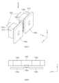
도 5는 일 실시 예에 따른 카메라 모듈의 AF 자석 부재 및 AF 코일을 나타내는 도면이다.FIG. 5 is a drawing showing an AF magnet member and an AF coil of a camera module according to one embodiment.
도 5를 참조하면, 501은 카메라 모듈(예: 카메라 모듈(10))의 AF 자석 부재(136), AF 코일(145) 및 AF 위치 센서(147)의 위치 관계를 나타내는 사시도이고, 502는 501의 AF 자석 부재(136), AF 코일(145) 및 AF 위치 센서(147)를 B방향에서 바라본 평면도이다.Referring to FIG. 5, 501 is a perspective view showing the positional relationship of an AF magnet member (136), an AF coil (145), and an AF position sensor (147) of a camera module (e.g., camera module (10)), and 502 is a plan view of the AF magnet member (136), the AF coil (145), and the AF position sensor (147) of 501 as viewed from the B direction.
일 실시 예에 따르면, AF 자석 부재(136)는 하나의 축(예: Z축) 방향으로 제1 진퇴 운동(510)을 수행할 수 있다. 예를 들면, 프로세서(예: 카메라 모듈(10)의 구동과 관련한 제1 프로세서(또는 제어 회로) 또는 카메라 모듈(10)이 안착되는 전자 장치의 제2 프로세서)는 AF 코일(145)에 지정된 크기의 신호(예: 지정된 크기의 전류)를 공급할 수 있다. 상기 프로세서는 AF 위치 센서(147)로부터 센싱 값을 수신하고, 이에 대응하는 신호를 AF 코일(145)에 공급할 수 있다. AF 코일(145)은 수신된 신호에 따라 지정된 방향 및 지정된 크기의 자기장을 생성하고, 생성된 자기장에 따라 AF 자석 부재(136)는 제1 진퇴 운동(510)을 수행할 수 있다.According to one embodiment, the AF magnet member (136) can perform a first forward and backward movement (510) in the direction of one axis (e.g., the Z-axis). For example, a processor (e.g., a first processor (or a control circuit) related to driving the camera module (10) or a second processor of an electronic device on which the camera module (10) is mounted) can supply a signal of a specified size (e.g., a current of a specified size) to the AF coil (145). The processor can receive a sensing value from an AF position sensor (147) and supply a signal corresponding thereto to the AF coil (145). The AF coil (145) generates a magnetic field of a specified direction and a specified size according to the received signal, and the AF magnet member (136) can perform the first forward and backward movement (510) according to the generated magnetic field.
일 실시 예에 따라, B방향에서 바라보면, AF 위치 센서(147)는 AF 코일(145)의 일측(예: X축 방향의 일측)에 배치될 수 있다. 또한, AF 위치 센서(147)는 AF 자석 부재(136)의 일측(예: X축 방향의 일측)에 배치될 수 있다. AF 코일(145) 및 AF 자석 부재(136)는 Y축 방향으로 바라보면 중첩될 수 있다(또는 대면하여 배치될 수 있다). X축 방향(예: AF 코일(145)과 간격이 일정하게 유지되는 방향)으로 AF 자석 부재(136)의 가상의 연장 영역(520)을 가정하면, AF 위치 센서(147)의 적어도 일부는 가상의 연장 영역(520)과 중첩될 수 있다. 또는 X축 방향으로 바라보면, AF 위치 센서(147)의 적어도 일부는 AF 자석 부재(136)와 중첩될 수 있다.According to one embodiment, when viewed from the B direction, the AF position sensor (147) may be disposed on one side of the AF coil (145) (e.g., one side in the X-axis direction). Additionally, the AF position sensor (147) may be disposed on one side of the AF magnet member (136) (e.g., one side in the X-axis direction). The AF coil (145) and the AF magnet member (136) may overlap (or face each other) when viewed in the Y-axis direction. Assuming a virtual extension area (520) of the AF magnet member (136) in the X-axis direction (e.g., a direction in which a distance from the AF coil (145) is maintained constant), at least a portion of the AF position sensor (147) may overlap with the virtual extension area (520). Alternatively, when viewed in the X-axis direction, at least a portion of the AF position sensor (147) may overlap with the AF magnet member (136).
도 6은 일 실시 예에 따른 카메라 모듈의 제1 자석 부재, 제2 자석 부재, 제1 코일 및 제2 코일을 나타내는 도면이다.FIG. 6 is a drawing showing a first magnet member, a second magnet member, a first coil, and a second coil of a camera module according to one embodiment.
도 6을 참조하면, 601은 카메라 모듈(예: 카메라 모듈(10))의 제1 자석 부재(135a), 제2 자석 부재(135b), 제1 코일(144a), 제2 코일(144b) 및 제1 위치 센서(146a)의 위치 관계를 나타내는 사시도이고, 602는 601의 제1 자석 부재(135a), 제2 자석 부재(135b), 제1 코일(144a), 제2 코일(144b) 및 제1 위치 센서(146a)를 B방향에서 바라본 평면도이다.Referring to FIG. 6, 601 is a perspective view showing the positional relationship of a first magnet member (135a), a second magnet member (135b), a first coil (144a), a second coil (144b), and a first position sensor (146a) of a camera module (e.g., camera module (10)), and 602 is a plan view of the first magnet member (135a), the second magnet member (135b), the first coil (144a), the second coil (144b), and the first position sensor (146a) of 601 as viewed from the B direction.
일 실시 예에 따르면, 제1 자석 부재(135a) 및 제2 자석 부재(135b)는 2개의 축(예: X축 및 Y축) 방향으로 제2 진퇴 운동(610) 및 제3 진퇴 운동(620)을 수행할 수 있다. 예를 들면, 프로세서(예: 카메라 모듈(10)의 구동과 관련한 제1 프로세서(또는 제어 회로) 또는 카메라 모듈(10)이 안착되는 전자 장치의 제2 프로세서)는 제1 코일(144a) 및 제2 코일(144b)에 지정된 크기의 신호(예: 지정된 크기의 전류)를 공급할 수 있다. 상기 프로세서는 제1 위치 센서(146a)로부터 센싱 값을 수신하고, 이에 대응하는 신호를 제1 코일(144a) 및 제2 코일(144b)에 공급할 수 있다. 제1 코일(144a) 및 제2 코일(144b)은 수신된 신호에 따라 지정된 방향 및 지정된 크기의 자기장을 생성하고, 생성된 자기장에 따라 제1 자석 부재(135a) 및 제2 자석 부재(135b)는 제2 진퇴 운동(610)을 수행할 수 있다.According to one embodiment, the first magnet member (135a) and the second magnet member (135b) can perform a second forward/backward movement (610) and a third forward/backward movement (620) in two axes (e.g., X-axis and Y-axis) directions. For example, a processor (e.g., a first processor (or control circuit) related to driving of the camera module (10) or a second processor of an electronic device on which the camera module (10) is mounted) can supply a signal of a specified size (e.g., a current of a specified size) to the first coil (144a) and the second coil (144b). The processor can receive a sensing value from the first position sensor (146a) and supply a signal corresponding thereto to the first coil (144a) and the second coil (144b). The first coil (144a) and the second coil (144b) generate a magnetic field of a specified direction and a specified size according to the received signal, and the first magnet member (135a) and the second magnet member (135b) can perform a second forward/reverse motion (610) according to the generated magnetic field.
또한, 도 1 내지 도 4를 참조하면, 제3 자석 부재(135c) 및 제4 자석 부재(135d)는 제1 자석 부재(135a) 및 제2 자석 부재(135b)와 유사하게 제3 진퇴 운동(620)을 수행할 수 있다. 예컨대, 상기 프로세서는 제3 코일(144c) 및 제4 코일(144d)에 지정된 크기의 신호를 공급하고, 제3 코일(144c) 및 제4 코일(144d)은 수신된 신호에 따라 지정된 방향 및 지정된 크기의 자기장을 생성하고, 생성된 자기장에 따라 제3 자석 부재(135c) 및 제4 자석 부재(135d)는 제3 진퇴 운동(620)을 수행할 수 있다. 제1 자석 부재(135a), 제2 자석 부재(135b), 제3 자석 부재(135c) 및 제4 자석 부재(135d)는 제1 캐리어(132)에 고정되어 있고, 제3 자석 부재(135c) 및 제4 자석 부재(135d)가 제3 진퇴 운동(620)을 수행하면, 제1 자석 부재(135a) 및 제2 자석 부재(135b)도 제1 캐리어(132)를 통해 제3 진퇴 운동(620)을 수행할 수 있다. 따라서, 제1 자석 부재(135a) 및 제2 자석 부재(135b)는 Y방향으로 제2 진퇴 운동(610)(예: 제1 자석 부재(135a) 및 제2 자석 부재(135b)에 의한 진퇴 운동)을 수행하고, X방향으로 제3 진퇴 운동(620)(예: 제3 자석 부재(135c) 및 제4 자석 부재(135d)에 의한 진퇴 운동)을 수행할 수 있다. 이와 유사하게, 제3 자석 부재(135c) 및 제4 자석 부재(135d)도 Y방향으로 제2 진퇴 운동(610)을 수행하고, X방향으로 제3 진퇴 운동(620)을 수행할 수 있다.In addition, referring to FIGS. 1 to 4, the third magnet member (135c) and the fourth magnet member (135d) can perform the third forward and backward movement (620) similarly to the first magnet member (135a) and the second magnet member (135b). For example, the processor supplies a signal of a specified size to the third coil (144c) and the fourth coil (144d), and the third coil (144c) and the fourth coil (144d) generate a magnetic field of a specified direction and a specified size according to the received signal, and the third magnet member (135c) and the fourth magnet member (135d) can perform the third forward and backward movement (620) according to the generated magnetic field. The first magnet member (135a), the second magnet member (135b), the third magnet member (135c), and the fourth magnet member (135d) are fixed to the first carrier (132), and when the third magnet member (135c) and the fourth magnet member (135d) perform the third forward and backward movement (620), the first magnet member (135a) and the second magnet member (135b) can also perform the third forward and backward movement (620) via the first carrier (132). Accordingly, the first magnet member (135a) and the second magnet member (135b) can perform a second forward/backward movement (610) in the Y direction (e.g., forward/backward movement by the first magnet member (135a) and the second magnet member (135b)) and a third forward/backward movement (620) in the X direction (e.g., forward/backward movement by the third magnet member (135c) and the fourth magnet member (135d)). Similarly, the third magnet member (135c) and the fourth magnet member (135d) can also perform a second forward/backward movement (610) in the Y direction and a third forward/backward movement (620) in the X direction.
일 실시 예에 따라, B방향에서 바라보면, 제1 위치 센서(146a)는 제1 자석 부재(135a) 및 제2 자석 부재(135b)의 사이에 배치될 수 있다. 또한, 제1 위치 센서(146a)는 제1 코일(144a) 및 제2 코일(144b)의 사이에 배치될 수 있다. 제1 자석 부재(135a) 및 제1 코일(144a)은 Y축 방향으로 바라보면 중첩될 수 있다. 제2 자석 부재(135b) 및 제2 코일(144b)은 Y축 방향으로 바라보면 중첩될 수 있다. X축 방향(예: 제1 자석 부재(135a) 또는 제2 자석 부재(135b)와 특정 간격이 일정하게 유지되는 방향)으로 제1 자석 부재(135a) 또는 제2 자석 부재(135b)의 가상의 연장 영역(630)을 가정하면, 제1 위치 센서(146a)의 적어도 일부는 가상의 연장 영역(630)과 중첩될 수 있다. 또는 X축 방향으로 바라보면, 제1 위치 센서(146a)의 적어도 일부는 제1 자석 부재(135a) 또는 제2 자석 부재(135b)와 중첩될 수 있다. 이와 유사하게, 제2 위치 센서(146b)는 제3 자석 부재(135c) 및 제4 자석 부재(135d)의 사이에 배치될 수 있다. 또한, 제2 위치 센서(146b)는 제3 코일(144c) 및 제4 코일(144d)의 사이에 배치될 수 있다. 제3 자석 부재(135c) 및 제3 코일(144c)은 X축 방향으로 바라보면 중첩될 수 있다. 제4 자석 부재(135d) 및 제4 코일(144d)은 X축 방향으로 바라보면 중첩될 수 있다. Y축 방향(예: 제3 자석 부재(135c) 또는 제4 자석 부재(135d)와 특정 간격이 일정하게 유지되는 방향)으로 제3 자석 부재(135c) 또는 제4 자석 부재(135d)의 가상의 연장 영역을 가정하면, 제2 위치 센서(146b)의 적어도 일부는 가상의 연장 영역과 중첩될 수 있다. 또는 Y축 방향으로 바라보면, 제2 위치 센서(146b)의 적어도 일부는 제3 자석 부재(135c) 또는 제4 자석 부재(135d)와 중첩될 수 있다.According to one embodiment, when viewed from the B direction, the first position sensor (146a) may be disposed between the first magnet member (135a) and the second magnet member (135b). Additionally, the first position sensor (146a) may be disposed between the first coil (144a) and the second coil (144b). The first magnet member (135a) and the first coil (144a) may overlap when viewed in the Y-axis direction. The second magnet member (135b) and the second coil (144b) may overlap when viewed in the Y-axis direction. Assuming a virtual extension area (630) of the first magnet member (135a) or the second magnet member (135b) in the X-axis direction (e.g., a direction in which a specific distance is constantly maintained from the first magnet member (135a) or the second magnet member (135b), at least a portion of the first position sensor (146a) may overlap with the virtual extension area (630). Alternatively, when viewed in the X-axis direction, at least a portion of the first position sensor (146a) may overlap with the first magnet member (135a) or the second magnet member (135b). Similarly, the second position sensor (146b) may be disposed between the third magnet member (135c) and the fourth magnet member (135d). Additionally, the second position sensor (146b) may be disposed between the third coil (144c) and the fourth coil (144d). The third magnet member (135c) and the third coil (144c) may overlap when viewed in the X-axis direction. The fourth magnet member (135d) and the fourth coil (144d) may overlap when viewed in the X-axis direction. Assuming a virtual extension area of the third magnet member (135c) or the fourth magnet member (135d) in the Y-axis direction (e.g., a direction in which a specific distance from the third magnet member (135c) or the fourth magnet member (135d) is constantly maintained), at least a portion of the second position sensor (146b) may overlap with the virtual extension area. Alternatively, when viewed in the Y-axis direction, at least a portion of the second position sensor (146b) may overlap with the third magnet member (135c) or the fourth magnet member (135d).
도 7은 일 실시 예에 따른 카메라 모듈의 제1 위치 센서 또는 제2 위치 센서의 조립 오차를 보정하는 방법을 나타내는 도면이다. 도 8은, 도 7의 제1 위치 센서 또는 제2 위치 센서에 의해 측정된 자기력의 크기의 일 예를 나타내는 그래프이다. 예를 들면, 제1 위치 센서(146a)가 제1 자석 부재(135a) 및 제2 자석 부재(135b)의 정확히 중간에 위치할수록, 제1 자석 부재(135a) 및 제2 자석 부재(135b)의 위치는 정확하게 측정될 수 있다. 또한, 제2 위치 센서(146b)가 제3 자석 부재(135c) 및 제4 자석 부재(135d)의 정확히 중간에 위치할수록, 제3 자석 부재(135c) 및 제4 자석 부재(135d)의 위치는 정확하게 측정될 수 있다. 하지만, 조립 과정에서, 제1 위치 센서(146a)는 제1 자석 부재(135a) 또는 제2 자석 부재(135b) 중 하나에 가깝게 배치(예: 조립 오차)될 수 있다. 또는 제2 위치 센서(146b)는 제3 자석 부재(135c) 또는 제4 자석 부재(135d) 중 하나에 가깝게 배치(예: 조립 오차)될 수 있다. 따라서, 제1 위치 센서(146a) 또는 제2 위치 센서(146b)의 조립 오차에 대한 보정이 필요할 수 있다.FIG. 7 is a drawing showing a method for correcting an assembly error of a first position sensor or a second position sensor of a camera module according to one embodiment. FIG. 8 is a graph showing an example of a magnitude of a magnetic force measured by the first position sensor or the second position sensor of FIG. 7. For example, the closer the first position sensor (146a) is to the exact middle of the first magnet member (135a) and the second magnet member (135b), the more accurately the positions of the first magnet member (135a) and the second magnet member (135b) can be measured. In addition, the closer the second position sensor (146b) is to the exact middle of the third magnet member (135c) and the fourth magnet member (135d), the more accurately the positions of the third magnet member (135c) and the fourth magnet member (135d) can be measured. However, during the assembly process, the first position sensor (146a) may be positioned close to one of the first magnet member (135a) or the second magnet member (135b) (e.g., due to an assembly error). Or, the second position sensor (146b) may be positioned close to one of the third magnet member (135c) or the fourth magnet member (135d) (e.g., due to an assembly error). Accordingly, compensation for the assembly error of the first position sensor (146a) or the second position sensor (146b) may be required.
일 실시 예에 따르면, 제1 위치 센서(146a)는 조립 과정에서 제1 자석 부재(135a)보다 제2 자석 부재(135b)에 더 가깝게 배치될 수 있다. 예를 들면, 제1 자석 부재(135a)와 제1 위치 센서(146a) 사이의 거리(P+α)는 제1 기준 거리(P)와 제1 조립 오차(α)를 합한 거리일 수 있다. 제2 자석 부재(135b)와 제1 위치 센서(146a) 사이의 거리(P-α)는 제1 기준 거리(P)에서 제1 조립 오차(α)를 뺀 거리일 수 있다. 여기서 제1 기준 거리(P)는 제1 자석 부재(135a)와 제2 자석 부재(135b) 사이 거리의 절반을 의미한다.According to one embodiment, the first position sensor (146a) may be arranged closer to the second magnet member (135b) than to the first magnet member (135a) during the assembly process. For example, the distance (P+α) between the first magnet member (135a) and the first position sensor (146a) may be a distance that is the sum of the first reference distance (P) and the first assembly error (α). The distance (P-α) between the second magnet member (135b) and the first position sensor (146a) may be a distance that is the first reference distance (P) minus the first assembly error (α). Here, the first reference distance (P) means half of the distance between the first magnet member (135a) and the second magnet member (135b).
다양한 실시 예에 따르면, 제2 위치 센서(146b)는 조립 과정에서 제4 자석 부재(135d)보다 제3 자석 부재(135c)에 더 가깝게 배치될 수 있다. 예를 들면, 제3 자석 부재(135c)와 제2 위치 센서(146b) 사이의 거리(Q-β)는 제2 기준 거리(Q)에서 제2 조립 오차(β)를 뺀 거리일 수 있다. 제4 자석 부재(135d)와 제2 위치 센서(146b) 사이의 거리(Q+β)는 제2 기준 거리(Q)와 제2 조립 오차(β)를 합한 거리일 수 있다. 여기서 제2 기준 거리(Q)는 제3 자석 부재(135c)와 제4 자석 부재(135d) 사이 거리의 절반을 의미한다.According to various embodiments, the second position sensor (146b) may be arranged closer to the third magnet member (135c) than to the fourth magnet member (135d) during the assembly process. For example, the distance (Q-β) between the third magnet member (135c) and the second position sensor (146b) may be a distance obtained by subtracting a second assembly error (β) from the second reference distance (Q). The distance (Q+β) between the fourth magnet member (135d) and the second position sensor (146b) may be a distance obtained by adding the second reference distance (Q) and the second assembly error (β). Here, the second reference distance (Q) means half of the distance between the third magnet member (135c) and the fourth magnet member (135d).
일 실시 예에 따르면, 프로세서(예: 카메라 모듈(10)의 구동과 관련한 제1 프로세서(또는 제어 회로) 또는 카메라 모듈(10)이 안착되는 전자 장치의 제2 프로세서)는, Y축 방향의 움직임을 제한한 상태에서 X축 방향으로 제1 캐리어(132)를 이동시키고, 제1 위치 센서(146a)를 통해 제1 자석 부재(135a) 및 제2 자석 부재(135b)에 의해 형성된 자기장의 크기를 측정(또는 스캔)할 수 있다. 또는 상기 프로세서는, X축 방향의 움직임을 제한한 상태에서 Y축 방향으로 제1 캐리어(132)를 이동시키고, 제2 위치 센서(146b)를 통해 제3 자석 부재(135c) 및 제4 자석 부재(135d)에 의해 형성된 자기장의 크기를 측정(또는 스캔)할 수 있다. 제1 위치 센서(146a) 또는 제2 위치 센서(146b)에 의해 측정된 자기장의 크기는 도 8의 그래프와 같은 형태를 가질 수 있다. 조립 오차가 없다면, 도 8의 그래프에서 거리가 0인 지점(예: 제1 기준 거리(P) 또는 제2 기준 거리(Q))에서 자기장의 크기는 최대값(MAX)을 가질 수 있다. 그러나, 조립 오차(예: 제1 조립 오차(α) 또는 제2 조립 오차(β))가 존재하면, 자기장의 크기가 최대값(MAX)을 가지는 지점은 도 8의 그래프에서 거리가 0인 지점의 좌측 또는 우측에 나타날 수 있다. 자기장의 크기가 최대값(MAX)을 가지는 지점과 거리가 0인 지점 사이의 오프셋 거리(DO)는 조립 오차(예: 제1 조립 오차(α) 또는 제2 조립 오차(β))와 동일할 수 있다. 상기 프로세서는 제1 위치 센서(146a) 또는 제2 위치 센서(146b)에 대응하는 오프셋 거리(DO)를 메모리(예: 제1 위치 센서(146a) 또는 제2 위치 센서(146b)에 포함된 메모리, 또는 후술되는 메모리(930))에 저장하고, 제1 자석 부재(135a) 및 제2 자석 부재(135b)의 위치 또는 제3 자석 부재(135c) 및 제4 자석 부재(135d)의 위치 판단 시 오프셋 거리(DO)를 보상할 수 있다.According to one embodiment, a processor (e.g., a first processor (or control circuit) related to driving a camera module (10) or a second processor of an electronic device on which a camera module (10) is mounted) may move the first carrier (132) in the X-axis direction while restricting its movement in the Y-axis direction, and measure (or scan) the magnitude of a magnetic field formed by the first magnetic member (135a) and the second magnetic member (135b) through the first position sensor (146a). Alternatively, the processor may move the first carrier (132) in the Y-axis direction while restricting its movement in the X-axis direction, and measure (or scan) the magnitude of a magnetic field formed by the third magnetic member (135c) and the fourth magnetic member (135d) through the second position sensor (146b). The magnitude of the magnetic field measured by the first position sensor (146a) or the second position sensor (146b) may have a form like the graph of FIG. 8. If there is no assembly error, the magnitude of the magnetic field can have a maximum value (MAX) at a point where the distance is 0 (e.g., the first reference distance (P) or the second reference distance (Q)) in the graph of Fig. 8. However, if an assembly error (e.g., the first assembly error (α) or the second assembly error (β)) exists, the point where the magnitude of the magnetic field has a maximum value (MAX) may appear to the left or right of the point where the distance is 0 in the graph of Fig. 8. The offset distance (DO) between the point where the magnitude of the magnetic field has a maximum value (MAX) and the point where the distance is 0 may be equal to the assembly error (e.g., the first assembly error (α) or the second assembly error (β)). The above processor can store an offset distance (DO) corresponding to the first position sensor (146a) or the second position sensor (146b) in a memory (e.g., a memory included in the first position sensor (146a) or the second position sensor (146b), or a memory (930) described below), and compensate for the offset distance (DO) when determining the positions of the first magnet member (135a) and the second magnet member (135b) or the positions of the third magnet member (135c) and the fourth magnet member (135d).
도 9은, 다양한 실시 예들에 따른, 네트워크 환경(900) 내의 전자 장치(901)의 블럭도이다. 도 9을 참조하면, 네트워크 환경(900)에서 전자 장치(901)는 제1 네트워크(998)(예: 근거리 무선 통신 네트워크)를 통하여 전자 장치(902)와 통신하거나, 또는 제2 네트워크(999)(예: 원거리 무선 통신 네트워크)를 통하여 전자 장치(904) 또는 서버(908)와 통신할 수 있다. 일 실시 예에 따르면, 전자 장치(901)는 서버(908)를 통하여 전자 장치(904)와 통신할 수 있다. 일 실시 예에 따르면, 전자 장치(901)는 프로세서(920), 메모리(930), 입력 장치(950), 음향 출력 장치(955), 표시 장치(960), 오디오 모듈(970), 센서 모듈(976), 인터페이스(977), 햅틱 모듈(979), 카메라 모듈(980), 전력 관리 모듈(988), 배터리(989), 통신 모듈(990), 가입자 식별 모듈(996), 또는 안테나 모듈(997)을 포함할 수 있다. 어떤 실시 예에서는, 전자 장치(901)에는, 이 구성요소들 중 적어도 하나(예: 표시 장치(960) 또는 카메라 모듈(980))가 생략되거나, 하나 이상의 다른 구성요소가 추가될 수 있다. 어떤 실시 예에서는, 이 구성요소들 중 일부들은 하나의 통합된 회로로 구현될 수 있다. 예를 들면, 센서 모듈(976)(예: 지문 센서, 홍채 센서, 또는 조도 센서)은 표시 장치(960)(예: 디스플레이)에 임베디드된 채 구현될 수 있다FIG. 9 is a block diagram of an electronic device (901) in a network environment (900) according to various embodiments. Referring to FIG. 9, in the network environment (900), the electronic device (901) may communicate with the electronic device (902) through a first network (998) (e.g., a short-range wireless communication network), or may communicate with the electronic device (904) or the server (908) through a second network (999) (e.g., a long-range wireless communication network). According to one embodiment, the electronic device (901) may communicate with the electronic device (904) through the server (908). According to one embodiment, the electronic device (901) may include a processor (920), a memory (930), an input device (950), an audio output device (955), a display device (960), an audio module (970), a sensor module (976), an interface (977), a haptic module (979), a camera module (980), a power management module (988), a battery (989), a communication module (990), a subscriber identification module (996), or an antenna module (997). In some embodiments, the electronic device (901) may omit at least one of these components (e.g., the display device (960) or the camera module (980)), or may have one or more other components added. In some embodiments, some of these components may be implemented as a single integrated circuit. For example, a sensor module (976) (e.g., a fingerprint sensor, an iris sensor, or an ambient light sensor) may be implemented embedded in a display device (960) (e.g., a display).
프로세서(920)는, 예를 들면, 소프트웨어(예: 프로그램(940))를 실행하여 프로세서(920)에 연결된 전자 장치(901)의 적어도 하나의 다른 구성요소(예: 하드웨어 또는 소프트웨어 구성요소)를 제어할 수 있고, 다양한 데이터 처리 또는 연산을 수행할 수 있다. 일 실시 예에 따르면, 데이터 처리 또는 연산의 적어도 일부로서, 프로세서(920)는 다른 구성요소(예: 센서 모듈(976) 또는 통신 모듈(990))로부터 수신된 명령 또는 데이터를 휘발성 메모리(932)에 로드하고, 휘발성 메모리(932)에 저장된 명령 또는 데이터를 처리하고, 결과 데이터를 비휘발성 메모리(934)에 저장할 수 있다. 일 실시 예에 따르면, 프로세서(920)는 메인 프로세서(921)(예: 중앙 처리 장치 또는 어플리케이션 프로세서), 및 이와는 독립적으로 또는 함께 운영 가능한 보조 프로세서(923)(예: 그래픽 처리 장치, 이미지 시그널 프로세서, 센서 허브 프로세서, 또는 커뮤니케이션 프로세서)를 포함할 수 있다. 추가적으로 또는 대체적으로, 보조 프로세서(923)는 메인 프로세서(921)보다 저전력을 사용하거나, 또는 지정된 기능에 특화되도록 설정될 수 있다. 보조 프로세서(923)는 메인 프로세서(921)와 별개로, 또는 그 일부로서 구현될 수 있다.The processor (920) may control at least one other component (e.g., a hardware or software component) of the electronic device (901) connected to the processor (920) by executing, for example, software (e.g., a program (940)), and may perform various data processing or calculations. According to one embodiment, as at least a part of the data processing or calculation, the processor (920) may load a command or data received from another component (e.g., a sensor module (976) or a communication module (990)) into a volatile memory (932), process the command or data stored in the volatile memory (932), and store result data in a non-volatile memory (934). According to one embodiment, the processor (920) may include a main processor (921) (e.g., a central processing unit or an application processor), and a secondary processor (923) (e.g., a graphic processing unit, an image signal processor, a sensor hub processor, or a communication processor) that may operate independently or together therewith. Additionally or alternatively, the auxiliary processor (923) may be configured to use less power than the main processor (921), or to be specialized for a given function. The auxiliary processor (923) may be implemented separately from the main processor (921), or as part of it.
보조 프로세서(923)는, 예를 들면, 메인 프로세서(921)가 인액티브(예: 슬립) 상태에 있는 동안 메인 프로세서(921)를 대신하여, 또는 메인 프로세서(921)가 액티브(예: 어플리케이션 실행) 상태에 있는 동안 메인 프로세서(921)와 함께, 전자 장치(901)의 구성요소들 중 적어도 하나의 구성요소(예: 표시 장치(960), 센서 모듈(976), 또는 통신 모듈(990))와 관련된 기능 또는 상태들의 적어도 일부를 제어할 수 있다. 일 실시 예에 따르면, 보조 프로세서(923)(예: 이미지 시그널 프로세서 또는 커뮤니케이션 프로세서)는 기능적으로 관련 있는 다른 구성 요소(예: 카메라 모듈(980) 또는 통신 모듈(990))의 일부로서 구현될 수 있다.The auxiliary processor (923) may control at least a portion of functions or states associated with at least one of the components of the electronic device (901) (e.g., the display device (960), the sensor module (976), or the communication module (990)), for example, on behalf of the main processor (921) while the main processor (921) is in an inactive (e.g., sleep) state, or together with the main processor (921) while the main processor (921) is in an active (e.g., application execution) state. In one embodiment, the auxiliary processor (923) (e.g., an image signal processor or a communication processor) may be implemented as a part of another functionally related component (e.g., a camera module (980) or a communication module (990)).
메모리(930)는, 전자 장치(901)의 적어도 하나의 구성요소(예: 프로세서(920) 또는 센서 모듈(976))에 의해 사용되는 다양한 데이터를 저장할 수 있다. 데이터는, 예를 들어, 소프트웨어(예: 프로그램(940)) 및, 이와 관련된 명령에 대한 입력 데이터 또는 출력 데이터를 포함할 수 있다. 메모리(930)는, 휘발성 메모리(932) 또는 비휘발성 메모리(934)를 포함할 수 있다.The memory (930) can store various data used by at least one component (e.g., the processor (920) or the sensor module (976)) of the electronic device (901). The data can include, for example, software (e.g., the program (940)) and input data or output data for commands related thereto. The memory (930) can include a volatile memory (932) or a nonvolatile memory (934).
프로그램(940)은 메모리(930)에 소프트웨어로서 저장될 수 있으며, 예를 들면, 운영 체제(942), 미들 웨어(944) 또는 어플리케이션(946)을 포함할 수 있다.The program (940) may be stored as software in memory (930) and may include, for example, an operating system (942), middleware (944), or an application (946).
입력 장치(950)는, 전자 장치(901)의 구성요소(예: 프로세서(920))에 사용될 명령 또는 데이터를 전자 장치(901)의 외부(예: 사용자)로부터 수신할 수 있다. 입력 장치(950)는, 예를 들면, 마이크, 마우스, 키보드, 또는 디지털 펜(예: 스타일러스 펜)을 포함할 수 있다.The input device (950) can receive commands or data to be used for a component of the electronic device (901) (e.g., a processor (920)) from an external source (e.g., a user) of the electronic device (901). The input device (950) can include, for example, a microphone, a mouse, a keyboard, or a digital pen (e.g., a stylus pen).
음향 출력 장치(955)는 음향 신호를 전자 장치(901)의 외부로 출력할 수 있다. 음향 출력 장치(955)는, 예를 들면, 스피커 또는 리시버를 포함할 수 있다. 스피커는 멀티미디어 재생 또는 녹음 재생과 같이 일반적인 용도로 사용될 수 있고, 리시버는 착신 전화를 수신하기 위해 사용될 수 있다. 일 실시 예에 따르면, 리시버는 스피커와 별개로, 또는 그 일부로서 구현될 수 있다.The audio output device (955) can output an audio signal to the outside of the electronic device (901). The audio output device (955) can include, for example, a speaker or a receiver. The speaker can be used for general purposes such as multimedia playback or recording playback, and the receiver can be used to receive an incoming call. According to one embodiment, the receiver can be implemented separately from the speaker or as a part thereof.
표시 장치(960)는 전자 장치(901)의 외부(예: 사용자)로 정보를 시각적으로 제공할 수 있다. 표시 장치(960)는, 예를 들면, 디스플레이, 홀로그램 장치, 또는 프로젝터 및 해당 장치를 제어하기 위한 제어 회로를 포함할 수 있다. 일 실시 예에 따르면, 표시 장치(960)는 터치를 감지하도록 설정된 터치 회로(touch circuitry), 또는 상기 터치에 의해 발생되는 힘의 세기를 측정하도록 설정된 센서 회로(예: 압력 센서)를 포함할 수 있다.The display device (960) can visually provide information to an external party (e.g., a user) of the electronic device (901). The display device (960) can include, for example, a display, a holographic device, or a projector and a control circuit for controlling the device. According to one embodiment, the display device (960) can include touch circuitry configured to detect a touch, or a sensor circuitry configured to measure a strength of a force generated by the touch (e.g., a pressure sensor).
오디오 모듈(970)은 소리를 전기 신호로 변환시키거나, 반대로 전기 신호를 소리로 변환시킬 수 있다. 일 실시 예에 따르면, 오디오 모듈(970)은, 입력 장치(950)를 통해 소리를 획득하거나, 음향 출력 장치(955), 또는 전자 장치(901)와 직접 또는 무선으로 연결된 외부 전자 장치(예: 전자 장치(902))(예: 스피커 또는 헤드폰)를 통해 소리를 출력할 수 있다.The audio module (970) can convert sound into an electrical signal, or vice versa, convert an electrical signal into sound. According to one embodiment, the audio module (970) can obtain sound through an input device (950), or output sound through an audio output device (955), or an external electronic device (e.g., an electronic device (902)) (e.g., a speaker or a headphone) directly or wirelessly connected to the electronic device (901).
센서 모듈(976)은 전자 장치(901)의 작동 상태(예: 전력 또는 온도), 또는 외부의 환경 상태(예: 사용자 상태)를 감지하고, 감지된 상태에 대응하는 전기 신호 또는 데이터 값을 생성할 수 있다. 일 실시 예에 따르면, 센서 모듈(976)은, 예를 들면, 제스처 센서, 자이로 센서, 기압 센서, 마그네틱 센서, 가속도 센서, 그립 센서, 근접 센서, 컬러 센서, IR(infrared) 센서, 생체 센서, 온도 센서, 습도 센서, 또는 조도 센서를 포함할 수 있다.The sensor module (976) can detect an operating state (e.g., power or temperature) of the electronic device (901) or an external environmental state (e.g., user state) and generate an electric signal or data value corresponding to the detected state. According to one embodiment, the sensor module (976) can include, for example, a gesture sensor, a gyro sensor, a barometric pressure sensor, a magnetic sensor, an acceleration sensor, a grip sensor, a proximity sensor, a color sensor, an IR (infrared) sensor, a biometric sensor, a temperature sensor, a humidity sensor, or an illuminance sensor.
인터페이스(977)는 전자 장치(901)가 외부 전자 장치(예: 전자 장치(902))와 직접 또는 무선으로 연결되기 위해 사용될 수 있는 하나 이상의 지정된 프로토콜들을 지원할 수 있다. 일 실시 예에 따르면, 인터페이스(977)는, 예를 들면, HDMI(high definition multimedia interface), USB(universal serial bus) 인터페이스, SD카드 인터페이스, 또는 오디오 인터페이스를 포함할 수 있다.The interface (977) may support one or more designated protocols that may be used to allow the electronic device (901) to directly or wirelessly connect with an external electronic device (e.g., the electronic device (902)). In one embodiment, the interface (977) may include, for example, a high definition multimedia interface (HDMI), a universal serial bus (USB) interface, an SD card interface, or an audio interface.
연결 단자(978)는, 그를 통해서 전자 장치(901)가 외부 전자 장치(예: 전자 장치(902))와 물리적으로 연결될 수 있는 커넥터를 포함할 수 있다. 일 실시 예에 따르면, 연결 단자(978)는, 예를 들면, HDMI 커넥터, USB 커넥터, SD 카드 커넥터, 또는 오디오 커넥터(예: 헤드폰 커넥터)를 포함할 수 있다.The connection terminal (978) may include a connector through which the electronic device (901) may be physically connected to an external electronic device (e.g., the electronic device (902)). According to one embodiment, the connection terminal (978) may include, for example, an HDMI connector, a USB connector, an SD card connector, or an audio connector (e.g., a headphone connector).
햅틱 모듈(979)은 전기적 신호를 사용자가 촉각 또는 운동 감각을 통해서 인지할 수 있는 기계적인 자극(예: 진동 또는 움직임) 또는 전기적인 자극으로 변환할 수 있다. 일 실시 예에 따르면, 햅틱 모듈(979)은, 예를 들면, 모터, 압전 소자, 또는 전기 자극 장치를 포함할 수 있다.The haptic module (979) can convert an electrical signal into a mechanical stimulus (e.g., vibration or movement) or an electrical stimulus that a user can perceive through a tactile or kinesthetic sense. According to one embodiment, the haptic module (979) can include, for example, a motor, a piezoelectric element, or an electrical stimulation device.
카메라 모듈(980)은 정지 영상 및 동영상을 촬영할 수 있다. 일 실시 예에 따르면, 카메라 모듈(980)은 하나 이상의 렌즈들, 이미지 센서들, 이미지 시그널 프로세서들, 또는 플래시들을 포함할 수 있다.The camera module (980) can capture still images and videos. According to one embodiment, the camera module (980) can include one or more lenses, image sensors, image signal processors, or flashes.
전력 관리 모듈(988)은 전자 장치(901)에 공급되는 전력을 관리할 수 있다. 일 실시 예에 따르면, 전력 관리 모듈(988)은, 예를 들면, PMIC(power management integrated circuit)의 적어도 일부로서 구현될 수 있다.The power management module (988) can manage power supplied to the electronic device (901). According to one embodiment, the power management module (988) can be implemented as, for example, at least a part of a power management integrated circuit (PMIC).
배터리(989)는 전자 장치(901)의 적어도 하나의 구성요소에 전력을 공급할 수 있다. 일 실시 예에 따르면, 배터리(989)는, 예를 들면, 재충전 불가능한 1차 전지, 재충전 가능한 2차 전지 또는 연료 전지를 포함할 수 있다.The battery (989) can power at least one component of the electronic device (901). In one embodiment, the battery (989) can include, for example, a non-rechargeable primary battery, a rechargeable secondary battery, or a fuel cell.
통신 모듈(990)은 전자 장치(901)와 외부 전자 장치(예: 전자 장치(902), 전자 장치(904), 또는 서버(908))간의 직접(예: 유선) 통신 채널 또는 무선 통신 채널의 수립, 및 수립된 통신 채널을 통한 통신 수행을 지원할 수 있다. 통신 모듈(990)은 프로세서(920)(예: 어플리케이션 프로세서)와 독립적으로 운영되고, 직접(예: 유선) 통신 또는 무선 통신을 지원하는 하나 이상의 커뮤니케이션 프로세서를 포함할 수 있다. 일 실시 예에 따르면, 통신 모듈(990)은 무선 통신 모듈(992)(예: 셀룰러 통신 모듈, 근거리 무선 통신 모듈, 또는 GNSS(global navigation satellite system) 통신 모듈) 또는 유선 통신 모듈(994)(예: LAN(local area network) 통신 모듈, 또는 전력선 통신 모듈)을 포함할 수 있다. 이들 통신 모듈 중 해당하는 통신 모듈은 제1 네트워크(998)(예: 블루투스, WiFi direct 또는 IrDA(infrared data association) 같은 근거리 통신 네트워크) 또는 제2 네트워크(999)(예: 셀룰러 네트워크, 인터넷, 또는 컴퓨터 네트워크(예: LAN 또는 WAN)와 같은 원거리 통신 네트워크)를 통하여 외부 전자 장치(904)와 통신할 수 있다. 이런 여러 종류의 통신 모듈들은 하나의 구성요소(예: 단일 칩)로 통합되거나, 또는 서로 별도의 복수의 구성요소들(예: 복수 칩들)로 구현될 수 있다. 무선 통신 모듈(992)은 가입자 식별 모듈(996)에 저장된 가입자 정보(예: 국제 모바일 가입자 식별자(IMSI))를 이용하여 제1 네트워크(998) 또는 제2 네트워크(999)와 같은 통신 네트워크 내에서 전자 장치(901)를 확인 및 인증할 수 있다.The communication module (990) may support establishment of a direct (e.g., wired) communication channel or a wireless communication channel between the electronic device (901) and an external electronic device (e.g., the electronic device (902), the electronic device (904), or the server (908)), and performance of communication through the established communication channel. The communication module (990) may operate independently from the processor (920) (e.g., the application processor) and may include one or more communication processors that support direct (e.g., wired) communication or wireless communication. According to one embodiment, the communication module (990) may include a wireless communication module (992) (e.g., a cellular communication module, a short-range wireless communication module, or a global navigation satellite system (GNSS) communication module) or a wired communication module (994) (e.g., a local area network (LAN) communication module or a power line communication module). A corresponding communication module among these communication modules may communicate with an external electronic device (904) via a first network (998) (e.g., a short-range communication network such as Bluetooth, WiFi direct, or IrDA (infrared data association)) or a second network (999) (e.g., a long-range communication network such as a cellular network, the Internet, or a computer network (e.g., a LAN or WAN)). These various types of communication modules may be integrated into a single component (e.g., a single chip) or implemented as multiple separate components (e.g., multiple chips). The wireless communication module (992) may use subscriber information stored in the subscriber identification module (996) (e.g., an international mobile subscriber identity (IMSI)) to identify and authenticate the electronic device (901) within a communication network such as the first network (998) or the second network (999).
안테나 모듈(997)은 신호 또는 전력을 외부(예: 외부 전자 장치)로 송신하거나 외부로부터 수신할 수 있다. 일 실시 예에 따르면, 안테나 모듈(997)은 서브스트레이트(예: PCB) 위에 형성된 도전체 또는 도전성 패턴으로 이루어진 방사체를 포함하는 하나의 안테나를 포함할 수 있다. 일 실시 예에 따르면, 안테나 모듈(997)은 복수의 안테나들을 포함할 수 있다. 이런 경우, 제1 네트워크(998) 또는 제2 네트워크(999)와 같은 통신 네트워크에서 사용되는 통신 방식에 적합한 적어도 하나의 안테나가, 예를 들면, 통신 모듈(990)에 의하여 상기 복수의 안테나들로부터 선택될 수 있다. 신호 또는 전력은 상기 선택된 적어도 하나의 안테나를 통하여 통신 모듈(990)과 외부 전자 장치 간에 송신되거나 수신될 수 있다. 어떤 실시 예에 따르면, 방사체 이외에 다른 부품(예: RFIC)이 추가로 안테나 모듈(997)의 일부로 형성될 수 있다.The antenna module (997) can transmit or receive signals or power to or from an external device (e.g., an external electronic device). According to one embodiment, the antenna module (997) can include one antenna including a radiator formed of a conductor or a conductive pattern formed on a substrate (e.g., a PCB). According to one embodiment, the antenna module (997) can include a plurality of antennas. In this case, at least one antenna suitable for a communication method used in a communication network, such as the first network (998) or the second network (999), can be selected from the plurality of antennas by, for example, the communication module (990). A signal or power can be transmitted or received between the communication module (990) and the external electronic device through the selected at least one antenna. According to some embodiments, in addition to the radiator, another component (e.g., an RFIC) can be additionally formed as a part of the antenna module (997).
상기 구성요소들 중 적어도 일부는 주변 기기들간 통신 방식(예: 버스, GPIO(general purpose input and output), SPI(serial peripheral interface), 또는 MIPI(mobile industry processor interface))을 통해 서로 연결되고 신호(예: 명령 또는 데이터)를 상호간에 교환할 수 있다.At least some of the above components may be connected to each other and exchange signals (e.g., commands or data) with each other via a communication method between peripheral devices (e.g., a bus, a general purpose input and output (GPIO), a serial peripheral interface (SPI), or a mobile industry processor interface (MIPI)).
일 실시 예에 따르면, 명령 또는 데이터는 제2 네트워크(999)에 연결된 서버(908)를 통해서 전자 장치(901)와 외부의 전자 장치(904)간에 송신 또는 수신될 수 있다. 외부 전자 장치(902, 904) 각각은 전자 장치(901)와 동일한 또는 다른 종류의 장치일 수 있다. 일 실시 예에 따르면, 전자 장치(901)에서 실행되는 동작들의 전부 또는 일부는 외부 전자 장치들(902, 904, 또는 908) 중 하나 이상의 외부 전자 장치들에서 실행될 수 있다. 예를 들면, 전자 장치(901)가 어떤 기능이나 서비스를 자동으로, 또는 사용자 또는 다른 장치로부터의 요청에 반응하여 수행해야 할 경우에, 전자 장치(901)는 기능 또는 서비스를 자체적으로 실행시키는 대신에 또는 추가적으로, 하나 이상의 외부 전자 장치들에게 그 기능 또는 그 서비스의 적어도 일부를 수행하라고 요청할 수 있다. 상기 요청을 수신한 하나 이상의 외부 전자 장치들은 요청된 기능 또는 서비스의 적어도 일부, 또는 상기 요청과 관련된 추가 기능 또는 서비스를 실행하고, 그 실행의 결과를 전자 장치(901)로 전달할 수 있다. 전자 장치(901)는 상기 결과를, 그대로 또는 추가적으로 처리하여, 상기 요청에 대한 응답의 적어도 일부로서 제공할 수 있다. 이를 위하여, 예를 들면, 클라우드 컴퓨팅, 분산 컴퓨팅, 또는 클라이언트-서버 컴퓨팅 기술이 이용될 수 있다.According to one embodiment, a command or data may be transmitted or received between the electronic device (901) and an external electronic device (904) via a server (908) connected to a second network (999). Each of the external electronic devices (902, 904) may be the same or a different type of device as the electronic device (901). According to one embodiment, all or part of the operations executed in the electronic device (901) may be executed in one or more of the external electronic devices (902, 904, or 908). For example, when the electronic device (901) is to perform a certain function or service automatically or in response to a request from a user or another device, the electronic device (901) may, instead of or in addition to executing the function or service itself, request one or more external electronic devices to perform at least a part of the function or service. One or more external electronic devices that have received the request may execute at least a part of the requested function or service, or an additional function or service related to the request, and transmit the result of the execution to the electronic device (901). The electronic device (901) may process the result as is or additionally and provide it as at least a part of a response to the request. For this purpose, for example, cloud computing, distributed computing, or client-server computing technology may be used.
본 문서에 개시된 다양한 실시 예들에 따른 전자 장치는 다양한 형태의 장치가 될 수 있다. 전자 장치는, 예를 들면, 휴대용 통신 장치 (예: 스마트폰), 컴퓨터 장치, 휴대용 멀티미디어 장치, 휴대용 의료 기기, 카메라, 웨어러블 장치, 또는 가전 장치를 포함할 수 있다. 본 문서의 실시 예에 따른 전자 장치는 전술한 기기들에 한정되지 않는다.Electronic devices according to various embodiments disclosed in this document may be devices of various forms. The electronic devices may include, for example, portable communication devices (e.g., smartphones), computer devices, portable multimedia devices, portable medical devices, cameras, wearable devices, or home appliances. Electronic devices according to embodiments of this document are not limited to the above-described devices.
본 문서의 다양한 실시 예들 및 이에 사용된 용어들은 본 문서에 기재된 기술적 특징들을 특정한 실시 예들로 한정하려는 것이 아니며, 해당 실시 예의 다양한 변경, 균등물, 또는 대체물을 포함하는 것으로 이해되어야 한다. 도면의 설명과 관련하여, 유사한 또는 관련된 구성요소에 대해서는 유사한 참조 부호가 사용될 수 있다. 아이템에 대응하는 명사의 단수 형은 관련된 문맥상 명백하게 다르게 지시하지 않는 한, 상기 아이템 한 개 또는 복수 개를 포함할 수 있다. 본 문서에서, "A 또는 B", "A 및 B 중 적어도 하나", "A 또는 B 중 적어도 하나", "A, B 또는 C", "A, B 및 C 중 적어도 하나", 및 "A, B, 또는 C 중 적어도 하나"와 같은 문구들 각각은 그 문구들 중 해당하는 문구에 함께 나열된 항목들 중 어느 하나, 또는 그들의 모든 가능한 조합을 포함할 수 있다. "제1", "제2", 또는 "첫째" 또는 "둘째"와 같은 용어들은 단순히 해당 구성요소를 다른 해당 구성요소와 구분하기 위해 사용될 수 있으며, 해당 구성요소들을 다른 측면(예: 중요성 또는 순서)에서 한정하지 않는다. 어떤(예: 제1) 구성요소가 다른(예: 제2) 구성요소에, “기능적으로” 또는 “통신적으로”라는 용어와 함께 또는 이런 용어 없이, “커플드” 또는 “커넥티드”라고 언급된 경우, 그것은 상기 어떤 구성요소가 상기 다른 구성요소에 직접적으로(예: 유선으로), 무선으로, 또는 제3 구성요소를 통하여 연결될 수 있다는 것을 의미한다.The various embodiments of this document and the terminology used herein are not intended to limit the technical features described in this document to specific embodiments, but should be understood to include various modifications, equivalents, or substitutes of the embodiments. In connection with the description of the drawings, similar reference numerals may be used for similar or related components. The singular form of a noun corresponding to an item may include one or more of the items, unless the context clearly indicates otherwise. In this document, each of the phrases "A or B", "at least one of A and B", "at least one of A or B", "A, B, or C", "at least one of A, B, and C", and "at least one of A, B, or C" can include any one of the items listed together in the corresponding phrase among the phrases, or all possible combinations thereof. Terms such as "first", "second", or "first" or "second" may be used merely to distinguish one component from another, and do not limit the components in any other respect (e.g., importance or order). When a component (e.g., a first component) is referred to as "coupled" or "connected" to another (e.g., a second component), with or without the terms "functionally" or "communicatively," it means that the component can be connected to the other component directly (e.g., wired), wirelessly, or through a third component.
본 문서에서 사용된 용어 "모듈"은 하드웨어, 소프트웨어 또는 펌웨어로 구현된 유닛을 포함할 수 있으며, 예를 들면, 로직, 논리 블록, 부품, 또는 회로 등의 용어와 상호 호환적으로 사용될 수 있다. 모듈은, 일체로 구성된 부품 또는 하나 또는 그 이상의 기능을 수행하는, 상기 부품의 최소 단위 또는 그 일부가 될 수 있다. 예를 들면, 일 실시 예에 따르면, 모듈은 ASIC(application-specific integrated circuit)의 형태로 구현될 수 있다.The term "module" as used in this document may include a unit implemented in hardware, software or firmware, and may be used interchangeably with terms such as logic, logic block, component, or circuit. A module may be an integrally configured component or a minimum unit of the component or a part thereof that performs one or more functions. For example, according to one embodiment, a module may be implemented in the form of an application-specific integrated circuit (ASIC).
본 문서의 다양한 실시 예들은 기기(machine)(예: 전자 장치(901)) 의해 읽을 수 있는 저장 매체(storage medium)(예: 내장 메모리(936) 또는 외장 메모리(938))에 저장된 하나 이상의 명령어들을 포함하는 소프트웨어(예: 프로그램(940))로서 구현될 수 있다. 예를 들면, 기기(예: 전자 장치(901))의 프로세서(예: 프로세서(920))는, 저장 매체로부터 저장된 하나 이상의 명령어들 중 적어도 하나의 명령을 호출하고, 그것을 실행할 수 있다. 이것은 기기가 상기 호출된 적어도 하나의 명령어에 따라 적어도 하나의 기능을 수행하도록 운영되는 것을 가능하게 한다. 상기 하나 이상의 명령어들은 컴파일러에 의해 생성된 코드 또는 인터프리터에 의해 실행될 수 있는 코드를 포함할 수 있다. 기기로 읽을 수 있는 저장매체 는, 비일시적(non-transitory) 저장매체의 형태로 제공될 수 있다. 여기서, ‘비일시적’은 저장매체가 실재(tangible)하는 장치이고, 신호(signal)(예: 전자기파)를 포함하지 않는다는 것을 의미할 뿐이며, 이 용어는 데이터가 저장매체에 반영구적으로 저장되는 경우와 임시적으로 저장되는 경우를 구분하지 않는다.Various embodiments of the present document may be implemented as software (e.g., a program (940)) including one or more instructions stored in a storage medium (e.g., an internal memory (936) or an external memory (938)) readable by a machine (e.g., an electronic device (901)). For example, a processor (e.g., a processor (920)) of the machine (e.g., the electronic device (901)) may call at least one instruction among the one or more instructions stored from the storage medium and execute it. This enables the machine to operate to perform at least one function according to the called at least one instruction. The one or more instructions may include code generated by a compiler or code executable by an interpreter. The machine-readable storage medium may be provided in the form of a non-transitory storage medium. Here, ‘non-transitory’ simply means that the storage medium is a tangible device and does not contain signals (e.g. electromagnetic waves), and the term does not distinguish between cases where data is stored semi-permanently or temporarily on the storage medium.
일 실시 예에 따르면, 본 문서에 개시된 다양한 실시 예들에 따른 방법은 컴퓨터 프로그램 제품(computer program product)에 포함되어 제공될 수 있다. 컴퓨터 프로그램 제품은 상품으로서 판매자 및 구매자 간에 거래될 수 있다. 컴퓨터 프로그램 제품은 기기로 읽을 수 있는 저장 매체(예: compact disc read only memory (CD-ROM))의 형태로 배포되거나, 또는 어플리케이션 스토어(예: 플레이 스토어™)를 통해 또는 두개의 사용자 장치들(예: 스마트폰들) 간에 직접, 온라인으로 배포(예: 다운로드 또는 업로드)될 수 있다. 온라인 배포의 경우에, 컴퓨터 프로그램 제품의 적어도 일부는 제조사의 서버, 어플리케이션 스토어의 서버, 또는 중계 서버의 메모리와 같은 기기로 읽을 수 있는 저장 매체에 적어도 일시 저장되거나, 임시적으로 생성될 수 있다.According to one embodiment, the method according to the various embodiments disclosed in the present document may be provided as included in a computer program product. The computer program product may be traded between a seller and a buyer as a commodity. The computer program product may be distributed in the form of a machine-readable storage medium (e.g., a compact disc read only memory (CD-ROM)), or may be distributed online (e.g., downloaded or uploaded) via an application store (e.g., Play Store™) or directly between two user devices (e.g., smartphones). In the case of online distribution, at least a part of the computer program product may be at least temporarily stored or temporarily generated in a machine-readable storage medium, such as a memory of a manufacturer's server, a server of an application store, or an intermediary server.
다양한 실시 예들에 따르면, 상기 기술한 구성요소들의 각각의 구성요소(예: 모듈 또는 프로그램)는 단수 또는 복수의 개체를 포함할 수 있다. 다양한 실시 예들에 따르면, 전술한 해당 구성요소들 중 하나 이상의 구성요소들 또는 동작들이 생략되거나, 또는 하나 이상의 다른 구성요소들 또는 동작들이 추가될 수 있다. 대체적으로 또는 추가적으로, 복수의 구성요소들(예: 모듈 또는 프로그램)은 하나의 구성요소로 통합될 수 있다. 이런 경우, 통합된 구성요소는 상기 복수의 구성요소들 각각의 구성요소의 하나 이상의 기능들을 상기 통합 이전에 상기 복수의 구성요소들 중 해당 구성요소에 의해 수행되는 것과 동일 또는 유사하게 수행할 수 있다. 다양한 실시 예들에 따르면, 모듈, 프로그램 또는 다른 구성요소에 의해 수행되는 동작들은 순차적으로, 병렬적으로, 반복적으로, 또는 휴리스틱하게 실행되거나, 상기 동작들 중 하나 이상이 다른 순서로 실행되거나, 생략되거나, 또는 하나 이상의 다른 동작들이 추가될 수 있다.According to various embodiments, each component (e.g., a module or a program) of the above-described components may include a single or multiple entities. According to various embodiments, one or more of the components or operations of the above-described components may be omitted, or one or more other components or operations may be added. Alternatively or additionally, a plurality of components (e.g., a module or a program) may be integrated into a single component. In such a case, the integrated component may perform one or more functions of each of the components of the plurality of components identically or similarly to those performed by the corresponding component of the plurality of components prior to the integration. According to various embodiments, the operations performed by the module, program or other component may be executed sequentially, in parallel, repeatedly, or heuristically, or one or more of the operations may be executed in a different order, omitted, or one or more other operations may be added.
Claims (20)
Translated fromKorean하우징 조립체;
상기 하우징 조립체에 수용되는 구동 조립체; 및
상기 구동 조립체에 수용되며, 제1 방향으로 정렬된 적어도 하나의 렌즈를 포함하는 렌즈 조립체를 포함하고,
상기 구동 조립체는,
상기 구동 조립체의 하나의 측면에 고정되며, 상기 제1 방향으로 구동되는 제1 자석 부재를 포함하고,
상기 하우징 조립체는,
상기 제1 자석 부재와 대면하여 배치되며, 상기 제1 자석 부재를 구동하도록 제1 신호에 따라 자기장을 발생하는 제1 코일; 및
상기 제1 코일의 일측에 배치되며, 상기 제1 자석 부재의 위치를 측정하는 제1 위치 센서를 포함하고,
상기 제1 위치 센서는 상기 제1 코일과의 간격이 일정하게 유지되는 방향으로 상기 제1 자석 부재를 가상으로 확장한 제1 가상 확장 영역과 일부 중첩되도록 배치되는 카메라 모듈.In the camera module,
Housing assembly;
a drive assembly accommodated in the above housing assembly; and
A lens assembly is accommodated in the above driving assembly and includes at least one lens aligned in a first direction,
The above drive assembly comprises:
A first magnetic member is fixed to one side of the drive assembly and is driven in the first direction;
The above housing assembly comprises:
A first coil which is arranged to face the first magnet member and generates a magnetic field according to a first signal to drive the first magnet member; and
A first position sensor is disposed on one side of the first coil and measures the position of the first magnet member,
A camera module in which the first position sensor is positioned to partially overlap with a first virtual extension area that virtually extends the first magnet member in a direction in which the gap with the first coil is maintained constant.
상기 구동 조립체는,
상기 제1 자석 부재가 고정되는 제1 캐리어;
상기 제1 캐리어에 수용되는 제2 캐리어; 및
상기 제2 캐리어의 제1 측면에 고정되며, 상기 제1 방향에 수직인 제2 방향으로 구동되는 제2 자석 부재 및 제3 자석 부재를 포함하고,
상기 하우징 구조체는,
상기 제2 자석 부재와 대면하여 배치되며, 상기 제2 자석 부재를 구동하도록 제2 신호에 따라 자기장을 발생하는 제2 코일;
상기 제3 자석 부재와 대면하여 배치되며, 상기 제3 자석 부재를 구동하도록 제3 신호에 따라 자기장을 발생하는 제3 코일; 및
상기 제2 코일 및 상기 제3 코일 사이에 배치되며, 상기 제2 자석 부재 및 상기 제3 자석 부재의 위치를 측정하는 제2 위치 센서를 포함하고,
상기 제2 위치 센서는 상기 제2 코일 또는 상기 제3 코일과의 간격이 일정하게 유지되는 방향으로 상기 제2 자석 부재 또는 상기 제3 자석 부재를 가상으로 확장한 제2 가상 확장 영역과 일부 중첩되도록 배치되는 카메라 모듈.In claim 1,
The above drive assembly comprises:
A first carrier to which the first magnetic member is fixed;
a second carrier accommodated in the first carrier; and
A second magnetic member and a third magnetic member are fixed to the first side of the second carrier and driven in a second direction perpendicular to the first direction,
The above housing structure is,
A second coil disposed facing the second magnet member and generating a magnetic field according to a second signal to drive the second magnet member;
A third coil which is arranged to face the third magnetic member and generates a magnetic field according to a third signal to drive the third magnetic member; and
A second position sensor is disposed between the second coil and the third coil and measures the positions of the second magnet member and the third magnet member,
A camera module in which the second position sensor is positioned to partially overlap with a second virtual extension area that virtually extends the second magnet member or the third magnet member in a direction in which the gap with the second coil or the third coil is maintained constant.
상기 구동 조립체는,
상기 제1 측면과 하나의 모서리를 공유하는, 상기 제2 캐리어의 제2 측면에 고정되며, 상기 제1 방향 및 상기 제2 방향과 모두 수직인 제3 방향으로 구동되는 제4 자석 부재 및 제5 자석 부재를 포함하고,
상기 하우징 구조체는,
상기 제4 자석 부재와 대면하여 배치되며, 상기 제4 자석 부재를 구동하도록 제4 신호에 따라 자기장을 발생하는 제4 코일;
상기 제5 자석 부재와 대면하여 배치되며, 상기 제5 자석 부재를 구동하도록 제5 신호에 따라 자기장을 발생하는 제5 코일; 및
상기 제4 코일 및 상기 제5 코일 사이에 배치되며, 상기 제4 자석 부재 및 상기 제5 자석 부재의 위치를 측정하는 제3 위치 센서를 포함하고,
상기 제3 위치 센서는 상기 제4 코일 또는 상기 제5 코일과의 간격이 일정하게 유지되는 방향으로 상기 제4 자석 부재 또는 상기 제5 자석 부재를 가상으로 확장한 제3 가상 확장 영역과 일부 중첩되도록 배치되는 카메라 모듈.In claim 2,
The above drive assembly comprises:
A fourth magnetic member and a fifth magnetic member are fixed to the second side of the second carrier, sharing one edge with the first side, and driven in a third direction that is perpendicular to both the first direction and the second direction,
The above housing structure is,
A fourth coil disposed facing the fourth magnet member and generating a magnetic field according to a fourth signal to drive the fourth magnet member;
A fifth coil which is arranged to face the fifth magnetic member and generates a magnetic field according to a fifth signal to drive the fifth magnetic member; and
A third position sensor is disposed between the fourth coil and the fifth coil and measures the positions of the fourth magnet member and the fifth magnet member,
A camera module in which the third position sensor is positioned to partially overlap with a third virtual extension area that virtually extends the fourth magnet member or the fifth magnet member in a direction in which the gap with the fourth coil or the fifth coil is maintained constant.
상기 제1 자석 부재는 상기 제1 측면 및 상기 제2 측면과 대면하지 않는 상기 제1 캐리어의 하나의 측면에 배치되는 카메라 모듈.In claim 3,
A camera module wherein the first magnet member is disposed on one side of the first carrier that does not face the first side and the second side.
제어 회로를 더 포함하고,
상기 제1 위치 센서는 상기 제1 자석 부재에 의한 제1 자기장의 크기를 측정하고,
상기 제어 회로는,
상기 제1 자기장의 크기에 기초하여 상기 제1 자석 부재의 위치를 판단하고,
상기 제1 자석 부재의 위치에 기초하여 상기 제1 신호를 생성하는 카메라 모듈.In claim 3,
Further comprising a control circuit,
The first position sensor measures the size of the first magnetic field caused by the first magnet member,
The above control circuit,
The position of the first magnet member is determined based on the size of the first magnetic field,
A camera module that generates the first signal based on the position of the first magnet member.
상기 제2 위치 센서는 상기 제2 자석 부재 및 상기 제3 자석 부재에 의한 제2 자기장의 크기를 측정하고,
상기 제어 회로는,
상기 제2 자기장의 크기에 기초하여 상기 제2 자석 부재 및 상기 제3 자석 부재의 상기 제2 방향으로 연장되는 직선 상의 위치를 판단하고,
상기 제2 자석 부재의 위치에 기초하여 상기 제2 신호를 생성하고,
상기 제3 자석 부재의 위치에 기초하여 상기 제3 신호를 생성하는 카메라 모듈.In claim 5,
The second position sensor measures the size of the second magnetic field caused by the second magnet member and the third magnet member,
The above control circuit,
Based on the size of the second magnetic field, the positions of the second magnet member and the third magnet member on a straight line extending in the second direction are determined,
Generating the second signal based on the position of the second magnet member,
A camera module that generates the third signal based on the position of the third magnet member.
상기 제3 위치 센서는 상기 제4 자석 부재 및 상기 제5 자석 부재에 의한 제3 자기장의 크기를 측정하고,
상기 제어 회로는,
상기 제3 자기장의 크기에 기초하여 상기 제4 자석 부재 및 상기 제5 자석 부재의 상기 제3 방향으로 연장되는 직선 상의 위치를 판단하고,
상기 제4 자석 부재의 위치에 기초하여 상기 제4 신호를 생성하고,
상기 제5 자석 부재의 위치에 기초하여 상기 제5 신호를 생성하는 카메라 모듈.In claim 6,
The third position sensor measures the size of the third magnetic field caused by the fourth magnet member and the fifth magnet member,
The above control circuit,
Based on the size of the third magnetic field, the positions of the fourth magnet member and the fifth magnet member on a straight line extending in the third direction are determined,
Generating the fourth signal based on the position of the fourth magnet member,
A camera module that generates the fifth signal based on the position of the fifth magnet member.
상기 제어 회로는,
상기 제2 캐리어를, 상기 제2 방향으로의 이동 없이, 상기 제3 방향으로 제1 구간을 이동시키고,
상기 제2 캐리어가 상기 제1 구간을 이동하는 동안, 상기 제2 위치 센서를 통해 상기 제2 자기장의 크기를 측정하고,
상기 제2 자기장의 크기가 최대값을 가지는 위치를 제1 기준 위치로 설정하는 카메라 모듈.In claim 7,
The above control circuit,
The second carrier is moved in the third direction along the first section without moving in the second direction,
While the second carrier moves through the first section, the size of the second magnetic field is measured through the second position sensor,
A camera module that sets the position where the magnitude of the second magnetic field has a maximum value as the first reference position.
상기 제어 회로는,
상기 제2 캐리어를, 상기 제3 방향으로의 이동 없이, 상기 제2 방향으로 제2 구간을 이동시키고,
상기 제2 캐리어가 상기 제2 구간을 이동하는 동안, 상기 제3 위치 센서를 통해 상기 제3 자기장의 크기를 측정하고,
상기 제3 자기장의 크기가 최대값을 가지는 위치를 제2 기준 위치로 설정하는 카메라 모듈.In claim 8,
The above control circuit,
The second carrier is moved in the second direction by the second section without moving in the third direction,
While the second carrier moves through the second section, the size of the third magnetic field is measured through the third position sensor,
A camera module that sets the position where the magnitude of the third magnetic field has a maximum value as the second reference position.
메모리를 더 포함하고,
상기 제어 회로는,
상기 제2 자석 부재 및 상기 제3 자석 부재 사이의 중간 지점과 상기 제1 기준 위치 사이의 제1 오프셋 거리를 상기 메모리에 저장하고,
상기 제4 자석 부재 및 상기 제5 자석 부재 사이의 중간 지점과 상기 제2 기준 위치 사이의 제2 오프셋 거리를 상기 메모리에 저장하는 카메라 모듈.In claim 9,
Including more memory,
The above control circuit,
Store a first offset distance between the midpoint between the second magnet member and the third magnet member and the first reference position in the memory,
A camera module storing a second offset distance between a midpoint between the fourth magnet member and the fifth magnet member and the second reference position in the memory.
상기 제어 회로는,
상기 제3 신호를 상기 제2 신호와 동일하게 생성하고,
상기 제5 신호를 상기 제4 신호와 동일하게 생성하는 카메라 모듈.In claim 7,
The above control circuit,
Generate the third signal identically to the second signal,
A camera module that generates the fifth signal identically to the fourth signal.
상기 제1 코일의 두께는 상기 제1 위치 센서의 두께보다 작도록 형성되고,
상기 제2 코일 및 상기 제3 코일의 두께는 상기 제2 위치 센서의 두께보다 작도록 형성되고,
상기 제4 코일 및 상기 제5 코일의 두께는 상기 제3 위치 센서의 두께보다 작도록 형성되는 카메라 모듈.In claim 3,
The thickness of the first coil is formed to be smaller than the thickness of the first position sensor,
The thickness of the second coil and the third coil is formed to be smaller than the thickness of the second position sensor,
A camera module wherein the thickness of the fourth coil and the fifth coil is formed to be smaller than the thickness of the third position sensor.
상기 제1 코일, 상기 제2 코일, 상기 제3 코일, 상기 제4 코일 또는 상기 제5 코일은 FP 코일을 포함하는 카메라 모듈.In claim 3,
A camera module wherein the first coil, the second coil, the third coil, the fourth coil or the fifth coil includes an FP coil.
하우징 조립체;
상기 하우징 조립체에 수용되는 구동 조립체; 및
상기 구동 조립체에 수용되며, 적어도 하나의 렌즈를 포함하는 렌즈 조립체를 포함하고,
상기 구동 조립체는,
상기 구동 조립체의 하나의 측면에 고정되며, 적어도 하나의 방향으로 이동되는 적어도 하나의 자석 부재를 포함하고,
상기 하우징 조립체는,
상기 자석 부재와 대면하여 배치되는 코일; 및
상기 코일의 일측에 배치되며, 상기 자석 부재의 자기장의 크기를 측정하는 위치 센서를 포함하고,
상기 위치 센서는 상기 코일과 특정 간격이 유지되는 방향으로 상기 자석 부재를 가상으로 확장한 가상 확장 영역과 일부 중첩되도록 배치되는 카메라 모듈.In the camera module,
Housing assembly;
a drive assembly accommodated in the above housing assembly; and
A lens assembly is accommodated in the above drive assembly and includes at least one lens;
The above drive assembly comprises:
At least one magnetic member is fixed to one side of the drive assembly and moves in at least one direction;
The above housing assembly comprises:
a coil positioned facing the magnet member; and
A position sensor is disposed on one side of the coil and measures the size of the magnetic field of the magnet member,
A camera module in which the position sensor is positioned so as to partially overlap a virtual extension area that virtually extends the magnet member in a direction in which a specific distance is maintained from the coil.
상기 구동 조립체는,
상기 구동 조립체의 제1 측면에 배치되며, 상기 적어도 하나의 렌즈가 정렬된 제1 방향으로 진퇴 운동하는 제1 자석 부재를 포함하고,
상기 하우징 조립체는,
상기 제1 자석 부재와 대면하여 배치되는 제1 코일; 및
상기 제1 코일의 일측에 배치되며, 상기 제1 자석 부재에 대응하는 자기장의 크기를 측정하는 제1 위치 센서를 포함하고,
상기 제1 위치 센서는 상기 제1 코일과 특정 간격이 유지되는 방향으로 상기 제1 자석 부재를 가상으로 확장한 제1 가상 확장 영역과 일부 중첩되도록 배치되는 카메라 모듈.In claim 14,
The above drive assembly comprises:
A first magnet member is disposed on the first side of the drive assembly and moves forward and backward in the first direction in which the at least one lens is aligned;
The above housing assembly comprises:
a first coil arranged to face the first magnet member; and
A first position sensor is disposed on one side of the first coil and measures the size of a magnetic field corresponding to the first magnet member,
A camera module in which the first position sensor is positioned to partially overlap a first virtual extension area that virtually extends the first magnet member in a direction in which a specific distance is maintained from the first coil.
상기 구동 조립체는,
상기 구동 조립체의 상기 제1 측면과 다른 제2 측면에 배치되며, 상기 제1 방향에 수직인 제2 방향 또는 제3 방향으로 진퇴 운동하는 제2 자석 부재 및 제3 자석 부재를 포함하고,
상기 하우징 조립체는,
상기 제2 자석 부재에 대면하여 배치되는 제2 코일;
상기 제3 자석 부재에 대면하여 배치되는 제3 코일; 및
상기 제2 코일 및 상기 제3 코일 사이에 배치되며, 상기 제2 자석 부재 및 상기 제3 자석 부재에 의한 자기장의 크기를 측정하는 제2 위치 센서를 포함하고,
상기 제2 위치 센서는 상기 제2 코일 또는 상기 제3 코일과 특정 간격이 유지되는 방향으로 상기 제2 자석 부재 또는 상기 제3 자석 부재를 가상으로 확장한 제2 가상 확장 영역과 일부 중첩되도록 배치되는 카메라 모듈.In claim 15,
The above drive assembly comprises:
The driving assembly comprises a second magnet member and a third magnet member arranged on a second side different from the first side and moving back and forth in a second or third direction perpendicular to the first direction.
The above housing assembly comprises:
A second coil arranged facing the second magnet member;
a third coil arranged facing the third magnet member; and
A second position sensor is disposed between the second coil and the third coil and measures the size of the magnetic field caused by the second magnet member and the third magnet member.
A camera module in which the second position sensor is positioned so as to partially overlap a second virtual extension area that virtually extends the second magnet member or the third magnet member in a direction in which a specific distance is maintained from the second coil or the third coil.
상기 제2 자석 부재는 상기 제2 코일에 의해 발생된 자기장에 의해 상기 제2 방향으로 진퇴 운동하고,
상기 제3 자석 부재는 상기 제3 코일에 의해 발생된 자기장에 의해 상기 제2 방향으로 진퇴 운동하는 카메라 모듈.In claim 16,
The second magnet member moves back and forth in the second direction by the magnetic field generated by the second coil,
The third magnetic member is a camera module that moves forward and backward in the second direction by a magnetic field generated by the third coil.
상기 구동 조립체는,
상기 구동 조립체의 상기 제2 측면과 하나의 모서리를 공유하는 제3 측면에 배치되며, 상기 제2 방향 또는 상기 제3 방향으로 진퇴 운동하는 제4 자석 부재 및 제5 자석 부재를 포함하고,
상기 하우징 조립체는,
상기 제4 자석 부재에 대면하여 배치되는 제4 코일;
상기 제5 자석 부재에 대면하여 배치되는 제5 코일; 및
상기 제4 코일 및 상기 제5 코일 사이에 배치되며, 상기 제4 자석 부재 및 상기 제5 자석 부재에 의한 자기장의 크기를 측정하는 제3 위치 센서를 포함하고,
상기 제3 위치 센서는 상기 제4 코일 또는 상기 제5 코일과 특정 간격이 유지되는 방향으로 상기 제4 자석 부재 또는 상기 제5 자석 부재를 가상으로 확장한 제3 가상 확장 영역과 일부 중첩되도록 배치되는 카메라 모듈.In claim 16,
The above drive assembly comprises:
A fourth magnet member and a fifth magnet member are disposed on a third side sharing one edge with the second side of the driving assembly, and move back and forth in the second direction or the third direction.
The above housing assembly comprises:
A fourth coil arranged facing the fourth magnet member;
A fifth coil arranged facing the fifth magnet member; and
A third position sensor is disposed between the fourth coil and the fifth coil and measures the size of the magnetic field caused by the fourth magnet member and the fifth magnet member.
A camera module in which the third position sensor is positioned so as to partially overlap with a third virtual extension area that virtually extends the fourth magnet member or the fifth magnet member in a direction in which a specific distance is maintained from the fourth coil or the fifth coil.
상기 제4 자석 부재는 상기 제4 코일에 의해 발생된 자기장에 의해 상기 제3 방향으로 진퇴 운동하고,
상기 제5 자석 부재는 상기 제5 코일에 의해 발생된 자기장에 의해 상기 제3 방향으로 진퇴 운동하는 카메라 모듈.In claim 18,
The fourth magnetic member moves forward and backward in the third direction by the magnetic field generated by the fourth coil,
The camera module in which the fifth magnet member moves forward and backward in the third direction by a magnetic field generated by the fifth coil.
상기 제2 자석 부재 및 상기 제3 자석 부재는 상기 제4 자석 부재 및 상기 제5 자석 부재의 진퇴 운동에 기초하여 상기 제3 방향으로 진퇴 운동하고,
상기 제4 자석 부재 및 상기 제5 자석 부재는 상기 제2 자석 부재 및 상기 제3 자석 부재의 진퇴 운동에 기초하여 상기 제2 방향으로 진퇴 운동하는 카메라 모듈.In claim 18,
The second magnet member and the third magnet member move forward and backward in the third direction based on the forward and backward movements of the fourth magnet member and the fifth magnet member,
A camera module in which the fourth magnet member and the fifth magnet member move forward and backward in the second direction based on the forward and backward movements of the second magnet member and the third magnet member.
Priority Applications (5)
| Application Number | Priority Date | Filing Date | Title |
|---|---|---|---|
| KR1020190128524AKR102782156B1 (en) | 2019-10-16 | 2019-10-16 | Camera module including position sensor |
| PCT/KR2020/013963WO2021075831A1 (en) | 2019-10-16 | 2020-10-14 | Camera module including position sensor |
| CN202080071892.8ACN114556900B (en) | 2019-10-16 | 2020-10-14 | Camera module including position sensor |
| EP20877647.6AEP4018638B1 (en) | 2019-10-16 | 2020-10-14 | Camera module including position sensor |
| US17/071,367US11709335B2 (en) | 2019-10-16 | 2020-10-15 | Camera module including position sensor |
Applications Claiming Priority (1)
| Application Number | Priority Date | Filing Date | Title |
|---|---|---|---|
| KR1020190128524AKR102782156B1 (en) | 2019-10-16 | 2019-10-16 | Camera module including position sensor |
Publications (2)
| Publication Number | Publication Date |
|---|---|
| KR20210045139A KR20210045139A (en) | 2021-04-26 |
| KR102782156B1true KR102782156B1 (en) | 2025-03-17 |
Family
ID=75492340
Family Applications (1)
| Application Number | Title | Priority Date | Filing Date |
|---|---|---|---|
| KR1020190128524AActiveKR102782156B1 (en) | 2019-10-16 | 2019-10-16 | Camera module including position sensor |
Country Status (5)
| Country | Link |
|---|---|
| US (1) | US11709335B2 (en) |
| EP (1) | EP4018638B1 (en) |
| KR (1) | KR102782156B1 (en) |
| CN (1) | CN114556900B (en) |
| WO (1) | WO2021075831A1 (en) |
Families Citing this family (2)
| Publication number | Priority date | Publication date | Assignee | Title |
|---|---|---|---|---|
| KR20220146215A (en)* | 2021-04-23 | 2022-11-01 | 삼성전자주식회사 | image stabilizer and electronic device including the same |
| KR20230057752A (en)* | 2021-10-22 | 2023-05-02 | 삼성전자주식회사 | Camera module that performs image stabilization |
Citations (1)
| Publication number | Priority date | Publication date | Assignee | Title |
|---|---|---|---|---|
| JP2017062470A (en)* | 2015-09-21 | 2017-03-30 | エルジー イノテック カンパニー リミテッド | Lens driving unit |
Family Cites Families (15)
| Publication number | Priority date | Publication date | Assignee | Title |
|---|---|---|---|---|
| JP5846346B2 (en) | 2009-08-21 | 2016-01-20 | ミツミ電機株式会社 | Camera shake correction device |
| KR101204587B1 (en)* | 2010-10-29 | 2012-11-23 | 삼성전기주식회사 | Image photographing device having function for compensation hand vibration |
| KR101300353B1 (en) | 2011-12-22 | 2013-08-28 | 삼성전기주식회사 | Hand vibration correction device |
| WO2014137102A1 (en)* | 2013-03-07 | 2014-09-12 | 자화전자(주) | Camera lens module for mobile terminal |
| KR102166262B1 (en) | 2013-06-10 | 2020-10-15 | 삼성전자주식회사 | Camera lens assembly |
| US9319574B2 (en)* | 2013-06-10 | 2016-04-19 | Samsung Electronics Co., Ltd. | Camera lens assembly |
| KR102166329B1 (en) | 2013-08-19 | 2020-10-15 | 삼성전자주식회사 | Camera module |
| KR20160085300A (en)* | 2013-12-11 | 2016-07-15 | 아사히 가세이 일렉트로닉스 가부시끼가이샤 | Camera shake correction device and adjustment method therefor, camera shake correction circuit, camera shake correction method, camera module and position control method for optical element of camera module |
| KR101651458B1 (en)* | 2014-07-08 | 2016-08-26 | 자화전자(주) | Camera lens module |
| US9684184B2 (en) | 2014-09-08 | 2017-06-20 | Apple Inc. | Upright mounted camera actuator component with trapezoidal magnet for optical image stabilization |
| KR102140296B1 (en)* | 2015-11-13 | 2020-07-31 | 삼성전기주식회사 | Lens driving apparatus and camera module including the same |
| US10678062B2 (en) | 2017-02-08 | 2020-06-09 | Samsung Electro-Mechanics Co., Ltd. | Reflecting module for optical image stabilization (OIS) and camera module including the same |
| KR102412291B1 (en)* | 2017-08-18 | 2022-06-23 | 삼성전자 주식회사 | Electronic device for controlling shaking of lens unit included in a camera module and a method for the same |
| KR20190045579A (en)* | 2017-10-24 | 2019-05-03 | 삼성전기주식회사 | Actuator of camera module |
| KR102457389B1 (en)* | 2017-11-28 | 2022-10-21 | 삼성전기주식회사 | Camera module |
- 2019
- 2019-10-16KRKR1020190128524Apatent/KR102782156B1/enactiveActive
- 2020
- 2020-10-14EPEP20877647.6Apatent/EP4018638B1/enactiveActive
- 2020-10-14CNCN202080071892.8Apatent/CN114556900B/enactiveActive
- 2020-10-14WOPCT/KR2020/013963patent/WO2021075831A1/ennot_activeCeased
- 2020-10-15USUS17/071,367patent/US11709335B2/enactiveActive
Patent Citations (1)
| Publication number | Priority date | Publication date | Assignee | Title |
|---|---|---|---|---|
| JP2017062470A (en)* | 2015-09-21 | 2017-03-30 | エルジー イノテック カンパニー リミテッド | Lens driving unit |
Also Published As
| Publication number | Publication date |
|---|---|
| CN114556900A (en) | 2022-05-27 |
| EP4018638A1 (en) | 2022-06-29 |
| EP4018638A4 (en) | 2022-10-19 |
| US11709335B2 (en) | 2023-07-25 |
| WO2021075831A1 (en) | 2021-04-22 |
| EP4018638B1 (en) | 2025-02-05 |
| KR20210045139A (en) | 2021-04-26 |
| US20210116673A1 (en) | 2021-04-22 |
| CN114556900B (en) | 2024-09-27 |
Similar Documents
| Publication | Publication Date | Title |
|---|---|---|
| US11283976B2 (en) | Camera module for controlling iris diaphragm using signal corrected according to position of lens assembly, electronic device including the camera module, and method for operating the electronic device | |
| US10924644B2 (en) | Camera module with isolated focusing and stabilization mechanism | |
| KR102782142B1 (en) | Camera module including aperture | |
| KR102838070B1 (en) | Camera movement controlling method and apparatus | |
| KR102843872B1 (en) | Camera module and electronic device including the same | |
| KR102763829B1 (en) | Folded camera and electronic device including the same | |
| KR102761558B1 (en) | Foldable electronic device | |
| US11609405B2 (en) | Camera module and electronic device including the same | |
| CN111133376A (en) | Camera module including multiple drive units with different magnetic field orientations | |
| CN115004682B (en) | Portable communication device | |
| KR102813625B1 (en) | Camera assembly and electronic device including the same | |
| KR102837215B1 (en) | Electronic device including camera module shooting through at least one portion of display device | |
| KR102782156B1 (en) | Camera module including position sensor | |
| KR102837211B1 (en) | Camera module and electronic device including the same | |
| US11822210B2 (en) | Electronic device including camera | |
| KR20210091541A (en) | Foldable electronic device including rotation camera disposed in hinge part | |
| KR102660800B1 (en) | Electric device including rotation camera | |
| KR20240157496A (en) | Camera module and electronic device including thereof |
Legal Events
| Date | Code | Title | Description |
|---|---|---|---|
| PA0109 | Patent application | Patent event code:PA01091R01D Comment text:Patent Application Patent event date:20191016 | |
| PG1501 | Laying open of application | ||
| PA0201 | Request for examination | Patent event code:PA02012R01D Patent event date:20220930 Comment text:Request for Examination of Application Patent event code:PA02011R01I Patent event date:20191016 Comment text:Patent Application | |
| E902 | Notification of reason for refusal | ||
| PE0902 | Notice of grounds for rejection | Comment text:Notification of reason for refusal Patent event date:20240412 Patent event code:PE09021S01D | |
| E701 | Decision to grant or registration of patent right | ||
| PE0701 | Decision of registration | Patent event code:PE07011S01D Comment text:Decision to Grant Registration Patent event date:20241216 | |
| GRNT | Written decision to grant | ||
| PR0701 | Registration of establishment | Comment text:Registration of Establishment Patent event date:20250311 Patent event code:PR07011E01D | |
| PR1002 | Payment of registration fee | Payment date:20250312 End annual number:3 Start annual number:1 | |
| PG1601 | Publication of registration |