KR102782009B1 - Display device and operating method thereof - Google Patents
Display device and operating method thereofDownload PDFInfo
- Publication number
- KR102782009B1 KR102782009B1KR1020220121341AKR20220121341AKR102782009B1KR 102782009 B1KR102782009 B1KR 102782009B1KR 1020220121341 AKR1020220121341 AKR 1020220121341AKR 20220121341 AKR20220121341 AKR 20220121341AKR 102782009 B1KR102782009 B1KR 102782009B1
- Authority
- KR
- South Korea
- Prior art keywords
- timing controller
- display device
- unit
- display panel
- processor
- Prior art date
- Legal status (The legal status is an assumption and is not a legal conclusion. Google has not performed a legal analysis and makes no representation as to the accuracy of the status listed.)
- Active
Links
Images


Classifications
- G—PHYSICS
- G09—EDUCATION; CRYPTOGRAPHY; DISPLAY; ADVERTISING; SEALS
- G09G—ARRANGEMENTS OR CIRCUITS FOR CONTROL OF INDICATING DEVICES USING STATIC MEANS TO PRESENT VARIABLE INFORMATION
- G09G3/00—Control arrangements or circuits, of interest only in connection with visual indicators other than cathode-ray tubes
- G09G3/20—Control arrangements or circuits, of interest only in connection with visual indicators other than cathode-ray tubes for presentation of an assembly of a number of characters, e.g. a page, by composing the assembly by combination of individual elements arranged in a matrix no fixed position being assigned to or needed to be assigned to the individual characters or partial characters
- G09G3/22—Control arrangements or circuits, of interest only in connection with visual indicators other than cathode-ray tubes for presentation of an assembly of a number of characters, e.g. a page, by composing the assembly by combination of individual elements arranged in a matrix no fixed position being assigned to or needed to be assigned to the individual characters or partial characters using controlled light sources
- G09G3/30—Control arrangements or circuits, of interest only in connection with visual indicators other than cathode-ray tubes for presentation of an assembly of a number of characters, e.g. a page, by composing the assembly by combination of individual elements arranged in a matrix no fixed position being assigned to or needed to be assigned to the individual characters or partial characters using controlled light sources using electroluminescent panels
- G09G3/32—Control arrangements or circuits, of interest only in connection with visual indicators other than cathode-ray tubes for presentation of an assembly of a number of characters, e.g. a page, by composing the assembly by combination of individual elements arranged in a matrix no fixed position being assigned to or needed to be assigned to the individual characters or partial characters using controlled light sources using electroluminescent panels semiconductive, e.g. using light-emitting diodes [LED]
- G09G3/3208—Control arrangements or circuits, of interest only in connection with visual indicators other than cathode-ray tubes for presentation of an assembly of a number of characters, e.g. a page, by composing the assembly by combination of individual elements arranged in a matrix no fixed position being assigned to or needed to be assigned to the individual characters or partial characters using controlled light sources using electroluminescent panels semiconductive, e.g. using light-emitting diodes [LED] organic, e.g. using organic light-emitting diodes [OLED]
- G09G3/3225—Control arrangements or circuits, of interest only in connection with visual indicators other than cathode-ray tubes for presentation of an assembly of a number of characters, e.g. a page, by composing the assembly by combination of individual elements arranged in a matrix no fixed position being assigned to or needed to be assigned to the individual characters or partial characters using controlled light sources using electroluminescent panels semiconductive, e.g. using light-emitting diodes [LED] organic, e.g. using organic light-emitting diodes [OLED] using an active matrix
- G—PHYSICS
- G09—EDUCATION; CRYPTOGRAPHY; DISPLAY; ADVERTISING; SEALS
- G09G—ARRANGEMENTS OR CIRCUITS FOR CONTROL OF INDICATING DEVICES USING STATIC MEANS TO PRESENT VARIABLE INFORMATION
- G09G3/00—Control arrangements or circuits, of interest only in connection with visual indicators other than cathode-ray tubes
- G09G3/20—Control arrangements or circuits, of interest only in connection with visual indicators other than cathode-ray tubes for presentation of an assembly of a number of characters, e.g. a page, by composing the assembly by combination of individual elements arranged in a matrix no fixed position being assigned to or needed to be assigned to the individual characters or partial characters
- G09G3/22—Control arrangements or circuits, of interest only in connection with visual indicators other than cathode-ray tubes for presentation of an assembly of a number of characters, e.g. a page, by composing the assembly by combination of individual elements arranged in a matrix no fixed position being assigned to or needed to be assigned to the individual characters or partial characters using controlled light sources
- G09G3/30—Control arrangements or circuits, of interest only in connection with visual indicators other than cathode-ray tubes for presentation of an assembly of a number of characters, e.g. a page, by composing the assembly by combination of individual elements arranged in a matrix no fixed position being assigned to or needed to be assigned to the individual characters or partial characters using controlled light sources using electroluminescent panels
- G09G3/32—Control arrangements or circuits, of interest only in connection with visual indicators other than cathode-ray tubes for presentation of an assembly of a number of characters, e.g. a page, by composing the assembly by combination of individual elements arranged in a matrix no fixed position being assigned to or needed to be assigned to the individual characters or partial characters using controlled light sources using electroluminescent panels semiconductive, e.g. using light-emitting diodes [LED]
- G09G3/3208—Control arrangements or circuits, of interest only in connection with visual indicators other than cathode-ray tubes for presentation of an assembly of a number of characters, e.g. a page, by composing the assembly by combination of individual elements arranged in a matrix no fixed position being assigned to or needed to be assigned to the individual characters or partial characters using controlled light sources using electroluminescent panels semiconductive, e.g. using light-emitting diodes [LED] organic, e.g. using organic light-emitting diodes [OLED]
- G—PHYSICS
- G09—EDUCATION; CRYPTOGRAPHY; DISPLAY; ADVERTISING; SEALS
- G09G—ARRANGEMENTS OR CIRCUITS FOR CONTROL OF INDICATING DEVICES USING STATIC MEANS TO PRESENT VARIABLE INFORMATION
- G09G5/00—Control arrangements or circuits for visual indicators common to cathode-ray tube indicators and other visual indicators
- G09G5/10—Intensity circuits
- G—PHYSICS
- G09—EDUCATION; CRYPTOGRAPHY; DISPLAY; ADVERTISING; SEALS
- G09G—ARRANGEMENTS OR CIRCUITS FOR CONTROL OF INDICATING DEVICES USING STATIC MEANS TO PRESENT VARIABLE INFORMATION
- G09G2310/00—Command of the display device
- G09G2310/06—Details of flat display driving waveforms
- G09G2310/061—Details of flat display driving waveforms for resetting or blanking
- G—PHYSICS
- G09—EDUCATION; CRYPTOGRAPHY; DISPLAY; ADVERTISING; SEALS
- G09G—ARRANGEMENTS OR CIRCUITS FOR CONTROL OF INDICATING DEVICES USING STATIC MEANS TO PRESENT VARIABLE INFORMATION
- G09G2310/00—Command of the display device
- G09G2310/08—Details of timing specific for flat panels, other than clock recovery
- G—PHYSICS
- G09—EDUCATION; CRYPTOGRAPHY; DISPLAY; ADVERTISING; SEALS
- G09G—ARRANGEMENTS OR CIRCUITS FOR CONTROL OF INDICATING DEVICES USING STATIC MEANS TO PRESENT VARIABLE INFORMATION
- G09G2320/00—Control of display operating conditions
- G09G2320/02—Improving the quality of display appearance
- G09G2320/0271—Adjustment of the gradation levels within the range of the gradation scale, e.g. by redistribution or clipping
- G09G2320/0276—Adjustment of the gradation levels within the range of the gradation scale, e.g. by redistribution or clipping for the purpose of adaptation to the characteristics of a display device, i.e. gamma correction
- G—PHYSICS
- G09—EDUCATION; CRYPTOGRAPHY; DISPLAY; ADVERTISING; SEALS
- G09G—ARRANGEMENTS OR CIRCUITS FOR CONTROL OF INDICATING DEVICES USING STATIC MEANS TO PRESENT VARIABLE INFORMATION
- G09G2320/00—Control of display operating conditions
- G09G2320/04—Maintaining the quality of display appearance
- G09G2320/043—Preventing or counteracting the effects of ageing
- G09G2320/045—Compensation of drifts in the characteristics of light emitting or modulating elements
- G—PHYSICS
- G09—EDUCATION; CRYPTOGRAPHY; DISPLAY; ADVERTISING; SEALS
- G09G—ARRANGEMENTS OR CIRCUITS FOR CONTROL OF INDICATING DEVICES USING STATIC MEANS TO PRESENT VARIABLE INFORMATION
- G09G2320/00—Control of display operating conditions
- G09G2320/06—Adjustment of display parameters
- G09G2320/0626—Adjustment of display parameters for control of overall brightness
- G—PHYSICS
- G09—EDUCATION; CRYPTOGRAPHY; DISPLAY; ADVERTISING; SEALS
- G09G—ARRANGEMENTS OR CIRCUITS FOR CONTROL OF INDICATING DEVICES USING STATIC MEANS TO PRESENT VARIABLE INFORMATION
- G09G2320/00—Control of display operating conditions
- G09G2320/06—Adjustment of display parameters
- G09G2320/0673—Adjustment of display parameters for control of gamma adjustment, e.g. selecting another gamma curve
- G—PHYSICS
- G09—EDUCATION; CRYPTOGRAPHY; DISPLAY; ADVERTISING; SEALS
- G09G—ARRANGEMENTS OR CIRCUITS FOR CONTROL OF INDICATING DEVICES USING STATIC MEANS TO PRESENT VARIABLE INFORMATION
- G09G2330/00—Aspects of power supply; Aspects of display protection and defect management
- G09G2330/02—Details of power systems and of start or stop of display operation
- G09G2330/021—Power management, e.g. power saving
- G—PHYSICS
- G09—EDUCATION; CRYPTOGRAPHY; DISPLAY; ADVERTISING; SEALS
- G09G—ARRANGEMENTS OR CIRCUITS FOR CONTROL OF INDICATING DEVICES USING STATIC MEANS TO PRESENT VARIABLE INFORMATION
- G09G2360/00—Aspects of the architecture of display systems
- G09G2360/12—Frame memory handling
- G—PHYSICS
- G09—EDUCATION; CRYPTOGRAPHY; DISPLAY; ADVERTISING; SEALS
- G09G—ARRANGEMENTS OR CIRCUITS FOR CONTROL OF INDICATING DEVICES USING STATIC MEANS TO PRESENT VARIABLE INFORMATION
- G09G2360/00—Aspects of the architecture of display systems
- G09G2360/16—Calculation or use of calculated indices related to luminance levels in display data
- G—PHYSICS
- G09—EDUCATION; CRYPTOGRAPHY; DISPLAY; ADVERTISING; SEALS
- G09G—ARRANGEMENTS OR CIRCUITS FOR CONTROL OF INDICATING DEVICES USING STATIC MEANS TO PRESENT VARIABLE INFORMATION
- G09G2370/00—Aspects of data communication
- G09G2370/04—Exchange of auxiliary data, i.e. other than image data, between monitor and graphics controller
- G—PHYSICS
- G09—EDUCATION; CRYPTOGRAPHY; DISPLAY; ADVERTISING; SEALS
- G09G—ARRANGEMENTS OR CIRCUITS FOR CONTROL OF INDICATING DEVICES USING STATIC MEANS TO PRESENT VARIABLE INFORMATION
- G09G3/00—Control arrangements or circuits, of interest only in connection with visual indicators other than cathode-ray tubes
- G09G3/20—Control arrangements or circuits, of interest only in connection with visual indicators other than cathode-ray tubes for presentation of an assembly of a number of characters, e.g. a page, by composing the assembly by combination of individual elements arranged in a matrix no fixed position being assigned to or needed to be assigned to the individual characters or partial characters
- G09G3/22—Control arrangements or circuits, of interest only in connection with visual indicators other than cathode-ray tubes for presentation of an assembly of a number of characters, e.g. a page, by composing the assembly by combination of individual elements arranged in a matrix no fixed position being assigned to or needed to be assigned to the individual characters or partial characters using controlled light sources
- G09G3/30—Control arrangements or circuits, of interest only in connection with visual indicators other than cathode-ray tubes for presentation of an assembly of a number of characters, e.g. a page, by composing the assembly by combination of individual elements arranged in a matrix no fixed position being assigned to or needed to be assigned to the individual characters or partial characters using controlled light sources using electroluminescent panels
- G09G3/32—Control arrangements or circuits, of interest only in connection with visual indicators other than cathode-ray tubes for presentation of an assembly of a number of characters, e.g. a page, by composing the assembly by combination of individual elements arranged in a matrix no fixed position being assigned to or needed to be assigned to the individual characters or partial characters using controlled light sources using electroluminescent panels semiconductive, e.g. using light-emitting diodes [LED]
- G09G3/3208—Control arrangements or circuits, of interest only in connection with visual indicators other than cathode-ray tubes for presentation of an assembly of a number of characters, e.g. a page, by composing the assembly by combination of individual elements arranged in a matrix no fixed position being assigned to or needed to be assigned to the individual characters or partial characters using controlled light sources using electroluminescent panels semiconductive, e.g. using light-emitting diodes [LED] organic, e.g. using organic light-emitting diodes [OLED]
- G09G3/3225—Control arrangements or circuits, of interest only in connection with visual indicators other than cathode-ray tubes for presentation of an assembly of a number of characters, e.g. a page, by composing the assembly by combination of individual elements arranged in a matrix no fixed position being assigned to or needed to be assigned to the individual characters or partial characters using controlled light sources using electroluminescent panels semiconductive, e.g. using light-emitting diodes [LED] organic, e.g. using organic light-emitting diodes [OLED] using an active matrix
- G09G3/3233—Control arrangements or circuits, of interest only in connection with visual indicators other than cathode-ray tubes for presentation of an assembly of a number of characters, e.g. a page, by composing the assembly by combination of individual elements arranged in a matrix no fixed position being assigned to or needed to be assigned to the individual characters or partial characters using controlled light sources using electroluminescent panels semiconductive, e.g. using light-emitting diodes [LED] organic, e.g. using organic light-emitting diodes [OLED] using an active matrix with pixel circuitry controlling the current through the light-emitting element
Landscapes
- Engineering & Computer Science (AREA)
- Physics & Mathematics (AREA)
- Computer Hardware Design (AREA)
- General Physics & Mathematics (AREA)
- Theoretical Computer Science (AREA)
- Control Of Indicators Other Than Cathode Ray Tubes (AREA)
Abstract
Translated fromKoreanDescription
Translated fromKorean본 개시는 디스플레이 장치에 관한 것으로, 보다 상세하게는 유기 발광 다이오드 표시 장치에 관한 것이다.The present disclosure relates to a display device, and more particularly, to an organic light emitting diode display device.
최근 들어, 디스플레이 장치의 종류가 다양해지고 있다. 그 중, 유기 발광 다이오드 표시 장치(Organic Light Emitting Diode Display, 이하, OLED 표시 장치라 함)가 많이 사용되고 있다.Recently, the types of display devices have become more diverse. Among them, organic light emitting diode displays (OLED displays) are widely used.
OLED 표시 장치는 유기 발광 소자를 이용한 표시 장치이다. 유기 발광 소자는 자체 발광 소자이기 때문에, OLED 표시 장치는 백라이트가 필요한 액정 표시 장치에 비해 소비 전력이 낮고, 얇게 제작될 수 있는 이점이 있다. 또한, OLED 표시 장치는 시야각이 넓고, 응답속도가 빠른 장점이 있다.OLED display devices are display devices that utilize organic light-emitting elements. Since organic light-emitting elements are self-luminous elements, OLED displays have the advantage of lower power consumption and can be manufactured thinner than liquid crystal displays that require backlights. In addition, OLED displays have the advantage of wide viewing angles and fast response speeds.
종래의 OLED 표시장치에 구비된 타이밍 컨트롤러(T-Con)의 경우, 입력 영상의 평균 화상 레벨(Average Peak Luminance, APL)를 계산하여 디스플레이 패널의 휘도를 결정하다.In the case of the timing controller (T-Con) equipped in a conventional OLED display device, the brightness of the display panel is determined by calculating the average picture level (Average Peak Luminance, APL) of the input image.
그 후, 타이밍 컨트롤러는 결정된 휘도에 따라 디스플레이 패널에서 소모되는 전류를 계산하여 최대 전류를 제한하고 있다.After that, the timing controller calculates the current consumed by the display panel based on the determined brightness and limits the maximum current.
이 경우, 입력 영상의 APL과 디스플레이 패널에 소모되는 전류를 계산한 후 실제 디스플레이 패널의 휘도와 전류를 결정하기 위해서는 하나의 프레임 데이터를 저장하여 처리하는 프레임 메모리의 형태의 외부 메모리가 필요하므로, 칩의 사이즈가 커지는 문제가 있다.In this case, in order to calculate the APL of the input image and the current consumed by the display panel, and then determine the actual brightness and current of the display panel, an external memory in the form of a frame memory that stores and processes one frame of data is required, which causes the chip size to increase.
또한, 디스플레이 패널의 해상도가 커짐에 따라 8K 해상도를 구현하기 위해서는 프레임 메모리의 데이터 처리 속도 및 용량이 4K 대비 4배가 되어, 하나의 칩을 통한 구현 및 하드웨어 블록이 복잡해지는 문제가 있다.In addition, as the resolution of display panels increases, in order to implement 8K resolution, the data processing speed and capacity of the frame memory become four times that of 4K, which causes the implementation through a single chip and the hardware block to become complex.
본 개시는 타이밍 컨트롤러와 연결된 프레임 메모리 없이 APL 값을 계산하여 칩 사이즈의 크기 증가 및 비용 증가를 막기 위한 것에 그 목적이 있다.The purpose of the present disclosure is to prevent an increase in chip size and cost by calculating an APL value without a frame memory connected to a timing controller.
본 개시는 추가적인 인터페이스 없이 APL 값을 타이밍 컨트롤러에 전달하는 것에 그 목적이 있다.The present disclosure aims to transfer APL values to a timing controller without additional interfaces.
본 개시의 실시 예에 따른 디스플레이 장치는 디스플레이 패널, 상기 디스플레이 패널의 동작을 제어하는 타이밍 컨트롤러, 영상 프레임의 영상 데이터를 저장하는 메모리 및 상기 메모리에 저장된 상기 영상 데이터를 이용하여 평균 화상 레벨(Average Picture Level, APL) 값을 계산하고, 계산된 APL 값을 상기 타이밍 컨트롤러에 전달하는 프로세서를 포함할 수 있다.A display device according to an embodiment of the present disclosure may include a display panel, a timing controller for controlling an operation of the display panel, a memory for storing image data of an image frame, and a processor for calculating an average picture level (APL) value using the image data stored in the memory and transmitting the calculated APL value to the timing controller.
상기 프로세서는 계산된 APL 값을 이용하여 상기 디스플레이 패널의 휘도를 계산하고, 상기 APL 값 및 상기 계산된 휘도를 상기 타이밍 컨트롤러에 전달할 수 있다.The above processor can calculate the brightness of the display panel using the calculated APL value, and transmit the APL value and the calculated brightness to the timing controller.
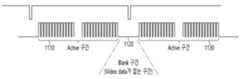
상기 프로세서는 상기 영상 프레임의 액티브 구간과 이전 영상 프레임의 액티브 구간 사이에 존재하는 블랭크 구간에 상기 APL 값을 상기 타이밍 컨트롤러에 전달할 수 있다.The above processor can transmit the APL value to the timing controller during a blank period existing between the active period of the image frame and the active period of a previous image frame.
본 개시의 실시 예에 따르면, 프레임 메모리의 제거에 따라 칩 사이즈가 감소되고, 비용이 절감되는 효과가 있다.According to an embodiment of the present disclosure, the chip size is reduced and the cost is reduced by eliminating the frame memory.
본 개시의 실시 예에 따르면, APL 값과 같은 데이터의 전송 시 추가적인 인터페이스가 필요하지 않아, 기존의 Vx1 규격을 효율적으로 이용할 수 있다.According to an embodiment of the present disclosure, no additional interface is required when transmitting data such as APL values, so that the existing Vx1 standard can be efficiently utilized.
도 1은 본 개시의 일 실시 예에 따른 디스플레이 장치를 도시한 도면이다.
도 2는 도 1의 디스플레이 장치의 구성을 블록도로 도시한 것이다.
도 3은 도 2의 제어부의 내부 블록도의 일 예이다.
도 4a는 도 2의 원격제어장치의 제어 방법을 도시한 도면이다.
도 4b는 도 2의 원격제어장치의 내부 블록도이다.
도 5는 도 2의 디스플레이부의 내부 블록도이다.
도 6a 내지 도 6b는 도 5의 유기발광패널의 설명에 참조되는 도면이다.
도 7a 내지 도 7b는 종래 기술에 따른 OLED 디스플레이 장치가 영상 데이터를 저장하는 프레임 메모리를 이용하여 영상 데이터의 APL 및 전류를 계산하는 과정을 설명하는 도면이다.
도 8은 본 개시의 일 실시 예에 따른 OLED 표시 장치의 구성을 설명하기 위한 도면이다.
도 9는 본 개시의 일 실시 예에 따른 OLED 표시 장치의 동작 방법을 설명하기 위한 흐름도이다.
도 10은 본 개시의 또 다른 실시 예에 따른 OLED 표시 장치의 동작 방법을 설명하기 위한 흐름도이다.
도 11은 본 개시의 일 실시 예에 따라 프로세서가 타이밍 컨트롤러에 Vx1 규격으로 APL 값 또는 APL 값 및 전류 값을 전달하는 과정을 설명하는 도면이다.FIG. 1 is a drawing illustrating a display device according to one embodiment of the present disclosure.
Figure 2 is a block diagram illustrating the configuration of the display device of Figure 1.
Figure 3 is an example of an internal block diagram of the control unit of Figure 2.
FIG. 4a is a drawing illustrating a control method of the remote control device of FIG. 2.
Figure 4b is an internal block diagram of the remote control device of Figure 2.
Figure 5 is an internal block diagram of the display unit of Figure 2.
FIGS. 6A and 6B are drawings for reference in the description of the organic light-emitting panel of FIG. 5.
FIGS. 7A and 7B are drawings explaining a process in which an OLED display device according to a conventional technology calculates APL and current of image data using a frame memory that stores image data.
FIG. 8 is a drawing for explaining the configuration of an OLED display device according to one embodiment of the present disclosure.
FIG. 9 is a flowchart for explaining an operating method of an OLED display device according to an embodiment of the present disclosure.
FIG. 10 is a flowchart for explaining an operating method of an OLED display device according to another embodiment of the present disclosure.
FIG. 11 is a diagram illustrating a process in which a processor transmits an APL value or an APL value and a current value in Vx1 format to a timing controller according to one embodiment of the present disclosure.
이하에서는 도면을 참조하여 본 개시를 보다 상세하게 설명한다.Hereinafter, the present disclosure will be described in more detail with reference to the drawings.
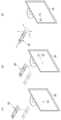
도 1은 본 개시의 일 실시 예에 따른 디스플레이 장치를 도시한 도면이다.FIG. 1 is a drawing illustrating a display device according to one embodiment of the present disclosure.
도면을 참조하면, 디스플레이 장치(100)는, 디스플레이부(180)를 포함할 수 있다.Referring to the drawing, the display device (100) may include a display unit (180).
한편, 디스플레이부(180)는 다양한 패널 중 어느 하나로 구현될 수 있다. 예를 들어, 디스플레이부(180)는, 액정표시패널(LCD 패널), 유기발광패널(OLED 패널), 무기발광패널(LED 패널) 등 중 어느 하나일 수 있다.Meanwhile, the display unit (180) may be implemented as any one of various panels. For example, the display unit (180) may be any one of a liquid crystal display panel (LCD panel), an organic light-emitting panel (OLED panel), an inorganic light-emitting panel (LED panel), etc.
본 개시에서는, 디스플레이부(180)가 유기발광패널(OLED 패널)을 구비하는 것으로 한다. 그러나, 이는 예시적인 것에 불과하며, 디스플레이부(180)는 유기발광패널(OLED 패널)이 아닌 다른 패널을 구비할 수도 있다.In this disclosure, the display unit (180) is provided with an organic light-emitting panel (OLED panel). However, this is merely exemplary, and the display unit (180) may be provided with a panel other than an organic light-emitting panel (OLED panel).
한편, 도 1의 디스플레이 장치(100)는, 모니터, TV, 태블릿 PC, 이동 단말기 등이 가능하다.Meanwhile, the display device (100) of Fig. 1 can be a monitor, TV, tablet PC, mobile terminal, etc.
도 2는 도 1의 디스플레이 장치의 구성을 블록도로 도시한 것이다.Figure 2 is a block diagram illustrating the configuration of the display device of Figure 1.
도 2를 참조하면, 디스플레이 장치(100)는 방송 수신부(130), 외부장치 인터페이스부(135), 저장부(140), 사용자입력 인터페이스부(150), 제어부(170), 무선 통신부(173), 디스플레이부(180), 오디오 출력부(185), 전원공급부(190)를 포함할 수 있다.Referring to FIG. 2, the display device (100) may include a broadcast receiving unit (130), an external device interface unit (135), a storage unit (140), a user input interface unit (150), a control unit (170), a wireless communication unit (173), a display unit (180), an audio output unit (185), and a power supply unit (190).
방송 수신부(130)는 튜너(131), 복조부(132) 및 네트워크 인터페이스부(133)를 포함할 수 있다.The broadcast receiving unit (130) may include a tuner (131), a demodulator (132), and a network interface unit (133).
튜너(131)는 채널 선국 명령에 따라 특정 방송 채널을 선국할 수 있다. 튜너(131)는 선국된 특정 방송 채널에 대한 방송 신호를 수신할 수 있다.The tuner (131) can select a specific broadcast channel according to a channel selection command. The tuner (131) can receive a broadcast signal for the selected specific broadcast channel.
복조부(132)는 수신한 방송 신호를 비디오 신호, 오디오 신호, 방송 프로그램과 관련된 데이터 신호로 분리할 수 있고, 분리된 비디오 신호, 오디오 신호 및 데이터 신호를 출력이 가능한 형태로 복원할 수 있다.The demodulator (132) can separate the received broadcast signal into a video signal, an audio signal, and a data signal related to the broadcast program, and can restore the separated video signal, audio signal, and data signal into a form that can be output.
네트워크 인터페이스부(133)는 디스플레이 장치(100)를 인터넷망을 포함하는 유/무선 네트워크와 연결하기 위한 인터페이스를 제공할 수 있다. 네트워크 인터페이스부(133)는 접속된 네트워크 또는 접속된 네트워크에 링크된 다른 네트워크를 통해, 다른 사용자 또는 다른 전자 기기와 데이터를 송신 또는 수신할 수 있다.The network interface unit (133) can provide an interface for connecting the display device (100) to a wired/wireless network including the Internet. The network interface unit (133) can transmit or receive data with other users or other electronic devices through the connected network or another network linked to the connected network.
네트워크 인터페이스부(133)는 접속된 네트워크 또는 접속된 네트워크에 링크된 다른 네트워크를 통해, 소정 웹 페이지에 접속할 수 있다. 즉, 네트워크를 통해 소정 웹 페이지에 접속하여, 해당 서버와 데이터를 송신 또는 수신할 수 있다.The network interface unit (133) can access a predetermined web page through a connected network or another network linked to the connected network. That is, it can access a predetermined web page through a network and transmit or receive data with the corresponding server.
그리고, 네트워크 인터페이스부(133)는 컨텐츠 제공자 또는 네트워크 운영자가 제공하는 컨텐츠 또는 데이터들을 수신할 수 있다. 즉, 네트워크 인터페이스부(133)는 네트워크를 통하여 컨텐츠 제공자 또는 네트워크 제공자로부터 제공되는 영화, 광고, 게임, VOD, 방송 신호 등의 컨텐츠 및 그와 관련된 정보를 수신할 수 있다.In addition, the network interface unit (133) can receive content or data provided by a content provider or a network operator. That is, the network interface unit (133) can receive content such as movies, advertisements, games, VOD, broadcast signals, etc., and information related thereto provided from a content provider or a network provider through a network.
또한, 네트워크 인터페이스부(133)는 네트워크 운영자가 제공하는 펌웨어의 업데이트 정보 및 업데이트 파일을 수신할 수 있으며, 인터넷 또는 컨텐츠 제공자 또는 네트워크 운영자에게 데이터들을 송신할 수 있다.In addition, the network interface unit (133) can receive firmware update information and update files provided by the network operator, and transmit data to the Internet or content provider or network operator.
네트워크 인터페이스부(133)는 네트워크를 통해, 공중에 공개(open)된 애플리케이션들 중 원하는 애플리케이션을 선택하여 수신할 수 있다.The network interface unit (133) can select and receive a desired application from among applications open to the public via a network.
외부장치 인터페이스부(135)는 인접하는 외부 장치 내의 애플리케이션 또는 애플리케이션 목록을 수신하여, 제어부(170) 또는 저장부(140)로 전달할 수 있다.The external device interface unit (135) can receive an application or a list of applications in an adjacent external device and transmit it to the control unit (170) or storage unit (140).
외부장치 인터페이스부(135)는 디스플레이 장치(100)와 외부 장치 간의 연결 경로를 제공할 수 있다. 외부장치 인터페이스부(135)는 디스플레이 장치(100)에 무선 또는 유선으로 연결된 외부장치로부터 출력된 영상, 오디오 중 하나 이상을 수신하여, 제어부(170)로 전달할 수 있다. 외부장치 인터페이스부(135)는 복수의 외부 입력 단자들을 포함할 수 있다. 복수의 외부 입력 단자들은 RGB 단자, 하나 이상의 HDMI(High Definition Multimedia Interface) 단자, 컴포넌트(Component) 단자를 포함할 수 있다.The external device interface unit (135) can provide a connection path between the display device (100) and the external device. The external device interface unit (135) can receive one or more of images and audio output from an external device connected wirelessly or wiredly to the display device (100) and transmit them to the control unit (170). The external device interface unit (135) can include a plurality of external input terminals. The plurality of external input terminals can include an RGB terminal, one or more HDMI (High Definition Multimedia Interface) terminals, and a component terminal.
외부장치 인터페이스부(135)를 통해 입력된 외부장치의 영상 신호는 디스플레이부(180)를 통해 출력될 수 있다. 외부장치 인터페이스부(135)를 통해 입력된 외부장치의 음성 신호는 오디오 출력부(185)를 통해 출력될 수 있다.A video signal of an external device input through the external device interface unit (135) can be output through the display unit (180). A voice signal of an external device input through the external device interface unit (135) can be output through the audio output unit (185).
외부장치 인터페이스부(135)에 연결 가능한 외부 장치는 셋톱 박스, 블루레이 플레이어, DVD 플레이어, 게임기, 사운드 바, 스마트폰, PC, USB 메모리, 홈 씨어터 중 어느 하나일 수 있으나, 이는 예시에 불과하다.An external device that can be connected to the external device interface unit (135) may be any one of a set-top box, a Blu-ray player, a DVD player, a game console, a sound bar, a smartphone, a PC, a USB memory, and a home theater, but this is only an example.
또한, 디스플레이 장치(100)에 미리 등록된 다른 사용자 또는 다른 전자 기기 중 선택된 사용자 또는 선택된 전자기기에, 디스플레이 장치(100)에 저장된 일부의 컨텐츠 데이터를 송신할 수 있다.In addition, some of the content data stored in the display device (100) can be transmitted to a selected user or electronic device among other users or other electronic devices pre-registered in the display device (100).
저장부(140)는 제어부(170) 내의 각 신호 처리 및 제어를 위한 프로그램을 저장하고, 신호 처리된 영상, 음성 또는 데이터신호를 저장할 수 있다.The storage unit (140) stores programs for each signal processing and control within the control unit (170) and can store signal-processed images, voices, or data signals.
또한, 저장부(140)는 외부장치 인터페이스부(135) 또는 네트워크 인터페이스부(133)로부터 입력되는 영상, 음성, 또는 데이터 신호의 임시 저장을 위한 기능을 수행할 수도 있으며, 채널 기억 기능을 통하여 소정 이미지에 관한 정보를 저장할 수도 있다.In addition, the storage unit (140) may perform a function for temporary storage of video, audio, or data signals input from an external device interface unit (135) or a network interface unit (133), and may also store information about a specific image through a channel memory function.
저장부(140)는 외부장치 인터페이스부(135) 또는 네트워크 인터페이스부(133)로부터 입력되는 애플리케이션 또는 애플리케이션 목록을 저장할 수 있다.The storage unit (140) can store an application or a list of applications input from an external device interface unit (135) or a network interface unit (133).
디스플레이 장치(100)는 저장부(140) 내에 저장되어 있는 컨텐츠 파일(동영상 파일, 정지영상 파일, 음악 파일, 문서 파일, 애플리케이션 파일 등)을 재생하여 사용자에게 제공할 수 있다.The display device (100) can play content files (video files, still image files, music files, document files, application files, etc.) stored in the storage unit (140) and provide them to the user.
사용자입력 인터페이스부(150)는 사용자가 입력한 신호를 제어부(170)로 전달하거나, 제어부(170)로부터의 신호를 사용자에게 전달할 수 있다. 예를 들어, 사용자입력 인터페이스부(150)는 블루투스(Bluetooth), WB(Ultra Wideband), 지그비(ZigBee) 방식, RF(Radio Frequency) 통신 방식 또는 적외선(IR) 통신 방식 등 다양한 통신 방식에 따라, 원격제어장치(200)로부터 전원 온/오프, 채널 선택, 화면 설정 등의 제어 신호를 수신하여 처리하거나, 제어부(170)로부터의 제어 신호를 원격제어장치(200)로 송신하도록 처리할 수 있다.The user input interface unit (150) can transmit a signal input by the user to the control unit (170), or transmit a signal from the control unit (170) to the user. For example, the user input interface unit (150) can receive and process control signals such as power on/off, channel selection, and screen setting from the remote control device (200) according to various communication methods such as Bluetooth, Ultra Wideband (WB), ZigBee, RF (Radio Frequency) communication, or infrared (IR) communication, or process the control signals from the control unit (170) to be transmitted to the remote control device (200).
또한, 사용자입력 인터페이스부(150)는, 전원키, 채널키, 볼륨키, 설정치 등의 로컬키(미도시)에서 입력되는 제어 신호를 제어부(170)에 전달할 수 있다.In addition, the user input interface unit (150) can transmit control signals input from local keys (not shown) such as a power key, channel key, volume key, and setting value to the control unit (170).
제어부(170)에서 영상 처리된 영상 신호는 디스플레이부(180)로 입력되어 해당 영상 신호에 대응하는 영상으로 표시될 수 있다. 또한, 제어부(170)에서 영상 처리된 영상 신호는 외부장치 인터페이스부(135)를 통하여 외부 출력장치로 입력될 수 있다.An image signal processed in the control unit (170) may be input to the display unit (180) and displayed as an image corresponding to the image signal. In addition, an image signal processed in the control unit (170) may be input to an external output device through the external device interface unit (135).
제어부(170)에서 처리된 음성 신호는 오디오 출력부(185)로 오디오 출력될 수 있다. 또한, 제어부(170)에서 처리된 음성 신호는 외부장치 인터페이스부(135)를 통하여 외부 출력장치로 입력될 수 있다.The voice signal processed in the control unit (170) can be output as audio to the audio output unit (185). In addition, the voice signal processed in the control unit (170) can be input to an external output device through the external device interface unit (135).
그 외, 제어부(170)는, 디스플레이 장치(100) 내의 전반적인 동작을 제어할 수 있다.In addition, the control unit (170) can control the overall operation within the display device (100).
또한, 제어부(170)는 사용자입력 인터페이스부(150)를 통하여 입력된 사용자 명령 또는 내부 프로그램에 의하여 디스플레이 장치(100)를 제어할 수 있으며, 네트워크에 접속하여 사용자가 원하는 애플리케이션 또는 애플리케이션 목록을 디스플레이 장치(100) 내로 다운받을 수 있도록 할 수 있다.In addition, the control unit (170) can control the display device (100) by a user command or internal program input through the user input interface unit (150), and can connect to a network to allow the user to download a desired application or application list into the display device (100).
제어부(170)는 사용자가 선택한 채널 정보 등이 처리한 영상 또는 음성신호와 함께 디스플레이부(180) 또는 오디오 출력부(185)를 통하여 출력될 수 있도록 한다.The control unit (170) enables the user-selected channel information, etc. to be output through the display unit (180) or audio output unit (185) together with the processed image or audio signal.
또한, 제어부(170)는 사용자입력 인터페이스부(150)를 통하여 수신한 외부장치 영상 재생 명령에 따라, 외부장치 인터페이스부(135)를 통하여 입력되는 외부 장치, 예를 들어, 카메라 또는 캠코더로부터의, 영상 신호 또는 음성 신호가 디스플레이부(180) 또는 오디오 출력부(185)를 통해 출력될 수 있도록 한다.In addition, the control unit (170) enables a video signal or audio signal from an external device, for example, a camera or camcorder, input through the external device interface unit (135) to be output through the display unit (180) or audio output unit (185) according to an external device video playback command received through the user input interface unit (150).
한편, 제어부(170)는 영상을 표시하도록 디스플레이부(180)를 제어할 수 있으며, 예를 들어 튜너(131)를 통해 입력되는 방송 영상, 또는 외부장치 인터페이스부(135)를 통해 입력되는 외부 입력 영상, 또는 네트워크 인터페이스부를 통해 입력되는 영상, 또는 저장부(140)에 저장된 영상이 디스플레이부(180)에서 표시되도록 제어할 수 있다. 이 경우, 디스플레이부(180)에 표시되는 영상은 정지 영상 또는 동영상일 수 있으며, 2D 영상 또는 3D 영상일 수 있다.Meanwhile, the control unit (170) can control the display unit (180) to display an image, and for example, can control the display unit (180) to display a broadcast image input through the tuner (131), an external input image input through the external device interface unit (135), an image input through the network interface unit, or an image stored in the storage unit (140). In this case, the image displayed on the display unit (180) can be a still image or a moving image, and can be a 2D image or a 3D image.
또한, 제어부(170)는 디스플레이 장치(100) 내에 저장된 컨텐츠, 또는 수신된 방송 컨텐츠, 외부로부터 입력되는 외부 입력 컨텐츠가 재생되도록 제어할 수 있으며, 상기 컨텐츠는 방송 영상, 외부 입력 영상, 오디오 파일, 정지 영상, 접속된 웹 화면, 및 문서 파일 등 다양한 형태일 수 있다.In addition, the control unit (170) can control the playback of content stored in the display device (100), received broadcast content, or external input content input from the outside, and the content can be in various forms such as broadcast images, external input images, audio files, still images, connected web screens, and document files.
무선 통신부(173)는 유선 또는 무선 통신을 통해 외부 기기와 통신을 수행할 수 있다. 무선 통신부(173)는 외부 기기와 근거리 통신(Short range communication)을 수행할 수 있다. 이를 위해, 무선 통신부(173)는 블루투스(Bluetooth™), BLE(Bluetooth Low Energy), RFID(Radio Frequency Identification), 적외선 통신(Infrared Data Association; IrDA), UWB(Ultra Wideband), ZigBee, NFC(Near Field Communication), Wi-Fi(Wireless-Fidelity), Wi-Fi Direct, Wireless USB(Wireless Universal Serial Bus) 기술 중 적어도 하나를 이용하여, 근거리 통신을 지원할 수 있다. 이러한, 무선 통신부(173)는 근거리 무선 통신망(Wireless Area Networks)을 통해 디스플레이 장치(100)와 무선 통신 시스템 사이, 디스플레이 장치(100)와 다른 디스플레이 장치(100) 사이, 또는 디스플레이 장치(100)와 디스플레이 장치(100, 또는 외부서버)가 위치한 네트워크 사이의 무선 통신을 지원할 수 있다. 근거리 무선 통신망은 근거리 무선 개인 통신망(Wireless Personal Area Networks)일 수 있다.The wireless communication unit (173) can perform communication with an external device through wired or wireless communication. The wireless communication unit (173) can perform short range communication with an external device. To this end, the wireless communication unit (173) can support short range communication by using at least one of Bluetooth™, BLE (Bluetooth Low Energy), RFID (Radio Frequency Identification), Infrared Data Association (IrDA), UWB (Ultra Wideband), ZigBee, NFC (Near Field Communication), Wi-Fi (Wireless-Fidelity), Wi-Fi Direct, and Wireless USB (Wireless Universal Serial Bus) technologies. The wireless communication unit (173) can support wireless communication between the display device (100) and a wireless communication system, between the display device (100) and another display device (100), or between the display device (100) and a network where the display device (100, or an external server) is located via a short-range wireless communication network (Wireless Area Networks). The short-range wireless communication network can be a short-range wireless personal area network (Wireless Personal Area Networks).
여기에서, 다른 디스플레이 장치(100)는 본 개시에 따른 디스플레이 장치(100)와 데이터를 상호 교환하는 것이 가능한(또는 연동 가능한) 웨어러블 디바이스(wearable device, 예를 들어, 스마트워치(smartwatch), 스마트 글래스(smart glass), HMD(head mounted display)), 스마트 폰과 같은 이동 단말기가 될 수 있다. 무선 통신부(173)는 디스플레이 장치(100) 주변에, 통신 가능한 웨어러블 디바이스를 감지(또는 인식)할 수 있다. 나아가, 제어부(170)는 감지된 웨어러블 디바이스가 본 개시에 따른 디스플레이 장치(100)와 통신하도록 인증된(authenticated) 디바이스인 경우, 디스플레이 장치(100)에서 처리되는 데이터의 적어도 일부를, 무선 통신부(173)를 통해 웨어러블 디바이스로 송신할 수 있다. 따라서, 웨어러블 디바이스의 사용자는, 디스플레이 장치(100)에서 처리되는 데이터를, 웨어러블 디바이스를 통해 이용할 수 있다.Here, the other display device (100) may be a wearable device (e.g., a smartwatch, smart glass, a head mounted display (HMD)) or a mobile terminal such as a smart phone that can exchange data with the display device (100) according to the present disclosure (or can be linked). The wireless communication unit (173) may detect (or recognize) a wearable device capable of communication around the display device (100). Furthermore, if the detected wearable device is an authenticated device to communicate with the display device (100) according to the present disclosure, the control unit (170) may transmit at least a part of the data processed in the display device (100) to the wearable device through the wireless communication unit (173). Therefore, a user of the wearable device may use the data processed in the display device (100) through the wearable device.
디스플레이부(180)는 제어부(170)에서 처리된 영상 신호, 데이터 신호, OSD 신호 또는 외부장치 인터페이스부(135)에서 수신되는 영상 신호, 데이터 신호 등을 각각 R, G, B 신호로 변환하여 구동 신호를 생성할 수 있다.The display unit (180) can generate a driving signal by converting a video signal, data signal, OSD signal processed by the control unit (170) or a video signal, data signal, etc. received from the external device interface unit (135) into R, G, B signals, respectively.
한편, 도 2에 도시된 디스플레이 장치(100)는 본 개시의 일 실시 예에 불과하므로. 도시된 구성요소들 중 일부는 실제 구현되는 디스플레이 장치(100)의 사양에 따라 통합, 추가, 또는 생략될 수 있다.Meanwhile, since the display device (100) illustrated in FIG. 2 is only an embodiment of the present disclosure, some of the illustrated components may be integrated, added, or omitted depending on the specifications of the display device (100) actually implemented.
즉, 필요에 따라 2 이상의 구성요소가 하나의 구성요소로 합쳐지거나, 혹은 하나의 구성요소가 2 이상의 구성요소로 세분되어 구성될 수 있다. 또한, 각 블록에서 수행하는 기능은 본 개시의 실시 예를 설명하기 위한 것이며, 그 구체적인 동작이나 장치는 본 개시의 권리범위를 제한하지 아니한다.That is, two or more components may be combined into one component, or one component may be subdivided into two or more components, as needed. In addition, the functions performed by each block are intended to explain embodiments of the present disclosure, and the specific operations or devices thereof do not limit the scope of the present disclosure.
본 개시의 또 다른 실시 예에 따르면, 디스플레이 장치(100)는 도 2에 도시된 바와 달리, 튜너(131)와 복조부(132)를 구비하지 않고 네트워크 인터페이스부(133) 또는 외부장치 인터페이스부(135)를 통해서 영상을 수신하여 재생할 수도 있다.According to another embodiment of the present disclosure, unlike as illustrated in FIG. 2, the display device (100) may receive and play back an image through a network interface unit (133) or an external device interface unit (135) without having a tuner (131) and a demodulator (132).
예를 들어, 디스플레이 장치(100)는 방송 신호 또는 다양한 네트워크 서비스에 따른 컨텐츠들을 수신하기 위한 등과 같은 셋톱 박스 등과 같은 영상 처리 장치와 상기 영상 처리 장치로부터 입력되는 컨텐츠를 재생하는 컨텐츠 재생 장치로 분리되어 구현될 수 있다.For example, the display device (100) may be implemented separately as an image processing device, such as a set-top box for receiving broadcast signals or contents according to various network services, and a content playback device for playing contents input from the image processing device.
이 경우, 이하에서 설명할 본 개시의 실시 예에 따른 디스플레이 장치의 동작 방법은 도 2를 참조하여 설명한 바와 같은 디스플레이 장치(100)뿐 아니라, 상기 분리된 셋톱 박스 등과 같은 영상 처리 장치 또는 디스플레이부(180) 및 오디오출력부(185)를 구비하는 컨텐츠 재생 장치 중 어느 하나에 의해 수행될 수도 있다.In this case, the operating method of the display device according to the embodiment of the present disclosure to be described below may be performed by any one of the display device (100) described with reference to FIG. 2, as well as an image processing device such as the separated set-top box, or a content playback device having a display unit (180) and an audio output unit (185).
오디오 출력부(185)는, 제어부(170)에서 음성 처리된 신호를 입력 받아 음성으로 출력한다.The audio output unit (185) receives a signal processed by the control unit (170) and outputs it as voice.
전원 공급부(190)는, 디스플레이 장치(100) 전반에 걸쳐 해당 전원을 공급한다. 특히, 시스템 온 칩(System On Chip, SOC)의 형태로 구현될 수 있는 제어부(170)와, 영상 표시를 위한 디스플레이부(180), 및 오디오 출력을 위한 오디오 출력부(185) 등에 전원을 공급할 수 있다.The power supply unit (190) supplies power to the entire display device (100). In particular, power can be supplied to a control unit (170) that can be implemented in the form of a system on chip (SOC), a display unit (180) for displaying images, and an audio output unit (185) for audio output.
구체적으로, 전원 공급부(190)는, 교류 전원을 직류 전원으로 변환하는 컨버터와, 직류 전원의 레벨을 변환하는 dc/dc 컨버터를 구비할 수 있다.Specifically, the power supply unit (190) may be equipped with a converter that converts AC power into DC power and a dc/dc converter that converts the level of the DC power.
원격제어장치(200)는, 사용자 입력을 사용자입력 인터페이스부(150)로 송신한다. 이를 위해, 원격제어장치(200)는, 블루투스(Bluetooth), RF(Radio Frequency) 통신, 적외선(IR) 통신, UWB(Ultra Wideband), 지그비(ZigBee) 방식 등을 사용할 수 있다. 또한, 원격제어장치(200)는, 사용자입력 인터페이스부(150)에서 출력한 영상, 음성 또는 데이터 신호 등을 수신하여, 이를 원격제어장치(200)에서 표시하거나 음성 출력할 수 있다.The remote control device (200) transmits user input to the user input interface unit (150). To this end, the remote control device (200) may use Bluetooth, RF (Radio Frequency) communication, IR (Infrared) communication, UWB (Ultra Wideband), ZigBee, etc. In addition, the remote control device (200) may receive images, voices, or data signals output from the user input interface unit (150) and display or output them as voices on the remote control device (200).
도 3은 도 2의 제어부의 내부 블록도의 일 예이다.Figure 3 is an example of an internal block diagram of the control unit of Figure 2.
도면을 참조하여 설명하면, 본 개시의 일실시예에 의한 제어부(170)는, 역다중화부(310), 영상 처리부(320), 프로세서(330), OSD 생성부(340), 믹서(345), 프레임 레이트 변환부(350), 및 포맷터(360)를 포함할 수 있다. 그 외 오디오 처리부(미도시), 데이터 처리부(미도시)를 더 포함할 수 있다.Referring to the drawings, a control unit (170) according to an embodiment of the present disclosure may include a demultiplexer (310), an image processing unit (320), a processor (330), an OSD generation unit (340), a mixer (345), a frame rate conversion unit (350), and a formatter (360). In addition, an audio processing unit (not shown) and a data processing unit (not shown) may be further included.
역다중화부(310)는, 입력되는 스트림을 역다중화한다. 예를 들어, MPEG-2 TS가 입력되는 경우 이를 역다중화하여, 각각 영상, 음성 및 데이터 신호로 분리할 수 있다. 여기서, 역다중화부(310)에 입력되는 스트림 신호는, 튜너(131) 또는 복조부(132) 또는 외부장치 인터페이스부(135)에서 출력되는 스트림 신호일 수 있다.The demultiplexer (310) demultiplexes the input stream. For example, if MPEG-2 TS is input, it can be demultiplexed to separate it into video, audio, and data signals, respectively. Here, the stream signal input to the demultiplexer (310) may be a stream signal output from the tuner (131), the demodulator (132), or the external device interface unit (135).
영상 처리부(320)는, 역다중화된 영상 신호의 영상 처리를 수행할 수 있다. 이를 위해, 영상 처리부(320)는, 영상 디코더(325), 및 스케일러(335)를 구비할 수 있다.The image processing unit (320) can perform image processing of a demultiplexed image signal. To this end, the image processing unit (320) can be equipped with an image decoder (325) and a scaler (335).
영상 디코더(325)는, 역다중화된 영상신호를 복호화하며, 스케일러(335)는, 복호화된 영상신호의 해상도를 디스플레이부(180)에서 출력 가능하도록 스케일링(scaling)을 수행한다.The video decoder (325) decodes the demultiplexed video signal, and the scaler (335) scales the resolution of the decoded video signal so that it can be output on the display unit (180).
영상 디코더(325)는 다양한 규격의 디코더를 구비하는 것이 가능하다. 예를 들어, MPEG-2, H,264 디코더, 색차 영상(color image) 및 깊이 영상(depth image)에 대한 3D 영상 디코더, 복수 시점 영상에 대한 디코더 등을 구비할 수 있다.The video decoder (325) can be equipped with decoders of various standards. For example, it can be equipped with an MPEG-2, H.264 decoder, a 3D video decoder for color images and depth images, a decoder for multi-view images, etc.
프로세서(330)는, 디스플레이 장치(100) 내 또는 제어부(170) 내의 전반적인 동작을 제어할 수 있다. 예를 들어, 프로세서(330)는 튜너(131)를 제어하여, 사용자가 선택한 채널 또는 기저장된 채널에 해당하는 RF 방송을 선택(Tuning)하도록 제어할 수 있다.The processor (330) can control the overall operation within the display device (100) or within the control unit (170). For example, the processor (330) can control the tuner (131) to select (tune) an RF broadcast corresponding to a channel selected by a user or a pre-stored channel.
또한, 프로세서(330)는, 사용자입력 인터페이스부(150)를 통하여 입력된 사용자 명령 또는 내부 프로그램에 의하여 디스플레이 장치(100)를 제어할 수 있다.Additionally, the processor (330) can control the display device (100) by a user command or internal program input through the user input interface unit (150).
또한, 프로세서(330)는, 네트워크 인터페이스부(135) 또는 외부장치 인터페이스부(135)와의 데이터 전송 제어를 수행할 수 있다.Additionally, the processor (330) can perform data transmission control with the network interface unit (135) or the external device interface unit (135).
또한, 프로세서(330)는, 제어부(170) 내의 역다중화부(310), 영상 처리부(320), OSD 생성부(340) 등의 동작을 제어할 수 있다.Additionally, the processor (330) can control the operation of the demultiplexing unit (310), the image processing unit (320), the OSD generation unit (340), etc. within the control unit (170).
OSD 생성부(340)는, 사용자 입력에 따라 또는 자체적으로 OSD 신호를 생성한다. 예를 들어, 사용자 입력 신호에 기초하여, 디스플레이부(180)의 화면에 각종 정보를 그래픽(Graphic)이나 텍스트(Text)로 표시하기 위한 신호를 생성할 수 있다. 생성되는 OSD 신호는, 디스플레이 장치(100)의 사용자 인터페이스 화면, 다양한 메뉴 화면, 위젯, 아이콘 등의 다양한 데이터를 포함할 수 있다. 또한, 생성되는 OSD 신호는, 2D 오브젝트 또는 3D 오브젝트를 포함할 수 있다.The OSD generation unit (340) generates an OSD signal based on a user input or on its own. For example, based on a user input signal, a signal for displaying various information as graphics or text on the screen of the display unit (180) may be generated. The generated OSD signal may include various data such as a user interface screen of the display device (100), various menu screens, widgets, and icons. In addition, the generated OSD signal may include a 2D object or a 3D object.
또한, OSD 생성부(340)는, 원격제어장치(200)로부터 입력되는 포인팅 신호에 기초하여, 디스플레이부(180)에 표시 가능한, 포인터를 생성할 수 있다. 특히, 이러한 포인터는, 포인팅 신호 처리부에서 생성될 수 있으며, OSD 생성부(340)는, 이러한 포인팅 신호 처리부(미도시)를 포함할 수 있다. 물론, 포인팅 신호 처리부(미도시)가 OSD 생성부(340) 내에 구비되지 않고 별도로 마련되는 것도 가능하다.In addition, the OSD generation unit (340) can generate a pointer that can be displayed on the display unit (180) based on a pointing signal input from the remote control device (200). In particular, such a pointer can be generated in the pointing signal processing unit, and the OSD generation unit (340) can include such a pointing signal processing unit (not shown). Of course, the pointing signal processing unit (not shown) can also be provided separately, rather than being included in the OSD generation unit (340).
믹서(345)는, OSD 생성부(340)에서 생성된 OSD 신호와 영상 처리부(320)에서 영상 처리된 복호화된 영상 신호를 믹싱할 수 있다. 믹싱된 영상 신호는 프레임 레이트 변환부(350)에 제공된다.The mixer (345) can mix the OSD signal generated by the OSD generation unit (340) and the decoded image signal processed by the image processing unit (320). The mixed image signal is provided to the frame rate conversion unit (350).
프레임 레이트 변환부(Frame Rate Conveter, FRC)(350)는, 입력되는 영상의 프레임 레이트를 변환할 수 있다. 한편, 프레임 레이트 변환부(350)는, 별도의 프레임 레이트 변환 없이, 그대로 출력하는 것도 가능하다.The frame rate converter (FRC) (350) can convert the frame rate of an input video. Meanwhile, the frame rate converter (350) can also output as is without a separate frame rate conversion.
한편, 포맷터(Formatter)(360)는, 입력되는 영상 신호의 포맷을, 디스플레이에 표시하기 위한 영상 신호로 변화시켜 출력할 수 있다.Meanwhile, the formatter (360) can change the format of an input video signal into a video signal for display on a display and output it.
포맷터(360)는, 영상 신호의 포맷을 변경할 수 있다. 예를 들어, 3D 영상 신호의 포맷을, 사이드 바이 사이드(Side by Side) 포맷, 탑 다운(Top / Down) 포맷, 프레임 시퀀셜(Frame Sequential) 포맷, 인터레이스 (Interlaced) 포맷, 체커 박스(Checker Box) 포맷 등의 다양한 3D 포맷 중 어느 하나의 포맷으로 변경할 수 있다.The formatter (360) can change the format of the video signal. For example, the format of the 3D video signal can be changed to any one of various 3D formats, such as a side-by-side format, a top-down format, a frame sequential format, an interlaced format, and a checker box format.
한편, 제어부(170) 내의 오디오 처리부(미도시)는, 역다중화된 음성 신호의 음성 처리를 수행할 수 있다. 이를 위해 오디오 처리부(미도시)는 다양한 디코더를 구비할 수 있다.Meanwhile, the audio processing unit (not shown) in the control unit (170) can perform audio processing of the demultiplexed audio signal. For this purpose, the audio processing unit (not shown) can be equipped with various decoders.
또한, 제어부(170) 내의 오디오 처리부(미도시)는, 베이스(Base), 트레블(Treble), 음량 조절 등을 처리할 수 있다.Additionally, the audio processing unit (not shown) within the control unit (170) can process bass, treble, volume control, etc.
제어부(170) 내의 데이터 처리부(미도시)는, 역다중화된 데이터 신호의 데이터 처리를 수행할 수 있다. 예를 들어, 역다중화된 데이터 신호가 부호화된 데이터 신호인 경우, 이를 복호화할 수 있다. 부호화된 데이터 신호는, 각 채널에서 방영되는 방송프로그램의 시작시간, 종료시간 등의 방송정보를 포함하는 전자 프로그램 가이드 정보(Electronic Program Guide) 정보일 수 있다.The data processing unit (not shown) in the control unit (170) can perform data processing of a demultiplexed data signal. For example, if the demultiplexed data signal is an encoded data signal, it can be decoded. The encoded data signal can be electronic program guide information including broadcast information such as the start time and end time of a broadcast program broadcast on each channel.
한편, 도 3에 도시된 제어부(170)의 블록도는 본 개시의 일 실시 예를 위한 블록도이다. 블록도의 각 구성요소는 실제 구현되는 제어부(170)의 사양에 따라 통합, 추가, 또는 생략될 수 있다.Meanwhile, the block diagram of the control unit (170) illustrated in Fig. 3 is a block diagram for one embodiment of the present disclosure. Each component of the block diagram may be integrated, added, or omitted depending on the specifications of the control unit (170) actually implemented.
특히, 프레임 레이트 변환부(350), 및 포맷터(360)는 제어부(170) 내에 마련되지 않고, 각각 별도로 구비되거나, 하나의 모듈로서 별도로 구비될 수도 있다.In particular, the frame rate converter (350) and the formatter (360) are not provided within the control unit (170), but may be provided separately, or may be provided separately as one module.
도 4a는 도 2의 원격제어장치의 제어 방법을 도시한 도면이다.FIG. 4a is a drawing illustrating a control method of the remote control device of FIG. 2.
도 4a의 (a)에 도시된 바와 같이, 디스플레이부(180)에 원격제어장치(200)에 대응하는 포인터(205)가 표시되는 것을 예시한다.As shown in (a) of Fig. 4a, a pointer (205) corresponding to a remote control device (200) is displayed on the display unit (180).
사용자는 원격제어장치(200)를 상하, 좌우(도 4a의 (b)), 앞뒤(도 4a의 (c))로 움직이거나 회전할 수 있다. 디스플레이 장치의 디스플레이부(180)에 표시된 포인터(205)는 원격제어장치(200)의 움직임에 대응한다. 이러한 원격제어장치(200)는, 도면과 같이, 3D 공간 상의 움직임에 따라 해당 포인터(205)가 이동되어 표시되므로, 공간 리모콘 또는 3D 포인팅 장치라 명명할 수 있다.The user can move or rotate the remote control device (200) up and down, left and right ((b) of FIG. 4a), forward and backward ((c) of FIG. 4a). The pointer (205) displayed on the display unit (180) of the display device corresponds to the movement of the remote control device (200). As shown in the drawing, the pointer (205) moves and is displayed according to the movement in 3D space, so the remote control device (200) can be called a space remote control or a 3D pointing device.
도 4a의 (b)는 사용자가 원격제어장치(200)를 왼쪽으로 이동하면, 디스플레이 장치의 디스플레이부(180)에 표시된 포인터(205)도 이에 대응하여 왼쪽으로 이동하는 것을 예시한다.Figure 4a (b) exemplifies that when a user moves the remote control device (200) to the left, the pointer (205) displayed on the display unit (180) of the display device also moves to the left correspondingly.
원격제어장치(200)의 센서를 통하여 감지된 원격제어장치(200)의 움직임에 관한 정보는 디스플레이 장치로 전송된다. 디스플레이 장치는 원격제어장치(200)의 움직임에 관한 정보로부터 포인터(205)의 좌표를 산출할 수 있다. 디스플레이 장치는 산출한 좌표에 대응하도록 포인터(205)를 표시할 수 있다.Information about the movement of the remote control device (200) detected through the sensor of the remote control device (200) is transmitted to the display device. The display device can calculate the coordinates of the pointer (205) from the information about the movement of the remote control device (200). The display device can display the pointer (205) corresponding to the calculated coordinates.
도 4a의 (c)는, 원격제어장치(200) 내의 특정 버튼을 누른 상태에서, 사용자가 원격제어장치(200)를 디스플레이부(180)에서 멀어지도록 이동하는 경우를 예시한다. 이에 의해, 포인터(205)에 대응하는 디스플레이부(180) 내의 선택 영역이 줌인되어 확대 표시될 수 있다. 이와 반대로, 사용자가 원격제어장치(200)를 디스플레이부(180)에 가까워지도록 이동하는 경우, 포인터(205)에 대응하는 디스플레이부(180) 내의 선택 영역이 줌아웃되어 축소 표시될 수 있다. 한편, 원격제어장치(200)가 디스플레이부(180)에서 멀어지는 경우, 선택 영역이 줌아웃되고, 원격제어장치(200)가 디스플레이부(180)에 가까워지는 경우, 선택 영역이 줌인될 수도 있다.FIG. 4A (c) illustrates a case where a user moves the remote control device (200) away from the display unit (180) while pressing a specific button within the remote control device (200). As a result, a selection area within the display unit (180) corresponding to the pointer (205) may be zoomed in and displayed in an enlarged manner. Conversely, when the user moves the remote control device (200) closer to the display unit (180), a selection area within the display unit (180) corresponding to the pointer (205) may be zoomed out and displayed in a reduced manner. Meanwhile, when the remote control device (200) moves away from the display unit (180), the selection area may be zoomed out, and when the remote control device (200) moves closer to the display unit (180), the selection area may be zoomed in.
한편, 원격제어장치(200) 내의 특정 버튼을 누른 상태에서는 상하, 좌우 이동의 인식이 배제될 수 있다. 즉, 원격제어장치(200)가 디스플레이부(180)에서 멀어지거나 접근하도록 이동하는 경우, 상,하,좌,우 이동은 인식되지 않고, 앞뒤 이동만 인식되도록 할 수 있다. 원격제어장치(200) 내의 특정 버튼을 누르지 않은 상태에서는, 원격제어장치(200)의 상,하,좌,우 이동에 따라 포인터(205)만 이동하게 된다.Meanwhile, when a specific button in the remote control device (200) is pressed, recognition of up, down, left, and right movements can be excluded. That is, when the remote control device (200) moves away from or toward the display unit (180), up, down, left, and right movements are not recognized, and only forward and backward movements can be recognized. When a specific button in the remote control device (200) is not pressed, only the pointer (205) moves according to the up, down, left, and right movements of the remote control device (200).
한편, 포인터(205)의 이동속도나 이동방향은 원격제어장치(200)의 이동속도나 이동방향에 대응할 수 있다.Meanwhile, the movement speed or movement direction of the pointer (205) can correspond to the movement speed or movement direction of the remote control device (200).
도 4b는 도 2의 원격제어장치의 내부 블록도이다.Figure 4b is an internal block diagram of the remote control device of Figure 2.
도면을 참조하여 설명하면, 원격제어장치(200)는 무선통신부(420), 사용자 입력부(430), 센서부(440), 출력부(450), 전원공급부(460), 저장부(470), 제어부(480)를 포함할 수 있다.Referring to the drawings, the remote control device (200) may include a wireless communication unit (420), a user input unit (430), a sensor unit (440), an output unit (450), a power supply unit (460), a storage unit (470), and a control unit (480).
무선통신부(420)는 전술하여 설명한 본 개시의 실시예들에 따른 디스플레이 장치 중 임의의 어느 하나와 신호를 송수신한다. 본 개시의 실시예들에 따른 디스플레이 장치들 중에서, 하나의 디스플레이 장치(100)를 일예로 설명하도록 하겠다.The wireless communication unit (420) transmits and receives signals with any one of the display devices according to the embodiments of the present disclosure described above. Among the display devices according to the embodiments of the present disclosure, one display device (100) will be described as an example.
본 실시예에서, 원격제어장치(200)는 RF 통신규격에 따라 디스플레이 장치(100)와 신호를 송수신할 수 있는 RF 모듈(421)을 구비할 수 있다. 또한 원격제어장치(200)는 IR 통신규격에 따라 디스플레이 장치(100)와 신호를 송수신할 수 있는 IR 모듈(423)을 구비할 수 있다.In this embodiment, the remote control device (200) may be equipped with an RF module (421) capable of transmitting and receiving signals with the display device (100) according to RF communication standards. In addition, the remote control device (200) may be equipped with an IR module (423) capable of transmitting and receiving signals with the display device (100) according to IR communication standards.
본 실시예에서, 원격제어장치(200)는 디스플레이 장치(100)로 원격제어장치(200)의 움직임 등에 관한 정보가 담긴 신호를 RF 모듈(421)을 통하여 전송한다.In this embodiment, the remote control device (200) transmits a signal containing information about the movement of the remote control device (200) to the display device (100) through the RF module (421).
또한, 원격제어장치(200)는 디스플레이 장치(100)가 전송한 신호를 RF 모듈(421)을 통하여 수신할 수 있다. 또한, 원격제어장치(200)는 필요에 따라 IR 모듈(423)을 통하여 디스플레이 장치(100)로 전원 온/오프, 채널 변경, 볼륨 변경 등에 관한 명령을 전송할 수 있다.In addition, the remote control device (200) can receive a signal transmitted by the display device (100) through the RF module (421). In addition, the remote control device (200) can transmit commands for power on/off, channel change, volume change, etc. to the display device (100) through the IR module (423) as needed.
사용자 입력부(430)는 키패드, 버튼, 터치 패드, 또는 터치 스크린 등으로 구성될 수 있다. 사용자는 사용자 입력부(430)를 조작하여 원격제어장치(200)로 디스플레이 장치(100)와 관련된 명령을 입력할 수 있다. 사용자 입력부(430)가 하드키 버튼을 구비할 경우 사용자는 하드키 버튼의 푸쉬 동작을 통하여 원격제어장치(200)로 디스플레이 장치(100)와 관련된 명령을 입력할 수 있다. 사용자 입력부(430)가 터치스크린을 구비할 경우 사용자는 터치스크린의 소프트키를 터치하여 원격제어장치(200)로 디스플레이 장치(100)와 관련된 명령을 입력할 수 있다. 또한, 사용자 입력부(430)는 스크롤 키나, 조그 키 등 사용자가 조작할 수 있는 다양한 종류의 입력수단을 구비할 수 있으며 본 실시예는 본 개시의 권리범위를 제한하지 아니한다.The user input unit (430) may be composed of a keypad, a button, a touch pad, or a touch screen. The user may input a command related to the display device (100) to the remote control device (200) by operating the user input unit (430). If the user input unit (430) has a hard key button, the user may input a command related to the display device (100) to the remote control device (200) by a push operation of the hard key button. If the user input unit (430) has a touch screen, the user may touch a soft key of the touch screen to input a command related to the display device (100) to the remote control device (200). In addition, the user input unit (430) may be provided with various types of input means that the user may operate, such as a scroll key or a jog key, and the present embodiment does not limit the scope of the rights of the present disclosure.
센서부(440)는 자이로 센서(441) 또는 가속도 센서(443)를 구비할 수 있다. 자이로 센서(441)는 원격제어장치(200)의 움직임에 관한 정보를 센싱할 수 있다.The sensor unit (440) may be equipped with a gyro sensor (441) or an acceleration sensor (443). The gyro sensor (441) may sense information about the movement of the remote control device (200).
일예로, 자이로 센서(441)는 원격제어장치(200)의 동작에 관한 정보를 x,y,z 축을 기준으로 센싱할 수 있다. 가속도 센서(443)는 원격제어장치(200)의 이동속도 등에 관한 정보를 센싱할 수 있다. 한편, 거리측정센서를 더 구비할 수 있으며, 이에 의해, 디스플레이부(180)와의 거리를 센싱할 수 있다.For example, the gyro sensor (441) can sense information about the operation of the remote control device (200) based on the x, y, and z axes. The acceleration sensor (443) can sense information about the moving speed of the remote control device (200). Meanwhile, a distance measuring sensor can be additionally provided, and thereby the distance to the display unit (180) can be sensed.
출력부(450)는 사용자 입력부(430)의 조작에 대응하거나 디스플레이 장치(100)에서 전송한 신호에 대응하는 영상 또는 음성 신호를 출력할 수 있다. 출력부(450)를 통하여 사용자는 사용자 입력부(430)의 조작 여부 또는 디스플레이 장치(100)의 제어 여부를 인지할 수 있다.The output unit (450) can output a video or audio signal corresponding to the operation of the user input unit (430) or to a signal transmitted from the display device (100). Through the output unit (450), the user can recognize whether the user input unit (430) is being operated or whether the display device (100) is being controlled.
일예로, 출력부(450)는 사용자 입력부(430)가 조작되거나 무선통신부(420)을 통하여 디스플레이 장치(100)와 신호가 송수신되면 점등되는 LED 모듈(451), 진동을 발생하는 진동 모듈(453), 음향을 출력하는 음향 출력 모듈(455), 또는 영상을 출력하는 디스플레이 모듈(457)을 구비할 수 있다.For example, the output unit (450) may be equipped with an LED module (451) that lights up when the user input unit (430) is operated or a signal is transmitted and received with the display device (100) through the wireless communication unit (420), a vibration module (453) that generates vibration, an audio output module (455) that outputs audio, or a display module (457) that outputs an image.
전원공급부(460)는 원격제어장치(200)로 전원을 공급한다. 전원공급부(460)는 원격제어장치(200)이 소정 시간 동안 움직이지 않은 경우 전원 공급을 중단함으로서 전원 낭비를 줄일 수 있다. 전원공급부(460)는 원격제어장치(200)에 구비된 소정 키가 조작된 경우에 전원 공급을 재개할 수 있다.The power supply unit (460) supplies power to the remote control device (200). The power supply unit (460) can reduce power waste by stopping the power supply when the remote control device (200) does not move for a predetermined period of time. The power supply unit (460) can resume the power supply when a predetermined key provided in the remote control device (200) is operated.
저장부(470)는 원격제어장치(200)의 제어 또는 동작에 필요한 여러 종류의 프로그램, 애플리케이션 데이터 등이 저장될 수 있다. 만일 원격제어장치(200)가 디스플레이 장치(100)와 RF 모듈(421)을 통하여 무선으로 신호를 송수신할 경우 원격제어장치(200)와 디스플레이 장치(100)는 소정 주파수 대역을 통하여 신호를 송수신한다. 원격제어장치(200)의 제어부(480)는 원격제어장치(200)와 페어링된 디스플레이 장치(100)와 신호를 무선으로 송수신할 수 있는 주파수 대역 등에 관한 정보를 저장부(470)에 저장하고 참조할 수 있다.The storage unit (470) can store various types of programs, application data, etc. required for the control or operation of the remote control device (200). If the remote control device (200) wirelessly transmits and receives signals through the display device (100) and the RF module (421), the remote control device (200) and the display device (100) transmit and receive signals through a predetermined frequency band. The control unit (480) of the remote control device (200) can store and refer to information about the frequency band, etc., that can wirelessly transmit and receive signals with the display device (100) paired with the remote control device (200).
제어부(480)는 원격제어장치(200)의 제어에 관련된 제반사항을 제어한다. 제어부(480)는 사용자 입력부(430)의 소정 키 조작에 대응하는 신호 또는 센서부(440)에서 센싱한 원격제어장치(200)의 움직임에 대응하는 신호를 무선통신부(420)를 통하여 디스플레이 장치(100)로 전송할 수 있다.The control unit (480) controls all matters related to the control of the remote control device (200). The control unit (480) can transmit a signal corresponding to a predetermined key operation of the user input unit (430) or a signal corresponding to the movement of the remote control device (200) sensed by the sensor unit (440) to the display device (100) through the wireless communication unit (420).
디스플레이 장치(100)의 사용자 입력 인터페이스부(150)는, 원격제어장치(200)와 무선으로 신호를 송수신할 수 있는 무선통신부(411)와, 원격제어장치(200)의 동작에 대응하는 포인터의 좌표값을 산출할 수 있는 좌표값 산출부(415)를 구비할 수 있다.The user input interface unit (150) of the display device (100) may be equipped with a wireless communication unit (411) capable of wirelessly transmitting and receiving signals with a remote control device (200), and a coordinate value calculation unit (415) capable of calculating the coordinate values of a pointer corresponding to the operation of the remote control device (200).
사용자 입력 인터페이스부(150)는, RF 모듈(412)을 통하여 원격제어장치(200)와 무선으로 신호를 송수신할 수 있다. 또한 IR 모듈(413)을 통하여 원격제어장치(200)이 IR 통신 규격에 따라 전송한 신호를 수신할 수 있다.The user input interface unit (150) can wirelessly transmit and receive signals with the remote control device (200) through the RF module (412). In addition, it can receive signals transmitted by the remote control device (200) according to the IR communication standard through the IR module (413).
좌표값 산출부(415)는 무선통신부(411)를 통하여 수신된 원격제어장치(200)의 동작에 대응하는 신호로부터 손떨림이나 오차를 수정하여 디스플레이부(180)에 표시할 포인터(205)의 좌표값(x,y)을 산출할 수 있다.The coordinate value calculation unit (415) can calculate the coordinate value (x, y) of the pointer (205) to be displayed on the display unit (180) by correcting hand shake or error from a signal corresponding to the operation of the remote control device (200) received through the wireless communication unit (411).
사용자 입력 인터페이스부(150)를 통하여 디스플레이 장치(100)로 입력된 원격제어장치(200) 전송 신호는 디스플레이 장치(100)의 제어부(170)로 전송된다. 제어부(170)는 원격제어장치(200)에서 전송한 신호로부터 원격제어장치(200)의 동작 및 키 조작에 관한 정보를 판별하고, 그에 대응하여 디스플레이 장치(100)를 제어할 수 있다.A transmission signal of a remote control device (200) input to a display device (100) through a user input interface unit (150) is transmitted to a control unit (170) of the display device (100). The control unit (170) can determine information about the operation and key operation of the remote control device (200) from the signal transmitted from the remote control device (200) and control the display device (100) in response thereto.
또 다른 예로, 원격제어장치(200)는, 그 동작에 대응하는 포인터 좌표값을 산출하여 디스플레이 장치(100)의 사용자 입력 인터페이스부(150)로 출력할 수 있다. 이 경우, 디스플레이 장치(100)의 사용자 입력 인터페이스부(150)는 별도의 손떨림이나 오차 보정 과정 없이 수신된 포인터 좌표값에 관한 정보를 제어부(170)로 전송할 수 있다.As another example, the remote control device (200) can calculate the pointer coordinate values corresponding to the operation and output them to the user input interface unit (150) of the display device (100). In this case, the user input interface unit (150) of the display device (100) can transmit information about the received pointer coordinate values to the control unit (170) without a separate hand shake or error correction process.
또한, 다른 예로, 좌표값 산출부(415)가, 도면과 달리 사용자 입력 인터페이스부(150)가 아닌, 제어부(170) 내부에 구비되는 것도 가능하다.In addition, as another example, the coordinate value calculation unit (415) may be provided within the control unit (170) rather than the user input interface unit (150), unlike in the drawing.
도 5는 도 2의 디스플레이부의 내부 블록도이다.Figure 5 is an internal block diagram of the display unit of Figure 2.
도면을 참조하면, 유기발광패널 기반의 디스플레이부(180)는, 패널(210), 제1 인터페이스부(230), 제2 인터페이스부(231), 타이밍 컨트롤러(232), 게이트 구동부(234), 데이터 구동부(236), 메모리(240), 프로세서(270), 전원 공급부(290) 등을 포함할 수 있다.Referring to the drawing, the display unit (180) based on an organic light-emitting panel may include a panel (210), a first interface unit (230), a second interface unit (231), a timing controller (232), a gate driver (234), a data driver (236), a memory (240), a processor (270), a power supply unit (290), etc.
디스플레이부(180)는, 영상 신호(Vd)와, 제1 직류 전원(V1) 및 제2 직류 전원(V2)을 수신하고, 영상 신호(Vd)에 기초하여, 소정 영상을 표시할 수 있다.The display unit (180) receives a video signal (Vd), a first DC power source (V1) and a second DC power source (V2), and can display a predetermined video based on the video signal (Vd).
한편, 디스플레이부(180) 내의 제1 인터페이스부(230)는, 제어부(170)로부터 영상 신호(Vd)와, 제1 직류 전원(V1)을 수신할 수 있다.Meanwhile, the first interface unit (230) within the display unit (180) can receive a video signal (Vd) and a first DC power source (V1) from the control unit (170).
여기서, 제1 직류 전원(V1)은, 디스플레이부(180) 내의 전원 공급부(290), 및 타이밍 컨트롤러(232)의 동작을 위해 사용될 수 있다.Here, the first DC power supply (V1) can be used for the operation of the power supply unit (290) in the display unit (180) and the timing controller (232).
다음, 제2 인터페이스부(231)는, 외부의 전원 공급부(190)로부터 제2 직류 전원(V2)을 수신할 수 있다. 한편, 제2 직류 전원(V2)은, 디스플레이부(180) 내의 데이터 구동부(236)에 입력될 수 있다.Next, the second interface unit (231) can receive a second DC power supply (V2) from an external power supply unit (190). Meanwhile, the second DC power supply (V2) can be input to a data driving unit (236) in the display unit (180).
타이밍 컨트롤러(232)는, 영상 신호(Vd)에 기초하여, 데이터 구동 신호(Sda) 및 게이트 구동 신호(Sga)를 출력할 수 있다.The timing controller (232) can output a data driving signal (Sda) and a gate driving signal (Sga) based on the image signal (Vd).
예를 들어, 제1 인터페이스부(230)가 입력되는 영상 신호(Vd)를 변환하여 변환된 영상 신호(va1)를 출력하는 경우, 타이밍 컨트롤러(232)는, 변환된 영상 신호(va1)에 기초하여, 데이터 구동 신호(Sda) 및 게이트 구동 신호(Sga)를 출력할 수 있다.For example, when the first interface unit (230) converts an input image signal (Vd) and outputs a converted image signal (va1), the timing controller (232) can output a data driving signal (Sda) and a gate driving signal (Sga) based on the converted image signal (va1).
타이밍 컨트롤러(timing controller)(232)는, 제어부(170)로부터의 비디오 신호(Vd) 외에, 제어 신호, 수직동기신호(Vsync) 등을 더 수신할 수 있다.The timing controller (232) can receive, in addition to the video signal (Vd) from the control unit (170), a control signal, a vertical synchronization signal (Vsync), etc.
그리고, 타이밍 컨트롤러(timing controller)(232)는, 비디오 신호(Vd) 외에, 제어 신호, 수직동기신호(Vsync) 등에 기초하여, 게이트 구동부(234)의 동작을 위한 게이트 구동 신호(Sga), 데이터 구동부(236)의 동작을 위한 데이터 구동 신호(Sda)를 출력할 수 있다.In addition, the timing controller (232) can output a gate drive signal (Sga) for operation of the gate drive unit (234) and a data drive signal (Sda) for operation of the data drive unit (236) based on a control signal, a vertical synchronization signal (Vsync), etc., in addition to a video signal (Vd).
이때의 데이터 구동 신호(Sda)는, 패널(210)이 RGBW의 서브픽셀을 구비하는 경우, RGBW 서브픽셀 구동용 데이터 구동 신호일 수 있다.The data driving signal (Sda) at this time may be a data driving signal for driving RGBW subpixels when the panel (210) has RGBW subpixels.
한편, 타이밍 컨트롤러(232)는, 게이트 구동부(234)에 제어 신호(Cs)를 더 출력할 수 있다.Meanwhile, the timing controller (232) can further output a control signal (Cs) to the gate driver (234).
게이트 구동부(234)와 데이터 구동부(236)는, 타이밍 컨트롤러(232)로부터의 게이트 구동 신호(Sga), 데이터 구동 신호(Sda)에 따라, 각각 게이트 라인(GL) 및 데이터 라인(DL)을 통해, 주사 신호 및 영상 신호를 패널(210)에 공급한다. 이에 따라, 패널(210)은 소정 영상을 표시하게 된다.The gate driving unit (234) and the data driving unit (236) supply a scan signal and an image signal to the panel (210) through the gate line (GL) and the data line (DL), respectively, in accordance with the gate driving signal (Sga) and the data driving signal (Sda) from the timing controller (232). Accordingly, the panel (210) displays a predetermined image.
한편, 패널(210)은, 유기 발광층을 포함할 수 있으며, 영상을 표시하기 위해, 유기 발광층에 대응하는 각 화소에, 다수개의 게이트 라인(GL) 및 데이터 라인(DL)이 매트릭스 형태로 교차하여 배치될 수 있다.Meanwhile, the panel (210) may include an organic light-emitting layer, and in order to display an image, a plurality of gate lines (GL) and data lines (DL) may be arranged in a matrix form to cross each pixel corresponding to the organic light-emitting layer.
한편, 데이터 구동부(236)는, 제2 인터페이스부(231)로부터의 제2 직류 전원(V2)에 기초하여, 패널(210)에 데이터 신호를 출력할 수 있다.Meanwhile, the data driving unit (236) can output a data signal to the panel (210) based on the second direct current power supply (V2) from the second interface unit (231).
전원 공급부(290)는, 각종 전원을, 게이트 구동부(234)와 데이터 구동부(236), 타이밍 컨트롤러(232) 등에 공급할 수 있다.The power supply unit (290) can supply various power sources to the gate driver unit (234), the data driver unit (236), the timing controller (232), etc.
프로세서(270)는, 디스플레이부(180) 내의 각종 제어를 수행할 수 있다. 예를 들어, 게이트 구동부(234)와 데이터 구동부(236), 타이밍 컨트롤러(232) 등을 제어할 수 있다.The processor (270) can perform various controls within the display unit (180). For example, it can control the gate driving unit (234), the data driving unit (236), the timing controller (232), etc.
도 6a 내지 도 6b는 도 5의 유기발광패널의 설명에 참조되는 도면이다.FIGS. 6A and 6B are drawings for reference in the description of the organic light-emitting panel of FIG. 5.
먼저, 도 6a는, 패널(210) 내의 픽셀(Pixel)을 도시하는 도면이다. 패널(210)은 유기발광패널일 수 있다.First, Fig. 6a is a drawing showing pixels within a panel (210). The panel (210) may be an organic light-emitting panel.
도면을 참조하면, 패널(210)은, 복수의 스캔 라인(Scan 1 ~ Scan n)과, 이에 교차하는 복수의 데이터 라인(R1, G1, B1, W1 ~ Rm, Gm, Bm, Wm)을 구비할 수 있다.Referring to the drawing, the panel (210) may have a plurality of scan lines (
한편, 패널(210) 내의 스캔 라인과, 데이터 라인의 교차 영역에, 픽셀(pixel)이 정의된다. 도면에서는, RGBW의 서브픽셀(SPr1, SPg1, SPb1, SPw1)을 구비하는 픽셀(Pixel)을 도시한다.Meanwhile, a pixel is defined in the intersection area of a scan line and a data line within the panel (210). In the drawing, a pixel having RGBW subpixels (SPr1, SPg1, SPb1, SPw1) is illustrated.
도 6a에서는, 하나의 픽셀에 RGBW의 서브픽셀이 구비된 것으로 도시되어 있으나, 하나의 픽셀에 RGB의 서브픽셀이 구비될 수도 있다. 즉, 픽셀의 소자 배열 방식에는 제한되지 않는다.In Fig. 6a, one pixel is illustrated as having RGBW sub-pixels, but one pixel may also have RGB sub-pixels. In other words, there is no limitation on the arrangement of pixel elements.
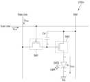
도 6b은, 도 6a의 유기발광패널의 픽셀(Pixel) 내의 어느 하나의 서브픽셀(sub pixel)의 회로를 예시한다.FIG. 6b illustrates a circuit of one sub-pixel within a pixel of the organic light-emitting panel of FIG. 6a.
도면을 참조하면, 유기발광 서브픽셀(sub pixel) 회로(CRTm)는, 능동형으로서, 스캔 스위칭 소자(SW1), 저장 커패시터(Cst), 구동 스위칭 소자(SW2), 유기발광층(OLED)을 구비할 수 있다.Referring to the drawing, the organic light-emitting sub-pixel circuit (CRTm) may be an active type and include a scan switching element (SW1), a storage capacitor (Cst), a driving switching element (SW2), and an organic light-emitting layer (OLED).
스캔 스위칭 소자(SW1)는, 게이트 단자에 스캔 라인(Scan Line)이 접속되어, 입력되는 스캔 신호(Vscan)에 따라 턴 온하게 된다. 턴 온되는 경우, 입력되는 데이터 신호(Vdata)를 구동 스위칭 소자(SW2)의 게이트 단자 또는 저장 커패시터(Cst)의 일단으로 전달하게 된다.The scan switching element (SW1) is turned on according to the input scan signal (Vscan) by connecting a scan line to the gate terminal. When turned on, the input data signal (Vdata) is transmitted to the gate terminal of the driving switching element (SW2) or one end of the storage capacitor (Cst).
저장 커패시터(Cst)는, 구동 스위칭 소자(SW2)의 게이트 단자와 소스 단자 사이에 형성되며, 저장 커패시터(Cst)의 일단에 전달되는 데이터 신호 레벨과, 저장 커패시터(Cst)의 타단에 전달되는 직류 전원(Vdd) 레벨의 소정 차이를 저장한다.The storage capacitor (Cst) is formed between the gate terminal and the source terminal of the driving switching element (SW2), and stores a predetermined difference between the data signal level transmitted to one end of the storage capacitor (Cst) and the DC power supply (Vdd) level transmitted to the other end of the storage capacitor (Cst).
예를 들어, 데이터 신호가, PAM(Pluse Amplitude Modulation) 방식에 따라 서로 다른 레벨을 갖는 경우, 데이터 신호(Vdata)의 레벨 차이에 따라, 저장 커패시터(Cst)에 저장되는 전원 레벨이 달라지게 된다.For example, if the data signal has different levels according to the PAM (Plus Amplitude Modulation) method, the power level stored in the storage capacitor (Cst) changes depending on the level difference of the data signal (Vdata).
다른 예로, 데이터 신호가 PWM(Pluse Width Modulation) 방식에 따라 서로 다른 펄스폭을 갖는 경우, 데이터 신호(Vdata)의 펄스폭 차이에 따라, 저장 커패시터(Cst)에 저장되는 전원 레벨이 달라지게 된다.As another example, when the data signal has different pulse widths according to the PWM (Pulse Width Modulation) method, the power level stored in the storage capacitor (Cst) changes depending on the difference in the pulse width of the data signal (Vdata).
구동 스위칭 소자(SW2)는, 저장 커패시터(Cst)에 저장된 전원 레벨에 따라 턴 온된다. 구동 스위칭 소자(SW2)가 턴 온하는 경우, 저장된 전원 레벨에 비례하는, 구동 전류(IOLED)가 유기발광층(OLED)에 흐르게 된다. 이에 따라, 유기발광층(OLED)은 발광동작을 수행하게 된다.The driving switching element (SW2) is turned on according to the power level stored in the storage capacitor (Cst). When the driving switching element (SW2) is turned on, a driving current (IOLED) proportional to the stored power level flows to the organic light-emitting layer (OLED). Accordingly, the organic light-emitting layer (OLED) performs a light-emitting operation.
유기발광층(OLED)은, 서브픽셀에 대응하는 RGBW의 발광층(EML)을 포함하며, 정공주입층(HIL), 정공 수송층(HTL), 전자 수송층(ETL), 전자 주입층(EIL) 중 적어도 하나를 포함할 수 있으며, 그 외에 정공 저지층 등도 포함할 수 있다.The organic light-emitting layer (OLED) includes an RGBW emission layer (EML) corresponding to the sub-pixel, and may include at least one of a hole injection layer (HIL), a hole transport layer (HTL), an electron transport layer (ETL), and an electron injection layer (EIL), and may also include a hole blocking layer.
한편, 서브픽셀(sub pixel)은, 유기발광층(OLED)에서 모두 백색의 광을 출력하나, 녹색, 적색, 청색 서브픽셀의 경우, 색상 구현을 위해, 별도의 컬러필터가 구비된다. 즉, 녹색, 적색, 청색 서브픽셀의 경우, 각각 녹색, 적색, 청색 컬러필터를 더 구비한다. 한편, 백색 서브픽셀의 경우, 백색광을 출력하므로, 별도의 컬러필터가 필요 없게 된다.Meanwhile, sub-pixels all output white light from the organic light-emitting layer (OLED), but green, red, and blue sub-pixels are provided with separate color filters for color implementation. That is, green, red, and blue sub-pixels each additionally have green, red, and blue color filters. Meanwhile, white sub-pixels output white light, so they do not require separate color filters.
한편, 도면에서는, 스캔 스위칭 소자(SW1)와 구동 스위칭 소자(SW2)로서, p타입의 MOSFET인 경우를 예시하나, n타입의 MOSFET이거나, 그 외, JFET, IGBT, 또는 SIC 등의 스위칭 소자가 사용되는 것도 가능하다.Meanwhile, in the drawing, a case is exemplified where a p-type MOSFET is used as the scan switching element (SW1) and the driving switching element (SW2), but an n-type MOSFET, or other switching elements such as a JFET, IGBT, or SIC may also be used.
도 7a 내지 도 7b는 종래 기술에 따른 OLED 디스플레이 장치가 영상 데이터를 저장하는 프레임 메모리를 이용하여 영상 데이터의 APL 및 전류를 계산하는 과정을 설명하는 도면이다.FIGS. 7A and 7B are drawings explaining a process in which an OLED display device according to a conventional technology calculates APL and current of image data using a frame memory that stores image data.
도 7a를 참조하면, 종래 기술에 따른 OLED 디스플레이 장치(700)는 메인 Soc(System On Chip, 710), 메모리(720), 제1 타이밍 컨트롤러(730-1), 제2 타이밍 컨트롤러(730-2), 제1 프레임 메모리(740-1), 제1 보상 처리 메모리(750-1), 제2 프레임 메모리(740-2) 및 제2 보상 처리 메모리(750-2)를 포함할 수 있다.Referring to FIG. 7a, an OLED display device (700) according to the prior art may include a main SoC (System On Chip, 710), a memory (720), a first timing controller (730-1), a second timing controller (730-2), a first frame memory (740-1), a first compensation processing memory (750-1), a second frame memory (740-2), and a second compensation processing memory (750-2).
메인 SoC(System on Chip, 710)는 입력된 영상의 프레임 레이트를 제어할 수 있다.The main SoC (System on Chip, 710) can control the frame rate of the input video.
메인 SoC(710)는 디스플레이 패널(미도시)의 출력 주파수에 맞게 입력된 영상의 프레임 레이트를 제어할 수 있다.The main SoC (710) can control the frame rate of the input image to match the output frequency of the display panel (not shown).
메모리(720)는 하나의 영상 프레임에 대한 영상 데이터를 저장하고 있을 수 있다. 영상 데이터는 RGB 데이터 또는 WRGB 데이터 중 어느 하나일 수 있다.The memory (720) may store image data for one image frame. The image data may be either RGB data or WRGB data.
메인 SoC(710)는 Vx1 규격을 통해 제1 타이밍 컨트롤러(730-1) 및 제2 타이밍 컨트롤러(730-2)과 통신을 수행할 수 있다.The main SoC (710) can communicate with the first timing controller (730-1) and the second timing controller (730-2) through the Vx1 standard.
메인 SoC(710)는 Vx1 규격을 통해 제1 타이밍 컨트롤러(730-1) 및 제2 타이밍 컨트롤러(730-2) 각각에 영상 데이터를 전달할 수 있다.The main SoC (710) can transmit image data to each of the first timing controller (730-1) and the second timing controller (730-2) through the Vx1 standard.
제1 타이밍 컨트롤러(730-1) 및 제2 타이밍 컨트롤러(730-2) 각각은 메인 SoC(710)로부터 수신된 영상 데이터에 기반하여 영상 프레임의 APL 값을 계산할 수 있다.Each of the first timing controller (730-1) and the second timing controller (730-2) can calculate the APL value of an image frame based on image data received from the main SoC (710).
제1 타이밍 컨트롤러(730-1) 및 제2 타이밍 컨트롤러(730-2) 각각은 PLC(Peak Luminance Control, 피크 휘도 제어) 커브를 통해 계산된 APL 값에 상응하는 디스플레이 패널의 휘도를 결정할 수 있다.Each of the first timing controller (730-1) and the second timing controller (730-2) can determine the luminance of the display panel corresponding to the APL value calculated through the PLC (Peak Luminance Control) curve.
제1 타이밍 컨트롤러(730-1) 및 제2 타이밍 컨트롤러(730-2) 각각은 결정된 휘도에 맞는 디스플레이 패널에 공급될 전류 값을 결정할 수 있다.Each of the first timing controller (730-1) and the second timing controller (730-2) can determine a current value to be supplied to the display panel according to the determined brightness.
제1 프레임 메모리(740-1) 및 제2 프레임 메모리(740-2) 각각은 하나의 영상 프레임에 대한 영상 데이터를 저장하고 있을 수 있다.Each of the first frame memory (740-1) and the second frame memory (740-2) may store image data for one image frame.
즉, 제1 타이밍 컨트롤러(730-1) 및 제2 타이밍 컨트롤러(730-2) 각각이 APL 값, 휘도, 전류 값을 계산하기 위해 제1 프레임 메모리(740-1) 및 제2 프레임 메모리(740-2) 각각은 하나의 영상 프레임에 대한 영상 데이터를 저장하고 있을 수 있다.That is, each of the first timing controller (730-1) and the second timing controller (730-2) may store image data for one image frame, while each of the first frame memory (740-1) and the second frame memory (740-2) may store image data for one image frame to calculate the APL value, brightness, and current value, respectively.
그러나, 이러한 제1 프레임 메모리(740-1) 및 제2 프레임 메모리(740-2)는 디스플레이 패널의 해상도가 커짐에 따라 영상 데이터의 처리 속도 및 용량이 증가되어 하나의 칩으로 구현이 어렵고, 하드웨어 구성을 복잡하게 만든다.However, as the resolution of the display panel increases, the processing speed and capacity of image data increase, making it difficult to implement the first frame memory (740-1) and the second frame memory (740-2) in a single chip, and making the hardware configuration complex.
제1 보상 처리 메모리(750-1)는 제1 타이밍 컨트롤러(730-1)에 전달할 복수의 픽셀들 각각의 보상량을 저장할 수 있다. 각 픽셀의 보상량은 픽셀의 열화량에 기초하여 산정될 수 있다.The first compensation processing memory (750-1) can store the compensation amount of each of a plurality of pixels to be transmitted to the first timing controller (730-1). The compensation amount of each pixel can be calculated based on the deterioration amount of the pixel.
제2 보상 처리 메모리(750-2)는 제2 타이밍 컨트롤러(730-2)에 전달할 복수의 픽셀들 각각의 보상량을 저장할 수 있다. 각 픽셀의 보상량은 픽셀의 열화량에 기초하여 산정될 수 있다.The second compensation processing memory (750-2) can store the compensation amount of each of the plurality of pixels to be transmitted to the second timing controller (730-2). The compensation amount of each pixel can be calculated based on the deterioration amount of the pixel.
도 7b는 종래 기술에 따른 타이밍 컨트롤러의 동작을 설명하는 도면이다.Fig. 7b is a drawing explaining the operation of a timing controller according to the prior art.
타이밍 컨트롤러(730)는 APL/전류 계산부(731) 및 출력 레벨 조정부(733)를 포함한다.The timing controller (730) includes an APL/current calculation unit (731) and an output level adjustment unit (733).
APL/전류 계산부(731)는 프레임 메모리(740)에 저장된 영상 데이터를 이용하여 영상 프레임의 APL 값, 디스플레이 패널의 휘도 값 및 디스플레이 패널에 공급할 전류 값을 계산한다.The APL/current calculation unit (731) calculates the APL value of an image frame, the brightness value of the display panel, and the current value to be supplied to the display panel using the image data stored in the frame memory (740).
출력 레벨 조정부(733)는 디스플레이 패널의 휘도 값에 상응하는 영상 프레임의 출력 레벨을 결정하고, 결정된 출력 레벨에 보상 처리 메모리(750)에 저장된 픽셀의 보상 레벨을 반영하여 최종 영상 데이터를 생성한다.The output level adjustment unit (733) determines the output level of the image frame corresponding to the brightness value of the display panel, and reflects the compensation level of the pixel stored in the compensation processing memory (750) to the determined output level to generate final image data.
보상 처리 메모리(750)는 각 픽셀의 열화 정도를 나타내는 열화량에 상응하는 보상 레벨을 저장하고 있다.The compensation processing memory (750) stores a compensation level corresponding to the deterioration amount indicating the degree of deterioration of each pixel.
출력 레벨 조정부(733)는 결정된 출력 레벨에 보상 레벨을 감산 또는 가산하여 출력될 영상 프레임의 최종 출력 레벨을 결정할 수 있다.The output level adjustment unit (733) can determine the final output level of the image frame to be output by subtracting or adding a compensation level to the determined output level.
최종 출력 레벨은 RGB 데이터 또는 WRGB 데이터로 표현될 수 있다.The final output level can be expressed as RGB data or WRGB data.
이와 같이, 종래 기술에 따르면, 영상 프레임의 APL 값 및 디스플레이 패널에 제공될 전류 값을 계산하기 위해 프레임 메모리(740)가 필요하다.In this way, according to the prior art, a frame memory (740) is required to calculate the APL value of the image frame and the current value to be provided to the display panel.
그러나, 프레임 메모리(740)의 존재로 인해 칩 사이즈가 커지는 문제가 있고, 하드웨어 구성이 복잡해지는 문제가 있다.However, there is a problem that the chip size increases due to the existence of frame memory (740) and the hardware configuration becomes complicated.
본 개시의 실시 예에서는 프레임 메모리(740)의 구성 없이도 영상 프레임의 APL 및 디스플레이 패널에 공급할 전류를 계산하고자 한다.In an embodiment of the present disclosure, it is intended to calculate the APL of an image frame and the current to be supplied to the display panel without configuring a frame memory (740).
도 8은 본 개시의 일 실시 예에 따른 OLED 표시 장치의 구성을 설명하기 위한 도면이다.FIG. 8 is a drawing for explaining the configuration of an OLED display device according to one embodiment of the present disclosure.
도 8을 참조하면, OLED 표시 장치(100)는 프로세서(270), 메모리(240), 타이밍 컨트롤러(232), 보상 처리 메모리(810) 및 디스플레이 패널(210)을 포함할 수 있다.Referring to FIG. 8, the OLED display device (100) may include a processor (270), a memory (240), a timing controller (232), a compensation processing memory (810), and a display panel (210).
프로세서(270)는 영상 프레임의 영상 데이터를 메모리(240)로부터 획득할 수 있다.The processor (270) can obtain image data of an image frame from the memory (240).
프로세서(270)는 획득된 영상 데이터에 기초하여 영상 프레임의 APL 값을 계산할 수 있다.The processor (270) can calculate the APL value of the image frame based on the acquired image data.
프로세서(270)는 영상 데이터 및 계산된 APL 값을 타이밍 컨트롤러(232)에 전달할 수 있다.The processor (270) can transmit image data and calculated APL values to the timing controller (232).
프로세서(270)는 Vx1 규격을 통해 영상 데이터 및 APL 값을 타이밍 컨트롤러(232)에 전달할 수 있다.The processor (270) can transmit image data and APL values to the timing controller (232) through the Vx1 standard.
메모리(240)는 하나의 영상 프레임에 대한 영상 데이터를 저장하고 있을 수 있다.The memory (240) may store image data for one image frame.
프로세서(270)는 영상 프레임의 APL 값에 기초하여 디스플레이 패널(210)의 휘도 및 디스플레이 패널(210)에 제공할 전류 값을 결정할 수 있다.The processor (270) can determine the brightness of the display panel (210) and the current value to be provided to the display panel (210) based on the APL value of the image frame.
프로세서(270)는 계산된 APL 값 및 전류 값을 타이밍 컨트롤러(232)에 전달할 수 있다.The processor (270) can transmit the calculated APL value and current value to the timing controller (232).
타이밍 컨트롤러(232)는 프로세서(270)로부터 전달받은 APL 값에 기초하여 디스플레이 패널(210)의 휘도를 결정할 수 있다.The timing controller (232) can determine the brightness of the display panel (210) based on the APL value received from the processor (270).
타이밍 컨트롤러(232)는 결정된 휘도 및 보상 처리 메모리(810)로부터 독출된 보상 레벨에 기초하여 영상 데이터의 출력 레벨을 조정할 수 있다.The timing controller (232) can adjust the output level of image data based on the determined brightness and compensation level read from the compensation processing memory (810).
타이밍 컨트롤러(232)는 출력 레벨이 조정된 출력 영상 데이터를 디스플레이 패널(210)에 제공할 수 있다.The timing controller (232) can provide output image data with adjusted output levels to the display panel (210).
타이밍 컨트롤러(232)는 결정된 휘도 및 보상 처리 메모리(810)로부터 독출된 보상 레벨에 기초하여 영상 데이터의 출력 레벨을 조정하고, 프로세서(270)로부터 전달받은 전류 값을 조정할 수 있다.The timing controller (232) can adjust the output level of image data based on the compensation level read from the determined brightness and compensation processing memory (810) and adjust the current value received from the processor (270).
타이밍 컨트롤러(232)는 출력 레벨이 조정된 출력 영상 데이터 및 조정된 전류 값을 디스플레이 패널(210)에 제공할 수 있다.The timing controller (232) can provide output image data with adjusted output levels and adjusted current values to the display panel (210).
보상 처리 메모리(810)는 디스플레이 패널(210)을 구성하는 픽셀들 각각의 열화량 및 열화량에 상응하는 보상 레벨을 저장하고 있을 수 있다.The compensation processing memory (810) may store the amount of deterioration of each pixel constituting the display panel (210) and the compensation level corresponding to the amount of deterioration.
디스플레이 패널(210)는 RGB 기반의 OLED 패널 또는 WRGB 기반의 OLED 패널일 수 있다.The display panel (210) may be an RGB-based OLED panel or a WRGB-based OLED panel.
디스플레이 패널(210)은 타이밍 컨트롤러(232)의 구동에 따라 영상을 출력할 수 있다.The display panel (210) can output an image according to the operation of the timing controller (232).
도 9는 본 개시의 일 실시 예에 따른 OLED 표시 장치의 동작 방법을 설명하기 위한 흐름도이다.FIG. 9 is a flowchart for explaining an operating method of an OLED display device according to an embodiment of the present disclosure.
프로세서(270)는 영상 프레임의 영상 데이터를 메모리(240)로부터 획득한다(S901).The processor (270) obtains image data of an image frame from the memory (240) (S901).
일 실시 예에서 메모리(240)는 하나의 영상 프레임에 대한 영상 데이터를 저장하고 있을 수 있다. 메모리(240)는 프로세서(270)가 수행하는 프레임 레이트 제어를 위해 하나의 영상 프레임에 대한 영상 데이터를 저장하고 있을 수 있다.In one embodiment, the memory (240) may store image data for one image frame. The memory (240) may store image data for one image frame for frame rate control performed by the processor (270).
일 실시 예에서 RGB 기반의 OLED 표시 장치인 경우, 영상 데이터는 RGB 데이터를 포함할 수 있다.In one embodiment, if the OLED display device is RGB-based, the image data may include RGB data.
또 다른 실시 예에서 WRGB 기반의 OLED 표시 장치인 경우, 영상 데이터는 WRGB 데이터를 포함할 수 있다.In another embodiment, if the OLED display device is WRGB-based, the image data may include WRGB data.
프로세서(270)는 획득된 영상 데이터에 기초하여 영상 프레임의 APL 값을 계산한다(S903).The processor (270) calculates the APL value of the image frame based on the acquired image data (S903).
프로세서(270)는 영상 데이터가 RGB 데이터인 경우, 다음의 [수학식 1]을 이용하여 프레임의 APL 값을 계산할 수 있다.When the image data is RGB data, the processor (270) can calculate the APL value of the frame using the following [Mathematical Formula 1].
[수학식 1][Mathematical formula 1]
프로세서(270)는 계산된 APL 값을 타이밍 컨트롤러(232)에 전달한다(S905).The processor (270) transmits the calculated APL value to the timing controller (232) (S905).
프로세서(270)는 Vx1 규격을 이용하여 APL 값을 타이밍 컨트롤러(232)에 전달할 수 있다. Vx1 규격은 평면 패널 디스플레이용 신호 전송을 위한 인터페이스 표준일 수 있다. Vx1 규격은 영상 데이터에 클록 신호를 포함시켜 전송하는 영상 전송 인터페이스 규격일 수 있다.The processor (270) may transmit the APL value to the timing controller (232) using the Vx1 standard. The Vx1 standard may be an interface standard for signal transmission for a flat panel display. The Vx1 standard may be an image transmission interface standard that transmits image data by including a clock signal.
타이밍 컨트롤러(232)는 APL 값에 기초하여 디스플레이 패널(210)의 휘도를 결정한다(S907).The timing controller (232) determines the brightness of the display panel (210) based on the APL value (S907).
타이밍 컨트롤러(232)는 피크 휘도 제어(Peak Luminance Control, PLC) 커브를 이용하여 디스플레이 패널(210)의 휘도를 결정할 수 있다.The timing controller (232) can determine the brightness of the display panel (210) using a peak luminance control (PLC) curve.
PLC 커브는 APL 값이 커질수록 휘도를 낮추어 소비전력을 낮추도록 하는 알고리즘을 반영한 커브일 수 있다.The PLC curve may be a curve that reflects an algorithm that lowers brightness to lower power consumption as the APL value increases.
디스플레이 패널(210)의 픽셀들은 PLC 커브에 의해 제한된 최대 휘도 이하로 발광한다. PLC 커브는 낮은 APL에서 픽셀들의 최대 휘도를 피크휘도 수준으로 높이는 반면, APL이 높아질수록 픽셀들의 최대 휘도를 낮추도록 APL에 따른 휘도 값들을 정의한다.The pixels of the display panel (210) emit light below a maximum luminance limited by the PLC curve. The PLC curve defines luminance values according to APL such that the maximum luminance of the pixels increases to a peak luminance level at low APL, while the maximum luminance of the pixels decreases as the APL increases.
또 다른 실시 예에서 프로세서(270)는 APL 값에 기초하여 PLC 커브를 통해 디스플레이 패널(210)의 휘도를 결정하고, APL 값 및 결정된 휘도를 타이밍 컨트롤러(232)에 전달할 수 있다.In another embodiment, the processor (270) may determine the brightness of the display panel (210) through a PLC curve based on the APL value, and transmit the APL value and the determined brightness to the timing controller (232).
프로세서(270)는 메모리(240)에 PLC 커브를 저장하고, PLC 커브를 통해 APL 값에 상응하는 휘도를 결정할 수도 있다.The processor (270) can store a PLC curve in the memory (240) and determine a brightness corresponding to an APL value through the PLC curve.
타이밍 컨트롤러(232)는 결정된 휘도 및 보상 처리 메모리(810)로부터 독출된 보상 레벨에 기초하여 영상 데이터의 출력 레벨을 조정한다(S909).The timing controller (232) adjusts the output level of image data based on the determined brightness and compensation level read from the compensation processing memory (810) (S909).
일 실시 예에서 보상 레벨은 디스플레이 패널(210)을 구성하는 복수의 픽셀들 각각의 열화 정도에 상응하는 보상량을 나타낼 수 있다.In one embodiment, the compensation level may represent a compensation amount corresponding to the degree of deterioration of each of the plurality of pixels constituting the display panel (210).
보상 레벨은 RGB 데이터에서 차감될 데이터 값을 나타낼 수 있다.The compensation level can represent the data value to be subtracted from the RGB data.
타이밍 컨트롤러(232)는 결정된 휘도에 상응하는 RGB 데이터로부터 보상 레벨을 반영하여 RGB 데이터의 출력 레벨을 조정할 수 있다.The timing controller (232) can adjust the output level of RGB data by reflecting a compensation level from RGB data corresponding to the determined brightness.
타이밍 컨트롤러(232)는 출력 레벨이 조정된 출력 영상 데이터를 디스플레이 패널(210)에 제공한다(S911).The timing controller (232) provides output image data with adjusted output levels to the display panel (210) (S911).
타이밍 컨트롤러(232)는 출력 레벨이 조정된 최종 RGB 데이터를 디스플레이 패널(210)에 제공할 수 있다.The timing controller (232) can provide final RGB data with adjusted output levels to the display panel (210).
더 구체적으로 타이밍 컨트롤러(232)는 출력 레벨이 조정된 최종 RGB 데이터를 데이터 구동부(236)에 전달할 수 있다.More specifically, the timing controller (232) can transmit final RGB data with adjusted output levels to the data driver (236).
이와 같이, 본 개시의 실시 예에 따르면, 종래 기술과 달리 영상 데이터의 저장을 위한 프레임 메모리의 존재가 필요 없게 되어, 비용 상의 이점이 있고 칩 사이즈의 크기가 줄어들 수 있다.In this way, according to the embodiment of the present disclosure, unlike the conventional technology, the existence of a frame memory for storing image data is not required, so there is an advantage in cost and the chip size can be reduced.
도 10은 본 개시의 또 다른 실시 예에 따른 OLED 표시 장치의 동작 방법을 설명하기 위한 흐름도이다.FIG. 10 is a flowchart for explaining an operating method of an OLED display device according to another embodiment of the present disclosure.
특히, 도 10은 프로세서(270)가 영상 데이터의 APL 값 및 디스플레이 패널(210)에 공급할 전류 값을 계산하여 타이밍 컨트롤러(232)에 전달하는 실시 예이다.In particular, FIG. 10 is an embodiment in which a processor (270) calculates an APL value of image data and a current value to be supplied to a display panel (210) and transmits the same to a timing controller (232).
도 10을 참조하면,프로세서(270)는 영상 프레임의 영상 데이터를 메모리(240)로부터 획득한다(S1001).Referring to FIG. 10,the processor (270) obtains image data of an image frame from the memory (240) (S1001).
일 실시 예에서 메모리(240)는 하나의 영상 프레임에 대한 영상 데이터를 저장하고 있을 수 있다.In one embodiment, the memory (240) may store image data for one image frame.
일 실시 예에서 RGB 기반의 OLED 표시 장치인 경우, 영상 데이터는 RGB 데이터를 포함할 수 있다.In one embodiment, if the OLED display device is RGB-based, the image data may include RGB data.
또 다른 실시 예에서 WRGB 기반의 OLED 표시 장치인 경우, 영상 데이터는 WRGB 데이터를 포함할 수 있다.In another embodiment, if the OLED display device is WRGB-based, the image data may include WRGB data.
프로세서(270)는 획득된 영상 데이터에 기초하여 영상 프레임의 APL 값을 계산한다(S1003).The processor (270) calculates the APL value of the image frame based on the acquired image data (S1003).
프로세서(270)는 영상 데이터가 RGB 데이터인 경우, 위에서 설명한 [수학식 1]을 이용하여 프레임의 APL 값을 계산할 수 있다.If the image data is RGB data, the processor (270) can calculate the APL value of the frame using [Mathematical Formula 1] described above.
프로세서(270)는 영상 프레임의 APL 값에 기초하여 디스플레이 패널(210)의 휘도 및 디스플레이 패널(210)에 제공할 전류 값을 결정한다(S1005).The processor (270) determines the brightness of the display panel (210) and the current value to be provided to the display panel (210) based on the APL value of the image frame (S1005).
프로세서(270)는 메모리(240) 또는 프로세서(270)에 저장된 PLC 커브를 통해 APL 값에 대응하는 휘도를 결정할 수 있다.The processor (270) can determine the brightness corresponding to the APL value through the PLC curve stored in the memory (240) or the processor (270).
프로세서(270)는 결정된 휘도에 대응하는 라인들 또는 픽셀들 각각에 제공될 전류 값을 계산할 수 있다.The processor (270) can calculate a current value to be provided to each of the lines or pixels corresponding to the determined brightness.
일 실시 예에서 프로세서(270)는 디스플레이 패널(210)이 RGB 픽셀 또는 WRGB 픽셀들로 구성된 경우, 디스플레이 패널(210)에 공급된 전류 값을 계산할 수 있다.In one embodiment, the processor (270) can calculate a current value supplied to the display panel (210) when the display panel (210) is composed of RGB pixels or WRGB pixels.
또 다른 실시 예에서 프로세서(270)는 디스플레이 패널(210)이 WRGB 픽셀들로 구성된 경우에만, 디스플레이 패널(210)에 제공될 전류 값을 계산할 수 있다. 이는 WRGB 픽셀에 제공되는 MAX 전류를 제한하기 위함이다.In another embodiment, the processor (270) may calculate the current value to be provided to the display panel (210) only when the display panel (210) is composed of WRGB pixels. This is to limit the MAX current provided to the WRGB pixels.
프로세서(270)는 계산된 APL 값 및 전류 값을 타이밍 컨트롤러(232)에 전달한다(S1007).The processor (270) transmits the calculated APL value and current value to the timing controller (232) (S1007).
프로세서(270)는 Vx1 규격을 이용하여 APL 값 및 전류 값을 타이밍 컨트롤러(232)에 전달할 수 있다. Vx1 규격은 평면 패널 디스플레이용 신호 전송을 위한 인터페이스 표준일 수 있다. Vx1 규격은 영상 데이터에 클록 신호를 포함시켜 전송하는 영상 전송 인터페이스 규격일 수 있다.The processor (270) may transmit the APL value and the current value to the timing controller (232) using the Vx1 standard. The Vx1 standard may be an interface standard for signal transmission for a flat panel display. The Vx1 standard may be an image transmission interface standard that transmits image data by including a clock signal.
타이밍 컨트롤러(232)는 결정된 휘도 및 보상 처리 메모리(810)로부터 독출된 보상 레벨에 기초하여 영상 데이터의 출력 레벨을 조정하고, 프로세서(270)로부터 전달받은 전류 값을 조정한다(S1009).The timing controller (232) adjusts the output level of image data based on the compensation level read from the determined brightness and compensation processing memory (810) and adjusts the current value received from the processor (270) (S1009).
일 실시 예에서 보상 레벨은 디스플레이 패널(210)을 구성하는 복수의 픽셀들 각각의 열화 정도에 상응하는 보상량을 나타낼 수 있다.In one embodiment, the compensation level may represent a compensation amount corresponding to the degree of deterioration of each of the plurality of pixels constituting the display panel (210).
보상 레벨은 RGB 데이터에서 차감될 데이터 값을 나타낼 수 있다.The compensation level can represent the data value to be subtracted from the RGB data.
타이밍 컨트롤러(232)는 결정된 휘도에 상응하는 RGB 데이터로부터 보상 레벨을 반영하여 RGB 데이터의 출력 레벨을 조정할 수 있다.The timing controller (232) can adjust the output level of RGB data by reflecting a compensation level from RGB data corresponding to the determined brightness.
타이밍 컨트롤러(232)는 프로세서(270)로부터 전달받은 전류 값이 기 설정된 전류 값(MAX 전류 값)을 초과하는지를 판단할 수 있다.The timing controller (232) can determine whether the current value received from the processor (270) exceeds a preset current value (MAX current value).
타이밍 컨트롤러(232)는 프로세서(270)로부터 전달받은 전류 값이 기 설정된 전류 값(MAX 전류 값)을 초과하는 경우, 전류 값을 기 설정된 전류 값 이하가 되도록 조정할 수 있다.The timing controller (232) can adjust the current value to be less than the preset current value when the current value received from the processor (270) exceeds the preset current value (MAX current value).
타이밍 컨트롤러(232)는 프로세서(270)로부터 전달받은 전류 값이 기 설정된 전류 값(MAX 전류 값)을 초과하지 않는 경우, 전류 값을 조정하지 않을 수 있다. 즉, 전류 값을 조정하는 과정은 옵션일 수 있다.The timing controller (232) may not adjust the current value if the current value received from the processor (270) does not exceed a preset current value (MAX current value). That is, the process of adjusting the current value may be optional.
타이밍 컨트롤러(232)는 출력 레벨이 조정된 출력 영상 데이터 및 조정된 전류 값을 디스플레이 패널(210)에 제공한다(S1011).The timing controller (232) provides output image data with adjusted output levels and adjusted current values to the display panel (210) (S1011).
타이밍 컨트롤러(232)는 출력 레벨이 조정된 최종 RGB 데이터를 디스플레이 패널(210)에 제공할 수 있다.The timing controller (232) can provide final RGB data with adjusted output levels to the display panel (210).
더 구체적으로 타이밍 컨트롤러(232)는 출력 레벨이 조정된 최종 RGB 데이터를 데이터 구동부(236)에 전달할 수 있다.More specifically, the timing controller (232) can transmit final RGB data with adjusted output levels to the data driver (236).
타이밍 컨트롤러(232)는 조정된 전류 값을 디스플레이 패널(210)에 공급할 수 있다.The timing controller (232) can supply an adjusted current value to the display panel (210).
이와 같이, 본 개시의 실시 예에 따르면, 종래 기술과 달리 영상 데이터의 저장을 위한 프레임 메모리의 존재가 필요 없게 되어, 비용 상의 이점이 있고 칩 사이즈의 크기가 줄어들 수 있다.In this way, according to the embodiment of the present disclosure, unlike the conventional technology, the existence of a frame memory for storing image data is not required, so there is an advantage in cost and the chip size can be reduced.
도 11은 본 개시의 일 실시 예에 따라 프로세서가 타이밍 컨트롤러에 Vx1 규격으로 APL 값 또는 APL 값 및 전류 값을 전달하는 과정을 설명하는 도면이다.FIG. 11 is a diagram illustrating a process in which a processor transmits an APL value or an APL value and a current value in Vx1 format to a timing controller according to one embodiment of the present disclosure.
도 11을 참조하면, Vx1 규격을 통해 프로세서(270)가 타이밍 컨트롤러(232)에 전달하는 이전 영상 프레임의 액티브 구간(1110), 블랭크 구간(1120) 및 현재 영상 프레임의 액티브 구간(1130)이 도시되어 있다.Referring to FIG. 11, the active period (1110), the blank period (1120) of the previous image frame, and the active period (1130) of the current image frame, which the processor (270) transmits to the timing controller (232) through the Vx1 specification, are illustrated.
이전 영상 프레임의 액티브 구간(1110)은 이전 영상 프레임의 영상 데이터가 포함된 구간일 수 있다.The active section (1110) of the previous video frame may be a section containing video data of the previous video frame.
현재 영상 프레임의 액티브 구간(1130)은 현재 영상 프레임의 영상 데이터가 포함된 구간일 수 있다.The active section (1130) of the current video frame may be a section containing video data of the current video frame.
이전 영상 프레임의 액티브 구간(1110)과 현재 영상 프레임의 액티브 구간(1130) 사이에는 블랭크 구간(1120)이 존재할 수 있다. 블랭크 구간(1120)은 영상 데이터가 없는 구간일 수 있다.A blank period (1120) may exist between the active period (1110) of the previous video frame and the active period (1130) of the current video frame. The blank period (1120) may be a period without video data.
본 개시의 일 실시 예에 따르면, 프로세서(270)는 블랭크 구간(270)에 현재 영상 프레임의 APL 값을 삽입하여 타이밍 컨트롤러(232)에 전달할 수 있다.According to one embodiment of the present disclosure, the processor (270) can insert an APL value of a current image frame into a blank interval (270) and transmit it to the timing controller (232).
프로세서(270)는 메모리(240)에 저장된 현재 영상 프레임의 영상 데이터에 기반하여 APL 값을 계산하고, 계산된 APL 값을 현재 영상 프레임의 액티브 구간(1130) 전인 블랭크 구간(1120)에 삽입하여 타이밍 컨트롤러(232)에 전달할 수 있다.The processor (270) can calculate an APL value based on image data of the current image frame stored in the memory (240), and insert the calculated APL value into a blank section (1120) preceding the active section (1130) of the current image frame and transmit it to the timing controller (232).
본 개시의 또 다른 실시 예에 따르면, 프로세서(270)는 블랭크 구간(270)에 현재 영상 프레임의 APL 값, 휘도 값 및 디스플레이 패널(210)에 공급된 전류 값을 삽입하여 타이밍 컨트롤러(232)에 전달할 수 있다.According to another embodiment of the present disclosure, the processor (270) can insert the APL value, the luminance value, and the current value supplied to the display panel (210) of the current image frame into the blank period (270) and transmit them to the timing controller (232).
프로세서(270)는 메모리(240)에 저장된 현재 영상 프레임의 영상 데이터에 기반하여 APL 값을 계산하고, 계산된 APL 값을 이용하여 휘도를 계산할 수 있다.The processor (270) can calculate an APL value based on image data of the current image frame stored in the memory (240) and calculate brightness using the calculated APL value.
프로세서(270)는 계산된 휘도에 상응하는 디스플레이 패널(210)에 공급될 전류 값을 계산하고, 현재 영상 프레임의 액티브 구간(1130) 전인 블랭크 구간(1120)에 APL 값, 휘도 및 전류 값을 삽입하여 타이밍 컨트롤러(232)에 전달할 수 있다.The processor (270) can calculate a current value to be supplied to the display panel (210) corresponding to the calculated brightness, and insert the APL value, brightness, and current value into the blank section (1120) preceding the active section (1130) of the current image frame and transmit them to the timing controller (232).
이와 같이, 본 개시의 실시 예에 따르면, 프로세서(270)는 추가적인 인터페이스 없이 APL 값, 휘도, 전류 값을 타이밍 컨트롤러(232)에 전달할 수 있다. 이에 따라 추가적인 인터페이스로 인한 비용 또는 처리 속도 측면에서 효율성이 증대될 수 있다.In this way, according to an embodiment of the present disclosure, the processor (270) can transmit the APL value, the brightness, and the current value to the timing controller (232) without an additional interface. Accordingly, the efficiency in terms of cost or processing speed due to the additional interface can be increased.
본 개시의 실시 예에 의하면, 전술한 방법은, 프로그램이 기록된 매체에 프로세서가 읽을 수 있는 코드로서 구현하는 것이 가능하다. 프로세서가 읽을 수 있는 매체의 예로는, ROM, RAM, CD-ROM, 자기 테이프, 플로피 디스크, 광 데이터 저장장치 등이 있다.According to an embodiment of the present disclosure, the above-described method can be implemented as a processor-readable code on a medium in which a program is recorded. Examples of the processor-readable medium include a ROM, a RAM, a CD-ROM, a magnetic tape, a floppy disk, an optical data storage device, and the like.
상기와 같이 설명된 디스플레이 장치는 상기 설명된 실시 예들의 구성과 방법이 한정되게 적용될 수 있는 것이 아니라, 상기 실시 예들은 다양한 변형이 이루어질 수 있도록 각 실시 예들의 전부 또는 일부가 선택적으로 조합되어 구성될 수도 있다.The display device described above is not limited to the configuration and method of the embodiments described above, and the embodiments may be configured by selectively combining all or part of the embodiments so that various modifications can be made.
Claims (14)
Translated fromKorean디스플레이 패널;
상기 디스플레이 패널의 동작을 제어하는 타이밍 컨트롤러;
영상 프레임의 영상 데이터를 저장하는 메모리; 및
상기 메모리에 저장된 상기 영상 데이터를 이용하여 평균 화상 레벨(Average Picture Level, APL) 값을 계산하고, 계산된 APL 값을 상기 타이밍 컨트롤러에 전달하는 프로세서를 포함하되,
상기 메모리는 상기 프로세서와 연결되고 상기 타이밍 컨트롤러와는 연결되지 않는
디스플레이 장치.In display devices,
display panel;
A timing controller controlling the operation of the above display panel;
Memory for storing image data of an image frame; and
Including a processor that calculates an average picture level (APL) value using the image data stored in the memory and transmits the calculated APL value to the timing controller,
The above memory is connected to the processor and is not connected to the timing controller.
Display device.
상기 프로세서는
상기 계산된 APL 값을 이용하여 상기 디스플레이 패널의 휘도를 계산하고, 상기 APL 값 및 상기 계산된 휘도를 상기 타이밍 컨트롤러에 전달하는
디스플레이 장치.In the first paragraph,
The above processor
Calculating the brightness of the display panel using the calculated APL value, and transmitting the APL value and the calculated brightness to the timing controller.
Display device.
상기 프로세서는
상기 계산된 휘도를 이용하여 상기 디스플레이 패널에 공급된 전류 값을 계산하고, 계산된 전류 값을 상기 타이밍 컨트롤러에 전달하는
디스플레이 장치.In the second paragraph,
The above processor
Using the calculated brightness, the current value supplied to the display panel is calculated, and the calculated current value is transmitted to the timing controller.
Display device.
상기 프로세서는
Vx1 규격을 통해 상기 APL 값을 상기 타이밍 컨트롤러에 전달하는
디스플레이 장치.In the first paragraph,
The above processor
The above APL value is transmitted to the timing controller through the Vx1 specification.
Display device.
상기 프로세서는
상기 영상 프레임의 액티브 구간과 이전 영상 프레임의 액티브 구간 사이에 존재하는 블랭크 구간에 상기 APL 값을 상기 타이밍 컨트롤러에 전달하는
디스플레이 장치.In paragraph 4,
The above processor
The APL value is transmitted to the timing controller during the blank period between the active period of the above video frame and the active period of the previous video frame.
Display device.
상기 타이밍 컨트롤러는
상기 계산된 APL 값을 이용하여 상기 디스플레이 패널의 휘도를 계산하는
디스플레이 장치.In the first paragraph,
The above timing controller
Calculating the brightness of the display panel using the calculated APL value above.
Display device.
상기 디스플레이 패널을 구성하는 복수의 픽셀들 각각에 대한 보상 레벨을 저장하는 보상 처리 메모리를 더 포함하고,
상기 타이밍 컨트롤러는
결정된 휘도 및 상기 보상 레벨에 기초하여 상기 영상 데이터의 출력 레벨을 조정하고, 상기 출력 레벨이 조정된 최종 영상 데이터를 상기 디스플레이 패널에 전달하는
디스플레이 장치.In Article 6,
Further comprising a compensation processing memory that stores a compensation level for each of a plurality of pixels constituting the display panel,
The above timing controller
Adjusting the output level of the image data based on the determined brightness and the compensation level, and transmitting the final image data with the adjusted output level to the display panel.
Display device.
메모리가, 영상 프레임의 영상 데이터를 저장하는 단계;
프로세서가, 상기 메모리에 저장된 상기 영상 데이터를 이용하여 평균 화상 레벨(Average Picture Level, APL) 값을 계산하는 단계; 및
프로세서가, 계산된 APL 값을 디스플레이 패널의 구동을 제어하는 타이밍 컨트롤러에 전달하는 단계를 포함하되,
상기 메모리는 상기 프로세서와 연결되고 상기 타이밍 컨트롤러와는 연결되지 않는
디스플레이 장치의 동작 방법.In a method of operating a display device,
A step in which the memory stores image data of an image frame;
A step in which the processor calculates an average picture level (APL) value using the image data stored in the memory; and
A step in which the processor transfers the calculated APL value to a timing controller that controls driving of the display panel,
The above memory is connected to the processor and is not connected to the timing controller.
How the display device operates.
상기 계산된 APL 값을 이용하여 상기 디스플레이 패널의 휘도를 계산하는 단계 및
상기 계산된 휘도를 상기 타이밍 컨트롤러에 전달하는 단계를 더 포함하는
디스플레이 장치의 동작 방법.In Article 8,
A step of calculating the brightness of the display panel using the calculated APL value; and
further comprising a step of transmitting the calculated brightness to the timing controller.
How the display device operates.
상기 계산된 휘도를 이용하여 상기 디스플레이 패널에 공급된 전류 값을 계산하는 단계; 및
계산된 전류 값을 상기 타이밍 컨트롤러에 전달하는 단계를 더 포함하는
디스플레이 장치의 동작 방법.In Article 9,
A step of calculating a current value supplied to the display panel using the calculated luminance; and
further comprising a step of transmitting the calculated current value to the timing controller.
How the display device operates.
상기 APL 값을 전달하는 단계는
Vx1 규격을 통해 상기 APL 값을 상기 타이밍 컨트롤러에 전달하는 단계를 포함하는
디스플레이 장치의 동작 방법.In Article 8,
The step of passing the above APL value is
A step of transmitting the APL value to the timing controller through the Vx1 specification.
How the display device operates.
상기 APL 값을 전달하는 단계는
상기 영상 프레임의 액티브 구간과 이전 영상 프레임의 액티브 구간 사이에 존재하는 블랭크 구간에 상기 APL 값을 상기 타이밍 컨트롤러에 전달하는 단계를 포함하는
디스플레이 장치의 동작 방법.In Article 11,
The step of passing the above APL value is
A step of transmitting the APL value to the timing controller during a blank period existing between the active period of the image frame and the active period of the previous image frame.
How the display device operates.
상기 계산된 APL 값을 이용하여 상기 디스플레이 패널의 휘도를 계산하는 단계를 더 포함하는
디스플레이 장치의 동작 방법.In Article 8,
Further comprising a step of calculating the brightness of the display panel using the calculated APL value.
How the display device operates.
상기 디스플레이 패널을 구성하는 복수의 픽셀들 각각에 대한 보상 레벨을 저장하는 단계;
결정된 휘도 및 상기 보상 레벨에 기초하여 상기 영상 데이터의 출력 레벨을 조정하는 단계; 및
상기 출력 레벨이 조정된 최종 영상 데이터를 상기 디스플레이 패널에 전달하는 단계를 더 포함하는
디스플레이 장치의 동작 방법.In Article 13,
A step of storing a compensation level for each of a plurality of pixels constituting the display panel;
A step of adjusting the output level of the image data based on the determined brightness and the compensation level; and
Further comprising a step of transmitting the final image data with the adjusted output level to the display panel.
How the display device operates.
Priority Applications (3)
| Application Number | Priority Date | Filing Date | Title |
|---|---|---|---|
| KR1020220121341AKR102782009B1 (en) | 2022-09-26 | 2022-09-26 | Display device and operating method thereof |
| EP23162063.4AEP4343750A1 (en) | 2022-09-26 | 2023-03-15 | Display device and operating method thereof |
| US18/190,203US12249276B2 (en) | 2022-09-26 | 2023-03-27 | Display device and operating method thereof |
Applications Claiming Priority (1)
| Application Number | Priority Date | Filing Date | Title |
|---|---|---|---|
| KR1020220121341AKR102782009B1 (en) | 2022-09-26 | 2022-09-26 | Display device and operating method thereof |
Publications (2)
| Publication Number | Publication Date |
|---|---|
| KR20240042707A KR20240042707A (en) | 2024-04-02 |
| KR102782009B1true KR102782009B1 (en) | 2025-03-18 |
Family
ID=85703565
Family Applications (1)
| Application Number | Title | Priority Date | Filing Date |
|---|---|---|---|
| KR1020220121341AActiveKR102782009B1 (en) | 2022-09-26 | 2022-09-26 | Display device and operating method thereof |
Country Status (3)
| Country | Link |
|---|---|
| US (1) | US12249276B2 (en) |
| EP (1) | EP4343750A1 (en) |
| KR (1) | KR102782009B1 (en) |
Family Cites Families (13)
| Publication number | Priority date | Publication date | Assignee | Title |
|---|---|---|---|---|
| KR20060066760A (en)* | 2004-12-14 | 2006-06-19 | 엘지전자 주식회사 | An image processing apparatus of a plasma display panel and an image processing method thereof |
| TWI409763B (en)* | 2008-11-13 | 2013-09-21 | Chi Mei El Corp | Image compensation module, organic light emitting diode display panel, organic light emitting diode display apparatus, and image compensation method |
| KR101542044B1 (en)* | 2012-12-04 | 2015-08-05 | 엘지디스플레이 주식회사 | Organic light emitting display device and method for driving theteof |
| KR102083297B1 (en)* | 2013-09-02 | 2020-03-03 | 엘지전자 주식회사 | Display device and luminance control method thereof |
| KR102083299B1 (en)* | 2013-09-02 | 2020-03-03 | 엘지전자 주식회사 | Display device and luminance control method thereof |
| KR102146107B1 (en)* | 2013-12-17 | 2020-08-20 | 엘지디스플레이 주식회사 | Display device and luminance control method thereof |
| JP6337506B2 (en)* | 2014-02-24 | 2018-06-06 | セイコーエプソン株式会社 | Image display device and method for controlling image display device |
| KR20170031941A (en)* | 2015-09-14 | 2017-03-22 | 엘지전자 주식회사 | Display device and luminance control method thereof |
| KR102370717B1 (en)* | 2015-12-31 | 2022-03-04 | 엘지디스플레이 주식회사 | Organic light emitting diode display device |
| KR102587620B1 (en)* | 2016-11-25 | 2023-10-13 | 엘지디스플레이 주식회사 | Display device and method of controlling luminance thereof |
| KR102387346B1 (en) | 2017-08-30 | 2022-04-15 | 엘지디스플레이 주식회사 | Display Device and Driving Method thereof |
| CN109064987A (en)* | 2018-08-31 | 2018-12-21 | 深圳市华星光电技术有限公司 | Liquid crystal display panel and liquid crystal display device with the liquid crystal display panel |
| WO2020130185A1 (en)* | 2018-12-19 | 2020-06-25 | 엘지전자 주식회사 | Organic light emitting diode display device |
- 2022
- 2022-09-26KRKR1020220121341Apatent/KR102782009B1/enactiveActive
- 2023
- 2023-03-15EPEP23162063.4Apatent/EP4343750A1/enactivePending
- 2023-03-27USUS18/190,203patent/US12249276B2/enactiveActive
Also Published As
| Publication number | Publication date |
|---|---|
| US20240105116A1 (en) | 2024-03-28 |
| EP4343750A1 (en) | 2024-03-27 |
| US12249276B2 (en) | 2025-03-11 |
| KR20240042707A (en) | 2024-04-02 |
Similar Documents
| Publication | Publication Date | Title |
|---|---|---|
| US11854475B2 (en) | Display device | |
| US11798508B2 (en) | Display device and method for operating same | |
| KR102603620B1 (en) | Image display apparatus | |
| KR102408001B1 (en) | Orgarnic light- emitting diode display device and operating method thereof | |
| US20220020319A1 (en) | Display apparatus and operation method thereof | |
| KR20210121763A (en) | A display device and operating method thereof | |
| KR102304860B1 (en) | A display device | |
| KR102591383B1 (en) | Organic light emitting diode display device | |
| KR102588780B1 (en) | Organic light emitting diode display device | |
| KR102390902B1 (en) | Image display apparatus | |
| KR102843947B1 (en) | Display device and operating method thereof | |
| US11716453B2 (en) | Signal processing device and image display apparatus including the same | |
| US12125440B2 (en) | Display device | |
| KR102366403B1 (en) | Image display apparatus | |
| KR102782009B1 (en) | Display device and operating method thereof | |
| KR102586677B1 (en) | display device | |
| KR20230008977A (en) | Orgarnic light emitting diode display device | |
| EP4524949A1 (en) | Display device and operating method thereof | |
| EP4293651A1 (en) | Display device and operating method thereof | |
| US20250182671A1 (en) | Image display apparatus | |
| KR20240174233A (en) | Image display apparatus |
Legal Events
| Date | Code | Title | Description |
|---|---|---|---|
| PA0109 | Patent application | ||
| PG1501 | Laying open of application | ||
| E701 | Decision to grant or registration of patent right | ||
| PE0701 | Decision of registration | Patent event code:PE07011S01D Comment text:Decision to Grant Registration Patent event date:20250211 | |
| GRNT | Written decision to grant | ||
| PR0701 | Registration of establishment | Comment text:Registration of Establishment Patent event date:20250311 Patent event code:PR07011E01D | |
| PR1002 | Payment of registration fee | Payment date:20250312 End annual number:3 Start annual number:1 | |
| PG1601 | Publication of registration |