KR102780359B1 - Fastening automation apparatus for upper electrode - Google Patents
Fastening automation apparatus for upper electrodeDownload PDFInfo
- Publication number
- KR102780359B1 KR102780359B1KR1020200110519AKR20200110519AKR102780359B1KR 102780359 B1KR102780359 B1KR 102780359B1KR 1020200110519 AKR1020200110519 AKR 1020200110519AKR 20200110519 AKR20200110519 AKR 20200110519AKR 102780359 B1KR102780359 B1KR 102780359B1
- Authority
- KR
- South Korea
- Prior art keywords
- fastening
- upper electrode
- ring
- frame
- driving source
- Prior art date
- Legal status (The legal status is an assumption and is not a legal conclusion. Google has not performed a legal analysis and makes no representation as to the accuracy of the status listed.)
- Active
Links
Images


Classifications
- H—ELECTRICITY
- H01—ELECTRIC ELEMENTS
- H01L—SEMICONDUCTOR DEVICES NOT COVERED BY CLASS H10
- H01L21/00—Processes or apparatus adapted for the manufacture or treatment of semiconductor or solid state devices or of parts thereof
- H01L21/67—Apparatus specially adapted for handling semiconductor or electric solid state devices during manufacture or treatment thereof; Apparatus specially adapted for handling wafers during manufacture or treatment of semiconductor or electric solid state devices or components ; Apparatus not specifically provided for elsewhere
- H01L21/67005—Apparatus not specifically provided for elsewhere
- H01L21/67011—Apparatus for manufacture or treatment
- H01L21/67017—Apparatus for fluid treatment
- H01L21/67063—Apparatus for fluid treatment for etching
- H01L21/67069—Apparatus for fluid treatment for etching for drying etching
- H—ELECTRICITY
- H01—ELECTRIC ELEMENTS
- H01J—ELECTRIC DISCHARGE TUBES OR DISCHARGE LAMPS
- H01J37/00—Discharge tubes with provision for introducing objects or material to be exposed to the discharge, e.g. for the purpose of examination or processing thereof
- H01J37/32—Gas-filled discharge tubes
- H01J37/32431—Constructional details of the reactor
- H01J37/32532—Electrodes
- H01J37/32577—Electrical connecting means
- H—ELECTRICITY
- H01—ELECTRIC ELEMENTS
- H01J—ELECTRIC DISCHARGE TUBES OR DISCHARGE LAMPS
- H01J37/00—Discharge tubes with provision for introducing objects or material to be exposed to the discharge, e.g. for the purpose of examination or processing thereof
- H01J37/32—Gas-filled discharge tubes
- H01J37/32431—Constructional details of the reactor
- H01J37/32532—Electrodes
- H01J37/32605—Removable or replaceable electrodes or electrode systems
- H—ELECTRICITY
- H01—ELECTRIC ELEMENTS
- H01J—ELECTRIC DISCHARGE TUBES OR DISCHARGE LAMPS
- H01J37/00—Discharge tubes with provision for introducing objects or material to be exposed to the discharge, e.g. for the purpose of examination or processing thereof
- H01J37/32—Gas-filled discharge tubes
- H01J37/32431—Constructional details of the reactor
- H01J37/32623—Mechanical discharge control means
- H01J37/32642—Focus rings
- H—ELECTRICITY
- H01—ELECTRIC ELEMENTS
- H01J—ELECTRIC DISCHARGE TUBES OR DISCHARGE LAMPS
- H01J37/00—Discharge tubes with provision for introducing objects or material to be exposed to the discharge, e.g. for the purpose of examination or processing thereof
- H01J37/32—Gas-filled discharge tubes
- H01J37/32431—Constructional details of the reactor
- H01J37/32798—Further details of plasma apparatus not provided for in groups H01J37/3244 - H01J37/32788; special provisions for cleaning or maintenance of the apparatus
- H01J37/3288—Maintenance
Landscapes
- Engineering & Computer Science (AREA)
- Physics & Mathematics (AREA)
- Plasma & Fusion (AREA)
- Chemical & Material Sciences (AREA)
- Analytical Chemistry (AREA)
- General Physics & Mathematics (AREA)
- Condensed Matter Physics & Semiconductors (AREA)
- Manufacturing & Machinery (AREA)
- Computer Hardware Design (AREA)
- Microelectronics & Electronic Packaging (AREA)
- Power Engineering (AREA)
- Electrical Discharge Machining, Electrochemical Machining, And Combined Machining (AREA)
- Drying Of Semiconductors (AREA)
Abstract
Translated fromKoreanDescription
Translated fromKorean본 발명은 상부 전극용 체결 자동화 장치에 관한 것이다.The present invention relates to an automated fastening device for an upper electrode.
일반적으로 에칭 공정에 사용되는 설비는 유지, 보수 작업을 진행할 때 상부 전극 등의 부품들을 교체한다. 그런데, 유지, 보수 작업을 수행한 후 일부 챔버에서 설비 작동 조건 오류가 발생하여 해당 챔버의 유지, 보수 작업을 재실시하기 위해 설비가 멈추는 문제가 있다. 이에 따라, 생산성이 저하되는 문제가 있다.In general, equipment used in the etching process replaces parts such as the upper electrode when performing maintenance work. However, after performing maintenance work, equipment operating condition errors occur in some chambers, and the equipment stops to perform maintenance work on the chambers again. As a result, there is a problem of reduced productivity.
본 발명의 기술적 사상이 이루고자 하는 기술적 과제 중 하나는, 상부전극과 식각 설비 사이의 접촉 면적이 상부전극 전체적으로 고르게 분포될 수 있는 상부 전극용 체결 자동화 장치를 제공하는 것이다.One of the technical tasks to be achieved by the technical idea of the present invention is to provide an automatic fastening device for an upper electrode in which the contact area between the upper electrode and the etching equipment can be evenly distributed over the entire upper electrode.
예시적인 실시예에 따른 상부 전극용 체결 자동화 장치는 중공의 원형의 링 형상을 가지는 링 및 상기 링에 반경 방향으로 이동 가능하게 설치되는 복수개의 체결 모듈을 포함하며, 상기 체결 모듈은 상기 링에 반경 방향으로 이동 가능하게 설치되는 제1 프레임과, 상기 제1 프레임의 하부에 설치되는 구동원과, 상기 구동원으로부터 구동력을 전달하는 구동축과, 상기 구동축에 연결되며 회전 방향을 변환하는 동력전달부 및 상기 동력 전달부에 연결되어 회전되는 체결용 비트를 포함하며, 상기 복수개의 체결 모듈은 동시에 작동하여 식각 설비의 상부 전극을 상기 식각 설비에 설치할 수 있다.An automated fastening device for an upper electrode according to an exemplary embodiment includes a ring having a hollow circular ring shape and a plurality of fastening modules radially movably installed on the ring, wherein the fastening modules include a first frame radially movably installed on the ring, a driving source installed on a lower portion of the first frame, a driving shaft transmitting driving force from the driving source, a power transmission unit connected to the driving shaft and converting a rotational direction, and a fastening bit connected to the power transmission unit and rotating, wherein the plurality of fastening modules can operate simultaneously to install an upper electrode of an etching facility in the etching facility.
상부전극과 식각 설비 사이의 접촉 면적이 상부전극 전체적으로 고르게 분포될 수 있는 상부 전극용 체결 자동화 장치를 제공할 수 있다.An automated upper electrode fastening device can be provided in which the contact area between the upper electrode and the etching equipment can be evenly distributed over the entire upper electrode.
본 발명의 다양하면서도 유익한 장점과 효과는 상술한 내용에 한정되지 않으며, 본 발명의 구체적인 실시예를 설명하는 과정에서 보다 쉽게 이해될 수 있을 것이다.The various advantageous and beneficial effects of the present invention are not limited to the above-described contents, and will be more easily understood in the course of explaining specific embodiments of the present invention.
도 1은 예시적인 실시예에 따른 상부 전극용 체결 자동화 장치를 나타내는 사시도이다.
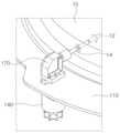
도 2는 도 1의 A부를 나타내는 확대도이다.
도 3은 예시적인 실시예에 따른 상부 전극용 체결 자동화 장치의 체결 모듈을 나타내는 측면도이다.
도 4 내지 도 6은 예시적인 실시예에 따른 상부 전극용 체결 자동화 장치의 체결 모듈의 작동을 설명하기 위한 설명도이다.Figure 1 is a perspective view showing an automated fastening device for an upper electrode according to an exemplary embodiment.
Figure 2 is an enlarged view showing part A of Figure 1.
FIG. 3 is a side view showing a fastening module of an automated fastening device for an upper electrode according to an exemplary embodiment.
FIGS. 4 to 6 are explanatory diagrams for explaining the operation of a fastening module of an automatic fastening device for an upper electrode according to an exemplary embodiment.
이하, 첨부된 도면을 참조하여 본 발명의 바람직한 실시 형태들을 설명한다.Hereinafter, preferred embodiments of the present invention will be described with reference to the attached drawings.
도 1은 예시적인 실시예에 따른 상부 전극용 체결 자동화 장치를 나타내는 사시도이고, 도 2는 도 1의 A부를 나타내는 확대도이고, 도 3은 예시적인 실시예에 따른 상부 전극용 체결 자동화 장치의 체결 모듈을 나타내는 측면도이다.FIG. 1 is a perspective view showing an automated fastening device for an upper electrode according to an exemplary embodiment, FIG. 2 is an enlarged view showing part A of FIG. 1, and FIG. 3 is a side view showing a fastening module of an automated fastening device for an upper electrode according to an exemplary embodiment.
도 1 내지 도 3을 참조하면, 상부 전극용 체결 자동화 장치(100)는 일예로서, 링(110), 복수개의 체결 모듈(120) 및 제어부(190)를 포함하여 구성될 수 있다.Referring to FIGS. 1 to 3, an automatic fastening device (100) for an upper electrode may be configured to include, for example, a ring (110), a plurality of fastening modules (120), and a control unit (190).
링(110)은 후술할 식각 설비(미도시)의 상부 전극(10, 도 4 및 도 5 참조)이 내측에 배치될 수 있도록 중공을 가진 원형의 고리 형상을 가질 수 있다. 일예로서, 상부 전극(10)이 링(110)의 내측에 배치될 수 있도록 링(110)의 내경은 상부 전극(10)보다 크게 형성될 수 있다.The ring (110) may have a hollow, circular ring shape so that an upper electrode (10, see FIGS. 4 and 5) of an etching device (not shown) to be described later may be placed on the inside. As an example, the inner diameter of the ring (110) may be formed to be larger than that of the upper electrode (10) so that the upper electrode (10) may be placed on the inside of the ring (110).
한편, 링(110)의 저면에는 체결 모듈(120)의 반경 방향으로의 이동을 위한 가이드부재(112, 도 2 참조)가 구비될 수 있다. 가이드부재(112)는 복수개의 체결 모듈(120) 각각을 안내하기 위하여 복수개의 체결 모듈(120)의 개수에 대응되는 개수가 구비될 수 있다. 또한, 가이드 부재(112)는 일예로서, LM 가이드일 수 있다. 다만, 이에 한정되지 않으며, 체결 모듈(120)의 반경 방향으로의 이동을 안내할 수 있는 구성이라면 채용 가능할 것이다.Meanwhile, a guide member (112, see FIG. 2) for radial movement of the fastening module (120) may be provided on the bottom surface of the ring (110). The number of guide members (112) may correspond to the number of fastening modules (120) in order to guide each of the plurality of fastening modules (120). In addition, the guide member (112) may be, for example, an LM guide. However, the present invention is not limited thereto, and any configuration capable of guiding the radial movement of the fastening module (120) may be employed.
한편, 링(110)에는 체결 모듈(120)의 반경 방향으로의 이동 시 후술할 체결 모듈(120)의 구동축(150)의 이동을 안내하는 타원 형상을 가지는 관통홀(114)이 구비될 수 있다.Meanwhile, the ring (110) may be provided with a through hole (114) having an elliptical shape that guides the movement of the drive shaft (150) of the fastening module (120), which will be described later, when the fastening module (120) moves in the radial direction.
체결 모듈(120)은 복수개가 링(110)에 설치되며, 링(110)에 반경 방향으로 이동 가능하게 설치된다. 일예로서, 체결 모듈(120)은 8개가 링(110)에 원주 방향으로 따라 동일한 간격으로 상호 이격 배치될 수 있다. 다만, 체결 모듈(120)의 개수는 이에 한정되지 않으며 상부 전극(10)에 설치되는 캠 너트(12)의 개수에 대응되는 개수가 구비될 수 있다.A plurality of fastening modules (120) are installed on the ring (110) and are installed so as to be radially movable on the ring (110). As an example, eight fastening modules (120) may be arranged at equal intervals along the circumference of the ring (110). However, the number of fastening modules (120) is not limited thereto, and a number corresponding to the number of cam nuts (12) installed on the upper electrode (10) may be provided.
여기서, 방향에 대한 용어를 정리하면, 반경 방향은 링(110)의 내주면으로부터 외주면을 향하는 방향 또는 링(110)의 외주면으로부터 링(110)의 내주면을 향하는 방향을 의미하고, 원주 방향은 링(110)의 내주면을 따라 회전되는 방향을 의미한다.Here, to define terms for direction, the radial direction means the direction from the inner surface of the ring (110) toward the outer surface or the direction from the outer surface of the ring (110) toward the inner surface of the ring (110), and the circumferential direction means the direction of rotation along the inner surface of the ring (110).
한편, 체결 모듈(120)은 도 2 및 도 3에 보다 자세하게 도시된 바와 같이, 일예로서, 제1 프레임(130), 구동원(140), 구동축(150), 제2 프레임(160), 동력 전달부(170), 체결용 비트(180)를 포함하여 구성될 수 있다.Meanwhile, the fastening module (120) may be configured to include, for example, a first frame (130), a driving source (140), a driving shaft (150), a second frame (160), a power transmission unit (170), and a fastening bit (180), as illustrated in more detail in FIGS. 2 and 3.
제1 프레임(130)은 링(110)에 반경 방향으로 이동 가능하게 설치된다. 일예로서, 제1 프레임(130)은 도 3에 도시된 가이드부재(112)에 설치되어 반경 방향으로 이동될 수 있다.The first frame (130) is installed so as to be radially movable on the ring (110). As an example, the first frame (130) may be installed on the guide member (112) illustrated in FIG. 3 and may be radially movable.
또한, 제1 프레임(130)에는 구동축(150)이 관통되는 홀(미도시)이 구비될 수 있다. 일예로서, 제1 프레임(130)은 구동원(140)이 설치되는 설치 플레이트(132)와, 설치 플레이트(132)로부터 연장되며 가이드부재(112)에 연결되는 연결부(134)를 구비할 수 있다.In addition, the first frame (130) may be provided with a hole (not shown) through which a driving shaft (150) passes. As an example, the first frame (130) may be provided with an installation plate (132) on which a driving source (140) is installed, and a connecting portion (134) that extends from the installation plate (132) and is connected to a guide member (112).
구동원(140)은 제1 프레임(130)에 고정 설치된다. 일예로서, 구동원(140)은 설치 플레이트(132)의 저면에 고정 설치될 수 있다. 한편, 구동원(140)에는 공압 포트(142)가 구비되며, 공압 포트(142)로부터 공급되는 에어에 의해 구동원(140)이 구동력을 발생시킬 수 있다. 일예로서, 구동원(140)은 로터리 실린더일 수 있다. 다만, 이에 한정되지 않으며 구동원(140)은 공급되는 전원에 의해 회전력을 발생시킬 수 있는 모터 등으로 이루어질 수도 있다.The driving source (140) is fixedly installed to the first frame (130). For example, the driving source (140) may be fixedly installed on the bottom surface of the installation plate (132). Meanwhile, the driving source (140) is provided with a pneumatic port (142), and the driving source (140) may generate driving force by air supplied from the pneumatic port (142). For example, the driving source (140) may be a rotary cylinder. However, the present invention is not limited thereto, and the driving source (140) may be formed of a motor or the like that may generate rotary force by supplied power.
구동축(150)은 구동원(150)에 연결되어 구동력을 전달하는 역할을 수행한다. 한편, 구동축(150)은 제1 프레임(130)을 관통하여 링(110)에 구비되는 관통홀(114)을 관통하도록 배치된다. 또한, 구동축(150)은 동력전달부(160)에 연결되어 동력전달부(160)로 회전력을 전달한다.The driving shaft (150) is connected to the driving source (150) and serves to transmit driving power. Meanwhile, the driving shaft (150) is arranged to penetrate the first frame (130) and the through hole (114) provided in the ring (110). In addition, the driving shaft (150) is connected to the power transmission unit (160) and transmits rotational power to the power transmission unit (160).
일예로서, 구동축(150)은 제1 커플러(102)에 의해 동력전달부(160)에 연결될 수 있다.As an example, the drive shaft (150) can be connected to the power transmission unit (160) by the first coupler (102).
제2 프레임(160)은 링(110)의 상부에 배치되도록 구동축(150)에 연결된다. 또한, 제2 프레임(160)에는 동력전달부(170)가 설치될 수 있다. 이에 따라, 구동축(150)의 회전 시 제2 프레임(160)이 구동축(150)과 같이 회전되면서 동력전달부(170)와 체결용 비트(180)가 회전될 수 있다. 예를 들어, 도 2에 도시된 바와 같이, 체결용 비트(180)가 링(110)의 중심을 향하여 배치된 상태에서 구동원(140)에 의해 구동축(150)이 회전되는 경우 체결용 비트(180)가 링(110)의 상부에 배치되도록 제2 프레임(160)이 회전될 수 있다.The second frame (160) is connected to the drive shaft (150) so as to be placed on the upper portion of the ring (110). In addition, a power transmission unit (170) may be installed on the second frame (160). Accordingly, when the drive shaft (150) rotates, the second frame (160) may rotate together with the drive shaft (150), and the power transmission unit (170) and the fastening bit (180) may rotate. For example, as illustrated in FIG. 2, when the drive shaft (150) is rotated by the drive source (140) while the fastening bit (180) is placed toward the center of the ring (110), the second frame (160) may rotate so that the fastening bit (180) is placed on the upper portion of the ring (110).
한편, 체결용 비트(180)가 상부 전극(10)의 캠 너트(12)에 결합되는 경우 구동원(140)에 의해 구동축(150)이 회전되더라도 제2 프레임(160)은 회전되지 않는다. 즉, 상부 전극(10)의 캠 너트(12)에 결합되는 체결용 비트(180)에 의해 제2 프레임(160)이 구속되어 제2 프레임(160)이 회전되지 않을 수 있다. 하지만, 제2 프레임(160)이 구속이 해제되는 경우 구동원(140)에 의해 제2 프레임(160)이 회전될 수 있는 것이다.Meanwhile, when the fastening bit (180) is coupled to the cam nut (12) of the upper electrode (10), the second frame (160) does not rotate even if the driving shaft (150) is rotated by the driving source (140). That is, the second frame (160) may not rotate because the second frame (160) is restrained by the fastening bit (180) coupled to the cam nut (12) of the upper electrode (10). However, when the restraint of the second frame (160) is released, the second frame (160) may rotate by the driving source (140).
동력전달부(170)는 제2 프레임(160)에 고정 설치된다. 그리고, 동력전달부(170)는 구동축(150)에 연결되며 구동축(150)으로부터 전달되는 회전력의 회전 방향을 변환하는 역할을 수행한다. 일예로서, 동력전달부(170)는 도 3에 도시된 바와 같이, 케이스(172)와 한 쌍의 베벨 기어(174)를 구비할 수 있다. 베벨 기어(174) 중 어느 하나가 구동축(150)에 연결되며 나머지 하나가 체결용 비트(180)에 연결되어 체결용 비트(180)가 회전되는 것이다. 다시 말해, 구동원(140)으롭퉈 발생되는 회전력의 회전 방향이 베벨 기어(174)에 의해 변환될 수 있다.The power transmission unit (170) is fixedly installed on the second frame (160). Then, the power transmission unit (170) is connected to the driving shaft (150) and performs a function of converting the rotational direction of the rotational force transmitted from the driving shaft (150). As an example, the power transmission unit (170) may have a case (172) and a pair of bevel gears (174), as shown in FIG. 3. One of the bevel gears (174) is connected to the driving shaft (150) and the other is connected to the fastening bit (180), so that the fastening bit (180) rotates. In other words, the rotational direction of the rotational force generated by the driving source (140) can be converted by the bevel gear (174).
체결용 비트(180)는 동력전달부(170)에 연결되어 회전된다. 또한, 체결용 비트(180)는 제2 커플러(104)를 통해 동력전달부(170)에 연결될 수 있다. 그리고, 일예로서 체결용 비트(180)는 끝단이 상부 전극(10)의 캠 너트(12) 내주면의 형상에 대응되는 단면을 가지며, 전체적으로 바 형상을 가질 수 있다. 체결용 비트(180)의 끝단은 횡단면이 예를 들어, 팔각형, 육각형 등 다각형 형상을 가질 수 있다. 이와 같이, 체결용 비트(180)가 상부 전극(10)의 캠 너트(12)에 삽입된 상태에서 회전되면 캠 너트(12)가 회전되면서 식각 설비(미도시)에 구비되는 캠 볼트(미도시)를 이동시켜 상부 전극(10)이 식각 설비에 설치되는 것이다.The fastening bit (180) is connected to the power transmission unit (170) and rotates. In addition, the fastening bit (180) may be connected to the power transmission unit (170) through the second coupler (104). In addition, as an example, the fastening bit (180) may have a cross-section whose end corresponds to the shape of the inner surface of the cam nut (12) of the upper electrode (10) and may have an overall bar shape. The end of the fastening bit (180) may have a polygonal shape, such as an octagon or a hexagon, in cross-section. In this way, when the fastening bit (180) is rotated while being inserted into the cam nut (12) of the upper electrode (10), the cam nut (12) rotates and moves the cam bolt (not shown) provided in the etching equipment (not shown), so that the upper electrode (10) is installed in the etching equipment.
제어부(190)는 체결 모듈(120)의 구동원(140)에 연결되어 체결용 비트(180)가 상부 전극(10)의 캠 너트(12)에 삽입되면 복수개의 체결 모듈(120)의 구동원(140)을 일시에 구동시켜 캠 너트(12)를 회전시킨다.The control unit (190) is connected to the driving source (140) of the fastening module (120) so that when the fastening bit (180) is inserted into the cam nut (12) of the upper electrode (10), the driving sources (140) of a plurality of fastening modules (120) are driven simultaneously to rotate the cam nut (12).
이와 같이, 복수개의 체결 모듈(120)을 통해 동시에 상부 전극(10)의 캠 너트(12)를 회전시켜 식각 설비의 상부 전극(10)을 식각 설비에 설치할 수 있다. 이에 따라, 동일한 토크로 캠 너트(12)를 회전시켜 상부 전극을 식각 설비에 설치함으로써 상부 전극(10)이 식각 설비에 고르게 면 접촉할 수 있다. 이에 따라, 고른 면접촉이 이루어지지 않아 발생되었던 온도 산포 결함이 개선될 수 있다.In this way, the upper electrode (10) of the etching equipment can be installed in the etching equipment by simultaneously rotating the cam nut (12) of the upper electrode (10) through a plurality of fastening modules (120). Accordingly, by rotating the cam nut (12) with the same torque to install the upper electrode in the etching equipment, the upper electrode (10) can be evenly brought into surface contact with the etching equipment. Accordingly, the temperature distribution defect that occurred due to the lack of even surface contact can be improved.
즉, 종래에는 작업자에 의해 상부 전극(10)의 캠 너트(12)를 회전시켜 식각 설비의 상부 전극(10)을 식각 설비에 설치하였으며, 이에 따라 서로 다른 토크로 캠 너트(12)를 회전시킴으로써 상부 전극(10)이 식각 설비에 접촉하는 면적이 고르게 분포되지 않는 문제가 있었다. 이에 따라, 온도 산포 결함이 발생되어 유지, 보수 작업을 다시 수행하여야 하는 문제가 있었다.That is, conventionally, the upper electrode (10) of the etching equipment was installed on the etching equipment by rotating the cam nut (12) of the upper electrode (10) by the worker, and accordingly, there was a problem that the area where the upper electrode (10) contacts the etching equipment was not evenly distributed because the cam nut (12) was rotated with different torques. Accordingly, there was a problem that a temperature distribution defect occurred and maintenance work had to be performed again.
하지만, 복수개의 체결 모듈(120)을 구비하는 상부 전극용 체결 자동화 장치(100)를 통해 상부 전극(10)을 식각 설비에 설치함으로써 상부 전극(10)이 식각 설비에 접촉하는 면적이 고르게 분포될 수 있다. 이에 따라, 온도 산포 결함이 발생되는 것을 방지할 수 있다.However, by installing the upper electrode (10) in the etching equipment through the upper electrode fastening automation device (100) having a plurality of fastening modules (120), the area where the upper electrode (10) comes into contact with the etching equipment can be evenly distributed. Accordingly, the occurrence of a temperature distribution defect can be prevented.
또한, 상부 전극용 체결 자동화 장치(100)를 통해 상부 전극(10)을 식각 설비에 설치함으로써 상부 전극(10)의 설치 시간을 단축할 수 있다.In addition, the installation time of the upper electrode (10) can be shortened by installing the upper electrode (10) in the etching equipment through the upper electrode fastening automation device (100).
이하에서는 도면을 참조하여 본 발명의 예시적인 실시예에 따른 상부 전극용 체결 자동화 장치(100)의 작동을 설명하기로 한다.Hereinafter, the operation of an automatic fastening device (100) for an upper electrode according to an exemplary embodiment of the present invention will be described with reference to the drawings.
먼저, 도 4에 도시된 바와 같이, 상부 전극(10)이 링(110)의 중앙에 배치되도록 상부 전극용 체결 자동화 장치(100)가 배치된다. 이때, 상부 전극(10)의 캠 너트(12)가 설치되는 설치홀(14)로부터 소정 간격 이격되도록 체결용 비트(180)가 배치된다.First, as shown in Fig. 4, the upper electrode fastening automation device (100) is placed so that the upper electrode (10) is placed in the center of the ring (110). At this time, the fastening bit (180) is placed so as to be spaced apart from the installation hole (14) in which the cam nut (12) of the upper electrode (10) is installed by a predetermined distance.
이후, 도 5에 도시된 바와 같이, 복수개의 체결 모듈(120)이 동시에 링(110)의 반경 방향으로 이동된다. 다시 말해, 복수개의 체결 모듈(120)의 제1 프레임(130)이 링(110)의 가이드부재(112, 도 3 참조)를 따라 이동되어 체결용 비트(180)가 전진한다. 이에 따라, 체결용 비트(180)가 설치홀(14)로 삽입되어 캠 너트(12)에 결합된다.Thereafter, as shown in FIG. 5, a plurality of fastening modules (120) are simultaneously moved in the radial direction of the ring (110). In other words, the first frame (130) of the plurality of fastening modules (120) is moved along the guide member (112, see FIG. 3) of the ring (110), and the fastening bit (180) advances. Accordingly, the fastening bit (180) is inserted into the installation hole (14) and coupled to the cam nut (12).
이후, 도 6에 도시된 바와 같이, 구동원(140)에 의해 체결용 비트(180)가 회전되면서 상부 전극(10)이 식각 설비에 결합된다. 다시 말해, 복수개의 체결 모듈(120) 각각에 구비되는 구동원(140)이 작동되어 복수개의 체결 모듈(120) 각각에 구비되는 체결용 비트(180)가 회전된다. 이에 따라, 상부 전극(10)의 캠 너트(12)가 회전되어 식각 설비의 캠 볼트(미도시)에 고정되면서 상부 전극(10)이 식각 설비에 설치된다. 이와 같이, 복수개의 체결 모듈(120)이 동시에 작동하여 캠 너트(12)를 회전시켜 상부 전극(10)을 식각 설비에 결합함으로써 상부 전극(10)이 식각 설비에 고르게 면 접촉할 수 있다. 따라서, 고른 면접촉이 이루어지지 않아 발생되었던 온도 산포 결함이 개선될 수 있다.Thereafter, as illustrated in FIG. 6, the upper electrode (10) is coupled to the etching equipment as the fastening bit (180) is rotated by the driving source (140). In other words, the driving source (140) provided in each of the plurality of fastening modules (120) is operated so that the fastening bit (180) provided in each of the plurality of fastening modules (120) is rotated. Accordingly, the cam nut (12) of the upper electrode (10) is rotated and fixed to the cam bolt (not shown) of the etching equipment so that the upper electrode (10) is installed in the etching equipment. In this way, the plurality of fastening modules (120) are operated simultaneously to rotate the cam nut (12) so that the upper electrode (10) is coupled to the etching equipment so that the upper electrode (10) can evenly contact the etching equipment. Therefore, the temperature distribution defect that occurred due to the lack of even surface contact can be improved.
다시 말해, 복수개의 체결 모듈(120)을 통해 동시에 상부 전극(10)의 캠 너트(12)를 회전시켜 식각 설비의 상부 전극(10)을 식각 설비에 설치할 수 있다. 이에 따라, 동일한 토크로 캠 너트(12)를 회전시켜 상부 전극을 식각 설비에 설치함으로써 상부 전극(10)이 식각 설비에 고르게 면 접촉할 수 있다. 이에 따라, 고른 면접촉이 이루어지지 않아 발생되었던 온도 산포 결함이 개선될 수 있다.In other words, the upper electrode (10) of the etching equipment can be installed in the etching equipment by simultaneously rotating the cam nut (12) of the upper electrode (10) through a plurality of fastening modules (120). Accordingly, by rotating the cam nut (12) with the same torque to install the upper electrode in the etching equipment, the upper electrode (10) can be brought into even surface contact with the etching equipment. Accordingly, the temperature distribution defect that occurred due to the lack of even surface contact can be improved.
즉, 종래에는 작업자에 의해 상부 전극(10)의 캠 너트(12)를 회전시켜 식각 설비의 상부 전극(10)을 식각 설비에 설치하였으며, 이에 따라 서로 다른 토크로 캠 너트(12)를 회전시킴으로써 상부 전극(10)이 식각 설비에 접촉하는 면적이 고르게 분포되지 않는 문제가 있었다. 이에 따라, 온도 산포 결함이 발생되어 유지, 보수 작업을 다시 수행하여야 하는 문제가 있었다.That is, conventionally, the upper electrode (10) of the etching equipment was installed on the etching equipment by rotating the cam nut (12) of the upper electrode (10) by the worker, and accordingly, there was a problem that the area where the upper electrode (10) contacts the etching equipment was not evenly distributed because the cam nut (12) was rotated with different torques. Accordingly, there was a problem that a temperature distribution defect occurred and maintenance work had to be performed again.
하지만, 복수개의 체결 모듈(120)을 구비하는 상부 전극용 체결 자동화 장치(100)를 통해 상부 전극(10)을 식각 설비에 설치함으로써 상부 전극(10)이 식각 설비에 접촉하는 면적이 고르게 분포될 수 있다. 이에 따라, 온도 산포 결함이 발생되는 것을 방지할 수 있다.However, by installing the upper electrode (10) in the etching equipment through the upper electrode fastening automation device (100) having a plurality of fastening modules (120), the area where the upper electrode (10) comes into contact with the etching equipment can be evenly distributed. Accordingly, the occurrence of a temperature distribution defect can be prevented.
또한, 상부 전극용 체결 자동화 장치(100)를 통해 상부 전극(10)을 식각 설비에 설치함으로써 상부 전극(10)의 설치 시간을 단축할 수 있다.In addition, the installation time of the upper electrode (10) can be shortened by installing the upper electrode (10) in the etching equipment through the upper electrode fastening automation device (100).
이상에서 본 발명의 실시예에 대하여 상세하게 설명하였지만 본 발명의 권리범위는 이에 한정되는 것은 아니고, 청구범위에 기재된 본 발명의 기술적 사상을 벗어나지 않는 범위 내에서 다양한 수정 및 변형이 가능하다는 것은 당 기술분야의 통상의 지식을 가진 자에게는 자명할 것이다.Although the embodiments of the present invention have been described in detail above, the scope of the present invention is not limited thereto, and it will be apparent to those skilled in the art that various modifications and variations are possible within a scope that does not depart from the technical spirit of the present invention described in the claims.
100 : 상부 전극용 체결 자동화 장치
110 : 링
120 : 체결 모듈
130 : 제1 프레임
140 : 구동원
150 : 구동축
160 : 제2 프레임
170 : 동력전달부
180 : 체결용 비트
190 : 제어부100: Automatic fastening device for upper electrode
110 : Ring
120 : Conclusion module
130 : 1st frame
140 : Drive source
150 : Drive shaft
160 : 2nd frame
170 : Power transmission unit
180 : Bit for fastening
190 : Control Unit
Claims (10)
Translated fromKorean상기 링에 반경 방향으로 이동 가능하게 설치되는 복수개의 체결 모듈;
을 포함하며,
상기 체결 모듈은
상기 링에 반경 방향으로 이동 가능하게 설치되는 제1 프레임;
상기 제1 프레임의 하부에 설치되는 구동원;
상기 구동원으로부터 구동력을 전달하는 구동축;
상기 구동축에 연결되며 회전 방향을 변환하는 동력전달부; 및
상기 동력 전달부에 연결되어 회전되는 체결용 비트;
를 포함하며,
상기 복수개의 체결 모듈은 동시에 작동하여 식각 설비의 상부 전극을 상기 식각 설비에 설치하며,
상기 링에는 상기 구동축이 관통하여 배치되며 상기 구동축이 이동 가능하도록 타원 형상을 가지는 관통홀이 구비되는 상부 전극용 체결 자동화 장치.
A ring having a hollow circular ring shape; and
A plurality of fastening modules radially movably installed on the above ring;
Including,
The above-mentioned fastening module
A first frame radially movably installed on the above ring;
A driving source installed at the lower part of the first frame;
A driving shaft that transmits driving power from the above driving source;
A power transmission unit connected to the above driving shaft and converting the direction of rotation; and
A fastening bit that is connected to the above power transmission unit and rotates;
Including,
The above multiple fastening modules operate simultaneously to install the upper electrode of the etching equipment into the etching equipment,
An automatic fastening device for an upper electrode, wherein the ring has a through hole having an oval shape through which the driving shaft is positioned and through which the driving shaft can move.
상기 링에는 상기 체결 모듈의 이동을 가이드하기 위한 가이드 부재가 설치되는 상부 전극용 체결 자동화 장치.
In the first paragraph,
An upper electrode fastening automation device, wherein a guide member for guiding the movement of the fastening module is installed on the ring.
상기 가이드 부재는 LM 가이드로 이루어지는 상부 전극용 체결 자동화 장치.
In the second paragraph,
The above guide member is an automated fastening device for an upper electrode made of an LM guide.
상기 링의 상부에 배치되며 상기 동력전달부가 설치되는 제2 프레임을 더 포함하는 상부 전극용 체결 자동화 장치.
In the first paragraph,
An automated fastening device for an upper electrode, further comprising a second frame disposed on the upper portion of the above ring and on which the power transmission unit is installed.
상기 구동원은 공압 포트를 구비하는 로터리 실린더로 이루어지는 상부 전극용 체결 자동화 장치.
In the first paragraph,
The above driving source is an automated device for fastening an upper electrode, which comprises a rotary cylinder having a pneumatic port.
상기 동력 전달부는 회전 방향을 전환하기 위한 복수개의 베벨 기어를 구비하는 상부 전극용 체결 자동화 장치.
In the first paragraph,
The above power transmission unit is an automatic fastening device for an upper electrode having a plurality of bevel gears for changing the direction of rotation.
상기 체결용 비트의 적어도 끝단은 상기 상부 전극에 설치되는 캠 너트의 형상에 대응되는 단면 형상을 가지는 상부 전극용 체결 자동화 장치.
In the first paragraph,
An automatic fastening device for an upper electrode, wherein at least one end of the fastening bit has a cross-sectional shape corresponding to the shape of a cam nut installed on the upper electrode.
상기 구동원에 연결되어 상기 구동원의 동작을 제어하는 제어부를 더 포함하는 상부 전극용 체결 자동화 장치.
In the first paragraph,
An automated fastening device for an upper electrode, further comprising a control unit connected to the driving source and controlling the operation of the driving source.
상기 링에 반경 방향으로 이동 가능하게 설치되는 제1 프레임과, 상기 제1 프레임에 설치되는 구동원 및 상기 구동원에 연결되어 회전되는 체결용 비트는 구비하는 복수개의 체결 모듈;
을 포함하며,
상기 복수개의 체결 모듈 각각은 식각 설비의 상부 전극을 상기 식각 설비에 설치하는 경우 상기 제1 프레임이 이동되어 상기 체결용 비트가 상기 상부 전극의 캠 너트에 삽입되어 회전되면서 일시에 상기 상부 전극을 상기 식각 설비에 설치하는 상부 전극용 체결 자동화 장치.
a ring having a ring shape; and
A plurality of fastening modules having a first frame radially movable on the ring, a driving source installed on the first frame, and a fastening bit connected to the driving source and rotatable;
Including,
An automatic upper electrode fastening device in which, when each of the plurality of fastening modules installs an upper electrode of an etching facility into the etching facility, the first frame is moved so that the fastening bit is inserted into the cam nut of the upper electrode and rotates to simultaneously install the upper electrode into the etching facility.
Priority Applications (2)
| Application Number | Priority Date | Filing Date | Title |
|---|---|---|---|
| KR1020200110519AKR102780359B1 (en) | 2020-08-31 | 2020-08-31 | Fastening automation apparatus for upper electrode |
| US17/213,017US12119210B2 (en) | 2020-08-31 | 2021-03-25 | Fastening automation apparatus for upper electrode |
Applications Claiming Priority (1)
| Application Number | Priority Date | Filing Date | Title |
|---|---|---|---|
| KR1020200110519AKR102780359B1 (en) | 2020-08-31 | 2020-08-31 | Fastening automation apparatus for upper electrode |
Publications (2)
| Publication Number | Publication Date |
|---|---|
| KR20220030431A KR20220030431A (en) | 2022-03-11 |
| KR102780359B1true KR102780359B1 (en) | 2025-03-13 |
Family
ID=80356982
Family Applications (1)
| Application Number | Title | Priority Date | Filing Date |
|---|---|---|---|
| KR1020200110519AActiveKR102780359B1 (en) | 2020-08-31 | 2020-08-31 | Fastening automation apparatus for upper electrode |
Country Status (2)
| Country | Link |
|---|---|
| US (1) | US12119210B2 (en) |
| KR (1) | KR102780359B1 (en) |
Families Citing this family (2)
| Publication number | Priority date | Publication date | Assignee | Title |
|---|---|---|---|---|
| KR102780359B1 (en)* | 2020-08-31 | 2025-03-13 | 삼성전자주식회사 | Fastening automation apparatus for upper electrode |
| USD973461S1 (en)* | 2020-10-23 | 2022-12-27 | Hong Ann Tool Industries Co., Ltd. | Anti-slip fastener driver |
Family Cites Families (11)
| Publication number | Priority date | Publication date | Assignee | Title |
|---|---|---|---|---|
| JP3313224B2 (en)* | 1994-01-25 | 2002-08-12 | 松下電器産業株式会社 | Electronic component mounting equipment |
| SE9503243D0 (en) | 1995-09-19 | 1995-09-19 | Atlas Copco Tools Ab | Method for simultaneous tightening of two or more screw joints |
| KR100638916B1 (en) | 2000-05-17 | 2006-10-25 | 동경 엘렉트론 주식회사 | Processing unit and its maintenance method |
| US6753498B2 (en) | 2000-07-20 | 2004-06-22 | Tokyo Electron Limited | Automated electrode replacement apparatus for a plasma processing system |
| KR101346081B1 (en) | 2006-06-20 | 2013-12-31 | 참엔지니어링(주) | Plasma etching chamber |
| US8221582B2 (en) | 2008-07-07 | 2012-07-17 | Lam Research Corporation | Clamped monolithic showerhead electrode |
| JP3160877U (en) | 2009-10-13 | 2010-07-15 | ラム リサーチ コーポレーションLam Research Corporation | End-clamping and machine-fixed inner electrode of showerhead electrode assembly |
| DE102015013495B4 (en)* | 2015-10-16 | 2018-04-26 | Mühlbauer Gmbh & Co. Kg | Receiving device for components and methods for removing defective components from this |
| US10207538B2 (en) | 2016-01-19 | 2019-02-19 | Jacob Black | Device for simultaneously removing and tightening a plurality of lug nuts |
| CN111566798B (en)* | 2018-01-19 | 2023-10-27 | 株式会社塞米克斯 | Wafer detector |
| KR102780359B1 (en)* | 2020-08-31 | 2025-03-13 | 삼성전자주식회사 | Fastening automation apparatus for upper electrode |
- 2020
- 2020-08-31KRKR1020200110519Apatent/KR102780359B1/enactiveActive
- 2021
- 2021-03-25USUS17/213,017patent/US12119210B2/enactiveActive
Also Published As
| Publication number | Publication date |
|---|---|
| US12119210B2 (en) | 2024-10-15 |
| KR20220030431A (en) | 2022-03-11 |
| US20220068609A1 (en) | 2022-03-03 |
Similar Documents
| Publication | Publication Date | Title |
|---|---|---|
| KR102780359B1 (en) | Fastening automation apparatus for upper electrode | |
| EP2633943B1 (en) | Single-shaft yaw electric bolt-tightening machine | |
| CN104995003B (en) | Industrial robot | |
| EP0968788A2 (en) | Method and apparatus for controlling downforce during friction stir welding | |
| CN116457151A (en) | Couplings for Electric Torque Wrench Gearbox Replacement | |
| CN211361519U (en) | Cam type automatic rotating and lifting tool changing mechanism | |
| JP7299588B2 (en) | Centering mechanism for shaft processing machine | |
| EP4026618A1 (en) | Automatic device or tool for removing and installing means for fastening liners in a mill; method for installing the means for fastening a liner; and method for removing the means for fastening a liner | |
| KR101590798B1 (en) | Over-ray welding apparatus | |
| KR102556199B1 (en) | assembling method of pin gear roller screw | |
| KR101727740B1 (en) | Multistage auto loader | |
| KR20180056435A (en) | Rotating type jig device | |
| GB2236824A (en) | Tightening and loosening apparatus for flange bolts and nuts | |
| JP3567754B2 (en) | Work holding device and bolt press-in equipment using this work holding device | |
| CN211465395U (en) | Mounting and positioning mechanism of end cover | |
| JP2023130556A (en) | Wafer rotation holding device | |
| CN215733853U (en) | Motor mounting structure of processing equipment | |
| KR100586718B1 (en) | Power train of material winding twin drum | |
| CN220839026U (en) | Flange processing tool | |
| JPH0115482Y2 (en) | ||
| EP4019175A1 (en) | Machine tool with an automatic system for replacing tools and related method | |
| US20230311214A1 (en) | Externally mounted flange facing system | |
| CN219902224U (en) | Chassis of industrial robot | |
| WO2021044477A1 (en) | Robot origin point setting device and method | |
| CN222473441U (en) | Transmission device and tire forming equipment with same |
Legal Events
| Date | Code | Title | Description |
|---|---|---|---|
| PA0109 | Patent application | St.27 status event code:A-0-1-A10-A12-nap-PA0109 | |
| PG1501 | Laying open of application | St.27 status event code:A-1-1-Q10-Q12-nap-PG1501 | |
| A201 | Request for examination | ||
| PA0201 | Request for examination | St.27 status event code:A-1-2-D10-D11-exm-PA0201 | |
| E902 | Notification of reason for refusal | ||
| PE0902 | Notice of grounds for rejection | St.27 status event code:A-1-2-D10-D21-exm-PE0902 | |
| E13-X000 | Pre-grant limitation requested | St.27 status event code:A-2-3-E10-E13-lim-X000 | |
| P11-X000 | Amendment of application requested | St.27 status event code:A-2-2-P10-P11-nap-X000 | |
| P13-X000 | Application amended | St.27 status event code:A-2-2-P10-P13-nap-X000 | |
| E701 | Decision to grant or registration of patent right | ||
| PE0701 | Decision of registration | St.27 status event code:A-1-2-D10-D22-exm-PE0701 | |
| PR0701 | Registration of establishment | St.27 status event code:A-2-4-F10-F11-exm-PR0701 | |
| PR1002 | Payment of registration fee | St.27 status event code:A-2-2-U10-U11-oth-PR1002 Fee payment year number:1 | |
| PG1601 | Publication of registration | St.27 status event code:A-4-4-Q10-Q13-nap-PG1601 |